JP6890829B2 - Parallel 2-axis hinges and electronic devices - Google Patents

Parallel 2-axis hinges and electronic devices Download PDF

Info

Publication number
JP6890829B2
JP6890829B2 JP2017157703A JP2017157703A JP6890829B2 JP 6890829 B2 JP6890829 B2 JP 6890829B2 JP 2017157703 A JP2017157703 A JP 2017157703A JP 2017157703 A JP2017157703 A JP 2017157703A JP 6890829 B2 JP6890829 B2 JP 6890829B2
Authority
JP
Japan
Prior art keywords
hinge
hinge shaft
cam
housing
shaft
Prior art date
Legal status (The legal status is an assumption and is not a legal conclusion. Google has not performed a legal analysis and makes no representation as to the accuracy of the status listed.)
Active
Application number
JP2017157703A
Other languages
Japanese (ja)
Other versions
JP2019035474A (en
JP2019035474A5 (en
Inventor
華偉 林
華偉 林
Current Assignee (The listed assignees may be inaccurate. Google has not performed a legal analysis and makes no representation or warranty as to the accuracy of the list.)
Naturaleza One Co Ltd
Original Assignee
Naturaleza One Co Ltd
Priority date (The priority date is an assumption and is not a legal conclusion. Google has not performed a legal analysis and makes no representation as to the accuracy of the date listed.)
Filing date
Publication date
Application filed by Naturaleza One Co Ltd filed Critical Naturaleza One Co Ltd
Priority to JP2017157703A priority Critical patent/JP6890829B2/en
Priority to US16/044,162 priority patent/US10845849B2/en
Priority to TW107128676A priority patent/TWI682262B/en
Priority to CN201810937660.0A priority patent/CN109404412B/en
Publication of JP2019035474A publication Critical patent/JP2019035474A/en
Publication of JP2019035474A5 publication Critical patent/JP2019035474A5/ja
Application granted granted Critical
Publication of JP6890829B2 publication Critical patent/JP6890829B2/en
Active legal-status Critical Current
Anticipated expiration legal-status Critical

Links

Images

Classifications

    • GPHYSICS
    • G06COMPUTING; CALCULATING OR COUNTING
    • G06FELECTRIC DIGITAL DATA PROCESSING
    • G06F1/00Details not covered by groups G06F3/00 - G06F13/00 and G06F21/00
    • G06F1/16Constructional details or arrangements
    • G06F1/1613Constructional details or arrangements for portable computers
    • G06F1/1633Constructional details or arrangements of portable computers not specific to the type of enclosures covered by groups G06F1/1615 - G06F1/1626
    • G06F1/1675Miscellaneous details related to the relative movement between the different enclosures or enclosure parts
    • G06F1/1681Details related solely to hinges
    • FMECHANICAL ENGINEERING; LIGHTING; HEATING; WEAPONS; BLASTING
    • F16ENGINEERING ELEMENTS AND UNITS; GENERAL MEASURES FOR PRODUCING AND MAINTAINING EFFECTIVE FUNCTIONING OF MACHINES OR INSTALLATIONS; THERMAL INSULATION IN GENERAL
    • F16CSHAFTS; FLEXIBLE SHAFTS; ELEMENTS OR CRANKSHAFT MECHANISMS; ROTARY BODIES OTHER THAN GEARING ELEMENTS; BEARINGS
    • F16C11/00Pivots; Pivotal connections
    • F16C11/04Pivotal connections
    • EFIXED CONSTRUCTIONS
    • E05LOCKS; KEYS; WINDOW OR DOOR FITTINGS; SAFES
    • E05DHINGES OR SUSPENSION DEVICES FOR DOORS, WINDOWS OR WINGS
    • E05D3/00Hinges with pins
    • E05D3/06Hinges with pins with two or more pins
    • E05D3/12Hinges with pins with two or more pins with two parallel pins and one arm
    • EFIXED CONSTRUCTIONS
    • E05LOCKS; KEYS; WINDOW OR DOOR FITTINGS; SAFES
    • E05DHINGES OR SUSPENSION DEVICES FOR DOORS, WINDOWS OR WINGS
    • E05D11/00Additional features or accessories of hinges
    • E05D11/08Friction devices between relatively-movable hinge parts
    • E05D11/087Friction devices between relatively-movable hinge parts with substantially axial friction, e.g. friction disks
    • EFIXED CONSTRUCTIONS
    • E05LOCKS; KEYS; WINDOW OR DOOR FITTINGS; SAFES
    • E05DHINGES OR SUSPENSION DEVICES FOR DOORS, WINDOWS OR WINGS
    • E05D7/00Hinges or pivots of special construction
    • GPHYSICS
    • G06COMPUTING; CALCULATING OR COUNTING
    • G06FELECTRIC DIGITAL DATA PROCESSING
    • G06F1/00Details not covered by groups G06F3/00 - G06F13/00 and G06F21/00
    • G06F1/16Constructional details or arrangements
    • G06F1/1613Constructional details or arrangements for portable computers
    • G06F1/1615Constructional details or arrangements for portable computers with several enclosures having relative motions, each enclosure supporting at least one I/O or computing function
    • G06F1/1616Constructional details or arrangements for portable computers with several enclosures having relative motions, each enclosure supporting at least one I/O or computing function with folding flat displays, e.g. laptop computers or notebooks having a clamshell configuration, with body parts pivoting to an open position around an axis parallel to the plane they define in closed position
    • G06F1/1618Constructional details or arrangements for portable computers with several enclosures having relative motions, each enclosure supporting at least one I/O or computing function with folding flat displays, e.g. laptop computers or notebooks having a clamshell configuration, with body parts pivoting to an open position around an axis parallel to the plane they define in closed position the display being foldable up to the back of the other housing with a single degree of freedom, e.g. by 360° rotation over the axis defined by the rear edge of the base enclosure
    • EFIXED CONSTRUCTIONS
    • E05LOCKS; KEYS; WINDOW OR DOOR FITTINGS; SAFES
    • E05YINDEXING SCHEME RELATING TO HINGES OR OTHER SUSPENSION DEVICES FOR DOORS, WINDOWS OR WINGS AND DEVICES FOR MOVING WINGS INTO OPEN OR CLOSED POSITION, CHECKS FOR WINGS AND WING FITTINGS NOT OTHERWISE PROVIDED FOR, CONCERNED WITH THE FUNCTIONING OF THE WING
    • E05Y2900/00Application of doors, windows, wings or fittings thereof
    • E05Y2900/60Application of doors, windows, wings or fittings thereof for other use
    • E05Y2900/606Application of doors, windows, wings or fittings thereof for other use for electronic devices

Description

本発明は、例えば電子機器、例えばノートパソコンにおいてキーボード側の第1筐体とディスプレイ側の第2筐体を開閉可能に連結する平行2軸ヒンジに関し、第1筐体と第2筐体の相対的開閉操作時に他の機構を動作させることができるように成した平行2軸ヒンジ、及びこの平行2軸ヒンジを用いた電子機器に関する。 The present invention relates to a parallel biaxial hinge that connects a first housing on the keyboard side and a second housing on the display side in an electronic device, for example, a notebook computer so as to be openable and closable. The present invention relates to a parallel biaxial hinge formed so that another mechanism can be operated during a target opening / closing operation, and an electronic device using the parallel biaxial hinge.

キーボードを備えた第1筐体とタッチ操作機能を持った液晶ディスプレイを備えた第2筐体とを平行2軸ヒンジにより連結し、第1筐体に対して第2筐体を0度〜360度の範囲で回動させることが可能な電子機器の一種としてのノートパソコンが実用化されている。 The first housing equipped with a keyboard and the second housing equipped with a liquid crystal display having a touch operation function are connected by a parallel biaxial hinge, and the second housing is connected to the first housing at 0 degrees to 360 degrees. A notebook computer as a kind of electronic device that can be rotated within a range of degrees has been put into practical use.

このようなノートパソコンでは、第1筐体と第2筐体を開いて使用する際に、キーボード自体が上昇して操作しやすいように成し、第1筐体と第2筐体を相対的に180度ずつ合計で360度開いて第1筐体のキーボード側を下側にして第2筐体のディスプレイ画面をタッチ操作する場合には、キーボードが沈み込んで誤動作の生じないようにする必要がある。 In such a notebook computer, when the first housing and the second housing are opened and used, the keyboard itself is raised so as to be easy to operate, and the first housing and the second housing are relative to each other. When touching the display screen of the second housing with the keyboard side of the first housing facing down, it is necessary to prevent the keyboard from sinking and causing malfunctions. There is.

特許文献1には、開閉蓋部の0度−360度の開成角度に応じて、本体部に対してキーボードを上昇/下降させる機構が示される。ここでは、平行2軸ヒンジの第1ヒンジシャフトと、第2ヒンジシャフトと、がヒンジ部によって回動可能に支持され、対称に回動されている。そして、第1ヒンジシャフトに挿通させてヒンジ部と一体に回動するカムを設け、第1ヒンジシャフトに固定されたベース部材に、スライド移動可能なカムフォロアを設けている。これにより、ベース部材上のカムフォロアに、第1ヒンジシャフトと第2ヒンジシャフトとの回動に伴うベース部材に沿った方向の直線移動を取り出している。 Patent Document 1 discloses a mechanism for raising / lowering the keyboard with respect to the main body portion according to an opening angle of 0 ° -360 ° of the opening / closing lid portion. Here, the first hinge shaft and the second hinge shaft of the parallel biaxial hinge are rotatably supported by the hinge portion and are rotated symmetrically. Then, a cam that is inserted through the first hinge shaft and rotates integrally with the hinge portion is provided, and a slide-movable cam follower is provided on the base member fixed to the first hinge shaft. As a result, the cam follower on the base member takes out a linear movement in the direction along the base member due to the rotation of the first hinge shaft and the second hinge shaft.

特開2016−80031号公報Japanese Unexamined Patent Publication No. 2016-80031

特許文献1の平行2軸ヒンジは、第1ヒンジシャフトと第2ヒンジシャフトとの回動に伴って直線移動を取り出す機構に必要な部品点数が多いため小型化が難しい。カムを小型化するとカムフォロアから取り出せる直線移動の振幅が小さくなり、部品強度が低下して取出される直線移動の力も小さくなる。本発明は、小型化が可能で第1ヒンジシャフトと第2ヒンジシャフトとの回動に伴って比較的に大きな振幅と大きな力の直線移動を取り出すことができる平行2軸ヒンジを提供することを目的としている。 The parallel biaxial hinge of Patent Document 1 is difficult to miniaturize because the number of parts required for the mechanism for taking out the linear movement with the rotation of the first hinge shaft and the second hinge shaft is large. When the cam is miniaturized, the amplitude of the linear movement that can be taken out from the cam follower becomes smaller, the strength of the parts decreases, and the force of the linear movement that is taken out becomes smaller. The present invention provides a parallel biaxial hinge that can be miniaturized and can take out a linear movement of a relatively large amplitude and a large force with the rotation of the first hinge shaft and the second hinge shaft. I am aiming.

本発明の平行2軸ヒンジは、第1筐体側に取り付けられる第1ヒンジシャフトと、第2筐体側に取り付けられる第2ヒンジシャフトとを、同期回転手段を介して相対的に回動させるヒンジ部と、このヒンジ部の回動動作に伴って所定の操作出力が取出される受動操作部と、からなり、この受動操作部を、前記第1ヒンジシャフトと一体に回動するように設けられたベース部材と、前記ヒンジ部に設けられ、前記ヒンジ部の回動動作に伴って前記第1ヒンジシャフトに対して回動する係合部材と、前記係合部材に係合する被係合部を外周面に有し、前記第1ヒンジシャフトに外挿して設けられ、前記ベース部材に対して前記第1ヒンジシャフトの回転軸線方向に移動可能な外挿移動部材と、で構成したものである。そして、前記外挿移動部材は、前記ヒンジ部の回動動作に伴って前記被係合部を前記係合部材に案内されて前記回転軸線方向に移動するように成されている。 The parallel biaxial hinge of the present invention is a hinge portion in which a first hinge shaft attached to the first housing side and a second hinge shaft attached to the second housing side are relatively rotated via a synchronous rotation means. It is composed of a passive operation unit from which a predetermined operation output is taken out in association with the rotation operation of the hinge portion, and the passive operation unit is provided so as to rotate integrally with the first hinge shaft. A base member, an engaging member provided on the hinge portion and rotating with respect to the first hinge shaft as the hinge portion rotates, and an engaged portion engaging with the engaging member. It is composed of an external moving member which is provided on the outer peripheral surface and is externally provided to the first hinge shaft and is movable with respect to the base member in the direction of the rotation axis of the first hinge shaft. The extrapolated moving member is formed so that the engaged portion is guided by the engaging member and moves in the direction of the rotation axis along with the rotational operation of the hinge portion.

本発明によれば、小型化が可能で第1ヒンジシャフトと第2ヒンジシャフトとの回動に伴って比較的に大きな振幅と大きな力の直線移動を取り出すことができる平行2軸ヒンジを提供することができる。 According to the present invention, there is provided a parallel biaxial hinge that can be miniaturized and can take out a linear movement of a relatively large amplitude and a large force with the rotation of the first hinge shaft and the second hinge shaft. be able to.

実施例1のノートパソコンの説明図である。図1中、(a)は第1筐体に対して第2筐体を開いた状態、(b)は第1筐体に対して第2筐体を閉じた状態である。It is explanatory drawing of the notebook computer of Example 1. In FIG. 1, (a) is a state in which the second housing is open with respect to the first housing, and (b) is a state in which the second housing is closed with respect to the first housing. 第1筐体に対する第2筐体の開成角度位置の説明図である。図2中、(a)は、0度、(b)は80度、(c)は254度、(d)は270度、(e)は360度である。It is explanatory drawing of the opening angle position of the 2nd housing with respect to the 1st housing. In FIG. 2, (a) is 0 degrees, (b) is 80 degrees, (c) is 254 degrees, (d) is 270 degrees, and (e) is 360 degrees. 実施例1の平行2軸ヒンジの斜視図である。It is a perspective view of the parallel biaxial hinge of Example 1. FIG. 実施例1の平行2軸ヒンジの分解斜視図である。It is an exploded perspective view of the parallel biaxial hinge of Example 1. FIG. 第1ヒンジシャフトの説明図である。(a)は平面図、(b)は正面図、(c)は側面図である。It is explanatory drawing of the 1st hinge shaft. (A) is a plan view, (b) is a front view , and (c) is a side view . 第2ヒンジシャフトの説明図である。(a)は平面図、(b)は正面図、(c)は側面図である。It is explanatory drawing of the 2nd hinge shaft. (A) is a plan view, (b) is a front view , and (c) is a side view . 回転制御部の組立状態の説明図である。It is explanatory drawing of the assembly state of the rotation control part. 同期回転部の構成の説明図である。(a)は同期回転部、(b)はギアサポート部材の左側面図、(c)はギアサポート部材の右側面図である。It is explanatory drawing of the structure of the synchronous rotation part. (A) is a synchronous rotating part, (b) is a left side view of the gear support member, and (c) is a right side view of the gear support member. フリクションプレートの構造の説明図である。(a)は同期回転部側の面、(b)は第1付勢部側の面である。It is explanatory drawing of the structure of a friction plate. (A) is a surface on the synchronous rotating portion side, and (b) is a surface on the first urging portion side. カムプレート部材の構造の説明図である。(a)は斜視図、(b)は第1付勢部側の面、(c)は同期回転部側の面である。It is explanatory drawing of the structure of a cam plate member. (A) is a perspective view, (b) is a surface on the first urging portion side, and (c) is a surface on the synchronous rotating portion side. 第1フリクションワッシャ及び第2フリクションワッシャの構造の説明図である。(a)は第1付勢部側の面、(b)は同期回転部側の面である。It is explanatory drawing of the structure of the 1st friction washer and the 2nd friction washer. (A) is a surface on the first urging portion side, and (b) is a surface on the synchronous rotating portion side. 第1カムフォロワ及び第2カムフォロアの構造の説明図である。It is explanatory drawing of the structure of the 1st cam follower and the 2nd cam follower. ヒンジケースの構造を示すもので、(a)その側面図、(b)はその縦断面図である。The structure of the hinge case is shown, and (a) a side view thereof and (b) a vertical sectional view thereof. 作動機構の構成の説明図である。It is explanatory drawing of the structure of the operation mechanism. 軸方向駆動部の構成の説明図である。It is explanatory drawing of the structure of the axial drive part. 増幅機構の動作の説明図である。(a)は0度、(b)は80度、(c)は254度である。It is explanatory drawing of the operation of the amplification mechanism. (A) is 0 degrees, (b) is 80 degrees, and (c) is 254 degrees. 増幅機構の動作の説明図である。(a)は270度、(b)は360度である。It is explanatory drawing of the operation of the amplification mechanism. (A) is 270 degrees and (b) is 360 degrees.

本発明の実施の形態を添付した図面に基づいて詳細に説明する。 Embodiments of the present invention will be described in detail with reference to the accompanying drawings.

(ノートパソコン)
図1は実施例1のノートパソコンの説明図である。図2は第1筐体に対する第2筐体の開成角度位置の説明図である。図1中、(a)は第1筐体に対して第2筐体を開いた状態、(b)は第1筐体に対して第2筐体を閉じた状態である。図2中、(a)は、0度、(b)は80度、(c)は254度、(d)は270度、(e)は360度である。
(laptop)
FIG. 1 is an explanatory diagram of a notebook computer according to a first embodiment. FIG. 2 is an explanatory view of the opening angle position of the second housing with respect to the first housing. In FIG. 1, (a) is a state in which the second housing is open with respect to the first housing, and (b) is a state in which the second housing is closed with respect to the first housing. In FIG. 2, (a) is 0 degrees, (b) is 80 degrees, (c) is 254 degrees, (d) is 270 degrees, and (e) is 360 degrees.

図1の(a)に示すように、ノートパソコン1は、第1筐体2の背面側の左右個所に設けられた平行2軸ヒンジ4、6によって、第2筐体3が第1筐体2に対して相対的に回動自在に連結されている。ノートパソコン1は、平行2軸ヒンジ4、6によって、第1筐体2を第2筐体3に対して互いに反対方向へ同期して開閉させて、略L時形状にしたり、山形状にしたり、重ね合わせて平板状としたりすることができる。 As shown in FIG. 1A, in the notebook computer 1, the second housing 3 is the first housing due to the parallel biaxial hinges 4 and 6 provided at the left and right positions on the back side of the first housing 2. It is connected so as to be relatively rotatable with respect to 2. In the notebook computer 1, the first housing 2 is opened and closed synchronously with respect to the second housing 3 in opposite directions by the parallel biaxial hinges 4 and 6, so that the notebook computer 1 has a substantially L o'clock shape or a mountain shape. , Can be stacked to form a flat plate.

図1の(b)に示すように、ノートパソコン1は、平行2軸ヒンジ4、6により、キーボード部2aを設けた第1筐体2に対して、ディスプレイ部3aを設けた第2筐体3を0度−360度の範囲で開閉自在である。ディスプレイ部3aは、演算された画像を表示する機能の外に、手指による画面上のタッチ入力操作が可能な機能を有する。このため、ノートパソコン1は、第2筐体3を360度開いて第1筐体2の底面に重ね合わせてディスプレイ部3aの画面を操作者側に向けた状態で、いわゆるタブレット型パソコンのように操作することも可能である。 As shown in FIG. 1B, the notebook computer 1 has a second housing provided with a display unit 3a with respect to a first housing 2 provided with a keyboard portion 2a by means of parallel two-axis hinges 4 and 6. 3 can be opened and closed in the range of 0 degrees to 360 degrees. In addition to the function of displaying the calculated image, the display unit 3a has a function of being able to perform a touch input operation on the screen with fingers. Therefore, the notebook personal computer 1 is like a so-called tablet personal computer in a state where the second housing 3 is opened 360 degrees and overlapped with the bottom surface of the first housing 2 so that the screen of the display unit 3a faces the operator side. It is also possible to operate on.

図2の(a)に示すように、平行2軸ヒンジ4、6の第1ヒンジシャフト10は、 第1筐体の一例である第1筐体2に固定されている。第2ヒンジシャフト12は、第2筐体の一例である第2筐体3に固定され、第1筐体2と一体に回動させることが可能である。第2ヒンジシャフト12は、第1ヒンジシャフト10の上方に第1ヒンジシャフト10と平行に配置され、第2筐体3と一体に回動させることが可能である。入力操作部の一例であるキーボード部2aは、弾性部材47によって下降方向に付勢されたキーボード保持プレート46に設けられている。 As shown in FIG. 2A, the first hinge shaft 10 of the parallel biaxial hinges 4 and 6 is fixed to the first housing 2 which is an example of the first housing. The second hinge shaft 12 is fixed to the second housing 3, which is an example of the second housing, and can be rotated integrally with the first housing 2. The second hinge shaft 12 is arranged above the first hinge shaft 10 in parallel with the first hinge shaft 10 and can be rotated integrally with the second housing 3. The keyboard unit 2a, which is an example of the input operation unit, is provided on the keyboard holding plate 46 urged in the downward direction by the elastic member 47.

(沈込み機構)
図2の(a)に示すように、ノートパソコン1は、第2筐体3を0度に閉じてディスプレイ部3aの画面をキーボード部2aに重ね合わせた状態では、弾性部材47により付勢してキーボード部2aを第1筐体2の表面よりも低い位置に下げている。第1筐体2と第2筐体3とを密着させて両者の隙間から第1筐体2の内部へ異物や水が浸入しないようにするためである。
(Sinking mechanism)
As shown in FIG. 2A, the notebook computer 1 is urged by the elastic member 47 in a state where the second housing 3 is closed at 0 degrees and the screen of the display unit 3a is overlapped with the keyboard unit 2a. The keyboard portion 2a is lowered to a position lower than the surface of the first housing 2. This is to prevent foreign matter and water from entering the inside of the first housing 2 through the gap between the first housing 2 and the second housing 3 in close contact with each other.

図2の(b)に示すように、ノートパソコン1は、第2筐体3を80度−120度に開いて第1筐体2から起立させた状態では、キーボード部2aを第1筐体2の表面よりも突出した位置に持ち上げている。手指によるキーボード部2aの操作性を確保するためである。 As shown in FIG. 2B, in the notebook computer 1, the keyboard portion 2a is set to the first housing when the second housing 3 is opened at 80 ° -120 degrees and is erected from the first housing 2. It is lifted to a position protruding from the surface of 2. This is to ensure the operability of the keyboard portion 2a by the fingers.

図2の(e)に示すように、ノートパソコン1は、第2筐体3を360度開いて第1筐体2の底面に当接させた状態では、弾性部材47の付勢力に抗してキーボード部2aを第1筐体2の表面よりも低い位置に下げている。ディスプレイ部3aの画面を上にして机上に置いた場合に、キーボード部2aのキーが誤って押されないためである。 As shown in FIG. 2 (e), the notebook computer 1 resists the urging force of the elastic member 47 when the second housing 3 is opened 360 degrees and brought into contact with the bottom surface of the first housing 2. The keyboard portion 2a is lowered to a position lower than the surface of the first housing 2. This is because the keys of the keyboard unit 2a are not accidentally pressed when the display unit 3a is placed on the desk with the screen facing up.

沈込み機構40は、第1筐体2に対する第2筐体3の回動操作に連動させて上記のようにキーボード部2aを昇降させる。キーボード部2aは、キーボード保持プレート46に固定されている。出力部材65は、後述するように、平行2軸ヒンジ4、6から取出された直線運動を外部へ出力する部材である。出力部材65は、第1ヒンジシャフト10に対する第2ヒンジシャフト12の回動に伴って第1取付プレート11に沿って直線的に移動する。 The subduction mechanism 40 raises and lowers the keyboard portion 2a as described above in conjunction with the rotation operation of the second housing 3 with respect to the first housing 2. The keyboard portion 2a is fixed to the keyboard holding plate 46. As will be described later, the output member 65 is a member that outputs the linear motion taken out from the parallel biaxial hinges 4 and 6 to the outside. The output member 65 moves linearly along the first mounting plate 11 as the second hinge shaft 12 rotates with respect to the first hinge shaft 10.

スライド部材44の一端部に出力部材65が拘束されているので、出力部材65の移動に伴ってスライド部材44もまた第1取付プレート11に沿って直線的に移動する。そして、スライド部材44の上面にはカム部材45が固定されている。このため、スライド部材44の第1取付プレート11に沿った移動に伴ってカム部材45の傾斜面45aがキーボード保持プレート46を昇降させる。 Since the output member 65 is constrained to one end of the slide member 44, the slide member 44 also moves linearly along the first mounting plate 11 as the output member 65 moves. A cam member 45 is fixed to the upper surface of the slide member 44. Therefore, the inclined surface 45a of the cam member 45 raises and lowers the keyboard holding plate 46 as the slide member 44 moves along the first mounting plate 11.

図2の(b)に示すように、第1筐体2に対して第2筐体3が0度から80度に開かれる過程で、出力部材65及びスライド部材44が矢印A方向に移動して、弾性部材47の付勢に抗して、カム部材45が、キーボード部2a及びキーボード保持プレート46を上昇させる。その後、図2の(c)に示すように、第1筐体2に対して第2筐体3が80度から254度に開かれる過程で、出力部材65及びスライド部材44が矢印B方向に移動して、カム部材45がキーボード部2a及びキーボード保持プレート46の押し上げを解除する。これにより、弾性部材47に付勢されたキーボード部2a及びキーボード保持プレート46が下降する。 As shown in FIG. 2B, the output member 65 and the slide member 44 move in the direction of arrow A in the process of opening the second housing 3 from 0 degrees to 80 degrees with respect to the first housing 2. The cam member 45 raises the keyboard portion 2a and the keyboard holding plate 46 against the urging of the elastic member 47. After that, as shown in FIG. 2C, the output member 65 and the slide member 44 move in the direction of arrow B in the process of opening the second housing 3 from 80 degrees to 254 degrees with respect to the first housing 2. As it moves, the cam member 45 releases the push-up of the keyboard portion 2a and the keyboard holding plate 46. As a result, the keyboard portion 2a and the keyboard holding plate 46 urged by the elastic member 47 are lowered.

なお、沈込み機構40は、キーボード保持プレート46を昇降させる機構の一例である。出力部材65の直線運動に伴ってキーボード保持プレート46を昇降させる機構はカム部材45を利用しない別の機構、例えばリンク機構であってもよい。 The sinking mechanism 40 is an example of a mechanism for raising and lowering the keyboard holding plate 46. The mechanism for raising and lowering the keyboard holding plate 46 with the linear motion of the output member 65 may be another mechanism that does not use the cam member 45, for example, a link mechanism.

以下では、平行2軸ヒンジ4の機構と、平行2軸ヒンジ4から出力部材65へ直線運動を取出す機構とを詳細に説明する。図1に示すように、平行2軸ヒンジ4と平行2軸ヒンジ6とは、左右対称である点を除けば、両者共に同じ構成である。このため、平行2軸ヒンジ4のみを説明し、平行2軸ヒンジ6に関する重複した説明を省略する。 Hereinafter, the mechanism of the parallel biaxial hinge 4 and the mechanism of extracting linear motion from the parallel biaxial hinge 4 to the output member 65 will be described in detail. As shown in FIG. 1, the parallel biaxial hinge 4 and the parallel biaxial hinge 6 both have the same configuration except that they are symmetrical. Therefore, only the parallel biaxial hinge 4 will be described, and the duplicate description of the parallel biaxial hinge 6 will be omitted.

(平行2軸ヒンジ)
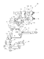
図3は実施例1の平行2軸ヒンジの斜視図である。図4は実施例1の平行2軸ヒンジの分解斜視図である。図5は第1ヒンジシャフトの説明図である。図5中、(a)は平面図、(b)は正面図、(c)は側面図である。図6は第2ヒンジシャフトの説明図である。図6中、(a)は平面図、(b)は正面図、(c)は側面図である。
(Parallel 2-axis hinge)
FIG. 3 is a perspective view of the parallel biaxial hinge of the first embodiment. FIG. 4 is an exploded perspective view of the parallel biaxial hinge of the first embodiment. FIG. 5 is an explanatory view of the first hinge shaft. In FIG. 5, (a) is a plan view, (b) is a front view , and (c) is a side view . FIG. 6 is an explanatory view of the second hinge shaft. In FIG. 6, (a) is a plan view, (b) is a front view , and (c) is a side view .

図3に示すように、平行2軸ヒンジ4は、ヒンジ部4aを有する。ヒンジ部の一例であるヒンジ部4aは、第1ヒンジシャフト10と第2ヒンジシャフト12とを平行に保持して回動自在に支持する。連動手段の一例であるヒンジ部4aは、第1ヒンジシャフト10と第2ヒンジシャフト12とが対称に回動するように、第1ヒンジシャフト10と第2ヒンジシャフト12とを連動させる。 As shown in FIG. 3, the parallel biaxial hinge 4 has a hinge portion 4a. The hinge portion 4a, which is an example of the hinge portion, holds the first hinge shaft 10 and the second hinge shaft 12 in parallel and supports them rotatably. The hinge portion 4a, which is an example of the interlocking means, interlocks the first hinge shaft 10 and the second hinge shaft 12 so that the first hinge shaft 10 and the second hinge shaft 12 rotate symmetrically.

図4に示すように、第1取付プレート11は、第1筐体2に固定可能であって、第1ヒンジシャフト10に固定されている。第1ヒンジシャフト10は、断面扁平形状の取付板部10aに取付孔10b、10bを設けてある。取付板部10aには、取付ピン10i、10iを用いて第1取付プレート11が取付けられる。ベース部材の一例である第1取付プレート11は、第1ヒンジシャフト10の端部に固定されている。第1取付プレート11は、第1取付プレート11に設けた複数の取付孔11b、11b、・・・に対して、不図示の取付ネジを用いて図2の(a)に示す第1筐体2のフレームに取付けられる。 As shown in FIG. 4, the first mounting plate 11 can be fixed to the first housing 2 and is fixed to the first hinge shaft 10. The first hinge shaft 10 is provided with mounting holes 10b and 10b in a mounting plate portion 10a having a flat cross section. The first mounting plate 11 is mounted on the mounting plate portion 10a using the mounting pins 10i and 10i. The first mounting plate 11, which is an example of the base member, is fixed to the end of the first hinge shaft 10. The first mounting plate 11 is a first housing shown in FIG. 2A by using mounting screws (not shown) for a plurality of mounting holes 11b, 11b, ... Provided in the first mounting plate 11. It is attached to the frame of 2.

第1取付プレート11は、第1ヒンジシャフト10の取付孔10b、10bと第1取付プレート11の取付孔11a、11aとを貫通させたフランジ付きの取付ピン10i、10iの端部をかしめることによって取付板部10aへ取付けられる。尚、取付ピン10i、10iはナット付きの取付ネジとしてもよい。 The first mounting plate 11 crimps the ends of the flanged mounting pins 10i and 10i that penetrate the mounting holes 10b and 10b of the first hinge shaft 10 and the mounting holes 11a and 11a of the first mounting plate 11. Is attached to the attachment plate portion 10a. The mounting pins 10i and 10i may be mounting screws with nuts.

一方、第2取付プレート13は、第2筐体3に固定可能であって、第2ヒンジシャフト12に固定されている。第2ヒンジシャフト12は、断面扁平形状の取付板部12aに取付孔12b、12bを設けてある。取付板部12aには、取付ピン12h、12hを用いて第2取付プレート13が取付けられる。第2取付プレート13は、第2取付プレート13に設けた取付孔13b、13b、・・・に対して、不図示の取付ネジを用いて図2の(a)に示す第2筐体3のフレームに取付けられる。 On the other hand, the second mounting plate 13 can be fixed to the second housing 3 and is fixed to the second hinge shaft 12. The second hinge shaft 12 is provided with mounting holes 12b and 12b in a mounting plate portion 12a having a flat cross section. The second mounting plate 13 is mounted on the mounting plate portion 12a using the mounting pins 12h and 12h. The second mounting plate 13 uses mounting screws (not shown) for the mounting holes 13b, 13b, ... Provided in the second mounting plate 13, of the second housing 3 shown in FIG. 2A. Attached to the frame.

第2取付プレート13は、第2ヒンジシャフト12の取付孔12b、12bと第2取付プレート13の取付孔13a、13aとを貫通させたフランジ付きの取付ピン12h、12hの端部をかしめることによって取付板部12aへ取付けられる。尚、取付ピン12h、12hはナット付きの取付ネジとしてもよい。 The second mounting plate 13 crimps the ends of the flanged mounting pins 12h and 12h that penetrate the mounting holes 12b and 12b of the second hinge shaft 12 and the mounting holes 13a and 13a of the second mounting plate 13. Is attached to the attachment plate portion 12a. The mounting pins 12h and 12h may be mounting screws with nuts.

図4に示すように、第1ヒンジシャフト10と第2ヒンジシャフト12とは、ヒンジケース7内に収容された回転制御部5における回転軸線方向の複数の位置で回転自在に支持されることにより、互いに平行状態に保たれている。回転制御部5は、ヒンジケース7によって位置関係を固定されたギアサポート部材15とフリクションプレート31とカムプレート部材36とにより第1ヒンジシャフト10と第2ヒンジシャフト12の平行状態を保っている。回転制御部5は、ギアサポート部材15に設けた第1A軸受孔15c、第1B軸受孔15dと、フリクションプレート31に設けた第2A軸受孔31a、第2B軸受孔31bと、カムプレート部材36に設けた第3A軸受孔36a、第3B軸受孔36bとにおいて、第1ヒンジシャフト10と第2ヒンジシャフト12とを回転可能に挿通させて回転自在に支持している。 As shown in FIG. 4, the first hinge shaft 10 and the second hinge shaft 12 are rotatably supported at a plurality of positions in the rotation axis direction in the rotation control unit 5 housed in the hinge case 7. , Are kept parallel to each other. The rotation control unit 5 maintains the parallel state of the first hinge shaft 10 and the second hinge shaft 12 by the gear support member 15, the friction plate 31 and the cam plate member 36 whose positional relationship is fixed by the hinge case 7. The rotation control unit 5 is provided in the first A bearing hole 15c and the first B bearing hole 15d provided in the gear support member 15, the second A bearing hole 31a and the second B bearing hole 31b provided in the friction plate 31, and the cam plate member 36. In the provided third A bearing hole 36a and third B bearing hole 36b, the first hinge shaft 10 and the second hinge shaft 12 are rotatably inserted and rotatably supported.

図5の(a)、(b)に示すように、第1ヒンジシャフト10は、取付板部10aに続いて設けられたフランジ部10cに続いて第1円形軸部10dが設けられている。そして、第1円形軸部10dに続いて第1円形軸部10dよりも小径の第2円形軸部10eが設けられている。第2円形軸部10eの先端側には、断面略楕円形状を呈するように加工して成る第1変形軸部10fと、この第1変形軸部10fに続いて設けられた雄ネジ部10hとが形成されている。 As shown in FIGS. 5A and 5B, the first hinge shaft 10 is provided with a first circular shaft portion 10d following the flange portion 10c provided following the mounting plate portion 10a. Then, following the first circular shaft portion 10d, a second circular shaft portion 10e having a diameter smaller than that of the first circular shaft portion 10d is provided. On the tip end side of the second circular shaft portion 10e, a first deformed shaft portion 10f processed so as to exhibit a substantially elliptical cross section, and a male screw portion 10h provided following the first deformed shaft portion 10f. Is formed.

図6の(a)、(b)に示すように、第2ヒンジシャフト12は、取付板部12aに続いて設けられたフランジ部12cに続いて円形軸部12dが設けられている。そして、円形軸部12dの先端側には、断面略楕円形状を呈するように加工して成る第1変形軸部12eと、この第1変形軸部12eに続いて設けられた雄ネジ部12gとが形成されている。 As shown in FIGS. 6A and 6B, the second hinge shaft 12 is provided with a circular shaft portion 12d following the flange portion 12c provided following the mounting plate portion 12a. Then, on the tip end side of the circular shaft portion 12d, a first deformed shaft portion 12e processed so as to exhibit a substantially elliptical cross section, and a male screw portion 12g provided following the first deformed shaft portion 12e. Is formed.

(回転制御部)
図7は回転制御部の組立状態の説明図である。図3に示すように、ベース部材の一例である第1取付プレート11は、第1ヒンジシャフト10の端部に固定されている。ヒンジ部の一例であるヒンジ部4aは、第1ヒンジシャフト10の第1取付プレート11と反対側の端部に配置され、第1ヒンジシャフト10と第2ヒンジシャフト12とを平行に保持して回動可能に支持する。
(Rotation control unit)
FIG. 7 is an explanatory diagram of an assembled state of the rotation control unit. As shown in FIG. 3, the first mounting plate 11, which is an example of the base member, is fixed to the end of the first hinge shaft 10. The hinge portion 4a, which is an example of the hinge portion, is arranged at an end portion of the first hinge shaft 10 opposite to the first mounting plate 11, and holds the first hinge shaft 10 and the second hinge shaft 12 in parallel. Supports rotatably.

図7に示すように、第1ヒンジシャフト10と第2ヒンジシャフト12とを連絡して回転制御部5が設けられている。回転制御部5は、第1ヒンジシャフト10の回転を制御する第1回転制御部5aと、第2ヒンジシャフト12の回転を制御する第2回転制御部5bと、から成る。 As shown in FIG. 7, a rotation control unit 5 is provided in contact with the first hinge shaft 10 and the second hinge shaft 12. The rotation control unit 5 includes a first rotation control unit 5a that controls the rotation of the first hinge shaft 10, and a second rotation control unit 5b that controls the rotation of the second hinge shaft 12.

図7を参照して図4に示すように、第1回転制御部5aは、同期回転部14、第1付勢部21a、第1フリクショントルク発生部30a、及び第1吸込み部35aから構成されている。そして、第1付勢部21aは、第1フリクショントルク発生部30aと第1吸込み部35とにおいてそれぞれ圧接力を作用させ、第1筐体2と第2筐体3の開閉操作時の第1ヒンジシャフト10の回転時、第1ヒンジシャフト10に対してフリクショントルク創出機能と吸込み機能を発揮させる。また、第2回転制御部5bは、同期回転部14、第2付勢部21b、第2フリクショントルク発生部30b、及び第2吸込み部35bから構成されている。そして、第2付勢部21bは、第2フリクショントルク発生部30bと第2吸込み部35とにおいてそれぞれ圧接力を作用させ、第1筐体2と第2筐体3の開閉操作時の第2ヒンジシャフト12の回転時、第2ヒンジシャフト12に対してフリクショントルク創出機能と吸込み機能を発揮させる。 As shown in FIG. 4 with reference to FIG. 7, the first rotation control unit 5a includes a synchronous rotation unit 14, a first biasing unit 21a, a first friction torque generating unit 30a, and a first suction unit 35a. ing. Then, the first urging portion 21a exerts a pressure contact force on the first friction torque generating portion 30a and the first suction portion 35, respectively, and the first housing 2 and the second housing 3 are opened and closed. When the hinge shaft 10 rotates, the first hinge shaft 10 exerts a friction torque creating function and a suction function. Further, the second rotation control unit 5b is composed of a synchronous rotation unit 14, a second urging unit 21b, a second friction torque generating unit 30b, and a second suction unit 35b. Then, the second urging portion 21b exerts a pressure contact force on the second friction torque generating portion 30b and the second suction portion 35, respectively, and the second housing 2 and the second housing 3 are opened and closed at the time of opening and closing. When the hinge shaft 12 rotates, the second hinge shaft 12 exerts a friction torque creating function and a suction function.

ここで、フリクショントルク創出機能とは、第1筐体2と第2筐体3とを自在な回動位置で停止して保持させるために必要な摩擦抵抗を発生させる機能である。また、吸込み機能とは、第1筐体2と第2筐体3とを所定の角度位置(0度及び360度)へ引き込んで保持する機能である。 Here, the friction torque creation function is a function of generating frictional resistance necessary for stopping and holding the first housing 2 and the second housing 3 at a free rotation position. The suction function is a function of pulling and holding the first housing 2 and the second housing 3 to predetermined angular positions (0 degrees and 360 degrees).

第1付勢部21aは、第1締付ナット24を締め付けて第1弾性部材22を圧縮することにより、第1フリクショントルク発生部30a及び第1吸込み部35aにおいて必要な圧力を発生させる。第1弾性部材22は、円形挿通孔22aに図5に示す第1ヒンジシャフト10の第1変形軸部10fを挿通させつつ重ねて設けられた複数枚の皿バネ、或いはスプリングワッシャから成る。第1押えワッシャ23は、第1弾性部材22に隣接配置され、中央の変形挿通孔23aに図5に示す第1ヒンジシャフト10の第1変形軸部10fを挿通係合させて組立てられる。第1締付ナット24は、第1押えワッシャ23に隣接配置され、その雌ネジ孔24aを図5に示す第1ヒンジシャフト10の雄ネジ部10hにネジ着させて組立てられる。 The first urging portion 21a compresses the first elastic member 22 by tightening the first tightening nut 24 to generate necessary pressure in the first friction torque generating portion 30a and the first suction portion 35a. The first elastic member 22 is composed of a plurality of disc springs or spring washers provided so as to insert the first deformable shaft portion 10f of the first hinge shaft 10 shown in FIG. 5 into the circular insertion hole 22a. The first presser washer 23 is arranged adjacent to the first elastic member 22, and is assembled by inserting and engaging the first deformation shaft portion 10f of the first hinge shaft 10 shown in FIG. 5 in the central deformation insertion hole 23a. The first tightening nut 24 is arranged adjacent to the first presser washer 23, and is assembled by screwing the female screw hole 24a into the male screw portion 10h of the first hinge shaft 10 shown in FIG.

第2付勢部21bは、図4に示すように、第2締付ナット27を締め付けて第2弾性部材25を圧縮することにより、第2フリクショントルク発生部30b及び第2吸込み部35bにおいて必要な圧力を発生させる。第2弾性部材25は、円形挿通孔25aに図6に示す第2ヒンジシャフト12の第1変形軸部12eを挿通させつつ重ねて設けられた複数枚の皿バネ、或いはスプリングワッシャから成る。第2押えワッシャ26は、第2弾性部材25に隣接配置され、中央の変形挿通孔26aに図6に示す第2ヒンジシャフト12の第1変形軸部12eを挿通係合させて組立てられる。第2締付ナット27は、第2押えワッシャ26に隣接配置され、その雌ネジ孔27aを図6に示す第2ヒンジシャフト12の雄ネジ部12gにネジ着させて組立てられる。 As shown in FIG. 4, the second urging portion 21b is required in the second friction torque generating portion 30b and the second suction portion 35b by tightening the second tightening nut 27 and compressing the second elastic member 25. Pressure is generated. The second elastic member 25 is composed of a plurality of disc springs or spring washers provided so as to insert the first deformable shaft portion 12e of the second hinge shaft 12 shown in FIG. 6 into the circular insertion hole 25a. The second presser washer 26 is arranged adjacent to the second elastic member 25, and is assembled by inserting and engaging the first deformable shaft portion 12e of the second hinge shaft 12 shown in FIG. 6 in the central deformable insertion hole 26a. The second tightening nut 27 is arranged adjacent to the second presser washer 26, and is assembled by screwing the female screw hole 27a into the male screw portion 12 g of the second hinge shaft 12 shown in FIG.

(同期回転部)
図8は同期回転部の構成の説明図である。図8中、(a)は同期回転部、(b)はギアサポート部材である。図8に示すように、同期回転手段の一例である同期回転部14は、回転制御部5に対して第1ヒンジシャフト10と第2ヒンジシャフト12とが対称に回動するように第1ヒンジシャフト10と第2ヒンジシャフト12とを同期回転させる。同期回転部14は、中間ギア20により第1ヒンジシャフト10と第2ヒンジシャフト12とを同期させて回転制御部5に対して対称に回動させる。
(Synchronous rotating part)
FIG. 8 is an explanatory diagram of the configuration of the synchronous rotating unit. In FIG. 8, (a) is a synchronous rotating part, and (b) is a gear support member. As shown in FIG. 8 , the synchronous rotation unit 14, which is an example of the synchronous rotation means, has a first hinge such that the first hinge shaft 10 and the second hinge shaft 12 rotate symmetrically with respect to the rotation control unit 5. The shaft 10 and the second hinge shaft 12 are rotated synchronously. The synchronous rotation unit 14 synchronizes the first hinge shaft 10 and the second hinge shaft 12 with the intermediate gear 20 and rotates them symmetrically with respect to the rotation control unit 5.

図8に示すように、ギアサポート部材15は、下部突出部15aに第1A軸受孔15cを有し、上部突出部15bに第1B軸受孔15dを有する。第1A軸受孔15cは、図5に示す第1ヒンジシャフト10の第2円形軸部10eを回転自在に挿通させる。第1B軸受孔15dは、図6に示す第2ヒンジシャフト12の円形軸部12dを回転自在に挿通させる。 As shown in FIG. 8, the gear support member 15 has a first A bearing hole 15c in the lower protruding portion 15a and a first B bearing hole 15d in the upper protruding portion 15b. The first A bearing hole 15c is rotatably inserted into the second circular shaft portion 10e of the first hinge shaft 10 shown in FIG. The first B bearing hole 15d is rotatably inserted through the circular shaft portion 12d of the second hinge shaft 12 shown in FIG.

ギアサポート部材15の下部突出部15aに設けた第1軸支溝15eと上部突出部15bに設けた第2軸支溝15fとに、中間ギア20の下部支軸20aと上部支軸20bとがそれぞれ回転可能に挿入支持される。中間ギア20は、下部に下部傘歯部20cを有し、上部に上部傘歯部20dを有する。 The lower support shaft 20a and the upper support shaft 20b of the intermediate gear 20 are formed in the first shaft support groove 15e provided in the lower protrusion 15a of the gear support member 15 and the second shaft support groove 15f provided in the upper protrusion 15b. Each is rotatably inserted and supported. The intermediate gear 20 has a lower umbrella tooth portion 20c at the lower portion and an upper umbrella tooth portion 20d at the upper portion.

第1ギア17と第2ギア18とは同一部品である。第1ギア17は、図5に示す第1ヒンジシャフト10の第1変形軸部10fに、その中心部軸方向に設けた変形挿通孔17aを挿通係合させた傘歯車から成る。第1ギア17は、中間ギア20の下部傘歯部20cに噛合する。第2ギア18は、図6に示す第2ヒンジシャフト12の第1変形軸部12eに、その中心部軸方向に設けた変形挿通孔18aを挿通係合させた傘歯車から成る。第2ギア18は、中間ギア20の上部傘歯部20dに噛合する。 The first gear 17 and the second gear 18 are the same parts. The first gear 17 is composed of a bevel gear in which a deformation insertion hole 17a provided in the axial direction of the central portion is inserted and engaged with the first deformation shaft portion 10f of the first hinge shaft 10 shown in FIG. The first gear 17 meshes with the lower umbrella tooth portion 20c of the intermediate gear 20. The second gear 18 is composed of a bevel gear in which a deformation insertion hole 18a provided in the axial direction of the central portion is inserted and engaged with the first deformation shaft portion 12e of the second hinge shaft 12 shown in FIG. The second gear 18 meshes with the upper umbrella tooth portion 20d of the intermediate gear 20.

ワッシャ62、63は、潤滑性の樹脂で形成され、第1ギア17、第2ギア18とギアサポート部材15の間の摩擦を軽減する。 The washers 62 and 63 are made of a lubricating resin to reduce friction between the first gear 17, the second gear 18 and the gear support member 15.

(フリクショントルク発生部)
図9はフリクションプレートの構造の説明図である。図10はカムプレート部材の構造の説明図である。図11は第1フリクションワッシャ及び第2フリクションワッシャの構造の説明図である。図9中、(a)は同期回転部側の面、(b)は第1付勢部側の面である。図10中、(a)は斜視図、(b)は第1付勢部側の面、(c)は同期回転部側の面である。図11中、(a)は第1付勢部側の面、(b)は同期回転部側の面である。
(Friction torque generator)
FIG. 9 is an explanatory diagram of the structure of the friction plate. FIG. 10 is an explanatory view of the structure of the cam plate member. FIG. 11 is an explanatory diagram of the structures of the first friction washer and the second friction washer. In FIG. 9, (a) is a surface on the synchronous rotating portion side, and (b) is a surface on the first urging portion side. In FIG. 10, (a) is a perspective view, (b) is a surface on the first urging portion side, and (c) is a surface on the synchronous rotating portion side. In FIG. 11, (a) is a surface on the first urging portion side, and (b) is a surface on the synchronous rotating portion side.

図7に示すように、フリクショントルク発生部30は、第1ヒンジシャフト10と第2ヒンジシャフト12の回動時に同時に動作してフリクショントルクを発生させ、図2に示す第1筐体2と第2筐体3の開閉動作時の任意の角度における安定停止作用を行うものである。フリクショントルク発生部30は、同期回転部14と吸込み部35との間に配置され、図4に示すように、下側の第1フリクショントルク発生部30aと上側の第2フリクショントルク発生部30bとから構成されている。 As shown in FIG. 7, the friction torque generating unit 30 operates at the same time when the first hinge shaft 10 and the second hinge shaft 12 rotate to generate friction torque, and the first housing 2 and the second hinge shaft 12 shown in FIG. 2 are generated. 2 It performs a stable stop action at an arbitrary angle when the housing 3 is opened and closed. The friction torque generating unit 30 is arranged between the synchronous rotating unit 14 and the suction unit 35, and as shown in FIG. 4, the friction torque generating unit 30 is the lower first friction torque generating unit 30a and the upper second friction torque generating unit 30b. It is composed of.

第1フリクショントルク発生部30aは、第1弾性部材22により加圧されたフリクションプレート31、第1フリクションワッシャ32、及びカムプレート部材36の間でフリクショントルクを創成させる。フリクションプレート31は、下部側の第2A軸受孔31aに図5に示す第1ヒンジシャフト10の第1変形軸部10fを回転自在に挿通させている。フリクションプレート31は、図9の(b)に示すように第1付勢部21a側の面に摩擦面であるナナコメ加工部31dが形成されて耐久性の向上が図られている。また、カムプレート部材36は、下部側の第3A軸受孔36aに図5に示す第1ヒンジシャフト10の第1変形軸部10fを回転自在に挿通させている。カムプレート部材36は、図10の(c)に示すように第1付勢部21a側の面に滑らかな凹凸面であるナナコメ加工部36gが形成されて耐久性の向上が図られている。 The first friction torque generating unit 30a creates friction torque between the friction plate 31, the first friction washer 32, and the cam plate member 36 pressurized by the first elastic member 22. In the friction plate 31, the first deformable shaft portion 10f of the first hinge shaft 10 shown in FIG. 5 is rotatably inserted into the second A bearing hole 31a on the lower side. As shown in FIG. 9B, the friction plate 31 has a friction surface formed on the surface on the side of the first urging portion 21a to improve the durability. Further, in the cam plate member 36, the first deformable shaft portion 10f of the first hinge shaft 10 shown in FIG. 5 is rotatably inserted into the third A bearing hole 36a on the lower side. As shown in FIG. 10 (c), the cam plate member 36 has a smooth uneven surface formed on the surface on the side of the first urging portion 21a, that is, a nana rice processed portion 36 g, to improve the durability.

第1フリクションワッシャ32は、フリクションプレート31の第1付勢部21a側の面に重ねて配置される。第1フリクションワッシャ32は、中央の第1変形挿通孔32aに対して図5に示す第1ヒンジシャフト10の第1変形軸部10fを挿通して係合させている。第1フリクションワッシャ32は、図11に示すように、両側の面32b、32cに摩擦面が形成されている。このため、第1付勢部21aにより加圧された状態での第1ヒンジシャフト10の回転に伴って、フリクションプレート31と第1フリクションワッシャ32との対向面間、及び第1フリクションワッシャ32とカムプレート部材36との対向面間に摩擦が発生する。なお、図9の(a)に示すように、フリクションプレート31の同期回転部14側の面は、摩擦係数の低い樹脂材料で平坦に形成され、相対回転する第1ギア17との間の摩擦を低減させてある。 The first friction washer 32 is arranged so as to overlap the surface of the friction plate 31 on the first urging portion 21a side. The first friction washer 32 is engaged with the first deformation insertion hole 32a at the center by inserting the first deformation shaft portion 10f of the first hinge shaft 10 shown in FIG. As shown in FIG. 11, the first friction washer 32 has friction surfaces formed on the surfaces 32b and 32c on both sides. Therefore, as the first hinge shaft 10 rotates under pressure from the first urging portion 21a, the friction plate 31 and the first friction washer 32 face each other, and the first friction washer 32 and the friction plate 31 Friction is generated between the surfaces facing the cam plate member 36. As shown in FIG. 9A, the surface of the friction plate 31 on the synchronous rotating portion 14 side is formed flat with a resin material having a low friction coefficient, and the friction between the friction plate 31 and the relative rotating first gear 17 is formed. Is reduced.

第2フリクショントルク発生部30bは、第1弾性部材22により加圧されたフリクションプレート31、第1フリクションワッシャ32、及びカムプレート部材36の間でフリクショントルクを創成させる。フリクションプレート31は、上部側の第2B軸受孔31bに図5に示す第2ヒンジシャフト12の第1変形軸部12eを回転自在に挿通させている。フリクションプレート31は、図9の(b)に示すように付勢部21側の面に摩擦面であるナナコメ加工部31fが形成されて耐久性の向上が図られている。また、カムプレート部材36は、上部側の第3B軸受孔36bに図6に示す第2ヒンジシャフト12の第1変形軸部10eを回転自在に挿通させている。カムプレート部材36は、図10の(c)に示すように第1付勢部21a側の面に滑らかな凹凸面であるナナコメ加工部36hが形成されて耐久性の向上が図られている。 The second friction torque generating unit 30b creates friction torque between the friction plate 31, the first friction washer 32, and the cam plate member 36 pressurized by the first elastic member 22. In the friction plate 31, the first deformable shaft portion 12e of the second hinge shaft 12 shown in FIG. 5 is rotatably inserted into the second B bearing hole 31b on the upper side. As shown in FIG. 9B, the friction plate 31 is improved in durability by forming a friction surface, a nana rice processing portion 31f, on the surface on the side of the urging portion 21. Further, in the cam plate member 36, the first deformable shaft portion 10e of the second hinge shaft 12 shown in FIG. 6 is rotatably inserted into the third B bearing hole 36b on the upper side. As shown in FIG. 10 (c), the cam plate member 36 has a smooth uneven surface formed on the surface on the side of the first urging portion 21a, which is a smooth uneven surface, and the durability of the cam plate member 36 is improved.

第2フリクションワッシャ33は、フリクションプレート31の付勢部21側の面に重ねて配置される。第2フリクションワッシャ33は、中央の第1変形挿通孔33aに対して図6に示す第2ヒンジシャフト12の第1変形軸部10eを挿通して係合させている。第2フリクションワッシャ33は、図11に示すように、両側の面32b、32cに摩擦面が形成されている。このため、第2付勢部21bにより加圧された状態での第2ヒンジシャフト12の回転に伴って、フリクションプレート31と第2フリクションワッシャ32との対向面間、及び第2フリクションワッシャ32とカムプレート部材36との対向面間に摩擦が発生する。なお、図9の(a)に示すように、フリクションプレート31の同期回転部14側の面は、摩擦係数の低い樹脂材料で平坦に形成され、相対回転する第2ギア18との間の摩擦を低減させてある。 The second friction washer 33 is arranged so as to overlap the surface of the friction plate 31 on the urging portion 21 side. The second friction washer 33 is engaged with the first deformation insertion hole 33a at the center by inserting the first deformation shaft portion 10e of the second hinge shaft 12 shown in FIG. As shown in FIG. 11, the second friction washer 33 has friction surfaces formed on the surfaces 32b and 32c on both sides. Therefore, as the second hinge shaft 12 rotates under pressure by the second urging portion 21b, the friction plate 31 and the second friction washer 32 face each other, and the second friction washer 32 and the second friction washer 32 Friction is generated between the surfaces facing the cam plate member 36. As shown in FIG. 9A, the surface of the friction plate 31 on the synchronous rotating portion 14 side is formed flat with a resin material having a low coefficient of friction, and friction with the second gear 18 that rotates relative to each other. Is reduced.

(吸込み部)
図12は第1カムフォロワ及び第2カムフォロワの構造の説明図である。図7に示すように、吸込み部35は、フリクショントルク発生部30と付勢部21との間に配置される。吸込み部35は、図2に示す第1筐体2と第2筐体3との開成角度が0度の閉状態において、第1筐体2と第2筐体3の間にラッチ機構を設けなくとも、自然に第1筐体2から第2筐体3が開いてしまうことなく閉成状態を保持する。さらに、第1筐体2と第2筐体3との開成角度が360度の反転状態において、第1筐体2と第2筐体3との間にラッチ機構を設けなくとも、自然に第1筐体2から第2筐体3が浮き上がることなく反転状態を保持させる。
(Suction part)
FIG. 12 is an explanatory diagram of the structures of the first cam follower and the second cam follower. As shown in FIG. 7, the suction portion 35 is arranged between the friction torque generating portion 30 and the urging portion 21. The suction unit 35 is provided with a latch mechanism between the first housing 2 and the second housing 3 in a closed state where the opening angle between the first housing 2 and the second housing 3 shown in FIG. 2 is 0 degrees. Even if it is not, the closed state is maintained without the first housing 2 to the second housing 3 opening naturally. Further, in an inverted state where the opening angle between the first housing 2 and the second housing 3 is 360 degrees, the first housing 2 and the second housing 3 do not need to be provided with a latch mechanism. The inverted state is maintained without the second housing 3 rising from the first housing 2.

図7を参照して図4に示すように、吸込み部35は、第1ヒンジシャフト10側の第1吸込み部35aと、第2ヒンジシャフト12側の第2吸込み部35bとから構成されている。第1吸込み部35aは、第1付勢部21aにより加圧されたカムプレート部材36と第1カムフォロワ37とで構成される。第1カムフォロワ37は、第1ヒンジシャフト10に回転を拘束されているが、第1ヒンジシャフト10の回転軸線方向にスライド可能である。 As shown in FIG. 4 with reference to FIG. 7, the suction portion 35 is composed of a first suction portion 35a on the first hinge shaft 10 side and a second suction portion 35b on the second hinge shaft 12 side. .. The first suction portion 35a is composed of a cam plate member 36 pressurized by the first urging portion 21a and a first cam follower 37. Although the rotation of the first cam follower 37 is restricted by the first hinge shaft 10, it can slide in the direction of the rotation axis of the first hinge shaft 10.

カムプレート部材36は、下部側の第3A軸受孔36aに図5に示す第1ヒンジシャフト10の第1変形軸部10fを回転自在に挿通させている。第1カムフォロワ37は、その変形挿通孔37aへ第1ヒンジシャフト10の第1変形軸部10fを挿通して係合させることによって回転を拘束されている。このため、第1付勢部21aにより加圧された状態での第1ヒンジシャフト10の回転に伴ってカムプレート部材36と第1カムフォロワ37との当接面に相対回転が発生する。 The cam plate member 36 rotatably inserts the first deformable shaft portion 10f of the first hinge shaft 10 shown in FIG. 5 into the third A bearing hole 36a on the lower side. The rotation of the first cam follower 37 is restricted by inserting and engaging the first deformation shaft portion 10f of the first hinge shaft 10 with the deformation insertion hole 37a. Therefore, as the first hinge shaft 10 rotates under pressure from the first urging portion 21a, relative rotation occurs on the contact surface between the cam plate member 36 and the first cam follower 37.

カムプレート部材36の第1カムフォロワ37に対する対向面には、図10に示すように、その外周面側に略円弧状の第1Aカム凹部36cが形成され、第1Aカム凹部36cの内側に略円弧状の第1Bカム凹部36dが形成されている。第1カムフォロワ37のカムプレート部材36に対する対向面には、図12に示すように、その外周面側に略円弧状の第1Aカム凸部37cが形成され、第1Aカム凸部37cの内側に略円弧状の第1Bカム凸部37bが形成されている。 As shown in FIG. 10, a substantially arc-shaped first A cam recess 36c is formed on the outer peripheral surface side of the cam plate member 36 facing the first cam follower 37, and a substantially circular circle is formed inside the first A cam recess 36c. An arc-shaped first B cam recess 36d is formed. As shown in FIG. 12, a substantially arcuate first A cam convex portion 37c is formed on the outer peripheral surface side of the first cam follower 37 facing the cam plate member 36, and inside the first A cam convex portion 37c. A substantially arc-shaped first B cam convex portion 37b is formed.

このため、カムプレート部材36と第1カムフォロワ37との間に相対回転が発生すると、第1Aカム凹部36cと第1Aカム凸部37cとの間、及び第1Bカム凹部36dと第1Bカム凸部37bとの間でそれぞれ押し上げと押し下げとが発生して、カムプレート部材36と第1カムフォロワ37とが重なり合った合計の厚みが変化する。 Therefore, when a relative rotation occurs between the cam plate member 36 and the first cam follower 37, the relative rotation occurs between the first A cam concave portion 36c and the first A cam convex portion 37c, and between the first B cam concave portion 36d and the first B cam convex portion. Push-up and push-down occur between the cam plate member 36 and the first cam follower 37, respectively, and the total thickness of the cam plate member 36 and the first cam follower 37 is changed.

第2吸込み部35bは、第2付勢部21bにより加圧されたカムプレート部材36と第2カムフォロワ38とで構成される。図4に示すように、第2カムフォロワ38は、第2ヒンジシャフト12に回転を拘束されているが、第2ヒンジシャフト12の回転軸線方向にスライド可能である。 The second suction portion 35b is composed of a cam plate member 36 pressurized by the second urging portion 21b and a second cam follower 38. As shown in FIG. 4, the second cam follower 38 is restricted in rotation by the second hinge shaft 12, but can slide in the direction of the rotation axis of the second hinge shaft 12.

カムプレート部材36は、上部側の第3B軸受孔36bに図6に示す第2ヒンジシャフト12の第1変形軸部12eを回転自在に挿通させている。第2カムフォロワ38は、その変形挿通孔38aへ第2ヒンジシャフト12の第1変形軸部12eを挿通して係合させることによって回転を拘束されている。このため、第2付勢部21bにより加圧された状態での第2ヒンジシャフト12の回転に伴ってカムプレート部材36と第2カムフォロワ38との当接面に相対回転が発生する。 In the cam plate member 36, the first deformable shaft portion 12e of the second hinge shaft 12 shown in FIG. 6 is rotatably inserted into the third B bearing hole 36b on the upper side. The rotation of the second cam follower 38 is restricted by inserting and engaging the first deformed shaft portion 12e of the second hinge shaft 12 with the deformed insertion hole 38a. Therefore, as the second hinge shaft 12 rotates under pressure from the second urging portion 21b, relative rotation occurs on the contact surface between the cam plate member 36 and the second cam follower 38.

カムプレート部材36の第2カムフォロワ38に対する対向面には、図10に示すように、その外周面側に略円弧状の第2Aカム凹部36eが形成され、第2Aカム凹部36eの内側に略円弧状の第2Bカム凹部36fが形成されている。第2カムフォロワ38のカムプレート部材36に対する対向面には、図12に示すように、その外周面側に略円弧状の第2Aカム凸部38cが形成され、第2Aカム凸部38cの内側に略円弧状の第2Bカム凸部38bが形成されている。 As shown in FIG. 10, a substantially arcuate second A cam recess 36e is formed on the outer peripheral surface side of the cam plate member 36 facing the second cam follower 38, and a substantially circular circle is formed inside the second A cam recess 36e. An arc-shaped second B cam recess 36f is formed. As shown in FIG. 12, a substantially arcuate second A cam convex portion 38c is formed on the outer peripheral surface side of the second cam follower 38 with respect to the cam plate member 36, and inside the second A cam convex portion 38c. A substantially arc-shaped second B cam convex portion 38b is formed.

このため、カムプレート部材36と第2カムフォロワ38との間に相対回転が発生すると、第2Aカム凹部36eと第2Aカム凸部38cとの間、及び第2Bカム凹部36fと第2Bカム凸部38bとの間でそれぞれ押し上げと押し下げとが発生して、カムプレート部材36と第1カムフォロワ37とが重なり合った合計の厚みが変化する。 Therefore, when a relative rotation occurs between the cam plate member 36 and the second cam follower 38, between the second A cam concave portion 36e and the second A cam convex portion 38c, and between the second B cam concave portion 36f and the second B cam convex portion. Pushing up and pushing down occur with 38b, respectively, and the total thickness of the cam plate member 36 and the first cam follower 37 overlapping with each other changes.

ここで、第1ヒンジシャフト10と第2ヒンジシャフト12との開成角度が0度と360度となる回動位置で、第1カムフォロワ37及び第2カムフォロア38とカムプレート部材36との厚みがいずれも最小となって、付勢部21による加圧力が最小となる。また、第1ヒンジシャフト10と第2ヒンジシャフト10との開成角度が150度−210度の回動位置で、第1カムフォロワ37及び第2カムフォロア38とカムプレート部材36との厚みがいずれも最大となって、付勢部21による加圧力が最大となる。 Here, at the rotation positions where the opening angles of the first hinge shaft 10 and the second hinge shaft 12 are 0 degrees and 360 degrees, the thicknesses of the first cam follower 37, the second cam follower 38, and the cam plate member 36 are any longer. Is also minimized, and the pressing force by the urging portion 21 is minimized. Further, the thickness of the first cam follower 37, the second cam follower 38, and the cam plate member 36 is the maximum at the rotation position where the opening angle between the first hinge shaft 10 and the second hinge shaft 10 is 150 ° -210 °. Therefore, the pressing force by the urging unit 21 becomes maximum.

そして、第1ヒンジシャフト10と第2ヒンジシャフト10との開成角度が0度及び360度の近傍となる回動位置では、第1Aカム凹部36eと第1Aカム凸部37cの傾斜面同士、及び第1Bカム凹部36fと第1Bカム凸部37bの傾斜面同士が当接して開成角度が0度及び360度の近傍となる回動位置へ向かって滑り落ちる状態となる。このとき、図1に示す第1筐体2と第2筐体3とは、開成角度が0度と360度となる回動位置へ自動的に移動して、開成角度が0度と360度となる回動位置で安定的に保持される。 Then, at the rotation position where the opening angles of the first hinge shaft 10 and the second hinge shaft 10 are close to 0 degrees and 360 degrees, the inclined surfaces of the first A cam recess 36e and the first A cam convex portion 37c, and the inclined surfaces of the first A cam convex portion 37c, and The inclined surfaces of the first B cam concave portion 36f and the first B cam convex portion 37b come into contact with each other and slide down toward the rotation position where the opening angles are close to 0 degrees and 360 degrees. At this time, the first housing 2 and the second housing 3 shown in FIG. 1 automatically move to the rotation positions where the opening angles are 0 degrees and 360 degrees, and the opening angles are 0 degrees and 360 degrees. It is stably held at the rotation position.

(ヒンジケース)
図13はヒンジケースの構造の説明図である。図7に示すように、ヒンジ部4aには、ヒンジケース7が取付けられている。ヒンジケース7は、断面長孔形状を示した筒状のものであって、回転制御部5の同期回転部14と、フリクショントルク発生部30と、吸込み部35と、付勢部21と、作動機構50の一部である軸方向駆動部53と、を収容する。図4に示すように、ヒンジケース7は、取付ネジ39を用いてカムプレート部材36に設けた雌ネジ孔36iに取付けられる。
(Hinge case)
FIG. 13 is an explanatory view of the structure of the hinge case. As shown in FIG. 7, a hinge case 7 is attached to the hinge portion 4a. The hinge case 7 has a tubular shape showing a long hole shape in cross section, and operates with the synchronous rotation unit 14 of the rotation control unit 5, the friction torque generating unit 30, the suction unit 35, and the urging unit 21. It accommodates an axial drive unit 53, which is a part of the mechanism 50. As shown in FIG. 4, the hinge case 7 is attached to the female screw hole 36i provided in the cam plate member 36 by using the attachment screw 39.

図13に示すように、ヒンジケース7は、その内部に、その中央部を横切って取付筒部7aを設けた取付部7bが設けられている。カムプレート部材36は、取付部7bに設けた取付筒部7aを介してヒンジケース7に固定されている。ヒンジケース7の下部収容部7cには、図4に示す同期回転部14と、第1フリクショントルク発生部30aと、第1吸込み部35aと、第1付勢部21aとが収容される。ヒンジケース7の上部収容部7dには、図4に示す同期回転部14と、第2フリクショントルク発生部30bと、第2吸込み部35bと、第2付勢部21bとが収容される。 As shown in FIG. 13, the hinge case 7 is provided with a mounting portion 7b having a mounting cylinder portion 7a across the central portion thereof. The cam plate member 36 is fixed to the hinge case 7 via a mounting cylinder portion 7a provided on the mounting portion 7b. The lower accommodating portion 7c of the hinge case 7 accommodates the synchronous rotating portion 14 shown in FIG. 4, the first friction torque generating portion 30a, the first suction portion 35a, and the first urging portion 21a. The synchronous rotating portion 14 shown in FIG. 4, the second friction torque generating portion 30b, the second suction portion 35b, and the second urging portion 21b are accommodated in the upper accommodating portion 7d of the hinge case 7.

図1の(b)に示すように、もう一方の2軸ヒンジ6のヒンジケース8もヒンジケース7と同じ構成である。平行2軸ヒンジ4、6で連結された第1筐体2には、平行2軸ヒンジ4、6を収容させる取付凹部2b、2bが設けられ、第2筐体3には、平行2軸ヒンジ4、6を収容させる取付凹部3b、3bが設けられている。ノートパソコン1の第1筐体2と第2筐体3とを閉じた際には、ヒンジケース7は、第1筐体2に設けた取付凹部2b内と第2筐体3に設けた取付凹部3b内とに収容されている。 As shown in FIG. 1B, the hinge case 8 of the other biaxial hinge 6 has the same configuration as the hinge case 7. The first housing 2 connected by the parallel biaxial hinges 4 and 6 is provided with mounting recesses 2b and 2b for accommodating the parallel biaxial hinges 4 and 6, and the second housing 3 is provided with the parallel biaxial hinges 3. Mounting recesses 3b and 3b for accommodating 4 and 6 are provided. When the first housing 2 and the second housing 3 of the notebook computer 1 are closed, the hinge case 7 is mounted in the mounting recess 2b provided in the first housing 2 and in the second housing 3. It is housed in the recess 3b.

ヒンジケース7、8があると、平行2軸ヒンジ4、6をノートパソコン1へ取付けた際に、後述する内部の同期回転部14、フリクショントルク発生部30、及び吸込み部35等が外部へ露出しないので、平行2軸ヒンジ4、6が外観上すっきりとしたものになる。 With the hinge cases 7 and 8, when the parallel biaxial hinges 4 and 6 are attached to the notebook computer 1, the internal synchronous rotating portion 14, the friction torque generating portion 30, the suction portion 35, etc., which will be described later, are exposed to the outside. Therefore, the parallel biaxial hinges 4 and 6 are neat in appearance.

(作動機構)
図14は作動機構の構成の説明図である。図3に示すように、平行2軸ヒンジ4は、第1筐体2側に取り付けられる第1ヒンジシャフト10と、第2筐体3側に取り付けられる第2ヒンジシャフト12とを、同期回転部14を介して相対的に回動させるヒンジ部4aと、ヒンジ部4aの回動動作に伴って所定の操作出力が取出される受動操作部の一例である軸方向駆動部53と、を有する。そして、軸方向駆動部53は、第1ヒンジシャフト10と一体に回動するように設けられた第1取付プレート11と、ヒンジ部4aに設けられ、ヒンジ部4aの回動動作に伴って第2ヒンジシャフト12に対して回動するフォロア部材52と、フォロア部材52に係合する被係合部を外周面に有し、第1ヒンジシャフト10に外挿して第1取付プレート11に対して移動可能に設けられたカム部材51と、で構成される。カム部材51は、ヒンジ部4aの回動動作に伴って被係合部をフォロア部材52に案内されて第1ヒンジシャフト10の回転軸線方向に移動する。被係合部については後述する。
(Operating mechanism)
FIG. 14 is an explanatory diagram of the configuration of the operating mechanism. As shown in FIG. 3, the parallel biaxial hinge 4 has a first hinge shaft 10 attached to the first housing 2 side and a second hinge shaft 12 attached to the second housing 3 side in a synchronous rotating portion. It has a hinge portion 4a that is relatively rotated via 14, and an axial drive portion 53 that is an example of a passive operation portion from which a predetermined operation output is taken out in association with the rotation operation of the hinge portion 4a. The axial drive unit 53 is provided on the first mounting plate 11 provided so as to rotate integrally with the first hinge shaft 10 and on the hinge portion 4a, and is provided with the rotation operation of the hinge portion 4a . 2 A follower member 52 that rotates with respect to the hinge shaft 12 and an engaged portion that engages with the follower member 52 are provided on the outer peripheral surface, and are externally attached to the first hinge shaft 10 with respect to the first mounting plate 11. It is composed of a cam member 51 provided so as to be movable. The cam member 51 moves in the direction of the rotation axis of the first hinge shaft 10 by being guided by the follower member 52 as the hinge portion 4a rotates. The engaged portion will be described later.

平行2軸ヒンジ4は、図2に示す沈込み機構40を駆動してキーボード部2aを昇降させる作動機構50を有する。作動機構50は、受動操作部の一例である軸方向駆動部53によって取出した第1ヒンジシャフト10の回転軸線方向の移動を、増幅機構の一例である増幅機構60により増幅して、第1取付プレート11上の長穴11cに沿った出力部材65の直線移動として出力する。 The parallel biaxial hinge 4 has an operating mechanism 50 that drives the sinking mechanism 40 shown in FIG. 2 to raise and lower the keyboard portion 2a. The operating mechanism 50 amplifies the movement of the first hinge shaft 10 in the rotation axis direction taken out by the axial drive unit 53, which is an example of the passive operation unit, by the amplification mechanism 60, which is an example of the amplification mechanism, and first attaches the hinge shaft 10. It is output as a linear movement of the output member 65 along the elongated hole 11c on the plate 11.

図14に示すように、軸方向駆動部53は、フォロア部材52にカム部材51を係合させた状態で、カム部材51に対してフォロア部材52が回動することにより、外挿移動部材の一例であるカム部材51が、被係合部の一例であるカム溝51bに案内されて、第1ヒンジシャフト10の回転軸線方向に移動する。 As shown in FIG. 14, the axial drive unit 53 is a member of the extrapolation movement member when the follower member 52 rotates with respect to the cam member 51 in a state where the cam member 51 is engaged with the follower member 52. The cam member 51, which is an example, is guided by the cam groove 51b, which is an example of the engaged portion, and moves in the direction of the rotation axis of the first hinge shaft 10.

増幅機構60は、レバー部材61の一端の長穴61bに、カム部材51から第1ヒンジシャフト10の回転軸線方向の移動を入力されることにより、レバー部材61の他端の長穴61cに保持された出力部材65を長穴11cに沿って直線移動させる。 The amplification mechanism 60 is held in the long hole 61c at the other end of the lever member 61 by inputting the movement of the first hinge shaft 10 in the rotation axis direction from the cam member 51 into the long hole 61b at one end of the lever member 61. The output member 65 is linearly moved along the elongated hole 11c.

係合部材の一例であるフォロア部材52は、回転制御部5に設けられている。フォロア部材52は、第2ヒンジシャフト12を軸受孔52aに挿通して配置され、円形軸部12dの周りで回動可能であるが、フランジ部12cとギアサポート部材15とに挟まれて回転軸線方向の移動を規制されている。 The follower member 52, which is an example of the engaging member, is provided in the rotation control unit 5. The follower member 52 is arranged by inserting the second hinge shaft 12 through the bearing hole 52a and is rotatable around the circular shaft portion 12d, but is sandwiched between the flange portion 12c and the gear support member 15 and has a rotation axis. Directional movement is restricted.

フォロア部材52とギアサポート部材15とは、一対の係合凹所52hに一対の係合凸部15hをそれぞれ係合させて組立てられ、一体の部品として円形軸部12dの周りを回動する。図4に示すように、六角穴付きボルト19のネジ部19aをフォロア部材52の貫通孔52iに貫通させてギアサポート部材15の雌ネジ15iにネジ着している。 The follower member 52 and the gear support member 15 are assembled by engaging the pair of engaging protrusions 15h with the pair of engaging recesses 52h, respectively, and rotate around the circular shaft portion 12d as an integral part. As shown in FIG. 4, the screw portion 19a of the hexagon socket head cap screw 19 is passed through the through hole 52i of the follower member 52 and screwed to the female screw 15i of the gear support member 15.

図3を参照して図14に示すように、カム部材51は、弾性部材54によって矢印E方向に付勢されている。カム部材51は、第1ヒンジシャフト10を挿通して配置され、第1円形軸部10dの周りで回動可能、かつ、第1円形軸部10dに沿って、フランジ部10cと潤滑部材58との間で回転軸線方向に移動可能である。潤滑部材58は、第1ヒンジシャフト10の第2円形軸部10eの周りで回転自在であって、第1円形軸部10dの端面とギアサポート部材15とに挟まれて、第1円形軸部10dとギアサポート部材15の間の摩擦を軽減している。 As shown in FIG. 14 with reference to FIG. 3, the cam member 51 is urged by the elastic member 54 in the direction of arrow E. The cam member 51 is arranged by inserting the first hinge shaft 10, is rotatable around the first circular shaft portion 10d, and is formed by the flange portion 10c and the lubricating member 58 along the first circular shaft portion 10d. It is possible to move in the direction of the rotation axis between the two. The lubricating member 58 is rotatable around the second circular shaft portion 10e of the first hinge shaft 10, is sandwiched between the end face of the first circular shaft portion 10d and the gear support member 15, and is sandwiched between the first circular shaft portion 10e. The friction between 10d and the gear support member 15 is reduced.

カム部材51は、環状の円筒部51aの矢印F側の一端部に一対のガイド板51cを設けられている。ガイド板51cの矢印E方向側の部分では、図7に示すヒンジケース7との干渉を回避するために、ガイド板51cと円筒部51aとの間に隙間51iが設けられている。ヒンジケース7は、隙間51iに進入して、フォロア部材52とカム部材51の円筒部51aとを、外側から保持して回転制御部5に一体化させている。 The cam member 51 is provided with a pair of guide plates 51c at one end of the annular cylindrical portion 51a on the arrow F side. In the portion of the guide plate 51c on the arrow E direction side, a gap 51i is provided between the guide plate 51c and the cylindrical portion 51a in order to avoid interference with the hinge case 7 shown in FIG. The hinge case 7 enters the gap 51i and holds the follower member 52 and the cylindrical portion 51a of the cam member 51 from the outside and integrates them with the rotation control unit 5.

一対のガイド板51cの間にガイド間隔51dが形成されている。ガイド間隔51dは、取付穴51g、51hと第1取付プレート11の長穴11d、11eとが重なり合う位置で第1取付プレート11を挟み込む。ガイド間隔51dは、長穴11d、11eの長さの範囲で第1取付プレート11を矢印E、F方向へ移動自在に保持する。 A guide interval 51d is formed between the pair of guide plates 51c. The guide spacing 51d sandwiches the first mounting plate 11 at a position where the mounting holes 51g and 51h and the elongated holes 11d and 11e of the first mounting plate 11 overlap. The guide interval 51d holds the first mounting plate 11 movably in the directions of arrows E and F within the range of the lengths of the elongated holes 11d and 11e.

図4に示すように、第1取付プレート11とカム部材51とは、スライドピン56、57を用いて組立てられている。スライドピン57は、取付穴51gと第1取付プレート11の長穴11dとを貫通させて、ネジ部57aをカム部材51側の雌ネジにネジ着される。スライドピン56は、取付穴51hと第1取付プレート11の長穴11eとを貫通させて、ネジ部56aをカム部材51側の雌ネジにネジ着される。 As shown in FIG. 4, the first mounting plate 11 and the cam member 51 are assembled using slide pins 56 and 57. The slide pin 57 penetrates the mounting hole 51g and the elongated hole 11d of the first mounting plate 11, and the screw portion 57a is screwed to the female screw on the cam member 51 side. The slide pin 56 penetrates the mounting hole 51h and the elongated hole 11e of the first mounting plate 11, and the screw portion 56a is screwed to the female screw on the cam member 51 side.

図3に示すように、弾性部材54は、カム部材51を矢印E方向へ付勢する引張りコイルばねである。カム部材51は、弾性部材54の付勢力に加勢されつつ矢印E方向へ移動し、弾性部材54の付勢力に抗しつつ矢印F方向へ移動する。図4に示すように、弾性部材54の一端54bは、第1取付プレート11の雌ネジ11iにネジ着された係合部材55に係合されて、第1取付プレート11に固定されている。一方、弾性部材54の他端54aは、スライドピン56に係合してカム部材51と一体に移動する。 As shown in FIG. 3, the elastic member 54 is a tension coil spring that urges the cam member 51 in the direction of arrow E. The cam member 51 moves in the direction of arrow E while being urged by the urging force of the elastic member 54, and moves in the direction of arrow F while resisting the urging force of the elastic member 54. As shown in FIG. 4, one end 54b of the elastic member 54 is engaged with the engaging member 55 screwed to the female screw 11i of the first mounting plate 11 and fixed to the first mounting plate 11. On the other hand, the other end 54a of the elastic member 54 engages with the slide pin 56 and moves integrally with the cam member 51.

(軸方向駆動部)
図15は軸方向駆動部の構成の説明図である。図15に示すように、カム部材51は、円筒部51aの厚みを貫通させてカム溝51bが形成されている。カム溝51bは、周方向の両端部が回転軸線方向の同一位置で周回する平坦部51m、51qを形成し、平坦部51m、51qの中間部が矢印E方向にシフトした位置で周回する平坦部51nを形成している。そして、平坦部51mと平坦部51nとの間に、平坦部51mと平坦部51nとを滑らかに接続する傾斜部51oが形成され、平坦部51nと平坦部51qとの間に、平坦部51nと平坦部51qとを滑らかに接続する傾斜部51pが形成されている。
(Axial drive unit)
FIG. 15 is an explanatory diagram of the configuration of the axial drive unit. As shown in FIG. 15, the cam member 51 has a cam groove 51b formed through the thickness of the cylindrical portion 51a. The cam groove 51b forms a flat portion 51m and 51q in which both ends in the circumferential direction orbit at the same position in the rotation axis direction, and a flat portion in which the intermediate portion between the flat portions 51m and 51q orbits in the position shifted in the arrow E direction. It forms 51n. Then, an inclined portion 51o that smoothly connects the flat portion 51m and the flat portion 51n is formed between the flat portion 51m and the flat portion 51n, and the flat portion 51n and the flat portion 51n are formed between the flat portion 51n and the flat portion 51q. An inclined portion 51p that smoothly connects the flat portion 51q is formed.

一方、フォロア部材52には、カム部材51の円筒部51aの円周面に接してカム部材51を回動自在に保持する内円周面52bが形成されている。そして、内円周面52bの回転軸線方向の端部に、カム溝51bに係合する係合突起52cが形成されている。 On the other hand, the follower member 52 is formed with an inner circumferential surface 52b that is in contact with the circumferential surface of the cylindrical portion 51a of the cam member 51 and holds the cam member 51 rotatably. An engaging projection 52c that engages with the cam groove 51b is formed at the end of the inner peripheral surface 52b in the direction of the rotation axis.

軸方向駆動部53は、カム溝51bに係合突起52cを進入させて円筒部51aを内円周面52bに当接させている。カム部材51に対してフォロア部材52が回動すると、円筒部51aに対して内円周面52bが摺擦しつつカム溝51bに沿って係合突起52cが移動する。 The axial drive unit 53 causes the engaging protrusion 52c to enter the cam groove 51b to bring the cylindrical portion 51a into contact with the inner peripheral surface 52b. When the follower member 52 rotates with respect to the cam member 51, the engaging projection 52c moves along the cam groove 51b while the inner peripheral surface 52b rubs against the cylindrical portion 51a.

図2に示す第2筐体3が第1筐体2に対して0度から360度まで回動される過程で、フォロア部材52の係合突起52cは、矢印G方向にカム溝51b内を移動する。平坦部51mに沿って係合突起52cが移動する過程で、カム部材51は、回転軸線方向の一定位置に保持される。係合突起52cが平坦部51mを通過して傾斜部51oへ移動すると、カム部材51は、矢印F方向へ移動する。係合突起52cが傾斜部51oを通過して平坦部51nへ移動すると、カム部材51は、回転軸線方向の一定位置に保持される。係合突起52cが平坦部51nを通過して傾斜部51pへ移動すると、カム部材51は、矢印E方向へ移動する。係合突起52cが傾斜部51pを通過して平坦部51mへ移動すると、カム部材51は、回転軸線方向の一定位置に保持される。 In the process in which the second housing 3 shown in FIG. 2 is rotated from 0 degrees to 360 degrees with respect to the first housing 2, the engaging projection 52c of the follower member 52 moves in the cam groove 51b in the direction of arrow G. Moving. The cam member 51 is held at a fixed position in the direction of the rotation axis in the process of moving the engaging projection 52c along the flat portion 51m. When the engaging projection 52c passes through the flat portion 51m and moves to the inclined portion 51o, the cam member 51 moves in the direction of arrow F. When the engaging projection 52c passes through the inclined portion 51o and moves to the flat portion 51n, the cam member 51 is held at a fixed position in the rotation axis direction. When the engaging projection 52c passes through the flat portion 51n and moves to the inclined portion 51p, the cam member 51 moves in the direction of arrow E. When the engaging projection 52c passes through the inclined portion 51p and moves to the flat portion 51m, the cam member 51 is held at a fixed position in the rotation axis direction.

カム溝51bは、第1筐体2と第2筐体3の開成角度、すなわち第1ヒンジシャフト10と第2ヒンジシャフト12の開成角度に応じて、カム部材51が表1の各位置へ移動するように設計されている。表1中、カム部材位置は、矢印E方向に移動したカム部材1の位置を0としたときの矢印F方向の移動位置までの距離(mm)である。また、出力部材位置は、図3に示す増幅機構60によって増幅された出力部材65の矢印A方向の移動位置までの距離(mm)である。 In the cam groove 51b, the cam member 51 moves to each position in Table 1 according to the opening angles of the first housing 2 and the second housing 3, that is, the opening angles of the first hinge shaft 10 and the second hinge shaft 12. Designed to do. In Table 1, the cam member position is the distance (mm) to the moving position in the arrow F direction when the position of the cam member 1 moved in the arrow E direction is 0. The output member position is the distance (mm) to the moving position of the output member 65 in the arrow A direction amplified by the amplification mechanism 60 shown in FIG.

Figure 0006890829
Figure 0006890829

表1に示すように、開成角度が20度から207度の範囲で、カム部材51が矢印F方向に移動して、図2に示すキーボード保持プレート46及びキーボード部2aが押し上げられている。また、開成角度が0度から20度、及び207度から360度の範囲でカム部材51が矢印E方向に移動して、図2に示すキーボード保持プレート46及びキーボード部2aが低い位置へ退避している。 As shown in Table 1, the cam member 51 moves in the direction of arrow F in the opening angle range of 20 degrees to 207 degrees, and the keyboard holding plate 46 and the keyboard portion 2a shown in FIG. 2 are pushed up. Further, the cam member 51 moves in the direction of arrow E in the range of opening angles of 0 to 20 degrees and 207 degrees to 360 degrees, and the keyboard holding plate 46 and the keyboard portion 2a shown in FIG. 2 are retracted to a low position. ing.

(増幅機構)
図16は増幅機構の動作の説明図である。図17は増幅機構の動作の説明図である。図16中、(a)は0度、(b)は80度、(c)は254度である。図17中、(a)は270度、(b)は360度である。
(Amplification mechanism)
FIG. 16 is an explanatory diagram of the operation of the amplification mechanism. FIG. 17 is an explanatory diagram of the operation of the amplification mechanism. In FIG. 16, (a) is 0 degrees, (b) is 80 degrees, and (c) is 254 degrees. In FIG. 17, (a) is 270 degrees and (b) is 360 degrees.

図14に示すように、増幅機構60は、カム部材51の出力部材51fに出力された第1ヒンジシャフト10の回転軸線方向の移動量を、レバー部材61により増幅して、出力部材65の長穴11cに沿った方向の移動として出力する。 As shown in FIG. 14, the amplification mechanism 60 amplifies the amount of movement of the first hinge shaft 10 in the rotation axis direction output to the output member 51f of the cam member 51 by the lever member 61, and lengthens the output member 65. It is output as a movement in the direction along the hole 11c.

図3に示すように、レバー部材61は、カム部材51の支持部51eと第1取付プレート11との間に配置される。レバー部材61は、第1取付プレート11の下面に重ねて配置され、回動軸部材64に軸支されて第1取付プレート11に対して回動自在である。レバー部材61の一端にはカム部材51の出力部材51fが係合し、レバー部材61の他端には長穴11cに沿って移動自在な出力部材65が係合している。 As shown in FIG. 3, the lever member 61 is arranged between the support portion 51e of the cam member 51 and the first mounting plate 11. The lever member 61 is arranged so as to be overlapped on the lower surface of the first mounting plate 11, is pivotally supported by the rotating shaft member 64, and is rotatable with respect to the first mounting plate 11. The output member 51f of the cam member 51 is engaged with one end of the lever member 61, and the output member 65 movable along the elongated hole 11c is engaged with the other end of the lever member 61.

図14に示すように、レバー部材61は、回動軸部材64の周りで回動自在である。回動軸部材64は、第1取付プレート11の軸孔11fを貫通してレバー部材61の雌ネジ61aに先端のネジ部64cをネジ着して組立てられている。 As shown in FIG. 14, the lever member 61 is rotatable around the rotating shaft member 64. The rotating shaft member 64 is assembled by penetrating the shaft hole 11f of the first mounting plate 11 and screwing the screw portion 64c at the tip to the female screw 61a of the lever member 61.

レバー部材61の長いほうの腕と短い腕との長さ比が増幅率である。表1に示すように、増幅率は4であって、カム部材51の移動量は、4倍に増幅されて出力部材65に出力される。レバー部材61の短いほうの腕の端部には、矢印E、F方向にほぼ直角な方向に長い長穴61bが形成されている。レバー部材61の長穴61bには、カム部材51に固定された出力部材51fが挿入されている。第1ヒンジシャフト10に固定された第1取付プレート11に対して、カム部材51の出力部材51fは、第1取付プレート11の長穴11gに沿って移動する。このとき、カム部材51の出力部材51fは、レバー部材61の長穴61bを横断する方向に移動して長穴61bを矢印E、F方向に移動させ、回動軸部材64の周りでレバー部材61を回動させる。 The length ratio between the longer arm and the shorter arm of the lever member 61 is the amplification factor. As shown in Table 1, the amplification factor is 4, and the amount of movement of the cam member 51 is amplified four times and output to the output member 65. A long hole 61b is formed at the end of the shorter arm of the lever member 61 in a direction substantially perpendicular to the directions of arrows E and F. An output member 51f fixed to the cam member 51 is inserted into the elongated hole 61b of the lever member 61. The output member 51f of the cam member 51 moves along the elongated hole 11g of the first mounting plate 11 with respect to the first mounting plate 11 fixed to the first hinge shaft 10. At this time, the output member 51f of the cam member 51 moves in the direction crossing the elongated hole 61b of the lever member 61 to move the elongated hole 61b in the directions of arrows E and F, and the lever member around the rotating shaft member 64. Rotate 61.

レバー部材61の長いほうの腕の端部には、矢印E、F方向にほぼ沿った方向の長穴61cが形成されている。出力部材65は、円筒部材66を外挿した状態で第1取付プレート11の長穴11cとレバー部材61の長穴61cとを貫通して、先端のネジ部61dに緩み止め雌ネジ67の雌ネジ67aにネジ着されている。出力部材65は、第1取付プレート11の長穴11cとレバー部材61の長穴61cとの交点に位置して、レバー部材61の回動に伴って、第1取付プレート11の長穴11cに沿った方向へ、出力部材51fの振幅を4倍に増幅した振幅で移動する。 At the end of the longer arm of the lever member 61, an elongated hole 61c is formed in a direction substantially along the directions of arrows E and F. The output member 65 penetrates the long hole 11c of the first mounting plate 11 and the long hole 61c of the lever member 61 with the cylindrical member 66 externally inserted, and the female screw 67 for preventing loosening is inserted into the threaded portion 61d at the tip. It is screwed to the screw 67a. The output member 65 is located at the intersection of the elongated hole 11c of the first mounting plate 11 and the elongated hole 61c of the lever member 61, and becomes the elongated hole 11c of the first mounting plate 11 as the lever member 61 rotates. The output member 51f moves in the direction along the line with an amplitude obtained by amplifying the amplitude of the output member 51f by a factor of four.

図2の(a)に示すように第1筐体2に対する第3筐体3の開成角度が0度、80度、254度、270度、360度のとき、平行2軸ヒンジ4(6)は、開成角度がそれぞれ0度、80度、254度、270度、360度であると表現する。 As shown in FIG. 2A, when the opening angles of the third housing 3 with respect to the first housing 2 are 0 degrees, 80 degrees, 254 degrees, 270 degrees, and 360 degrees, the parallel biaxial hinge 4 (6) Expresses that the opening angles are 0 degrees, 80 degrees, 254 degrees, 270 degrees, and 360 degrees, respectively.

図16、図17は、開成角度が0度、80度、254度、270度、360度の平行2軸ヒンジ4を、下面側、すなわちレバー部材61側から見た図である。 16 and 17 are views of the parallel biaxial hinge 4 having an opening angle of 0 degrees, 80 degrees, 254 degrees, 270 degrees, and 360 degrees as viewed from the lower surface side, that is, the lever member 61 side.

図16の(a)に示すように、開成角度が0度の平行2軸ヒンジ4では、カム部材51が矢印E方向に移動しており、出力部材65は矢印B方向に移動している。これにより、図2の(a)に示すように、スライド部材44のカム部材45の傾斜面45aは、キーボード保持プレート46に当接せず、キーボード保持プレート46及びキーボード部2aは、下降した位置を保持している。 As shown in FIG. 16A, in the parallel biaxial hinge 4 having an opening angle of 0 degrees, the cam member 51 is moving in the direction of arrow E, and the output member 65 is moving in the direction of arrow B. As a result, as shown in FIG. 2A, the inclined surface 45a of the cam member 45 of the slide member 44 does not abut on the keyboard holding plate 46, and the keyboard holding plate 46 and the keyboard portion 2a are in the lowered positions. Holds.

表1に示すように、開成角度が0度から20度になる過程で、カム部材51が矢印F方向へ移動して、スライド部材44のカム部材45の傾斜面45aが弾性部材47の付勢に抗してキーボード保持プレート46を押し上げる。 As shown in Table 1, the cam member 51 moves in the direction of arrow F in the process of the opening angle changing from 0 degrees to 20 degrees, and the inclined surface 45a of the cam member 45 of the slide member 44 urges the elastic member 47. Push up the keyboard holding plate 46 against.

図16の(b)に示すように、開成角度が80度の平行2軸ヒンジ4では、カム部材51が矢印F方向に移動しており、出力部材65は矢印A方向に移動している。 As shown in FIG. 16B, in the parallel biaxial hinge 4 having an opening angle of 80 degrees, the cam member 51 is moving in the direction of arrow F, and the output member 65 is moving in the direction of arrow A.

表1に示すように、開成角度が207度から254度になる過程で、カム部材51が矢印F方向へ移動して、スライド部材44のカム部材45の傾斜面45aがキーボード保持プレート46の押し上げを解除する。これにより、弾性部材47がキーボード保持プレート46を押し下げて、キーボード部2aを第1筐体の表面から退避させる。 As shown in Table 1, in the process of the opening angle changing from 207 degrees to 254 degrees, the cam member 51 moves in the direction of arrow F, and the inclined surface 45a of the cam member 45 of the slide member 44 pushes up the keyboard holding plate 46. To cancel. As a result, the elastic member 47 pushes down the keyboard holding plate 46 to retract the keyboard portion 2a from the surface of the first housing.

図16の(c)に示すように、開成角度が254度の平行2軸ヒンジ4では、カム部材51が矢印E方向に移動しており、出力部材65は矢印B方向に移動している。図17の(a)に示すように、開成角度が270度の平行2軸ヒンジ4では、カム部材51が矢印E方向に移動しており、出力部材65は矢印B方向に移動している。図17の(b)に示すように、開成角度が360度の平行2軸ヒンジ4では、カム部材51が矢印E方向に移動しており、出力部材65は矢印B方向に移動している。 As shown in FIG. 16 (c), in the parallel biaxial hinge 4 having an opening angle of 254 degrees, the cam member 51 is moving in the direction of arrow E, and the output member 65 is moving in the direction of arrow B. As shown in FIG. 17A, in the parallel biaxial hinge 4 having an opening angle of 270 degrees, the cam member 51 is moving in the direction of arrow E, and the output member 65 is moving in the direction of arrow B. As shown in FIG. 17B, in the parallel biaxial hinge 4 having an opening angle of 360 degrees, the cam member 51 is moving in the direction of arrow E, and the output member 65 is moving in the direction of arrow B.

(実施例1の効果)
実施例1では、カム部材51は、第1ヒンジシャフト10に外挿して設けられ、フォロア部材52に係合するカム溝51bを外周面に有する。このため、カム部材51の周方向の切れ目が無くなり、薄肉のカム部材51でもフォロア部材52との係合に抗する高い剛性と強度を備えることができる。
(Effect of Example 1)
In the first embodiment, the cam member 51 is provided externally to the first hinge shaft 10 and has a cam groove 51b on the outer peripheral surface that engages with the follower member 52. Therefore, there is no break in the circumferential direction of the cam member 51, and even a thin cam member 51 can have high rigidity and strength to resist engagement with the follower member 52.

実施例1では、カム部材51は、第1ヒンジシャフト10に外挿して設けられ、第1取付プレート11に対して第1ヒンジシャフト10の回転軸線方向にスライド移動する。このため、第1ヒンジシャフト10の回転軸線方向の移動を、第1ヒンジシャフト10にごく近接した狭い空間で取得できる。したがって、平行2軸ヒンジ4、6の小型化が可能である。そして、比較的に小さなカム部材51を用いて、第1ヒンジシャフト10と第2ヒンジシャフト12との回動に伴って比較的に大きな振幅と大きな力の直線移動を取り出すことができる。 In the first embodiment, the cam member 51 is provided externally to the first hinge shaft 10 and slides with respect to the first mounting plate 11 in the direction of the rotation axis of the first hinge shaft 10. Therefore, the movement of the first hinge shaft 10 in the rotation axis direction can be acquired in a narrow space very close to the first hinge shaft 10. Therefore, the parallel biaxial hinges 4 and 6 can be miniaturized. Then, using the relatively small cam member 51, it is possible to take out a linear movement of a relatively large amplitude and a large force with the rotation of the first hinge shaft 10 and the second hinge shaft 12.

実施例1では、カム部材51は、ヒンジ部4aに対する第1ヒンジシャフト10の回動に伴って、カム溝51bをフォロア部材52に案内されて、第1ヒンジシャフト10の回転軸線方向に移動する。このため、カム溝51bにおける表1の開成角度とカム部材位置の関係を用途に応じて異ならせることにより、広い範囲の様々な動作をカム部材51から取出すことができる。 In the first embodiment, the cam member 51 moves in the rotation axis direction of the first hinge shaft 10 by being guided by the follower member 52 along the cam groove 51b with the rotation of the first hinge shaft 10 with respect to the hinge portion 4a. .. Therefore, by making the relationship between the opening angle of Table 1 in the cam groove 51b and the position of the cam member different depending on the application, various operations in a wide range can be taken out from the cam member 51.

実施例1では、フォロア部材52は、カム溝51bに係合する係合突起52cを有する。このため、逆の係合関係、すなわち係合部材にカム溝を形成して外挿移動部材に係合突起を設ける場合に比較して部品の加工組立が容易である。 In the first embodiment, the follower member 52 has an engaging protrusion 52c that engages with the cam groove 51b. Therefore, it is easier to process and assemble the parts as compared with the case where the cam groove is formed in the engaging member and the extrapolating moving member is provided with the engaging protrusion.

実施例1では、増幅機構60が第1取付プレート11に設けられるため、増幅機構60をコンパクトに収容できる。また、増幅機構60は、カム部材51の回転軸線方向の移動量を増幅して出力するので、限られたカム部材の移動量を用いて任意の行程長さの部品移動を実現できる。 In the first embodiment, since the amplification mechanism 60 is provided on the first mounting plate 11, the amplification mechanism 60 can be compactly accommodated. Further, since the amplification mechanism 60 amplifies and outputs the amount of movement of the cam member 51 in the rotation axis direction, it is possible to realize the movement of parts of an arbitrary stroke length by using the limited amount of movement of the cam member.

実施例1では、ヒンジケース7は、同期回転部14を含む回転制御部5と、フォロア部材52と、カム部材51の円筒部51aと、を内側に保持して一体に覆う。このため、フォロア部材52とカム部材51の係合に伴う負荷の一部をヒンジケース7で外側から吸収して、第1ヒンジシャフト10と第2ヒンジシャフト12との平行度への影響を軽減することができる。 In the first embodiment, the hinge case 7 integrally holds the rotation control unit 5 including the synchronous rotation unit 14, the follower member 52, and the cylindrical portion 51a of the cam member 51 inside. Therefore, a part of the load due to the engagement between the follower member 52 and the cam member 51 is absorbed from the outside by the hinge case 7, and the influence on the parallelism between the first hinge shaft 10 and the second hinge shaft 12 is reduced. can do.

実施例1では、フォロア部材52は、その一端側をカム溝51bに係合させ、その他端側を第2ヒンジシャフト12に外挿されている。このため、フォロア部材52とカム部材51の係合に伴う負荷を第2ヒンジシャフト12で吸収して、第1ヒンジシャフト10と第2ヒンジシャフト12との平行度に影響を及ぼさないで済む。 In the first embodiment, one end side of the follower member 52 is engaged with the cam groove 51b, and the other end side is extrapolated to the second hinge shaft 12. Therefore, the load associated with the engagement between the follower member 52 and the cam member 51 is absorbed by the second hinge shaft 12, and the parallelism between the first hinge shaft 10 and the second hinge shaft 12 does not need to be affected.

実施例1では、フォロア部材52は、第1ヒンジシャフト10と第2ヒンジシャフト12とを軸支する部材に固定して設けられている。このため、フォロア部材52とカム部材51の係合に伴う負荷を当該軸支する部材で吸収して、第1ヒンジシャフト10と第2ヒンジシャフト12との平行度に影響を及ぼさないで済む。 In the first embodiment, the follower member 52 is provided so as to be fixed to a member that pivotally supports the first hinge shaft 10 and the second hinge shaft 12. Therefore, the load associated with the engagement between the follower member 52 and the cam member 51 is absorbed by the shaft-supporting member so as not to affect the parallelism between the first hinge shaft 10 and the second hinge shaft 12.

実施例1では、第1筐体2と第2筐体3とを相対的に開閉させると、所定の開閉角度から、第1筐体2に設けたキーボード部2aの沈込み機構40が動作し、キーボード部2aを第1筐体2の内部へ退避させる。このため、第1筐体2と第2筐体3とを相対的に360度開いて互いに重ね合わせた際に、キーボード部2aが邪魔にならない。一方、キーボード部2aに対するキー操作を行う開成角度においては、キーボード部2aを第1筐体2の外側へ突出させるので、キーボード部2aを通じた入力操作の操作性が高くなる。 In the first embodiment, when the first housing 2 and the second housing 3 are relatively opened and closed, the sinking mechanism 40 of the keyboard portion 2a provided in the first housing 2 operates from a predetermined opening / closing angle. , The keyboard unit 2a is retracted inside the first housing 2. Therefore, when the first housing 2 and the second housing 3 are relatively opened 360 degrees and overlapped with each other, the keyboard portion 2a does not get in the way. On the other hand, at the opening angle at which the key operation is performed on the keyboard unit 2a, the keyboard unit 2a is projected to the outside of the first housing 2, so that the operability of the input operation through the keyboard unit 2a is improved.

実施例1では、第1筐体2と第2筐体3とを相対的に360°にわたって開閉した際に、フリクショントルク発生部30によって、フリーストップに第1筐体2と第2筐体3を停止保持できる。また、吸込み部35によって、0度と360度の所定角度へ自動的に開閉させるので、開成角度を0度と360度に保持するラッチ機構を省略することができる。 In the first embodiment, when the first housing 2 and the second housing 3 are relatively opened and closed over 360 °, the friction torque generating unit 30 causes the first housing 2 and the second housing 3 to be free-stopped. Can be stopped and held. Further, since the suction portion 35 automatically opens and closes to predetermined angles of 0 degree and 360 degrees, the latch mechanism for holding the opening angle at 0 degree and 360 degree can be omitted.

図2の(a)に示すように、実施例1では、弾性部材47の付勢力に抗してカム部材45がキーボード保持プレート46を上昇させる過程で、図3に示すカム部材51が矢印F方向へ移動して弾性部材54が引き伸ばされる。逆に、カム部材45によるキーボード保持プレート46の押し上げの解除に伴って弾性部材47に付勢されてキーボード保持プレート46が下降する過程では、図3に示すカム部材51が矢印E方向へ移動して弾性部材54による加勢を受ける。このため、キーボード保持プレート46の上昇時と下降時とでカム部材45の負荷の差が大きくなっている。 As shown in FIG. 2A, in the first embodiment, the cam member 51 shown in FIG. 3 is indicated by an arrow F in the process in which the cam member 45 raises the keyboard holding plate 46 against the urging force of the elastic member 47. The elastic member 54 is stretched by moving in the direction. On the contrary, in the process in which the elastic member 47 is urged to lower the keyboard holding plate 46 as the cam member 45 releases the push-up of the keyboard holding plate 46, the cam member 51 shown in FIG. 3 moves in the direction of arrow E. Is subjected to the force of the elastic member 54. Therefore, the difference in load of the cam member 45 is large between when the keyboard holding plate 46 is raised and when the keyboard holding plate 46 is lowered.

そこで、実施例2では、弾性部材54を圧縮コイルばねに置き換えて、弾性部材54がカム部材51を矢印F方向に付勢する構成とした。 Therefore, in the second embodiment, the elastic member 54 is replaced with a compression coil spring, and the elastic member 54 urges the cam member 51 in the direction of the arrow F.

実施例2では、弾性部材47の付勢力に抗してカム部材45がキーボード保持プレート46を上昇させる過程で、図3に示すカム部材51が弾性部材54による加勢を受けつつ矢印F方向へ移動する。逆に、カム部材45によるキーボード保持プレート46の押し上げの解除に伴って弾性部材47に付勢されてキーボード保持プレート46が下降する過程では、図3に示すカム部材51が弾性部材54の付勢力に抗して矢印E方向へ移動する。このため、キーボード保持プレート46の上昇/下降に伴ってカム部材51からフォロア部材52へ伝達される負荷が平準化されている。 In the second embodiment, in the process in which the cam member 45 raises the keyboard holding plate 46 against the urging force of the elastic member 47, the cam member 51 shown in FIG. 3 moves in the direction of arrow F while being urged by the elastic member 54. To do. On the contrary, in the process in which the keyboard holding plate 46 is urged by the elastic member 47 and the keyboard holding plate 46 is lowered as the cam member 45 releases the push-up of the keyboard holding plate 46, the cam member 51 shown in FIG. 3 is urged by the elastic member 54. Moves in the direction of arrow E against. Therefore, the load transmitted from the cam member 51 to the follower member 52 is leveled as the keyboard holding plate 46 rises / falls.

(その他の実施の形態)
本発明の平行2軸ヒンジは、実施例1、2で説明した具体的な構成及び用途には限定されない。実施例1、2の構成の一部又は全部を等価な構成に置き換えた別の形態でも実施可能である。実施例1、2では、平行2軸ヒンジをノートパソコンに用いた実施例について説明した。しかし、実施例1、2の平行2軸ヒンジ4は、ノートパソコン以外の電子機器においても実施可能である。第1筐体と第2筐体とを平行2軸ヒンジで開閉可能に連結して成る種々の機器や容器において用いることができる。
(Other embodiments)
The parallel biaxial hinge of the present invention is not limited to the specific configuration and application described in Examples 1 and 2. It is also possible to carry out another embodiment in which a part or all of the configurations of Examples 1 and 2 are replaced with equivalent configurations. In Examples 1 and 2, examples using a parallel biaxial hinge for a notebook computer have been described. However, the parallel biaxial hinges 4 of Examples 1 and 2 can also be implemented in electronic devices other than notebook computers. It can be used in various devices and containers formed by connecting the first housing and the second housing with a parallel biaxial hinge so as to be openable and closable.

実施例1、2では、キーボード部2aを第1筐体2に対して昇降させる沈込み機構40について説明した。しかし、任意の第1筐体と第2筐体の開閉動作に伴って実施例1の平行2軸ヒンジ4から取出される直線移動は、通信コネクタの蓋、カメラレンズの保護部材の開閉、ロックピンの抜き差し等、キーボード部2a以外の部材を移動させる動作にも利用可能である。 In Examples 1 and 2, the sinking mechanism 40 for raising and lowering the keyboard portion 2a with respect to the first housing 2 has been described. However, the linear movement taken out from the parallel biaxial hinge 4 of the first embodiment with the opening / closing operation of an arbitrary first housing and the second housing is performed by opening / closing and locking the lid of the communication connector and the protective member of the camera lens. It can also be used for operations such as inserting and removing pins to move members other than the keyboard portion 2a.

実施例1、2では、第1ヒンジシャフト10に外挿される外挿移動部材にカム溝51bを形成し、ギアサポート部材15に固定される係合部材に係合突起52cを設けた。しかし、第1ヒンジシャフト10に外挿される外挿移動部材に係合突起を設け、ギアサポート部材15に固定される係合部材にカム溝を形成して、係合突起に係合させてもよい。 In the first and second embodiments, the cam groove 51b is formed in the extrapolated moving member externally inserted into the first hinge shaft 10, and the engaging protrusion 52c is provided in the engaging member fixed to the gear support member 15. However, even if an engaging protrusion is provided on the extrapolated moving member externally attached to the first hinge shaft 10, a cam groove is formed in the engaging member fixed to the gear support member 15, and the engaging protrusion is engaged. Good.

実施例1、2では、第1ヒンジシャフト10に外挿される外挿移動部材にカム溝を1本のみ形成した。しかし、外挿移動部材に複数本の平行なカム溝を形成し、外装移動部材に摺擦/対向する係合部材に複数の係合突起を設け、外装移動部材のカム溝にそれぞれ係合させてもよい。 In Examples 1 and 2, only one cam groove was formed in the extrapolated moving member to be extrapolated to the first hinge shaft 10. However, a plurality of parallel cam grooves are formed in the extrapolation moving member, a plurality of engaging protrusions are provided on the engaging members that rub / face the exterior moving member, and the cam grooves of the exterior moving member are engaged with each other. You may.

実施例1、2では、第1ヒンジシャフト10に外挿されてフォロア部材52に係合する外挿移動部材は1個のみである。しかし、フォロア部材52の回転軸線方向に距離を置いて複数の係合突起を設け、複数のカム部材のそれぞれのカム溝に係合させてもよい。複数の操作出力の用途に応じてそれぞれ異ならせたカム溝をカム部材に形成し、複数のカム部材から複数種類の操作出力を取出してもよい。 In the first and second embodiments, only one extrapolated moving member is extrapolated to the first hinge shaft 10 and engages with the follower member 52. However, a plurality of engaging protrusions may be provided at a distance in the direction of the rotation axis of the follower member 52 to engage with each cam groove of the plurality of cam members. A plurality of types of operation outputs may be extracted from the plurality of cam members by forming cam grooves different from each other according to the use of the plurality of operation outputs in the cam member.

実施例1、2では、第1ヒンジシャフト10と第2ヒンジシャフト12との360度の回動に伴ってカム部材51が回転軸線方向に1回往復移動するようにカム溝51bを設計した。しかし、カム部材51に形成されるカム溝は、第1ヒンジシャフト10と第2ヒンジシャフト12との360度の回動に伴ってカム部材51が回転軸線方向に1回片道移動するように設計してもよい。大きな負荷がかかる区間ではカム部材51をゆっくり移動させるように設計してもよい。 In Examples 1 and 2, the cam groove 51b is designed so that the cam member 51 reciprocates once in the rotation axis direction as the first hinge shaft 10 and the second hinge shaft 12 rotate 360 degrees. However, the cam groove formed in the cam member 51 is designed so that the cam member 51 moves once in the rotation axis direction as the first hinge shaft 10 and the second hinge shaft 12 rotate 360 degrees. You may. The cam member 51 may be designed to move slowly in a section where a large load is applied.

実施例1、2では、第1ヒンジシャフト10に固定した第1ギア17と第2ヒンジシャフト12に固定した第2ギア18とを中間ギア20で連動させる構成としたが、第1ギア17第2ギア18とを平歯車に置き換え、中間ギア20を介さずに直接噛み合わせてもよい。第1ヒンジシャフト10と第2ヒンジシャフト12とを反対方向に同期回転させる機構は、これら以外の歯車機構、歯付きベルト機構等で実現してもよい。 In the first and second embodiments, the first gear 17 fixed to the first hinge shaft 10 and the second gear 18 fixed to the second hinge shaft 12 are interlocked with each other by the intermediate gear 20, but the first gear 17th The 2 gears 18 may be replaced with spur gears and directly meshed with each other without the intermediate gear 20. A mechanism for synchronously rotating the first hinge shaft 10 and the second hinge shaft 12 in opposite directions may be realized by a gear mechanism, a toothed belt mechanism, or the like other than these.

実施例1、2では、傘型に変形させた環状の鋼板又はスプリングワッシャを複数枚重ねた付勢部21を説明した。しかし、付勢部21の圧縮手段としては、圧縮コイルスプリング、弾性を備えたゴムを始めとする合成樹脂製の部材等に置き換えてもよい。 In Examples 1 and 2, the urging portion 21 in which a plurality of annular steel plates or spring washers deformed into an umbrella shape are stacked has been described. However, as the compression means of the urging portion 21, it may be replaced with a member made of synthetic resin such as a compression coil spring and elastic rubber.

本発明は以上のように構成したので、とくにノートパソコンのような電子機器やその他のもので、第1筐体と第2筐体を互いに同期させて開き、全部で360°の範囲で開閉させる場合の2軸ヒンジとして好適に用いられる。とくにノートパソコンの中で同時にタッチ機能を有するタブレット型ノートパソコンに用いて好適である。 Since the present invention is configured as described above, the first housing and the second housing are opened in synchronization with each other, and are opened and closed within a total range of 360 °, especially in electronic devices such as notebook computers and other devices. It is preferably used as a biaxial hinge in the case. In particular, it is suitable for use in a tablet-type notebook computer having a touch function at the same time in a notebook computer.

1 ノートパソコン(電子機器)
2 第1筐体(第1筐体)
2a キーボード部
3 第2筐体(第2筐体)
3a ディスプレイ部
4 平行2軸ヒンジ(平行2軸ヒンジ)
4a ヒンジ部(ヒンジ部)
5 回転制御部
7 外装ケース(外装ケース)
10 第1ヒンジシャフト(第1ヒンジシャフト)
11 第1取付プレート(ベース部材、第1取付プレート)
12 第2ヒンジシャフト(第2ヒンジシャフト)
13 第2取付プレート(第2取付プレート)
14 同期回転部(同期回転手段)
50 作動機構(受動操作部、増幅機構)
51 カム部材(外挿移動部材)
51a 円筒部(円筒部)
51b カム溝(被係合部)
51c ガイド板
51d ガイド間隔
51e 支持部
51f 出力部材
51g 取付穴
52 フォロア部材(係合部材)
52a 軸受孔
52b 内円周面
52c 係合突起(係合部)
53 軸方向駆動部(受動操作部)
54 弾性部材
55 係合部材
56 スライドピン
57 スライドピン
58 潤滑部材
60 増幅機構(増幅機構)
61 レバー部材(増幅機構)
62 ワッシャ
63 ワッシャ
64 回動軸部材
65 出力部材
66 円筒部材
67 固定部材
68 固定部材
1 Laptop (electronic device)
2 1st housing (1st housing)
2a Keyboard unit 3 Second housing (second housing)
3a Display unit 4 Parallel 2-axis hinge (parallel 2-axis hinge)
4a Hinge part (hinge part)
5 Rotation control unit 7 Exterior case (exterior case)
10 1st hinge shaft (1st hinge shaft)
11 First mounting plate (base member, first mounting plate)
12 2nd hinge shaft (2nd hinge shaft)
13 Second mounting plate (second mounting plate)
14 Synchronous rotation unit (synchronous rotation means)
50 Acting mechanism (passive operation part, amplification mechanism)
51 Cam member (extrapolation movement member)
51a Cylindrical part (cylindrical part)
51b Cam groove (engaged part)
51c Guide plate 51d Guide interval 51e Support part 51f Output member 51g Mounting hole 52 Follower member (engagement member)
52a Bearing hole 52b Inner circumference surface 52c Engagement protrusion (engagement part)
53 Axial drive unit (passive operation unit)
54 Elastic member 55 Engagement member 56 Slide pin 57 Slide pin 58 Lubrication member 60 Amplification mechanism (amplification mechanism)
61 Lever member (amplification mechanism)
62 Washer 63 Washer 64 Rotating shaft member 65 Output member 66 Cylindrical member 67 Fixing member 68 Fixing member

Claims (8)

第1筐体側に取り付けられる第1ヒンジシャフトと、第2筐体側に取り付けられる第2ヒンジシャフトとを、同期回転手段を介して相対的に回動させるヒンジ部と、
このヒンジ部の回動動作に伴って所定の操作出力が取出される受動操作部と、からなり、
この受動操作部を、
前記第1ヒンジシャフトと一体に回動するように設けられたベース部材と、
前記ヒンジ部に設けられ、前記ヒンジ部の回動動作に伴って前記第1ヒンジシャフトに対して回動する係合部材と、
前記係合部材に係合する被係合部を外周面に有し、前記第1ヒンジシャフトに外挿して前記ベース部材に対して移動可能に設けられた外挿移動部材と、で構成し、
前記外挿移動部材は、前記ヒンジ部の回動動作に伴って前記被係合部を前記係合部材に案内されて前記第1ヒンジシャフトの回転軸線方向に移動するように成した、
ことを特徴とする平行2軸ヒンジ。
A hinge portion that relatively rotates the first hinge shaft attached to the first housing side and the second hinge shaft attached to the second housing side via a synchronous rotation means.
It consists of a passive operation unit from which a predetermined operation output is taken out as the hinge unit rotates.
This passive operation unit,
A base member provided so as to rotate integrally with the first hinge shaft,
An engaging member provided on the hinge portion and rotating with respect to the first hinge shaft as the hinge portion rotates.
It is composed of an externally moving member having an engaged portion engaged with the engaging member on the outer peripheral surface and extrapolated to the first hinge shaft and provided so as to be movable with respect to the base member.
The extrapolated moving member is formed so that the engaged portion is guided by the engaging member and moves in the direction of the rotation axis of the first hinge shaft as the hinge portion rotates.
A parallel biaxial hinge characterized by that.
前記被係合部は、前記外周面に形成されたカム溝であって、
前記係合部材は、前記カム溝に係合する係合突起を有する、
ことを特徴とする請求項1に記載の平行2軸ヒンジ。
The engaged portion is a cam groove formed on the outer peripheral surface thereof.
The engaging member has an engaging projection that engages the cam groove.
The parallel biaxial hinge according to claim 1.
前記第1ヒンジシャフトに固定され、前記第1筐体に固定可能な第1取付プレートと、
前記第2ヒンジシャフトに固定され、前記第2筐体に固定可能な第2取付プレートと、を有し、
前記ベース部材は、前記第1取付プレートを兼ねている、
ことを特徴とする請求項2に記載の平行2軸ヒンジ。
A first mounting plate that is fixed to the first hinge shaft and can be fixed to the first housing,
It has a second mounting plate that is fixed to the second hinge shaft and can be fixed to the second housing.
The base member also serves as the first mounting plate.
2. The parallel biaxial hinge according to claim 2.
前記外挿移動部材の前記回転軸線方向の移動量を増幅して出力する増幅機構を、前記ベース部材に設けた、
ことを特徴とする請求項3に記載の平行2軸ヒンジ。
The base member is provided with an amplification mechanism that amplifies and outputs the amount of movement of the extrapolated moving member in the direction of the rotation axis.
The parallel biaxial hinge according to claim 3.
前記ヒンジ部と、前記同期回転手段と、前記係合部材と、前記外装移動部材の前記被係合部が設けられた円筒状の円筒部と、を内側に保持して一体に覆うヒンジケースをさらに有する、
ことを特徴とする請求項1〜4のいずれか1項に記載の平行2軸ヒンジ。
A hinge case that integrally holds and integrally covers the hinge portion, the synchronous rotation means, the engaging member, and the cylindrical cylindrical portion provided with the engaged portion of the exterior moving member. Have more
The parallel biaxial hinge according to any one of claims 1 to 4.
前記係合部材は、第1ヒンジシャフト10と第2ヒンジシャフト12とを軸支する部材に固定して設けられている、
ことを特徴とする請求項1〜5のいずれか1項に記載の平行2軸ヒンジ。
The engaging member is provided so as to be fixed to a member that pivotally supports the first hinge shaft 10 and the second hinge shaft 12.
The parallel biaxial hinge according to any one of claims 1 to 5, wherein the parallel biaxial hinge.
前記係合部材は、その一端側を前記被係合部に係合させて、その他端側を前記第2ヒンジシャフトに外挿されている、
ことを特徴とする請求項1〜6のいずれか1項に記載の平行2軸ヒンジ。
One end side of the engaging member is engaged with the engaged portion, and the other end side is extrapolated to the second hinge shaft.
The parallel biaxial hinge according to any one of claims 1 to 6, wherein the parallel biaxial hinge.
請求項1〜7のいずれか1項に記載の平行2軸ヒンジを用いた、
ことを特徴とする電子機器。
The parallel biaxial hinge according to any one of claims 1 to 7 is used.
An electronic device characterized by that.
JP2017157703A 2017-08-17 2017-08-17 Parallel 2-axis hinges and electronic devices Active JP6890829B2 (en)

Priority Applications (4)

Application Number Priority Date Filing Date Title
JP2017157703A JP6890829B2 (en) 2017-08-17 2017-08-17 Parallel 2-axis hinges and electronic devices
US16/044,162 US10845849B2 (en) 2017-08-17 2018-07-24 Parallel biaxial hinge and electronic device
TW107128676A TWI682262B (en) 2017-08-17 2018-08-16 Parallel dual-axle hinge and electronic apparatus
CN201810937660.0A CN109404412B (en) 2017-08-17 2018-08-17 Parallel biaxial hinge and electronic machine

Applications Claiming Priority (1)

Application Number Priority Date Filing Date Title
JP2017157703A JP6890829B2 (en) 2017-08-17 2017-08-17 Parallel 2-axis hinges and electronic devices

Publications (3)

Publication Number Publication Date
JP2019035474A JP2019035474A (en) 2019-03-07
JP2019035474A5 JP2019035474A5 (en) 2020-09-24
JP6890829B2 true JP6890829B2 (en) 2021-06-18

Family

ID=65360478

Family Applications (1)

Application Number Title Priority Date Filing Date
JP2017157703A Active JP6890829B2 (en) 2017-08-17 2017-08-17 Parallel 2-axis hinges and electronic devices

Country Status (4)

Country Link
US (1) US10845849B2 (en)
JP (1) JP6890829B2 (en)
CN (1) CN109404412B (en)
TW (1) TWI682262B (en)

Families Citing this family (11)

* Cited by examiner, † Cited by third party
Publication number Priority date Publication date Assignee Title
US11091944B2 (en) * 2018-03-28 2021-08-17 Microsoft Technology Licensing, Llc Hinged device
US11106248B2 (en) 2019-04-10 2021-08-31 Microsoft Technology Licensing, Llc Hinged device
TWI724918B (en) * 2019-06-12 2021-04-11 仁寶電腦工業股份有限公司 Twin-shaft hinge module and foldable electronic device
TWI716028B (en) * 2019-07-09 2021-01-11 仁寶電腦工業股份有限公司 Linkage mechanism
TWI695667B (en) * 2019-07-11 2020-06-01 仁寶電腦工業股份有限公司 Linkage mechanism and electronic device
CN112814992B (en) * 2019-11-18 2022-04-26 昆山纬绩资通有限公司 Double-shaft pivot mechanism and electronic device comprising same
KR102260987B1 (en) * 2020-07-03 2021-06-04 주식회사 서진시스템 electronic devices having movable block and 2-axial hinge structure
CN112783265B (en) * 2020-07-22 2024-04-19 环荣电子(惠州)有限公司 Link mechanism
TWI790868B (en) * 2021-12-21 2023-01-21 宏碁股份有限公司 Portable electronic device
CN114645775A (en) 2022-03-18 2022-06-21 北京理工大学 Double-shaft supporting device of rotary opposed piston engine
CN114810801B (en) * 2022-04-11 2023-06-02 泰州市创新电子有限公司 Hinge mechanism, connecting device and electronic equipment

Family Cites Families (18)

* Cited by examiner, † Cited by third party
Publication number Priority date Publication date Assignee Title
JP2009003634A (en) * 2007-06-20 2009-01-08 Sharp Corp Portable terminal
TWM474324U (en) * 2013-11-25 2014-03-11 Lian Hong Art Co Ltd Synchronous mechanism torque of biaxial hinge connector
CN203717617U (en) * 2014-01-29 2014-07-16 连鋐科技股份有限公司 Chassis jacking mechanism with biaxial homodynamic torque pivot device
CN203745968U (en) * 2014-02-12 2014-07-30 联想(北京)有限公司 Electronic equipment
US9103147B1 (en) * 2014-04-07 2015-08-11 Deda Metals Company Limited Synchronized multiple-angle rotatable dual-pivot structure
CN105202010A (en) * 2014-06-12 2015-12-30 加藤电机(香港)有限公司 Biaxial hinge and terminal machine adopting same
KR102213812B1 (en) * 2014-07-30 2021-02-08 삼성전자주식회사 Biaxial hinge and electronic device having the same
TW201606209A (en) * 2014-08-12 2016-02-16 First Dome Corp Pivot shaft transmission device
TWI626386B (en) * 2014-08-13 2018-06-11 First Dome Corp Transmission for pivots
JP6590135B2 (en) 2014-10-14 2019-10-16 株式会社ナチュラレーザ・ワン Biaxial hinge and electronic device using the biaxial hinge
US9683398B2 (en) * 2014-11-19 2017-06-20 Deda Metals Company Limited Multiple-stage positioning structure of synchronously rotatable dual shafts
TWM504981U (en) * 2015-02-16 2015-07-11 Compal Electronics Inc Electronic device
TWM519384U (en) * 2015-11-13 2016-03-21 Deda Metals Company Ltd Dual-axial synchronization shaft apparatus
TWM521869U (en) * 2015-11-30 2016-05-11 Lian Hong Art Co Ltd Interleaving shaft integrally dual-shaft synchronous hinge
CN107228119B (en) * 2016-03-25 2020-02-28 加藤电机(香港)有限公司 Biaxial hinge and terminal machine using the same
CN205639268U (en) * 2016-04-13 2016-10-12 兆利科技工业股份有限公司 Hinge of utensil transmission function
JP6797393B2 (en) * 2016-06-02 2020-12-09 株式会社ナチュラレーザ・ワン 2-axis hinge and terminal equipment using this 2-axis hinge
JP6838721B2 (en) * 2016-09-01 2021-03-03 株式会社ナチュラレーザ・ワン Multi-axis hinges and electronic devices using this multi-axis hinge

Also Published As

Publication number Publication date
US20190056768A1 (en) 2019-02-21
US10845849B2 (en) 2020-11-24
CN109404412A (en) 2019-03-01
TWI682262B (en) 2020-01-11
JP2019035474A (en) 2019-03-07
CN109404412B (en) 2021-04-13
TW201912967A (en) 2019-04-01

Similar Documents

Publication Publication Date Title
JP6890829B2 (en) Parallel 2-axis hinges and electronic devices
JP2019035474A5 (en)
JP6544734B2 (en) 2-axis hinge and electronic device using the 2-axis hinge
TWI606190B (en) Two-shaft hinge and electronic apparatus using the same
JP6838721B2 (en) Multi-axis hinges and electronic devices using this multi-axis hinge
TWI516196B (en) Two-shaft hinge and terminal apparatus using the same
US10488882B2 (en) Electronic device hinge assembly
US9939851B2 (en) Electronic device and hinge thereof
TWI526147B (en) Two-shaft hinge and terminal apparatus using the same
US20170328102A1 (en) Triaxial Hinge and Electronic Device Using the Same
JP2018035904A5 (en)
TW201604428A (en) Two-shaft hinge and terminal apparatus using the same
TWI588374B (en) Two-shaft hinge and terminal apparatus using the same
CN112888867A (en) Hinge and electronic equipment
TW201521556A (en) Two-shaft hinge and terminal apparatus using the same
US20230160417A1 (en) Raising/lowering-type biaxial hinge and terminal apparatus using said raising/lowering-type biaxial hinge
KR101756141B1 (en) Slim Type Tilting Hinge and Electric Device having it
JP2022019495A (en) Thrust conversion mechanism
JP2005337461A (en) Biaxial hinge device
CN113944736A (en) Thrust conversion mechanism

Legal Events

Date Code Title Description
A521 Request for written amendment filed

Free format text: JAPANESE INTERMEDIATE CODE: A523

Effective date: 20200811

A621 Written request for application examination

Free format text: JAPANESE INTERMEDIATE CODE: A621

Effective date: 20200811

A977 Report on retrieval

Free format text: JAPANESE INTERMEDIATE CODE: A971007

Effective date: 20210419

TRDD Decision of grant or rejection written
A01 Written decision to grant a patent or to grant a registration (utility model)

Free format text: JAPANESE INTERMEDIATE CODE: A01

Effective date: 20210427

A61 First payment of annual fees (during grant procedure)

Free format text: JAPANESE INTERMEDIATE CODE: A61

Effective date: 20210519

R150 Certificate of patent or registration of utility model

Ref document number: 6890829

Country of ref document: JP

Free format text: JAPANESE INTERMEDIATE CODE: R150