JP6544734B2 - 2-axis hinge and electronic device using the 2-axis hinge - Google Patents
2-axis hinge and electronic device using the 2-axis hinge Download PDFInfo
- Publication number
- JP6544734B2 JP6544734B2 JP2015005431A JP2015005431A JP6544734B2 JP 6544734 B2 JP6544734 B2 JP 6544734B2 JP 2015005431 A JP2015005431 A JP 2015005431A JP 2015005431 A JP2015005431 A JP 2015005431A JP 6544734 B2 JP6544734 B2 JP 6544734B2
- Authority
- JP
- Japan
- Prior art keywords
- cam
- hinge shaft
- hinge
- friction
- plate
- Prior art date
- Legal status (The legal status is an assumption and is not a legal conclusion. Google has not performed a legal analysis and makes no representation as to the accuracy of the status listed.)
- Active
Links
Images


Classifications
-
- E—FIXED CONSTRUCTIONS
- E05—LOCKS; KEYS; WINDOW OR DOOR FITTINGS; SAFES
- E05D—HINGES OR SUSPENSION DEVICES FOR DOORS, WINDOWS OR WINGS
- E05D3/00—Hinges with pins
- E05D3/06—Hinges with pins with two or more pins
- E05D3/12—Hinges with pins with two or more pins with two parallel pins and one arm
- E05D3/122—Gear hinges
-
- F—MECHANICAL ENGINEERING; LIGHTING; HEATING; WEAPONS; BLASTING
- F16—ENGINEERING ELEMENTS AND UNITS; GENERAL MEASURES FOR PRODUCING AND MAINTAINING EFFECTIVE FUNCTIONING OF MACHINES OR INSTALLATIONS; THERMAL INSULATION IN GENERAL
- F16C—SHAFTS; FLEXIBLE SHAFTS; ELEMENTS OR CRANKSHAFT MECHANISMS; ROTARY BODIES OTHER THAN GEARING ELEMENTS; BEARINGS
- F16C11/00—Pivots; Pivotal connections
- F16C11/04—Pivotal connections
-
- G—PHYSICS
- G06—COMPUTING; CALCULATING OR COUNTING
- G06F—ELECTRIC DIGITAL DATA PROCESSING
- G06F1/00—Details not covered by groups G06F3/00 - G06F13/00 and G06F21/00
- G06F1/16—Constructional details or arrangements
- G06F1/1613—Constructional details or arrangements for portable computers
- G06F1/1615—Constructional details or arrangements for portable computers with several enclosures having relative motions, each enclosure supporting at least one I/O or computing function
- G06F1/1616—Constructional details or arrangements for portable computers with several enclosures having relative motions, each enclosure supporting at least one I/O or computing function with folding flat displays, e.g. laptop computers or notebooks having a clamshell configuration, with body parts pivoting to an open position around an axis parallel to the plane they define in closed position
- G06F1/1618—Constructional details or arrangements for portable computers with several enclosures having relative motions, each enclosure supporting at least one I/O or computing function with folding flat displays, e.g. laptop computers or notebooks having a clamshell configuration, with body parts pivoting to an open position around an axis parallel to the plane they define in closed position the display being foldable up to the back of the other housing with a single degree of freedom, e.g. by 360° rotation over the axis defined by the rear edge of the base enclosure
-
- E—FIXED CONSTRUCTIONS
- E05—LOCKS; KEYS; WINDOW OR DOOR FITTINGS; SAFES
- E05D—HINGES OR SUSPENSION DEVICES FOR DOORS, WINDOWS OR WINGS
- E05D11/00—Additional features or accessories of hinges
- E05D11/08—Friction devices between relatively-movable hinge parts
- E05D11/082—Friction devices between relatively-movable hinge parts with substantially radial friction, e.g. cylindrical friction surfaces
-
- E—FIXED CONSTRUCTIONS
- E05—LOCKS; KEYS; WINDOW OR DOOR FITTINGS; SAFES
- E05D—HINGES OR SUSPENSION DEVICES FOR DOORS, WINDOWS OR WINGS
- E05D3/00—Hinges with pins
- E05D3/06—Hinges with pins with two or more pins
- E05D3/12—Hinges with pins with two or more pins with two parallel pins and one arm
-
- G—PHYSICS
- G06—COMPUTING; CALCULATING OR COUNTING
- G06F—ELECTRIC DIGITAL DATA PROCESSING
- G06F1/00—Details not covered by groups G06F3/00 - G06F13/00 and G06F21/00
- G06F1/16—Constructional details or arrangements
- G06F1/1613—Constructional details or arrangements for portable computers
- G06F1/1633—Constructional details or arrangements of portable computers not specific to the type of enclosures covered by groups G06F1/1615 - G06F1/1626
- G06F1/1675—Miscellaneous details related to the relative movement between the different enclosures or enclosure parts
- G06F1/1681—Details related solely to hinges
-
- E—FIXED CONSTRUCTIONS
- E05—LOCKS; KEYS; WINDOW OR DOOR FITTINGS; SAFES
- E05D—HINGES OR SUSPENSION DEVICES FOR DOORS, WINDOWS OR WINGS
- E05D11/00—Additional features or accessories of hinges
- E05D11/08—Friction devices between relatively-movable hinge parts
- E05D11/082—Friction devices between relatively-movable hinge parts with substantially radial friction, e.g. cylindrical friction surfaces
- E05D2011/085—Friction devices between relatively-movable hinge parts with substantially radial friction, e.g. cylindrical friction surfaces the friction depending on the opening angle
Landscapes
- Engineering & Computer Science (AREA)
- Theoretical Computer Science (AREA)
- Computer Hardware Design (AREA)
- Physics & Mathematics (AREA)
- General Engineering & Computer Science (AREA)
- Human Computer Interaction (AREA)
- General Physics & Mathematics (AREA)
- Mechanical Engineering (AREA)
- Mathematical Physics (AREA)
- Pivots And Pivotal Connections (AREA)
- Casings For Electric Apparatus (AREA)
Description
本発明は、例えばノートパソコン等の電子機器のキーボード部を有する第1筐体と、ディスプレイ部を有する第2筐体とを、相対的に360°に渡って開閉可能に連結するものであって、とくにディスプレイ部が同時にタッチ操作機能を有するタブレット型ノートパソコンに用いて好適な2軸ヒンジ並びにこの2軸ヒンジを用いたタブレット型ノートパソコン等の電子機器に関する。 In the present invention, a first case having a keyboard unit of an electronic device such as a notebook personal computer and a second case having a display unit are connected so as to be able to open and close relatively 360 °. More particularly, the present invention relates to a biaxial hinge suitable for use in a tablet notebook computer having a touch operation function at the same time as a display unit, and an electronic apparatus such as a tablet notebook computer using the biaxial hinge.
一般的にキーボード部を有する第1筐体と、手指によるタッチ操作機能を有するディスプレイ部を有する第2筐体を、2軸ヒンジを用いて相対的に360°に渡って開閉できる機能を有するパソコンをタブレット型ノートパソコンと称する。この種のタブレット型ノートパソコンの2軸ヒンジとして、前記第1筐体と第2筐体を相対的に360°開閉できるように構成したものが下記特許文献1によって公知である。しかるに、このタブレット型ノートパソコンは、通常のノートパソコンのように第1筐体に対して第2筐体を開き、第1筐体に設けたキーボード部に対するキーボード操作をして使用する場合もあるが、第1筐体と第2筐体を相対的に360°回転させて折り畳んで机などの台上に置き、ディスプレイ部に対する手指によるタッチ操作により、入力を行いタブレットとして使用する場合もある。或は、第1筐体と第2筐体を略L字形状に折り曲げてキーボード部を下側にしてタッチ操作で使用する場合もある。かかる場合に、第1筐体に設けたキーボード部がその上面から突出したままであると、折り畳んで使用する際にキーボード部が台上に当たり、誤作動が生じるという問題が生じた。或は、第1筐体の下面側にゴム足を設けたものは、折り畳んだ際にこのゴム足が第2筐体の背部側に当たり、水平に折り畳むことができないという問題も生じている。しかるに、従来公知の2軸ヒンジでは、この問題を解決できていない。
A personal computer having a function capable of opening and closing relatively a first housing having a keyboard section and a second housing having a display section having a touch operation function with fingers relatively using a two-axis hinge over 360 ° Is called a tablet notebook computer. As a two-axis hinge of this kind of tablet type notebook personal computer, one configured such that the first housing and the second housing can be opened and closed relative to each other by 360 ° is known from
そこで、本願出願人は、先の特許出願(特願2014−210298号)で、タブレット型ノートパソコンのような電子機器の第1筐体と第2筐体を相対的に360°に渡って開閉可能に連結する2軸ヒンジにおいて、この2軸ヒンジを、第1取付プレートを介して第1筐体へ取り付けられる第1ヒンジシャフトと、第2取付プレートを介して第2筐体へ取り付けられる第2ヒンジシャフトとを、複数の連結部材を介して互いに平行状態で回転可能となるように成すと共に、前記第1ヒンジシャフトと前記第2ヒンジシャフトの回転を制御する回転制御手段を設けた2軸ヒンジ部と、この2軸ヒンジ部の動作に伴い前記第1筐体及び又は前記第2筐体に設けたキーボード部やゴム足などに対する操作手段を動作させる作動機構とで構成したものを提案した。しかしながら、この作動機構の構成が複雑であることから、コストアップにつながり、さらなるコストダウンが求められている。 Therefore, in the previous patent application (Japanese Patent Application No. 2014-210298), the applicant of the present invention opens and closes the first housing and the second housing of an electronic device such as a tablet-type laptop computer relative to 360 °. And a first hinge shaft attached to the first housing via the first mounting plate and a second hinge hinge attached to the second housing via the second mounting plate. The two hinge shafts are provided with rotation control means for controlling the rotation of the first hinge shaft and the second hinge shaft while being capable of rotating in parallel with each other via a plurality of connecting members. The hinge unit and the operation mechanism for operating the operation unit for the keyboard unit and the rubber foot provided on the first case and / or the second case along with the operation of the two-axis hinge unit. It was proposed. However, the complexity of the configuration of the operation mechanism leads to an increase in cost, and a further cost reduction is required.
そこで本発明の目的は、上記2軸ヒンジにおいて、キーボード部を有する第1筐体と、ディスプレイ部を有する第2筐体を相対的に360°に渡って開閉することができた上で、所定の開閉角度からキーボード部やゴム足等を第1筐体に対して沈み込ませることができる構造簡単な2軸ヒンジを提供して、上記問題点を解決せんとするにある。 Therefore, an object of the present invention is to allow the first casing having the keyboard portion and the second casing having the display portion to be opened and closed relative to each other over 360 ° in the two-axis hinge, SUMMARY OF THE INVENTION It is an object of the present invention to solve the above problems by providing a simple biaxial hinge capable of sinking a keyboard portion, a rubber foot or the like with respect to the first housing from the opening angle of the above.
また、第1筐体と第2筐体を2軸ヒンジで開閉可能に連結する電子機器においては、2軸ヒンジの動作に起因させて第1筐体や第2筐体に設けたその他の操作手段を動作させるものが開発される場合には、本発明はこのような電子機器にも用いることができる。 In addition, in the electronic device in which the first housing and the second housing are connected so as to be able to open and close with a biaxial hinge, other operations provided to the first housing and the second housing caused by the operation of the biaxial hinge The invention can also be used in such electronic devices, if one is developed to operate the means.
上記した目的を達成するために本発明に係る2軸ヒンジは、タブレット型ノートパソコンのような電子機器の第1筐体と第2筐体を相対的に360°に渡って開閉可能に連結する2軸ヒンジにおいて、この2軸ヒンジを2軸ヒンジ部と、前記第1筐体及び又は前記第2筐体に設けたキーボード部やゴム足などに対する操作手段を動作させる作動機構とで構成し、前記2軸ヒンジ部を、第1取付プレートを介して第1筐体へ取り付けられる第1ヒンジシャフトと、第2取付プレートを介して第2筐体へ取り付けられる第2ヒンジシャフトとを、複数の連結部材を介して互いに平行状態で回転可能となるように成すと共に、前記第1ヒンジシャフトと前記第2ヒンジシャフトの回転を制御する回転制御手段とで構成し、前記作動機構を、前記第1ヒンジシャフトと共に回転する固定カム部材と、前記固定カム部材と対向して前記第1ヒンジシャフトの軸方向へ一方向へスライド可能に取り付けられたスライドカム部材と、このスライドカム部材と前記との間に設けられ、前記スライドカム部材を一方向へスライド付勢させる弾性部材と、前記スライドカム部材と前記第1取付プレートとの間に設けられ、前記スライドカム部材の前記第1ヒンジシャフトの軸方向へのスライド動作をこの動作と直交する方向へ変換して前記操作手段へ伝達するリンク部材と、で構成したことを特徴とする。 In order to achieve the above object, a biaxial hinge according to the present invention connects a first housing and a second housing of an electronic device such as a tablet-type laptop computer so as to be able to open and close relatively 360 °. In the two-axis hinge, the two-axis hinge is constituted by a two-axis hinge portion, and an operation mechanism for operating an operation means for a keyboard portion provided on the first housing and / or the second housing and a rubber foot. A first hinge shaft attached to the first housing via the first mounting plate and a second hinge shaft attached to the second housing via the second mounting plate; The first hinge shaft and the rotation control means for controlling the rotation of the second hinge shaft are configured to be rotatable in parallel with each other through the connection member, and the operation mechanism is the first mechanism. A fixed cam member which rotates with the di-shaft, a slide cam member slidably mounted in one direction in the axial direction of the first hinge shaft opposite to the fixed cam member, and between the slide cam member and the above Provided between an elastic member for slidingly biasing the slide cam member in one direction, and the slide cam member and the first mounting plate, in an axial direction of the first hinge shaft of the slide cam member And a link member configured to convert the sliding motion of the head into a direction orthogonal to the motion and transmit the converted motion to the operation means.
その際に本発明は、前記回転制御手段を、前記第1ヒンジシャフトと前記第2ヒンジシャフトを一方のヒンジシャフトの回転に同期して他方のヒンジシャフトをそれぞれ異なる方向に回転させる同期回転手段と、前記第1ヒンジシャフトと前記第2ヒンジシャフトにそれぞれ設けたフリクショントルク発生手段と、前記第1ヒンジシャフトと前記第2ヒンジシャフトのそれぞれに設けた吸込み手段と、で構成したことを特徴とする。 At this time, according to the present invention, the rotation control means is a synchronous rotation means for rotating the first hinge shaft and the second hinge shaft in different directions in synchronization with the rotation of one hinge shaft. A friction torque generating means provided on each of the first hinge shaft and the second hinge shaft, and a suction means provided on each of the first hinge shaft and the second hinge shaft. .
本発明はさらに、前記回転制御手段を、前記第1ヒンジシャフトと前記第2ヒンジシャフトを一方のヒンジシャフトの回転時には他方のヒンジシャフトの回転を規制して交互に回転するように構成した選択的回転規制手段と、前記第1ヒンジシャフトと前記第2ヒンジシャフトにそれぞれ設けたフリクショントルク発生手段と、前記第1ヒンジシャフトと前記第2ヒンジシャフトのそれぞれに設けた吸込み手段と、で構成したことを特徴とする。 The present invention is further characterized in that the rotation control means is configured to alternately rotate the first hinge shaft and the second hinge shaft while restricting the rotation of the other hinge shaft when the one hinge shaft rotates. The rotation control means, friction torque generation means provided respectively on the first hinge shaft and the second hinge shaft, and suction means provided on the first hinge shaft and the second hinge shaft, respectively. It is characterized by
本発明はまた、前記操作手段をキーボード部の沈込み手段とし、この沈込み手段を前記作動機構のリンク部材の動作に連動して上部にキーボード部を設けたキーボード部保持プレートを上下動させるカム機構で構成したことを特徴とする。 Further, according to the present invention, the operating means is a sinking means of the keyboard unit, and the sinking means is moved up and down the keyboard unit holding plate provided with the keyboard unit in interlock with the operation of the link member of the operating mechanism. It is characterized in that it is composed of a mechanism.
本発明はさらに、前記作動機構を、前記第1ヒンジシャフトと共に回転する固定カム部を有する固定カム部材と、前記固定カム部と対向する側にスライドカム部を有し、前記第1取付プレートと係合状態で前記第1ヒンジシャフトの軸方向へ一方向へスライド可能に取り付けられたスライドカム部材と、このスライドカム部材と前記第1取付プレートとの間に設けられ、前記スライドカム部材を一方向へスライド付勢させる弾性部材と、前記スライドカム部材と前記第1取付プレートとの間に設けられ、前記スライドカム部材の前記第1ヒンジシャフトの軸方向へのスライド動作をこの動作と直交する方向へ変換して前記操作手段へ伝達するリンク部材と、で構成したことを特徴とする。 The present invention further includes a fixed cam member having a fixed cam portion that rotates the actuating mechanism with the first hinge shaft, and a slide cam portion on the side facing the fixed cam portion, and the first mounting plate A slide cam member mounted slidably in one direction in an axial direction of the first hinge shaft in an engaged state, and provided between the slide cam member and the first mounting plate, and the slide cam member The sliding member is provided between the sliding cam member and the first mounting plate, and the sliding movement of the sliding cam member in the axial direction of the first hinge shaft is orthogonal to this movement. And a link member configured to convert in the direction and transmit it to the operation means.
本発明はさらに、前記同期回転手段を、前記第1ヒンジシャフトと前記第2ヒンジシャフトを同一方向に向けて回転可能に軸支する第1連結部材を兼ねるギアサポート部材と、このギアサポート部材の下部突出部と上部突出部の間に回転可能に軸支された下部側と上部側に下部傘歯部と上部傘歯部を有する中間ギアと、前記下部傘歯部と噛み合い前記第1ヒンジシャフトに回転を拘束されて取り付けられた第1ギアと、前記上部傘歯部と噛み合い前記第2ヒンジシャフトに回転を拘束されて取り付けられた第2ギアと、で構成したことを特徴とする。 The present invention further provides a gear support member which doubles as a first connecting member rotatably supporting the synchronous rotation means in the same direction so as to turn the first hinge shaft and the second hinge shaft in the same direction; An intermediate gear having lower and upper bevel teeth on the lower and upper sides rotatably supported between the lower projection and the upper projection, and the first hinge shaft meshing with the lower bevel tooth. And a second gear that is engaged with the upper bevel tooth portion and is attached to the second hinge shaft so as to be restricted in rotation.
本発明はさらに、前記フリクショントルク発生手段を、第1フリクショントルク発生手段と第2フリクショントルク発生手段とで構成し、前記第1フリクショントルク発生手段を、第2連結部材を兼ねるフリクションプレートと、このフリクションプレートの下部両側に前記同期回転手段の第1ギアと2軸ヒンジ部の吸込み手段のカムプレート部材とに挟まれて前記第1ヒンジシャフトと共に回転可能に設けられた第1Aフリクションワッシャー及び第1Bフリクションワッシャーと、これらの第1Aフリクションワッシャー及び第1Bフリクションワッシャーを前記フリクションプレートと前記カムプレート部材に圧接するために前記第1ヒンジシャフトに設けた第1弾性手段とで構成し、前記第2フリクショントルク発生手段を、前記第2連結部材を兼ねるフリクションプレートと、このフリクションプレートの上部両側に前記同期回転手段の第2ギアと2軸ヒンジ部の吸込み手段のカムプレート部材とに挟まれて前記第2ヒンジシャフトと共に回転可能に設けられた第2Aフリクションワッシャー及び第2Bフリクションワッシャーと、これらの第2Aフリクションワッシャー及び第2Bフリクションワッシャーを前記フリクションプレートと前記カムプレート部材に圧接するために前記第2ヒンジシャフトに設けた第2弾性手段とで、構成したことを特徴とする。 Further, according to the present invention, the friction torque generating means is composed of a first friction torque generating means and a second friction torque generating means, and the first friction torque generating means is a friction plate which doubles as a second connecting member. The first A friction washer and the first B rotatably provided together with the first hinge shaft by being sandwiched between the first gear of the synchronous rotation means and the cam plate members of the suction means of the biaxial hinge portion on both lower sides of the friction plate A friction washer, and the first A friction washer and the first B friction washer are constituted by the first elastic means provided on the first hinge shaft to press the friction plate and the cam plate member, and the second friction The torque generating means is The friction plate serving also as a connection member, and the cam plate member of the second gear of the synchronous rotation means and the suction means of the biaxial hinge portion on both upper sides of the friction plate are rotatably provided together with the second hinge shaft. Second elastic means provided on the second hinge shaft for pressing the second A friction washer and the second B friction washer, and the second A friction washer and the second B friction washer against the friction plate and the cam plate member And are characterized in that they are configured.
本発明はさらに、前記吸込み手段を、第1吸込み手段と第2吸込み手段とで構成し、前記第1吸込み手段は、前記第1ヒンジシャフトと前記第2ヒンジシャフトを回転可能に挿通させて設けたところのカムプレート部材の前記第1ヒンジシャフトを軸受する第3A軸受孔側の一側部外側に設けた略円弧状の第1Aカム凹部及び第1Bカム凹部と、前記第1ヒンジシャフトに回転を拘束されて取り付けられ、前記第1Aカム凹部及び第1Bカム凹部と対向する側に第1Aカム凸部及び第1Bカム凸部を有する第1カムフォロワーと、前記第1Aカム凹部及び第1Bカム凹部と前記第1Aカム凸部及び第1Bカム凸部とを互いに圧接させる第1弾性手段とで構成し、前記第2吸込み手段は、前記第2ヒンジシャフトを回転可能に軸受させて設けたところの前記カムプレート部材の第3B軸受孔側の一側部外側に設けた略円弧状の第2Aカム凹部及び第2Bカム凹部と、前記第2ヒンジシャフトに回転を拘束されて取り付けられ、前記第2Aカム凹部及び第2Bカム凹部と対向する側に第2Aカム凸部及び第2Bカム凸部を有する第2カムフォロワーと、前記第2Aカム凹部及び第2Bカム凹部と前記第2Aカム凸部及び第2Bカム凸部と互いにを圧接させる第2弾性手段と、で構成したことを特徴とする。 Further, according to the present invention, the suction means comprises a first suction means and a second suction means, and the first suction means rotatably inserts the first hinge shaft and the second hinge shaft. Arc-shaped first A cam recess and first B cam recess provided on the outer side of one side of the side of the third A bearing hole for bearing the first hinge shaft of the cam plate member in rotation and the first hinge shaft A first cam follower having a first A cam convex portion and a first B cam convex portion on the side facing the first A cam concave portion and the first B cam concave portion, and the first A cam concave portion and the first B cam A first elastic means for pressing the concave portion and the first A cam convex portion and the first B cam convex portion into pressure contact with each other, and the second suction means rotatably provided the second hinge shaft. Substantially circular arc-shaped second A cam recess and second B cam recess provided on one side of the cam plate member on the side of the third B bearing hole of the roller, and the second hinge shaft with rotation restricted and attached A second cam follower having a second A cam convex portion and a second B cam convex portion on the side opposite to the second A cam concave portion and the second B cam concave portion, the second A cam concave portion and the second B cam concave portion, and the second A cam convex portion And a second elastic means for bringing the second B cam convex portion into pressure contact with each other.
そして本発明に係る電子機器は、上記した各2軸ヒンジのいずれか1つを用いたことを特徴とする。 The electronic device according to the present invention is characterized in that any one of the above-mentioned two-axis hinges is used.
本発明は以上のように構成したので、本発明に係る2軸ヒンジは、より簡単な構造で、電子機器の第1筐体と第2筐体を相対的に開閉させると、所定の開閉角度から、第1筐体に設けた例えばキーボード部やゴム足などの沈み込み機構などの操作手段が動作し、前記キーボード部やゴム足を第1筐体内部へ沈み込ませることができることにより、第1筐体と第2筐体を相対的に360°開いて互いに重ね合わせた際に、第1筐体から外側に突出しているキーボード部やゴム足が邪魔にならないようにすることができ、さらに第1筐体に対するキー操作を行う開閉角度時においては、キーボード部やゴム足を第1筐体の外側へ突出させ、その操作に支障がないようにすることができた上で、第1筐体と第2筐体を相対的に同期回転手段或は選択的回転規制手段を介して相対的に360°に渡って開閉した際に、フリクショントルク発生手段によって、フリーストップに第1筐体と第2筐体を停止保持できるものであり、さらに吸込み手段によって、所定角度で自動的に開閉させてその操作性を向上することができ、その上、吸込み手段によってラッチ機構を省略することができるものである。 Since the present invention is configured as described above, the biaxial hinge according to the present invention has a simpler structure, and when the first housing and the second housing of the electronic device are opened and closed relative to each other, the predetermined opening angle is The operation means such as a keyboard unit and a sinking mechanism such as a rubber foot provided in the first housing operate to allow the keyboard unit and the rubber foot to sink into the interior of the first housing. When the first housing and the second housing are opened relative to each other by 360.degree. Relative to each other, the keyboard portion and the rubber foot projecting outward from the first housing can be prevented from getting in the way. At the opening / closing angle at which the key operation is performed on the first housing, the keyboard portion and the rubber foot are protruded to the outside of the first housing so that there is no hindrance to the operation, and the first housing Synchronous rotation means or selection relative to the body and the second case The friction torque generating means can hold the first case and the second case in the free stop state when the relative opening and closing is relatively opened and closed through 360 ° through the rotation restricting means, and further the suction means The operability can be improved by automatically opening and closing at a predetermined angle, and furthermore, the latch mechanism can be omitted by the suction means.
以下に本発明に係る2軸ヒンジを電子機器の1例であるタブレット型ノートパソコンに用いた場合の実施例について図面に基づいて説明するが、本発明に係る2軸ヒンジを用いるものはタブレット型ノートパソコンに限定されず、その他の第1筐体と第2筐体を2軸ヒンジで開閉可能に連結して成る電子機器にも用いることができるものである。 An embodiment in the case where the biaxial hinge according to the present invention is used for a tablet type notebook personal computer which is an example of an electronic device will be described based on the drawings, but a tablet using the biaxial hinge according to the present invention is described. The present invention is not limited to a notebook computer, and can be used also for an electronic device formed by connecting another first case and second case so as to be openable and closable by a biaxial hinge.
また、本発明に係る2軸ヒンジで操作できるものは、沈込み手段等の操作手段に限定されない。それはノートパソコンの第1筐体或は第2筐体に設けた様々な操作手段を動作させるものとして用いることができる。 Moreover, what can be operated by the biaxial hinge according to the present invention is not limited to the operation means such as the sinking means. It can be used to operate various operation means provided in the first case or the second case of the notebook computer.
さらに、本発明に係る2軸ヒンジの回転制御手段の構成要素として、同期回転手段を説明するが、本発明に係る2軸ヒンジは回転制御手段に同期回転手段以外の、例えば、特願2014−22109号、特願2014−30124号、特願2014−50201号、及び特願2014−81423号等に記載されている選択的回転規制手段を用いたものにも適用できるものである。 Furthermore, although synchronous rotation means will be described as a component of the rotation control means of the two-axis hinge according to the present invention, the two-axis hinge according to the present invention is a rotation control means other than the synchronous rotation means. The invention is also applicable to those using the selective rotation restricting means described in Japanese Patent Application No. 22109, Japanese Patent Application No. 2014-30124, Japanese Patent Application No. 2014-50201, and Japanese Patent Application No. 2014-81423.
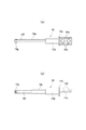
図1(a)、(b)は、本発明に係る2軸ヒンジを用いた電子機器の1例としてのノートパソコン1を示す。このノートパソコン1は、キーボード部2aを設けた第1筐体2と、ディスプレイ部3aを設けた第2筐体3の各後部の左右個所を、本発明に係る一対の2軸ヒンジ4と6で相対的に360°に渡って開閉可能に連結させて成るもので、第2筐体3に設けたディスプレイ部3aは、手指によるタッチ操作可能な機能を有するタブレット型である。また、第1筐体2と第2筐体3には、その後部にそれぞれ2軸ヒンジ4と6を収容させる取付凹部2b、2bと3b、3bが設けられている。
FIGS. 1A and 1B show a
2軸ヒンジ4と6の構成は、左右対称である点を除けば、両者共に同じ構成であるので、以下、その一方の指示記号4のもののみを説明し、他方の指示記号6で示したものの説明は省略する。勿論、動作に支障がない場合には、指示記号6で示した2軸ヒンジの構成を別なものとしてもよい。
The configurations of the biaxial hinges 4 and 6 are the same except that they are symmetrical. Therefore, only one of the
また、以下に説明する2軸ヒンジ4の2軸ヒンジ部4aや操作手段の1例である沈込み手段40、さらには作動機構50は図示したものに限定されない。
Further, the
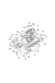
図2〜図17は、本発明に係る2軸ヒンジ4の一実施例を示す。本発明に係る2軸ヒンジ4は、2軸ヒンジ部4aと作動機構50とから成る。まず、この2軸ヒンジ4の2軸ヒンジ部4aの部分から説明する。とくに図2〜図5において、指示記号10で示したものは、2軸ヒンジ部4aの第1ヒンジシャフトである。この第1ヒンジシャフト10は、とくに図5と図6(a)、(b)に示したように、その一端部側から断面扁平形状を呈し、その表面に取付孔10b、10bを設けた取付板部10aと、この取付板部10aに続いて設けられたフランジ部10cと、このフランジ部10cに続いて設けられた円形軸部10dと、この円形軸部10dに続いて設けられたところその両側を削除することにより断面略楕円形状を呈するように加工して成る当該円形軸部10dより小径の第1変形軸部10eと、この第1変形軸部10eに続いて設けられたところのその両側を削除することにより、断面略楕円形状を呈するように加工して成る第1変形軸部10eより薄い肉厚の第2変形軸部10fと、この第2変形軸部10fに続いて設けられた雄ネジ部10gとから構成されている。
2 to 17 show an embodiment of a
図2乃至図4に示したように、第1ヒンジシャフト10の取付板部10aには、第1取付プレート11が取り付けられており、この第1取付プレート11の取付板部10aへの取付方法は、第1ヒンジシャフト10の取付孔10b、10bと第1取付プレート11の取付孔11a、11aを通したフランジ付きの取付ピン11b、11bの各端部をかしめることによって取り付けられている。そして、第1取付プレート11は、とくに図2に示したように、当該第1取付プレート11に設けた取付孔11c、11c・・を介して、取付ネジ2c、2c・・を用いて第1筐体2の上面側へ取り付けられる構成である。尚、取付ピン11b、11bはナット付きの取付ネジとしてもよい。
As shown in FIGS. 2 to 4, the first mounting
次に、同じくとくに図2と図5とに図7(a)、(b)に示したように、指示記号12で示したものは、第1ヒンジシャフト10に対して上方に位置して平行に配置された第2ヒンジシャフトであり、この第2ヒンジシャフト12は、とくに図5と図7(a)、(b)に示したように、その一端部側から断面扁平形状を呈し、その表面に取付孔12b、12bを設けた取付板部12aと、この取付板部12aに続いて設けられた円形軸部12cと、この円形軸部12cに続いて設けられたところの断面略楕円形状を呈して成る第1変形軸部12dと、この第1変形軸部12dに続いて設けられた第1変形軸部12dよりもやや薄い第2変形軸部12eと、この第2変形軸部12eに続いて設けられた雄ネジ部12fとから構成されている。
Next, particularly, as shown in FIGS. 2A and 2B and FIGS. 2A and 2B and FIGS. 3A and 3B, the one indicated by the
とくに図2乃至図4に示したように、第1ヒンジシャフト10と第2ヒンジシャフト12は、所定間隔を空けて対置させたところの、後述する第1連結部材を兼ねる同期回転手段14のギアサポート部材15に設けた第1A軸受孔15c、第1B軸受孔15dと、第2連結部材を兼ねるフリクショントルク発生手段30のフリクションプレート31に設けた第2A軸受孔31a、第2B軸受孔31bと、第3連結部材を兼ねる吸込み手段35のカムプレート部材36に設けた第3A軸受孔36a、第3B軸受孔36b内を回転可能に挿通することにより、互いに平行状態で軸支されている。
In particular, as shown in FIG. 2 to FIG. 4, the
図2と図3に示したように、取付板部12aには、第2取付プレート13が取り付けられており、この第2取付プレート13の取付板部12aへの取付方法は、第2ヒンジシャフト12の取付孔12b、12bと第2取付プレート13の取付孔13a、13aを通したフランジ付きの取付ピン13b、13bの端部をかしめることによって取り付けられている。そして、第2取付プレート13は、とくに図2に示したように、当該第2取付プレート13に設けた取付孔13c、13c・・を介して、取付ネジ3c、3c・・を用いて第2筐体3の下面側へ取り付けられる構成である。尚、取付ピン13b、13bはこれをナット付きの取付ネジとしてもよい。
As shown in FIGS. 2 and 3, the second mounting
次に、2軸ヒンジ部4aの第1ヒンジシャフト10と第2ヒンジシャフト12の間に設けられた回転制御手段5について説明する。この回転制御手段5は、第1回転制御手段5aと第2回転制御手段5bから成り、第1回転制御手段5aと第2回転制御手段5bは、それぞれ同期回転手段14、弾性手段21、フリクショントルク発生手段30、及び吸込み手段35から構成されている。さらに詳しくは、第1回転制御手段5aは、同期回転手段14、第1弾性手段21a、第1フリクショントルク発生手段30a、及び第1吸込み手段35aから構成され、第2回転制御手段5bは、同期回転手段14、第2弾性手段21b、第2フリクショントルク発生手段30b、及び第2吸込み手段35bから構成されている。
Next, the rotation control means 5 provided between the
そこでまず、同期回転手段14から説明する。この同期回転手段14は、とくに図3乃至図5と及び図8に示したように、下部と上部に一側方に向けて設けた下部突出部15aと上部突出部15bにそれぞれ第1A軸受孔15cと第1B軸受孔15dを有し、この各第1A軸受孔15cと第1B軸受孔15dに、第1ヒンジシャフト10の第1変形軸部10eと第2ヒンジシャフト12の第1変形軸部12dをそれぞれ回転可能に挿通させて成る第1連結部材を兼ねるギアサポート部材15と、このギアサポート部材15の下部突出部15aの上側と上部突出部15bの下側に設けた第1軸支溝15eと第2軸支溝15fに、図5と図9に示したように軸心を共通にして設けた下部支軸20aと上部支軸20bを回転可能に挿入支持させたところのその下部と上部に下部傘歯部20cと上部傘歯部20dを有するとくに図9に示した中間ギア20と、この中間ギア20の下部傘歯部20cと噛合させ、第1ヒンジシャフト10の第1変形軸部10eに、その中心部軸方向に設けた変形挿通孔17aを挿通係合させた傘歯車から成るとくに図10に示した第1ギア17と、中間ギア20の上部傘歯部20dと噛合させ、第2ヒンジシャフト12の第1変形軸部12dにその中心部軸方向に設けた変形挿通孔18aを挿通係合させた同じく傘歯車から成るとくに図10に示した第2ギア18とで構成されている。尚、第1ギア17と第2ギア18は構成が同じであるので、図10においては、第1ギア17のみを示し、第2ギア18の指示記号は括弧書きで表示してある。また、ギアサポート部材15の略中央部に設けられた円形状の孔は、後述する作動機構50の固定カム部材51用の係止孔15gである。
Therefore, the synchronous rotation means 14 will be described first. Particularly, as shown in FIGS. 3 to 5 and FIG. 8, the synchronous
次に、2軸ヒンジ部4aの各第1ヒンジシャフト10と第2ヒンジシャフト12の各先端部側に設けられている弾性手段21について説明する。この弾性手段21は、とくに図3乃至図5に示したように、第1ヒンジシャフト10側の第1弾性手段21aと第2ヒンジシャフト12側の第2弾性手段21bから成る。同図によれば、第1弾性手段21aは、その各円形挿通孔22aに第1ヒンジシャフト10の第2変形軸部10fを挿通させつつ重ねて設けた複数の皿バネ、或いはスプリングワッシャーなどの第1弾性部材22と、この第1弾性部材22に隣接して設けたところのその変形挿通孔23aに第2変形軸部10fを挿通係合させて設けた第1押えワッシャー23と、この第1押えワッシャー23に隣接して第1ヒンジシャフト10の雄ネジ部10gにその雌ネジ孔24aをネジ着させて設けた第1締付ナット24とで構成されている。
Next, the elastic means 21 provided on the tip end sides of the
第2弾性手段21bは、とくに図3乃至図5に示したように、その各円形挿通孔25aに第2ヒンジシャフト12の第2変形軸部12eを挿通させつつ重ねて設けた複数枚の皿バネ、或いはスプリングワッシャーなどの第2弾性部材25と、この第2弾性部材25に隣接して設けたところのその変形挿通孔26aに第2変形軸部12eを挿通係合させて設けた第2押えワッシャー26と、この第2押えワッシャー26に隣接して第2ヒンジシャフト12の雄ネジ部12fに雌ネジ孔27aをネジ着させて設けた第2締付ナット27とで構成されている。
The second
この弾性手段21は、後述するように、フリクショントルク発生手段30と、吸込み手段35に圧接力を作用させ、第1筐体2と第2筐体3の開閉操作時の第1ヒンジシャフト10と第2ヒンジシャフト12の回転時に、フリクショントルク創出機能と吸込み機能を発揮させるものである。
The elastic means 21 exerts a pressing force on the friction torque generating means 30 and the suction means 35 as described later, and the
次に、フリクショントルク発生手段30について説明する。とくに図3乃至図5に示したように、このフリクショントルク発生手段30は、同期回転手段14に隣接して設けられており、下側の第1フリクショントルク発生手段30aと上側の第2フリクショントルク発生手段30bとから構成されている。このうち第1フリクショントルク発生手段30aは、とくに図3乃至図5に示したように、その下部側と上部側に第1ヒンジシャフト10の第1変形軸部10eと第2ヒンジシャフト12の第1変形軸部12dをそれぞれ回転可能に挿通させた第2A軸受孔31aと第2B軸受孔31bを有するフリクションプレート31の下部側を挟んで両側に配置され、第1ギア17とカムプレート部材36の片側下部とで挟まれて設けられたところの第1ヒンジシャフト10の第1変形軸部10eをその第1変形挿通孔32aと第2変形挿通孔32bに挿通係合させて設けた第1Aフリクションワッシャー32A及び第1Bフリクションワッシャー32Bと、上述した第1弾性手段21aとで構成されている。
Next, the friction torque generating means 30 will be described. Particularly, as shown in FIGS. 3 to 5, this friction torque generation means 30 is provided adjacent to the synchronous rotation means 14, and the lower first friction torque generation means 30a and the upper second friction torque are provided. It comprises the generating means 30b. Among them, the first friction torque generating means 30a is, as particularly shown in FIGS. 3 to 5, the first
このうち第1Aフリクションワッシャー32Aは、フリクションプレート31の下部側の一側部と同期回転手段14の第1ギア17との間に挟まれており、第1Bフリクションワッシャー32Bは、フリクションプレート31の下部側の他側部と、吸込み手段35のカムプレート部材36の下部側の一側面との間に挟まれている。そして、これらの第1Aフリクションワッシャー32Aと第1Bフリクションワッシャー32Bは、第1ヒンジシャフト10が回転すると第1ギア17と共に回転し、第1Aフリクションワッシャー32Aは、フリクションプレート31の片側との間、第1Bフリクションワッシャー32Bは、フリクションプレート31のもう一方の側と、カムプレート部材36の下側の片側との間において、フリクショントルクが創出される構成である。このようにフリクショントルクが創出される第1Aフリクションワッシャー32A及び第1Bフリクションワッシャー32Bとフリクションプレート31の各両側、及びカムプレート部材36の片側には、それぞれナナコメ加工部32c、32d・31c、31d・32e、32f・36iが設けられており、耐久性の向上が図られている。尚、第1Aフリクションワッシャー32Aが第1ギア17と接する側のナナコメ加工部32cは省略することができる。
Among them, the first
第2フリクショントルク発生手段30bは、とくに図3乃至5に示したように、その下部側と上部側に第1ヒンジシャフト10の第1変形軸部10eと第2ヒンジシャフト12の第1変形軸部12dをそれぞれ回転可能に挿通させた第2A軸受孔31aと第2B軸受孔31bを有するフリクションプレート31の上部側を挟んで両側に配置され、第2ギア18とカムプレート部材36の片側上部とで挟まれて設けられたところの第2ヒンジシャフト12の第2変形軸部12eをその第3変形挿通孔33aと第4変形挿通孔33bに挿通係合させて設けた第2Aフリクションワッシャー33A及び第2Bフリクションワッシャー33Bと、上述した第2弾性手段21bとで構成されている。このうち第2Aフリクションワッシャー33Aは、フリクションプレート31の上部側の一側部と同期回転手段14の第2ギア18との間に挟まれており、第2Bフリクションワッシャー33Bは、フリクションプレート31の上部側の他側部と、吸込み手段35のカムプレート部材36の上部側の一側面との間に挟まれている。そして、第2ヒンジシャフト12が回転すると第2ギア18と共に回転し、第2Aフリクションワッシャー33Aは、フリクションプレート31の片側との間、第2Bフリクションワッシャー33Bは、フリクションプレート31のもう一方の側と、カムプレート部材36の上部片側との間において、フリクショントルクが創出される構成である。
The second friction torque generating means 30b, as particularly shown in FIGS. 3 to 5, has a first
以上のようにフリクショントルクが創出される第2Aフリクションワッシャー33Aと第2Bフリクションワッシャー33B及びフリクションプレート31の各両側、及びカムプレート部材36の上部一方の側には、とくに図5と図11と図12に示したように、それぞれナナコメ加工部33c、33d・31e、31f・33e、33f・36jが設けられており、耐久性の向上が図られている。尚、第2Aフリクションワッシャー33Aが第2ギア18と接する側のナナコメ加工部33cは省略することができる。
As shown above, on both sides of the second
次に、フリクショントルク発生手段30に隣接して弾性手段21との間に吸込み手段35が設けられている。この吸込み手段35は、下側の第1ヒンジシャフト10側の第1吸込み手段35aと、上側の第2ヒンジシャフト12側の第2吸込み手段35bとから成る。まず、第1吸込み手段35aは、とくに図13に示したように、第3連結部材を兼ねるカムプレート部材36の下部側の第3A軸受孔36a側の一側部側に設けた略円弧状の第1Aカム凹部36c及び第1Bカム凹部36dと、その変形挿通孔37aへ第1ヒンジシャフト10の第1変形軸部10eを挿通係合させることによって拘束されると共に、その側面の外側に対向させて設けた大小の第1Aカム凸部37b及び第1Bカム凸部37cを、第1Aカム凹部36c及び第1Bカム凹部36dと対向させて設けた第1カムフォロワー37と、この第1カムフォロワー37に接して当該第1カムフォロワー37をカムプレート部材36に圧接させる第1弾性手段21aとで構成されている。尚、このカムプレート部材36の一側面側には突起36gが設けられ、この突起36gにはヒンジケース取付用の雌ネジ部36hが設けられている。
Next, suction means 35 is provided adjacent to the friction torque generation means 30 and between the
第2吸込み手段35bは、とくに図13に示したように、第3連結部材を兼ねるカムプレート部材36の上部側の第3B軸受孔36b側の一側部外側に設けた略円弧状の第2Aカム凹部36e及び第2Bカム凹部36fと、その変形挿通孔38aを第2ヒンジシャフト12の第1変形軸部12dを挿通係合させることによって拘束されると共に、その側面の外側に設けた大小の第2Aカム凸部38b及び第2Bカム凸部38cを、第2Aカム凹部36e及び第2Bカム凹部36fと対向させて設けた第2カムフォロワー38と、この第2カムフォロワー38に接して当該第2カムフォロワー38をカムプレート部材36に圧接させる第2弾性手段21bとで構成されている。尚、第1カムフォロワー37と第2カムフォロワー38は、それぞれ第1ヒンジシャフト10と第2ヒンジシャフト12に回転を拘束されているが、軸方向にスライド可能である。
The second suction means 35b, as particularly shown in FIG. 13, is a substantially arc-shaped second A provided on the outer side of one side of the third
また、カムプレート部材36は、とくに図5に示したように、その一側面の下部側と上部側の第3A軸受孔36aと第3B軸受孔36bの回りにナナコメ加工部36i、36jが設けられることにより、フリクショントルク発生手段30の第2のフリクションプレートを兼ねている。
Further, as shown in FIG. 5, the
尚、2軸ヒンジ部4aには、同期回転手段14から弾性手段21に至る回転制御手段5が収容されるヒンジケース7を取り付けることが推奨される。このヒンジケース7は、とくに図2と図5と図15に示したように、断面長孔形状を示した筒状のものであり、その内部にその中央部を横切って取付孔7aを設けた取付部7bが設けられている。このヒンジケース7には、同期回転手段14と、フリクショントルク発生手段30と、吸込み手段35と、弾性手段21が収容され、取付ネジ7eで取付部7bに設けた取付孔7aを介して、カムプレート部材36に設けた突起36gに設けた雌ネジ部36hに取り付けられる構成である。そして、下部収容部7c側には、同期回転手段14と、第1フリクショントルク発生手段30aと、第1吸込み手段35aと、第1弾性手段21aが収容され、上部収容部7d側には、同期回転手段14と、第2フリクショントルク発生手段30bと、第2吸込み手段35bと、第2弾性手段21bが収容される構成である。ヒンジケース8についてはその内部構造の図示を省略してあるが、図15に示したように指示記号が異なるのみで、ヒンジケース7と同じ構成である。即ち、取付孔8a、取付部8b、下部収容部8c、及び上部収容部8dを有している。
In addition, it is recommended to attach the
そして、ヒンジケース7は、とくに図2に示したように、本発明に係る2軸ヒンジ4で連結されたノートパソコン1の第1筐体2と第2筐体3を閉じた際には、当該第1筐体2と第2筐体3に設けた取付凹部2bと3b内に収容されている。
And, as shown in FIG. 2, especially when the
次に、操作手段の1例であるキーボード部2aの沈込み手段40の構成について説明する。この沈込み手段40は、図19と図21に示したように、第1筐体2上に設けたキーボード部収容部41内に設けたベースプレート42と、このベースプレート42上に所定間隔を空けて設けられたところのキーボード部2aを保持するキーボード部保持プレート46と、ベースプレート42とキーボード部保持プレート46との間に設けたカム機構43と、キーボード部2aをキーボード部収容部41内に押圧する弾性部材47とで構成されている。カム機構43は、リンク部材54に連結された連係部材58と、この連係部材に連結されベースプレート42上にスライド可能に設けられたスライド部材44と、このスライド部材44に所定間隔を空けて取り付けられ、キーボード部保持プレート46を保持する複数のカム部材45、45・・・とで構成され、各カム部材45、45・・・は傾斜部45a、45a・・・を有し、この傾斜部45a、45a・・・の上端部に平坦なキーボード部保持プレート46を載置保持するキーボード載置部45b、45b・・・を有している。キーボード載置部45b、45b・・・はさらに係止溝部45c、45c・・・を有し、キーボード部保持プレート46に設けた長孔部46a、46a・・・とそのスライド位置により、係合解離するように構成されている。尚、このカム機構43は一例であって、実施例のものに限定されない。リンク機構によってもよい。また、スライド部材44は、連係部材58を省略して、リンク部材54と直接連結されるように構成してもよい。
Next, the configuration of the sinking means 40 of the
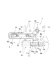
次に、沈込み手段40に対する作動機構50について説明する。この作動機構50は、実施例では、ギアサポート部材15に固定された固定カム部51aを有する固定カム部材51と、固定カム部51aと対向する側にスライドカム部52aを有し、第1取付プレート11と係合状態で前記第1ヒンジシャフト10の軸方向へスライド可能に取り付けられたスライドカム部材52と、このスライドカム部材52と第1取付プレート11との間に設けられ、スライドカム部材52を一方向へスライド付勢させる弾性部材53と、スライドカム部材52と第1取付プレート11との間に設けられ、前記スライドカム部材52の前記第1ヒンジシャフト10の軸方向へのスライド動作をこの動作と直交する方向へ変換して前記沈込み手段40へ伝達するリンク部材54と、で構成されている。
Next, the
即ち、固定カム部材51は、その一端部側に設けた固定カム部51aの軸心部軸方向に設けた挿通孔51bに第1ヒンジシャフト10の円形軸部10dを回転可能に挿通させると共に、他端部に設けた係止突起51cをギアサポート部材15に中央部に設けた係止孔15gに係合させている。スライドカム部材52は、断面U字形状を呈するように形成させた抱持部52bとこの抱持部52bの一端部側に設けたスライドカム部52aとから成り、抱持部52bの上部側抱持片52cと下部側抱持片52dとの間に第1取付プレート11を挟むと共に、スライドカム部52aの軸心部軸方向に設けた挿通孔52e内に第1ヒンジシャフト10の円形軸部10dをスライド可能に挿通させて成り、固定カム部51aとスライドカム部材52のスライドカム部52aとは互いに対向当接状態にある。
That is, the fixed
上部側抱持片52cの一端部側には取付孔52fが設けられ、この取付孔52fは下側抱持片52dに設けた取付孔52gと軸心を共通にしている。上部側抱持片52cには他端部側に小径のガイド長孔52hが設けられ、このガイド長孔52hの外側に幅広のガイド溝52iが設けられている。下部側抱持片52dには一端部側から他端部側へ収容長孔52jが設けられ、この収容長孔52jの一方の終端部からは小径のガイド長孔52kが形成されている。尚、とくに図17の(b)において、指示記号52lと52mで示したものは、第1ガイドピン55と第2ガイドピン56のフランジ部55aと56a用のガイド溝である。
A mounting
引張コイルスプリングから成る弾性部材53は、収容長孔52jの中に収容され、その一端部側53aを第1取付プレート11に第1ヒンジシャフト10と平行に設けた第1ガイド長孔11dを挿通し、その上下端部を第1ガイドピン55に係止させている。この第1ガイドピン55は、抱持部52bの上部側抱持片52cと下部側抱持片52dに設けた取付孔52f、52gに取り付けられている。また、この弾性部材53の他端部53bは、上部側抱持片52cと下部側抱持片52dに挿通させた第2ガイドピン56に係止されている。このことにより、スライドカム部材52は第1ヒンジシャフト10の軸方向へスライド付勢されている。
The
第1ガイドピン55には平面長円形状を呈したリンク部材54がその一端部側の取付孔54aへ取り付けられると共に、このリンク部材54の他端部側に設けた取付孔54bには、第1取付プレート11に設けた第1ガイド長孔11dとは直交する方向に設けた第2ガイド長孔11eに挿通係合された連結ピン57に連結されている。そして、この連結ピン57に、操作手段を構成する沈込み手段40のスライド部材44への連係部材58の一端部が回転可能に連結され、第1ヒンジシャフト10と直交する方向へスライド可能である。
A
尚、第1ガイドピン55において指示記号55aで示されたものはフランジ部であり、指示記号55bで示されたものはスペーサーリングである。また、第2ガイドピン56において指示記号56aで示されたものはフランジ部であり、指示記号56bで示されたものはワッシャーである。この第2ガイドピン56は、第1取付プレート11に設けた挿通孔11fを貫通してガイド長孔52hと52kと係合している。さらに、連結ピン57において指示記号57aで示されたものはフランジ部、指示記号57bで示されたものはスペーサーリングであり、指示記号57cで示されたものはワッシャーである。
In the
次に、上記した本発明に係る2軸ヒンジ4の動作について以下に説明する。まず、本発明に係る2軸ヒンジ部4aの部分から説明する。2軸ヒンジ部4aは、電子機器の一例であるタブレット型のノートパソコン1を構成する第1筐体2と第2筐体3を相対的に開閉させるものである。その特徴は、第1筐体2側へ第1取付プレート11を介して取り付けられる第1ヒンジシャフト10と、第2筐体3側へ第2取付プレート13を介して取り付けられる第2ヒンジシャフト12とを、それぞれ第1連結部材を兼ねる同期回転手段14のギアサポート部材15と、第2連結部材を兼ねるフリクションプレート31と、第3連結部材を兼ねるカムプレート部材36と、で平行状態に連結して互いに回転可能に設けたものである。第1筐体2と第2筐体3のどちらか一方を他方に対して開閉させると、同期回転手段14によって他方のものも同時に開かれることから、開閉操作が短時間で済みかつ容易となる。
Next, the operation of the
即ち、第1筐体2に対して第2筐体3を図1(b)に示した閉成状態から、例えば第1筐体2を片手に持って、もう一方の手で第2筐体3を時計方向へ開くと、まず、第1ヒンジシャフト10が時計方向へ回転し、同時に第1ギア17が同一方向の時計方向へ回転する。この第1ギア17が時計方向へ回転すると、この第1ギア17の第1傘歯部17bが噛み合っている中間ギア20の下部傘歯部20cを介して当該中間ギア20が回転し、この中間ギア20の上部傘歯部20dとその第2傘歯部18bを噛み合わせている第2ヒンジシャフト12に取り付けた第2ギア18が反時計方向へ回転することから、第2ヒンジシャフト12が第1ヒンジシャフト10とは反対方向へ回転することになり、第1筐体2は第2筐体3と共にその反対方向へ回転して開閉されることになり、操作性の向上を図ることができるものである。
That is, for example, from the closed state shown in FIG. 1B with respect to the
次に、吸込み手段35による吸込み動作は、第1筐体2と第2筐体3がともに360°まで開かれる際に、その少し手前から動作し、第1筐体2と第2筐体3は自動的に開かれ、その全開状態を維持することになる。この第1吸込み手段35aと第2吸込み手段35bの動作は、第1筐体2と第2筐体3が共に動作して、0°まで閉じられる時になされる。そして、この吸込み手段35によって、第1筐体2と第2筐体3の閉成状態並びに全開状態において、第1筐体2と第2筐体3の間にラッチ機構を設けなくとも、自然に第1筐体2及び第2筐体3が開いたり閉じたりしてしまうことなく閉成状態を保持できるものである。
Next, when the
さらに、この状態、つまり第1筐体2と第2筐体3が同期回転手段14を介して同期して互いに反対方向へ開かれ、合計で360°まで開かれた全開状態において、第1筐体2と第2筐体3は、その閉成状態の時とは逆の方向において互いに重なり合うことになる。
Furthermore, in this state, that is, in the fully open state in which the
以上の第1筐体2と第2筐体3の相対的開閉操作中において、フリクショントルク発生手段30の第1フリクショントルク発生手段30aと第2フリクショントルク発生手段30bは、第1ヒンジシャフト10と第2ヒンジシャフト12の相互の回転動作時にそれぞれ同時に動作する。そして、第1フリクショントルク発生手段30aは、第1Aフリクションワッシャー32A及び第1Bフリクションワッシャー32Bとで、フリクションプレート31の下部両側と第3連結部材を兼ねるカムプレート部材36の下部片側との間にフリクショントルクを発生させ、第1筐体2と第2筐体3の開閉動作時の任意の角度における安定停止作用を行うことができるものである。
During the relative opening and closing operation of the
第2フリクショントルク発生手段30bは、第2Aフリクションワッシャー33A及び第2Bフリクションワッシャー33Bとで、フリクションプレート31の上部両側と第3連結部材を兼ねるカムプレート部材36の上部片側との間にフリクショントルクを発生させ、第1筐体2と第2筐体3の開閉動作時の任意の角度における安定停止作用を行うことができるものである。
The second friction torque generating means 30b is configured by the second
さらに、吸込み手段35は、上述したように、その第1吸込み手段35aと第2吸込み手段35bが、それぞれ第1ヒンジシャフト10と第2ヒンジシャフト12が開閉角度0°と180°の時にその少し手前から動作し、第1カムフォロワー37の第1Aカム凸部37b及び第1Bカム凸部37cが、第3連結部材を兼ねるカムプレート部材36の第1Aカム凹部36c及び第1Bカム凹部36dへ落ち込み、第2カムフォロワー38の第2Aカム凸部38b及び第2Bカム凸部38cが、第3連結部材を兼ねるカムプレート部材36の第2Aカム凹部36e及び第2Bカム凹部36fに落ち込むことにより、吸込み機能を発揮し、第1筐体2と第2筐体3を自動的に開成方向及び閉成方向へ回転付勢させるものである。
Furthermore, as described above, the suction means 35 has its first suction means 35a and second suction means 35b slightly when the
そして、本願発明に係る2軸ヒンジ4は、ノートパソコン1をそれ本来の用い方で用いることができた上で、第1筐体2を第2筐体3に対して2軸ヒンジ部4aを介して互いに反対方向へ同期して開閉させて、略L字形状にしたり、山形状にしたり、重ね合わせて平板状としたりして、第2筐体3を操作者側に向けてタブレットとして種々多様な用い方をすることができるものである。
Then, the two-
次に、第1筐体2と第2筐体3が0°の閉成状態から相対的に180°づつ合計で360°まで開閉される際の、操作手段の1例であるキーボード部2aの沈込み手段40と、この沈込み手段40を動作させる作動機構50の動きについて、図面に基づいて説明する。尚、本願明細書においては、操作手段の例として、キーボード部2aの沈込み手段40のみを示したが、操作手段はこのものに限定されず。ゴム足の沈込み手段や、第1筐体と第2筐体の開閉操作に伴って動作する当該第1筐体や第2筐体に設けたその他の機構や部材に対する動作を行う操作手段も含まれるものである。本願特許請求の範囲で、キーボード部やゴム足などに対する操作手段と記載しているのはその意味であり、単なる例示に過ぎない。
Next, in the
図19と図20に示したように、第1筐体2と第2筐体3が閉じられた開閉角度0°の時には、ヒンジケース7は直立状態にあり、作動機構50のスライドカム部材52は、そのスライドカム部52aが固定カム部材51の固定カム部51aに押され、弾性部材53の弾力に抗して図中右側に移動しており、リンク部材54と沈込み手段40の連係部材58に連結されたスライド部材44は、カム機構43のカム部材45、45…を介してキーボード部2aの上部を第1筐体2の上面より突出させた状態を保っている。この状態を示したのが図19である。
As shown in FIGS. 19 and 20, when the opening and closing angle is 0 ° when the
この閉成状態から、第2筐体3を第1筐体2に対して時計方向へ開くと、或は第1筐体2を第2筐体3に対して反時計方向へ開いてもよいが、同期回転手段14を介して第1筐体2に取り付けた第1取付プレート11と共に第1ヒンジシャフト10が反時計方向へ回転する。すると、固定カム部材51の固定カム部51aに当接しているスライドカム部材52のスライドカム部52aが弾性部材53の弾力により第1ヒンジシャフト10の軸方向左側へ移動することからスライドカム部材52が第1ガイドピン55と共に同一方向へスライドする。すると、第1ガイドピン55に連結されているリンク部材54が第2ガイド長孔11eに案内されて第1ヒンジシャフト10と直交する方向にスライドすることから、リンク部材54に連結されている操作手段の一例である沈込み手段40の連係部材58がスライドして、キーボード部保持プレート46のカム部材45、45・・・を介してキーボード部2aを第1筐体2の中に沈み込ませることとなるものである。このように第1筐体2と第2筐体3が同期回転手段14を介して180°ずつ反対方向へ回転して合計で360°開かれ、互いに反対方向へ重なりあった状態を示したものが図21である。したがって、第1筐体2のキーボード部2a側が台上に置かれても、キーボード部2aの各種キーが直接接触することなく、押されて誤作動するのを防止することができるものである。
From the closed state, when the
第2筐体3に対して開いた第1筐体2を元の閉成位置まで戻していくと、或は第2筐体3を第1筐体2に対して閉成位置まで戻していくようにしてもよいが、時計方向に回転する第1取付プレート11と共にスライドカム部材52が弾性部材53の弾力に抗して、先ほどとは逆方向の右方向へスライドすることから、リンク部材54により沈込み手段40のスライド部材44が連係部材58を介して2軸ヒンジ部4a側へスライドするようになり、カム部材45、45…を介してキーボード部2aは沈み込み状態から元の突出状態へ戻ることになるものである。
When the
尚、2軸ヒンジ部4aのその他の実施例としては、図示は省略するが、第1ギア17と第2ギア18をそれぞれ平歯車にして、互いに中間ギアを介さずに直接噛み合うように構成することができる。さらに、弾性部材53は、これを圧縮コイルスプリング或は弾性を備えたゴムを始めとする合成樹脂製のものなどに代えることが可能である。また、ヒンジケース7や8は、これがなくともとくに2軸ヒンジ4や6の機能に支障は生じないが、このヒンジケース7や8があると、2軸ヒンジ4や6をノートパソコン1へ取り付けた際に、同期回転手段14、或は先行公知技術の選択的回転規制手段、フリクショントルク発生手段30、及び吸込み手段35、或は先行公知技術のストッパー手段等が外部へ露出することがないので、外観上すっきりとしたものになるという利点がある。
In addition, although illustration is abbreviate | omitted as another Example of 2
また、本発明に係る作動機構50で動作させることができるものは、キーボード部2aの沈込み手段40に限らず、第1筐体2に設けたゴム足の沈込み手段、その他の操作手段とすることができることは説明した。
The
本発明は以上のように構成したので、とくにノートパソコンのような電子機器やその他のもので、第1筐体と第2筐体を互いに同期させ、或は交互に開き、全体で360°の範囲で開閉させる場合の2軸ヒンジとして好適に用いられるものであるが、とくにノートパソコンの中で同時にタッチ機能を有するタブレット型ノートパソコンに用いて好適である。 Since the present invention is configured as described above, the first case and the second case are synchronized with each other or opened alternately, especially in an electronic device such as a notebook personal computer, or the like, and the whole 360 ° Although it is suitably used as a two-axis hinge in the case of opening and closing within a range, it is particularly suitable for use in a tablet notebook computer having a touch function at the same time in a notebook computer.
1 ノートパソコン
2 第1筐体
2a キーボード部
3 第2筐体
4 2軸ヒンジ
4a 2軸ヒンジ部
5 回転制御手段
6 2軸ヒンジ
10 第1ヒンジシャフト
11 第1取付プレート
12 第2ヒンジシャフト
13 第2取付プレート
14 同期回転手段
15 ギアサポート部材
15a 下部突出部
15b 上部突出部
17 第1ギア
18 第2ギア
20 中間ギア
20c 下部傘歯部
20d 上部傘歯部
21a 第1弾性手段
21b 第2弾性手段
30 フリクショントルク発生手段
30a 第1フリクショントルク発生手段
30b 第2フリクショントルク発生手段
31 フリクションプレート
32A 第1Aフリクションワッシャー
32B 第1Bフリクションワッシャー
33A 第2Aフリクションワッシャー
33B 第2Bフリクションワッシャー
35 吸込み手段
35a 第1吸込み手段
35b 第2吸込み手段
36 カムプレート部材
36a 第3A軸受孔
36b 第3B軸受孔
36c 第1Aカム凹部
36d 第1Bカム凹部
36e 第2Aカム凹部
36f 第2Bカム凹部
37 第1カムフォロワー
37b 第1Aカム凸部
37c 第1Bカム凸部
38 第2カムフォロワー
38b 第2Aカム凸部
38c 第2Bカム凸部
40 沈込み手段(操作手段)
43 カム機構
46 キーボード部保持プレート
50 作動機構
51 固定カム部材
51a 固定カム部
52 スライドカム部材
52a スライドカム部
53 弾性部材
54 リンク部材
DESCRIPTION OF
43
Claims (9)
Priority Applications (5)
| Application Number | Priority Date | Filing Date | Title |
|---|---|---|---|
| JP2015005431A JP6544734B2 (en) | 2015-01-14 | 2015-01-14 | 2-axis hinge and electronic device using the 2-axis hinge |
| KR1020160001590A KR101768794B1 (en) | 2015-01-14 | 2016-01-06 | Biaxial hinge and terminal device using the same |
| US14/989,601 US9540855B2 (en) | 2015-01-14 | 2016-01-06 | Biaxial hinge and electronic device using the same |
| TW105100614A TWI648480B (en) | 2015-01-14 | 2016-01-08 | Two-shaft hinge and electronic apparatus using the same |
| CN201610024731.9A CN105782228B (en) | 2015-01-14 | 2016-01-14 | Biaxial hinge and electronic device using same |
Applications Claiming Priority (1)
| Application Number | Priority Date | Filing Date | Title |
|---|---|---|---|
| JP2015005431A JP6544734B2 (en) | 2015-01-14 | 2015-01-14 | 2-axis hinge and electronic device using the 2-axis hinge |
Publications (3)
| Publication Number | Publication Date |
|---|---|
| JP2016130571A JP2016130571A (en) | 2016-07-21 |
| JP2016130571A5 JP2016130571A5 (en) | 2018-02-22 |
| JP6544734B2 true JP6544734B2 (en) | 2019-07-17 |
Family
ID=56367169
Family Applications (1)
| Application Number | Title | Priority Date | Filing Date |
|---|---|---|---|
| JP2015005431A Active JP6544734B2 (en) | 2015-01-14 | 2015-01-14 | 2-axis hinge and electronic device using the 2-axis hinge |
Country Status (5)
| Country | Link |
|---|---|
| US (1) | US9540855B2 (en) |
| JP (1) | JP6544734B2 (en) |
| KR (1) | KR101768794B1 (en) |
| CN (1) | CN105782228B (en) |
| TW (1) | TWI648480B (en) |
Families Citing this family (49)
| Publication number | Priority date | Publication date | Assignee | Title |
|---|---|---|---|---|
| US9625954B2 (en) | 2014-11-26 | 2017-04-18 | Microsoft Technology Licensing, Llc | Multi-pivot hinge |
| US10174534B2 (en) | 2015-01-27 | 2019-01-08 | Microsoft Technology Licensing, Llc | Multi-pivot hinge |
| US10162389B2 (en) | 2015-09-25 | 2018-12-25 | Microsoft Technology Licensing, Llc | Covered multi-axis hinge |
| US10227808B2 (en) | 2015-11-20 | 2019-03-12 | Microsoft Technology Licensing, Llc | Hinged device |
| US9857833B2 (en) * | 2016-03-03 | 2018-01-02 | Dell Products L.P. | Information handling system low profile hinge |
| JP2018010422A (en) * | 2016-07-12 | 2018-01-18 | レノボ・シンガポール・プライベート・リミテッド | Electronic device |
| US10754391B2 (en) * | 2016-08-08 | 2020-08-25 | Microsoft Technology Licensing, Llc | Axial cam hinge |
| TWM536198U (en) * | 2016-08-24 | 2017-02-01 | First Dome Corp | Dual-axis transmission device and transmission module |
| JP6838721B2 (en) * | 2016-09-01 | 2021-03-03 | 株式会社ナチュラレーザ・ワン | Multi-axis hinges and electronic devices using this multi-axis hinge |
| US10474203B2 (en) | 2016-09-01 | 2019-11-12 | Microsoft Technology Licensing, Llc | Hinged device |
| US10364598B2 (en) | 2016-09-02 | 2019-07-30 | Microsoft Technology Licensing, Llc | Hinged device |
| US10437293B2 (en) | 2016-09-23 | 2019-10-08 | Microsoft Technology Licensing, Llc | Multi-axis hinge |
| US9927845B1 (en) * | 2016-11-04 | 2018-03-27 | Lenovo (Singapore) Pte. Ltd. | Hinge assembly |
| US10641318B2 (en) | 2016-12-09 | 2020-05-05 | Microsoft Technology Licensing, Llc | Hinged device |
| US10241548B2 (en) | 2016-12-09 | 2019-03-26 | Microsoft Technology Licensing, Llc | Computing device employing a self-spacing hinge assembly |
| CN106781383B (en) * | 2016-12-20 | 2023-09-15 | 深圳市道通智能航空技术股份有限公司 | Remote control device for unmanned aerial vehicle |
| JP6643723B2 (en) * | 2017-01-05 | 2020-02-12 | 富士通クライアントコンピューティング株式会社 | Information processing terminal and hinge unit |
| US10253804B2 (en) | 2017-01-24 | 2019-04-09 | Microsoft Technology Licensing, Llc | Hinged device |
| CN106873718B (en) * | 2017-02-24 | 2020-07-24 | 联想(北京)有限公司 | Rotating shaft structure and electronic equipment |
| KR101843759B1 (en) * | 2017-03-08 | 2018-04-02 | 주식회사 다이아벨 | Bending Hinge Apparatus and Electronic Device having it |
| CN106884861B (en) * | 2017-03-13 | 2020-04-10 | 联想(北京)有限公司 | Rotating shaft structure |
| CN107061479B (en) * | 2017-03-16 | 2020-02-21 | 联想(北京)有限公司 | Rotating shaft structure and electronic equipment |
| CN206918043U (en) * | 2017-04-19 | 2018-01-23 | 广东欧珀移动通信有限公司 | Rotating assembly and collapsible terminal |
| US10228732B2 (en) | 2017-05-19 | 2019-03-12 | Microsoft Technology Licensing, Llc | Hinge with variable sliding friction |
| USD872077S1 (en) | 2017-05-23 | 2020-01-07 | Microsoft Corporation | Electronic tablet |
| USD855056S1 (en) * | 2017-05-23 | 2019-07-30 | Microsoft Corporation | Hinge for an electronic tablet |
| USD873817S1 (en) | 2017-05-23 | 2020-01-28 | Microsoft Corporation | Electronic tablet |
| US10296044B2 (en) | 2017-06-08 | 2019-05-21 | Microsoft Technology Licensing, Llc | Hinged device |
| US10344510B2 (en) | 2017-06-16 | 2019-07-09 | Microsoft Technology Licensing, Llc | Hinged device |
| GB201718897D0 (en) | 2017-11-15 | 2017-12-27 | Microsoft Technology Licensing Llc | Superconductor-semiconductor fabrication |
| US10545540B2 (en) | 2017-07-06 | 2020-01-28 | Microsoft Technology Licensing, Llc | Systems and methods of longitudinal torsional resistance in a hinge |
| WO2019045709A1 (en) * | 2017-08-31 | 2019-03-07 | Hewlett-Packard Development Company, L.P. | Hinge assembly with vertical torque engine |
| WO2019200549A1 (en) * | 2018-04-17 | 2019-10-24 | 华为技术有限公司 | Opening and closing mechanism and electronic device |
| US10876337B2 (en) * | 2018-09-12 | 2020-12-29 | Compal Electronics, Inc. | Sliding hinge and electronic device having the same |
| TWI713433B (en) * | 2018-12-18 | 2020-12-11 | 仁寶電腦工業股份有限公司 | Expansion hinge and electronic deivce having the same |
| US11024792B2 (en) | 2019-01-25 | 2021-06-01 | Microsoft Technology Licensing, Llc | Fabrication methods |
| JP6719608B1 (en) * | 2019-02-18 | 2020-07-08 | レノボ・シンガポール・プライベート・リミテッド | Electronics |
| TWI710309B (en) * | 2019-03-25 | 2020-11-11 | 兆利科技工業股份有限公司 | A hinge module for the foldable type device |
| CN112814992B (en) * | 2019-11-18 | 2022-04-26 | 昆山纬绩资通有限公司 | Double-shaft pivot mechanism and electronic device comprising same |
| TWI712355B (en) * | 2019-12-03 | 2020-12-01 | 和碩聯合科技股份有限公司 | Multi machinie body device |
| JP6837586B1 (en) * | 2020-01-29 | 2021-03-03 | レノボ・シンガポール・プライベート・リミテッド | Portable information equipment |
| JP2023534595A (en) * | 2020-05-26 | 2023-08-10 | パーツテック コンストラクション カンパニー リミテッド | Foldable hinge module for mobile terminals |
| KR102260987B1 (en) * | 2020-07-03 | 2021-06-04 | 주식회사 서진시스템 | electronic devices having movable block and 2-axial hinge structure |
| JP6905630B1 (en) * | 2020-08-24 | 2021-07-21 | レノボ・シンガポール・プライベート・リミテッド | Hinge devices and electronic devices |
| CN114542582A (en) * | 2020-11-25 | 2022-05-27 | 北京小米移动软件有限公司 | Rotating shaft structure and folding electronic equipment |
| KR102257326B1 (en) * | 2020-12-03 | 2021-05-31 | 주식회사 파츠텍 | Foldable hinge module for mobile terminal and notebook using the same |
| KR102394122B1 (en) * | 2021-01-08 | 2022-05-13 | 주식회사 서진시스템 | electronic devices having 2-axial hinge structure |
| CN116066665A (en) * | 2021-10-29 | 2023-05-05 | 北京小米移动软件有限公司 | Hinge device and folding electronic equipment |
| TWI783789B (en) * | 2021-11-23 | 2022-11-11 | 富世達股份有限公司 | Front and rear sliding hinges |
Family Cites Families (27)
| Publication number | Priority date | Publication date | Assignee | Title |
|---|---|---|---|---|
| US6253419B1 (en) * | 2000-01-13 | 2001-07-03 | Lu Sheng-Nan | Pivot device with multiple pivotal bars for a notebook computer |
| JP2002334626A (en) * | 2001-03-07 | 2002-11-22 | Sharp Corp | Key-sliding mechanism and information equipment device equipped with key-sliding mechanism |
| US6556430B2 (en) * | 2001-03-07 | 2003-04-29 | Compal Electronics, Inc. | Portable electronic device with a concealable keyboard module |
| JP2004227420A (en) * | 2003-01-24 | 2004-08-12 | Sharp Corp | Information processor |
| JP2005023955A (en) * | 2003-06-30 | 2005-01-27 | Casio Comput Co Ltd | Hinge structure, image pickup device and cellular phone device |
| JP5114136B2 (en) | 2007-09-05 | 2013-01-09 | 株式会社 サンコー | Tilt hinge device |
| JP5333054B2 (en) * | 2009-08-26 | 2013-11-06 | ソニー株式会社 | Electronics |
| CN201639612U (en) * | 2009-12-16 | 2010-11-17 | 深圳市爱斯讯科技有限公司 | Keyboard lifting system and slider phone with same |
| US20110265288A1 (en) * | 2010-04-29 | 2011-11-03 | Yung-Chang Chiang | Two-stage dual-pintle hinge |
| CN201874977U (en) * | 2010-08-18 | 2011-06-22 | 鸿富锦精密工业(深圳)有限公司 | Hinge structure |
| CN102619866A (en) * | 2011-01-28 | 2012-08-01 | 鸿富锦精密工业(深圳)有限公司 | Hinge structure |
| US8451595B2 (en) * | 2011-02-25 | 2013-05-28 | Research In Motion Limited | Mobile device with a concealed keyboard |
| TWM422001U (en) * | 2011-07-13 | 2012-02-01 | Quanta Comp Inc | Dual-axis hinge structure and electric device having the same |
| US9201464B2 (en) | 2011-11-28 | 2015-12-01 | Lenovo (Beijing) Co., Ltd. | Terminal apparatus |
| US8687354B2 (en) * | 2012-01-30 | 2014-04-01 | Lenovo (Singapore) Pte. Ltd. | Dual shaft hinge with angle timing shaft mechanism |
| TWM430142U (en) * | 2012-02-04 | 2012-05-21 | Sinher Technology Inc | Stable opening and closing two-axis hinge |
| JP5704613B2 (en) * | 2012-05-30 | 2015-04-22 | 株式会社ナチュラレーザ・ワン | 2-axis hinge |
| TWM464981U (en) * | 2013-03-05 | 2013-11-01 | Jarllytec Co Ltd | Pin locking type biaxial hinge |
| CN203224815U (en) * | 2013-03-08 | 2013-10-02 | 赵亮 | Electronic equipment with hidden keyboard |
| CN203594683U (en) * | 2013-10-22 | 2014-05-14 | 元镫金属股份有限公司 | Trigger rotating shaft |
| JP6338176B2 (en) | 2014-02-07 | 2018-06-06 | 株式会社ナチュラレーザ・ワン | Biaxial hinge and terminal device using the biaxial hinge |
| JP6338177B2 (en) | 2014-02-20 | 2018-06-06 | 株式会社ナチュラレーザ・ワン | Biaxial hinge and terminal device using the biaxial hinge |
| JP6355233B2 (en) | 2014-03-13 | 2018-07-11 | 株式会社ナチュラレーザ・ワン | Biaxial hinge and terminal device using the biaxial hinge |
| JP6388301B2 (en) | 2014-04-10 | 2018-09-12 | 株式会社ナチュラレーザ・ワン | Hinge device and information terminal |
| CN203847552U (en) * | 2014-05-07 | 2014-09-24 | 兆利科技工业股份有限公司 | Synchronously rotating spindle device |
| TWM491325U (en) * | 2014-08-13 | 2014-12-01 | First Dome Corp | Transmission apparatus for hinge |
| CN204437047U (en) * | 2014-12-23 | 2015-07-01 | 兆利科技工业股份有限公司 | The hinge of tool transmission agency |
-
2015
- 2015-01-14 JP JP2015005431A patent/JP6544734B2/en active Active
-
2016
- 2016-01-06 US US14/989,601 patent/US9540855B2/en active Active
- 2016-01-06 KR KR1020160001590A patent/KR101768794B1/en active IP Right Grant
- 2016-01-08 TW TW105100614A patent/TWI648480B/en active
- 2016-01-14 CN CN201610024731.9A patent/CN105782228B/en active Active
Also Published As
| Publication number | Publication date |
|---|---|
| KR101768794B1 (en) | 2017-08-17 |
| US20160201367A1 (en) | 2016-07-14 |
| JP2016130571A (en) | 2016-07-21 |
| KR20160087754A (en) | 2016-07-22 |
| US9540855B2 (en) | 2017-01-10 |
| TW201625853A (en) | 2016-07-16 |
| CN105782228A (en) | 2016-07-20 |
| CN105782228B (en) | 2021-01-05 |
| TWI648480B (en) | 2019-01-21 |
Similar Documents
| Publication | Publication Date | Title |
|---|---|---|
| JP6544734B2 (en) | 2-axis hinge and electronic device using the 2-axis hinge | |
| JP6590135B2 (en) | Biaxial hinge and electronic device using the biaxial hinge | |
| JP6890829B2 (en) | Parallel 2-axis hinges and electronic devices | |
| TWI518479B (en) | Dual-axle hinge | |
| JP6324833B2 (en) | Biaxial hinge and terminal device using the biaxial hinge | |
| TWI516196B (en) | Two-shaft hinge and terminal apparatus using the same | |
| JP2019035474A5 (en) | ||
| TWI526147B (en) | Two-shaft hinge and terminal apparatus using the same | |
| JP6397195B2 (en) | Biaxial hinge device | |
| TWI588374B (en) | Two-shaft hinge and terminal apparatus using the same | |
| TW201813486A (en) | Multiaxial hinge and electronic device using the same | |
| TWI609619B (en) | Two-shaft hinge and terminal apparatus using the same | |
| KR20120112041A (en) | Hinge device, apparatus for opening or closing and portable apparatus | |
| TWI595165B (en) | Hinge device and information terminal apparatus | |
| JP2011112150A (en) | Hinge device and portable type information equipment using the same | |
| TW202350048A (en) | Hinge comprising a base, a sliding seat, a rotating shaft member, and a linkage unit to meet the synchronous sliding special design requirements of electronic products in rotation |
Legal Events
| Date | Code | Title | Description |
|---|---|---|---|
| A521 | Request for written amendment filed |
Free format text: JAPANESE INTERMEDIATE CODE: A523 Effective date: 20180111 |
|
| A621 | Written request for application examination |
Free format text: JAPANESE INTERMEDIATE CODE: A621 Effective date: 20180111 |
|
| A977 | Report on retrieval |
Free format text: JAPANESE INTERMEDIATE CODE: A971007 Effective date: 20181024 |
|
| A131 | Notification of reasons for refusal |
Free format text: JAPANESE INTERMEDIATE CODE: A131 Effective date: 20181106 |
|
| A521 | Request for written amendment filed |
Free format text: JAPANESE INTERMEDIATE CODE: A523 Effective date: 20190107 |
|
| TRDD | Decision of grant or rejection written | ||
| A01 | Written decision to grant a patent or to grant a registration (utility model) |
Free format text: JAPANESE INTERMEDIATE CODE: A01 Effective date: 20190514 |
|
| A61 | First payment of annual fees (during grant procedure) |
Free format text: JAPANESE INTERMEDIATE CODE: A61 Effective date: 20190611 |
|
| R150 | Certificate of patent or registration of utility model |
Ref document number: 6544734 Country of ref document: JP Free format text: JAPANESE INTERMEDIATE CODE: R150 |
|
| R250 | Receipt of annual fees |
Free format text: JAPANESE INTERMEDIATE CODE: R250 |
|
| R250 | Receipt of annual fees |
Free format text: JAPANESE INTERMEDIATE CODE: R250 |