US10174534B2 - Multi-pivot hinge - Google Patents
Multi-pivot hinge Download PDFInfo
- Publication number
- US10174534B2 US10174534B2 US14/606,979 US201514606979A US10174534B2 US 10174534 B2 US10174534 B2 US 10174534B2 US 201514606979 A US201514606979 A US 201514606979A US 10174534 B2 US10174534 B2 US 10174534B2
- Authority
- US
- United States
- Prior art keywords
- individual
- links
- cammed
- computing device
- rotation
- Prior art date
- Legal status (The legal status is an assumption and is not a legal conclusion. Google has not performed a legal analysis and makes no representation as to the accuracy of the status listed.)
- Active
Links
Images


Classifications
-
- E—FIXED CONSTRUCTIONS
- E05—LOCKS; KEYS; WINDOW OR DOOR FITTINGS; SAFES
- E05D—HINGES OR SUSPENSION DEVICES FOR DOORS, WINDOWS OR WINGS
- E05D3/00—Hinges with pins
- E05D3/06—Hinges with pins with two or more pins
- E05D3/14—Hinges with pins with two or more pins with four parallel pins and two arms
-
- E—FIXED CONSTRUCTIONS
- E05—LOCKS; KEYS; WINDOW OR DOOR FITTINGS; SAFES
- E05D—HINGES OR SUSPENSION DEVICES FOR DOORS, WINDOWS OR WINGS
- E05D7/00—Hinges or pivots of special construction
-
- G—PHYSICS
- G06—COMPUTING; CALCULATING OR COUNTING
- G06F—ELECTRIC DIGITAL DATA PROCESSING
- G06F1/00—Details not covered by groups G06F3/00 - G06F13/00 and G06F21/00
- G06F1/16—Constructional details or arrangements
- G06F1/1613—Constructional details or arrangements for portable computers
- G06F1/1615—Constructional details or arrangements for portable computers with several enclosures having relative motions, each enclosure supporting at least one I/O or computing function
- G06F1/1616—Constructional details or arrangements for portable computers with several enclosures having relative motions, each enclosure supporting at least one I/O or computing function with folding flat displays, e.g. laptop computers or notebooks having a clamshell configuration, with body parts pivoting to an open position around an axis parallel to the plane they define in closed position
-
- G—PHYSICS
- G06—COMPUTING; CALCULATING OR COUNTING
- G06F—ELECTRIC DIGITAL DATA PROCESSING
- G06F1/00—Details not covered by groups G06F3/00 - G06F13/00 and G06F21/00
- G06F1/16—Constructional details or arrangements
- G06F1/1613—Constructional details or arrangements for portable computers
- G06F1/1633—Constructional details or arrangements of portable computers not specific to the type of enclosures covered by groups G06F1/1615 - G06F1/1626
- G06F1/1675—Miscellaneous details related to the relative movement between the different enclosures or enclosure parts
- G06F1/1681—Details related solely to hinges
-
- H—ELECTRICITY
- H04—ELECTRIC COMMUNICATION TECHNIQUE
- H04M—TELEPHONIC COMMUNICATION
- H04M1/00—Substation equipment, e.g. for use by subscribers
- H04M1/02—Constructional features of telephone sets
- H04M1/0202—Portable telephone sets, e.g. cordless phones, mobile phones or bar type handsets
- H04M1/0206—Portable telephones comprising a plurality of mechanically joined movable body parts, e.g. hinged housings
- H04M1/0208—Portable telephones comprising a plurality of mechanically joined movable body parts, e.g. hinged housings characterized by the relative motions of the body parts
- H04M1/0214—Foldable telephones, i.e. with body parts pivoting to an open position around an axis parallel to the plane they define in closed position
- H04M1/0216—Foldable in one direction, i.e. using a one degree of freedom hinge
- H04M1/022—The hinge comprising two parallel pivoting axes
Definitions
- FIGS. 1-4 show perspective views of example devices that include sequential multi-pivot hinge assembly examples in accordance with some implementations of the present concepts.
- FIGS. 5-6 are perspective views of a sequential multi-pivot hinge assembly example in the deployed and storage positions respectively.
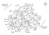
- FIGS. 7-11 are exploded perspective views of the sequential multi-pivot hinge assembly example of FIG. 5-6 .
- the present concepts relate to computing devices employing multi-pivot or multi-axis hinge assemblies to rotatably secure portions of the computing device.
- the present hinges can be thought of as sequential hinges in that the multi-pivot hinge assemblies can control a relative order in which individual hinges rotate.
- One such configuration can cause the hinges to operate in a predefined order from first to last (e.g., sequentially).
- the multi-pivot hinge assemblies can be termed ‘sequential multi-pivot hinge assemblies’.
- FIGS. 1-3 collectively show an example of a computing device 100 .
- computing device 100 has first and second portions 102 and 104 that are rotatably secured together by a sequential multi-pivot hinge assembly 106 .
- FIGS. 1-2 show the computing device in a ‘closed’ position.
- FIG. 1 shows the computing device 100 from the ‘front’ and
- FIG. 2 shows the computing device from the ‘back.’
- FIG. 3 is a partial cut-away perspective view that shows the computing device in an ‘open’ or ‘deployed’ position.
- the first and second portions can define an obtuse angle ⁇ relative to one another, as opposed to an angle close to zero in the closed position of FIGS. 1-2 .
- the deployed position can be 90 degrees or less or 180 degrees or more (e.g., a book like configuration) or up to 360 degrees.
- the deployed position may be somewhere in the range of 90 degrees to 180 degrees that is a comfortable viewing angle for the user.
- the sequential multi-pivot hinge assembly 106 can include one or more hinge stacks 302 . Aspects of the sequential multi-pivot hinge assembly 106 are described in more detail below relative to FIGS. 5-10 .
- the sequential multi-pivot hinge assembly includes rigid articulating hinge covers 304 that can obscure and/or protect the underlying elements, including the hinge stacks 302 .
- Other implementations do not include the rigid articulating covers.
- Still other implementations can include a flexible hinge cover that extends between the first portion 102 and the second portion 104 over the sequential multi-pivot hinge assembly 106 .
- computing device 100 can also include an input element or device 308 .
- the input device 308 is manifest as a keyboard 310 .
- the computing device can also include a display screen 312 , such as a touch sensitive display screen.
- the computing device can also include a processor 314 , memory/storage 316 , a battery 318 , and/or a video or graphics processor 320 , among other components/elements. These elements can be positioned in the first portion 102 and/or second portion 104 .
- the second portion 104 can be configured to be positioned on a generally horizontal surface (not specifically designated), such as a table top.
- a generally horizontal surface not specifically designated
- the first and second portions are generally parallel to one another and the horizontal surface (e.g., the first portion is juxtaposed over the second portion).
- the first portion is rotated away from the second portion, in this case to an obtuse angle.
- the sequential multi-pivot hinge assembly 106 can provide a footprint f c that is compact and easy to carry.
- the progressive or sequential nature of the sequential multi-pivot hinge assembly 106 can increase or expand the footprint of the computing device when the device is transitioned from the closed or storage position of FIGS. 1-2 to the open or deployed position of FIG. 3 .
- the closed footprint f c compares the closed footprint f c to the deployed or expanded footprint f d of FIG. 3 .
- This extended footprint feature can be especially valuable in this implementation where some or all of the electronic components, such as the display 312 , processor 314 , memory/storage 316 , and battery 318 are positioned in the first portion 102 .
- the extended footprint provided by the sequential multi-pivot hinge assembly 106 can increase stability of the computing device 100 and reduce the likelihood of the device tipping over backward in the deployed position from the weight of these components. Stated another way, the sequential nature of the sequential multi-pivot hinge assembly 106 can create a foot 322 in the deployed position that can help stabilize the computing device 100 and decrease tipping (e.g., maintain the center of mass over the footprint).
- the sequential multi-pivot hinge assembly 106 can be secured to the first and second portions 102 and 104 in a relatively permanent manner (e.g., in a manner that is not intended to be readily separable by an end use consumer).
- the sequential multi-pivot hinge assembly 106 can be secured to the first and second portions 102 and 104 in a relatively quickly attachable/detachable manner (e.g., in a manner that is intended to be readily separable by the end use consumer).
- FIG. 4 One such example of this latter configuration is shown in FIG. 4 .
- FIG. 4 shows another computing device 100 A in a view that is similar to the view of FIG. 3 .
- the sequential multi-pivot hinge assembly 106 A is configured to allow an end use consumer to easily detach either or both of the first and second portions 102 and 104 from the sequential multi-pivot hinge assembly 106 A as indicated by arrow 402 .
- the sequential multi-pivot hinge assembly 106 A can include a quick attach/detach assembly 404 .
- the quick attach/detach assembly 404 may include cooperatively operating elements 406 and 408 located on the first portion 102 and the sequential multi-pivot hinge assembly 106 A. Elements 406 and 408 can function to couple the first portion 102 to the sequential multi-pivot hinge assembly 106 A. Similar elements can function to couple the second portion 104 to the sequential multi-pivot hinge assembly 106 A.
- element 406 can be manifest as a mechanical latch and element 408 can be manifest as a receiver.
- the latch can engage the receiver to removeably couple the first portion 102 with the sequential multi-pivot hinge assembly 106 A.
- the elements 406 and 408 may magnetically couple to one another in a manner that can be overcome by the user to separate the first portion from the sequential multi-pivot hinge assembly 106 A.
- Other quick attach/detach assemblies 404 are contemplated.
- the sequential multi-pivot hinge assembly 106 A may detachably connect with either or both of the first and/or second portions. Alternatively or additionally to mechanical coupling, the quick attach/detach assembly 404 can detachably electrically couple electronic components of the first and second portions.
- the quick attach/detach assembly 404 may electrically couple/decouple processor 314 , storage/memory 316 , and/or battery 318 from the first portion 102 to the graphics processor 320 and/or keyboard 310 in the second portion 104 .
- first portion 102 may be operated as a stand-alone tablet device, and then may be attached to second portion 104 via sequential multi-pivot hinge assembly 106 A to form a device more akin to a laptop device.
- a user may also be able to exchange first portion 102 or second portion 104 for application-specific devices.
- an individual second portion may include a keyboard and/or a touchscreen.
- the user may attach a first touchscreen as the first portion and a second touchscreen as the second portion, and utilize the device like a book.
- a user may attach a touchscreen as the first portion and an input device, manifest as a keyboard and trackpad, as the second portion, and utilize the device like a laptop.
- Other configurations and implementations are contemplated.
- FIGS. 5-11 illustrate more details about the example sequential multi-pivot hinge assembly 106 including an example hinge stack 302 introduced above relative to FIG. 3 . Note that due to space constraints on the drawing pages, not all elements are labeled in each FIG. and not every instance of every element is labeled, rather representative elements are labeled.
- FIG. 5 shows the sequential multi-pivot hinge assembly 106 in an open or deployed position similar to FIG. 3 .
- FIG. 6 shows sequential multi-pivot hinge assembly 106 in a closed or storage position similar to FIG. 1 .
- FIGS. 7-10 show exploded views of sequential multi-pivot hinge assembly 106 in a sequence from open in FIG. 7 , partially closed in FIG. 8 , further closed in FIG. 9 , and fully closed in FIG. 10 .
- the example hinge stack 302 can include a first portion element (e.g., interface) 502 for securing the hinge stack 302 to the first portion 102 ( FIG. 1 ) and a second portion element (e.g., interface) 504 for securing the hinge stack 302 to the second portion 104 ( FIG. 1 ).
- Hinge stack 302 can also include rotation control elements, such as rotation limiters 506 , shafts 508 , and cammed links 510 .
- the hinge stack 302 can include an opening order-controlling set 512 ( FIG. 7 ) and a separate closing order-controlling set 514 ( FIG. 7 ).
- opening order-controlling set 512 can include links 510 ( 1 )- 510 ( 5 ) while closing order-controlling set 514 can include links 510 ( 6 )- 510 ( 10 ).
- the opening order-controlling set 512 can be further organized into first and second subsets 516 and 518 .
- the first subset 516 can include links 510 ( 1 )- 510 ( 3 ) and the second subset 518 can include links 510 ( 4 )- 510 ( 5 ).
- the closing order-controlling set 514 can be further organized into first and second subsets 520 and 522 .
- the first subset 520 can include links 510 ( 6 )- 510 ( 8 ) and the second subset 522 can include links 510 ( 9 )- 510 ( 10 ).
- links can be arranged in an end-to-end manner. This facet allows interaction between adjacent links of an individual subset as will be described below.
- Links 510 can include first and second portions 524 and 526 ( FIG. 7 ). Relative to an individual link, an individual first portion 524 can define a first passageway 528 and second portion 526 can define a second passageway 530 . Individual links can also include a cam tab (e.g., tab) 532 and a cam tab engagement surface (e.g., engagement surface) 534 . In the illustrated configuration, the links 510 can be thought of as approximating a figure-eight shape with the tab 532 on the first portion 524 and the engagement surface 534 on the second portion 526 .
- a cam tab e.g., tab
- engagement surface e.g., engagement surface
- the links 510 of the opening order-controlling set 512 can be different from the links of the closing order-controlling set 514 .
- the engagement surface 534 is generally opposite (e.g. about 180 degrees) from the tab 532 .
- the tab 532 is offset from the engagement surface (e.g., a line passing through the center of the first and second passageways 528 and 530 does not pass through a center of the tab 532 and/or the engagement surface 534 ).
- links of the first subset 516 can be offset one hinge axis from links of the second subset 518 so that an individual shaft 508 passes through first passageway 528 of an individual link in the first subset and second passageway 530 of an individual link in the second subset.
- shaft 508 ( 4 ) passes through first passageway 528 of link 510 ( 3 ) from the first subset 516 and second passageway 530 of link 510 ( 5 ) of the second subset 518 .
- links can be offset by one hinge axis relative to the first subset and the second subset.
- the shafts 508 do not have a circular profile when viewed transverse their long axis (e.g., when viewed along the xz reference plane). Instead, in this case, the shafts have a profile that approximates a capital “D”.
- the links' first passageway 528 and second passageway 830 both have a circular profile so that the shaft can turn freely within the passageways.
- the rotation limiters 506 can include a first portion 536 and a second portion 538 ( FIG. 7 , relative to rotation limiter 506 ( 4 )).
- the first portion 536 can define a first passageway 540 and the second portion 538 can define a second passageway 542 ( FIG. 7 , relative to rotation limiter 506 ( 4 )).
- the rotation limiters' first passageway 540 can have a D shaped profile (e.g., the shape of the shaft is keyed into a fixed orientation with the first portion 536 ). This configuration can allow the second portion to rotate around the keyed shaft while preventing the first portion from rotating around the keyed shaft.
- first portion 536 and the second portion 538 can define the angle of rotation b around an individual shaft (e.g., hinge axis, pivot axis, or axis of rotation) (see FIG. 7 ).
- the closing order-controlling set 514 can control the order of rotation around individual shafts 508 .
- the user can apply a closing force f c on the first portion element 502 .
- the closing force can cause counter-clockwise rotation around shaft 508 ( 1 ).
- This movement turns tab 532 of link 510 ( 6 ) away from engagement surface 534 of link 510 ( 7 ) (compare FIG. 7 to FIG. 8 ).
- Rotation can continue through a range of degrees of rotation (e.g., angle b) as defined by the rotation limiter 506 ( 1 ) associated with shaft 508 ( 1 ).
- rotation around shaft 508 ( 2 ) has already been completed and rotation around shaft 508 ( 3 ) is possible because cam tab 532 of link 510 ( 9 ) has disengaged from engagement surface 534 of link 510 ( 10 ).
- Rotation around shaft 508 ( 4 ) is still not possible because of interaction between link 510 ( 7 ) and link 510 ( 8 ).
- rotation around shaft 508 ( 4 ) can commence as rotation around shaft 508 ( 3 ) is already complete thereby disengaging the cam tab (not specifically designated) of link 510 ( 7 ) from link 510 ( 8 ).
- FIG. 11 is an intermediate position similar to FIG. 9 but with the opening order-controlling set 512 in the foreground rather than the closing order-controlling set 514 of FIG. 9 .
- rotation can commence around shaft 508 ( 3 ).
- Rotation around shaft 508 ( 3 ) clears cam tab 532 of link 501 ( 5 ) from engagement surface 534 of link 510 ( 4 ) and allows rotation around shaft 508 ( 3 ).
- rotation around shaft 508 ( 2 ) is blocked by engagement between link 510 ( 5 ) and link 510 ( 4 ) and rotation around shaft 508 ( 1 ) is blocked by engagement of link 510 ( 2 ) with link 510 ( 1 ).
- the rotation process can be repeated sequentially along the individual shafts 508 .
- the links can rotate with respect to one another. If they do not share a common axis of rotation and their cam tab and engagement surface are engaged, then the links are locked with respect to each other as rotation would cause the tab in one link to crash into the engagement surface of the other link.
- One example is manifest as a first portion and a second portion.
- This example also includes a sequential multi-pivot hinge assembly rotatably securing the first portion and the second portion from a storage position where the first portion is juxtaposed over the second portion to a deployed position where the first portion is oriented at an obtuse angle relative to the first portion.
- the sequential multi-pivot hinge assembly can include a first set of cammed links to control an order of rotation around individual hinge axes when the first portion and second portion are being rotated from the storage position to the deployed position and a separate second set of cammed links to control the order of rotation from the deployed position to the storage position.
- first set of cammed links comprises a first subset of links that are arranged end-to end with one another and a second subset of links that are arranged end-to-end with one another.
- the first subset of links are offset one hinge axis from the second subset of links.
- Individual links of the first set of links are arranged in an end-to-end manner so that the first region of a first individual link interacts with the second region of a second individual link.
- the individual links comprise a tab on the first region and an engagement surface on the second region, and wherein interaction of the tab of a first individual link and the engagement surface of an adjacent individual link controls rotation around an individual hinge axis passing through the individual link.
- sequential multi-pivot hinge assembly further comprises hinge shafts that define the hinge axes.
- hinge shafts have a circular profile when viewed transverse an axis of rotation or wherein the shaft is not circular.
- rotation control elements comprise a first portion that is configured to rotate around an individual hinge shaft and a second portion that is non-rotatably secured to the individual hinge shaft.
- first portion includes a touchscreen and the second portion includes a keyboard or a touchscreen.
- hinge cover comprises multiple rigid hinge covers or wherein the hinge cover comprises a flexible hinge cover that extends from the first portion to the second portion.
- the example can include a sequential multi-pivot hinge assembly rotatably securing the first portion and the second portion and including a first set of links configured to control a relative order of rotation around individual axes of rotation of the sequential multi-pivot hinge assembly when the first and second portions are being rotated away from one another and a second different set of links configured to control the relative order of rotation around the individual axes of rotation of the sequential multi-pivot hinge assembly when the first and second portions are being rotated toward one another.
- any combination of the above and/or below examples where at least some of the links are cammed links comprising a cam tab and a cam engagement surface.
- cammed links of the first set have a same geometric shape as the cammed links of the second set or wherein the cammed links of the first set have a different geometric shape as the cammed links of the second set.
- cammed links have a same geometric shape or wherein individual cammed links have different geometric shapes from one another.
- the second portion defines a footprint of the computing device when the first portion is juxtaposed over the second portion in a storage position and when the first portion is rotated away from the second portion the sequential multi-pivot hinge assembly expands the footprint.
- any combination of the above and/or below examples further including electronic components positioned in the first portion and wherein a center of mass of the computing device is located above the expanded footprint.
- Another example is manifest as a hinge having a first interface and a second interface.
- the example can include a sequential multi-pivot hinge assembly rotatably securing the first interface and the second interface and including a first set of elements to control rotation around individual axes starting proximate to the second interface when rotating the first and second interfaces apart and a second set of elements to control rotation starting proximate to the first interface when moving the first and second interfaces toward one another.
- the first interface includes an electrical connector and a mechanical latch.
Abstract
The description relates to devices, such as computing devices that have hinged portions. One example can include a first portion and a second portion. This example can also include a sequential multi-pivot hinge assembly rotatably securing the first portion and the second portion. The sequential multi-pivot hinge assembly can include a first set of links configured to control a relative order of rotation around individual axes of rotation of the sequential multi-pivot hinge assembly when the first and second portions are being rotated away from one another and a second different set of links configured to control the relative order of rotation around the individual axes of rotation of the sequential multi-pivot hinge assembly when the first and second portions are being rotated toward one another.
Description
The accompanying drawings illustrate implementations of the concepts conveyed in the present document. Features of the illustrated implementations can be more readily understood by reference to the following description taken in conjunction with the accompanying drawings. Like reference numbers in the various drawings are used wherever feasible to indicate like elements. Further, wherever practical, the left-most numeral of each reference number conveys the FIG. and associated discussion where the reference number is first introduced.
The present concepts relate to computing devices employing multi-pivot or multi-axis hinge assemblies to rotatably secure portions of the computing device. The present hinges can be thought of as sequential hinges in that the multi-pivot hinge assemblies can control a relative order in which individual hinges rotate. One such configuration can cause the hinges to operate in a predefined order from first to last (e.g., sequentially). As such, the multi-pivot hinge assemblies can be termed ‘sequential multi-pivot hinge assemblies’.
Introductory FIGS. 1-3 collectively show an example of a computing device 100. In this example, computing device 100 has first and second portions 102 and 104 that are rotatably secured together by a sequential multi-pivot hinge assembly 106. FIGS. 1-2 show the computing device in a ‘closed’ position. FIG. 1 shows the computing device 100 from the ‘front’ and FIG. 2 shows the computing device from the ‘back.’ FIG. 3 is a partial cut-away perspective view that shows the computing device in an ‘open’ or ‘deployed’ position. In this example, in the deployed position, the first and second portions can define an obtuse angle α relative to one another, as opposed to an angle close to zero in the closed position of FIGS. 1-2 . In other implementations, the deployed position can be 90 degrees or less or 180 degrees or more (e.g., a book like configuration) or up to 360 degrees. For instance, the deployed position may be somewhere in the range of 90 degrees to 180 degrees that is a comfortable viewing angle for the user.
As can be appreciated from FIG. 3 , the sequential multi-pivot hinge assembly 106 can include one or more hinge stacks 302. Aspects of the sequential multi-pivot hinge assembly 106 are described in more detail below relative to FIGS. 5-10 . In this example, the sequential multi-pivot hinge assembly includes rigid articulating hinge covers 304 that can obscure and/or protect the underlying elements, including the hinge stacks 302. Other implementations do not include the rigid articulating covers. Still other implementations can include a flexible hinge cover that extends between the first portion 102 and the second portion 104 over the sequential multi-pivot hinge assembly 106.
As evidenced in FIG. 3 , computing device 100 can also include an input element or device 308. In this case the input device 308 is manifest as a keyboard 310. Other implementations can employ other input devices. In this example, the computing device can also include a display screen 312, such as a touch sensitive display screen. The computing device can also include a processor 314, memory/storage 316, a battery 318, and/or a video or graphics processor 320, among other components/elements. These elements can be positioned in the first portion 102 and/or second portion 104.
In this case, the second portion 104 can be configured to be positioned on a generally horizontal surface (not specifically designated), such as a table top. In the closed position of FIGS. 1-2 , the first and second portions are generally parallel to one another and the horizontal surface (e.g., the first portion is juxtaposed over the second portion). In contrast, in the deployed position of FIG. 3 , the first portion is rotated away from the second portion, in this case to an obtuse angle.
Note that in the closed position of FIGS. 1-2 , the sequential multi-pivot hinge assembly 106 can provide a footprint fc that is compact and easy to carry. Note also, that in this implementation the progressive or sequential nature of the sequential multi-pivot hinge assembly 106 can increase or expand the footprint of the computing device when the device is transitioned from the closed or storage position of FIGS. 1-2 to the open or deployed position of FIG. 3 . For example, compare the closed footprint fc to the deployed or expanded footprint fd of FIG. 3 . This extended footprint feature can be especially valuable in this implementation where some or all of the electronic components, such as the display 312, processor 314, memory/storage 316, and battery 318 are positioned in the first portion 102. The extended footprint provided by the sequential multi-pivot hinge assembly 106 can increase stability of the computing device 100 and reduce the likelihood of the device tipping over backward in the deployed position from the weight of these components. Stated another way, the sequential nature of the sequential multi-pivot hinge assembly 106 can create a foot 322 in the deployed position that can help stabilize the computing device 100 and decrease tipping (e.g., maintain the center of mass over the footprint).
In the implementation shown in FIG. 3 , the sequential multi-pivot hinge assembly 106 can be secured to the first and second portions 102 and 104 in a relatively permanent manner (e.g., in a manner that is not intended to be readily separable by an end use consumer). Alternatively, the sequential multi-pivot hinge assembly 106 can be secured to the first and second portions 102 and 104 in a relatively quickly attachable/detachable manner (e.g., in a manner that is intended to be readily separable by the end use consumer). One such example of this latter configuration is shown in FIG. 4 .
In one example, element 406 can be manifest as a mechanical latch and element 408 can be manifest as a receiver. The latch can engage the receiver to removeably couple the first portion 102 with the sequential multi-pivot hinge assembly 106A. In another example, the elements 406 and 408 may magnetically couple to one another in a manner that can be overcome by the user to separate the first portion from the sequential multi-pivot hinge assembly 106A. Other quick attach/detach assemblies 404 are contemplated. The sequential multi-pivot hinge assembly 106A may detachably connect with either or both of the first and/or second portions. Alternatively or additionally to mechanical coupling, the quick attach/detach assembly 404 can detachably electrically couple electronic components of the first and second portions. For instance, the quick attach/detach assembly 404 may electrically couple/decouple processor 314, storage/memory 316, and/or battery 318 from the first portion 102 to the graphics processor 320 and/or keyboard 310 in the second portion 104.
Thus, the quick attach/detach assembly 404 can allow the user to be able to detach first portion 102 or second portion 104 to use either portion independently of the other. For example, first portion 102 may be operated as a stand-alone tablet device, and then may be attached to second portion 104 via sequential multi-pivot hinge assembly 106A to form a device more akin to a laptop device. A user may also be able to exchange first portion 102 or second portion 104 for application-specific devices. For example, an individual second portion may include a keyboard and/or a touchscreen. In certain scenarios, the user may attach a first touchscreen as the first portion and a second touchscreen as the second portion, and utilize the device like a book. In other scenarios, a user may attach a touchscreen as the first portion and an input device, manifest as a keyboard and trackpad, as the second portion, and utilize the device like a laptop. Other configurations and implementations are contemplated.
Referring collectively to FIGS. 5-10 , the example hinge stack 302 can include a first portion element (e.g., interface) 502 for securing the hinge stack 302 to the first portion 102 (FIG. 1 ) and a second portion element (e.g., interface) 504 for securing the hinge stack 302 to the second portion 104 (FIG. 1 ). Hinge stack 302 can also include rotation control elements, such as rotation limiters 506, shafts 508, and cammed links 510. The hinge stack 302 can include an opening order-controlling set 512 (FIG. 7 ) and a separate closing order-controlling set 514 (FIG. 7 ). In this implementation opening order-controlling set 512 can include links 510(1)-510(5) while closing order-controlling set 514 can include links 510(6)-510(10).
In this case, the opening order-controlling set 512 can be further organized into first and second subsets 516 and 518. The first subset 516 can include links 510(1)-510(3) and the second subset 518 can include links 510(4)-510(5). The closing order-controlling set 514 can be further organized into first and second subsets 520 and 522. The first subset 520 can include links 510(6)-510(8) and the second subset 522 can include links 510(9)-510(10). Within an individual subset, links can be arranged in an end-to-end manner. This facet allows interaction between adjacent links of an individual subset as will be described below.
Note further, that the links 510 of the opening order-controlling set 512 can be different from the links of the closing order-controlling set 514. For instance, relative to an individual link, in the illustrated closing order-controlling set 514, the engagement surface 534 is generally opposite (e.g. about 180 degrees) from the tab 532. In contrast, in the links of the opening order-controlling set 512, the tab 532 is offset from the engagement surface (e.g., a line passing through the center of the first and second passageways 528 and 530 does not pass through a center of the tab 532 and/or the engagement surface 534).
Relative to an individual link set, such as opening order-controlling set 512, links of the first subset 516 can be offset one hinge axis from links of the second subset 518 so that an individual shaft 508 passes through first passageway 528 of an individual link in the first subset and second passageway 530 of an individual link in the second subset. For instance, shaft 508(4) passes through first passageway 528 of link 510(3) from the first subset 516 and second passageway 530 of link 510(5) of the second subset 518. Stated another way, within an individual link set, links can be offset by one hinge axis relative to the first subset and the second subset.
Note that in this implementation, the shafts 508 do not have a circular profile when viewed transverse their long axis (e.g., when viewed along the xz reference plane). Instead, in this case, the shafts have a profile that approximates a capital “D”. The links' first passageway 528 and second passageway 830 both have a circular profile so that the shaft can turn freely within the passageways. In contrast, the rotation limiters 506 can include a first portion 536 and a second portion 538 (FIG. 7 , relative to rotation limiter 506(4)). The first portion 536 can define a first passageway 540 and the second portion 538 can define a second passageway 542 (FIG. 7 , relative to rotation limiter 506(4)). The rotation limiters' first passageway 540 can have a D shaped profile (e.g., the shape of the shaft is keyed into a fixed orientation with the first portion 536). This configuration can allow the second portion to rotate around the keyed shaft while preventing the first portion from rotating around the keyed shaft.
Other keyed shaft profiles can be utilized that cause the keyed shaft to be non-rotatable relative to individual passageways and rotatable relative to other individual passageways. For instance, a star shaped profile could be utilized where the first portion's passageway 540 matches the star profile and the second portion's passageway 542 is circular with a diameter defined by the outer points of the star. From a functional standpoint, the first portion 536 and the second portion 538 can define the angle of rotation b around an individual shaft (e.g., hinge axis, pivot axis, or axis of rotation) (see FIG. 7 ).
As mentioned above, the closing order-controlling set 514 can control the order of rotation around individual shafts 508. For instance, starting at the open position of FIG. 7 , the user can apply a closing force fc on the first portion element 502. The closing force can cause counter-clockwise rotation around shaft 508(1). This movement turns tab 532 of link 510(6) away from engagement surface 534 of link 510(7) (compare FIG. 7 to FIG. 8 ). Rotation can continue through a range of degrees of rotation (e.g., angle b) as defined by the rotation limiter 506(1) associated with shaft 508(1). During this initial phase rotation around the other shafts 508(2)-508(4) is collectively blocked by the inter-relationships of the tabs and engagement surfaces of the remaining links 510(7)-510(10) of the closing order controlling set 514.
Once rotation is completed around shaft 508(1) (e.g., tab 532 of link 510(6) disengages from engagement surface 534 of link 510(7), see FIG. 8 ), the closing force can begin rotation around shaft 508(2) while the first portion element 502 (and shaft 508(1)) move in the negative x direction. This counter-clockwise rotation around shaft 508(2) can rotate tab 532 of link 510(9) away from engagement surface 534 of link 510(10) (compare FIG. 7 , FIG. 8 , and FIG. 9 ). This process can be serially repeated for shaft 508(3). For instance, in relation to FIG. 8 , rotation around shaft 508(2) has already been completed and rotation around shaft 508(3) is possible because cam tab 532 of link 510(9) has disengaged from engagement surface 534 of link 510(10). Rotation around shaft 508(4) is still not possible because of interaction between link 510(7) and link 510(8). However, at the position of FIG. 9 , rotation around shaft 508(4) can commence as rotation around shaft 508(3) is already complete thereby disengaging the cam tab (not specifically designated) of link 510(7) from link 510(8).
Viewed from one perspective, in some implementations if the tab and engagement surface on two engaged links are both concentric to a given axis of rotation, then the links can rotate with respect to one another. If they do not share a common axis of rotation and their cam tab and engagement surface are engaged, then the links are locked with respect to each other as rotation would cause the tab in one link to crash into the engagement surface of the other link.
Various methods of manufacture, assembly, and use for sequential multi-pivot hinge assemblies are contemplated beyond those shown above relative to FIGS. 1-11 .
Various examples are described above. Additional examples are described below. One example is manifest as a first portion and a second portion. This example also includes a sequential multi-pivot hinge assembly rotatably securing the first portion and the second portion from a storage position where the first portion is juxtaposed over the second portion to a deployed position where the first portion is oriented at an obtuse angle relative to the first portion. The sequential multi-pivot hinge assembly can include a first set of cammed links to control an order of rotation around individual hinge axes when the first portion and second portion are being rotated from the storage position to the deployed position and a separate second set of cammed links to control the order of rotation from the deployed position to the storage position.
Any combination of the above and/or below examples where the first set of cammed links comprises a first subset of links that are arranged end-to end with one another and a second subset of links that are arranged end-to-end with one another. The first subset of links are offset one hinge axis from the second subset of links.
Any combination of the above and/or below examples where individual links have first and second regions. Individual links of the first set of links are arranged in an end-to-end manner so that the first region of a first individual link interacts with the second region of a second individual link.
Any combination of the above and/or below examples where the individual links comprise a tab on the first region and an engagement surface on the second region, and wherein interaction of the tab of a first individual link and the engagement surface of an adjacent individual link controls rotation around an individual hinge axis passing through the individual link.
Any combination of the above and/or below examples where the sequential multi-pivot hinge assembly further comprises hinge shafts that define the hinge axes.
Any combination of the above and/or below examples where the hinge shafts have a circular profile when viewed transverse an axis of rotation or wherein the shaft is not circular.
Any combination of the above and/or below examples further including rotation control elements that define an angle of rotation around an individual axis of rotation.
Any combination of the above and/or below examples where the rotation control elements comprise a first portion that is configured to rotate around an individual hinge shaft and a second portion that is non-rotatably secured to the individual hinge shaft.
Any combination of the above and/or below examples where the sequential multi-pivot hinge assembly is configured to create a larger footprint of the computing device in the deployed position than in the storage position.
Any combination of the above and/or below examples where the sequential multi-pivot hinge assembly is visible in both the storage position and the deployed position.
Any combination of the above and/or below examples where the first portion includes a touchscreen and the second portion includes a keyboard or a touchscreen.
Any combination of the above and/or below examples where the hinge cover comprises multiple rigid hinge covers or wherein the hinge cover comprises a flexible hinge cover that extends from the first portion to the second portion.
Any combination of the above and/or below examples where the deployed position is about 90 degrees to about 360 degrees from the storage position
Another example is manifest as a first portion and a second portion. The example can include a sequential multi-pivot hinge assembly rotatably securing the first portion and the second portion and including a first set of links configured to control a relative order of rotation around individual axes of rotation of the sequential multi-pivot hinge assembly when the first and second portions are being rotated away from one another and a second different set of links configured to control the relative order of rotation around the individual axes of rotation of the sequential multi-pivot hinge assembly when the first and second portions are being rotated toward one another.
Any combination of the above and/or below examples where at least some of the links are cammed links comprising a cam tab and a cam engagement surface.
Any combination of the above and/or below examples where all of the cammed links of the first set have a same geometric shape as the cammed links of the second set or wherein the cammed links of the first set have a different geometric shape as the cammed links of the second set.
Any combination of the above and/or below examples where the cammed links have a same geometric shape or wherein individual cammed links have different geometric shapes from one another.
Any combination of the above and/or below examples where the second portion defines a footprint of the computing device when the first portion is juxtaposed over the second portion in a storage position and when the first portion is rotated away from the second portion the sequential multi-pivot hinge assembly expands the footprint.
Any combination of the above and/or below examples further including electronic components positioned in the first portion and wherein a center of mass of the computing device is located above the expanded footprint.
Another example is manifest as a hinge having a first interface and a second interface. The example can include a sequential multi-pivot hinge assembly rotatably securing the first interface and the second interface and including a first set of elements to control rotation around individual axes starting proximate to the second interface when rotating the first and second interfaces apart and a second set of elements to control rotation starting proximate to the first interface when moving the first and second interfaces toward one another.
Any combination of the above and/or below examples where the first interface includes an electrical connector and a mechanical latch.
Although techniques, methods, devices, systems, etc., pertaining to sequential multi-pivot hinge assemblies are described in language specific to structural features and/or methodological acts, it is to be understood that the subject matter defined in the appended claims is not necessarily limited to the specific features or acts described. Rather, the specific features and acts are disclosed as exemplary forms of implementing the claimed methods, devices, systems, etc.
Claims (14)
1. A computing device, comprising:
a first portion and a second portion; and,
a sequential multi-pivot hinge assembly rotatably securing the first portion and the second portion from a storage position where the first portion is juxtaposed over the second portion to a deployed position where the first portion is oriented at an obtuse angle relative to the first portion, the sequential multi-pivot hinge assembly comprising:
a first set of cammed links including cam tabs that are offset from a longitudinal axis of the cammed links and that control a sequential order of rotation about multiple hinge axes such that when the first portion and the second portion are being rotated from the storage position to the deployed position, rotation around a first individual hinge axis is completed before rotation around a second individual hinge axis begins, and
a separate second set of cammed links including cam tabs that are in line with the longitudinal axis such that the cam tabs of the cammed links of the separate second set have a different location on the cammed links than a location of the cam tabs on the cammed links of the first set, and the separate second set of cammed links control a reverse sequential order of rotation such that when the first portion and the second portion are being rotated from the deployed position to the storage position, rotation around the second individual hinge axis is completed before rotation around the first individual hinge axis begins.
2. The computing device of claim 1 , wherein the first set of cammed links comprises a first subset of links that are arranged end-to end with one another and a second subset of links that are arranged end-to-end with one another, and wherein the first subset of links are offset one hinge axis from the second subset of links.
3. The computing device of claim 1 , wherein individual cammed links comprise first and second portions, and wherein first individual cammed links of the first set of cammed links are arranged in an end-to-end manner so that a respective first portion of a first individual cammed link interacts with a respective second portion of a second individual cammed link.
4. The computing device of claim 3 , wherein the cam tabs of the first set comprise a single cam tab on the first portion of each individual link, and each individual link further comprises an engagement surface on the second portion, and wherein interaction of the single cam tab of a first individual link and the engagement surface of an adjacent individual link prevents rotation around an adjacent hinge axis passing through the adjacent individual link until rotation around the individual hinge axis associated with the first individual link is completed.
5. The computing device of claim 1 , wherein the sequential multi-pivot hinge assembly further comprises hinge shafts that define the hinge axes.
6. The computing device of claim 5 , wherein the hinge shafts have a circular profile when viewed transverse an axis of rotation or wherein the hinge shafts are not circular.
7. The computing device of claim 1 , further comprising rotation limiters that define an angle of rotation around an individual axis of rotation.
8. The computing device of claim 7 , wherein the rotation limiters comprise a first portion that is non-rotatably secured to an individual hinge shaft and a second portion that is rotatably secured to the individual hinge shaft.
9. The computing device of claim 1 , wherein the computing device has a larger footprint in the deployed position than in the storage position.
10. The computing device of claim 9 , wherein the sequential multi-pivot hinge assembly is visible when the computing device is in both the storage position and the deployed position.
11. The computing device of claim 1 , wherein the first portion includes a touchscreen and the second portion includes a keyboard or another touchscreen.
12. The computing device of claim 1 , further comprising multiple rigid hinge covers or further comprising a hinge cover that extends from the first portion to the second portion.
13. The computing device of claim 1 , wherein the deployed position is in a range from 90 degrees to 360 degrees from the storage position.
14. A computing device, comprising:
a first portion and a second portion; and,
a sequential multi-pivot hinge assembly rotatably securing the first portion and the second portion and comprising:
a first set of cammed links including cam tabs that are offset from a longitudinal axis of the links and are configured to effect a relative order of rotation around individual axes of rotation of the sequential multi-pivot hinge assembly when the first and second portions are being rotated away from one another, and
a second different set of cammed links including cam tabs that are in line with the longitudinal axis and are configured to effect a reverse relative order of rotation around the individual axes of rotation of the sequential multi-pivot hinge assembly when the first and second portions are being rotated toward one another,
wherein at least some of the cammed links further comprise a cam engagement surface, and
wherein a first location of a first cam tab and a first cam engagement surface on a first individual cammed link of the first set is different than a second location of a second cam tab and a second cam engagement surface on a second individual cammed link of the second set.
Priority Applications (4)
| Application Number | Priority Date | Filing Date | Title |
|---|---|---|---|
| US14/606,979 US10174534B2 (en) | 2015-01-27 | 2015-01-27 | Multi-pivot hinge |
| PCT/US2016/013815 WO2016122918A1 (en) | 2015-01-27 | 2016-01-19 | Multi-pivot hinge |
| CN201680007517.0A CN107209535B (en) | 2015-01-27 | 2016-01-19 | Multi-pivot hinge |
| EP16706038.3A EP3250980B1 (en) | 2015-01-27 | 2016-01-19 | Multi-pivot hinge |
Applications Claiming Priority (1)
| Application Number | Priority Date | Filing Date | Title |
|---|---|---|---|
| US14/606,979 US10174534B2 (en) | 2015-01-27 | 2015-01-27 | Multi-pivot hinge |
Publications (2)
| Publication Number | Publication Date |
|---|---|
| US20160215541A1 US20160215541A1 (en) | 2016-07-28 |
| US10174534B2 true US10174534B2 (en) | 2019-01-08 |
Family
ID=55410195
Family Applications (1)
| Application Number | Title | Priority Date | Filing Date |
|---|---|---|---|
| US14/606,979 Active US10174534B2 (en) | 2015-01-27 | 2015-01-27 | Multi-pivot hinge |
Country Status (4)
| Country | Link |
|---|---|
| US (1) | US10174534B2 (en) |
| EP (1) | EP3250980B1 (en) |
| CN (1) | CN107209535B (en) |
| WO (1) | WO2016122918A1 (en) |
Cited By (11)
| Publication number | Priority date | Publication date | Assignee | Title |
|---|---|---|---|---|
| US20170208699A1 (en) * | 2016-01-15 | 2017-07-20 | William James McDermid | Projected neutral bend axis hinge |
| US20190098783A1 (en) * | 2017-09-26 | 2019-03-28 | Lenovo (Beijing) Co., Ltd. | Connecting assembly, flexible display screen, and flexible electronic device |
| US20190292827A1 (en) * | 2018-03-21 | 2019-09-26 | Microsoft Technology Licensing, Llc | Low-pressure friction hinge |
| US10767406B2 (en) | 2018-05-30 | 2020-09-08 | Acer Incorporated | Hinge mechanism |
| USD904331S1 (en) * | 2018-11-29 | 2020-12-08 | Lg Electronics Inc. | Mobile phone |
| US11347271B2 (en) * | 2020-09-09 | 2022-05-31 | Lg Electronics Inc. | Mobile terminal |
| US20230031086A1 (en) * | 2021-07-28 | 2023-02-02 | Tpk Advanced Solutions Inc. | Foldable electronic device |
| US11576505B2 (en) | 2019-02-06 | 2023-02-14 | The Vollrath Company, Llc | Food station with repositionable shield |
| US20230049811A1 (en) * | 2021-08-11 | 2023-02-16 | Apple Inc. | Hinges for Folding Display Devices |
| US20230152855A1 (en) * | 2021-11-16 | 2023-05-18 | Beijing Xiaomi Mobile Software Co., Ltd. | Support assembly, foldable display screen and terminal device |
| US11684184B2 (en) | 2018-08-10 | 2023-06-27 | The Vollrath Company, L.L.C. | Protection guard having moveable and positionable shield useful for food stations in the food service industry |
Families Citing this family (30)
| Publication number | Priority date | Publication date | Assignee | Title |
|---|---|---|---|---|
| US9910465B2 (en) | 2014-11-11 | 2018-03-06 | Microsoft Technology Licensing, Llc | Covered radius hinge |
| US9625953B2 (en) | 2014-11-11 | 2017-04-18 | Microsoft Technology Licensing, Llc | Covered multi-pivot hinge |
| US9625954B2 (en) * | 2014-11-26 | 2017-04-18 | Microsoft Technology Licensing, Llc | Multi-pivot hinge |
| US9851759B2 (en) | 2014-12-31 | 2017-12-26 | Microsoft Technology Licensing, Llc | Multi-pivot hinge cover |
| KR102318656B1 (en) * | 2015-01-05 | 2021-10-28 | 삼성디스플레이 주식회사 | Apparatus for supporting display panel |
| CN105822659B (en) * | 2015-01-09 | 2018-06-19 | 至美波特有限公司 | Bilateral hinge |
| US10174534B2 (en) | 2015-01-27 | 2019-01-08 | Microsoft Technology Licensing, Llc | Multi-pivot hinge |
| CN105065431B (en) * | 2015-07-20 | 2017-12-29 | 联想(北京)有限公司 | A kind of electronic equipment and flexible connecting device |
| USD824898S1 (en) * | 2015-09-06 | 2018-08-07 | Lenovo (Beijing) Co., Ltd. | Tablet computer |
| US10162389B2 (en) * | 2015-09-25 | 2018-12-25 | Microsoft Technology Licensing, Llc | Covered multi-axis hinge |
| US10227808B2 (en) | 2015-11-20 | 2019-03-12 | Microsoft Technology Licensing, Llc | Hinged device |
| KR102630498B1 (en) * | 2016-08-12 | 2024-01-31 | 삼성전자주식회사 | Electronic device including flexible display |
| US10474203B2 (en) | 2016-09-01 | 2019-11-12 | Microsoft Technology Licensing, Llc | Hinged device |
| US10067530B2 (en) * | 2016-09-02 | 2018-09-04 | Microsoft Technology Licensing, Llc | Integrated multi-pivot hinge module |
| US10024090B2 (en) | 2016-09-02 | 2018-07-17 | Microsoft Technology Licensing, Llc | Removable couplers for assembly of an integrated multi-pivot hinge module |
| US10364598B2 (en) | 2016-09-02 | 2019-07-30 | Microsoft Technology Licensing, Llc | Hinged device |
| US10437293B2 (en) * | 2016-09-23 | 2019-10-08 | Microsoft Technology Licensing, Llc | Multi-axis hinge |
| US10641318B2 (en) | 2016-12-09 | 2020-05-05 | Microsoft Technology Licensing, Llc | Hinged device |
| US10241548B2 (en) | 2016-12-09 | 2019-03-26 | Microsoft Technology Licensing, Llc | Computing device employing a self-spacing hinge assembly |
| US10253804B2 (en) | 2017-01-24 | 2019-04-09 | Microsoft Technology Licensing, Llc | Hinged device |
| TWI621786B (en) * | 2017-02-18 | 2018-04-21 | 華碩電腦股份有限公司 | Multi-axis hinge and electronic device with the same |
| US10296044B2 (en) | 2017-06-08 | 2019-05-21 | Microsoft Technology Licensing, Llc | Hinged device |
| US10344510B2 (en) | 2017-06-16 | 2019-07-09 | Microsoft Technology Licensing, Llc | Hinged device |
| US11079807B1 (en) * | 2017-08-03 | 2021-08-03 | Apple Inc. | Friction roller hinge for electronic devices and method for making roller and spacer elements |
| CN110630626A (en) * | 2018-06-22 | 2019-12-31 | 宏碁股份有限公司 | Pivoting mechanism |
| CN110005694B (en) * | 2019-03-26 | 2020-05-19 | 惠州Tcl移动通信有限公司 | Hinge structure, folding mechanism and mobile terminal |
| USD945988S1 (en) * | 2019-04-24 | 2022-03-15 | Urban Armor Gear, Llc | Foldable case for a mobile device |
| TWI697629B (en) * | 2019-06-14 | 2020-07-01 | 兆利科技工業股份有限公司 | A hidden type split hinge |
| TWI730766B (en) * | 2020-05-15 | 2021-06-11 | 仁寶電腦工業股份有限公司 | Electronic device |
| US11762418B2 (en) * | 2021-10-01 | 2023-09-19 | Lenovo (Singapore) Pte. Ltd | Foldable device |
Citations (150)
| Publication number | Priority date | Publication date | Assignee | Title |
|---|---|---|---|---|
| US3289877A (en) | 1963-03-20 | 1966-12-06 | Westhem Corp Ltd | Unitary hinge |
| US4355666A (en) | 1978-11-29 | 1982-10-26 | Torii Winding Machine Co., Ltd. | Shuttle propelling mechanism in circular loom |
| US4611710A (en) | 1983-01-14 | 1986-09-16 | Tsubakimoto Chain Co. | Hinge-type table top chain |
| US4617699A (en) | 1981-06-19 | 1986-10-21 | Nissan Motor Co., Ltd. | Hinge structure for a sun visor or the like which features a single storage position snap action function |
| US4711046A (en) | 1985-02-27 | 1987-12-08 | Herrgord Donald E | Lightweight multi-panel display |
| US4845809A (en) | 1988-03-21 | 1989-07-11 | Pillifant Jr Albert | Leaf spring biased position retentive hinge assembly |
| US5056192A (en) | 1989-07-24 | 1991-10-15 | Grass Ag | Protective cover for single and multiple articulation hinges |
| US5229921A (en) | 1991-04-23 | 1993-07-20 | Ta Triumph-Adler Aktiengesellschaft | Portable data processing device with turnable display having two vertical positions |
| US5448799A (en) | 1994-09-26 | 1995-09-12 | Work Right Products, Inc. | Panel hinge |
| US5456195A (en) | 1992-04-08 | 1995-10-10 | Juki Corporation | Opener for horizontal rotary shuttle |
| US5509590A (en) | 1994-05-12 | 1996-04-23 | Waco Corporation | Collapsible baby carrier device |
| EP0844357A1 (en) | 1996-11-25 | 1998-05-27 | Stein, Klaus | Protective strip for sectional door panel |
| US5796575A (en) | 1992-12-21 | 1998-08-18 | Hewlett-Packard Company | Portable computer with hinged cover having a window |
| US5845366A (en) | 1996-07-26 | 1998-12-08 | Nec Corporation | Hinge structure for portable type electronic equipment |
| US5987704A (en) | 1998-04-15 | 1999-11-23 | Apple Computer, Inc. | Dual axis hinge apparatus with braking mechanism |
| US6223393B1 (en) * | 1999-07-09 | 2001-05-01 | International Business Machines Corporation | Redundant hinge element for a notebook computer |
| US6421235B2 (en) | 1997-04-04 | 2002-07-16 | Richarad J. Ditzik | Portable electronic units including notebook computers, PDAs and battery operated units |
| US6470532B2 (en) | 2000-02-29 | 2002-10-29 | Torqmaster, Inc. | Cam hinge with controlled friction for improved cam operation |
| US6505382B1 (en) | 1999-05-14 | 2003-01-14 | Apple Computer, Inc. | Hinge apparatus with cam mechanism |
| US6527036B1 (en) | 2001-06-15 | 2003-03-04 | Thomas M. Welsh | Pinch resistant hinge and joint construction for upward acting sectional doors |
| EP1340879A2 (en) | 2002-03-01 | 2003-09-03 | Hild Tortechnik GmbH | Hinged connection |
| US20040091101A1 (en) | 2002-11-12 | 2004-05-13 | Sung-Sun Park | Hinge device for portable wireless terminal |
| EP1422593A1 (en) | 2002-11-21 | 2004-05-26 | Sony Ericsson Mobile Communications AB | Flexible conductors connected between two parts of a portable electronic device |
| US6754081B2 (en) | 2002-01-22 | 2004-06-22 | Edward Rude | Pop-up friction hinge having multiple levels of torque |
| US6757160B2 (en) | 2002-06-06 | 2004-06-29 | Hewlett-Packard Development Company, L.P. | Flexible door for use with an electronic device |
| EP1464784A1 (en) | 2003-04-04 | 2004-10-06 | Groep Stevens International, Naamloze Vennootschap | Strip hinge composed of flexible strips of fiber reinforced synthetic material |
| US6831229B1 (en) | 2003-09-11 | 2004-12-14 | Nokia Corporation | Hinge cover mechanism for folding casings with lift function |
| US20040266239A1 (en) | 2003-06-25 | 2004-12-30 | Casio Computer Co., Ltd. | Foldable electronic device formed by pivotally connecting two casings through hinge |
| US20050122671A1 (en) * | 2003-12-09 | 2005-06-09 | Homer Steven S. | Electronic device with improved hinge |
| US20050155182A1 (en) | 2004-01-20 | 2005-07-21 | Young-Soo Han | Hinge device |
| US6952861B2 (en) | 2002-11-01 | 2005-10-11 | Manuel Ynosencio | Multiple axis continuous hinge system |
| US6966435B2 (en) | 2001-11-08 | 2005-11-22 | Laitram, L.L.C. | Oriented polymer hinge pins in modular plastic conveyor belts |
| US20060005356A1 (en) | 2002-12-25 | 2006-01-12 | Nokia Corporation | Hinge device having angle hold function and folding electronic appliance using same |
| US20060046792A1 (en) | 2004-08-31 | 2006-03-02 | Hassemer Brian J | Hinge apparatus and methods therefor |
| US20060079277A1 (en) | 1997-04-04 | 2006-04-13 | Ditzik Richard J | Notebook computer with replaceable battery unit |
| US7155266B2 (en) | 2004-04-21 | 2006-12-26 | Nokia Corporation | Hinge for fold phone |
| US20070039132A1 (en) | 2005-08-22 | 2007-02-22 | Samsung Electronics Co., Ltd. | Hinge device for portable terminal and portable terminal having the same |
| US20070049376A1 (en) | 2005-08-23 | 2007-03-01 | Samsung Electronics Co., Ltd | Swing hinge module for portable communication device |
| US20070107163A1 (en) | 2003-12-23 | 2007-05-17 | Barnett Ricky W | Modular hinge for handheld electronic devices |
| US20070117600A1 (en) | 2005-11-21 | 2007-05-24 | Robertson William H Jr | Flexible hinge for portable electronic device |
| US7227741B2 (en) | 2004-10-15 | 2007-06-05 | Dell Products L.P. | Composite cover for notebook-type computer |
| US7251129B2 (en) | 2005-06-08 | 2007-07-31 | Quanta Computer Inc. | Two-way auto-locking tablet PC hinge |
| US20070247799A1 (en) | 2006-04-21 | 2007-10-25 | Hon Hai Precision Industry Co., Ltd. | Covering assembly for cable and notebook computer using the same |
| US7293380B2 (en) | 2005-09-19 | 2007-11-13 | Royal Consumer Products Llc | Portable display device with integral support foot |
| US20080112113A1 (en) | 2006-11-14 | 2008-05-15 | Motorola, Inc. | Portable electronic device including hinge assembly with user interface element |
| US20080174089A1 (en) | 2007-01-21 | 2008-07-24 | Lane Ekberg | Apparatus, system, and method for a collapsing approach ski |
| US7418766B2 (en) | 2004-12-22 | 2008-09-02 | Xerox Corporation | Hinge with tandem pivot structure motion lock and override |
| US20080250604A1 (en) | 2007-04-16 | 2008-10-16 | Ken-Ching Chen | Elastic device of a hinge |
| US7520025B2 (en) | 2007-07-31 | 2009-04-21 | Shin Zu Shing Co., Ltd. | Hinge for a notebook extension pad |
| US20090147458A1 (en) | 2007-12-06 | 2009-06-11 | Hong Fu Jin Precision Industry (Shenzhen) Co., Ltd . | Double hinge assembly and electronic device using the same |
| US7584524B2 (en) | 2007-07-25 | 2009-09-08 | Shin Zu Shing Co., Ltd. | Hinge for a notebook extension pad |
| US7636985B2 (en) | 2007-10-30 | 2009-12-29 | Dan Greenbank | Dual stage hidden hinge |
| US20100154171A1 (en) | 2008-12-18 | 2010-06-24 | Motorola Inc. | Design and Implementation of Friction Hinge with a Range of Motion and Detent Separation Greater than 180 Degrees |
| US7758082B2 (en) | 2006-12-05 | 2010-07-20 | Nxstage Medical, Inc. | Fluid line connector safety device |
| US20100232100A1 (en) * | 2009-03-16 | 2010-09-16 | Yohei Fukuma | Electronic Apparatus |
| US20110000136A1 (en) * | 2008-03-21 | 2011-01-06 | Giancarlo Brun | Articulation means |
| US20110099756A1 (en) | 2009-11-04 | 2011-05-05 | Tonny Chen | Wide-angle double-hinge structure |
| US7966694B2 (en) | 2004-06-04 | 2011-06-28 | Sony Ericsson Mobile Communications Ab | Foldable electronic equipment comprising a slidable hinge including leaf spring |
| US20110177850A1 (en) | 2010-01-15 | 2011-07-21 | Research In Motion Limited | Mobile communication device having overlapping first and second body members |
| US8024843B2 (en) | 2008-03-07 | 2011-09-27 | Sony Ericsson Mobile Communications Japan, Inc. | Biaxial hinge device and portable terminal device |
| US8032988B2 (en) | 2007-04-30 | 2011-10-11 | Asustek Computer Inc. | Rotating mechanism and electronic device using the same |
| US20110292605A1 (en) | 2010-06-01 | 2011-12-01 | Kuan-Chih Chen | Heat-dissipating hinge and a portable electronic device with the same |
| US20120046076A1 (en) | 2010-08-20 | 2012-02-23 | Research In Motion Limited | Mobile phone |
| US8122970B2 (en) | 2009-12-07 | 2012-02-28 | Agco Corporation | Duplex frame hinge for farm implement |
| US8170630B2 (en) | 2008-03-17 | 2012-05-01 | Fujitsu Limited | Mobile terminal device |
| US20120120627A1 (en) | 2010-11-16 | 2012-05-17 | Imerj LLC | Dual screen folding display hinge |
| US20120120618A1 (en) | 2010-11-17 | 2012-05-17 | Microsoft Corporation | Hinge mechanism for mobile electronic device |
| US20120127471A1 (en) | 2010-11-19 | 2012-05-24 | Seiko Epson Corporation | Interference filter, optical module, and optical analyzer |
| US20120137471A1 (en) | 2010-12-03 | 2012-06-07 | Nokia Corporation | Hinge Apparatus and Method |
| US20120147542A1 (en) | 2004-07-20 | 2012-06-14 | Kim Si-Han | Portable display device |
| US20120206893A1 (en) | 2011-02-14 | 2012-08-16 | Microsoft Corporation | Double hinge torsion bar |
| US20120272481A1 (en) | 2011-04-26 | 2012-11-01 | Samsung Electronics Co., Ltd. | Hinge device for a portable terminal |
| US20120279014A1 (en) | 2011-05-03 | 2012-11-08 | Anders Carlsson | Aligning multiple pivot pin system and method therefor |
| US20120307472A1 (en) | 2011-06-03 | 2012-12-06 | Microsoft Coropration | Flexible display overcenter assembly |
| US20130014346A1 (en) | 2011-07-13 | 2013-01-17 | Samsung Electronics Co., Ltd. | Gear cam mounting device in dual-hinge device for a portable terminal |
| US20130046492A1 (en) | 2010-04-08 | 2013-02-21 | Carsten Hein Westergaard | Method and system for forecasting wind energy |
| US20130081229A1 (en) | 2010-06-09 | 2013-04-04 | Mitsubishi Steel Mfg. Co., Ltd. | Hinge device |
| US20130111704A1 (en) | 2010-07-12 | 2013-05-09 | Mitsubishi Steel Mfg. Co., Ltd. | Hinge apparatus for electronic device |
| US8441791B2 (en) | 2010-12-23 | 2013-05-14 | Microsoft Corporation | Double hinge radial cams |
| US8451601B2 (en) | 2011-01-31 | 2013-05-28 | Microsoft Corporation | Double hinge axial cams |
| US20130135809A1 (en) | 2011-11-28 | 2013-05-30 | Beijing Lenovo Software Ltd. | Terminal apparatus |
| US20130139355A1 (en) | 2011-12-06 | 2013-06-06 | Compal Electronics, Inc. | Hinge mechanism and foldable electronic device |
| US8467838B2 (en) | 2009-11-20 | 2013-06-18 | Research In Motion Limited | Portable electronic device |
| US20130152342A1 (en) | 2011-12-14 | 2013-06-20 | Samsung Electronics Co., Ltd. | Gear hinge device for portable apparatus |
| US20130194741A1 (en) | 2012-01-30 | 2013-08-01 | Lenovo (Singapore) Pte. Ltd. | Dual shaft hinge with angle timing shaft mechanism |
| US20130216740A1 (en) | 2012-02-16 | 2013-08-22 | Apple Inc. | Interlocking flexible segments formed from a rigid material |
| US20130219663A1 (en) | 2012-02-27 | 2013-08-29 | Lenovo (Beijing) Co., Ltd. | Hinge Apparatus And Electronic Device Comprising It |
| CN103291737A (en) | 2012-02-22 | 2013-09-11 | 兆利科技工业股份有限公司 | Card lock type double-shaft pivot device |
| US8590857B2 (en) | 2011-11-24 | 2013-11-26 | Ko-An Chen | Structure of support frame featuring fast warping and closing |
| US20130318746A1 (en) | 2012-05-30 | 2013-12-05 | Kem Hongkong Limited | Biaxial Hinge |
| US8624844B2 (en) | 2008-04-01 | 2014-01-07 | Litl Llc | Portable computer with multiple display configurations |
| US8649166B2 (en) | 2011-01-11 | 2014-02-11 | Z124 | Multi-positionable portable computer |
| US20140042293A1 (en) | 2012-08-07 | 2014-02-13 | Polymer Vision B.V. | Display system with a flexible display |
| US20140084772A1 (en) | 2011-03-31 | 2014-03-27 | Ming Zhang | Automatic hinge locking assembly for electronic device |
| US8687359B2 (en) | 2008-10-13 | 2014-04-01 | Apple Inc. | Portable computer unified top case |
| US20140111954A1 (en) | 2012-10-19 | 2014-04-24 | Samsung Display Co., Ltd. | Foldable display device |
| KR20140049911A (en) | 2012-10-18 | 2014-04-28 | 이유구 | Flexible hinge device and flexible hinge device with flexible display devices |
| EP2728433A1 (en) | 2012-11-02 | 2014-05-07 | BlackBerry Limited | Support for a flexible display |
| US20140126133A1 (en) | 2012-11-02 | 2014-05-08 | Research In Motion Limited | Support for a flexible display |
| US8743538B2 (en) | 2011-10-14 | 2014-06-03 | Hewlett-Packard Development Company, L.P. | Protective hinge cover for a mobile computing device |
| US20140160055A1 (en) | 2012-12-12 | 2014-06-12 | Jeffrey Margolis | Wearable multi-modal input device for augmented reality |
| CN203669484U (en) | 2013-12-24 | 2014-06-25 | 广西科技大学 | Multifunctional travel tent |
| US20140174226A1 (en) | 2012-12-21 | 2014-06-26 | First Dome Corporation | Multi-segment rotary shaft structure |
| US20140174227A1 (en) * | 2012-12-21 | 2014-06-26 | First Dome Corporation | Synchronous folding device |
| US8776319B1 (en) | 2013-03-05 | 2014-07-15 | Jarllytec Co., Ltd. | Pin locking dual shaft hinge |
| US20140196253A1 (en) | 2013-01-11 | 2014-07-17 | Prexco Co., Ltd. | Hinge for display device |
| US20140196254A1 (en) | 2013-01-11 | 2014-07-17 | Prexco Co., Ltd. | Foldable flexible display device |
| US8796524B1 (en) | 2007-09-14 | 2014-08-05 | Brent Douglas Deck | Stringed instrument improvements |
| US8797727B2 (en) | 2011-09-15 | 2014-08-05 | Hewlett-Packard Development Company, L.P. | Laptops and methods of protecting electronic components of a laptop |
| US20140217875A1 (en) | 2013-02-07 | 2014-08-07 | Samsung Electronics Co., Ltd | Portable electronic device |
| EP2765479A2 (en) | 2013-02-08 | 2014-08-13 | Samsung Electronics Co., Ltd | Flexible portable terminal |
| US20140239065A1 (en) | 2011-07-18 | 2014-08-28 | Tiger T G Zhou | Wearable personal digital device with changeable bendable battery and expandable display used as standalone electronic payment card |
| US20140246354A1 (en) | 2010-01-28 | 2014-09-04 | Brian H. Probst | Tablet computer case and associated methods |
| US20140245569A1 (en) | 2013-03-04 | 2014-09-04 | Shin Zu Shing Co., Ltd. | Hinge device |
| US8826495B2 (en) | 2010-06-01 | 2014-09-09 | Intel Corporation | Hinged dual panel electronic device |
| US20140290008A1 (en) | 2013-03-27 | 2014-10-02 | First Dome Corporation | Double-shaft type rotary shaft pivotal positioning structure |
| US20140290009A1 (en) | 2013-03-27 | 2014-10-02 | Fujitsu Limited | Electronic device |
| US20140338483A1 (en) | 2013-05-20 | 2014-11-20 | First Dome Corporation | Dual-shaft pivot device |
| US20140352757A1 (en) | 2013-03-15 | 2014-12-04 | Johnny Ramirez | Smart modular automated multi axis case for solar modules, panels, electronic displays, sensors, and the like |
| US20140360296A1 (en) | 2013-06-05 | 2014-12-11 | Wistron Corporation | Biaxial pivot mechanism and portable electronic device thereof |
| US20150016040A1 (en) | 2013-07-12 | 2015-01-15 | Dell Products L.P. | Information handling system housing lid with synchronized motion provided by a flexible compressive member |
| US20150092331A1 (en) | 2013-09-27 | 2015-04-02 | Lenovo (Singapore) Pte. Ltd. | Electronic device with damage prevention features |
| US20150138103A1 (en) | 2012-06-05 | 2015-05-21 | Sony Corporation | Flexible display unit and electronic apparatus |
| US20150138712A1 (en) | 2013-11-20 | 2015-05-21 | Beijing Lenovo Software Ltd. | Electronic device and connecting part |
| US20150176317A1 (en) * | 2013-12-23 | 2015-06-25 | Samsung Electronics Co., Ltd | Electronic apparatus having hinge assemblies with cover units |
| CN204553530U (en) * | 2015-02-15 | 2015-08-12 | 杭州安费诺飞凤通信部品有限公司 | Multi-section type sequential movements friction shaft hinge and mobile electronic product terminal |
| US20150227175A1 (en) | 2014-02-07 | 2015-08-13 | Kem Hongkong Limited | Biaxial Hinge and Terminal Device Using the Same |
| US20150277506A1 (en) | 2014-03-29 | 2015-10-01 | Bok Eng Cheah | Micro-hinge for an electronic device |
| US20150277505A1 (en) | 2014-03-28 | 2015-10-01 | Intel Corporation | Low-profile hinge for an electronic device |
| US20150362956A1 (en) | 2014-06-12 | 2015-12-17 | Microsoft Corporation | Radius hinge |
| US20150361696A1 (en) | 2014-06-12 | 2015-12-17 | Microsoft Corporation | Flexible display computing device |
| US20150370287A1 (en) | 2014-06-24 | 2015-12-24 | Samsung Electronics Co., Ltd. | Flexible device and folding unit thereof |
| US9268372B1 (en) | 2014-08-15 | 2016-02-23 | First Dome Corporation | Multi-joint synchronous rotary axle structure |
| US9290976B1 (en) | 2014-10-22 | 2016-03-22 | Chin-Hsing Horng | Position-limit hinge |
| US20160132076A1 (en) | 2014-11-11 | 2016-05-12 | Microsoft Technology Licensing, Llc | Covered multi-pivot hinge |
| US20160132075A1 (en) | 2014-11-11 | 2016-05-12 | Microsoft Technology Licensing, Llc | Covered radius hinge |
| US20160139639A1 (en) | 2014-11-18 | 2016-05-19 | HGST Netherlands B.V. | Resource allocation and deallocation for power management in devices |
| US20160139634A1 (en) | 2014-11-19 | 2016-05-19 | Seneka Co., Ltd. | Hinge device |
| US20160147267A1 (en) | 2014-11-26 | 2016-05-26 | Microsoft Technology Licensing, Llc | Multi-pivot hinge |
| US9371676B2 (en) | 2014-09-26 | 2016-06-21 | Intel Corporation | 360 degree hinge assembly for electronic devices |
| US20160187935A1 (en) | 2014-12-31 | 2016-06-30 | Microsoft Technology Licensing, Llc | Multi-pivot hinge cover |
| US20160201367A1 (en) | 2015-01-14 | 2016-07-14 | Kem Hongkong Limited | Biaxial hinge and electronic device using the same |
| US20160215541A1 (en) | 2015-01-27 | 2016-07-28 | Microsoft Technology Licensing, Llc | Multi-pivot hinge |
| US20160224072A1 (en) | 2015-02-02 | 2016-08-04 | Acer Incorporated | Hinge mechanism and portable electronic device |
| US9411365B1 (en) | 2014-03-26 | 2016-08-09 | Google Inc. | 360 degree dual pivot variable torque hinge mechanism |
| US20160349802A1 (en) | 2015-05-27 | 2016-12-01 | Samsung Display Co., Ltd. | Hinge module apparatus |
| US20170090523A1 (en) | 2015-09-25 | 2017-03-30 | Microsoft Technology Licensing, Llc | Covered multi-axis hinge |
| US9625947B2 (en) | 2014-10-27 | 2017-04-18 | Lg Electronics Inc. | Portable electronic device |
| US20180059735A1 (en) | 2016-09-01 | 2018-03-01 | Microsoft Technology Licensing, Llc | Hinged device |
| US20180066465A1 (en) | 2016-09-02 | 2018-03-08 | Microsoft Technology Licensing, Llc | Hinged device |
Family Cites Families (3)
| Publication number | Priority date | Publication date | Assignee | Title |
|---|---|---|---|---|
| CN101737421A (en) * | 2008-11-25 | 2010-06-16 | 深圳富泰宏精密工业有限公司 | Hinge mechanism and portable electronic device using same |
| US20120154999A1 (en) * | 2010-12-15 | 2012-06-21 | Samsung Electronics Co., Ltd. | Electronic apparatus |
| CN102612286A (en) * | 2011-01-21 | 2012-07-25 | 鸿富锦精密工业(深圳)有限公司 | Electronic device |
-
2015
- 2015-01-27 US US14/606,979 patent/US10174534B2/en active Active
-
2016
- 2016-01-19 WO PCT/US2016/013815 patent/WO2016122918A1/en active Application Filing
- 2016-01-19 CN CN201680007517.0A patent/CN107209535B/en active Active
- 2016-01-19 EP EP16706038.3A patent/EP3250980B1/en active Active
Patent Citations (166)
| Publication number | Priority date | Publication date | Assignee | Title |
|---|---|---|---|---|
| US3289877A (en) | 1963-03-20 | 1966-12-06 | Westhem Corp Ltd | Unitary hinge |
| US4355666A (en) | 1978-11-29 | 1982-10-26 | Torii Winding Machine Co., Ltd. | Shuttle propelling mechanism in circular loom |
| US4617699A (en) | 1981-06-19 | 1986-10-21 | Nissan Motor Co., Ltd. | Hinge structure for a sun visor or the like which features a single storage position snap action function |
| US4611710A (en) | 1983-01-14 | 1986-09-16 | Tsubakimoto Chain Co. | Hinge-type table top chain |
| US4711046A (en) | 1985-02-27 | 1987-12-08 | Herrgord Donald E | Lightweight multi-panel display |
| US4845809A (en) | 1988-03-21 | 1989-07-11 | Pillifant Jr Albert | Leaf spring biased position retentive hinge assembly |
| US5056192A (en) | 1989-07-24 | 1991-10-15 | Grass Ag | Protective cover for single and multiple articulation hinges |
| US5229921A (en) | 1991-04-23 | 1993-07-20 | Ta Triumph-Adler Aktiengesellschaft | Portable data processing device with turnable display having two vertical positions |
| US5456195A (en) | 1992-04-08 | 1995-10-10 | Juki Corporation | Opener for horizontal rotary shuttle |
| US5796575A (en) | 1992-12-21 | 1998-08-18 | Hewlett-Packard Company | Portable computer with hinged cover having a window |
| US5509590A (en) | 1994-05-12 | 1996-04-23 | Waco Corporation | Collapsible baby carrier device |
| US5448799A (en) | 1994-09-26 | 1995-09-12 | Work Right Products, Inc. | Panel hinge |
| US5845366A (en) | 1996-07-26 | 1998-12-08 | Nec Corporation | Hinge structure for portable type electronic equipment |
| EP0844357A1 (en) | 1996-11-25 | 1998-05-27 | Stein, Klaus | Protective strip for sectional door panel |
| US6421235B2 (en) | 1997-04-04 | 2002-07-16 | Richarad J. Ditzik | Portable electronic units including notebook computers, PDAs and battery operated units |
| US20060079277A1 (en) | 1997-04-04 | 2006-04-13 | Ditzik Richard J | Notebook computer with replaceable battery unit |
| US5987704A (en) | 1998-04-15 | 1999-11-23 | Apple Computer, Inc. | Dual axis hinge apparatus with braking mechanism |
| US6505382B1 (en) | 1999-05-14 | 2003-01-14 | Apple Computer, Inc. | Hinge apparatus with cam mechanism |
| US6223393B1 (en) * | 1999-07-09 | 2001-05-01 | International Business Machines Corporation | Redundant hinge element for a notebook computer |
| US6470532B2 (en) | 2000-02-29 | 2002-10-29 | Torqmaster, Inc. | Cam hinge with controlled friction for improved cam operation |
| US6527036B1 (en) | 2001-06-15 | 2003-03-04 | Thomas M. Welsh | Pinch resistant hinge and joint construction for upward acting sectional doors |
| US6966435B2 (en) | 2001-11-08 | 2005-11-22 | Laitram, L.L.C. | Oriented polymer hinge pins in modular plastic conveyor belts |
| US6754081B2 (en) | 2002-01-22 | 2004-06-22 | Edward Rude | Pop-up friction hinge having multiple levels of torque |
| EP1340879A2 (en) | 2002-03-01 | 2003-09-03 | Hild Tortechnik GmbH | Hinged connection |
| US6757160B2 (en) | 2002-06-06 | 2004-06-29 | Hewlett-Packard Development Company, L.P. | Flexible door for use with an electronic device |
| US6952861B2 (en) | 2002-11-01 | 2005-10-11 | Manuel Ynosencio | Multiple axis continuous hinge system |
| US20040091101A1 (en) | 2002-11-12 | 2004-05-13 | Sung-Sun Park | Hinge device for portable wireless terminal |
| EP1422593A1 (en) | 2002-11-21 | 2004-05-26 | Sony Ericsson Mobile Communications AB | Flexible conductors connected between two parts of a portable electronic device |
| US20060005356A1 (en) | 2002-12-25 | 2006-01-12 | Nokia Corporation | Hinge device having angle hold function and folding electronic appliance using same |
| EP1464784A1 (en) | 2003-04-04 | 2004-10-06 | Groep Stevens International, Naamloze Vennootschap | Strip hinge composed of flexible strips of fiber reinforced synthetic material |
| US20040266239A1 (en) | 2003-06-25 | 2004-12-30 | Casio Computer Co., Ltd. | Foldable electronic device formed by pivotally connecting two casings through hinge |
| US6831229B1 (en) | 2003-09-11 | 2004-12-14 | Nokia Corporation | Hinge cover mechanism for folding casings with lift function |
| US20050122671A1 (en) * | 2003-12-09 | 2005-06-09 | Homer Steven S. | Electronic device with improved hinge |
| US20070107163A1 (en) | 2003-12-23 | 2007-05-17 | Barnett Ricky W | Modular hinge for handheld electronic devices |
| US7140074B2 (en) | 2004-01-20 | 2006-11-28 | Phoenix Korea Co., Ltd. | Hand-held electronic device including hinge device |
| US20050155182A1 (en) | 2004-01-20 | 2005-07-21 | Young-Soo Han | Hinge device |
| US7155266B2 (en) | 2004-04-21 | 2006-12-26 | Nokia Corporation | Hinge for fold phone |
| US7966694B2 (en) | 2004-06-04 | 2011-06-28 | Sony Ericsson Mobile Communications Ab | Foldable electronic equipment comprising a slidable hinge including leaf spring |
| US20120147542A1 (en) | 2004-07-20 | 2012-06-14 | Kim Si-Han | Portable display device |
| US20060046792A1 (en) | 2004-08-31 | 2006-03-02 | Hassemer Brian J | Hinge apparatus and methods therefor |
| US7227741B2 (en) | 2004-10-15 | 2007-06-05 | Dell Products L.P. | Composite cover for notebook-type computer |
| US7418766B2 (en) | 2004-12-22 | 2008-09-02 | Xerox Corporation | Hinge with tandem pivot structure motion lock and override |
| US7251129B2 (en) | 2005-06-08 | 2007-07-31 | Quanta Computer Inc. | Two-way auto-locking tablet PC hinge |
| US20070039132A1 (en) | 2005-08-22 | 2007-02-22 | Samsung Electronics Co., Ltd. | Hinge device for portable terminal and portable terminal having the same |
| US20070049376A1 (en) | 2005-08-23 | 2007-03-01 | Samsung Electronics Co., Ltd | Swing hinge module for portable communication device |
| US7293380B2 (en) | 2005-09-19 | 2007-11-13 | Royal Consumer Products Llc | Portable display device with integral support foot |
| US20070117600A1 (en) | 2005-11-21 | 2007-05-24 | Robertson William H Jr | Flexible hinge for portable electronic device |
| US20070247799A1 (en) | 2006-04-21 | 2007-10-25 | Hon Hai Precision Industry Co., Ltd. | Covering assembly for cable and notebook computer using the same |
| US20080112113A1 (en) | 2006-11-14 | 2008-05-15 | Motorola, Inc. | Portable electronic device including hinge assembly with user interface element |
| US7758082B2 (en) | 2006-12-05 | 2010-07-20 | Nxstage Medical, Inc. | Fluid line connector safety device |
| US20080174089A1 (en) | 2007-01-21 | 2008-07-24 | Lane Ekberg | Apparatus, system, and method for a collapsing approach ski |
| US20080250604A1 (en) | 2007-04-16 | 2008-10-16 | Ken-Ching Chen | Elastic device of a hinge |
| US8032988B2 (en) | 2007-04-30 | 2011-10-11 | Asustek Computer Inc. | Rotating mechanism and electronic device using the same |
| US7584524B2 (en) | 2007-07-25 | 2009-09-08 | Shin Zu Shing Co., Ltd. | Hinge for a notebook extension pad |
| US7520025B2 (en) | 2007-07-31 | 2009-04-21 | Shin Zu Shing Co., Ltd. | Hinge for a notebook extension pad |
| US8796524B1 (en) | 2007-09-14 | 2014-08-05 | Brent Douglas Deck | Stringed instrument improvements |
| US7636985B2 (en) | 2007-10-30 | 2009-12-29 | Dan Greenbank | Dual stage hidden hinge |
| US20090147458A1 (en) | 2007-12-06 | 2009-06-11 | Hong Fu Jin Precision Industry (Shenzhen) Co., Ltd . | Double hinge assembly and electronic device using the same |
| US8024843B2 (en) | 2008-03-07 | 2011-09-27 | Sony Ericsson Mobile Communications Japan, Inc. | Biaxial hinge device and portable terminal device |
| US8170630B2 (en) | 2008-03-17 | 2012-05-01 | Fujitsu Limited | Mobile terminal device |
| US20110000136A1 (en) * | 2008-03-21 | 2011-01-06 | Giancarlo Brun | Articulation means |
| US8624844B2 (en) | 2008-04-01 | 2014-01-07 | Litl Llc | Portable computer with multiple display configurations |
| US8687359B2 (en) | 2008-10-13 | 2014-04-01 | Apple Inc. | Portable computer unified top case |
| US20100154171A1 (en) | 2008-12-18 | 2010-06-24 | Motorola Inc. | Design and Implementation of Friction Hinge with a Range of Motion and Detent Separation Greater than 180 Degrees |
| US20100232100A1 (en) * | 2009-03-16 | 2010-09-16 | Yohei Fukuma | Electronic Apparatus |
| US20110099756A1 (en) | 2009-11-04 | 2011-05-05 | Tonny Chen | Wide-angle double-hinge structure |
| US8467838B2 (en) | 2009-11-20 | 2013-06-18 | Research In Motion Limited | Portable electronic device |
| US8122970B2 (en) | 2009-12-07 | 2012-02-28 | Agco Corporation | Duplex frame hinge for farm implement |
| US20110177850A1 (en) | 2010-01-15 | 2011-07-21 | Research In Motion Limited | Mobile communication device having overlapping first and second body members |
| US8843183B2 (en) | 2010-01-15 | 2014-09-23 | Blackberry Limited | Mobile communication device having overlapping first and second body members |
| US20140246354A1 (en) | 2010-01-28 | 2014-09-04 | Brian H. Probst | Tablet computer case and associated methods |
| US20130046492A1 (en) | 2010-04-08 | 2013-02-21 | Carsten Hein Westergaard | Method and system for forecasting wind energy |
| US20110292605A1 (en) | 2010-06-01 | 2011-12-01 | Kuan-Chih Chen | Heat-dissipating hinge and a portable electronic device with the same |
| US8826495B2 (en) | 2010-06-01 | 2014-09-09 | Intel Corporation | Hinged dual panel electronic device |
| US20130081229A1 (en) | 2010-06-09 | 2013-04-04 | Mitsubishi Steel Mfg. Co., Ltd. | Hinge device |
| US20130111704A1 (en) | 2010-07-12 | 2013-05-09 | Mitsubishi Steel Mfg. Co., Ltd. | Hinge apparatus for electronic device |
| US20120046076A1 (en) | 2010-08-20 | 2012-02-23 | Research In Motion Limited | Mobile phone |
| US8854834B2 (en) | 2010-11-16 | 2014-10-07 | Flextronics Ap, Llc | Dual screen folding display hinge |
| US20120120627A1 (en) | 2010-11-16 | 2012-05-17 | Imerj LLC | Dual screen folding display hinge |
| US20120120618A1 (en) | 2010-11-17 | 2012-05-17 | Microsoft Corporation | Hinge mechanism for mobile electronic device |
| US20120127471A1 (en) | 2010-11-19 | 2012-05-24 | Seiko Epson Corporation | Interference filter, optical module, and optical analyzer |
| US20120137471A1 (en) | 2010-12-03 | 2012-06-07 | Nokia Corporation | Hinge Apparatus and Method |
| US8441791B2 (en) | 2010-12-23 | 2013-05-14 | Microsoft Corporation | Double hinge radial cams |
| US8649166B2 (en) | 2011-01-11 | 2014-02-11 | Z124 | Multi-positionable portable computer |
| US8451601B2 (en) | 2011-01-31 | 2013-05-28 | Microsoft Corporation | Double hinge axial cams |
| US20140287804A1 (en) | 2011-02-14 | 2014-09-25 | Microsoft Corporation | Portable device and mobile phone with double hinge torsion bar |
| US20120206893A1 (en) | 2011-02-14 | 2012-08-16 | Microsoft Corporation | Double hinge torsion bar |
| US20140084772A1 (en) | 2011-03-31 | 2014-03-27 | Ming Zhang | Automatic hinge locking assembly for electronic device |
| US20120272481A1 (en) | 2011-04-26 | 2012-11-01 | Samsung Electronics Co., Ltd. | Hinge device for a portable terminal |
| US20120279014A1 (en) | 2011-05-03 | 2012-11-08 | Anders Carlsson | Aligning multiple pivot pin system and method therefor |
| US8804324B2 (en) | 2011-06-03 | 2014-08-12 | Microsoft Corporation | Flexible display overcenter assembly |
| US20120307472A1 (en) | 2011-06-03 | 2012-12-06 | Microsoft Coropration | Flexible display overcenter assembly |
| US20130014346A1 (en) | 2011-07-13 | 2013-01-17 | Samsung Electronics Co., Ltd. | Gear cam mounting device in dual-hinge device for a portable terminal |
| US20140239065A1 (en) | 2011-07-18 | 2014-08-28 | Tiger T G Zhou | Wearable personal digital device with changeable bendable battery and expandable display used as standalone electronic payment card |
| US8797727B2 (en) | 2011-09-15 | 2014-08-05 | Hewlett-Packard Development Company, L.P. | Laptops and methods of protecting electronic components of a laptop |
| US8743538B2 (en) | 2011-10-14 | 2014-06-03 | Hewlett-Packard Development Company, L.P. | Protective hinge cover for a mobile computing device |
| US8590857B2 (en) | 2011-11-24 | 2013-11-26 | Ko-An Chen | Structure of support frame featuring fast warping and closing |
| US20130135809A1 (en) | 2011-11-28 | 2013-05-30 | Beijing Lenovo Software Ltd. | Terminal apparatus |
| US20130139355A1 (en) | 2011-12-06 | 2013-06-06 | Compal Electronics, Inc. | Hinge mechanism and foldable electronic device |
| US20130152342A1 (en) | 2011-12-14 | 2013-06-20 | Samsung Electronics Co., Ltd. | Gear hinge device for portable apparatus |
| US8687354B2 (en) | 2012-01-30 | 2014-04-01 | Lenovo (Singapore) Pte. Ltd. | Dual shaft hinge with angle timing shaft mechanism |
| US20130194741A1 (en) | 2012-01-30 | 2013-08-01 | Lenovo (Singapore) Pte. Ltd. | Dual shaft hinge with angle timing shaft mechanism |
| US20130216740A1 (en) | 2012-02-16 | 2013-08-22 | Apple Inc. | Interlocking flexible segments formed from a rigid material |
| CN103291737A (en) | 2012-02-22 | 2013-09-11 | 兆利科技工业股份有限公司 | Card lock type double-shaft pivot device |
| US8713759B2 (en) * | 2012-02-27 | 2014-05-06 | Lenovo (Beijing) Co., Ltd. | Hinge apparatus and electronic device comprising it |
| US20130219663A1 (en) | 2012-02-27 | 2013-08-29 | Lenovo (Beijing) Co., Ltd. | Hinge Apparatus And Electronic Device Comprising It |
| US20130318746A1 (en) | 2012-05-30 | 2013-12-05 | Kem Hongkong Limited | Biaxial Hinge |
| US20150138103A1 (en) | 2012-06-05 | 2015-05-21 | Sony Corporation | Flexible display unit and electronic apparatus |
| US20150153787A1 (en) | 2012-08-07 | 2015-06-04 | Creator Technology B. V. | Display system with a flexible display |
| US20140042293A1 (en) | 2012-08-07 | 2014-02-13 | Polymer Vision B.V. | Display system with a flexible display |
| KR20140049911A (en) | 2012-10-18 | 2014-04-28 | 이유구 | Flexible hinge device and flexible hinge device with flexible display devices |
| US20140111954A1 (en) | 2012-10-19 | 2014-04-24 | Samsung Display Co., Ltd. | Foldable display device |
| US20140126133A1 (en) | 2012-11-02 | 2014-05-08 | Research In Motion Limited | Support for a flexible display |
| EP2728433A1 (en) | 2012-11-02 | 2014-05-07 | BlackBerry Limited | Support for a flexible display |
| US20140160055A1 (en) | 2012-12-12 | 2014-06-12 | Jeffrey Margolis | Wearable multi-modal input device for augmented reality |
| US20140174227A1 (en) * | 2012-12-21 | 2014-06-26 | First Dome Corporation | Synchronous folding device |
| US20140174226A1 (en) | 2012-12-21 | 2014-06-26 | First Dome Corporation | Multi-segment rotary shaft structure |
| US9047055B2 (en) | 2013-01-11 | 2015-06-02 | Prexco Co., Ltd. | Foldable flexible display device |
| US20140196254A1 (en) | 2013-01-11 | 2014-07-17 | Prexco Co., Ltd. | Foldable flexible display device |
| US20140196253A1 (en) | 2013-01-11 | 2014-07-17 | Prexco Co., Ltd. | Hinge for display device |
| US20140217875A1 (en) | 2013-02-07 | 2014-08-07 | Samsung Electronics Co., Ltd | Portable electronic device |
| EP2765478A2 (en) | 2013-02-07 | 2014-08-13 | Samsung Electronics Co., Ltd | Portable electronic device |
| EP2765479A2 (en) | 2013-02-08 | 2014-08-13 | Samsung Electronics Co., Ltd | Flexible portable terminal |
| US20140226275A1 (en) | 2013-02-08 | 2014-08-14 | Samsung Electronics Co., Ltd. | Flexible portable terminal |
| US20140245569A1 (en) | 2013-03-04 | 2014-09-04 | Shin Zu Shing Co., Ltd. | Hinge device |
| US8776319B1 (en) | 2013-03-05 | 2014-07-15 | Jarllytec Co., Ltd. | Pin locking dual shaft hinge |
| US20140352757A1 (en) | 2013-03-15 | 2014-12-04 | Johnny Ramirez | Smart modular automated multi axis case for solar modules, panels, electronic displays, sensors, and the like |
| US20140290008A1 (en) | 2013-03-27 | 2014-10-02 | First Dome Corporation | Double-shaft type rotary shaft pivotal positioning structure |
| US20140290009A1 (en) | 2013-03-27 | 2014-10-02 | Fujitsu Limited | Electronic device |
| US20140338483A1 (en) | 2013-05-20 | 2014-11-20 | First Dome Corporation | Dual-shaft pivot device |
| US20140360296A1 (en) | 2013-06-05 | 2014-12-11 | Wistron Corporation | Biaxial pivot mechanism and portable electronic device thereof |
| US20150016040A1 (en) | 2013-07-12 | 2015-01-15 | Dell Products L.P. | Information handling system housing lid with synchronized motion provided by a flexible compressive member |
| US20150092331A1 (en) | 2013-09-27 | 2015-04-02 | Lenovo (Singapore) Pte. Ltd. | Electronic device with damage prevention features |
| US20150138712A1 (en) | 2013-11-20 | 2015-05-21 | Beijing Lenovo Software Ltd. | Electronic device and connecting part |
| US9243432B2 (en) | 2013-12-23 | 2016-01-26 | Samsung Electronics Co., Ltd. | Electronic apparatus having hinge assemblies with cover units |
| US20150176317A1 (en) * | 2013-12-23 | 2015-06-25 | Samsung Electronics Co., Ltd | Electronic apparatus having hinge assemblies with cover units |
| CN203669484U (en) | 2013-12-24 | 2014-06-25 | 广西科技大学 | Multifunctional travel tent |
| US20150227175A1 (en) | 2014-02-07 | 2015-08-13 | Kem Hongkong Limited | Biaxial Hinge and Terminal Device Using the Same |
| US9411365B1 (en) | 2014-03-26 | 2016-08-09 | Google Inc. | 360 degree dual pivot variable torque hinge mechanism |
| US20150277505A1 (en) | 2014-03-28 | 2015-10-01 | Intel Corporation | Low-profile hinge for an electronic device |
| US20150277506A1 (en) | 2014-03-29 | 2015-10-01 | Bok Eng Cheah | Micro-hinge for an electronic device |
| US20150361696A1 (en) | 2014-06-12 | 2015-12-17 | Microsoft Corporation | Flexible display computing device |
| US20150362956A1 (en) | 2014-06-12 | 2015-12-17 | Microsoft Corporation | Radius hinge |
| US20150370287A1 (en) | 2014-06-24 | 2015-12-24 | Samsung Electronics Co., Ltd. | Flexible device and folding unit thereof |
| US9268372B1 (en) | 2014-08-15 | 2016-02-23 | First Dome Corporation | Multi-joint synchronous rotary axle structure |
| US9371676B2 (en) | 2014-09-26 | 2016-06-21 | Intel Corporation | 360 degree hinge assembly for electronic devices |
| US9290976B1 (en) | 2014-10-22 | 2016-03-22 | Chin-Hsing Horng | Position-limit hinge |
| US9625947B2 (en) | 2014-10-27 | 2017-04-18 | Lg Electronics Inc. | Portable electronic device |
| WO2016077254A1 (en) | 2014-11-11 | 2016-05-19 | Microsoft Technology Licensing, Llc | Covered multi-pivot hinge |
| US20160132076A1 (en) | 2014-11-11 | 2016-05-12 | Microsoft Technology Licensing, Llc | Covered multi-pivot hinge |
| US9625953B2 (en) | 2014-11-11 | 2017-04-18 | Microsoft Technology Licensing, Llc | Covered multi-pivot hinge |
| US20160132075A1 (en) | 2014-11-11 | 2016-05-12 | Microsoft Technology Licensing, Llc | Covered radius hinge |
| US20160139639A1 (en) | 2014-11-18 | 2016-05-19 | HGST Netherlands B.V. | Resource allocation and deallocation for power management in devices |
| US20160139634A1 (en) | 2014-11-19 | 2016-05-19 | Seneka Co., Ltd. | Hinge device |
| US9625954B2 (en) | 2014-11-26 | 2017-04-18 | Microsoft Technology Licensing, Llc | Multi-pivot hinge |
| US20160357226A1 (en) | 2014-11-26 | 2016-12-08 | Microsoft Technology Licensing, Llc | Multi-pivot hinge |
| US20160147267A1 (en) | 2014-11-26 | 2016-05-26 | Microsoft Technology Licensing, Llc | Multi-pivot hinge |
| US20160187935A1 (en) | 2014-12-31 | 2016-06-30 | Microsoft Technology Licensing, Llc | Multi-pivot hinge cover |
| US20160201367A1 (en) | 2015-01-14 | 2016-07-14 | Kem Hongkong Limited | Biaxial hinge and electronic device using the same |
| US20160215541A1 (en) | 2015-01-27 | 2016-07-28 | Microsoft Technology Licensing, Llc | Multi-pivot hinge |
| US20160224072A1 (en) | 2015-02-02 | 2016-08-04 | Acer Incorporated | Hinge mechanism and portable electronic device |
| CN204553530U (en) * | 2015-02-15 | 2015-08-12 | 杭州安费诺飞凤通信部品有限公司 | Multi-section type sequential movements friction shaft hinge and mobile electronic product terminal |
| US20160349802A1 (en) | 2015-05-27 | 2016-12-01 | Samsung Display Co., Ltd. | Hinge module apparatus |
| US20170090523A1 (en) | 2015-09-25 | 2017-03-30 | Microsoft Technology Licensing, Llc | Covered multi-axis hinge |
| US20180059735A1 (en) | 2016-09-01 | 2018-03-01 | Microsoft Technology Licensing, Llc | Hinged device |
| US20180066465A1 (en) | 2016-09-02 | 2018-03-08 | Microsoft Technology Licensing, Llc | Hinged device |
Non-Patent Citations (99)
| Title |
|---|
| "360 deg Hinge Video", Retrieved From: https://www.youtube.com/watch?v=lhEczMi4nsw, Jul. 21, 2013, 1 Page. |
| "Bi-Fold Hinges", published on May 9, 2012, retrieved at: <<http://catalog.monroehinge.com/category/bi-fold-hinges>>, 1 page. |
| "Final Office Action Issued in U.S. Appl. No. 15/360,652", dated May 3, 2018, 8 Pages. |
| "Finger Protecta", Jul. 3, 2011, retrieved from <<http://shop.stormflame.com/finger-protecta-142-p.asp>> on Sep. 9, 2014, 2 pages. |
| "Fingersafe", May 26, 2013, retrieved from <<http://fingersafe.com/>> on Sep. 9, 2014, 2 pages. |
| "Laptop back covers shell for Dell 15R 5520 7520 M521R 5525 PN T87MC laptop hinge cover", retrieved from <<http://www.alibaba.com/product-detail/Laptop-back-covers-shell-For-Dell_1628979107.html>> on Sep. 8, 2014, 3 pages. |
| "Moving Point Hinge-Multipivot Hinge", retrieved on Oct. 9, 2014, <<http://websystem.gismo.se/Gismo/files/1029/2.mph%2001%20introduktion.pdf>>, 6 pages. |
| "Multi-function stainless steel hydraulic shower door pivot hinge", retrieved on Sep. 10, 2015, at <<http://www.alibaba.com/product-detail/Multi-function-stainless-steel-hydraulic-shower_60153561047.html>>, 10 pages. |
| "Non Final Office Action Issued in U.S. Appl. No. 15/256,302", dated Jun. 9, 2017, 12 Pages. |
| "Non Final Office Action Issued in U.S. Appl. No. 15/360,652", dated Oct. 2, 2018, 7 Pages. |
| "Non Final Office Action Issued in U.S. Appl. No. 15/360,652", dated Oct. 6, 2017, 10 Pages. |
| "Plastic Slatband Chains", retrieved on Sep. 10, 2015, at <<http://www.irp.co.za/wp-content/assets/LFC002-7.5-Straight-Running-Double-Hinge-Chain.pdf>>, 1 page. |
| "Polyprop Boxes Accessories", Jun. 28, 2013, retrieved from <<http://www.presentingbinders.co.uk/Polyprop_Boxes_Accessories.html>> on Sep. 10, 2014, 6 pages. |
| "Samet SoftCover hinge wins the Innovation Award 2013", Feb. 8, 2013, retrieved from <<http://www.kozsusanidesign.com/samet-softcover-hinge-wins-the-innovation-award-2013/>> on Sep. 9, 2014, 2 pages. |
| "Single and double hinge type LBP (820 & 821 LBP)", retrieved on Sep. 10, 2015, at <<http://www.papadopoulos-bros.gr/en/proionta/erpystries-metaforikes-tainies/erpystries/plastikes/eutheias/monou-kai-diplou-mentese-typou-lbp-820-821-lbp/>>, 1 page. |
| "Special Purpose Hinges (cont.)", Retrieved From: http://hingedummy.info/specialpurposepage2.htm, Jan. 4, 2007, 2 Pages. |
| "Straight Running Chains", published on Jul. 15, 2013, retrieved at <<http://www.ultraplastindia.com/stainless-steel-slat-chains.html>>, 2 pages. |
| "System Plast LF 820 K400 Acetal Straight Running Chain, 4 Width, 120″ Length, Single Hinge", retrieved on Sep. 10, 2015, at <<http://www.amazon.com/System-Plast-Acetal-Straight-Running/dp/B00MJXUDIA>>, 3 pages. |
| Amended claims filed Dec. 22, 2016 from PCT Patent Application No. PCT/US2015/059798, 6 pages. |
| Applicant Initiated Interview Summary dated Sep. 18, 2017 from U.S. Appl. No. 14/866,697, 3 pages. |
| Applicant-Initiated Interview Summary dated Aug. 15, 2017 from U.S. Appl. No. 15/239,417, 3 pages. |
| Applicant-Initiated Interview Summary dated Dec. 20, 2016 from U.S. Appl. No. 14/538,775, 3 pages. |
| Article 34 Amendment filed Aug. 1, 2017 from Korean Patent Application No. 10-2017-7021309, 36 pages (No English Translation). |
| Article 34 Amendment filed Jun. 9, 2017 from Korean Patent Application No. 10-2017-7015834, 10 pages (No English Translation). |
| Article 34 Demand filed Jun. 8, 2016 from PCT Patent Application No. PCT/US2015/060959, 14 pages. |
| Article 34 Demand filed May 4, 2016 from PCT Patent Application No. PCT/US2015/059798, 17 pages. |
| Communication pursuant to Rules 161(1) and 162 EPC dated Aug. 8, 2017 from European Patent Application No. 15816331.1, 2 pages. |
| Communication pursuant to Rules 161(1) and 162 EPC dated Jul. 4, 2017 from European Patent Application No. 15801625.3, 2 pages. |
| Communication pursuant to Rules 161(1) and 162 EPC dated Jun. 21, 2017 from European Patent Application No. 15797752.1, 2 pages. |
| Communication pursuant to Rules 161(1) and 162 EPC dated Jun. 21, 2017 from European Patent Application No. 15797753.9, 2 pages. |
| Corrected Notice of Allowability dated Aug. 4, 2016 from U.S. Appl. No. 14/555,184, 16 pages. |
| Corrected Notice of Allowability dated Dec. 14, 2016 from U.S. Appl. No. 14/555,184, 6 pages. |
| Corrected Notice of Allowability dated Jan. 13, 2017 from U.S. Appl. No. 14/538,786, 26 pages. |
| Corrected Notice of Allowability dated Jan. 25, 2017 from U.S. Appl. No. 14/538,786, 6 pages. |
| Corrected Notice of Allowability dated Mar. 16, 2017 from U.S. Appl. No. 14/555,184, 8 pages. |
| Corrected Notice of Allowability dated Mar. 21, 2017 from U.S. Appl. No. 14/538,786, 10 pages. |
| Corrected Notice of Allowability dated Nov. 21, 2016 from U.S. Appl. No. 14/555,184, 6 pages. |
| Corrected Notice of Allowability dated Oct. 31, 2016 from U.S. Appl. No. 14/555,184, 6 pages. |
| Corrected Notice of Allowability dated Sep. 26, 2017 from U.S. Appl. No. 15/239,417, 12 pages. |
| Demand filed Jun. 7, 2017 with Response to the International Search Report and Written Opinion from PCT Patent Application No. PCT/US2016/048898, 14 pages. |
| Elliott, Amy-Mae, "9 Nifty Laptop Feet to Keep Your PC Running Cool", Jul. 30, 2012, <<http://mashable.com/2012/07/30/laptop-feet/>>, 26 pages. |
| Final Office Action dated Feb. 24, 2017 from U.S. Appl. No. 14/538,775, 42 pages. |
| Final Office Action dated Jul. 19, 2017 from U.S. Appl. No. 14/866,697, 56 pages. |
| Final Office Action dated Jul. 29, 2016 from U.S. Appl. No. 14/588,138, 31 pages. |
| Final Office Action dated Oct. 14, 2016 from U.S. Appl. No. 14/538,775, 63 pages. |
| International Preliminary Report on Patentability dated Apr. 4, 2017 from PCT Patent Application No. PCT/US2016/013815, 9 pages. |
| International Preliminary Report on Patentability dated Jan. 2, 2018 from PCT Patent Application No. PCT/US2016/048898, 20 pages. |
| International Preliminary Report on Patentability dated Jan. 24, 2017 from PCT Patent Application No. PCT/US2015/059799, 8 pages. |
| International Preliminary Report on Patentability dated Jan. 30, 2017 from PCT Patent Application No. PCT/US2015/059798, 6 pages. |
| International Preliminary Report on Patentability dated Mar. 3, 2017 from PCT Patent Application No. PCT/US2015/060959, 7 pages. |
| International Preliminary Report on Patentability dated Nov. 29, 2016 from PCT Patent Application No. PCT/US2015/064173, 63 pages. |
| International Search Report and Written Opinion dated Apr. 12, 2016 from PCT Patent Application No. PCT/US2016/013815, 19 pages. |
| International Search Report and Written Opinion dated Feb. 22, 2016 from PCT Patent Application No. PCT/US2015/064173, 13 pages. |
| International Search Report and Written Opinion dated Nov. 14, 2016 from PCT Patent Application No. PCT/US2016/048898, 16 pages. |
| International Search Report and Written Opinion dated Nov. 23, 2017 from PCT Patent Application No. PCT/US2017/051683, 15 pages. |
| International Search Report dated Jan. 25, 2016 from PCT Patent Application No. PCT/US2015/060959, 11 pages. |
| International Search Report dated Jan. 4, 2016 from PCT Patent Application No. PCT/US2015/059798, 13 pages. |
| International Search Report dated Jan. 4, 2016 from PCT Patent Application No. PCT/US2015/059799, 13 pages. |
| Non-Final Office Action dated Apr. 12, 2016 from U.S. Appl. No. 14/555,184, 32 pages. |
| Non-Final Office Action dated Feb. 22, 2016 from U.S. Appl. No. 14/538,775, 23 pages. |
| Non-Final Office Action dated Jan. 20, 2017 from U.S. Appl. No. 14/588,138, 12 pages. |
| Non-Final Office Action dated Jan. 6, 2017 from U.S. Appl. No. 14/866,697, 72 pages. |
| Non-Final Office Action dated Mar. 29, 2016 from U.S. Appl. No. 14/588,138, 34 pages. |
| Non-Final Office Action dated Mar. 31, 2016 from U.S. Appl. No. 14/538,786, 16 pages. |
| Non-Final Office Action dated May 25, 2017 from U.S. Appl. No. 15/239,417, 71 pages. |
| Notice of Allowability dated Jul. 10, 2017 from U.S. Appl. No. 14/588,138, 6 pages. |
| Notice of Allowability dated Oct. 24, 2016 from U.S. Appl. No. 14/555,184, 11 pages. |
| Notice of Allowability dated Sep. 1, 2017 from U.S. Appl. No. 14/588,138, 16 pages. |
| Notice of Allowance and Examiner-Initiated Interview Summary dated Jul. 10, 2017 from U.S. Appl. No. 14/538,775, 19 pages. |
| Notice of Allowance dated Dec. 27, 2016 from U.S. Appl. No. 14/538,786, 54 pages. |
| Notice of Allowance dated Feb. 3, 2017 from U.S. Appl. No. 14/555,184, 18 pages. |
| Notice of Allowance dated Jul. 14, 2016 from U.S. Appl. No. 14/555,184, 15 pages. |
| Notice of Allowance dated May 18, 2017 from U.S. Appl. No. 14/588,138, 41 pages. |
| Notice of Allowance dated Sep. 12, 2017 from U.S. Appl. No. 15/239,417, 20 pages. |
| Notice of Allowance dated Sep. 26, 2017 from U.S. Appl. No. 14/866,697, 13 pages. |
| Preliminary Amendment filed Sep. 26, 2016 from U.S. Appl. No. 15/239,417, 7 pages. |
| Response and Demand filed Apr. 6, 2016 from PCT Patent Application No. PCT/US2015/059799, 20 pages. |
| Response and Demand filed Jun. 15, 2016 from PCT Patent Application No. PCT/US2015/064173, 13 pages. |
| Response filed Apr. 10, 2017 to the Non-Final Office Action dated Jan. 20, 2017 from U.S. Appl. No. 14/588,138, 8 pages. |
| Response filed Apr. 20, 2017 to the Non-Final Office Action dated Feb. 24, 2017 from U.S. Appl. No. 14/538,775, 9 pages. |
| Response filed Aug. 23, 2017 to the Non-Final Office Action dated May 25, 2017 from U.S. Appl. No. 15/239,417, 9 pages. |
| Response filed Dec. 7, 2016 to the Second Written Opinion dated Oct. 10, 2016 from PCT Patent Application No. PCT/US2015/060959, 8 pages. |
| Response filed Dec. 8, 2016 to the Second Written Opinion dated Oct. 31, 2016 from PCT Patent Application No. PCT/US2015/059799, 12 pages. |
| Response filed Jan. 3, 2017 to the Final Office Action dated Oct. 14, 2016 from U.S. Appl. No. 14/538,775, 9 pages. |
| Response filed Jul. 20, 2017 to the Communication pursuant to Rules 161(1) and 162 EPC dated Jun. 21, 2017 from European Patent Application No. 15797752.1, 6 pages. |
| Response filed Jun. 29, 2016 to the Non-Final Office Action dated Apr. 12, 2016 from U.S. Appl. No. 14/555,184, 10 pages. |
| Response filed Jun. 29, 2016 to the Non-Final Office Action dated Feb. 22, 2016 from U.S. Appl. No. 14/538,775, 12 pages. |
| Response filed Jun. 29, 2016 to the Non-Final Office Action dated Mar. 29, 2016 from U.S. Appl. No. 14/588,138, 10 pages. |
| Response filed Jun. 30, 2016 to the Non-Final Office Action dated Mar. 31, 2016 from U.S. Appl. No. 14/538,786, 12 pages. |
| Response filed Mar. 29, 2017 to the Non-Final Office Action dated Jan. 6, 2017 from U.S. Appl. No. 14/866,697, 10 pages. |
| Response filed Nov. 28, 2016 to the Written Opinion dated Apr. 12, 2016 from PCT Patent Application No. PCT/US2016/013815, 10 pages. |
| Response filed Oct. 31, 2016 to the Final Office Action dated Jul. 29, 2016 from U.S. Appl. No. 14/588,138, 10 pages. |
| Response filed Sep. 13, 2017 to the Final Office Action dated Jul. 19, 2017 from U.S. Appl. No. 14/866,697, 11 pages. |
| Second Written Opinion dated Aug. 1, 2017 from PCT Patent Application No. PCT/US2016/048898, 9 pages. |
| Second Written Opinion dated Jan. 2, 2017 from PCT Patent Application No. PCT/US2016/013815, 6 pages. |
| Second Written Opinion dated Oct. 10, 2016 from PCT Patent Application No. PCT/US2015/060959, 7 pages. |
| Second Written Opinion dated Oct. 31, 2016 from PCT Patent Application No. PCT/US2015/059799, 8 pages. |
| Smith, Daria, "Microsoft Helps HP Design New Convertible Spectre x360", Retrieved From: http://blog.parts-people.com/2015/03/03/microsoft-helps-hp-design-ne-convertible-spectre-x360, Mar. 3, 2015, 1 Page. |
| Supplemental Response filed Dec. 8, 2016 to the Response filed Jun. 30, 2016 from U.S. Appl. No. 14/538,786, 8 pages. |
Cited By (16)
| Publication number | Priority date | Publication date | Assignee | Title |
|---|---|---|---|---|
| US10459482B2 (en) * | 2016-01-15 | 2019-10-29 | William James McDermid | Projected neutral bend axis hinge |
| US20170208699A1 (en) * | 2016-01-15 | 2017-07-20 | William James McDermid | Projected neutral bend axis hinge |
| US20190098783A1 (en) * | 2017-09-26 | 2019-03-28 | Lenovo (Beijing) Co., Ltd. | Connecting assembly, flexible display screen, and flexible electronic device |
| US10765023B2 (en) * | 2017-09-26 | 2020-09-01 | Lenovo (Beijing) Co., Ltd. | Connecting assembly, flexible display screen, and flexible electronic device |
| US20190292827A1 (en) * | 2018-03-21 | 2019-09-26 | Microsoft Technology Licensing, Llc | Low-pressure friction hinge |
| US10968673B2 (en) * | 2018-03-21 | 2021-04-06 | Microsoft Technology Licensing, Llc | Low-pressure friction hinge |
| US10767406B2 (en) | 2018-05-30 | 2020-09-08 | Acer Incorporated | Hinge mechanism |
| US11684184B2 (en) | 2018-08-10 | 2023-06-27 | The Vollrath Company, L.L.C. | Protection guard having moveable and positionable shield useful for food stations in the food service industry |
| USD904331S1 (en) * | 2018-11-29 | 2020-12-08 | Lg Electronics Inc. | Mobile phone |
| US11576505B2 (en) | 2019-02-06 | 2023-02-14 | The Vollrath Company, Llc | Food station with repositionable shield |
| US11347271B2 (en) * | 2020-09-09 | 2022-05-31 | Lg Electronics Inc. | Mobile terminal |
| US20230031086A1 (en) * | 2021-07-28 | 2023-02-02 | Tpk Advanced Solutions Inc. | Foldable electronic device |
| US11785730B2 (en) * | 2021-07-28 | 2023-10-10 | Tpk Advanced Solutions Inc. | Foldable electronic device including a chain and at least one elastic padding |
| US20230049811A1 (en) * | 2021-08-11 | 2023-02-16 | Apple Inc. | Hinges for Folding Display Devices |
| US20230152855A1 (en) * | 2021-11-16 | 2023-05-18 | Beijing Xiaomi Mobile Software Co., Ltd. | Support assembly, foldable display screen and terminal device |
| US11733735B2 (en) * | 2021-11-16 | 2023-08-22 | Beijing Xiaomi Mobile Software Co., Ltd. | Support assembly, foldable display screen and terminal device |
Also Published As
| Publication number | Publication date |
|---|---|
| EP3250980A1 (en) | 2017-12-06 |
| EP3250980B1 (en) | 2020-10-07 |
| WO2016122918A1 (en) | 2016-08-04 |
| CN107209535A (en) | 2017-09-26 |
| US20160215541A1 (en) | 2016-07-28 |
| CN107209535B (en) | 2020-05-05 |
Similar Documents
| Publication | Publication Date | Title |
|---|---|---|
| US10174534B2 (en) | Multi-pivot hinge | |
| US10114424B2 (en) | Multi-pivot hinge | |
| EP3353619B1 (en) | Covered multi-axis hinge | |
| EP3469448B1 (en) | Hinged device | |
| EP3218783B1 (en) | Covered multi-pivot hinge | |
| US20140291175A1 (en) | Tablet Computer Cover and Stand | |
| US10067530B2 (en) | Integrated multi-pivot hinge module | |
| US9625955B2 (en) | Electronic device with flexible assembly and limit structure thereof | |
| US20150316960A1 (en) | Multi-functional tablet electronic device receiving bag | |
| US10767406B2 (en) | Hinge mechanism |
Legal Events
| Date | Code | Title | Description |
|---|---|---|---|
| AS | Assignment |
Owner name: MICROSOFT TECHNOLOGY LICENSING, LLC, WASHINGTON Free format text: ASSIGNMENT OF ASSIGNORS INTEREST;ASSIGNORS:TAZBAZ, ERROL MARK;BITZ, BRIAN;CAMPBELL, JOHN;AND OTHERS;SIGNING DATES FROM 20150127 TO 20151215;REEL/FRAME:037341/0655 |
|
| STCF | Information on status: patent grant |
Free format text: PATENTED CASE |
|
| MAFP | Maintenance fee payment |
Free format text: PAYMENT OF MAINTENANCE FEE, 4TH YEAR, LARGE ENTITY (ORIGINAL EVENT CODE: M1551); ENTITY STATUS OF PATENT OWNER: LARGE ENTITY Year of fee payment: 4 |