JP6884199B2 - Electronic devices and display methods - Google Patents
Electronic devices and display methods Download PDFInfo
- Publication number
- JP6884199B2 JP6884199B2 JP2019504226A JP2019504226A JP6884199B2 JP 6884199 B2 JP6884199 B2 JP 6884199B2 JP 2019504226 A JP2019504226 A JP 2019504226A JP 2019504226 A JP2019504226 A JP 2019504226A JP 6884199 B2 JP6884199 B2 JP 6884199B2
- Authority
- JP
- Japan
- Prior art keywords
- signal
- setting information
- audio
- edid
- hot plug
- Prior art date
- Legal status (The legal status is an assumption and is not a legal conclusion. Google has not performed a legal analysis and makes no representation as to the accuracy of the status listed.)
- Active
Links
Images


Classifications
-
- G—PHYSICS
- G09—EDUCATION; CRYPTOGRAPHY; DISPLAY; ADVERTISING; SEALS
- G09G—ARRANGEMENTS OR CIRCUITS FOR CONTROL OF INDICATING DEVICES USING STATIC MEANS TO PRESENT VARIABLE INFORMATION
- G09G5/00—Control arrangements or circuits for visual indicators common to cathode-ray tube indicators and other visual indicators
-
- H—ELECTRICITY
- H04—ELECTRIC COMMUNICATION TECHNIQUE
- H04N—PICTORIAL COMMUNICATION, e.g. TELEVISION
- H04N21/00—Selective content distribution, e.g. interactive television or video on demand [VOD]
- H04N21/40—Client devices specifically adapted for the reception of or interaction with content, e.g. set-top-box [STB]; Operations thereof
- H04N21/43—Processing of content or additional data, e.g. demultiplexing additional data from a digital video stream; Elementary client operations, e.g. monitoring of home network or synchronising decoder's clock; Client middleware
- H04N21/436—Interfacing a local distribution network, e.g. communicating with another STB or one or more peripheral devices inside the home
Landscapes
- Engineering & Computer Science (AREA)
- Multimedia (AREA)
- Signal Processing (AREA)
- Physics & Mathematics (AREA)
- Computer Hardware Design (AREA)
- General Physics & Mathematics (AREA)
- Theoretical Computer Science (AREA)
- Two-Way Televisions, Distribution Of Moving Picture Or The Like (AREA)
- Controls And Circuits For Display Device (AREA)
Description
本発明は電子機器に関し、特に、信号の送信側となるソース(Source)機器と接続される、信号の受信側となるシンク機器(Sink)として動作する電子機器と該電子機器で行われる表示方法に関する。 The present invention relates to an electronic device, in particular, an electronic device that operates as a sink device (Sink) that is connected to a source device that is a signal transmitting side and a signal receiving side, and a display method performed by the electronic device. Regarding.
HDMI(High Definition Multimedia Interface)、DVI(Digital Visual Interface)、DP(DisplayPort)などのインターフェースでは、映像信号および音声信号(以下、AV信号: Audio Visual 信号と称する)を供給するPC(Personal Computer)などのソース機器と供給された映像信号による表示を行うプロジェクタなどのシンク機器がケーブルにより接続される。
シンク機器はEDID(Extended Display Identification Data:エクステンデッド ディスプレイ アイデンティフィケーション データ)と呼ばれるシンク機器自身の情報や、対応している機能や、性能に関する情報が収録されたデータを保持しており、ソース機器と接続された際に、EDIDをソース機器に送信する。ソース機器はシンク機器から送られてきたEDIDを参照してシンク機器に合ったAV信号を出力する。In interfaces such as HDMI (High Definition Multi-Interface Interface), DVI (Digital Visual Interface), and DP (DisplayPort), video signals and audio signals (hereinafter referred to as AV signals: Audio Visual Computer (hereinafter referred to as Audio Computer) Computer signals) are supplied. The source device and the sink device such as a projector that displays the supplied video signal are connected by a cable.
The sink device holds information on the sink device itself called EDID (Extended Display Identification Data), supported functions, and information on performance, and is the source device. When connected to, the EDID is transmitted to the source device. The source device refers to the EDID sent from the sink device and outputs an AV signal suitable for the sink device.
図1は、ソース機器とシンク機器の接続時の処理を時系列で示す図である。図1に示される接続処理は、ソース機器が、ソース機器に接続されたシンク機器の映像受信部へ+5Vを供給することから始まる。+5V供給は、ソース機器とシンク機器を接続するHDMIケーブル内の+5V専用のラインを通じて行われ、シンク機器内の映像受信部へ+5Vが供給される。シンク機器の映像受信部はこの+5Vの電源により動作を開始する。
映像受信部が動作を開始するとシンク機器は、不揮発性メモリ(例えば、SRAM(Static Random Access Memory)に記憶されている自身のEDIDを読み出す等のAV信号を受信するための準備を行い、準備が完了すると、HDMIケーブル内のHPD(ホットプラグ Detect)ラインをL(=Low)からH(=High)とする。FIG. 1 is a diagram showing the processing at the time of connecting the source device and the sink device in chronological order. The connection process shown in FIG. 1 begins with the source device supplying + 5V to the video receiver of the sink device connected to the source device. The + 5V supply is performed through a line dedicated to + 5V in the HDMI cable that connects the source device and the sink device, and + 5V is supplied to the video receiver in the sink device. The video receiver of the sink device starts operation with this + 5V power supply.
When the video receiving unit starts operation, the sink device prepares to receive an AV signal such as reading its own HDMI stored in a non-volatile memory (for example, SRAM (Static Random Access Memory)), and is ready. When completed, the HPD (hot plug Direct) line in the HDMI cable is changed from L (= Low) to H (= High).
ソース機器は、HPDがHとなったことで映像信号を受信することが可能なシンク機器が接続されたことを判断する。シンク機器が接続されたと判断したソース機器は、出力する映像信号を選択するため、HDMIケーブル内のDDC/CI(Display Data Channel/Command Interface)ラインを通じてシンク機器にEDIDの送信を求める。シンク機器はこの指示に従ってEDIDを送信し、ソース機器は受信したEDIDに示されるシンク機器に合ったAV信号を出力する。この時、EDID等の映像表示機器間の制御信号の伝送には、DDCやCEC(Consumer Electronics Control)が用いられる。この、接続処理を行う際にシンク機器の電源が入っていない場合には、不揮発性メモリに記録されたEDIDを伝送することは出来ない。 The source device determines that the sink device capable of receiving the video signal is connected because the HPD becomes H. The source device that determines that the sink device is connected requests the sink device to transmit the EDID through the DDC / CI (Display Data Channel / Command Interface) line in the HDMI cable in order to select the video signal to be output. The sink device transmits the EDID according to this instruction, and the source device outputs an AV signal suitable for the sink device indicated by the received EDID. At this time, DDC or CEC (Consumer Electricals Control) is used for transmission of control signals between video display devices such as EDID. If the power of the sink device is not turned on when performing the connection process, the EDID recorded in the non-volatile memory cannot be transmitted.
EDIDがソース機器に正確に伝送されなかった場合には、シンク機器に応じた映像信号および音声信号が供給されず、正常な映像の表示および音声の提供を行うことができない。
特許文献1(特開2007−078980号公報)には、ソース機器がEDID記述外のデータをシンク機器へ送信して来た時に、シンク機器はソース機器に対して再度EDIDの取得処理を実行させることを目的とし、ソース機器からのビデオデータおよびオーディオデータを受信した時に、EDID記述のデータを受信したか否かを判定し、EDID記述外のデータを受信したと判定した場合には、ホットプラグをオフさせ、その後、ホットプラグをオンすることが開示されている。If the EDID is not accurately transmitted to the source device, the video signal and audio signal corresponding to the sink device are not supplied, and normal video display and audio cannot be provided.
According to Patent Document 1 (Japanese Unexamined Patent Publication No. 2007-07980), when the source device transmits data other than the EDID description to the sink device, the sink device causes the source device to execute the EDID acquisition process again. For the purpose of this, when the video data and audio data from the source device are received, it is determined whether or not the data described in EDID has been received, and if it is determined that the data not described in EDID has been received, hot plugging is performed. It is disclosed to turn off and then turn on the hot plug.
シンク機器はソース機器から送られてきたAV信号に応じた映像の表示および音声再生を行う。また、これらの映像表示、音声再生はソース機器から送られてきた制御信号に応じてAV信号への加工も行う。制御信号はソース機器本体への設定入力、もしくは、ソース機器の動作を操作するリモートコントロール装置への設定入力に応じてソース機器に設定された制御情報を示すもので、ソース機器は設定された制御情報に応じた制御信号をシンク機器に送信する。制御情報によるAV信号の加工例としては、音声の場合には音声を消音状態(MUTE)とすることが挙げられ、表示の場合には、字幕のオンオフや表示映像の輝度および色合いの調整をすること、例えば表示映像を全面黒の表示状態にすることなどが挙げられる。
上述した特許文献1に記載の発明では、シンク機器がEDID記述外のデータを受信したときに、ホットプラグをオフ、オンさせることによりソース機器にEDIDを再送信させてシンク機器の規格に沿ったAV信号を受信する構成となっているが、ソース機器はホットプラグを受け付けてEDID伝送を要求する際にリセット状態となる。このため、ソース機器の利用者は、再送信されたEDIDに応じたAV信号を送信した後、再度制御情報の設定を行う必要があり、煩わしいものとなっていた。The sink device displays video and reproduces audio according to the AV signal sent from the source device. In addition, these video display and audio reproduction are also processed into AV signals according to the control signal sent from the source device. The control signal indicates the control information set in the source device according to the setting input to the source device main body or the setting input to the remote control device that operates the operation of the source device, and the source device is the set control. A control signal according to the information is transmitted to the sink device. An example of processing an AV signal based on control information is to put the audio in a mute state (MUTE) in the case of audio, and in the case of display, turn on / off subtitles and adjust the brightness and color of the displayed image. For example, the display image may be displayed in black.
In the invention described in Patent Document 1 described above, when the sink device receives data other than the EDID description, the hot plug is turned off and on to cause the source device to retransmit the EDID in accordance with the standard of the sink device. Although it is configured to receive an AV signal, the source device is in a reset state when it receives a hot plug and requests EDID transmission. Therefore, the user of the source device needs to set the control information again after transmitting the AV signal corresponding to the retransmitted EDID, which is troublesome.
本発明は、ソース機器からシンク機器へシンク機器の受信規格に合わないAVデータが送られてきたことによる音声再生もしくは映像表示の異常時に、それまでの制御情報に応じた状態を維持しながら正常な音声再生もしくは映像表示を再開する電子機器および表示方法を実現する。 INDUSTRIAL APPLICABILITY The present invention is normal while maintaining a state according to the control information up to that point when an abnormality in audio reproduction or video display is caused by sending AV data that does not meet the reception standard of the sink device from the source device to the sink device. Realize electronic devices and display methods that resume various audio playback or video display.
本発明による電子機器は、ホットプラグ検出ラインの状態に応じてEDID伝送を要求するとともに伝送されたEDIDに応じたAV信号および該AV信号に対する設定情報を示す制御信号を送信するソース機器と接続され、前記AV信号および制御信号に応じた音声再生および映像表示を行う電子機器であって、
前記AV信号の各種のパラメータを取得するパラメータ取得部と、
前記設定情報を取得するAV設定情報取得部と、
前記取得した設定情報を記憶するAV設定情報処理部と、
前記パラメータ取得部により取得された各種のパラメータが前記EDIDに応じたものでない場合には前記ホットプラグ検出ラインの状態を変化させて前記ソース機器に前記EDIDの伝送を要求させ、その後送られてきた前記AV信号による音声再生および映像表示を行う際に前記AV設定情報処理部により記憶された設定情報に応じた音声再生および映像表示を行う制御部と、を有する。
The electronic device according to the present invention is connected to a source device that requests EDID transmission according to the state of the hot plug detection line and transmits an AV signal according to the transmitted EDID and a control signal indicating setting information for the AV signal. , An electronic device that reproduces audio and displays video in response to the AV signal and control signal.
A parameter acquisition unit that acquires various parameters of the AV signal, and
The AV setting information acquisition unit that acquires the setting information, and
The AV setting information processing unit that stores the acquired setting information and
When various parameters acquired by the parameter acquisition unit do not correspond to the EDID, the state of the hot plug detection line is changed to request the source device to transmit the EDID, and then the hot plug detection line is transmitted. and a control unit for performing audio reproduction and video display corresponding to the stored setting information by the AV setting information processing unit when performing audio reproduction and video display by the AV signal.
本発明による表示方法は、ホットプラグ検出ラインの状態に応じてEDID伝送を要求するとともに伝送されたEDIDに応じたAV信号および該AV信号に対する設定情報を示す制御信号を送信するソース機器と接続され、前記AV信号および制御信号に応じた音
声再生および映像表示を行う電子機器で行われる表示方法であって、
前記AV信号の各種のパラメータを取得し、
前記設定情報を取得し、
前記取得した設定情報を記憶し、
前記取得された各種のパラメータが前記EDIDに応じたものでない場合には前記ホットプラグ検出ラインの状態を変化させて前記ソース機器に前記EDIDの伝送を要求させ、その後送られてきた前記AV信号による音声再生および映像表示を行う際に前記記憶された設定情報に応じた音声再生および映像表示を行う。
The display method according to the present invention is connected to a source device that requests EDID transmission according to the state of the hot plug detection line and transmits an AV signal according to the transmitted EDID and a control signal indicating setting information for the AV signal. , A display method performed in an electronic device that reproduces audio and displays video according to the AV signal and control signal.
Acquire various parameters of the AV signal and
Acquire the above setting information and
The acquired setting information is stored and stored.
When the various acquired parameters do not correspond to the EDID, the state of the hot plug detection line is changed to request the source device to transmit the EDID, and then the AV signal sent is used. When performing audio reproduction and video display, audio reproduction and video display are performed according to the stored setting information.
上記の構成を備える本発明においては、音声再生もしくは映像表示の異常時に、それまでの制御情報に応じた状態を維持しながら正常な音声再生もしくは映像表示を再開する。 In the present invention having the above configuration, when an abnormality in audio reproduction or video display occurs, normal audio reproduction or video display is resumed while maintaining a state according to the control information up to that point.
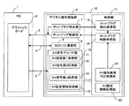
次に、本発明の実施形態について図面を参照して説明する。図2は本発明による電子機器の一実施形態の要部構成を示すブロック図である。本実施形態は、ソース機器としてのPC1と本発明による電子機器である、シンク機器としてのプロジェクタ18から構成されている。
PC1にはグラフィックボード2が設けられている。プロジェクタ18にはデジタル信号処理部6と制御部17が設けられている。Next, an embodiment of the present invention will be described with reference to the drawings. FIG. 2 is a block diagram showing a main configuration of an embodiment of an electronic device according to the present invention. The present embodiment includes a PC 1 as a source device and a
A
デジタル信号処理部6には、ホットプラグ検出部7、ホットプラグ制御部8、DDC/CI通信部9、およびAV信号デコード部10が設けられ、制御部17には、ホットプラグ検出処理部14、ホットプラグ制御処理部15、AV信号異常判定処理部16、および、AV設定情報処理部20が設けられている。AV信号デコード部10にはAV信号第1取得部11、AV信号第2取得部12、AV信号第n取得部13、および、AV設定情報取得部19が設けられている。
グラフィックボード2とデジタル信号処理部6とは、ホットプラグ検出ライン3、DDC/CI通信ライン4、および、映像/音声信号ライン5で接続されている。これらは、HDMIケーブル(不図示)内に設けられるもので、グラフィックボード2とデジタル信号処理部6は実際にはHDMIケーブルにより接続されている。The digital
The
プロジェクタ18には図2に示した構成の他に、音声を再生するための構成や映像を投写するための投写光学系、およびEDIDを格納する蓄積部などが設けられているがこれらはすべて一般的な構成のものであり、また、本発明の動作には特に関与しないため、図示および説明は省略する。
ホットプラグ検出ライン3は、PC1側ではPC1内部の電源にプルアップされており、シンク機器であるプロジェクタ18側がH(High)/L(Low)レベルの制御を行う。DDC/CI通信ライン4はEDIDのやり取りを行う際に用いられる。In addition to the configuration shown in FIG. 2, the
The hot plug detection line 3 is pulled up to the power supply inside the PC1 on the PC1 side, and the
デジタル信号処理部6は、ホットプラグ検出、ホットプラグ制御、DDC/CI通信、音声信号および映像信号を含むAV信号のデコードを行う。
ホットプラグ制御部8は、PC1のグラフィックボード2へのホットプラグ検出ライン3のH/Lの状態を制御し、ホットプラグ検出部7は、PC1のグラフィックボード2へのホットプラグ検出ライン3を検出してホットプラグ検出処理部14へ検出結果を出力する。DDC/CI通信部9は、DDC/CI通信ライン4を介してPC1のグラフィックボード2とHDMI認証、EDIDのやりとりを行う。The digital
The hot
AV信号デコード部10は、映像/音声信号ライン5を介して送られてきたAV信号をデコードして映像信号および音声信号とする。AV信号第1取得部11、AV信号第2取得部12、および、AV信号第n取得部13は、デコードにより得られた映像信号および音声信号を構成する各種のパラメータを取得するものである。図2には3つの取得部しか示されていないが、音声信号および映像信号の各種パラメータに対応して設けられる構成であり、実際にはより多くの取得部が設けられる。
The AV
AV設定情報取得部19は、映像/音声信号ライン5を介してPC1のグラフィックボード2から送られてきた制御信号に示される設定情報を取得する。
制御部17に設けられるAV設定情報処理部20は、AV設定情報取得部19が取得した設定情報を記憶する。AV信号異常判定処理部16は、パラメータ取得部としての、AV信号第1取得部11、AV信号第2取得部12、および、AV信号第n取得部13により得られた音声信号および映像信号の各種パラメータがEDIDに応じているかを確認することによりAV信号が異常であるかを判定し、判定結果をホットプラグ制御処理部15へ出力する。ホットプラグ制御処理部15は、AV信号異常判定処理部16からAV信号が異常である旨の判定通知を受け付けると、ホットプラグ制御部8にホットプラグ検出ラインをHにさせる。ホットプラグ検出処理部14は、ホットプラグ検出部7からのホットプラグ検出ライン3の検出結果をホットプラグ制御処理部15へ送出し、ホットプラグ制御処理部15はこれによりホットプラグ検出ライン3の状態を確認する。The AV setting
The AV setting
次に、本実施形態の動作について説明する。
上述したように、AV信号第1取得部11、AV信号第2取得部12、および、AV信号第n取得部13は音声信号および映像信号の各種パラメータを取得し、AV信号異常判定処理部16は、取得された各種パラメータがEDIDに応じているかを確認する。また、AV設定情報処理部20には設定情報を記憶する。取得されるパラメータおよび設定情報にはさまざまな種類が考えられ、特に限定されるものではないが、理解を容易とするために、以下の説明においては、AV信号第1取得部11は音声信号の周波数を取得し、AV信号第2取得部12は音声Info Frameの有無を検出し、AV信号第n取得部13は、音声信号のビット幅を取得するものとし、AV信号異常判定処理部16はこれらがEDIDに応じているかを確認することとし、AV設定情報処理部20は設定情報としてAV MUTEを記憶することとして説明する。なお、本実施形態では、AV MUTE有のときは、音声を消音状態(MUTE)とし、表示映像を全面黒の表示状態にすることとする(映像/音声MUTEをONにする)。また、AV MUTE無のときは、外部装置(PC1など)から入力された映像/音声を再生する(映像/音声 MUTEをOFFにする)。なお、上記の設定に限定されず、例えば、音声または映像のどちらか一方(異常と判定された音声または映像のどちらか一方)を上記状態にしてもよい。また、表示映像は全面黒ではなく、プロジェクタ18内部に保存されているデータに基づき生成される画像を表示するようにしてもよい。Next, the operation of this embodiment will be described.
As described above, the AV signal
前提条件として、PC1のグラフィックボード2からHDMI信号が出力され、かつ、ホットプラグ検出ライン3、DDC/CI通信ライン4、映像/音声信号ライン5がHDMIケーブルによってプロジェクタ18に接続された状態とする。
PC1へのユーザー操作により、PC1は映像/音声信号ライン5に、AV MUTE情報をONにしたHDMI映像/音声信号を出力する。
PC1に接続されているHDMIケーブルをプロジェクタ18に接続すると、ホットプラグ検出部7が“H”を検出する。“H”を検出するとホットプラグ検出処理部14はソース機器が接続されたと認識し、ホットプラグ制御処理部15に通知する。As a prerequisite, the HDMI signal is output from the
Upon user operation on the PC 1, the PC 1 outputs an HDMI video / audio signal with AV MUTE information turned on to the video /
When the HDMI cable connected to the PC 1 is connected to the
ホットプラグ検出処理部14からの通知を受けたホットプラグ制御処理部15は、ホットプラグ制御部8に対してホットプラグ下げ上げを行うように指示する。
指示を受けたホットプラグ制御部8はホットプラグの下げ上げを行う。
グラフィックボード2は、ホットプラグの下げ上げを検知すると、DDC/CI通信ライン4を用いてプロジェクタ18の対応解像度、対応リフレッシュレート情報等を取得し、さらに、HDMI認証を行った後に対応解像度及び対応リフレッシュレートに応じた信号を出力する。Upon receiving the notification from the hot plug
Upon receiving the instruction, the hot
When the
プロジェクタ18は、PC1から出力された信号映像/音声ライン5からHDMI信号映像/音声が入力されると、信号判別を行い入力信号解像度、入力リフレッシュレートなどを求め映像を表示し、音声を出力するための最適な設定をプロジェクタ18内部のハードウェアに設定する。
また、プロジェクタ18は、HDMI映像/音声信号に付加されている音声INFO FRAMEの有無、および、音声INFO FRAME中の音声BIT幅情報を定期的に取得する。When the HDMI signal video / audio is input from the signal video /
Further, the
図3は、PC1とプロジェクタ18がHDMIケーブルで接続されているときに、制御部17により定期的に行われる制御動作を示すフローチャートである。
プロジェクタ18では、AV設定情報取得部19で受信したHDMI映像/音声信号中のAV MUTE情報を取得し、AV設定情報処理部20に記憶する。本実施形態の場合、AV MUTEありなので、映像/音声MUTEをONにしている(ステップ31)。FIG. 3 is a flowchart showing a control operation periodically performed by the
The
AV信号異常判定処理部16は、定期的に取得している音声Freq及び音声INFOFRAME情報を元に、[音声周波数(Freq)が規定以外]であるかを確認し(ステップ32)、[音声INFO FRAMEがあるか]を確認し(ステップ33)、[音声BIT幅情報が規定値以外]であるかを確認する(ステップ34)。なお、音声周波数は音声を再生するときに用いられる基準となる周波数(クロック周波数など)である。アナログ音声信号をデジタル音声信号に変換するときに用いられるサンプリング周波数に対応する周波数としてもよい。
ステップ32では音声周波数が44.1kHz/48kHz/32kHz/88.2kHz/768kHz/96kHz/176.4kHz/192kHz/64kHz/128kHz/256kHz/512kHz/1024kHz/352.8kHz/705.6kHz/1411.2kHz/384kHz/1536kHz以外であるかが確認される。また、ステップ34では音声INFO FRAME中の音声BIT幅情報が16bit/18bit/20bit/24bit以外であるかが確認される。The AV signal abnormality
In
ステップ32〜34の結果、音声周波数が規定内であり、音声INFO FRAMEがあり、音声BIT幅情報が規定値内であることが確認された場合にはステップ31に戻り、それ以外の場合にはAV異常判定処理部16はAV信号が異常状態と判断する。
このとき音声パケットもしくは音声INFOFRAME情報が異常状態のためプロジェクタ18からの音声出力は異常音もしくは音声が出力されない状態となる。
上記のように異常状態と判断されたため、ホットプラグの下げ上げを行うが、このとき、ホットプラグの下げ上げによるソース機器における映像/音声の出力再設定が想定されるため、乱れた映像もしくはノイズ音を出さないためにAV信号異常判定処理部16は映像/音声MUTEをONにする(ステップ35)。As a result of
At this time, since the voice packet or the voice INFOFRAME information is in an abnormal state, the voice output from the
Since it was determined to be in an abnormal state as described above, the hot plug is lowered, but at this time, it is assumed that the video / audio output of the source device will be reset by lowering the hot plug, resulting in distorted video or noise. The AV signal abnormality
次に、ホットプラグ制御処理部15にホットプラグ下げ上げの指示を行い(ステップ36)、ホットプラグ制御部8はホットプラグの下げ上げを行う。
ソース機器であるPC1では、ホットプラグが下げ上げされたことにより映像/音声の出力再設定が行われる。
映像/音声の出力再設定が行われたことにより、プロジェクタ18は、信号再判別を行う(ステップ37)。
次に、記憶したAV設定情報を確認する(ステップ38)。本実施形態の場合にはAV MUTE有であるため、映像/音声 MUTEを継続する(ステップ39)。ここで、確認したAV設定状態がAV MUTE無であれば、映像/音声 MUTEをOFFにする(ステップ40)。Next, the hot plug
In the source device PC1, the video / audio output is reset due to the hot plug being lowered.
Since the video / audio output has been reset, the
Next, the stored AV setting information is confirmed (step 38). In the case of this embodiment, since AV MUTE is present, the video / audio MUTE is continued (step 39). Here, if the confirmed AV setting state is no AV MUTE, the video / audio MUTE is turned off (step 40).
本実施形態では、音声が異常状態のためにシンク機器側で音声が出力されない場合に、シンク機器側でホットプラグの下げ上げを行うことによりソース機器に出力再設定を行わせることで、HDMIケーブルの抜き差しと同等な動作となり自動的に音声が出力されるようにする。
また、AV MUTE中に音声パケットが異常状態となった場合でも、AV MUTE状態を維持したまま自動的に異常状態を解消できる。
なお、ホットプラグの下げ上げを行っても音声パケットの異常状態となった場合は無限にホットプラグの下げ上げを行うことになる。このようなことを避けるために、所定の回数行っても音声パケットの異常状態が続く場合には下げ上げを行わないようにすることとしてもよい。In the present embodiment, when the sound is not output on the sink device side due to an abnormal state, the HDMI cable is made to reset the output on the source device by lowering the hot plug on the sink device side. The operation is the same as the insertion and removal of, and the sound is automatically output.
Further, even if the voice packet becomes an abnormal state during AV MUTE, the abnormal state can be automatically resolved while maintaining the AV MUTE state.
Even if the hot plug is lowered, if the voice packet becomes abnormal, the hot plug is lowered indefinitely. In order to avoid such a situation, if the abnormal state of the voice packet continues even after performing a predetermined number of times, the lowering may not be performed.
さらに、本実施形態ではHDMIを使用しているが、DVI、DPなどのようにHDMIと異なるインターフェースを使用する場合であっても、本実施形態と同様のシーケンス制御を導入する事が可能である。
さらに、本実施形態では図3に示される動作を定期的に行うこととしたが、ステップ39もしくはステップ40の後にステップ31に戻ることとしてもよい。
さらに、AV信号の各種パラメータとして、音声信号における、音声周波数、音声INFO FRAMEの有無、音声BIT幅情報を用いることとして説明した。映像信号のパラメータとしては、フィールド周波数や解像度などを用いることができ、AV信号異常判定部16はこれらによりAV信号(映像信号)が異常であるかを判定することとしてもよい。
本実施形態では、シンク機器としてプロジェクタ18を用いて説明したが、これに限定されず、ディスプレイやテレビなどの表示装置としてもよい。Further, although HDMI is used in this embodiment, it is possible to introduce the same sequence control as in this embodiment even when an interface different from HDMI such as DVI and DP is used. ..
Further, in the present embodiment, the operation shown in FIG. 3 is periodically performed, but the process may be returned to step 31 after
Further, it has been described that the voice frequency, the presence / absence of the voice INFORMATION FRAME, and the voice BIT width information in the voice signal are used as various parameters of the AV signal. As the parameters of the video signal, a field frequency, a resolution, or the like can be used, and the AV signal
In the present embodiment, the
1 PC
2 グラフィックボード
3 ホットプラグ検出ライン
4 DDC/CI通信ライン
5 映像/音声信号ライン
6 デジタル信号処理部
7 ホットプラグ検出部
8 ホットプラグ制御部
9 DDC/CI通信部
10 AV信号デコード部
11 AV信号第1取得部
12 AV信号第2取得部
13 AV信号第n取得部
14 ホットプラグ検出処理部
15 ホットプラグ制御処理部
16 AV信号異常判定処理部
17 制御部
18 プロジェクタ
20 AV設定情報処理部1 PC
2 Graphic board 3 Hot
Claims (6)
前記AV信号の各種のパラメータを取得するパラメータ取得部と、
前記設定情報を取得するAV設定情報取得部と、
前記取得した設定情報を記憶するAV設定情報処理部と、
前記パラメータ取得部により取得された各種のパラメータが前記EDIDに応じたものでない場合には前記ホットプラグ検出ラインの状態を変化させて前記ソース機器に前記EDIDの伝送を要求させ、その後送られてきた前記AV信号による音声再生および映像表示を行う際に前記AV設定情報処理部により記憶された設定情報に応じた音声再生および映像表示を行う制御部と、を有する電子機器。 The AV signal and the control signal are connected to a source device that requests EDID transmission according to the state of the hot plug detection line and transmits an AV signal according to the transmitted EDID and a control signal indicating setting information for the AV signal. It is an electronic device that reproduces audio and displays video according to the above.
A parameter acquisition unit that acquires various parameters of the AV signal, and
The AV setting information acquisition unit that acquires the setting information, and
The AV setting information processing unit that stores the acquired setting information and
When various parameters acquired by the parameter acquisition unit do not correspond to the EDID, the state of the hot plug detection line is changed to request the source device to transmit the EDID, and then the hot plug detection line is transmitted. electronic equipment and a control unit for performing audio reproduction and video display corresponding to the stored setting information by the AV setting information processing unit when performing audio reproduction and video display by the AV signal.
前記パラメータ取得部が取得するパラメータが音声を再生するときの基準となる周波数を含む、電子機器。In the electronic device according to claim 1,
An electronic device in which a parameter acquired by the parameter acquisition unit includes a reference frequency when reproducing audio.
前記パラメータ取得部が取得するパラメータが音声INFO FRAMEの有無を含む、電子機器。In the electronic device according to claim 1 or 2.
An electronic device in which the parameters acquired by the parameter acquisition unit include the presence or absence of audio INFORMATION FRAME.
前記パラメータ取得部が取得するパラメータが音声INFO FRAME中の音声BIT幅情報を含む、電子機器。In the electronic device according to claim 2.
An electronic device in which the parameter acquired by the parameter acquisition unit includes audio BIT width information in audio INFORMATION FRAME.
前記設定情報がAV MUTEである、電子機器。In the electronic device according to any one of claims 1 to 4.
An electronic device whose setting information is AV MUTE.
前記AV信号の各種のパラメータを取得し、
前記設定情報を取得し、
前記取得した設定情報を記憶し、
前記取得された各種のパラメータが前記EDIDに応じたものでない場合には前記ホットプラグ検出ラインの状態を変化させて前記ソース機器に前記EDIDの伝送を要求させ、その後送られてきた前記AV信号による音声再生および映像表示を行う際に前記記憶された設定情報に応じた音声再生および映像表示を行う、表示方法。 The AV signal and the control signal are connected to a source device that requests EDID transmission according to the state of the hot plug detection line and transmits an AV signal according to the transmitted EDID and a control signal indicating setting information for the AV signal. It is a display method performed by an electronic device that reproduces audio and displays video according to the above.
Acquire various parameters of the AV signal and
Acquire the above setting information and
The acquired setting information is stored and stored.
When the various acquired parameters do not correspond to the EDID, the state of the hot plug detection line is changed to request the source device to transmit the EDID, and then the AV signal sent is used. A display method for performing audio reproduction and video display according to the stored setting information when performing audio reproduction and video display.
Applications Claiming Priority (1)
| Application Number | Priority Date | Filing Date | Title |
|---|---|---|---|
| PCT/JP2017/009509 WO2018163358A1 (en) | 2017-03-09 | 2017-03-09 | Electronic device and display method |
Publications (2)
| Publication Number | Publication Date |
|---|---|
| JPWO2018163358A1 JPWO2018163358A1 (en) | 2020-01-23 |
| JP6884199B2 true JP6884199B2 (en) | 2021-06-09 |
Family
ID=63448926
Family Applications (1)
| Application Number | Title | Priority Date | Filing Date |
|---|---|---|---|
| JP2019504226A Active JP6884199B2 (en) | 2017-03-09 | 2017-03-09 | Electronic devices and display methods |
Country Status (2)
| Country | Link |
|---|---|
| JP (1) | JP6884199B2 (en) |
| WO (1) | WO2018163358A1 (en) |
Families Citing this family (1)
| Publication number | Priority date | Publication date | Assignee | Title |
|---|---|---|---|---|
| CN116134796A (en) * | 2020-07-16 | 2023-05-16 | 夏普Nec显示器解决方案株式会社 | Electronic device and connection inspection method |
Family Cites Families (7)
| Publication number | Priority date | Publication date | Assignee | Title |
|---|---|---|---|---|
| KR101092438B1 (en) * | 2004-08-05 | 2011-12-13 | 엘지전자 주식회사 | Cable broadcasting receiver and diagnostic method thereof |
| JP2006146048A (en) * | 2004-11-24 | 2006-06-08 | Canon Inc | Projection type projector |
| JP4794983B2 (en) * | 2005-10-31 | 2011-10-19 | パナソニック株式会社 | Audio output system control method and audio output system |
| JP4596052B2 (en) * | 2008-07-18 | 2010-12-08 | ソニー株式会社 | Content output device, content output method, and program |
| JP2012199643A (en) * | 2011-03-18 | 2012-10-18 | Panasonic Corp | Communication control system and sink device |
| JP2014204389A (en) * | 2013-04-09 | 2014-10-27 | 株式会社東芝 | Electronic apparatus |
| JP2017009783A (en) * | 2015-06-22 | 2017-01-12 | Necディスプレイソリューションズ株式会社 | Multi-display system, video display apparatus, method for preventing occurrence of display fault in video display apparatus, and program |
-
2017
- 2017-03-09 JP JP2019504226A patent/JP6884199B2/en active Active
- 2017-03-09 WO PCT/JP2017/009509 patent/WO2018163358A1/en active Application Filing
Also Published As
| Publication number | Publication date |
|---|---|
| WO2018163358A1 (en) | 2018-09-13 |
| JPWO2018163358A1 (en) | 2020-01-23 |
Similar Documents
| Publication | Publication Date | Title |
|---|---|---|
| US8199161B2 (en) | Image processing device and image processing method | |
| US8918829B2 (en) | Communication system and transmitting-receiving device | |
| EP2162823B1 (en) | Apparatus and method of receiving data | |
| US8199258B2 (en) | Receiving apparatus and control method thereof | |
| US20080252782A1 (en) | Signal Source Device | |
| JP4799254B2 (en) | Display device and display system | |
| US20140009678A1 (en) | Video display apparatus, video output appartus, control methods thereof, and video display sysyem | |
| JP2008219796A (en) | Data reproduction apparatus and transmitter | |
| US8717503B2 (en) | Audio output device connectable with plurality of devices and method of controlling the same | |
| US20240040079A1 (en) | Reception Device, Method for Controlling Reception Device, and Transmission/Reception System | |
| JP4799337B2 (en) | Display device, AV device, and display system including these | |
| JP2011259050A (en) | Hdmi connection device | |
| US9407873B2 (en) | Information processing apparatus, information processing method, and computer program product | |
| JP6884199B2 (en) | Electronic devices and display methods | |
| JP2009093696A (en) | Test system for information reproducing system | |
| JP2020036135A (en) | Video transmitting device, information processing method, and program | |
| JP6056176B2 (en) | Repeater equipment | |
| JP6417783B2 (en) | Data processing device | |
| JP5349663B2 (en) | Video processing apparatus and video processing method | |
| JP2011035452A (en) | Electronic device, and method of controlling electronic device | |
| JP5055651B2 (en) | Content transmission / reception system, content transmission / reception device, content reception device, program thereof, and authentication method thereof | |
| WO2010007751A1 (en) | Video data processing device and video data processing method | |
| JP2008167367A (en) | Transmission device |
Legal Events
| Date | Code | Title | Description |
|---|---|---|---|
| A621 | Written request for application examination |
Free format text: JAPANESE INTERMEDIATE CODE: A621 Effective date: 20190903 |
|
| A131 | Notification of reasons for refusal |
Free format text: JAPANESE INTERMEDIATE CODE: A131 Effective date: 20201006 |
|
| A521 | Written amendment |
Free format text: JAPANESE INTERMEDIATE CODE: A523 Effective date: 20201127 |
|
| TRDD | Decision of grant or rejection written | ||
| A01 | Written decision to grant a patent or to grant a registration (utility model) |
Free format text: JAPANESE INTERMEDIATE CODE: A01 Effective date: 20210427 |
|
| A61 | First payment of annual fees (during grant procedure) |
Free format text: JAPANESE INTERMEDIATE CODE: A61 Effective date: 20210511 |
|
| R150 | Certificate of patent or registration of utility model |
Ref document number: 6884199 Country of ref document: JP Free format text: JAPANESE INTERMEDIATE CODE: R150 |