JP6750194B2 - Medical image processing apparatus, medical image processing method, and medical observation system - Google Patents
Medical image processing apparatus, medical image processing method, and medical observation system Download PDFInfo
- Publication number
- JP6750194B2 JP6750194B2 JP2015124005A JP2015124005A JP6750194B2 JP 6750194 B2 JP6750194 B2 JP 6750194B2 JP 2015124005 A JP2015124005 A JP 2015124005A JP 2015124005 A JP2015124005 A JP 2015124005A JP 6750194 B2 JP6750194 B2 JP 6750194B2
- Authority
- JP
- Japan
- Prior art keywords
- image
- captured
- unit
- focus
- captured image
- Prior art date
- Legal status (The legal status is an assumption and is not a legal conclusion. Google has not performed a legal analysis and makes no representation as to the accuracy of the status listed.)
- Expired - Fee Related
Links
- 238000012545 processing Methods 0.000 title claims description 101
- 238000003672 processing method Methods 0.000 title claims description 8
- 239000002131 composite material Substances 0.000 claims description 144
- 238000000034 method Methods 0.000 claims description 110
- 230000008569 process Effects 0.000 claims description 78
- 238000011156 evaluation Methods 0.000 claims description 59
- 230000002194 synthesizing effect Effects 0.000 claims description 43
- 238000001514 detection method Methods 0.000 claims description 40
- 230000015572 biosynthetic process Effects 0.000 claims description 26
- 238000003786 synthesis reaction Methods 0.000 claims description 26
- 238000010586 diagram Methods 0.000 description 21
- 238000005516 engineering process Methods 0.000 description 19
- 230000003287 optical effect Effects 0.000 description 13
- 238000003384 imaging method Methods 0.000 description 12
- 239000000203 mixture Substances 0.000 description 12
- 230000006870 function Effects 0.000 description 11
- 239000013598 vector Substances 0.000 description 5
- 230000008859 change Effects 0.000 description 3
- 238000004891 communication Methods 0.000 description 3
- 230000000694 effects Effects 0.000 description 3
- 230000009466 transformation Effects 0.000 description 3
- 239000000470 constituent Substances 0.000 description 2
- 230000007423 decrease Effects 0.000 description 2
- 239000011159 matrix material Substances 0.000 description 2
- 230000002093 peripheral effect Effects 0.000 description 2
- 239000004065 semiconductor Substances 0.000 description 2
- 240000000220 Panda oleosa Species 0.000 description 1
- 235000016496 Panda oleosa Nutrition 0.000 description 1
- 210000004556 brain Anatomy 0.000 description 1
- 238000006243 chemical reaction Methods 0.000 description 1
- 230000000295 complement effect Effects 0.000 description 1
- 238000005286 illumination Methods 0.000 description 1
- 230000001678 irradiating effect Effects 0.000 description 1
- 239000004973 liquid crystal related substance Substances 0.000 description 1
- 229910044991 metal oxide Inorganic materials 0.000 description 1
- 150000004706 metal oxides Chemical class 0.000 description 1
- 238000012986 modification Methods 0.000 description 1
- 230000004048 modification Effects 0.000 description 1
- 238000012544 monitoring process Methods 0.000 description 1
- 230000001151 other effect Effects 0.000 description 1
- 230000004044 response Effects 0.000 description 1
- 238000001356 surgical procedure Methods 0.000 description 1
Images


Classifications
-
- G—PHYSICS
- G02—OPTICS
- G02B—OPTICAL ELEMENTS, SYSTEMS OR APPARATUS
- G02B21/00—Microscopes
- G02B21/36—Microscopes arranged for photographic purposes or projection purposes or digital imaging or video purposes including associated control and data processing arrangements
- G02B21/365—Control or image processing arrangements for digital or video microscopes
- G02B21/367—Control or image processing arrangements for digital or video microscopes providing an output produced by processing a plurality of individual source images, e.g. image tiling, montage, composite images, depth sectioning, image comparison
-
- A—HUMAN NECESSITIES
- A61—MEDICAL OR VETERINARY SCIENCE; HYGIENE
- A61B—DIAGNOSIS; SURGERY; IDENTIFICATION
- A61B1/00—Instruments for performing medical examinations of the interior of cavities or tubes of the body by visual or photographical inspection, e.g. endoscopes; Illuminating arrangements therefor
- A61B1/00002—Operational features of endoscopes
- A61B1/00004—Operational features of endoscopes characterised by electronic signal processing
- A61B1/00009—Operational features of endoscopes characterised by electronic signal processing of image signals during a use of endoscope
- A61B1/000094—Operational features of endoscopes characterised by electronic signal processing of image signals during a use of endoscope extracting biological structures
-
- A—HUMAN NECESSITIES
- A61—MEDICAL OR VETERINARY SCIENCE; HYGIENE
- A61B—DIAGNOSIS; SURGERY; IDENTIFICATION
- A61B1/00—Instruments for performing medical examinations of the interior of cavities or tubes of the body by visual or photographical inspection, e.g. endoscopes; Illuminating arrangements therefor
- A61B1/00002—Operational features of endoscopes
- A61B1/00004—Operational features of endoscopes characterised by electronic signal processing
- A61B1/00009—Operational features of endoscopes characterised by electronic signal processing of image signals during a use of endoscope
- A61B1/000095—Operational features of endoscopes characterised by electronic signal processing of image signals during a use of endoscope for image enhancement
-
- G—PHYSICS
- G02—OPTICS
- G02B—OPTICAL ELEMENTS, SYSTEMS OR APPARATUS
- G02B27/00—Optical systems or apparatus not provided for by any of the groups G02B1/00 - G02B26/00, G02B30/00
- G02B27/0075—Optical systems or apparatus not provided for by any of the groups G02B1/00 - G02B26/00, G02B30/00 with means for altering, e.g. increasing, the depth of field or depth of focus
-
- H—ELECTRICITY
- H04—ELECTRIC COMMUNICATION TECHNIQUE
- H04N—PICTORIAL COMMUNICATION, e.g. TELEVISION
- H04N23/00—Cameras or camera modules comprising electronic image sensors; Control thereof
- H04N23/50—Constructional details
- H04N23/555—Constructional details for picking-up images in sites, inaccessible due to their dimensions or hazardous conditions, e.g. endoscopes or borescopes
-
- H—ELECTRICITY
- H04—ELECTRIC COMMUNICATION TECHNIQUE
- H04N—PICTORIAL COMMUNICATION, e.g. TELEVISION
- H04N23/00—Cameras or camera modules comprising electronic image sensors; Control thereof
- H04N23/60—Control of cameras or camera modules
- H04N23/63—Control of cameras or camera modules by using electronic viewfinders
-
- H—ELECTRICITY
- H04—ELECTRIC COMMUNICATION TECHNIQUE
- H04N—PICTORIAL COMMUNICATION, e.g. TELEVISION
- H04N23/00—Cameras or camera modules comprising electronic image sensors; Control thereof
- H04N23/60—Control of cameras or camera modules
- H04N23/67—Focus control based on electronic image sensor signals
- H04N23/673—Focus control based on electronic image sensor signals based on contrast or high frequency components of image signals, e.g. hill climbing method
-
- H—ELECTRICITY
- H04—ELECTRIC COMMUNICATION TECHNIQUE
- H04N—PICTORIAL COMMUNICATION, e.g. TELEVISION
- H04N23/00—Cameras or camera modules comprising electronic image sensors; Control thereof
- H04N23/60—Control of cameras or camera modules
- H04N23/67—Focus control based on electronic image sensor signals
- H04N23/675—Focus control based on electronic image sensor signals comprising setting of focusing regions
-
- H—ELECTRICITY
- H04—ELECTRIC COMMUNICATION TECHNIQUE
- H04N—PICTORIAL COMMUNICATION, e.g. TELEVISION
- H04N23/00—Cameras or camera modules comprising electronic image sensors; Control thereof
- H04N23/60—Control of cameras or camera modules
- H04N23/67—Focus control based on electronic image sensor signals
- H04N23/676—Bracketing for image capture at varying focusing conditions
-
- H—ELECTRICITY
- H04—ELECTRIC COMMUNICATION TECHNIQUE
- H04N—PICTORIAL COMMUNICATION, e.g. TELEVISION
- H04N23/00—Cameras or camera modules comprising electronic image sensors; Control thereof
- H04N23/60—Control of cameras or camera modules
- H04N23/68—Control of cameras or camera modules for stable pick-up of the scene, e.g. compensating for camera body vibrations
- H04N23/681—Motion detection
- H04N23/6811—Motion detection based on the image signal
-
- H—ELECTRICITY
- H04—ELECTRIC COMMUNICATION TECHNIQUE
- H04N—PICTORIAL COMMUNICATION, e.g. TELEVISION
- H04N23/00—Cameras or camera modules comprising electronic image sensors; Control thereof
- H04N23/60—Control of cameras or camera modules
- H04N23/68—Control of cameras or camera modules for stable pick-up of the scene, e.g. compensating for camera body vibrations
- H04N23/682—Vibration or motion blur correction
- H04N23/683—Vibration or motion blur correction performed by a processor, e.g. controlling the readout of an image memory
-
- H—ELECTRICITY
- H04—ELECTRIC COMMUNICATION TECHNIQUE
- H04N—PICTORIAL COMMUNICATION, e.g. TELEVISION
- H04N23/00—Cameras or camera modules comprising electronic image sensors; Control thereof
- H04N23/70—Circuitry for compensating brightness variation in the scene
- H04N23/743—Bracketing, i.e. taking a series of images with varying exposure conditions
-
- H—ELECTRICITY
- H04—ELECTRIC COMMUNICATION TECHNIQUE
- H04N—PICTORIAL COMMUNICATION, e.g. TELEVISION
- H04N23/00—Cameras or camera modules comprising electronic image sensors; Control thereof
- H04N23/95—Computational photography systems, e.g. light-field imaging systems
- H04N23/958—Computational photography systems, e.g. light-field imaging systems for extended depth of field imaging
- H04N23/959—Computational photography systems, e.g. light-field imaging systems for extended depth of field imaging by adjusting depth of field during image capture, e.g. maximising or setting range based on scene characteristics
-
- A—HUMAN NECESSITIES
- A61—MEDICAL OR VETERINARY SCIENCE; HYGIENE
- A61B—DIAGNOSIS; SURGERY; IDENTIFICATION
- A61B1/00—Instruments for performing medical examinations of the interior of cavities or tubes of the body by visual or photographical inspection, e.g. endoscopes; Illuminating arrangements therefor
- A61B1/00163—Optical arrangements
- A61B1/00188—Optical arrangements with focusing or zooming features
-
- A—HUMAN NECESSITIES
- A61—MEDICAL OR VETERINARY SCIENCE; HYGIENE
- A61B—DIAGNOSIS; SURGERY; IDENTIFICATION
- A61B1/00—Instruments for performing medical examinations of the interior of cavities or tubes of the body by visual or photographical inspection, e.g. endoscopes; Illuminating arrangements therefor
- A61B1/04—Instruments for performing medical examinations of the interior of cavities or tubes of the body by visual or photographical inspection, e.g. endoscopes; Illuminating arrangements therefor combined with photographic or television appliances
-
- A—HUMAN NECESSITIES
- A61—MEDICAL OR VETERINARY SCIENCE; HYGIENE
- A61B—DIAGNOSIS; SURGERY; IDENTIFICATION
- A61B1/00—Instruments for performing medical examinations of the interior of cavities or tubes of the body by visual or photographical inspection, e.g. endoscopes; Illuminating arrangements therefor
- A61B1/06—Instruments for performing medical examinations of the interior of cavities or tubes of the body by visual or photographical inspection, e.g. endoscopes; Illuminating arrangements therefor with illuminating arrangements
- A61B1/0661—Endoscope light sources
- A61B1/0684—Endoscope light sources using light emitting diodes [LED]
-
- G—PHYSICS
- G02—OPTICS
- G02B—OPTICAL ELEMENTS, SYSTEMS OR APPARATUS
- G02B21/00—Microscopes
- G02B21/0004—Microscopes specially adapted for specific applications
- G02B21/0012—Surgical microscopes
Landscapes
- Engineering & Computer Science (AREA)
- Multimedia (AREA)
- Signal Processing (AREA)
- Physics & Mathematics (AREA)
- Health & Medical Sciences (AREA)
- Life Sciences & Earth Sciences (AREA)
- Optics & Photonics (AREA)
- Surgery (AREA)
- General Physics & Mathematics (AREA)
- Nuclear Medicine, Radiotherapy & Molecular Imaging (AREA)
- Medical Informatics (AREA)
- Veterinary Medicine (AREA)
- Public Health (AREA)
- Biophysics (AREA)
- General Health & Medical Sciences (AREA)
- Pathology (AREA)
- Radiology & Medical Imaging (AREA)
- Animal Behavior & Ethology (AREA)
- Biomedical Technology (AREA)
- Heart & Thoracic Surgery (AREA)
- Molecular Biology (AREA)
- Analytical Chemistry (AREA)
- Computer Vision & Pattern Recognition (AREA)
- Chemical & Material Sciences (AREA)
- Computing Systems (AREA)
- Theoretical Computer Science (AREA)
- Image Processing (AREA)
- Studio Devices (AREA)
- Endoscopes (AREA)
- Image Analysis (AREA)
Description
本技術は、医療用画像処理装置、医療用画像処理方法、及び、医療用観察システムに関し、特に、例えば、ディープフォーカスの画像を、低遅延、かつ、高フレームレートで得ることができるようにする医療用画像処理装置、医療用画像処理方法、及び、医療用観察システムに関する。 The present technology relates to a medical image processing apparatus, a medical image processing method, and a medical observation system, and in particular, enables deep-focus images to be obtained with low delay and high frame rate. The present invention relates to a medical image processing device, a medical image processing method, and a medical observation system.
例えば、医療用顕微鏡で撮影される撮影画像の被写界深度は浅く、実空間においてフォーカスが合っているフォーカス位置(フォーカス面)から、少しでも奥行きが異なる被写体は、ぼけた画像になる。 For example, an image captured by a medical microscope has a shallow depth of field, and a subject whose depth is slightly different from a focus position (focus plane) in focus in a real space becomes a blurred image.
例えば、脳外科手術等において、医療用顕微鏡で得られる撮影画像では、周辺部に、手前にある被写体が映り、中心部に、幾分、奥にある注目する被写体(術部等)が映る。このとき、撮影画像の中央部に映る被写体がインフォーカスになるように、フォーカスが調整されると、撮影画像の周辺部に映る被写体がぼけ、被写体の観察性や、医療用顕微鏡の操作性に影響することがある。 For example, in a brain surgery or the like, in a photographed image obtained by a medical microscope, a subject in the foreground appears in the peripheral portion, and a subject in the back (a surgical site or the like) in the center appears somewhat. At this time, if the focus is adjusted so that the subject in the center of the captured image will be in focus, the subject in the peripheral portion of the captured image will be blurred, which may affect the observability of the subject and the operability of the medical microscope. May affect.
そこで、例えば、フォーカス位置(焦点距離)を変更して画像を高速撮影し、その結果得られる複数の画像から、ディープフォーカスの画像(全焦点画像)を得る実時間全焦点顕微鏡カメラが提案されている(例えば、特許文献1を参照)。 Therefore, for example, a real-time omnifocal microscope camera has been proposed in which a focus position (focal length) is changed, an image is captured at high speed, and a deep-focus image (omnifocal image) is obtained from a plurality of images obtained as a result. (For example, see Patent Document 1).
ところで、医療用顕微鏡等の医療機器において、施術等を行う医者等のユーザに、画像を提供する場合には、医療という分野の性質上、低遅延であること、及び、画像のフレームレートが、高フレームレートであることが要求される。 By the way, in a medical device such as a medical microscope, in the case of providing an image to a user such as a doctor who performs an operation, in the nature of the field of medical treatment, low delay, and an image frame rate, High frame rate is required.
本技術は、このような状況に鑑みてなされたものであり、ディープフォーカスの画像を、低遅延、かつ、高フレームレートで得ることができるようにするものである。 The present technology has been made in view of such circumstances, and makes it possible to obtain a deep-focus image with a low delay and a high frame rate.
本技術の医療用画像処理装置は、フォーカス位置を変えながら、生体を撮影することにより得られる複数の撮影画像を合成し、合成画像を生成する合成部であって、直前に得られた合成画像の画素、及び、最新の撮影画像の画素のうちの、フォーカスが合っている画素を選択することにより、前記直前に得られた合成画像と、前記最新の撮影画像とを合成し、最新の合成画像を生成する合成部を備え、前記撮影画像及び前記合成画像に含まれる被写体の動き検出において検出される動きの大きさが閾値以上であることを合成制限条件として、合成を制限すべき合成制限条件が満たされる場合、前記合成部は、1の撮影画像を、前記合成画像として出力する医療用画像処理装置である。 The medical image processing apparatus of the present technology is a combining unit that combines a plurality of captured images obtained by capturing an image of a living body while changing the focus position and generates a combined image. Of the pixel and the pixel of the latest captured image, the in-focus pixel is selected to synthesize the synthesized image obtained immediately before and the latest captured image, and the latest synthesized image is synthesized. A synthesis restriction that includes a synthesis unit that generates an image, and limits the synthesis with a synthesis restriction condition that the magnitude of motion detected in motion detection of a subject included in the captured image and the synthetic image is equal to or greater than a threshold value. When the condition is satisfied, the combining unit is a medical image processing apparatus that outputs one captured image as the combined image.
本技術の医療用画像処理方法は、医療用画像処理装置が、フォーカス位置を変えながら、生体を撮影することにより得られる複数の撮影画像を合成し、合成画像を生成する合成処理であって、直前に得られた合成画像の画素、及び、最新の撮影画像の画素のうちの、フォーカスが合っている画素を選択することにより、前記直前に得られた合成画像と、前記最新の撮影画像とを合成し、最新の合成画像を生成する合成処理を行い、前記撮影画像及び前記合成画像に含まれる被写体の動き検出において検出される動きの大きさが閾値以上であることを合成制限条件として、合成を制限すべき合成制限条件が満たされる場合、1の撮影画像を、前記合成画像として出力する医療用画像処理方法である。 The medical image processing method of the present technology is a synthesizing process in which a medical image processing apparatus synthesizes a plurality of captured images obtained by capturing an image of a living body while changing a focus position, and generates a synthetic image. By selecting a focused pixel from the pixels of the composite image obtained immediately before and the pixels of the latest captured image, the composite image obtained immediately before and the latest captured image Is performed to perform a synthesizing process for generating the latest synthesized image, and the magnitude of the motion detected in the motion detection of the subject included in the captured image and the synthesized image is equal to or more than a threshold, as a synthesizing restriction condition, In the medical image processing method, one captured image is output as the composite image when the composite restriction condition for restricting the composite is satisfied.
本技術の医療用観察システムは、フォーカス位置を変えながら、生体を撮影する撮影部と、前記撮影部により撮影された複数の撮影画像を合成し、合成画像を生成する合成部であって、直前に得られた合成画像の画素、及び、最新の撮影画像の画素のうちの、フォーカスが合っている画素を選択することにより、前記直前に得られた合成画像と、前記最新の撮影画像とを合成し、最新の合成画像を生成する合成部とを備え、前記撮影画像及び前記合成画像に含まれる被写体の動き検出において検出される動きの大きさが閾値以上であることを合成制限条件として、合成を制限すべき合成制限条件が満たされる場合、前記合成部は、1の撮影画像を、前記合成画像として出力する医療用観察システムである。
The medical observation system of the present technology is a combining unit that combines a photographing unit that photographs a living body while changing a focus position and a plurality of photographed images photographed by the photographing unit to generate a combined image. By selecting the focused pixel from the pixels of the composite image obtained in
本技術の医療用画像処理装置、医療用画像処理方法、及び、医療用観察システムにおいては、フォーカス位置を変えながら、生体を撮影することにより得られる複数の撮影画像が合成され、合成画像が生成される。合成画像の生成では、直前に得られた合成画像の画素、及び、最新の撮影画像の画素のうちの、フォーカスが合っている画素を選択することにより、前記直前に得られた合成画像と、前記最新の撮影画像とを合成し、最新の合成画像が生成され、前記撮影画像及び前記合成画像に含まれる被写体の動き検出において検出される動きの大きさが閾値以上であることを合成制限条件として、合成を制限すべき合成制限条件が満たされる場合、1の撮影画像が、前記合成画像として出力される。 In the medical image processing apparatus, the medical image processing method, and the medical observation system of the present technology, a plurality of captured images obtained by capturing an image of a living body while changing the focus position are combined to generate a combined image. To be done. In the generation of the composite image, the pixel of the composite image obtained immediately before, and of the pixels of the latest captured image, by selecting the pixel in focus, the composite image obtained immediately before, The latest synthetic image is synthesized to generate the newest synthetic image , and the synthetic restriction condition is that the magnitude of motion detected in motion detection of the subject included in the synthetic image and the synthetic image is equal to or greater than a threshold value. As a result, when the combination restriction condition for restricting the combination is satisfied, one captured image is output as the composite image.
なお、医療用画像処理装置や医療用観察システムは、独立した装置であっても良いし、1つの装置を構成している内部ブロックであっても良い。 The medical image processing device and the medical observation system may be independent devices or may be internal blocks that form one device.
本技術によれば、例えば、ディープフォーカスの画像を、低遅延、かつ、高フレームレートで得ることができる。 According to the present technology, for example, a deep focus image can be obtained with low delay and high frame rate.
なお、ここに記載された効果は必ずしも限定されるものではなく、本開示中に記載されたいずれかの効果であってもよい。 Note that the effects described here are not necessarily limited and may be any effects described in the present disclosure.
<本技術を適用した医療用観察システムの一実施の形態> <One Embodiment of Medical Observation System to which the Present Technology is Applied>
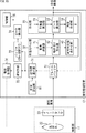
図1は、本技術を適用した医療用観察システムの一実施の形態の構成例を示すブロック図である。 FIG. 1 is a block diagram showing a configuration example of an embodiment of a medical observation system to which the present technology is applied.
図1の医療用観察システムは、例えば、医療用の内視鏡システムや、医療用電子顕微鏡(手術用顕微鏡)等の、生体を観察する機能を有する医療機器に適用することができる。 The medical observation system of FIG. 1 can be applied to a medical device having a function of observing a living body, such as a medical endoscope system and a medical electron microscope (surgical microscope).
図1において、医療用観察システムは、撮影部11、信号処理装置12、及び、表示装置13を有する。
In FIG. 1, the medical observation system includes an
撮影部11は、例えば、施術を施す人体の術部等の生体である被写体を照明しながら撮影し、その撮影により得られる生体画像である撮影画像を、信号処理装置12に供給する。
The photographing
撮影部11は、光源21、光学系22、及び、イメージセンサ23を有する。
The
光源21は、例えば、LED (Light Emitting Diode)等で構成され、被写体を照明する光を発する。
The
光学系22は、図示せぬ鏡筒に設けられており、フォーカスレンズや絞り等の光学部品で構成される。光学系22は、光源21が発する光が被写体で反射されることにより入射する被写体光(反射光)を、イメージセンサ23上に集光する。
The
イメージセンサ23は、例えば、CMOS(Complementary Metal Oxide Semiconductor)センサであり、光学系22からの被写体光を受光し、光電変換を行うことで、被写体を撮影する。イメージセンサ23が被写体を撮影することにより得られる撮影画像は、信号処理装置12に供給される。
The
なお、撮影部11では、撮影画像として、2D(Dimension)画像を撮影することもできるし、左眼用の画像(L(Left)画像)と右眼用の画像(R(Right)画像)とからなる3D画像を撮影することもできる。
Note that the
撮影部11において、3D画像を撮影する場合、撮影部11には、図中、点線で示すように、L画像を撮影する光学系22及びイメージセンサ23と、R画像を撮影する光学系22及びイメージセンサ23とが設けられる。
When a 3D image is captured by the
また、撮影部11において、3D画像を撮影する場合、信号処理装置12では、例えば、L画像と、R画像とのそれぞれに、同様の処理が施される。
Further, when the
以下では、説明を簡単にするため、撮影部11では、撮影画像として、2D画像が撮影されることとする。
In the following, in order to simplify the description, it is assumed that the
信号処理装置12は、撮影部11からの撮影画像に必要な信号処理を施し、その信号処理の結果得られる画像を、表示装置13に供給する。
The
その他、信号処理装置12は、必要に応じて、撮影部11を制御する。
In addition, the
すなわち、信号処理装置12は、例えば、光源21を制御することにより、光源21による照明の明るさを制御する。また、信号処理装置12は、例えば、光学系22を制御することにより、絞りや、フォーカス(位置)、ズームを調整する。さらに、信号処理装置12は、例えば、イメージセンサ23を制御することにより、撮影画像のフレームレートや、撮影画像を撮影するときの露光時間(シャッタスピード)を制御する。
That is, the
表示装置13は、信号処理装置12から供給される画像を表示する。表示装置13としては、例えば、信号処理装置12と一体となったディスプレイや、信号処理装置12とは別個の据え置き型のディスプレイ、ヘッドマウントディスプレイ等を採用することができる。
The
<信号処理装置12の第1の構成例>
<First Configuration Example of
図2は、図1の信号処理装置12の第1の構成例を示すブロック図である。
FIG. 2 is a block diagram showing a first configuration example of the
図2において、信号処理装置12は、フレームバッファ31、位置合わせ部32、合成部33、駆動制御部34、及び、制御部35を有する。
In FIG. 2, the
フレームバッファ31には、撮影部11(のイメージセンサ23)から、撮影画像が供給されるとともに、合成部33から、後述する合成画像が供給される。
A captured image is supplied from (the
フレームバッファ31は、撮影部11からの撮影画像や、合成部33からの合成画像を一時記憶する。
The
ここで、撮影部11では、後述する駆動制御部34による光学系22の制御にしたがって、フォーカス位置を変えながら、撮影画像が、表示装置13で表示される画像のフレームレート以上のフレームレートで(高速)撮影される。
Here, in the
したがって、撮影部11からフレームバッファ31には、フォーカス位置が異なる複数の撮影画像が供給され、フレームバッファ31は、そのような、フォーカス位置が異なる複数の撮影画像を記憶する。
Therefore, a plurality of photographed images with different focus positions are supplied from the photographing
位置合わせ部32は、フレームバッファ31に記憶された直前の合成画像と最新の撮影画像との位置合わせを行い、その位置合わせ後の合成画像と撮影画像を、合成部33に供給する。
The
すなわち、位置合わせ部32は、画角調整部41、動きぼけ除去部42、及び、被写体位置合わせ部43を有する。
That is, the
画角調整部41は、合成画像及び撮影画像について、画角を調整し、画角の調整後の合成画像と撮影画像とを、動きぼけ除去部42に供給する。
The angle-of-
動きぼけ除去部42は、画角調整部41からの撮影画像に生じている動きぼけを除去し、その動きぼけの除去後の撮影画像を、合成画像とともに、被写体位置合わせ部43に供給する。
The motion
被写体位置合わせ部43は、動きぼけ除去部42からの合成画像及び撮影画像について、動きを検出し、その動きの検出結果に基づいて、合成画像と撮影画像との位置合わせを行う。
The subject
すなわち、被写体位置合わせ部43は、撮影画像に映る被写体に対して、合成画像に映る、同一の被写体の位置を合わせる位置合わせを行う。
That is, the
そして、被写体位置合わせ部43は、位置合わせ後の合成画像及び撮影画像を、合成部33に供給する。
Then, the subject
合成部33は、位置合わせ部32(の被写体位置合わせ部43)からの合成画像と撮影画像とを合成することにより、最新の合成画像を生成する。
The synthesizing
すなわち、合成部33は、特徴量算出部51、ピーク算出部52、及び、画像合成部53を有する。
That is, the synthesizing
特徴量算出部51は、位置合わせ部33からの合成画像及び撮影画像のそれぞれの画素について、フォーカスが合っている(インフォーカスになっている)程度を表す特徴量(以下、合焦特徴量ともいう)を算出し、ピーク算出部52に供給する。
The feature
ピーク算出部52は、合成画像及び撮影画像のそれぞれの同一の位置の画素の合焦特徴量のピークを算出する。すなわち、ピーク算出部52は、合成画像及び撮影画像のそれぞれの同一の位置の画素の合焦特徴量のうちの大きい方の合焦特徴量を検出し、その検出結果(以下、ピーク検出結果ともいう)を、画像合成部53に供給する。
The
画像合成部53は、ピーク算出部52からのピーク検出結果に応じて、位置合わせ部32からの合成画像と撮影画像とを合成することにより、最新の合成画像を生成する。
The
画像合成部53で得られた(最新の)合成画像は、フレームバッファ31に供給されるとともに、必要に応じて、表示装置13(図1)に出力される。
The (latest) combined image obtained by the
駆動制御部34は、光学系22を駆動することにより、フォーカス位置を移動させる。
The
制御部35は、信号処理装置12全体を制御する。
The
<撮影画像の撮影、及び、合成画像の生成の概要> <Overview of shooting a captured image and generating a composite image>
図3は、撮影部11での撮影画像の撮影、及び、信号処理装置12での合成画像の生成の概要を説明する図である。
FIG. 3 is a diagram for explaining an outline of photographing of a photographed image by the photographing
図3では、撮影部11において、例えば、120Hzのフレームレートで、撮影画像(のフレーム)F1,F2,F3,...が撮影されている。
In FIG. 3, the photographing
また、図3では、撮影画像を撮影するときのフォーカス位置が、フレームごとに、フォーカス位置pos1,pos2,pos3,pos4の4個の位置に、周期的に移動されている。 Further, in FIG. 3, the focus position when capturing the captured image is periodically moved to four positions of focus positions pos1, pos2, pos3, and pos4 for each frame.
ここで、フォーカス位置pos1,pos2,pos3,pos4は、異なっており、図3では、式pos1<pos2<pos3<pos4で表される関係を有する。 Here, the focus positions pos1, pos2, pos3, pos4 are different, and in FIG. 3, they have the relationship represented by the expression pos1<pos2<pos3<pos4.
撮影部11では、上述のように、フォーカス位置を、フォーカス位置pos1,pos2,pos3,pos4に、周期的に変えながら、撮影画像F1,F2,F3,...が撮影されている。
As described above, the
その結果、撮影画像F1は、フォーカス位置pos1の画像(フォーカス位置pos1にフォーカスがあった画像)に、撮影画像F2は、フォーカス位置pos2の画像に、撮影画像F3は、フォーカス位置pos3の画像に、撮影画像F4は、フォーカス位置pos4の画像に、それぞれなっている。 As a result, the captured image F1 is the image at the focus position pos1 (the image in focus at the focus position pos1), the captured image F2 is the image at the focus position pos2, and the captured image F3 is the image at the focus position pos3. The captured image F4 is an image at the focus position pos4.
そして、撮影画像F5は、フォーカス位置pos1の画像になっており、以下、以降の撮影画像も同様に、フォーカス位置が周期的に異なる画像になっている。 Then, the captured image F5 is the image at the focus position pos1, and the subsequent captured images are also images at which the focus positions are periodically different.
信号処理装置12では、原理的には、フォーカス位置pos1,pos2,pos3,pos4の4フレームの撮影画像等の、フォーカス位置が異なる複数の撮影画像を合成することにより、ディープフォーカスの合成画像を生成する。
In principle, the
フォーカス位置pos1,pos2,pos3,pos4の撮影画像等の、フォーカス位置が異なる複数の撮影画像を合成して、ディープフォーカスの合成画像を生成するEDoF(Extended Depth of Field)の方法としては、例えば、第1の合成方法や第2の合成方法を採用することができる。 As a method of EDoF (Extended Depth of Field) for generating a deep focus composite image by combining a plurality of captured images with different focus positions, such as the captured images of the focus positions pos1, pos2, pos3, pos4, for example, The first combining method and the second combining method can be adopted.
第1の合成方法では、フォーカス位置pos1ないしpos4の撮影画像のうちの最新の撮影画像であるフォーカス位置pos4の撮影画像に対して、他のフォーカス位置pos1ないしpos3の撮影画像それぞれの位置合わせが行われる。 In the first combining method, the captured image at the focus position pos4, which is the latest captured image among the captured images at the focus positions pos1 to pos4, is aligned with the captured images at the other focus positions pos1 to pos3. Be seen.
そして、位置合わせ後のフォーカス位置pos1ないしpos4の撮影画像の各画素について、合焦特徴量が最大(ピーク)のフォーカス位置の撮影画像の画素が、合成画像の画素として選択され、そのような画素で構成される合成画像が生成される。 Then, for each pixel of the captured images at the focus positions pos1 to pos4 after alignment, the pixel of the captured image at the focus position with the maximum (peak) focus feature amount is selected as a pixel of the composite image, and such pixels are selected. A composite image composed of is generated.
第2の合成方法では、例えば、最初に撮影されたフォーカス位置pos1の撮影画像F1が、そのまま、合成画像とされる。そして、その合成画像(直前の合成画像)と、次に撮影されたフォーカス位置pos2の撮影画像F2とが合成される。 In the second combining method, for example, the first captured image F1 at the focus position pos1 is directly used as a combined image. Then, the composite image (the previous composite image) and the captured image F2 of the focus position pos2 captured next time are combined.
すなわち、最新の撮影画像であるフォーカス位置pos2の撮影画像F2に対して、直前の合成画像の位置合わせが行われる。 That is, the position of the immediately preceding composite image is aligned with the captured image F2 at the focus position pos2, which is the latest captured image.
そして、位置合わせ後のフォーカス位置pos2の撮影画像F2及び合成画像の各画素について、合焦特徴量が最大(大きい方)の撮影画像F2又は合成画像の画素が、最新の合成画像C1の画素として選択され、そのような画素で構成される最新の合成画像C1が生成される。 Then, for each pixel of the captured image F2 and the combined image at the focus position pos2 after alignment, the pixel of the captured image F2 or the combined image with the maximum (larger) focus feature amount is the pixel of the latest combined image C1. The latest composite image C1 selected and composed of such pixels is generated.
フォーカス位置pos2の撮影画像F2の次に撮影されたフォーカス位置pos3の撮影画像F3については、合成画像C1が、直前の合成画像C1となり、その合成画像C1と、フォーカス位置pos3の撮影画像F3(最新の撮影画像)とが、同様に合成され、最新の合成画像C2が生成される。 Regarding the captured image F3 of the focus position pos3 that is captured next to the captured image F2 of the focus position pos2, the composite image C1 becomes the immediately preceding composite image C1, and the composite image C1 and the captured image F3 of the focus position pos3 (latest And the photographed image) are similarly synthesized to generate the latest synthesized image C2.
フォーカス位置pos3の撮影画像F3の次に撮影されたフォーカス位置pos4の撮影画像F4については、合成画像C2が、直前の合成画像C2となり、その合成画像C2と、フォーカス位置pos4の撮影画像F4とが、同様に合成され、最新の合成画像C3が生成される。 Regarding the captured image F4 at the focus position pos4 captured next to the captured image F3 at the focus position pos3, the composite image C2 becomes the immediately preceding composite image C2, and the composite image C2 and the captured image F4 at the focus position pos4 are obtained. , Is similarly synthesized, and the latest synthesized image C3 is generated.
以下、同様に、第2の合成方法では、直前の合成画像と、最新の撮影画像とが合成されることにより、最新の合成画像が生成される。 Hereinafter, similarly, in the second combining method, the latest combined image is generated by combining the immediately previous combined image and the latest captured image.
フォーカス位置pos1ないしpos4の撮影画像を、第1の合成方法で合成することにより得られる合成画像と、第2の合成方法で得られる合成画像C3とは、いずれも、フォーカス位置pos1からフォーカス位置pos4までを被写界深度に含むディープフォーカスの画像になっている。 The combined image obtained by combining the photographed images at the focus positions pos1 to pos4 by the first combining method and the combined image C3 obtained by the second combining method are both from the focus position pos1 to the focus position pos4. It is a deep focus image that includes up to the depth of field.
また、第1及び第2の合成方法のいずれであっても、合成画像は、フォーカス位置pos1ないしpos4の撮影画像が撮影されてから得ることができる。 Further, in any of the first and second combining methods, the combined image can be obtained after the captured images at the focus positions pos1 to pos4 are captured.
但し、第1の合成方法では、フォーカス位置pos1ないしpos4の撮影画像の4フレームの画像が、合成画像を生成する合成処理(位置合わせ部32で行われる位置合わせの処理、及び、合成部33で行われる合成の処理)の対象となる。
However, in the first synthesizing method, the synthesizing process (the locating process performed by the locating
一方、第2の合成方法では、直前の合成画像及び最新の撮影画像の2フレームの画像が、合成処理の対象となる。 On the other hand, in the second synthesizing method, two frames of the immediately preceding synthetic image and the latest captured image are subjected to the synthesizing process.
したがって、第1及び第2の合成方法については、得られる合成画像の被写界深度に差はないが、合成画像の生成に、3フレーム以上の撮影画像が用いられる場合には、第2の合成方法の方が、第1の合成方法よりも、合成処理を、短時間で行うことができる。 Therefore, regarding the first and second combining methods, there is no difference in the depth of field of the obtained combined image, but when the captured images of three frames or more are used for generating the combined image, the second combination is used. The synthesizing method can perform the synthesizing process in a shorter time than the first synthesizing method.
以上のように、第2の合成方法によれば、合成処理を短時間で行うことができるので、ディープフォーカスの画像である合成画像を、低遅延、かつ、高フレームレートで得ることができる。 As described above, according to the second synthesizing method, the synthesizing process can be performed in a short time, so that a synthetic image that is a deep-focused image can be obtained with a low delay and a high frame rate.
したがって、前述したように、医療機器において、施術等を行う医者等のユーザに、画像を提供する場合には、医療という分野の性質上、低遅延であること、及び、高フレームレートであることが要求されるが、第2の合成方法によれば、ディープフォーカスの画像を、低遅延、かつ、高フレームレートで提供することができる。その結果、被写体の観察性(被写体の観察しやすさ)や、被写体に対する施術のしやすさ等を向上させることができる。 Therefore, as described above, in the case of providing an image to a user such as a doctor who performs an operation on a medical device, the delay is low and the frame rate is high due to the nature of the medical field. However, according to the second synthesizing method, it is possible to provide a deep-focus image with low delay and high frame rate. As a result, it is possible to improve the observability of the subject (ease of observing the subject), the ease of performing the treatment on the subject, and the like.
さらに、第2の合成方法によれば、撮影部11のフォーカス駆動が低速で、時間を要する場合であっても、短時間で合成処理を行い、ディープフォーカスの画像を迅速に得ることが可能となる。
Furthermore, according to the second combining method, even if the focus driving of the
なお、図3に示したように、撮影部11において、フォーカス位置を、フォーカス位置pos1,pos2,pos3,pos4に、周期的に変えながら、120Hzのフレームレートで、撮影画像を撮影する場合には、信号処理装置12において、フォーカス位置pos1,pos2,pos3,pos4の4フレームの撮影画像が撮影されるごとに、その4フレームの撮影画像を合成した1フレームの合成画像を生成することができる。この場合、1のフォーカス位置の撮影画像の(ほぼ)4倍の被写界深度の合成画像であって、30Hzのフレームレートの合成画像を得ることができる。
Note that, as shown in FIG. 3, in the photographing
また、図3に示したように、撮影部11において、フォーカス位置を、フォーカス位置pos1,pos2,pos3,pos4に、周期的に変えながら、120Hzのフレームレートで、撮影画像を撮影する場合には、信号処理装置12において、最新の撮影画像が撮影されるごとに、その最新の撮影画像を含む過去4フレームの撮影画像を合成した1フレームの合成画像を生成することができる。この場合、1のフォーカス位置の撮影画像の(ほぼ)4倍の被写界深度の合成画像であって、120Hzのフレームレートの合成画像を得ることができる。
Further, as shown in FIG. 3, in the photographing
ここで、図1の医療用観察システムでは、第1及び第2の合成方法のいずれをも採用することができるが、以下では、第1及び第2の合成方法のうちの、例えば、第2の合成方法を例として、説明を行う。 Here, in the medical observation system of FIG. 1, both the first and second synthesizing methods can be adopted. However, in the following, for example, the second and the second synthesizing methods are used. The description will be given by taking the synthesizing method of 1.
<位置合わせ部32及び合成部33の処理>
<Processing of
図4は、図2の位置合わせ部32及び合成部33の処理の例を説明する図である。
FIG. 4 is a diagram illustrating an example of processing of the
図3で説明したように、撮影部11は、フォーカス位置を変えながら、撮影画像を撮影する。
As described with reference to FIG. 3, the
図4では、被写体obj1とobj2とが映る撮影画像が、時刻t0,t1,t2に撮影されている。 In FIG. 4, captured images showing the objects obj1 and obj2 are captured at times t 0 , t 1 , and t 2 .
時刻t0ないしt2それぞれの撮影画像では、フォーカス位置が異なっており、そのため、時刻t0の撮影画像では、被写体obj1は、インフォーカスになっており、被写体obj2は、ピンぼけ(アウトフォーカス)になっている。また、時刻t1及びt2の撮影画像では、被写体obj1は、ピンぼけになっており、被写体obj2は、インフォーカスになっている。 The focus positions are different in the captured images at times t 0 to t 2, so that in the captured image at time t 0 , the subject obj1 is in focus and the subject obj2 is out of focus. ing. Further, in the captured images at the times t 1 and t 2 , the subject obj1 is out of focus and the subject obj2 is in focus.
ここで、説明を簡単にするため、図4では、時刻t0の撮影画像を、直前の合成画像とするとともに、時刻t1の撮影画像を、最新の撮影画像として、位置合わせ部32及び合成部33の処理を説明する。
Here, in order to simplify the description, in FIG. 4, the captured image at time t 0 is set as the immediately preceding synthesized image, and the captured image at time t 1 is set as the latest captured image as well as the
位置合わせ部32では、最新の撮影画像としての時刻t1の撮影画像に対して、直前の合成画像としての時刻t0の撮影画像の位置を合わせる位置合わせが行われる。
In the
位置合わせは、時刻t0及びt1の撮影画像のそれぞれに映る同一の被写体どうしが、極力重なり合うように行われる。 The alignment is performed so that the same subjects appearing in the captured images at times t 0 and t 1 overlap as much as possible.
すなわち、位置合わせ部32では、時刻t0及びt1の撮影画像のそれぞれに映る同一の被写体obj1どうしと、被写体obj2どうしとが、それぞれ、極力重なり合うように、画角調整部41が、例えば、合成画像としての時刻t1の撮影画像の画角を調整する。
That is, the
画角の調整では、最新の撮影画像としての時刻t1の撮影画像と、直前の合成画像としての時刻t0の撮影画像との相関が極めて高いことを前提として、時刻t0及びt1の撮影画像どうしの相関を表す相関値としての、例えば、相互相関や、画素値の差分絶対値の総和が、時刻t0の撮影画像の画角を微変更しながら求められる。 In adjusting the angle of view, it is assumed that the correlation between the captured image at the time t 1 as the latest captured image and the captured image at the time t 0 as the immediately preceding composite image is extremely high, at the times t 0 and t 1 . For example, the cross-correlation and the sum of absolute differences of pixel values are obtained as the correlation value indicating the correlation between the captured images while finely changing the angle of view of the captured images at time t 0 .
そして、時刻t0及びt1の撮影画像どうしの相関値を最も高くする画角が求められ、そのような画角に、時刻t0の撮影画像の画角が調整される(時刻t0の撮影画像が、拡大又は縮小される)。 Then, an angle of view that maximizes the correlation value between the captured images at time t 0 and t 1 is obtained, and the angle of view of the captured image at time t 0 is adjusted to such an angle of view (at time t 0 The captured image is enlarged or reduced).
ここで、撮影画像の撮影は、フォーカス位置を変えながら行われるため、ある撮影画像と、次に撮影される画像とでは、フォーカス位置が異なることにより、画角が僅かに変化することがある。画角の調整は、その画角の変化を補正するために行われる。 Here, since the captured image is captured while changing the focus position, the angle of view may change slightly due to the different focus positions of a certain captured image and the image captured next. The adjustment of the angle of view is performed to correct the change in the angle of view.
以上のような画角の調整の後、位置合わせ部32では、動きぼけ除去部42が、最新の撮影画像としての時刻t1の撮影画像に生じている動きぼけを除去する。
After the adjustment of the angle of view as described above, in the
動きぼけを除去する方法としては、任意の方法を採用することができる。例えば、動きぼけを生じさせるぼけフィルタとして、ブラーカーネルを想定することができる場合には、ブラーカーネルのデコンボリューションによって、動きぼけの除去を行うことができる。 As a method for removing the motion blur, any method can be adopted. For example, when a blur kernel can be assumed as a blur filter that causes motion blur, motion blur can be removed by deconvolution of the blur kernel.
なお、動きぼけ除去部42での動きぼけの除去の処理は、スキップすることができる。すなわち、例えば、動きぼけの除去を、ブラーカーネルのデコンボリューションによって行う場合に、ぼけフィルタとして、ブラーカーネルを想定することができないときには、動きぼけの除去の処理は、スキップすることができる。
It should be noted that the process of removing motion blur by the motion
また、ここでは、最新の撮影画像に対してだけ、動きぼけの除去を行うこととしたが、直前の合成画像に対しても、動きぼけの除去を行うことができる。但し、撮影画像が、そのまま、直前の合成画像とされる場合を除き、直前の合成画像は、動きぼけの除去が行われた撮影画像と、直前の合成画像の前に得られた合成画像とを合成することにより得られるので、動きぼけが既に除去されている。したがって、撮影画像が、そのまま、直前の合成画像とされる場合を除いて、直前の合成画像に対しては、動きぼけの除去を行う必要はない。 Further, here, the motion blur is removed only for the latest captured image, but the motion blur can be removed for the immediately preceding composite image. However, unless the captured image is used as it is as the immediately preceding synthetic image, the immediately preceding synthetic image is a captured image from which motion blur has been removed and a synthetic image obtained before the immediately preceding synthetic image. Motion blur has already been removed, since it is obtained by synthesizing Therefore, it is not necessary to remove motion blur from the immediately preceding composite image, except when the captured image is directly used as the immediately preceding composite image.
位置合わせ部32では、その後、被写体位置合わせ部43において、最新の撮影画像としての時刻t1の撮影画像に映る被写体の位置に、直前の合成画像としての時刻t0の撮影画像に映る被写体の位置を合わせる位置合わせが行われる。
After that, in the
被写体位置合わせ部43の位置合わせは、最新の撮影画像としての時刻t1の撮影画像と、直前の合成画像としての時刻t0の撮影画像とのそれぞれの被写界深度が、あまり異なっていない(大きな差がない)ことを前提として、すなわち、最新の撮影画像としての時刻t1の撮影画像と、直前の合成画像としての時刻t0の撮影画像とに、同一の被写体が、インフォーカスで映っていることを前提として行われる。
Regarding the alignment of the
被写体位置合わせ部43の位置合わせでは、最新の撮影画像としての時刻t1の撮影画像と、直前の合成画像としての時刻t0の撮影画像との間の動きを検出する動き検出が、例えば、画素単位で行われる。
In the alignment of the
動き検出は、例えば、任意の方法で行うことができる。例えば、動き検出は、ブロックマッチングや、特徴点ベースのLKT(Kanade Lucas Tomasi)法等によって行うことができる。 Motion detection can be performed by, for example, an arbitrary method. For example, the motion detection can be performed by block matching, a feature point-based LKT (Kana de Lucas Tomasi) method, or the like.
被写体位置合わせ部43の位置合わせでは、動き検出により、画素単位で動きベクトルが検出された後、直前の合成画像としての時刻t0の撮影画像の1点又は複数の点から最新の撮影画像としての時刻t1の撮影画像の1点又は複数の点への動きを表す1又は複数の代表ベクトルが、画素単位の動きベクトルを用いて求められる。
In the alignment of the
そして、代表ベクトルで表される動きにマッチする射影変換を実現する射影変換行列が算出され、その射影変換行列にしたがって、直前の合成画像としての時刻t0の撮影画像が射影変換されることにより、最新の撮影画像としての時刻t1の撮影画像に対して、直前の合成画像としての時刻t0の撮影画像の位置を合わせる位置合わせが行われる。 Then, a projective transformation matrix that realizes a projective transformation that matches the motion represented by the representative vector is calculated, and the captured image at time t 0 as the immediately preceding composite image is projectively transformed according to the projective transformation matrix. Positioning is performed to align the position of the captured image at time t 0 as the immediately preceding composite image with the captured image at time t 1 as the latest captured image.
以上のような位置合わせ後の直前の合成画像としての時刻t0の撮影画像と、最新の撮影画像としての時刻t1の撮影画像とは、位置合わせ部32から合成部33に供給され、合成される。
The photographed image at time t 0 as the immediately preceding synthesized image after the above alignment and the photographed image at time t 1 as the latest photographed image are supplied from the
すなわち、合成部33では、特徴量算出部51が、最新の撮影画像としての時刻t1の撮影画像と、直前の合成画像としての時刻t0の撮影画像とのそれぞれの画素について、インフォーカスになっている程度を表す合焦特徴量を算出し、その合焦特徴量を画素値とする特徴量画像を、ピーク算出部52に供給する。
That is, in the synthesizing
合焦特徴量としては、例えば、インフォーカスの画素に対して大きな値になり、ぼけている画素に対して小さな値になる特徴量を採用することができる。そのような合焦特徴量としては、例えば、ラプラシアン等がある。 As the focusing feature amount, for example, a feature amount having a large value for an in-focus pixel and a small value for a blurred pixel can be adopted. Examples of such a focusing feature amount include Laplacian.
ピーク算出部52は、最新の撮影画像としての時刻t1の撮影画像と、直前の合成画像としての時刻t0の撮影画像とのそれぞれの同一の位置の画素の合焦特徴量のピークを、特徴量算出部51からの特徴量画像を参照して算出(検出)する。
The
図4では、最新の撮影画像としての時刻t1の撮影画像において被写体obj1が映るある画素p1と、直前の合成画像としての時刻t0の撮影画像において被写体obj1が映る、画素p1と同一位置の画素p0とについては、インフォーカスの被写体obj1が映る画素p0の合焦特徴量が、ピンぼけの被写体obj1が映る画素p1の特徴量より大きくなっている。そのため、画素p0の合焦特徴量が、同一位置の画素p0及びp1の合焦特徴量のピークとして検出され、その検出結果であるピーク検出結果が、ピーク算出部52から画像合成部53に供給される。
In FIG. 4, a pixel p1 in which the subject obj1 appears in the captured image at the time t 1 as the latest captured image and a pixel p1 in the same position as the pixel p1 in which the subject obj1 appears in the captured image at the time t 0 as the immediately preceding composite image. Regarding the pixel p0, the focus feature amount of the pixel p0 in which the in-focus subject obj1 is reflected is larger than the feature amount of the pixel p1 in which the out-of-focus subject obj1 is reflected. Therefore, the focusing feature amount of the pixel p0 is detected as the peak of the focusing feature amounts of the pixels p0 and p1 at the same position, and the peak detection result that is the detection result is supplied from the
画像合成部53は、ピーク算出部52からのピーク検出結果に応じて、最新の撮影画像としての時刻t1の撮影画像と、直前の合成画像としての時刻t0の撮影画像とを合成することで、最新の合成画像を生成する。
The
すなわち、画像合成部53は、最新の撮影画像としての時刻t1の撮影画像と、直前の合成画像としての時刻t0の撮影画像とのそれぞれの同一の位置の画素のうちの、ピーク検出結果として検出された合焦特徴量が大きい方の画素、つまり、よりインフォーカスの被写体が映っている画素を、最新の合成画像の画素として選択することで、最新の合成画像を生成する。
That is, the
合成部33では、以上のように、位置合わせ部32において、位置合わせが動き検出によって行われた最新の撮影画像と直前の合成画像とが合成される。したがって、最新の撮影画像及び直前の合成画像に、ある程度の動きがある被写体が映っている場合でも、その動きに追従して、ディープフォーカスの最新の合成画像を生成することができる。
In the synthesizing
図5は、撮影部11において、フォーカス位置を変えながら撮影される撮影画像を説明する図である。
FIG. 5 is a diagram illustrating a captured image captured by the
図5では、被写体obj1,obj2,obj3が、実空間に配置されており、それらの被写体obj1ないしobj3が、フォーカス位置を変えながら撮影されている。 In FIG. 5, the subjects obj1, obj2, and obj3 are arranged in the real space, and the subjects obj1 to obj3 are photographed while changing the focus position.
なお、被写体obj1,obj2,obj3は、撮影部11側から見て、その順で、奥に向かって配置されている。
Note that the subjects obj1, obj2, and obj3 are arranged toward the back in this order when viewed from the
また、被写体obj1ないしobj3の撮影において、フォーカス位置は、(撮影部11側から見て、)手前側から奥側に移動されている。
Further, in photographing the objects obj1 to obj3, the focus position is moved from the front side (as viewed from the photographing
図5において、撮影画像F#N及びF#N+1は、隣接するフレームの撮影画像であり、撮影画像F#Nが撮影され、その後、撮影画像F#N+1が撮影されている。 In FIG. 5, captured images F#N and F#N+1 are captured images of adjacent frames, and the captured image F#N is captured, and then the captured image F#N+1 is captured.
撮影画像F#Nが撮影されたときの被写界深度には、最も手前の被写体obj1と、手前から2番目の被写体obj2とが入っているが、最も奥の被写体obj3は入っていない。そのため、撮影画像F#Nでは、被写体obj1及びobj2がインフォーカスで映っているが、被写体obj3はピンぼけになっている。 The depth of field when the captured image F#N was captured includes the foremost subject obj1 and the second subject obj2 from the front, but does not include the farthest subject obj3. Therefore, in the captured image F#N, the subjects obj1 and obj2 are shown in focus, but the subject obj3 is out of focus.
一方、撮影画像F#N+1が撮影されたときの被写界深度には、手前から2番目の被写体obj2と、最も奥の被写体obj3とが入っているが、最も手前の被写体obj1は入っていない。そのため、撮影画像F#N+1では、被写体obj2及びobj3がインフォーカスで映っているが、被写体obj1はピンぼけになっている。 On the other hand, the depth of field when the captured image F#N+1 was captured includes the second-most subject obj2 and the innermost subject obj3, but the foremost subject obj1 is included. Not not. Therefore, in the captured image F#N+1, the subjects obj2 and obj3 are shown in focus, but the subject obj1 is out of focus.
したがって、撮影画像F#N及びF#N+1には、いずれも、被写体obj2がインフォーカスで映っている。 Therefore, in the captured images F#N and F#N+1, the subject obj2 is shown in focus.
フォーカス位置の移動は、以上のように、隣接するフレームの撮影画像F#N及びF#N+1において、1以上の被写体(図5では、被写体obj2)がインフォーカスで映るように、すなわち、隣接するフレームの撮影画像F#N及びF#N+1の被写界深度それぞれの一部が重なるように行われる。 As described above, the movement of the focus position is performed so that one or more subjects (subject obj2 in FIG. 5) in the captured images F#N and F#N+1 of the adjacent frames are in focus, that is, The depths of field of the captured images F#N and F#N+1 of the adjacent frames are overlapped with each other.
<医療用観察システムの第1の動作例> <First operation example of medical observation system>
図6は、図1の医療用観察システムの第1の動作例を説明するフローチャートである。 FIG. 6 is a flowchart illustrating a first operation example of the medical observation system in FIG.
すなわち、図6は、信号処理装置12が図2に示したように構成される場合の医療用観察システムの動作例を示している。
That is, FIG. 6 shows an operation example of the medical observation system when the
ステップS11において、制御部35は、フォーカス位置の目標値を、初期値としての、例えば、フォーカス位置の移動可能範囲の最小値に設定し、処理は、ステップS12に進む。
In step S11, the
ステップS12では、制御部35は、駆動制御部34を制御することにより、フォーカス位置を、目標値に移動させ、処理は、ステップS13に進む。
In step S12, the
ステップS13では、撮影部11は、フォーカス位置が目標値になっている状態で、撮影画像を撮影し、フレームバッファ31に供給して、処理は、ステップS14に進む。
In step S13, the
ステップS14では、フレームバッファ31は、撮影部11からの撮影画像を、注目する注目画像として記憶し、処理は、ステップS15に進む。
In step S14, the
ステップS15では、位置合わせ部32は、フレームバッファ31に記憶された最新の撮影画像である注目画像と、同じくフレームバッファ31に記憶された直前の合成画像との位置合わせを、図4で説明したように行う。さらに、ステップS15では、位置合わせ部32は、位置合わせ後の注目画像と直前の合成画像とを、合成部33に供給して、処理は、ステップS16に進む。
In step S15, the
ここで、フレームバッファ31に記憶された合成画像は、所定のタイミングでリセット、すなわち、フレームバッファ31から削除される。
Here, the composite image stored in the
合成画像のリセットは、例えば、撮影の開始時に行われる。 The composite image is reset, for example, at the start of shooting.
したがって、撮影の開始時においては、合成画像がリセットされるので、合成画像は、フレームバッファ31に記憶されていない。
Therefore, since the composite image is reset at the start of shooting, the composite image is not stored in the
なお、合成画像のリセットは、その他、例えば、ステップS11で、フォーカス位置の目標値が初期値に設定されるときに行うことができる。また、例えば、撮影画像から大きな動きが検出された場合等の、ディープフォーカスの合成画像の生成に適さない撮影画像が撮影された場合、その他の、撮影画像の合成(による合成画像の生成)を制限すべき合成制限条件が満たされる場合に、合成画像のリセットを行うことができる。 The reset of the composite image can be performed, for example, when the target value of the focus position is set to the initial value in step S11. Further, for example, when a captured image that is not suitable for generating a deep focus composite image is captured, such as when a large movement is detected from the captured image, other (synthesized composite image) of captured images is performed. When the combination restriction condition to be restricted is satisfied, the composite image can be reset.
合成画像がフレームバッファ31に記憶されていない場合、ステップS15及びS16の処理は、スキップされるとともに、注目画像が、合成画像としてフレームメモリ31に記憶される。
When the composite image is not stored in the
ステップS16では、合成部33は、図4で説明したように、位置合わせ後の注目画像及び直前の合成画像のそれぞれの画素について、合焦特徴量を算出し、その合焦特徴量に応じて、注目画像及び直前の合成画像を合成することにより、最新の合成画像を生成する。
In step S16, as described with reference to FIG. 4, the synthesizing
すなわち、合成部33は、合焦特徴量に応じて、注目画像及び直前の合成画像の画素のうちのよりフォーカスが合っている画素を、最新の合成画像の画素として選択することで、最新の合成画像を生成する。
That is, the synthesizing
合成部33は、最新の合成画像を、フレームメモリ31に供給して、直前の合成画像に上書きする形で記憶させ、処理は、ステップS16からステップS17に進む。
The synthesizing
ここで、以上のようにして、フレームメモリ31に記憶された最新の合成画像が、次回行われるステップS15において、直前の合成画像として用いられる。
Here, the latest combined image stored in the
ステップS17では、制御部35は、フォーカス位置の目標値が、フォーカス位置の移動可能範囲の最大値になっているかどうかを判定する。
In step S17, the
ステップS17において、目標値が、フォーカス位置の移動可能範囲の最大値ではないと判定された場合、すなわち、目標値が、フォーカス位置の移動可能範囲の最大値未満である場合、処理は、ステップS18に進む。 When it is determined in step S17 that the target value is not the maximum value of the movable range of the focus position, that is, when the target value is less than the maximum value of the movable range of the focus position, the process is step S18. Proceed to.
ステップS18では、制御部35は、フォーカス位置の目標値を、現在の値から、所定値だけ増加させ、処理は、ステップS12に戻る。
In step S18, the
ステップS12では、上述したように、制御部35は、駆動制御部34を制御することにより、フォーカス位置を、目標値に移動させる。そして、以下、同様の処理が繰り返され、これにより、フォーカス位置を変えながら、撮影画像が撮影され、最新の撮影画像と直前の合成画像とが合成されていく。
In step S12, as described above, the
一方、ステップS17において、目標値が、フォーカス位置の移動可能範囲の最大値であると判定された場合、すなわち、フォーカス位置を、移動可能範囲に亘って移動させながらの、複数の撮影画像の撮影が完了した場合、処理は、ステップS19に進む。 On the other hand, when it is determined in step S17 that the target value is the maximum value of the movable range of the focus position, that is, the shooting of a plurality of captured images while moving the focus position over the movable range. When is completed, the process proceeds to step S19.
ステップS19では、合成部33は、最新の合成画像を、表示装置13(図1)に出力して表示させ、処理は、ステップS11に戻る。
In step S19, the combining
第1の動作例では、フォーカス位置を、移動可能範囲に亘って移動させながら、複数の撮影画像が撮影され、その複数の撮影画像のすべてを用いた合成画像が生成されてから、その合成画像が、表示装置13に出力されて表示される。
In the first operation example, a plurality of captured images are captured while moving the focus position over the movable range, and a composite image is generated using all of the plurality of captured images, and then the composite image is generated. Is output and displayed on the
したがって、第1の動作例では、表示装置13に表示される合成画像のフレームレートは、撮影部11で撮影される撮影画像のフレームレートよりも、合成画像の生成に用いられる撮影画像のフレーム数に対応する分だけ低下する。
Therefore, in the first operation example, the frame rate of the composite image displayed on the
<医療用観察システムの第2の動作例> <Second operation example of the medical observation system>
図7は、図1の医療用観察システムの第2の動作例を説明するフローチャートである。 FIG. 7 is a flowchart illustrating a second operation example of the medical observation system in FIG.
すなわち、図7は、信号処理装置12が図2に示したように構成される場合の医療用観察システムの他の動作例を示している。
That is, FIG. 7 shows another operation example of the medical observation system when the
第2の動作例では、ステップS21ないしS26において、図6の第1の動作例のステップS11ないしS16とそれぞれ同様の処理が行われる。 In the second operation example, in steps S21 to S26, the same processes as those in steps S11 to S16 of the first operation example in FIG. 6 are performed, respectively.
そして、ステップS26において、合成部33が、最新の合成画像を生成し、その最新の合成画像を、フレームメモリ31に供給して、直前の合成画像に上書きする形で記憶させた後は、処理は、ステップS27に進む。
Then, in step S26, the synthesizing
ステップS27では、合成部33は、図6の第1の動作例のステップS19と同様に、最新の合成画像を、表示装置13(図1)に出力して表示させ、処理は、ステップS28に進む。
In step S27, the synthesizing
ステップS28及びS29では、図6の第1の動作例のステップS17及びS18とそれぞれ同様の処理が行われる。 In steps S28 and S29, the same processes as steps S17 and S18 of the first operation example of FIG. 6 are performed, respectively.
上述したように、図6の第1の動作例では、フォーカス位置を、移動可能範囲に亘って移動させながら、複数の撮影画像が撮影され、その複数の撮影画像のすべてを用いた合成画像が生成されてから、その合成画像が、表示装置13に出力されて表示される。
As described above, in the first operation example of FIG. 6, a plurality of captured images are captured while moving the focus position over the movable range, and a composite image using all of the plurality of captured images is generated. After being generated, the combined image is output and displayed on the
一方、図7の第2の動作例は、フォーカス位置を、移動可能範囲に亘って移動させながら、複数の撮影画像が撮影される点では、第1の動作例と共通する。 On the other hand, the second operation example of FIG. 7 is common to the first operation example in that a plurality of captured images are captured while moving the focus position over the movable range.
但し、第2の動作例では、第1の動作例のステップS16に対応するステップS26において、最新の撮影画像(注目画像)を用いた最新の合成画像が生成されるごとに、直後のステップS27において、その最新の合成画像が、表示装置13に出力されて表示される。
However, in the second operation example, in step S26 corresponding to step S16 of the first operation example, each time the latest combined image using the latest captured image (image of interest) is generated, the immediately following step S27 is performed. At, the latest composite image is output and displayed on the
したがって、第2の動作例では、表示装置13に表示される合成画像のフレームレートは、撮影部11で撮影される撮影画像のフレームレートに一致する。
Therefore, in the second operation example, the frame rate of the composite image displayed on the
なお、図6の第1の動作例のように、フォーカス位置を、移動可能範囲に亘って移動させながら撮影された複数の撮影画像のすべてを用いた合成画像が生成されてから、その合成画像を、表示装置13に出力するか、又は、図7の第2の動作例のように、最新の撮影画像を用いた最新の合成画像が生成されるごとに、その最新の合成画像を、表示装置13に出力するかは、例えば、ユーザの操作に応じて選択することができる。
It should be noted that, as in the first operation example of FIG. 6, after the composite image is generated using all of the plurality of captured images captured while moving the focus position over the movable range, the composite image is generated. Is output to the
以下では、第1及び第2の動作例のうちの、例えば、第1の動作例のように、フォーカス位置を、移動可能範囲に亘って移動させながら撮影された複数の撮影画像のすべてを用いた合成画像が生成されてから、その合成画像を、表示装置13に出力する場合を例として、説明を行う。
In the following, of the first and second operation examples, for example, as in the first operation example, all of the plurality of captured images captured while moving the focus position over the movable range are used. The case where the synthesized image is output to the
<医療用観察システムの第3の動作例> <Third operation example of the medical observation system>
図8は、図1の医療用観察システムの第3の動作例を説明するフローチャートである。 FIG. 8 is a flowchart illustrating a third operation example of the medical observation system in FIG.
すなわち、図8は、信号処理装置12が図2に示したように構成される場合の医療用観察システムの、さらに他の動作例を示している。
That is, FIG. 8 shows still another operation example of the medical observation system in the case where the
第3の動作例では、ステップS31ないしS38において、図6の第1の動作例のステップS11ないしS18とそれぞれ同様の処理が行われる。 In the third operation example, in steps S31 to S38, the same processes as those in steps S11 to S18 of the first operation example of FIG. 6 are performed.
ステップS37において、制御部35は、第1の動作例の対応するステップS17と同様に、フォーカス位置の目標値が、フォーカス位置の移動可能範囲の最大値になっているかどうかを判定する。
In step S37, the
そして、ステップS37において、目標値が、フォーカス位置の移動可能範囲の最大値であると判定された場合、処理は、ステップS39に進む。 Then, if it is determined in step S37 that the target value is the maximum value of the movable range of the focus position, the process proceeds to step S39.
ステップS39では、制御部35は、撮影画像の合成(による合成画像の生成)を制限すべき合成制限条件が満たされるかどうかを判定する。
In step S39, the
ここで、合成制限条件としては、例えば、ディープフォーカスの合成画像の生成に適さない撮影画像が撮影された場合や、ユーザがディープフォーカスの画像を必要としていない場合等を採用することができる。 Here, as the combination restriction condition, for example, a case where a captured image that is not suitable for generating a deep focus combined image is captured, or a case where the user does not need a deep focus image can be adopted.
ディープフォーカスの合成画像の生成に適さない撮影画像が撮影された場合としては、例えば、ステップS35の、注目画像及び直前の合成画像の位置合わせで行われる、注目画像及び直前の合成画像の画角の調整において、その画角の調整の信頼性が閾値以下である場合がある。 When a captured image that is not suitable for generating a deep-focus composite image is captured, for example, the angle of view of the target image and the immediately preceding composite image, which is performed in step S35 of aligning the target image and the immediately preceding composite image, is used. In the adjustment of, the reliability of the adjustment of the angle of view may be equal to or less than the threshold.
画角の調整では、図4で説明したように、注目画像(最新の撮影画像としての時刻t1の撮影画像)と、直前の合成画像(直前の合成画像としての時刻t0の撮影画像)との相関値を最も高くする画角が求められ、そのような画角に、直前の合成画像の画角が調整される。 In the adjustment of the angle of view, as described with reference to FIG. 4, the image of interest (the latest captured image at the time t 1 ) and the immediately preceding composite image (the immediately previous composite image at the time t 0 ). The angle of view that maximizes the correlation value with is obtained, and the angle of view of the immediately preceding composite image is adjusted to such an angle of view.
画角の調整の信頼性としては、例えば、直前の合成画像の画角が調整されるときの、注目画像と直前の合成画像との相関値を採用することができる。 As the reliability of the adjustment of the angle of view, for example, the correlation value between the target image and the immediately preceding combined image when the angle of view of the immediately preceding combined image is adjusted can be adopted.
また、ディープフォーカスの合成画像の生成に適さない撮影画像が撮影された場合としては、例えば、ステップS36の、注目画像及び直前の合成画像の合成で行われる、注目画像及び直前の合成画像の動き検出において、その動き検出の信頼性が閾値以下である場合がある。 Further, when a captured image that is not suitable for generating a deep-focus composite image is captured, for example, the movement of the target image and the immediately preceding composite image performed in the composition of the target image and the immediately preceding composite image in step S36. In the detection, the reliability of the motion detection may be less than or equal to the threshold value.
動き検出の信頼性としては、例えば、動き検出としてのブロックマッチングで動きベクトルの検出に用いられる、ブロックどうしの類似性を評価する評価値としての、例えば、SAD(Sum of Absolute Difference)等に反比例する値を採用することができる。 The reliability of motion detection is, for example, inversely proportional to SAD (Sum of Absolute Difference), which is used as an evaluation value for evaluating the similarity between blocks, which is used for motion vector detection in block matching as motion detection. The value to be used can be adopted.
ディープフォーカスの合成画像の生成に適さない撮影画像が撮影された場合としては、その他、例えば、ステップS36の、注目画像及び直前の合成画像の合成で行われる、注目画像及び直前の合成画像の動き検出において検出される動きの大きさが閾値以上である場合がある。 When a captured image that is not suitable for generating a deep-focus composite image is captured, the movement of the target image and the immediately preceding composite image, which is performed by combining the target image and the immediately preceding composite image in step S36, for example, is performed. The magnitude of the motion detected in the detection may be equal to or larger than the threshold.
例えば、ユーザが、撮影部11を操作して、パンやズーム等を、意図的に行った場合にや、フォーカス位置の移動速度に対して、被写体の動きが大きい場合等においては、注目画像及び直前の合成画像に映る被写体の位置合わせが困難となり、合成画像に大きな動きぼけが生じるおそれがある。
For example, when the user intentionally pans or zooms by operating the
注目画像及び直前の合成画像の動き検出において検出される動きの大きさが閾値以上であることを、合成制限条件とすることにより、上述のような、大きな動きぼけが生じた合成画像が生成されることを防止することができる。 By setting that the size of the motion detected in the motion detection of the target image and the immediately preceding composite image is equal to or more than the threshold value as the composite restriction condition, the composite image with the large motion blur as described above is generated. Can be prevented.
ユーザがディープフォーカスの画像を必要としていない場合としては、例えば、撮影画像に、施術を施す人体の術部等の生体とともに、その術部に処置を施す鉗子等の処置具が映っている場合であって、その処置具が、ユーザ(処置具を操作する術者)によって、意図的に動かされている場合(例えば、処置具を、術部に向かって移動させている場合等)がある。 The case where the user does not need the deep focus image is, for example, a case where a captured image shows a living body such as a surgical portion of a human body to be treated and a treatment tool such as forceps for performing the treatment on the surgical portion. There is a case where the treatment tool is intentionally moved by the user (operator who operates the treatment tool) (for example, when the treatment tool is moved toward the operative site).
処置具が動いているかどうかは、例えば、撮影画像に、処置具が映っていることを、画像認識により認識し、その処置具の動き検出を行うことで認識することができる。 Whether or not the treatment tool is moving can be recognized, for example, by recognizing that the treatment tool is reflected in the captured image by image recognition and detecting the movement of the treatment tool.
また、処置具が動いているかどうかは、例えば、ユーザが処置具を扱っているときにオン状態に操作されるボタン(図示せず)の状態に基づいて認識することができる。 Further, whether or not the treatment tool is moving can be recognized based on, for example, the state of a button (not shown) that is operated in the ON state when the user is handling the treatment tool.
ユーザがディープフォーカスの画像を必要としていない場合としては、その他、例えば、ユーザがディープフォーカスの画像を必要でないときに操作されるボタン(図示せず)が操作されている場合がある。 When the user does not need the deep-focus image, there are other cases where a button (not shown) that is operated when the user does not need the deep-focus image is operated.
ステップS39において、合成制限条件が満たされると判定された場合、処理は、ステップS40に進む。 When it is determined in step S39 that the synthesis limiting condition is satisfied, the process proceeds to step S40.
ステップS40では、合成部33は、最新の合成画像の生成に用いられた複数の撮影画像のうちの1つの撮影画像、すなわち、例えば、中央にフォーカスがあっている1つ(1フレーム)の撮影画像を、フレームバッファ31から、位置合わせ部32を介して読み出す。
In step S40, the synthesizing
そして、合成部33は、フレームバッファ31から読み出した、中央にフォーカスがあっている撮影画像を、最新の合成画像に選択し、処理は、ステップS40からステップS41に進む。
Then, the combining
一方、ステップS39において、合成制限条件が満たされないと判定された場合、処理は、ステップS40をスキップして、ステップS41に進む。 On the other hand, if it is determined in step S39 that the combination restriction condition is not satisfied, the process skips step S40 and proceeds to step S41.
ステップS41では、合成部33は、図6の第1の動作例のステップS19と同様に、最新の合成画像を、表示装置13(図1)に出力して表示させ、処理は、ステップS31に戻る。
In step S41, the synthesizing
図8の第3の動作例では、合成制限条件が満たされない場合には、フォーカス位置を変えながら撮影された複数の撮影画像が合成された合成画像が、表示装置13に出力されて表示されるが、合成制限条件が満たされる場合には、フォーカス位置を変えながら撮影された複数の撮影画像が合成された合成画像の出力が制限され、その複数の撮影画像のうちの1つの撮影画像が、表示装置13に出力されて表示される。
In the third operation example of FIG. 8, when the combination limitation condition is not satisfied, a combined image obtained by combining a plurality of captured images captured while changing the focus position is output and displayed on the
したがって、例えば、ユーザが、意図的に、処置具を、術部に向けて、大きく動かしており、特に、EDoFが必要であると思っていない場合等において、フォーカス位置を変えながら撮影された複数の撮影画像が合成された合成画像が表示装置13に表示されることを防止することができる。
Therefore, for example, when the user intentionally moves the treatment tool largely toward the surgical site and does not think that EDoF is necessary, a plurality of images taken while changing the focus position can be used. It is possible to prevent the combined image obtained by combining the captured images of 1 from being displayed on the
また、例えば、撮影部11が大きく振られること等に起因して、動きが大きな複数の撮影画像が撮影された場合に、そのような動きの大きな複数の撮影画像が合成されることで、大きな動きぼけが生じた画像が表示装置13に表示されることを防止することができる。
Further, for example, when a plurality of captured images with large movements are captured due to a large shake of the capturing
一方、医療機器である医療用観察システムには、その性質上、表示装置13に表示される画像が途切れることを極力防止して、必要とされるフレームレートで、表示装置13に画像を表示し続けることが要求される。
On the other hand, in the medical observation system which is a medical device, by its nature, the image displayed on the
図3の第3の動作例では、合成制限条件が満たされる場合、すなわち、例えば、撮影部11が大きく振られること等に起因して、大きな動きぼけが生じた合成画像が生成された場合には、そのような大きな動きぼけが生じた合成画像に代えて、中央にフォーカスがあっている撮影画像が、表示装置13に表示される。
In the third operation example of FIG. 3, when the combination restriction condition is satisfied, that is, when a combined image in which a large motion blur occurs due to a large shake of the
したがって、大きな動きぼけが生じた合成画像が表示されることを防止するとともに、表示装置13に表示される画像が途切れることを防止することができる。
Therefore, it is possible to prevent the composite image in which the large motion blur has occurred from being displayed, and prevent the image displayed on the
<信号処理装置12の第2の構成例>
<Second Configuration Example of
図9は、図1の信号処理装置12の第2の構成例を示すブロック図である。
FIG. 9 is a block diagram showing a second configuration example of the
なお、図中、図2の場合と対応する部分については、同一の符号を付してあり、以下では、その説明は、適宜省略する。 In the figure, parts corresponding to those in FIG. 2 are denoted by the same reference numerals, and description thereof will be omitted below as appropriate.
図9の信号処理装置12は、フレームバッファ31ないし制御部35、並びに、奥行き推定部61、範囲設定部62、及び、範囲記憶部63を有する。
The
したがって、図9の信号処理装置12は、フレームバッファ31ないし制御部35を有する点で、図2の場合と共通する。
Therefore, the
但し、図9の信号処理装置12は、奥行き推定部61、範囲設定部62、及び、範囲記憶部63が新たに設けられている点で、図2の場合と相違する。
However, the
奥行き推定部61は、撮影部11で撮影された撮影画像に映る被写体の奥行きを推定し、その奥行きを表す奥行き情報を登録したデプスマップを、範囲設定部62に供給する。
The
ここで、奥行きを推定する方法としては、例えば、撮影部11が3D画像を撮影することができる、いわゆる3Dカメラである場合には、撮影部11で撮影される3D画像を構成するL画像とR画像との視差から、被写体の奥行きを求める方法がある。
Here, as a method of estimating the depth, for example, in the case where the
また、奥行きを推定する方法としては、例えば、レーザ等を用いてToF(Time of flight)を計測する方法や、テクスチャードライトのように特定のパターンを被写体に照射して奥行を求める方法がある。さらに、奥行きを推定する方法としては、図1の医療用観察システムがAF(Auto Focus)の機能を有する場合には、そのAFによって制御される光学系22の状態に基づいて、被写体の奥行きを求める方法がある。
As a method of estimating the depth, for example, there is a method of measuring ToF (Time of flight) using a laser or the like, and a method of irradiating a subject with a specific pattern such as a textured light to obtain the depth. Further, as a method of estimating the depth, when the medical observation system in FIG. 1 has an AF (Auto Focus) function, the depth of the subject is determined based on the state of the
範囲設定部62は、奥行き推定部61からのデプスマップを、必要に応じて用い、例えば、ユーザの操作に応じて、フォーカス位置を移動する範囲(以下、フォーカス移動範囲ともいう)を設定し、範囲記憶部63に供給する。
The
範囲記憶部63は、範囲設定部62からのフォーカス移動範囲を記憶する。
The
ここで、図2の信号処理装置12では、駆動制御部34が、フォーカス位置を、フォーカス位置の移動可能範囲に亘って(フォーカス位置の移動可能範囲の最小値から最大値まで)移動させるが、図9の信号処理装置12は、駆動制御部34は、範囲記憶部63に記憶されたフォーカス移動範囲に亘って移動させる。
Here, in the
したがって、図9では、撮影部11において、ユーザの操作に応じて設定されたフォーカス移動範囲内で、フォーカス位置を変えながら、撮影画像が撮影される。
Therefore, in FIG. 9, the
図10は、範囲設定部62でのフォーカス移動範囲の設定の例を説明する図である。
FIG. 10 is a diagram illustrating an example of setting the focus movement range by the
図10では、図5と同様に、被写体obj1,obj2,obj3が、実空間に、その順で、奥に向かって配置されている。 In FIG. 10, as in FIG. 5, the subjects obj1, obj2, and obj3 are arranged in the real space, in that order, toward the back.
そして、図10では、被写体obj1ないしobj3のうちの、奥側の2つの被写体obj2及びobj3の位置がフォーカス位置に含まれるように、フォーカス移動範囲が設定されている。 Then, in FIG. 10, the focus movement range is set such that the positions of the two back-side objects obj2 and obj3 among the objects obj1 to obj3 are included in the focus position.
フォーカス位置の移動可能範囲に、被写体obj1ないしobj3の位置が含まれることとすると、フォーカス移動範囲が、フォーカス位置の移動可能範囲に設定されている場合には、合成画像として、被写体obj1ないしobj3のすべてがインフォーカスになっている画像が生成される。 Assuming that the movable range of the focus position includes the positions of the subjects obj1 to obj3, when the focus moving range is set to the movable range of the focus position, the combined image of the subjects obj1 to obj3 is set. An image is generated with everything in focus.
一方、フォーカス移動範囲が、図10に示すように、被写体obj1ないしobj3のうちの、2つの被写体obj2及びobj3の位置が含まれるように設定されている場合には、合成画像として、被写体obj1ないしobj3のうちの、2つの被写体obj2及びobj3がインフォーカスになっている画像が生成される。 On the other hand, when the focus movement range is set so as to include the positions of two subjects obj2 and obj3 among the subjects obj1 to obj3, as shown in FIG. An image in which two objects obj2 and obj3 of obj3 are in focus is generated.
以上のように、ユーザの操作に応じてフォーカス移動範囲を設定することにより、合成画像の生成に用いる撮影画像を撮影するときのフォーカス位置を制限することができる。このフォーカス位置の制限によって、合成画像の生成に用いる撮影画像のフレーム数を少なくすることができ、その結果、表示装置13に表示される合成画像が生成される間隔が短縮され、合成画像のフレームレートを、高フレームレートにすることができる。
As described above, by setting the focus movement range in accordance with the user's operation, it is possible to limit the focus position when capturing a captured image used to generate a composite image. By limiting the focus position, it is possible to reduce the number of frames of the captured image used to generate the composite image, and as a result, the interval at which the composite image displayed on the
<医療用観察システムの第4の動作例> <Fourth operation example of the medical observation system>
図11は、図1の医療用観察システムの第4の動作例を説明するフローチャートである。 FIG. 11 is a flowchart illustrating a fourth operation example of the medical observation system in FIG.
すなわち、図11は、信号処理装置12が図9に示したように構成される場合の医療用観察システムの動作例を示している。
That is, FIG. 11 shows an operation example of the medical observation system when the
第4の動作例では、ステップS51において、奥行き推定部61が、奥行き推定を行い、被写体の奥行き情報を登録したデプスマップを生成して、範囲設定部62に供給し、処理は、ステップS52進む。
In the fourth operation example, in step S51, the
ステップS52では、範囲設定部62は、例えば、ユーザの操作を待って、その操作に応じて、フォーカス位置を移動するフォーカス移動範囲を設定し、範囲記憶部63に供給して、処理は、ステップS53に進む。
In step S52, the
ここで、ユーザは、図示せぬタッチパネル等を操作することによって、フォーカス移動範囲を指定することができる。 Here, the user can specify the focus movement range by operating a touch panel (not shown) or the like.
ユーザは、例えば、フォーカス移動範囲の最小値及び最大値としての絶対距離を、mm(millimeter)単位等で入力することにより、フォーカス移動範囲を指定することができる。また、ユーザは、例えば、AFによって決定されるフォーカス位置(合焦位置)を中心とする奥行き方向の前後の幅を入力することにより、フォーカス移動範囲を指定することができる。 For example, the user can specify the focus moving range by inputting the absolute distance as the minimum value and the maximum value of the focus moving range in units of mm (millimeter) or the like. Further, the user can specify the focus movement range by inputting the front and rear widths in the depth direction around the focus position (focus position) determined by AF, for example.
その他、ユーザは、例えば、撮影部11で撮影された撮影画像に映る被写体を指定することにより、フォーカス移動範囲を指定することができる。
In addition, the user can specify the focus movement range by specifying the subject appearing in the captured image captured by the capturing
この場合、範囲設定部62は、奥行き推定部61で得られたデプスマップを用いて、フォーカス移動範囲を設定する。
In this case, the
すなわち、例えば、ユーザが、表示装置13に表示された画像に映る被写体を、ユーザが指定すると、範囲設定部62は、デプスマップを参照して、ユーザが指定した被写体が存在する奥行き方向の範囲を認識する。そして、範囲設定部62は、ユーザが指定した被写体が存在する奥行き方向の範囲を、フォーカス移動範囲に設定する。
That is, for example, when the user specifies the subject that appears in the image displayed on the
ユーザが複数の被写体を指定した場合には、範囲設定部62は、その複数の被写体の最も手前の位置と、最も奥の位置との間を、フォーカス移動範囲に設定する。
When the user designates a plurality of subjects, the
なお、フォーカス移動範囲は、フォーカス位置を移動することができる範囲内(移動可能範囲内)で設定される。 The focus movement range is set within a range in which the focus position can be moved (within a movable range).
また、範囲設定部62が、フォーカス移動範囲の設定にデプスマップを用いない場合には、図9の信号処理装置12は、奥行き推定部61を設けずに構成することができる。
When the
ステップS53では、範囲記憶部63は、範囲設定部62からのフォーカス移動範囲を記憶する。
In step S53, the
ここで、範囲記憶部63に記憶されるフォーカス移動範囲は、ユーザによる、フォーカス移動範囲を指定する操作に応じて、その操作が行われるごとに更新される。
Here, the focus movement range stored in the
ステップS53の後、処理は、ステップS61に進み、以下、フォーカス位置を、範囲記憶部63に記憶されたフォーカス移動範囲に亘って移動させながら、撮影画像が撮影され、合成画像が生成される。
After step S53, the process proceeds to step S61, and thereafter, the captured image is captured and the composite image is generated while moving the focus position over the focus movement range stored in the
すなわち、ステップS61において、制御部35は、フォーカス位置の目標値を、初期値としての、例えば、範囲記憶部63に記憶されたフォーカス移動範囲の最小値に設定し、処理は、ステップS62に進む。
That is, in step S61, the
ステップS62ないしS66では、図6の第1の動作例のステップS12ないしS16とそれぞれ同様の処理が行われる。 In steps S62 to S66, the same processes as steps S12 to S16 in the first operation example of FIG. 6 are performed.
そして、処理は、ステップS66からステップS67に進み、制御部35は、フォーカス位置の目標値が、範囲記憶部64に記憶されたフォーカス移動範囲の最大値になっているかどうかを判定する。
Then, the process proceeds from step S66 to step S67, and the
ステップS67において、目標値が、フォーカス移動範囲の最大値ではないと判定された場合、すなわち、目標値が、フォーカス移動範囲の最大値未満である場合、処理は、ステップS68に進む。 If it is determined in step S67 that the target value is not the maximum value of the focus moving range, that is, if the target value is less than the maximum value of the focus moving range, the process proceeds to step S68.
ステップS68では、制御部35は、図6の第1の動作例のステップS18と同様に、フォーカス位置の目標値を、現在の値から、所定値だけ増加させ、処理は、ステップS62に戻り、以下、同様の処理が繰り返される。
In step S68, the
これにより、フォーカス位置を、ユーザの操作に応じて設定されたフォーカス移動範囲に亘って変えながら、撮影画像が撮影され、合成画像が生成されていく。 As a result, a captured image is captured and a composite image is generated while changing the focus position over the focus movement range set according to the user's operation.
一方、ステップS67において、目標値が、フォーカス移動範囲の最大値であると判定された場合、すなわち、フォーカス位置を、フォーカス移動範囲に亘って移動させながらの、複数の撮影画像の撮影が完了した場合、処理は、ステップS69に進む。 On the other hand, when it is determined in step S67 that the target value is the maximum value of the focus moving range, that is, the shooting of the plurality of captured images is completed while moving the focus position over the focus moving range. If so, the process proceeds to step S69.
ステップS69では、合成部33は、図6の第1の動作例のステップS19と同様に、最新の合成画像を、表示装置13(図1)に出力して表示させ、処理は、ステップS61に戻る。
In step S69, the synthesizing
以上のように、第4の動作例では、フォーカス位置を、ユーザの操作に応じて設定されたフォーカス移動範囲に亘って移動させながら、複数の撮影画像が撮影され、その複数の撮影画像を用いて、合成画像が生成される。 As described above, in the fourth operation example, a plurality of captured images are captured while moving the focus position over the focus movement range set according to the user's operation, and the plurality of captured images are used. Thus, a composite image is generated.
したがって、ユーザが意図した(所望する)奥行きの範囲にある被写体のみがインフォーカスに映った合成画像を表示することができる。 Therefore, it is possible to display the composite image in which only the subject in the depth range intended (desired) by the user appears in focus.
また、ユーザの操作に応じて設定されたフォーカス移動範囲が、フォーカス位置の移動可能範囲よりも狭い場合には、フォーカス位置を移動する時間が短くなるので、表示装置13に表示される合成画像のフレームレートを、高フレームレートにすることが可能となる。
Further, when the focus movement range set according to the user's operation is narrower than the movable range of the focus position, the time for moving the focus position is shortened, so that the composite image displayed on the
<信号処理装置12の第3の構成例>
<Third Configuration Example of
図12は、図1の信号処理装置12の第3の構成例を示すブロック図である。
FIG. 12 is a block diagram showing a third configuration example of the
なお、図中、図2の場合と対応する部分については、同一の符号を付してあり、以下では、その説明は、適宜省略する。 In the figure, parts corresponding to those in FIG. 2 are denoted by the same reference numerals, and description thereof will be omitted below as appropriate.
図12の信号処理装置12は、フレームバッファ31ないし制御部35、並びに、評価値算出部71、AF制御部72、バッファ73、及び、ピーク検出部74を有する。
The
したがって、図12の信号処理装置12は、フレームバッファ31ないし制御部35を有する点で、図2の場合と共通する。
Therefore, the
但し、図12の信号処理装置12は、評価値算出部71、AF制御部72、バッファ73、及び、ピーク検出部74が新たに設けられている点で、図2の場合と相違する。
However, the
図12の信号処理装置12は、AFの機能を有している。
The
すなわち、評価値算出部71は、フレームバッファ31に記憶された(最新の)撮影画像について、フォーカスを評価するフォーカス評価値を算出する。
That is, the evaluation
フォーカス評価値としては、例えば、撮影画像のコントラストの高さを表す物理量を採用することができる。この場合、コントラスト方式のAFが行われることになる。 As the focus evaluation value, for example, a physical quantity representing the height of the contrast of the captured image can be adopted. In this case, contrast method AF is performed.
評価値算出部71は、フォーカス評価値を算出する撮影画像の範囲を画定するAF枠を、あらかじめ決められた位置、すなわち、例えば、撮影画像の中央部に設定する。そして、評価値算出部71は、AF枠内の撮影画像を用いて、フォーカス評価値を算出して、AF制御部72、及び、バッファ73に供給する。
The evaluation
AF制御部72は、評価値算出部71からのフォーカス評価値に応じて、AFの制御を行う。
The
すなわち、AF制御部72は、フォーカス評価値が大になるように、フォーカス位置を移動するように、フォーカス位置の移動量(方向を含む)を決定し、その移動量だけ、フォーカス位置を移動するように、駆動制御部34を制御する。
That is, the
バッファ73は、評価値算出部71からのフォーカス評価値を記憶する。バッファ73は、例えば、2N+1段のFIFO(First In First Out)メモリ等で構成することができ、この場合、バッファ73では、最新の2N+1フレーム分のフォーカス評価値を記憶することができる。
The
ピーク検出部74は、バッファ73に記憶されたフォーカス評価値から、ピーク、すなわち、極大値(最大値を含む)である極大評価値を検出し、その極大評価値の検出結果を、制御部35に供給する。
The
図13は、フォーカス位置と、フォーカス評価値との関係の例を示す図である。 FIG. 13 is a diagram showing an example of the relationship between the focus position and the focus evaluation value.
図13では、コントラスト方式のAFによって、フォーカス位置が、位置P1,P2,P3,P4,P5,P6の順で移動し、最終的に、フォーカス評価値が最大値になる合焦位置P6に移動している。 In FIG. 13, the focus position moves in the order of positions P1, P2, P3, P4, P5, P6 by the AF of the contrast method, and finally moves to the focus position P6 where the focus evaluation value becomes the maximum value. doing.
すなわち、コントラスト方式のAFでは、フォーカス位置が合焦位置P6付近に移動されるまでは、フォーカス評価値が大になるように、フォーカス位置が移動される。そして、フォーカス位置が合焦位置P6付近に到達すると、合焦位置P6を検出するために、合焦位置P6を跨ぐように(合焦位置P6の前後を行き来するように)、フォーカス位置が移動される。 That is, in the contrast AF, the focus position is moved so that the focus evaluation value becomes large until the focus position is moved to the vicinity of the focus position P6. Then, when the focus position reaches the vicinity of the focus position P6, the focus position moves so as to straddle the focus position P6 (to move back and forth between the focus position P6) in order to detect the focus position P6. To be done.
図13では、フォーカス位置が、まず、図中、右方向に向かって、位置P1,P2,P3に、順次移動されている。位置P1及びP2では増加していたフォーカス評価値が、位置P3では減少するため、フォーカス位置は、位置P3から、逆方向の左方向に向かって、位置P4に移動されている。その後、フォーカス位置は、位置P4から、再び、右方向に向かって、位置P5に移動され、さらに、位置P5から、再び、左方向に向かって移動され、合焦位置P6に到達している。 In FIG. 13, the focus position is first sequentially moved to the positions P1, P2, and P3 in the right direction in the figure. Since the focus evaluation value that has increased at the positions P1 and P2 decreases at the position P3, the focus position is moved from the position P3 to the position P4 in the opposite left direction. After that, the focus position is moved from the position P4 to the right again to the position P5, and further from the position P5 to the left again to reach the focus position P6.
以上のように、コントラスト方式のAFでは、フォーカス位置が、合焦位置P6付近で、合焦位置P6を跨ぐように移動されるために、合焦位置P6に移動されるまでに時間を要する。 As described above, in contrast type AF, since the focus position is moved in the vicinity of the focus position P6 so as to straddle the focus position P6, it takes time to move to the focus position P6.
図12の信号処理装置12では、フォーカス評価値から、フォーカス評価値のピーク、つまり、(最大値とは限らない)極大評価値を検出し、その極大評価値が得られるフォーカス位置であるピーク位置を含む所定の範囲のフォーカス位置で撮影された複数の撮影画像を、合成画像の生成に用いる合成対象画像として、合成画像を生成する。
In the
ここで、図13では、位置P1及びP2で増加していたフォーカス評価値が、位置P3で減少するため、位置P2で得られるフォーカス評価値が極大評価値であること、ひいては、位置P2がピーク位置であることが検出される。 Here, in FIG. 13, the focus evaluation value that has increased at the positions P1 and P2 decreases at the position P3, so the focus evaluation value obtained at the position P2 is the maximum evaluation value, and by extension, the position P2 has a peak value. The position is detected.
図12の信号処理装置12では、極大評価値が検出されると、AFとしてのフォーカス位置の移動が停止される。さらに、極大評価値が検出された位置P2であるピーク位置P2を含む所定の範囲Rが、合成対象画像となる撮影画像のフォーカス位置の範囲である合成対象フォーカス範囲Rに設定される。
In the
そして、合成対象フォーカス範囲Rのフォーカス位置で撮影された撮影画像を、合成対象画像として、合成画像が生成される。 Then, the captured image captured at the focus position in the synthesis target focus range R is used as a synthesis target image, and a synthetic image is generated.
なお、所定の範囲Rは、フォーカス位置の移動可能範囲で設定される。 The predetermined range R is set as the movable range of the focus position.
以上のように、合成画像の生成を、いわば、AFの機能と連動させ、フォーカス評価値のピーク位置を含む所定の範囲Rのフォーカス位置で撮影された複数の撮影画像を合成対象画像として、合成画像を生成する場合には、AFの機能によって、フォーカス位置が合焦位置P6に移動される前までに撮影された撮影画像を用いて、ディープフォーカスの合成画像を得ることができる。 As described above, the generation of the composite image is, so to speak, interlocked with the AF function, and the plurality of captured images captured at the focus position in the predetermined range R including the peak position of the focus evaluation value are used as the target images for synthesis. When generating an image, the AF function can be used to obtain a deep-focus composite image using the captured images captured before the focus position is moved to the focus position P6.
したがって、AFでは、フォーカス位置を、合焦位置P6付近にまで移動すれば良く、合焦位置P6にまで移動する必要がないので、実質的に、AFを高速化することができる。 Therefore, in AF, it suffices to move the focus position to the vicinity of the in-focus position P6, and it is not necessary to move to the in-focus position P6, so that the AF speed can be substantially increased.
さらに、合成画像の生成にあたり、撮影部11が撮影している実空間に存在する被写体の位置からかけ離れているフォーカス位置で、撮影画像が撮影されることが抑制される。すなわち、どの被写体にもフォーカスがあっていない撮影画像が撮影されることが抑制される。その結果、合成画像の生成を高速化することができ、ひいては、合成画像のフレームレートを、高フレームレートにすることができる。
Furthermore, in generating the composite image, it is possible to prevent the captured image from being captured at the focus position that is far from the position of the subject existing in the real space captured by the capturing
<医療用観察システムの第5の動作例> <Fifth operation example of the medical observation system>
図14は、図1の医療用観察システムの第5の動作例を説明するフローチャートである。 FIG. 14 is a flowchart illustrating a fifth operation example of the medical observation system in FIG.
すなわち、図14は、信号処理装置12が図12に示したように構成される場合の医療用観察システムの動作例を示している。
That is, FIG. 14 shows an operation example of the medical observation system when the
ステップS71において、撮影部11は、撮影画像を撮影し、フレームバッファ31に供給して、処理は、ステップS72に進む。
In step S71, the
ステップS72では、フレームバッファ31は、撮影部11からの撮影画像を記憶し、処理は、ステップS73に進む。
In step S72, the
ステップS73では、評価値算出部71は、フレームバッファ31に記憶された(最新の)撮影画像について、その撮影画像のうちの、あらかじめ決められた位置に設定されたAF枠内の画像を用いて、フォーカス評価値を算出し、AF制御部72、及び、バッファ73に供給して、処理は、ステップS74に進む。
In step S73, the evaluation
ステップS74では、バッファ73は、評価値算出部71からのフォーカス評価値を記憶し、処理は、ステップS75に進む。
In step S74, the
ステップS75では、ピーク検出部74は、バッファ73に記憶されたフォーカス評価値からの、極大評価値の検出を実行し、極大評価値を検出することができたかどうかを判定する。
In step S75, the
ステップS75において、極大評価値を検出することができなかったと判定された場合、処理は、ステップS76に進む。ステップS76では、合成部33は、フレームバッファ31から、位置合わせ部32を介して、最新の撮影画像を読み出し、その最新の撮影画像を、最新の合成画像として、表示装置13に出力して、処理は、ステップS77に進む。ここで、ステップS76は、スキップすることができる。
When it is determined in step S75 that the maximum evaluation value could not be detected, the process proceeds to step S76. In step S76, the
ステップS77では、AF制御部72は、評価値算出部71からのフォーカス評価値に応じて、フォーカス評価値が大になるように、フォーカス位置を移動する移動量を決定し、処理は、ステップS78に進む。
In step S77, the
ステップS78では、AF制御部72は、ステップS77で決定された移動量だけ、フォーカス位置を移動するように、駆動制御部34を制御し、これにより、フォーカス位置が、ステップS77で決定された移動量だけ移動される。
In step S78, the
その後、処理は、ステップS78からステップS71に戻り、以下、ステップS75において、極大評価値が検出されたと判定されるまで、ステップS71ないしS78の処理が繰り返される。 After that, the process returns from step S78 to step S71, and thereafter, the processes of steps S71 to S78 are repeated until it is determined in step S75 that the maximum evaluation value is detected.
そして、ステップS75において、極大評価値が検出されたと判定されたと判定された場合、処理は、ステップS80に進む。 Then, if it is determined in step S75 that the maximum evaluation value is detected, the process proceeds to step S80.
ステップS80では、制御部35は、極大評価値が検出されたフォーカス位置であるピーク位置を中心とするフォーカス位置の所定の範囲Rを、合成対象画像となる撮影画像のフォーカス位置の範囲である合成対象フォーカス範囲Rに設定する。
In step S80, the
さらに、制御部35は、合成対象フォーカス範囲R内のフォーカス位置で撮影された撮影画像の中から、ピーク位置の前後それぞれのN個のフォーカス位置で撮影された2Nフレームの撮影画像と、ピーク位置のフォーカス位置で撮影された1フレームの撮影画像との、合計で、2N+1フレームの撮影画像を、合成対象画像として特定する。
Further, the
なお、合成対象フォーカス範囲R内のフォーカス位置で撮影された撮影画像において、ピーク位置の前又は後のフォーカス位置で撮影された撮影画像が、Nフレームに満たない場合には、例えば、合成対象フォーカス範囲R内のフォーカス位置で撮影された撮影画像のうちの、ピーク位置の前又は後のフォーカス位置で撮影された撮影画像のすべてを、合成対象画像とすることができる。 In addition, in the captured image captured at the focus position within the synthesis target focus range R, if the captured image captured at the focus position before or after the peak position is less than N frames, for example, Of the captured images captured at the focus positions within the range R, all captured images captured at the focus positions before or after the peak position can be set as the compositing target image.
あるいは、合成対象フォーカス範囲R内で、フォーカス位置を移動しながら、ピック位置の前及び後のフォーカス位置で撮影された撮影画像が、それぞれNフレームになるように、撮影画像を撮影することができる。 Alternatively, it is possible to capture the captured image while moving the focus position within the synthesis target focus range R so that the captured images captured at the focus positions before and after the pick position become N frames, respectively. ..
ステップS80において、以上のように、合成対象画像が特定された後、処理は、ステップS81に進む。 After the synthesis target image is specified in step S80 as described above, the process proceeds to step S81.
ここで、図14の第5の動作例では、ステップS80において、合成対象画像が特定されたときに、フレームバッファ31に記憶された合成画像のリセットを行うことができる。
Here, in the fifth operation example of FIG. 14, when the image to be combined is specified in step S80, the combined image stored in the
ステップS81では、位置合わせ部32は、フレームバッファ31に記憶された、合成対象画像となっている撮影画像の中から、まだ、注目画像として選択されていない撮影画像の1つを注目画像として選択し、処理は、ステップS82に進む。
In step S81, the
ステップS82では、位置合わせ部32は、図6の第1の動作例のステップS15と同様に、注目画像と、フレームバッファ31に記憶された直前の合成画像との位置合わせを行い、位置合わせ後の注目画像と直前の合成画像とを、合成部33に供給して、処理は、ステップS83に進む。
In step S82, the
ここで、図6の場合と同様に、合成画像がフレームバッファ31に記憶されていない場合、ステップS82及びS83の処理は、スキップされるとともに、注目画像が、合成画像としてフレームメモリ31に記憶される。
Here, as in the case of FIG. 6, when the composite image is not stored in the
ステップS83では、合成部33は、図6の第1の動作例のステップS16と同様に、位置合わせ後の注目画像及び直前の合成画像のそれぞれの画素について、合焦特徴量を算出し、その合焦特徴量に応じて、注目画像及び直前の合成画像を合成することにより、最新の合成画像を生成する。
In step S83, as in step S16 of the first operation example in FIG. 6, the synthesizing
さらに、合成部33は、最新の合成画像を、フレームメモリ31に供給して、直前の合成画像に上書きする形で記憶させ、処理は、ステップS83からステップS84に進む。
Further, the combining
ステップS84では、位置合わせ部32は、合成対象画像のすべてを、注目画像に選択したかどうかを判定する。
In step S84, the
ステップS84において、まだ、合成対象画像のすべてを、注目画像に選択していないと判定された場合、処理は、ステップS81に戻り、以下、同様の処理が繰り返される。 If it is determined in step S84 that all of the images to be combined have not been selected as the target image, the process returns to step S81, and the same process is repeated thereafter.
また、ステップS84において、合成対象画像のすべてを、注目画像に選択したと判定された場合、すなわち、合成対象画像のすべてを用いた合成画像が、最新の合成画像として生成された場合、処理は、ステップS85に進む。 If it is determined in step S84 that all of the synthesis target images have been selected as the target image, that is, if a synthesis image that uses all of the synthesis target images is generated as the latest synthesis image, the processing is , Proceeds to step S85.
ステップS85では、合成部33は、最新の合成画像を、表示装置13に出力して表示させ、処理は、ステップS71に戻る。
In step S85, the combining
なお、図14では、AFの機能としてのステップS71ないしS78において、極大評価値が検出されるまで、すなわち、ピーク位置が検出されるまで、フォーカス位置を移動させることとしたが、AFの機能としては、その他、例えば、フォーカス評価値の最大値が検出されるまで、すなわち、合焦位置が検出されるまで、フォーカス位置を移動することができる。 In FIG. 14, the focus position is moved in steps S71 to S78 as the AF function until the maximum evaluation value is detected, that is, until the peak position is detected. In addition, the focus position can be moved until, for example, the maximum focus evaluation value is detected, that is, the focus position is detected.
この場合、AFの機能において、合焦位置で撮影された撮影画像と、合焦位置の前後それぞれの複数のフォーカス位置で撮影された撮影画像とを、合成対象画像として、合成画像を生成することができる。 In this case, in the AF function, a composite image is generated by using the captured image captured at the in-focus position and the captured images captured at a plurality of focus positions before and after the in-focus position as the images to be combined. You can
<信号処理装置12の第4の構成例>
<Fourth Configuration Example of
図15は、図1の信号処理装置12の第4の構成例を示すブロック図である。
FIG. 15 is a block diagram showing a fourth configuration example of the
なお、図中、図12の場合と対応する部分については、同一の符号を付してあり、以下では、その説明は、適宜省略する。 Note that, in the figure, parts corresponding to the case of FIG. 12 are denoted by the same reference numerals, and description thereof will be omitted below as appropriate.
図15の信号処理装置12は、フレームバッファ31ないし制御部35、及び、評価値算出部71ないしピーク検出部74、並びに、AF枠設定部81を有する。
The
したがって、図15の信号処理装置12は、フレームバッファ31ないし制御部35、及び、評価値算出部71ないしピーク検出部74、を有する点で、図12の場合と共通する。
Therefore, the
但し、図15の信号処理装置12は、AF枠設定部81が新たに設けられている点で、図12の場合と相違する。
However, the
図15の信号処理装置12は、図12の場合と同様に、AFの機能を有している。
The
但し、図12では、AF枠が、例えば、撮影画像の中央部等の、あらかじめ決められた位置に設定されるが、図15の信号処理装置では、撮影画像の、ユーザが指定する位置に、AF枠を設定することができる。 However, in FIG. 12, the AF frame is set at a predetermined position, such as the central portion of the captured image, but in the signal processing device of FIG. The AF frame can be set.
すなわち、AF枠設定部81は、AFモードに応じて、AF枠を設定し、評価値算出部71に供給する。
That is, the AF
評価値算出部71は、AF枠設定部81からのAF枠内の撮影画像を用いて、フォーカス評価値を算出する。
The evaluation
ここで、AFモードには、通常モードと、指定モードとがある。 Here, the AF mode includes a normal mode and a designated mode.
AFモードは、例えば、ユーザの操作にしたがって、通常モード又は指定モードに設定される。 The AF mode is set to the normal mode or the designated mode according to the user's operation, for example.
通常モードでは、AF枠設定部81は、デフォルトの位置、すなわち、例えば、撮影画像の中央部等のあらかじめ決められた位置にAF枠を設定する。
In the normal mode, the AF
指定モードでは、AF枠設定部81は、ユーザの操作に応じて、撮影画像上の、ユーザが指定する位置に、AF枠を設定する。
In the designation mode, the AF
例えば、ユーザが、撮影画像上の端の位置を指定した場合、AF枠設定部81は、その端の位置に、AF枠を設定する。
For example, when the user specifies the end position on the captured image, the AF
<AF枠設定の処理> <AF frame setting process>
図16は、図15の信号処理装置12で行われるAF枠の設定の処理の例を説明するフローチャートである。
FIG. 16 is a flowchart illustrating an example of AF frame setting processing performed by the
ステップS91において、AF枠設定部81は、ユーザが、AFモードを選択する選択操作を行ったかどうかを判定する。
In step S91, the AF
ステップS91において、ユーザが、AFモードを選択する選択操作を行ったと判定された場合、処理は、ステップS92に進み、AF枠設定部81は、ユーザによる選択操作にしたがって、AFモードを、通常モード又は指定モードに設定(変更)し、処理は、ステップS93に進む。
When it is determined in step S91 that the user has performed the selection operation of selecting the AF mode, the process proceeds to step S92, and the AF
また、ステップS91において、ユーザが、AFモードを選択する選択操作を行っていないと判定された場合、処理は、ステップS92をスキップして、ステップS93に進む。 When it is determined in step S91 that the user has not performed the selection operation of selecting the AF mode, the process skips step S92 and proceeds to step S93.
ステップS93では、AF枠設定部81は、(現在の)AFモードを判定する。
In step S93, the AF
ステップS93において、AFモードが、通常モードであると判定された場合、処理は、ステップS94に進み、AF枠設定部81は、デフォルトの位置としての、例えば、撮影画像の中央部に、AF枠を設定し、処理は、ステップS91に戻る。
When it is determined in step S93 that the AF mode is the normal mode, the process proceeds to step S94, and the AF
また、ステップS93において、AFモードが、指定モードであると判定された場合、処理は、ステップS95に進み、ユーザが、AF枠を指定する指定操作を行うのを待って、その指定操作によって指定される撮影画像上の位置に、AF枠を設定して、処理は、ステップS91に戻る。 If it is determined in step S93 that the AF mode is the designation mode, the process proceeds to step S95, waits for the user to perform a designation operation for designating the AF frame, and then designates the AF frame by the designation operation. The AF frame is set at the position on the captured image, and the process returns to step S91.
ここで、指定操作は、例えば、表示装置13に表示された撮影画像上の位置をタッチすることにより行うことができる。
Here, the designation operation can be performed, for example, by touching a position on the captured image displayed on the
なお、本技術は、人体を撮影した画像の他、人体以外の生体を撮影した画像に適用することができる。 The present technology can be applied to an image of a living body other than the human body, in addition to an image of the human body.
また、本技術は、生体以外の被写体を撮影した画像に適用することができる。 Further, the present technology can be applied to an image of a subject other than a living body.
さらに、本技術は、医療機器以外の、撮影機能を有する任意の装置、すなわち、例えば、ディジタルカメラや、車載のイメージセンサ、農作物の監視やセキュリティのための監視カメラ、工業用の内視鏡(ファイバスコープ)システム等に適用することができる。 Further, the present technology can be applied to any device other than a medical device having an imaging function, that is, for example, a digital camera, an in-vehicle image sensor, a surveillance camera for monitoring or security of crops, an industrial endoscope ( It can be applied to a fiberscope system.
また、本技術は、可視光を撮影する装置で撮影された画像の他、可視光でない光(電磁波)を撮影する装置で撮影された画像に適用することができる。 Further, the present technology can be applied to an image captured by a device that captures visible light, as well as an image captured by a device that captures light (electromagnetic wave) that is not visible light.
<本技術を適用したコンピュータの説明> <Explanation of a computer to which the present technology is applied>
次に、上述した信号処理装置12の一連の処理は、ハードウェアにより行うこともできるし、ソフトウェアにより行うこともできる。一連の処理をソフトウェアによって行う場合には、そのソフトウェアを構成するプログラムが、汎用のコンピュータ等にインストールされる。
Next, the series of processes of the
そこで、図17は、上述した一連の処理を実行するプログラムがインストールされるコンピュータの一実施の形態の構成例を示している。 Therefore, FIG. 17 shows a configuration example of an embodiment of a computer in which a program for executing the series of processes described above is installed.
プログラムは、コンピュータに内蔵されている記録媒体としてのハードディスク105やROM103に予め記録しておくことができる。
The program can be recorded in advance in the
あるいはまた、プログラムは、リムーバブル記録媒体111に格納(記録)しておくことができる。このようなリムーバブル記録媒体111は、いわゆるパッケージソフトウエアとして提供することができる。ここで、リムーバブル記録媒体111としては、例えば、フレキシブルディスク、CD-ROM(Compact Disc Read Only Memory),MO(Magneto Optical)ディスク,DVD(Digital Versatile Disc)、磁気ディスク、半導体メモリ等がある。
Alternatively, the program can be stored (recorded) in the
なお、プログラムは、上述したようなリムーバブル記録媒体111からコンピュータにインストールする他、通信網や放送網を介して、コンピュータにダウンロードし、内蔵するハードディスク105にインストールすることができる。すなわち、プログラムは、例えば、ダウンロードサイトから、ディジタル衛星放送用の人工衛星を介して、コンピュータに無線で転送したり、LAN(Local Area Network)、インターネットといったネットワークを介して、コンピュータに有線で転送することができる。
The program can be installed in the computer from the
コンピュータは、CPU(Central Processing Unit)102を内蔵しており、CPU102には、バス101を介して、入出力インタフェース110が接続されている。
The computer contains a CPU (Central Processing Unit) 102, and an input/
CPU102は、入出力インタフェース110を介して、ユーザによって、入力部107が操作等されることにより指令が入力されると、それに従って、ROM(Read Only Memory)103に格納されているプログラムを実行する。あるいは、CPU102は、ハードディスク105に格納されたプログラムを、RAM(Random Access Memory)104にロードして実行する。
The
これにより、CPU102は、上述したフローチャートにしたがった処理、あるいは上述したブロック図の構成により行われる処理を行う。そして、CPU102は、その処理結果を、必要に応じて、例えば、入出力インタフェース110を介して、出力部106から出力、あるいは、通信部108から送信、さらには、ハードディスク105に記録等させる。
As a result, the
なお、入力部107は、キーボードや、マウス、マイク等で構成される。また、出力部106は、LCD(Liquid Crystal Display)やスピーカ等で構成される。
The
ここで、本明細書において、コンピュータがプログラムに従って行う処理は、必ずしもフローチャートとして記載された順序に沿って時系列に行われる必要はない。すなわち、コンピュータがプログラムに従って行う処理は、並列的あるいは個別に実行される処理(例えば、並列処理あるいはオブジェクトによる処理)も含む。 Here, in the present specification, the processing performed by the computer according to the program does not necessarily have to be performed in time series in the order described as the flowchart. That is, the processing performed by the computer according to the program also includes processing that is executed in parallel or individually (for example, parallel processing or object processing).
また、プログラムは、1のコンピュータ(プロセッサ)により処理されるものであっても良いし、複数のコンピュータによって分散処理されるものであっても良い。さらに、プログラムは、遠方のコンピュータに転送されて実行されるものであっても良い。 The program may be processed by one computer (processor) or may be processed by a plurality of computers in a distributed manner. Further, the program may be transferred to a remote computer and executed.
さらに、本明細書において、システムとは、複数の構成要素(装置、モジュール(部品)等)の集合を意味し、すべての構成要素が同一筐体中にあるか否かは問わない。したがって、別個の筐体に収納され、ネットワークを介して接続されている複数の装置、及び、1つの筐体の中に複数のモジュールが収納されている1つの装置は、いずれも、システムである。 Further, in the present specification, the system means a set of a plurality of constituent elements (devices, modules (parts), etc.), and it does not matter whether or not all the constituent elements are in the same housing. Therefore, a plurality of devices housed in separate housings and connected via a network, and one device housing a plurality of modules in one housing are all systems. ..
なお、本技術の実施の形態は、上述した実施の形態に限定されるものではなく、本技術の要旨を逸脱しない範囲において種々の変更が可能である。 The embodiments of the present technology are not limited to the above-described embodiments, and various modifications can be made without departing from the scope of the present technology.
例えば、本技術は、1つの機能をネットワークを介して複数の装置で分担、共同して処理するクラウドコンピューティングの構成をとることができる。 For example, the present technology may have a configuration of cloud computing in which a plurality of devices share one function via a network and jointly process the functions.
また、上述のフローチャートで説明した各ステップは、1つの装置で実行する他、複数の装置で分担して実行することができる。 Further, each step described in the above-described flowcharts can be executed by one device or shared by a plurality of devices.
さらに、1つのステップに複数の処理が含まれる場合には、その1つのステップに含まれる複数の処理は、1つの装置で実行する他、複数の装置で分担して実行することができる。 Further, when one step includes a plurality of processes, the plurality of processes included in the one step can be performed by one device or shared by a plurality of devices.
また、本明細書に記載された効果はあくまで例示であって限定されるものではなく、他の効果があってもよい。 Further, the effects described in the present specification are merely examples and are not limited, and there may be other effects.
なお、本技術は、以下のような構成をとることができる。 Note that the present technology may have the following configurations.
<1>
フォーカス位置を変えながら、生体を撮影することにより得られる複数の撮影画像を合成し、合成画像を生成する合成部であって、直前に得られた合成画像の画素、及び、最新の撮影画像の画素のうちの、フォーカスが合っている画素を選択することにより、前記直前に得られた合成画像と、前記最新の撮影画像とを合成し、最新の合成画像を生成する合成部を備える
医療用画像処理装置。
<2>
合成を制限すべき合成制限条件が満たされる場合、前記合成部は、1の撮影画像を、前記合成画像として出力する
<1>に記載の医療用画像処理装置。
<3>
前記合成制限条件は、前記撮影画像に、前記生体とともに映る処置具が動いていることである
<2>に記載の医療用画像処理装置。
<4>
前記合成画像と前記撮影画像との位置合わせを行う位置合わせ部をさらに備え、
前記合成部は、位置合わせ後の前記合成画像と前記撮影画像とを合成する
<2>又は<3>に記載の医療用画像処理装置。
<5>
前記位置合わせ部は、前記合成画像及び前記撮影画像について、画角を調整し、画角の調整後の前記合成画像と前記撮影画像との位置合わせを行う
<4>に記載の医療用画像処理装置。
<6>
前記合成制限条件は、前記合成画像及び前記撮影画像の画角の調整の信頼性が閾値以下であることである
<5>に記載の医療用画像処理装置。
<7>
前記位置合わせ部は、前記合成画像及び前記撮影画像について、動きを検出し、動きの検出結果に基づいて、前記位置合わせを行う
<4>ないし<6>のいずれかに記載の医療用画像処理装置。
<8>
前記合成制限条件は、前記動きの検出の信頼性が閾値以下であることである
<7>に記載の医療用画像処理装置。
<9>
前記撮影画像を撮影する撮影部が、ユーザの操作に応じた範囲内で、前記フォーカス位置を変えながら、前記撮影画像を撮影する
<1>ないし<8>のいずれかに記載の医療用画像処理装置。
<10>
前記合成部は、AF(Auto Focus)に用いられる評価値のピークが得られるフォーカス位置であるピーク位置を含む所定の範囲のフォーカス位置で撮影された複数の撮影画像を合成する
<1>ないし<8>のいずれかに記載の医療用画像処理装置。
<11>
前記撮影画像を撮影する撮影部が、3D(Dimensional)の撮影画像を撮影する
<1>ないし<10>のいずれかに記載の医療用画像処理装置。
<12>
フォーカス位置を変えながら、生体を撮影することにより得られる複数の撮影画像を合成し、合成画像を生成する合成処理であって、直前に得られた合成画像の画素、及び、最新の撮影画像の画素のうちの、フォーカスが合っている画素を選択することにより、前記直前に得られた合成画像と、前記最新の撮影画像とを合成し、最新の合成画像を生成する合成処理を行う
医療用画像処理方法。
<13>
フォーカス位置を変えながら、生体を撮影する撮影部と、
前記撮影部により撮影された複数の撮影画像を合成し、合成画像を生成する合成部であって、直前に得られた合成画像の画素、及び、最新の撮影画像の画素のうちの、フォーカスが合っている画素を選択することにより、前記直前に得られた合成画像と、前記最新の撮影画像とを合成し、最新の合成画像を生成する合成部と
を備える医療用観察システム。
<1>
A combining unit that combines a plurality of captured images obtained by capturing an image of a living body while changing the focus position to generate a composite image, and includes a pixel of the composite image obtained immediately before and the latest captured image. By selecting a focused pixel from among the pixels, the combined image obtained immediately before and the latest captured image are combined, and a combining unit that generates the latest combined image is provided. Image processing device.
<2>
The medical image processing apparatus according to <1>, in which the composition unit outputs one captured image as the composite image when a composition restriction condition for restricting composition is satisfied.
<3>
The medical image processing apparatus according to <2>, wherein the combination restriction condition is that a treatment tool that appears in the captured image together with the living body is moving.
<4>
Further comprising an alignment unit that aligns the composite image and the captured image,
The medical image processing device according to <2> or <3>, wherein the combining unit combines the composite image after alignment and the captured image.
<5>
The medical image processing according to <4>, wherein the alignment unit adjusts an angle of view for the composite image and the captured image, and aligns the composite image and the captured image after adjusting the angle of view. apparatus.
<6>
The medical image processing apparatus according to <5>, wherein the combination restriction condition is that the reliability of adjusting the angle of view of the composite image and the captured image is equal to or less than a threshold value.
<7>
The medical image processing according to any one of <4> to <6>, wherein the alignment unit detects a movement of the composite image and the captured image, and performs the alignment based on a detection result of the movement. apparatus.
<8>
The medical image processing apparatus according to <7>, wherein the synthesis restriction condition is that the reliability of the motion detection is equal to or less than a threshold value.
<9>
The medical image processing according to any one of <1> to <8>, in which an imaging unit that captures the captured image captures the captured image while changing the focus position within a range according to a user operation. apparatus.
<10>
The synthesizing unit synthesizes a plurality of photographed images photographed at focus positions in a predetermined range including a peak position which is a focus position where a peak of an evaluation value used for AF (Auto Focus) is obtained <1> to <8> The medical image processing apparatus according to any one of 8>.
<11>
The medical image processing apparatus according to any one of <1> to <10>, in which an imaging unit that captures the captured image captures a 3D (Dimensional) captured image.
<12>
A process of synthesizing a plurality of photographed images obtained by photographing a living body while changing the focus position to generate a synthesized image, which is a pixel of the synthesized image obtained immediately before and the latest photographed image. By selecting a focused pixel from among the pixels, the synthesized image obtained immediately before is synthesized with the latest captured image, and a synthesis process is performed to generate the latest synthesized image. Image processing method.
<13>
A shooting unit that shoots a living body while changing the focus position,
A combining unit that combines a plurality of photographed images photographed by the photographing unit and generates a combined image. A medical observation system comprising: a combining unit that selects a matching pixel to combine the immediately preceding synthesized image with the latest captured image to generate the latest synthesized image.
11 撮影部, 12 信号処理装置, 13 表示装置, 21 光源, 22 光学系, 23 イメージセンサ, 31 フレームバッファ, 32 位置合わせ部, 33 合成部, 34 駆動制御部, 35 制御部, 41 画角調整部, 42 動きぼけ除去部, 43 被写体位置合わせ部, 51 特徴量算出部, 52 ピーク算出部, 53 画像合成部, 61 奥行き推定部, 62 範囲設定部, 63 範囲記憶部, 71 評価値算出部, 72 AF制御部, 73 バッファ, 74 ピーク検出部, 81 AF枠設定部, 101 バス, 102 CPU, 103 ROM, 104 RAM, 105 ハードディスク, 106 出力部, 107 入力部, 108 通信部, 109 ドライブ, 110 入出力インタフェース, 111 リムーバブル記録媒体 11 imaging unit, 12 signal processing device, 13 display device, 21 light source, 22 optical system, 23 image sensor, 31 frame buffer, 32 alignment unit, 33 combining unit, 34 drive control unit, 35 control unit, 41 view angle adjustment Section, 42 motion blur removing section, 43 subject alignment section, 51 feature value calculating section, 52 peak calculating section, 53 image combining section, 61 depth estimating section, 62 range setting section, 63 range storing section, 71 evaluation value calculating section , 72 AF control unit, 73 buffer, 74 peak detection unit, 81 AF frame setting unit, 101 bus, 102 CPU, 103 ROM, 104 RAM, 105 hard disk, 106 output unit, 107 input unit, 108 communication unit, 109 drive, 110 input/output interface, 111 removable recording medium
Claims (12)
前記撮影画像及び前記合成画像に含まれる被写体の動き検出において検出される動きの大きさが閾値以上であることを合成制限条件として、合成を制限すべき合成制限条件が満たされる場合、前記合成部は、1の撮影画像を、前記合成画像として出力する
医療用画像処理装置。 A combining unit that combines a plurality of captured images obtained by capturing an image of a living body while changing the focus position to generate a composite image, and includes a pixel of the composite image obtained immediately before and the latest captured image. Of the pixels, by selecting a focused pixel, a composite image obtained immediately before and the latest captured image are combined, and a combination unit that generates the latest combined image is provided,
When the size of the motion detected in the motion detection of the subject included in the captured image and the composite image is equal to or more than a threshold as a combination restriction condition, the combination restriction condition that should limit the combination is satisfied, the combination unit Is a medical image processing apparatus that outputs one captured image as the composite image.
請求項1に記載の医療用画像処理装置。 The medical image processing apparatus according to claim 1, wherein the combination restriction condition is that a treatment tool that appears in the captured image together with the living body is moving.
前記合成部は、位置合わせ後の前記合成画像と前記撮影画像とを合成する
請求項1又は2に記載の医療用画像処理装置。 Further comprising an alignment unit that aligns the composite image and the captured image,
The medical image processing apparatus according to claim 1, wherein the combining unit combines the combined image after alignment and the captured image.
請求項3に記載の医療用画像処理装置。 The medical image processing according to claim 3, wherein the alignment unit adjusts an angle of view of the composite image and the captured image, and aligns the composite image and the captured image after adjusting the angle of view. apparatus.
請求項4に記載の医療用画像処理装置。 The medical image processing apparatus according to claim 4, wherein the combination restriction condition is that the reliability of adjusting the angle of view of the combined image and the captured image is equal to or less than a threshold value.
請求項3ないし5のいずれかに記載の医療用画像処理装置。 The medical image processing apparatus according to claim 3, wherein the alignment unit detects a movement of the composite image and the captured image, and performs the alignment based on a detection result of the movement.
請求項6に記載の医療用画像処理装置。 The medical image processing apparatus according to claim 6, wherein the synthesis restriction condition is that the reliability of the motion detection is equal to or less than a threshold value.
請求項1ないし7のいずれかに記載の医療用画像処理装置。 The medical image processing apparatus according to claim 1, wherein an image capturing unit that captures the captured image captures the captured image while changing the focus position within a range according to a user operation.
請求項1ないし7のいずれかに記載の医療用画像処理装置。 8. The synthesizing unit synthesizes a plurality of photographed images photographed at focus positions in a predetermined range including a peak position which is a focus position where a peak of an evaluation value used for AF (Auto Focus) is obtained. The medical image processing apparatus according to any one of 1.
請求項1ないし9のいずれかに記載の医療用画像処理装置。 The medical image processing apparatus according to any one of claims 1 to 9, wherein the image capturing unit that captures the captured image captures a 3D (Dimensional) captured image.
フォーカス位置を変えながら、生体を撮影することにより得られる複数の撮影画像を合成し、合成画像を生成する合成処理であって、直前に得られた合成画像の画素、及び、最新の撮影画像の画素のうちの、フォーカスが合っている画素を選択することにより、前記直前に得られた合成画像と、前記最新の撮影画像とを合成し、最新の合成画像を生成する
合成処理を行い、
前記撮影画像及び前記合成画像に含まれる被写体の動き検出において検出される動きの大きさが閾値以上であることを合成制限条件として、合成を制限すべき合成制限条件が満たされる場合、1の撮影画像を、前記合成画像として出力する
医療用画像処理方法。 Medical image processor
A process of synthesizing a plurality of photographed images obtained by photographing a living body while changing the focus position to generate a synthesized image, which is a pixel of the synthesized image obtained immediately before and the latest photographed image. By selecting a focused pixel from among the pixels, the synthesized image obtained immediately before and the latest captured image are synthesized, and a synthesis process for generating the latest synthesized image is performed.
If the size of the motion detected in the motion detection of the subject included in the captured image and the composite image is equal to or greater than a threshold value as a combination restriction condition, and the combination restriction condition that should limit the combination is satisfied, one shooting A medical image processing method for outputting an image as the composite image.
前記撮影部により撮影された複数の撮影画像を合成し、合成画像を生成する合成部であって、直前に得られた合成画像の画素、及び、最新の撮影画像の画素のうちの、フォーカスが合っている画素を選択することにより、前記直前に得られた合成画像と、前記最新の撮影画像とを合成し、最新の合成画像を生成する合成部と
を備え、
前記撮影画像及び前記合成画像に含まれる被写体の動き検出において検出される動きの大きさが閾値以上であることを合成制限条件として、合成を制限すべき合成制限条件が満たされる場合、前記合成部は、1の撮影画像を、前記合成画像として出力する
医療用観察システム。 A shooting unit that shoots a living body while changing the focus position,
A combining unit that combines a plurality of photographed images photographed by the photographing unit and generates a combined image, in which the focus of the pixel of the immediately preceding combined image and the pixel of the latest photographed image is focused. By selecting a matching pixel, the composite image obtained immediately before and the latest captured image are combined, and a combining unit that generates the latest combined image is provided,
When the size of the motion detected in the motion detection of the subject included in the captured image and the composite image is equal to or more than a threshold value as a combination restriction condition, and the combination restriction condition that should limit the combination is satisfied, the combining unit Is a medical observation system that outputs one captured image as the composite image.
Priority Applications (7)
| Application Number | Priority Date | Filing Date | Title |
|---|---|---|---|
| JP2015124005A JP6750194B2 (en) | 2015-06-19 | 2015-06-19 | Medical image processing apparatus, medical image processing method, and medical observation system |
| PCT/JP2016/002696 WO2016203727A1 (en) | 2015-06-19 | 2016-06-03 | Medical image processing apparatus, medical image processing method, and medical observation system |
| US15/559,602 US10371933B2 (en) | 2015-06-19 | 2016-06-03 | Medical image processing apparatus, medical image processing method, and medical observation system |
| CN201680034321.0A CN107735713B (en) | 2015-06-19 | 2016-06-03 | Medical image processing apparatus, medical image processing method, and medical observation system |
| EP16733716.1A EP3311215A1 (en) | 2015-06-19 | 2016-06-03 | Medical image processing apparatus, medical image processing method, and medical observation system |
| US16/446,630 US10928622B2 (en) | 2015-06-19 | 2019-06-20 | Medical image processing apparatus, medical image processing method, and medical observation system |
| US17/168,187 US11835702B2 (en) | 2015-06-19 | 2021-02-05 | Medical image processing apparatus, medical image processing method, and medical observation system |
Applications Claiming Priority (1)
| Application Number | Priority Date | Filing Date | Title |
|---|---|---|---|
| JP2015124005A JP6750194B2 (en) | 2015-06-19 | 2015-06-19 | Medical image processing apparatus, medical image processing method, and medical observation system |
Publications (3)
| Publication Number | Publication Date |
|---|---|
| JP2017006330A JP2017006330A (en) | 2017-01-12 |
| JP2017006330A5 JP2017006330A5 (en) | 2018-07-26 |
| JP6750194B2 true JP6750194B2 (en) | 2020-09-02 |
Family
ID=56292787
Family Applications (1)
| Application Number | Title | Priority Date | Filing Date |
|---|---|---|---|
| JP2015124005A Expired - Fee Related JP6750194B2 (en) | 2015-06-19 | 2015-06-19 | Medical image processing apparatus, medical image processing method, and medical observation system |
Country Status (5)
| Country | Link |
|---|---|
| US (3) | US10371933B2 (en) |
| EP (1) | EP3311215A1 (en) |
| JP (1) | JP6750194B2 (en) |
| CN (1) | CN107735713B (en) |
| WO (1) | WO2016203727A1 (en) |
Families Citing this family (24)
| Publication number | Priority date | Publication date | Assignee | Title |
|---|---|---|---|---|
| US8672837B2 (en) | 2010-06-24 | 2014-03-18 | Hansen Medical, Inc. | Methods and devices for controlling a shapeable medical device |
| US9057600B2 (en) | 2013-03-13 | 2015-06-16 | Hansen Medical, Inc. | Reducing incremental measurement sensor error |
| US11020016B2 (en) | 2013-05-30 | 2021-06-01 | Auris Health, Inc. | System and method for displaying anatomy and devices on a movable display |
| JP6736670B2 (en) * | 2016-06-21 | 2020-08-05 | オリンパス株式会社 | Endoscope system |
| JP6752685B2 (en) * | 2016-10-28 | 2020-09-09 | キヤノン株式会社 | Imaging equipment, imaging methods and programs |
| US20180205928A1 (en) * | 2017-01-18 | 2018-07-19 | Jerry L. Conway, Sr. | Multi-camera stereoscopic dynamic imaging systems and methods of capturing stereoscopic dynamic images |
| US10638030B1 (en) * | 2017-01-31 | 2020-04-28 | Southern Methodist University | Angular focus stacking |
| US10764498B2 (en) * | 2017-03-22 | 2020-09-01 | Canon Kabushiki Kaisha | Image processing apparatus, method of controlling the same, and storage medium |
| JP2018185453A (en) | 2017-04-27 | 2018-11-22 | オリンパス株式会社 | Microscope system |
| JP7013677B2 (en) * | 2017-05-01 | 2022-02-01 | ソニーグループ株式会社 | Medical image processing device, operation method of medical image processing device, and endoscopic system |
| US10022192B1 (en) | 2017-06-23 | 2018-07-17 | Auris Health, Inc. | Automatically-initialized robotic systems for navigation of luminal networks |
| JP2021097254A (en) * | 2018-03-23 | 2021-06-24 | ソニーグループ株式会社 | Signal processing apparatus, signal processing method, image capturing apparatus, and medical application image capturing apparatus |
| US10827913B2 (en) | 2018-03-28 | 2020-11-10 | Auris Health, Inc. | Systems and methods for displaying estimated location of instrument |
| JP7016952B2 (en) | 2018-05-17 | 2022-02-07 | オリンパス株式会社 | How to operate the image pickup device, endoscope device and image pickup device |
| JP2019204009A (en) * | 2018-05-24 | 2019-11-28 | オリンパス株式会社 | Microscope system |
| KR102455671B1 (en) | 2018-05-31 | 2022-10-20 | 아우리스 헬스, 인코포레이티드 | Image-Based Airway Analysis and Mapping |
| WO2020026383A1 (en) * | 2018-08-01 | 2020-02-06 | オリンパス株式会社 | Endoscopic device, endoscopic device operating method, and program |
| US11207141B2 (en) | 2019-08-30 | 2021-12-28 | Auris Health, Inc. | Systems and methods for weight-based registration of location sensors |
| US11147633B2 (en) | 2019-08-30 | 2021-10-19 | Auris Health, Inc. | Instrument image reliability systems and methods |
| EP3879328A1 (en) * | 2020-03-11 | 2021-09-15 | Leica Instruments (Singapore) Pte. Ltd. | Systems, methods and computer programs for a microscope and microscope system |
| JP7452177B2 (en) | 2020-03-27 | 2024-03-19 | ソニーグループ株式会社 | Medical observation system, control device, control method, and imaging device |
| CN115702374A (en) | 2020-07-17 | 2023-02-14 | 索尼集团公司 | Endoscope system, endoscope control method, and program |
| JP2022038252A (en) * | 2020-08-26 | 2022-03-10 | オリンパス株式会社 | Endoscope device, operation method of endoscope device, and program |
| KR102576041B1 (en) * | 2021-02-09 | 2023-09-07 | (주)유아이엠디 | Acquisition method of high magnification image of slide sample |
Family Cites Families (27)
| Publication number | Priority date | Publication date | Assignee | Title |
|---|---|---|---|---|
| JP3429755B2 (en) * | 1990-04-27 | 2003-07-22 | 株式会社日立製作所 | Depth of field control device for imaging device |
| WO1997016030A1 (en) * | 1995-10-25 | 1997-05-01 | Philips Electronics N.V. | Segmented picture coding method and system, and corresponding decoding method and system |
| JPH11177873A (en) * | 1997-12-16 | 1999-07-02 | Denso Corp | High-speed focusing electronic camera |
| JP4393016B2 (en) * | 2000-06-30 | 2010-01-06 | 株式会社日立メディコ | Diagnostic imaging support device |
| CN1480000A (en) * | 2000-10-12 | 2004-03-03 | ���ŷ� | 3D projection system and method with digital micromirror device |
| JP4444488B2 (en) * | 2000-12-08 | 2010-03-31 | キヤノン株式会社 | Lens and imaging system |
| EP1381229B1 (en) * | 2001-03-30 | 2008-12-10 | National Institute of Advanced Industrial Science and Technology | Real-time omnifocus microscope camera |
| GB2385481B (en) | 2002-02-13 | 2004-01-07 | Fairfield Imaging Ltd | Microscopy imaging system and method |
| US7756357B2 (en) * | 2003-07-01 | 2010-07-13 | Olympus Corporation | Microscope system for obtaining high and low magnification images |
| JP4218446B2 (en) * | 2003-07-03 | 2009-02-04 | 株式会社ニコン | Electronic camera |
| US7372985B2 (en) * | 2003-08-15 | 2008-05-13 | Massachusetts Institute Of Technology | Systems and methods for volumetric tissue scanning microscopy |
| JP4158750B2 (en) * | 2003-08-26 | 2008-10-01 | ソニー株式会社 | Autofocus control method, autofocus control device, and image processing device |
| GB0406730D0 (en) * | 2004-03-25 | 2004-04-28 | 1 Ltd | Focussing method |
| US7534205B2 (en) * | 2006-02-27 | 2009-05-19 | Microvision, Inc. | Methods and apparatuses for selecting and displaying an image with the best focus |
| WO2008128161A2 (en) * | 2007-04-13 | 2008-10-23 | University Of Florida Research Foundation Inc. | Identification of cardiac specific myosin light chain kinase |
| JP4678603B2 (en) | 2007-04-20 | 2011-04-27 | 富士フイルム株式会社 | Imaging apparatus and imaging method |
| JP5047318B2 (en) * | 2010-03-05 | 2012-10-10 | 株式会社日立ハイテクノロジーズ | Method for displaying an electron microscope image and an optical image in an overlapping manner |
| JP5551957B2 (en) * | 2010-03-31 | 2014-07-16 | 富士フイルム株式会社 | Projection image generation apparatus, operation method thereof, and projection image generation program |
| WO2011161684A2 (en) * | 2010-06-24 | 2011-12-29 | Uc-Care Ltd. | Focused prostate cancer treatment system and method |
| JP5818458B2 (en) * | 2011-02-25 | 2015-11-18 | キヤノン株式会社 | Image processing apparatus, photographing system, image processing method, and program |
| JP5197785B2 (en) * | 2011-03-30 | 2013-05-15 | キヤノン株式会社 | Image processing apparatus, imaging system, and image processing system |
| JP5640155B2 (en) * | 2011-09-30 | 2014-12-10 | 富士フイルム株式会社 | Stereoscopic image pickup apparatus and in-focus state confirmation image display method |
| JP2014071207A (en) * | 2012-09-28 | 2014-04-21 | Canon Inc | Image processing apparatus, imaging system, and image processing system |
| EP2926558B1 (en) * | 2012-11-30 | 2018-01-31 | L & T Technology Services Limited | A method and system for extended depth of field calculation for microscopic images |
| JP6248412B2 (en) * | 2013-05-13 | 2017-12-20 | ソニー株式会社 | Imaging apparatus, imaging method, and program |
| JP6238574B2 (en) * | 2013-05-28 | 2017-11-29 | オリンパス株式会社 | Observation device |
| WO2016067425A1 (en) * | 2014-10-30 | 2016-05-06 | オリンパス株式会社 | Image processing apparatus, endoscope apparatus, and image processing method |
-
2015
- 2015-06-19 JP JP2015124005A patent/JP6750194B2/en not_active Expired - Fee Related
-
2016
- 2016-06-03 US US15/559,602 patent/US10371933B2/en not_active Expired - Fee Related
- 2016-06-03 EP EP16733716.1A patent/EP3311215A1/en not_active Withdrawn
- 2016-06-03 CN CN201680034321.0A patent/CN107735713B/en not_active Expired - Fee Related
- 2016-06-03 WO PCT/JP2016/002696 patent/WO2016203727A1/en active Application Filing
-
2019
- 2019-06-20 US US16/446,630 patent/US10928622B2/en active Active
-
2021
- 2021-02-05 US US17/168,187 patent/US11835702B2/en active Active
Also Published As
| Publication number | Publication date |
|---|---|
| US20210157118A1 (en) | 2021-05-27 |
| CN107735713A (en) | 2018-02-23 |
| US10928622B2 (en) | 2021-02-23 |
| CN107735713B (en) | 2021-02-02 |
| JP2017006330A (en) | 2017-01-12 |
| US20180067296A1 (en) | 2018-03-08 |
| WO2016203727A1 (en) | 2016-12-22 |
| EP3311215A1 (en) | 2018-04-25 |
| US10371933B2 (en) | 2019-08-06 |
| US11835702B2 (en) | 2023-12-05 |
| US20190302442A1 (en) | 2019-10-03 |
Similar Documents
| Publication | Publication Date | Title |
|---|---|---|
| JP6750194B2 (en) | Medical image processing apparatus, medical image processing method, and medical observation system | |
| JP7003238B2 (en) | Image processing methods, devices, and devices | |
| JP6911192B2 (en) | Image processing methods, equipment and devices | |
| JP5871862B2 (en) | Image blur based on 3D depth information | |
| JP4582423B2 (en) | Imaging apparatus, image processing apparatus, imaging method, and image processing method | |
| JP6271990B2 (en) | Image processing apparatus and image processing method | |
| CN109565551B (en) | Synthesizing images aligned to a reference frame | |
| JP6347675B2 (en) | Image processing apparatus, imaging apparatus, image processing method, imaging method, and program | |
| KR20170135855A (en) | Automated generation of panning shots | |
| EP2640056A1 (en) | Imaging device, imaging method, program, and integrated circuit | |
| JP5713885B2 (en) | Image processing apparatus, image processing method, program, and storage medium | |
| JP2006067521A (en) | Image processor, image processing method, image pickup device, and image pickup method | |
| JP2016024489A (en) | Image processing apparatus, imaging device, image processing method, and program | |
| JP2018174502A (en) | Imaging apparatus, image processing apparatus, control method of imaging apparatus, and program | |
| JP6418770B2 (en) | Image processing apparatus, imaging apparatus, image processing method, program, and storage medium | |
| JP6391304B2 (en) | Imaging apparatus, control method, and program | |
| JP5144724B2 (en) | Imaging apparatus, image processing apparatus, imaging method, and image processing method | |
| JP2019083580A (en) | Image processing apparatus, image processing method, and program | |
| JP2015232620A (en) | Imaging device, control method and program | |
| JP2021125867A (en) | Image processing device, imaging device, control method of image processing device, and program | |
| JP2016032180A (en) | Imaging apparatus, control method and program | |
| JP2020009099A (en) | Image processing device, image processing method, and program | |
| JP2015008428A (en) | Image processing apparatus, image processing method, and image processing program | |
| JP2023178092A (en) | Information processing apparatus, imaging apparatus, information processing method, and method for controlling imaging apparatus | |
| JP2023074369A (en) | Image processor, imaging apparatus, control method and program |
Legal Events
| Date | Code | Title | Description |
|---|---|---|---|
| A521 | Request for written amendment filed |
Free format text: JAPANESE INTERMEDIATE CODE: A523 Effective date: 20180612 |
|
| A621 | Written request for application examination |
Free format text: JAPANESE INTERMEDIATE CODE: A621 Effective date: 20180612 |
|
| A131 | Notification of reasons for refusal |
Free format text: JAPANESE INTERMEDIATE CODE: A131 Effective date: 20190509 |
|
| A521 | Request for written amendment filed |
Free format text: JAPANESE INTERMEDIATE CODE: A523 Effective date: 20190701 |
|
| A131 | Notification of reasons for refusal |
Free format text: JAPANESE INTERMEDIATE CODE: A131 Effective date: 20191224 |
|
| A521 | Request for written amendment filed |
Free format text: JAPANESE INTERMEDIATE CODE: A523 Effective date: 20200217 |
|
| TRDD | Decision of grant or rejection written | ||
| A01 | Written decision to grant a patent or to grant a registration (utility model) |
Free format text: JAPANESE INTERMEDIATE CODE: A01 Effective date: 20200714 |
|
| A61 | First payment of annual fees (during grant procedure) |
Free format text: JAPANESE INTERMEDIATE CODE: A61 Effective date: 20200727 |
|
| R151 | Written notification of patent or utility model registration |
Ref document number: 6750194 Country of ref document: JP Free format text: JAPANESE INTERMEDIATE CODE: R151 |
|
| LAPS | Cancellation because of no payment of annual fees |