JP4582423B2 - Imaging apparatus, image processing apparatus, imaging method, and image processing method - Google Patents
Imaging apparatus, image processing apparatus, imaging method, and image processing method Download PDFInfo
- Publication number
- JP4582423B2 JP4582423B2 JP2007112147A JP2007112147A JP4582423B2 JP 4582423 B2 JP4582423 B2 JP 4582423B2 JP 2007112147 A JP2007112147 A JP 2007112147A JP 2007112147 A JP2007112147 A JP 2007112147A JP 4582423 B2 JP4582423 B2 JP 4582423B2
- Authority
- JP
- Japan
- Prior art keywords
- focus position
- image
- main subject
- blur
- images
- Prior art date
- Legal status (The legal status is an assumption and is not a legal conclusion. Google has not performed a legal analysis and makes no representation as to the accuracy of the status listed.)
- Expired - Fee Related
Links
Images


Classifications
-
- H—ELECTRICITY
- H04—ELECTRIC COMMUNICATION TECHNIQUE
- H04N—PICTORIAL COMMUNICATION, e.g. TELEVISION
- H04N23/00—Cameras or camera modules comprising electronic image sensors; Control thereof
- H04N23/60—Control of cameras or camera modules
- H04N23/63—Control of cameras or camera modules by using electronic viewfinders
- H04N23/631—Graphical user interfaces [GUI] specially adapted for controlling image capture or setting capture parameters
- H04N23/632—Graphical user interfaces [GUI] specially adapted for controlling image capture or setting capture parameters for displaying or modifying preview images prior to image capturing, e.g. variety of image resolutions or capturing parameters
-
- H—ELECTRICITY
- H04—ELECTRIC COMMUNICATION TECHNIQUE
- H04N—PICTORIAL COMMUNICATION, e.g. TELEVISION
- H04N23/00—Cameras or camera modules comprising electronic image sensors; Control thereof
- H04N23/60—Control of cameras or camera modules
- H04N23/67—Focus control based on electronic image sensor signals
- H04N23/676—Bracketing for image capture at varying focusing conditions
-
- H—ELECTRICITY
- H04—ELECTRIC COMMUNICATION TECHNIQUE
- H04N—PICTORIAL COMMUNICATION, e.g. TELEVISION
- H04N23/00—Cameras or camera modules comprising electronic image sensors; Control thereof
- H04N23/95—Computational photography systems, e.g. light-field imaging systems
- H04N23/958—Computational photography systems, e.g. light-field imaging systems for extended depth of field imaging
- H04N23/959—Computational photography systems, e.g. light-field imaging systems for extended depth of field imaging by adjusting depth of field during image capture, e.g. maximising or setting range based on scene characteristics
Landscapes
- Engineering & Computer Science (AREA)
- Multimedia (AREA)
- Signal Processing (AREA)
- Human Computer Interaction (AREA)
- Computing Systems (AREA)
- Theoretical Computer Science (AREA)
- Studio Devices (AREA)
- Exposure Control For Cameras (AREA)
- Blocking Light For Cameras (AREA)
- Automatic Focus Adjustment (AREA)
Description
本発明は撮像装置、画像処理装置、撮像方法、及び画像処理方法に係り、特に焦点位置の異なる複数の画像を合成することにより、ぼけ強調画像を得る撮像装置、画像処理装置、撮像方法、及び画像処理方法に関する。 The present invention relates to an imaging apparatus, an image processing apparatus, an imaging method, and an image processing method, and in particular, an imaging apparatus, an image processing apparatus, an imaging method, and an imaging apparatus that obtain a blur-emphasized image by combining a plurality of images having different focal positions. The present invention relates to an image processing method.
従来より、写真撮影において、絞りを開放側に設定して被写界深度を浅くすることにより主要被写体だけに焦点を合わせ、主要被写体以外の他の部分を意図的にぼかす撮影方法が行われてきた。しかし、このような撮影方法が可能なのは、絞りをマニュアルで調節可能な一眼レフカメラ等の大型カメラに限られ、またコンパクトカメラ等では撮像素子が小さいために、絞りを自動的に開放側に制御しても主要被写体以外の部分をぼかすのは困難であった。 Conventionally, in photography, a method has been used in which only the main subject is focused by intentionally blurring other parts other than the main subject by setting the aperture to the open side and reducing the depth of field. It was. However, this type of photography is possible only for large cameras, such as single-lens reflex cameras, where the aperture can be adjusted manually, and because the image sensor is small for compact cameras, the aperture is automatically controlled to the open side. Even so, it was difficult to blur areas other than the main subject.
このような課題を解決するために、撮影した画像データに対して画像処理を行うことにより、ぼけ強調画像を得る技術が知られている。特許文献1には、撮影した画像データから非合焦領域を検出し、非合焦領域に対してデジタル信号処理によってぼかし処理を行うデジタルカメラが開示されている。特許文献1のデジタルカメラによれば、被写界深度が深い画像を撮影した場合であっても、ぼかし処理により被写界深度を浅く撮影した画像と同様な、主要被写体以外の他の部分を意図的にぼかした画像を得ることができる。
しかしながら、特許文献1に記載のデジタルカメラにおいては、被写体の周波数特性を考慮せずに光強度変化等で非合焦領域を判断しているため、もともと周波数の低い被写体なのか、非合焦により周波数が低くなっているかの区別がつかず、良好な非合焦領域の判断ができなかった。このため、ぼかしたい領域を適切にぼかすことができない場合があるという欠点があった。
However, in the digital camera described in
本発明はこのような事情に鑑みてなされたもので、被写界深度の浅い画像を撮影することが困難なコンパクトカメラ等においても、ぼかしたい領域を適切にぼかした、意図したぼけ強調画像を得ることができる撮像装置、画像処理装置、撮像方法、及び画像処理方法を提供することを目的とする。 The present invention has been made in view of such circumstances, and in a compact camera or the like where it is difficult to capture an image with a shallow depth of field, an intended blur-enhanced image obtained by appropriately blurring a region to be blurred is provided. An object is to provide an imaging device, an image processing device, an imaging method, and an image processing method that can be obtained.
前記目的を達成するために本発明に係る撮像装置は、画像データに基づいて主要被写体の合焦位置を判断する自動合焦位置判断手段と、予め定められた移動量で離散的に焦点位置を移動して順次画像を撮影することにより複数の画像を得るフォーカスブラケット撮影手段と、前記移動する焦点位置が前記自動合焦位置判断手段により判断された前記主要被写体の合焦位置とその前後の焦点位置を含むように制御する焦点位置制御手段と、前記主要被写体の合焦位置で撮影された画像及び前記主要被写体の合焦位置の前後の焦点位置で撮影された画像を含む前記フォーカスブラケット撮影手段により撮影された複数の画像間の対応する座標の画素の鮮鋭度を算出する鮮鋭度算出手段と、前記鮮鋭度算出手段の算出結果に基づいて、画素の座標に応じたぼかし量を算出するぼかし量算出手段と、前記主要被写体の合焦位置で撮影された画像に対して、前記算出されたぼかし量に基づいてぼかし処理を行うぼかし処理手段と、前記ぼかし処理手段によりぼかし処理された画像を記録媒体に記録する記録手段とを備えたことを特徴とする。 In order to achieve the above object, an imaging apparatus according to the present invention includes an automatic focusing position determination unit that determines a focusing position of a main subject based on image data, and discretely sets a focal position with a predetermined amount of movement. A focus bracket photographing unit that obtains a plurality of images by moving and sequentially capturing images, and a focus position of the main subject in which the moving focus position is determined by the automatic focus position determination unit and a focus before and after the focus position A focus position control means for controlling to include a position; and the focus bracket photographing means including an image photographed at a focus position of the main subject and an image photographed at a focus position before and after the focus position of the main subject. A sharpness calculating means for calculating the sharpness of the pixel at the corresponding coordinates between the plurality of images taken by the image, and based on the calculation result of the sharpness calculating means, the pixel coordinates A blurring amount calculation means for calculating the Flip was blurring amount, the to images taken with focus position of the main subject, the blurring processing means for blurring processing on the basis of the calculated blurring amount, the blurring process characterized by comprising a recording means for recording the blur processed images by means.
これにより、ぼけ強調画像を得ることができる。また基準画像のみからぼけ強調を行うのでぼけの変化が滑らかになり、より自然なぼけ画像が得られる。 Thereby, a blur-emphasized image can be obtained. Also, since blur enhancement is performed only from the reference image, the blur change becomes smooth, and a more natural blur image can be obtained.
前記焦点位置制御手段は、撮影時の絞り及び撮影時の焦点距離のうち少なくとも一方に基づいて、前記移動する焦点位置を制御することが好ましい。 It is preferable that the focal position control means controls the moving focal position based on at least one of a diaphragm at the time of photographing and a focal length at the time of photographing.
これにより、被写界深度に応じたフォーカスブラケット撮影が可能になる。 This makes it possible to perform focus bracket shooting according to the depth of field.
前記複数の画像間の対応する座標の画素の鮮鋭度を算出する鮮鋭度算出手段を備え、
前記ぼかし量算出手段は、前記鮮鋭度算出手段の算出結果に基づいて、前記ぼかし量を算出することが好ましい。
Sharpness calculation means for calculating the sharpness of pixels of corresponding coordinates between the plurality of images,
It is preferable that the blur amount calculation unit calculates the blur amount based on a calculation result of the sharpness calculation unit.
これにより、ぼかしたい領域を適切なぼかし量でぼかすことができ、意図したぼけ強調画像を得ることができる。 As a result, it is possible to blur an area to be blurred with an appropriate blur amount, and to obtain an intended blur-enhanced image.
ぼけ強調度を設定するぼけ強調度設定手段を備え、前記ぼかし量算出手段は、前記ぼけ強調度設定手段で設定されたぼけ強調度に応じたぼかし量を算出してもよい。 A blur enhancement level setting unit that sets a blur enhancement level may be provided, and the blur amount calculation unit may calculate a blur amount corresponding to the blur enhancement level set by the blur enhancement level setting unit.
これにより、ユーザが好みに応じたぼけ量のぼけ強調画像を撮影することができる。 As a result, a blur-enhanced image with a blur amount according to the user's preference can be taken.
前記基準画像は、前記主要被写体の合焦位置で撮影された画像であることが好ましい。 It is preferable that the reference image is an image taken at a focus position of the main subject.
これにより、主要被写体だけに合焦したぼけ強調画像を得ることができる。 Thereby, it is possible to obtain a blur-emphasized image focused only on the main subject.
前記ぼかし処理手段は、遮断周波数を低くするほど前記ぼかし量が大きくなるローパスフィルタを用いて前記基準画像から平滑化画像を生成することが好ましい。 It is preferable that the blurring processing unit generates a smoothed image from the reference image using a low-pass filter that increases the blurring amount as the cutoff frequency is lowered.
これにより、簡単にぼけ強調画像を得ることができる。 Thereby, a blur-emphasized image can be easily obtained.
前記ぼかし量算出手段は、最も鮮鋭度が大きい画像の焦点位置と前記基準画像の焦点位置の差が大きいほどぼかし量を大きくするように、前記ぼかし量を算出することが好ましい。 It is preferable that the blur amount calculating unit calculates the blur amount so that the blur amount is increased as the difference between the focal position of the image having the highest sharpness and the focal position of the reference image is larger.
前記目的を達成するために本発明に係る画像処理装置は、主要被写体の合焦位置で撮影された画像と前記主要被写体の合焦位置の前後の焦点位置で撮影された画像を含むそれぞれ異なる焦点位置で撮影された同一シーンの複数の画像を入力させる入力手段と、前記複数の画像間の対応する座標の画素の鮮鋭度を算出する鮮鋭度算出手段と、前記鮮鋭度算出手段の算出結果に基づいて、画素の座標に応じたぼかし量を算出するぼかし量算出手段と、前記主要被写体の合焦位置で撮影された画像に対して、前記算出されたぼかし量に基づいてぼかし処理を行うぼかし処理手段と、前記ぼかし処理手段によりぼかし処理された画像を出力する出力手段とを備えたことを特徴とする。 In order to achieve the above object, an image processing apparatus according to the present invention has different focal points including an image photographed at a focus position of a main subject and images photographed at focal positions before and after the focus position of the main subject. An input means for inputting a plurality of images of the same scene photographed at a position, a sharpness calculation means for calculating the sharpness of pixels of corresponding coordinates between the plurality of images, and a calculation result of the sharpness calculation means And a blur amount calculation unit that calculates a blur amount according to the coordinates of the pixel, and a blur that performs a blur process on the image captured at the focus position of the main subject based on the calculated blur amount processing means, characterized in that an output means for outputting the blur processed images by the blurring processing means.
これにより、ぼけ強調画像を得ることができる。また基準画像のみからぼけ強調を行うのでぼけの変化が滑らかになり、より自然なぼけ画像が得られる。 Thereby, a blur-emphasized image can be obtained. Also, since blur enhancement is performed only from the reference image, the blur change becomes smooth, and a more natural blur image can be obtained.
前記目的を達成するために本発明に係る撮像方法は、画像データに基づいて主要被写体の合焦位置を判断する自動合焦位置判断工程と、予め定められた移動量で離散的に焦点位置を移動して順次画像を撮影することにより複数の画像を得るフォーカスブラケット撮影工程と、前記移動する焦点位置が前記自動合焦位置判断工程により判断された前記主要被写体の合焦位置とその前後の焦点位置を含むように制御する焦点位置制御工程と、前記主要被写体の合焦位置で撮影された画像及び前記主要被写体の合焦位置の前後の焦点位置で撮影された画像を含む前記フォーカスブラケット撮影工程により撮影された複数の画像間の対応する座標の画素の鮮鋭度を算出する鮮鋭度算出工程と、前記鮮鋭度算出工程の算出結果に基づいて、画素の座標に応じたぼかし量を算出するぼかし量算出工程と、前記主要被写体の合焦位置で撮影された画像に対して、前記算出されたぼかし量に基づいてぼかし処理を行うぼかし処理工程と、前記ぼかし処理工程によりぼかし処理された画像を記録媒体に記録する記録工程とを備えたことを特徴とする。 In order to achieve the above object, an imaging method according to the present invention includes an automatic in-focus position determining step for determining an in-focus position of a main subject based on image data, and discretely determining focal positions by a predetermined amount of movement. A focus bracket photographing process for obtaining a plurality of images by moving and sequentially capturing images; a focus position of the main subject in which the moving focus position is determined by the automatic focus position determination process; A focus position control step for controlling to include a position; and a focus bracket photographing step including an image photographed at a focus position of the main subject and images taken at a focus position before and after the focus position of the main subject. A sharpness calculation step of calculating the sharpness of the pixel of the corresponding coordinates between the plurality of images taken by the image, and based on the calculation result of the sharpness calculation step, the pixel coordinates A blurring amount calculation step of calculating a Flip blurred amount, said to images taken with focus position of the main subject, the blur processing step of performing blurring processing on the basis of the calculated blurring amount, the blurring process characterized by comprising a recording step of recording on a recording medium blurring treated images by step.
これにより、ぼけ強調画像を得ることができる。また基準画像のみからぼけ強調を行うのでぼけの変化が滑らかになり、より自然なぼけ画像が得られる。 Thereby, a blur-emphasized image can be obtained. Also, since blur enhancement is performed only from the reference image, the blur change becomes smooth, and a more natural blur image can be obtained.
前記目的を達成するために本発明に係る画像処理方法は、主要被写体の合焦位置で撮影された画像と前記主要被写体の合焦位置の前後の焦点位置で撮影された画像を含むそれぞれ異なる焦点位置で撮影された同一シーンの複数の画像を入力させる入力工程と、画像データに基づいて主要被写体の合焦位置を判断する自動合焦位置判断工程と、予め定められた移動量で離散的に焦点位置を移動して順次画像を撮影することにより複数の画像を得るフォーカスブラケット撮影工程と、前記移動する焦点位置が前記自動合焦位置判断工程により判断された前記主要被写体の合焦位置とその前後の焦点位置を含むように制御する焦点位置制御工程と、前記主要被写体の合焦位置で撮影された画像及び前記主要被写体の合焦位置の前後の焦点位置で撮影された画像を含む前記フォーカスブラケット撮影工程により撮影された複数の画像間の対応する座標の画素の鮮鋭度を算出する鮮鋭度算出工程と、前記鮮鋭度算出工程の算出結果に基づいて、画素の座標に応じたぼかし量を算出するぼかし量算出工程と、前記主要被写体の合焦位置で撮影された画像に対して、前記算出されたぼかし量に基づいてぼかし処理を行うぼかし処理工程と、前記ぼかし処理工程によりぼかし処理された画像を記録媒体に記録する記録工程とを備えたことを特徴とする。 In order to achieve the above object, an image processing method according to the present invention includes an image captured at an in-focus position of a main subject and an image captured at focal positions before and after the in-focus position of the main subject. An input process for inputting a plurality of images of the same scene photographed at a position, an automatic focus position determination process for determining a focus position of a main subject based on image data, and discretely with a predetermined amount of movement A focus bracket photographing step for obtaining a plurality of images by sequentially moving the focal position and photographing images; a focus position of the main subject in which the moving focus position is determined by the automatic focus position determination step; Focus position control step for controlling to include the front and rear focus positions, images taken at the focus position of the main subject, and shots at the focus positions before and after the focus position of the main subject A sharpness calculation step of calculating the sharpness of pixels of corresponding coordinates between a plurality of images photographed by the focus bracket photographing step including the captured image, and based on a calculation result of the sharpness calculation step, A blur amount calculating step of calculating a blur amount according to coordinates, a blur processing step of performing a blur processing based on the calculated blur amount on an image photographed at the in-focus position of the main subject , characterized by comprising a recording step of recording images which are blurring by the blurring process on the recording medium.
これにより、ぼけ強調画像を得ることができる。また基準画像のみからぼけ強調を行うのでぼけの変化が滑らかになり、より自然なぼけ画像が得られる。 Thereby, a blur-emphasized image can be obtained. Also, since blur enhancement is performed only from the reference image, the blur change becomes smooth, and a more natural blur image can be obtained.
本発明によれば、通常撮影よりも自然なぼけ強調された画像を得ることができる。これにより、コンパクトカメラのように撮像素子が小さいカメラを用いて、一眼レフのように撮像素子が大きいカメラで撮影されるような被写界深度の浅い、ぼけ味のある画像を得る撮像装置、画像処理装置、撮像方法、及び画像処理方法を提供することができる。 According to the present invention, it is possible to obtain a blur-enhanced image that is more natural than normal shooting. Thereby, using a camera with a small imaging device such as a compact camera, an imaging device that obtains a shallow, blurred image with a shallow depth of field such as a single-lens reflex camera that is photographed with a large imaging device, An image processing apparatus, an imaging method, and an image processing method can be provided.
以下、添付図面に従って本発明を実施するための最良の形態について説明する。 The best mode for carrying out the present invention will be described below with reference to the accompanying drawings.
<第1の実施の形態>
図1は、本発明に係る第1の実施の形態のデジタルカメラ1の内部構成の一例を示すブロック図である。
<First Embodiment>
FIG. 1 is a block diagram showing an example of the internal configuration of the
CPU24は、シャッタースイッチを含む操作部23の入力に基づいてデジタルカメラ1内の各回路を統括制御するもので、カメラ制御プログラムにしたがった処理を実行する。
The
このCPU24の各回路の制御は、アドレスバス25及びデータバス26を介しておこなう。またCPU24は、メインメモリ28との間で、必要なデータの授受を行う。メインメモリ28の内部はROM領域とRAM領域に分かれており、このROM領域には、カメラ制御プログラム、起動時のオープニング画像、停止時のエンディング画像、デジタルカメラ1の操作に使用するメニュー画像等のGUI用の画像、スクリーンセイバー用の画像、処理中のプログレス表示用の画像(目盛りが変化する砂時計の画像等)、キー操作音(シャッター音等)、警告音、及びエラー音等を示す音声データ等が記録されている。
Control of each circuit of the
デジタルカメラ1に電源が投入されると、CPU24はこれを検出し、一定期間メインメモリ28のROM領域に格納されているオープニング画像を表示部35に表示した後、撮影モードで撮影スタンバイ状態にする。この撮影スタンバイ状態では、CPU24は、表示部35に動画(スルー画)を表示させる。
When the
ユーザ(撮影者)は、表示部35に表示されるスルー画を見ながらフレーミングしたり、撮影したい被写体を確認したり、撮影後の画像を確認したり、撮影条件を設定したりする。
The user (photographer) performs framing while viewing the through image displayed on the
上記撮影スタンバイ状態時に操作部23の図示しないシャッタースイッチが押されると、CPU24は、積算部31で算出したAF評価値に基づいて合焦位置を判断し、レンズ駆動部16を介してレンズ11を駆動しフォーカス制御を行い、絞り駆動部17を介して絞り12を駆動し露出制御を行い、レンズ11、絞り12、Irカットフィルタ13、及び光学ローパスフィルタ14を介して固体撮像素子15の受光面上に被写体像を結像させる。ここで、必要であれば発光部19を撮影補助光として発光させる。またこのとき、受光部20により発光部19の発光量を制御する。固体撮像素子15の受光面に結像された被写体像をその光量に応じた量の信号電荷に変換し、この信号電荷はCPU24の指令に従い撮像素子駆動部18から与えられる駆動パルスに基づいてアナログ信号処理部21に送られ、ここで相関二重サンプリング処理された後に増幅され、A/D変換器22に加えられる。
When a shutter switch (not shown) of the
A/D変換器22によってデジタル信号に変換された点順次のR、G、B信号は、メインメモリ制御部27を介してメインメモリ28のRAM領域に記憶される。
The dot sequential R, G, B signals converted into digital signals by the A /
デジタル信号処理部29は、上記メインメモリ28のRAM領域に格納されたR、G、Bの生データを読み出し、これらに光源種に応じたデジタルゲインをかけることでホワイトバランス調整を行うとともに、ガンマ(階調変換)処理、シャープネス処理等を行ってR、G、B信号を生成する。更にYC信号処理して輝度信号Yとクロマ信号Cr、Cb(YC信号)を生成し再びメインメモリ28のRAM領域に格納する。
The digital
上記のようにしてメインメモリ28のRAM領域に格納されたYC信号は、圧縮伸張処理部30により所定のフォーマットに圧縮されたのち、メモリ制御部32を介して、デジタルカメラ1に着脱自在な記録媒体33に記録される。
The YC signal stored in the RAM area of the
また各種操作部23を操作して再生モードが選択されると、記録メディアに記録されている最終コマの画像ファイルがメモリ制御部32を介して読み出される。この読み出された画像ファイルの圧縮データは、圧縮伸張処理部30により非圧縮のYC信号に伸張される。伸張されたYC信号は、表示用の信号形式に変換されて表示部35に出力される。これにより、表示部35には記録メディアに記録されている最終コマの画像が表示される。
When the playback mode is selected by operating the
次に、デジタルカメラ1における全焦点画像撮影について説明する。図2は、全焦点画像を撮影するための全焦点画像撮影モードの動作を示すフローチャートである。本発明に係るデジタルカメラ1の全焦点画像撮影モードでは、フォーカスブラケット撮影を行い、各撮影画像の対応点を検出し、対応点の位置が一致するように各撮影画像を変形し、変形した画像を合成することにより全焦点画像を得る。
Next, omnifocal image shooting in the
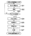
操作部23の図示しないモードスイッチを操作することにより全焦点画像撮影モードが設定され、さらに操作部23のシャッタースイッチが押されると、CPU24はこれらの操作に基づいて、焦点位置を設定し(ステップS21)、撮影を行う(ステップS22)。次に撮影した回数の判定を行う(ステップS23)。所定回数に満たない場合は、異なる焦点位置に設定し(ステップS21)、さらに撮影を行う(ステップS22)。このように異なる焦点位置での撮影を繰り返し、所定回数の撮影を行う(フォーカスブラケット撮影)。各撮影画像は、メインメモリ28のRAM領域に格納される。
When an omnifocal image capturing mode is set by operating a mode switch (not shown) of the
ここで、所定回数については、デジタルカメラ1内において予め定められた回数でもよいし、ユーザが設定できるようにしてもよい。また、撮影条件で決まる被写界深度を判断し、この被写界深度に応じて決定してもよい。全焦点画像を得るためには、画像内の全ての被写体において、いずれか1枚の画像においては合焦していることが必要である。よって、被写界深度が浅い場合は焦点位置の移動量を少なくして撮影枚数を多くする必要がある。また被写界深度が深い場合は焦点位置の移動量を多くして撮影枚数を少なくすることにより、無駄に多くの枚数を撮影してメモリを消費したり、処理負荷を増やすことを防止することができる。
Here, the predetermined number of times may be a predetermined number in the
また、この焦点位置の移動については、焦点位置が近い位置から遠い位置へ移動しても、遠い位置から近い位置へ移動しても、又はランダムに移動してもよい。 Further, regarding the movement of the focal position , the focal position may be moved from a position close to a far position, may be moved from a distant position to a close position, or may be moved randomly.
所定回数の撮影が終了すると、各撮影画像における対応点の検出を行う(ステップS24)。 When the predetermined number of times of shooting is completed, corresponding points in each shot image are detected (step S24).
ここで、画像内の対応点の検出について説明する。対応点検出は、複数画像間で対応する点の位置関係を求めるものである。図3は、フォーカスブラケット撮影から得られた画像を示す図である。対応点検出部36が、図3(a)に示す基準画像から特徴点を抽出し、その特徴点が図3(b)に示す追跡画像のどの位置に移動したかを追跡することにより、対応点の検出を行う。図4は、デジタルカメラ1の対応点検出の動作について示すフローチャートである。
Here, detection of corresponding points in the image will be described. Corresponding point detection is to obtain the positional relationship of corresponding points between a plurality of images. FIG. 3 is a diagram illustrating an image obtained from the focus bracket shooting. Corresponding
まず、CPU24は、対応点検出部36へフォーカスブラケット撮影を行った複数画像を入力する(ステップS41)。次に、対応点検出部36は、この複数画像の中から基準画像を選択し(ステップS42)、この基準画像から特徴点の抽出を行う(ステップS43)。基準画像の選択については、デジタルカメラ1内において予め定められた方法に基づいて選択してもよいし、ユーザが選択してもよい。ここでは、最初に撮影した画像を基準画像とする。特徴点抽出の手法は種々のものが提案されているが、ここでは、ある点を中心とする所定領域内の輝度の標準偏差が所定値以上の場合に、その点を特徴点として抽出する。図3(a)における丸印が、図3(a)の画像における特徴点を示す。特徴点は多いほうが以後の処理を精度よく行うことができるが、特徴点が多くなると処理負荷が増大するため、特徴点の数はハード性能から適宜決めればよい。
First, CPU 2 4 inputs a plurality image subjected to focus bracketing the corresponding point detection unit 36 (step S41). Next, the corresponding
次に、追跡画像の選択を行う(ステップS44)。ステップS41で入力された複数画像のうち、基準画像以外の画像を選択する。 Next, a tracking image is selected (step S44). Of the plurality of images input in step S41, an image other than the reference image is selected.
選択した追跡画像において、基準画像から抽出された特徴点の1つを選択し(ステップS45)、この特徴点ががどの位置へ移動したかを追跡する(ステップS46)。追跡手法についても種々のものが提案されているが、ここではその点を中心とする所定領域内の相互相関係数が最小となるような座標を見つける手法(ブロックマッチング法)を用いて追跡を行う。なお、本発明ではフォーカスブラケット撮影を行っているので、焦点位置が移動することによって対応点が移動する方向、及び移動する量は予測可能である。焦点位置の移動による対応点の移動は、画面中心から放射方向へ、又はその逆方向への移動であり、これは焦点位置の移動方向から予測可能である。またその移動量も焦点位置の移動量から予測可能である。よって、これらを考慮して対応点を検出することで、精度、速度ともに対応点検出性能を向上させることができる。 In the selected tracking image, one of the feature points extracted from the reference image is selected (step S45), and the position to which the feature point has moved is tracked (step S46). Various tracking methods have also been proposed. Here, tracking is performed using a method (block matching method) that finds coordinates that minimize the cross-correlation coefficient within a predetermined area centered on that point. Do. Since focus bracket photography is performed in the present invention, the direction and amount of movement of the corresponding point as the focal position moves can be predicted. The movement of the corresponding point by the movement of the focal position is a movement from the center of the screen in the radial direction or in the opposite direction, and this can be predicted from the movement direction of the focal position. The amount of movement can also be predicted from the amount of movement of the focal position. Therefore, by detecting the corresponding points in consideration of these, the corresponding point detection performance can be improved in both accuracy and speed.
特徴点の追跡が終了すると、全特徴点に対して処理を行ったか否かの判定を行う(ステップS47)。処理を行っていない特徴点がある場合は、その特徴点を選択し(ステップS45)、追跡を行う(ステップS46)。このように全ての特徴点において、追跡を行う。 When the tracking of feature points is completed, it is determined whether or not processing has been performed for all feature points (step S47). If there is a feature point that has not been processed, the feature point is selected (step S45), and tracking is performed (step S46). In this way, tracking is performed for all feature points.
全ての特徴点に対して処理を行うと、次に全ての追跡画像に対してこの処理を行ったか否かの判定を行う(ステップS48)。前述したように、この処理は基準画像以外の画像について行う。処理を行っていない追跡画像がある場合は、その追跡画像において同様の処理を行う。全ての追跡画像に対して処理が終了すると、対応点検出処理が終了する。 Once processing has been performed for all feature points, it is next determined whether or not this processing has been performed for all tracking images (step S4 8 ). As described above, this process is performed for images other than the reference image. If there is a tracking image that has not been processed, the same processing is performed on the tracking image. When the process is finished for all the tracking images, the corresponding point detection process is finished.
対応点検出処理が終了すると、次に画像変形を行う(ステップS25)。この画像変形処理は、対応点検出処理で得られた各追跡画像の対応点が基準画像の対応点の位置に極力一致するように、画像変形部37が追跡画像を変形する。図5は、画像変形について示す図である。図5(a)に示す基準画像に対して、図5(b)に示すように各対応点が平行移動している場合は、平行移動を行う。また図5(c)に示すように各対応点が回転移動移動している場合は、回転移動を行う。また図5(d)に示すように各対応点が拡大(縮小)している場合は、縮小(拡大)を行う。これらの画像変形は、複数組の対応点の距離の総和が最小となるように移動ベクトルを決めればよい。なお、これらの平行移動、回転、及び拡大・縮小処理は、アフィン変換により行う。
When the corresponding point detection process is completed, the image is then deformed (step S25). In this image deformation process, the
また図5(e)に示すように基準画像と追跡画像との間に複雑な動きが生じている場合は、全ての対応点をより精度よく一致させるためにはワーピングを行う。ワーピングは全ての対応点の組を完全に一致するような移動ベクトルを選択するとともに、その周囲の点も補間により求めるものである。 Further, as shown in FIG. 5E, when a complicated movement occurs between the reference image and the tracking image, warping is performed in order to match all corresponding points more accurately. In the warping, a movement vector that completely matches a set of all corresponding points is selected, and surrounding points are also obtained by interpolation.
このように対応点の位置を極力一致させた複数画像に対して、画像合成を行う(ステップS26)。図6は、画像合成処理の動作を示すフローチャートである。画像合成処理では、複数画像において最も鮮鋭度が高い画像、即ち最も焦点の合った画像の画素値を選択し、合成することにより、最終画像として画面内のどの位置においても鮮鋭度が高い画像、即ち全焦点画像を得る。 In this way, image synthesis is performed on a plurality of images in which the positions of corresponding points are matched as much as possible (step S26). FIG. 6 is a flowchart showing the operation of the image composition process. In the image composition process, an image having the highest sharpness in a plurality of images, that is, an image having a high sharpness at any position in the screen as a final image by selecting and synthesizing the pixel values of the most focused image, That is, an omnifocal image is obtained.
まず、画像合成部38が、処理を行う画素の選択を行う(ステップS61)。この画素の選択の順序については、画面の端から順に行えばよく、また他の順序でも構わない。次に、画像の選択を行い(ステップS62)、選択した画像における、ステップS61で選択された画素の鮮鋭度を算出する(ステップS63)。
First, the
鮮鋭度の算出については、ラプラシアンフィルタ処理による出力値の絶対値を算出することにより行う。図7は、ラプラシアンフィルタのフィルタ行列を示す図である。ラプラシアンフィルタ処理を行うことによりエッジ検出をすることができ、この出力値の絶対値が鮮鋭度を示す。画像のぼけと鮮鋭度に関しては、画像のぼけが小さい画素ほど鮮鋭度が高く、ぼけが大きくなるほど鮮鋭度が低くなるという関係がある。なお、ラプラシアンフィルタのカーネルはこの例に限定されるものではなく、またラプラシアンフィルタ以外の鮮鋭度算出フィルタを用いてもよい。 The sharpness is calculated by calculating the absolute value of the output value by Laplacian filter processing. FIG. 7 is a diagram illustrating a filter matrix of a Laplacian filter. Edge detection can be performed by performing Laplacian filter processing, and the absolute value of the output value indicates the sharpness. Regarding the blur and sharpness of an image, there is a relationship in which a pixel having a smaller blur of the image has a higher sharpness and a sharper the lower the blur is. The kernel of the Laplacian filter is not limited to this example, and a sharpness calculation filter other than the Laplacian filter may be used.
次に、全画像に対して鮮鋭度の算出が終了したか否かの判定を行う(ステップS64)。鮮鋭度の算出をしていない画像が有る場合には、再び画像の選択を行い(ステップS62)、選択した画像における、ステップS61で選択された画素の鮮鋭度を算出する(ステップS63)。このように、全画像に対して、ステップS61で選択された画素の鮮鋭度を算出する。 Next, it is determined whether or not the sharpness calculation has been completed for all images (step S64). If there is an image whose sharpness is not calculated, the image is selected again (step S62), and the sharpness of the pixel selected in step S61 in the selected image is calculated (step S63). In this way, the sharpness of the pixel selected in step S61 is calculated for all images.
次に、鮮鋭度が最大となる画像の画素値を出力する(ステップS65)。ステップS63において算出した、各画像のステップS61で選択した画素のラプラシアンフィルタ処理における出力値の絶対値を比較し、最大の値である画像の画素値を出力画素して採用する。また、鮮鋭度の高い画像の画素値に対する重みを大きくして加重平均を算出し、これを出力してもよい。 Next, the pixel value of the image with the maximum sharpness is output (step S65). The absolute value of the output value in the Laplacian filter processing of the pixel selected in step S61 of each image calculated in step S63 is compared, and the pixel value of the image that is the maximum value is used as the output pixel. Alternatively, the weighted average may be calculated by increasing the weight for the pixel value of the image with high sharpness, and this may be output.
以上の処理を全ての画素に対して行う。全画素に対して処理が行われたか否かを判定し、全画素に対して終了した場合は、画像合成処理が終了する。 The above processing is performed for all pixels. It is determined whether or not processing has been performed for all pixels, and when the processing has been completed for all pixels, the image composition processing ends.
画像合成処理が終了すると、CPU24は画像合成部38の出力画像をメモリ制御部32を介して記録媒体33に記録して、全焦点画像撮影が終了する(ステップS27)。
When the image composition process is completed, the
この画像合成部38の出力画像は、記録媒体33に保存せずに、表示制御部34を介して表示部35に表示するだけでもよいし、図示しない外部インターフェースを用いて、外部モニタに表示したり、プリンタ等に印刷物として出力してもよい。
The output image of the
このようにして、被写体ブレや手ブレがあっても、全焦点画像を得ることができる。 In this way, an omnifocal image can be obtained even when there is subject blur or camera shake.
特徴点の抽出方法や、特徴点の追跡方法、画像の変形方法、及び画素の鮮鋭度の算出方法については、本実施の形態の方法に限定されず、どの手法を用いても構わない。 The feature point extraction method, the feature point tracking method, the image deformation method, and the pixel sharpness calculation method are not limited to the method of the present embodiment, and any method may be used.
<第2の実施の形態>
次に、デジタルカメラ1におけるぼけ強調撮影について説明する。図8は、ぼけ強調画像を撮影するためのぼけ強調撮影モードの動作を示すフローチャートである。なお、図2のフローチャートと共通する部分には同一の符号を付し、その詳細な説明は省略する。
<Second Embodiment>
Next, blur enhanced shooting in the
本発明に係るデジタルカメラ1のぼけ強調画像撮影モードでは、オートフォーカスにより主要被写体の合焦位置とその前後の焦点位置での撮影を含むフォーカスブラケット撮影を行い、各撮影画像の対応点を検出し、対応点の位置が一致するように各撮影画像を変形し、変形した画像を合成することによりぼけ強調画像を得る。
In the blur-enhanced image shooting mode of the
まず操作部23のモードスイッチを操作することにより、ぼけ強調画像撮影モードに設定される。次に操作部23におけるシャッターボタンが押されると、まず主要被写体に対して自動合焦位置判断(AF)を行う(ステップS81)。このAFについては、通常撮影の際に行われるAFと同じものでよく、撮影に先立ってレンズの焦点位置を駆動させ、その都度積算部31でバンドパスフィルタの出力値等のAF評価値を算出し、CPUにて最もAF評価値の高い焦点位置を合焦位置と判断する。
First, the blur-enhanced image shooting mode is set by operating the mode switch of the
ぼけ強調画像撮影モードでのフォーカスブラケット撮影においては、主要被写体のAF合焦位置と主要被写体のAF合焦位置の前後の焦点位置を含むように焦点位置を移動させて撮影を行う。図9は、デジタルカメラ1の各焦点位置を横軸に、各焦点位置における主要被写体に対するAF評価値を縦軸に表したグラフである。最もAF評価値の高い焦点位置が主要被写体の合焦位置であり、この主要被写体の合焦位置をBとすると、本実施の形態のフォーカスブラケット撮影においては、合焦位置Bと、その前後に所定距離dだけ離れた焦点位置A及びCの3点を撮影の際の焦点位置とする。このdについては、予めデジタルカメラ1内に記憶された固定値でもよいし、ユーザが設定してもよい。また被写界深度を判断し、この被写界深度によって異ならせてもよい。被写界深度によりぼけの度合いが異なるため、被写界深度によりdの値を変更することにより、適切なぼけ具合の意図する画像を得ることが可能となる。
In focus bracket shooting in the blur-enhanced image shooting mode, shooting is performed by moving the focus position to include the AF focus position of the main subject and the focus positions before and after the AF focus position of the main subject. FIG. 9 is a graph in which each focal position of the
このように決められた焦点位置において、第1の実施の形態の全焦点画像撮影モードと同様に、フォーカスブラケット撮影を行う(ステップS21〜S23)。各撮影画像は、メインメモリ28のRAM領域に格納される。
At the focal position determined in this way, focus bracket shooting is performed in the same manner as in the omnifocal image shooting mode of the first embodiment (steps S21 to S23). Each captured image is stored in the RAM area of the
フォーカスブラケット撮影が終了すると、各撮影画像における対応点の検出を行う(ステップS24)。ここでは、基準画像を主要被写体の合焦位置Bで撮影された画像とする。対応点検出は第1の実施の形態と同様に行う。 When focus bracket photography is completed, corresponding points in each photographed image are detected (step S24). Here, it is assumed that the reference image is an image taken at the in-focus position B of the main subject. Corresponding point detection is performed in the same manner as in the first embodiment.
対応点検出処理が終了すると、次に画像変形を行う(ステップS25)。画像変形においても、第1の実施の形態と同様に行う。 When the corresponding point detection process is completed, the image is then deformed (step S25). The image deformation is performed in the same manner as in the first embodiment.
画像変形処理が終了すると、次に画像合成を行う。図10は第2の実施の形態における画像合成処理の動作のフローチャートである。なお、図6のフローチャートと共通する部分には同一の符号を付し、その詳細な説明は省略する。本発明の第2の実施の形態のデジタルカメラ1のぼけ強調画像撮影モードにおいては、画像合成処理において、複数画像において基準画像が最も鮮鋭度が高い場合は基準画像の画素を選択し、基準画像以外の画像が最も鮮鋭度が高い場合は、主要被写体の合焦位置に関して、画素の鮮鋭度が最大の焦点位置と対称となる焦点位置で撮影された画像の画素を選択することにより、ぼけ強調画像を得る。
When the image transformation process is completed, image composition is performed next. FIG. 10 is a flowchart of the operation of the image composition process in the second embodiment. In addition, the same code | symbol is attached | subjected to the part which is common in the flowchart of FIG. 6, and the detailed description is abbreviate | omitted. In the blur-enhanced image shooting mode of the
第1の実施の形態と同様に、画像合成部38は、処理を行う画素の選択を行い(ステップS61)、この選択された画素の各画像の鮮鋭度を算出する(ステップS62〜S64)。図11は、主要被写体の合焦位置Bで撮影された画像と、その合焦位置の前後の焦点位置であるA及びCで撮影された画像の、鮮鋭度の関係を示すグラフである。フォーカスブラケット撮影で3枚の画像を撮影した場合、このA、B、及びCの焦点位置で撮影された画像の鮮鋭度の関係は、図11(a)に示すCが最大の場合、図11(b)に示すBが最大の場合、及び図11(c)に示すAが最大の場合の3種類に分類することができる。
Similar to the first embodiment, the
全画像において選択された画素の鮮鋭度を算出すると、この算出された鮮鋭度に基づいて、基準画像の鮮鋭度が最大であるか否か、即ち鮮鋭度が図11(b)に示す関係であるか否かの判定を行う(ステップS101)。基準画像の鮮鋭度が最大の場合は、基準画像の画素値を出力する(ステップS102)。基準画像の鮮鋭度が最大でない場合は、主要被写体の合焦位置より遠い側の画像の鮮鋭度が最大であるか否か、即ち鮮鋭度が図11(a)に示す関係であるか否かの判定を行う(ステップS103)。主要被写体の合焦位置より遠い側の画像の鮮鋭度が最大の場合は、主要被写体の合焦位置より近い側の画像の画素値を出力する(ステップS104)。また逆に、主要被写体の合焦位置より遠い側の画像の鮮鋭度が最大でない場合は、主要被写体の合焦位置より近い側の画像の鮮鋭度が最大である、即ち鮮鋭度が図11(c)に示す関係であるので、主要被写体の合焦位置より遠い側の画像の画素値を出力する(ステップS105)。 When the sharpness of the selected pixel in all the images is calculated, based on the calculated sharpness, whether or not the sharpness of the reference image is the maximum, that is, the sharpness is in the relationship shown in FIG. It is determined whether or not there is (step S101). If the sharpness of the reference image is maximum, the pixel value of the reference image is output (step S102). When the sharpness of the reference image is not the maximum, whether the sharpness of the image farther from the in-focus position of the main subject is the maximum, that is, whether the sharpness has the relationship shown in FIG. Is determined (step S103). When the sharpness of the image farther from the focus position of the main subject is maximum, the pixel value of the image closer to the focus position of the main subject is output (step S104). On the contrary, when the sharpness of the image farther from the in-focus position of the main subject is not the maximum, the sharpness of the image closer to the in-focus position of the main subject is the maximum, that is, the sharpness is as shown in FIG. Because of the relationship shown in c), the pixel value of the image farther from the focus position of the main subject is output (step S105).
この処理を、全ての画素について行う。全画素に対して処理が終了したと判断すると(ステップS106)、画像合成処理が終了する。 This process is performed for all pixels. When it is determined that the processing has been completed for all the pixels (step S106), the image composition processing ends.
画像合成処理が終了すると、CPU24は画像合成部38の出力画像をメモリ制御部32を介して記録媒体33に記録して(ステップS27)、ぼけ強調画像撮影が終了する。
When the image composition processing is completed, the
このように、主要被写体の合焦位置Bで撮影された画像の鮮鋭度が低い画素の座標において、ぼけが強くなる画素値を選択することにより、ぼけ強調が可能となる。焦点位置が3点を超える場合でも、鮮鋭度の最大値を取る焦点位置と合焦位置を挟んで反対側の焦点位置にある複数画像から、ぼけ強調度合いに応じて選択すればよい。つまり、よりぼけを強調したい場合には、より鮮鋭度の低い画像の画素値を出力すればよい。 As described above, blur enhancement can be performed by selecting a pixel value at which blur is strong in the coordinates of a pixel having low sharpness in an image photographed at the in-focus position B of the main subject. Even when the focal position exceeds three points, selection may be made according to the degree of blur enhancement from a plurality of images at opposite focal positions across the focal position and the focal position where the maximum sharpness is obtained. That is, when it is desired to emphasize blur, it is only necessary to output pixel values of an image with lower sharpness.
なお、本実施の形態においては主要被写体の合焦位置と、合焦位置に対してdだけ離れたA及びCにおいてフォーカスブラケット撮影を行ったが、A及びCはBに対して対称でなく、dとd’のように合焦位置からの距離が異なってもよい。 In this embodiment, focus bracket shooting was performed at the in-focus position of the main subject and at A and C separated by d from the in-focus position. However, A and C are not symmetrical with respect to B. The distance from the in-focus position may be different as d and d ′.
また、本実施の形態の図10に示す画像合成処理は、対応点検出及び画像変形を行わない画像に対して行ってもよい。即ち、フォーカスブラケット撮影した複数画像において、直接この画像合成処理を行ってもよい。 Further, the image composition processing shown in FIG. 10 of the present embodiment may be performed on an image that is not subjected to corresponding point detection and image deformation. In other words, this image composition processing may be performed directly on a plurality of images taken with focus bracketing.
<第3の実施の形態>
本発明に係る第3の実施の形態のぼけ強調撮影について説明する。図12は、本発明に係る第3の実施の形態のデジタルカメラ1の内部構成の一例を示すブロック図である。図1に示すブロック図とは、画像合成部38の代わりにフィルタ処理部40を備えたところだけが異なる。
<Third Embodiment>
The blur-enhanced shooting according to the third embodiment of the present invention will be described. FIG. 12 is a block diagram showing an example of the internal configuration of the
図13は、デジタルカメラ1のぼけ強調撮影モードの動作を示すフローチャートである。なお、図2及び図8のフローチャートと共通する部分には同一の符号を付し、その詳細な説明は省略する。本発明の第3の実施の形態のデジタルカメラ1のぼけ強調画像撮影モードでは、オートフォーカスにより主要被写体の合焦位置とその前後の焦点位置での撮影を含むフォーカスブラケット撮影を行い、各撮影画像の対応点を検出し、対応点の位置が一致するように各撮影画像を変形し、変形した画像から各画素の鮮鋭度を算出し、鮮鋭度に基づいたフィルタ係数で基準画像にフィルタ処理を施すことによりぼけ強調画像を得る。
FIG. 13 is a flowchart showing the operation of the blur enhancement shooting mode of the
これまでと同様に、ぼけ強調撮影モードにおいて操作部23のシャッターボタンが押されると、主要被写体に対して自動合焦位置判断を行い(ステップS81)、次に焦点位置間隔dを決定する(ステップS161)。
As before, when the shutter button of the
本実施の形態では、フォーカスブラケット撮影の際に設定される焦点位置には、主要被写体の合焦位置と、その前後の焦点位置を含むようにする。ここでは図14に示すように、主要被写体の合焦位置F3、主要被写体の合焦位置から前後に焦点間隔dだけ離れた焦点位置F2及びF4、さらに主要被写体の合焦位置F3から遠ざかる方向に、焦点位置F2及びF4から焦点間隔dだけ離れた焦点位置のF1及びF5、の計5点をフォーカスブラケット撮影の際の焦点位置とする。なお、焦点位置の端から順に、F1で撮影された画像の番号を1、F2で撮影された画像の番号を2、・・・、F5で撮影された画像の番号を5、とする。 In the present embodiment, the focus position set at the time of focus bracket shooting includes the focus position of the main subject and the focus positions before and after the focus position. Here, as shown in FIG. 14, the focus position F3 of the main subject, the focus positions F2 and F4 that are separated from the focus position of the main subject by the focal interval d, and further away from the focus position F3 of the main subject. A total of five points, F1 and F5 at focal positions separated from the focal positions F2 and F4 by a focal distance d, are taken as focal positions for focus bracket photography. Note that in order from the end of the focal position, the number of the image captured at F1 is 1, the number of the image captured at F2 is 2,..., And the number of the image captured at F5 is 5.
図15は、撮影時の絞りと焦点距離、及びフォーカスブラケット撮影時の焦点位置の間隔dの関係を3次元的に示したグラフである。このように、絞りのF値が小さい場合や焦点距離が長い場合など、被写界深度が浅い場合はdを小さく、逆に絞りのF値が大きい場合や焦点距離が短い場合など、被写界深度が深い場合はdを大きくするように設定されている。CPU24は、メインメモリ28のROM領域に記憶されたこの設定に基づいて焦点間隔dを決定する。これにより、任意の絞りと焦点距離において、ぼけ強調に適した焦点の異なる画像を得ることができる。なお、焦点間隔dは一定でなくてもよく、例えば主要被写体の合焦位置から見てNEAR側とFAR側で変えるようにしてもよい。
FIG. 15 is a graph three-dimensionally showing the relationship between the aperture and focal length at the time of shooting and the distance d between the focal positions at the time of focus bracket shooting. Thus, when the depth of field is shallow, such as when the F value of the diaphragm is small or when the focal length is long, d is small, and conversely, when the F value of the diaphragm is large or the focal length is short, the object is captured. When the depth of field is deep, d is set to be large. The
以上のように撮影時の絞りと焦点距離から焦点間隔dを決定すると、次にF1〜F5の焦点位置において、フォーカスブラケット撮影を行う(ステップS21〜S23)。この撮影の順序に関しては、適宜決めてよい。各撮影画像は、メインメモリ28のRAM領域に格納される。
When the focal distance d is determined from the aperture and focal length at the time of photographing as described above, focus bracket photographing is performed at the focal positions F1 to F5 (steps S21 to S23). The order of shooting may be determined as appropriate. Each captured image is stored in the RAM area of the
フォーカスブラケット撮影が終了すると、主要被写体の合焦位置で撮影された画像を基準画像として、各撮影画像における対応点の検出を行う(ステップS24)。対応点の検出は、第一の実施の形態と同様に行う。対応点検出処理が終了すると、次に画像変形を行う(ステップS25)。 When focus bracket shooting is completed, the corresponding points in each captured image are detected using the image captured at the in-focus position of the main subject as a reference image (step S24). Corresponding points are detected in the same manner as in the first embodiment. When the corresponding point detection process is completed, the image is then deformed (step S25).
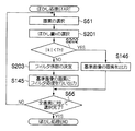
画像変形処理が終了すると、次にぼかし量算出を行う(ステップS162)。図16は、ぼかし量算出処理の動作を示すフローチャートである。なお、図6のフローチャートと共通する部分には同一の符号を付し、その詳細な説明は省略する。 When the image transformation process is completed, the blur amount is calculated (step S162). FIG. 16 is a flowchart showing the operation of the blur amount calculation process. In addition, the same code | symbol is attached | subjected to the part which is common in the flowchart of FIG. 6, and the detailed description is abbreviate | omitted.
最初に、フィルタ処理部40が、処理を行う画素の選択を行う(ステップS61)。次に、画像の選択を行い(ステップS62)、選択した画像における、ステップS61で選択された画素の鮮鋭度を算出する(ステップS63)。鮮鋭度の算出においては、第1の実施の形態と同様に、ラプラシアンフィルタ処理における出力値の絶対値を算出することにより行う。全画像に対して、ステップS61で選択された画素の鮮鋭度を算出する。
First, the
全画像に対して鮮鋭度の算出が終了したと判断すると(ステップS64)、次に算出した鮮鋭度が最大である画像番号nを算出し(ステップS191)、ぼかし量kを算出する(ステップS192)。 When it is determined that the calculation of the sharpness has been completed for all the images (step S64), the next image number n having the maximum calculated sharpness is calculated (step S191), and the blurring amount k is calculated (step S192). ).
ここで、主要被写体の合焦位置で撮影された画像番号をcとすると、ぼかし量kは以下の式で表される。 Here, if the image number taken at the in-focus position of the main subject is c, the blur amount k is expressed by the following equation.
(数1)
k=u×(nーc)
ここで、uはユーザが指定したぼけ強調度合いであり、uが1.0よりも大きければ基準設定よりもぼけが強調され、uが1.0未満の場合は基準設定よりもぼけが緩和される画像となる。なお、ぼけ強調度合いuは、ユーザが操作部23を操作することにより設定が可能となっている。また、本実施の形態ではc=3である。
(Equation 1)
k = u × (nc)
Here, u is the degree of blur enhancement specified by the user. If u is larger than 1.0, the blur is emphasized more than the standard setting, and if u is less than 1.0, the blur is reduced more than the standard setting. Image. Note that the blur enhancement degree u can be set by the user operating the
このぼかし量kの算出を全ての画素について行う。全ての画素について終了したと判断すると(ステップS66)、ぼかし量算出処理が終了する。 This blur amount k is calculated for all pixels. If it is determined that all the pixels have been completed (step S66), the blurring amount calculation process ends.
ぼかし量算出処理が終了すると、次にぼかし処理を行う(ステップS163)。図17は、ぼかし処理の動作を示すフローチャートである。本実施の形態では、ぼかし処理にガウシアンフィルタを用いる。 When the blur amount calculation process ends, the blur process is performed (step S163). FIG. 17 is a flowchart showing the operation of the blurring process. In this embodiment, a Gaussian filter is used for the blurring process.
まずフィルタ処理部40が、画素の選択を行い(ステップS61)、選択した画素のぼかし量kを選択する。図16のステップS192で算出された各画素のぼかし量kは、メインメモリ28のRAM領域に記憶されており、これを読み出す。
First, the
次に、読み出したぼかし量の絶対値|k|と所定の閾値Thとの比較を行う(ステップS202)。所定の閾値Thの方が大きい場合は、この画素を合焦領域とみなして被写体の合焦位置F3で撮影した画素値を出力する(ステップS146)。ぼかし量の絶対値|k|の方が大きい場合は、この画素をぼけ強調すべき領域とみなしてフィルタ係数を決定する(ステップS203)。 Next, the absolute value | k | of the read blur amount is compared with a predetermined threshold Th (step S202). If the predetermined threshold Th is larger, this pixel is regarded as a focus area, and a pixel value photographed at the focus position F3 of the subject is output (step S146). If the absolute value | k | of the blurring amount is larger, this pixel is regarded as a region to be blurred and emphasized, and a filter coefficient is determined (step S203).
前述したように、本実施の形態では、このフィルタ処理にガウシアンフィルタを用いる。図18は、ぼかし量の絶対値|k|と、ガウシアンフィルタのσパラメータの関係を示したグラフである。図18に示すように、ぼかし量の絶対値|k|が所定の閾値Th以上のとき、ぼかし量の絶対値|k|と比例関係にあるガウシアンフィルタのσパラメータが求められ、このσパラメータに応じたガウシアンフィルタ係数f(x)を決定する。CPU24は、メインメモリ28のRAM領域に記憶されたこの関係に基づいてσパラメータを決定する。
As described above, in this embodiment, a Gaussian filter is used for this filter processing. FIG. 18 is a graph showing the relationship between the absolute value | k | of the blur amount and the σ parameter of the Gaussian filter. As shown in FIG. 18, when the absolute value | k | of the blur amount is equal to or greater than a predetermined threshold Th, a σ parameter of a Gaussian filter that is proportional to the absolute value | k | of the blur amount is obtained. A corresponding Gaussian filter coefficient f (x) is determined. The
図18(b)は、注目画素からの距離xとガウシアンフィルタのフィルタ係数f(x)の関係を示したグラフである。図18(b)に示すように、ガウシアンフィルタはσパラメータが大きいほど周辺画素の重みを大きくして加重平均をとる。よってぼかし量の絶対値|k|の大きさに応じてσパラメータを大きくすることにより、ぼかし量の絶対値|k|が大きいほど平滑化の度合いを大きくすることができる。 FIG. 18B is a graph showing the relationship between the distance x from the target pixel and the filter coefficient f (x) of the Gaussian filter. As shown in FIG. 18B, the Gaussian filter takes a weighted average by increasing the weight of surrounding pixels as the σ parameter increases. Therefore, by increasing the σ parameter in accordance with the magnitude of the absolute value | k | of the blur amount, the degree of smoothing can be increased as the absolute value | k | of the blur amount increases.
このように求められたσパラメータからフィルタ係数f(x)を算出するには、[数2]を用いて演算を行い、算出されたフィルタ係数の総和が1になるように正規化
を行う。
In order to calculate the filter coefficient f (x) from the σ parameter thus obtained, calculation is performed using [Equation 2], and normalization is performed so that the total sum of the calculated filter coefficients becomes 1.

デジタルフィルタの場合は注目画素を中心とした離散位置ごとにf(x)が決定される。例えば5タップフィルタの場合は、f(x)={0.1、0.2、0.4、0.2、0.1}などとなる。なお一般には画像の明るさが変動しないよう、各係数の総和が1.0になるように正規化される。またここでは1次元のフィルタ係数で表現しているが、このフィルタを水平方向と垂直方向に順に施すことにより2次元のフィルタ処理を行うことができる。 In the case of a digital filter, f (x) is determined for each discrete position centered on the target pixel. For example, in the case of a 5-tap filter, f (x) = {0.1, 0.2, 0.4, 0.2, 0.1}. In general, normalization is performed so that the sum of the coefficients is 1.0 so that the brightness of the image does not fluctuate. In addition, although it is expressed by a one-dimensional filter coefficient here, two-dimensional filter processing can be performed by sequentially applying this filter in the horizontal direction and the vertical direction.
このように、選択した画素について、ぼかし量に応じたフィルタ処理を行い、出力画素値を算出する(ステップS145)。この処理を全画素について行い、全画素に対して処理が終了したと判断すると(ステップS66)、ぼかし処理が終了する。このように、主要被写体の合焦位置Bで撮影された基準画像に対してフィルタ処理を行うことにより、より自然なぼけ強調が可能となる。 As described above, the selected pixel is subjected to the filtering process according to the blur amount, and the output pixel value is calculated (step S145). This process is performed for all pixels, and if it is determined that the process has been completed for all pixels (step S66), the blurring process is terminated. As described above, by performing the filtering process on the reference image captured at the in-focus position B of the main subject, more natural blur enhancement can be performed.
なお、このフィルタ処理に用いるフィルタはガウシアンフィルタに限られるものではなく、ローパスフィルタなら他のフィルタでも構わない。例えば絞りやレンズの特性に応じたぼけ形状を持ったフィルタを用いてもよい。 Note that the filter used for this filter processing is not limited to the Gaussian filter, and other filters may be used as long as they are low-pass filters. For example, a filter having a blur shape corresponding to the characteristics of the diaphragm or lens may be used.
ぼかし処理が終了すると、CPU24はフィルタ処理部40の出力画像をメモリ制御部32を介して記録媒体33に記録して(ステップS27)、ぼけ強調撮影が終了する。
When blurring processing is completed,
このようにして、ぼけ強調画像を得ることができる。 In this way, a blur-emphasized image can be obtained.
なお、本実施の形態の図16及び図17に示すぼかし処理は、対応点検出及び画像変形を行わない画像に対して行ってもよい。即ち、フォーカスブラケット撮影した複数画像において、直接このぼかし処理を行ってもよい。 Note that the blurring process shown in FIGS. 16 and 17 of the present embodiment may be performed on an image that is not subjected to corresponding point detection and image deformation. That is, this blurring process may be performed directly on a plurality of images taken with focus bracketing.
1…デジタルカメラ、11…撮影レンズ、12…絞り、13…Irカットフィルタ、14…光学ローパスフィルタ、15…固体撮像素子、23…操作部、24…CPU、25…アドレスバス、26…データバス、27…メインメモリ制御部、28…メインメモリ、32…メモリ制御部、33…記録媒体、36…対応点検出部、37…画像変形部、38…画像合成部、40…フィルタ処理部
DESCRIPTION OF
Claims (9)
予め定められた移動量で離散的に焦点位置を移動して順次画像を撮影することにより複数の画像を得るフォーカスブラケット撮影手段と、
前記移動する焦点位置が前記自動合焦位置判断手段により判断された前記主要被写体の合焦位置とその前後の焦点位置を含むように制御する焦点位置制御手段と、
前記主要被写体の合焦位置で撮影された画像及び前記主要被写体の合焦位置の前後の焦点位置で撮影された画像を含む前記フォーカスブラケット撮影手段により撮影された複数の画像間の対応する座標の画素の鮮鋭度を算出する鮮鋭度算出手段と、
前記鮮鋭度算出手段の算出結果に基づいて、画素の座標に応じたぼかし量を算出するぼかし量算出手段と、
前記主要被写体の合焦位置で撮影された画像に対して、前記算出されたぼかし量に基づいてぼかし処理を行うぼかし処理手段と、
前記ぼかし処理手段によりぼかし処理された画像を記録媒体に記録する記録手段と、
を備えたことを特徴とする撮像装置。 Automatic focus position determination means for determining the focus position of the main subject based on the image data;
Focus bracket photographing means for obtaining a plurality of images by moving the focal position discretely with a predetermined amount of movement and sequentially photographing images;
Focus position control means for controlling the moving focus position to include the focus position of the main subject determined by the automatic focus position determination means and the focus positions before and after the focus position;
Corresponding coordinates between a plurality of images photographed by the focus bracket photographing means including an image photographed at a focus position of the main subject and an image photographed at a focal position before and after the focus position of the main subject. Sharpness calculation means for calculating the sharpness of the pixel;
Based on the calculation result of the sharpness calculation unit, a blur amount calculation unit that calculates a blur amount according to the coordinates of the pixel;
Blur processing means for performing blur processing based on the calculated blur amount on an image photographed at the in-focus position of the main subject ;
And recording means for recording the images, which are blurring by the blurring processing unit,
An imaging apparatus comprising:
前記主要被写体の合焦位置の前後の焦点位置で撮影された画像内の前記特徴点に対応する被写体の対応点を検出する対応点検出手段と、 Corresponding point detecting means for detecting corresponding points of the subject corresponding to the feature points in the image taken at the focal position before and after the in-focus position of the main subject;
前記対応点の座標がそれぞれ対応する前記特徴点の座標に一致するように前記主要被写体の合焦位置の前後の焦点位置で撮影された画像を変形する画像変形手段と、 Image deformation means for deforming an image photographed at a focal position before and after the in-focus position of the main subject so that the coordinates of the corresponding points coincide with the coordinates of the corresponding feature points, respectively.
を備え、 With
前記鮮鋭度算出手段は、前記主要被写体の合焦位置で撮影された画像及び前記変形された主要被写体の合焦位置の前後の焦点位置で撮影された画像の複数の画像間の対応する座標の画素の鮮鋭度を算出することを特徴とする請求項1に記載の撮像装置。 The sharpness calculation means is configured to calculate corresponding coordinates between a plurality of images of an image photographed at a focus position of the main subject and an image photographed at a focal position before and after the focus position of the deformed main subject. The imaging device according to claim 1, wherein the sharpness of the pixel is calculated.
前記ぼかし量算出手段は、最も鮮鋭度が大きい画像の焦点位置と前記主要被写体の合焦位置で撮影された画像の焦点位置の差が大きいほどぼかし量を大きくするように、前記ぼかし量を算出することを特徴とする請求項1から5のいずれかに記載の撮像装置。 The focal position control means controls to include a plurality of focal positions before the focusing position of the main subject, and / or controls to include a plurality of focal positions after the main subject,
The blur amount calculating means calculates the blur amount so that the blur amount increases as the difference between the focus position of the image with the highest sharpness and the focus position of the image captured at the focus position of the main subject increases. The imaging apparatus according to claim 1, wherein:
前記複数の画像間の対応する座標の画素の鮮鋭度を算出する鮮鋭度算出手段と、
前記鮮鋭度算出手段の算出結果に基づいて、画素の座標に応じたぼかし量を算出するぼかし量算出手段と、
前記主要被写体の合焦位置で撮影された画像に対して、前記算出されたぼかし量に基づいてぼかし処理を行うぼかし処理手段と、
前記ぼかし処理手段によりぼかし処理された画像を出力する出力手段と、
を備えたことを特徴とする画像処理装置。 Input means for inputting a plurality of images of the same scene captured at different focal positions, including an image captured at the focus position of the main subject and images captured at focal positions before and after the focus position of the main subject. When,
Sharpness calculation means for calculating the sharpness of pixels of corresponding coordinates between the plurality of images;
Based on the calculation result of the sharpness calculation unit, a blur amount calculation unit that calculates a blur amount according to the coordinates of the pixel;
Blur processing means for performing blur processing based on the calculated blur amount on an image photographed at the in-focus position of the main subject ;
And output means for outputting the images that are blurring by the blurring processing unit,
An image processing apparatus comprising:
予め定められた移動量で離散的に焦点位置を移動して順次画像を撮影することにより複数の画像を得るフォーカスブラケット撮影工程と、
前記移動する焦点位置が前記自動合焦位置判断工程により判断された前記主要被写体の合焦位置とその前後の焦点位置を含むように制御する焦点位置制御工程と、
前記主要被写体の合焦位置で撮影された画像及び前記主要被写体の合焦位置の前後の焦点位置で撮影された画像を含む前記フォーカスブラケット撮影工程により撮影された複数の画像間の対応する座標の画素の鮮鋭度を算出する鮮鋭度算出工程と、
前記鮮鋭度算出工程の算出結果に基づいて、画素の座標に応じたぼかし量を算出するぼかし量算出工程と、
前記主要被写体の合焦位置で撮影された画像に対して、前記算出されたぼかし量に基づいてぼかし処理を行うぼかし処理工程と、
前記ぼかし処理工程によりぼかし処理された画像を記録媒体に記録する記録工程と、
を備えたことを特徴とする撮像方法。 An automatic in-focus position determining step for determining the in-focus position of the main subject based on the image data;
A focus bracket photographing step of obtaining a plurality of images by moving the focal position discretely by a predetermined amount of movement and sequentially photographing images;
A focus position control step for controlling the moving focus position to include the focus position of the main subject determined by the automatic focus position determination step and the focus positions before and after the focus position;
Corresponding coordinates between a plurality of images photographed by the focus bracket photographing process including an image photographed at a focus position of the main subject and an image photographed at a focal position before and after the focus position of the main subject. A sharpness calculation step for calculating the sharpness of the pixel;
Based on the calculation result of the sharpness calculation step, a blur amount calculation step for calculating a blur amount according to the coordinates of the pixel;
A blurring process for performing blurring on the image captured at the in-focus position of the main subject , based on the calculated blurring amount;
A recording step of recording images which are blurring by the blurring process on the recording medium,
An imaging method comprising:
画像データに基づいて主要被写体の合焦位置を判断する自動合焦位置判断工程と、
予め定められた移動量で離散的に焦点位置を移動して順次画像を撮影することにより複数の画像を得るフォーカスブラケット撮影工程と、
前記移動する焦点位置が前記自動合焦位置判断工程により判断された前記主要被写体の合焦位置とその前後の焦点位置を含むように制御する焦点位置制御工程と、
前記主要被写体の合焦位置で撮影された画像及び前記主要被写体の合焦位置の前後の焦点位置で撮影された画像を含む前記フォーカスブラケット撮影工程により撮影された複数の画像間の対応する座標の画素の鮮鋭度を算出する鮮鋭度算出工程と、
前記鮮鋭度算出工程の算出結果に基づいて、画素の座標に応じたぼかし量を算出するぼかし量算出工程と、
前記主要被写体の合焦位置で撮影された画像に対して、前記算出されたぼかし量に基づいてぼかし処理を行うぼかし処理工程と、
前記ぼかし処理工程によりぼかし処理された画像を記録媒体に記録する記録工程と、
を備えたことを特徴とする画像処理方法。 An input step of inputting a plurality of images of the same scene captured at different focal positions, including an image captured at the focus position of the main subject and images captured at focal positions before and after the focus position of the main subject. When,
An automatic in-focus position determining step for determining the in-focus position of the main subject based on the image data;
A focus bracket photographing step of obtaining a plurality of images by moving the focal position discretely by a predetermined amount of movement and sequentially photographing images;
A focus position control step for controlling the moving focus position to include the focus position of the main subject determined by the automatic focus position determination step and the focus positions before and after the focus position;
Corresponding coordinates between a plurality of images photographed by the focus bracket photographing process including an image photographed at a focus position of the main subject and an image photographed at a focal position before and after the focus position of the main subject. A sharpness calculation step for calculating the sharpness of the pixel;
Based on the calculation result of the sharpness calculation step, a blur amount calculation step for calculating a blur amount according to the coordinates of the pixel;
A blurring process for performing blurring on the image captured at the in-focus position of the main subject , based on the calculated blurring amount;
A recording step of recording images which are blurring by the blurring process on the recording medium,
An image processing method comprising:
Priority Applications (2)
| Application Number | Priority Date | Filing Date | Title |
|---|---|---|---|
| JP2007112147A JP4582423B2 (en) | 2007-04-20 | 2007-04-20 | Imaging apparatus, image processing apparatus, imaging method, and image processing method |
| US12/105,813 US8184171B2 (en) | 2007-04-20 | 2008-04-18 | Image pickup apparatus, image processing apparatus, image pickup method, and image processing method |
Applications Claiming Priority (1)
| Application Number | Priority Date | Filing Date | Title |
|---|---|---|---|
| JP2007112147A JP4582423B2 (en) | 2007-04-20 | 2007-04-20 | Imaging apparatus, image processing apparatus, imaging method, and image processing method |
Related Child Applications (1)
| Application Number | Title | Priority Date | Filing Date |
|---|---|---|---|
| JP2010160850A Division JP5144724B2 (en) | 2010-07-15 | 2010-07-15 | Imaging apparatus, image processing apparatus, imaging method, and image processing method |
Publications (3)
| Publication Number | Publication Date |
|---|---|
| JP2008271241A JP2008271241A (en) | 2008-11-06 |
| JP2008271241A5 JP2008271241A5 (en) | 2010-05-27 |
| JP4582423B2 true JP4582423B2 (en) | 2010-11-17 |
Family
ID=39871784
Family Applications (1)
| Application Number | Title | Priority Date | Filing Date |
|---|---|---|---|
| JP2007112147A Expired - Fee Related JP4582423B2 (en) | 2007-04-20 | 2007-04-20 | Imaging apparatus, image processing apparatus, imaging method, and image processing method |
Country Status (2)
| Country | Link |
|---|---|
| US (1) | US8184171B2 (en) |
| JP (1) | JP4582423B2 (en) |
Families Citing this family (51)
| Publication number | Priority date | Publication date | Assignee | Title |
|---|---|---|---|---|
| US7813633B2 (en) * | 2007-07-31 | 2010-10-12 | Ricoh Company, Ltd. | Imaging device and imaging method |
| JP4763027B2 (en) * | 2008-08-27 | 2011-08-31 | シャープ株式会社 | Image processing apparatus, image forming apparatus, image processing method, image processing program, and computer-readable recording medium |
| JP4763026B2 (en) * | 2008-08-27 | 2011-08-31 | シャープ株式会社 | Image processing apparatus, image forming apparatus, image processing method, image processing program, and computer-readable recording medium |
| JP5282533B2 (en) * | 2008-11-12 | 2013-09-04 | 株式会社ニコン | Image processing apparatus, imaging apparatus, and program |
| JP2010122301A (en) * | 2008-11-17 | 2010-06-03 | Hitachi Ltd | Focus control device and focus control method |
| JP5267149B2 (en) * | 2009-01-19 | 2013-08-21 | ソニー株式会社 | Display control apparatus, display control method, and program |
| JP5206494B2 (en) * | 2009-02-27 | 2013-06-12 | 株式会社リコー | Imaging device, image display device, imaging method, image display method, and focus area frame position correction method |
| JP5226600B2 (en) * | 2009-04-28 | 2013-07-03 | 富士フイルム株式会社 | Image deformation apparatus and operation control method thereof |
| JP5460173B2 (en) | 2009-08-13 | 2014-04-02 | 富士フイルム株式会社 | Image processing method, image processing apparatus, image processing program, and imaging apparatus |
| US8558923B2 (en) * | 2010-05-03 | 2013-10-15 | Canon Kabushiki Kaisha | Image capturing apparatus and method for selective real time focus/parameter adjustment |
| WO2012001947A1 (en) * | 2010-06-28 | 2012-01-05 | 株式会社ニコン | Imaging device, image processing device, image processing program recording medium |
| EP2410377A1 (en) * | 2010-07-20 | 2012-01-25 | Research In Motion Limited | Method for decreasing depth of field of a camera having fixed aperture |
| US20120019688A1 (en) * | 2010-07-20 | 2012-01-26 | Research In Motion Limited | Method for decreasing depth of field of a camera having fixed aperture |
| JP2012027408A (en) * | 2010-07-27 | 2012-02-09 | Sanyo Electric Co Ltd | Electronic equipment |
| US9485495B2 (en) * | 2010-08-09 | 2016-11-01 | Qualcomm Incorporated | Autofocus for stereo images |
| JPWO2012073779A1 (en) * | 2010-12-01 | 2014-05-19 | Necカシオモバイルコミュニケーションズ株式会社 | Portable terminal, image processing method and program |
| CN102158648B (en) * | 2011-01-27 | 2014-09-10 | 明基电通有限公司 | Image capturing device and image processing method |
| WO2012108099A1 (en) | 2011-02-09 | 2012-08-16 | 富士フイルム株式会社 | Imaging device and imaging method |
| JP5484631B2 (en) * | 2011-03-31 | 2014-05-07 | 富士フイルム株式会社 | Imaging apparatus, imaging method, program, and program storage medium |
| JP5640143B2 (en) | 2011-03-31 | 2014-12-10 | 富士フイルム株式会社 | Imaging apparatus and imaging method |
| CN103348667A (en) * | 2011-03-31 | 2013-10-09 | 富士胶片株式会社 | Image-capturing device, image-capturing method, and program |
| US9438889B2 (en) | 2011-09-21 | 2016-09-06 | Qualcomm Incorporated | System and method for improving methods of manufacturing stereoscopic image sensors |
| JP5554453B2 (en) * | 2011-09-30 | 2014-07-23 | 富士フイルム株式会社 | Image processing apparatus and method |
| JP5971954B2 (en) * | 2012-01-12 | 2016-08-17 | キヤノン株式会社 | Image processing apparatus, imaging apparatus having image processing apparatus, image processing method, program, and storage medium storing program |
| JP2013258577A (en) * | 2012-06-13 | 2013-12-26 | Canon Inc | Imaging device, imaging method and program, image encoding device, and image encoding method and program |
| US20130342735A1 (en) * | 2012-06-20 | 2013-12-26 | Chen-Hung Chan | Image processing method and image processing apparatus for performing defocus operation according to image alignment related information |
| JP6074926B2 (en) * | 2012-07-05 | 2017-02-08 | カシオ計算機株式会社 | Image processing apparatus, image processing method, and program |
| US9398264B2 (en) | 2012-10-19 | 2016-07-19 | Qualcomm Incorporated | Multi-camera system using folded optics |
| US9894269B2 (en) | 2012-10-31 | 2018-02-13 | Atheer, Inc. | Method and apparatus for background subtraction using focus differences |
| US20140125831A1 (en) * | 2012-11-06 | 2014-05-08 | Mediatek Inc. | Electronic device and related method and machine readable storage medium |
| JP6152772B2 (en) * | 2012-11-29 | 2017-06-28 | パナソニックIpマネジメント株式会社 | Imaging apparatus, semiconductor integrated circuit, and imaging method |
| KR102022892B1 (en) * | 2013-01-23 | 2019-11-04 | 삼성전자 주식회사 | Apparatus and method for processing image of mobile terminal comprising camera |
| JP2015012304A (en) * | 2013-06-26 | 2015-01-19 | ソニー株式会社 | Image processing apparatus, image processing method, and program |
| US20150033157A1 (en) * | 2013-07-25 | 2015-01-29 | Mediatek Inc. | 3d displaying apparatus and the method thereof |
| US10178373B2 (en) | 2013-08-16 | 2019-01-08 | Qualcomm Incorporated | Stereo yaw correction using autofocus feedback |
| JP6351255B2 (en) * | 2013-12-19 | 2018-07-04 | キヤノン株式会社 | Imaging apparatus, imaging method, program, and storage medium |
| US9383550B2 (en) | 2014-04-04 | 2016-07-05 | Qualcomm Incorporated | Auto-focus in low-profile folded optics multi-camera system |
| US9374516B2 (en) | 2014-04-04 | 2016-06-21 | Qualcomm Incorporated | Auto-focus in low-profile folded optics multi-camera system |
| US10013764B2 (en) | 2014-06-19 | 2018-07-03 | Qualcomm Incorporated | Local adaptive histogram equalization |
| US9294672B2 (en) | 2014-06-20 | 2016-03-22 | Qualcomm Incorporated | Multi-camera system using folded optics free from parallax and tilt artifacts |
| US9386222B2 (en) | 2014-06-20 | 2016-07-05 | Qualcomm Incorporated | Multi-camera system using folded optics free from parallax artifacts |
| US9819863B2 (en) | 2014-06-20 | 2017-11-14 | Qualcomm Incorporated | Wide field of view array camera for hemispheric and spherical imaging |
| US9541740B2 (en) | 2014-06-20 | 2017-01-10 | Qualcomm Incorporated | Folded optic array camera using refractive prisms |
| US9549107B2 (en) | 2014-06-20 | 2017-01-17 | Qualcomm Incorporated | Autofocus for folded optic array cameras |
| JP6478496B2 (en) * | 2014-07-03 | 2019-03-06 | キヤノン株式会社 | Imaging apparatus and control method thereof |
| US9832381B2 (en) | 2014-10-31 | 2017-11-28 | Qualcomm Incorporated | Optical image stabilization for thin cameras |
| US9804392B2 (en) | 2014-11-20 | 2017-10-31 | Atheer, Inc. | Method and apparatus for delivering and controlling multi-feed data |
| EP3441812B1 (en) * | 2017-08-11 | 2020-07-01 | Tecan Trading Ag | Pattern based autofocus method for a microscopy |
| JP6590894B2 (en) * | 2017-11-08 | 2019-10-16 | キヤノン株式会社 | Image processing apparatus, imaging apparatus, image processing method, and program |
| JP7195790B2 (en) * | 2018-07-02 | 2022-12-26 | キヤノン株式会社 | Imaging device and its control method |
| DE102019201467B4 (en) | 2019-02-05 | 2023-03-02 | Carl Zeiss Ag | Method for operating a camera system and camera system |
Citations (7)
| Publication number | Priority date | Publication date | Assignee | Title |
|---|---|---|---|---|
| JPH0380676A (en) * | 1989-08-23 | 1991-04-05 | Ricoh Co Ltd | Electronic pan focus device |
| JP2001298657A (en) * | 2000-04-17 | 2001-10-26 | Teiichi Okochi | Image forming method and image forming device |
| JP2002084444A (en) * | 2000-09-06 | 2002-03-22 | Minolta Co Ltd | Image pickup device |
| JP2003051979A (en) * | 2001-08-03 | 2003-02-21 | Minolta Co Ltd | Electronic camera provided with image processing function and a computer-readable recording medium recording program enabling the electronic camera to realize the image processing function |
| JP2003283902A (en) * | 2002-03-26 | 2003-10-03 | Fuji Photo Film Co Ltd | Digital steel camera and image processor |
| JP2003289429A (en) * | 2002-03-28 | 2003-10-10 | Minolta Co Ltd | Program |
| JP2005159561A (en) * | 2003-11-21 | 2005-06-16 | Sharp Corp | Beautiful face camera |
Family Cites Families (10)
| Publication number | Priority date | Publication date | Assignee | Title |
|---|---|---|---|---|
| JP4612750B2 (en) | 1998-03-17 | 2011-01-12 | キヤノン株式会社 | Digital camera, photographing method, and storage medium |
| JP2002077591A (en) | 2000-09-05 | 2002-03-15 | Minolta Co Ltd | Image processing device and imaging device |
| SE518050C2 (en) * | 2000-12-22 | 2002-08-20 | Afsenius Sven Aake | Camera that combines sharply focused parts from various exposures to a final image |
| US7058233B2 (en) * | 2001-05-30 | 2006-06-06 | Mitutoyo Corporation | Systems and methods for constructing an image having an extended depth of field |
| JP3624859B2 (en) * | 2001-06-19 | 2005-03-02 | カシオ計算機株式会社 | Imaging device, soft focus image photographing method |
| US20030071909A1 (en) * | 2001-10-11 | 2003-04-17 | Peters Geoffrey W. | Generating images of objects at different focal lengths |
| JP4170194B2 (en) | 2003-10-28 | 2008-10-22 | 富士フイルム株式会社 | Imaging device |
| JP2006140594A (en) | 2004-11-10 | 2006-06-01 | Pentax Corp | Digital camera |
| US7653298B2 (en) * | 2005-03-03 | 2010-01-26 | Fujifilm Corporation | Image capturing apparatus, image capturing method, image capturing program, image recording output system and image recording output method |
| JP4878978B2 (en) | 2006-10-10 | 2012-02-15 | 三星電子株式会社 | Imaging apparatus and imaging method |
-
2007
- 2007-04-20 JP JP2007112147A patent/JP4582423B2/en not_active Expired - Fee Related
-
2008
- 2008-04-18 US US12/105,813 patent/US8184171B2/en active Active
Patent Citations (7)
| Publication number | Priority date | Publication date | Assignee | Title |
|---|---|---|---|---|
| JPH0380676A (en) * | 1989-08-23 | 1991-04-05 | Ricoh Co Ltd | Electronic pan focus device |
| JP2001298657A (en) * | 2000-04-17 | 2001-10-26 | Teiichi Okochi | Image forming method and image forming device |
| JP2002084444A (en) * | 2000-09-06 | 2002-03-22 | Minolta Co Ltd | Image pickup device |
| JP2003051979A (en) * | 2001-08-03 | 2003-02-21 | Minolta Co Ltd | Electronic camera provided with image processing function and a computer-readable recording medium recording program enabling the electronic camera to realize the image processing function |
| JP2003283902A (en) * | 2002-03-26 | 2003-10-03 | Fuji Photo Film Co Ltd | Digital steel camera and image processor |
| JP2003289429A (en) * | 2002-03-28 | 2003-10-10 | Minolta Co Ltd | Program |
| JP2005159561A (en) * | 2003-11-21 | 2005-06-16 | Sharp Corp | Beautiful face camera |
Also Published As
| Publication number | Publication date |
|---|---|
| US8184171B2 (en) | 2012-05-22 |
| JP2008271241A (en) | 2008-11-06 |
| US20080259172A1 (en) | 2008-10-23 |
Similar Documents
| Publication | Publication Date | Title |
|---|---|---|
| JP4582423B2 (en) | Imaging apparatus, image processing apparatus, imaging method, and image processing method | |
| JP4678603B2 (en) | Imaging apparatus and imaging method | |
| JP6271990B2 (en) | Image processing apparatus and image processing method | |
| US8629915B2 (en) | Digital photographing apparatus, method of controlling the same, and computer readable storage medium | |
| JP4665718B2 (en) | Imaging device | |
| US9489747B2 (en) | Image processing apparatus for performing object recognition focusing on object motion, and image processing method therefor | |
| JP5036599B2 (en) | Imaging device | |
| JP5831033B2 (en) | Imaging apparatus and distance information acquisition method | |
| JP5144724B2 (en) | Imaging apparatus, image processing apparatus, imaging method, and image processing method | |
| JP5453573B2 (en) | Imaging apparatus, imaging method, and program | |
| JP2013005091A (en) | Imaging apparatus and distance information acquisition method | |
| JP6223059B2 (en) | Imaging apparatus, control method thereof, and program | |
| KR101728042B1 (en) | Digital photographing apparatus and control method thereof | |
| JP5800187B2 (en) | Imaging apparatus and distance information acquisition method | |
| JP6391304B2 (en) | Imaging apparatus, control method, and program | |
| JP2009284056A (en) | Image processing apparatus, method, and program | |
| JP2007133301A (en) | Autofocus camera | |
| JP2016142999A (en) | Imaging device and control method of the same | |
| JP2011066827A (en) | Image processing apparatus, image processing method and program | |
| JP6486453B2 (en) | Image processing apparatus, image processing method, and program | |
| JP2016059051A (en) | Imaging device and distance information acquisition method | |
| JP2023033355A (en) | Image processing device and control method therefor | |
| JP2013042375A (en) | Image pickup device and distance information acquisition method | |
| JP2005208274A (en) | Autofocusing camera | |
| JP6223502B2 (en) | Image processing apparatus, image processing method, program, and storage medium storing the same |
Legal Events
| Date | Code | Title | Description |
|---|---|---|---|
| A521 | Request for written amendment filed |
Free format text: JAPANESE INTERMEDIATE CODE: A523 Effective date: 20100408 |
|
| A621 | Written request for application examination |
Free format text: JAPANESE INTERMEDIATE CODE: A621 Effective date: 20100408 |
|
| A871 | Explanation of circumstances concerning accelerated examination |
Free format text: JAPANESE INTERMEDIATE CODE: A871 Effective date: 20100408 |
|
| A975 | Report on accelerated examination |
Free format text: JAPANESE INTERMEDIATE CODE: A971005 Effective date: 20100426 |
|
| A131 | Notification of reasons for refusal |
Free format text: JAPANESE INTERMEDIATE CODE: A131 Effective date: 20100519 |
|
| A521 | Request for written amendment filed |
Free format text: JAPANESE INTERMEDIATE CODE: A523 Effective date: 20100715 |
|
| TRDD | Decision of grant or rejection written | ||
| A01 | Written decision to grant a patent or to grant a registration (utility model) |
Free format text: JAPANESE INTERMEDIATE CODE: A01 Effective date: 20100805 |
|
| A01 | Written decision to grant a patent or to grant a registration (utility model) |
Free format text: JAPANESE INTERMEDIATE CODE: A01 |
|
| A61 | First payment of annual fees (during grant procedure) |
Free format text: JAPANESE INTERMEDIATE CODE: A61 Effective date: 20100818 |
|
| R150 | Certificate of patent or registration of utility model |
Ref document number: 4582423 Country of ref document: JP Free format text: JAPANESE INTERMEDIATE CODE: R150 Free format text: JAPANESE INTERMEDIATE CODE: R150 |
|
| FPAY | Renewal fee payment (event date is renewal date of database) |
Free format text: PAYMENT UNTIL: 20130910 Year of fee payment: 3 |
|
| R250 | Receipt of annual fees |
Free format text: JAPANESE INTERMEDIATE CODE: R250 |
|
| R250 | Receipt of annual fees |
Free format text: JAPANESE INTERMEDIATE CODE: R250 |
|
| R250 | Receipt of annual fees |
Free format text: JAPANESE INTERMEDIATE CODE: R250 |
|
| R250 | Receipt of annual fees |
Free format text: JAPANESE INTERMEDIATE CODE: R250 |
|
| R250 | Receipt of annual fees |
Free format text: JAPANESE INTERMEDIATE CODE: R250 |
|
| R250 | Receipt of annual fees |
Free format text: JAPANESE INTERMEDIATE CODE: R250 |
|
| R250 | Receipt of annual fees |
Free format text: JAPANESE INTERMEDIATE CODE: R250 |
|
| R250 | Receipt of annual fees |
Free format text: JAPANESE INTERMEDIATE CODE: R250 |
|
| LAPS | Cancellation because of no payment of annual fees |