JP2014071207A - Image processing apparatus, imaging system, and image processing system - Google Patents
Image processing apparatus, imaging system, and image processing system Download PDFInfo
- Publication number
- JP2014071207A JP2014071207A JP2012216048A JP2012216048A JP2014071207A JP 2014071207 A JP2014071207 A JP 2014071207A JP 2012216048 A JP2012216048 A JP 2012216048A JP 2012216048 A JP2012216048 A JP 2012216048A JP 2014071207 A JP2014071207 A JP 2014071207A
- Authority
- JP
- Japan
- Prior art keywords
- image
- images
- observation
- depth
- processing apparatus
- Prior art date
- Legal status (The legal status is an assumption and is not a legal conclusion. Google has not performed a legal analysis and makes no representation as to the accuracy of the status listed.)
- Abandoned
Links
Images


Classifications
-
- G—PHYSICS
- G02—OPTICS
- G02B—OPTICAL ELEMENTS, SYSTEMS OR APPARATUS
- G02B21/00—Microscopes
- G02B21/36—Microscopes arranged for photographic purposes or projection purposes or digital imaging or video purposes including associated control and data processing arrangements
- G02B21/365—Control or image processing arrangements for digital or video microscopes
- G02B21/367—Control or image processing arrangements for digital or video microscopes providing an output produced by processing a plurality of individual source images, e.g. image tiling, montage, composite images, depth sectioning, image comparison
-
- G—PHYSICS
- G02—OPTICS
- G02B—OPTICAL ELEMENTS, SYSTEMS OR APPARATUS
- G02B21/00—Microscopes
- G02B21/36—Microscopes arranged for photographic purposes or projection purposes or digital imaging or video purposes including associated control and data processing arrangements
- G02B21/368—Microscopes arranged for photographic purposes or projection purposes or digital imaging or video purposes including associated control and data processing arrangements details of associated display arrangements, e.g. mounting of LCD monitor
-
- G—PHYSICS
- G06—COMPUTING; CALCULATING OR COUNTING
- G06T—IMAGE DATA PROCESSING OR GENERATION, IN GENERAL
- G06T1/00—General purpose image data processing
- G06T1/0007—Image acquisition
-
- H—ELECTRICITY
- H04—ELECTRIC COMMUNICATION TECHNIQUE
- H04N—PICTORIAL COMMUNICATION, e.g. TELEVISION
- H04N13/00—Stereoscopic video systems; Multi-view video systems; Details thereof
- H04N13/30—Image reproducers
- H04N13/388—Volumetric displays, i.e. systems where the image is built up from picture elements distributed through a volume
- H04N13/395—Volumetric displays, i.e. systems where the image is built up from picture elements distributed through a volume with depth sampling, i.e. the volume being constructed from a stack or sequence of 2D image planes
Landscapes
- Engineering & Computer Science (AREA)
- Physics & Mathematics (AREA)
- Multimedia (AREA)
- General Physics & Mathematics (AREA)
- Optics & Photonics (AREA)
- Chemical & Material Sciences (AREA)
- Analytical Chemistry (AREA)
- Computer Vision & Pattern Recognition (AREA)
- Theoretical Computer Science (AREA)
- Signal Processing (AREA)
- Microscoopes, Condenser (AREA)
- Image Processing (AREA)
- Studio Devices (AREA)
- Image Analysis (AREA)
Abstract
Description
本発明は、画像処理装置、撮像システム、および画像処理システムに関し、特に、デジタル画像による被写体観察を支援するための技術に関する。 The present invention relates to an image processing apparatus, an imaging system, and an image processing system, and more particularly to a technique for supporting subject observation using a digital image.
近年、病理分野において、病理診断のツールである光学顕微鏡の代替として、プレパラートに載置された被検試料の撮像と画像のデジタル化によってディスプレイ上での病理診断を可能とするバーチャル・スライド・システムが注目を集めている。バーチャル・スライド・システムを用いた病理診断画像のデジタル化により、従来の被検試料の光学顕微鏡像をデジタルデータとして取り扱うことが可能となる。その結果、遠隔診断の迅速化、デジタル画像を用いた患者への説明、希少症例の共有化、教育・実習の効率化、などのメリットが得られると期待されている。 In recent years, in the field of pathology, as an alternative to an optical microscope that is a tool for pathological diagnosis, a virtual slide system that enables pathological diagnosis on a display by imaging a test sample placed on a slide and digitizing the image Has attracted attention. By digitizing a pathological diagnosis image using a virtual slide system, a conventional optical microscope image of a test sample can be handled as digital data. As a result, it is expected that merits such as quick remote diagnosis, explanation to patients using digital images, sharing of rare cases, and efficiency of education / practice will be obtained.
光学顕微鏡と同等程度の操作をバーチャル・スライド・システムで実現するためには、プレパラート上の被検試料全体をデジタル化する必要がある。被検試料全体のデジタル化により、バーチャル・スライド・システムで作成したデジタルデータをPCやワークステーション上で動作するビューワソフトで観察することができる。被検試料全体をデジタル化した場合の画素数は、通常、数億画素から数十億画素と非常に大きなデータ量となる。 In order to realize an operation equivalent to that of an optical microscope with a virtual slide system, it is necessary to digitize the entire test sample on the slide. By digitizing the entire test sample, digital data created by the virtual slide system can be observed with viewer software operating on a PC or workstation. When the entire test sample is digitized, the number of pixels is usually a very large data amount of several hundred million to several billion pixels.
バーチャル・スライド・システムで作成したデータ量は膨大であるが、それゆえ、ビューワで拡大・縮小処理を行うことでミクロ(細部拡大像)からマクロ(全体俯瞰像)まで観察することが可能となり、種々の利便性を提供する。必要な情報を予めすべて取得しておくことで、低倍画像から高倍画像までユーザーが求める解像度・倍率による即時の表示が可能となる。 The amount of data created by the virtual slide system is enormous, so it is possible to observe from the micro (detailed magnified image) to the macro (overall bird's-eye view) by performing enlargement / reduction processing with the viewer. Provides various conveniences. By acquiring all necessary information in advance, it is possible to display immediately from the low-magnification image to the high-magnification image at the resolution and magnification required by the user.
様々な利便性を提供するバーチャル・スライド・システムであるが、従来の光学顕微鏡観察に対して使い勝手で及んでいない部分も依然として残っている。 Although it is a virtual slide system that provides various conveniences, there are still some parts that are not convenient for conventional optical microscope observation.
その1つが奥行き方向(光学顕微鏡の光軸に沿った方向あるいはプレパラートの観察面に垂直な方向)の観察である。通常、医師は光学顕微鏡で観察する際には、ステージを光軸方向に微動させてプレパラート上の検体内の焦点位置を変えて、組織や細胞の立体構造を把握する。バーチャル・スライド・システムで同様の操作を行う場合には、ある焦点位置での画像を撮像した後、焦点位置を変更し(例えば、プレパラートが置かれたステージを光軸方向に移動させ)再度画像を取得する必要がある。 One of them is observation in the depth direction (the direction along the optical axis of the optical microscope or the direction perpendicular to the observation surface of the slide). Usually, when observing with an optical microscope, a doctor moves the stage in the direction of the optical axis to change the focal position in the specimen on the preparation to grasp the three-dimensional structure of the tissue or cells. When performing the same operation in the virtual slide system, after taking an image at a certain focal position, the focal position is changed (for example, the stage on which the slide is placed is moved in the direction of the optical axis) and the image is again displayed. Need to get.
焦点位置を変えながら撮像を繰り返すことにより得られた複数枚の画像の取り扱い、表示の手法として以下の提案がされている。特許文献1では、焦点位置の異なる複数枚の画像をそれぞれ複数の部分領域に分割し、部分領域毎に深度合成を行うことにより、被写界深度の深いパンフォーカス画像を生成するシステムが開示されている。
The following proposals have been made as methods for handling and displaying a plurality of images obtained by repeating imaging while changing the focal position.
上述した特許文献1の方法によれば、画像全域について焦点の合った、ボケの少ない画
像が得られるため、1つの画像だけで被写体全体の様子を把握できるという利点がある。しかしながら、このようなパンフォーカス画像は、被写体全体を大まかに観察するのには有用であるものの、被写体の一部を詳細に観察したり、被写体の立体的な構造を把握したりする目的には適していない。多数の画像を深度合成したことにより、奥行き方向の情報(前後関係の情報)が失われてしまっているためである。
According to the method of
本発明はかかる問題に鑑みなされたものであり、デジタル画像を利用した被写体観察において、被写体の奥行き方向の詳細な観察を支援するための技術を提供することを目的とする。 The present invention has been made in view of such a problem, and an object of the present invention is to provide a technique for supporting detailed observation of a subject in the depth direction in subject observation using a digital image.
本発明の第1態様は、被写体の異なる位置を顕微鏡装置で撮像することにより得られた複数のレイヤー画像を取得する画像取得手段と、前記複数のレイヤー画像から複数の観察用画像を生成する画像生成手段と、前記観察用画像を表示装置に表示する画像表示手段と、を備え、前記画像生成手段は、前記複数のレイヤー画像のうちの2枚以上のレイヤー画像を深度合成することで1枚の観察用画像を生成する合成処理を複数回実行することによって前記複数の観察用画像を生成する画像処理装置である。 According to a first aspect of the present invention, there is provided an image acquisition means for acquiring a plurality of layer images obtained by imaging different positions of a subject with a microscope apparatus, and an image for generating a plurality of observation images from the plurality of layer images. Generating means and image display means for displaying the observation image on a display device, wherein the image generating means performs depth synthesis of two or more layer images of the plurality of layer images, This is an image processing device that generates the plurality of observation images by executing a synthesizing process for generating a plurality of observation images a plurality of times.
本発明の第2態様は、被写体の異なる位置を顕微鏡装置で撮像することにより複数のレイヤー画像を生成する撮像装置と、前記撮像装置から前記複数のレイヤー画像を取得する前記画像処理装置と、を備える撮像システムである。 According to a second aspect of the present invention, there is provided an imaging device that generates a plurality of layer images by imaging different positions of a subject with a microscope device, and the image processing device that acquires the plurality of layer images from the imaging device. An imaging system is provided.
本発明の第3態様は、被写体の異なる位置を顕微鏡装置で撮像することにより得られた複数のレイヤー画像を格納するサーバと、前記サーバから前記複数のレイヤー画像を取得する前記画像処理装置と、を備える画像処理システムである。 According to a third aspect of the present invention, a server that stores a plurality of layer images obtained by imaging different positions of a subject with a microscope device, the image processing device that acquires the plurality of layer images from the server, Is an image processing system.
本発明の第4態様は、被写体の異なる位置を顕微鏡装置で撮像することにより得られた複数のレイヤー画像を取得するステップと、前記複数のレイヤー画像から複数の観察用画像を生成するステップと、前記観察用画像を表示装置に表示するステップと、をコンピュータに実行させるためのプログラムであって、前記観察用画像を生成するステップでは、前記複数のレイヤー画像のうちの2枚以上のレイヤー画像を深度合成することで1枚の観察用画像を生成する合成処理を複数回実行することによって、前記複数の観察用画像が生成されるプログラムである。 According to a fourth aspect of the present invention, a step of acquiring a plurality of layer images obtained by imaging different positions of a subject with a microscope device, a step of generating a plurality of observation images from the plurality of layer images, A program for causing a computer to execute the step of displaying the image for observation on a display device, wherein the step of generating the image for observation includes two or more layer images of the plurality of layer images. This is a program in which a plurality of observation images are generated by executing a combination process of generating a single observation image by depth combination.
本発明によれば、デジタル画像を利用した被写体観察において、被写体の奥行き方向の詳細な観察を容易に行うことができる。 According to the present invention, detailed observation in the depth direction of a subject can be easily performed in subject observation using a digital image.
以下に本発明の実施の形態について図面を参照して説明する。 Embodiments of the present invention will be described below with reference to the drawings.
[第1の実施形態]
(システム構成)
図1は、本発明の第1の実施形態に係る撮像システムの装置構成の全体図である。
[First Embodiment]
(System configuration)
FIG. 1 is an overall view of an apparatus configuration of an imaging system according to the first embodiment of the present invention.
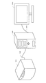
本実施形態における撮像システムは、撮像装置101、画像処理装置102、表示装置103から構成され、撮像対象となる検体(被写体)の二次元画像を取得し表示する機能を有するシステムである。撮像装置101と画像処理装置102の間は、専用もしくは汎用I/Fのケーブル104で接続され、画像処理装置102と表示装置103の間は、汎用のI/Fのケーブル105で接続される。
The imaging system in the present embodiment is a system that includes an
撮像装置101は、光軸方向に焦点位置の異なる複数枚の二次元画像を撮像し、デジタル画像を出力する機能を持つ顕微鏡装置(バーチャル・スライド装置)である。二次元画像の取得にはCCDやCMOS等の固体撮像素子が用いられる。なお、バーチャル・スライド装置の代わりに、通常の光学顕微鏡の接眼部にデジタルカメラを取り付けたデジタル顕微鏡装置により、撮像装置101を構成することもできる。
The
画像処理装置102は、撮像装置101から取得した複数枚の原画像から、所望の焦点位置と被写界深度をもつ複数枚の観察用画像を生成し、表示装置103に表示することで、ユーザーによる顕微鏡観察を支援するための装置である。画像処理装置102は、主な機能として、複数の原画像を取得する画像取得機能、これらの原画像から観察用画像を生成する画像生成機能、および観察用画像を表示装置103に表示する画像表示機能を有している。画像処理装置102は、CPU(中央演算処理装置)、RAM、記憶装置、操作部、I/Fなどのハードウェア資源を備えた、汎用のコンピュータやワークステーションで構成される。記憶装置は、ハードディスクドライブなどの大容量情報記憶装置であり、後述する各処理を実現するためのプログラムやデータ、OS(オペレーティングシステム)などが格納されている。上述した各機能は、CPUが記憶装置からRAMに必要なプログラムおよびデータをロードし、当該プログラムを実行することにより実現されるものである。操作部は、キーボードやマウスなどにより構成され、操作者が各種の指示を入力するために利用される。表示装置103は、画像処理装置102が演算処理した結果である複数枚の二次元画像を表示するモニターであり、CRTや液晶ディスプレイ等により構成される。
The
図1の例では、撮像装置101と画像処理装置102と表示装置103の3つの装置により撮像システムが構成されているが、本発明の構成はこの構成に限定されるものではない。例えば、表示装置が一体化した画像処理装置を用いてもよいし、画像処理装置の機能を撮像装置に組み込んでもよい。また撮像装置、画像処理装置、表示装置の機能を1つの装置で実現することもできる。また逆に、画像処理装置等の機能を分割して複数の装置によって実現してもよい。
In the example of FIG. 1, the imaging system is configured by three devices, that is, the
(撮像装置の構成)
図2は、撮像装置101の機能構成を示すブロック図である。
撮像装置101は、概略、照明ユニット201、ステージ202、ステージ制御ユニット205、結像光学系207、撮像ユニット210、現像処理ユニット216、プレ計測ユニット217、メイン制御系218、外部インターフェース219から構成される。
(Configuration of imaging device)
FIG. 2 is a block diagram illustrating a functional configuration of the
The
照明ユニット201は、ステージ202上に配置されたプレパラート206に対して均一に光を照射する手段であり、光源、照明光学系、および光源駆動の制御系から構成される。ステージ202は、ステージ制御ユニット205によって駆動制御され、XYZの三軸の移動が可能である。光軸方向はZ方向とする。プレパラート206は、観察対象となる組織の切片や塗抹した細胞をスライドグラス上に貼り付け、封入剤とともにカバーグラスの下に固定した部材である。
The
ステージ制御ユニット205は、駆動制御系203とステージ駆動機構204から構成される。駆動制御系203は、メイン制御系218の指示を受け、ステージ202の駆動制御を行う。ステージ202の移動方向、移動量などは、プレ計測ユニット217によって計測した検体の位置情報および厚み情報(距離情報)と、ユーザーからの指示とに基づいて決定される。ステージ駆動機構204は、駆動制御系203の指示に従い、ステージ202を駆動する。
The
結像光学系207は、プレパラート206の検体の光学像を撮像センサ208へ結像するためのレンズ群である。
The imaging
撮像ユニット210は、撮像センサ208とアナログフロントエンド(AFE)209から構成される。撮像センサ208は、二次元の光学像を光電変換によって電気的な物理量へ変える一次元もしくは二次元のイメージセンサであり、例えば、CCDやCMOSが用いられる。一次元センサの場合、走査方向へスキャンすることで二次元画像が得られる。撮像センサ208からは、光の強度に応じた電圧値をもつ電気信号が出力される。撮像画像としてカラー画像が所望される場合は、例えば、Bayer配列のカラーフィルタが取り付けられた単板のイメージセンサを用いればよい。
The
AFE209は、撮像センサ208から出力されたアナログ信号をデジタル信号へ変換する回路である。AFE209は後述するH/Vドライバ、CDS、アンプ、AD変換器およびタイミングジェネレータによって構成される。H/Vドライバは、撮像センサ208を駆動するための垂直同期信号および水平同期信号を、センサ駆動に必要な電位に変換する。CDS(Correlated double sampling)は、固定パターンのノイズを除去する二重相関サンプリング回路である。アンプは、CDSでノイズ除去されたアナログ信号のゲインを調整するアナログアンプである。AD変換器は、アナログ信号をデジタル信号に変換する。システム最終段での出力が8ビットの場合、後段の処理を考慮して、AD変換器はアナログ信号を10ビットから16ビット程度に量子化されたデジタルデータへ変換し、出力する。変換されたセンサ出力データはRAWデータと呼ばれる。RAWデータは後段の現像処理ユニット216で現像処理される。タイミングジェネレータは、撮像センサ208のタイミングおよび後段の現像処理ユニット216のタイミングを調整する信号を生成する。
The
撮像センサ208としてCCDを用いる場合、上記AFE209は必須となるが、デジタル出力可能なCMOSイメージセンサの場合は、上記AFE209の機能をセンサに内包することになる。また、不図示ではあるが、撮像センサ208の制御を行う撮像制御部が存在し、撮像センサ208の動作制御や、シャッタースピード、フレームレートやRO
I(Region Of Interest)など動作タイミングの制御も合わせて行う。
When a CCD is used as the
Control of operation timing such as I (Region Of Interest) is also performed.
現像処理ユニット216は、黒補正部211、ホワイトバランス調整部212、デモザイキング処理部213、フィルタ処理部214、γ補正部215から構成される。黒補正部211は、RAWデータの各画素から、遮光時に得られた黒補正データを減算する処理を行う。ホワイトバランス調整部212は、照明ユニット201の光の色温度に応じて、RGB各色のゲインを調整することによって、望ましい白色を再現する処理を行う。具体的には、黒補正後のRAWデータに対しホワイトバランス補正用データが加算される。単色の画像を取り扱う場合はホワイトバランス調整処理は不要となる。
The
デモザイキング処理部213は、Bayer配列のRAWデータから、RGB各色の画像データを生成する処理を行う。デモザイキング処理部213は、RAWデータにおける周辺画素(同色の画素と他色の画素を含む)の値を補間することによって、注目画素のRGB各色の値を計算する。またデモザイキング処理部213は、欠陥画素の補正処理(補完処理)も実行する。なお、撮像センサ208がカラーフィルタを有しておらず、単色の画像が得られている場合、デモザイキング処理は不要となる。
The
フィルタ処理部214は、画像に含まれる高周波成分の抑制、ノイズ除去、解像感強調を実現するデジタルフィルタである。γ補正部215は、一般的な表示デバイスの階調表現特性に合わせて、画像に逆特性を付加する処理を実行したり、高輝度部の階調圧縮や暗部処理によって人間の視覚特性に合わせた階調変換を実行したりする。本実施形態では形態観察を目的とした画像取得のため、後段の合成処理や表示処理に適した階調変換が画像に施される。
The
一般的な現像処理機能としては、RGB信号をYCC等の輝度色差信号へ変換する色空間変換や大容量の画像データを圧縮する処理も含まれるが、本実施形態ではRGBデータを直接使用し、かつデータ圧縮を行わないものとする。
また、不図示ではあるが、結像光学系207を構成するレンズ群の影響によって撮像エリア内の周辺部の光量が落ちることを補正する周辺減光補正の機能を搭載しても良い。あるいは、結像光学系207で生じる各種収差の内、結像の位置ずれを補正する歪曲収差補正、色毎の像の大きさの違いを補正する倍率色収差補正など、各種光学系の補正処理機能を搭載しても良い。
General development processing functions include color space conversion for converting RGB signals into luminance color difference signals such as YCC and processing for compressing large-capacity image data, but in this embodiment, RGB data is used directly, In addition, data compression is not performed.
In addition, although not shown, a peripheral light reduction correction function for correcting a decrease in the amount of light at the peripheral portion in the imaging area due to the influence of the lens group constituting the imaging
プレ計測ユニット217は、プレパラート206上の検体の位置情報、所望の焦点位置までの距離情報、および検体厚みに起因する光量調整用のパラメータを算出するためのプレ計測を行うユニットである。本計測の前にプレ計測ユニット217によって情報を取得することで、無駄のない撮像を実施することが可能となる。また、複数枚の画像を撮像する際の撮像開始位置と終了位置および撮像間隔の指定もプレ計測ユニット217が生成する情報に基づいて行われる。
The
メイン制御系218は、これまで説明してきた各種ユニットの制御を行う機能である。メイン制御系218および現像処理ユニット216の機能は、CPUとROMとRAMを有する制御回路により実現される。すなわち、ROM内にプログラムおよびデータが格納されており、CPUがRAMをワークメモリとして使いプログラムを実行することで、メイン制御系218および現像処理ユニット216の機能が実現される。ROMには例えばEEPROMやフラッシュメモリなどのデバイスが用いられ、RAMには例えばDDR3などのDRAMデバイスが用いられる。
The
外部インターフェース219は、現像処理ユニット216によって生成されたRGBの
カラー画像を画像処理装置102に送るためのインターフェースである。撮像装置101と画像処理装置102とは、光通信のケーブルにより接続される。あるいは、USBやGigabitEthernet(登録商標)等のインターフェースが使用される。
The
本計測での撮像処理の流れを簡単に説明する。プレ計測により得られた情報に基づき、ステージ制御ユニット205が、ステージ202上の検体の位置決めを行い、検体に対する撮像の位置決めを行う。照明ユニット201から照射された光は、検体を透過し、結像光学系207によって撮像センサ208の撮像面に結像する。撮像センサ208の出力信号はAFE209によりデジタル画像(RAWデータ)に変換され、そのRAWデータは現像処理ユニット216によりRGBの二次元画像に変換される。このようにして得られた二次元画像は画像処理装置102へ送られる。
The flow of the imaging process in the main measurement will be briefly described. Based on the information obtained by the pre-measurement, the
以上の構成および処理によって、ある焦点位置における検体の二次元画像を取得することができる。ステージ制御ユニット205によって光軸方向(Z方向)に焦点位置をシフトさせながら、上記の撮像処理を繰り返すことにより、焦点位置が異なる複数枚の二次元画像を取得することができる。ここでは、本計測の撮像処理で得られた、焦点位置が異なる画像群を「Zスタック画像」と称し、Zスタック画像を構成する各焦点位置の二次元画像を「レイヤー画像」又は「原画像」と称す。
With the above configuration and processing, a two-dimensional image of the specimen at a certain focal position can be acquired. By repeating the above imaging process while shifting the focal position in the optical axis direction (Z direction) by the
なお、本実施形態においては、単板方式のイメージセンサでカラー画像を取得する例を説明したが、RGB別の三つのイメージセンサによりカラー画像を取得する三板方式を用いてもよい。あるいは、一つのイメージセンサと三色の光源を用い、光源色を切り替えながら三回の撮像を行うことによってカラー画像を取得する三回撮像方式を用いてもよい。 In this embodiment, an example in which a color image is acquired by a single-plate image sensor has been described, but a three-plate method in which a color image is acquired by three image sensors for each of RGB may be used. Alternatively, a three-time imaging method may be used in which a single image sensor and three color light sources are used, and a color image is acquired by performing imaging three times while switching the light source color.
(深度合成)
図3は、深度合成の概念図である。図3を用いて深度合成処理の概要を説明する。
(Depth synthesis)
FIG. 3 is a conceptual diagram of depth synthesis. The outline of the depth synthesis process will be described with reference to FIG.
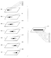
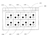
画像501〜507は7枚のレイヤー画像であり、3次元的に異なる空間位置に複数の観察対象が含まれる被写体に対して、焦点位置を光軸方向(Z方向)に順次変更しながら7回撮像を行うことで得られたものである。508〜510は取得された画像501中に含まれる観察対象を示す。観察対象508は画像503の焦点位置ではピントが合うが、画像501の焦点位置ではボケた像となる。そのため、画像501では観察対象508の構造把握は困難である。観察対象509は画像502の焦点位置でピントが合うが、画像501の焦点位置では若干ボケた像となる。画像501では観察対象509の構造把握は十分ではないものの、可能な状況にある。観察対象510は画像501の焦点位置でピントが合うため、画像501により構造把握が十分に行える。
図3において、黒で塗りつぶされた観察対象は合焦するもの、白抜きの観察対象は若干ボケるもの、破線で示した観察対象はボケるもの、をそれぞれ表している。すなわち、画像501、502、503、504、505、506、507において、観察対象510、511、512、513、514、515、516にそれぞれピントが合う。なお、図3に示す例では、観察対象510〜516は水平方向に位置が異なっているものとして説明する。
In FIG. 3, the observation target filled in black represents what is in focus, the white observation target is slightly blurred, and the observation target indicated by a broken line is blurred. That is, in the
画像517は、画像501〜507における焦点の合った観察対象510〜516の領域をそれぞれ切り出し、それらの合焦領域を合成して得られた画像を示している。上記のように複数の画像の合焦領域をつなぎ合わせることにより、画像の全領域でピントの合った深度合成画像を取得することができる。このようにデジタル画像処理によって被写界深度の深い画像を生成する処理は焦点合成(フォーカス・スタッキング)あるいは深度拡大とも呼ばれる。
An
(焦点固定で被写界深度を変化させる処理)
図4は、焦点位置を固定したまま被写界深度を変化させるという観察の仕方をバーチャル・スライド装置にて実現するための方法を示す概念図である。図4を用いて本実施形態の特徴である深度合成処理の基本的な考え方を説明する。
(Process to change depth of field with fixed focus)
FIG. 4 is a conceptual diagram showing a method for realizing the observation method of changing the depth of field while fixing the focal position with the virtual slide device. The basic concept of the depth synthesis process, which is a feature of this embodiment, will be described with reference to FIG.
焦点位置601〜607は図3における画像501〜507に対応するものであり、601から607へと同じピッチで焦点位置が光軸方向にシフトしている。以下、焦点位置604を基準(固定)にして深度合成を行う例を説明する。
The
608、617、619、621は深度合成処理が行われた後の被写界深度を示している。本例ではそれぞれのレイヤー画像の被写界深度は608で示される範囲である。画像609は、焦点位置604のレイヤー画像、すなわち深度合成が行われていない画像を示している。610〜616は、それぞれ、焦点位置601〜607で最も焦点の合う領域を示している。画像609では、領域613に焦点が合い、領域612、614は若干ボケ、それ以外の領域610、611、615、616は完全にボケている。
617は608に比べ深い被写界深度を示している。合成画像618は、617の範囲に含まれる3枚のレイヤー画像から深度合成処理が行われた結果である。合成画像618では、画像609に比べて焦点が合っている領域(合焦範囲)が増えており、領域612〜614の範囲で焦点が合っている。同様に、619、621に示すように合成処理に使用するレイヤー画像の枚数を増やすにつれて、それぞれに対応する合成画像620、622では焦点の合っている領域(合焦範囲)が広がっていく。合成画像620では領域611〜615の範囲が、合成画像622では領域610〜616の範囲がそれぞれ焦点の合っている領域(合焦範囲)である。
上記のような画像609、618、620、622を作成し、これらの画像を自動若しくはユーザー操作により切り替えて表示すれば、焦点位置(この例では604)を固定したまま被写界深度を深くしたり浅くしたりする観察が実現できる。なお、図4の例では、焦点位置を中心にして上下に等しく被写界深度を拡大/縮小させているが、焦点位置の上側又は下側の被写界深度のみ拡大/縮小したり、上側と下側を異なる割合で拡大/縮小したりすることもできる。
If the
(画像処理装置の動作)
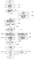
次に、本実施形態における画像処理装置102の動作を、図5〜図9を用いて説明する。なお、以下に述べる処理は、特にことわりの無いかぎり、画像処理装置102のCPUがプログラムを実行することにより実現されるものである。
(Operation of image processing device)
Next, the operation of the
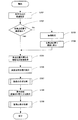
図5は、メイン処理のフローを示している。処理が開始されるとステップS701において、画像処理装置102が範囲指定画面を表示装置103に表示する。範囲指定画面では、深度合成処理の対象とする水平方向(XY方向)の範囲の指定が行われる。図8Aは、範囲指定画面の一例である。画像表示ウィンドウ1001の領域1002には、ある焦点位置で撮影されたレイヤー画像の全体が表示される。ユーザーは、マウスのドラッグ若しくはキーボードからの数値入力などにより、対象範囲1003のXY方向の位置およびサイズを指定することができる。例えば、ユーザーが、領域1002に表示された検体画像の中で、深さ方向(Z方向)の詳細観察が必要と判断した部分を対象範囲1003に指定する、という使い方が想定される。画像全体について深さ方向の観察が必要な場合は、画像の全範囲を指定すればよい。なお、1004は操作終了ボタンを示しており、このボタン1004が押下されることにより画像表示ウィンドウ1001が閉じられる。
FIG. 5 shows the flow of the main process. When the process is started, the
範囲指定が完了すると、ステップS702において、画像処理装置102は、必要な数の焦点位置におけるレイヤー画像が撮像済みか否か判定する。撮像済みでない場合、画像処理装置102は、ステップS703において、撮像開始位置と終了位置、撮像ピッチ等の撮像パラメータを撮像装置101に送信し、撮像を要求する。ステップS704では、撮像装置101が、指定された撮像パラメータに従って各焦点位置での撮像を行い、得られたレイヤー画像群を画像処理装置102に送信する。画像は画像処理装置102内の記憶装置に保存される。
When the range specification is completed, in step S702, the
次に、画像処理装置102は、深度合成処理の対象となる複数のレイヤー画像を記憶装置から取得する(ステップS705)。また、画像処理装置102は、深度合成の設定画面を表示装置103に表示し、基準となる焦点位置および被写界深度の範囲等のパラメータ指定をユーザーに行わせる(ステップS706)。
Next, the
図9は、設定画面の一例である。1101は、設定ウィンドウを示している。1102は、深度合成処理の基準位置となる焦点位置を設定するためのエディットボックスである。1103は、前記基準位置から上側の合成範囲ステップを設定するためのエディットボックスである。1104は、前記基準位置から下側の合成範囲ステップを設定するためのエディットボックスである。図9においては、上側の合成ステップが2、下側の合成ステップが1、基準位置が6、焦点位置の総数が9の場合の例を示している。深度合成処理時の被写界深度は、設定されたステップ値の整数倍で変化させる。つまり、図9の設定例では、最小合成範囲は位置4〜位置7、最大合成範囲は位置2〜位置8であり、2枚の深度合成画像が生成されることとなる。
FIG. 9 is an example of a setting screen.
1105は、基準位置および合成範囲をグラフィカルに表示する領域である。1102で指定された基準位置がわかるように、基準位置の線1106のみ、他の画像(焦点位置)を示す線に比べて太さ、長さ、色などを変えた強調表示が行われる。1107は被写界深度の最小範囲(最小合成範囲)を示し、1108は被写界深度の最大範囲(最大合成範囲)を示している。
1109は基準位置における画像を示している。この例では、焦点位置6の画像のうち、ステップS701で指定された対象範囲内の部分画像のみが表示されている。このように部分画像1109を表示することにより、ユーザーは、注目する観察対象が対象範囲内に含まれているかどうかや各観察対象のボケ具合を確認しながら、深度合成処理のパラメータを指定することが可能となる。1110は合成処理開始ボタンである。
なお、図9は設定画面の一具体例を示すものにすぎず、少なくとも基準位置と被写界深度の変化範囲を指定できさえすれば、どのような形式の設定画面を用いてもよい。例えば、エディットボックスではなくプルダウンリストやコンボボックスなどにより、基準位置やステップ値を選択できるようにしてもよい。また、1105のようなGUI上で、マウスのクリックにより基準位置や被写界深度の範囲を指定させる方法を用いてもよい。 Note that FIG. 9 is merely a specific example of the setting screen, and any type of setting screen may be used as long as at least the reference position and the change range of the depth of field can be designated. For example, the reference position and the step value may be selected by a pull-down list or a combo box instead of the edit box. Also, a method of designating a reference position and a range of depth of field by clicking the mouse on a GUI such as 1105 may be used.
設定入力後、ユーザーが合成処理開始ボタン1110を押下すると、画像処理装置102は設定ウィンドウ1101内で設定されたパラメータを確定し、ステップS707の合成処理を開始する。合成処理のフローについては、後ほど図6を参照して詳しく説明する。
When the user presses the synthesis
ステップS708では、画像処理装置102が合成処理後の画像の表示方法をユーザーに指定させる。表示方法は、ユーザーがマウスやキーボード等を操作して表示画像を切り替える方法(ユーザー切替)と、所定の時間間隔で自動的に表示画像を切り替える方法(自動切替)とがあり、ユーザーはいずれかの方法を選択できる。なお、自動切替の場合の
切り替えの時間間隔は、予め定められた固定値を用いてもよいし、ユーザーに指定させるようにしてもよい。ステップS709においては、画像処理装置102は、ステップS708で設定された表示方法にて、合成処理後の画像の表示処理を行う。この表示処理のフローについては、後ほど図7を参照して詳しく説明する。
In step S708, the
なお、図5の例においては、深度合成処理の設定(ステップS706)は画像取得(ステップS705)より後に行われているが、例えば、深度合成処理の範囲指定(ステップS701)の直後に行ってもよい。また、図5の処理フローとは別にパラメータの設定を行っておき、画像処理装置102が記憶装置に保存されたパラメータを必要なタイミングで読み出すようにしてもよい。
In the example of FIG. 5, the setting of the depth synthesis process (step S706) is performed after the image acquisition (step S705). For example, it is performed immediately after the range designation of the depth synthesis process (step S701). Also good. In addition, parameters may be set separately from the processing flow of FIG. 5, and the
(ステップS707:合成処理)
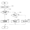
次に図6を用いてステップS707の合成処理フローの詳細を説明する。
(Step S707: Composition processing)
Next, details of the composition processing flow in step S707 will be described with reference to FIG.
画像処理装置102は、ステップS801において合成処理の対象となる画像群から任意の画像を選択する。続いて、画像処理装置102は、選択された画像を記憶装置から読み込み(ステップS802)、その画像を所定サイズのブロックに分割し(ステップS803)、分割したブロック毎にコントラストの度合いを示す値を算出する(ステップS804)。コントラスト検出処理の具体例としては、ブロック毎に離散コサイン変換を行って周波数成分を求め、周波数成分の中で高周波成分の総和を求め、コントラストの度合いを示す値として採用する方法が挙げられる。ステップS805では、画像処理装置102は、ステップS706で指定された最大合成範囲に含まれる画像全てに対して、コントラスト検出処理が実行されたか否かを判断する。コントラスト検出処理が終わっていない画像が残っている場合には、画像処理装置102は、未処理の画像を次に処理する画像として選択し(ステップS806)、ステップS802〜S804の処理を実行する。ステップS805において全ての画像に対してコントラスト検出処理が終了していると判断されると、処理はステップS807に移行する。
In step S <b> 801, the
ステップS807〜S811は、被写界深度の異なる複数の合成画像を生成する処理である。例えば、図9の例では、被写界深度1107と1108の2枚の合成画像が生成されることとなる。
Steps S807 to S811 are processes for generating a plurality of composite images having different depths of field. For example, in the example of FIG. 9, two composite images with depths of
まずステップS807において、画像処理装置102は、最初に合成処理を行う被写界深度を決める。そして、画像処理装置102は、決定された被写界深度に含まれる複数の画像の中から、ブロック毎にコントラストが最も高い画像を選択し(ステップS808)、ブロック毎に選ばれた複数の部分画像を繋ぎ合せて1枚の合成画像を生成する(ステップS809)。ステップS810では、画像処理装置102は、指定された全ての被写界深度に対して合成処理が終了しているか否かを判断する。画像処理装置102は、合成処理が終了していない被写界深度が存在する場合には、ステップS808、S809の処理を繰り返す(ステップS810、S811)。
First, in step S <b> 807, the
上述の説明では、空間周波数に基づいてコントラストの度合いを算出する例を示したが、ステップS804の処理はこれに限るものではい。例えば、エッジ検出フィルタを用いてエッジ検出を行い、得られたエッジ成分をコントラストの度合いとしても良い。あるいは、ブロック内に含まれる輝度値の最大値および最小値を検出し、最大値と最小値の差をコントラストの度合いとしても良い。他にも、コントラスト検出に対しては、既知の様々な方法を適用することが可能である。 In the above description, an example in which the degree of contrast is calculated based on the spatial frequency has been shown, but the processing in step S804 is not limited to this. For example, edge detection may be performed using an edge detection filter, and the obtained edge component may be used as the degree of contrast. Alternatively, the maximum value and the minimum value of the luminance values included in the block may be detected, and the difference between the maximum value and the minimum value may be used as the degree of contrast. In addition, various known methods can be applied to contrast detection.
(ステップS709:表示処理)
次に図7を用いてステップS709の表示処理フローの詳細を説明する。
(Step S709: Display processing)
Next, details of the display processing flow in step S709 will be described with reference to FIG.
画像処理装置102は、まずステップS901において、最初に表示する画像を選択する。例えば、被写界深度が最も浅い画像、あるいは、被写界深度が最も深い画像が、最初に表示する画像として選択される。そして、画像処理装置102は、選択された画像を表示装置103に表示し(ステップS902)、前述のステップS708で指定された表示方法の設定を読み込む(ステップS903)。なお、図7の例においては、表示方法の取得ステップS903はステップS902より後に行われているが、例えば、選択画像の表示ステップS902の前に表示方法の取得を行ってもよい。
First, in step S901, the
ステップS904では、画像処理装置102は、指定された表示方法がユーザー切替(ユーザー操作による表示画像の切り替え)か自動切替かを判別し、ユーザー切替の場合はステップS905へ、自動切替の場合はステップS911へ処理を移行する。
In step S904, the
(1)ユーザー切替
ステップS905では、画像処理装置102はユーザーによる操作が行われたか否かの判別を行う。操作が無いと判断された場合はステップS905にて待機状態となる。操作が行われたと判断された場合、画像処理装置102は、マウスによるホイール操作がされたか否かを判別する(ステップS906)。ホイール操作が行われたと判断された場合、画像処理装置102は、UP操作かDOWN操作かを判別し(ステップS907)、UP操作の場合は表示画像を被写界深度が一段階深い画像へ切り替える(ステップS908)。DOWN操作の場合、画像処理装置102は、表示画像を被写界深度が一段階浅い画像へと切り替える(ステップS909)。なお、ここではホイール操作に応答して被写界深度を一段階ずつ切り替える例を示したが、マウスホイールの所定時間あたりの回転量を検出し、回転量に応じて被写界深度の変化量を変えてもよい。
(1) User switching In step S905, the
ステップS906にて、マウスホイール以外の操作がされたと判断された場合、画像処理装置102は、終了操作がされたか否かを判別する(ステップS910)。終了操作がされなかったと判別した場合、ステップ905へ進み待機状態となる。
If it is determined in step S906 that an operation other than the mouse wheel has been performed, the
(2)自動切替
ユーザー切替では、ユーザー操作にしたがって表示画像が切り替えられるのに対し、自動切替では、所定の時間間隔(tとする。)で自動的に表示画像が切り替わる。
(2) Automatic switching In the user switching, the display image is switched in accordance with the user operation, whereas in the automatic switching, the display image is automatically switched at a predetermined time interval (t).
ステップS911では、画像処理装置102は、現在の選択画像を表示(ステップS902)から、所定時間tが経過したかどうかを判断する。所定時間tが経過していないと判断された場合は、ステップS911にて待機状態となる。所定時間tが経過していたと判断された場合、画像処理装置102は、ステップS912にて、次に表示する被写界深度の画像を選択する。そして、ステップS902に戻り、表示画像が切り替わる。この表示切替は、ユーザーにより終了操作が行われるまで継続する(ステップS913)。
In step S911, the
なお、画像の選択順としては、例えば、被写界深度が最も浅い画像から連続的に被写界深度が深い画像に切り替わっていくなどの方法がある。この場合、被写界深度が最も深い画像を表示して次に選択する画像が無くなった際には、最初に表示を行った被写界深度が最も浅い画像に戻るように、表示切替をループさせてもよい。あるいは、次に選択すべき被写界深度の画像が無くなった際には、切り替え順序を反転させることで、被写界深度が最も深い画像と最も浅い画像の間で表示切替を往復させてもよい。また、次に選択すべき被写界深度の画像が無くなった場合には表示の切り替えを中止して待機状態となり、マウスクリックなどのユーザーの指示により最初から同じ表示を開始する方法などもある。更に、最初に被写界深度が最も深い画像から連続的に被写界深度が浅くなる方向に連続的に表示画像を切り替えてもよい。他にも、さまざまな表示方法が適用可能である。 As an image selection order, for example, there is a method in which an image having the shallowest depth of field is continuously switched to an image having a deep depth of field. In this case, when the image with the deepest depth of field is displayed and the next image to be selected disappears, the display switching is looped so that the image displayed first has the shallowest depth of field. You may let them. Alternatively, when there is no more depth-of-field image to be selected next, the display order can be reversed between the deepest and the shallowest images by reversing the switching order. Good. In addition, when there is no more depth-of-field image to be selected next, there is a method of stopping the display switching and entering a standby state, and starting the same display from the beginning by a user instruction such as a mouse click. Further, the display image may be continuously switched from the image having the deepest depth of field to the direction in which the depth of field is continuously reduced. In addition, various display methods can be applied.
図8A〜図8Cは、被写界深度が異なる画像の表示例を示している。本実施形態では、範囲指定で用いた画像表示ウィンドウ1001を用いて画像の切り替え表示を行うことができる。図8Aは、被写界深度が最も浅い画像、すなわち図9の基準位置6における画像の例である。図8Bは、被写界深度が一段階深い画像、すなわち焦点位置4〜7の4枚の画像から生成された合成画像の例である。図8Cは、被写界深度がさらに一段階深い画像、すなわち焦点位置2〜8の7枚の画像から生成された合成画像の例である。図8A、図8B、図8Cの順に、ピントの合っている観察対象が増えていることが分かる。なお、被写界深度が切り替わるのは、範囲指定された領域1003内の画像部分だけであり、それ以外の部分は基準位置6の画像のまま変化しない。
8A to 8C show display examples of images with different depths of field. In the present embodiment, it is possible to perform image switching display using the
以上述べた構成によれば、ユーザーは、注目する部分に焦点を合わせたまま周囲の様子を変化させるといった観察を極めて容易に行うことができる。これにより、ユーザーは注目する部分(例えば、組織や細胞等)の2次元的な構造だけでなく3次元的な構造も容易に把握することが可能となる。また、被写界深度を変化させる範囲を指定する(絞り込む)ことができるため、高解像かつ大サイズの画像であっても高速な処理が可能となる。また、1つの表示画像の中で被写界深度の深い部分(領域1003)と浅い部分(領域1003以外の部分)を混在表示できることを利用すれば、従来の光学顕微鏡では不可能であった、3次元的観察と2次元的観察を組み合わせたユニークな観察手法も可能となる。 According to the configuration described above, the user can very easily perform observation such as changing the state of the surroundings while keeping the focus on the portion of interest. As a result, the user can easily grasp not only the two-dimensional structure of the part of interest (for example, tissue or cell) but also the three-dimensional structure. In addition, since a range in which the depth of field can be changed can be specified (narrowed down), high-speed processing is possible even for high-resolution and large-size images. Further, if it is possible to display a portion with a deep depth of field (region 1003) and a shallow portion (a portion other than the region 1003) in one display image, it was impossible with a conventional optical microscope. A unique observation method combining three-dimensional observation and two-dimensional observation is also possible.
[第2の実施形態]
本発明の第2の実施形態を説明する。第1の実施形態では、焦点位置を固定したまま被写界深度を変化させる観察方法を実現するための構成を示したが、第2の実施形態では、被写界深度を固定したまま焦点位置を変化させる観察方法を実現するための構成を示す。
[Second Embodiment]
A second embodiment of the present invention will be described. In the first embodiment, the configuration for realizing the observation method of changing the depth of field with the focal position fixed is shown. However, in the second embodiment, the focal position with the depth of field fixed. The structure for implement | achieving the observation method which changes is shown.
(システム構成)
図10は、本発明の第2の実施形態に係る画像処理システムの装置構成の全体図である。
(System configuration)
FIG. 10 is an overall view of an apparatus configuration of an image processing system according to the second embodiment of the present invention.
本実施形態における画像処理システムは、画像サーバ1201、画像処理装置102、表示装置103から構成される。第1の実施形態では、画像処理装置102は撮像装置101から画像を取得したのに対し、本実施形態では、画像サーバ1201から画像を取得する点が異なる。画像サーバ1201と画像処理装置102の間は、ネットワーク1202を介して、汎用I/FのLANケーブル1203で接続される。画像サーバ1201はバーチャル・スライド装置により撮像されたレイヤー画像を保存する大容量の記憶装置を備えたコンピュータである。画像処理装置102および表示装置103は第1の実施形態のものと同様である。
The image processing system in this embodiment includes an
図10の例では、画像サーバ1201と画像処理装置102と表示装置103の3つの装置により画像処理システムが構成されているが、本発明の構成はこの構成に限定されるものではない。例えば、表示装置が一体化した画像処理装置を用いてもよいし、画像処理装置の機能を画像サーバに組み込んでもよい。また画像サーバ、画像処理装置、表示装置の機能を1つの装置で実現することもできる。また逆に、画像サーバや画像処理装置の機能を分割して複数の装置によって実現してもよい。
In the example of FIG. 10, the image processing system is configured by three devices of the
(被写界深度固定で焦点位置を変化させる処理)
図11は、被写界深度を固定したまま焦点位置(実際は深度合成の基準位置)を変化させるという観察の仕方をバーチャル・スライド装置にて実現するための方法を示す概念図である。図11を用いて本実施形態の特徴である深度合成処理の基本的な考え方を説明する。
(Process to change focus position with fixed depth of field)
FIG. 11 is a conceptual diagram showing a method for realizing, in the virtual slide device, an observation method in which the focal position (actually the reference position for depth synthesis) is changed while the depth of field is fixed. The basic concept of the depth synthesis process, which is a feature of this embodiment, will be described with reference to FIG.
焦点位置1301〜1307は図3における画像501〜507に対応するものであり、1301から1307へと同じピッチで焦点位置が光軸方向にシフトしている。以下、深度合成処理によって3枚分の画像に相当する被写界深度をもつ合成画像を生成する例を説明する。
The
画像1309は基準位置を1302、被写界深度を1308とした場合の深度合成処理により生成された合成画像である。画像1309では、1313、1314、1315の3つの領域において焦点が合っている。
An
画像1317は基準位置を1303、被写界深度を1316とした場合の深度合成処理により生成された合成画像である。画像1317は、画像1309と被写界深度は同じであるが、基準となる焦点位置が異なる。その結果、画像1317と画像1309とでは、焦点が合っている領域の位置が変化する。画像1317では、画像1309において焦点が合っていた領域1315では焦点があっておらず、代わりに画像1309において焦点が合っていなかった領域1312において焦点が合っている。
An
画像1319は基準位置を1304、被写界深度を1318とした場合の深度合成処理により生成された合成画像である。また、画像1321は基準位置を1305、被写界深度を1320とした場合の深度合成処理により生成された合成画像である。画像1319では、焦点の合っている領域は1311〜1313であり、画像1321では、焦点の合っている領域は1310〜1312である。
An
このような合成画像1309、1317、1319、1321を作成し、これらの画像を自動若しくはユーザー操作により切り替えて表示すれば、オリジナル画像よりも深い被写界深度で、焦点位置を変化させながらの観察が実現できる。
If such
顕微鏡装置は被写界深度が浅く、焦点位置から光軸方向に少しずれただけでもボケてしまうため、注目する領域が深さ方向にある程度の広がりをもつ場合には観察が困難となる。この点、上記方法により被写界深度を所望の深度に拡大することにより、1枚の表示画像だけで、注目する領域全体に焦点が合った状態での観察が可能になる。また、焦点位置を光軸方向に移動させながら順次閲覧する際にも、被写界深度が浅いと焦点位置を少し変化させるだけでも被写体がすぐにボケてしまうため、深さ方向に隣接する画像間の関連が失われやすい。この点、上記方法によれば、合成画像同士の被写界深度の範囲が重なりを有するため、画像切替にともなう合焦状態の変化が緩やかになり、深さ方向に隣接する画像間の関連が把握しやすくなる。更に、被写界深度を所望の深度に限定して拡大させることにより、注目する被写体の周囲ではボケが残ることになる。注目する被写体の周辺のボケを残すことで奥行き感を得ることが可能になり、注目する被写体の立体感を感じながら画像を閲覧することが可能になる。 The microscope apparatus has a shallow depth of field, and even if it is slightly deviated from the focal position in the optical axis direction, it is blurred. Therefore, observation becomes difficult when the region of interest has a certain extent in the depth direction. In this regard, by enlarging the depth of field to a desired depth by the above method, it is possible to perform observation in a state where the entire region of interest is in focus with only one display image. Also, when browsing sequentially while moving the focal position in the optical axis direction, if the depth of field is shallow, the subject will immediately blur even if the focal position is slightly changed. The relationship between them is easily lost. In this regard, according to the above method, since the range of the depth of field of the composite images has an overlap, the change in the focus state due to the image switching becomes gradual, and the relationship between the adjacent images in the depth direction is reduced. It becomes easy to grasp. Furthermore, blurring remains around the subject of interest by enlarging the depth of field to a desired depth. By leaving the blur around the subject of interest, it is possible to obtain a sense of depth, and it is possible to browse images while feeling the stereoscopic effect of the subject of interest.
なお、図11における例では、合成処理時に使用される画像数(被写界深度の範囲に含まれる画像数)と、焦点の合っている領域とが同数の3である例を示した。しかし、一般的にはこの数は一致するとは限らず、焦点の合っている領域の数は基準位置毎に変化する。また、図11においては隣り合う領域に移動するように、焦点の合っている領域が変化してゆく例を示したが、実際の結果はこれに限るものではない。例えば、被写体の状態、撮像時の焦点位置、あるいは設定する被写界深度に応じて焦点の合っている領域の状況は異なる。 In the example in FIG. 11, an example is shown in which the number of images used during the synthesis process (the number of images included in the range of depth of field) and the in-focus region are the same number of three. However, in general, this number does not always match, and the number of in-focus areas varies for each reference position. Further, in FIG. 11, an example in which the in-focus area changes so as to move to the adjacent area is shown, but the actual result is not limited to this. For example, the situation of the in-focus region differs depending on the state of the subject, the focal position at the time of imaging, or the set depth of field.
(画像処理装置の動作)
本実施形態における画像処理装置102の動作を、図12〜図14を用いて説明する。
なお、メイン処理のフローは、第1の実施形態で述べた図5のものと同様である。ただし、本実施形態では、図5におけるステップS702の判定は画像サーバ1201中に撮像された画像が存在するか否かの判定となる。また、ステップS704の保存先は画像サーバ1201となる。以下、第1の実施形態と異なる処理について詳しく説明する。
(Operation of image processing device)
The operation of the
The flow of the main process is the same as that of FIG. 5 described in the first embodiment. However, in the present embodiment, the determination in step S702 in FIG. 5 is a determination as to whether or not an image captured in the
(S706:深度合成処理の設定)
図14は本実施形態における深度合成処理のパラメータを設定するための設定画面の一例である。
(S706: Setting of depth composition processing)
FIG. 14 is an example of a setting screen for setting the parameters of the depth synthesis process in the present embodiment.
1601は、設定ウィンドウを示している。1602は、基準位置から上側の深度合成範囲を設定するためのエディットボックスである。1603は、基準位置から下側の深度合成範囲を設定するためのエディットボックスである。1604は、確認用に表示する画像(1608〜1610)の基準位置を設定するためのエディットボックスである。図14においては、上側の合成範囲が1、下側の合成範囲が2、画像確認用の基準位置が3の場合の例を示している。この場合、基準位置の画像を含む4枚の画像から合成画像が生成されることになる。
1605は、1602〜1604で指定された内容をグラフィカルに表示する領域である。画像確認用の基準位置が容易にわかるように、その基準位置の線1606のみ、他の画像(焦点位置)を示す線に比べて太さ、長さ、色などを変えた強調表示が行われる。1607は、焦点位置3を基準としたときの被写界深度の範囲を示している。
確認用に表示される画像1608、1609、1610は、それぞれ、焦点位置2、3、5における画像である。ステップS701で指定された範囲内の領域が表示されている。このように確認用の画像を表示することにより、注目する被写体全体に焦点が合うかどうかを確認しながら、合成範囲を指定することが可能となる。
なお、図14は設定画面の一具体例を示すものにすぎず、少なくとも合成範囲を指定できさえすれば、どのような形式の設定画面を用いてもよい。例えば、エディットボックスではなくプルダウンリストやコンボボックスなどにより、合成範囲等を選択できるようにしてもよい。また、1605のようなGUI上で、マウスのクリックにより合成範囲等を指定させる方法を用いてもよい。 FIG. 14 shows only a specific example of the setting screen, and any type of setting screen may be used as long as at least the composition range can be specified. For example, the synthesis range or the like may be selected not by the edit box but by a pull-down list or a combo box. Further, a method of designating a synthesis range or the like by clicking the mouse on a GUI such as 1605 may be used.
設定入力後、ユーザーが合成処理開始ボタン1610を押下すると、画像処理装置102は設定ウィンドウ1601内で設定されたパラメータを確定し、ステップS707の合成処理を開始する。
After the setting input, when the user presses the synthesis
(ステップS707:合成処理)
図12は図11に示す合成処理のフローを示すものであり、本実施形態におけるステップS707の詳細な内容を示している。図12は第1の実施形態における合成処理の詳細フローである図6に対応するものであり、同様の項目には同じ符号を付し説明は省略する。
(Step S707: Composition processing)
FIG. 12 shows the flow of the composition process shown in FIG. 11, and shows the detailed contents of step S707 in the present embodiment. FIG. 12 corresponds to FIG. 6 which is a detailed flow of the synthesizing process in the first embodiment. Similar items are denoted by the same reference numerals and description thereof is omitted.
ステップS801からステップS806までの処理は、第1の実施形態と同様に進められる。画像処理装置102は、ステップS1401において最初に合成処理を行う焦点位置(基準位置)を決めると、第1の実施形態と同様の方法で合成画像を生成する(ステップS808、S809)。ステップS1402では、画像処理装置102は、指定された全ての焦点位置に対して合成処理が終了しているか否かを判断し、未処理の焦点位置が存在する場合には、ステップS808、S809の処理を繰り返す(ステップS1403)。
The processing from step S801 to step S806 proceeds in the same manner as in the first embodiment. When the
なお、前述の説明ではステップS1402において、全ての焦点位置に対し合成処理を行うようにしている。しかし、全ての焦点位置に対して合成処理を行うようにした場合、焦点位置の上限あるいは下限において合成処理に必要な画像が不足し、指定した被写界深度の範囲で合成処理が出来ない場合がある。そこで、指定された被写界深度の範囲で合成処理を行う事が可能な焦点位置の画像に対してのみ合成処理を行うようにしてもよい。あるいは、合成処理を行う焦点位置の範囲をユーザーに指定させる等さまざまな方法が適用可能である。 In the above description, in step S1402, the synthesizing process is performed on all the focal positions. However, when combining processing is performed for all focal positions, images required for combining processing are insufficient at the upper limit or lower limit of the focal position, and combining processing cannot be performed within the specified depth of field. There is. Therefore, the synthesis process may be performed only on the image at the focal position where the synthesis process can be performed within the range of the designated depth of field. Alternatively, various methods such as allowing the user to specify the range of the focus position for performing the synthesis process can be applied.
(ステップS709:表示処理)
図13は、本実施形態における画像の表示処理の詳細フローである。図13は第1の実施形態における画像の表示処理の詳細フローである図7に対応するものであり、同様の項目には同じ符号を付し説明は省略する。
(Step S709: Display processing)
FIG. 13 is a detailed flow of image display processing in the present embodiment. FIG. 13 corresponds to FIG. 7 which is a detailed flow of the image display process in the first embodiment, and the same reference numerals are given to the same items and the description thereof is omitted.
画像処理装置102は、まずステップS1501において、最初に表示する画像を選択する。例えば、全体画像の焦点位置に最も近い画像、あるいは、全体画像の焦点位置から最も遠い画像が、最初に表示する画像として選択される。その後、第1の実施形態と同じように選択画像が表示され、指定された表示方法に従ってユーザー切替または自動切替が実行される。ユーザー切替においては、第1の実施形態ではマウスホイールのUP/DOWNで被写界深度を拡大/縮小したのに対し、本実施形態では、UPで基準位置を上に移動し(ステップS1502)、DOWNで基準位置を下に移動する(ステップS1503)。また、自動切替においては、第1の実施形態では被写界深度を切り替えたのに対し、本実施形態では基準位置を上もしくは下に順に移動する(ステップS1504)。それ以外の処理については、第1の実施形態のものと同様である。
First, in step S1501, the
以上述べた構成によれば、複数の焦点位置において所望の被写界深度で深度合成を行うことで得た複数の合成画像を観察することが可能となる。ユーザーは、被写界深度の範囲を拡大した複数の合成画像を観察することができ、複数のオリジナル画像(レイヤー画像)をそのまま観察する場合と比べ、検体の深さ方向(Z方向)の構造を容易に把握することが可能となる。 According to the configuration described above, it is possible to observe a plurality of synthesized images obtained by performing depth synthesis at a plurality of focal positions at a desired depth of field. The user can observe a plurality of composite images in which the range of the depth of field is expanded, and the structure in the depth direction (Z direction) of the specimen as compared with the case of observing a plurality of original images (layer images) as they are. Can be easily grasped.
[第3の実施形態]
本発明の第3の実施形態を説明する。本実施形態の画像処理装置102の特徴の一つは、上述の実施形態において説明した合成方法を選択的に実行して合成画像を取得可能であることである。また本実施形態の画像処理装置102の特徴の一つは、上述の実施形態において説明した表示方法、および後述する他の表示方法を選択的に実行することである。以下、これらの点を中心に説明する。
[Third Embodiment]
A third embodiment of the present invention will be described. One of the features of the
図15は本実施形態における画像取得の流れを示すフローである。画像処理装置102は、ステップS1701において、ユーザーに画像取得モードを選択させる。画像の取得先としては、画像処理装置102内のローカルの記憶装置、画像サーバ1201、撮像装置101のいずれかを選択可能である。
FIG. 15 is a flowchart showing the flow of image acquisition in this embodiment. In step S1701, the
ローカルの記憶装置が選択された場合には(ステップS1702のYes)、画像処理装置102は、自装置内の記憶装置から必要な画像を取得し、処理を終了する(ステップS1703)。画像サーバ1201が選択された場合には(ステップS1704のYes)、画像処理装置102は、ネットワークを介して画像サーバ1201から必要な画像を取得し、処理を終了する(ステップS1705)。撮像装置101が選択された場合には(ステップS1704のNo)、画像処理装置102は撮像のパラメータ及びリクエストを撮像装置101に送信して撮像を行わせ、その結果得られた画像を取得する(ステップ
S1706)。
If a local storage device is selected (Yes in step S1702), the
なお、画像取得方法は図15に示す内容に限定されるものではない。例えば、画像取得先の選択肢は、画像処理装置102、画像サーバ1201、撮像装置101のうちの2つでもよい。あるいは、専用線で接続されたストレージ、メモリカード等の記録媒体、他のコンピュータ、他のバーチャル・スライド・システムなど、画像取得先の選択肢をさらに増やすこともできる。
The image acquisition method is not limited to the content shown in FIG. For example, two options of the
次に、本実施形態における処理フローを、図16を用いて説明する。なお、前述した図5の処理フローの内容と同様の項目には同じ符号を付し、説明は省略する。 Next, the processing flow in this embodiment is demonstrated using FIG. In addition, the same code | symbol is attached | subjected to the item similar to the content of the processing flow of FIG. 5 mentioned above, and description is abbreviate | omitted.
ステップS701からS705までは前述の実施形態と同様に処理が実行される。そして、ステップS1801において、画像処理装置102は、図17Aに示す合成処理モード指定画面1901を表示し、ユーザーに合成処理モードを選択させる。合成処理モードとしては、第1の実施形態で述べた焦点位置固定モード1902と第2の実施形態で述べた被写界深度固定モード1903のいずれかを選択可能である。
In steps S701 to S705, processing is executed in the same manner as in the above-described embodiment. In step S1801, the
ステップS1802では、ステップS1801の選択結果に応じて処理の分岐が行われ、焦点位置固定モードが選択された場合にはステップS1803へ移行する。画像処理装置102は図9の設定画面を表示して焦点位置固定モード用の深度合成処理の設定をユーザーに行わせ(ステップS1803)、次いで焦点位置固定の合成処理を実行する(ステップS1804)。一方、被写界深度固定モードが選択された場合、画像処理装置102は図14の設定画面を表示して被写界深度固定モード用の深度合成処理の設定をユーザーに行わせ(ステップS1805)、次いで被写界深度固定の合成処理を実行する(ステップS1806)。
In step S1802, the process is branched according to the selection result in step S1801, and when the focus position fixing mode is selected, the process proceeds to step S1803. The
次に、ステップS1807において、画像処理装置102は、図17Bに示す表示モード指定画面2001を表示し、ユーザーに表示モードを指定させる。表示モードとしては、1枚表示モード2002と並列表示モード2003のいずれかを選択可能である。
Next, in step S1807, the
1枚表示モードが選択された場合には(ステップS1808のYes)、画像処理装置102は、図8A〜図8Cに示すように、複数の合成画像を1枚ずつ時分割で順番に切り替えながら表示する(ステップS1809)。一方、並列表示モードが選択された場合には(ステップS1808のNo)、画像処理装置102は、並列表示モードにより表示を行う(ステップS1810)。
When the single image display mode is selected (Yes in step S1808), the
図18はステップS1810において実行される並列表示モードの画面例である。画像表示ウィンドウ2101の中に、複数の合成画像2102〜2109が空間的に並べて表示されている。なお、並列表示モードの表示方法は図18の例に限定されるものではない。例えば、全ての画像ではなく、一部の複数の画像を画像表示ウィンドウに並べて表示し、マウスなどによるスクロール操作で表示画像を順次切り替えるようにしてもよい。その他、並列表示モードにおいては少なくとも2枚以上の画像が同時に異なる位置に表示され、ユーザーが複数の画像を比較可能な表示方法であればどのような方法であってもよい。
FIG. 18 is a screen example of the parallel display mode executed in step S1810. In the
合成処理モードの選択方法は上述の方法以外でも良い。例えば、画像処理装置102が、プログラム起動時等に図17Aの画面を表示して合成処理モードをユーザーに選択させ、選択結果を保存しておいたものをステップS1802で読み込むようにしてもよい。更に、図17Aに示すようなモード選択のみを行うウィンドウを設けるのではなく、図9および図14に示す合成処理設定画面に合成処理モードを選択するUIを設けても良い。
The method for selecting the synthesis processing mode may be other than the method described above. For example, the
同様に、表示モードの選択方法についても上述の方法以外でも良い。例えば、画像処理装置102が、プログラム起動時等に図17Bの画面を表示して表示モードをユーザーに選択させ、選択結果を保存しておいたものをステップS1808で読み込むようにしてもよい。更に、図17Bに示すようなモード選択のみを行うウィンドウを設けるのではなく、図8、および図18の画像表示画面に表示モードを選択するUIを設けても良い。
Similarly, the display mode selection method may be other than the above-described method. For example, the
本実施形態では、合成処理モードおよび表示モードを双方変更可能な例を示したが、これに限るものではなく、いずれか一方のみ変更可能な構成であっても構わない。また、合成処理モードの選択に関しては、他の画像処理への切り替えのための選択肢が含まれていても構わない。同様に、表示モードの選択に関しては、他の表示モードへの切り替えのための選択肢が含まれていても構わない。他の表示モードの例としては、例えば深度合成処理を行っていないオリジナル画像(レイヤー画像)のみの表示モード等が挙げられる。あるいは、深度合成処理後の画像と深度合成処理を行っていない画像の両方を比較可能に表示するモード等が挙げられる。深度合成処理後の画像と深度合成処理を行っていない画像を比較可能に表示する表示モードも設けることにより、深度合成処理により他の画像から切り出され合成された領域の撮像時の状態を把握することが可能となる。そのため、明瞭な状態と奥行き感のある状態を両方比較しながら画像を閲覧することが可能となる。 In the present embodiment, an example in which both the synthesis processing mode and the display mode can be changed has been described. However, the present invention is not limited to this, and a configuration in which only one of them can be changed may be used. Further, regarding the selection of the composition processing mode, options for switching to another image processing may be included. Similarly, regarding the selection of the display mode, options for switching to another display mode may be included. Examples of other display modes include, for example, a display mode for only an original image (layer image) that has not been subjected to depth composition processing. Or the mode etc. which display so that both the image after a depth synthetic | combination process and the image which has not performed the depth synthetic | combination process are comparable are mentioned. By providing a display mode in which images after depth synthesis processing and images that have not been subjected to depth synthesis processing are displayed in a comparable manner, the state at the time of imaging a region that has been cut out from other images and synthesized by depth synthesis processing is grasped It becomes possible. Therefore, it is possible to browse images while comparing both a clear state and a state with a sense of depth.
以上説明した構成により、複数の焦点位置における撮像結果を所望の方法で合成処理させることが可能となる。また、前記合成処理結果を所望の方法で表示させることが可能になる。その結果、ユーザーは、合成処理モードおよび表示モードを選択的に切り換えることにより、被写体の撮像結果に応じて最適な合成処理結果および表示結果を得ることが可能となる。 With the configuration described above, it is possible to combine the imaging results at a plurality of focal positions by a desired method. In addition, it is possible to display the synthesis processing result in a desired method. As a result, the user can obtain an optimum combination processing result and display result according to the imaging result of the subject by selectively switching between the combination processing mode and the display mode.
[その他の実施形態]
上述した実施形態は本発明の一具体例を示すものにすぎず、本発明の構成はそれらの具体例に限定されるものではない。
[Other Embodiments]
The above-described embodiments are merely examples of the present invention, and the configuration of the present invention is not limited to these specific examples.
例えば、第1と第2の実施形態ではユーザー切替と自動切替を選択可能としたが、どちらか一方の表示方法のみであってもよい。また、ユーザー切替と自動切替を組み合わせても良い。また、範囲指定を行わず、図8Aの1002に表示されている領域全体に対して合成処理を施して合成処理後の画像を表示するようにしても良い。更に、切り替えながら表示する画像は合成処理後の画像のみならず、合成処理前の各焦点位置における画像(レイヤー画像)を含むようにしても良い。この場合、合成処理結果の画像のみを表示するモード、合成処理前の画像のみを表示するモード、合成処理結果の画像および合成処理前の画像全てを表示するモードを選択できるようにしても良い。 For example, in the first and second embodiments, user switching and automatic switching can be selected, but only one of the display methods may be used. Further, user switching and automatic switching may be combined. In addition, without specifying the range, the entire area displayed in 1002 of FIG. 8A may be subjected to the combining process to display the image after the combining process. Furthermore, the image displayed while switching may include not only the image after the synthesis process but also an image (layer image) at each focal position before the synthesis process. In this case, a mode for displaying only the image of the synthesis process result, a mode for displaying only the image before the synthesis process, and a mode for displaying all the image of the synthesis process result and the image before the synthesis process may be selected.
また上記実施形態では、被写界深度の変化範囲や基準位置などのパラメータを閲覧前に指定させるフローを示したが、これに限るものではい。例えば事前に設定したパラメータを保存しておき、範囲指定(1003)がされた時点もしくはプログラム起動時に、保存されていたパラメータが読み込まれるようにしてもよい。このようにすることで、図9や図14に示す設定画面を表示させる必要が無くなり、図8Aの画像表示画面のみの操作で所望の画像観察が可能となる。 In the above embodiment, the flow for specifying parameters such as the change range of the depth of field and the reference position before browsing has been described. However, the present invention is not limited to this. For example, parameters set in advance may be saved, and the saved parameters may be read when the range is specified (1003) or when the program is started. In this way, it is not necessary to display the setting screen shown in FIG. 9 or FIG. 14, and a desired image can be observed by operating only the image display screen of FIG. 8A.
また、第1と第2の実施形態では、焦点位置と被写界深度のいずれか一方を固定し、他方を変化させる処理を例示した。しかし本発明はこれに限定されるものではなく、例えば、焦点位置および被写界深度の両方を変化させた合成画像を生成し、それらの合成画像を切替表示できるようにしてもよい。この場合、焦点固定・被写界深度可変モード、被写界深度固定・焦点可変モード、焦点可変・被写界深度可変モードの3つのモードが選択可能である。 In the first and second embodiments, the process of fixing either one of the focal position and the depth of field and changing the other is exemplified. However, the present invention is not limited to this. For example, a composite image in which both the focus position and the depth of field are changed may be generated, and the composite image may be switched and displayed. In this case, three modes can be selected: fixed focus / depth of field variable mode, fixed depth of field / variable focus mode, and variable focus / depth of field variable mode.
さらには、第1から第3の実施形態で説明してきた構成をお互いに組み合わせることもできる。例えば、第1の実施形態のシステム構成において第2の実施形態の画像合成処理および画像表示処理を行うこともできるし、逆に第2の実施形態のシステム構成において第1の実施形態の画像合成処理および画像表示処理を行うこともできる。 Furthermore, the configurations described in the first to third embodiments can be combined with each other. For example, the image composition process and the image display process of the second embodiment can be performed in the system configuration of the first embodiment. Conversely, the image composition of the first embodiment is performed in the system configuration of the second embodiment. Processing and image display processing can also be performed.
第1から第3の実施形態では、1枚の観察用画像を生成する合成処理を、選択する原画像(レイヤー画像)の組み合わせを異ならせながら複数回実行することによって、複数の観察用画像を生成する画像合成処理を用いていた。しかし、それぞれの実施形態において、1枚の観察用画像を生成する合成処理を、選択する原画像の組み合わせを異ならせずに合成処理に関するパラメータを異ならせながら複数回実行することによって、複数の観察用画像を生成しても良い。すなわち、合成処理に関するパラメータを変化させることで、同じ組み合わせの原画像群から、被写界深度及び/又は焦点位置が互いに異なる複数の観察用画像を生成するのである。そのとき、取得した全ての原画像(例えば、Zスタック画像を構成する全てのレイヤー画像)を常に画像合成処理に用いることとしてもよい。図19は合成処理のフローの一例を示している。このフローは図5のステップS707の詳細である。画像処理装置102は、合成処理で用いる原画像(レイヤー画像)の組み合わせを決定し、それらを記憶装置から読み込む(ステップS1901)。次に、画像処理装置102は、最初の被写界深度を決め(ステップS1902)、その被写界深度に対応する合成処理のパラメータを決定する(ステップS1903)。被写界深度の調整項となるパラメータの種類は、合成処理の方法に依存して決まり、例えば、合成の係数(重み)、フィルタの特性、絞り、視点など様々なものが想定される。次に、画像処理装置102は、ステップS1903で決定したパラメータを用いて合成処理を実行し、所望の被写界深度の画像を生成する(ステップS1904)。被写界深度の指定を更新し(ステップS1906)、パラメータを変更しながら合成処理を繰り返すことで、被写界深度が異なる複数の観察用画像を生成できる(ステップS1903〜S1905)。
In the first to third embodiments, a plurality of observation images can be obtained by executing a composition process for generating one observation image a plurality of times while changing a combination of original images (layer images) to be selected. The image composition processing to be generated was used. However, in each of the embodiments, a plurality of observations are performed by executing the synthesis process for generating one observation image multiple times while changing the parameters related to the synthesis process without changing the combination of the original images to be selected. An image for use may be generated. That is, by changing the parameters related to the synthesis process, a plurality of observation images having different depths of field and / or focal positions are generated from the same combination of original image groups. At that time, all acquired original images (for example, all layer images constituting the Z stack image) may be always used for the image composition processing. FIG. 19 shows an example of the flow of composition processing. This flow is details of step S707 in FIG. The
図19のステップS1904で用いる画像合成処理には、公知の様々な被写界深度制御技術を適用できる。例えば、前述したような複数のレイヤー画像のそれぞれにおける合焦領域を選択・結合して1枚の画像(観察用画像)を生成する第一の方式(パッチ型方式)を利用してもよい。また、レイヤー画像とボケ関数をデコンボリューションさせることによって所望の深度制御画像を生成するフィルタ型方式を利用することもできる。フィルタ型方式には、各レイヤー画像と各レイヤーにおける2次元ボケ関数を足し合わせ、それらをデコンボリューションさせる第二の方式(2次元フィルタ型方式)と、複数のレイヤー画像全体に所望のボケ関数を直接デコンボリューションさせる第三の方式(3次元フィルタ型方式)がある。第三の方式に関する技術は、例えば、特開2007−128009号公報に開示されている。特開2007−128009号公報には、焦点位置の異なる複数枚の画像に対し、画像が3次元のコンボリューションモデルに合致するように座標変換処理と、3次元周波数空間上でぼけを変える3次元フィルタリング処理とを施すことで被写界深度を拡大する構成が開示されている。この被写界深度制御技術を画像合成処理(焦点合成)に適用することで、全ての原画像、又は、そこから選択された同じ組み合わせの原画像群から、任意の被写界深度の画像を生成することができる。もちろん、上述した第一から第三の方式によれば、被写界深度を変更した画像を生成することができるばかりでなく、焦点位置を変更した画像を生成することもできる。その他、上記各実施形態における様々な技術を適宜組み合わせることで得られる構成も本発明の範疇に属するものである。 Various known depth-of-field control techniques can be applied to the image composition processing used in step S1904 in FIG. For example, the first method (patch type method) for generating a single image (observation image) by selecting and combining the focus areas in each of the plurality of layer images as described above may be used. Further, it is possible to use a filter type method for generating a desired depth control image by deconvolution of a layer image and a blur function. The filter type method includes a second method (two-dimensional filter type method) in which each layer image and the two-dimensional blur function in each layer are added and deconvolved, and a desired blur function is added to the entire layer image. There is a third method (three-dimensional filter type method) for direct deconvolution. A technique related to the third method is disclosed in, for example, Japanese Patent Application Laid-Open No. 2007-128009. Japanese Patent Application Laid-Open No. 2007-128009 discloses a three-dimensional coordinate transformation process for a plurality of images with different focal positions, and a blur that changes blur in a three-dimensional frequency space so that the images match a three-dimensional convolution model. A configuration for expanding the depth of field by performing filtering processing is disclosed. By applying this depth-of-field control technology to image composition processing (focus composition), images of any depth of field can be obtained from all original images or from a group of original images selected from the same combination. Can be generated. Of course, according to the first to third methods described above, it is possible not only to generate an image with a changed depth of field, but also to generate an image with a changed focal position. In addition, configurations obtained by appropriately combining various techniques in the above embodiments also belong to the category of the present invention.
また、上記実施形態では、画像の切り替えをマウスのホイール操作によって指示したが、トラックパッド、トラックボール、ジョイスティックなどのポインティングデバイスによるスクロール操作でも同じように指示することができる。また、キーボードの所定のキー(上下キーやページUP/DOWNキーなど)を用いて同じように指示することも可能
である。
In the above-described embodiment, switching of images is instructed by a mouse wheel operation, but the same can be instructed by a scrolling operation using a pointing device such as a trackpad, a trackball, or a joystick. It is also possible to give the same instruction using predetermined keys on the keyboard (up / down key, page UP / DOWN key, etc.).
101:撮像装置、102:画像処理装置、103:表示装置、1201:画像サーバ
101: Imaging device, 102: Image processing device, 103: Display device, 1201: Image server
Claims (15)
前記複数のレイヤー画像から複数の観察用画像を生成する画像生成手段と、
を備え、
前記画像生成手段は、前記複数のレイヤー画像のうちの2枚以上のレイヤー画像を深度合成することで1枚の観察用画像を生成する合成処理を複数回実行することによって前記複数の観察用画像を生成する
ことを特徴とする画像処理装置。 Image acquisition means for acquiring a plurality of layer images obtained by imaging different positions of a subject with a microscope device;
Image generating means for generating a plurality of observation images from the plurality of layer images;
With
The image generation means executes the combination processing for generating one observation image by depth combining two or more layer images of the plurality of layer images, thereby performing the plurality of observation images. Generating an image processing apparatus.
ことを特徴とする請求項1に記載の画像処理装置。 The image processing apparatus according to claim 1, wherein the image generation unit determines a combination of layer images to be selected so that images with different depths of field are different from each other.
前記第2の観察用画像の光軸方向の合焦範囲が、前記第1の観察用画像の光軸方向の合焦範囲を包含し、且つ、前記第1の観察用画像の光軸方向の合焦範囲よりも光軸方向の一方の側と他方の側とに拡大するように、前記第2の観察用画像が生成される
ことを特徴とする請求項2に記載の画像処理装置。 The plurality of observation images include a first observation image and a second observation image having a deeper depth of field than the first observation image,
The focusing range in the optical axis direction of the second observation image includes the focusing range in the optical axis direction of the first observation image, and in the optical axis direction of the first observation image. The image processing apparatus according to claim 2, wherein the second observation image is generated so as to expand to one side and the other side in the optical axis direction with respect to the focusing range.
ことを特徴とする請求項3に記載の画像処理装置。 The focusing range in the optical axis direction of the second observation image is equally enlarged on one side and the other side in the optical axis direction with respect to the focusing range in the optical axis direction of the first observation image. The image processing apparatus according to claim 3, wherein the second observation image is generated.
ことを特徴とする請求項1に記載の画像処理装置。 The image processing apparatus according to claim 1, wherein the image generation unit determines a combination of layer images to be selected so that the focal positions are different from each other.
前記画像生成手段は、前記範囲指定手段で指定された前記対象範囲内の部分についてのみ、観察用画像を生成する
ことを特徴とする請求項1〜5のいずれかに記載の画像処理装置。 It further comprises a range specifying means for allowing the user to specify the target range to be synthesized from the layer image,
The image processing apparatus according to claim 1, wherein the image generation unit generates an observation image only for a portion within the target range designated by the range designation unit.
前記画像表示手段は、前記レイヤー画像における前記対象範囲の部分に前記観察用画像をはめ込んだ画像を前記表示装置に表示する
ことを特徴とする請求項6に記載の画像処理装置。 Image display means for displaying the observation image on a display device;
The image processing apparatus according to claim 6, wherein the image display unit displays an image in which the observation image is inserted into a portion of the target range in the layer image on the display device.
前記画像表示手段は、自動で、前記表示装置に表示する観察用画像を切り替える
ことを特徴とする請求項1〜7のいずれかに記載の画像処理装置。 Image display means for displaying the observation image on a display device;
The image processing apparatus according to claim 1, wherein the image display unit automatically switches an observation image to be displayed on the display device.
前記画像表示手段は、前記表示装置に表示する観察用画像を切り替える際に、焦点位置又は被写界深度が順に変化するように、表示する観察用画像を選択する
ことを特徴とする請求項8に記載の画像処理装置。 The plurality of observation images are images in which at least one of a focal position and a depth of field is different from each other,
The said image display means selects the image for observation to display so that a focus position or a depth of field may change in order when switching the image for observation displayed on the said display apparatus. An image processing apparatus according to 1.
前記複数の観察用画像は、焦点位置と被写界深度の少なくともいずれかが互いに異なる画像であり、
前記画像表示手段は、焦点位置と被写界深度の少なくともいずれかが互いに異なる前記複数の観察用画像を空間的に並べて前記表示装置に表示する
ことを特徴とする請求項1〜9のいずれかに記載の画像処理装置。 Image display means for displaying the observation image on a display device;
The plurality of observation images are images in which at least one of a focal position and a depth of field is different from each other,
10. The image display means according to claim 1, wherein the plurality of observation images having different focus positions and depths of field are spatially arranged and displayed on the display device. An image processing apparatus according to 1.
前記画像表示手段は、前記モード指定手段で指定された表示モードに従って、複数の観察用画像を表示する
ことを特徴とする請求項8〜10のいずれかに記載の画像処理装置。 The apparatus further comprises mode specifying means for allowing the user to specify a display mode to be used from a plurality of display modes including a mode for displaying a plurality of images in a time division manner and a mode for displaying a plurality of images in a spatial arrangement.
The image processing apparatus according to claim 8, wherein the image display unit displays a plurality of images for observation according to a display mode designated by the mode designation unit.
ことを特徴とする請求項1〜11のいずれかに記載の画像処理装置。 The image processing apparatus according to claim 1, wherein the image generation unit generates the plurality of observation images by executing a filter-type combining process.
前記撮像装置から前記複数のレイヤー画像を取得する、請求項1〜12のいずれかに記載の画像処理装置と、を備える
ことを特徴とする撮像システム。 An imaging device that generates a plurality of layer images by imaging different positions of a subject with a microscope device; and
An image processing system comprising: the image processing apparatus according to claim 1, which acquires the plurality of layer images from the image capturing apparatus.
前記サーバから前記複数のレイヤー画像を取得する、請求項1〜12のいずれかに記載の画像処理装置と、を備える
ことを特徴とする画像処理システム。 A server for storing a plurality of layer images obtained by imaging different positions of a subject with a microscope device;
An image processing system comprising: the image processing apparatus according to claim 1, which acquires the plurality of layer images from the server.
前記複数のレイヤー画像から複数の観察用画像を生成するステップと、
をコンピュータに実行させるためのプログラムであって、
前記観察用画像を生成するステップでは、前記複数のレイヤー画像のうちの2枚以上のレイヤー画像を深度合成することで1枚の観察用画像を生成する合成処理を複数回実行することによって前記複数の観察用画像が生成される
ことを特徴とするプログラム。 Acquiring a plurality of layer images obtained by imaging different positions of a subject with a microscope device;
Generating a plurality of observation images from the plurality of layer images;
A program for causing a computer to execute
In the step of generating the observation image, the plurality of the plurality of layer images are subjected to a combination process for generating a single observation image by depth combining two or more layer images. A program for generating an observation image.
Priority Applications (5)
| Application Number | Priority Date | Filing Date | Title |
|---|---|---|---|
| JP2012216048A JP2014071207A (en) | 2012-09-28 | 2012-09-28 | Image processing apparatus, imaging system, and image processing system |
| PCT/JP2013/005258 WO2014049978A1 (en) | 2012-09-28 | 2013-09-05 | Image processing apparatus, imaging system, and image processing system |
| CN201380049529.6A CN104662463A (en) | 2012-09-28 | 2013-09-05 | Image processing apparatus, imaging system, and image processing system |
| EP13763325.1A EP2901199A1 (en) | 2012-09-28 | 2013-09-05 | Image processing apparatus, imaging system, and image processing system |
| US14/406,878 US20150153559A1 (en) | 2012-09-28 | 2013-09-05 | Image processing apparatus, imaging system, and image processing system |
Applications Claiming Priority (1)
| Application Number | Priority Date | Filing Date | Title |
|---|---|---|---|
| JP2012216048A JP2014071207A (en) | 2012-09-28 | 2012-09-28 | Image processing apparatus, imaging system, and image processing system |
Publications (2)
| Publication Number | Publication Date |
|---|---|
| JP2014071207A true JP2014071207A (en) | 2014-04-21 |
| JP2014071207A5 JP2014071207A5 (en) | 2015-11-12 |
Family
ID=49213038
Family Applications (1)
| Application Number | Title | Priority Date | Filing Date |
|---|---|---|---|
| JP2012216048A Abandoned JP2014071207A (en) | 2012-09-28 | 2012-09-28 | Image processing apparatus, imaging system, and image processing system |
Country Status (5)
| Country | Link |
|---|---|
| US (1) | US20150153559A1 (en) |
| EP (1) | EP2901199A1 (en) |
| JP (1) | JP2014071207A (en) |
| CN (1) | CN104662463A (en) |
| WO (1) | WO2014049978A1 (en) |
Cited By (6)
| Publication number | Priority date | Publication date | Assignee | Title |
|---|---|---|---|---|
| JP2016126129A (en) * | 2014-12-26 | 2016-07-11 | 株式会社島津製作所 | Optical observation device |
| US10303120B2 (en) | 2016-03-28 | 2019-05-28 | Fuji Xerox Co., Ltd. | Digital holographic apparatus |
| JP2019515362A (en) * | 2016-02-09 | 2019-06-06 | モレキュラー デバイシーズ, エルエルシー | System and method for image analysis of multidimensional data |
| WO2020012825A1 (en) * | 2018-07-13 | 2020-01-16 | 富士フイルム株式会社 | Image generation device, image generation method, and image generation program |
| WO2020174862A1 (en) * | 2019-02-28 | 2020-09-03 | ソニー株式会社 | Information processing device, information processing method, and information processing system |
| WO2022259647A1 (en) * | 2021-06-09 | 2022-12-15 | ソニーグループ株式会社 | Information processing device, information processing method, and microscope system |
Families Citing this family (18)
| Publication number | Priority date | Publication date | Assignee | Title |
|---|---|---|---|---|
| JP6455829B2 (en) * | 2013-04-01 | 2019-01-23 | キヤノン株式会社 | Image processing apparatus, image processing method, and program |
| DE102014003145A1 (en) * | 2014-03-04 | 2015-09-10 | Carl Zeiss Microscopy Gmbh | Method for correcting spherical aberration in microscopic applications |
| US10412374B2 (en) * | 2014-04-10 | 2019-09-10 | Sony Corporation | Image processing apparatus and image processing method for imaging an image by utilization of a pseudo image |
| DE102015103426B4 (en) * | 2015-03-09 | 2020-07-02 | Carl Zeiss Meditec Ag | Microscope system and method for automated alignment of a microscope |
| JP6750194B2 (en) * | 2015-06-19 | 2020-09-02 | ソニー株式会社 | Medical image processing apparatus, medical image processing method, and medical observation system |
| US9894285B1 (en) * | 2015-10-01 | 2018-02-13 | Hrl Laboratories, Llc | Real-time auto exposure adjustment of camera using contrast entropy |
| JP6598660B2 (en) * | 2015-12-01 | 2019-10-30 | キヤノン株式会社 | Image processing apparatus and image processing method |
| CN106097353B (en) * | 2016-06-15 | 2018-06-22 | 北京市商汤科技开发有限公司 | Method for segmenting objects and device, computing device based on the fusion of multi-level regional area |
| JP6706167B2 (en) * | 2016-07-15 | 2020-06-03 | オリンパス株式会社 | Imaging device, image synthesizing method, and program |
| CN108810326B (en) * | 2017-04-27 | 2022-11-18 | 中兴通讯股份有限公司 | Photographing method and device and mobile terminal |
| EP3741113B1 (en) | 2018-01-19 | 2022-03-16 | PCMS Holdings, Inc. | Multi-focal planes with varying positions |
| JP2021518701A (en) | 2018-03-23 | 2021-08-02 | ピーシーエムエス ホールディングス インコーポレイテッド | Multifocal plane-based method (MFP-DIBR) for producing a stereoscopic viewpoint in a DIBR system |
| CN108961419B (en) * | 2018-06-15 | 2023-06-06 | 重庆大学 | Microscopic visual field space digitizing method and system for microscopic visual system of micro assembly system |
| CN112585963B (en) | 2018-07-05 | 2024-04-09 | Pcms控股公司 | Method and system for 3D-aware near-eye focal plane overlay of content on 2D displays |
| EP4270944A3 (en) * | 2018-07-06 | 2024-01-03 | InterDigital VC Holdings, Inc. | Method and system for forming extended focal planes for large viewpoint changes |
| EP4047408A4 (en) * | 2019-11-22 | 2022-12-28 | Sony Group Corporation | Image processing method, image processing device, and image processing system |
| RU2750005C1 (en) * | 2020-11-23 | 2021-06-21 | Общество с ограниченной ответственностью "Чайковская текстильная компания" (ООО "Чайковская текстильная компания") | Method for manufacturing antibacterial fabric with oil-, water, and dirt-repellent properties |
| CN115598822B (en) * | 2022-12-15 | 2023-03-10 | 达州爱迦飞诗特科技有限公司 | Intelligent multi-dimensional microscopic image acquisition and processing method |
Family Cites Families (7)
| Publication number | Priority date | Publication date | Assignee | Title |
|---|---|---|---|---|
| WO2003073365A1 (en) * | 2002-02-22 | 2003-09-04 | Bacus Research Laboratories, Inc. | Focusable virtual microscopy apparatus and method |
| JP4818592B2 (en) | 2003-07-01 | 2011-11-16 | オリンパス株式会社 | Microscope system, microscope image display system, observation object image display method, and program |
| JP5134365B2 (en) * | 2004-05-27 | 2013-01-30 | アペリオ・テクノロジーズ・インコーポレイテッド | System and method for generating and visualizing a three-dimensional virtual slide |
| JP4437228B2 (en) | 2005-11-07 | 2010-03-24 | 大学共同利用機関法人情報・システム研究機構 | Imaging apparatus and imaging method using defocus structure |
| US20110169985A1 (en) * | 2009-07-23 | 2011-07-14 | Four Chambers Studio, LLC | Method of Generating Seamless Mosaic Images from Multi-Axis and Multi-Focus Photographic Data |
| US8212915B1 (en) * | 2010-03-27 | 2012-07-03 | Lloyd Douglas Clark | Externally actuable photo-eyepiece relay lens system for focus and photomontage in a wide-field imaging system |
| JP5197785B2 (en) * | 2011-03-30 | 2013-05-15 | キヤノン株式会社 | Image processing apparatus, imaging system, and image processing system |
-
2012
- 2012-09-28 JP JP2012216048A patent/JP2014071207A/en not_active Abandoned
-
2013
- 2013-09-05 US US14/406,878 patent/US20150153559A1/en not_active Abandoned
- 2013-09-05 WO PCT/JP2013/005258 patent/WO2014049978A1/en active Application Filing
- 2013-09-05 EP EP13763325.1A patent/EP2901199A1/en not_active Withdrawn
- 2013-09-05 CN CN201380049529.6A patent/CN104662463A/en not_active Withdrawn
Cited By (10)
| Publication number | Priority date | Publication date | Assignee | Title |
|---|---|---|---|---|
| JP2016126129A (en) * | 2014-12-26 | 2016-07-11 | 株式会社島津製作所 | Optical observation device |
| JP2019515362A (en) * | 2016-02-09 | 2019-06-06 | モレキュラー デバイシーズ, エルエルシー | System and method for image analysis of multidimensional data |
| US11334743B2 (en) | 2016-02-09 | 2022-05-17 | Molecular Devices, Llc | System and method for image analysis of multi-dimensional data |
| US10303120B2 (en) | 2016-03-28 | 2019-05-28 | Fuji Xerox Co., Ltd. | Digital holographic apparatus |
| WO2020012825A1 (en) * | 2018-07-13 | 2020-01-16 | 富士フイルム株式会社 | Image generation device, image generation method, and image generation program |
| JPWO2020012825A1 (en) * | 2018-07-13 | 2021-07-15 | 富士フイルム株式会社 | Image generator, image generator and image generator |
| JP7030986B2 (en) | 2018-07-13 | 2022-03-07 | 富士フイルム株式会社 | Image generator, image generator and image generator |
| US11574384B2 (en) | 2018-07-13 | 2023-02-07 | Fujifilm Corporation | Image generation device, image generation method, and image generation program to generate a combination region image |
| WO2020174862A1 (en) * | 2019-02-28 | 2020-09-03 | ソニー株式会社 | Information processing device, information processing method, and information processing system |
| WO2022259647A1 (en) * | 2021-06-09 | 2022-12-15 | ソニーグループ株式会社 | Information processing device, information processing method, and microscope system |
Also Published As
| Publication number | Publication date |
|---|---|
| US20150153559A1 (en) | 2015-06-04 |
| WO2014049978A1 (en) | 2014-04-03 |
| EP2901199A1 (en) | 2015-08-05 |
| CN104662463A (en) | 2015-05-27 |
Similar Documents
| Publication | Publication Date | Title |
|---|---|---|
| JP5197785B2 (en) | Image processing apparatus, imaging system, and image processing system | |
| JP2014071207A (en) | Image processing apparatus, imaging system, and image processing system | |
| JP5780865B2 (en) | Image processing apparatus, imaging system, and image processing system | |
| JP6124543B2 (en) | Image processing apparatus, image processing method, image processing system, and program | |
| JP6091137B2 (en) | Image processing apparatus, image processing system, image processing method, and program | |
| WO2013100025A9 (en) | Image processing device, image processing system, image processing method, and image processing program | |
| WO2013100028A9 (en) | Image processing device, image display system, image processing method, and image processing program | |
| JP6455829B2 (en) | Image processing apparatus, image processing method, and program | |
| JP2013152426A (en) | Image processing device, image processing system, image processing method and program | |
| JP2013200640A (en) | Image processing device, image processing system, image processing method and program | |
| WO2013100029A1 (en) | Image processing device, image display system, image processing method, and image processing program | |
| WO2013100026A9 (en) | Image processing device, image processing system, image processing method, and image processing program | |
| JP5818828B2 (en) | Image processing apparatus, imaging system, and image processing system | |
| JP2015035782A (en) | Image processing device, imaging device, microscope system, image processing method, and image processing program | |
| JP2016038542A (en) | Image processing method and image processing apparatus | |
| JP6338730B2 (en) | Apparatus, method, and program for generating display data | |
| JP2016206228A (en) | Focused position detection device, focused position detection method, imaging device and imaging system | |
| JP2013250400A (en) | Image processing apparatus, image processing method, and image processing program | |
| JP2016038541A (en) | Image processing method and image processing apparatus | |
| JP2016166941A (en) | Focusing position detection device, focusing position detection method and imaging system | |
| JP2013250574A (en) | Image processing apparatus, image display system, image processing method and image processing program |
Legal Events
| Date | Code | Title | Description |
|---|---|---|---|
| A521 | Request for written amendment filed |
Free format text: JAPANESE INTERMEDIATE CODE: A523 Effective date: 20150917 |
|
| A621 | Written request for application examination |
Free format text: JAPANESE INTERMEDIATE CODE: A621 Effective date: 20150917 |
|
| A762 | Written abandonment of application |
Free format text: JAPANESE INTERMEDIATE CODE: A762 Effective date: 20160307 |