JP6720729B2 - Display controller - Google Patents
Display controller Download PDFInfo
- Publication number
- JP6720729B2 JP6720729B2 JP2016127808A JP2016127808A JP6720729B2 JP 6720729 B2 JP6720729 B2 JP 6720729B2 JP 2016127808 A JP2016127808 A JP 2016127808A JP 2016127808 A JP2016127808 A JP 2016127808A JP 6720729 B2 JP6720729 B2 JP 6720729B2
- Authority
- JP
- Japan
- Prior art keywords
- image
- display
- vehicle
- point
- unit
- Prior art date
- Legal status (The legal status is an assumption and is not a legal conclusion. Google has not performed a legal analysis and makes no representation as to the accuracy of the status listed.)
- Active
Links
- 238000003384 imaging method Methods 0.000 claims description 48
- 238000000034 method Methods 0.000 description 26
- 238000010586 diagram Methods 0.000 description 18
- 238000004364 calculation method Methods 0.000 description 16
- 235000004522 Pentaglottis sempervirens Nutrition 0.000 description 15
- 240000004050 Pentaglottis sempervirens Species 0.000 description 14
- 230000001133 acceleration Effects 0.000 description 9
- 238000006243 chemical reaction Methods 0.000 description 4
- 230000003287 optical effect Effects 0.000 description 4
- 238000002485 combustion reaction Methods 0.000 description 3
- 230000015572 biosynthetic process Effects 0.000 description 2
- 238000001514 detection method Methods 0.000 description 2
- 238000007726 management method Methods 0.000 description 2
- 239000011435 rock Substances 0.000 description 2
- 238000003786 synthesis reaction Methods 0.000 description 2
- 230000005540 biological transmission Effects 0.000 description 1
- 238000004422 calculation algorithm Methods 0.000 description 1
- 238000001914 filtration Methods 0.000 description 1
- 239000000446 fuel Substances 0.000 description 1
- 238000009434 installation Methods 0.000 description 1
- 239000004973 liquid crystal related substance Substances 0.000 description 1
- 230000000873 masking effect Effects 0.000 description 1
- 238000012986 modification Methods 0.000 description 1
- 230000004048 modification Effects 0.000 description 1
- 230000002093 peripheral effect Effects 0.000 description 1
- 239000007787 solid Substances 0.000 description 1
- 239000013589 supplement Substances 0.000 description 1
- 230000002194 synthesizing effect Effects 0.000 description 1
Images


Classifications
-
- H—ELECTRICITY
- H04—ELECTRIC COMMUNICATION TECHNIQUE
- H04N—PICTORIAL COMMUNICATION, e.g. TELEVISION
- H04N7/00—Television systems
- H04N7/18—Closed-circuit television [CCTV] systems, i.e. systems in which the video signal is not broadcast
- H04N7/181—Closed-circuit television [CCTV] systems, i.e. systems in which the video signal is not broadcast for receiving images from a plurality of remote sources
-
- G—PHYSICS
- G09—EDUCATION; CRYPTOGRAPHY; DISPLAY; ADVERTISING; SEALS
- G09G—ARRANGEMENTS OR CIRCUITS FOR CONTROL OF INDICATING DEVICES USING STATIC MEANS TO PRESENT VARIABLE INFORMATION
- G09G5/00—Control arrangements or circuits for visual indicators common to cathode-ray tube indicators and other visual indicators
- G09G5/36—Control arrangements or circuits for visual indicators common to cathode-ray tube indicators and other visual indicators characterised by the display of a graphic pattern, e.g. using an all-points-addressable [APA] memory
- G09G5/37—Details of the operation on graphic patterns
- G09G5/377—Details of the operation on graphic patterns for mixing or overlaying two or more graphic patterns
-
- B—PERFORMING OPERATIONS; TRANSPORTING
- B60—VEHICLES IN GENERAL
- B60R—VEHICLES, VEHICLE FITTINGS, OR VEHICLE PARTS, NOT OTHERWISE PROVIDED FOR
- B60R1/00—Optical viewing arrangements; Real-time viewing arrangements for drivers or passengers using optical image capturing systems, e.g. cameras or video systems specially adapted for use in or on vehicles
- B60R1/002—Optical viewing arrangements; Real-time viewing arrangements for drivers or passengers using optical image capturing systems, e.g. cameras or video systems specially adapted for use in or on vehicles specially adapted for covering the peripheral part of the vehicle, e.g. for viewing tyres, bumpers or the like
-
- B—PERFORMING OPERATIONS; TRANSPORTING
- B60—VEHICLES IN GENERAL
- B60R—VEHICLES, VEHICLE FITTINGS, OR VEHICLE PARTS, NOT OTHERWISE PROVIDED FOR
- B60R1/00—Optical viewing arrangements; Real-time viewing arrangements for drivers or passengers using optical image capturing systems, e.g. cameras or video systems specially adapted for use in or on vehicles
- B60R1/20—Real-time viewing arrangements for drivers or passengers using optical image capturing systems, e.g. cameras or video systems specially adapted for use in or on vehicles
- B60R1/22—Real-time viewing arrangements for drivers or passengers using optical image capturing systems, e.g. cameras or video systems specially adapted for use in or on vehicles for viewing an area outside the vehicle, e.g. the exterior of the vehicle
- B60R1/23—Real-time viewing arrangements for drivers or passengers using optical image capturing systems, e.g. cameras or video systems specially adapted for use in or on vehicles for viewing an area outside the vehicle, e.g. the exterior of the vehicle with a predetermined field of view
- B60R1/27—Real-time viewing arrangements for drivers or passengers using optical image capturing systems, e.g. cameras or video systems specially adapted for use in or on vehicles for viewing an area outside the vehicle, e.g. the exterior of the vehicle with a predetermined field of view providing all-round vision, e.g. using omnidirectional cameras
-
- B—PERFORMING OPERATIONS; TRANSPORTING
- B60—VEHICLES IN GENERAL
- B60R—VEHICLES, VEHICLE FITTINGS, OR VEHICLE PARTS, NOT OTHERWISE PROVIDED FOR
- B60R1/00—Optical viewing arrangements; Real-time viewing arrangements for drivers or passengers using optical image capturing systems, e.g. cameras or video systems specially adapted for use in or on vehicles
- B60R1/20—Real-time viewing arrangements for drivers or passengers using optical image capturing systems, e.g. cameras or video systems specially adapted for use in or on vehicles
- B60R1/22—Real-time viewing arrangements for drivers or passengers using optical image capturing systems, e.g. cameras or video systems specially adapted for use in or on vehicles for viewing an area outside the vehicle, e.g. the exterior of the vehicle
- B60R1/28—Real-time viewing arrangements for drivers or passengers using optical image capturing systems, e.g. cameras or video systems specially adapted for use in or on vehicles for viewing an area outside the vehicle, e.g. the exterior of the vehicle with an adjustable field of view
-
- G—PHYSICS
- G01—MEASURING; TESTING
- G01C—MEASURING DISTANCES, LEVELS OR BEARINGS; SURVEYING; NAVIGATION; GYROSCOPIC INSTRUMENTS; PHOTOGRAMMETRY OR VIDEOGRAMMETRY
- G01C21/00—Navigation; Navigational instruments not provided for in groups G01C1/00 - G01C19/00
- G01C21/26—Navigation; Navigational instruments not provided for in groups G01C1/00 - G01C19/00 specially adapted for navigation in a road network
- G01C21/265—Navigation; Navigational instruments not provided for in groups G01C1/00 - G01C19/00 specially adapted for navigation in a road network constructional aspects of navigation devices, e.g. housings, mountings, displays
-
- G—PHYSICS
- G06—COMPUTING; CALCULATING OR COUNTING
- G06F—ELECTRIC DIGITAL DATA PROCESSING
- G06F3/00—Input arrangements for transferring data to be processed into a form capable of being handled by the computer; Output arrangements for transferring data from processing unit to output unit, e.g. interface arrangements
- G06F3/14—Digital output to display device ; Cooperation and interconnection of the display device with other functional units
- G06F3/147—Digital output to display device ; Cooperation and interconnection of the display device with other functional units using display panels
-
- G—PHYSICS
- G06—COMPUTING; CALCULATING OR COUNTING
- G06T—IMAGE DATA PROCESSING OR GENERATION, IN GENERAL
- G06T11/00—2D [Two Dimensional] image generation
- G06T11/60—Editing figures and text; Combining figures or text
-
- B—PERFORMING OPERATIONS; TRANSPORTING
- B60—VEHICLES IN GENERAL
- B60R—VEHICLES, VEHICLE FITTINGS, OR VEHICLE PARTS, NOT OTHERWISE PROVIDED FOR
- B60R2300/00—Details of viewing arrangements using cameras and displays, specially adapted for use in a vehicle
- B60R2300/10—Details of viewing arrangements using cameras and displays, specially adapted for use in a vehicle characterised by the type of camera system used
- B60R2300/107—Details of viewing arrangements using cameras and displays, specially adapted for use in a vehicle characterised by the type of camera system used using stereoscopic cameras
-
- B—PERFORMING OPERATIONS; TRANSPORTING
- B60—VEHICLES IN GENERAL
- B60R—VEHICLES, VEHICLE FITTINGS, OR VEHICLE PARTS, NOT OTHERWISE PROVIDED FOR
- B60R2300/00—Details of viewing arrangements using cameras and displays, specially adapted for use in a vehicle
- B60R2300/30—Details of viewing arrangements using cameras and displays, specially adapted for use in a vehicle characterised by the type of image processing
- B60R2300/307—Details of viewing arrangements using cameras and displays, specially adapted for use in a vehicle characterised by the type of image processing virtually distinguishing relevant parts of a scene from the background of the scene
-
- B—PERFORMING OPERATIONS; TRANSPORTING
- B60—VEHICLES IN GENERAL
- B60R—VEHICLES, VEHICLE FITTINGS, OR VEHICLE PARTS, NOT OTHERWISE PROVIDED FOR
- B60R2300/00—Details of viewing arrangements using cameras and displays, specially adapted for use in a vehicle
- B60R2300/60—Details of viewing arrangements using cameras and displays, specially adapted for use in a vehicle characterised by monitoring and displaying vehicle exterior scenes from a transformed perspective
- B60R2300/607—Details of viewing arrangements using cameras and displays, specially adapted for use in a vehicle characterised by monitoring and displaying vehicle exterior scenes from a transformed perspective from a bird's eye viewpoint
-
- B—PERFORMING OPERATIONS; TRANSPORTING
- B60—VEHICLES IN GENERAL
- B60R—VEHICLES, VEHICLE FITTINGS, OR VEHICLE PARTS, NOT OTHERWISE PROVIDED FOR
- B60R2300/00—Details of viewing arrangements using cameras and displays, specially adapted for use in a vehicle
- B60R2300/80—Details of viewing arrangements using cameras and displays, specially adapted for use in a vehicle characterised by the intended use of the viewing arrangement
- B60R2300/802—Details of viewing arrangements using cameras and displays, specially adapted for use in a vehicle characterised by the intended use of the viewing arrangement for monitoring and displaying vehicle exterior blind spot views
-
- B—PERFORMING OPERATIONS; TRANSPORTING
- B60—VEHICLES IN GENERAL
- B60R—VEHICLES, VEHICLE FITTINGS, OR VEHICLE PARTS, NOT OTHERWISE PROVIDED FOR
- B60R2300/00—Details of viewing arrangements using cameras and displays, specially adapted for use in a vehicle
- B60R2300/80—Details of viewing arrangements using cameras and displays, specially adapted for use in a vehicle characterised by the intended use of the viewing arrangement
- B60R2300/8093—Details of viewing arrangements using cameras and displays, specially adapted for use in a vehicle characterised by the intended use of the viewing arrangement for obstacle warning
-
- G—PHYSICS
- G09—EDUCATION; CRYPTOGRAPHY; DISPLAY; ADVERTISING; SEALS
- G09G—ARRANGEMENTS OR CIRCUITS FOR CONTROL OF INDICATING DEVICES USING STATIC MEANS TO PRESENT VARIABLE INFORMATION
- G09G2340/00—Aspects of display data processing
- G09G2340/12—Overlay of images, i.e. displayed pixel being the result of switching between the corresponding input pixels
- G09G2340/125—Overlay of images, i.e. displayed pixel being the result of switching between the corresponding input pixels wherein one of the images is motion video
-
- G—PHYSICS
- G09—EDUCATION; CRYPTOGRAPHY; DISPLAY; ADVERTISING; SEALS
- G09G—ARRANGEMENTS OR CIRCUITS FOR CONTROL OF INDICATING DEVICES USING STATIC MEANS TO PRESENT VARIABLE INFORMATION
- G09G2380/00—Specific applications
- G09G2380/10—Automotive applications
Landscapes
- Engineering & Computer Science (AREA)
- Multimedia (AREA)
- Theoretical Computer Science (AREA)
- Physics & Mathematics (AREA)
- General Physics & Mathematics (AREA)
- Mechanical Engineering (AREA)
- Radar, Positioning & Navigation (AREA)
- Remote Sensing (AREA)
- Signal Processing (AREA)
- General Engineering & Computer Science (AREA)
- Human Computer Interaction (AREA)
- Automation & Control Theory (AREA)
- Computer Hardware Design (AREA)
- Closed-Circuit Television Systems (AREA)
- Traffic Control Systems (AREA)
- Controls And Circuits For Display Device (AREA)
- Studio Devices (AREA)
Description
本発明の実施形態は、車両の表示制御装置に関する。 Embodiments of the present invention relate to a display control device for a vehicle.
従来、車両に設置されたカメラで車両の周辺環境を撮像し、撮像された画像を車室内に設けられた表示画面を介して運転者に提供する技術がある。 Conventionally, there is a technique in which a camera installed in a vehicle captures an image of the surrounding environment of the vehicle and provides the captured image to a driver via a display screen provided in the vehicle interior.
しかしながら、例えば、運転者は、岩場などの路外地形(オフロード)を走行中において、表示画面上でいったん着目した岩が、運転を続けるうちに、表示画面のどこに表示されているのか、わからなくなってしまう場合がある。 However, for example, while driving on an off-road terrain such as a rocky field, the driver cannot know where on the display screen the rock once focused on is displayed while continuing to drive. It may disappear.
本発明の課題の一つは、ユーザが着目している対象をわかりやすく表示する表示制御装置を提供することである。 One of the problems of the present invention is to provide a display control device that displays an object the user is paying attention to in an easy-to-understand manner.
本発明の実施形態の表示制御装置は、一例として、車室内に設けられた表示画面に表示されている第1のタイミングにおける車両の周辺環境を示す第1の画像上の第1のポイントを指定する入力を受け付ける受け付け部と、第1の画像上の第1のポイントに第1の表示オブジェクトを表示する表示処理部と、第1のポイントに写っている第1の対象が、第1のタイミングの後の第2のタイミングにおける車両の周辺環境を示す第2の画像において写っている第2のポイントを、車両の移動量および車両の向きから演算された車両の状態の変化量に基づいて特定する特定部と、第2の画像とともに、第2の画像上の第2のポイントに第1の表示オブジェクトを表示する更新部と、を備えた。よって、第1の表示オブジェクトがユーザが指定した対象が写っている位置に追従せしめられるので、表示制御装置は、ユーザが着目している対象をわかりやすく表示することができる。
また、本発明の実施形態の表示制御装置は、一例として、車室内に設けられた表示画面に表示されている第1のタイミングにおける車両の周辺環境を示す第1の画像上の第1のポイントを指定する入力を受け付ける受け付け部と、第1の画像上の第1のポイントに第1の表示オブジェクトを表示する表示処理部と、第1のポイントに写っている第1の対象が、第1のタイミングの後の第2のタイミングにおける車両の周辺環境を示す第2の画像において写っている第2のポイントを特定する特定部と、第2の画像とともに、第2の画像上の第2のポイントに第1の表示オブジェクトを表示する更新部と、を備え、第1の画像は、車両に設けられた撮像装置によって第1のタイミングに撮像された画像であり、第2の画像は、車両の床下を示す画像であり、表示処理部は、第2のタイミングよりも前の第5のタイミングに撮像装置によって撮像された第5の画像から第2の画像を生成する。よって、表示制御装置は、車両の床下を示す画像を表示することができるとともに、指定された対象が写っている位置にマーキングすることができるので、ユーザにとっての利便性が向上する。
As an example, the display control device according to the embodiment of the present invention specifies the first point on the first image indicating the surrounding environment of the vehicle at the first timing displayed on the display screen provided in the vehicle interior. The receiving unit that receives the input, the display processing unit that displays the first display object at the first point on the first image, and the first target reflected at the first point have the first timing. The second point shown in the second image showing the surrounding environment of the vehicle at the second timing after is specified based on the amount of movement of the vehicle and the amount of change in the state of the vehicle calculated from the direction of the vehicle. And an updating unit that displays the first display object at the second point on the second image together with the second image. Therefore, the first display object can be made to follow the position where the target designated by the user appears, so that the display control device can easily display the target focused by the user.
Further, the display control device according to the embodiment of the present invention is, as an example, a first point on the first image showing the surrounding environment of the vehicle at the first timing displayed on the display screen provided in the vehicle interior. A reception unit that receives an input that specifies the first display object, a display processing unit that displays a first display object at a first point on the first image, and a first target that is captured at the first point is the first object. The second part on the second image together with the specifying part for specifying the second point shown in the second image showing the surrounding environment of the vehicle at the second timing after the timing of An updating unit that displays a first display object at a point, the first image is an image captured at a first timing by an imaging device provided in the vehicle, and the second image is the vehicle. The display processing unit generates a second image from the fifth image captured by the image capturing device at the fifth timing before the second timing. Therefore, the display control device can display the image showing the underfloor of the vehicle and can mark the position where the designated target is shown, which improves the convenience for the user.
また、本発明の実施形態の表示制御装置では、一例として、受け付け部は、表示画面に表示された第3の画像上の第3のポイントを指定する入力を受け付け、第3の画像は、前記第1の表示オブジェクトが表示され、第3のタイミングにおける車両の周辺環境を示す画像であり、表示処理部は、第3の画像上の第3のポイントに第2の表示オブジェクトを表示し、特定部は、第1の対象が、第3のタイミングの後の第4のタイミングにおける車両の周辺環境を示す第4の画像において写っている第4のポイントと、第3のポイントに写っている第2の対象が第4の画像において写っている第5のポイントと、を特定し、更新部は、第4の画像とともに、第4の画像上の第4のポイントに第1の表示オブジェクトを、第4の画像上の第5のポイントに第2の表示オブジェクトを、それぞれ表示する。表示制御装置は、複数の表示オブジェクトを表示し、複数の表示オブジェクトをそれぞれ対応する対象が写っている位置に追従させることができるので、ユーザによっての利便性が向上する。 In the display control device according to the embodiment of the present invention, as an example, the accepting unit accepts an input designating a third point on the third image displayed on the display screen, and the third image is The first display object is displayed and is an image showing the surrounding environment of the vehicle at the third timing, and the display processing unit displays the second display object at the third point on the third image, and specifies the second display object. The part includes a fourth point in which the first target is reflected in the fourth image showing the surrounding environment of the vehicle at the fourth timing after the third timing, and a third point in the third point. And a fifth point in which the second object appears in the fourth image, and the updating unit, together with the fourth image, the first display object at the fourth point on the fourth image, The second display object is displayed at the fifth point on the fourth image. Since the display control device can display a plurality of display objects and cause the plurality of display objects to follow the positions where the corresponding targets are captured, the convenience for the user is improved.
また、本発明の実施形態の表示制御装置では、一例として、第1の表示オブジェクトの表示様態と第2の表示オブジェクトの表示様態とが異なる。よって、ユーザは、例えば、避けて通りたい対象と、通りたいルート上の対象とを、区別してマーキングするなどの運用が可能となるので、ユーザによっての利便性がさらに向上する。 In the display control device according to the embodiment of the present invention, as an example, the display mode of the first display object and the display mode of the second display object are different. Therefore, for example, the user can perform operations such as marking objects that he/she wants to avoid and objects on a route that he/she wants to pass by distinguishing, which further improves convenience for the user.
また、本発明の実施形態の表示制御装置は、一例として、車室内に設けられた表示画面に表示されている第1のタイミングにおける車両の周辺環境を示す第1の画像上の第1のポイントを指定する入力を受け付ける受け付け部と、第1の画像上の第1のポイントに第1の表示オブジェクトを表示する表示処理部と、第1のポイントに写っている第1の対象が、第1のタイミングの後の第2のタイミングにおける車両の周辺環境を示す第2の画像において写っている第2のポイントを特定する特定部と、第2の画像とともに、第2の画像上の第2のポイントに第1の表示オブジェクトを表示する更新部と、を備え、入力は、第1のポイントを2つ指定する入力であり、特定部は、2つの第1のポイントのそれぞれに写っている第1の対象毎に、第2のポイントを特定し、表示処理部によって表示される第1の表示オブジェクトは、第1のポイント間を結ぶ線分であり、更新部によって表示される第1の表示オブジェクトは、第2のポイント間を結ぶ線分である。よって、ユーザは、例えば、通りたい軌跡を表示画面上に描画させ、描画された軌跡に沿って車両が進行するように操舵する、といった運用が可能となるので、ユーザによっての利便性が向上する。 The display control equipment of an embodiment of the present invention, as an example, the first indicating the vehicle surroundings in the first timing displayed on the display screen which is mounted in the vehicle image on the first The receiving unit that receives an input that specifies a point, the display processing unit that displays the first display object at the first point on the first image, and the first target reflected at the first point are The second part on the second image together with the specifying part for specifying the second point shown in the second image showing the surrounding environment of the vehicle at the second timing after the first timing and the second image. And an updating unit that displays the first display object at the point of, and the input is an input that specifies two first points, and the specifying unit is reflected at each of the two first points. The first display object that is displayed by the display processing unit and that identifies the second point for each first target is a line segment that connects the first points, and is the first segment displayed by the update unit. The display object is a line segment connecting the second points. Therefore, the user can perform, for example, an operation of drawing a desired trajectory on the display screen and steering the vehicle so that the vehicle follows the drawn trajectory, which improves convenience for the user. ..
また、本発明の実施形態の表示制御装置では、一例として、第1の画像は、車両に設けられ、第1の方向に向けられた第1の撮像装置によって撮像された画像であり、第2の画像は、車両に設けられ、第1の方向とは異なる第2の方向に向けられた第2の撮像装置によって撮像された画像である。指定された対象の位置が第1の撮像装置の撮像範囲から外れたとしても、指定された対象が他の撮像装置の撮像範囲に入っていれば、指定された対象の表示位置に表示オブジェクトが表示されるので、表示制御装置は、ユーザが着目している対象をわかりやすく表示することができる。 In the display control device according to the embodiment of the present invention, as an example, the first image is an image captured by the first image capturing device provided in the vehicle and oriented in the first direction, and the second image Image is an image captured by a second imaging device provided in the vehicle and oriented in a second direction different from the first direction. Even if the position of the specified target is outside the imaging range of the first imaging device, if the specified target is within the imaging range of another imaging device, the display object is displayed at the display position of the specified target. Since it is displayed, the display control device can easily display the target that the user is paying attention to.
以下、本実施形態の表示制御装置を車両1に搭載した例をあげて説明する。 Hereinafter, an example in which the display control device of the present embodiment is mounted on the vehicle 1 will be described.
<実施形態>
実施形態の車両1は、例えば、不図示の内燃機関を駆動源とする自動車、すなわち内燃機関自動車であってもよいし、不図示の電動機を駆動源とする自動車、すなわち電気自動車または燃料電池自動車等であってもよいし、それらの双方を駆動源とするハイブリッド自動車であってもよいし、他の駆動源を備えた自動車であってもよい。また、車両1は、種々の変速装置を搭載することができるし、内燃機関や電動機を駆動するのに必要な種々の装置、例えばシステムや部品等を搭載することができる。また、車両1における車輪3の駆動に関わる装置の方式、数、およびレイアウト等は、種々に設定することができる。
<Embodiment>
The vehicle 1 of the embodiment may be, for example, a vehicle using an internal combustion engine (not shown) as a drive source, that is, an internal combustion engine vehicle, or a vehicle using an electric motor (not shown) as a drive source, that is, an electric vehicle or a fuel cell vehicle. Etc., a hybrid vehicle using both of them as drive sources, or a vehicle provided with another drive source. Further, the vehicle 1 can be equipped with various transmission devices, and can be equipped with various devices necessary for driving the internal combustion engine and the electric motor, such as systems and parts. In addition, the method, number, layout, and the like of devices related to driving the
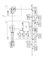
図1は、実施形態の表示制御装置を搭載する車両1の車室2aの一部が透視された状態の一例が示された斜視図である。図2は、実施形態の表示制御装置を搭載する車両1の一例が示された平面図(鳥瞰図)である。図3は、実施形態の表示制御装置を有する表示制御システム100の構成の一例を示すブロック図である。
FIG. 1 is a perspective view showing an example of a state in which a part of a vehicle interior 2a of a vehicle 1 equipped with the display control device of the embodiment is seen through. FIG. 2 is a plan view (bird's-eye view) showing an example of a vehicle 1 equipped with the display control device of the embodiment. FIG. 3 is a block diagram showing an example of the configuration of a
図1に例示されるように、車体2は、不図示のユーザが乗車する車室2aを構成している。車室2a内には、ユーザとしての運転者の座席2bに臨む状態で、操舵部4、加速操作部5、制動操作部6、および変速操作部7等が設けられている。操舵部4は、例えば、ダッシュボードから突出したステアリングホイールであり、加速操作部5は、例えば、運転者の足下に位置されたアクセルペダルであり、制動操作部6は、例えば、運転者の足下に位置されたブレーキペダルであり、変速操作部7は、例えば、センターコンソールから突出したシフトレバーである。なお、操舵部4、加速操作部5、制動操作部6、および変速操作部7は、これらには限定されない。
As illustrated in FIG. 1, the vehicle body 2 constitutes a
また、車室2a内には、表示画面8を有するモニタ装置10が設けられている。表示画面8は、例えば、LCD(liquid crystal display)またはOELD(organic electroluminescent display)等によって構成される。また、表示画面8は透明な操作入力部9で覆われている。操作入力部9は、例えばタッチパネルである。ユーザは、操作入力部9を介して表示画面8に表示される画像を視認することができる。また、ユーザは、表示画面8に表示される画像に対応した位置で手指等で操作入力部9を触れたり押したり動かしたりして操作することで、操作入力を実行することができる。モニタ装置10は、例えば、ダッシュボードの車幅方向すなわち左右方向の中央部に設けられている。また、モニタ装置10は、タッチパネル以外の操作入力部を備え得る。例えば、モニタ装置10は、他の操作入力部として、スイッチ、ダイヤル、ジョイスティック、または押しボタンが設けられていてもよい。モニタ装置10は、例えば、ナビゲーションシステムやオーディオシステムと兼用され得る。
A
また、図1、図2に示されるように、本実施形態では、例えば、車両1は、四輪自動車であり、左右二つの前輪3Fと、左右二つの後輪3Rとを有する。そして、例えば前輪3Fのタイヤ角が操舵部4の操作に対応して変化する。図3に例示されるように、車両1は、少なくとも二つの車輪3を操舵する操舵システム12を有している。操舵システム12は、アクチュエータ12aと、トルクセンサ12bとを有する。操舵システム12は、ECU14(electronic control unit)等によって電気的に制御されて、アクチュエータ12aを動作させる。操舵システム12は、例えば、電動パワーステアリングシステムや、SBW(steer by wire)システム等である。操舵システム12は、アクチュエータ12aによって操舵部4にトルク、すなわちアシストトルクを付加して操舵力を補ったり、アクチュエータ12aによって車輪3を転舵したりする。この場合、アクチュエータ12aは、一つの車輪3を転舵してもよいし、複数の車輪3を転舵してもよい。また、トルクセンサ12bは、例えば、運転者が操舵部4に与えるトルクを検出する。
Further, as shown in FIGS. 1 and 2, in the present embodiment, for example, the vehicle 1 is a four-wheeled vehicle and has two
また、本実施形態では、図2に示されるように、車両1には、車両1の周辺環境を撮像するための撮像部15(ここでは4つの撮像部15a〜15d)が設けられている。各撮像部15は、例えば、CCD(charge coupled device)、またはCIS(CMOS image sensor)、等の撮像素子を内蔵し、撮像素子によって、周辺環境が写った画像を撮像することができる、撮像装置である。各撮像部15は、所定のフレームレートで画像データを出力することができる。
Further, in the present embodiment, as shown in FIG. 2, the vehicle 1 is provided with an image capturing unit 15 (here, four
本実施形態では、撮像部15aは、車体2の前側の端部2c(例えばフロントグリル)に設置されている。撮像部15aは、車両1の前方向の周辺環境を撮像することができる。ただし、座席2bに着座した運転者が正面を向く方向、すなわち運転者からみたフロントガラス側を、車両1の前方向および車体2の前側としている。撮像部15bは、車体2の左側の端部2d、より詳しくは、左側のドアミラー2gに設けられている。撮像部15bは、車両1の左方向の周辺環境を撮像することができる。撮像部15cは、車体2の後側の端部2e、より詳しくは、リアトランクのドア2hの下方の壁部に設けられている。撮像部15cは、車両1の後方向の周辺環境を撮像することができる。撮像部15dは、車体2の右側の端部2f、より詳しくは、右側のドアミラー2gに設けられている。撮像部15dは、車両1の右方向の周辺環境を撮像することができる。
In the present embodiment, the
なお、周辺環境は、車両1の周辺の状況をいう。一例では、周辺環境は、車両1の周辺の路面を含む。また、各撮像部15が車両1の周辺環境が写っている画像を出力することができる限り、各撮像部15の構成、撮像部15の数、各撮像部15の設置箇所、および各撮像部15の向きは、上記した内容に限定されない。複数の撮像部15が写すことができる範囲が重複してもよいし、重複していなくてもよい。
The surrounding environment refers to the situation around the vehicle 1. In one example, the surrounding environment includes a road surface around the vehicle 1. Further, as long as each
図3に示されるように、表示制御システム100では、モニタ装置10、加速度センサ13、ECU(electronic control unit)14、ブレーキシステム18、舵角センサ19、アクセルセンサ20、シフトセンサ21、車輪速センサ22が、車内ネットワーク23を介して電気的に接続されている。車内ネットワーク23は、例えば、CAN(controller area network)として構成されている。ECU14は、車内ネットワーク23を通じて制御信号を送ることで、ブレーキシステム18等を制御することができる。また、ECU14は、車内ネットワーク23を介して、トルクセンサ12b、加速度センサ13、ブレーキセンサ18b、舵角センサ19、アクセルセンサ20、シフトセンサ21、および車輪速センサ22等の検出結果を受け取ることができる、また、ECU14は、操作入力部9等からの指示信号を受け取ることができる。ECU14は、表示制御装置の一例である。
As shown in FIG. 3, in the
ここで、表示制御装置の主たる特徴を説明する。 Here, the main features of the display control device will be described.
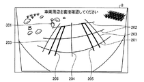
表示制御装置は、周辺環境が写っている画像を表示画面8に表示する。図4は、表示画面8の表示の一例を示す図である。この例では、表示画面8には、撮像部15aによって得られた、車両1の前方向の周辺環境を写した画像が表示されている。表示画面8には、車両1の前側の端部2cを示す線分201と、車体2の前側の端部2cからの距離が所定値である2本の線分202と、車両1が直進した場合に車体2の左右の端部2d、2fが進む経路を示す2本の線分203と、車両1が直進した場合に車体2の中心が通る経路を示す線分204と、左右二つの前輪3Fの予測経路を示す2つの表示オブジェクト205とが、車両1の前方向の周辺環境を写した画像に重畳されている。表示オブジェクト205は、例えば図4に示されるように、タイヤの幅に対応した幅を有する枠線である。以降、各線分201〜204および表示オブジェクト205を、補助情報と表記する。
The display control device displays an image showing the surrounding environment on the
図4の状態で、表示制御装置は、操作入力部9を介して、表示中の画像上のポイントを指定する操作入力を受け付けることができる。画像上のポイントは、換言すると、画像上の位置であり、画像上の座標値である。例えば運転者がポイント301をタッチすると、表示制御装置は、ポイント301にマーク401を表示する。
In the state of FIG. 4, the display control device can accept an operation input for designating a point on the image being displayed via the
図5は、マーク401が表示されている状態の表示画面8の表示の一例を示す図である。ここでは、マーク401は、円形の枠線を有する表示オブジェクトである。
FIG. 5 is a diagram showing an example of display on the
マーク401は、予め専用に用意された表示オブジェクトである。マーク401の表示様態(形状、色彩、および大きさ)は、任意に設計可能である。マーク401は、ポイント301に写っている対象を指し示すためのものであり、換言すると、ポイント301に写っている対象を表示画面8上でマーキングするためのものである。したがって、一例では、マーク401は、ポイント301に写っている対象がマーク401を介して視認可能なように、半透明に処理された表示オブジェクトである。マーク401は、枠線のみを有する表示オブジェクトであってもよい。また、マーク401の形状は、例えば、円形、矩形、または旗形である。また、表示制御装置は、マーク401の種々の表示様態をユーザに提示し、選択を促してもよい。表示制御装置は、選択された表示様態のマーク401をポイント301に表示してもよい。
The
マーク401が表示された後に運転者が車両1の運転を行うと、車両1の移動に応じて周辺環境が車両1に対して相対的に変化する。表示制御装置は、一定の周期で画像を取得して、取得した画像で表示画面8を逐次更新する。即ち、表示制御装置は、周辺環境が変化した後、表示画面8上の画像を変化後の周辺環境を写した画像で更新する。
When the driver drives the vehicle 1 after the
図6は、更新後の表示画面8の表示の一例を示す図である。表示制御装置は、図4の画像においてポイント301に写っていた対象が、更新後の画像において写っている位置を特定し、特定した位置に、マーク401を表示する。例えば、表示制御装置が、あるタイミングの周辺環境を写した画像において、ある対象(例えば岩)が写っているポイントにマーク401を表示し、その後のタイミングの周辺環境を写した更新後の画像において、その対象が写っている位置が移動した場合、その対象が写っている位置にマーク401を追従させる。運転者は、着目している対象を表示画面8上で指定することで、対象が表示されている位置にマーク401を表示させることが可能であり、かつ、運転によりその対象が写っている位置が移動した場合に、その対象が写っている位置にマーク401が追従するので、ユーザは、表示画面8上で対象を見失うことがない。即ち、実施形態の表示制御装置は、ユーザが着目している対象をわかりやすく表示することができる。
FIG. 6 is a diagram showing an example of display on the
なお、運転者は、補助情報を操舵のための参考にすることができる。表示制御装置が補助情報を表示することによって、運転者は、着目している対象と車両1の現在位置との位置関係と、着目している対象と予測される車両1の位置との位置関係とを、容易に把握することが可能である。なお、表示制御装置は、補助情報を必ずしも表示しなくてもよい。また、表示制御装置は、補助情報のうちの一部を表示しなくてもよい。また、表示制御装置は、補助情報の表示と非表示とを、ユーザからの操作入力に応じて切り替えてもよい。 The driver can use the auxiliary information as a reference for steering. By the display control device displaying the auxiliary information, the driver is in the positional relationship between the target object and the current position of the vehicle 1 and the positional relationship between the target object and the predicted position of the vehicle 1. And can be easily grasped. The display control device does not necessarily have to display the auxiliary information. Further, the display control device may not display a part of the auxiliary information. Further, the display control device may switch between displaying and hiding the auxiliary information according to an operation input from the user.
また、表示制御装置は、表示画面8に、他の情報を並べて表示してもよい。図7は、表示画面8の表示の他の例を示す図である。図7においては、表示画面8の領域81には、撮像部15aによって得られた車両1の前方向の周辺環境を写した画像が、図4〜6に示した例と同様の様態で表示されている。また、表示画面8の領域82には、撮像部15bによって得られた車両1の左方向の周辺環境を写した画像が表示されている。また、表示画面8の領域83には、撮像部15dによって得られた車両1の右方向の周辺環境を写した画像が表示されている。また、表示画面8の領域84には、車両1の左右方向の傾きを示す画像が表示されている。車両1の左右方向の傾きは、例えば、加速度センサ13による検出値に基づいて演算される。
Further, the display control device may display other information side by side on the
図3に説明を戻す。ECU14は、例えば、CPU14a(Central Processing Unit)、ROM14b(Read Only Memory)、RAM14c(Random Access Memory)、表示制御部14d、およびSSD14e(Solid State Drive、およびフラッシュメモリ)を有している。CPU14aは、車両1全体の制御を行う。CPU14aは、ROM14b等の不揮発性の記憶装置にインストールされ記憶されたプログラムを読み出し、当該プログラムにしたがって演算処理を実行できる。RAM14cは、CPU14aでの演算で用いられる各種のデータを一時的に記憶する。また、表示制御部14dは、ECU14での演算処理のうち、各撮像部15で得られた画像を用いた画像処理と、表示画面8で表示される画像の処理(例えば合成等)等とを実行する。SSD14eは、書き換え可能な不揮発性の記憶部であって、ECU14の電源がオフされた場合にあってもデータを記憶することができる。なお、CPU14a、ROM14b、およびRAM14c等は、同一パッケージ内に集積されうる。また、ECU14は、CPU14aに替えて、DSP(Digital Signal Processor)等の他の論理演算プロセッサや論理回路等が用いられる構成であってもよい。また、SSD14eに替えてHDD(Hard Disk Drive)が設けられてもよいし、SSD14eやHDDは、ECU14とは別に設けられてもよい。
Returning to FIG. The
図8は、実施形態のECU14の機能的構成を示すブロック図である。ECU14は、受け付け部141と、表示処理部142とを主に備えている。
FIG. 8 is a block diagram showing a functional configuration of the
受け付け部141は、操作入力部9に入力された、表示画面8に表示されている画像上のポイントを指定する操作入力を、受け付けることができる。また、受け付け部141は、操作入力部9に入力された、マーク401の表示を解除する操作入力を、受け付けることができる。
The accepting unit 141 can accept an operation input that is input to the
マーク401の表示を解除する操作入力の入力方法としては、任意の入力方法が採用可能である。例えば、表示中のマーク401がタッチされた場合に、受け付け部141は、そのマーク401の表示を解除する操作入力として認識する。
As an input method of the operation input for canceling the display of the
以降、画像上のポイントを指定する操作入力を、マーキング指示と表記する。また、マーク401の表示を解除する操作入力を、表示解除指示と表記する。
Hereinafter, an operation input for designating a point on an image will be referred to as a marking instruction. An operation input for canceling the display of the
表示処理部142は、周辺環境を示す画像を表示画面8に表示する。
The display processing unit 142 displays an image showing the surrounding environment on the
複数の撮像部15から得られた画像のうちのいずれを表示画面8に表示するかは、任意に設計され得る。例えば、表示処理部142は、各撮像部15から得られた画像のうちから、操作入力部9からの操作入力に基づいて、または予め設定された内容にしたがって、一部の画像を選択する。そして、表示処理部142は、選択した画像を表示画面8に表示する。例えば、車両1の前方向の画像を表示するモードが選択されたり、予め設定されたりしている場合には、表示処理部142は、撮像部15aから得られた画像を選択して表示する。
Which of the images obtained from the plurality of
また、表示処理部142は、表示画面8に、撮像部15からの画像を加工して表示してもよい。加工は、切り抜き、マスキング、複数の画像の合成、画像の一部または全体のフィルタ処理、上記以外の任意の表示オブジェクトの表示、補正、ならびに視点変換、を含む。複数の画像の合成とは、一例では、撮像部15aによって得られた車両1の前方向の周辺環境を写した画像と、撮像部15bおよび撮像部15dによって得られた車両1の左右方向の周辺環境を写した画像と、をシームレスに接続することである。補正は、例えば、歪曲補正またはガンマ補正である。視点変換は、一例では、各撮像部15によって得られた画像から鳥瞰画像を生成することである。
Further, the display processing unit 142 may process and display the image from the
以降、特に断りが無い限り、画像は、加工されていない画像だけでなく、加工された画像も含むこととする。各撮像部15から得られた画像は、表示画面8に表示されるまでの間の任意のタイミングで加工され得る。
Hereinafter, unless otherwise specified, the image includes not only the unprocessed image but also the processed image. The image obtained from each
また、表示処理部142は、表示画面8に画像を表示中に、マーキング指示が受け付け部141によって受け付けられた場合、指定されたポイントにマーク401を表示する。また、表示処理部142は、マーク401を表示中に、表示解除指示が受け付け部141によって受け付けられた場合、マーク401の表示を終了する。
Further, the display processing unit 142 displays the
また、表示処理部142は、画像に補助情報を表示する。補助情報は、後述の補助情報演算部143によって演算される。 The display processing unit 142 also displays the auxiliary information on the image. The auxiliary information is calculated by the auxiliary information calculation unit 143 described later.
また、表示処理部142は、撮像部15から所定のフレームレートで出力される画像を逐次取得する。
In addition, the display processing unit 142 sequentially acquires images output from the
表示処理部142は、さらに、補助情報演算部143と、特定部144と、更新部145とを備えている。 The display processing unit 142 further includes an auxiliary information calculation unit 143, a specifying unit 144, and an updating unit 145.
更新部145は、撮像部15から逐次取得される画像で、表示画面8に表示する画像を更新する。なお、更新のレートは、撮像部15が画像を出力するフレームレートと異なっていてもよい。
The update unit 145 updates the image displayed on the
更新部145は、表示画面8に表示する画像を更新する際に、マーク401の表示位置を更新する。更新後の画像におけるマーク401の表示位置は、特定部144によって特定される。また、更新部145は、画像を更新する際に、補助情報を更新する。
The updating unit 145 updates the display position of the
特定部144は、指定されたポイントに写っていた対象が、更新部145によって更新される画像、即ち、ポイントを指定する入力を受け付けた時の画像よりも後のタイミングにおける車両1の周辺環境を示す画像、において写っている位置を特定する。そして、特定部144は、特定した位置を更新部145に通知する。 The specifying unit 144 determines the surrounding environment of the vehicle 1 at a timing later than the image updated by the updating unit 145, that is, the image captured at the specified point, that is, the image when the input specifying the point is received. The position shown in the image shown is specified. Then, the specifying unit 144 notifies the updating unit 145 of the specified position.
なお、指定されたポイントに写っていた対象とは、実施形態では、画像上で指定されたポイントに写っている、周辺環境の状況をいう。特定部144は、指定されたポイントに何が写っているかを特定しなくてもよい。例えば、指定されたポイントに水たまりが写っていたとしても、特定部144は、指定されたポイントに写っている対象を水たまりとして識別しなくてもよい。 In the embodiment, the target imaged at the designated point refers to the situation of the surrounding environment, which is imaged at the designated point on the image. The identifying unit 144 does not have to identify what is in the designated point. For example, even if the puddle appears in the designated point, the identifying unit 144 does not have to identify the target appearing in the designated point as the puddle.
以降、マーキング指示によって指定されたポイントに写っている対象を、指定された対象、と表記する。また、指定された対象が写っている、画像上の位置を、指定された対象の表示位置、と表記する。 Hereinafter, the target imaged at the point designated by the marking instruction is referred to as the designated target. Further, the position on the image where the designated target is shown is referred to as the display position of the designated target.
指定された対象の表示位置の特定の手法としては、任意の手法が採用可能である。一例では、特定部144は、指定されたポイントの周辺の特徴量を演算し、記憶する。特定部144は、更新後の画像上の各箇所の特徴量を演算し、記憶している特徴量と一致または最も近い特徴量を有する位置を探索する。そして、特定部144は、探索によって求められた位置を、指定された対象の表示位置として特定する。 An arbitrary method can be adopted as a method of specifying the display position of the designated target. In one example, the identifying unit 144 calculates and stores the feature amount around the designated point. The identifying unit 144 calculates the feature amount of each location on the updated image, and searches for a position that has a feature amount that matches or is closest to the stored feature amount. Then, the identifying unit 144 identifies the position obtained by the search as the display position of the designated target.
特徴量は、画像の特徴が数値化されたものである。特徴量の演算アルゴリズムは任意である。また、特徴量を取得する範囲は任意である。例えば、特定部144は、指定されたポイントに位置する画素を中心とする範囲であって、縦方向に3画素分、横方向に3画素分のサイズを有する矩形の範囲に含まれる、合計9個の画素のデータから、特徴量を演算する。 The feature amount is a digitized feature of the image. The calculation algorithm of the feature amount is arbitrary. Further, the range for acquiring the feature amount is arbitrary. For example, the specifying unit 144 is a range centered on a pixel located at a designated point, and is included in a rectangular range having a size of 3 pixels in the vertical direction and 3 pixels in the horizontal direction. The feature amount is calculated from the data of the individual pixels.
また、特定部144は、特徴量に基づく探索の速度および精度を向上するために、車両1の状態の変化量を使用してもよい。例えば、特定部144は、舵角センサ19、アクセルセンサ20、車輪速センサ22、加速度センサ13、および不図示のGPS、等からの検出信号に基づいて、車両1の移動量、車両1の向きの変化量、またはその両方を、車両1の状態の変化量として演算する。そして、特定部144は、車両1の状態の変化量から、撮像部15の位置の変化量および撮像部15の光軸の向きの変化量を演算する。そして、特定部144は、指定された対象の表示位置を、演算された撮像部15の位置の変化量および撮像部15の光軸の向きの変化量に基づいて推定し、推定された位置を重点的に探索する。
Further, the identifying unit 144 may use the amount of change in the state of the vehicle 1 in order to improve the speed and accuracy of the search based on the feature amount. For example, the specifying unit 144, based on detection signals from the
別の例として、特定部144は、車両1の状態の変化量のみに基づいて位置を特定してもよい。即ち、特定部144は、撮像部15の位置の変化量および撮像部15の光軸の向きの変化量を演算し、指定された対象の表示位置を、演算された撮像部15の位置の変化量および撮像部15の光軸の向きの変化量に基づいて特定する。
As another example, the specifying unit 144 may specify the position based on only the amount of change in the state of the vehicle 1. That is, the identifying unit 144 calculates the amount of change in the position of the
さらに別の例では、特定部144は、指定された対象の、周辺環境内における位置を取得してもよい。例えば、車両1は、レーザーレンジスキャナ、ソナー、またはステレオカメラなど、対象までの距離および対象が写っている方角が測定可能な装置を備える。撮像部15は、ステレオカメラであってもよい。特定部144は、ポイントを指定する入力が操作入力部9によって受け付けられた時、指定された位置に写っている対象までの距離および対象が写っている方角を取得し、記憶する。そして、特定部144は、記憶している距離および方角と、車両1の状態の変化量とに基づいて、指定された位置に写っていた対象が、更新部145によって更新される画像において写っている位置を演算する。
In yet another example, the identifying unit 144 may acquire the position of the designated target in the surrounding environment. For example, the vehicle 1 includes a device such as a laser range scanner, a sonar, or a stereo camera capable of measuring the distance to the target and the direction in which the target is captured. The
このように、特定部144は、指定された対象の表示位置を、任意の手法で特定することができる。実施形態の説明においては、特定部144は、特徴量に基づいて指定された対象の表示位置を特定することとする。 In this way, the identifying unit 144 can identify the display position of the designated target by an arbitrary method. In the description of the embodiment, the identifying unit 144 identifies the display position of the target designated based on the feature amount.
なお、本実施形態では、特定部144は、特定された位置の特徴量を、上書き形式で記憶し、次の更新タイミングにおける探索に使用することとする。指定された対象と、車両1との位置関係は、車両1の運転によって逐次変化する。従って、指定された対象の表示位置の特徴量は、画像が撮像されたタイミングに応じて徐々に変化する場合がある。特定部144は、指定された対象の表示位置の特徴量に関し、最新の画像から得られる特徴量を上書き形式で記憶し、次の更新タイミングにおける探索に使用することによって、特定に成功する確率および特定の精度を向上させることができる。 In the present embodiment, the identifying unit 144 stores the feature amount of the identified position in the overwrite format and uses it for the search at the next update timing. The positional relationship between the designated object and the vehicle 1 sequentially changes as the vehicle 1 is driven. Therefore, the feature amount of the display position of the designated target may change gradually according to the timing at which the image is captured. The identifying unit 144 stores the feature amount obtained from the latest image in the overwrite form with respect to the feature amount of the display position of the designated target, and uses the feature amount in the search at the next update timing to determine the probability of successful identification. The specific accuracy can be improved.
なお、特定部144は、記憶する特徴量を必ずしも更新しなくてもよい。 The identifying unit 144 does not necessarily have to update the stored feature amount.
補助情報演算部143は、画像の更新毎に補助情報を演算する。補助情報の演算の手法としては、任意の手法が採用可能である。 The auxiliary information calculation unit 143 calculates auxiliary information each time the image is updated. Any method can be adopted as a method of calculating the auxiliary information.
一例では、補助情報演算部143は、車両1を車体2の真上から俯瞰する仮想空間を内部に設定する。仮想空間では、車体2の平面図が設定される。補助情報演算部143は、図9に例示されるように、まず、仮想空間200上で補助情報を作成する。補助情報演算部143は、仮想空間200上で、端部2cに線分211を設定し、端部2cからの距離が所定値である2本の線分212を設定し、左右の端部2d、2fの車両1の前方の延長線上に線分213を設定し、左右の端部2d、2fの中心線上に線分214を設定する。また、補助情報演算部143は、現在の舵角を舵角センサ19から取得して、取得した舵角で前進した場合に左右二つの前輪3Fが進行する経路を演算する。図9に点線で示される2つの円弧216は、左右二つの前輪3Fが進行する経路を示している。円弧216は、現在の舵角で運転を継続した場合に左右二つの前輪3Fが辿る円形軌跡の一部である。補助情報演算部143は、仮想空間200上で、所定の短い時間後までに左右二つの前輪3Fが進行する経路を示す表示オブジェクト215を、点線で示される円弧上に設定する。補助情報演算部143は、仮想空間200に設定された線分211〜214および表示オブジェクト215を視点変換することによって、表示画面8の画像に表示される補助情報を演算する。
In one example, the auxiliary information calculation unit 143 internally sets a virtual space in which the vehicle 1 is viewed from directly above the vehicle body 2. In the virtual space, a plan view of the vehicle body 2 is set. As illustrated in FIG. 9, the auxiliary information calculation unit 143 first creates auxiliary information in the
受け付け部141、表示処理部142、補助情報演算部143、特定部144、および更新部145のうちの一部または全部は、ECU14として構成されたCPU14aが、ROM14b内に格納されたプログラムを実行することで実現される。受け付け部141、表示処理部142、補助情報演算部143、特定部144、および更新部145のうちの一部または全部は、表示制御部14dによって実現されてもよい。受け付け部141、表示処理部142、補助情報演算部143、特定部144、および更新部145のうちの一部または全部は、ハードウェア回路によって実現されてもよい。特定部144は、例えば、SSD14eまたはRAM14cに特徴量を格納する。
Part or all of the reception unit 141, the display processing unit 142, the auxiliary information calculation unit 143, the identification unit 144, and the update unit 145 are executed by the
次に、以上のように構成された実施形態の表示制御装置の動作について説明する。図10は、実施形態の表示制御装置の動作の一例を示すフローチャートである。ここでは一例として、表示制御装置は、図4〜6に示した表示例のように、車両1の前方向の周辺環境を写した画像を表示画面8に表示することとして説明する。即ち、図10の処理では、表示制御装置は、撮像部15aから出力される画像を表示画面8に表示する。
Next, the operation of the display control device of the embodiment configured as described above will be described. FIG. 10 is a flowchart showing an example of the operation of the display control device of the embodiment. Here, as an example, it is assumed that the display control device displays an image showing the surrounding environment in the front direction of the vehicle 1 on the
まず、表示処理部142は、撮像部15aが出力した画像を取得する(S1)。補助情報演算部143は、補助情報を演算する(S2)。表示処理部142は、取得した画像に補助情報を重畳し(S3)、補助情報が重畳された画像を表示画面8に表示する(S4)。
First, the display processing unit 142 acquires the image output by the
続いて、表示処理部142は、マーキング指示が入力されたか否かを判断する(S5)。マーキング指示が入力されていないと表示処理部142によって判断された場合には(S5:No)、処理はS1に戻る。即ち、S1において、表示処理部142は、新しい画像を撮像部15aから取得する。
Subsequently, the display processing unit 142 determines whether a marking instruction has been input (S5). When the display processing unit 142 determines that the marking instruction has not been input (S5: No), the process returns to S1. That is, in S1, the display processing unit 142 acquires a new image from the
表示処理部142は、マーキング指示が入力されたと判断した場合(S5:Yes)、指定されたポイントにマーク401を表示する(S6)。S6の処理では、表示処理部142は、表示画面8に表示されている画像の上からマーク401を重畳する。特定部144は、指定された対象の表示位置の特徴量を演算し、記憶する(S7)。
When the display processing unit 142 determines that the marking instruction is input (S5: Yes), the display processing unit 142 displays the
続いて、表示処理部142は、新しい画像を取得する(S8)。S8の処理によって取得される新しい画像は、表示中の画像よりも後のタイミングの周辺環境を写した画像である。 Subsequently, the display processing unit 142 acquires a new image (S8). The new image acquired by the process of S8 is an image showing the surrounding environment at a timing later than the image being displayed.
補助情報演算部143は、新しい画像に重畳される補助情報を演算する(S9)。特定部144は、指定された対象の、新しい画像における表示位置を、記憶している特徴量に基づいて特定する(S10)。その後、特定部144は、記憶している特徴量を更新する(S11)。即ち、特定部144は、指定された対象の、新しい画像における表示位置の特徴量を、上書き形式で記憶する。 The auxiliary information calculation unit 143 calculates auxiliary information to be superimposed on a new image (S9). The identifying unit 144 identifies the display position of the designated target in the new image based on the stored feature amount (S10). After that, the identifying unit 144 updates the stored feature amount (S11). That is, the identifying unit 144 stores the feature amount of the display position of the designated target in the new image in the overwrite format.
更新部145は、特定された表示位置にマーク401を重畳し(S12)、新しい画像に補助情報を重畳し(S13)、補助情報とマーク401とが重畳された新しい画像で表示画面8の表示内容を更新する(S14)。即ち、更新部145は、新しい画像とともに、当該新しい画像上の特定された表示位置にマーク401を表示する。なお、更新部145は、表示画面8の表示内容を新しい画像で更新した後に、補助情報およびマーク401を重畳してもよい。
The updating unit 145 superimposes the
表示処理部142は、表示解除指示が入力されたか否かを判断する(S15)。表示解除指示が入力されていないと表示処理部142によって判断された場合には(S15:No)、処理はS8に戻る。表示解除指示が入力されたと表示処理部142によって判断された場合には(S15:Yes)、処理はS1に戻る。 The display processing unit 142 determines whether or not a display cancellation instruction has been input (S15). When the display processing unit 142 determines that the display cancellation instruction has not been input (S15: No), the process returns to S8. When the display processing unit 142 determines that the display cancellation instruction has been input (S15: Yes), the process returns to S1.
このように、実施形態によれば、表示処理部142は、あるタイミングにおける車両1の周辺環境を写した画像を取得し(S1)、マーキング指示が入力されると(S5:Yes)、マーキング指示によって指定されたポイントにマーク401を表示する(S6)。その後、表示処理部142は、S1の処理によって取得される画像よりも後のタイミングの周辺環境を写した画像を取得する(S8)。特定部144は、指定された対象の、新しい画像における表示位置を特定する(S10)。更新部145は、新しい画像とともに、当該新しい画像上の特定された表示位置にマーク401を表示する(S12,S14)。これにより、マーク401がユーザが指定した対象が写っている位置に追従するので、表示制御装置は、ユーザが着目している対象をわかりやすく表示することができる。
As described above, according to the embodiment, the display processing unit 142 acquires an image of the surrounding environment of the vehicle 1 at a certain timing (S1), and when the marking instruction is input (S5: Yes), the marking instruction is performed. The
なお、ここでは、1つのマーク401が表示される例について説明した。表示制御装置は、複数のマーク401を表示画面8に表示してもよい。具体的には、例えば、S6の処理によって、またはS14の処理によって1つのマーク401を表示中に、受け付け部141は、新たなマーキング指示を受け付けることができる。表示処理部142は、新たに入力されたマーキング指示に応じてS6の処理を実行することによって、新たに入力されたマーキング指示によって指定された新たなポイントに、マーク401の表示を追加する。即ち、表示制御装置は、既存のマーク401と、新たなマーク401とを、表示画面8に表示する。その後、表示処理部142は、既存のマーク401と新たなマーク401とが重畳された表示中の画像よりも、さらに後のタイミングの周辺画像を写した画像を取得する。特定部144は、既存のマーク401の表示位置に写っていた対象が新たに取得された画像に写っている位置と、新たなマーク401の表示位置に写っていた対象が新たに取得された画像に写っている位置と、をそれぞれ特定する。そして、更新部145は、新たな画像を表示し、既存のマーク401の表示位置に写っていた対象が新たに取得された画像に写っている位置に既存のマーク401を表示し、新たなマーク401の表示位置に写っていた対象が新たに取得された画像に写っている位置に新たなマーク401を表示する。このように、表示制御装置は、複数のマーク401を表示し、複数のマーク401をそれぞれ対応する対象が写っている位置に追従させることができるので、ユーザによっての利便性が向上する。例えばユーザは、複数の避けるべきポイント、または通りたいルート上のポイントをマーキングすることによって、各マーク401を、ルートの検討の助けとすることが可能となる。
Here, an example in which one
また、表示制御装置は、複数のマーク401を表示画面8に表示する場合、各マーク401の表示様態をマーク401毎に変更してもよい。例えば、図11に示すように、一つのマーク401aは、円形の形状を有し、他のマーク401bは、矩形の形状を有する。このように、表示制御装置は、マーク401毎にそれぞれ異なる表示様態の表示オブジェクトを表示し、マーク401a、401bの表示位置を、それぞれ個別に対応する対象のが写っている位置に追従させる。これにより、ユーザは、例えば、避けて通りたい対象と、通りたいルート上の対象とを、区別してマーキングするなどの運用が可能となるので、ユーザによっての利便性がさらに向上する。なお、表示処理部142は、複数の表示オブジェクトをユーザに提示し、マーク401毎に表示オブジェクトの表示様態が選択可能に構成されてもよい。
Further, when displaying a plurality of
また、表示制御装置は、複数のマーク401を表示画面8に表示する場合、表示解除指示の入力を、マーク401毎に個別に受け付けるように構成され得る。例えば、受け付け部141は、表示中の複数のマーク401のうちの一をタッチする入力を受け付けた場合、その入力を、タッチされたマーク401の表示を解除する指示の入力として認識する。それに応じて、更新部145は、次にS7の処理が実行されるときから、タッチされたマーク401の重畳表示を行わない。特定部144は、表示解除指示によって指定された対象に関し、記憶している特徴量を削除してもよい。
Further, the display control device may be configured to individually accept the input of the display cancellation instruction for each
また、表示制御装置は、全てのマーク401の表示を一括して解除する指示の入力を受け付け可能に構成され得る。例えば、表示処理部142は、一括消去ボタンを表示画面8に表示する。受け付け部141は、一括消去ボタンをタッチする入力を受け付けた場合、その入力を、全てのマーク401の表示を一括して解除する表示解除指示として認識する。全てのマーク401の表示を一括して解除する表示解除指示が受け付け部141によって受け付けられた場合、表示制御装置は、S1の処理を実行する。
Further, the display control device may be configured to be able to receive an input of an instruction to cancel the display of all the
なお、表示解除指示の入力を受け付ける操作入力部は、タッチパネルだけに限定されない。表示制御装置は、任意の操作入力部の操作によって表示解除指示の入力が可能に構成され得る。 The operation input unit that receives the input of the display cancellation instruction is not limited to the touch panel. The display control device may be configured to be able to input a display cancellation instruction by operating an arbitrary operation input unit.
また、マーク401の表示の解除の条件は、表示解除指示の入力だけに限定されない。一例では、表示制御装置は、指定された対象の表示位置が表示画面8内の所定領域から外れた場合、または、表示画面8内の所定領域に入った場合、対応するマーク401の表示を解除してもよい。
The condition for canceling the display of the
また、表示制御装置は、表示中の画像上で軌跡を指定する入力を受け付け、指定された軌跡に沿う線状の表示オブジェクトを表示してもよい。表示制御装置は、線状の表示オブジェクトを、表示画面8上で、周辺環境の変化に応じて追従させる。
Further, the display control device may receive an input for designating a locus on the image being displayed, and may display a linear display object along the designated locus. The display control device causes the linear display object to follow the
軌跡の管理方法としては、任意の管理方法が採用可能である。一例では、表示制御装置は、軌跡を、ポイントの集合として管理する。図12に例示されるように、ユーザが、ポイント302から、ポイント303およびポイント304を経由して、ポイント305まで、操作入力部9としてのタッチパネル上で指をスライドさせた場合、受け付け部141は、その入力を、ポイント302を起点とし、ポイント305を終点とし、ポイント303およびポイント304を経由する軌跡を指定する入力として認識する。すると、表示処理部142は、図13に例示されるように、ポイント302とポイント303とを結ぶ線分と、ポイント303とポイント304とを結ぶ線分と、ポイント304とポイント305とを結ぶ線分とを、軌跡に沿う線状の表示オブジェクト402として表示する。ポイント間を結ぶ各線分は、直線であってもよいし、曲線であってもよい。曲線は、円弧であってもよいし、二次曲線であってもよい。新しい画像が取得されたとき、特定部144は、ポイント302〜305のそれぞれの位置に写っている対象について、新しい画像における表示位置の特定を行い、更新部145は、特定された表示位置間を線分で結ぶことによって、新たな画像上の軌跡に沿う線状の表示オブジェクトを生成する。
An arbitrary management method can be adopted as the trajectory management method. In one example, the display control device manages the trajectory as a set of points. As illustrated in FIG. 12, when the user slides his/her finger on the touch panel as the
なお、軌跡を構成するポイントの集合を取得する手法としては、任意の手法が採用可能である。一例では、表示制御装置は、軌跡の始点と終点とを、軌跡を構成するためのポイントの集合として管理してもよい。別の例では、表示制御装置は、ユーザが指をスライドさせる間、ユーザの指がタッチしたポイントを一定の時間間隔で順次検出し、順次検出された複数のポイントを、軌跡を構成するポイントの集合として取得してもよい。さらに別の例では、表示制御装置は、軌跡上の複数のポイントを一定の距離毎に順次検出し、順次検出された複数のポイントを、軌跡を構成するポイントの集合として取得してもよい。取得するポイントの数は、例えば2以上である。 It should be noted that any method can be adopted as a method of acquiring the set of points forming the trajectory. In one example, the display control device may manage the start point and the end point of the locus as a set of points for forming the locus. In another example, the display control device sequentially detects points touched by the user's finger at fixed time intervals while the user slides the finger, and sequentially detects the plurality of points as points forming a trajectory. It may be acquired as a set. In yet another example, the display control device may sequentially detect a plurality of points on the locus at constant distances and acquire the plurality of sequentially detected points as a set of points forming the locus. The number of points to be acquired is, for example, 2 or more.
表示制御装置が軌跡を表示することが可能に構成されることにより、ユーザは、例えば、通りたい軌跡を表示画面8上に描画させ、描画された軌跡に沿って車両1が進行するように操舵する、といった運用が可能となるので、ユーザによっての利便性が向上する。また、補助情報が同時に重畳表示される場合には、ユーザは、例えば描画された軌跡に、前輪3Fの予想経路を示す表示オブジェクト205を沿わせるように操舵する、といった運用が可能となる。描画された軌跡の消去方法は任意に設計可能である。描画された軌跡は、車両1が通過した後に消去されてもよいし、消去されなくてもよい。また、描画された軌跡は、表示画面8上の所定範囲から外れた部分から消去されてもよい。
Since the display control device is configured to be able to display the trajectory, for example, the user draws a desired trajectory on the
また、表示制御装置は、図14に例示されるように、鳥瞰画像を表示画面8に表示してもよい。また、表示制御装置は、図5に例示される画像の表示中に、ユーザからのモード切り替えの操作入力が入力された場合、表示画面8に表示する画像を、図14に例示される鳥瞰画像に切り替えてもよい。表示処理部142は、撮像部15aによって撮像された画像と、撮像部15bによって撮像された画像と、撮像部15cによって撮像された画像と、撮像部15dによって撮像された画像と、を視点変換して合成することによって、鳥瞰画像を生成する。図14の例では、参考のために、各撮像部15からの画像の継ぎ目部分に点線を表示している。
Further, the display control device may display the bird's-eye view image on the
また、表示制御装置は、画像の切り替えの前においてマーク401を表示していた場合で、かつ、切り替え後の画像に、指定された対象が写っている場合、指定された対象が切り替え後の画像において写っている位置にマーク401を表示してもよい。図14の例では、鳥瞰画像のうちの撮像部15aによって撮像された部分に、マーク401が表示されている。
In addition, the display control device displays the
表示処理部142は、撮像部15からの画像に更新部145によってマーク401が重畳された後に、視点変換と合成とによって、マーク401が重畳された鳥瞰画像を生成してもよい。また、表示処理部142は、鳥瞰画像を生成した後に、特定部144にマーク401の表示位置を特定させ、更新部145にマーク401を鳥瞰画像に重畳させてもよい。特定部144は、指定された対象の表示位置を鳥瞰画像上で特定してもよいし、指定された対象の表示位置を鳥瞰画像が生成される前の複数の画像上で特定してもよい。
The display processing unit 142 may generate a bird's-eye view image in which the
また、図7の表示例または図14の表示例のように、複数の撮像部15からの画像をそのまま、または加工して表示画面8に表示する場合においては、特定部144は、探索の範囲を、一の撮像部15からの画像だけでなく、他の撮像部15からの画像に広げてもよい。例えば、一の撮像部15からの画像を介してマーキング指示が入力され、その後のタイミングにおいて、向けられた方向が一の撮像部15とは異なる他の撮像部15からの画像に、指定された対象が写っている場合がある。その場合、特定部144は、他の撮像部15からの画像を探索することによって、指定された対象の、他の撮像部15からの画像上の表示位置を特定する。更新部145は、他の撮像部15からの画像上において特定された表示位置に、マーク401を表示する。
Further, in the case where the images from the plurality of
例えば、図14に例示される画像が表示画面8に表示された後、運転が継続されることによって、指定された対象の周辺環境内の位置が車両1の左側に移動した場合、表示制御装置は、図15に例示されるように、鳥瞰画像のうちの撮像部15bによって撮像された、車両1の左方向を写した部分に、マーク401を移動する。
For example, when the position of the designated target in the surrounding environment moves to the left side of the vehicle 1 by continuing driving after the image illustrated in FIG. 14 is displayed on the
このように、表示制御装置は、指定された対象の表示位置を、撮像した撮像部15が異なる複数の画像から特定し、特定した位置にマーク401を表示する。表示制御装置は、指定された対象が一の撮像部15の撮像範囲から外れたとしても、対象が他の撮像部15の撮像範囲に入っていれば、対象の表示位置にマーク401を表示することができるので、ユーザが着目している対象をわかりやすく表示することができる。
In this way, the display control device specifies the display position of the specified target from a plurality of images captured by the
なお、表示制御装置は、複数の撮像部15からの画像を表示画面8に個別に表示する場合において、指定された対象が複数の画像に写っている場合、マーク401を指定された対象が写っている複数の画像に表示してもよい。
In the case where the images from the plurality of
また、表示処理部142は、過去に撮像部15から取得された画像を保存しておき、保存された過去の画像に基づいて現在の周辺環境を示す画像を生成し、表示画面8に表示してもよい。また、表示処理部142は、過去の画像に基づいて生成された現在の周辺環境を示す画像に、マーク401を表示してもよい。また、特定部144は、過去の画像に基づいて生成された現在の周辺環境を示す画像から、指定された対象の表示位置を特定し、更新部145は、特定された表示位置にマーク401を表示してもよい。
Further, the display processing unit 142 stores the image acquired from the
例えば、表示制御装置は、図16に例示されるように、車両1の床下を示す画像を表示画面8に表示してもよい。図16において、表示オブジェクト220は、車体2の輪郭を示す枠線である。表示オブジェクト220で囲まれた領域は、車両1の床下の路面を示している。そして、車両1の床下を示す画像に、マーク401が表示されている。表示処理部142は、過去に撮像部15a〜15dから取得した各画像を保存しておき、保存された各画像に基づいて、床下を示す画像を生成する。例えば車両1が直進する場合、あるタイミングに撮像部15aによって撮像された画像に写っている路面上を、その後のタイミングに車両1が通過する。よって、表示処理部142は、撮像部15aによって少し前のタイミングに撮像された画像を保存しておくことで、その画像を、車両1が通過中の路面の状況を示す画像として使用することができる。表示処理部142は、進行方向によっては、撮像部15a以外の撮像部15によって撮像された画像を使用してもよいし、複数の撮像部15によって撮像された画像を合成し、合成された画像を使用してもよい。表示処理部142は、保存された画像が撮像されたタイミングから、現在のタイミングまでの車両1の状態の変化量を演算し、演算された変化量を用いることによって、現在のタイミングにおける床下を示す画像を生成してもよい。表示処理部142は、保存された画像に対し、切り抜きまたは視点変換、などの加工を行うことによって、車両1が通過中の路面の状況を示す画像を生成してもよい。
For example, the display control device may display an image showing the underfloor of the vehicle 1 on the
このように、表示処理部142は、現在のタイミングよりも前のタイミングに撮像部15によって撮像された画像に基づいて、現在のタイミングにおける床下の路面の状態を示す画像を生成してもよい。そして、特定部144は、指定された対象が、現在のタイミングにおける床下の路面の状態を示す画像に写っている場合には、その画像における指定された対象の表示位置を特定し、更新部145は、その画像を表示するとともに、特定された表示位置にマーク401を表示してもよい。これにより、表示制御装置は、撮像部15の撮像範囲外の周辺環境を示す画像を表示することができるとともに、その画像において指定された対象が写っている位置にマーキングすることができるので、ユーザにとっての利便性が向上する。
In this way, the display processing unit 142 may generate an image indicating the condition of the underfloor road surface at the current timing, based on the image captured by the
なお、車両1の床下を示す画像の取得方法は、上記に限定されない。車両1の床下に撮像部15が設けられ、床下の撮像部15によって車両1の床下を写した画像を取得してもよい。
The method of acquiring the image showing the underfloor of the vehicle 1 is not limited to the above. The
以上、本発明の実施形態を例示したが、上記実施形態および変形例はあくまで一例であって、発明の範囲を限定することは意図していない。上記実施形態や変形例は、その他の様々な形態で実施されることが可能であり、発明の要旨を逸脱しない範囲で、種々の省略、置き換え、組み合わせ、変更を行うことができる。また、各実施形態や各変形例の構成や形状は、部分的に入れ替えて実施することも可能である。 Although the embodiments of the present invention have been illustrated above, the above embodiments and modifications are merely examples, and are not intended to limit the scope of the invention. The above-described embodiment and modified examples can be implemented in various other forms, and various omissions, replacements, combinations, and changes can be made without departing from the spirit of the invention. Further, the configurations and shapes of the embodiments and the modified examples may be partially replaced with each other.
1…車両、2…車体、2a…車室、2b…座席、2c,2d,2e,2f…端部、2g…ドアミラー、2h…ドア、3…車輪、3F…前輪、3R…後輪、4…操舵部、5…加速操作部、6…制動操作部、7…変速操作部、8…表示画面、9…操作入力部、10…モニタ装置、12…操舵システム、12a…アクチュエータ、12b…トルクセンサ、13…加速度センサ、14d…表示制御部、15,15a,15b,15c,15d…撮像部、18…ブレーキシステム、18b…ブレーキセンサ、19…舵角センサ、20…アクセルセンサ、21…シフトセンサ、22…車輪速センサ、23…車内ネットワーク、81,82,83,84…領域、100…表示制御システム、141…受け付け部、142…表示処理部、143…補助情報演算部、144…特定部、145…更新部、200…仮想空間、201,202,203,204,211,212,213,214…線分、205,215,220,402…表示オブジェクト、216…円弧、301,302,303,304,305…ポイント、401,401a,401b…マーク。 1... Vehicle, 2... Car body, 2a... Cabin, 2b... Seat, 2c, 2d, 2e, 2f... End part, 2g... Door mirror, 2h... Door, 3... Wheel, 3F... Front wheel, 3R... Rear wheel, 4 ... Steering unit, 5... Acceleration operating unit, 6... Braking operating unit, 7... Shift operating unit, 8... Display screen, 9... Operation input unit, 10... Monitor device, 12... Steering system, 12a... Actuator, 12b... Torque Sensor, 13... Acceleration sensor, 14d... Display control part, 15, 15a, 15b, 15c, 15d... Imaging part, 18... Brake system, 18b... Brake sensor, 19... Steering angle sensor, 20... Accelerator sensor, 21... Shift Sensor, 22... Wheel speed sensor, 23... In-vehicle network, 81, 82, 83, 84... Area, 100... Display control system, 141... Reception unit, 142... Display processing unit, 143... Auxiliary information calculation unit, 144... Specification Part, 145... Update part, 200... Virtual space, 201, 202, 203, 204, 211, 212, 213, 214... Line segment, 205, 215, 220, 402... Display object, 216... Arc, 301, 302, 303, 304, 305... Points, 401, 401a, 401b... Marks.
Claims (6)
前記第1の画像上の前記第1のポイントに第1の表示オブジェクトを表示する表示処理部と、
前記第1のポイントに写っている第1の対象が、前記第1のタイミングの後の第2のタイミングにおける前記車両の周辺環境を示す第2の画像において写っている第2のポイントを、前記車両の移動量および前記車両の向きから演算された前記車両の状態の変化量に基づいて特定する特定部と、
前記第2の画像とともに、前記第2の画像上の前記第2のポイントに前記第1の表示オブジェクトを表示する更新部と、
を備えた表示制御装置。 A receiving unit that receives an input that designates a first point on a first image that shows the surrounding environment of the vehicle at the first timing displayed on the display screen provided in the vehicle interior;
A display processing unit that displays a first display object at the first point on the first image;
The first object shown in the first point is the second point shown in the second image showing the surrounding environment of the vehicle at the second timing after the first timing , A specifying unit that specifies the change amount of the state of the vehicle calculated from the moving amount of the vehicle and the direction of the vehicle ;
An updating unit that displays the first display object at the second point on the second image together with the second image,
Display control device equipped with.
前記第1の画像上の前記第1のポイントに第1の表示オブジェクトを表示する表示処理部と、 A display processing unit that displays a first display object at the first point on the first image;
前記第1のポイントに写っている第1の対象が、前記第1のタイミングの後の第2のタイミングにおける前記車両の周辺環境を示す第2の画像において写っている第2のポイントを特定する特定部と、 The first object shown in the first point identifies the second point shown in the second image showing the surrounding environment of the vehicle at the second timing after the first timing. A specific part,
前記第2の画像とともに、前記第2の画像上の前記第2のポイントに前記第1の表示オブジェクトを表示する更新部と、 An updating unit that displays the first display object at the second point on the second image together with the second image,
を備え、 Equipped with
前記第1の画像は、前記車両に設けられた撮像装置によって前記第1のタイミングに撮像された画像であり、 The first image is an image captured at the first timing by an imaging device provided in the vehicle,
前記第2の画像は、前記車両の床下を示す画像であり、 The second image is an image showing the underfloor of the vehicle,
前記表示処理部は、前記第2のタイミングよりも前の第5のタイミングに前記撮像装置によって撮像された第5の画像から前記第2の画像を生成する、 The display processing unit generates the second image from a fifth image captured by the image capturing device at a fifth timing before the second timing,
表示制御装置。 Display controller.
前記第3の画像は、前記第1の表示オブジェクトが表示され、第3のタイミングにおける前記車両の周辺環境を示す画像であり、
前記表示処理部は、前記第3の画像上の前記第3のポイントに第2の表示オブジェクトを表示し、
前記特定部は、前記第1の対象が、前記第3のタイミングの後の第4のタイミングにおける前記車両の周辺環境を示す第4の画像において写っている第4のポイントと、前記第3のポイントに写っている第2の対象が前記第4の画像において写っている第5のポイントと、を特定し、
前記更新部は、前記第4の画像とともに、前記第4の画像上の前記第4のポイントに前記第1の表示オブジェクトを、前記第4の画像上の前記第5のポイントに前記第2の表示オブジェクトを、それぞれ表示する、
請求項1または2に記載の表示制御装置。 The reception unit receives an input designating a third point on the third image displayed on the display screen,
The third image is an image showing the surrounding environment of the vehicle at the third timing when the first display object is displayed,
The display processing unit displays a second display object at the third point on the third image,
The specifying unit may include a fourth point in which the first target is included in a fourth image showing the surrounding environment of the vehicle at a fourth timing after the third timing, and the third point. A second object appearing at the point and a fifth point appearing in the fourth image,
The update unit, together with the fourth image, the first display object at the fourth point on the fourth image, and the second display object at the fifth point on the fourth image. Display each display object,
The display control device according to claim 1 or 2.
前記第1の画像上の前記第1のポイントに第1の表示オブジェクトを表示する表示処理部と、
前記第1のポイントに写っている第1の対象が、前記第1のタイミングの後の第2のタイミングにおける前記車両の周辺環境を示す第2の画像において写っている第2のポイントを特定する特定部と、
前記第2の画像とともに、前記第2の画像上の前記第2のポイントに前記第1の表示オブジェクトを表示する更新部と、
を備え、
前記入力は、前記第1のポイントを2つ指定する入力であり、
前記特定部は、前記2つの第1のポイントのそれぞれに写っている第1の対象毎に、前記第2のポイントを特定し、
前記表示処理部によって表示される前記第1の表示オブジェクトは、前記第1のポイント間を結ぶ線分であり、
前記更新部によって表示される前記第1の表示オブジェクトは、前記第2のポイント間を結ぶ線分である、
表示制御装置。 A receiving unit that receives an input that designates a first point on a first image that shows the surrounding environment of the vehicle at the first timing displayed on the display screen provided in the vehicle interior;
A display processing unit that displays a first display object at the first point on the first image;
The first object shown in the first point identifies the second point shown in the second image showing the surrounding environment of the vehicle at the second timing after the first timing. A specific part,
An updating unit that displays the first display object at the second point on the second image together with the second image,
Equipped with
The input is an input for designating two of the first points,
The specifying unit specifies the second point for each first target imaged in each of the two first points,
The first display object displayed by the display processing unit is a line segment connecting the first points,
The first display object displayed by the updating unit is a line segment connecting the second points,
Table示制control device.
前記第2の画像は、前記車両に設けられ、前記第1の方向とは異なる第2の方向に向けられた第2の撮像装置によって撮像された画像である、
請求項1、3〜5のいずれか一項に記載の表示制御装置。 The first image is an image captured by a first imaging device provided in the vehicle and oriented in a first direction,
The second image is an image captured by a second image capturing device provided on the vehicle and oriented in a second direction different from the first direction.
The display control device according to any one of claims 1 and 3 to 5 .
Priority Applications (4)
| Application Number | Priority Date | Filing Date | Title |
|---|---|---|---|
| JP2016127808A JP6720729B2 (en) | 2016-06-28 | 2016-06-28 | Display controller |
| US15/593,641 US10157595B2 (en) | 2016-06-28 | 2017-05-12 | Display control device |
| DE102017112357.1A DE102017112357B4 (en) | 2016-06-28 | 2017-06-06 | DISPLAY CONTROL DEVICE |
| CN201710502581.2A CN107539218B (en) | 2016-06-28 | 2017-06-27 | Display control device |
Applications Claiming Priority (1)
| Application Number | Priority Date | Filing Date | Title |
|---|---|---|---|
| JP2016127808A JP6720729B2 (en) | 2016-06-28 | 2016-06-28 | Display controller |
Publications (2)
| Publication Number | Publication Date |
|---|---|
| JP2018006865A JP2018006865A (en) | 2018-01-11 |
| JP6720729B2 true JP6720729B2 (en) | 2020-07-08 |
Family
ID=60579557
Family Applications (1)
| Application Number | Title | Priority Date | Filing Date |
|---|---|---|---|
| JP2016127808A Active JP6720729B2 (en) | 2016-06-28 | 2016-06-28 | Display controller |
Country Status (4)
| Country | Link |
|---|---|
| US (1) | US10157595B2 (en) |
| JP (1) | JP6720729B2 (en) |
| CN (1) | CN107539218B (en) |
| DE (1) | DE102017112357B4 (en) |
Families Citing this family (4)
| Publication number | Priority date | Publication date | Assignee | Title |
|---|---|---|---|---|
| JP7263731B2 (en) * | 2018-10-26 | 2023-04-25 | 株式会社デンソー | Image processing device |
| JP7360258B2 (en) * | 2019-06-21 | 2023-10-12 | 株式会社クボタ | work vehicle |
| DE102020106301A1 (en) * | 2020-03-09 | 2021-09-09 | Zf Cv Systems Global Gmbh | Method for determining object information about an object in a vehicle environment, control unit and vehicle |
| DE102022123561A1 (en) | 2022-09-15 | 2024-03-21 | Valeo Schalter Und Sensoren Gmbh | Front camera system for a vehicle |
Family Cites Families (20)
| Publication number | Priority date | Publication date | Assignee | Title |
|---|---|---|---|---|
| JP4339464B2 (en) * | 1999-10-07 | 2009-10-07 | ダイコク電機株式会社 | Monitoring device |
| US6515597B1 (en) * | 2000-01-31 | 2003-02-04 | Matsushita Electric Industrial Co. Ltd. | Vicinity display for car |
| JP2001320616A (en) * | 2000-02-29 | 2001-11-16 | Matsushita Electric Ind Co Ltd | Image pickup system |
| JP3814779B2 (en) * | 2001-03-27 | 2006-08-30 | 三菱電機株式会社 | Intruder automatic tracking method and apparatus, and image processing apparatus |
| JP4449618B2 (en) | 2004-07-22 | 2010-04-14 | 株式会社デンソー | Vehicle perimeter monitoring system |
| JP4687160B2 (en) | 2005-03-14 | 2011-05-25 | アイシン精機株式会社 | Perimeter monitoring device |
| JP2009040107A (en) * | 2007-08-06 | 2009-02-26 | Denso Corp | Image display control device and image display control system |
| JP5337878B2 (en) | 2009-07-22 | 2013-11-06 | トヨタ自動車株式会社 | Driving assistance device |
| JP5192007B2 (en) * | 2010-03-12 | 2013-05-08 | 本田技研工業株式会社 | Vehicle periphery monitoring device |
| US8909426B2 (en) * | 2011-04-19 | 2014-12-09 | Ford Global Technologies | Trailer path curvature control for trailer backup assist |
| EP2720929B1 (en) * | 2011-06-17 | 2016-04-27 | Robert Bosch GmbH | Method and device for assisting a driver in performing lateral guidance of a vehicle on a carriageway |
| CN104081763B (en) * | 2012-01-17 | 2018-09-14 | 日本先锋公司 | Image processing apparatus, image processing server, image processing method, image processing program and recording medium |
| WO2014020727A1 (en) * | 2012-08-01 | 2014-02-06 | トヨタ自動車株式会社 | Drive assist device |
| JP6122603B2 (en) | 2012-10-12 | 2017-04-26 | 古野電気株式会社 | Target tracking device and tracking target display method |
| WO2014156220A1 (en) * | 2013-03-28 | 2014-10-02 | アイシン精機株式会社 | Periphery monitoring device and program |
| EP2913216B1 (en) * | 2013-09-27 | 2022-01-19 | Transoft Solutions, Inc. | Method and apparatus for generating a vehicle path |
| US9589595B2 (en) * | 2013-12-20 | 2017-03-07 | Qualcomm Incorporated | Selection and tracking of objects for display partitioning and clustering of video frames |
| EP3100206B1 (en) * | 2014-01-30 | 2020-09-09 | Mobileye Vision Technologies Ltd. | Systems and methods for lane end recognition |
| US20160096476A1 (en) * | 2014-10-03 | 2016-04-07 | Delphi Technologies, Inc. | Rearview camera with gps for image storage and retrieval |
| CN104637052B (en) * | 2015-01-22 | 2017-07-11 | 西南交通大学 | The method for tracing object detected based on goal directed conspicuousness |
-
2016
- 2016-06-28 JP JP2016127808A patent/JP6720729B2/en active Active
-
2017
- 2017-05-12 US US15/593,641 patent/US10157595B2/en active Active
- 2017-06-06 DE DE102017112357.1A patent/DE102017112357B4/en active Active
- 2017-06-27 CN CN201710502581.2A patent/CN107539218B/en active Active
Also Published As
| Publication number | Publication date |
|---|---|
| DE102017112357A1 (en) | 2017-12-28 |
| US10157595B2 (en) | 2018-12-18 |
| JP2018006865A (en) | 2018-01-11 |
| DE102017112357B4 (en) | 2023-01-05 |
| CN107539218B (en) | 2022-06-21 |
| CN107539218A (en) | 2018-01-05 |
| US20170372682A1 (en) | 2017-12-28 |
Similar Documents
| Publication | Publication Date | Title |
|---|---|---|
| JP6156486B2 (en) | Perimeter monitoring apparatus and program | |
| JP6806156B2 (en) | Peripheral monitoring device | |
| US9902323B2 (en) | Periphery surveillance apparatus and program | |
| CA3069114C (en) | Parking assistance method and parking assistance device | |
| JP7069548B2 (en) | Peripheral monitoring device | |
| JP6281289B2 (en) | Perimeter monitoring apparatus and program | |
| JP6446925B2 (en) | Image display control device and image display system | |
| JP7222254B2 (en) | Peripheral display controller | |
| US11787335B2 (en) | Periphery monitoring device | |
| US20070279493A1 (en) | Recording medium, parking support apparatus and parking support screen | |
| JPWO2014132680A1 (en) | Vehicle control apparatus and program | |
| JP2016119570A (en) | Vehicle periphery monitoring device | |
| JP6760122B2 (en) | Peripheral monitoring device | |
| WO2018070298A1 (en) | Display control apparatus | |
| JP6720729B2 (en) | Display controller | |
| JP6642306B2 (en) | Perimeter monitoring device | |
| JP6876236B2 (en) | Display control device | |
| WO2018003188A1 (en) | Periphery monitoring device | |
| JP6656359B2 (en) | Parking assist display control device and parking assist display control method | |
| CN111094083B (en) | Parking assist apparatus | |
| US20200193183A1 (en) | Periphery monitoring device | |
| WO2018025441A1 (en) | Periphery monitoring device | |
| JP2020043418A (en) | Periphery monitoring device | |
| JP7314514B2 (en) | display controller | |
| JP6601097B2 (en) | Display control device |
Legal Events
| Date | Code | Title | Description |
|---|---|---|---|
| A621 | Written request for application examination |
Free format text: JAPANESE INTERMEDIATE CODE: A621 Effective date: 20190513 |
|
| A977 | Report on retrieval |
Free format text: JAPANESE INTERMEDIATE CODE: A971007 Effective date: 20200130 |
|
| A131 | Notification of reasons for refusal |
Free format text: JAPANESE INTERMEDIATE CODE: A131 Effective date: 20200212 |
|
| A521 | Request for written amendment filed |
Free format text: JAPANESE INTERMEDIATE CODE: A523 Effective date: 20200410 |
|
| TRDD | Decision of grant or rejection written | ||
| A01 | Written decision to grant a patent or to grant a registration (utility model) |
Free format text: JAPANESE INTERMEDIATE CODE: A01 Effective date: 20200519 |
|
| A61 | First payment of annual fees (during grant procedure) |
Free format text: JAPANESE INTERMEDIATE CODE: A61 Effective date: 20200601 |
|
| R151 | Written notification of patent or utility model registration |
Ref document number: 6720729 Country of ref document: JP Free format text: JAPANESE INTERMEDIATE CODE: R151 |