EP2720929B1 - Method and device for assisting a driver in performing lateral guidance of a vehicle on a carriageway - Google Patents
Method and device for assisting a driver in performing lateral guidance of a vehicle on a carriageway Download PDFInfo
- Publication number
- EP2720929B1 EP2720929B1 EP12735104.7A EP12735104A EP2720929B1 EP 2720929 B1 EP2720929 B1 EP 2720929B1 EP 12735104 A EP12735104 A EP 12735104A EP 2720929 B1 EP2720929 B1 EP 2720929B1
- Authority
- EP
- European Patent Office
- Prior art keywords
- vehicle
- driver
- image
- displayed
- display
- Prior art date
- Legal status (The legal status is an assumption and is not a legal conclusion. Google has not performed a legal analysis and makes no representation as to the accuracy of the status listed.)
- Not-in-force
Links
- 238000000034 method Methods 0.000 title claims description 31
- 238000004590 computer program Methods 0.000 claims description 4
- 230000004044 response Effects 0.000 claims description 4
- 238000001514 detection method Methods 0.000 description 15
- 230000008901 benefit Effects 0.000 description 11
- 238000005259 measurement Methods 0.000 description 9
- 230000006870 function Effects 0.000 description 8
- 239000003550 marker Substances 0.000 description 7
- 230000000007 visual effect Effects 0.000 description 7
- 230000001133 acceleration Effects 0.000 description 6
- 230000006399 behavior Effects 0.000 description 6
- 238000004422 calculation algorithm Methods 0.000 description 6
- 238000012790 confirmation Methods 0.000 description 6
- 230000003287 optical effect Effects 0.000 description 6
- 238000012800 visualization Methods 0.000 description 6
- 238000013459 approach Methods 0.000 description 5
- 238000010586 diagram Methods 0.000 description 4
- 230000033001 locomotion Effects 0.000 description 4
- 230000008859 change Effects 0.000 description 3
- 210000002023 somite Anatomy 0.000 description 3
- 230000002123 temporal effect Effects 0.000 description 3
- 230000033228 biological regulation Effects 0.000 description 2
- 239000003086 colorant Substances 0.000 description 2
- 230000007812 deficiency Effects 0.000 description 2
- 238000013461 design Methods 0.000 description 2
- 238000011156 evaluation Methods 0.000 description 2
- 238000001914 filtration Methods 0.000 description 2
- 230000003993 interaction Effects 0.000 description 2
- 230000008569 process Effects 0.000 description 2
- MCSXGCZMEPXKIW-UHFFFAOYSA-N 3-hydroxy-4-[(4-methyl-2-nitrophenyl)diazenyl]-N-(3-nitrophenyl)naphthalene-2-carboxamide Chemical compound Cc1ccc(N=Nc2c(O)c(cc3ccccc23)C(=O)Nc2cccc(c2)[N+]([O-])=O)c(c1)[N+]([O-])=O MCSXGCZMEPXKIW-UHFFFAOYSA-N 0.000 description 1
- 101100453960 Drosophila melanogaster klar gene Proteins 0.000 description 1
- 230000006978 adaptation Effects 0.000 description 1
- 230000003044 adaptive effect Effects 0.000 description 1
- 230000005540 biological transmission Effects 0.000 description 1
- 238000004364 calculation method Methods 0.000 description 1
- 125000004122 cyclic group Chemical group 0.000 description 1
- 238000013016 damping Methods 0.000 description 1
- 230000003111 delayed effect Effects 0.000 description 1
- 230000000694 effects Effects 0.000 description 1
- 238000000605 extraction Methods 0.000 description 1
- 230000002349 favourable effect Effects 0.000 description 1
- 239000012530 fluid Substances 0.000 description 1
- 230000006872 improvement Effects 0.000 description 1
- 230000002452 interceptive effect Effects 0.000 description 1
- 230000007794 irritation Effects 0.000 description 1
- 230000007774 longterm Effects 0.000 description 1
- 238000010079 rubber tapping Methods 0.000 description 1
- 239000004065 semiconductor Substances 0.000 description 1
- 230000001953 sensory effect Effects 0.000 description 1
- 230000011664 signaling Effects 0.000 description 1
- 238000012546 transfer Methods 0.000 description 1
- 238000002604 ultrasonography Methods 0.000 description 1
- 230000001755 vocal effect Effects 0.000 description 1
Images


Classifications
-
- G—PHYSICS
- G01—MEASURING; TESTING
- G01C—MEASURING DISTANCES, LEVELS OR BEARINGS; SURVEYING; NAVIGATION; GYROSCOPIC INSTRUMENTS; PHOTOGRAMMETRY OR VIDEOGRAMMETRY
- G01C21/00—Navigation; Navigational instruments not provided for in groups G01C1/00 - G01C19/00
- G01C21/26—Navigation; Navigational instruments not provided for in groups G01C1/00 - G01C19/00 specially adapted for navigation in a road network
- G01C21/34—Route searching; Route guidance
- G01C21/36—Input/output arrangements for on-board computers
- G01C21/3626—Details of the output of route guidance instructions
- G01C21/3658—Lane guidance
-
- B—PERFORMING OPERATIONS; TRANSPORTING
- B62—LAND VEHICLES FOR TRAVELLING OTHERWISE THAN ON RAILS
- B62D—MOTOR VEHICLES; TRAILERS
- B62D15/00—Steering not otherwise provided for
- B62D15/02—Steering position indicators ; Steering position determination; Steering aids
- B62D15/025—Active steering aids, e.g. helping the driver by actively influencing the steering system after environment evaluation
-
- B—PERFORMING OPERATIONS; TRANSPORTING
- B60—VEHICLES IN GENERAL
- B60K—ARRANGEMENT OR MOUNTING OF PROPULSION UNITS OR OF TRANSMISSIONS IN VEHICLES; ARRANGEMENT OR MOUNTING OF PLURAL DIVERSE PRIME-MOVERS IN VEHICLES; AUXILIARY DRIVES FOR VEHICLES; INSTRUMENTATION OR DASHBOARDS FOR VEHICLES; ARRANGEMENTS IN CONNECTION WITH COOLING, AIR INTAKE, GAS EXHAUST OR FUEL SUPPLY OF PROPULSION UNITS IN VEHICLES
- B60K35/00—Instruments specially adapted for vehicles; Arrangement of instruments in or on vehicles
- B60K35/20—Output arrangements, i.e. from vehicle to user, associated with vehicle functions or specially adapted therefor
- B60K35/28—Output arrangements, i.e. from vehicle to user, associated with vehicle functions or specially adapted therefor characterised by the type of the output information, e.g. video entertainment or vehicle dynamics information; characterised by the purpose of the output information, e.g. for attracting the attention of the driver
-
- B—PERFORMING OPERATIONS; TRANSPORTING
- B60—VEHICLES IN GENERAL
- B60Q—ARRANGEMENT OF SIGNALLING OR LIGHTING DEVICES, THE MOUNTING OR SUPPORTING THEREOF OR CIRCUITS THEREFOR, FOR VEHICLES IN GENERAL
- B60Q9/00—Arrangement or adaptation of signal devices not provided for in one of main groups B60Q1/00 - B60Q7/00, e.g. haptic signalling
- B60Q9/008—Arrangement or adaptation of signal devices not provided for in one of main groups B60Q1/00 - B60Q7/00, e.g. haptic signalling for anti-collision purposes
-
- B—PERFORMING OPERATIONS; TRANSPORTING
- B60—VEHICLES IN GENERAL
- B60W—CONJOINT CONTROL OF VEHICLE SUB-UNITS OF DIFFERENT TYPE OR DIFFERENT FUNCTION; CONTROL SYSTEMS SPECIALLY ADAPTED FOR HYBRID VEHICLES; ROAD VEHICLE DRIVE CONTROL SYSTEMS FOR PURPOSES NOT RELATED TO THE CONTROL OF A PARTICULAR SUB-UNIT
- B60W30/00—Purposes of road vehicle drive control systems not related to the control of a particular sub-unit, e.g. of systems using conjoint control of vehicle sub-units
- B60W30/10—Path keeping
- B60W30/12—Lane keeping
-
- B—PERFORMING OPERATIONS; TRANSPORTING
- B60—VEHICLES IN GENERAL
- B60W—CONJOINT CONTROL OF VEHICLE SUB-UNITS OF DIFFERENT TYPE OR DIFFERENT FUNCTION; CONTROL SYSTEMS SPECIALLY ADAPTED FOR HYBRID VEHICLES; ROAD VEHICLE DRIVE CONTROL SYSTEMS FOR PURPOSES NOT RELATED TO THE CONTROL OF A PARTICULAR SUB-UNIT
- B60W30/00—Purposes of road vehicle drive control systems not related to the control of a particular sub-unit, e.g. of systems using conjoint control of vehicle sub-units
- B60W30/14—Adaptive cruise control
- B60W30/16—Control of distance between vehicles, e.g. keeping a distance to preceding vehicle
-
- B—PERFORMING OPERATIONS; TRANSPORTING
- B60—VEHICLES IN GENERAL
- B60W—CONJOINT CONTROL OF VEHICLE SUB-UNITS OF DIFFERENT TYPE OR DIFFERENT FUNCTION; CONTROL SYSTEMS SPECIALLY ADAPTED FOR HYBRID VEHICLES; ROAD VEHICLE DRIVE CONTROL SYSTEMS FOR PURPOSES NOT RELATED TO THE CONTROL OF A PARTICULAR SUB-UNIT
- B60W50/00—Details of control systems for road vehicle drive control not related to the control of a particular sub-unit, e.g. process diagnostic or vehicle driver interfaces
- B60W50/08—Interaction between the driver and the control system
- B60W50/085—Changing the parameters of the control units, e.g. changing limit values, working points by control input
-
- B—PERFORMING OPERATIONS; TRANSPORTING
- B60—VEHICLES IN GENERAL
- B60W—CONJOINT CONTROL OF VEHICLE SUB-UNITS OF DIFFERENT TYPE OR DIFFERENT FUNCTION; CONTROL SYSTEMS SPECIALLY ADAPTED FOR HYBRID VEHICLES; ROAD VEHICLE DRIVE CONTROL SYSTEMS FOR PURPOSES NOT RELATED TO THE CONTROL OF A PARTICULAR SUB-UNIT
- B60W50/00—Details of control systems for road vehicle drive control not related to the control of a particular sub-unit, e.g. process diagnostic or vehicle driver interfaces
- B60W50/08—Interaction between the driver and the control system
- B60W50/14—Means for informing the driver, warning the driver or prompting a driver intervention
-
- G—PHYSICS
- G06—COMPUTING; CALCULATING OR COUNTING
- G06V—IMAGE OR VIDEO RECOGNITION OR UNDERSTANDING
- G06V20/00—Scenes; Scene-specific elements
- G06V20/50—Context or environment of the image
- G06V20/56—Context or environment of the image exterior to a vehicle by using sensors mounted on the vehicle
- G06V20/58—Recognition of moving objects or obstacles, e.g. vehicles or pedestrians; Recognition of traffic objects, e.g. traffic signs, traffic lights or roads
-
- B—PERFORMING OPERATIONS; TRANSPORTING
- B60—VEHICLES IN GENERAL
- B60K—ARRANGEMENT OR MOUNTING OF PROPULSION UNITS OR OF TRANSMISSIONS IN VEHICLES; ARRANGEMENT OR MOUNTING OF PLURAL DIVERSE PRIME-MOVERS IN VEHICLES; AUXILIARY DRIVES FOR VEHICLES; INSTRUMENTATION OR DASHBOARDS FOR VEHICLES; ARRANGEMENTS IN CONNECTION WITH COOLING, AIR INTAKE, GAS EXHAUST OR FUEL SUPPLY OF PROPULSION UNITS IN VEHICLES
- B60K2360/00—Indexing scheme associated with groups B60K35/00 or B60K37/00 relating to details of instruments or dashboards
- B60K2360/16—Type of output information
- B60K2360/179—Distances to obstacles or vehicles
-
- B—PERFORMING OPERATIONS; TRANSPORTING
- B60—VEHICLES IN GENERAL
- B60W—CONJOINT CONTROL OF VEHICLE SUB-UNITS OF DIFFERENT TYPE OR DIFFERENT FUNCTION; CONTROL SYSTEMS SPECIALLY ADAPTED FOR HYBRID VEHICLES; ROAD VEHICLE DRIVE CONTROL SYSTEMS FOR PURPOSES NOT RELATED TO THE CONTROL OF A PARTICULAR SUB-UNIT
- B60W50/00—Details of control systems for road vehicle drive control not related to the control of a particular sub-unit, e.g. process diagnostic or vehicle driver interfaces
- B60W50/08—Interaction between the driver and the control system
- B60W50/14—Means for informing the driver, warning the driver or prompting a driver intervention
- B60W2050/146—Display means
-
- B—PERFORMING OPERATIONS; TRANSPORTING
- B60—VEHICLES IN GENERAL
- B60W—CONJOINT CONTROL OF VEHICLE SUB-UNITS OF DIFFERENT TYPE OR DIFFERENT FUNCTION; CONTROL SYSTEMS SPECIALLY ADAPTED FOR HYBRID VEHICLES; ROAD VEHICLE DRIVE CONTROL SYSTEMS FOR PURPOSES NOT RELATED TO THE CONTROL OF A PARTICULAR SUB-UNIT
- B60W2420/00—Indexing codes relating to the type of sensors based on the principle of their operation
- B60W2420/40—Photo, light or radio wave sensitive means, e.g. infrared sensors
- B60W2420/403—Image sensing, e.g. optical camera
-
- B—PERFORMING OPERATIONS; TRANSPORTING
- B60—VEHICLES IN GENERAL
- B60W—CONJOINT CONTROL OF VEHICLE SUB-UNITS OF DIFFERENT TYPE OR DIFFERENT FUNCTION; CONTROL SYSTEMS SPECIALLY ADAPTED FOR HYBRID VEHICLES; ROAD VEHICLE DRIVE CONTROL SYSTEMS FOR PURPOSES NOT RELATED TO THE CONTROL OF A PARTICULAR SUB-UNIT
- B60W2540/00—Input parameters relating to occupants
- B60W2540/215—Selection or confirmation of options
-
- B—PERFORMING OPERATIONS; TRANSPORTING
- B60—VEHICLES IN GENERAL
- B60W—CONJOINT CONTROL OF VEHICLE SUB-UNITS OF DIFFERENT TYPE OR DIFFERENT FUNCTION; CONTROL SYSTEMS SPECIALLY ADAPTED FOR HYBRID VEHICLES; ROAD VEHICLE DRIVE CONTROL SYSTEMS FOR PURPOSES NOT RELATED TO THE CONTROL OF A PARTICULAR SUB-UNIT
- B60W2554/00—Input parameters relating to objects
- B60W2554/80—Spatial relation or speed relative to objects
- B60W2554/802—Longitudinal distance
-
- B—PERFORMING OPERATIONS; TRANSPORTING
- B60—VEHICLES IN GENERAL
- B60W—CONJOINT CONTROL OF VEHICLE SUB-UNITS OF DIFFERENT TYPE OR DIFFERENT FUNCTION; CONTROL SYSTEMS SPECIALLY ADAPTED FOR HYBRID VEHICLES; ROAD VEHICLE DRIVE CONTROL SYSTEMS FOR PURPOSES NOT RELATED TO THE CONTROL OF A PARTICULAR SUB-UNIT
- B60W2554/00—Input parameters relating to objects
- B60W2554/80—Spatial relation or speed relative to objects
- B60W2554/804—Relative longitudinal speed
Definitions
- the present invention relates to a method for assisting a driver in tracking a vehicle on a roadway, to a corresponding device and to a corresponding computer program product according to the main claims.
- ACC Adaptive Cruise Control
- ACC Adaptive Cruise Control
- the DE 10 2008 003 666 A1 relates to a method for controlling a driver assistance system with sensors for detecting the vehicle environment and a device for the intervention in on-board systems of the vehicle depending on output signals of the sensors, wherein the driver assistance system at least the course of a lane traveled by the vehicle and the position of the vehicle in Detected reference to the lane and leads the vehicle on a trajectory.
- the driver assistance system determines the trajectory as a function of the driver's request.
- the JP 2002 046501 A is to be seen as the closest prior art according to the preamble of claim 1 and discloses a vehicle sequence control device for a vehicle.
- the present invention further provides a device, in particular a navigation device, which is designed to implement or implement the steps of the method according to the invention in corresponding devices. Also this embodiment of the invention in the form of a device, the object underlying the invention can be solved quickly and efficiently.
- a device can be understood as meaning an electrical device which processes sensor signals and outputs control signals in dependence thereon.
- the device may have an interface, which may be formed in hardware and / or software.
- the interfaces can be part of a so-called system ASIC, for example, which contains a wide variety of functions of the device.
- the interfaces are their own integrated circuits or at least partially consist of discrete components.
- the interfaces may be software modules that are present, for example, on a microcontroller in addition to other software modules.
- a computer program product with program code which can be stored on a machine-readable carrier such as a semiconductor memory, a hard disk memory or an optical memory and is used to carry out the method according to one of the embodiments described above if the program is on a computer corresponding to a computer is also of advantage Device is running.
- An assistance of a driver in the tracking of a vehicle on a roadway is to be understood as meaning, for example, an automatic longitudinal regulation and / or a lateral guidance with respect to the object or also an assistance in the form of acoustic and / or haptic and / or virtual signals to the driver which call for braking and accelerating or steering.
- a display unit can be understood as a screen or a device which projects objects onto the windshield.
- a vehicle environment may be understood to mean an outside area around the vehicle, in particular a roadway in front of the vehicle, which is picked up by the camera.
- An operator interface may be understood to mean an interface that recognizes a manual, verbal or other input of a driver or a person in the vehicle, which responsively provides the operator signal.
- a marking can be understood as a marking object which is displayed on the display unit becomes.
- the marking or the marking object can be superimposed on a region of the image in which the object which was selected is also displayed.
- a determination can be made of the trajectory that the vehicle is to be favorably guided in order, for example, to follow the object in the shortest path or in the most comfortable manner.
- a longitudinal control parameter for example, a distance to an object to be followed by the vehicle or a speed can be understood, this speed representing a maximum speed which the vehicle is to observe in order to avoid a collision with the object.
- This longitudinal control parameter may then be used in a vehicle guidance assistance unit to generate and output a longitudinal guidance signal to the driver to assist in steering the vehicle by this longitudinal guidance signal.
- a longitudinal guidance signal may be understood to be a signal which provides an indication to the driver, how great the distance or how great the speed is in relation to a possible collision of the vehicle with the object.
- the longitudinal guidance signal can be represented in the form of a speedometer, in which the risk of a collision of the vehicle to be feared in the near future with the object is depicted.
- the longitudinal guidance signal can also be used to automatically make a steering intervention and / or to activate a brake to assist the driver of the vehicle.
- the present invention is based on the recognition that now, by displaying the marking on the display unit and using and determining a driving path to be traveled by the vehicle, the driver of the vehicle obtains information in an optical, very appealing and easily recognizable manner, which object the navigation device is used as a basis for determining the guidance.
- the driver can quickly detect a fault, for example, if an undesired object is used to determine at least one longitudinal control parameter for a travel path to be traveled by the vehicle.
- a longitudinal control parameter may also refer to a speed at which the objects move.
- a pre-recognition of objects from the image takes place, wherein in the step of selecting using the operating signal one of a plurality of pre-recognized objects is selected.
- a pre-recognition can be understood as a pre-evaluation in which the image is examined before the selection of an object and several possible objects to be selected are already recognized or classified as such.
- Such an embodiment of the present invention has the advantage that now the selection and subsequently the marking of the selected object can be made faster, whereby the driver needs to focus his eyes on the display unit for a shorter period of time to see if the correct object for the determination the route was selected.
- the image in the step of displaying, may be displayed on a touch-sensitive display of the display unit, and in the reading-in step, a detected pressure on the touch-sensitive display is read as an operation signal.
- a detected pressure on the touch-sensitive display is read as an operation signal.
- a pointing of the driver with a finger to a position can be generated.
- Such an embodiment of the present invention provides a further increase in comfort for the driver, as he no longer needs to pay attention to whether he also touches a touch-sensitive display at the correct location.
- the driver's safety can also be increased because the driver's attention no longer need to turn away from the traffic so long to make the appropriate input.
- an operating interface which generates the operating signal by an evaluation of a voice command of the driver of the vehicle is used in the reading-in step.
- Such an embodiment of the present invention has the advantage of being input by the driver without, for example, having to remove the hand from vehicle control units such as the steering wheel or a gearshift lever. This increases traffic safety when using the approach proposed here.
- an object representing another vehicle located on the lane in front of or beside the vehicle may be selected.
- Such an embodiment of the present invention offers the advantage of easy selection of a vehicle to be followed with a guidance assistant.
- another vehicle is usually also sufficiently large to be able to be quickly selected on the one hand by pressing a button or on the other to be quickly recognized on the display unit, so that the driver only needs to direct his eyes from the traffic to the display unit for a very short period of time.
- the mark in the step of displaying, may vary in time are displayed.
- Such an embodiment of the present invention offers the advantage that the selected object can be detected very quickly, even with only a glance at the display unit. Further, by the variation of the representation additional information such as an indication of an imminent collision with the object to be tracked can be displayed. As a result, the traffic safety is also increased again, since the driver's attention needs to be averted from the traffic for a small period of time.
- information about a distance to the object on the display unit can also be displayed in the step of the display, the information being in one area the image that represents the object.
- an indication of an imminent collision with the object may be displayed.
- the information may be displayed as a symbol or special graphic along with the mark in the area of the image representing the object.
- a comparison of the travel path of the object with a desired predefined driving distance of the vehicle can also be carried out, wherein the object is no longer used to determine the travel path to be traveled by the vehicle when the comparison results has that the object has been away more than a predetermined distance away from the desired predefined route and / or in the step of using, the object is no longer used for determining the travel path to be traveled by the vehicle, if a specific speed of the object is greater than a speed permissible at the position of the vehicle, and / or that in the step of using the object is no longer used for determining at least one longitudinal control parameter for a travel path to be traveled by the vehicle when a determined distance of the object to the vehicle is greater than a predetermined distance.
- Such an embodiment of the present invention offers the advantage of being recognized early It can be that the object which is used as the basis for the determination of the driving route to be traveled, in particular which is followed, no longer suitable as such the tracking of the own vehicle supporting object. In this case, issuing an error message that could possibly irritate the driver and thus lead to a dangerous traffic situation can be avoided.
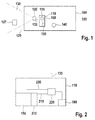
- FIG. 12 shows a block diagram of a vehicle 100 in which a device 110 according to an embodiment of the present invention is used. Furthermore, the vehicle comprises a camera 120 which detects a vehicle environment 125 with an object 127 located therein in a viewing area 130, in particular in front of the vehicle, and a corresponding image 135 on the device 110 for assisting a driver 140 in tracking the vehicle 100 a roadway 145 transmitted.
- the device 110 in this case comprises a display unit 150, on which the camera image 135 can be displayed.
- the display unit 150 contains a touch-sensitive screen, wherein the driver 140 of the vehicle can select an object in the camera image 135 by pressing with his finger on the screen, which is referred to as Basis for the determination of the to be traveled by the vehicle track.
- a central control unit 155 can take over the function of, on the one hand, transmitting the camera image 135 to the display unit 150 and, on the other hand, reading the input from the driver 140 via the touch-sensitive screen.
- a marker can be selected as a marker symbol or marker object and superimposed on that region of the camera image 135 that represents the selected object.
- the image overlaid by the markings is again transmitted to the display unit 150, where it is displayed to the driver 140.
- the marked object can be used as a basis for determining the lane to be traveled by the vehicle, ie the driving lane to be traveled by the vehicle, for example, in a special tracking unit 160 to automatically track this object, ie an automatic lane. and / or transverse guidance of the vehicle or to communicate to the driver 140 signals that give the driver 140 instructions or instructions on how he can lead the vehicle as fast as possible, energy-saving or comfortable in a track defined by the object. Under a "track” is to provide a desired trajectory, which is to drive the vehicle.
- This desired (driving) trajectory can, on the one hand, be a lane marked by lane markings, on the other hand, this trajectory (for example, for non-marked lanes) can be a trajectory calculated by a computer unit in its own vehicle and then output as a "lane" to be traveled , In this way, even when not marked lanes still a "lane” can be obtained, which is to be traveled by the own vehicle to allow the most efficient assistance of the driver in the management of the vehicle.
- the "lane” to be traveled should be determined taking into account the object.
- a "track” is determined on which the object also travels, so that it can be ensured that in determining the trajectory or the following "track” only those trajectories are at all eligible which also relate to the object which should be followed in the present case.
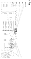
- Fig. 2 shows a more detailed block diagram of a device 110 for assisting the driver in the tracking of a vehicle on a road.
- the device 110 comprises the display unit 150 and a user interface 210, which is embodied, for example, in the form of the touch-sensitive surface of the screen of the display unit 150 or as a microphone for recognizing speech signals and which provides a control signal 215.
- the operating interface may also be located further away from the display unit 150, for example, be formed by a joystick or a touchpad on the center console or by a transverse encoder in the accelerator pedal.
- the device 110 comprises a selection unit 220, which may be arranged in the central control unit 155 and which selects an object contained in the image in response to the operation signal 215 and superimposes a corresponding marking on the camera image 135 in order to obtain a corresponding processed camera image 230.
- the selection unit 220 can also transmit this marker-overlaid camera image 230 back to the display unit 150, on which the camera image 230 is then superimposed.
- the device has the aforementioned tracking unit 160.
- driver assistance systems have in common that they inform the driver little about the object detection by the sensors and that they give him little or no influence, for example, which vehicle to be followed.
- the present invention seeks to remedy this deficiency and describes a driver assistance system that interacts with the driver in a previously unknown manner.
- a driver assistance system that interacts with the driver in a previously unknown manner.
- it uses at least one camera to observe the vehicle surroundings (in particular to the front) and a screen for the presentation of the optionally processed camera image and possible additional information.
- the method according to the invention remedies the lack of system transparency and, in addition, the associated lack of influence possibilities for the driver.
- the basis for this is created by a novel algorithm for video-based object tracking. This allows, among other things, a useful visualization of the object tracking in the video image, which is perceived by the driver as accurate, stable and reliable and thus as high-quality.
- the system presented in this description uses a screen (display) in order to present to the driver at any time the information important to him regarding the driver assistance or the driving task.
- the screen can also be formed by the windshield, then relevant information is displayed on this disc.
- This screen usually displays the image of a camera oriented in the direction of travel.
- This image is further enriched, for example, with information that is interesting or important to the driver.
- the driver is informed according to an embodiment by means of a screen about his choices, which he can make by interacting with the system.
- a "snap-to-object" function to simplify the input:
- the input of the user may be inaccurate, even slightly adjacent to the object.
- the system supports the driver by automatically selecting the object likely to be input. This function further reduces the time required for the input and reduces the time required to view the display.
- the system is in an advantageous embodiment, a feedback to the driver so that he is informed about the new system state.
- the meaningful content of the feedback will often be "object selection ok, the system now follows the selected object!, But it can also be "The system can not handle the tracking!”, Eg. For example, if the driver has made an ambiguous statement or if the system can not find an object at the touched image position that could be followed.
- the confirmation can be made acoustically, z. B. by an acknowledgment tone or a voice prompt, z. B. "The vehicle ahead is now being tracked and the allowed speed of 70 km / h is taken into account.”
- the confirmation can also be haptic, z.
- a short vibration on the steering wheel or at the input interface which is still touched by the driver's hand at this time, or by a vibration of another element (eg foot pedal or seat) which the driver can perceive.
- the signaling will also be optical, z. B. by the display representation changes and thus indicates a mark of the object that has been selected. For example, the question mark shown above would disappear on the fingerprint and only the fingerprint (still "glued" to the object) would remain, as shown in FIGS Figures 3 and 4 is shown.
- phase of object tracking which usually takes a long time, z. For example, until the target object selects a different direction or a different lane than the driver or drives too fast or too slow.
- the display can be used to present to the driver useful or at least interesting additional information relating to the object (of course, also those that are not directly related to the object, such as information about straight valid traffic signs, navigation instructions and the like).
- the drawing of the object can be arbitrarily "enriched”, z. B. with animated graphics, with color highlighting, with numbers and text, with scales and measuring hands and the like.
- the design may focus on aesthetics or information transfer.
- Fig. 5 is such a representation of an object reproduced with additional information. This is an object automatically selected by the system. Therefore, instead of the fingerprint, another symbol, here a pattern 500, is superimposed as a marker. However, it is also conceivable that an object selected by the driver is provided with a marking and at least one additional information and displayed.
- TTC Time to Collision
- T TC time to collision
- T TC detection and approaches to its camera-based determination are described in more detail below, including visual or camera-based determination and discussion of typical driving situations.
- a prediction can be included which either assumes that the current driving state is maintained until the point of collision or which also includes future foreseeable new driving states.
- the T TC described below refers to the time of collision of the object (more precisely: the points observed on the object) with the camera. For the practical application, however, the collision time with the own vehicle front is of interest.
- a camera connected to the ego vehicle tracks two points on the object whose distance is parallel to the camera plane W.
- the scaling factor s approaches + ⁇ . or - ⁇ .
- T TCFront T TCCam - I / v Ego .
- the length I is the distance in the longitudinal direction (direction of travel) between the camera and the vehicle front.
- T TCFront is 0.1 s less than T TCCam .
- This calculation represents a simplification because it does not take into account the velocity of the object V Obi . Since in the considered scenario of the forward drive of the ego vehicle and apart from the reversing of the vehicle in front, the speed of the ego is always greater than the differential speed, the simplification is an estimation of the safe side: The T TC front thus determined is usually slightly lower than the actual T TC .
- the marking that is displayed in the area of the object in the image can be changed over time. For example, according to the Fig. 6 If the system has determined that the time to a collision is only 1.6 seconds, a warning from the driver will be made. In particular, if the longitudinal control is not automatic, but by the driver, it makes sense to warn him of a possible collision. Here, the visual (and possibly acoustic / haptic) warning occurs as soon as a T TC of about 2.0 seconds is exceeded. This time warning threshold is chosen so that the driver still has enough time to react, slow down his vehicle and thus prevent the impending collision. In such a case, for example, a symbol 600 of two colliding vehicles in the area of the object can be superimposed as additional information.
- the visibility of the visual warning and the rapid and correct local detection can be improved if the optical warning pulsates in time, z. B. with a frequency of two to five pulse periods per second, as shown in the FIGS. 7A and 7B is shown, wherein the FIG. 7B a representation of the image with the marker and additional information in a temporal Distance of, for example, 0.2 s as shown in FIG Fig. 7A represents.
- the intensity and size of the color overlay temporally -. B. sinusoidal, sawtooth or rectangular - vary.
- the display is pulsating between a weak and an intensified intensity, as shown here by two snapshots. It is advantageous to choose the pulse amplitude and / or the frequency depending on the T TC , z. B. such that these values continue to increase with increasing risk.
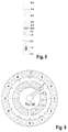
- FIGS. 8 and 9 show a representation of a possible visualization of the TTC in the form of a bar-dia.
- Fig. 9 is the visualization of the TTC in the form shown as a round instrument.
- the "infinity point" (target point) is at the top of the scale.
- T TC ⁇ .
- This ideal point is to be sought by both an automatic distance control (ACC) and a human driver. He is in Fig. 8 marked with "OK" and an asterisk and represents the nominal state. In the lower, darkened area the T TC is positive, ie the collision is imminent. In the deep dark area shown below (about 2s to ⁇ ) a braking intervention is urgently required.
- the T TC range which is not intervening yet, should change with the airspeed.
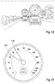
- Fig. 10 shows an embodiment in which one or more T TC tachometers can be faded into the camera image displayed to the driver.
- the T TC tachometer moves as rigidly connected to the respective object and scales depending on its size in the image.
- the system has the opportunity to learn driver preferences (long term and short term).
- driver preferences long term and short term.
- it can adjust to it and use the changed parameters for future control processes.
- a possible embodiment is the semi-automatic control, in which the driver is involved in the control loop.
- the driver continues to operate the throttle and brake and - if available - the gearshift.
- the specifications for their operation are transmitted from the system to the driver. This can be done through visualization as in Fig. 8, Fig. 9 . Fig. 10 or similar.
- Such a semi-automatic system has the advantage that it can be retrofitted without intervention in the vehicle (electronics, mechanics). It is therefore also conceivable in a mobile device that - as today a mobile navigation or mobile phone navigation - is mounted on the windshield or on the dashboard. It is only necessary to ensure that the camera has the best possible unobstructed view to the front.
- the system is able to track several objects at the same time, it may be advantageous to consider them simultaneously in the distance control. This makes sense, for example, if the first target object and the ego vehicle are located on the right highway strip, while the target object overtakes another object on the right. In this case, it makes sense to pursue at least temporarily both target objects and not to overtake the second target object also on the right, in order to avoid a dangerous situation and if necessary to comply with legal requirements.
- Fig. 11 shows an advantageous embodiment for a part of the display in the instrument panel.
- the speedometer is shown, which in addition to the pointer 1110 for the speed of the ego vehicle (light) still has a second pointer 1120 (dark).
- the image of the tracked object is displayed. This can be done within the tachometer instrument or outside at a suitable location.
- the image of the object is obtained by cutting out of the camera image. Due to the video-based object tracking, all the required information is always available (object position and size in the image) in order to make the cutting out correctly.
- the update rate for the image of the tracked object can be selected to be identical to the refresh rate of the camera (eg 25 frames per second) or even different.
- a much lower update rate eg 1 image per second
- a high update rate has the advantage that light signals (brake / turn signals) are reproduced immediately.
- Fig. 12 shows an illustration of how a tracked object can be extracted from a camera image, wherein the approach for extracting in this description should not be further elaborated.
- a temporal filtering takes into account the data of the object tracking.
- the object forms sharp, while the (different moving) background blurred "blurred".
- the object can still be fully displayed even if it is z. B. in tight corners or due to the cover by the own hood of the camera can be detected only partially.
- Fig. 12 shows a typical example: The object automatically shuts itself off out of the blurred background, and the virtual detection area (overall picture) is larger than the camera's coverage area (rectangular white inner frame).
- the system takes into account navigation information and recognizes, as a termination criterion, that the object selects a route other than its own.
- a termination criterion if the tracking of the object would entail that the ego vehicle would have to leave the desired or statutory speed range. Oversteer of gas, brake or possibly steering, the driver can of course also bring about a termination of the object tracking.
- the driver should again be informed visually, acoustically and / or haptically, analogously to the beginning of the object tracking. Subsequently, the system returns to the state where user interaction is required to select the next target object.
- the system can also automatically select the most suitable object for further tracking.
- the degree of this suitability can z. B. depend on which lane the object is located and at what (relative) speed it moves.
- FIG. 12 shows a flow chart of an embodiment of the present invention as method 1300 for assisting a driver in a guidance a vehicle on a roadway.
- the method 1300 includes a step of displaying a read-in image 1310 on a display unit to the driver, the image being captured by a camera and representing a vehicle environment. Further, the method 1300 includes a step of reading in 1320 an operation signal input from the driver on an operation interface, and a step of selecting 1330 an object included in the image using the operation signal. Furthermore, the method 1300 includes a step of displaying 1340 a mark on the display unit, the mark being displayed in a region of the image representing the object. Finally, the method includes a step of using 1350 the object to determine at least one longitudinal control parameter for a travel path to be traveled by the vehicle to assist the driver in tracking the vehicle on the road.
- an exemplary embodiment comprises a "and / or" link between a first feature and a second feature
- this can be read so that the embodiment according to one embodiment, both the first feature and the second feature and according to another embodiment, either only the first Feature or only the second feature.
Landscapes
- Engineering & Computer Science (AREA)
- Mechanical Engineering (AREA)
- Automation & Control Theory (AREA)
- Transportation (AREA)
- Human Computer Interaction (AREA)
- Chemical & Material Sciences (AREA)
- Combustion & Propulsion (AREA)
- Remote Sensing (AREA)
- Radar, Positioning & Navigation (AREA)
- General Physics & Mathematics (AREA)
- Physics & Mathematics (AREA)
- Multimedia (AREA)
- Theoretical Computer Science (AREA)
- Traffic Control Systems (AREA)
- Control Of Driving Devices And Active Controlling Of Vehicle (AREA)
- Instrument Panels (AREA)
Description
Die vorliegende Erfindung bezieht sich auf ein Verfahren zur Unterstützung eines Fahrers bei einer Spurführung eines Fahrzeugs auf einer Fahrbahn, auf eine entsprechende Vorrichtung sowie auf ein entsprechendes Computerprogrammprodukt gemäß den Hauptansprüchen.The present invention relates to a method for assisting a driver in tracking a vehicle on a roadway, to a corresponding device and to a corresponding computer program product according to the main claims.
ACC-Systeme (ACC = Adaptive Cruise Control = adaptive Fahrtsteuerung) regeln den Abstand zu vorausfahrenden Fahrzeugen und befinden sich seit fast 10 Jahren im Markt. Sie basieren meist auf einem Radar-Sensor, in einigen neueren Fahrzeugen auch auf einem Lidar-Sensor. Neuerdings werden auch mehrere Sensoren fusioniert, beispielsweise Radar und Video, um die ACC-Funktion zu verbessern und zu erweitern, beispielsweise in Bezug auf die Berücksichtigung von Spurinformationen, einer Verbesserung der Objektvermessung insbesondere in laterale Richtung, eine frühere Reaktion auf Ein- Ausscherer, eine Freiflächendetektion und Anfahrabsicherung oder eine seitliche Erweiterung des Erfassungsbereichs.ACC (Adaptive Cruise Control) systems regulate the distance to vehicles in front and have been on the market for almost 10 years. They are usually based on a radar sensor, in some newer vehicles also on a lidar sensor. Recently, several sensors have also been merged, such as radar and video, to improve and expand the ACC function, for example with regard to the consideration of lane information, an improvement in object measurement, in particular in a lateral direction, an earlier reaction to single-pulser, one Free-field detection and catch protection or a lateral extension of the detection area.
Die
Allen bisher bekannten Fahrerassistenzsystemen ist gemeinsam, dass sie den Fahrer nur wenig über die Objekterfassung durch die Sensoren informieren.All previously known driver assistance systems have in common that they inform the driver only a little about the object detection by the sensors.
Die
Vor diesem Hintergrund wird mit der vorliegenden Erfindung ein Verfahren, weiterhin ein Steuergerät, das dieses Verfahren verwendet sowie schließlich ein entsprechendes Computerprogrammprodukt gemäß den unabhängigen Patentansprüchen vorgestellt. Vorteilhafte Ausgestaltungen ergeben sich aus den jeweiligen Unteransprüchen und der nachfolgenden Beschreibung.
Die vorliegende Erfindung schafft ein Verfahren zur Unterstützung eines Fahrers bei einer Spurführung eines Fahrzeugs auf einer Fahrbahn, wobei das Verfahren die folgenden Schritte aufweist:
- Anzeigen eines eingelesenen Bildes auf einer Anzeigeeinheit an den Fahrer, wobei das Bild von einer Kamera aufgenommen wurden und eine Fahrzeugumgebung repräsentieren;
- Einlesen eines von dem Fahrer an einer Bedienungsschnittstelle eingegebenen Bedienungssignals;
- Auswählen eines in dem Bild enthaltenen Objektes unter Verwendung des Bedienungssignals;
- Anzeigen einer Markierung auf der Anzeigeeinheit, wobei die Markierung in einem Bereich des Bilds angezeigt wird, der das Objekt repräsentiert; und
- Verwenden des Objektes zur Bestimmung von zumindest einem Längsregelungsparameter für einen von dem Fahrzeug zu befahrenden Fahrweg, um den Fahrer bei der Spurführung des Fahrzeugs auf der Fahrbahn zu unterstützen, insbesondere wobei der zumindest eine Längsregelungsparameter einen einzuhaltenden Abstand des Fahrzeugs zum Objekt und/oder eine relative Geschwindigkeit bei der Annäherung des Fahrzeugs an das Objekt umfasst.
The present invention provides a method of assisting a driver to track a vehicle on a lane, the method comprising the steps of:
- Displaying a scanned image on a display unit to the driver, the image captured by a camera and representing a vehicle environment;
- Reading in an operation signal input from the driver at an operation interface;
- Selecting an object contained in the image using the operation signal;
- Displaying a mark on the display unit, the mark being displayed in an area of the image representing the object; and
- Use of the object for determining at least one longitudinal control parameter for a road to be traveled by the vehicle to assist the driver in the guidance of the vehicle on the road, in particular wherein the at least one longitudinal control parameter a distance of the vehicle to the object and / or a relative Speed at the approach of the vehicle to the object includes.
Die vorliegende Erfindung schafft ferner eine Vorrichtung, insbesondere ein Navigationsgerät, die ausgebildet ist, um die Schritte des erfindungsgemäßen Verfahrens in entsprechenden Einrichtungen durchzuführen bzw. umzusetzen. Auch durch diese Ausführungsvariante der Erfindung in Form einer Vorrichtung kann die der Erfindung zugrunde liegende Aufgabe schnell und effizient gelöst werden.The present invention further provides a device, in particular a navigation device, which is designed to implement or implement the steps of the method according to the invention in corresponding devices. Also this embodiment of the invention in the form of a device, the object underlying the invention can be solved quickly and efficiently.
Unter einer Vorrichtung kann vorliegend ein elektrisches Gerät verstanden werden, das Sensorsignale verarbeitet und in Abhängigkeit davon Steuersignale ausgibt. Die Vorrichtung kann eine Schnittstelle aufweisen, die hard- und/oder softwaremäßig ausgebildet sein kann. Bei einer hardwaremäßigen Ausbildung können die Schnittstellen beispielsweise Teil eines sogenannten System-ASICs sein, der verschiedenste Funktionen der Vorrichtung beinhaltet. Es ist jedoch auch möglich, dass die Schnittstellen eigene, integrierte Schaltkreise sind oder zumindest teilweise aus diskreten Bauelementen bestehen. Bei einer softwaremäßigen Ausbildung können die Schnittstellen Softwaremodule sein, die beispielsweise auf einem Mikrocontroller neben anderen Softwaremodulen vorhanden sind.In the present case, a device can be understood as meaning an electrical device which processes sensor signals and outputs control signals in dependence thereon. The device may have an interface, which may be formed in hardware and / or software. In the case of a hardware-based embodiment, the interfaces can be part of a so-called system ASIC, for example, which contains a wide variety of functions of the device. However, it is also possible that the interfaces are their own integrated circuits or at least partially consist of discrete components. In a software training, the interfaces may be software modules that are present, for example, on a microcontroller in addition to other software modules.
Von Vorteil ist auch ein Computerprogrammprodukt mit Programmcode, der auf einem maschinenlesbaren Träger wie einem Halbleiterspeicher, einem Festplattenspeicher oder einem optischen Speicher gespeichert sein kann und zur Durchführung des Verfahrens nach einer der vorstehend beschriebenen Ausführungsformen verwendet wird, wenn das Programm auf einem, einem Computer entsprechenden Gerät ausgeführt wird.A computer program product with program code which can be stored on a machine-readable carrier such as a semiconductor memory, a hard disk memory or an optical memory and is used to carry out the method according to one of the embodiments described above if the program is on a computer corresponding to a computer is also of advantage Device is running.
Unter einer Unterstützung eines Fahrers bei der Spurführung eines Fahrzeugs auf einer Fahrbahn ist beispielsweise eine automatische Längsregelung und/oder eine Querführung bezüglich des Objektes zu verstehen oder auch eine Unterstützung in Form von akustischer und/oder haptischer und/oder virtueller Signale an den Fahrer zu verstehen, die zum Bremsen und Beschleunigen oder Lenken auffordern. Mit einer Anzeigeeinheit kann ein Bildschirm oder auch eine Einrichtung verstanden werden, die Objekte auf die Windschutzscheibe projiziert. Unter einer Fahrzeugumgebung kann ein Außenbereich um das Fahrzeug verstanden werden, insbesondere eine Fahrbahn vor dem Fahrzeug, die von der Kamera aufgenommen wird. Unter einer Bedienungsschnittstelle kann eine Schnittstelle verstanden werden, die eine manuelle, sprachliche oder andere Eingabe eines Fahrers oder einer Person in dem Fahrzeug erkennt, welche hierauf ansprechend das Bedienungssignal bereitstellt. Unter einer Markierung kann ein Markierungsobjekt verstanden werden, welches auf der Anzeigeeinheit angezeigt wird. Dabei kann die Markierung beziehungsweise das Markierungsobjekt einem Bereich des Bildes überlagert werden, in dem auch das Objekt dargestellt wird, welches ausgewählt wurde. Unter einer Bestimmung eines von dem Fahrzeug zu befahrenden Fahrerweges kann eine Ermittlung denjenigen Trajektorie verstanden werden, die das Fahrzeug günstigerweise geführt werden soll, um beispielsweise dem Objekt auf dem kürzesten Weg oder dem komfortabelsten Weise zu folgen. Unter einem Längsregelungsparameter kann beispielsweise ein Abstand zu einem Objekt, dem das Fahrzeug folgen soll oder eine Geschwindigkeit verstanden werden, wobei diese Geschwindigkeit eine maximale Geschwindigkeit darstellt, die das Fahrzeug einhalten soll, damit eine Kollision mit dem Objekt vermieden werden kann. Dieser Längsregelungsparameter kann dann in einer Fahrzeugführungsassistenzeinheit verwendet werden, um ein Längsführungssignal zu generieren und dem Fahrer auszugeben, um ihn durch dieses Längsführungssignal bei der Steuerung des Fahrzeugs zu unterstützen. Unter einem Längsführungssignal kann dabei ein Signal verstanden werden, das eine Anzeige für den Fahrer bietet, wie groß die Entfernung oder wie groß die Geschwindigkeit in Bezug auf einen möglichen Zusammenprall des Fahrzeugs mit dem Objekt ist. Beispielsweise kann das Längsführungssignal in der Form eines Tachometers dargestellt werden, bei dem die Gefahr eines in Kürze zu befürchtenden Zusammenpralls des Fahrzeugs mit dem Objekt bildlich dargestellt ist. Alternativ oder zusätzlich kann natürlich das Längsführungssignal auch verwendet werden, um automatisch einen Lenkungseingriff vorzunehmen und/oder eine Bremse zu aktivieren, um dem Fahrer des Fahrzeugs zu assistieren.An assistance of a driver in the tracking of a vehicle on a roadway is to be understood as meaning, for example, an automatic longitudinal regulation and / or a lateral guidance with respect to the object or also an assistance in the form of acoustic and / or haptic and / or virtual signals to the driver which call for braking and accelerating or steering. A display unit can be understood as a screen or a device which projects objects onto the windshield. A vehicle environment may be understood to mean an outside area around the vehicle, in particular a roadway in front of the vehicle, which is picked up by the camera. An operator interface may be understood to mean an interface that recognizes a manual, verbal or other input of a driver or a person in the vehicle, which responsively provides the operator signal. A marking can be understood as a marking object which is displayed on the display unit becomes. In this case, the marking or the marking object can be superimposed on a region of the image in which the object which was selected is also displayed. By determining a driver's route to be traveled by the vehicle, a determination can be made of the trajectory that the vehicle is to be favorably guided in order, for example, to follow the object in the shortest path or in the most comfortable manner. By a longitudinal control parameter, for example, a distance to an object to be followed by the vehicle or a speed can be understood, this speed representing a maximum speed which the vehicle is to observe in order to avoid a collision with the object. This longitudinal control parameter may then be used in a vehicle guidance assistance unit to generate and output a longitudinal guidance signal to the driver to assist in steering the vehicle by this longitudinal guidance signal. A longitudinal guidance signal may be understood to be a signal which provides an indication to the driver, how great the distance or how great the speed is in relation to a possible collision of the vehicle with the object. For example, the longitudinal guidance signal can be represented in the form of a speedometer, in which the risk of a collision of the vehicle to be feared in the near future with the object is depicted. Alternatively or additionally, of course, the longitudinal guidance signal can also be used to automatically make a steering intervention and / or to activate a brake to assist the driver of the vehicle.
Die vorliegende Erfindung basiert auf der Erkenntnis, dass nun durch des Anzeigen der Markierung auf der Anzeigeeinheit und dem Verwenden sowie der Bestimmung eines von dem Fahrzeug zu fahrenden Fahrwegs der Fahrer des Fahrzeugs auf optische sehr ansprechende und einfach zu erkennen Weise eine Information erhält, welches Objekt das Navigationsgerät bei der Bestimmung der Spurführung zu Grunde legt. Hierdurch kann der Fahrer schnell einen Fehler erkennen, wenn beispielsweise ein nicht gewünschtes Objekt zur Bestimmung von zumindest einem Längsregelungsparameter für einen vom Fahrzeug zu befahrenden Fahrweg verwendet wird. Beispielsweise kann sich ein solcher Längsregelungsparameter auch auf eine Geschwindigkeit beziehen, mit der sich die Objekte bewegen. Wenn beispielsweise rechts auf einer Fahrbahn und ein langsames und links auf der (Nachbar-) Fahrbahn ein schnelles Fahrzeug fahren, kann wegen der Geschwindigkeit das linke Fahrzeug ausgewählt werden und dem System damit mitgeteilt werden, dass der Fahrer nicht verlangsamen und dem rechten Fahrzeug folgen, sondern schnell fahren will. Auf diese Weise können Irritationen des Fahrers vermieden werden, die möglicherweise gefährliche Situationen im Straßenverkehr durch eine Ablenkung des Fahrers verursachen.The present invention is based on the recognition that now, by displaying the marking on the display unit and using and determining a driving path to be traveled by the vehicle, the driver of the vehicle obtains information in an optical, very appealing and easily recognizable manner, which object the navigation device is used as a basis for determining the guidance. As a result, the driver can quickly detect a fault, for example, if an undesired object is used to determine at least one longitudinal control parameter for a travel path to be traveled by the vehicle. For example, such a longitudinal control parameter may also refer to a speed at which the objects move. For example, if driving a fast vehicle on the right and a slow one on the left and on the (neighboring) road on the left can Because of the speed, the left vehicle will be selected and the system will be told that the driver does not want to slow down and follow the right vehicle but wants to drive fast. In this way, irritation of the driver can be avoided, possibly causing dangerous situations in the road by a distraction of the driver.
Günstig ist es, wenn gemäß einer besonderen Ausführungsform der vorliegenden Erfindung im Schritt des Anzeigens des Bildes eine Voraberkennung von Objekten aus dem Bild erfolgt, wobei im Schritt des Auswählens unter Verwendung des Bedienungssignals eines von mehreren voraberkannten Objekten ausgewählt wird. Unter einer Voraberkennung kann eine Vorauswertung verstanden werden, bei der das Bild bereits vor dem Auswählen eines Objektes untersucht wird und mehrere mögliche auszuwählende Objekte bereits erkannt oder als solche klassifiziert werden. Eine derartige Ausführungsform der vorliegenden Erfindung bietet den Vorteil, dass nun das Auswählen und nachfolgend das Markieren des ausgewählten Objekts schneller erfolgen kann, wodurch der Fahrer eine kürzere Zeitspanne seinen Blick auf die Anzeigeeinheit richten braucht, um zu erkennen, ob das richtige Objekt für die Bestimmung des Fahrwegs ausgewählt wurde.It is advantageous if according to a particular embodiment of the present invention, in the step of displaying the image, a pre-recognition of objects from the image takes place, wherein in the step of selecting using the operating signal one of a plurality of pre-recognized objects is selected. A pre-recognition can be understood as a pre-evaluation in which the image is examined before the selection of an object and several possible objects to be selected are already recognized or classified as such. Such an embodiment of the present invention has the advantage that now the selection and subsequently the marking of the selected object can be made faster, whereby the driver needs to focus his eyes on the display unit for a shorter period of time to see if the correct object for the determination the route was selected.
Gemäß einer weiteren Ausführungsform der vorliegenden Erfindung kann im Schritt des Anzeigens das Bild auf einem berührungsempfindlichen Display der Anzeigeeinheit angezeigt werden und wobei im Schritt des Einlesens ein erkannter Druck auf das berührungsempfindliche Display als Bedienungssignal eingelesen wird. Eine derartige Ausführungsform der vorliegenden Erfindung bietet den Vorteil einer schnellen, präzisen und zuverlässigen Möglichkeit zur Auswahl eines Objektes durch den Fahrer, welches zur Bestimmung des zu befahrenden Fahrwegs verwendet werden soll.According to another embodiment of the present invention, in the step of displaying, the image may be displayed on a touch-sensitive display of the display unit, and in the reading-in step, a detected pressure on the touch-sensitive display is read as an operation signal. Such an embodiment of the present invention provides the advantage of a quick, accurate and reliable way of selecting an object by the driver to be used to determine the route to travel.
Alternativ kann auch im Schritt des Einlesens das Bedienungssignal ansprechend auf eine erkannte Geste des Fahrers, insbesondere ein Zeigen des Fahrers mit dem Finger auf eine Position generiert werden. Eine derartige Ausführungsform der vorliegenden Erfindung bietet eine weitere Komfortsteigerung für den Fahrer, da er bei der Eingabe nicht mehr darauf achten braucht, ob er auch ein berührungsempfindliches Display an der korrekten Stelle berührt. Insofern kann auch die Sicherheit des Fahrers erhöht werden, da der Fahrer seine Aufmerksamkeit nicht mehr so lange von dem Verkehrsgeschehen abwenden braucht, um die entsprechende Eingabe zu tätigen.Alternatively, also in the step of reading the operating signal in response to a detected gesture of the driver, in particular a pointing of the driver with a finger to a position can be generated. Such an embodiment of the present invention provides a further increase in comfort for the driver, as he no longer needs to pay attention to whether he also touches a touch-sensitive display at the correct location. In this respect, the driver's safety can also be increased because the driver's attention no longer need to turn away from the traffic so long to make the appropriate input.
Um auch eine präzise Auswahl des gewünschten Objektes bei der Fahrt im Fahrzeug zu ermöglichen, kann im Schritt des Auswählens dasjenige in dem Bild voraberkannte Objekt ausgewählt werden, das am Nähesten zu einer Position in dem Bild liegt, die durch einen erkannten Druck auf das berührungsempfindliche Display repräsentiert ist. Eine solche Funktion bietet beispielsweise auch bei unpräzisen Eingaben auf dem berührungsempfindlichen Display die Möglichkeit dennoch das gewünschte Objekt zuverlässig auswählen zu können. Insbesondere ist eine solche Möglichkeit beispielsweise bei einer Fahrt auf unebener Fahrbahn oder bei einem lediglich kurzen Blick auf die Anzeigeeinheit bei einer schnellen Fahrt auf der Autobahn von besonderem Vorteil.In order to also allow a precise selection of the desired object when driving in the vehicle, in the step of selecting, that in the image pre-recognized object that is closest to a position in the image, by a detected pressure on the touch-sensitive display is represented. Such a function offers, for example, even with imprecise inputs on the touch-sensitive display the ability to select the desired object reliably. In particular, such a possibility, for example, when driving on uneven road surface or a mere glance at the display unit in a fast ride on the highway of particular advantage.
Besonders vorteilhaft ist es, wenn gemäß einer weiteren Ausführungsform der vorliegenden Erfindung im Schritt des Einlesens eine Bedienungsschnittstelle verwendet wird, die das Bedienungssignal durch eine Auswertung eines Sprachbefehls des Fahrers des Fahrzeugs erzeugt. Eine derartige Ausführungsform der vorliegenden Erfindung bietet den Vorteil einer Eingabe durch den Fahrer, ohne dass dieser beispielsweise die Hand von Fahrzeugsteuerungseinheiten wie dem Lenkrad oder einem Gangschalthebel entfernen braucht. Dies erhöht die Verkehrssicherheit beim Einsatz des hier vorgeschlagenen Ansatzes.It is particularly advantageous if, in accordance with a further embodiment of the present invention, an operating interface which generates the operating signal by an evaluation of a voice command of the driver of the vehicle is used in the reading-in step. Such an embodiment of the present invention has the advantage of being input by the driver without, for example, having to remove the hand from vehicle control units such as the steering wheel or a gearshift lever. This increases traffic safety when using the approach proposed here.
Gemäß einer anderen Ausführungsform der vorliegenden Erfindung kann im Schritt des Auswählens des Objektes ein Objekt ausgewählt werden, das ein anderes Fahrzeug repräsentiert, das sich auf der Fahrbahn vor oder neben dem Fahrzeug befindet. Eine derartige Ausführungsform der vorliegenden Erfindung bietet den Vorteil einer einfachen Auswahl eines Fahrzeugs, dem mit einem Spurführungsassistenten gefolgt werden soll. Weiterhin ist ein anderes Fahrzeug meist auch ausreichend groß, um einerseits über einen Tastendruck schnell ausgewählt werden zu können oder andererseits auf der Anzeigeeinheit schnell erkannt zu werden, so dass der Fahrer nur eine sehr kleine Zeitspanne seinen Blick vom Verkehrsgeschehen auf die Anzeigeeinheit zu richten braucht.According to another embodiment of the present invention, in the step of selecting the object, an object representing another vehicle located on the lane in front of or beside the vehicle may be selected. Such an embodiment of the present invention offers the advantage of easy selection of a vehicle to be followed with a guidance assistant. Furthermore, another vehicle is usually also sufficiently large to be able to be quickly selected on the one hand by pressing a button or on the other to be quickly recognized on the display unit, so that the driver only needs to direct his eyes from the traffic to the display unit for a very short period of time.
Weiterhin kann gemäß einer anderen Ausführungsform der vorliegenden Erfindung im Schritt des Anzeigens die Markierung mit zeitlich variierender Darstellung angezeigt werden. Eine derartige Ausführungsform der vorliegenden Erfindung bietet den Vorteil, dass das ausgewählte Objekt sehr schnell, auch bei einem nur flüchtigen Blick auf die Anzeigeeinheit erkannt werden kann. Ferner können durch die Variation der Darstellung zusätzliche Informationen wie beispielsweise ein Hinweis auf eine drohende Kollision mit dem zu verfolgenden Objekt angezeigt werden. Hierdurch wird ebenfalls wieder die Verkehrssicherheit erhöht, da die Aufmerksamkeit des Fahrers nur für eine geringe Zeitspanne vom Verkehrsgeschehen abgewendet werden braucht.Furthermore, according to another embodiment of the present invention, in the step of displaying, the mark may vary in time are displayed. Such an embodiment of the present invention offers the advantage that the selected object can be detected very quickly, even with only a glance at the display unit. Further, by the variation of the representation additional information such as an indication of an imminent collision with the object to be tracked can be displayed. As a result, the traffic safety is also increased again, since the driver's attention needs to be averted from the traffic for a small period of time.
Um beispielsweise eine in Kürze zu erwartende gefährliche Situation im Zusammenhang mit dem Objekt dem Fahrer möglichst frühzeitig und schnell übermitteln zu können, kann im Schritt des Anzeigens ferner eine Information bezüglich eines Abstands zu dem Objekt auf der Anzeigeeinheit angezeigt werden, wobei die Information in einem Bereich des Bildes angezeigt wird, der das Objekt repräsentiert. Unter einer solchen Information kann beispielsweise ein Hinweis auf einen kurz bevorstehenden Zusammenstoß mit dem Objekt angezeigt werden. In diesem Fall kann beispielsweise die Information als Symbol oder spezielle Grafik zusammen mit der Markierung in demjenigen Bereich des Bildes angezeigt werden, der das Objekt repräsentiert.For example, in order to be able to transmit to the driver as soon as possible and quickly a dangerous situation to be expected in connection with the object, information about a distance to the object on the display unit can also be displayed in the step of the display, the information being in one area the image that represents the object. Under such information, for example, an indication of an imminent collision with the object may be displayed. In this case, for example, the information may be displayed as a symbol or special graphic along with the mark in the area of the image representing the object.
Gemäß einer weiteren Ausführungsform der vorliegenden Erfindung kann auch im Schritt des Verwendens ferner ein Vergleich des Fahrweges des Objektes mit einer gewünschten vordefinierten Fahrstrecke des Fahrzeugs erfolgen, wobei das Objekt nicht mehr zur Bestimmung des von dem Fahrzeug zu befahrenden Fahrweges verwendet wird, wenn der Vergleich ergeben hat, dass das Objekt sich mehr als eine vorbestimmte Distanz von der gewünschten vordefinierten Fahrstrecke weg entfernt hat und/oder
dass im Schritt des Verwendens das Objekt nicht mehr zur Bestimmung des von dem Fahrzeug zu befahrenden Fahrweges verwendet wird, wenn eine bestimmte Geschwindigkeit des Objektes größer als eine an der Position des Fahrzeugs zulässige Geschwindigkeit ist und/oder
dass im Schritt des Verwendens das Objekt nicht mehr zur Bestimmung von zumindest einem Längsregelungsparameter für einen von dem Fahrzeug zu befahrenden Fahrweges verwendet wird, wenn ein ermittelter Abstand des Objektes zu dem Fahrzeug größer als ein vorbestimmter Abstand ist. Eine derartige Ausführungsform der vorliegenden Erfindung bietet den Vorteil, dass frühzeitig erkannt werden kann, dass sich das Objekt, welches als Basis für die Bestimmung des zu befahrenden Fahrwegs verwendet wird, insbesondere welche ihm gefolgt wird, nicht mehr als solches die Spurführung des eigenen Fahrzeugs unterstützendes Objekt eignet. In diesem Fall kann die Ausgabe einer Fehlermeldung vermieden werden, die möglicherweise den Fahrer irritieren würde und somit zu einer gefährlichen Verkehrssituation führen könnte.According to a further embodiment of the present invention, in the step of using, a comparison of the travel path of the object with a desired predefined driving distance of the vehicle can also be carried out, wherein the object is no longer used to determine the travel path to be traveled by the vehicle when the comparison results has that the object has been away more than a predetermined distance away from the desired predefined route and / or
in the step of using, the object is no longer used for determining the travel path to be traveled by the vehicle, if a specific speed of the object is greater than a speed permissible at the position of the vehicle, and / or
that in the step of using the object is no longer used for determining at least one longitudinal control parameter for a travel path to be traveled by the vehicle when a determined distance of the object to the vehicle is greater than a predetermined distance. Such an embodiment of the present invention offers the advantage of being recognized early It can be that the object which is used as the basis for the determination of the driving route to be traveled, in particular which is followed, no longer suitable as such the tracking of the own vehicle supporting object. In this case, issuing an error message that could possibly irritate the driver and thus lead to a dangerous traffic situation can be avoided.
Die Erfindung wird nachstehend anhand der beigefügten Zeichnungen beispielhaft näher erläutert. Es zeigen:
- Fig. 1
- ein Blockschaltbild eines Fahrzeugs, in dem eine Vorrichtung gemäß einem Ausführungsbeispiel der vorliegenden Erfindung verwendet wird;
- Fig. 2
- ein detaillierteres Blockschaltbild einer Vorrichtung zur Unterstützung des Fahrers bei der Spurführung eines Fahrzeugs auf einer Fahrbahn aus
Fig. 1 ; - Fig. 3
- eine Darstellung eines von der Kamera des Fahrzeugs aufgenommenen Bildes;
- Fig. 4
- eine weitere Darstellung eines von der Kamera des Fahrzeugs aufgenommenen Bildes, wobei eine Markierung in demjenigen Bereich eingeblendet ist, an dem sich das ausgewählte Objekt im Kamerabild befindet;
- Fig. 5
- eine Darstellung eines Objektes mit einer Markierung oder einer Zusatzinformation in einem Kamerabild;
- Fig. 6
- eine weitere Darstellung eines Objektes mit Markierung oder einer Zusatzinformation in einem Kamerabild;
- Fig. 7A-7B
- Darstellungen des Objektes mit einer Zusatzinformation in dem Kamerabild zu unterschiedlichen Zeitpunkten;
- Fig. 8
- eine Darstellung einer Visualisierung der Zeit bis zu einer Kollision mit einem Objekt in einem Balkendiagramm;
- Fig. 9
- eine Darstellung einer Visualisierung der Zeit bis zu einer Kollision mit einem Objekt in der Form eines Rundinstrumentes;
- Fig. 10
- eine Darstellung der Einblendung von Zeiten bis zu einer Kollision mit verschiedenen Objekten in der Form von Rundinstrumenten, die im Bereich der jeweiligen Objekte im Kamerabild eingeblendet sind;
- Fig. 11
- eine Darstellung der Einblendung von Geschwindigkeiten des eigenen Fahrzeugs und eines weiteren Fahrzeugs in einem gemeinsamen Rundinstrument;
- Fig. 12
- eine Darstellung eines Kamerabildes, das eine Extraktion eines verfolgten Objektes aus dem Bild ermöglicht; und
- Fig. 13
- ein Ablaufdiagramm eines Verfahrens gemäß einem Ausführungsbeispiel der vorliegenden Erfindung.
- Fig. 1
- a block diagram of a vehicle in which a device according to an embodiment of the present invention is used;
- Fig. 2
- a more detailed block diagram of a device for assisting the driver in the tracking of a vehicle on a road surface
Fig. 1 ; - Fig. 3
- a representation of an image taken by the camera of the vehicle image;
- Fig. 4
- a further representation of an image taken by the camera of the vehicle, wherein a mark is faded in the area where the selected object is in the camera image;
- Fig. 5
- a representation of an object with a marker or additional information in a camera image;
- Fig. 6
- a further representation of an object with marking or additional information in a camera image;
- Figs. 7A-7B
- Representations of the object with additional information in the camera image at different times;
- Fig. 8
- a representation of a visualization of the time to a collision with an object in a bar chart;
- Fig. 9
- a representation of a visualization of the time to a collision with an object in the form of a round instrument;
- Fig. 10
- a representation of the display of times to a collision with various objects in the form of round instruments, which are displayed in the area of the respective objects in the camera image;
- Fig. 11
- a representation of the display of speeds of the own vehicle and another vehicle in a common round instrument;
- Fig. 12
- a representation of a camera image that allows extraction of a tracked object from the image; and
- Fig. 13
- a flowchart of a method according to an embodiment of the present invention.
In der nachfolgenden Beschreibung bevorzugter Ausführungsbeispiele der vorliegenden Erfindung werden für die in den verschiedenen Figuren dargestellten und ähnlich wirkenden Elemente gleiche oder ähnliche Bezugszeichen verwendet, wobei auf eine wiederholte Beschreibung dieser Elemente verzichtet wird.In the following description of preferred embodiments of the present invention, the same or similar reference numerals are used for the elements shown in the various figures and similarly acting, wherein a repeated description of these elements is omitted.
Allen bisher bekannten Fahrerassistenzsystemen ist gemeinsam, dass sie den Fahrer nur wenig über die Objekterfassung durch die Sensoren informieren und dass sie ihm wenig oder gar keine Einflussmöglichkeiten geben, beispielsweise welchem Fahrzeug gefolgt werden soll.All previously known driver assistance systems have in common that they inform the driver little about the object detection by the sensors and that they give him little or no influence, for example, which vehicle to be followed.
Die vorliegende Erfindung strebt insbesondere an, diesen Mangel zu beheben und beschreibt ein Fahrerassistenzsystem, das auf bisher nicht bekannte Weise mit dem Fahrer interagiert. Dazu nutzt es mindestens eine Kamera zur Beobachtung des Fahrzeugumfelds (insbesondere nach vorne) und einen Bildschirm zur Darbietung des gegebenenfalls aufbereiteten Kamerabilds und möglichen Zusatzinformationen.In particular, the present invention seeks to remedy this deficiency and describes a driver assistance system that interacts with the driver in a previously unknown manner. For this purpose, it uses at least one camera to observe the vehicle surroundings (in particular to the front) and a screen for the presentation of the optionally processed camera image and possible additional information.
Als Grund für die Unzufriedenheit mit ihren Fahrerassistenzsystemen geben Kunden häufig an, dass ihnen das Verhalten des Systems des Öfteren nicht plausibel ist. Es mangelt an der Nachvollziehbarkeit, warum sich das System gerade so verhält. Dies trifft insbesondere dann zu, wenn sich das Systemverhalten deutlich von dem vom Fahrer in diesem Moment erwarteten oder bevorzugten Verhalten unterscheidet.As a reason for dissatisfaction with their driver assistance systems, customers often state that the behavior of the system is often implausible. There is a lack of comprehensibility as to why the system is acting like this. This is especially true if the system behavior differs significantly from the behavior expected or preferred by the driver at that moment.
Eine Ursache für diesen Mangel liegt in Schwächen der Sensoren begründet (z. B. mangelnde Reichweite bei sehr schneller Autobahnfahrt, zu späte Erfassung von relevanten Einscherern, Auftreten von Scheinobjekten). Das erfindungsgemäße Verfahren behebt den Mangel an Systemtransparenz und desweiteren den damit verbundenen Mangel an Einflussmöglichkeiten für den Fahrer. Die Grundlage hierfür schafft ein neuartiger Algorithmus zur videobasierten Objektverfolgung. Dieser ermöglicht u. a. eine nützliche Visualisierung der Objektverfolgung im Videobild, die vom Fahrer als exakt, stabil und zuverlässig und damit als hochwertig wahrgenommen wird.One of the reasons for this deficiency is the weaknesses of the sensors (eg lack of range with very fast motorway driving, too late detection) of relevant Einscherern, appearance of false objects). The method according to the invention remedies the lack of system transparency and, in addition, the associated lack of influence possibilities for the driver. The basis for this is created by a novel algorithm for video-based object tracking. This allows, among other things, a useful visualization of the object tracking in the video image, which is perceived by the driver as accurate, stable and reliable and thus as high-quality.
Das in dieser Beschreibung vorgestellte System verwendet einen Bildschirm (Display), um dem Fahrer zu jedem Zeitpunkt die für ihn wichtigen Informationen bezüglich der Fahrerassistenz bzw. der Fahraufgabe darzustellen. Der Bildschirm kann auch durch die Windschutzscheibe gebildet werden, wobei dann relevante Informationen auf diese Scheibe eingeblendet werden.The system presented in this description uses a screen (display) in order to present to the driver at any time the information important to him regarding the driver assistance or the driving task. The screen can also be formed by the windshield, then relevant information is displayed on this disc.
Auf diesem Bildschirm wird gewöhnlich das Bild einer in Fahrtrichtung orientierten Kamera angezeigt. Dieses Bild wird beispielsweise ferner angereichert mit Informationen, die für den Fahrer interessant oder wichtig sind. Weiterhin wird der Fahrer gemäß einem Ausführungsbeispiel mittels Bildschirm über seine Auswahlmöglichkeiten informiert, die er per Interaktion mit dem System treffen kann.This screen usually displays the image of a camera oriented in the direction of travel. This image is further enriched, for example, with information that is interesting or important to the driver. Furthermore, the driver is informed according to an embodiment by means of a screen about his choices, which he can make by interacting with the system.
Zusatzinformationen des Systems, die andere Objekte, z. B. Fahrzeuge, betreffen, werden im Bild fest mit dem Objekt verbunden, sie wirken sozusagen scheinbar an das Objekt "angeklebt". Die nachfolgende Systembeschreibung basiert also insbesondere auf den Fähigkeiten eines Algorithmus, der solche Objektinformationen zusammen mit einem Objekt darstellt, wobei ein solcher Algorithmus eine wichtige Voraussetzung für die praktische Umsetzbarkeit der Erfindung schafft.Additional information of the system, the other objects, such. As vehicles, are in the image firmly connected to the object, they seem to seem to the object "glued". The following system description is therefore based in particular on the capabilities of an algorithm which represents such object information together with an object, such an algorithm providing an important prerequisite for the practical implementation of the invention.
Die Funktionsweise der hier in einem Ausführungsbeispiel beschriebenen Erfindung basiert auf Daten von zumindest einem Umfeldsensor (bevorzugt Video, alternativ Range-Video (Lichtlaufzeitmessung), Radar, Lidar, Ultraschall oder Kombinationen davon). Diese Daten betreffen
- insbesondere die Längsregelung des Egofahrzeugs (d.h. des eigenen Fahrzeugs, in dem der Fahrer sitzt), gegebenenfalls auch die Querregelung und/oder
- eine Ausgabe von Fahranweisungen, die den Fahrer bei der Aufgabe der Längs-/Querregelung unterstützen.
- in particular the longitudinal regulation of the ego vehicle (ie the own vehicle in which the driver sits), possibly also the transverse control and / or
- an output of driving instructions that assist the driver in the task of longitudinal / lateral control.
Das System gemäß dem Ausführungsbeispiel der Erfindung wird nachfolgend anhand der Phasen einer Objektverfolgung näher beschrieben. Zwischendurch werden Ausgestaltungsvarianten diskutiert.The system according to the embodiment of the invention will be described in more detail below with reference to the phases of an object tracking. In between, design variants are discussed.
Das System kann (wahlweise oder je nach Verfügbarkeit einer Objektdetektion) mit oder ohne automatische Objektdetektion betrieben werden:
- Falls keine Objektdetektion vorhanden ist oder falls sie nicht verwendet wird, kann der Fahrer die Objektauswahl selbst vornehmen. Dazu berührt er mit beispielsweise einem Finger auf dem berührungsempfindlichen Display (Touchscreen) dasjenige angezeigte Objekt, dem er folgen will.
Dazu sollte sich der Touchscreen an einer geeigneten Stelle befinden, so dass die Berührung mit einem Finger leicht möglich ist. Eine Positionierung hinter dem Lenkrad wäre hier weniger günstig.
Alternativ können Display und Eingabeelement auch baulich getrennt sein. Beispielsweise kann das Eingabeelement ähnlich einem PC-Grafiktablett oder ähnlich einem Touchpad von Notebook-PCs ausgeführt sein und sich auf der Mittelkonsole oder am Lenkrad oder an einer sonstigen für den Fahrer leicht erreichbaren Stelle befinden.
Nachdem der Fahrer das Objekt z. B. durch Antippen mit dem Finger ausgewählt hat, beginnt ein Objekt-Tracking-Algorithmus die Verfolgung. Dabei werden (beispielsweise mit dem "AnyTrack"-Algorithmus von Bosch) gleichzeitig die Objektbewegung im Bild, die Größenveränderung (Skalierung) im Bild und die Objektabmessungen im Bild bestimmt. Hierdurch wird es möglich, eine Zusatzinformation (d.h. eine Markierung) in das Bild (insbesondere im Bereich des zu verfolgenden Objektes) einzublenden, die die richtige Größe besitzt und die ermittelten Bewegungs- und Skalierungsdaten verwendet.
Diese Zusatzinformation kann im einfachsten Fall aus einem an sich unveränderlichen (aber mitbewegten und mitskalierten) Bild als Markierung bestehen, z. B. aus dem Bild eines Fingerabdrucks. Dieses Bild des Fingerabdrucks erscheint dann wie angeklebt an das Fahrzeug.
Fig. 3 zeigt eine Darstellung eines solchen von der Kamera des Fahrzeugs aufgenommenen Bildes, wobei ein mögliches zu verfolgendes Objekt 300 auf einer Fahrspur für den Geradeaus-Verkehr bereits erkannt wurde und zur Auswahl mit einem Fragezeichen vormarkiert wird. Durch das Anzeigen eines Fragezeichens und des Abbilds eines Fingerabdrucks auf dem Objekt 300 wird dem Fahrer somit angeboten, die automatische Längs- und ggf. Querführung bezüglich dieses Zielobjekts zu starten. Durch einen Fingerdruck auf den berührungsempfindlichen Bildschirm nimmt der Fahrer das Angebot an. Auf der rechten Seite der Darstellung ist eine Skala aufgetragen, in der eine Zeitspanne eingetragen ist, die bei konstant bleibender aktueller Geschwindigkeit noch vergehen würde, bis das Fahrzeug mit dem gewählten bzw. markierten Objekt kollidieren würde. Wählt der Fahrer des Fahrzeugs dieses Objekt aus, wird das Fragezeichen als Vormarkierung entfernt undein Fingerabdruck 310 als Markierung des ausgewählten Objektes 310 dem Kamerabild überlagert und auf der Anzeigeeinheit dargestellt, so dass auf einem Bildschirm der Anzeigeeinheit eine Darstellung gemäß derFig. 4 abgebildet wird. Nach der Bestätigung des Zielobjekts durch den Fahrer wird somit das Fragezeichen nicht mehr angezeigt. Der weiterhin dauerhaft sichtbare und fest mit dem Zielobjekt verbundene Fingerabdruck gibt dem Fahrer zu erkennen und bestätigt ihm, dass sich die Längs- und gegebenenfalls Querführung auf das von ihm zuvor per Fingerberührung ausgewählte Fahrzeug bezieht. Eine Farbe der Darstellung des Fingerabdrucks (als Markierung) kann gemäß einer vorbestimmten Farbskala gewählt werden, die nachfolgend noch erläutert wird. Die Farbe korrespondiert beispielsweise zur verbleibenden Zeit bis zur Kollision und stellt somit eine Korrespondenz zur die Dringlichkeit des (Brems-)Eingriffs her. Tiefrot kann beispielsweise einen "besonders dringenden" erforderlichen Bremseingriff durch den Fahrer erfordern. - Falls ein Detektionsalgorithmus vorhanden ist, der bereits selbstständig das oder die relevante(n) Objekt(e) detektiert hat, können diese dem Fahrer zur
Auswahl bzw. zur Bestätigung angeboten werden. Dies erfolgt durch eine geeignete visuelle Darstellung im Display, z. B. indem das/die Objekt(e) hervorgehoben werden und zusammen mit dem jeweiligen Objekt ein Symbol angezeigt wird, das dem Fahrer anzeigt, dass er eine Wahlmöglichkeit hat bzw. das eine Bestätigung von ihm erwartet wird.
Im einfachsten Falle wird auch hier wieder ein unveränderliches (aber mitbewegtes, mitskaliertes) Bild verwendet, zum Beispiel das Bild eines Fingerabdrucks mit einem Fragezeichen. Das Bildsymbol sollte so gewählt sein, dass auch dem mit dem System unerfahrenen Fahrer möglichst schnell und unmissverständlich klar wird, dass von ihm eine Eingabe auf bestimmte Weise erwartet wird, hier z. B. der Druck mit dem Finger auf das Display.
Durch den Fingerdruck wählt der Fahrer eines von ggf. mehreren Objekten aus. Die Verfolgung dieses "Zielobjekts" beginnt.
Das bedeutet, dass fortan z. B. eine automatisch Längsregelung und/oder eine Querführung bezüglich des Objekts durchgeführt wird oder aber dass der Fahrer bei der Fahrzeugführung Unterstützung erhält, z. B. in Form akustischer oder haptischer oder visueller Signale, die ihn zum Bremsen oder Beschleunigen oder Lenken auffordern.
- If there is no object detection or if it is not used, the driver can make the object selection himself. For this purpose, he touches, for example with a finger on the touch-sensitive display (touch screen) that displayed object, which he wants to follow.
To do this, the touch screen should be in a suitable location so that it is easily possible to touch it with a finger. A positioning behind the steering wheel would be less favorable here.
Alternatively, display and input element can also be structurally separated. For example, the input element may be similar to a PC graphics tablet or similar to a touchpad of notebook PCs and located on the center console or on the steering wheel or other easily accessible to the driver.
After the driver, the object z. B. has selected by tapping with the finger, an object tracking algorithm starts the tracking. At the same time (for example with the "AnyTrack" algorithm from Bosch) the object movement in the image, the size change (scaling) in the image and the object dimensions in the image are determined simultaneously. This makes it possible to display additional information (ie a marking) in the image (in particular in the region of the object to be tracked), which has the correct size and uses the determined motion and scaling data.
This additional information can in the simplest case of a per se immutable (but mitbewegten and mitskalierten) image as a marker, z. B. from the image of a fingerprint. This image of the fingerprint then appears as glued to the vehicle.
Fig. 3 Fig. 12 shows a representation of such an image taken by the camera of the vehicle, wherein a possible object to be tracked 300 has already been recognized in a lane for straight-ahead traffic and is pre-marked for selection with a question mark. By displaying a question mark and the image of a fingerprint on the object 300, the driver is thus offered to start the automatic longitudinal and possibly transverse guidance with respect to this target object. The driver accepts the offer by pressing a finger on the touch-sensitive screen. On the right side of the illustration, a scale is plotted, in which a period of time is entered, which would still pass at a constant current speed, until the vehicle would collide with the selected or marked object. If the driver of the vehicle selects this object, the question mark is removed as a pre-marking and afingerprint 310 as a marking of the selectedobject 310 is superimposed on the camera image and displayed on the display unit, such that a representation according to FIGFig. 4 is shown. After confirming the target object by the driver, the question mark is thus no longer displayed. The still permanently visible and firmly attached to the target object fingerprint gives the driver to recognize and confirms that the longitudinal and possibly transverse guidance refers to the previously selected by finger touch vehicle. A color of the representation of the fingerprint (as a mark) can be selected according to a predetermined color scale, which will be explained below. For example, the color corresponds to the remaining time until the collision and thus establishes a correspondence to the urgency of the (braking) engagement. Deep red, for example, may require a "particularly urgent" required braking intervention by the driver. - If a detection algorithm is present, which has already independently detected the relevant object (s), these can be used by the driver for
Selection or confirmation offered. This is done by a suitable visual representation in the display, z. B. by the / the object (s) are highlighted and displayed together with the respective object, a symbol that indicates to the driver that he has a choice or a confirmation is expected from him.
In the simplest case, an unchangeable (but co-moving, scaled-up) image is also used here, for example the image of a fingerprint with a question mark. The icon should be chosen so that even the inexperienced driver with the system as quickly and unequivocally clear that an input from him is expected in a certain way, here z. B. the pressure with the finger on the display.
By pressing the finger, the driver selects one of possibly several objects. The pursuit of this "target object" begins.
This means that from now on z. B. an automatic longitudinal control and / or a transverse guide is performed with respect to the object or that the driver receives support in the vehicle, z. As in the form of acoustic or haptic or visual signals that encourage him to brake or accelerate or steering.
Besonders vorteilhaft bei der interaktiven Objektauswahl ist eine "Snap-to-Object"-Funktion zur Vereinfachung der Eingabe: Dabei darf die Eingabe des Benutzers ungenau sein, auch leicht neben dem Objekt liegen. Das System unterstützt den Fahrer, indem es automatisch das mit der Eingabe wahrscheinlich gemeinte Objekt auswählt. Diese Funktion verkürzt die für die Eingabe notwendige Zeit noch weiter und verringert die notwendige Dauer für den Blick auf das Display.Particularly advantageous in the interactive object selection is a "snap-to-object" function to simplify the input: The input of the user may be inaccurate, even slightly adjacent to the object. The system supports the driver by automatically selecting the object likely to be input. This function further reduces the time required for the input and reduces the time required to view the display.
- Als Interface zum Fahrer ist, wie bereits beschrieben, ein Touchscreen besonders gut geeignet. Dieser sollte jedoch nur verwendet werden, wenn er so platziert ist, dass während der Fahrt Bildschirmberührung ohne Gefahr möglich ist.As described above, a touch screen is particularly well suited as an interface to the driver. However, this should only be used if it is placed in such a way that it is possible to touch the screen while driving without danger.
- Alternativ können sich der Bildschirm und die berührungssensitive Fläche auch an verschiedenen Orten befinden.Alternatively, the screen and the touch-sensitive surface may also be located at different locations.
-
Besonders bevorzugt ist in diesem Fall ein Head-Up- Display (HUD), insbesondere wenn dieses dazu geeignet ist, eine so genannte kontaktanaloge Darstellung zwischen einer überlagerten Informationseinblendung und dem betreffenden Zielobjekt zu realisieren. Für den Fahrer könnte dies dann etwa so aussehen wie in
Fig. 3 bis Fig. 5 oderFig. 10 gezeigt, wobei man sich hier statt des Grauwertbildes der Kamera den Blick durch die Frontscheibe in die reale Welt vorstellen sollte.In this case, a head-up display (HUD) is particularly preferred, in particular if it is suitable for realizing a so-called contact analog representation between a superimposed information display and the relevant target object. For the driver, this could look something like inFIG. 3 to FIG. 5 orFig. 10 Here, instead of the gray scale image of the camera, one should imagine the view through the windshield into the real world. - Alternativ können auch ein Bildschirm (bzw. HUD) und ein Touchscreen gleichzeitig verwendet werden. Der Bildschirm (bzw. HUD) befindet sich dabei vorzugsweise im bevorzugten Sichtfeld des Fahrers, z. B. in der Instrumententafel oder darüber, während der Touchscreen seitlich davon und gegebenenfalls auf anderer Höhe angebracht ist.Alternatively, a screen (or HUD) and a touch screen can be used simultaneously. The screen (or HUD) is preferably located in the driver's preferred field of view, z. In the instrument panel or above, while the touch screen is mounted laterally therefrom and optionally at another height.
-
Bei einem Touchscreen ist eine Zuordnung zwischen dem Berührpunkt und dem Bildpunkt automatisch gegeben. Wenn berührungssensitive Fläche und Display jedoch baulich getrennt sind, bieten sich für die Interpretation des Berührpunkts verschiedene Möglichkeiten an:
- ∘ Einerseits können die Koordinaten des Berührpunkts weiterhin proportional in einen Bildpunkt umgerechnet werden. Dann verhält sich die berührungssensitive Fläche so wie ein Grafiktablett, wie es von Designern für die PC-Eingabe verwendet wird.
- ∘ Besteht eine nichtlineare und/oder zeitlich veränderliche Beziehung zwischen Berührpunkt und Bildpunkt, so kommt das Verhalten eher einem Touchpad nahe, wie es von Notebook- Computern bekannt ist.
- ∘ On the one hand, the coordinates of the contact point can still be converted proportionally into one pixel. Then, the touch-sensitive surface behaves like a graphics tablet as used by designers for PC input.
- ∘ If there is a non-linear and / or time-varying relationship between the touch point and the pixel, the behavior is closer to a touchpad, as is known from notebook computers.
- Alternativ zum Touchscreen, bei dem für die Eingabe eine echte Berührung erforderlich ist, kommt auch eine berührungslose Sensorik in Frage, z. B. mit kapazitiver Sensorfläche oder mit optischer Erfassung der Finger- oder Handposition im Raum oder mit optischer Erfassung der Blickrichtung des Fahrers.As an alternative to the touch screen, in which a real touch is required for the input, a non-contact sensor system is also suitable, for. B. with capacitive sensor surface or with optical detection of the finger or hand position in the room or with optical detection of the driver's line of sight.
- Alternativ kann das Eingabeelement auch ein Kraft- oder Bewegungssensor sein, der von wenigstens einem Finger berührt und gesteuert wird. Die Anzahl der Freiheitsgrade kann sich dabei nach der Funktion richten. Zum Beispiel genügen ein Freiheitsgrad links/rechts zum Wechseln auf das nächste angebotene Objekt und ein Drücken zum Auswählen des Objekts. Bei zwei Freiheitsgraden (zusätzlich oben/unten) kann bereits das ganze Bild angesteuert und das Objekt rein manuell ausgewählt werden. Noch ein weiterer Freiheitsgrad (groß/klein im Bild, gleichbedeutend mit nah/fern in der Welt) kann dazu genutzt werden, um auch den Entfernungsbereich des Objekts auszuwählen.Alternatively, the input member may also be a force or motion sensor that is touched and controlled by at least one finger. The number of degrees of freedom can depend on the function. For example, one degree of freedom left / right suffices to switch to the next offered object and press to select the object. With two degrees of freedom (in addition above / below) already the whole picture can be steered and the object can be selected purely manually. Yet another degree of freedom (big / small in the picture, equivalent to near / far in the world) can be used to select also the distance range of the object.
- Alternativ kann das Eingabeelement auch so gestaltet sein, dass es von mehr als einem Finger berührt oder angefasst wird. Dies ist umso ratsamer, je mehr Freiheitsgrade der Eingabe vorgesehen sind.Alternatively, the input element may also be designed to be touched or touched by more than one finger. This is more advisable the more degrees of freedom of input are provided.
- Alternativ kann das Eingabeelement ähnlich einer PC-Maus ausgeführt sein, wobei es in mehrere Richtungen verschiebbar ist und mit geeigneten Mitteln gegen Wegrutschen zu halten ist, z. B. magnetisch und mit Flüssigkeitsdämpfung.Alternatively, the input element may be similar to a PC mouse, being displaceable in multiple directions and being prevented from slipping away by any suitable means, e.g. B. magnetic and with fluid damping.
- Optional oder alternativ kann auch eine Fußbedienung vorgesehen sein, z. B. mit einem Fußpedal, das seitliche Kräfte oder Bewegungen des Fußes erfassen kann.Optionally or alternatively, a foot control may be provided, for. B. with a foot pedal that can detect lateral forces or movements of the foot.
-
Optional oder alternativ kann auch eine Sprachbedienung vorgesehen sein. Dabei können die Sprachkommandos an die Erkennungsmöglichkeiten des Systems angepasst sein. Beispiele:
- ∘ "Folge dem roten Auto!"
- ∘ "Folge dem Kennzeichen HI-ER 377!"
- ∘ "Folge dem Mercedes Kombi!"
- ∘ "Folge dem Lkw!"
- ∘ "Folge dem Vordermann!"
- ∘ "Folge dem Pkw rechts!"
- ∘ die erkannte Objektfarbe angezeigt oder namentlich ausgeschrieben oder
- ∘ die erkannte Fahrzeugmarke also Logo angezeigt oder als Wort ausgeschrieben oder
- ∘ das Kennzeichen gut lesbar ausgeschrieben oder
- ∘ die Objekte mit Symbolen (Pkw, Lkw, Kombi, Wohnwagen, Motorrad und dergleichen) gekennzeichnet werden.
- ∘ "Follow the red car!"
- ∘ "Follow the mark HI-ER 377!"
- ∘ "Follow the Mercedes Estate!"
- ∘ "Follow the truck!"
- ∘ "Follow the lead man!"
- ∘ "Follow the car right!"
- ∘ the recognized object color is displayed or advertised by name or
- ∘ the recognized vehicle brand thus logo displayed or advertised as a word or
- ∘ the license plate is written well readable or
- ∘ the objects are marked with symbols (car, truck, station wagon, caravan, motorcycle and the like).
-
Auch ist denkbar, dass das System nicht nur über eine Spracheingabe, sondern auch über eine Sprachausgabe verfügt. Dann kann es Auswahlmöglichkeiten aufsagen (ähnlich der Sprachbedienung beim Telefonbanking oder bei der automatischen telefonischen Fahrplanauskunft) oder gezielte Fragen stellen, beispielsweise:
- ∘ Wollen Sie dem Einscherer von rechts folgen?
- ∘ Wollen Sie weiterhin dem schwarzen Fahrzeug folgen?
- ∘ Wollen Sie dem abbiegenden Fahrzeug folgen?
- ∘ Wollen Sie die Verfolgung nun abbrechen?
- ∘ Do you want to follow the Einscherer from the right?
- ∘ Do you want to continue to follow the black vehicle?
- ∘ Do you want to follow the turning vehicle?
- ∘ Do you want to stop the persecution now?
Sobald der Fahrer eine Auswahl getroffen hat oder gegebenenfalls auch wenn er es versäumt hat diese zu treffen, gibt das System in einer vorteilhaften Ausgestaltung eine Rückmeldung an den Fahrer, damit dieser über den neuen Systemzustand informiert ist. Der sinngemäße Inhalt der Rückmeldung wird häufig sein "Objektauswahl in Ordnung, das System folgt nun dem ausgewählten Objekt!", sie kann aber auch lauten "Das System kann die Verfolgung nicht übernehmen!", z. B. wenn der Fahrer eine nicht eindeutige Angabe gemacht hat oder wenn das System an der berührten Bildposition kein Objekt finden kann, dem gefolgt werden könnte.Once the driver has made a choice or possibly even if he has failed to meet them, the system is in an advantageous embodiment, a feedback to the driver so that he is informed about the new system state. The meaningful content of the feedback will often be "object selection ok, the system now follows the selected object!", But it can also be "The system can not handle the tracking!", Eg. For example, if the driver has made an ambiguous statement or if the system can not find an object at the touched image position that could be followed.
Die Bestätigung kann akustisch erfolgen, z. B. durch einen Quittungston oder eine Sprachansage, z. B. "Das vorausfahrenden Fahrzeug wird nun verfolgt. Die hier zugelassene Geschwindigkeit von 70 km/h wird berücksichtigt.".The confirmation can be made acoustically, z. B. by an acknowledgment tone or a voice prompt, z. B. "The vehicle ahead is now being tracked and the allowed speed of 70 km / h is taken into account.".
Die Bestätigung kann auch haptisch erfolgen, z. B. durch eine kurze Vibration am Lenkrad oder am Eingabeinterface, das zu diesem Zeitpunkt noch von der Hand des Fahrers berührt wird, oder durch eine Vibration eines anderen Elements (z. B. Fußpedal oder Sitz), die der Fahrer wahrnehmen kann.The confirmation can also be haptic, z. By a short vibration on the steering wheel or at the input interface which is still touched by the driver's hand at this time, or by a vibration of another element (eg foot pedal or seat) which the driver can perceive.
In der Regel wird die Signalisierung auch optisch erfolgen, z. B. indem die Display-Darstellung sich ändert und somit eine Markierung desjenigen Objektes anzeigt, das ausgewählt wurde. Beispielsweise würde das oben beschriebene dargestellte Fragezeichen auf dem Fingerabdruck verschwinden und nur noch der Fingerabdruck (weiterhin "angeklebt" an das Objekt) verbleiben, wie dies in den
Gleichzeitig mit der Bestätigung beginnt die Phase der Objektverfolgung, die in der Regel lange dauert, z. B. so lange, bis das Zielobjekt eine andere Richtung oder einen anderen Fahrstreifen wählt als der Fahrer oder zu schnell oder zu langsam fährt.Simultaneously with the confirmation begins the phase of object tracking, which usually takes a long time, z. For example, until the target object selects a different direction or a different lane than the driver or drives too fast or too slow.
In der Phase der Objektverfolgung kann das Display dazu genutzt werden, dem Fahrer nützliche oder wenigstens interessante Zusatzinformationen darzustellen, die sich auf das Objekt beziehen (selbstverständlich auch solche, die nicht in direktem Zusammenhang mit dem Objekt stehen, wie z. B. Informationen über gerade gültige Verkehrsschilder, Navigationshinweise und dergleichen).In the object tracking phase, the display can be used to present to the driver useful or at least interesting additional information relating to the object (of course, also those that are not directly related to the object, such as information about straight valid traffic signs, navigation instructions and the like).
Bereits ein einfaches kontinuierliches visuelles Kennzeichnen des Objekts im Bild kann für den Fahrer interessant und nützlich sein. Es gibt ihm die Bestätigung, dass das System sich immer noch korrekt verhält und das Zielobjekt nicht verloren hat. Außerdem vermittelt eine präzise Verfolgung im Bild ein Gefühl für die Qualität der Messung - wichtig für das Vertrauen zum System und die Wertempfindung.Even a simple continuous visual marking of the object in the image can be interesting and useful for the driver. It confirms that the system is still behaving correctly and has not lost the target. In addition, a precise tracking in the image conveys a feeling for the quality of the measurement - important for the confidence in the system and the sense of value.
Das Einzeichnen des Objekts kann beliebig "angereichert" werden, z. B. mit animierter Grafik, mit farblicher Hervorhebung, mit Zahlen und Text, mit Skalen und Messzeigern und dergleichen. Bei der Ausgestaltung können Ästhetik oder Informationsvermittlung im Vordergrund stehen.The drawing of the object can be arbitrarily "enriched", z. B. with animated graphics, with color highlighting, with numbers and text, with scales and measuring hands and the like. The design may focus on aesthetics or information transfer.
In der
Nachfolgend wird die Bestimmung der Zeit bis zu einer Kollision mit dem Objekt (im Folgenden auch als TTC oder TTC abgekürzt; TTC = Time to Collision = Zeit bis zur Kollision) näher beschrieben.The determination of the time until a collision with the object (hereinafter also abbreviated as TTC or T TC ; TTC = Time to Collision) is described in more detail below.
Von besonderem Interesse für eine visuelle Abstandsregelung ist die so genannte "Time to Collision (TTC)", also die Zeit, die noch verstreicht, bis (z. B. unter Fortschreibung der aktuellen Fahrtsituation) eine Kollision mit dem Objekt eintreten würde.Of particular interest for a visual distance control is the so-called "time to collision (T TC )", ie the time that elapses until (eg Updating the current driving situation) a collision with the object would occur.
Die TTC-Ermittlung und Ansätze für ihre Kamera-basierte Bestimmung werden nachfolgend näher dargestellt, einschließlich der visuellen oder Kamerabasierten Bestimmung und der Diskussion von typischen Fahrsituationen.T TC detection and approaches to its camera-based determination are described in more detail below, including visual or camera-based determination and discussion of typical driving situations.
Bei der Bestimmung der TTC kann eine Prädiktion mit einbezogen werden, die entweder davon ausgeht, dass der aktuelle Fahrzustand bis zum Kollisionszeitpunkt beibehalten wird oder die auch künftige absehbare neue Fahrzustände mit einbezieht.When determining the T TC , a prediction can be included which either assumes that the current driving state is maintained until the point of collision or which also includes future foreseeable new driving states.
Zu den Größen, die zur Prädiktion verwendet werden, können gehören:
- Die Skalierung s der Objektabmessungen (z. B. des Abstands im Bild von zwei Punkten auf dem Objekt) zwischen zwei Bildern;
- Die eigene Fahrzeuggeschwindigkeit und davon abgeleitete Größen.
- The scaling s of the object dimensions (eg, the distance in the image from two points on the object) between two images;
- Own vehicle speed and derived variables.
Die nachfolgend beschriebene TTC bezieht sich auf den Zeitpunkt der Kollision des Objekts (genauer: der auf dem Objekt beobachteten Punkte) mit der Kamera. Für die praktische Anwendung ist jedoch der Kollisionszeitpunkt mit der eigenen Fahrzeugfront von Interesse.The T TC described below refers to the time of collision of the object (more precisely: the points observed on the object) with the camera. For the practical application, however, the collision time with the own vehicle front is of interest.
Betrachtet wird ein vereinfachtes Szenario mit konstanter Differenzgeschwindigkeit v = vEgo - vObj zwischen dem Ego-Fahrzeug (d.h. dem eigenen Fahrzeug) und einem kollisionsrelevanten Objekt. Negative Differenzgeschwindigkeit bedeutet, dass sich die Objekte aufeinander zu bewegen. Der aktuelle Abstand sei d. Die Zeit bis zur Kollision ist dann 
Eine mit dem Ego-Fahrzeug verbundene Kamera verfolge auf dem Objekt zwei Punkte, deren Abstand parallel zur Kameraebene W beträgt. Im Bild der Kamera, gemäß Lochkameramodell, mit Brennweite f ergibt sich somit ein Abstand 
Zu dem um die Zeitdifferenz T früheren Zeitpunkt galt dagegen ![]()
![]()
Definiert man ![]()
![]()

![]()
![]()
Nachfolgend werden einige typische Situationen betrachtet.Below are some typical situations.
Bei einer Folgefahrt mit konstantem Abstand bleibt die Bildgröße unverändert, es gilt w = wp oder s = 1. Damit wird die Zeit bis zu einer Kollision unendlich, TTC = ∞. Ein Längsregler für die Folgefahrt hinter einem Objekt, der Beschleunigung und Bremsung steuert, wird also diesen Punkt TTC = ∞ anstreben.For a following run with a constant distance the picture size remains unchanged, it holds w = w p or s = 1. Thus the time until a collision becomes infinite, T TC = ∞. A longitudinal regulator for the following travel behind an object which controls acceleration and braking will therefore aim for this point T TC = ∞.
Bei einer Annäherung an ein Objekt gilt w > wp oder s > 1. Demnach ist die TTC positivwertig. Ein Zahlenbeispiel: Mit einer Bildperiode von T = 40 ms und Abständen von w = 102 Pixel und wp = 100 Pixel ergibt sich TTC = 2,0 s.When approaching an object we have w> w p or s> 1. Therefore, the TC is positive. A numerical example: With a frame period of T = 40 ms and distances of w = 102 pixels and w p = 100 pixels, T TC = 2.0 s.
Entfernt sich das Objekt, z. B. ein Überholer, so gilt w < wp oder s < 1. Die TTC ist negativwertig.Removes the object, z. B. overtaking, then w <w p or s <1. The T TC is negative.
Zum Zeitpunkt der Kollision TTC = 0 oder sehr nahe davor oder danach geht der Skalierungsfaktor s gegen +∞. oder -∞.At the time of the collision T TC = 0 or very close before or after, the scaling factor s approaches + ∞. or -∞.
Mit Kenntnis der Ego-Geschwindigkeit vEgo kann die TTCCam bezüglich der Kamera umgerechnet werden in eine TTCFront bezüglich der Fahrzeugfront (z. B. Stoßstange): TTCFront = TTCCam - I/vEgo. Dabei ist die Länge I der Abstand in Längsrichtung (Fahrtrichtung) zwischen Kamera und Fahrzeugfront. Beispiel: Bei I = 2 m und vEgo = 20 m/s ist TTCFront um 0,1 s geringer als TTCCam.Knowing the ego speed v Ego , the T TCCam with respect to the camera can be converted to a T TC front with respect to the vehicle front (eg bumper): T TCFront = T TCCam - I / v Ego . The length I is the distance in the longitudinal direction (direction of travel) between the camera and the vehicle front. Example: For I = 2 m and v Ego = 20 m / s, T TCFront is 0.1 s less than T TCCam .
Diese Berechnung stellt eine Vereinfachung dar, weil sie die Geschwindigkeit des Objekts VObi unberücksichtigt lässt. Da bei dem betrachteten Szenario der Vorwärtsfahrt des Ego-Fahrzeugs und abgesehen von der Rückwärtsfahrt des Vorderfahrzeugs die Ego- Geschwindigkeit betragsmäßig immer größer als die Differenzgeschwindigkeit ist, handelt es sich bei der Vereinfachung um eine Abschätzung zur sicheren Seite: Die so bestimmte TTCFront ist also in der Regel etwas geringer als die tatsächliche TTC.This calculation represents a simplification because it does not take into account the velocity of the object V Obi . Since in the considered scenario of the forward drive of the ego vehicle and apart from the reversing of the vehicle in front, the speed of the ego is always greater than the differential speed, the simplification is an estimation of the safe side: The T TC front thus determined is usually slightly lower than the actual T TC .
Selbstverständlich ist es auch möglich, statt der Eigengeschwindigkeit vEgo die Differenzgeschwindigkeit VDiff einzusetzen, falls diese verfügbar ist.Of course, it is also possible, instead of the airspeed v Ego use the differential speed V Diff , if available.
Es ist in jedem Fall sinnvoll, mit der TTCFront zu arbeiten. eventuell sogar mit einer TTC, die sich auf eine Ebene noch vor der Fahrzeugfront bezieht (Sicherheitsreserve).
- In die Bestimmung der TTC können noch weitere Größen einbezogen werden. Die eigene Beschleunigung (z. B. von einem Beschleunigungssensor gemessen oder aus der Geschwindigkeit abgeleitet oder modellbasiert aus der Motor-/Bremsanforderung abgeleitet).
Wenn die eigene Beschleunigung in die Bestimmung der TTC einbezogen wird, verhält sich die so berechnete TTC im Allgemeinen dynamischer.
Diese höhere Dynamik bietet für den Fahrer den Vorteil, dass er schneller eine Rückmeldung bezüglich der eigenen Beschleunigung oder Verzögerung erhält. Er wird also direkter über die Auswirkungen eines automatischen (oder auch manuellen) Eingriffs in die Längsregelung informiert.
Weitere funktionsrelevante Größen, die Einfluss auf die TTC haben, sind:- Der Systemzustand des Bremssystems (zur Reduktion der Auswirkung von Totzeiten), z. B. ob eine Bremsung bereits eingeleitet ist, die sich nach Aufbau des Bremsdrucks auf die TTC auswirken wird.
- Weitere Sensordaten, z. B. von Drehratensensoren oder Lenkwinkelsensor oder Einzelradsensoren oder Federwegsensoren, an denen erkannt werden kann, dass ein Ausweichmanöver eingeleitet wurde, das eine Kollision ggf. verhindert.
- Selbstverständlich können auch Messdaten weiterer Umfeldsensoren berücksichtigt werden, z. B. Radar- Sensor (Messung von Geschwindigkeit und Abstand) oder Lidar-Sensor (Messung des Abstands mittels Lichtlaufzeit) oder Stereo-Kamera (Messung einer Vielzahl von Abständen mittels Triangulation) oder Range-Kamera (Messung einer Vielzahl von Abständen mittels Lichtlaufzeit) oder Ultraschallsensor (Messung des Abstands mittels Schall-Laufzeit).
- In the determination of the TTC further sizes can be included. The own acceleration (eg measured by an acceleration sensor or derived from the speed or model based derived from the engine / brake request).
When one's own acceleration is included in the determination of the TTC, the T TC thus calculated is generally more dynamic.
This higher dynamic provides the driver with the advantage of receiving faster feedback on their own acceleration or deceleration. It is therefore more directly informed about the effects of an automatic (or even manual) intervention in the longitudinal control.
Other functional variables that affect the TTC are:- The system state of the brake system (to reduce the impact of dead times), e.g. B. whether braking has already been initiated, which will affect the structure of the brake pressure on the TC .
- Further sensor data, eg. As yaw rate sensors or steering angle sensor or Einzelradsensoren or spring travel sensors, where it can be detected that an evasive maneuver has been initiated, which may prevent a collision.
- Of course, measurement data of other environment sensors can be taken into account, for. Radar sensor (measurement of speed and distance) or lidar sensor (measurement of the distance by means of light transit time) or stereo camera (measurement of a plurality of distances by means of triangulation) or range camera (measurement of a plurality of distances by means of light transit time) or Ultrasonic sensor (distance measurement using sound propagation time).
Um einem Fahrer möglichst frühzeitig eine Information über eine drohende Kollision zu geben, kann hierzu die Markierung, die im Bereich des Objektes im Bild dargestellt wird, zeitlich verändert werden. Beispielsweise kann gemäß der
Die Wahrnehmbarkeit der optischen Warnung und die schnelle und korrekte örtliche Erfassung lässt sich noch verbessern, wenn die optische Warnung zeitlich pulsiert, z. B. mit einer Frequenz von zwei bis fünf Pulsperioden pro Sekunden, wie dies in den
Es kann vorteilhaft sein, dem Fahrer die TTC auch visuell darzustellen. Mögliche Darstellungsvarianten sind in
Bei einer Folgefahrt in konstantem Abstand ist TTC = ∞. Dieser Idealpunkt ist sowohl von einem automatischen Abstandsregler (ACC) also auch von einem menschlichen Fahrer anzustreben. Er ist in
Der Bereich zwischen TTC = - 3 s und TTC = +3 s ist hier absichtlich nichtlinear komprimiert, da Regeleingriffe in diesem Bereich meist noch nicht notwendig sind. Im Gegenteil ist es aus Gründen der Energieökonomie und des Fahrkomforts im Allgemeinen sinnvoller, den Änderungen des Vorderfahrzeugs nicht unmittelbar zu folgen, sondern bis zum nächsten Eingriff den Längsabstand leicht variieren zur lassen. Der TTC-Bereich, in dem noch nicht eingegriffen wird, sollte sich mit der Eigengeschwindigkeit ändern.The range between T TC = - 3 s and T TC = + 3 s is intentionally non-linearly compressed, since control interventions in this area are usually not yet necessary. On the contrary, for reasons of energy economy and ride comfort, it is generally more meaningful not to follow the changes of the vehicle ahead, but to vary the longitudinal distance slightly until the next intervention. The T TC range, which is not intervening yet, should change with the airspeed.
Die Punkte - 0 s und +0 s sind im Übrigen identisch, die eigentlich zyklische Skala kann also auch als solche dargestellt werden (oder aber an einer anderen Stelle aufgeschnitten werden).Incidentally, the points - 0 s and + 0 s are identical, so the actual cyclic scale can also be displayed as such (or cut open elsewhere).
In
Es ist von Vorteil, dem Fahrer Möglichkeiten zur Beeinflussung während der Objektverfolgung zu geben. Zumindest sollte er die Möglichkeit haben, den longitudinalen Abstand nach seinen Wünschen zu beeinflussen. Dazu ist eine Eingabemöglichkeit vorgesehen, mit den Kommandos der Art
- "Abstand verringern" und
- "Abstand vergrößern"
- "Decrease distance" and
- "Increase distance"
Hierfür können die oben beschriebenen Interaktionsmöglichkeiten genutzt werden.For this purpose, the interaction possibilities described above can be used.
Weiterhin ist es sinnvoll, dem Fahrer eine Einflussmöglichkeit auf den Grad des oben beschriebenen Verhaltens bezüglich Energieeffizienz und Fahrkomfort versus Energieeinsatz und "Spritzigkeit/Sportlichkeit" zu geben.Furthermore, it makes sense to give the driver an opportunity to influence the degree of behavior described above in terms of energy efficiency and ride comfort versus energy use and "liveliness / sportiness".
Sofern der Fahrer eine Einflussmöglichkeit auf das Systemverhalten hat und diese nutzt, hat das System die Gelegenheit, Vorlieben des Fahrers (langfristiger und kurzfristiger Art) zu erlernen. Vorteilhafterweise kann es sich darauf einstellen und die geänderten Parameter für künftige Regelvorgänge nutzen.If the driver has an influence on system behavior and uses it, the system has the opportunity to learn driver preferences (long term and short term). Advantageously, it can adjust to it and use the changed parameters for future control processes.
Eine mögliche Ausgestaltungsform ist die halbautomatische Regelung, bei der der Fahrer in die Regelschleife eingebunden wird. Hierbei bedient der Fahrer weiterhin Gas und Bremse und - sofern vorhanden - auch die Gangschaltung. Die Vorgaben zu deren Betätigung werden vom System an den Fahrer übermittelt. Dies kann durch eine Visualisierung wie in
Noch vorteilhafter ist jedoch eine akustische oder haptische Übermittlung. Dabei werden z. B. akustische Signale ausgegeben, aus deren Klang und Intensität der Fahrer rückschließt, ob und in welchem Grad verzögert oder beschleunigt werden soll. Um unnötigen Stress zu vermeiden, sollte zumindest die Aufforderung für die Beschleunigung z. B. nach einer gewissen Zeit selbstständig enden, auch wenn der Fahrer der Aufforderung nicht folgt.However, even more advantageous is an acoustic or haptic transmission. This z. B. sounds emitted from the sound and intensity of the driver concludes whether and to what extent delayed or accelerated. To avoid unnecessary stress, at least the request for the acceleration z. B. self-terminate after a certain time, even if the driver does not follow the request.
Ein solches halbautomatisches System besitzt den Vorteil, dass es ohne Eingriffe in das Fahrzeug (Elektronik, Mechanik) nachgerüstet werden kann. Es ist daher auch in einem mobilen Gerät denkbar, das - so wie heute eine mobile Navigation oder eine Handy-Navigation - an der Windschutzscheibe oder am Armaturenbrett montiert wird. Es ist lediglich dafür zu sorgen, dass die Kamera möglichst ungehinderten Blick nach vorne hat.Such a semi-automatic system has the advantage that it can be retrofitted without intervention in the vehicle (electronics, mechanics). It is therefore also conceivable in a mobile device that - as today a mobile navigation or mobile phone navigation - is mounted on the windshield or on the dashboard. It is only necessary to ensure that the camera has the best possible unobstructed view to the front.
Sofern das System in der Lage ist, mehrere Objekte gleichzeitig zu verfolgen, so kann es vorteilhaft sein, diese auch gleichzeitig bei der Abstandsregelung zu berücksichtigen. Dies ist beispielsweise sinnvoll, wenn sich erstes Zielobjekt und das Egofahrzeug auf dem rechten Autobahnstreifen befinden, während das Zielobjekt ein weiteres Objekt rechts überholt. In diesem Falle ist es sinnvoll, zumindest zeitweise beide Zielobjekte weiter zu verfolgen und das zweite Zielobjekt nicht ebenfalls rechts zu überholen, um eine Gefahrensituation zu vermeiden und ggf. gesetzliche Vorschriften einzuhalten.If the system is able to track several objects at the same time, it may be advantageous to consider them simultaneously in the distance control. This makes sense, for example, if the first target object and the ego vehicle are located on the right highway strip, while the target object overtakes another object on the right. In this case, it makes sense to pursue at least temporarily both target objects and not to overtake the second target object also on the right, in order to avoid a dangerous situation and if necessary to comply with legal requirements.
Als Besonderheit wird in
Die Update-Rate für das Abbild des verfolgten Objektes kann identisch zur Bildwiederholrate der Kamera (z. B. 25 Bilder pro Sekunde) gewählt werden oder auch davon verschieden. Eine wesentlich geringere Update- Rate (z. B. 1 Bild pro Sekunde) kann bereits genügen, da sich das Aussehen des Objekts i. allg. kaum verändert. Eine hohe Update-Rate hat dagegen der Vorteil, dass Lichtsignale (Brems-/Blinkleuchten) unmittelbar wiedergegeben werden.The update rate for the image of the tracked object can be selected to be identical to the refresh rate of the camera (eg 25 frames per second) or even different. A much lower update rate (
Vorteilhaft ist in diesem Zusammenhang auch die Verwendung der zeitlichen Filterung und/oder des virtuell erweiterten Kameraerfassungsbereichs (siehe auch
Eine zeitliche Filterung berücksichtigt die Daten der Objektverfolgung. Dadurch bildet sich das Objekt scharf heraus, während der (anders bewegte) Hintergrund unscharf "verschwimmt". Weiterhin kann das Objekt auch dann noch vollständig angezeigt werden, wenn es z. B. in engen Kurven oder wegen Verdeckung durch die eigene Motorhaube von der Kamera nur noch teilweise erfasst werden kann.
Die Verfolgung eines bestimmten Objekts muss irgendwann abgebrochen werden, weil das Objekt
- schneller gefahren ist und sich entfernt hat,
- sich auf einen anderen Fahrstreifen bewegt hat, abbiegt,
- sich seitlich aus dem Bild heraus bewegt (enge Kurve),
- überholt wird und von der Kamera nicht mehr erfasst wird,
- von einem anderen Objekt (z. B. Einscherer) oder Hindernis verdeckt wird.
- drove faster and has gone,
- has moved to another lane turns,
- moves sideways out of the picture (tight curve),
- is overhauled and no longer detected by the camera,
- is obscured by another object (eg a shearer) or obstacle.
In einer vorteilhaften Ausgestaltung berücksichtigt das System Navigationsinformationen und erkennt als Abbruchkriterium, dass das Objekt eine andere als die eigene vorgesehene Route wählt.In an advantageous embodiment, the system takes into account navigation information and recognizes, as a termination criterion, that the object selects a route other than its own.
Weiterhin liegt beispielsweise ein Abbruchkriterium vor, wenn die Verfolgung des Objekts mit sich bringen würde, dass das Ego- Fahrzeug den gewünschten bzw. gesetzlich vorgesehenen Geschwindigkeitsbereich verlassen müsste. Durch Übersteuern von Gas, Bremse oder ggf. Lenkung kann der Fahrer selbstverständlich ebenfalls einen Abbruch der Objektverfolgung herbeiführen.Furthermore, there is, for example, a termination criterion if the tracking of the object would entail that the ego vehicle would have to leave the desired or statutory speed range. Oversteer of gas, brake or possibly steering, the driver can of course also bring about a termination of the object tracking.
Sobald ein Abbruchkriterium erfüllt ist oder sogar bereits wenn der bevorstehende Abbruch absehbar wird, sollte der Fahrer wieder optisch, akustisch oder/und haptisch informiert werden, analog zum Beginn der Objektverfolgung. Nachfolgend kehrt das System wieder zurück in den Zustand, in dem eine Benutzerinteraktion erforderlich ist, um das nächste Zielobjekt auszuwählen.As soon as a termination criterion is met or even already when the imminent demolition is foreseeable, the driver should again be informed visually, acoustically and / or haptically, analogously to the beginning of the object tracking. Subsequently, the system returns to the state where user interaction is required to select the next target object.
Alternativ kann das System auch vollautomatisch das geeignetste Objekt zur weiteren Verfolgung auswählen. Der Grad dieser Eignung kann z. B. davon abhängen, auf welchem Fahrstreifen sich das Objekt befindet und mit welcher (Relativ-) Geschwindigkeit es sich bewegt.Alternatively, the system can also automatically select the most suitable object for further tracking. The degree of this suitability can z. B. depend on which lane the object is located and at what (relative) speed it moves.
Die beschriebenen und in den Figuren gezeigten Ausführungsbeispiele sind nur beispielhaft gewählt. Unterschiedliche Ausführungsbeispiele können vollständig oder in Bezug auf einzelne Merkmale miteinander kombiniert werden. Auch kann ein Ausführungsbeispiel durch Merkmale eines weiteren Ausführungsbeispiels ergänzt werden.The embodiments described and shown in the figures are chosen only by way of example. Different embodiments may be combined together or in relation to individual features. Also, an embodiment can be supplemented by features of another embodiment.
Ferner können erfindungsgemäße Verfahrensschritte wiederholt sowie in einer anderen als in der beschriebenen Reihenfolge ausgeführt werden.Furthermore, method steps according to the invention can be repeated as well as carried out in a sequence other than that described.
Umfasst ein Ausführungsbeispiel eine "und/oder" Verknüpfung zwischen einem ersten Merkmal und einem zweiten Merkmal, so kann dies so gelesen werden, dass das Ausführungsbeispiel gemäß einer Ausführungsform sowohl das erste Merkmal als auch das zweite Merkmal und gemäß einer weiteren Ausführungsform entweder nur das erste Merkmal oder nur das zweite Merkmal aufweist.If an exemplary embodiment comprises a "and / or" link between a first feature and a second feature, this can be read so that the embodiment according to one embodiment, both the first feature and the second feature and according to another embodiment, either only the first Feature or only the second feature.
Claims (11)
- Method (1300) for assisting a driver in performing lateral guidance of a vehicle (100) on a carriageway (145), wherein the method has the following steps:- displaying (1310) a read-in image (135) on a display unit (150) to the driver (140), wherein the image (135) has been recorded by a camera (120) and represents surroundings (115) of the vehicle;- reading in (1320) an operator control signal (215) which has been input at an operator control interface (210) by the driver (140);- selecting (1330) an object (300), contained in the image (135), using the operator control signal (215);- displaying (1340) a mark (310, 500, 600) on the display unit (150), wherein the mark (310, 500, 600) is displayed in a region of the image (135) which represents the object (300); and- using (1350) the object (300) to determine at least one longitudinal control parameter for a route to be travelled on by the vehicle (100), in order to assist the driver (140) in performing lateral guidance of the vehicle (100) on the carriageway (145),
characterized in that
in the display step (1340) information (600) relating to a parameter with respect to a time up to a collision with the object is also displayed, together with the mark (310, 500, 600) on the display unit, wherein the information (600) is displayed in a region of the image which represents the object (300). - Method (1300) according to Claim 1, characterized in that in the step (1310) for displaying the image (135), pre-recognition of objects (300) takes place in the image (135), wherein in the selection step (1330) using the operator control signal (215) one of a plurality of pre-recognised objects (300) is selected.
- Method (1300) according to Claim 2, characterized in that in the display step (1310) the image (135) is displayed on a touch-sensitive display of the display unit (150), and wherein in the reading-in step (1320) the operator control signal (215) is generated in response to a detected pressure on the touch-sensitive display.
- Method according to Claim 2, characterized in that in the reading-in step (1320) the operator control signal (215) is generated in response to a recognised gesture of the driver, in particular pointing of the driver with his finger to a position.
- Method (1300) according to Claim 3 or 4, characterized in that in the selection step (1330) that object which is pre-recognized in the image (135) and is closest to a position in the image (135) which is represented by a detected pressure on the touch-sensitive display is selected.
- Method (1300) according to one of the preceding claims, characterized in that in the reading-in step (1320) an operator control interface (210) which generates the operator control signal (215) by evaluating a voice command of the driver (140) of the vehicle (100) is used.
- Method (1300) according to one of the preceding claims, characterized in that in the step (1330) of selecting the object (300) an object is selected which represents a different vehicle which is located on the carriageway (145) in front of or next to the vehicle (115).
- Method (1300) according to one of the preceding claims, characterized in that in the display step (1340) the mark (300, 500, 600) is displayed with a chronologically varying representation.
- Method (1300) according to one of the preceding claims, characterized in that in the use step (1350) a comparison of the route of the object (300) with a desired route section of the vehicle (100) also takes place, wherein the object (300) is no longer used to determine the route to be travelled on by the vehicle (100) if the comparison has revealed that the object (300) has moved away from the desired route section by more than a predetermined distance, and/or
in that in the use step (1350) the object (300) is no longer used to determine the route to be travelled on by the vehicle (100) if a determined speed of the object (300) is higher than a speed which is permissible at the position of the vehicle (100),
and/or
in that in the use step (1350) the object (300) is no longer used to determine at least one longitudinal control parameter for the route to be travelled on by the vehicle (100) if a determined distance of the object (300) from the vehicle (100) is greater than a predetermined distance. - Device (110), in particular a navigation device, which has units (150, 210, 160) which are designed to carry out the steps of a method (1300) according to one of Claims 1 to 9.
- Computer program product with program code for carrying out the method (1300) according to one of Claims 1 to 9 when the program is executed on a device (110).
Applications Claiming Priority (2)
| Application Number | Priority Date | Filing Date | Title |
|---|---|---|---|
| DE102011077752 | 2011-06-17 | ||
| PCT/EP2012/061500 WO2012172077A1 (en) | 2011-06-17 | 2012-06-15 | Method and device for assisting a driver in performing lateral guidance of a vehicle on a carriageway |
Publications (2)
| Publication Number | Publication Date |
|---|---|
| EP2720929A1 EP2720929A1 (en) | 2014-04-23 |
| EP2720929B1 true EP2720929B1 (en) | 2016-04-27 |
Family
ID=46508321
Family Applications (1)
| Application Number | Title | Priority Date | Filing Date |
|---|---|---|---|
| EP12735104.7A Not-in-force EP2720929B1 (en) | 2011-06-17 | 2012-06-15 | Method and device for assisting a driver in performing lateral guidance of a vehicle on a carriageway |
Country Status (7)
| Country | Link |
|---|---|
| US (1) | US9605971B2 (en) |
| EP (1) | EP2720929B1 (en) |
| JP (1) | JP6193222B2 (en) |
| KR (1) | KR20140031369A (en) |
| CN (1) | CN103732480B (en) |
| DE (1) | DE102012210145A1 (en) |
| WO (1) | WO2012172077A1 (en) |
Families Citing this family (102)
| Publication number | Priority date | Publication date | Assignee | Title |
|---|---|---|---|---|
| US9189959B2 (en) * | 2012-06-27 | 2015-11-17 | International Business Machines Corporation | Navigation system providing a super detail mode of operation to assist user's driving |
| DE102012215350A1 (en) * | 2012-08-29 | 2014-03-06 | Continental Automotive Gmbh | Multi-sensory attention control |
| DE102013003187A1 (en) * | 2013-02-26 | 2014-09-11 | Audi Ag | Method for operating a motor vehicle side driver assistance system with a combined longitudinal and transverse guidance function |
| US9164281B2 (en) | 2013-03-15 | 2015-10-20 | Honda Motor Co., Ltd. | Volumetric heads-up display with dynamic focal plane |
| US9747898B2 (en) | 2013-03-15 | 2017-08-29 | Honda Motor Co., Ltd. | Interpretation of ambiguous vehicle instructions |
| US9251715B2 (en) | 2013-03-15 | 2016-02-02 | Honda Motor Co., Ltd. | Driver training system using heads-up display augmented reality graphics elements |
| US10339711B2 (en) | 2013-03-15 | 2019-07-02 | Honda Motor Co., Ltd. | System and method for providing augmented reality based directions based on verbal and gestural cues |
| US9378644B2 (en) | 2013-03-15 | 2016-06-28 | Honda Motor Co., Ltd. | System and method for warning a driver of a potential rear end collision |
| US9393870B2 (en) | 2013-03-15 | 2016-07-19 | Honda Motor Co., Ltd. | Volumetric heads-up display with dynamic focal plane |
| US10215583B2 (en) | 2013-03-15 | 2019-02-26 | Honda Motor Co., Ltd. | Multi-level navigation monitoring and control |
| US9254846B2 (en) * | 2013-05-03 | 2016-02-09 | Google Inc. | Predictive reasoning for controlling speed of a vehicle |
| DE102013213039A1 (en) * | 2013-07-03 | 2015-01-08 | Continental Automotive Gmbh | Assistance system and assistance method for assisting in the control of a motor vehicle |
| DE102013215370B4 (en) | 2013-08-05 | 2019-12-05 | Continental Automotive Gmbh | Control device for use in a motor vehicle |
| US20150042799A1 (en) * | 2013-08-07 | 2015-02-12 | GM Global Technology Operations LLC | Object highlighting and sensing in vehicle image display systems |
| DE102013110867A1 (en) * | 2013-10-01 | 2015-04-02 | Scania Cv Ab | Device for a vehicle |
| JP5842110B2 (en) * | 2013-10-10 | 2016-01-13 | パナソニックIpマネジメント株式会社 | Display control device, display control program, and recording medium |
| US20150109444A1 (en) * | 2013-10-22 | 2015-04-23 | GM Global Technology Operations LLC | Vision-based object sensing and highlighting in vehicle image display systems |
| US9212926B2 (en) * | 2013-11-22 | 2015-12-15 | Ford Global Technologies, Llc | In-vehicle path verification |
| KR20150092561A (en) * | 2014-02-05 | 2015-08-13 | 현대자동차주식회사 | Control apparatus for vechicle and vehicle |
| CN106660495B (en) * | 2014-07-01 | 2020-02-18 | 日产自动车株式会社 | Vehicle display device and vehicle display method |
| WO2016002007A1 (en) * | 2014-07-01 | 2016-01-07 | 日産自動車株式会社 | Display device for vehicle and display method for vehicle |
| KR20160014418A (en) * | 2014-07-29 | 2016-02-11 | 삼성전자주식회사 | User interface apparatus and user interface method |
| DE102014219689A1 (en) * | 2014-09-29 | 2016-03-31 | Robert Bosch Gmbh | Method and control unit for lane monitoring of a vehicle |
| US9778750B2 (en) * | 2014-09-30 | 2017-10-03 | Xerox Corporation | Hand-gesture-based region of interest localization |
| US10283114B2 (en) * | 2014-09-30 | 2019-05-07 | Hewlett-Packard Development Company, L.P. | Sound conditioning |
| KR20160066775A (en) * | 2014-12-03 | 2016-06-13 | 현대모비스 주식회사 | Smart cruise control system of a vehicle, and a controlling method thereof |
| DE102014225804A1 (en) | 2014-12-15 | 2016-06-16 | Bayerische Motoren Werke Aktiengesellschaft | Assistance in driving a vehicle |
| EP3038011B1 (en) | 2014-12-22 | 2019-06-05 | Aptiv Technologies Limited | Method for determining the distance between an object and a motor vehicle by means of a monocular imaging device |
| DE102015201555A1 (en) | 2015-01-29 | 2016-08-04 | Robert Bosch Gmbh | Method and device for operating a vehicle |
| DE102015201723A1 (en) * | 2015-02-02 | 2016-08-04 | Robert Bosch Gmbh | Driver assistance system for a motor vehicle |
| US9589355B2 (en) * | 2015-03-16 | 2017-03-07 | Here Global B.V. | Guided geometry extraction for localization of a device |
| KR20160112552A (en) | 2015-03-19 | 2016-09-28 | 현대자동차주식회사 | Vehicle, communicating method thereof and wireless communication apparatus therein |
| KR102034722B1 (en) | 2015-03-19 | 2019-10-21 | 현대자동차주식회사 | Vehicle, communicating method thereof and wireless communication apparatus therein |
| KR101714145B1 (en) * | 2015-04-09 | 2017-03-08 | 현대자동차주식회사 | Apparatus for identifying peripheral vehicle and method thereof |
| DE202015003050U1 (en) * | 2015-04-27 | 2016-08-01 | GM Global Technology Operations LLC (n. d. Ges. d. Staates Delaware) | Vehicle with head-up display |
| DE102015212664A1 (en) * | 2015-07-07 | 2017-01-12 | Volkswagen Aktiengesellschaft | Motor vehicle with an automatic driving system |
| US9463799B1 (en) * | 2015-07-09 | 2016-10-11 | Volkswagen Ag | Control for a high or fully automatic driving function |
| DE102015213979B4 (en) * | 2015-07-23 | 2023-08-17 | Audi Ag | Traffic sign information display system |
| JP5910903B1 (en) * | 2015-07-31 | 2016-04-27 | パナソニックIpマネジメント株式会社 | Driving support device, driving support system, driving support method, driving support program, and autonomous driving vehicle |
| DE102015010135B3 (en) * | 2015-08-01 | 2017-01-12 | Audi Ag | Method for selecting an evaluation object for a function in a motor vehicle and motor vehicle |
| US20170057517A1 (en) * | 2015-09-01 | 2017-03-02 | Continental Automotive Systems, Inc. | Behavior trainable adaptive cruise control |
| CN108025644B (en) * | 2015-09-18 | 2019-05-07 | 日产自动车株式会社 | Display apparatus and vehicle display methods |
| DE102015218976A1 (en) * | 2015-09-30 | 2017-03-30 | Siemens Aktiengesellschaft | Safety procedure and safety system for a rail track network |
| JP6436054B2 (en) * | 2015-10-26 | 2018-12-12 | 株式会社デンソー | Driving assistance device |
| DE102015223175A1 (en) * | 2015-11-24 | 2017-05-24 | Conti Temic Microelectronic Gmbh | Driver assistance system with adaptive environment image data processing |
| DE102015224943A1 (en) | 2015-12-11 | 2017-06-14 | Bayerische Motoren Werke Aktiengesellschaft | Device for displaying indications in motor vehicles |
| DE102015224942A1 (en) * | 2015-12-11 | 2017-06-14 | Bayerische Motoren Werke Aktiengesellschaft | Device for displaying indications in motor vehicles |
| WO2017126221A1 (en) | 2016-01-19 | 2017-07-27 | 日産自動車株式会社 | Display device control method and display device |
| WO2017138428A1 (en) | 2016-02-08 | 2017-08-17 | 株式会社リコー | Information display apparatus |
| SE539816C2 (en) * | 2016-04-19 | 2017-12-05 | Scania Cv Ab | Method and control unit in a vehicle for estimating a stretch of a road based on a set of tracks of another vehicle |
| JP6595401B2 (en) * | 2016-04-26 | 2019-10-23 | 株式会社Soken | Display control device |
| CN105911989B (en) * | 2016-04-28 | 2021-08-13 | 财团法人车辆研究测试中心 | Decision-making system and method for combined type automatic auxiliary driving |
| US11067984B2 (en) | 2016-05-04 | 2021-07-20 | Motional Ad Llc | Automated vehicle operating system with driving-rule modification based on observation of another vehicle |
| US10303166B2 (en) * | 2016-05-23 | 2019-05-28 | nuTonomy Inc. | Supervisory control of vehicles |
| JP6485405B2 (en) * | 2016-05-25 | 2019-03-20 | 株式会社デンソー | Safe driving support device and safe driving support program |
| US10232711B2 (en) | 2016-06-03 | 2019-03-19 | Toyota Motor Engineering & Manufacturing North America, Inc. | Spatiotemporal displays for set speed deviation of a vehicle |
| US10126136B2 (en) | 2016-06-14 | 2018-11-13 | nuTonomy Inc. | Route planning for an autonomous vehicle |
| US10309792B2 (en) | 2016-06-14 | 2019-06-04 | nuTonomy Inc. | Route planning for an autonomous vehicle |
| US11092446B2 (en) | 2016-06-14 | 2021-08-17 | Motional Ad Llc | Route planning for an autonomous vehicle |
| JP6720729B2 (en) * | 2016-06-28 | 2020-07-08 | アイシン精機株式会社 | Display controller |
| US9994221B2 (en) * | 2016-07-13 | 2018-06-12 | Toyota Motor Engineering & Manufacturing North America, Inc. | Presenting travel settings for selection of nearby vehicle to follow |
| CN106203381B (en) * | 2016-07-20 | 2019-05-31 | 北京奇虎科技有限公司 | Obstacle detection method and device in a kind of driving |
| US10354408B2 (en) * | 2016-07-20 | 2019-07-16 | Harman International Industries, Incorporated | Vehicle camera image processing |
| US10232856B2 (en) * | 2016-07-28 | 2019-03-19 | Ford Global Technologies, Llc | Vehicle user-communication system and method |
| DE102016009302A1 (en) * | 2016-08-01 | 2018-02-01 | Lucas Automotive Gmbh | Control system and control method for selecting and tracking a motor vehicle |
| US10857994B2 (en) | 2016-10-20 | 2020-12-08 | Motional Ad Llc | Identifying a stopping place for an autonomous vehicle |
| US10681513B2 (en) | 2016-10-20 | 2020-06-09 | nuTonomy Inc. | Identifying a stopping place for an autonomous vehicle |
| DE102016220549A1 (en) * | 2016-10-20 | 2018-04-26 | Robert Bosch Gmbh | A method and apparatus for assisting a driver in disabling a highly automated driving mode of a vehicle |
| US10473470B2 (en) | 2016-10-20 | 2019-11-12 | nuTonomy Inc. | Identifying a stopping place for an autonomous vehicle |
| US10331129B2 (en) | 2016-10-20 | 2019-06-25 | nuTonomy Inc. | Identifying a stopping place for an autonomous vehicle |
| EP3523176A1 (en) * | 2016-12-07 | 2019-08-14 | Siemens Mobility GmbH | Method, device and track-bound vehicle, in particular a rail vehicle, for identifying dangerous situations in the track-bound traffic system, in particular in the railway traffic system |
| KR101996415B1 (en) | 2016-12-30 | 2019-07-04 | 현대자동차주식회사 | Posture information based pedestrian detection and pedestrian collision prevention apparatus and method |
| KR101996417B1 (en) * | 2016-12-30 | 2019-07-04 | 현대자동차주식회사 | Posture information based pedestrian detection and pedestrian collision prevention apparatus and method |
| KR101996414B1 (en) * | 2016-12-30 | 2019-07-04 | 현대자동차주식회사 | Pedestrian collision prevention apparatus and method considering pedestrian gaze |
| DE102017002666A1 (en) | 2017-03-18 | 2017-11-30 | Daimler Ag | Automatic driving maneuver |
| US10514457B2 (en) * | 2017-03-31 | 2019-12-24 | Ford Global Technologies, Llc | Lane change advisor |
| DE112017007471T5 (en) * | 2017-04-24 | 2020-01-02 | Mitsubishi Electric Corporation | Message control device and message control method |
| DE102017005009A1 (en) * | 2017-05-24 | 2018-11-29 | Man Truck & Bus Ag | Driver assistance system of a motor vehicle |
| DE102017215161A1 (en) * | 2017-08-30 | 2019-02-28 | Volkswagen Aktiengesellschaft | Method and device for selecting an environment object in the environment of a vehicle |
| FR3072805B1 (en) * | 2017-10-23 | 2021-01-08 | Psa Automobiles Sa | CONTROL SYSTEM OF AN AUTONOMOUS VEHICLE |
| DE102017221191B4 (en) * | 2017-11-27 | 2019-06-13 | Volkswagen Aktiengesellschaft | Method for displaying the course of a safety zone in front of a vehicle or an object with a display unit, device for carrying out the method and motor vehicle and computer program |
| JP6640251B2 (en) * | 2018-01-17 | 2020-02-05 | 本田技研工業株式会社 | Travel control device and travel control method |
| DE102018202201B4 (en) * | 2018-02-13 | 2020-06-10 | Bayerische Motoren Werke Aktiengesellschaft | Sensor device and method for environment detection of a vehicle |
| JP2019148900A (en) * | 2018-02-26 | 2019-09-05 | 本田技研工業株式会社 | Vehicle control device, vehicle, and route guide device |
| DE102018203910B3 (en) * | 2018-03-14 | 2019-06-13 | Audi Ag | Driver assistance system and method for a motor vehicle to display an augmented reality |
| JP2019172245A (en) * | 2018-03-29 | 2019-10-10 | 株式会社リコー | Image control device, display device, movable body, image control method and program |
| US20210362597A1 (en) * | 2018-04-12 | 2021-11-25 | Lg Electronics Inc. | Vehicle control device and vehicle including the same |
| DE102018116173A1 (en) * | 2018-07-04 | 2020-01-09 | Connaught Electronics Ltd. | Operating a driver assistance system for a motor vehicle |
| US20210256933A1 (en) * | 2018-09-05 | 2021-08-19 | Koito Manufacturing Co., Ltd. | Vehicle display system, vehicle system, and vehicle |
| DE102018216809A1 (en) * | 2018-09-28 | 2020-04-02 | Robert Bosch Gmbh | Method, device and sensor system for environmental detection for a vehicle |
| DE102018218154A1 (en) * | 2018-10-24 | 2020-04-30 | Robert Bosch Gmbh | Method and device for changing a route and / or driving style of a vehicle depending on an interior situation |
| JP7093056B2 (en) * | 2018-11-27 | 2022-06-29 | トヨタ自動車株式会社 | Driving support device, driving support method and driving support program |
| EP3670283A1 (en) * | 2018-12-17 | 2020-06-24 | Ningbo Geely Automobile Research & Development Co. Ltd. | Follow that car |
| DE102019208892A1 (en) * | 2019-03-29 | 2020-10-01 | Robert Bosch Gmbh | Method for operating a driverless transport system |
| DE102019205245A1 (en) * | 2019-04-11 | 2020-10-15 | Robert Bosch Gmbh | Method and device for controlling a speed or distance control system of a single-track motor vehicle |
| DE102020106380A1 (en) | 2020-03-09 | 2021-09-09 | Bayerische Motoren Werke Aktiengesellschaft | Method for operating a driver assistance system of a vehicle by adapting displayed objects, driver assistance system and vehicle |
| DE102020207314A1 (en) * | 2020-06-11 | 2021-12-16 | Volkswagen Aktiengesellschaft | Control of a display of an augmented reality head-up display device for a means of locomotion |
| DE102020214162B3 (en) | 2020-11-11 | 2022-03-17 | Volkswagen Aktiengesellschaft | Method for operating a lane departure warning system of a vehicle while the vehicle is moving along a lane, and electronic driver assistance system and vehicle |
| US11548522B2 (en) * | 2021-02-08 | 2023-01-10 | GM Global Technology Operations LLC | Speed difference indicator on head up display |
| EP4068153A1 (en) * | 2021-03-31 | 2022-10-05 | Honda Research Institute Europe GmbH | Advanced driver assistance system for assisting a driver of a vehicle |
| DE102021131972A1 (en) | 2021-12-03 | 2023-06-07 | Bayerische Motoren Werke Aktiengesellschaft | Driver assistance system, method for operating a driver assistance system and computer program |
| DE102023001870A1 (en) | 2023-05-08 | 2024-04-11 | Mercedes-Benz Group AG | Procedure for operating a vehicle |
Family Cites Families (31)
| Publication number | Priority date | Publication date | Assignee | Title |
|---|---|---|---|---|
| JPH05265547A (en) * | 1992-03-23 | 1993-10-15 | Fuji Heavy Ind Ltd | On-vehicle outside monitoring device |
| JP2001034897A (en) | 1999-07-21 | 2001-02-09 | Toyota Central Res & Dev Lab Inc | Driving support system |
| US6411898B2 (en) * | 2000-04-24 | 2002-06-25 | Matsushita Electric Industrial Co., Ltd. | Navigation device |
| JP2002046501A (en) | 2001-06-13 | 2002-02-12 | Hitachi Ltd | Running control device for automobile |
| DE10131720B4 (en) | 2001-06-30 | 2017-02-23 | Robert Bosch Gmbh | Head-Up Display System and Procedures |
| JP2003131785A (en) | 2001-10-22 | 2003-05-09 | Toshiba Corp | Interface device, operation control method and program product |
| DE10242293B4 (en) | 2002-09-12 | 2007-05-16 | Audi Ag | Vehicle guidance system |
| JP3778166B2 (en) * | 2002-12-19 | 2006-05-24 | 株式会社デンソー | Inter-vehicle distance control device |
| DE10356307A1 (en) * | 2003-11-28 | 2005-06-23 | Robert Bosch Gmbh | Method and device for warning the driver of a motor vehicle |
| CN1922055B (en) | 2004-02-20 | 2012-06-20 | 夏普株式会社 | Onboard display device, onboard display system and vehicle |
| JP2005300167A (en) | 2004-04-06 | 2005-10-27 | Alpine Electronics Inc | Satellite positioning system, and navigation system |
| US20050259033A1 (en) * | 2004-05-20 | 2005-11-24 | Levine Alfred B | Multiplex-selective heads-up displays for cars |
| JP4329622B2 (en) | 2004-06-02 | 2009-09-09 | 日産自動車株式会社 | VEHICLE DRIVE OPERATION ASSISTANCE DEVICE AND VEHICLE HAVING VEHICLE DRIVE OPERATION ASSISTANCE DEVICE |
| US7295904B2 (en) | 2004-08-31 | 2007-11-13 | International Business Machines Corporation | Touch gesture based interface for motor vehicle |
| WO2006070865A1 (en) | 2004-12-28 | 2006-07-06 | Kabushiki Kaisha Toyota Chuo Kenkyusho | Vehicle motion control device |
| JP2006248335A (en) * | 2005-03-09 | 2006-09-21 | Toyota Motor Corp | Vehicle running control device |
| JP4887980B2 (en) | 2005-11-09 | 2012-02-29 | 日産自動車株式会社 | VEHICLE DRIVE OPERATION ASSISTANCE DEVICE AND VEHICLE WITH VEHICLE DRIVE OPERATION ASSISTANCE DEVICE |
| JP4806573B2 (en) * | 2006-02-15 | 2011-11-02 | Udトラックス株式会社 | Vehicle cruise control device |
| KR101075615B1 (en) | 2006-07-06 | 2011-10-21 | 포항공과대학교 산학협력단 | Apparatus and method for generating a auxiliary information of moving vehicles for driver |
| DE602006012510D1 (en) * | 2006-11-21 | 2010-04-08 | Harman Becker Automotive Sys | Presentation of video images of a vehicle environment |
| DE102006059353A1 (en) | 2006-12-15 | 2008-06-19 | Robert Bosch Gmbh | User interface for driver assistance system of motor vehicle, has multiple input elements, where input element is sensor that detects actuation in additional degree of freedom of movement in pedal available for vehicle |
| US8234059B2 (en) * | 2007-03-26 | 2012-07-31 | Toyota Jidosha Kabushiki Kaisha | Navigation device |
| JP4412356B2 (en) | 2007-06-13 | 2010-02-10 | 株式会社デンソー | Vehicle collision mitigation device |
| JP4952421B2 (en) * | 2007-07-18 | 2012-06-13 | 株式会社デンソー | Driving support system |
| DE102008003666A1 (en) | 2008-01-09 | 2009-07-16 | Robert Bosch Gmbh | Method for controlling a driver assistance system and driver assistance system |
| DE102008011228A1 (en) | 2008-02-26 | 2009-08-27 | Robert Bosch Gmbh | Method for assisting a user of a vehicle, control device for a driver assistance system of a vehicle and vehicle having such a control device |
| JP2009265842A (en) * | 2008-04-23 | 2009-11-12 | Toyota Motor Corp | Warning device for vehicle and warning method |
| DE102008021186A1 (en) | 2008-04-28 | 2009-10-29 | Volkswagen Ag | Information displaying method for motor vehicle, involves selecting displayed object by user using input device, and executing input operation with selected object such that data of hierarchy plane is displayed on display |
| DE102008002560A1 (en) * | 2008-06-20 | 2009-12-24 | Robert Bosch Gmbh | Image data visualization |
| JP2010221995A (en) * | 2009-02-27 | 2010-10-07 | Nissan Motor Co Ltd | Apparatus and method for supporting vehicle driving operation and automobile |
| KR101625668B1 (en) * | 2009-04-20 | 2016-05-30 | 삼성전자 주식회사 | Electronic apparatus and voice recognition method for electronic apparatus |
-
2012
- 2012-06-15 EP EP12735104.7A patent/EP2720929B1/en not_active Not-in-force
- 2012-06-15 WO PCT/EP2012/061500 patent/WO2012172077A1/en active Application Filing
- 2012-06-15 US US14/126,230 patent/US9605971B2/en not_active Expired - Fee Related
- 2012-06-15 KR KR1020147001033A patent/KR20140031369A/en not_active Application Discontinuation
- 2012-06-15 CN CN201280029669.2A patent/CN103732480B/en not_active Expired - Fee Related
- 2012-06-15 DE DE102012210145A patent/DE102012210145A1/en not_active Withdrawn
- 2012-06-15 JP JP2014515218A patent/JP6193222B2/en not_active Expired - Fee Related
Also Published As
| Publication number | Publication date |
|---|---|
| EP2720929A1 (en) | 2014-04-23 |
| JP2015501455A (en) | 2015-01-15 |
| DE102012210145A1 (en) | 2012-12-20 |
| CN103732480A (en) | 2014-04-16 |
| WO2012172077A1 (en) | 2012-12-20 |
| KR20140031369A (en) | 2014-03-12 |
| CN103732480B (en) | 2017-05-17 |
| JP6193222B2 (en) | 2017-09-06 |
| US20140176350A1 (en) | 2014-06-26 |
| US9605971B2 (en) | 2017-03-28 |
Similar Documents
| Publication | Publication Date | Title |
|---|---|---|
| EP2720929B1 (en) | Method and device for assisting a driver in performing lateral guidance of a vehicle on a carriageway | |
| EP3454013B1 (en) | Method, device and a computer readable storage medium with instructions for controlling a display of an augmented reality display device for a motor vehicle | |
| DE102017221191B4 (en) | Method for displaying the course of a safety zone in front of a vehicle or an object with a display unit, device for carrying out the method and motor vehicle and computer program | |
| EP3543059B1 (en) | Method for calculating the insertion of additional information for display on a display unit, device for carrying out the method, motor vehicle and computer program | |
| DE10131720B4 (en) | Head-Up Display System and Procedures | |
| EP2720899B1 (en) | Method and display device for displaying a driving state of a vehicle and corresponding computer program product | |
| EP3426535B1 (en) | Method for operating a driver assistance system, and driver assistance system | |
| DE102015201456B4 (en) | Method and system for issuing a warning message in a vehicle | |
| EP3762684A1 (en) | Overlaying additional information on a display unit | |
| DE112017007631B4 (en) | Display system and display method | |
| DE102017212367B4 (en) | Device for displaying the course of a trajectory in front of a vehicle or an object with a display unit and motor vehicle | |
| DE102018203121B4 (en) | Method for calculating an AR overlay of additional information for a display on a display unit, device for carrying out the method, motor vehicle and computer program | |
| DE102018001375A1 (en) | Vehicle driving assistance system, vehicle driving assistance method and computer program product | |
| WO2015000882A1 (en) | Assistance system and assistance method for support when controlling a motor vehicle | |
| DE102006059068A1 (en) | Method for a driver assistance system and driver assistance system | |
| WO2017005400A1 (en) | Motor vehicle with an automatic driving system | |
| DE102005048398B4 (en) | Assistance system for the driver of a vehicle, in particular a motor vehicle for public roads | |
| DE102008028374A1 (en) | Method for combined output of an image and local information, and motor vehicle therefor | |
| EP3685123A1 (en) | Method, device and computer-readable storage medium with instructions for controlling a display of an augmented-reality head-up display device for a motor vehicle | |
| EP1967821B1 (en) | Assistance system for the driver of a vehicle, in particular of a motor vehicle for road traffic | |
| DE102006047092B4 (en) | Method for supporting the gaze of a driver of a vehicle and driver assistance system | |
| DE102009021283A1 (en) | Device for assisting vehicle driver during observation to operation mode according to driving instruction, has unit to deliver information obtained from environment data to driver and traffic lane change reference information to lane | |
| EP3978294A1 (en) | Operation of a head-up display device with displayable objects positioned outside a field of view | |
| EP4059758A1 (en) | Dynamic ar notification | |
| DE102014208392A1 (en) | Navigation instructions by means of a virtual leader vehicle |
Legal Events
| Date | Code | Title | Description |
|---|---|---|---|
| PUAI | Public reference made under article 153(3) epc to a published international application that has entered the european phase |
Free format text: ORIGINAL CODE: 0009012 |
|
| 17P | Request for examination filed |
Effective date: 20140117 |
|
| AK | Designated contracting states |
Kind code of ref document: A1 Designated state(s): AL AT BE BG CH CY CZ DE DK EE ES FI FR GB GR HR HU IE IS IT LI LT LU LV MC MK MT NL NO PL PT RO RS SE SI SK SM TR |
|
| DAX | Request for extension of the european patent (deleted) | ||
| 17Q | First examination report despatched |
Effective date: 20150210 |
|
| GRAP | Despatch of communication of intention to grant a patent |
Free format text: ORIGINAL CODE: EPIDOSNIGR1 |
|
| RIC1 | Information provided on ipc code assigned before grant |
Ipc: B62D 15/02 20060101AFI20151102BHEP Ipc: G06T 5/00 20060101ALI20151102BHEP Ipc: B60W 50/08 20120101ALI20151102BHEP Ipc: G06K 9/00 20060101ALI20151102BHEP Ipc: B60Q 1/52 20060101ALI20151102BHEP Ipc: G01C 21/36 20060101ALI20151102BHEP Ipc: B60W 30/16 20120101ALI20151102BHEP Ipc: B60Q 9/00 20060101ALI20151102BHEP Ipc: B60K 35/00 20060101ALI20151102BHEP Ipc: B60W 30/12 20060101ALI20151102BHEP |
|
| INTG | Intention to grant announced |
Effective date: 20151203 |
|
| GRAS | Grant fee paid |
Free format text: ORIGINAL CODE: EPIDOSNIGR3 |
|
| GRAA | (expected) grant |
Free format text: ORIGINAL CODE: 0009210 |
|
| AK | Designated contracting states |
Kind code of ref document: B1 Designated state(s): AL AT BE BG CH CY CZ DE DK EE ES FI FR GB GR HR HU IE IS IT LI LT LU LV MC MK MT NL NO PL PT RO RS SE SI SK SM TR |
|
| REG | Reference to a national code |
Ref country code: GB Ref legal event code: FG4D Free format text: NOT ENGLISH |
|
| REG | Reference to a national code |
Ref country code: CH Ref legal event code: EP |
|
| REG | Reference to a national code |
Ref country code: AT Ref legal event code: REF Ref document number: 794429 Country of ref document: AT Kind code of ref document: T Effective date: 20160515 |
|
| REG | Reference to a national code |
Ref country code: IE Ref legal event code: FG4D Free format text: LANGUAGE OF EP DOCUMENT: GERMAN |
|
| REG | Reference to a national code |
Ref country code: DE Ref legal event code: R096 Ref document number: 502012006926 Country of ref document: DE |
|
| REG | Reference to a national code |
Ref country code: FR Ref legal event code: PLFP Year of fee payment: 5 |
|
| REG | Reference to a national code |
Ref country code: LT Ref legal event code: MG4D |
|
| REG | Reference to a national code |
Ref country code: NL Ref legal event code: MP Effective date: 20160427 |
|
| PG25 | Lapsed in a contracting state [announced via postgrant information from national office to epo] |
Ref country code: NL Free format text: LAPSE BECAUSE OF FAILURE TO SUBMIT A TRANSLATION OF THE DESCRIPTION OR TO PAY THE FEE WITHIN THE PRESCRIBED TIME-LIMIT Effective date: 20160427 |
|
| PG25 | Lapsed in a contracting state [announced via postgrant information from national office to epo] |
Ref country code: FI Free format text: LAPSE BECAUSE OF FAILURE TO SUBMIT A TRANSLATION OF THE DESCRIPTION OR TO PAY THE FEE WITHIN THE PRESCRIBED TIME-LIMIT Effective date: 20160427 Ref country code: PL Free format text: LAPSE BECAUSE OF FAILURE TO SUBMIT A TRANSLATION OF THE DESCRIPTION OR TO PAY THE FEE WITHIN THE PRESCRIBED TIME-LIMIT Effective date: 20160427 Ref country code: NO Free format text: LAPSE BECAUSE OF FAILURE TO SUBMIT A TRANSLATION OF THE DESCRIPTION OR TO PAY THE FEE WITHIN THE PRESCRIBED TIME-LIMIT Effective date: 20160727 Ref country code: LT Free format text: LAPSE BECAUSE OF FAILURE TO SUBMIT A TRANSLATION OF THE DESCRIPTION OR TO PAY THE FEE WITHIN THE PRESCRIBED TIME-LIMIT Effective date: 20160427 |
|
| PG25 | Lapsed in a contracting state [announced via postgrant information from national office to epo] |
Ref country code: PT Free format text: LAPSE BECAUSE OF FAILURE TO SUBMIT A TRANSLATION OF THE DESCRIPTION OR TO PAY THE FEE WITHIN THE PRESCRIBED TIME-LIMIT Effective date: 20160829 Ref country code: ES Free format text: LAPSE BECAUSE OF FAILURE TO SUBMIT A TRANSLATION OF THE DESCRIPTION OR TO PAY THE FEE WITHIN THE PRESCRIBED TIME-LIMIT Effective date: 20160427 Ref country code: RS Free format text: LAPSE BECAUSE OF FAILURE TO SUBMIT A TRANSLATION OF THE DESCRIPTION OR TO PAY THE FEE WITHIN THE PRESCRIBED TIME-LIMIT Effective date: 20160427 Ref country code: HR Free format text: LAPSE BECAUSE OF FAILURE TO SUBMIT A TRANSLATION OF THE DESCRIPTION OR TO PAY THE FEE WITHIN THE PRESCRIBED TIME-LIMIT Effective date: 20160427 Ref country code: LV Free format text: LAPSE BECAUSE OF FAILURE TO SUBMIT A TRANSLATION OF THE DESCRIPTION OR TO PAY THE FEE WITHIN THE PRESCRIBED TIME-LIMIT Effective date: 20160427 Ref country code: GR Free format text: LAPSE BECAUSE OF FAILURE TO SUBMIT A TRANSLATION OF THE DESCRIPTION OR TO PAY THE FEE WITHIN THE PRESCRIBED TIME-LIMIT Effective date: 20160728 Ref country code: SE Free format text: LAPSE BECAUSE OF FAILURE TO SUBMIT A TRANSLATION OF THE DESCRIPTION OR TO PAY THE FEE WITHIN THE PRESCRIBED TIME-LIMIT Effective date: 20160427 |
|
| PG25 | Lapsed in a contracting state [announced via postgrant information from national office to epo] |
Ref country code: BE Free format text: LAPSE BECAUSE OF NON-PAYMENT OF DUE FEES Effective date: 20160630 |
|
| REG | Reference to a national code |
Ref country code: DE Ref legal event code: R097 Ref document number: 502012006926 Country of ref document: DE |
|
| PG25 | Lapsed in a contracting state [announced via postgrant information from national office to epo] |
Ref country code: SK Free format text: LAPSE BECAUSE OF FAILURE TO SUBMIT A TRANSLATION OF THE DESCRIPTION OR TO PAY THE FEE WITHIN THE PRESCRIBED TIME-LIMIT Effective date: 20160427 Ref country code: RO Free format text: LAPSE BECAUSE OF FAILURE TO SUBMIT A TRANSLATION OF THE DESCRIPTION OR TO PAY THE FEE WITHIN THE PRESCRIBED TIME-LIMIT Effective date: 20160427 Ref country code: EE Free format text: LAPSE BECAUSE OF FAILURE TO SUBMIT A TRANSLATION OF THE DESCRIPTION OR TO PAY THE FEE WITHIN THE PRESCRIBED TIME-LIMIT Effective date: 20160427 Ref country code: DK Free format text: LAPSE BECAUSE OF FAILURE TO SUBMIT A TRANSLATION OF THE DESCRIPTION OR TO PAY THE FEE WITHIN THE PRESCRIBED TIME-LIMIT Effective date: 20160427 Ref country code: MC Free format text: LAPSE BECAUSE OF FAILURE TO SUBMIT A TRANSLATION OF THE DESCRIPTION OR TO PAY THE FEE WITHIN THE PRESCRIBED TIME-LIMIT Effective date: 20160427 Ref country code: CZ Free format text: LAPSE BECAUSE OF FAILURE TO SUBMIT A TRANSLATION OF THE DESCRIPTION OR TO PAY THE FEE WITHIN THE PRESCRIBED TIME-LIMIT Effective date: 20160427 |
|
| REG | Reference to a national code |
Ref country code: CH Ref legal event code: PL |
|
| PG25 | Lapsed in a contracting state [announced via postgrant information from national office to epo] |
Ref country code: SM Free format text: LAPSE BECAUSE OF FAILURE TO SUBMIT A TRANSLATION OF THE DESCRIPTION OR TO PAY THE FEE WITHIN THE PRESCRIBED TIME-LIMIT Effective date: 20160427 |
|
| PLBE | No opposition filed within time limit |
Free format text: ORIGINAL CODE: 0009261 |
|
| STAA | Information on the status of an ep patent application or granted ep patent |
Free format text: STATUS: NO OPPOSITION FILED WITHIN TIME LIMIT |
|
| REG | Reference to a national code |
Ref country code: IE Ref legal event code: MM4A |
|
| 26N | No opposition filed |
Effective date: 20170130 |
|
| PG25 | Lapsed in a contracting state [announced via postgrant information from national office to epo] |
Ref country code: LI Free format text: LAPSE BECAUSE OF NON-PAYMENT OF DUE FEES Effective date: 20160630 Ref country code: CH Free format text: LAPSE BECAUSE OF NON-PAYMENT OF DUE FEES Effective date: 20160630 |
|
| PG25 | Lapsed in a contracting state [announced via postgrant information from national office to epo] |
Ref country code: SI Free format text: LAPSE BECAUSE OF FAILURE TO SUBMIT A TRANSLATION OF THE DESCRIPTION OR TO PAY THE FEE WITHIN THE PRESCRIBED TIME-LIMIT Effective date: 20160427 Ref country code: IE Free format text: LAPSE BECAUSE OF NON-PAYMENT OF DUE FEES Effective date: 20160615 |
|
| REG | Reference to a national code |
Ref country code: FR Ref legal event code: PLFP Year of fee payment: 6 |
|
| PG25 | Lapsed in a contracting state [announced via postgrant information from national office to epo] |
Ref country code: CY Free format text: LAPSE BECAUSE OF FAILURE TO SUBMIT A TRANSLATION OF THE DESCRIPTION OR TO PAY THE FEE WITHIN THE PRESCRIBED TIME-LIMIT Effective date: 20160427 Ref country code: HU Free format text: LAPSE BECAUSE OF FAILURE TO SUBMIT A TRANSLATION OF THE DESCRIPTION OR TO PAY THE FEE WITHIN THE PRESCRIBED TIME-LIMIT; INVALID AB INITIO Effective date: 20120615 |
|
| REG | Reference to a national code |
Ref country code: FR Ref legal event code: PLFP Year of fee payment: 7 |
|
| PG25 | Lapsed in a contracting state [announced via postgrant information from national office to epo] |
Ref country code: LU Free format text: LAPSE BECAUSE OF NON-PAYMENT OF DUE FEES Effective date: 20160615 Ref country code: TR Free format text: LAPSE BECAUSE OF FAILURE TO SUBMIT A TRANSLATION OF THE DESCRIPTION OR TO PAY THE FEE WITHIN THE PRESCRIBED TIME-LIMIT Effective date: 20160427 Ref country code: IS Free format text: LAPSE BECAUSE OF FAILURE TO SUBMIT A TRANSLATION OF THE DESCRIPTION OR TO PAY THE FEE WITHIN THE PRESCRIBED TIME-LIMIT Effective date: 20160427 Ref country code: MK Free format text: LAPSE BECAUSE OF FAILURE TO SUBMIT A TRANSLATION OF THE DESCRIPTION OR TO PAY THE FEE WITHIN THE PRESCRIBED TIME-LIMIT Effective date: 20160427 Ref country code: MT Free format text: LAPSE BECAUSE OF FAILURE TO SUBMIT A TRANSLATION OF THE DESCRIPTION OR TO PAY THE FEE WITHIN THE PRESCRIBED TIME-LIMIT Effective date: 20160427 |
|
| PG25 | Lapsed in a contracting state [announced via postgrant information from national office to epo] |
Ref country code: BG Free format text: LAPSE BECAUSE OF FAILURE TO SUBMIT A TRANSLATION OF THE DESCRIPTION OR TO PAY THE FEE WITHIN THE PRESCRIBED TIME-LIMIT Effective date: 20160427 |
|
| REG | Reference to a national code |
Ref country code: AT Ref legal event code: MM01 Ref document number: 794429 Country of ref document: AT Kind code of ref document: T Effective date: 20170615 |
|
| PG25 | Lapsed in a contracting state [announced via postgrant information from national office to epo] |
Ref country code: AL Free format text: LAPSE BECAUSE OF FAILURE TO SUBMIT A TRANSLATION OF THE DESCRIPTION OR TO PAY THE FEE WITHIN THE PRESCRIBED TIME-LIMIT Effective date: 20160427 |
|
| PG25 | Lapsed in a contracting state [announced via postgrant information from national office to epo] |
Ref country code: AT Free format text: LAPSE BECAUSE OF NON-PAYMENT OF DUE FEES Effective date: 20170615 |
|
| PGFP | Annual fee paid to national office [announced via postgrant information from national office to epo] |
Ref country code: IT Payment date: 20190619 Year of fee payment: 8 |
|
| PGFP | Annual fee paid to national office [announced via postgrant information from national office to epo] |
Ref country code: FR Payment date: 20190625 Year of fee payment: 8 |
|
| PGFP | Annual fee paid to national office [announced via postgrant information from national office to epo] |
Ref country code: DE Payment date: 20190822 Year of fee payment: 8 Ref country code: GB Payment date: 20190624 Year of fee payment: 8 |
|
| REG | Reference to a national code |
Ref country code: DE Ref legal event code: R119 Ref document number: 502012006926 Country of ref document: DE |
|
| GBPC | Gb: european patent ceased through non-payment of renewal fee |
Effective date: 20200615 |
|
| PG25 | Lapsed in a contracting state [announced via postgrant information from national office to epo] |
Ref country code: GB Free format text: LAPSE BECAUSE OF NON-PAYMENT OF DUE FEES Effective date: 20200615 Ref country code: FR Free format text: LAPSE BECAUSE OF NON-PAYMENT OF DUE FEES Effective date: 20200630 |
|
| PG25 | Lapsed in a contracting state [announced via postgrant information from national office to epo] |
Ref country code: DE Free format text: LAPSE BECAUSE OF NON-PAYMENT OF DUE FEES Effective date: 20210101 |
|
| PG25 | Lapsed in a contracting state [announced via postgrant information from national office to epo] |
Ref country code: IT Free format text: LAPSE BECAUSE OF NON-PAYMENT OF DUE FEES Effective date: 20200615 |