JP6521707B2 - Puncture planning device and puncture system - Google Patents
Puncture planning device and puncture system Download PDFInfo
- Publication number
- JP6521707B2 JP6521707B2 JP2015083663A JP2015083663A JP6521707B2 JP 6521707 B2 JP6521707 B2 JP 6521707B2 JP 2015083663 A JP2015083663 A JP 2015083663A JP 2015083663 A JP2015083663 A JP 2015083663A JP 6521707 B2 JP6521707 B2 JP 6521707B2
- Authority
- JP
- Japan
- Prior art keywords
- puncture
- simulation
- puncture needle
- planning
- target
- Prior art date
- Legal status (The legal status is an assumption and is not a legal conclusion. Google has not performed a legal analysis and makes no representation as to the accuracy of the status listed.)
- Active
Links
Images


Classifications
-
- G—PHYSICS
- G16—INFORMATION AND COMMUNICATION TECHNOLOGY [ICT] SPECIALLY ADAPTED FOR SPECIFIC APPLICATION FIELDS
- G16Z—INFORMATION AND COMMUNICATION TECHNOLOGY [ICT] SPECIALLY ADAPTED FOR SPECIFIC APPLICATION FIELDS, NOT OTHERWISE PROVIDED FOR
- G16Z99/00—Subject matter not provided for in other main groups of this subclass
-
- G—PHYSICS
- G06—COMPUTING; CALCULATING OR COUNTING
- G06F—ELECTRIC DIGITAL DATA PROCESSING
- G06F17/00—Digital computing or data processing equipment or methods, specially adapted for specific functions
- G06F17/10—Complex mathematical operations
-
- A—HUMAN NECESSITIES
- A61—MEDICAL OR VETERINARY SCIENCE; HYGIENE
- A61B—DIAGNOSIS; SURGERY; IDENTIFICATION
- A61B17/00—Surgical instruments, devices or methods, e.g. tourniquets
- A61B17/34—Trocars; Puncturing needles
- A61B17/3403—Needle locating or guiding means
-
- A—HUMAN NECESSITIES
- A61—MEDICAL OR VETERINARY SCIENCE; HYGIENE
- A61B—DIAGNOSIS; SURGERY; IDENTIFICATION
- A61B34/00—Computer-aided surgery; Manipulators or robots specially adapted for use in surgery
- A61B34/10—Computer-aided planning, simulation or modelling of surgical operations
-
- A—HUMAN NECESSITIES
- A61—MEDICAL OR VETERINARY SCIENCE; HYGIENE
- A61B—DIAGNOSIS; SURGERY; IDENTIFICATION
- A61B34/00—Computer-aided surgery; Manipulators or robots specially adapted for use in surgery
- A61B34/30—Surgical robots
-
- G—PHYSICS
- G06—COMPUTING; CALCULATING OR COUNTING
- G06F—ELECTRIC DIGITAL DATA PROCESSING
- G06F30/00—Computer-aided design [CAD]
-
- G—PHYSICS
- G16—INFORMATION AND COMMUNICATION TECHNOLOGY [ICT] SPECIALLY ADAPTED FOR SPECIFIC APPLICATION FIELDS
- G16H—HEALTHCARE INFORMATICS, i.e. INFORMATION AND COMMUNICATION TECHNOLOGY [ICT] SPECIALLY ADAPTED FOR THE HANDLING OR PROCESSING OF MEDICAL OR HEALTHCARE DATA
- G16H50/00—ICT specially adapted for medical diagnosis, medical simulation or medical data mining; ICT specially adapted for detecting, monitoring or modelling epidemics or pandemics
- G16H50/50—ICT specially adapted for medical diagnosis, medical simulation or medical data mining; ICT specially adapted for detecting, monitoring or modelling epidemics or pandemics for simulation or modelling of medical disorders
-
- A—HUMAN NECESSITIES
- A61—MEDICAL OR VETERINARY SCIENCE; HYGIENE
- A61B—DIAGNOSIS; SURGERY; IDENTIFICATION
- A61B17/00—Surgical instruments, devices or methods, e.g. tourniquets
- A61B17/34—Trocars; Puncturing needles
- A61B17/3478—Endoscopic needles, e.g. for infusion
-
- A—HUMAN NECESSITIES
- A61—MEDICAL OR VETERINARY SCIENCE; HYGIENE
- A61B—DIAGNOSIS; SURGERY; IDENTIFICATION
- A61B17/00—Surgical instruments, devices or methods, e.g. tourniquets
- A61B17/34—Trocars; Puncturing needles
- A61B17/3403—Needle locating or guiding means
- A61B2017/3413—Needle locating or guiding means guided by ultrasound
-
- A—HUMAN NECESSITIES
- A61—MEDICAL OR VETERINARY SCIENCE; HYGIENE
- A61B—DIAGNOSIS; SURGERY; IDENTIFICATION
- A61B34/00—Computer-aided surgery; Manipulators or robots specially adapted for use in surgery
- A61B34/10—Computer-aided planning, simulation or modelling of surgical operations
- A61B2034/101—Computer-aided simulation of surgical operations
- A61B2034/102—Modelling of surgical devices, implants or prosthesis
- A61B2034/104—Modelling the effect of the tool, e.g. the effect of an implanted prosthesis or for predicting the effect of ablation or burring
-
- A—HUMAN NECESSITIES
- A61—MEDICAL OR VETERINARY SCIENCE; HYGIENE
- A61B—DIAGNOSIS; SURGERY; IDENTIFICATION
- A61B34/00—Computer-aided surgery; Manipulators or robots specially adapted for use in surgery
- A61B34/10—Computer-aided planning, simulation or modelling of surgical operations
- A61B2034/107—Visualisation of planned trajectories or target regions
-
- A—HUMAN NECESSITIES
- A61—MEDICAL OR VETERINARY SCIENCE; HYGIENE
- A61B—DIAGNOSIS; SURGERY; IDENTIFICATION
- A61B34/00—Computer-aided surgery; Manipulators or robots specially adapted for use in surgery
- A61B34/20—Surgical navigation systems; Devices for tracking or guiding surgical instruments, e.g. for frameless stereotaxis
-
- A—HUMAN NECESSITIES
- A61—MEDICAL OR VETERINARY SCIENCE; HYGIENE
- A61B—DIAGNOSIS; SURGERY; IDENTIFICATION
- A61B5/00—Measuring for diagnostic purposes; Identification of persons
- A61B5/06—Devices, other than using radiation, for detecting or locating foreign bodies ; determining position of probes within or on the body of the patient
- A61B5/065—Determining position of the probe employing exclusively positioning means located on or in the probe, e.g. using position sensors arranged on the probe
-
- A—HUMAN NECESSITIES
- A61—MEDICAL OR VETERINARY SCIENCE; HYGIENE
- A61B—DIAGNOSIS; SURGERY; IDENTIFICATION
- A61B8/00—Diagnosis using ultrasonic, sonic or infrasonic waves
- A61B8/08—Detecting organic movements or changes, e.g. tumours, cysts, swellings
- A61B8/0833—Detecting organic movements or changes, e.g. tumours, cysts, swellings involving detecting or locating foreign bodies or organic structures
- A61B8/0841—Detecting organic movements or changes, e.g. tumours, cysts, swellings involving detecting or locating foreign bodies or organic structures for locating instruments
-
- A—HUMAN NECESSITIES
- A61—MEDICAL OR VETERINARY SCIENCE; HYGIENE
- A61B—DIAGNOSIS; SURGERY; IDENTIFICATION
- A61B90/00—Instruments, implements or accessories specially adapted for surgery or diagnosis and not covered by any of the groups A61B1/00 - A61B50/00, e.g. for luxation treatment or for protecting wound edges
- A61B90/10—Instruments, implements or accessories specially adapted for surgery or diagnosis and not covered by any of the groups A61B1/00 - A61B50/00, e.g. for luxation treatment or for protecting wound edges for stereotaxic surgery, e.g. frame-based stereotaxis
- A61B90/11—Instruments, implements or accessories specially adapted for surgery or diagnosis and not covered by any of the groups A61B1/00 - A61B50/00, e.g. for luxation treatment or for protecting wound edges for stereotaxic surgery, e.g. frame-based stereotaxis with guides for needles or instruments, e.g. arcuate slides or ball joints
-
- G—PHYSICS
- G01—MEASURING; TESTING
- G01R—MEASURING ELECTRIC VARIABLES; MEASURING MAGNETIC VARIABLES
- G01R33/00—Arrangements or instruments for measuring magnetic variables
- G01R33/20—Arrangements or instruments for measuring magnetic variables involving magnetic resonance
- G01R33/28—Details of apparatus provided for in groups G01R33/44 - G01R33/64
- G01R33/285—Invasive instruments, e.g. catheters or biopsy needles, specially adapted for tracking, guiding or visualization by NMR
- G01R33/287—Invasive instruments, e.g. catheters or biopsy needles, specially adapted for tracking, guiding or visualization by NMR involving active visualization of interventional instruments, e.g. using active tracking RF coils or coils for intentionally creating magnetic field inhomogeneities
Description
本発明は、穿刺のプランニングを行う技術に関する。 The present invention relates to a technique for performing puncture planning.
低侵襲的治療は、患者の身体的負担が少なく、術後の内科的処置の削減やリハビリテーション期間の短縮を図ることができる効果的な治療法であり、医療費削減の面からも有効である。経皮的な低侵襲的治療法として、体外から臓器内部に穿刺針を刺し入れ、ラジオ波、マイクロ波、レーザーなどを照射し腫瘍組織を壊死させる局所治療が注目されている。 Minimally invasive treatment is an effective treatment that can reduce post-operative medical treatment and shorten the rehabilitation period with less physical burden on the patient, and is also effective in terms of reducing medical expenses. . As a percutaneous minimally invasive treatment method, topical treatment which punctures a puncture needle into the inside of an organ from the outside and irradiates a radio wave, a microwave, a laser or the like to cause necrosis of a tumor tissue has attracted attention.
穿刺治療では、穿刺針の先端が腫瘍などの目標部位に到達するよう、穿刺針を正確に刺入することが要求される。そこで、超音波、CT、MRIといった機器で得られた体内画像により腫瘍などのターゲットの位置を確認しながら穿刺を行う方法が一般的に行われている。しかしながら、針を刺し入れる際に針の撓みや体内組織の変形が生じるため、上記のような体内画像によるガイダンスを利用しても目標部位に正確に針先端を到達させるのは容易ではない。 Puncture treatment requires accurate insertion of the puncture needle so that the tip of the puncture needle reaches a target site such as a tumor. Therefore, a method in which puncturing is generally performed while the position of a target such as a tumor is confirmed by an in-vivo image obtained by an instrument such as ultrasound, CT, or MRI. However, since needle deflection and deformation of body tissue occur when inserting the needle, it is not easy to accurately reach the needle tip even with the use of the above-mentioned guidance by the in-vivo image.
そこで正確な穿刺を目的とした先行技術として、臓器モデルによるコンピュータ・シミュレーションを利用する方法が提案されている。例えば特許文献1では、力センサと画像情報によって実際の針の撓みや位置を把握する一方で、臓器のモデルを用いたシミュレーションにより臓器内での針の動作を予測し、穿刺ロボットによる針の進路を修正する方法が提案されている。また、特許文献2では、針先端が臓器表面に突き当たった状態での位置・角度・速度を刺入条件として与え、その位置から一定角度かつ一定速度で針を刺入したときの誤差をシミュレーションし、刺入条件の良否を判定する方法が提案されている。
Therefore, as a prior art aiming at accurate puncture, a method using computer simulation by an organ model has been proposed. For example, in
穿刺の過程を、(1)皮膚から進入した針の先端が臓器の表面に到達、(2)針の先端が臓器に押し付けられ臓器表面を切断(突き破る)、(3)針が臓器内部に進入し目標部位に到達、の3つの段階に分けて考える。前述した特許文献1の方法は、段階(3)における針の進路を制御するための方法であり、特許文献2の方法は、段階(1)における針先端の臓器表面に対する到達位置とその角度をプランニングする方法といえる。
In the process of puncturing, (1) the tip of the needle that has entered from the skin reaches the surface of the organ, (2) the tip of the needle is pressed against the organ and cuts the organ surface (piercing) (3) the needle enters the inside of the organ We will divide into three stages of reaching the target area. The method of
しかし本発明者らの検討により、穿刺誤差(針先端の到達位置と目標部位のずれ)に影響が大きいのは、段階(2)での臓器の変形であることがわかってきた。すなわち、臓器の表面はある程度の強度をもつため、針先端が臓器表面に突き当たってから切断が生じるまでのあいだ、針先端から受ける力により臓器が変形する。そうすると、臓器の復元力によって針の撓みや角度のずれが生じたり、臓器自体の変形により目標部位(腫瘍など)が針の軌道上から外れてしまうのである。 However, it has been found from the studies of the present inventors that it is the deformation of the organ at the stage (2) that greatly affects the puncturing error (displacement of the arrival position of the needle tip and the target part). That is, since the surface of the organ has a certain degree of strength, the force received from the needle tip deforms the organ during the time the tip of the needle strikes the surface of the organ and the cutting occurs. Then, the restoring force of the organ causes deflection of the needle or deviation of the angle, or deformation of the organ itself causes the target site (such as a tumor) to deviate from the trajectory of the needle.
もし、針の軌道と目標部位が大きくずれた状態で切断が発生し針が臓器内に進入してしまった場合、段階(3)における軌道修正だけでは穿刺誤差を十分に是正することは難し
い。また、段階(3)での軌道修正は臓器内の正常な組織を傷つける可能性があるため、最小限に抑えるべきである。したがって、段階(2)のあいだに、つまり針が臓器を切断し臓器内部に進入するよりも前に、針の軌道(角度など)を修正し、臓器の変形による穿刺誤差を可及的に小さくすることが望ましい。
If cutting occurs with the needle's trajectory and the target part largely deviated and the needle enters the organ, it is difficult to sufficiently correct the puncture error only by the trajectory correction in step (3). Also, trajectory correction in step (3) should be minimized as it may damage normal tissue in the organ. Therefore, during the step (2), that is, before the needle cuts the organ and enters the inside of the organ, the trajectory (angle etc.) of the needle is corrected and the puncture error due to the deformation of the organ is as small as possible It is desirable to do.
本発明は上記課題に鑑みてなされたものであり、その目的とするところは、臓器に穿刺針を刺入する際の誤差を可及的に小さくし得る穿刺動作をプランニングするための技術を提供することにある。 The present invention has been made in view of the above problems, and an object of the present invention is to provide a technique for planning a puncturing operation that can minimize an error when inserting a puncturing needle into an organ. It is to do.
本発明の第一態様は、臓器の内部の目標部位に向けて穿刺針を刺入するときの前記臓器と前記穿刺針の動きを臓器モデルを用いたシミュレーションにより模擬するシミュレーション手段と、前記シミュレーションの結果に基づいて、実際の臓器に対して穿刺を行う場
合の穿刺針の動かし方をプランニングしてプランニング結果を出力するプランニング手段と、を有し、前記シミュレーション手段は、前記臓器の変形による前記目標部位の移動に追従するように前記穿刺針の向きを修正しながら前記穿刺針を進行させていく動作のシミュレーションを、前記穿刺針の進行速度の条件を変えながら、複数回行い、前記プランニング手段は、前記穿刺針の進行速度の条件が異なる複数のシミュレーション結果のうち、穿刺誤差が所定の基準以下であるシミュレーション結果を選択し、前記選択されたシミュレーション結果を用いてプランニングを行い、前記シミュレーション手段は、前記シミュレーションにおいて、前記穿刺針が前記臓器から受ける力である穿刺反力に応じて前記穿刺針の進行速度を低下させる速度調整を行うとともに、前記条件として、前記速度調整における進行速度の低下率を決めるパラメータを変えながら、前記複数回のシミュレーションを行うことを特徴とする穿刺プランニング装置を提供する。
According to a first aspect of the present invention, there is provided a simulation means for simulating the movement of the organ and the puncture needle when inserting the puncture needle toward a target site inside the organ by simulation using an organ model; And planning means for planning how to move the puncture needle in the case of puncturing an actual organ based on the result and outputting the result of the planning, wherein the simulation means is configured to calculate the target by the deformation of the organ. The simulation of the movement of advancing the puncture needle while correcting the direction of the puncture needle so as to follow the movement of the part is performed a plurality of times while changing the condition of the advancing speed of the puncture needle, and the planning means , of the biopsy needle moving speed plurality of simulation conditions are different results, der puncture error is less than a predetermined reference Select the simulation results, perform planning with the selected simulation results, the simulation means, in the simulation, the progress of the biopsy needle in response to a force at which puncturing reactive force the puncture needle receives from the organ The puncture planning device is characterized in that the speed adjustment is performed to reduce the speed, and the simulation is performed a plurality of times while changing a parameter for determining a decrease rate of the progress speed in the speed adjustment as the condition.
本発明の第二態様は、臓器の内部の目標部位に向けて穿刺針を刺入するときの前記臓器と前記穿刺針の動きを臓器モデルを用いたシミュレーションにより模擬するシミュレーション手段と、前記シミュレーションの結果に基づいて、実際の臓器に対して穿刺を行う場合の穿刺針の動かし方をプランニングしてプランニング結果を出力するプランニング手段と、を有し、前記シミュレーション手段は、前記穿刺針の向きが第1の目標向きになるように前記穿刺針の向きを修正しながら前記穿刺針を第1の目標変位まで進行させた後、前記穿刺針の向きが第2の目標向きになるように前記穿刺針の向きを修正しながら前記穿刺針を前記目標部位に向けて進行させていく動作のシミュレーションを、前記第1の目標向きと前記第1の目標変位の条件を変えながら、複数回行い、前記プランニング手段は、前記第1の目標向きと前記第1の目標変位の条件が異なる複数のシミュレーション結果のうち、穿刺誤差が所定の基準以下であるシミュレーション結果を選択し、前記選択されたシミュレーション結果を用いてプランニングを行うことを特徴とする穿刺プランニング装置を提供する。
According to a second aspect of the present invention, there is provided a simulation means for simulating the movement of the organ and the puncture needle when inserting the puncture needle toward a target site inside the organ by simulation using an organ model; And planning means for planning how to move the puncture needle in the case of puncturing an actual organ based on the result and outputting the result of the planning, wherein the simulation means is configured to set the direction of the puncture needle to After advancing the puncture needle to the first target displacement while correcting the direction of the puncture needle so as to become the target orientation of 1, the puncture needle such that the orientation of the puncture needle becomes the second target orientation Simulation of the operation of advancing the puncture needle toward the target site while correcting the direction of the first target orientation and the condition of the first target displacement While changing, it performed a plurality of times, the planning means, one of the first said target orientation of the first plurality of condition of the target displacement is different simulation results, puncture error selects the simulation results is less than a predetermined reference According to another aspect of the present invention, there is provided a puncture planning apparatus characterized in that planning is performed using the selected simulation result .
本発明の第三態様は、臓器の内部の目標部位に向けて穿刺針を刺入するときの前記臓器と前記穿刺針の動きを臓器モデルを用いたシミュレーションにより模擬するシミュレーション手段と、前記シミュレーションの結果に基づいて、実際の臓器に対して穿刺を行う場合の穿刺針の動かし方をプランニングしてプランニング結果を出力するプランニング手段と、を有し、前記シミュレーション手段は、前記穿刺針の向きが第1の目標向きになるように前記穿刺針の向きを修正しながら前記穿刺針に作用する力が第1の目標力になるまで前記穿刺針を進行させた後、前記穿刺針の向きが第2の目標向きになるように前記穿刺針の向きを修正しながら前記穿刺針を前記目標部位に向けて進行させていく動作のシミュレーションを、前記第1の目標向きと前記第1の目標力の条件を変えながら、複数回行い、前記プランニング手段は、前記第1の目標向きと前記第1の目標力の条件が異なる複数の
シミュレーション結果のうち、穿刺誤差が所定の基準以下であるシミュレーション結果を選択し、前記選択されたシミュレーション結果を用いてプランニングを行うことを特徴とする穿刺プランニング装置を提供する。
A third aspect of the present invention is a simulation means for simulating the movement of the organ and the puncture needle when inserting the puncture needle toward a target site inside the organ by simulation using an organ model; And planning means for planning how to move the puncture needle in the case of puncturing an actual organ based on the result and outputting the result of the planning, wherein the simulation means is configured to set the direction of the puncture needle to After advancing the puncture needle until the force acting on the puncture needle becomes the first target force while correcting the direction of the puncture needle so as to become the target orientation of 1, the direction of the puncture needle is the second Simulation of advancing the puncture needle toward the target site while correcting the direction of the puncture needle to achieve the target direction of the first target direction While changing the first target force conditions, it performed a plurality of times, the planning means, among said first target facing the first target force conditions different simulation results, the puncture error given The present invention provides a puncture planning apparatus characterized by selecting a simulation result that is less than or equal to the criteria of and performing planning using the selected simulation result .
本発明の第四態様は、本発明に係る穿刺プランニング装置と、前記穿刺プランニング装置で得られるプランニング結果に基づき、穿刺を行う者に対して穿刺針の動かし方をガイドするガイド手段と、を有することを特徴とする穿刺システムを提供する。 A fourth aspect of the present invention comprises a puncture planning device according to the present invention, and guide means for guiding how to move the puncture needle to a person who performs puncture based on the planning result obtained by the puncture planning device. A lancing system characterized in that
本発明の第五態様は、本発明に係る穿刺プランニング装置と、穿刺針を有するマニピュレータと、前記穿刺プランニング装置で得られるプランニング結果に基づき、前記マニピュレータを制御する制御手段と、を有することを特徴とする穿刺システムを提供する。 According to a fifth aspect of the present invention, there is provided a puncture planning apparatus according to the present invention, a manipulator having a puncture needle, and control means for controlling the manipulator based on the planning result obtained by the puncture planning apparatus. Provide a lancing system.
本発明の第六態様は、コンピュータが、臓器の内部の目標部位に向けて穿刺針を刺入するときの前記臓器と前記穿刺針の動きを臓器モデルを用いたシミュレーションにより模擬するシミュレーションステップと、コンピュータが、前記シミュレーションの結果に基づいて、実際の臓器に対して穿刺を行う場合の穿刺針の動かし方をプランニングしてプランニング結果を出力するプランニングステップと、を有し、前記シミュレーションステップでは、前記臓器の変形による前記目標部位の移動に追従するように前記穿刺針の向きを修正しながら前記穿刺針を進行させていく動作のシミュレーションを、前記穿刺針の進行速度の条件を変えながら、複数回行い、前記プランニングステップでは、前記穿刺針の進行速度の条件が異なる複数のシミュレーション結果のうち、穿刺誤差が所定の基準以下であるシミュレーション結果を選択し、前記選択されたシミュレーション結果を用いてプランニングを行い、前記シミュレーションステップでは、前記シミュレーションにおいて、前記穿刺針が前記臓器から受ける力である穿刺反力に応じて前記穿刺針の進行速度を低下させる速度調整を行うとともに、前記条件として、前記速度調整における進行速度の低下率を決めるパラメータを変えながら、前記複数回のシミュレーションを行うことを特徴とする穿刺プランニング方法を提供する。
According to a sixth aspect of the present invention, there is provided a simulation step in which a computer simulates movement of the organ and the puncture needle when piercing the puncture needle toward a target site inside the organ by simulation using an organ model; And a planning step of planning how to move the puncture needle in the case of puncturing an actual organ based on the result of the simulation, and outputting the result of the planning. A simulation of the operation of advancing the puncture needle while correcting the direction of the puncture needle so as to follow the movement of the target site due to the deformation of the organ, changing the condition of the advancing speed of the puncture needle a plurality of times And, in the planning step, a plurality of stains with different traveling speed conditions of the puncture needle Of Configuration result, puncture error selects the simulation results is less than a predetermined reference, perform planning with the selected simulation results in the simulation step, in the simulation, the puncture needle receives from the organ The speed adjustment is performed to reduce the advancing speed of the puncture needle according to the puncture reaction force which is a force, and the simulation is performed a plurality of times while changing a parameter for determining the decreasing rate of the advancing speed in the speed adjustment as the condition. Provided is a puncture planning method characterized by performing.
本発明の第七態様は、コンピュータが、臓器の内部の目標部位に向けて穿刺針を刺入するときの前記臓器と前記穿刺針の動きを臓器モデルを用いたシミュレーションにより模擬するシミュレーションステップと、コンピュータが、前記シミュレーションの結果に基づいて、実際の臓器に対して穿刺を行う場合の穿刺針の動かし方をプランニングしてプランニング結果を出力するプランニングステップと、を有し、前記シミュレーションステップでは、前記穿刺針の向きが第1の目標向きになるように前記穿刺針の向きを修正しながら前記穿刺針を第1の目標変位まで進行させた後、前記穿刺針の向きが第2の目標向きになるように前記穿刺針の向きを修正しながら前記穿刺針を前記目標部位に向けて進行させていく動作のシミュレーションを、前記第1の目標向きと前記第1の目標変位の条件を変えながら、複数回行い、前記プランニングステップでは、前記第1の目標向きと前記第1の目標変位の条件が異なる複数のシミュレーション結果のうち、穿刺誤差が所定の基準以下であるシミュレーション結果を選択し、前記選択されたシミュレーション結果を用いてプランニングを行うことを特徴とする穿刺プランニング方法を提供する。
According to a seventh aspect of the present invention, there is provided a simulation step in which a computer simulates movement of the organ and the puncture needle when piercing the puncture needle toward a target site inside the organ by simulation using an organ model; And a planning step of planning how to move the puncture needle in the case of puncturing an actual organ based on the result of the simulation, and outputting the result of the planning. After advancing the puncture needle to the first target displacement while correcting the direction of the puncture needle so that the direction of the puncture needle becomes the first target direction, the direction of the puncture needle becomes the second target direction Simulation of advancing the puncture needle toward the target site while correcting the direction of the puncture needle to become A plurality of times are performed while changing the conditions of the first target direction and the first target displacement, and in the planning step, a plurality of simulation results in which the conditions of the first target direction and the first target displacement are different Among them, the present invention provides a puncture planning method characterized in that a simulation result whose puncture error is less than a predetermined reference is selected, and planning is performed using the selected simulation result .
本発明の第八態様は、コンピュータが、臓器の内部の目標部位に向けて穿刺針を刺入するときの前記臓器と前記穿刺針の動きを臓器モデルを用いたシミュレーションにより模擬するシミュレーションステップと、コンピュータが、前記シミュレーションの結果に基づいて、実際の臓器に対して穿刺を行う場合の穿刺針の動かし方をプランニングしてプランニング結果を出力するプランニングステップと、を有し、前記シミュレーションステップでは、前記穿刺針の向きが第1の目標向きになるように前記穿刺針の向きを修正しながら前記穿刺針に作用する力が第1の目標力になるまで前記穿刺針を進行させた後、前記穿刺針の向きが第2の目標向きになるように前記穿刺針の向きを修正しながら前記穿刺針を前記目標部位に向けて進行させていく動作のシミュレーションを、前記第1の目標向きと前記第1の目標力の条件を変えながら、複数回行い、前記プランニングステップでは、前記第1の目標向きと前記第1の目標力の条件が異なる複数のシミュレーション結果のうち、穿刺誤差が所定の基準以下であるシミュレーション結果を選択し、前記選択されたシミュレーション結果を用いてプランニングを行うことを特徴とする穿刺プランニング方法を提供する。 An eighth aspect of the present invention is a simulation step of simulating the movement of the organ and the puncture needle when the computer inserts a puncture needle toward a target site inside the organ by simulation using an organ model; And a planning step of planning how to move the puncture needle in the case of puncturing an actual organ based on the result of the simulation, and outputting the result of the planning. The puncture needle is advanced until the force acting on the puncture needle becomes a first target force while the direction of the puncture needle is corrected so that the direction of the puncture needle becomes a first target direction, and then the puncture is performed. Advancing the puncture needle toward the target site while correcting the direction of the puncture needle so that the direction of the needle becomes the second target direction Simulation is performed a plurality of times while changing the conditions of the first target direction and the first target force, and in the planning step, the conditions of the first target direction and the first target force are According to another aspect of the present invention, there is provided a puncture planning method characterized in that a simulation result having a puncture error equal to or less than a predetermined reference is selected from a plurality of different simulation results , and planning is performed using the selected simulation result .
本発明の第九態様は、本発明に係る穿刺プランニング方法の各ステップをコンピュータに実行させるためのプログラムを提供する。 Ninth aspect of the present invention provides a program for executing each step of the puncture planning method according to the present invention on the computer.
本発明によれば、臓器に穿刺針を刺入する際の誤差を可及的に小さくし得る穿刺動作をプランニングすることができる。 According to the present invention, it is possible to plan a puncturing operation that can minimize an error when inserting a puncturing needle into an organ.
本発明は、臓器の内部の目標部位に向けて穿刺針を刺入する際の穿刺誤差を可及的に小さくするための穿刺動作(穿刺針の動かし方)をプランニングするための技術に関する。得られたプランニング結果は、穿刺を行う者(医師など)に対するガイド出力や、穿刺ロボットの制御などに利用できる。以下に述べる実施形態では、粘弾性と非線形性を考慮する臓器モデルを用いて、穿刺ロボットのマニピュレータに把持された穿刺針の進行及び回転シミュレーションを行う。そして、そのときのロボットの制御応答である、時間ステップごとの穿刺針の角度と進行変位(又は進行速度)を表す情報を、プランニング結果として出力する。 The present invention relates to a technique for planning a puncturing operation (how to move a puncturing needle) for minimizing a puncturing error when inserting a puncturing needle toward a target site inside an organ. The obtained planning result can be used as a guide output for a person who performs puncturing (such as a doctor) or control of the puncturing robot. In the embodiment described below, the progress and rotation simulation of the puncture needle held by the manipulator of the puncture robot is performed using an organ model in which the viscoelasticity and the nonlinearity are taken into consideration. Then, information representing the angle and advancing displacement (or advancing speed) of the puncture needle at each time step, which is a control response of the robot at that time, is output as a planning result.
(システム構成)
図1は、本発明の実施形態に係る穿刺システムの構成を模式的に示している。この穿刺システムは、ヒト20の臓器21に対する穿刺(針の刺入)を行うためのシステムであり、概略、穿刺ロボット11と画像取得装置12と穿刺制御装置13と表示装置14から構成される。
(System configuration)
FIG. 1 schematically shows the configuration of a lancing system according to an embodiment of the present invention. The lancing system is a system for performing lancing (puncture of a needle) into an
穿刺ロボット11は、穿刺針110と、穿刺針110を把持する多関節のマニピュレータ111と、マニピュレータ111を駆動するアクチュエータ112と、穿刺針110が穿刺対象から受ける反力を検知する圧力センサ113とを有する。図示しないが、穿刺針110は、その用途に応じて、ラジオ波、マイクロ波、レーザーなどを照射する手段や、体液、組織などを採取する手段や、生体内の物理量をセンシングする手段などを有してもよい。マニピュレータ111は、穿刺針110が体表の刺入孔を常に通過するように制御されることが望ましく、機構的に穿刺針110の角度調整の回転中心を不動点にするRCM(Remote Center of Motion)機構が用いられるとよい。
The
画像取得装置12は、臓器21の断層画像及び/又は三次元画像を取得する装置である。画像取得装置12としては、例えば、超音波診断装置、MRI(Magnetic Resonance Imaging)装置、X線装置などを用いることができる。画像取得装置12によって得られた画像データは、後述する穿刺シミュレーションで用いる臓器モデルの生成や、実際に穿刺を行う際の画像ガイダンスの出力などに利用される。
The
穿刺制御装置13は、その機能として、穿刺シミュレーション部130、穿刺プランニング部131、ロボット制御部132、ガイド出力部133などを有している。穿刺シミュレーション部130は、臓器21の内部の目標部位22に向けて穿刺針110を刺入するときの臓器と穿刺針の動きを臓器モデルを用いたコンピュータ・シミュレーションによ
り模擬する機能である。穿刺プランニング部131は、シミュレーションの結果に基づいて、実際の臓器21に対して穿刺を行う場合の穿刺針110の動かし方をプランニングする機能である。ロボット制御部132は、穿刺プランニング部131で得られるプランニング結果に基づき、マニピュレータ111を制御する機能である。ガイド出力部133は、穿刺を行う医師に対して穿刺針110の動かし方をガイドする機能である。
The
穿刺制御装置13は、CPU(中央演算処理装置)、メモリ、補助記憶装置、入力装置、外部装置とのI/Fなどのハードウェア資源を有するコンピュータにより構成可能である。上記した機能130〜133は、補助記憶装置に格納されたプログラムをCPUが実行することにより実現されるものであるが、機能130〜133のうちの一部又は全部をASICなどの回路で実現することもできる。また、本実施形態では、穿刺制御装置13が、穿刺プランニング装置、穿刺ロボット制御装置、及び穿刺ガイド装置の3つの役割を担っているが、これらの役割ごとに別体の装置を設けてもよい。
The
以上述べた穿刺システムの利用の形態は、大きく分けて二つある。一つは、穿刺システムが医師による穿刺作業を支援(補助)する形態であり、もう一つは、穿刺システムが自動で穿刺を実行する形態である。前者の形態では、例えば、医師が穿刺針110の刺入を行う際に、穿刺システムがプランニング結果に従って穿刺針110の位置決めや角度制御をアシストすることで、正確な穿刺を容易にする。このとき、ガイド出力部133が画像取得装置12で得られた画像を表示装置14に表示したり、プランニング結果に従って穿刺針110の動かし方のガイド(望ましい進行速度、角度など)を出力することで、医師の作業を支援するとなおよい。例えば、プランニング結果(つまり理想の動かし方)と実際の穿刺針110の状態とのずれを是正するようなガイド(例:「やや減速してください」「やや右に回転してください」)を出力することができる。ガイド出力には、表示装置14を用いてもよいし、音声ガイドやランプの点灯・点滅などを用いてもよい。一方、後者の形態は、穿刺システムがプランニング結果に従って自動で穿刺針110の刺入を行うというものである。基本的に手動操作は不要であり、医師は画像取得装置12で得られた画像などで穿刺が正しく行われているかを確認するだけでよい。
The forms of use of the lancing system described above are roughly divided into two. One is a mode in which the lancing system supports (assists) the lancing operation by the doctor, and the other is a mode in which the lancing system automatically performs the lancing. In the former mode, for example, when the doctor inserts the
<第1実施形態>
以下、穿刺制御装置13の穿刺シミュレーション部130と穿刺プランニング部131の機能の詳細について説明する。
First Embodiment
Hereinafter, details of the functions of the
(穿刺シミュレーション及びプランニング)
図2に穿刺シミュレーションで用いる穿刺ロボットの制御系のブロック線図を示す。
ここで、Pliは臓器(本実施形態では肝臓)のモデルである。PCLfは針を把持するロボットの針前後進のサーボ系のモデルであり、針進行目標変位ynrefを参照信号として、それに追従する内部フィードバックループを有し、その制御出力が針進行変位ynとなる。さらに、穿刺精度を向上させるために、穿刺反力Fnに応じて針進行速度を連続的に変化させる制御を特徴とする。穿刺反力とは、穿刺針が臓器等を押圧したときに穿刺針が受ける反力のことである。針進行目標変位ynrefは、初期値として任意に設定される針進行目標速度
![]()
FIG. 2 shows a block diagram of a control system of a lancing robot used in lancing simulation.
Here, P li is a model of an organ (in the present embodiment, a liver). P CL f is a model of a robot's needle forward / backward moving servo system that holds a needle, and has an internal feedback loop that follows the needle advancing target displacement y nref as a reference signal, and its control output is the needle advancing displacement y n It becomes. Furthermore, in order to improve the puncturing accuracy, it is characterized in that the needle advancing speed is continuously changed according to the puncturing reaction force F n . The puncture reaction force is a reaction force that the puncture needle receives when the puncture needle presses an organ or the like. Needle advancing target displacement y nref is arbitrarily set as an initial value. Needle advancing target speed
![]()
PCLrは針の角度(向き)を制御するサーボ系であり、針目標角度θrefを参照信
号としてそれに追従する内部フィードバックループを有し、その制御出力が針角度θとなる。θtはターゲット角度であり、針の回転中心と臓器内部の目標部位(ターゲット)とを結ぶ直線の角度である。ここで、PCLrにターゲット角度θtを入力すると、完全に追従するが、実際には穿刺針を把持するロボットや人の周波数帯域には限度がある。そこで、その周波数帯域をローパスフィルタLPFとしてモデル化している。さらに、定常偏差を補償するために積分特性を含む補償器Krを用いるフィードバックループを設ける。
P CLr is a servo system that controls the angle (direction) of the needle, and has an internal feedback loop that follows the needle target angle θ ref as a reference signal, and its control output is the needle angle θ. θ t is a target angle, which is an angle of a straight line connecting the rotation center of the needle and a target site (target) inside the organ. Here, entering a target angle theta t to P CLr, but completely follow, there is a limit to the actual robot and human frequency band that grips the puncture needle. Therefore, the frequency band is modeled as a low pass filter LPF. In addition, a feedback loop is provided that uses a compensator K r that includes integral characteristics to compensate for steady state deviations.
以上の構成により、臓器の変形による目標部位の移動に追従するように穿刺針の角度を修正しながら穿刺針を進行させていく動作のシミュレーションが可能である。穿刺シミュレーション部130は、穿刺針の進行速度の条件である針進行速度ゲインKfを変更しながら穿刺シミュレーションを複数回行い、各条件でのシミュレーション結果をMemoryに蓄積する。シミュレーション結果は、例えば、時間ステップごとの針進行変位ynと針角度θの値を示す時系列データの形式で蓄積される。
With the above configuration, it is possible to simulate the movement of advancing the puncture needle while correcting the angle of the puncture needle so as to follow the movement of the target site due to the deformation of the organ.
穿刺針の進行速度の条件を変えると、穿刺誤差や穿刺時間に違いができる。そこで、穿刺プランニング部131は、条件の異なる複数のシミュレーション結果の中から最良のシミュレーション結果を選択し、そのシミュレーション結果に基づいて穿刺のプランニングを行う。例えば、穿刺針による臓器の切断が発生する時点での穿刺誤差(目標部位に対する針角度の誤差)が最小となったものを最良のシミュレーション結果として選ぶことができる。あるいは、切断発生時点での穿刺誤差が許容範囲となるシミュレーション結果が複数ある場合には、そのなかで穿刺に要する時間が最も短いものを、最良のシミュレーション結果に選んでもよい。穿刺の処置時間が短くなるほど患者への負担も小さいからである。あるいは、切断発生時点での穿刺誤差と、穿刺針が臓器に接触して以後の穿刺誤差の最大値の両方が許容範囲に収まるものを、最良のシミュレーション結果に選ぶことも好ましい。最終的な穿刺誤差を最小化するだけでなく、刺入の途中段階での誤差もできるだけ抑えることで、穿刺に要する時間を短縮できると共に、正常な組織を傷つけるリスクをより低減できるからである。
If the condition of the advancing speed of the puncture needle is changed, the puncture error and the puncture time may differ. Therefore, the
以下に、臓器及びロボットのモデリング、シミュレーションに用いる制御系について詳細に記述し、シミュレーションによって得られたプランニング結果を示す。 The following describes in detail the control system used for modeling and simulation of organs and robots, and shows the planning results obtained by simulation.
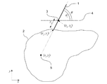
1)モデリング
図3に本実施形態でシミュレーションに用いるモデルの概要を示す。1は駆動可能な穿刺針であり不図示のマニピュレータに把持される。前述のとおり、マニピュレータは穿刺針1が体表4の刺入点3(xh,yh)を常に通過するように制御されることが望ましく、RCM機構が用いられてもよい。本実施形態では、穿刺針1のx軸に対する角度をθとおく。さらに、2は臓器を、5は穿刺目標部位(ターゲット)を表す。穿刺目標部位5と刺入点3(穿刺針1の回転中心)を結ぶ直線のx軸に対する角度をθtとおく。本実施形態では、穿刺針1の進入する距離をynと定義する。これより、針先端の座標(xe,ye)は、
![]()
![]()
臓器2は有限要素法を用いてモデル化される。本実施形態では、特許文献2の方法を用いている。特許文献2によれば、粘弾性を有する臓器の有限要素モデルは、Kを合成された剛性行列、Uを変位ベクトル、Dkをk次の分数微分オペレータ、Fを外力ベクトルとすると、
![]()

![]()
![]()
![]()
なお、臓器のモデルは、画像取得装置12などで取得した患者の臓器の画像から生成される。このとき、患者の年齢、性別、人種などの属性情報や、別の診断や測定で得られた情報を用いて、臓器の剛性行列を設定することも好ましい。このように患者自身の臓器モデルを利用することで、シミュレーションの信頼性を向上できる。
The model of the organ is generated from the image of the organ of the patient acquired by the
2)制御系設計
穿刺目標部位5に誤差なく到達するためには、穿刺目標部位5が穿刺針1の延長線上となるように角度θを設定し、穿刺を開始する。しかし、図4に示すように、針が進行するに従って臓器が変形し、穿刺目標部位が穿刺針の延長線上から逸脱してしまう。
2) Control System Design In order to reach the
本実施形態では、臓器モデルを用いてシミュレーションを行い、穿刺目標部位に誤差なく到達するために、穿刺針の進行に伴い、穿刺針の角度θを好適に動作させるためのプランニングを行う。そこで、シミュレーション上で穿刺誤差を最小にするようにロボットを制御する。ロボットの制御応答である時間ステップごとの角度θと針進行変位ynがプランニングの結果となる。 In this embodiment, simulation is performed using an organ model, and in order to reach the puncture target site without error, planning for suitably operating the angle θ of the puncture needle is performed as the puncture needle progresses. Therefore, the robot is controlled to minimize the puncturing error on the simulation. The angle θ for each time step, which is the control response of the robot, and the needle advancing displacement y n are the planning results.
穿刺誤差を最小にするには、穿刺針の角度θを常に、
![]()
差が生じてしまう。そこで、本実施形態では、その定常偏差を補償するために積分特性を含む補償器Krを用いて、穿刺針の角度θと穿刺目標部位のターゲット角度θtとの穿刺角度誤差θeを補償器Krの入力とするフィードバックループを設ける。穿刺角度誤差θeは下記式で表せる。
![]()
![]()
![]()
以上の構成により、穿刺針を進行させながら角度を制御し、高精度の穿刺プランニング結果を得るためのシミュレーションが可能である。本実施形態では穿刺精度をさらに向上させるために、針進行速度を穿刺反力Fnに応じて連続的に変化させる。それは、針が進行し組織切断が生じやすい状態で、式(3)に示したように臓器のひずみが大きくなり、弾性率が変化する。この弾性率の変化により、大きな穿刺角度誤差が生じてしまう。このとき針進行速度が一定であると、穿刺角度誤差を補償する十分な時間がないまま、組織切断が生じ、結果として大きな穿刺誤差が発生してしまう。そこで、針進行目標速度
![]()
![]()
本実施形態では図5に示すように穿刺反力Fnに応じてゲインKfを変化させる。穿刺反力が反力閾値Fnmin以下ではゲインKfを1とするため、穿刺針は一定速度で進行する。そして、穿刺反力が反力閾値Fnmin以上では、傾きakの一次関数で表される一定の低下率でゲインKfを減少させる。そして、ゲインKfの最低値としてKfminをあらかじめ決めておく。これよりゲインKfは、
図5の例では、反力閾値Fnminを6N、ゲインの最低値Kfminを0.2に設定したが、これらの値は臓器モデルごと(つまり患者ごと又は臓器の種類ごと)に変えてもよい。 In the example of FIG. 5, although the reaction force threshold F nmin is set to 6 N and the lowest value K fmin of gain is set to 0.2, even if these values are changed for each organ model (that is, for each patient or each type of organ) Good.
3)シミュレーション
前節で示した制御系を用いるシミュレーションの応答を示す。本実施形態では式(2)を増分形に変形し、非線形剛性についてはニュートン・ラプソン法を用い、粘弾性についてはサンプリング・スケーリング・プロパティーズを用いて演算する。
3) Simulation The response of the simulation using the control system shown in the previous section is shown. In this embodiment, the equation (2) is transformed into an incremental form, and the nonlinear stiffness is calculated using the Newton-Rapson method, and the viscoelasticity is calculated using the sampling scaling properties.
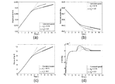
図6(a)に穿刺針の進行変位を、図6(b)に穿刺針の角度を、図6(c)に穿刺針先端が受ける反力を、図6(d)に穿刺角度誤差を示す。横軸は経過時間である。また、傾きakを−0.3に設定した場合の応答を実線で、傾きakを−0.16に設定した場合の応答を破線で、比較として進行速度を一定とする応答を点線で示す。さらに、本実施形態では穿刺反力が10N以上で針先端の組織の切断が発生する(又は切断発生の可能性が高まる)と仮定し、その時間帯を太線でプロットしている。以後、この反力の値(10N)を切断発生反力と呼ぶ。また、針進行速度の減速を開始する反力閾値Fnminを6Nとしている。反力閾値Fnminは穿刺針と臓器表面の接触の開始を判定するための閾値である。 6 (a), the angle of the puncture needle is shown in FIG. 6 (b), the reaction force received by the tip of the puncture needle in FIG. 6 (c), and the puncture angle error in FIG. 6 (d). Show. The horizontal axis is the elapsed time. In addition, the response when the slope a k is set to -0.3 is a solid line, the response when the slope a k is set to -0.16 is a broken line, and the response for making the traveling speed constant as a comparison is a dotted line Show. Furthermore, in the present embodiment, it is assumed that cutting of the tissue at the needle tip occurs (or the possibility of cutting increases) when the puncture reaction force is 10 N or more, and the time zone is plotted by a thick line. Hereinafter, the value (10 N) of this reaction force is referred to as a cutting reaction force. Further, a reaction force threshold F nmin for starting deceleration of the needle advancing speed is set to 6N. The reaction force threshold F nmin is a threshold for determining the start of the contact between the puncture needle and the organ surface.
図6(a)に示すように、本実施形態の穿刺制御(実線及び破線のライン参照)では穿刺反力が反力閾値Fnminを超えると(つまり、穿刺針が臓器に接触したと判定されると)減速を開始するので、進行変位の変化が緩やかになる。図6(b)に示すように、穿刺針の押圧により臓器が変形すると、穿刺目標部位は図2のy軸負の方向に移動する。そのため、本実施形態の制御系では穿刺角度を減少させ、穿刺針を反時計回り方向に制御することにより穿刺目標部位に追従している。図6(c)より、穿刺針の進行に応じて穿刺反力が上昇することがわかる。 As shown in FIG. 6A, in the puncture control of this embodiment (see the solid and broken lines), it is determined that the puncture needle is in contact with the organ when the puncture reaction force exceeds the reaction force threshold F nmin. Changes in the advancing displacement become gentler because deceleration is started. As shown in FIG. 6 (b), when the organ is deformed by the pressing of the puncture needle, the puncture target site moves in the y-axis negative direction of FIG. Therefore, in the control system of the present embodiment, the puncture angle is decreased, and the puncture needle is controlled in the counterclockwise direction to follow the puncture target site. From FIG. 6 (c), it can be seen that the puncture reaction force increases with the progress of the puncture needle.
図6(d)より、傾きakを−0.3に設定した場合の応答(実線)では、穿刺反力が10N以上である時間帯(太線でプロットした約7.2秒以後)で、十分に穿刺角度誤差が小さくなっていることがわかる。つまり、臓器の切断が発生する前に穿刺角度誤差を十分に補償できていることがわかる。比較として、従来の進行速度を一定とする制御(点線)では、4.5秒付近で、臓器の剛性が変化し、これにより穿刺誤差が発生する。そして、針進行速度が一定のため、その誤差を十分に補償する以前に穿刺反力が切断発生反力となる。これより、穿刺誤差が残ったまま針先端の組織切断が発生しやすいことがわかる。傾きakを−0.16に設定した場合の応答(破線)では、まず3.4秒付近で針進行の減速開始により穿刺角度誤差が発生する。そして、5.5秒付近で臓器の剛性が変化するため、さらに穿刺誤差が大きくなってしまう。その後は針の進行速度が低速となっているため、針の角度制御により、穿刺誤差を補償することができるが、結果として穿刺反力が切断発生反力を超える時間帯での穿刺角度誤差は、点線で示した針進行速度一定制御による応答よりも大きくなってしまう。 As shown in FIG. 6D, in the response (solid line) when the slope a k is set to -0.3, in a time zone in which the puncture reaction force is 10 N or more (after about 7.2 seconds plotted with thick line), It can be seen that the puncture angle error is sufficiently reduced. That is, it can be seen that the puncture angle error can be sufficiently compensated before the occurrence of the organ cutting. As a comparison, in the conventional control in which the advancing speed is constant (dotted line), the rigidity of the organ changes in the vicinity of 4.5 seconds, which causes a puncture error. Then, since the needle advancing speed is constant, the puncture reaction force becomes the cutting generation reaction force before the error is sufficiently compensated. From this, it is understood that tissue cutting of the tip of the needle is likely to occur with the puncturing error remaining. In the response (broken line) in the case where the slope a k is set to −0.16, a puncture angle error occurs due to the start of deceleration of the needle movement around 3.4 seconds. Then, since the rigidity of the organ changes in the vicinity of 5.5 seconds, the puncturing error further increases. After that, the needle advancing speed is low, so the needle angle control can compensate for the puncturing error, but as a result, the puncturing angle error in the time zone where the puncturing reaction force exceeds the cutting reaction force is This is larger than the response by the needle advancing speed constant control indicated by the dotted line.
再び傾きakを−0.3に設定した場合の応答(実線)に着目すると、3.4秒付近で針進行の減速開始により穿刺角度誤差が大きくなる。この誤差は減速度が大きいため、傾きakが−0.16である場合の応答よりも誤差が大きい。しかし、その後は進行速度が十分に低速となるため、臓器剛性の変化による穿刺角度誤差の増加はほとんど現れていないことがわかる。そして、穿刺角度誤差が十分に補償された状態で、穿刺反力が切断発生反力を超えることから、誤差の小さい高精度な穿刺が行われることがわかる。 Focusing on the response (solid line) in the case where the slope a k is set to -0.3 again, the puncture angle error becomes large due to the start of deceleration of the needle movement around 3.4 seconds. Since this error has a large deceleration, the error is larger than the response when the slope a k is −0.16. However, it can be seen that since the traveling speed is sufficiently low after that, there is almost no increase in the puncture angle error due to the change in organ stiffness. Then, in a state where the puncture angle error is sufficiently compensated, the puncture reaction force exceeds the cutting generation reaction force, and it is understood that a highly accurate puncture with a small error is performed.
以上示したように、針進行速度の減速条件を変えることで、針が臓器に接触してから切断が発生するまでの期間における穿刺角度誤差に違いがあることがわかる。また、図6(d)より、進行速度一定(従来の方法)や傾きakを−0.16とする条件に比べて、傾きakを−0.3とする条件の方が良好な結果が得られることがわかる。ただし、傾きakを−0.3とする条件が最適値というわけではない。傾きakを−0.3とする条件では、針進行が最低速となる時間が多くなり、全体の穿刺時間は長くなってしまうからである。特に6秒以降では穿刺誤差はすでに十分小さくなっていることから、最低速となる時間帯を短縮することで、穿刺時間を短縮できる余地がある。 As described above, it can be understood that there is a difference in the puncture angle error in the period from the contact of the needle with the organ to the occurrence of the cutting by changing the deceleration condition of the needle advancing speed. Further, from FIG. 6 (d), compared with the condition in which the traveling speed is constant (conventional method) and the gradient a k is -0.16, the condition in which the gradient a k is -0.3 is better It can be seen that However, the condition that the slope a k is −0.3 is not the optimum value. Under the condition that the inclination a k is −0.3, the time for the needle to travel at the lowest speed is increased, and the entire puncture time is increased. In particular, since the puncture error is already sufficiently small after 6 seconds, there is room for shortening the puncture time by shortening the lowest speed time zone.
そこで本実施形態では、傾きakの適切値を探索する。具体的には、−0.1から−0
.3まで0.01ステップで傾きakを変化しながら、前述の穿刺シミュレーションを複数回行い、その中から最良の結果が得られた傾きakを選択する。傾きakの良否を評価するための指標には、切断発生時に残存している穿刺誤差、穿刺に要する時間、針が接触を開始して以後の穿刺誤差の最大値をはじめとして様々な指標を用いることができ、また複数の評価指標を組み合わせもよい。
Therefore, in the present embodiment, an appropriate value of the slope a k is searched. Specifically, -0.1 to -0
. While changing a k gradient in 0.01 steps until 3, perform multiple puncture simulation described above, to select the slope a k that best results were obtained from. The index for evaluating the quality of the slope a k includes various indexes including the puncture error remaining at the time of cutting, the time required for the puncture, and the maximum value of the puncture error after the needle starts contact. It may be used, and a plurality of evaluation indexes may be combined.
本実施形態では、一例として、穿刺反力が切断発生反力となる時間帯での穿刺角度誤差の2ノルムと、針が接触を開始して以後の穿刺角度誤差の最大値、の2つの評価指標を用いる。図7(a)に傾きakの変化に対する穿刺角度誤差の2ノルムの変化を示し、図7(b)に傾きakの変化に対する穿刺角度誤差の最大値の変化を示す。なお、針と臓器の厳密な接触判定は必要ないので、図7(b)では、2秒以後の穿刺角度誤差の最大値をプロットした。 In this embodiment, as an example, two evaluations of the 2 norm of the puncture angle error in the time zone in which the puncture reaction force is the cutting reaction force, and the maximum value of the puncture angle error after the needle starts contact. Use the index. Figure 7 shows a 2-norm change in the puncture angle error with respect to a change in a k slope (a), the shows the change of the maximum value of the puncture angle error with respect to a change in a k slope in FIG. 7 (b). In addition, since exact contact determination of a needle | hook and an organ is unnecessary, in FIG.7 (b), the maximum value of the puncture angle error after 2 second was plotted.
図7(a)より、傾きakの絶対値が大きいほど、穿刺反力が反力閾値Fnminを超えた後速やかに低速な針進行になるため、穿刺反力が切断発生反力となる時間帯での誤差は小さくなる。しかし、傾きakの絶対値が大きいほど、速度変化が大きいため、例えば図6(d)では3から4秒に現れている速度変化時の穿刺誤差が大きくなってしまう。そこで本実施形態では、穿刺角度誤差の2ノルムと速度変化時の穿刺誤差の双方を考慮し、両方の値が許容範囲に収まるような傾きakを選択する。許容範囲に収まる傾きakの条件が複数ある場合には、その中で最も穿刺角度誤差の2ノルムが小さい条件を選べばよい。本実施形態では、ak=−0.24が適切値として選ばれる。 As shown in FIG. 7A, as the absolute value of the inclination a k is larger, the puncture reaction progresses rapidly after the puncture reaction force exceeds the reaction force threshold F nmin , so the puncture reaction force becomes a cutting generation reaction force. The error in the time zone becomes smaller. However, as the absolute value of the inclination a k is larger, the speed change is larger, and for example, the puncture error at the time of the speed change appearing in 3 to 4 seconds in FIG. Therefore, in the present embodiment, in consideration of both the 2 norm of the puncture angle error and the puncture error at the time of speed change, the slope a k is selected such that both values fall within the allowable range. In the case where there are a plurality of conditions of the inclination a k falling within the allowable range, it is sufficient to select the condition in which the 2-norm of the puncture angle error is smallest. In the present embodiment, a k = −0.24 is selected as an appropriate value.
図8に、本実施形態の提案手法で傾きakを適切値に設定した場合の穿刺誤差を実線で示す。また、比較例として、従来の一定速度の穿刺による誤差を点線で示し、穿刺反力が切断発生反力に達した時点で針進行速度を低速に切り替える制御を行った場合の穿刺誤差を破線で示す。図6(d)と同様に、穿刺反力が切断発生反力となる時間帯を太線でプロットしている。提案手法(実線)では穿刺反力が切断発生反力となる時間帯において穿刺誤差を最小化し、さらに穿刺時間も傾きakを適切値とすることで短縮化していることがわかる。これに対し、穿刺反力が切断発生反力に達した時点で速度を切り替える制御(破線)では、速度を切り替えた直後に臓器剛性の非線形性により大きな穿刺誤差が発生してしまうことがわかる。 FIG. 8 shows, in solid lines, a puncturing error when the slope a k is set to an appropriate value by the proposed method of the present embodiment. Also, as a comparative example, the error due to the conventional constant speed puncture is shown by a dotted line, and the puncture error when performing control to switch the needle advancing speed to a low speed when the puncture reaction force reaches the cutting generation reaction force is a dashed line. Show. Similar to FIG. 6 (d), the time zone in which the puncture reaction force becomes the cutting reaction force is plotted by a thick line. In the proposed method (solid line), it can be seen that the puncturing error is minimized in the time zone where the puncturing reaction force is the cutting reaction force, and the puncturing time is also shortened by setting the slope ak to an appropriate value. On the other hand, in the control (dotted line) in which the speed is switched when the puncture reaction force reaches the cutting generation reaction force, it can be seen that a large puncture error occurs due to the non-linearity of the organ stiffness immediately after switching the speed.
以上述べたように、本実施形態では、臓器の変形による目標部位の移動に追従するように針角度と針進行速度を制御するシミュレーションを、針進行速度の条件を変えながら複数回行い、その中から針進行速度条件の適切値を決定する。そして、そのシミュレーション結果に基づき穿刺のプランニングを行うため、穿刺誤差の小さい高精度な穿刺動作を実現することが可能となる。また本実施形態では、粘弾性及び非線形性を考慮した臓器モデルを用いて臓器の変形をシミュレートするので、より精度の高いプランニングが可能となる。 As described above, in the present embodiment, a simulation for controlling the needle angle and the needle advancing speed so as to follow the movement of the target part due to the deformation of the organ is performed multiple times while changing the conditions of the needle advancing speed. Determine an appropriate value for needle travel speed conditions from. Then, since puncturing planning is performed based on the simulation result, it is possible to realize a highly accurate puncturing operation with a small puncturing error. Further, in the present embodiment, since deformation of the organ is simulated using the organ model in which the viscoelasticity and the non-linearity are taken into consideration, more accurate planning is possible.
特に本実施形態では、穿刺反力に応じて針進行速度を低下させる速度調整を行うので、穿刺針の押圧で臓器が変形し目標部位が移動した場合でも、針角度を目標部位に追従させるための時間を確保でき、穿刺誤差を是正することが可能となる。そして、穿刺針が臓器表面を切断し臓器内に進入するより前に、穿刺誤差を十分に小さくすることができる。切断が発生した後は穿刺誤差は大きく変化しないと考えられるため、切断発生前に穿刺誤差の是正を完了しておくことで、針先端を目標部位に正確に到達させることが容易になる。しかも、針が臓器内に進入した後の軌道修正を最小限にできるため、臓器内の正常な組織を傷つけるリスクを低減することができる。 In particular, in the present embodiment, speed adjustment is performed to reduce the needle advancing speed according to the puncturing reaction force, so that the needle angle follows the target site even when the target site is moved due to deformation of the organ by pressing the puncture needle. Time can be secured, and the puncture error can be corrected. Then, the puncture error can be sufficiently reduced before the puncture needle cuts the surface of the organ and enters the organ. Since it is considered that the puncturing error does not change significantly after the occurrence of the cutting, by completing the correction of the puncturing error before the occurrence of the cutting, it becomes easy to make the needle tip accurately reach the target site. Moreover, since the trajectory correction after the needle enters the organ can be minimized, the risk of damaging the normal tissue in the organ can be reduced.
なお、上述した実施形態の構成は、本発明の一具体例を例示したものにすぎず、本発明
の範囲をそれらの構成にのみ限定する趣旨のものではない。例えば、上記実施形態では、針進行速度の条件として傾きakを変化させたが、針進行速度の低下率を決めるパラメータであればどのようなパラメータを変化させてもよい。また、上記実施形態では、穿刺反力に対し一定の低下率で速度を低下させたが、穿刺反力に応じて低下率を変化させてもよい。すなわち、穿刺反力に応じて針進行速度が連続的に変化させることができればよい。
The configuration of the above-described embodiment is merely an example of one specific example of the present invention, and the scope of the present invention is not limited to the configuration. For example, in the above embodiment, the inclination a k is changed as the condition of the needle advancing speed, but any parameter may be changed as long as it is a parameter that determines the decreasing rate of the needle advancing speed. Moreover, in the said embodiment, although speed was reduced with the fixed fall rate with respect to puncture reaction force, you may change the fall ratio according to puncture reaction force. That is, it is sufficient if the needle advancing speed can be continuously changed according to the puncture reaction force.
<第2実施形態>
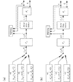
穿刺制御装置13の穿刺シミュレーション部130と穿刺プランニング部131の機能の別の実施形態として、図9(a)に穿刺シミュレーションで用いる穿刺ロボットの制御系のブロック線図を示す。ここで、Pliは第1実施形態と同様、臓器(本実施形態では肝臓)のモデルである。PCLは第1実施形態のサーボ系のモデルPCLfとPCLrの並列結合である。PCLは、針進行目標変位ynrefおよび針目標角度θrefを参照信号として、それに追従する内部フィードバックループを有する。PCLの制御出力が針進行変位ynおよび針角度θとなる。第1実施形態と同様に、Fn、θtはそれぞれ穿刺反力、ターゲット角度を示す。
Second Embodiment
As another embodiment of the functions of the
本実施形態では、針進行変位と針角度に対する3種類の参照信号ref1、ref2、ref3を有する制御系を用いてシミュレーションを行う。制御系は、時刻に応じて参照信号を切り替えるための切り替え部を有する。本実施形態では、穿刺針110が刺入点(穿刺針110の回転中心)とターゲット(目標部位)とを結ぶ直線と平行になる角度を初期ターゲット角度(第2の目標角度)θt0と定義する。参照信号ref1は、ターゲットに対する穿刺の前に、初期ターゲット角度θt0とは異なる角度θpで予備的な穿刺を行うための信号である。本実施形態では、この予備的な穿刺を予備穿刺又はシフト補償穿刺とよび、角度θpをシフト補償穿刺角度(第1の目標角度)とよぶ。シフト補償穿刺は、ターゲットをシフトさせるために行われる穿刺であり、臓器の切断が発生しないように(つまり針先端が臓器に到達しない程度の刺入量で)行うことが好ましい。ここで、臓器の切断が発生しない量の針進行変位をシフト補償穿刺変位ynpと定義する。参照信号ref2は、シフト補償穿刺からターゲットに対する穿刺へと遷移させるための参照信号であり、針進行変位を0へと戻すと同時に、針角度を初期ターゲット角度θt0へと回転させる。最後に、参照信号ref3は、針角度を初期ターゲット角度θt0に設定して、針を進行させるための信号である。本実施形態の手法では、参照信号ref1、ref2によるシフト補償穿刺により、参照信号ref3によるターゲットへの穿刺時に式(6)に示した穿刺誤差を最小化することができる。
In this embodiment, simulation is performed using a control system having three types of reference signals ref 1 , ref 2 , and ref 3 with respect to the needle advancing displacement and the needle angle. The control system has a switching unit for switching the reference signal according to the time. In this embodiment, an angle at which the
以上の構成により、臓器の変形によるターゲットの移動を補償するためのシフト補償穿刺動作のシミュレーションが可能である。穿刺シミュレーション部130は、シフト補償穿刺角度θpおよびシフト補償穿刺変位ynpを変更しながら穿刺シミュレーションを複数回行い、各条件でのシミュレーション結果をMemoryに蓄積する。シミュレーション結果は、例えば、時間ステップごとの針進行変位ynと針角度θの値を示す時系列データの形式で蓄積される。第1実施形態と同様に、穿刺プランニング部131は、条件の異なる複数のシミュレーション結果の中から最良のシミュレーション結果を選択し、そのシミュレーション結果に基づいて穿刺のプランニングを行う。
With the above configuration, it is possible to simulate a shift compensation puncturing operation for compensating for the movement of the target due to the deformation of the organ. The lancing
プランニング結果と実際の穿刺針110の状態とのずれを是正するようなガイド出力には、第1実施形態と同様に表示装置14や音声ガイドを用いることができる。さらに本実施形態の制御方法では、穿刺針を初期ターゲット角度θt0とシフト補償穿刺角度θpに物理的に固定できるようなV字型の器具を用いることも可能である。
As in the first embodiment, the
以下に、臓器及びロボットのモデリング、シミュレーションに用いる制御系について詳細に記述し、シミュレーションによって得られたプランニング結果を示す。 The following describes in detail the control system used for modeling and simulation of organs and robots, and shows the planning results obtained by simulation.
1)モデリング
モデルは第1実施形態と同様のモデルを用いる。
1) Modeling A model similar to that of the first embodiment is used.
2)制御系設計
本実施形態では、臓器モデルと制御系を用いてシミュレーションを行い、穿刺目標部位に誤差なく到達するための、シフト補償穿刺を伴うプランニングを行う。そこで、シミュレーション上で穿刺誤差を最小にするようにロボットを制御する。第1実施形態と同様に、ロボットの制御応答である時間ステップごとの角度θと針進行変位ynがプランニングの結果となる。図9(a)に穿刺シミュレーションで用いる穿刺ロボットの制御系のブロック線図を示す。
2) Control System Design In this embodiment, simulation is performed using an organ model and a control system, and planning with shift compensation puncturing is performed to reach the puncture target site without error. Therefore, the robot is controlled to minimize the puncturing error on the simulation. As in the first embodiment, the angle θ for each time step, which is the control response of the robot, and the needle advancing displacement y n become the planning result. FIG. 9A shows a block diagram of a control system of a lancing robot used in lancing simulation.
本実施形態の制御系では、ターゲットに対する穿刺(ターゲットへ向けて針を進入する穿刺)の前に、初期ターゲット角度(第2の目標角度)とは異なる第1の目標角度θpで穿刺を行う。この穿刺は予備的な穿刺であり、本実施形態ではこれをシフト補償穿刺とよび、その角度θpをシフト補償穿刺角度とよぶ。シフト補償穿刺では、臓器の切断が発生しないことが好ましく、その針進行変位をシフト補償穿刺変位ynpと定義する。参照信号ref1は、シフト補償穿刺ための参照信号である。参照信号ref2は、シフト補償穿刺からターゲットへの穿刺へと遷移させるための参照信号であり、針進行変位を0へと戻すと同時に、針角度を初期ターゲット角度θt0へと回転させる。そして、参照信号ref3は、針角度を初期ターゲット角度として、針をターゲットへと進行させるための参照信号である。シフト補償穿刺により、式(6)に示した穿刺誤差を最小化することが可能である。参照信号ref1からref2への切り替え、ref2からref3への切り替えは、切り替え部によって行われる。参照信号の切り替え時刻はシミュレーションのパラメータとして与える。
In the control system according to the present embodiment, puncture at a first target angle θ p different from the initial target angle (second target angle) is performed before puncturing on the target (puncture in which a needle is introduced toward the target). . This puncture is a preliminary puncture, and in this embodiment, it is referred to as a shift compensation puncture, and its angle θ p is referred to as a shift compensation puncture angle. In shift compensation puncturing, it is preferable that cutting of an organ does not occur, and its needle advancing displacement is defined as shift compensation puncturing displacement y np . The reference signal ref 1 is a reference signal for shift compensation puncturing. The reference signal ref 2 is a reference signal for transitioning from shift compensation puncturing to puncturing to the target, and simultaneously rotates the needle angle to the
シフト補償穿刺角度θpとシフト補償穿刺変位ynpを求める手順を図10のフローチャートに示す。まず、穿刺シミュレーション部130が、刺入点とターゲットの位置関係から初期ターゲット角度θt0を決定する(ステップS100)。つぎに、穿刺シミュレーション部130が、シフト補償穿刺変位ynpを微小値で固定し、シフト補償穿刺角度θpの角度範囲を、
θt0−θs<θp<θt0+θs (10)
と設定する(ステップS101)。式(10)において、θsは探索の範囲である。探索範囲θsが大きくなるほど、ターゲットのシフト補償変位を大きくすることができるが、穿刺針の側面により臓器を切断してしまう可能性が高まる。そこで、本実施形態ではθsを2/3πradとしている。そして、穿刺シミュレーション部130は、図9(a)に示す制御系を用いてシミュレーションを行い、穿刺誤差を算出する(ステップS102)。このとき、式(10)の範囲内でシフト補償穿刺角度θpを微小に変化させてシミュレーションを繰り返すことで、シフト補償穿刺角度θpごとの穿刺誤差を得る。穿刺シミュレーション部130は、穿刺誤差が最も小さくなる角度θpをシフト補償穿刺角度の最適値として採用する(ステップS103)。
A procedure for obtaining the shift compensation puncture angle θ p and the shift compensation puncture displacement y np is shown in the flowchart of FIG. First, the
θ t0 −θ s <θ p <θ t0 + θ s (10)
And (step S101). In equation (10), θ s is the search range. As the search range θ s increases, the shift compensation displacement of the target can be increased, but the possibility of cutting the organ by the side surface of the puncture needle increases. Therefore, in the present embodiment, θ s is 2 / 3π rad. Then, the
つぎに、穿刺シミュレーション部130は、決定したシフト補償穿刺角度θpを用いて、シフト補償穿刺変位ypの最適値を求める。具体的には、穿刺シミュレーション部130は、シフト補償穿刺角度θpを固定し、シフト補償穿刺変位ynpを0から微小ずつ増加させてシミュレーションを繰り返し、各変位ynpでの穿刺誤差を算出する(ステップS104)。シフト補償穿刺変位ynpは臓器の切断が発生しない範囲で変化させる。例えば、穿刺反力Fnの値を算出し、この値が所定値(例えば、10N)に達したらシミュレーションを終了すればよい。そして、穿刺シミュレーション部130は、穿刺誤差が最も小さくなる変位ynpをシフト補償穿刺変位の最適値として採用する(ステップS10
5)。以上の処理によって、穿刺誤差を最小とするシフト補償穿刺角度θpとシフト補償穿刺変位ynpを決定することができる。
Next, puncture the
5). By the above processing, it is possible to determine the shift compensation puncture angle θ p and the shift compensation puncture displacement y np that minimize the puncture error.
図9(a)では、針進行変位yと針角度θを制御することによりシフト補償穿刺を行ったが、針進行変位yの代わりに針穿刺力fを制御してもよい。針穿刺力fは穿刺針110の刺入方向に作用する力である。針穿刺力fと針角度θの制御系のブロック線図を図9(b)に示す。ここで、参照信号中のfnpはシフト補償穿刺力(第1の目標力)を示している。図9(b)の制御系を用いて、図10と同様の処理を行うことにより、シフト補償穿刺力fnpとシフト補償角度θpの最適値を求めることができる。
In FIG. 9A, shift compensation puncturing is performed by controlling the needle advancing displacement y and the needle angle θ, but instead of the needle advancing displacement y, the needle puncturing force f may be controlled. The needle puncture force f is a force acting in the insertion direction of the
3)シミュレーション
前節で示した制御系を用いるシミュレーションの応答を示す。まず、シフト補償穿刺変位ynpを微小値で固定し、シフト補償穿刺角度θpを微小に変化させてシミュレーションを繰り返すことで得られる応答を図11(a)に示す。横軸にシフト補償穿刺角度θpを示し、縦軸に穿刺誤差を示す。この穿刺誤差は、参照信号ref1によるシフト補償穿刺が終了した時点での穿刺誤差ではなく、参照信号ref2、ref3によるターゲットに対する穿刺までをシミュレーションした際の最終的な誤差を示している。また、本実施形態で設定したターゲットの初期ターゲット角度θt0は80.11degであり、式(10)に示した探索範囲であるθt0−θs、θt0+θsと共に、図中に破線で示している。本実施形態のターゲットは、シフト補償穿刺を行わずに、初期ターゲット角度を保って穿刺するとx負方向にシフトする。そのため、シフト補償穿刺はターゲットをx正方向にシフトさせる必要があり、そのためにはシフト補償穿刺角度θpを大きくとればよい。図11(a)のシミュレーション応答より、シフト補償穿刺角度θpを大きくするにつれて、穿刺誤差が減少してゆくことがわかる。本実施形態では有限要素モデルのメッシュ数の制約から最適なシフト補償穿刺角度θpを135.5degとするが、さらにメッシュを細分化して演算してもよい。
3) Simulation The response of the simulation using the control system shown in the previous section is shown. First, FIG. 11A shows a response obtained by fixing the shift compensation puncture displacement y np at a minute value and changing the shift compensation puncture angle θ p minutely to repeat the simulation. The abscissa represents the shift compensation puncture angle θ p , and the ordinate represents the puncture error. This puncture error is not a puncture error at the time when shift compensation puncture by the reference signal ref 1 is finished, but indicates a final error when simulating a puncture to a target by the reference signals ref 2 and ref 3 . Further, the initial target angle θ t0 of the target set in the present embodiment is 80.11 deg, and together with the search range θ t0 −θ s , θ t0 + θ s shown in the equation (10), a broken line in the drawing It shows. The target of the present embodiment shifts in the x negative direction when punctured while maintaining the initial target angle without performing the shift compensation puncture. Therefore, the shift compensation puncture needs to shift the target in the x positive direction, and in order to do so, the shift compensation puncture angle θ p should be increased. From the simulation response of FIG. 11A, it can be seen that the puncture error decreases as the shift compensation puncture angle θ p is increased. In the present embodiment, the optimum shift compensation puncture angle θ p is set to 135.5 deg because of the restriction on the mesh number of the finite element model, but the mesh may be further subdivided and calculated.
つぎに、得られたシフト補償穿刺角度θpを用いて、最適なシフト補償穿刺変位ynpを探索する。シフト補償穿刺変位ynpを0から増加させてシミュレーションを繰り返すことで得られる応答を図11(b)に示す。横軸にシフト補償穿刺変位ynpを示し、縦軸に穿刺誤差を示している。図11(b)より、シフト補償穿刺変位ynpを0.0273mとすることで、ターゲットに対する穿刺誤差が最小となることがわかる。 Next, an optimal shift compensation puncture displacement y np is searched using the obtained shift compensation puncture angle θ p . The response obtained by repeating the simulation with the shift compensation puncture displacement y np increased from 0 is shown in FIG. The horizontal axis indicates the shift compensation puncture displacement y np , and the vertical axis indicates the puncture error. From FIG. 11 (b), it can be seen that the puncturing error with respect to the target is minimized by setting the shift compensation puncturing displacement y np to 0.0273 m.
図12に本実施形態の制御系によるターゲット角度θtの時刻歴応答を実線で示す。シミュレーション開始時は、穿刺針はシフト補償穿刺角度θpに制御され、そして2秒まででシフト補償穿刺変位ynpに到達する。その後、2.8秒まで停止する。ここまでが参照信号ref1によって制御される。そして、2.8秒から4秒までの間で、参照信号ref2によって穿刺針の後進と、シフト補償穿刺角度θpから初期ターゲット角度θt0への回転が制御される。4秒から参照信号ref3による穿刺が行われ、制御系は穿刺反力Fnが切断発生反力(例えば10N)となるまで針を前進させる。切断発生の可能性が高まる時間帯である5.6〜6.1秒にかけて、穿刺誤差が十分に低減されていることがわかる。比較として、穿刺角度を初期ターゲット角度θt0に保ったまま穿刺を行った応答を破線で示す。針の前進につれてターゲットがシフトし、切断発生の可能性が高まる時間帯では穿刺誤差が残ってしまうことがわかる。 Figure 12 shows the time history of the target angle theta t by the control system of the present embodiment by a solid line. At the start of the simulation, the puncture needle is controlled to the shift compensation puncture angle θ p and reaches the shift compensation puncture displacement y np in up to 2 seconds. Then stop for 2.8 seconds. This is controlled by the reference signal ref 1 . Then, in the period from 2.8 seconds to 4 seconds, a reverse of the puncture needle to the reference signal ref 2, the rotation of the shift compensating puncture angle theta p to the initial target angle theta t0 is controlled. The puncturing is performed by the reference signal ref 3 from 4 seconds, and the control system advances the needle until the puncturing reaction force F n becomes a cutting reaction force (for example, 10 N). It can be seen that the puncturing error is sufficiently reduced in the period of 5.6 to 6.1 seconds, which is a time zone in which the possibility of occurrence of cutting increases. As a comparison, a response obtained by performing puncturing while keeping the puncturing angle at the initial target angle θt0 is indicated by a broken line. As the needle advances, the target shifts, and it is understood that a puncturing error remains in a time zone where the possibility of the occurrence of cutting increases.
図13(a)〜図13(l)にシミュレーション開始から0.5秒ごとの応答を示す。参照信号ref1、ref2、ref3による応答は、それぞれ図13(a)〜図13(e)、図13(f)〜図13(h)、図13(i)〜図13(l)に対応する。穿刺針の姿勢を実線で、初期ターゲット角度による軌道を破線で、ターゲットを点で示している。図13(a)〜図13(e)より、ターゲットはシフト補償穿刺によりx正方向にシフト
していることがわかる。図13(i)からは、穿刺針は初期ターゲット角度θt0による軌道上を前進する。図13(i)に示す穿刺針が刺入開始する状態では、ターゲットは軌道上からx正方向に外れているが、図13(j)、図13(k)に示すように、穿刺針が前進するにつれてターゲットは軌道上に戻ってゆく。そして、切断発生の可能性が高まる図13(l)の時間帯では、穿刺誤差が十分に低減されている。これより、本実施形態に示した穿刺針制御系が有効であることがわかる。また、シミュレーションで得られた結果を実際の穿刺のプランニング信号として用いることにより穿刺精度を向上させることができる。
13 (a) to 13 (l) show responses every 0.5 seconds from the start of simulation. The responses by the reference signals ref 1 , ref 2 and ref 3 are shown in FIGS. 13 (a) to 13 (e), 13 (f) to 13 (h) and 13 (i) to 13 (l), respectively. Corresponds to The posture of the puncture needle is indicated by a solid line, the trajectory according to the initial target angle is indicated by a broken line, and the target is indicated by a point. From FIGS. 13A to 13E, it can be seen that the target is shifted in the x positive direction by shift compensation puncturing. From FIG. 13 (i), the puncture needle advances on the trajectory at the initial target angle θt0 . In the state where the puncture needle shown in FIG. 13 (i) starts to insert, the target is out of the orbit in the x positive direction, but as shown in FIG. 13 (j) and FIG. 13 (k), the puncture needle is The target moves back into orbit as it moves forward. And in the time slot | zone of FIG. 13 (l) which the possibility of a cutting | disconnection occurrence increases, the puncture error is fully reduced. From this, it can be understood that the puncture needle control system shown in the present embodiment is effective. In addition, the puncture accuracy can be improved by using the result obtained by simulation as a planning signal of actual puncture.
1:穿刺針、2:臓器、5:穿刺目標部位
11:穿刺ロボット、12:画像取得装置、13:穿刺制御装置、21:臓器、22:目標部位、110:穿刺針、130:穿刺シミュレーション部、131:穿刺プランニング部
1: puncture needle, 2: organ, 5: puncture target site 11: puncture robot, 12: image acquisition device, 13: puncture controller, 21: organ, 22: target site, 110: puncture needle, 130: puncture simulation unit , 131: puncture planning unit
Claims (16)
前記シミュレーションの結果に基づいて、実際の臓器に対して穿刺を行う場合の穿刺針の動かし方をプランニングしてプランニング結果を出力するプランニング手段と、
を有し、
前記シミュレーション手段は、前記臓器の変形による前記目標部位の移動に追従するように前記穿刺針の向きを修正しながら前記穿刺針を進行させていく動作のシミュレーションを、前記穿刺針の進行速度の条件を変えながら、複数回行い、
前記プランニング手段は、前記穿刺針の進行速度の条件が異なる複数のシミュレーション結果のうち、穿刺誤差が所定の基準以下であるシミュレーション結果を選択し、前記選択されたシミュレーション結果を用いてプランニングを行い、
前記シミュレーション手段は、
前記シミュレーションにおいて、前記穿刺針が前記臓器から受ける力である穿刺反力に応じて前記穿刺針の進行速度を低下させる速度調整を行うとともに、前記条件として、前記速度調整における進行速度の低下率を決めるパラメータを変えながら、前記複数回のシミュレーションを行う
ことを特徴とする穿刺プランニング装置。 Simulation means for simulating the movement of the organ and the puncture needle when inserting the puncture needle toward a target site inside the organ by simulation using an organ model;
Planning means for planning how to move the puncture needle in the case of puncturing an actual organ based on the result of the simulation and outputting a planning result;
Have
The simulation means simulates an operation of advancing the puncture needle while correcting the direction of the puncture needle so as to follow the movement of the target site due to the deformation of the organ, the condition of the advancing speed of the puncture needle Done several times while changing the
The planning means selects a simulation result having a puncture error equal to or less than a predetermined reference among a plurality of simulation results under different conditions of the advancing speed of the puncture needle, and performs planning using the selected simulation result .
The simulation means is
In the simulation, while performing speed adjustment to decrease the advancing speed of the puncture needle according to the puncture reaction force which is a force that the puncture needle receives from the organ, the reduction rate of the advancing speed in the speed adjustment is set as the condition. A puncture planning apparatus characterized in that the simulation is performed a plurality of times while changing parameters to be determined.
ことを特徴とする請求項1に記載の穿刺プランニング装置。 The simulation means adjusts the advancing speed of the puncture needle by multiplying a predetermined initial value of the advancing speed by a speed gain determined according to the puncture reaction force. The puncture planning device according to 1.
前記シミュレーション手段は、前記条件として、下記式におけるパラメータakの値を変えながら、複数回のシミュレーションを行う
ことを特徴とする請求項2に記載の穿刺プランニング装置。
ここで、Kfは速度ゲイン、Fnは穿刺反力、Fnminは予め決めた閾値、akは速度ゲインの低下率を決めるパラメータ、Kfminは予め決めた速度ゲインの最低値である。 The velocity gain is determined by the following equation:
The puncture planning apparatus according to claim 2, wherein the simulation unit performs simulation a plurality of times while changing the value of the parameter a k in the following equation as the condition.
Here, K f is the velocity gain, F n puncture reaction force, F nmin is predetermined threshold, a k is a parameter that determines the reduction ratio of the velocity gain, K fmin is the minimum value of the predetermined velocity gain.
前記シミュレーションの結果に基づいて、実際の臓器に対して穿刺を行う場合の穿刺針の動かし方をプランニングしてプランニング結果を出力するプランニング手段と、を有し、
前記シミュレーション手段は、前記穿刺針の向きが第1の目標向きになるように前記穿刺針の向きを修正しながら前記穿刺針を第1の目標変位まで進行させた後、前記穿刺針の向きが第2の目標向きになるように前記穿刺針の向きを修正しながら前記穿刺針を前記目標部位に向けて進行させていく動作のシミュレーションを、前記第1の目標向きと前記第1の目標変位の条件を変えながら、複数回行い、
前記プランニング手段は、前記第1の目標向きと前記第1の目標変位の条件が異なる複数のシミュレーション結果のうち、穿刺誤差が所定の基準以下であるシミュレーション結果を選択し、前記選択されたシミュレーション結果を用いてプランニングを行う
ことを特徴とする穿刺プランニング装置。 Simulation means for simulating the movement of the organ and the puncture needle when inserting the puncture needle toward a target site inside the organ by simulation using an organ model;
Planning means for planning how to move the puncture needle in the case of puncturing an actual organ based on the result of the simulation and outputting a planning result;
The simulation means advances the puncture needle to a first target displacement while correcting the direction of the puncture needle such that the direction of the puncture needle becomes a first target direction, and then the direction of the puncture needle is A simulation of an operation of advancing the puncture needle toward the target site while correcting the direction of the puncture needle so as to be the second target direction, the first target direction and the first target displacement Multiple times, changing the conditions of
The planning means selects a simulation result having a puncture error equal to or less than a predetermined reference among a plurality of simulation results in which the first target direction and the condition of the first target displacement are different, and the selected simulation result puncturing planning apparatus and performs planning using.
前記シミュレーションの結果に基づいて、実際の臓器に対して穿刺を行う場合の穿刺針の動かし方をプランニングしてプランニング結果を出力するプランニング手段と、
を有し、
前記シミュレーション手段は、前記穿刺針の向きが第1の目標向きになるように前記穿刺針の向きを修正しながら前記穿刺針に作用する力が第1の目標力になるまで前記穿刺針を進行させた後、前記穿刺針の向きが第2の目標向きになるように前記穿刺針の向きを修正しながら前記穿刺針を前記目標部位に向けて進行させていく動作のシミュレーションを、前記第1の目標向きと前記第1の目標力の条件を変えながら、複数回行い、
前記プランニング手段は、前記第1の目標向きと前記第1の目標力の条件が異なる複数のシミュレーション結果のうち、穿刺誤差が所定の基準以下であるシミュレーション結果を選択し、前記選択されたシミュレーション結果を用いてプランニングを行う
ことを特徴とする穿刺プランニング装置。 Simulation means for simulating the movement of the organ and the puncture needle when inserting the puncture needle toward a target site inside the organ by simulation using an organ model;
Planning means for planning how to move the puncture needle in the case of puncturing an actual organ based on the result of the simulation and outputting a planning result;
Have
The simulation means advances the puncture needle until the force acting on the puncture needle becomes a first target force while correcting the direction of the puncture needle such that the direction of the puncture needle becomes a first target direction. The simulation of the operation of advancing the puncture needle toward the target site while correcting the direction of the puncture needle so that the direction of the puncture needle becomes the second target direction after Multiple times while changing the condition of the target direction of the target and the first target force,
The planning means selects a simulation result having a puncturing error equal to or less than a predetermined reference from among a plurality of simulation results in which the condition of the first target direction and the condition of the first target force are different, and the selected simulation result puncturing planning apparatus and performs planning using.
前記第1の目標向きは、前記第2の目標向きを含む所定の向き範囲から選ばれる向きであることを特徴とする請求項4又は5に記載の穿刺プランニング装置。 The second target direction is a direction in which the puncture needle is parallel to a straight line connecting the rotation center of the puncture needle and the target site,
The puncture planning device according to claim 4 or 5, wherein the first target orientation is an orientation selected from a predetermined orientation range including the second target orientation.
ことを特徴とする請求項1〜6のうちいずれか1項に記載の穿刺プランニング装置。 The planning means is a simulation in which the puncture error is equal to or less than a predetermined reference, the simulation result in which the error in the direction of the puncture needle with respect to the target site is minimized when the cutting of the organ by the puncture needle occurs. The puncture planning device according to any one of claims 1 to 6, which is selected as a result.
ことを特徴とする請求項1〜6のうちいずれか1項に記載の穿刺プランニング装置。 The planning means may include an error in the direction of the puncture needle with respect to the target site at the time when cutting of the organ by the puncture needle occurs, and the puncture needle may contact the organ and the subsequent target site with the target The simulation result in which both of the maximum value of the error in the direction of the puncture needle are in the allowable range is selected as the simulation result in which the puncture error is less than or equal to a predetermined reference. A puncture planning device according to item 1.
ことを特徴とする請求項1〜9のうちいずれか1項に記載の穿刺プランニング装置。 The said planning means outputs the information showing the direction of the said puncture needle for every time step, and advancing displacement, or advancing speed as said planning result, The said setting means is described in any one of the Claims 1-9 characterized by the above-mentioned. Puncture planning device.
前記穿刺プランニング装置で得られるプランニング結果に基づき、穿刺を行う者に対して穿刺針の動かし方をガイドするガイド手段と、
を有することを特徴とする穿刺システム。 The puncture planning device according to any one of claims 1 to 10,
Guide means for guiding how to move the puncture needle to the person performing the puncture based on the planning result obtained by the puncture planning device;
A lancing system characterized by having:
穿刺針を有するマニピュレータと、
前記穿刺プランニング装置で得られるプランニング結果に基づき、前記マニピュレータを制御する制御手段と、
を有することを特徴とする穿刺システム。 The puncture planning device according to any one of claims 1 to 10,
A manipulator having a puncture needle,
Control means for controlling the manipulator based on the planning result obtained by the puncture planning device;
A lancing system characterized by having:
コンピュータが、前記シミュレーションの結果に基づいて、実際の臓器に対して穿刺を行う場合の穿刺針の動かし方をプランニングしてプランニング結果を出力するプランニングステップと、
を有し、
前記シミュレーションステップでは、前記臓器の変形による前記目標部位の移動に追従するように前記穿刺針の向きを修正しながら前記穿刺針を進行させていく動作のシミュレーションを、前記穿刺針の進行速度の条件を変えながら、複数回行い、
前記プランニングステップでは、前記穿刺針の進行速度の条件が異なる複数のシミュレーション結果のうち、穿刺誤差が所定の基準以下であるシミュレーション結果を選択し、前記選択されたシミュレーション結果を用いてプランニングを行い、
前記シミュレーションステップでは、
前記シミュレーションにおいて、前記穿刺針が前記臓器から受ける力である穿刺反力に応じて前記穿刺針の進行速度を低下させる速度調整を行うとともに、前記条件として、前
記速度調整における進行速度の低下率を決めるパラメータを変えながら、前記複数回のシミュレーションを行う
ことを特徴とする穿刺プランニング方法。 A simulation step of simulating the movement of the organ and the puncture needle when the computer punctures the puncture needle toward a target site inside the organ by simulation using an organ model;
A planning step of planning how to move the puncture needle in the case of puncturing an actual organ based on the result of the simulation and outputting a planning result based on the result of the simulation;
Have
In the simulation step, a simulation of an operation of advancing the puncture needle while correcting the direction of the puncture needle so as to follow the movement of the target site due to the deformation of the organ, the condition of the advancing speed of the puncture needle Done several times while changing the
In the planning step, a simulation result having a puncture error equal to or less than a predetermined reference is selected from a plurality of simulation results under different conditions for the advancing speed of the puncture needle, and planning is performed using the selected simulation result .
In the simulation step,
In the simulation, while performing speed adjustment to decrease the advancing speed of the puncture needle according to the puncture reaction force which is a force that the puncture needle receives from the organ, the reduction rate of the advancing speed in the speed adjustment is set as the condition. A puncture planning method comprising performing the plurality of simulations while changing parameters to be determined.
コンピュータが、前記シミュレーションの結果に基づいて、実際の臓器に対して穿刺を行う場合の穿刺針の動かし方をプランニングしてプランニング結果を出力するプランニングステップと、
を有し、
前記シミュレーションステップでは、前記穿刺針の向きが第1の目標向きになるように前記穿刺針の向きを修正しながら前記穿刺針を第1の目標変位まで進行させた後、前記穿刺針の向きが第2の目標向きになるように前記穿刺針の向きを修正しながら前記穿刺針を前記目標部位に向けて進行させていく動作のシミュレーションを、前記第1の目標向きと前記第1の目標変位の条件を変えながら、複数回行い、
前記プランニングステップでは、前記第1の目標向きと前記第1の目標変位の条件が異なる複数のシミュレーション結果のうち、穿刺誤差が所定の基準以下であるシミュレーション結果を選択し、前記選択されたシミュレーション結果を用いてプランニングを行う
ことを特徴とする穿刺プランニング方法。 A simulation step of simulating the movement of the organ and the puncture needle when the computer punctures the puncture needle toward a target site inside the organ by simulation using an organ model;
A planning step of planning how to move the puncture needle in the case of puncturing an actual organ based on the result of the simulation and outputting a planning result based on the result of the simulation;
Have
In the simulation step, after the puncture needle is advanced to a first target displacement while correcting the direction of the puncture needle such that the direction of the puncture needle becomes a first target direction, the direction of the puncture needle is A simulation of an operation of advancing the puncture needle toward the target site while correcting the direction of the puncture needle so as to be the second target direction, the first target direction and the first target displacement Multiple times, changing the conditions of
In the planning step, among the plurality of simulation results in which the condition of the first target direction and the condition of the first target displacement are different, a simulation result having a puncture error equal to or less than a predetermined reference is selected and the selected simulation result puncture planning method and performing planning using.
コンピュータが、前記シミュレーションの結果に基づいて、実際の臓器に対して穿刺を行う場合の穿刺針の動かし方をプランニングしてプランニング結果を出力するプランニングステップと、
を有し、
前記シミュレーションステップでは、前記穿刺針の向きが第1の目標向きになるように前記穿刺針の向きを修正しながら前記穿刺針に作用する力が第1の目標力になるまで前記穿刺針を進行させた後、前記穿刺針の向きが第2の目標向きになるように前記穿刺針の向きを修正しながら前記穿刺針を前記目標部位に向けて進行させていく動作のシミュレーションを、前記第1の目標向きと前記第1の目標力の条件を変えながら、複数回行い、
前記プランニングステップでは、前記第1の目標向きと前記第1の目標力の条件が異なる複数のシミュレーション結果のうち、穿刺誤差が所定の基準以下であるシミュレーション結果を選択し、前記選択されたシミュレーション結果を用いてプランニングを行う
ことを特徴とする穿刺プランニング方法。 A simulation step of simulating the movement of the organ and the puncture needle when the computer punctures the puncture needle toward a target site inside the organ by simulation using an organ model;
A planning step of planning how to move the puncture needle in the case of puncturing an actual organ based on the result of the simulation and outputting a planning result based on the result of the simulation;
Have
In the simulation step, while the direction of the puncture needle is corrected such that the direction of the puncture needle becomes a first target direction, the puncture needle is advanced until a force acting on the puncture needle becomes a first target force. The simulation of the operation of advancing the puncture needle toward the target site while correcting the direction of the puncture needle so that the direction of the puncture needle becomes the second target direction after Multiple times while changing the condition of the target direction of the target and the first target force,
In the planning step, among the plurality of simulation results in which the condition of the first target direction and the condition of the first target force is different, a simulation result having a puncture error equal to or less than a predetermined reference is selected and the selected simulation result puncture planning method and performing planning using.
Priority Applications (3)
| Application Number | Priority Date | Filing Date | Title |
|---|---|---|---|
| JP2015083663A JP6521707B2 (en) | 2014-07-10 | 2015-04-15 | Puncture planning device and puncture system |
| US14/791,602 US10255247B2 (en) | 2014-07-10 | 2015-07-06 | Puncture planning apparatus and puncture system |
| US16/281,171 US11531726B2 (en) | 2014-07-10 | 2019-02-21 | Puncture planning apparatus and puncture system |
Applications Claiming Priority (3)
| Application Number | Priority Date | Filing Date | Title |
|---|---|---|---|
| JP2014142425 | 2014-07-10 | ||
| JP2014142425 | 2014-07-10 | ||
| JP2015083663A JP6521707B2 (en) | 2014-07-10 | 2015-04-15 | Puncture planning device and puncture system |
Publications (3)
| Publication Number | Publication Date |
|---|---|
| JP2016027844A JP2016027844A (en) | 2016-02-25 |
| JP2016027844A5 JP2016027844A5 (en) | 2018-02-08 |
| JP6521707B2 true JP6521707B2 (en) | 2019-05-29 |
Family
ID=55066128
Family Applications (1)
| Application Number | Title | Priority Date | Filing Date |
|---|---|---|---|
| JP2015083663A Active JP6521707B2 (en) | 2014-07-10 | 2015-04-15 | Puncture planning device and puncture system |
Country Status (2)
| Country | Link |
|---|---|
| US (2) | US10255247B2 (en) |
| JP (1) | JP6521707B2 (en) |
Families Citing this family (21)
| Publication number | Priority date | Publication date | Assignee | Title |
|---|---|---|---|---|
| JP6521707B2 (en) * | 2014-07-10 | 2019-05-29 | キヤノン株式会社 | Puncture planning device and puncture system |
| JP6520478B2 (en) * | 2015-06-30 | 2019-05-29 | 株式会社デンソーウェーブ | Robot arm operation system |
| US9532845B1 (en) * | 2015-08-11 | 2017-01-03 | ITKR Software LLC | Methods for facilitating individualized kinematically aligned total knee replacements and devices thereof |
| WO2018071573A1 (en) * | 2016-10-12 | 2018-04-19 | Intuitive Surgical Operations, Inc. | Surgical puncture device insertion systems and related methods |
| CN106725766A (en) * | 2017-01-05 | 2017-05-31 | 青岛市第三人民医院 | Ultrasound intervention sting device and piercing assembly |
| JPWO2018207498A1 (en) * | 2017-05-09 | 2020-05-14 | 国立大学法人 岡山大学 | Puncture robot and puncture control program |
| JP2018192246A (en) * | 2017-05-16 | 2018-12-06 | キヤノンメディカルシステムズ株式会社 | Ultrasonic diagnostic apparatus and ultrasonic diagnostic method |
| WO2019182917A1 (en) * | 2018-03-17 | 2019-09-26 | Canon U.S.A., Inc. | Method for virtual device positioning on skin surface in 3d medical image data |
| CN108665528A (en) * | 2018-04-12 | 2018-10-16 | 四川旭普信息产业发展有限公司 | Aeroplane photography digital modeling multi-subarea extracting and transfer algorithm |
| CN108784839A (en) * | 2018-06-20 | 2018-11-13 | 王�忠 | A kind of auxiliary robot device of peripheral blockade and intraspinal tube nerve block |
| CN109044498B (en) * | 2018-06-20 | 2021-03-05 | 复旦大学附属中山医院 | Arterial puncture system and method for determining arterial puncture position |
| CN111012514A (en) * | 2019-12-28 | 2020-04-17 | 天机医用机器人技术(清远)有限公司 | Puncture arm with direction function |
| CN112370162B (en) * | 2020-10-20 | 2022-06-03 | 哈尔滨医科大学 | Method for establishing image model puncture ablation path through multiple constraints |
| CN113509270B (en) * | 2021-07-09 | 2022-05-24 | 武汉联影智融医疗科技有限公司 | End tool motion guiding method and system and surgical robot |
| CN114376685B (en) * | 2021-07-20 | 2023-08-22 | 牡丹江医学院 | Intraspinal puncture ultrasonic probe |
| CN114224448B (en) * | 2021-12-21 | 2023-11-10 | 武汉大学 | Puncture path planning device, puncture path planning apparatus, and puncture path planning program |
| CN114305663B (en) * | 2022-01-19 | 2023-09-26 | 深圳臣诺医疗器械有限公司 | Method, device, equipment and medium for accurately determining incision of scalpel |
| CN114515195B (en) * | 2022-03-18 | 2023-09-15 | 华中科技大学同济医学院附属协和医院 | Lung puncture surgical robot |
| CN114965118B (en) * | 2022-04-13 | 2023-08-22 | 深圳市药品检验研究院(深圳市医疗器械检测中心) | Subcutaneous implantation type drug administration testing device |
| CN116052864B (en) * | 2023-02-03 | 2023-10-20 | 广东工业大学 | Digital twinning-based puncture operation robot virtual test environment construction method |
| CN116077155B (en) * | 2023-04-06 | 2023-06-27 | 深圳惟德精准医疗科技有限公司 | Surgical navigation method based on optical tracking equipment and mechanical arm and related device |
Family Cites Families (27)
| Publication number | Priority date | Publication date | Assignee | Title |
|---|---|---|---|---|
| US3032320A (en) | 1960-04-07 | 1962-05-01 | Simplex Wire & Cable Co | Buoyant cable bight puller |
| JPH06126679A (en) * | 1991-01-11 | 1994-05-10 | Yaskawa Electric Corp | Sewing operation robot |
| JPH10334275A (en) * | 1997-05-29 | 1998-12-18 | Canon Inc | Method and system for virtual reality and storage medium |
| DE10009166A1 (en) * | 2000-02-26 | 2001-08-30 | Philips Corp Intellectual Pty | Procedure for the localization of objects in interventional radiology |
| EP1501411B1 (en) * | 2002-04-22 | 2014-03-12 | Johns Hopkins University | Apparatus for insertion of a medical device during a medical imaging process |
| JP4528136B2 (en) * | 2005-01-11 | 2010-08-18 | 株式会社日立製作所 | Surgical device |
| US20100312129A1 (en) * | 2005-01-26 | 2010-12-09 | Schecter Stuart O | Cardiovascular haptic handle system |
| JP4390146B2 (en) * | 2005-03-28 | 2009-12-24 | 学校法人早稲田大学 | Puncture control device, puncture robot, and puncture control program |
| US7822458B2 (en) * | 2005-05-19 | 2010-10-26 | The Johns Hopkins University | Distal bevel-tip needle control device and algorithm |
| WO2007042986A2 (en) * | 2005-10-11 | 2007-04-19 | Koninklijke Philips Electronics, N.V. | 3d tool path planning, simulation and control system |
| WO2007077896A1 (en) * | 2005-12-27 | 2007-07-12 | Olympus Medical Systems Corp. | Encapsulated medical device guiding system and its control method |
| JP4757021B2 (en) * | 2005-12-28 | 2011-08-24 | オリンパス株式会社 | Position detection system |
| WO2007106558A2 (en) * | 2006-03-14 | 2007-09-20 | The Johns Hopkins University | Apparatus for insertion of a medical device within a body during a medical imaging process and devices and methods related thereto |
| CN101522134B (en) * | 2006-06-05 | 2012-06-27 | 泰克尼恩研究和发展基金有限公司 | Controlled steering of a flexible needle |
| EP2196131A4 (en) * | 2007-09-26 | 2012-12-05 | Olympus Medical Systems Corp | Introduction-into-subject system |
| JP5105330B2 (en) * | 2008-03-24 | 2012-12-26 | 学校法人早稲田大学 | Puncture planning support apparatus and program thereof, and insertion condition determination method |
| US9396669B2 (en) * | 2008-06-16 | 2016-07-19 | Microsoft Technology Licensing, Llc | Surgical procedure capture, modelling, and editing interactive playback |
| US8632468B2 (en) * | 2009-02-25 | 2014-01-21 | Koninklijke Philips N.V. | Method, system and devices for transjugular intrahepatic portosystemic shunt (TIPS) procedures |
| JP5761900B2 (en) * | 2009-06-08 | 2015-08-12 | 三菱プレシジョン株式会社 | Method for generating surgical simulation model, surgical simulation method, and surgical simulator |
| US20120219937A1 (en) * | 2009-11-02 | 2012-08-30 | Bangor University | Haptic needle as part of medical training simulator |
| JP5392770B2 (en) * | 2009-12-16 | 2014-01-22 | 独立行政法人産業技術総合研究所 | Needle-like surgical instrument insertion support device |
| FR2959409B1 (en) * | 2010-05-03 | 2012-06-29 | Gen Electric | METHOD FOR DETERMINING A TOOL INSERTION PATH IN A DEFORMABLE TISSUE MATRIX AND ROBOTIC SYSTEM USING THE METHOD |
| JP6170432B2 (en) * | 2010-10-08 | 2017-07-26 | コーニンクレッカ フィリップス エヌ ヴェKoninklijke Philips N.V. | Endoscope-assisted placement of vascular perforators |
| JP6120497B2 (en) * | 2012-06-26 | 2017-04-26 | キヤノン株式会社 | Puncture control device and method |
| JP6521707B2 (en) * | 2014-07-10 | 2019-05-29 | キヤノン株式会社 | Puncture planning device and puncture system |
| US10369045B2 (en) * | 2014-07-29 | 2019-08-06 | The Johns Hopkins University | Micromanipulation systems and methods |
| WO2016191361A1 (en) * | 2015-05-22 | 2016-12-01 | The University Of North Carolina At Chapel Hill | Methods, systems, and computer readable media for transoral lung access |
-
2015
- 2015-04-15 JP JP2015083663A patent/JP6521707B2/en active Active
- 2015-07-06 US US14/791,602 patent/US10255247B2/en active Active
-
2019
- 2019-02-21 US US16/281,171 patent/US11531726B2/en active Active
Also Published As
| Publication number | Publication date |
|---|---|
| JP2016027844A (en) | 2016-02-25 |
| US20160008082A1 (en) | 2016-01-14 |
| US10255247B2 (en) | 2019-04-09 |
| US20190188234A1 (en) | 2019-06-20 |
| US11531726B2 (en) | 2022-12-20 |
Similar Documents
| Publication | Publication Date | Title |
|---|---|---|
| JP6521707B2 (en) | Puncture planning device and puncture system | |
| US11207500B2 (en) | System and method for underactuated control of insertion path for asymmetric tip needles | |
| JP6120497B2 (en) | Puncture control device and method | |
| US11596483B2 (en) | Motion execution of a robotic system | |
| US20210137620A1 (en) | Robotic catheter system | |
| JP5303558B2 (en) | Robot control catheter and calibration method thereof | |
| JP5103658B2 (en) | Controlled operation of flexible needle | |
| JP4390146B2 (en) | Puncture control device, puncture robot, and puncture control program | |
| US20160213884A1 (en) | Adaptive catheter control for planar user interface | |
| US20110066160A1 (en) | Systems and methods for inserting steerable arrays into anatomical structures | |
| EP3473202B1 (en) | Robotic system for minimally invasive surgery | |
| CN109069803A (en) | Conduit force control device | |
| Legrand et al. | Active handheld flexible fetoscope–design and control based on a modified generalized prandtl-ishlinski model | |
| JP5105330B2 (en) | Puncture planning support apparatus and program thereof, and insertion condition determination method | |
| CN116098707B (en) | Wireless electromagnetic wave guided teleoperation system | |
| Loschak et al. | Predictive filtering in motion compensation with steerable cardiac catheters | |
| JP6388686B2 (en) | Surgery support apparatus, control method thereof, program, and surgery support system | |
| Ott et al. | Simultaneous physiological motion cancellation and depth adaptation in flexible endoscopy | |
| Abdoun et al. | A tape spring steerable needle capable of sharp turns | |
| CN116830212A (en) | System and method for generating and evaluating medical procedures | |
| CN117064548A (en) | Puncture control method for sliding mode control | |
| D'ETTORRE | Automated grasping of suturing needle for robotic surgical assistance | |
| Ma et al. | Dynamic performance analysis of a robotic catheter manipulating system |
Legal Events
| Date | Code | Title | Description |
|---|---|---|---|
| A521 | Request for written amendment filed |
Free format text: JAPANESE INTERMEDIATE CODE: A523 Effective date: 20171219 |
|
| A621 | Written request for application examination |
Free format text: JAPANESE INTERMEDIATE CODE: A621 Effective date: 20171219 |
|
| A131 | Notification of reasons for refusal |
Free format text: JAPANESE INTERMEDIATE CODE: A131 Effective date: 20181002 |
|
| A977 | Report on retrieval |
Free format text: JAPANESE INTERMEDIATE CODE: A971007 Effective date: 20180928 |
|
| RD02 | Notification of acceptance of power of attorney |
Free format text: JAPANESE INTERMEDIATE CODE: A7422 Effective date: 20181116 |
|
| A521 | Request for written amendment filed |
Free format text: JAPANESE INTERMEDIATE CODE: A523 Effective date: 20181203 |
|
| A131 | Notification of reasons for refusal |
Free format text: JAPANESE INTERMEDIATE CODE: A131 Effective date: 20190108 |
|
| A521 | Request for written amendment filed |
Free format text: JAPANESE INTERMEDIATE CODE: A523 Effective date: 20190307 |
|
| TRDD | Decision of grant or rejection written | ||
| A01 | Written decision to grant a patent or to grant a registration (utility model) |
Free format text: JAPANESE INTERMEDIATE CODE: A01 Effective date: 20190326 |
|
| A61 | First payment of annual fees (during grant procedure) |
Free format text: JAPANESE INTERMEDIATE CODE: A61 Effective date: 20190423 |
|
| R151 | Written notification of patent or utility model registration |
Ref document number: 6521707 Country of ref document: JP Free format text: JAPANESE INTERMEDIATE CODE: R151 |