JP5303558B2 - Robot control catheter and calibration method thereof - Google Patents
Robot control catheter and calibration method thereof Download PDFInfo
- Publication number
- JP5303558B2 JP5303558B2 JP2010521993A JP2010521993A JP5303558B2 JP 5303558 B2 JP5303558 B2 JP 5303558B2 JP 2010521993 A JP2010521993 A JP 2010521993A JP 2010521993 A JP2010521993 A JP 2010521993A JP 5303558 B2 JP5303558 B2 JP 5303558B2
- Authority
- JP
- Japan
- Prior art keywords
- catheter
- data points
- position data
- axis
- vector
- Prior art date
- Legal status (The legal status is an assumption and is not a legal conclusion. Google has not performed a legal analysis and makes no representation as to the accuracy of the status listed.)
- Expired - Fee Related
Links
Images


Classifications
-
- A—HUMAN NECESSITIES
- A61—MEDICAL OR VETERINARY SCIENCE; HYGIENE
- A61M—DEVICES FOR INTRODUCING MEDIA INTO, OR ONTO, THE BODY; DEVICES FOR TRANSDUCING BODY MEDIA OR FOR TAKING MEDIA FROM THE BODY; DEVICES FOR PRODUCING OR ENDING SLEEP OR STUPOR
- A61M25/00—Catheters; Hollow probes
- A61M25/01—Introducing, guiding, advancing, emplacing or holding catheters
- A61M25/0105—Steering means as part of the catheter or advancing means; Markers for positioning
- A61M25/0133—Tip steering devices
-
- A—HUMAN NECESSITIES
- A61—MEDICAL OR VETERINARY SCIENCE; HYGIENE
- A61B—DIAGNOSIS; SURGERY; IDENTIFICATION
- A61B1/00—Instruments for performing medical examinations of the interior of cavities or tubes of the body by visual or photographical inspection, e.g. endoscopes; Illuminating arrangements therefor
- A61B1/005—Flexible endoscopes
- A61B1/0051—Flexible endoscopes with controlled bending of insertion part
- A61B1/0052—Constructional details of control elements, e.g. handles
-
- A—HUMAN NECESSITIES
- A61—MEDICAL OR VETERINARY SCIENCE; HYGIENE
- A61B—DIAGNOSIS; SURGERY; IDENTIFICATION
- A61B34/00—Computer-aided surgery; Manipulators or robots specially adapted for use in surgery
- A61B34/70—Manipulators specially adapted for use in surgery
-
- A—HUMAN NECESSITIES
- A61—MEDICAL OR VETERINARY SCIENCE; HYGIENE
- A61B—DIAGNOSIS; SURGERY; IDENTIFICATION
- A61B34/00—Computer-aided surgery; Manipulators or robots specially adapted for use in surgery
- A61B34/70—Manipulators specially adapted for use in surgery
- A61B34/71—Manipulators operated by drive cable mechanisms
-
- A—HUMAN NECESSITIES
- A61—MEDICAL OR VETERINARY SCIENCE; HYGIENE
- A61B—DIAGNOSIS; SURGERY; IDENTIFICATION
- A61B5/00—Measuring for diagnostic purposes; Identification of persons
- A61B5/24—Detecting, measuring or recording bioelectric or biomagnetic signals of the body or parts thereof
- A61B5/25—Bioelectric electrodes therefor
- A61B5/279—Bioelectric electrodes therefor specially adapted for particular uses
- A61B5/28—Bioelectric electrodes therefor specially adapted for particular uses for electrocardiography [ECG]
- A61B5/283—Invasive
-
- A—HUMAN NECESSITIES
- A61—MEDICAL OR VETERINARY SCIENCE; HYGIENE
- A61B—DIAGNOSIS; SURGERY; IDENTIFICATION
- A61B5/00—Measuring for diagnostic purposes; Identification of persons
- A61B5/72—Signal processing specially adapted for physiological signals or for diagnostic purposes
- A61B5/7235—Details of waveform analysis
- A61B5/7253—Details of waveform analysis characterised by using transforms
- A61B5/7257—Details of waveform analysis characterised by using transforms using Fourier transforms
-
- A—HUMAN NECESSITIES
- A61—MEDICAL OR VETERINARY SCIENCE; HYGIENE
- A61B—DIAGNOSIS; SURGERY; IDENTIFICATION
- A61B90/00—Instruments, implements or accessories specially adapted for surgery or diagnosis and not covered by any of the groups A61B1/00 - A61B50/00, e.g. for luxation treatment or for protecting wound edges
- A61B90/10—Instruments, implements or accessories specially adapted for surgery or diagnosis and not covered by any of the groups A61B1/00 - A61B50/00, e.g. for luxation treatment or for protecting wound edges for stereotaxic surgery, e.g. frame-based stereotaxis
-
- A—HUMAN NECESSITIES
- A61—MEDICAL OR VETERINARY SCIENCE; HYGIENE
- A61B—DIAGNOSIS; SURGERY; IDENTIFICATION
- A61B17/00—Surgical instruments, devices or methods, e.g. tourniquets
- A61B17/00234—Surgical instruments, devices or methods, e.g. tourniquets for minimally invasive surgery
- A61B2017/00292—Surgical instruments, devices or methods, e.g. tourniquets for minimally invasive surgery mounted on or guided by flexible, e.g. catheter-like, means
- A61B2017/003—Steerable
-
- A—HUMAN NECESSITIES
- A61—MEDICAL OR VETERINARY SCIENCE; HYGIENE
- A61B—DIAGNOSIS; SURGERY; IDENTIFICATION
- A61B17/00—Surgical instruments, devices or methods, e.g. tourniquets
- A61B2017/00681—Aspects not otherwise provided for
- A61B2017/00694—Aspects not otherwise provided for with means correcting for movement of or for synchronisation with the body
- A61B2017/00699—Aspects not otherwise provided for with means correcting for movement of or for synchronisation with the body correcting for movement caused by respiration, e.g. by triggering
-
- A—HUMAN NECESSITIES
- A61—MEDICAL OR VETERINARY SCIENCE; HYGIENE
- A61B—DIAGNOSIS; SURGERY; IDENTIFICATION
- A61B17/00—Surgical instruments, devices or methods, e.g. tourniquets
- A61B2017/00681—Aspects not otherwise provided for
- A61B2017/00694—Aspects not otherwise provided for with means correcting for movement of or for synchronisation with the body
- A61B2017/00703—Aspects not otherwise provided for with means correcting for movement of or for synchronisation with the body correcting for movement of heart, e.g. ECG-triggered
-
- A—HUMAN NECESSITIES
- A61—MEDICAL OR VETERINARY SCIENCE; HYGIENE
- A61B—DIAGNOSIS; SURGERY; IDENTIFICATION
- A61B17/00—Surgical instruments, devices or methods, e.g. tourniquets
- A61B2017/00681—Aspects not otherwise provided for
- A61B2017/00725—Calibration or performance testing
-
- A—HUMAN NECESSITIES
- A61—MEDICAL OR VETERINARY SCIENCE; HYGIENE
- A61B—DIAGNOSIS; SURGERY; IDENTIFICATION
- A61B17/00—Surgical instruments, devices or methods, e.g. tourniquets
- A61B17/22—Implements for squeezing-off ulcers or the like on the inside of inner organs of the body; Implements for scraping-out cavities of body organs, e.g. bones; Calculus removers; Calculus smashing apparatus; Apparatus for removing obstructions in blood vessels, not otherwise provided for
- A61B2017/22072—Implements for squeezing-off ulcers or the like on the inside of inner organs of the body; Implements for scraping-out cavities of body organs, e.g. bones; Calculus removers; Calculus smashing apparatus; Apparatus for removing obstructions in blood vessels, not otherwise provided for with an instrument channel, e.g. for replacing one instrument by the other
- A61B2017/22074—Implements for squeezing-off ulcers or the like on the inside of inner organs of the body; Implements for scraping-out cavities of body organs, e.g. bones; Calculus removers; Calculus smashing apparatus; Apparatus for removing obstructions in blood vessels, not otherwise provided for with an instrument channel, e.g. for replacing one instrument by the other the instrument being only slidable in a channel, e.g. advancing optical fibre through a channel
- A61B2017/22075—Implements for squeezing-off ulcers or the like on the inside of inner organs of the body; Implements for scraping-out cavities of body organs, e.g. bones; Calculus removers; Calculus smashing apparatus; Apparatus for removing obstructions in blood vessels, not otherwise provided for with an instrument channel, e.g. for replacing one instrument by the other the instrument being only slidable in a channel, e.g. advancing optical fibre through a channel with motorized advancing or retracting means
-
- A—HUMAN NECESSITIES
- A61—MEDICAL OR VETERINARY SCIENCE; HYGIENE
- A61B—DIAGNOSIS; SURGERY; IDENTIFICATION
- A61B17/00—Surgical instruments, devices or methods, e.g. tourniquets
- A61B17/34—Trocars; Puncturing needles
- A61B17/3403—Needle locating or guiding means
- A61B2017/3405—Needle locating or guiding means using mechanical guide means
- A61B2017/3409—Needle locating or guiding means using mechanical guide means including needle or instrument drives
-
- A—HUMAN NECESSITIES
- A61—MEDICAL OR VETERINARY SCIENCE; HYGIENE
- A61B—DIAGNOSIS; SURGERY; IDENTIFICATION
- A61B34/00—Computer-aided surgery; Manipulators or robots specially adapted for use in surgery
- A61B34/20—Surgical navigation systems; Devices for tracking or guiding surgical instruments, e.g. for frameless stereotaxis
- A61B2034/2046—Tracking techniques
- A61B2034/2051—Electromagnetic tracking systems
- A61B2034/2053—Tracking an applied voltage gradient
-
- A—HUMAN NECESSITIES
- A61—MEDICAL OR VETERINARY SCIENCE; HYGIENE
- A61B—DIAGNOSIS; SURGERY; IDENTIFICATION
- A61B34/00—Computer-aided surgery; Manipulators or robots specially adapted for use in surgery
- A61B34/30—Surgical robots
- A61B2034/301—Surgical robots for introducing or steering flexible instruments inserted into the body, e.g. catheters or endoscopes
-
- A—HUMAN NECESSITIES
- A61—MEDICAL OR VETERINARY SCIENCE; HYGIENE
- A61B—DIAGNOSIS; SURGERY; IDENTIFICATION
- A61B34/00—Computer-aided surgery; Manipulators or robots specially adapted for use in surgery
- A61B34/70—Manipulators specially adapted for use in surgery
- A61B34/74—Manipulators with manual electric input means
- A61B2034/742—Joysticks
-
- A—HUMAN NECESSITIES
- A61—MEDICAL OR VETERINARY SCIENCE; HYGIENE
- A61B—DIAGNOSIS; SURGERY; IDENTIFICATION
- A61B2560/00—Constructional details of operational features of apparatus; Accessories for medical measuring apparatus
- A61B2560/02—Operational features
- A61B2560/0223—Operational features of calibration, e.g. protocols for calibrating sensors
-
- A—HUMAN NECESSITIES
- A61—MEDICAL OR VETERINARY SCIENCE; HYGIENE
- A61B—DIAGNOSIS; SURGERY; IDENTIFICATION
- A61B34/00—Computer-aided surgery; Manipulators or robots specially adapted for use in surgery
- A61B34/20—Surgical navigation systems; Devices for tracking or guiding surgical instruments, e.g. for frameless stereotaxis
-
- A—HUMAN NECESSITIES
- A61—MEDICAL OR VETERINARY SCIENCE; HYGIENE
- A61B—DIAGNOSIS; SURGERY; IDENTIFICATION
- A61B34/00—Computer-aided surgery; Manipulators or robots specially adapted for use in surgery
- A61B34/30—Surgical robots
-
- A—HUMAN NECESSITIES
- A61—MEDICAL OR VETERINARY SCIENCE; HYGIENE
- A61M—DEVICES FOR INTRODUCING MEDIA INTO, OR ONTO, THE BODY; DEVICES FOR TRANSDUCING BODY MEDIA OR FOR TAKING MEDIA FROM THE BODY; DEVICES FOR PRODUCING OR ENDING SLEEP OR STUPOR
- A61M25/00—Catheters; Hollow probes
- A61M25/01—Introducing, guiding, advancing, emplacing or holding catheters
- A61M25/0105—Steering means as part of the catheter or advancing means; Markers for positioning
Landscapes
- Health & Medical Sciences (AREA)
- Life Sciences & Earth Sciences (AREA)
- Surgery (AREA)
- Engineering & Computer Science (AREA)
- Public Health (AREA)
- Veterinary Medicine (AREA)
- General Health & Medical Sciences (AREA)
- Animal Behavior & Ethology (AREA)
- Heart & Thoracic Surgery (AREA)
- Biomedical Technology (AREA)
- Medical Informatics (AREA)
- Molecular Biology (AREA)
- Physics & Mathematics (AREA)
- Pathology (AREA)
- Nuclear Medicine, Radiotherapy & Molecular Imaging (AREA)
- Biophysics (AREA)
- Robotics (AREA)
- Mathematical Physics (AREA)
- Psychiatry (AREA)
- Optics & Photonics (AREA)
- Radiology & Medical Imaging (AREA)
- Artificial Intelligence (AREA)
- Computer Vision & Pattern Recognition (AREA)
- Physiology (AREA)
- Signal Processing (AREA)
- Oral & Maxillofacial Surgery (AREA)
- Cardiology (AREA)
- Pulmonology (AREA)
- Anesthesiology (AREA)
- Hematology (AREA)
- Media Introduction/Drainage Providing Device (AREA)
- Feedback Control In General (AREA)
Abstract
Description
【技術分野】
【0001】
(関連出願の相互参照)
本出願は、米国特許出願第11/139,908号明細書の一部継続出願である、2007年8月22日に出願された係属中の米国特許出願第11/843,589号明細書に対する優先権を主張する。本出願はまた、2006年12月29日に出願された係属中の米国特許出願第11/647,300号明細書、2006年12月29日に出願された係属中の米国特許出願第11/647,298号明細書、2006年12月29日に出願された係属中の米国特許出願第11/647,272号明細書、2006年12月29日に出願された係属中の米国特許出願第11/647,296号明細書、2006年12月29日に出願された係属中の米国特許出願第11/647,297号明細書および2006年12月29日に出願された係属中の米国特許出願第11/647,304号明細書にも関連する。上述したものは、その内容全体を本明細書に記載したものとして参照により本明細書に援用される。
【0002】
(技術分野)
本発明は、位置フィードバックシステムを採用するロボット制御装置に関する。特に、本発明は、位置フィードバックに関してロボット制御装置の作動を較正するために伝達関数を取得する方法に関する。
【背景技術】
【0003】
カテーテルが用いられる医療処置は、ますます増加し続けている。ごくわずかな例を挙げると、カテーテルは、診断処置、治療処置およびアブレーション処置に用いられている。通常、医師は、カテーテルを患者の脈管構造を通して、患者の心臓内の部位等の意図された部位まで操作する。カテーテルは、通常、アブレーション、診断、心臓マッピング等に使用され得る1つまたは複数の電極あるいは他の診断または治療装置を搭載している。
【0004】
カテーテルを患者の脈管構造を通して意図された部位まで操作するのを容易にするために、カテーテルシャフトの部分、特にその遠位領域を操縦可能にする場合があることは既知である。たとえば、カテーテルは、標的部位に向かう途中に患者の脈管構造の曲がりくねった経路を通り抜けるために、医師が必要に応じてかつ要求通りにカテーテルの遠位端を並進させ、回転させかつ偏向させることができるように、製造される場合がある。
【0005】
例として、偏向性は、1本または複数本の操縦ワイヤ(「プルワイヤ」と呼ぶ場合がある)をカテーテルシャフトの長さに沿って取り付けることによって達成されることが多い。これらの操縦ワイヤは1つまたは複数のアクチュエータに結合され、医師はそれを利用してワイヤに対し選択的に張力をかけることができ、それによってカテーテルの遠位端を偏向させる。カテーテルを偏向軸上で作動させるために、プルワイヤを電動式電気機械制御システムに結合する場合もあることも知られている。同様に、カテーテルを前進させかつ後退させる(すなわち、並進させる)ために、カテーテルを電動キャリッジに結合する場合もある。
【0006】
位置フィードバックシステム(位置確認システム、ナビゲーションシステムまたはマッピングシステムと呼ぶ場合もあり、本明細書ではそれらのさまざまな用語を同義で用いる)を用いることにより、医師に対し、患者内におけるカテーテルの位置に関する情報を提供することができる。米国特許第5,697,377号明細書(‘377特許)および同第5,983,126号明細書(‘126特許)(ともに、その内容全体を本明細書に記載されたものとして参照により明示的に本明細書に援用される)は、患者の心臓におけるカテーテルの位置を確定するナビゲーションシステムを開示している。
【0007】
‘377特許および‘126特許のシステムでは、患者の身体上に配置される互いに直交するように配置されたパッチ電極の対に電流パルスを印加する。これらのパッチを用いて、患者内部に一組の直交するx測定軸、y測定軸およびz測定軸を画定する電界を形成する。それらの特許は、各軸に1つ、3つの異なる周波数で連続的に供給される振幅の小さい低電流パルスを教示している。これら電界内、たとえば患者の心臓内に配置される位置決め電極には、各軸を画定するパッチ電極の対の間のその位置に応じて電圧がかかる。位置決め電極における電圧は、基準電極の電圧と比較した時、位置決め電極の基準電極に対する位置を示す。したがって、3つの電圧を使用して3次元空間において位置決め電極、したがってカテーテルの位置を画定することができ、それを、一組の直交する測定軸に対する直交(x、y、z)座標として表すことができる。
【0008】
カテーテルを作動させるために用いられるモータ自体は極めて精密であるが、カテーテルを偏向させ、並進させまたは回転させるために採用される機械系は、特に作動力をかなりの距離にわたって伝達しなければならない場合、それほど精密ではない。特に、カテーテル先端の位置は、カテーテルの温度、その最新移動過程、およびそれが横断している、曲がりくねった経路とともに、プルワイヤまたは他の機械系要素および電気機械系要素に供給される変位に対する予期されかつ所望される依存性を含む、多くの変動要素によって決まる。この変動性の多くが、カテーテル本体および内部カテーテル構造の長さに沿った保持力(それらをまとめて「記憶(memory)」と呼ぶ場合がある)による。実際に、プルワイヤの所与の変位に対し、これらの要因により、先端位置の変動が1cmを上回る結果となる場合がある。先端位置に望まれる相対的な変化も、同じ理由で正確に予測可能ではない。
【0009】
さらに、上述したナビゲーションシステム等の現行の位置フィードバックシステムには、固有の誤差がある可能性がある。心臓内ナビゲーションシステムは、再現性に関しては堅牢であるが、それらが提供する寸法フィードバックは、状況による(contexual)、すなわち、特定の患者、心腔構造および他の要因に左右される傾向にある。これは、すべての部位が同じ相対的な状況でマッピングされマークされるマッピング応用では問題はないが、カテーテルの開ループでの特性評価では問題がある。たとえば、ナビゲーションシステムが、10mmの偏向が必要であることを示す場合、この移動は、実際には、カテーテルの特性により9mmのみであり、1mmの誤差がもたらされる。このナビゲーションシステム誤差は、上述した装置誤差に加わるものである。
【発明の概要】
【発明が解決しようとする課題】
【0010】
したがって、3次元空間におけるカテーテルの所望の動きを、モータに供給される制御ベクトルまたは動作コマンド(本明細書では「移動ベクトル」と呼ぶ)に関連付ける伝達関数を得ることが望ましい。一次較正方法は、予測される移動に対してカテーテルを作動させ、上述したナビゲーションシステムを利用して実際の移動を測定するというものであり得る。予測された移動の実際の移動に対する比から、スケール補正係数を導出することができる。しかしながら、この手法は、カテーテル自体のいくつかの不確実性を考慮することはできるが、患者の動き、心臓の動き、患者の呼吸および電子ノイズ等の外部誤差源を考慮していない。
【課題を解決するための手段】
【0011】
本明細書では、ロボット制御心臓カテーテルおよびそのカテーテルを較正する方法を開示する。較正方法は、カテーテルに供給される作動と、位置フィードバックシステムにおいて患者の動き、心臓の動き、患者の呼吸および電子ノイズ等の外部誤差源を考慮しながら得られる作動との関係を確立する。これにより、ロボット制御カテーテルの正確かつ精密な制御が容易になる。
【0012】
本発明の第1実施形態によれば、少なくとも1つの作動軸に対する移動が可能なロボット装置を較正する方法は、概して、第1振動周波数で第1振動ベクトルを与えることにより、第1作動軸においてロボット装置を振動させるステップと、第1作動軸においてロボット装置を振動させている間に、ロボット装置の位置を周期的に測定するステップであって、それにより時間の関数として測定される第1の複数の位置データ点を生成するステップと、フーリエ変換アルゴリズムを用いて第1の複数の位置データ点を処理するステップであって、それにより第1振動ベクトルを与えることに起因するロボット装置の変位を隔離するステップと、処理するステップの出力を、第1作動軸に対する較正ベクトルに分解するステップとを含む。ロボット装置の位置は、約0.5秒〜約10秒の間のサンプリング間隔で、第1サンプリングレートで測定され、第1サンプリングレートは、第1振動周波数の少なくとも約2倍の倍数であることが好ましく、約5倍〜約10倍の間であることが好ましい。ロボット装置の位置を、複数の測定軸に対して測定してもよく、それにより、測定軸の各々に対して第1の複数の位置データ点が生成され、それを後にフーリエ変換アルゴリズムを用いて独立して処理してもよい。そして、較正ベクトルは、測定軸の各々に対して少なくとも1つの値を含むことができる。複数の位置データ点をバッファまたは他のメモリに格納してもよい。プロセスを、ロボット装置を作動させることができる他の任意の作動軸に対して繰り返してもよく、それらの作動軸に対し、振動周波数、サンプリング間隔およびサンプリングレートのうちのいずれかまたはすべては、任意に等しくてもよい。作動軸は、並進軸、回転軸および偏向軸を含むことが好ましい。
【0013】
本発明の別の実施形態によれば、少なくとも1つの作動軸に対する移動が可能なロボット制御カテーテルを較正する方法は、概して、第1振動周波数で第1振動ベクトルを与えることにより、第1作動軸においてカテーテルを機械的に作動させるステップと、カテーテルの位置を周期的に測定するステップであって、それにより時間の関数として測定される第1の複数の位置データ点を生成するステップと、フーリエ変換アルゴリズムを用いて第1の複数の位置データ点を処理するステップであって、それにより患者の動き、心臓の動き、呼吸および電子ノイズのうちの少なくとも1つからカテーテルの機械的作動を識別するステップと、処理するステップの出力を、第1作動軸に対する較正ベクトルに分解するステップとを含む。カテーテルの位置は、約0.5秒〜約10秒の間のサンプリング間隔で、第1サンプリングレートで測定され、第1サンプリングレートは、第1振動周波数の少なくとも約2倍の倍数であることが好ましく、約5倍〜約10倍の間であることが好ましい。サンプリングレートは、好ましくは約60Hz〜約200Hzの間であり、より好ましくは約100Hzであって、第1振動周波数は、好ましくは約1Hz〜約10Hzの間であり、より好ましくは約3Hz〜約5Hzの間である。カテーテルの位置、たとえばカテーテルの先端の位置を、複数の測定軸に対して測定してもよく、それにより、測定軸の各々に対して第1の複数の位置データ点が生成され、それを後にフーリエ変換アルゴリズムを用いて独立して処理してもよい。そして、較正ベクトルは、測定軸の各々に対して少なくとも1つの値を含むことができる。複数の位置データ点をバッファまたは他のメモリに格納してもよい。プロセスを、カテーテルを作動させることができる他の任意の作動軸に対して繰り返してもよく、それらの作動軸に対し、振動周波数、サンプリング間隔およびサンプリングレートのうちのいずれかまたはすべては、任意に等しくてもよい。作動軸は、並進軸、回転軸および偏向軸を含むことが好ましい。
【0014】
本発明のさらに別の実施形態では、ロボット制御カテーテルを較正する方法は、概して、或る振動周波数で振動ベクトルを与えることにより、作動軸においてカテーテルを振動させるステップと、カテーテルの或る点の位置を周期的に測定するステップであって、それにより時間の関数として測定される複数の位置データ点を生成するステップと、複数の位置データ点に対し信号処理アルゴリズムを適用するステップであって、それにより振動ベクトルを与えることに起因するカテーテルの変位を隔離するステップと、信号処理アルゴリズムの出力を、作動軸に対する較正ベクトルに分解するステップとを含む。信号処理アルゴリズムはフーリエ変換アルゴリズムであってもよい。複数のデータ点は、振動周波数の好ましくは倍数でありかつ少なくとも約2倍であり、より好ましくは約5倍〜約20倍の間であるサンプリングレートで測定される。カテーテルの位置を、1つまたは複数の測定軸に対して測定してもよく、それにより、測定軸の各々に対して複数の位置データ点が生成される。それにより、較正ベクトルは、測定軸の1つまたは複数の各々に沿って、ゼロ成分を含む少なくとも1つの成分を含んでいてもよい。複数の位置データ点をバッファまたは他のメモリに格納してもよい。作動軸は、並進軸、偏向軸および回転軸からなる群から選択されることが好ましい。
【0015】
本発明のさらに別の実施形態によれば、少なくとも1つの作動軸に対する移動が可能なロボット制御カテーテルを較正する方法は、第1振動周波数で第1振動ベクトルを与えることにより、第1作動軸においてカテーテルを機械的に作動させるステップと、カテーテルの位置を周期的に測定することにより、時間の関数として測定される第1の複数の位置データ点を生成するステップと、フーリエ変換アルゴリズムを用いて第1の複数の位置データ点を処理することにより、ロボット制御カテーテルの位置を第1作動軸に対する移動ベクトルに関連付ける伝達関数を生成するステップとを含む。この方法はさらに別の作業軸について繰り返してもよい。
【0016】
本発明のさらなる実施形態では、ロボット制御医療機器は、概して、医療処置を行うように構成されたエンドエフェクタと、エンドエフェクタを移動させるアクチュエータと、エンドエフェクタに対し作動軸における振動ベクトルを与えるようにアクチュエータを起動することにより、エンドエフェクタを機械的に作動させるコントローラと、エンドエフェクタの位置を周期的に測定し、それにより時間の関数として測定される複数の位置データ点を生成する位置フィードバックシステムと、フーリエ変換アルゴリズムに従って複数の位置データ点を処理することにより、エンドエフェクタの位置を作動軸に対する移動ベクトルに関連付ける伝達関数を生成するプロセッサとを有する。エンドエフェクタは心臓カテーテルであってもよい。位置フィードバックシステムは、1つまたは複数の測定軸に対してエンドエフェクタの端部の位置を周期的に測定してもよく、それにより1つまたは複数の測定軸の各々に対して複数の位置データ点が生成され、それを後にフーリエ変換アルゴリズムを用いて独立して処理してもよい。伝達関数は、1つまたは複数の測定軸の各々に沿って方向づけられる、ゼロ成分を含む少なくとも1つの成分を有する較正ベクトルを含んでいてもよい。
【発明の効果】
【0017】
本発明の技術的利点は、ロボット制御装置を較正するための伝達関数を導出する際に、装置変動性誤差、位置フィードバックシステム誤差および外部要因誤差を考慮する、というものである。
【0018】
本発明の上述したおよび他の態様、特徴、詳細、有用性および利点は、以下の説明および特許請求の範囲を読むことにより、かつ添付図面を検討することにより明らかとなろう。
【図面の簡単な説明】
【0019】
【図1】ロボット手術システムの一実施形態の概略図である。
【図2】カテーテルが配置されているカテーテル保持装置の一実施形態の斜視図である。
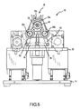
【図3】図2のカテーテル保持装置の端面図である。
【図4】カテーテルが固定されているカテーテル保持装置の一実施形態の斜視図である。
【図5】図4のカテーテル保持装置の端面図である。
【図6】ロボット手術システムで使用され得るような例示的な操縦可能カテーテルを示す。
【図7】本発明で使用され得るようなロボット手術システムおよび位置確認システムを概略的に示す。
【図8】ロボット制御心臓カテーテルまたは他のロボット制御装置を較正する方法のフローチャートである。
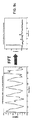
【図9a】x測定軸における例示的な較正グラフを、生データとして、およびフーリエ変換アルゴリズムの適用等による信号処理後として示す。
【図9b】y測定軸における例示的な較正グラフを、生データとして、およびフーリエ変換アルゴリズムの適用等による信号処理後として示す。
【図9c】z測定軸における例示的な較正グラフを、生データとして、およびフーリエ変換アルゴリズムの適用等による信号処理後として示す。
【発明を実施するための形態】
【0020】
図1は、医療機器12をロボット操作および制御するロボット手術システム10の一実施形態を概略的に示す。医療機器12はカテーテルであることが好ましく、それは、単に例としてかつ限定なしに、アブレーションカテーテル、ガイドワイヤカテーテル、イントロデューサカテーテル、プローブまたはスタイレットを含む、いかなるタイプのカテーテルであってもよい。しかしながら、本発明の範囲から逸脱することなく、ロボット手術システム10により、他のいかなる治療用医療機器、診断用医療機器または補助医療機器を制御してもよい、ということが理解されるべきである。こうした他の機器には、限定されないが、カテーテルが搬送または送達することができる、注射器、電気泳動装置、イオン導入装置、経皮薬剤送達装置、筋芽細胞送達装置、幹細胞送達装置、アブレーション装置、ステントおよびペースメーカリードがある。ロボット手術システム10を用いて、本明細書で説明する迅速な取付けおよび取外し機能に従って2つ以上の医療機器12を操作し制御してもよい、ということがさらに理解されるべきである。したがって、本明細書では、「医療機器」、「プローブ」、「治療用装置」および「カテーテル」という用語を同義で用いる。「エンドエフェクタ」という一般用語もまた、医療機器12を説明するために用いる場合もある。
【0021】
ロボット手術システム10は、概して、トラック14と、カテーテル保持装置16と、並進サーボ機構18と、カテーテル偏向制御機構20と、偏向サーボ機構22と、並進サーボ機構18および偏向サーボ機構22のうちの少なくとも一方に動作可能に結合されるコントローラ24とを有している。並進サーボ機構18および偏向サーボ機構22は、連続モータ、ステッピングモータ、液圧アクチュエータ、プーリシステム、および当業者には既知である他の装置を含む、或る距離を置いて機械制御を提供するいかなるタイプの装置であってもよい。カテーテル偏向制御機構20および偏向サーボ機構22を、本明細書ではまとめて「カテーテル偏向機構」と呼ぶ。
【0022】
カテーテル保持装置16は、カテーテル受入部26を有している。カテーテル受入部26は、カテーテル12の近位端30近くに位置するカテーテル制御ハンドル28をカテーテル受入部26内に取り付けることにより、カテーテル12を受け入れるように構成されている。カテーテル受け部26は、いかなるタイプのカテーテル12(または上述したように別の医療機器)の迅速な取付けおよび取外しにも適合されていることが好ましく、それにより、ロボット手術システム10による制御のための装置12の取付け、および手動制御(たとえば、カテーテル制御ハンドル28の使用者による操作)のための装置12の取外しが容易になる。したがって、カテーテル制御ハンドル28を、摩擦嵌合により、あるいは1つまたは複数のクイックリリースファスナを用いて、カテーテル受入部26に固定することができる。別法として、カテーテル受入部26の内面とカテーテル制御ハンドル28の外面は、カテーテル制御ハンドル28をカテーテル保持装置16内にねじ込むことができるようにする嵌合ねじ部を有していてもよい。ロボット手術システム10の他の実施形態では、カテーテル制御ハンドル28は、カテーテル受入部26の適所に締め付けられるかまたはひもで縛られる。カテーテル受入部26内にカテーテル制御ハンドル28を受け入れるのを容易にするために、アダプタを用いてもよい。
【0023】
図2および図3に、カテーテル制御ハンドル28が配置されているが固定されてはいない、カテーテル保持装置16の一実施形態を示す。カテーテル保持装置16は、基板32と複数の直立した支持板34とを有している。支持板34は、プーリシステム38に連結されたカム36を支持する。
【0024】
カテーテル制御ハンドル28は、開口部40内を下方に、カテーテル受入部26内のプーリシステム38のベルト40の上に受け入れられる。カテーテル制御ハンドルが下方に付勢されると、ベルト40が上部プーリ38aおよび下部プーリ38bを矢印aの方向に回転させる。これにより、カム36がリンク42を介して下方に付勢され、上部プーリ38a、38bがリンク44を介して互いに向かって引き寄せられ、同時にベルト40がカテーテル制御ハンドル28の周囲に巻き付けられる。それにより、カテーテル制御ハンドル28が、図4および図5に示すようにカテーテル受入部26内に固定される。カテーテル制御ハンドル28をカテーテル保持装置16から取り外すためには、使用者は、カム26を解放するだけでよく、それは、上述したプロセスを逆転し、カテーテル受入部26を開放する。
【0025】
カテーテル保持装置16は、トラック14に並進可能に関連している。「並進可能に関連する」という句は、カテーテル保持装置16とトラック14とのすべての種類の相対的な横方向の動きを含む。たとえば、カテーテル保持装置16は、トラック14に対して摺動してもよい。別法として、カテーテル保持装置16は、トラック14に取り付けられているウォームギア、親ねじ、ボールねじ等のねじ機構46に沿って横方向に移動してもよい。カテーテル保持装置16のトラック14に対する並進範囲(すなわち、カテーテル保持装置16が両端の間でトラック14に対して移動することができる横方向距離)は、少なくとも約5cmであり、人間の心臓のおよその幅であることが好ましい。トラック14に対するカテーテル保持装置16の並進範囲が少なくとも約10cmであることがより好ましい。
【0026】
本発明の好ましい実施形態では、キャリッジ48が、ねじ機構46を介してトラック14の上に並進可能に取り付けられている。カテーテル保持装置16は、キャリッジ48によりトラック14に対して並進するように、キャリッジ48に取り付けられている。たとえば、基板32を、キャリッジ48に固定してまたは取外し可能に取り付けてもよい。別法として、カテーテル保持装置16を、キャリッジ48と、単一アセンブリとして一体的に形成してもよい(すなわち、基板32およびキャリッジ48が単一の単体部品であってもよい)。同様に、本発明の実施形態によっては、カテーテル保持装置16を、キャリッジが介在することなくトラック14に直接並進可能に取り付けてもよい。
【0027】
並進サーボ機構18は、カテーテル保持装置16に動作可能に結合され、カテーテル保持装置16のトラック14に沿った横方向の位置を調整するために、カテーテル保持装置16のトラック14に対する並進を制御するように適合されている。並進サーボ機構18は、キャリッジ48、したがってそれに取り付けられているカテーテル保持装置16を、トラック14に沿って横方向に移動させるために、キャリッジ48に動作可能に結合されていることが好ましい。図1に示す実施形態では、並進サーボ機構18は、ねじ機構46を駆動し、それによりキャリッジ48をねじ機構46に沿って横方向に移動させる。
【0028】
偏向サーボ機構22は、カテーテル偏向制御機構20に動作可能に結合されかつそれを制御するように適合されている。本発明の好ましい実施形態では、偏向サーボ機構22は、カテーテル偏向制御機構20を回転させることができるように、カテーテル偏向制御機構20に動作可能に結合されている。偏向サーボ機構22とカテーテル偏向制御機構20とを連結する伝達系を簡略化するために、偏向サーボ機構22およびカテーテル偏向制御機構20のいずれか一方または両方をキャリッジ48に取り付けてもよい。ロボット手術システム10の実施形態によっては、後述するように、カテーテル偏向制御機構20はカテーテル保持装置16に、たとえばプーリシステム38、特にベルト40を利用することにより組み込まれる。しかしながら、当業者は、本発明の精神および範囲から逸脱することなく、カテーテル偏向制御機構20をカテーテル保持装置16から分離してもよい、ということを理解するであろう。
【0029】
コントローラ24は、カテーテル保持装置16に受け入れられるカテーテル12をナビゲートするために、並進サーボ機構18および偏向サーボ機構22の少なくとも一方を制御するように適合されている。並進サーボ機構18および偏向サーボ機構22を制御するために複数のコントローラを使用することが、本発明の範囲内にあるとみなされることも留意されるべきである。この開示を通して、「コントローラ」という用語は、1つまたは複数のロボットシステムの移動または作動を制御する装置(すなわち、サーボ機構にコマンド入力を提供する構成要素)を指す。当業者は、ロボット手術システム10内で任意の特定の機構に対して、適当なコントローラをいかに選択するかを理解するであろう。さらに、「コントローラ」という用語は、1つまたは複数のロボットシステムを作動させる単一の統合コントローラと複数のコントローラとの両方を包含するものとみなされるべきである。
【0030】
図6に示すように、カテーテル12は、カテーテル12の近位端30近くのカテーテル制御ハンドル28からカテーテル12の遠位端52まで延在する少なくとも1本のプルワイヤ50を含む、操縦可能カテーテルであることが好ましい。プルワイヤ50を、同様にカテーテル12の遠位端52近くに位置する少なくとも1つのプルリング54に結合してもよい。プルワイヤ50は、緊張状態になると、カテーテル12の遠位端52をさまざまな形状になるように偏向させる。当業者は理解するように、プルワイヤ50を追加することにより、カテーテル12の遠位端52の偏向の多様性が向上する。たとえば、プルリング54への取付点が1つである単一プルワイヤ50により、カテーテル12の遠位端52は、単一軸上で、恐らくは一方向のみに、たとえば図6に対して上方に偏向することができる。第2プルワイヤ50を追加する(図6に示すように)ことにより、または単一プルワイヤ50を輪にしてプルリング54に2つの取付点56があるようにすることにより、カテーテル12の遠位端52を、2つの方向に、たとえば図6に対して上方および下方の両方に偏向させてもよい。4つのプルワイヤ50がプルリング54に約90°の間隔で取り付けられるカテーテル12は、4つの方向に、たとえば図6に対し上方、下方および用紙面に入る方向および出る方向に偏向することができる。
【0031】
カテーテル制御ハンドル28に1つまたは複数のカテーテル偏向アクチュエータ58を設けることにより、1本または複数本のプルワイヤ50に選択的に張力をかけるようにしてもよく、それにより、カテーテル12の遠位端52の偏向の方向および程度が制御される。実施形態によっては、1つまたは複数のノブを設けてもよく、その回転により、1本または複数本のプルワイヤ50に選択的に張力がかけられる。しかしながら、カテーテル偏向アクチュエータ58は、本発明の精神および範囲から逸脱することなく、限定されないがスライダおよびスイッチを含む他の多くの形態をとってもよいということが理解されるべきである。さらに、カテーテル制御ハンドル28自体を回転させることにより、選択的にプルワイヤ50に張力をかけカテーテル12の遠位端52を偏向させてもよい、ということも企図される。
【0032】
図1に戻ると、カテーテル制御ハンドル28がカテーテル受入部26内に受け入れられると、カテーテル12は、カテーテル保持装置16によりトラック14に対して並進し、それにより、カテーテル12を患者の体内に前進させかつ患者の体内から後退させることを可能にする第1自由度が提供される。さらに、カテーテル12は、カテーテル偏向制御機構20に動作可能に結合されており、カテーテル偏向制御機構20の作動によってカテーテル12の遠位端52が偏向し、それにより、カテーテル12に対し第2自由度が提供される。特に、カテーテル偏向アクチュエータ58をカテーテル偏向制御機構20に動作可能に結合してもよく、それによりカテーテル偏向制御機構20は、カテーテル偏向アクチュエータ58を作動させて、選択的に1本または複数本のプルワイヤ50に張力をかけ、カテーテル12の遠位端52を所望の方向に所望の量だけ偏向させることができる。
【0033】
本発明の実施形態によっては、カテーテル偏向制御機構20を回転させることにより、カテーテル偏向アクチュエータ58が回転し、それによりカテーテル12内で1本または複数本のプルワイヤ50に選択的に張力がかけられる。カテーテル偏向制御機構20とカテーテル偏向アクチュエータ58との間の伝達系は、たとえばカテーテル偏向制御機構20およびカテーテル偏向アクチュエータ58を包囲するゴム引きコーティングによって提供される、摩擦嵌合であってもよい。別法として、カテーテル偏向制御機構20およびカテーテル偏向アクチュエータ58を、嵌合ギア歯またはローレット削りによって結合してもよい。
【0034】
特に、図2〜図5に示すカテーテル保持装置16の実施形態を参照すると、カテーテル12がカテーテル受入部26に固定されると、ベルト40がカテーテル制御ハンドル28と摩擦係合する。それらはまた、カテーテル偏向アクチュエータ58と係合してもよい。したがって、プーリシステム38が偏向サーボ機構22によって駆動された場合、ベルト40は、選択的に1本または複数本のプルワイヤ50に張力をかけカテーテル12の遠位端52を偏向させるために、カテーテル制御ハンドル28またはカテーテル偏向アクチュエータ58あるいは両方を回転させることができる。
【0035】
上述したカテーテル偏向制御機構20およびカテーテル偏向アクチュエータ58の特定の構成は、単に例示的なものであり、本発明の精神および範囲から逸脱することなく変更が可能である、ということが理解されるべきである。たとえば、カテーテル偏向アクチュエータ58がノブではなくスライダである場合、カテーテル偏向制御機構20を、スライダを作動させるように好適に変更してもよく、またはさらにはモジュラユニットとして置き換えてもよい。これにより、さまざまな構成の既製医療機器とロボット手術システム10との容易な取付けおよび相互接続を可能にすることによって、ロボット手術システム10の迅速接続/分離操作が容易になる。
【0036】
上述したように、カテーテル12内に追加のプルワイヤ50を含めることにより、カテーテル12の遠位端52が偏向することができる方向の数が増加する。これを、本明細書では「偏向多様性」と呼ぶ。しかしながら、使用されるプルワイヤ50の数が比較的少ない場合(たとえば、約4本未満のプルワイヤ50)、失われる偏向多様性を、カテーテル12をその軸を中心に回転させることによって補償してもよい。たとえば、プルリング54への取付点が1つである単一プルワイヤ50のみを使用し、一方向にしか偏向することができないカテーテルでは、カテーテルを、単にその軸を中心に180°回転させることにより、反対方向に偏向させることができる。同様に、180°離れた2つの方向に偏向することができるカテーテルを、その軸を中心に90°回転させることにより、それらの間の中間の方向に偏向させることができる。
【0037】
したがって、本発明の実施形態によれば、カテーテル受入部26は回転可能である。こうした回転可能カテーテル受入部の一例は、図2〜図5に示すプーリシステム38によって画定されるカテーテル受入部26である。回転可能なカテーテル受入部26には回転サーボ機構60が回転可能に結合されており、回転可能なカテーテル受入部26を制御するように適合されている。したがって、プーリシステム38は、回転サーボ機構60によって駆動されてもよく、それにより、ベルト40と係合してカテーテル12をその軸を中心に回転させる。
【0038】
望ましい場合、回転サーボ機構60を、カテーテル保持装置16とともにトラック14に対して並進するように、キャリッジ48に取り付けるかまたはカテーテル保持装置16に取り付けてもよい。この構成により、回転サーボ機構60とカテーテル保持装置16との間に一定の距離関係がもたらされ、それによって、回転サーボ機構60をカテーテル保持装置16に結合する伝達系を簡略化することができる。
【0039】
カテーテル12は、カテーテル保持装置16に取り付けられると、カテーテル受入部26とともに回転し、それにより、カテーテル12に対して第3自由度が提供され、プルワイヤ50の数が比較的少ないことに起因する低い偏向多様性が補償される。カテーテル受入部26は、その軸を中心に少なくとも約360°回転可能であることが好ましく、それにより、そこに受け入れられたカテーテル12もまた、その軸を中心に少なくとも360°回転可能であり、それにより、カテーテル12の遠位端52の実質的に任意の方向での偏向が容易になり、カテーテル12の遠位端52の偏向多様性が大幅に向上する。カテーテル受入部26を、その軸を中心に約720°以上回転するように設計してもよい。
【0040】
カテーテル受入部26を回転させることによってカテーテル12を回転させることにより、カテーテル12の遠位端52が意図せず偏向することがある。当業者がこの開示から理解するように、カテーテル受入部26およびカテーテル12が回転する際、回転サーボ機構60によって加えられるトルクがカテーテル偏向制御機構20の慣性に打ち勝つには不十分である場合、カテーテル偏向アクチュエータ58は、カテーテル制御ハンドル28と回転するのではなく、固定されたままであることがある。すなわち、カテーテル偏向アクチュエータ58は、カテーテル偏向制御機構20に抗して動かないことがあり、カテーテル制御ハンドル28とカテーテル偏向アクチュエータ58との間に相対的な回転がもたらされる。この相対的な回転により、1本または複数本のプルワイヤ50に指示されていない張力が加わり、カテーテル12の遠位端52が不注意に偏向することがある。
【0041】
したがって、カテーテル12が回転する際に実質的に一定の偏向を維持するために、コントローラ24を、回転サーボ機構60と偏向サーボ機構22との両方に動作可能に結合してもよい。コントローラ24は、偏向サーボ機構22および回転サーボ機構60のうちの少なくとも一方を制御して、好ましくは偏向サーボ機構22および回転サーボ機構60の両方を同時に制御して、カテーテル受入部26およびカテーテル12が回転する際に遠位端52の実質的に一定の偏向を維持するよう適合されている。たとえば、コントローラ24は、回転サーボ機構60に対しカテーテル受入部26を回転させるように命令する際、同時に、偏向サーボ機構22に対し、カテーテル偏向制御機構20を反対方向に回転するよう作動させるように命令してもよく、それにより、カテーテル偏向アクチュエータ58とカテーテル制御ハンドル28との間の相対的な回転が実質的になくなり、カテーテル12の実質的に一定の偏向を維持するのに役立つ。別法として、コントローラ24は、回転サーボ機構60に対してカテーテル受入部26を回転させるように命令する際、同時に、偏向サーボ機構22に対し、カテーテル偏向制御機構20をカテーテル偏向アクチュエータ58から切り離すように命令してもよく、それによりカテーテル偏向アクチュエータ58はカテーテル制御ハンドル28とともに自由に回転することができる。いずれの場合も、コントローラ24を、偏向サーボ機構22と回転サーボ機構60とを差動装置等の機械的伝動システムを通して結合する必要をなくすように構成することができる。さらに、本明細書では並進サーボ機構18、偏向サーボ機構22および回転サーボ機構60を制御するように適合された単一コントローラとして説明しているが、本発明の精神および範囲から逸脱することなく、複数のコントローラを使用してもよい。
【0042】
イントロデューサ62、好ましくは操縦可能イントロデューサ、最も好ましくはアジリス(Agilis)(商標)操縦可能イントロデューサを、ロボット手術システム10の一部として提供してもよい。イントロデューサ62の近位端64は固定されていることが好ましく、一方、イントロデューサ62の遠位端66は、患者(明確にするために図示せず)内の標的部位(本明細書において「標的」という用語は、治療または診断が行われる場所を指す)に近接する位置まで延在する。イントロデューサ62は、イントロデューサ62の遠位端66を少なくとも1自由度で制御するように適合された少なくとも1つのサーボ機構70を含むロボット制御システム68を介して、操縦可能であってもよい。好ましくは、ロボット制御システム68は、ロボット手術システム10に対して合計6自由度をもたらす、3自由度(並進、偏向および回転)でイントロデューサ62の遠位端66を制御するように適合された3つのサーボ機構70と、サーボ機構70を制御するように適合された少なくとも1つのコントローラ72とを有している。本明細書においてロボット手術システム10および医療機器12に関して説明したものと同様の制御原理を、操縦可能イントロデューサ62に適用してもよい。
【0043】
患者の体外でカテーテル12の周囲に実質的無菌野を形成するために、伸張可能かつ折畳み可能な管状シャフト74が、カテーテル12のカテーテル保持装置16とイントロデューサ62の近位端64との間の領域等、カテーテル12の少なくとも一部を実質的に包囲する。好ましくは、シャフト74は、ロボット手術システム10の他の関連部品とともに使用前に殺菌される。カテーテル保持装置16がカテーテル12を患者内に(すなわち図1の右側に)前進させるように並進すると、管状シャフト74は折り畳まれる。反対に、カテーテル保持装置16がカテーテル12を患者から(すなわち図1の左側に)後退させるように並進すると、管状シャフト74は伸張する。管状シャフト74は、複数の入れ子式の管状要素76から組み立てられていることが好ましい。しかしながら、管状シャフト74は、別法として、アコーディオンプリーツ状構造または他の伸張可能かつ折畳み可能構造であってもよい、ということが企図される。
【0044】
ロボット手術システム10を採用して、並進サーボ機構18、偏向サーボ機構22および回転サーボ機構60(存在する場合)のうちの1つまたは複数を、コントローラ24を介して作動させることにより、カテーテル12を、患者内にかつ患者を通して患者の体内の1つまたは複数の部位までロボットによって進めることができる。ロボット手術システム10は、コントローラ24によって実行されるコンピュータプログラムに従って自動的に動作してもよい。また、外科医、心臓専門医または他の医師であり得る使用者が、3次元ジョイスティック(たとえば3入力軸を有するジョイスティック)、ステアリングヨークまたは使用者がカテーテル12をロボットによって操縦するのを可能にする別の好適な入力デバイス、もしくはこうしたデバイスの集まり等、適当な制御装置のセットによってロボット手術システム10を制御してもよい、ということも企図される。
【0045】
当業者は、サーボ機構18、22、60における移動ベクトル入力とカテーテル12の移動との関係を知っていることが望ましいことを理解するであろう。この関係を確立する方法およびシステムについて、図7および図8を参照して説明する。
【0046】
図7は、コントローラ24による命令に従いロボット手術システム10を介してロボット制御されるカテーテル12を含む手術システム80を概略的に示す。ロボット手術システム10への入力を、コンピュータシステム92を介して提供してもよい。
【0047】
例示の目的で、カテーテル12は、患者の心臓82の腔52内に挿入されているように示されている。カテーテル12は、位置フィードバックシステム86を用いてカテーテル12の位置を特定するために1つまたは複数のセンサまたは電極84、88を搭載している。好ましくは、位置フィードバックシステム86は、セント・ジュード・メディカル・インコーポレーテッド(St.Jude Medical,Inc.)のエンサイト(Ensite)NavX(商標)システムであり、それは、カテーテル12の位置を測定するために用いることができる測定軸を画定する対の電極90を有している。例示の目的で、1対の電極90のみを示す。たとえばバイオセンス・ウェブスター・インコーポレイテッド(Biosense Webster,Inc.)製のカルト(CARTO)ナビゲーションシステムを含む他の位置確認システムを採用してもよい、ということが理解される。
【0048】
コントローラ24が、サーボ機構18、22、60のうちの1つまたは複数等のアクチュエータを起動してカテーテル12に対し作動軸における振動ベクトルを与えることにより、カテーテル12を機械的に作動させるよう命令してもよい。カテーテル12が振動している間、位置フィードバックシステム86は、カテーテル12の位置を周期的に測定し、それにより、時間の関数として測定される複数の位置データ点を作成する。上述したように、複数の位置データ点を1つまたは複数の測定軸に対して測定することにより、1つまたは複数の軸の各々に対して複数の位置データ点を作成してもよい。
【0049】
コンピュータシステム92は、フーリエ変換アルゴリズム等の信号処理アルゴリズムに従って複数の位置データ点を処理して、カテーテル12の位置を作動軸に対する移動ベクトル(たとえば、サーボ機構18、22または60等のサーボ機構への入力)に関連付ける伝達関数を生成する、プロセッサをさらに含む。信号処理アルゴリズムを、1つまたは複数の測定軸の各々に対する複数の位置データ点に別個にかつ独立して適用してもよい。伝達関数は、1つまたは複数の測定軸の各々に沿って方向づけられる少なくとも1つの成分を含む較正ベクトルを含んでいてもよい。
【0050】
図8のフローチャートに、カテーテル12をその作動軸上で較正する方法を示す。ステップ110において、カテーテル12に対し第1振動周波数で第1振動ベクトルを与える。第1振動ベクトルは、第1作動軸、たとえば並進軸においてカテーテル12を機械的に作動させ、カテーテル12に振動をもたらす。好ましくは、第1振動ベクトルは、結果としての実際のカテーテル12の振動が第1作動軸に制限されるように、カテーテル12を第1作動軸のみで作動させる。したがって、第1振動ベクトルを与えるためには、サーボ機構18、22、60のうちの1つまたは複数への入力が必要であり得る。たとえば、上述したように、回転軸においてのみカテーテル12を作動させるには、偏向サーボ機構22と回転サーボ機構60との両方に対する入力が必要であり得る。
【0051】
当業者が理解するように、さまざまな誤差源が他の作動軸における見かけの振動をもたらす可能性がある(すなわち、誤差源により、カテーテル12が、第1作動軸において作動された時に残りの作動軸のうちの1つまたは複数の上でも移動しているように見える場合がある)。本明細書で述べているように、本発明の1つの目的は、第1作動軸におけるカテーテル12の実際の機械的振動を、これらの誤差源に起因するカテーテル12の見かけの振動から隔離することである。
【0052】
第1振動ベクトルは、小さい動きベクトルであることが好ましく、その結果、第1作動軸における予測される振動は約1mm〜約10mmの間になり、より好ましくは約2mm〜約3mmの間になる。より大きい距離が企図されるが、アクチュエータを正確に特性評価することができるためには短い間隔で十分な場合が多い。第1振動周波数は、好ましくは約1Hz〜約10Hzの間であり、より好ましくは約3Hz〜約5Hzの間である。
【0053】
ステップ120において、カテーテル12(またはその上の点)の位置を周期的に測定する。測定される位置は、カテーテル12の先端(たとえば電極84)の位置であってもよい。これにより、時間の関数として測定される第1の複数の位置データ点が生成される。本発明の実施形態によっては、複数の測定軸に対してカテーテル12の位置が測定され、その複数の測定軸は、作動軸とは異なっていてもよい。たとえば、カテーテル12の位置を、上述した‘377特許および‘126特許に開示されているナビゲーションシステムのx軸、y軸およびz軸に対して、または図7に示すパッチ電極90によって画定される軸に対して測定してもよい。このように、ステップ120により、測定軸の各々に対し時間の関数として複数の位置データ点(たとえば、複数の(x、y、z)座標点、または別法として測定軸の各々に対する別個の複数の位置データ点)が生成される。
【0054】
測定ステップ120は、約0.5秒〜約10秒の間、好ましくは約3秒の周期(本明細書では「サンプリング間隔」と呼ぶ)で発生し、振動ステップ110と同時に発生する(すなわち、カテーテル12が第1作動軸上で振動している間に、カテーテル12の位置が周期的に測定される)。第1の複数の位置データ点を、任意に、コンピュータシステム92の一部であってもよいバッファまたは他のメモリに格納してもよい。カテーテル12の位置が複数の測定軸に対して測定される場合、測定軸の各々に対する複数の位置データ点(たとえば、x軸に対する第1の複数の位置データ点、y軸に対する第1の複数の位置データ点およびz軸に対する第1の複数の位置データ点)を別個に格納してもよい。測定軸の各々に対する複数の位置データ点を、たとえば第1の複数の(x、y、z)座標としてまとめて格納してもよい、ということも企図される。
【0055】
サンプリング間隔中、第1の複数の位置データ点が第1サンプリングレートで測定され、第1サンプリングレートは、第1振動周波数の少なくとも2倍である、第1振動周波数の倍数であることが好ましく、より好ましくは、第1振動周波数の約5倍〜約20倍の間であることが好ましい。最も好ましくは、第1サンプリングレートは、約60Hz〜約200Hzの間であり、約100Hzであることが特に好ましい。第1サンプリングレートを第1振動周波数の倍数として設定することにより、サンプリング間隔中に整数の振動が確実に獲得される。
【0056】
当業者がこの開示から理解するように、かつ簡単に上述したように、ステップ120で生成される第1の複数の位置データ点は、カテーテル12の機械的作動と任意の誤差源とをともに反映する。これらの誤差源には、限定されないが、カテーテルの記憶(memory)、患者の動き、心臓の動き(たとえば心拍)、呼吸、摩擦および電子ノイズがある。後続するステップにおいて、ステップ110において第1振動ベクトルを与えたことに起因するカテーテル12の実際の変位が隔離され、それにより、第1振動ベクトルに起因するカテーテル12の機械的作動が、1つまたは複数の誤差源に起因する見かけの振動から識別される。
【0057】
したがって、ステップ130において、第1の複数の位置データ点を、信号処理アルゴリズムを用いて処理する。信号処理アルゴリズムはフーリエ変換アルゴリズムであることが好ましいが、本発明の精神および範囲から逸脱することなく他の信号処理アルゴリズムを採用してもよい。他の好適な信号処理アルゴリズムには、限定されないが同期復調(synchronous demodulation)または相互相関があり、機械的強制関数(たとえば振動ベクトル)の複製である波形に、各ナビゲーション(たとえば測定)軸から得られる測定されたナビゲーション信号(たとえば複数の位置データ点)を乗ずる。これにより、有利に、各ナビゲーション軸における相対的な変位を、機械的強制関数に関連しない動きおよびノイズから抽出することができる(すなわち、第1振動ベクトルに起因するカテーテル12の機械的作動を、1つまたは複数の誤差源または他の影響に起因する見かけの振動から隔離することができる)。
【0058】
複数の測定軸に対しカテーテル12の位置を測定し、その結果、測定軸の各々に対し複数の位置データ点が生成されると、処理ステップ130は、フーリエ変換アルゴリズム等の信号処理アルゴリズムを用いて、測定軸の各々に対し複数の位置データ点を別個に処理することを含んでもよいが、本発明の精神および範囲から逸脱することなく、測定軸の各々に対する複数の位置データ点をまとめて処理する(たとえば、複数の(x、y、z)座標点に信号処理アルゴリズムを適用する)ことも可能である。
【0059】
上述したように、サンプリング間隔は、第1作動軸におけるカテーテル12の整数の振動を獲得する。強制関数周波数とサンプリング間隔との整数関係を実施することにより、ステップ140において、フーリエパワースペクトルアルゴリズムによって、概して、2つ以上の周波数ビンにわたって広がるピークとは対照的に、第1振動周波数での単一ピークがもたらされる。そして、ステップ150において、強制関数に対応する周波数ビンからの値を単にスケーリングすることにより、寸法関連信号を回復することができる。この信号処理により、第1振動ベクトルを与えることに起因するカテーテル12の移動が有効に隔離され、この処理を、判断ブロック160に示すように、測定軸の各々に対して独立して繰り返してもよい。しかしながら、第1の複数の位置データ点を、測定軸成分に分解することなく処理してもよい、ということも企図される。
【0060】
ステップ170において、カテーテル12の位置を第1作動軸の移動ベクトルに関連付ける伝達関数を、信号処理中に回復された1つまたは複数の寸法信号から生成する。伝達関数は、所望のまたは予測されたカテーテル12の移動とそれに対する移動ベクトルコマンド入力(たとえば、サーボ機構18、22および60のうちの1つまたは複数に対する入力)との間の相関を確立することにより、第1作動軸においてカテーテル12を較正し、それにより、作動コマンドの正確な実行が確実になり、少なくとも第1作動軸に沿ったカテーテル12の精密な制御が可能になる。
【0061】
ステップ180において、ステップ170で生成された伝達関数を、第1作動軸に対する較正ベクトルに分解してもよい。較正ベクトルは、測定軸の各々に対して少なくとも1つの値を含んでいてもよく、言い換えれば、較正ベクトルは、与えられる振動ベクトルとカテーテル12の実際の測定された応答とのベクトル差を表す、測定軸の各々に沿って向けられた少なくとも1つの成分を含んでいてもよい。これらのベクトル成分のうちの1つまたは複数は、カテーテル12が、第1作動軸における特定の測定軸に対して予測されるように位置合せされる場合、ゼロ成分であり得る、ということが理解されるべきである。上述したように、較正ベクトルは、カテーテル12の所望のまたは予測された移動をカテーテル12の実際の移動に関連付け、それにより、カテーテル12に提供される入力(たとえば、並進サーボ機構18に送出される並進コマンド)とそれらの実際の出力(たとえばカテーテル12の遠位端52の並進)との間の関係を定義する。
【0062】
ステップ190に示すように、詳細に上述したプロセスを、任意の残りの作動軸(たとえば回転軸や偏向軸)に対して繰り返してもよい。たとえば、カテーテル12を、それぞれ第2振動周波数で第2振動ベクトルを与え第3振動周波数で第3振動ベクトルを与えることにより、第2作動軸および第3作動軸を中心に機械的に振動させてもよい。カテーテル12の位置を、それぞれ第2および第3の複数の位置データ点を生成するために周期的に測定してもよく、それらの位置データ点を、後に、カテーテル12の位置を第2作動軸および第3作動軸に対する移動ベクトルに関連付ける伝達関数を生成するために、信号処理アルゴリズムを用いて処理してもよい。これらの伝達関数を、第2作動軸および第3作動軸に対する較正ベクトルに分解しかつそうした較正ベクトルとして表してもよい。
【0063】
当業者は、この開示から、第2作動軸および第3作動軸に対するプロセスの詳細が、第1作動軸に関して説明した詳細に概して従うことを理解するはずである。たとえば、第2および第3の複数の位置データ点を、それぞれの第2サンプリングレートおよび第3サンプリングレートで測定してもよく、それらのサンプリングレートは、それぞれ、第2振動周波数および第3振動周波数の倍数であることが好ましい。同様に、第2および第3の複数の位置データ点のいずれかまたは両方をバッファまたは他のメモリに格納してもよい。第1振動周波数、第2振動周波数および第3振動周波数は等しくてもよく、第1サンプリングレート、第2サンプリングレートおよび第3サンプリングレートは等しくてもよい、ということも企図される。当業者は、さらに、この開示から、作動軸の各々に対し伝達関数および/または較正ベクトルを有益に隔離するように、作動軸の各々に対しプロセスを独立して実行することを理解するはずである。望ましい場合、その後、ステップ200において、これらのいくつかの伝達関数および/または較正ベクトルを較正行列にすることができ、たとえば治療を送達するかまたは診断処置を行うためにカテーテル12を患者内にナビゲートする際に、その較正行列を利用してもよい。
【0064】
ここで、本発明の実際的な例を、図9a〜図9cを参照して説明する。カテーテル12を、並進、回転、偏向等であってもよい作動軸を中心に、約1.5Hzの周波数で約4秒間、機械的に振動させ、カテーテル12の位置を、デカルト座標系において時間の関数として測定する。図9a〜図9cの左側のグラフは、x軸、y軸およびz軸それぞれで測定された生の動きデータ(たとえば、複数の位置データ点)を示す。図9a〜図9cの右側のグラフは、フーリエ変換アルゴリズムを用いた信号処理後の位置データを示す。フーリエ変換グラフに示すように、1.5Hz周波数ビンは、x方向に0.6mm、y方向に0.2mm、z方向に2.0mmの振幅を有している。1mm単位ベクトルにスケーリングすることにより、図示する作動軸に対して0.29i+0.10j+0.95kの較正ベクトルがもたらされる。
【0065】
本発明の実施形態を、ある程度の特定性をもって上述したが、当業者は、本発明の精神および範囲から逸脱することなく、開示した実施形態に対し多数の変更を行うことができる。たとえば、本発明を、ロボット制御カテーテルの背景で説明したが、本明細書で開示した較正方法を、位置フィードバックシステムを組み込んだ他の任意のロボット制御医療機器または非医療機器の背景において実施することができる。さらに、(x、y、z)座標系以外の座標系において位置を測定する位置フィードバックシステム(たとえば、パラメータ座標または変位ベクトルを用いて動作する位置フィードバックシステム)を含む、本明細書で説明したもの以外の位置確認システムを採用して、ロボット装置の位置を周期的に測定することができる。
【0066】
方向についてのすべての言及(たとえば、上、下、上方、下方、左、右、左方、右方、頂部、底部、上部、下部、垂直、水平、右回りおよび左回り)は、単に読者が本発明を理解するのを助ける識別目的のためにのみ使用するものであり、特に本発明の位置、向きまたは使用に関して限定をもたらすものではない。接合についての言及(たとえば、取り付けられた、結合された、接続された等)は、広く解釈されるべきであり、要素の接続の間に中間部材および要素間の相対移動を含んでもよい。このように、接合についての言及は、必ずしも、2つの要素が直接接続されかつ互いに固定関係にあることを意味するものではない。
【0067】
上記説明に含まれるかまたは添付図面に示したすべての事項は、限定するものではなく単に例示するものであると解釈されるべきであることが意図されている。添付の特許請求の範囲で定義されるような本発明の精神から逸脱することなく、詳細または構造に対する変更を行ってもよい。
【実施例】
【実施例1】
【0068】
少なくとも1つの作動軸に対する移動が可能なロボット制御カテーテルを較正する方法であって、
第1振動周波数で第1振動ベクトルを与えることにより、第1作動軸において前記カテーテルを機械的に作動させるステップと、
前記カテーテルの位置を周期的に測定するステップであって、それにより時間の関数として測定される第1の複数の位置データ点を生成するステップと、
フーリエ変換アルゴリズムを用いて前記第1の複数の位置データ点を処理するステップであって、それにより患者の動き、心臓の動き、呼吸および電子ノイズのうちの少なくとも1つから前記カテーテルの機械的作動を識別するステップと、
前記処理するステップの出力を、前記第1作動軸に対する較正ベクトルに分解するステップと
を含む方法。
【実施例2】
【0069】
前記測定するステップが、前記カテーテルを機械的に作動させている間に、複数の測定軸に対する前記カテーテルの位置を周期的に測定し、それにより前記測定軸の各々に対し第1の複数の位置データ点を生成することを含む、実施例1に記載の方法。
【実施例3】
【0070】
前記処理するステップが、フーリエ変換アルゴリズムを用いて、前記測定軸の各々に対し前記第1の複数の位置データ点を処理することを含む、実施例2に記載の方法。
【実施例4】
【0071】
前記分解するステップが、前記第1作動軸に対する較正ベクトルを計算することを含み、前記較正ベクトルが前記測定軸の各々に対し少なくとも1つの値を含む、実施例3に記載の方法。
【実施例5】
【0072】
第2振動周波数で第2振動ベクトルを与えることにより、第2作動軸において前記カテーテルを機械的に作動させるステップと、
前記第2作動軸において前記カテーテルを機械的に作動させている間に、前記カテーテルの位置を周期的に測定するステップであって、それにより時間の関数として測定される第2の複数の位置データ点を生成するステップと、
フーリエ変換アルゴリズムを用いて前記第2の複数の位置データ点を処理するステップであって、それにより患者の動き、心臓の動き、呼吸および電子ノイズのうちの少なくとも1つから前記カテーテルの機械的作動を識別するステップと、
前記処理するステップの出力を、前記第2作動軸に対する較正ベクトルに分解するステップと、
第3振動周波数で第3振動ベクトルを与えることにより、第3作動軸において前記カテーテルを機械的に作動させるステップと、
前記第3作動軸において前記カテーテルを機械的に作動させている間に、前記カテーテルの位置を周期的に測定するステップであって、それにより時間の関数として測定される第3の複数の位置データ点を生成するステップと、
フーリエ変換アルゴリズムを用いて前記第3の複数の位置データ点を処理するステップであって、それにより患者の動き、心臓の動き、呼吸および電子ノイズのうちの少なくとも1つから前記カテーテルの機械的作動を識別するステップと、
前記処理するステップの出力を、前記第3作動軸に対する較正ベクトルに分解するステップと
を含む、実施例1に記載の方法。
【実施例6】
【0073】
前記測定するステップが、前記カテーテルの先端の位置を周期的に測定することを含む、実施例5に記載の方法。
【実施例7】
【0074】
前記第1作動軸、前記第2作動軸および前記第3作動軸が、並進軸、回転軸および偏向軸を含む、実施例5に記載の方法。
【実施例8】
【0075】
前記第1振動周波数が約1Hz〜約10Hzの間である、実施例1に記載の方法。
【実施例9】
【0076】
前記第1振動周波数が約3Hz〜約5Hzの間である、実施例8に記載の方法。
【実施例10】
【0077】
ロボット制御カテーテルを較正する方法であって、
或る振動周波数で振動ベクトルを与えることにより、作動軸において前記カテーテルを振動させるステップと、
前記カテーテルの或る点の位置を周期的に測定するステップであって、それにより時間の関数として測定される複数の位置データ点を生成するステップと、
前記複数の位置データ点に対し信号処理アルゴリズムを適用するステップであって、それにより前記振動ベクトルを与えることに起因する前記カテーテルの変位を隔離するステップと、
前記信号処理アルゴリズムの出力を、前記作動軸に対する較正ベクトルに分解するステップと
を含む方法。
【実施例11】
【0078】
前記複数の位置データ点に信号処理アルゴリズムを適用するステップが、前記複数の位置データ点にフーリエ変換アルゴリズムを適用することを含む、実施例10に記載の方法。
【実施例12】
【0079】
前記測定するステップが、1つまたは複数の測定軸に対する前記カテーテルの或る点の位置を周期的に測定し、それにより前記1つまたは複数の測定軸の各々に対する複数の位置データ点を生成することを含む、実施例10に記載の方法。
【実施例13】
【0080】
前記分解するステップが、前記作動軸に対する較正ベクトルを計算することを含み、前記較正ベクトルが、前記1つまたは複数の測定軸の各々に沿って向けられた少なくとも1つの成分を含む、実施例12に記載の方法。
【実施例14】
【0081】
前記複数の位置データ点が或るサンプリングレートで測定され、前記サンプリングレートが前記振動周波数の倍数である、実施例10に記載の方法。
【実施例15】
【0082】
前記サンプリングレートが、前記振動周波数の約5倍〜約20倍の間である、実施例10に記載の方法。
【実施例16】
【0083】
前記作動軸が、回転軸、並進軸および偏向軸からなる群から選択される、実施例10に記載の方法。
【実施例17】
【0084】
ロボット制御医療機器であって、
医療処置を行うように構成されたエンドエフェクタと、
前記エンドエフェクタを移動させるアクチュエータと、
前記エンドエフェクタに対し作動軸における振動ベクトルを与えるように前記アクチュエータを起動することにより、前記エンドエフェクタを機械的に作動させるコントローラと、
前記エンドエフェクタの位置を周期的に測定し、それにより時間の関数として測定される複数の位置データ点を生成する位置フィードバックシステムと、
フーリエ変換アルゴリズムに従って前記複数の位置データ点を処理することにより、前記エンドエフェクタの位置を前記作動軸に対する移動ベクトルに関連付ける伝達関数を生成するプロセッサと
を備える医療機器。
【実施例18】
【0085】
前記エンドエフェクタが心臓カテーテルを含む、実施例17に記載の医療機器。
【実施例19】
【0086】
前記位置フィードバックシステムが、1つまたは複数の測定軸に対して前記エンドエフェクタの位置を周期的に測定し、それにより前記1つまたは複数の測定軸の各々に対し複数の位置データ点を生成する、実施例17に記載の医療機器。
【実施例20】
【0087】
前記プロセッサが、フーリエ変換アルゴリズムに従って、前記1つまたは複数の測定軸の各々に対して前記複数の位置データ点を処理する、実施例19に記載の医療機器。
【実施例21】
【0088】
前記伝達関数が、前記1つまたは複数の測定軸に沿って向けられた少なくとも1つの成分を含む較正ベクトルを含む、実施例19に記載の医療機器。
【実施例22】
【0089】
少なくとも1つの作動軸に対する移動が可能なロボット制御カテーテルを較正する方法であって、
第1振動周波数で第1振動ベクトルを与えることにより、第1作動軸において前記カテーテルを機械的に作動させるステップと、
前記カテーテルの位置を周期的に測定することにより、時間の関数として測定される第1の複数の位置データ点を生成するステップと、
フーリエ変換アルゴリズムを用いて前記第1の複数の位置データ点を処理することにより、前記ロボット制御カテーテルの位置を前記第1作動軸に対する移動ベクトルに関連付ける伝達関数を生成するステップと
を含む方法。
【実施例23】
【0090】
第2振動周波数で第2振動ベクトルを与えることにより、第2作動軸において前記カテーテルを機械的に作動させるステップと、
前記カテーテルの位置を周期的に測定することにより、時間の関数として測定される第2の複数の位置データ点を生成するステップと、
フーリエ変換アルゴリズムを用いて前記第2の複数の位置データ点を処理することにより、前記ロボット制御カテーテルの位置を前記第2作動軸に対する移動ベクトルに関連付ける伝達関数を生成するステップと、
第3振動周波数で第3振動ベクトルを与えることにより、第3作動軸において前記カテーテルを作動させるステップと、
前記カテーテルの位置を周期的に測定することにより、時間の関数として測定される第3の複数の位置データ点を生成するステップと、
フーリエ変換アルゴリズムを用いて前記第3の複数の位置データ点を処理することにより、前記ロボット制御カテーテルの位置を前記第3作動軸に対する移動ベクトルに関連付ける伝達関数を生成するステップと
をさらに含む、実施例22に記載の方法。
【Technical field】
[0001]
(Cross-reference of related applications)
This application is directed to pending US patent application Ser. No. 11 / 843,589, filed Aug. 22, 2007, which is a continuation-in-part of US patent application Ser. No. 11 / 139,908. Claim priority. This application also includes pending US patent application Ser. No. 11 / 647,300, filed on Dec. 29, 2006, pending US patent application Ser. No. 11 / filed on Dec. 29, 2006. No. 647,298, pending US patent application Ser. No. 11 / 647,272, filed Dec. 29, 2006, pending US patent application No. 11 / 647,272, filed Dec. 29, 2006. No. 11 / 647,296, pending US patent application No. 11 / 647,297 filed on December 29, 2006 and pending US patent filed on December 29, 2006. Also relevant to application Ser. No. 11 / 647,304. What has been described above is hereby incorporated by reference as if fully set forth herein.
[0002]
(Technical field)
The present invention relates to a robot control apparatus that employs a position feedback system. In particular, the present invention relates to a method for obtaining a transfer function to calibrate the operation of a robot controller with respect to position feedback.
[Background]
[0003]
Medical procedures in which catheters are used continue to increase. To name a few, catheters are used for diagnostic, therapeutic and ablation procedures. Typically, the physician manipulates the catheter through the patient's vasculature to the intended site, such as a site within the patient's heart. A catheter typically carries one or more electrodes or other diagnostic or therapeutic devices that can be used for ablation, diagnosis, cardiac mapping, and the like.
[0004]
It is known that portions of the catheter shaft, particularly its distal region, may be steerable to facilitate maneuvering the catheter through the patient's vasculature to the intended site. For example, the catheter translates, rotates, and deflects the distal end of the catheter as needed and as required to traverse the tortuous path of the patient's vasculature on the way to the target site. May be manufactured so that
[0005]
By way of example, deflectability is often achieved by attaching one or more steering wires (sometimes referred to as “pull wires”) along the length of the catheter shaft. These steering wires are coupled to one or more actuators that can be utilized by the physician to selectively tension the wires, thereby deflecting the distal end of the catheter. It is also known that a pull wire may be coupled to a motorized electromechanical control system to operate the catheter on the deflection axis. Similarly, the catheter may be coupled to a motorized carriage to advance and retract (ie translate) the catheter.
[0006]
Information about the position of the catheter in the patient to the physician by using a position feedback system (sometimes referred to as a positioning system, navigation system or mapping system, these terms are used interchangeably herein) Can be provided. U.S. Pat. Nos. 5,697,377 (the '377 patent) and 5,983,126 (the' 126 patent), both of which are hereby incorporated by reference in their entirety as if set forth herein (Explicitly incorporated herein) discloses a navigation system for determining the position of a catheter in a patient's heart.
[0007]
In the systems of the '377 and' 126 patents, a current pulse is applied to a pair of patch electrodes that are disposed orthogonally to each other that are disposed on the patient's body. These patches are used to form an electric field defining a set of orthogonal x, y, and z measurement axes within the patient. These patents teach low current pulses of small amplitude that are supplied continuously at three different frequencies, one on each axis. Positioning electrodes placed in these electric fields, for example in the patient's heart, are energized depending on their position between the pair of patch electrodes defining each axis. The voltage at the positioning electrode indicates the position of the positioning electrode relative to the reference electrode when compared to the voltage of the reference electrode. Thus, three voltages can be used to define the position of the positioning electrode, and thus the catheter, in three-dimensional space, representing it as orthogonal (x, y, z) coordinates with respect to a set of orthogonal measurement axes. Can do.
[0008]
The motor itself used to actuate the catheter is very precise, but the mechanical system employed to deflect, translate or rotate the catheter, especially when the actuation force must be transmitted over a significant distance , Not very precise. In particular, the position of the catheter tip is expected with respect to the displacement supplied to the pull wire or other mechanical and electromechanical elements, along with the temperature of the catheter, its latest travel process, and the tortuous path it traverses. And depends on many variables, including the desired dependencies. Much of this variability is due to retention forces along the length of the catheter body and internal catheter structure (sometimes collectively referred to as “memory”). In fact, for a given displacement of the pull wire, these factors may result in a tip position variation greater than 1 cm. The relative change desired in the tip position is also not accurately predictable for the same reason.
[0009]
In addition, current position feedback systems such as the navigation systems described above may have inherent errors. Although intracardiac navigation systems are robust with respect to reproducibility, the dimensional feedback they provide tends to be contextual, i.e., dependent on the particular patient, heart chamber structure, and other factors. This is not a problem for mapping applications where all sites are mapped and marked in the same relative situation, but is problematic for open loop characterization of catheters. For example, if the navigation system indicates that a 10 mm deflection is required, this movement is actually only 9 mm due to catheter characteristics, resulting in a 1 mm error. This navigation system error is in addition to the device error described above.
Summary of the Invention
[Problems to be solved by the invention]
[0010]
Therefore, it is desirable to have a transfer function that relates the desired movement of the catheter in three-dimensional space to a control vector or motion command (referred to herein as a “movement vector”) that is supplied to the motor. The primary calibration method may be to operate the catheter for the expected movement and measure the actual movement using the navigation system described above. A scale correction factor can be derived from the ratio of predicted movement to actual movement. However, this approach can take into account some uncertainties in the catheter itself, but does not take into account external error sources such as patient motion, heart motion, patient breathing and electronic noise.
[Means for Solving the Problems]
[0011]
Disclosed herein is a robotic cardiac catheter and a method for calibrating the catheter. The calibration method establishes a relationship between the action delivered to the catheter and the action obtained in the position feedback system taking into account external error sources such as patient movement, heart movement, patient breathing and electronic noise. This facilitates accurate and precise control of the robot control catheter.
[0012]
According to a first embodiment of the present invention, a method for calibrating a robotic device capable of movement with respect to at least one actuation axis generally provides a first vibration vector at a first vibration frequency, thereby providing a first vibration axis. Oscillating the robotic device and measuring the position of the robotic device periodically while oscillating the robotic device on the first operating axis, whereby the first measured as a function of time. Generating a plurality of position data points; and processing the first plurality of position data points using a Fourier transform algorithm, whereby the displacement of the robotic device due to providing the first vibration vector is determined. Isolating and decomposing the output of the processing step into a calibration vector for the first working axis. The position of the robotic device is measured at a first sampling rate at a sampling interval between about 0.5 seconds and about 10 seconds, the first sampling rate being a multiple of at least about twice the first vibration frequency. Is preferably between about 5 times and about 10 times. The position of the robotic device may be measured with respect to a plurality of measurement axes, whereby a first plurality of position data points are generated for each of the measurement axes, which are later used with a Fourier transform algorithm. It may be processed independently. The calibration vector can then include at least one value for each of the measurement axes. Multiple position data points may be stored in a buffer or other memory. The process may be repeated for any other actuation axis that can actuate the robotic device, for which any or all of vibration frequency, sampling interval, and sampling rate are arbitrary. May be equal to The actuation axis preferably includes a translation axis, a rotation axis and a deflection axis.
[0013]
According to another embodiment of the present invention, a method for calibrating a robotic control catheter capable of movement relative to at least one actuation axis generally includes providing a first vibration vector at a first vibration frequency, thereby providing a first actuation axis. Mechanically actuating the catheter at a step, periodically measuring the position of the catheter, thereby generating a first plurality of position data points measured as a function of time, and Fourier transform Processing the first plurality of position data points using an algorithm, thereby identifying mechanical actuation of the catheter from at least one of patient motion, heart motion, breathing and electronic noise; And decomposing the output of the processing step into a calibration vector for the first working axis. The position of the catheter is measured at a first sampling rate with a sampling interval between about 0.5 seconds and about 10 seconds, the first sampling rate being a multiple of at least about twice the first vibration frequency. Preferably, it is between about 5 times and about 10 times. The sampling rate is preferably between about 60 Hz and about 200 Hz, more preferably about 100 Hz, and the first vibration frequency is preferably between about 1 Hz and about 10 Hz, more preferably about 3 Hz to about 200 Hz. Between 5 Hz. The position of the catheter, eg, the position of the catheter tip, may be measured with respect to a plurality of measurement axes, thereby generating a first plurality of position data points for each of the measurement axes. You may process independently using a Fourier-transform algorithm. The calibration vector can then include at least one value for each of the measurement axes. Multiple position data points may be stored in a buffer or other memory. The process may be repeated for any other actuation axis that can actuate the catheter, for which any or all of the vibration frequency, sampling interval, and sampling rate are arbitrary. May be equal. The actuation axis preferably includes a translation axis, a rotation axis and a deflection axis.
[0014]
In yet another embodiment of the present invention, a method for calibrating a robotic control catheter generally includes vibrating a catheter in an actuation axis by providing a vibration vector at a vibration frequency, and a position of the catheter at a point. Measuring a plurality of position data points, which are measured as a function of time, and applying a signal processing algorithm to the plurality of position data points, comprising: Isolating the displacement of the catheter due to providing the vibration vector by means of, and decomposing the output of the signal processing algorithm into a calibration vector for the working axis. The signal processing algorithm may be a Fourier transform algorithm. The plurality of data points are measured at a sampling rate that is preferably a multiple of the vibration frequency and at least about 2 times, more preferably between about 5 times and about 20 times. The position of the catheter may be measured with respect to one or more measurement axes, thereby generating a plurality of position data points for each of the measurement axes. Thereby, the calibration vector may include at least one component including a zero component along each of one or more of the measurement axes. Multiple position data points may be stored in a buffer or other memory. The actuation axis is preferably selected from the group consisting of a translation axis, a deflection axis and a rotation axis.
[0015]
According to yet another embodiment of the present invention, a method for calibrating a robotic control catheter capable of movement relative to at least one actuation axis provides a first oscillation vector at a first oscillation frequency, thereby providing a first oscillation axis. Mechanically actuating the catheter; generating a first plurality of position data points measured as a function of time by periodically measuring the position of the catheter; and using a Fourier transform algorithm Processing a plurality of position data points to generate a transfer function that associates the position of the robot control catheter with a movement vector relative to the first actuation axis. This method may be repeated for further work axes.
[0016]
In a further embodiment of the present invention, the robot controlled medical device generally provides an end effector configured to perform a medical procedure, an actuator for moving the end effector, and a vibration vector at the actuation axis for the end effector. A controller that mechanically activates the end effector by activating an actuator; a position feedback system that periodically measures the position of the end effector, thereby generating a plurality of position data points that are measured as a function of time; And a processor that generates a transfer function that relates the position of the end effector to a motion vector relative to the actuation axis by processing the plurality of position data points according to a Fourier transform algorithm. The end effector may be a cardiac catheter. The position feedback system may periodically measure the position of the end effector end relative to one or more measurement axes, thereby providing a plurality of position data for each of the one or more measurement axes. Points may be generated and later processed independently using a Fourier transform algorithm. The transfer function may include a calibration vector having at least one component, including a zero component, oriented along each of the one or more measurement axes.
【Effect of the invention】
[0017]
A technical advantage of the present invention is that device variability errors, position feedback system errors and external factor errors are taken into account when deriving a transfer function for calibrating the robot controller.
[0018]
The foregoing and other aspects, features, details, utilities and advantages of the present invention will become apparent upon reading the following description and claims, and upon studying the accompanying drawings.
[Brief description of the drawings]
[0019]
FIG. 1 is a schematic diagram of one embodiment of a robotic surgical system.
FIG. 2 is a perspective view of one embodiment of a catheter holding device in which a catheter is disposed.
3 is an end view of the catheter holding device of FIG. 2. FIG.
FIG. 4 is a perspective view of one embodiment of a catheter holding device to which a catheter is fixed.
FIG. 5 is an end view of the catheter holding device of FIG. 4;
FIG. 6 illustrates an exemplary steerable catheter as may be used in a robotic surgical system.
FIG. 7 schematically illustrates a robotic surgical system and location system as may be used with the present invention.
FIG. 8 is a flowchart of a method for calibrating a robot controlled cardiac catheter or other robot control device.
FIG. 9a shows an exemplary calibration graph in the x measurement axis as raw data and after signal processing, such as by application of a Fourier transform algorithm.
FIG. 9b shows an exemplary calibration graph on the y measurement axis as raw data and after signal processing, such as by application of a Fourier transform algorithm.
FIG. 9c shows an exemplary calibration graph in the z measurement axis as raw data and after signal processing, such as by application of a Fourier transform algorithm.
BEST MODE FOR CARRYING OUT THE INVENTION
[0020]
FIG. 1 schematically illustrates one embodiment of a robotic
[0021]
The robotic
[0022]
The catheter holding device 16 has a
[0023]
2 and 3 show one embodiment of the catheter holding device 16 in which the catheter control handle 28 is disposed but not fixed. The catheter holding device 16 includes a
[0024]
The catheter control handle 28 is received down in the
[0025]
A catheter holding device 16 is translateably associated with the
[0026]
In the preferred embodiment of the invention, a carriage 48 is translationally mounted on the
[0027]
A
[0028]
The
[0029]
The
[0030]
As shown in FIG. 6, the catheter 12 is a steerable catheter that includes at least one
[0031]
One or more
[0032]
Returning to FIG. 1, once the catheter control handle 28 is received within the
[0033]
In some embodiments of the invention, rotating the catheter deflection control mechanism 20 causes the catheter deflection actuator 58 to rotate, thereby selectively tensioning one or
[0034]
In particular, referring to the embodiment of the catheter holding device 16 shown in FIGS. 2-5, the
[0035]
It should be understood that the particular configurations of the catheter deflection control mechanism 20 and
[0036]
As described above, inclusion of an
[0037]
Therefore, according to the embodiment of the present invention, the
[0038]
If desired, the rotation servo mechanism 60 may be attached to the carriage 48 or attached to the catheter holding device 16 so as to translate with respect to the
[0039]
When the catheter 12 is attached to the catheter holding device 16, it rotates with the
[0040]
By rotating the catheter 12 by rotating the
[0041]
Accordingly, the
[0042]
An introducer 62, preferably a steerable introducer, and most preferably an Agilis ™ steerable introducer may be provided as part of the robotic
[0043]
An extensible and foldable tubular shaft 74 is provided between the catheter retainer 16 of the catheter 12 and the
[0044]
The robotic
[0045]
Those skilled in the art will appreciate that it is desirable to know the relationship between the movement vector input in the
[0046]
FIG. 7 schematically illustrates a surgical system 80 that includes a catheter 12 that is robotically controlled via the robotic
[0047]
For illustrative purposes, the catheter 12 is shown inserted into the cavity 52 of the patient's heart 82. The catheter 12 carries one or more sensors or electrodes 84, 88 to locate the catheter 12 using the position feedback system 86. Preferably, the position feedback system 86 is a St. Jude Medical, Inc. Ensite NavX ™ system for measuring the position of the catheter 12. It has a pair of electrodes 90 defining a measurement axis that can be used for For illustration purposes, only a pair of electrodes 90 is shown. It will be appreciated that other localization systems may be employed including, for example, a CARTO navigation system manufactured by Biosense Webster, Inc.
[0048]
The
[0049]
Computer system 92 processes a plurality of position data points according to a signal processing algorithm, such as a Fourier transform algorithm, to convert the position of catheter 12 into a motion vector (eg,
[0050]
The flowchart of FIG. 8 shows a method for calibrating the catheter 12 on its working axis. In
[0051]
As those skilled in the art will appreciate, various error sources can cause apparent oscillations in other actuation axes (ie, the error source causes the remaining actuation when the catheter 12 is actuated in the first actuation axis. It may appear to move on one or more of the axes). As described herein, one object of the present invention is to isolate the actual mechanical vibration of the catheter 12 in the first actuation axis from the apparent vibration of the catheter 12 due to these error sources. It is.
[0052]
The first vibration vector is preferably a small motion vector, so that the expected vibration in the first actuation axis is between about 1 mm and about 10 mm, more preferably between about 2 mm and about 3 mm. . Larger distances are contemplated, but short intervals are often sufficient to allow the actuator to be accurately characterized. The first vibration frequency is preferably between about 1 Hz and about 10 Hz, more preferably between about 3 Hz and about 5 Hz.
[0053]
In
[0054]
The
[0055]
During the sampling interval, the first plurality of position data points are measured at a first sampling rate, and the first sampling rate is preferably a multiple of the first vibration frequency, which is at least twice the first vibration frequency; More preferably, it is between about 5 times and about 20 times the first vibration frequency. Most preferably, the first sampling rate is between about 60 Hz and about 200 Hz, with about 100 Hz being particularly preferred. Setting the first sampling rate as a multiple of the first vibration frequency ensures that an integer number of vibrations are acquired during the sampling interval.
[0056]
As those skilled in the art will appreciate from this disclosure and as briefly described above, the first plurality of position data points generated in
[0057]
Accordingly, in
[0058]
When the position of the catheter 12 is measured with respect to a plurality of measurement axes, and as a result, a plurality of position data points are generated for each of the measurement axes, the
[0059]
As described above, the sampling interval acquires an integer number of vibrations of the catheter 12 in the first actuation axis. By performing an integer relationship between the forcing function frequency and the sampling interval, in
[0060]
In
[0061]
In
[0062]
As shown in
[0063]
Those skilled in the art will appreciate from this disclosure that the process details for the second and third actuation axes generally follow the details described for the first actuation axis. For example, the second and third plurality of position data points may be measured at respective second and third sampling rates, the sampling rates being respectively the second and third vibration frequencies. Is preferably a multiple of. Similarly, either or both of the second and third plurality of position data points may be stored in a buffer or other memory. It is also contemplated that the first vibration frequency, the second vibration frequency, and the third vibration frequency may be equal, and the first sampling rate, the second sampling rate, and the third sampling rate may be equal. Those skilled in the art should further understand from this disclosure that the process is performed independently for each of the actuation axes to beneficially isolate the transfer function and / or calibration vector for each of the actuation axes. is there. If desired, then, in
[0064]
A practical example of the present invention will now be described with reference to FIGS. 9a to 9c. The catheter 12 is mechanically vibrated at a frequency of about 1.5 Hz for about 4 seconds about an operating axis, which may be translation, rotation, deflection, etc. Measure as a function. The graphs on the left side of FIGS. 9a-9c show raw motion data (eg, multiple position data points) measured on each of the x-axis, y-axis, and z-axis. The graphs on the right side of FIGS. 9a to 9c show position data after signal processing using a Fourier transform algorithm. As shown in the Fourier transform graph, the 1.5 Hz frequency bin has an amplitude of 0.6 mm in the x direction, 0.2 mm in the y direction, and 2.0 mm in the z direction. Scaling to a 1 mm unit vector results in a calibration vector of 0.29i + 0.10j + 0.95k for the illustrated actuation axis.
[0065]
While embodiments of the present invention have been described above with a certain degree of specificity, those skilled in the art can make numerous changes to the disclosed embodiments without departing from the spirit and scope of the present invention. For example, although the invention has been described in the context of a robotic control catheter, the calibration method disclosed herein may be implemented in the context of any other robotic control medical device or non-medical device that incorporates a position feedback system. Can do. Also described herein, including a position feedback system that measures position in a coordinate system other than the (x, y, z) coordinate system (eg, a position feedback system that operates using parameter coordinates or displacement vectors) A position confirmation system other than the above can be employed to periodically measure the position of the robot apparatus.
[0066]
All references to direction (eg, top, bottom, top, bottom, left, right, left, right, top, bottom, top, bottom, vertical, horizontal, clockwise and counterclockwise) are simply readers It is used only for identification purposes to help understand the present invention and does not provide any limitation as to the position, orientation or use of the present invention. References to joining (eg, attached, coupled, connected, etc.) are to be interpreted broadly and may include relative movement between the intermediate members and the elements during the connection of the elements. Thus, reference to a joint does not necessarily mean that the two elements are directly connected and in a fixed relationship with each other.
[0067]
It is intended that all matter contained in the above description or shown in the accompanying drawings shall be construed as illustrative only and not limiting. Changes in detail or structure may be made without departing from the spirit of the invention as defined in the appended claims.
【Example】
[Example 1]
[0068]
A method for calibrating a robotic control catheter capable of movement relative to at least one actuation axis comprising:
Mechanically actuating the catheter in a first actuation axis by providing a first vibration vector at a first vibration frequency;
Periodically measuring the position of the catheter, thereby generating a first plurality of position data points that are measured as a function of time;
Processing the first plurality of position data points using a Fourier transform algorithm, whereby mechanical actuation of the catheter from at least one of patient motion, heart motion, breathing and electronic noise; Identifying a step;
Decomposing the output of the processing step into a calibration vector for the first operating axis;
Including methods.
[Example 2]
[0069]
The measuring step periodically measures the position of the catheter relative to a plurality of measurement axes while mechanically actuating the catheter, thereby providing a first plurality of positions for each of the measurement axes. The method of embodiment 1, comprising generating data points.
[Example 3]
[0070]
The method of
[Example 4]
[0071]
4. The method of embodiment 3, wherein the decomposing step includes calculating a calibration vector for the first working axis, the calibration vector including at least one value for each of the measurement axes.
[Example 5]
[0072]
Mechanically actuating the catheter in a second actuation axis by providing a second vibration vector at a second vibration frequency;
Periodically measuring the position of the catheter while mechanically actuating the catheter on the second actuation axis, whereby a plurality of second position data measured as a function of time Generating a point;
Processing the second plurality of position data points using a Fourier transform algorithm, whereby mechanical actuation of the catheter from at least one of patient motion, heart motion, breathing and electronic noise Identifying a step;
Decomposing the output of the processing step into a calibration vector for the second working axis;
Mechanically actuating the catheter in a third actuation axis by providing a third vibration vector at a third vibration frequency;
Periodically measuring the position of the catheter while mechanically actuating the catheter on the third actuation axis, whereby a third plurality of position data measured as a function of time Generating a point;
Processing the third plurality of position data points using a Fourier transform algorithm, whereby mechanical actuation of the catheter from at least one of patient motion, heart motion, breathing and electronic noise; Identifying a step;
Decomposing the output of the processing step into a calibration vector for the third working axis;
The method of Example 1 comprising:
[Example 6]
[0073]
6. The method of embodiment 5, wherein the measuring step includes periodically measuring the position of the tip of the catheter.
[Example 7]
[0074]
6. The method of embodiment 5, wherein the first actuation axis, the second actuation axis, and the third actuation axis include a translation axis, a rotation axis, and a deflection axis.
[Example 8]
[0075]
The method of embodiment 1, wherein the first vibration frequency is between about 1 Hz and about 10 Hz.
[Example 9]
[0076]
The method of example 8, wherein the first vibration frequency is between about 3 Hz and about 5 Hz.
[Example 10]
[0077]
A method for calibrating a robotic control catheter comprising:
Vibrating the catheter in the working axis by providing a vibration vector at a vibration frequency;
Periodically measuring the position of a point on the catheter, thereby generating a plurality of position data points measured as a function of time;
Applying a signal processing algorithm to the plurality of position data points, thereby isolating the catheter displacement due to providing the vibration vector;
Decomposing the output of the signal processing algorithm into calibration vectors for the working axis;
Including methods.
Example 11
[0078]
The method of
Example 12
[0079]
The measuring step periodically measures the position of a point of the catheter relative to one or more measurement axes, thereby generating a plurality of position data points for each of the one or more measurement axes. The method of Example 10, comprising:
Example 13
[0080]
Example 12 wherein the decomposing step includes calculating a calibration vector for the working axis, the calibration vector including at least one component directed along each of the one or more measurement axes. The method described in 1.
Example 14
[0081]
The method of
Example 15
[0082]
The method of
Example 16
[0083]
The method of
[Example 17]
[0084]
A robot controlled medical device,
An end effector configured to perform a medical procedure;
An actuator for moving the end effector;
A controller that mechanically operates the end effector by activating the actuator to provide a vibration vector at an operating axis to the end effector;
A position feedback system that periodically measures the position of the end effector, thereby generating a plurality of position data points that are measured as a function of time;
A processor that generates a transfer function that associates the position of the end effector with a movement vector relative to the actuation axis by processing the plurality of position data points according to a Fourier transform algorithm;
A medical device comprising:
Example 18
[0085]
The medical device according to example 17, wherein the end effector comprises a cardiac catheter.
Example 19
[0086]
The position feedback system periodically measures the position of the end effector with respect to one or more measurement axes, thereby generating a plurality of position data points for each of the one or more measurement axes. The medical device described in Example 17.
Example 20
[0087]
21. The medical device of example 19, wherein the processor processes the plurality of position data points for each of the one or more measurement axes according to a Fourier transform algorithm.
Example 21
[0088]
21. The medical device of example 19, wherein the transfer function includes a calibration vector that includes at least one component oriented along the one or more measurement axes.
[Example 22]
[0089]
A method for calibrating a robotic control catheter capable of movement relative to at least one actuation axis comprising:
Mechanically actuating the catheter in a first actuation axis by providing a first vibration vector at a first vibration frequency;
Generating a first plurality of position data points measured as a function of time by periodically measuring the position of the catheter;
Generating a transfer function associating the position of the robot control catheter with a movement vector relative to the first actuation axis by processing the first plurality of position data points using a Fourier transform algorithm;
Including methods.
Example 23
[0090]
Mechanically actuating the catheter in a second actuation axis by providing a second vibration vector at a second vibration frequency;
Generating a second plurality of position data points that are measured as a function of time by periodically measuring the position of the catheter;
Generating a transfer function associating the position of the robot control catheter with a movement vector relative to the second actuation axis by processing the second plurality of position data points using a Fourier transform algorithm;
Actuating the catheter in a third actuation axis by providing a third vibration vector at a third vibration frequency;
Generating a third plurality of position data points that are measured as a function of time by periodically measuring the position of the catheter;
Generating a transfer function associating the position of the robot control catheter with a motion vector relative to the third actuation axis by processing the third plurality of position data points using a Fourier transform algorithm;
The method of Example 22, further comprising:
Claims (19)
第1振動周波数で第1振動ベクトルを与えることにより、第1作動軸において前記ロボット装置を振動させるステップと、
前記第1作動軸において前記ロボット装置を振動させている間に、前記ロボット装置の位置を周期的に測定するステップであって、それにより時間の関数として測定される第1の複数の位置データ点を生成するステップと、
フーリエ変換アルゴリズムを用いて前記第1の複数の位置データ点を処理するステップであって、それにより前記第1振動ベクトルを与えることに起因する前記ロボット装置の変位を隔離するステップと、
前記処理するステップの出力を、前記第1作動軸に対する較正ベクトルに分解するステップと
を含む方法。 A method for calibrating a robotic device capable of movement relative to at least one actuation axis, comprising:
Oscillating the robotic device in a first actuation axis by providing a first vibration vector at a first vibration frequency;
Periodically measuring the position of the robotic device while vibrating the robotic device on the first actuation axis, whereby a first plurality of position data points measured as a function of time A step of generating
Processing the first plurality of position data points using a Fourier transform algorithm, thereby isolating displacements of the robotic device resulting from providing the first vibration vector;
Decomposing the output of the processing step into a calibration vector for the first working axis.
前記第2作動軸において前記ロボット装置を振動させている間に、前記ロボット装置の位置を周期的に測定するステップであって、それにより時間の関数として測定される第2の複数の位置データ点を生成するステップと、
フーリエ変換アルゴリズムを用いて前記第2の複数の位置データ点を処理するステップであって、それにより前記第2振動ベクトルを与えることに起因する前記ロボット装置の変位を隔離するステップと、
前記処理するステップの出力を、前記第2作動軸に対する較正ベクトルに分解するステップと
をさらに含む、請求項1に記載の方法。 Vibrating the robotic device on a second actuation axis by providing a second vibration vector at a second vibration frequency;
Periodically measuring the position of the robotic device while vibrating the robotic device on the second actuation axis, whereby a second plurality of position data points measured as a function of time A step of generating
Processing the second plurality of position data points using a Fourier transform algorithm, thereby isolating the displacement of the robotic device resulting from providing the second vibration vector;
The method of claim 1, further comprising: decomposing the output of the processing step into a calibration vector for the second working axis.
前記第3作動軸において前記ロボット装置を振動させている間に、前記ロボット装置の位置を周期的に測定するステップであって、それにより時間の関数として測定される第3の複数の位置データ点を生成するステップと、
フーリエ変換アルゴリズムを用いて前記第3の複数の位置データ点を処理するステップであって、それにより前記第3振動ベクトルを与えることに起因する前記ロボット装置の変位を隔離するステップと、
前記処理するステップの出力を、前記第3作動軸に対する較正ベクトルに分解するステップと
をさらに含む、請求項2に記載の方法。 Vibrating the robotic device in a third operating axis by providing a third vibration vector at a third vibration frequency;
Periodically measuring the position of the robotic device while vibrating the robotic device on the third actuation axis, whereby a plurality of third position data points measured as a function of time A step of generating
Processing the third plurality of position data points using a Fourier transform algorithm, thereby isolating the displacement of the robotic device resulting from providing the third vibration vector;
The method of claim 2, further comprising: decomposing the output of the processing step into a calibration vector for the third working axis.
Applications Claiming Priority (3)
| Application Number | Priority Date | Filing Date | Title |
|---|---|---|---|
| US11/843,589 | 2007-08-22 | ||
| US11/843,589 US8155910B2 (en) | 2005-05-27 | 2007-08-22 | Robotically controlled catheter and method of its calibration |
| PCT/US2008/073694 WO2009026351A1 (en) | 2007-08-22 | 2008-08-20 | Robotically controlled catheter and method of its calibration |
Publications (3)
| Publication Number | Publication Date |
|---|---|
| JP2010536493A JP2010536493A (en) | 2010-12-02 |
| JP2010536493A5 JP2010536493A5 (en) | 2011-09-22 |
| JP5303558B2 true JP5303558B2 (en) | 2013-10-02 |
Family
ID=39030121
Family Applications (1)
| Application Number | Title | Priority Date | Filing Date |
|---|---|---|---|
| JP2010521993A Expired - Fee Related JP5303558B2 (en) | 2007-08-22 | 2008-08-20 | Robot control catheter and calibration method thereof |
Country Status (4)
| Country | Link |
|---|---|
| US (3) | US8155910B2 (en) |
| EP (1) | EP2180830B1 (en) |
| JP (1) | JP5303558B2 (en) |
| WO (1) | WO2009026351A1 (en) |
Families Citing this family (36)
| Publication number | Priority date | Publication date | Assignee | Title |
|---|---|---|---|---|
| US9955994B2 (en) | 2002-08-02 | 2018-05-01 | Flowcardia, Inc. | Ultrasound catheter having protective feature against breakage |
| US7335180B2 (en) | 2003-11-24 | 2008-02-26 | Flowcardia, Inc. | Steerable ultrasound catheter |
| US7758510B2 (en) | 2003-09-19 | 2010-07-20 | Flowcardia, Inc. | Connector for securing ultrasound catheter to transducer |
| US10258285B2 (en) * | 2004-05-28 | 2019-04-16 | St. Jude Medical, Atrial Fibrillation Division, Inc. | Robotic surgical system and method for automated creation of ablation lesions |
| US8528565B2 (en) | 2004-05-28 | 2013-09-10 | St. Jude Medical, Atrial Fibrillation Division, Inc. | Robotic surgical system and method for automated therapy delivery |
| US10863945B2 (en) | 2004-05-28 | 2020-12-15 | St. Jude Medical, Atrial Fibrillation Division, Inc. | Robotic surgical system with contact sensing feature |
| US8155910B2 (en) * | 2005-05-27 | 2012-04-10 | St. Jude Medical, Atrial Fibrillation Divison, Inc. | Robotically controlled catheter and method of its calibration |
| FR2927794B1 (en) * | 2008-02-21 | 2011-05-06 | Gen Electric | METHOD AND DEVICE FOR GUIDING A SURGICAL TOOL IN A BODY ASSISTED BY A MEDICAL IMAGING DEVICE |
| US20100280525A1 (en) * | 2009-04-29 | 2010-11-04 | Hansen Medical, Inc. | Flexible and steerable elongate instruments with shape control and support elements |
| US9254123B2 (en) | 2009-04-29 | 2016-02-09 | Hansen Medical, Inc. | Flexible and steerable elongate instruments with shape control and support elements |
| US20100280320A1 (en) * | 2009-04-29 | 2010-11-04 | Hansen Medical, Inc. | Flexible and steerable elongate instruments with shape control and support elements |
| EP2435123B1 (en) * | 2009-05-25 | 2018-05-16 | Stereotaxis, Inc. | Remote manipulator device |
| US9005217B2 (en) * | 2009-08-12 | 2015-04-14 | Biosense Webster, Inc. | Robotic drive for catheter |
| US20110152880A1 (en) * | 2009-12-23 | 2011-06-23 | Hansen Medical, Inc. | Flexible and steerable elongate instruments with torsion control |
| US9216070B2 (en) | 2010-12-31 | 2015-12-22 | St. Jude Medical, Atrial Fibrillation Division, Inc. | Intuitive user guided configuration routine |
| US9547752B2 (en) | 2010-12-31 | 2017-01-17 | St. Jude Medical, Atrial Fibrillation Division, Inc. | Automated catheter guidance system |
| EP2696791A4 (en) * | 2011-04-13 | 2014-10-29 | Vytronus Inc | Integrated ablation and mapping system |
| WO2014022716A2 (en) | 2012-08-02 | 2014-02-06 | Flowcardia, Inc. | Ultrasound catheter system |
| US8894610B2 (en) | 2012-11-28 | 2014-11-25 | Hansen Medical, Inc. | Catheter having unirail pullwire architecture |
| US20140148673A1 (en) | 2012-11-28 | 2014-05-29 | Hansen Medical, Inc. | Method of anchoring pullwire directly articulatable region in catheter |
| KR102160753B1 (en) * | 2013-09-13 | 2020-09-28 | 삼성전자주식회사 | Endoscope device |
| WO2015095727A2 (en) | 2013-12-20 | 2015-06-25 | Barnet Corbin | Surgical system and related methods |
| EP3142592A4 (en) * | 2014-05-13 | 2018-01-03 | Covidien LP | Robotic surgical systems and instrument drive units |
| PL3097839T3 (en) * | 2015-05-29 | 2018-04-30 | Fundacja Rozwoju Kardiochirurgii Im. Prof. Zbigniewa Religi | A laparoscopic medical instrument holding device |
| KR101712733B1 (en) * | 2015-06-23 | 2017-03-06 | 한양대학교 에리카산학협력단 | Robot for Vascular Intervention and System thereof |
| CN105662587B (en) * | 2016-04-18 | 2017-11-14 | 山东科技大学 | A kind of minimal access bone robot |
| US10463439B2 (en) | 2016-08-26 | 2019-11-05 | Auris Health, Inc. | Steerable catheter with shaft load distributions |
| US20180140321A1 (en) * | 2016-11-23 | 2018-05-24 | C. R. Bard, Inc. | Catheter With Retractable Sheath And Methods Thereof |
| US11596726B2 (en) | 2016-12-17 | 2023-03-07 | C.R. Bard, Inc. | Ultrasound devices for removing clots from catheters and related methods |
| US10582983B2 (en) | 2017-02-06 | 2020-03-10 | C. R. Bard, Inc. | Ultrasonic endovascular catheter with a controllable sheath |
| CN107280767A (en) * | 2017-06-02 | 2017-10-24 | 北京邮电大学 | Sleeve pipe flexibility pin puncture medical robotic system |
| DE102020204574A1 (en) | 2020-04-09 | 2021-10-14 | Siemens Healthcare Gmbh | Imaging of a robotically moving medical object |
| US11987017B2 (en) * | 2020-06-08 | 2024-05-21 | Biosense Webster (Israel) Ltd. | Features to assist in assembly and testing of devices |
| CN111658149B (en) * | 2020-06-19 | 2021-06-01 | 张学斌 | Percutaneous nephroscope operation robot execution system and executor |
| US20220202370A1 (en) * | 2020-12-29 | 2022-06-30 | Biosense Webster (Israel) Ltd. | Systems, methods, and processes for detecting electrode wire noise |
| CN116570818B (en) * | 2023-05-22 | 2024-04-16 | 极限人工智能有限公司 | Method and system for calibrating consistency of catheter control direction and image action direction |
Family Cites Families (212)
| Publication number | Priority date | Publication date | Assignee | Title |
|---|---|---|---|---|
| DE2625884A1 (en) | 1976-06-09 | 1977-12-15 | Transform Verstaerkungsmasch | PROCESS AND DEVICE FOR HYDROPNEUMATICALLY GENERATING A PRESSURE OR. PRESS FORCE |
| FR2512570A1 (en) | 1981-09-09 | 1983-03-11 | Commissariat Energie Atomique | POST-EFFORT RETURN POSITIONING SYSTEM WITH DELAY IN TRANSMISSION AND ITS APPLICATION TO A TELEMANIPULATOR |
| US4854324A (en) | 1984-01-31 | 1989-08-08 | Medrad, Inc. | Processor-controlled angiographic injector device |
| US5114414A (en) | 1984-09-18 | 1992-05-19 | Medtronic, Inc. | Low profile steerable catheter |
| US4710876A (en) | 1985-06-05 | 1987-12-01 | General Electric Company | System and method for the display of surface structures contained within the interior region of a solid body |
| US4721114A (en) | 1986-02-21 | 1988-01-26 | Cardiac Pacemakers, Inc. | Method of detecting P-waves in ECG recordings |
| JPH085018B2 (en) | 1986-02-26 | 1996-01-24 | 株式会社日立製作所 | Remote manipulation method and apparatus |
| US5000185A (en) | 1986-02-28 | 1991-03-19 | Cardiovascular Imaging Systems, Inc. | Method for intravascular two-dimensional ultrasonography and recanalization |
| US5078140A (en) | 1986-05-08 | 1992-01-07 | Kwoh Yik S | Imaging device - aided robotic stereotaxis system |
| US4873572A (en) | 1987-02-27 | 1989-10-10 | Olympus Optical Co., Ltd. | Electronic endoscope apparatus |
| US4785399A (en) | 1987-03-03 | 1988-11-15 | International Business Machines Corporation | Shaping geometric objects by cumulative translational sweeps |
| JP2960419B2 (en) | 1988-08-10 | 1999-10-06 | 株式会社日立製作所 | Magnetic resonance imaging method |
| US4960134A (en) | 1988-11-18 | 1990-10-02 | Webster Wilton W Jr | Steerable catheter |
| US4921482A (en) | 1989-01-09 | 1990-05-01 | Hammerslag Julius G | Steerable angioplasty device |
| US5476100A (en) | 1994-07-07 | 1995-12-19 | Guided Medical Systems, Inc. | Catheter steerable by directional jets with remotely controlled closures |
| DE69029141T2 (en) | 1989-09-08 | 1997-04-10 | Boston Scient Corp | ANGIOPLASTY WITH LOW PHYSIOLOGICAL STRESS |
| US5431645A (en) | 1990-05-10 | 1995-07-11 | Symbiosis Corporation | Remotely activated endoscopic tools such as endoscopic biopsy forceps |
| EP0489937B1 (en) | 1990-12-07 | 1995-06-21 | Willy Rüsch Ag | Medical instrument with steerable tip |
| US5425364A (en) | 1991-02-15 | 1995-06-20 | Cardiac Pathways Corporation | Flexible strip assembly without feedthrough holes and device utilizing the same |
| US5465717A (en) | 1991-02-15 | 1995-11-14 | Cardiac Pathways Corporation | Apparatus and Method for ventricular mapping and ablation |
| US5415166A (en) | 1991-02-15 | 1995-05-16 | Cardiac Pathways Corporation | Endocardial mapping apparatus and cylindrical semiconductor device mounting structure for use therewith and method |
| US5156151A (en) | 1991-02-15 | 1992-10-20 | Cardiac Pathways Corporation | Endocardial mapping and ablation system and catheter probe |
| US5339799A (en) | 1991-04-23 | 1994-08-23 | Olympus Optical Co., Ltd. | Medical system for reproducing a state of contact of the treatment section in the operation unit |
| US5281220A (en) | 1992-01-13 | 1994-01-25 | Blake Joseph W Iii | Endoscopic instrument |
| EP0623066B1 (en) | 1992-01-21 | 1997-07-09 | Sri International | Teleoperator system and method with telepresence |
| US5222501A (en) | 1992-01-31 | 1993-06-29 | Duke University | Methods for the diagnosis and ablation treatment of ventricular tachycardia |
| US5237996A (en) | 1992-02-11 | 1993-08-24 | Waldman Lewis K | Endocardial electrical mapping catheter |
| US5324284A (en) | 1992-06-05 | 1994-06-28 | Cardiac Pathways, Inc. | Endocardial mapping and ablation system utilizing a separately controlled ablation catheter and method |
| US5372147A (en) | 1992-06-16 | 1994-12-13 | Origin Medsystems, Inc. | Peritoneal distension robotic arm |
| US5762458A (en) | 1996-02-20 | 1998-06-09 | Computer Motion, Inc. | Method and apparatus for performing minimally invasive cardiac procedures |
| US5754741A (en) | 1992-08-10 | 1998-05-19 | Computer Motion, Inc. | Automated endoscope for optimal positioning |
| CA2678625A1 (en) | 1992-09-23 | 1994-03-31 | St. Jude Medical, Atrial Fibrillation Division, Inc. | Endocardial mapping system |
| US7189208B1 (en) | 1992-09-23 | 2007-03-13 | Endocardial Solutions, Inc. | Method for measuring heart electrophysiology |
| US5662108A (en) | 1992-09-23 | 1997-09-02 | Endocardial Solutions, Inc. | Electrophysiology mapping system |
| US5628719A (en) | 1992-11-25 | 1997-05-13 | Scimed Life Systems, Inc. | In vivo mechanical energy source and perfusion pump |
| US5330466A (en) | 1992-12-01 | 1994-07-19 | Cardiac Pathways Corporation | Control mechanism and system and method for steering distal extremity of a flexible elongate member |
| US5545161A (en) | 1992-12-01 | 1996-08-13 | Cardiac Pathways Corporation | Catheter for RF ablation having cooled electrode with electrically insulated sleeve |
| US5391147A (en) | 1992-12-01 | 1995-02-21 | Cardiac Pathways Corporation | Steerable catheter with adjustable bend location and/or radius and method |
| US5389073A (en) | 1992-12-01 | 1995-02-14 | Cardiac Pathways Corporation | Steerable catheter with adjustable bend location |
| US5348554A (en) | 1992-12-01 | 1994-09-20 | Cardiac Pathways Corporation | Catheter for RF ablation with cooled electrode |
| CA2109980A1 (en) | 1992-12-01 | 1994-06-02 | Mir A. Imran | Steerable catheter with adjustable bend location and/or radius and method |
| US5368564A (en) | 1992-12-23 | 1994-11-29 | Angeion Corporation | Steerable catheter |
| WO1994027670A1 (en) | 1993-06-02 | 1994-12-08 | Cardiac Pathways Corporation | Catheter having tip with fixation means |
| US6285898B1 (en) | 1993-07-20 | 2001-09-04 | Biosense, Inc. | Cardiac electromechanics |
| US5391199A (en) | 1993-07-20 | 1995-02-21 | Biosense, Inc. | Apparatus and method for treating cardiac arrhythmias |
| US5385148A (en) | 1993-07-30 | 1995-01-31 | The Regents Of The University Of California | Cardiac imaging and ablation catheter |
| US5425375A (en) | 1993-09-09 | 1995-06-20 | Cardiac Pathways Corporation | Reusable medical device with usage memory, system using same |
| US5409000A (en) | 1993-09-14 | 1995-04-25 | Cardiac Pathways Corporation | Endocardial mapping and ablation system utilizing separately controlled steerable ablation catheter with ultrasonic imaging capabilities and method |
| US6939309B1 (en) | 1993-09-23 | 2005-09-06 | Endocardial Solutions, Inc. | Electrophysiology mapping system |
| US5396887A (en) | 1993-09-23 | 1995-03-14 | Cardiac Pathways Corporation | Apparatus and method for detecting contact pressure |
| US5908446A (en) | 1994-07-07 | 1999-06-01 | Cardiac Pathways Corporation | Catheter assembly, catheter and multi-port introducer for use therewith |
| US5607462A (en) | 1993-09-24 | 1997-03-04 | Cardiac Pathways Corporation | Catheter assembly, catheter and multi-catheter introducer for use therewith |
| US5400783A (en) | 1993-10-12 | 1995-03-28 | Cardiac Pathways Corporation | Endocardial mapping apparatus with rotatable arm and method |
| US5876325A (en) | 1993-11-02 | 1999-03-02 | Olympus Optical Co., Ltd. | Surgical manipulation system |
| US5447529A (en) | 1994-01-28 | 1995-09-05 | Philadelphia Heart Institute | Method of using endocardial impedance for determining electrode-tissue contact, appropriate sites for arrhythmia ablation and tissue heating during ablation |
| US5882333A (en) | 1994-05-13 | 1999-03-16 | Cardima, Inc. | Catheter with deflectable distal section |
| US5680860A (en) | 1994-07-07 | 1997-10-28 | Cardiac Pathways Corporation | Mapping and/or ablation catheter with coilable distal extremity and method for using same |
| US5492131A (en) | 1994-09-06 | 1996-02-20 | Guided Medical Systems, Inc. | Servo-catheter |
| US5835458A (en) | 1994-09-09 | 1998-11-10 | Gemfire Corporation | Solid state optical data reader using an electric field for routing control |
| US5722401A (en) | 1994-10-19 | 1998-03-03 | Cardiac Pathways Corporation | Endocardial mapping and/or ablation catheter probe |
| US5498239A (en) | 1995-04-17 | 1996-03-12 | Guided Medical Systems, Inc. | Catheter placement by pressurizable tubular guiding core |
| US5681280A (en) | 1995-05-02 | 1997-10-28 | Heart Rhythm Technologies, Inc. | Catheter control system |
| US5954665A (en) | 1995-06-07 | 1999-09-21 | Biosense, Inc. | Cardiac ablation catheter using correlation measure |
| US6023638A (en) | 1995-07-28 | 2000-02-08 | Scimed Life Systems, Inc. | System and method for conducting electrophysiological testing using high-voltage energy pulses to stun tissue |
| US5632734A (en) | 1995-10-10 | 1997-05-27 | Guided Medical Systems, Inc. | Catheter shape control by collapsible inner tubular member |
| US5697377A (en) | 1995-11-22 | 1997-12-16 | Medtronic, Inc. | Catheter mapping system and method |
| US6436107B1 (en) | 1996-02-20 | 2002-08-20 | Computer Motion, Inc. | Method and apparatus for performing minimally invasive surgical procedures |
| US6032077A (en) | 1996-03-06 | 2000-02-29 | Cardiac Pathways Corporation | Ablation catheter with electrical coupling via foam drenched with a conductive fluid |
| US5800482A (en) | 1996-03-06 | 1998-09-01 | Cardiac Pathways Corporation | Apparatus and method for linear lesion ablation |
| US5895417A (en) | 1996-03-06 | 1999-04-20 | Cardiac Pathways Corporation | Deflectable loop design for a linear lesion ablation apparatus |
| US6015407A (en) | 1996-03-06 | 2000-01-18 | Cardiac Pathways Corporation | Combination linear ablation and cooled tip RF catheters |
| US20020045890A1 (en) * | 1996-04-24 | 2002-04-18 | The Regents Of The University O F California | Opto-acoustic thrombolysis |
| WO1997044089A1 (en) | 1996-05-17 | 1997-11-27 | Biosense Inc. | Self-aligning catheter |
| US5882346A (en) | 1996-07-15 | 1999-03-16 | Cardiac Pathways Corporation | Shapable catheter using exchangeable core and method of use |
| US5820568A (en) | 1996-10-15 | 1998-10-13 | Cardiac Pathways Corporation | Apparatus and method for aiding in the positioning of a catheter |
| US6311692B1 (en) | 1996-10-22 | 2001-11-06 | Epicor, Inc. | Apparatus and method for diagnosis and therapy of electrophysiological disease |
| US5904651A (en) | 1996-10-28 | 1999-05-18 | Ep Technologies, Inc. | Systems and methods for visualizing tissue during diagnostic or therapeutic procedures |
| US6235022B1 (en) | 1996-12-20 | 2001-05-22 | Cardiac Pathways, Inc | RF generator and pump apparatus and system and method for cooled ablation |
| US6272371B1 (en) | 1997-01-03 | 2001-08-07 | Biosense Inc. | Bend-responsive catheter |
| WO1998029032A1 (en) | 1997-01-03 | 1998-07-09 | Biosense Inc. | Conformal catheter |
| US5906605A (en) | 1997-01-10 | 1999-05-25 | Cardiac Pathways Corporation | Torquable guiding catheter for basket deployment and method |
| US6109270A (en) | 1997-02-04 | 2000-08-29 | The United States Of America As Represented By The Administrator Of The National Aeronautics And Space Administration | Multimodality instrument for tissue characterization |
| US5964732A (en) | 1997-02-07 | 1999-10-12 | Abbeymoor Medical, Inc. | Urethral apparatus with position indicator and methods of use thereof |
| US5813991A (en) | 1997-04-25 | 1998-09-29 | Cardiac Pathways Corporation | Endocardial mapping system and method |
| WO1998052465A1 (en) | 1997-05-23 | 1998-11-26 | Transurgical, Inc. | Mri-guided therapeutic unit and methods |
| US5861024A (en) | 1997-06-20 | 1999-01-19 | Cardiac Assist Devices, Inc | Electrophysiology catheter and remote actuator therefor |
| US6241666B1 (en) | 1997-07-03 | 2001-06-05 | Cardiac Pathways Corp. | Ablation catheter tip with a buffer layer covering the electrode |
| US5997532A (en) | 1997-07-03 | 1999-12-07 | Cardiac Pathways Corporation | Ablation catheter tip with a buffer layer covering the electrode |
| US6010500A (en) | 1997-07-21 | 2000-01-04 | Cardiac Pathways Corporation | Telescoping apparatus and method for linear lesion ablation |
| US6014579A (en) | 1997-07-21 | 2000-01-11 | Cardiac Pathways Corp. | Endocardial mapping catheter with movable electrode |
| US6490474B1 (en) | 1997-08-01 | 2002-12-03 | Cardiac Pathways Corporation | System and method for electrode localization using ultrasound |
| US5971967A (en) | 1997-08-19 | 1999-10-26 | Abbeymoor Medical, Inc. | Urethral device with anchoring system |
| US5940240A (en) | 1997-08-29 | 1999-08-17 | Western Digital Corporation | Constant velocity servo linearity calibration method for MR head |
| US6731976B2 (en) | 1997-09-03 | 2004-05-04 | Medtronic, Inc. | Device and method to measure and communicate body parameters |
| US6123699A (en) | 1997-09-05 | 2000-09-26 | Cordis Webster, Inc. | Omni-directional steerable catheter |
| EP0900547B1 (en) | 1997-09-05 | 2007-05-30 | Biosense Webster, Inc. | Steerable catheter for detecting and revascularizing ischemic myocardial tissue |
| US6049732A (en) | 1997-11-17 | 2000-04-11 | Ep Technologies, Inc. | Electrophysiological interface system for use with multiple electrode catheters |
| US6075871A (en) | 1998-02-11 | 2000-06-13 | Analogic Corporation | Apparatus and method for eroding objects in computed tomography data |
| US6197017B1 (en) | 1998-02-24 | 2001-03-06 | Brock Rogers Surgical, Inc. | Articulated apparatus for telemanipulator system |
| US20020095175A1 (en) | 1998-02-24 | 2002-07-18 | Brock David L. | Flexible instrument |
| US6860878B2 (en) | 1998-02-24 | 2005-03-01 | Endovia Medical Inc. | Interchangeable instrument |
| US7090683B2 (en) | 1998-02-24 | 2006-08-15 | Hansen Medical, Inc. | Flexible instrument |
| US6554844B2 (en) | 1998-02-24 | 2003-04-29 | Endovia Medical, Inc. | Surgical instrument |
| US7297142B2 (en) | 1998-02-24 | 2007-11-20 | Hansen Medical, Inc. | Interchangeable surgical instrument |
| US6810281B2 (en) | 2000-12-21 | 2004-10-26 | Endovia Medical, Inc. | Medical mapping system |
| US7371210B2 (en) | 1998-02-24 | 2008-05-13 | Hansen Medical, Inc. | Flexible instrument |
| US6692485B1 (en) | 1998-02-24 | 2004-02-17 | Endovia Medical, Inc. | Articulated apparatus for telemanipulator system |
| US20020138082A1 (en) | 1998-02-24 | 2002-09-26 | Brock David L. | Surgical instrument |
| IL123646A (en) | 1998-03-11 | 2010-05-31 | Refael Beyar | Remote control catheterization |
| US6106460A (en) | 1998-03-26 | 2000-08-22 | Scimed Life Systems, Inc. | Interface for controlling the display of images of diagnostic or therapeutic instruments in interior body regions and related data |
| US6004271A (en) | 1998-05-07 | 1999-12-21 | Boston Scientific Corporation | Combined motor drive and automated longitudinal position translator for ultrasonic imaging system |
| US7806829B2 (en) | 1998-06-30 | 2010-10-05 | St. Jude Medical, Atrial Fibrillation Division, Inc. | System and method for navigating an ultrasound catheter to image a beating heart |
| US7263397B2 (en) | 1998-06-30 | 2007-08-28 | St. Jude Medical, Atrial Fibrillation Division, Inc. | Method and apparatus for catheter navigation and location and mapping in the heart |
| US6096004A (en) | 1998-07-10 | 2000-08-01 | Mitsubishi Electric Information Technology Center America, Inc. (Ita) | Master/slave system for the manipulation of tubular medical tools |
| US6375471B1 (en) | 1998-07-10 | 2002-04-23 | Mitsubishi Electric Research Laboratories, Inc. | Actuator for independent axial and rotational actuation of a catheter or similar elongated object |
| US6950689B1 (en) | 1998-08-03 | 2005-09-27 | Boston Scientific Scimed, Inc. | Dynamically alterable three-dimensional graphical model of a body region |
| WO2000007503A1 (en) | 1998-08-04 | 2000-02-17 | Intuitive Surgical, Inc. | Manipulator positioning linkage for robotic surgery |
| US6398755B1 (en) | 1998-10-06 | 2002-06-04 | Scimed Life Systems, Inc. | Driveable catheter system |
| US6277077B1 (en) | 1998-11-16 | 2001-08-21 | Cardiac Pathways Corporation | Catheter including ultrasound transducer with emissions attenuation |
| US6468265B1 (en) | 1998-11-20 | 2002-10-22 | Intuitive Surgical, Inc. | Performing cardiac surgery without cardioplegia |
| US6493608B1 (en) | 1999-04-07 | 2002-12-10 | Intuitive Surgical, Inc. | Aspects of a control system of a minimally invasive surgical apparatus |
| US6451027B1 (en) | 1998-12-16 | 2002-09-17 | Intuitive Surgical, Inc. | Devices and methods for moving an image capture device in telesurgical systems |
| US6236883B1 (en) | 1999-02-03 | 2001-05-22 | The Trustees Of Columbia University In The City Of New York | Methods and systems for localizing reentrant circuits from electrogram features |
| US6374476B1 (en) | 1999-03-03 | 2002-04-23 | Codris Webster, Inc. | Method for making a catheter tip section |
| DE60029234T2 (en) | 1999-05-10 | 2007-05-31 | Hansen Medical, Inc., Mountain View | Surgical instrument |
| EP1200639A1 (en) | 1999-05-20 | 2002-05-02 | Medicalcv, Inc. | Pyrolytic carbon coating apparatus having feed gas actuator |
| US6227077B1 (en) | 1999-07-02 | 2001-05-08 | Shu Chi Chiang | Ratchet mechanism for tool |
| US20050234437A1 (en) | 1999-07-14 | 2005-10-20 | Cardiofocus, Inc. | Deflectable sheath catheters with out-of-plane bent tip |
| US6298257B1 (en) | 1999-09-22 | 2001-10-02 | Sterotaxis, Inc. | Cardiac methods and system |
| US6370412B1 (en) | 1999-10-07 | 2002-04-09 | Massachusetts Institute Of Technology | Method and apparatus for guiding ablative therapy of abnormal biological electrical excitation |
| US7706882B2 (en) | 2000-01-19 | 2010-04-27 | Medtronic, Inc. | Methods of using high intensity focused ultrasound to form an ablated tissue area |
| US6660001B2 (en) | 2000-01-21 | 2003-12-09 | Providence Health System-Oregon | Myocardial revascularization-optical reflectance catheter and method |
| US6699179B2 (en) | 2000-01-27 | 2004-03-02 | Scimed Life Systems, Inc. | Catheter introducer system for exploration of body cavities |
| US6517477B1 (en) | 2000-01-27 | 2003-02-11 | Scimed Life Systems, Inc. | Catheter introducer system for exploration of body cavities |
| US6663622B1 (en) | 2000-02-11 | 2003-12-16 | Iotek, Inc. | Surgical devices and methods for use in tissue ablation procedures |
| US6752800B1 (en) | 2000-02-18 | 2004-06-22 | Intraluminal Therapeutics Inc. | Catheter handle for controlling the advancement of a guide wire |
| US6892091B1 (en) | 2000-02-18 | 2005-05-10 | Biosense, Inc. | Catheter, method and apparatus for generating an electrical map of a chamber of the heart |
| US6554820B1 (en) | 2000-03-08 | 2003-04-29 | Scimed Life Systems, Inc. | Composite flexible tube for medical applications |
| US6716190B1 (en) | 2000-04-19 | 2004-04-06 | Scimed Life Systems, Inc. | Device and methods for the delivery and injection of therapeutic and diagnostic agents to a target site within a body |
| US6569160B1 (en) | 2000-07-07 | 2003-05-27 | Biosense, Inc. | System and method for detecting electrode-tissue contact |
| EP1174076A3 (en) | 2000-07-18 | 2002-10-16 | BIOTRONIK Mess- und Therapiegeräte GmbH & Co Ingenieurbüro Berlin | Device for automatically performing diagnostic and/or therapeutic actions in body cavities |
| US6926669B1 (en) | 2000-10-10 | 2005-08-09 | Medtronic, Inc. | Heart wall ablation/mapping catheter and method |
| US7022077B2 (en) | 2000-11-28 | 2006-04-04 | Allez Physionix Ltd. | Systems and methods for making noninvasive assessments of cardiac tissue and parameters |
| US6554942B2 (en) * | 2000-12-28 | 2003-04-29 | Scimed Life Systems, Inc. | Method of manufacturing a guidewire with an extrusion jacket |
| US7035716B2 (en) | 2001-01-29 | 2006-04-25 | The Acrobot Company Limited | Active-constraint robots |
| US7699835B2 (en) | 2001-02-15 | 2010-04-20 | Hansen Medical, Inc. | Robotically controlled surgical instruments |
| US20030135204A1 (en) | 2001-02-15 | 2003-07-17 | Endo Via Medical, Inc. | Robotically controlled medical instrument with a flexible section |
| US6962669B2 (en) | 2001-02-20 | 2005-11-08 | Q2100, Inc. | Computerized controller for an eyeglass lens curing apparatus |
| US6666862B2 (en) | 2001-03-01 | 2003-12-23 | Cardiac Pacemakers, Inc. | Radio frequency ablation system and method linking energy delivery with fluid flow |
| US6719804B2 (en) | 2001-04-02 | 2004-04-13 | Scimed Life Systems, Inc. | Medical stent and related methods |
| US6837867B2 (en) | 2001-04-30 | 2005-01-04 | Biosense Webster, Inc. | Steerable catheter with reinforced tip |
| DE60229630D1 (en) | 2001-05-06 | 2008-12-11 | Stereotaxis Inc | System for advancing a catheter |
| US6659956B2 (en) | 2001-06-29 | 2003-12-09 | Barzell-Whitmore Maroon Bells, Inc. | Medical instrument positioner |
| US6817974B2 (en) | 2001-06-29 | 2004-11-16 | Intuitive Surgical, Inc. | Surgical tool having positively positionable tendon-actuated multi-disk wrist joint |
| US6946092B1 (en) | 2001-09-10 | 2005-09-20 | Scimed Life Systems, Inc. | Medical balloon |
| US7344533B2 (en) | 2001-09-28 | 2008-03-18 | Angiodynamics, Inc. | Impedance controlled tissue ablation apparatus and method |
| US6770027B2 (en) | 2001-10-05 | 2004-08-03 | Scimed Life Systems, Inc. | Robotic endoscope with wireless interface |
| US6835173B2 (en) | 2001-10-05 | 2004-12-28 | Scimed Life Systems, Inc. | Robotic endoscope |
| US6620202B2 (en) | 2001-10-16 | 2003-09-16 | Scimed Life Systems, Inc. | Medical stent with variable coil and related methods |
| US6913594B2 (en) | 2001-12-31 | 2005-07-05 | Biosense Webster, Inc. | Dual-function catheter handle |
| IL148299A (en) | 2002-02-21 | 2014-04-30 | Technion Res & Dev Foundation | Ultrasound cardiac stimulator |
| US6974455B2 (en) | 2002-04-10 | 2005-12-13 | Boston Scientific Scimed, Inc. | Auto advancing radio frequency array |
| US6955674B2 (en) | 2002-04-11 | 2005-10-18 | Medtronic, Inc. | Medical ablation catheter control |
| US7331931B2 (en) | 2002-04-19 | 2008-02-19 | Pelikan Technologies, Inc. | Method and apparatus for penetrating tissue |
| US6679836B2 (en) | 2002-06-21 | 2004-01-20 | Scimed Life Systems, Inc. | Universal programmable guide catheter |
| US6874789B2 (en) | 2002-07-24 | 2005-04-05 | Scimed Life Systems, Inc. | Low mass rotary motor assembly |
| US20040176751A1 (en) | 2002-08-14 | 2004-09-09 | Endovia Medical, Inc. | Robotic medical instrument system |
| US7331967B2 (en) | 2002-09-09 | 2008-02-19 | Hansen Medical, Inc. | Surgical instrument coupling mechanism |
| US7123954B2 (en) * | 2002-09-19 | 2006-10-17 | Sanjiv Mathur Narayan | Method for classifying and localizing heart arrhythmias |
| US7317950B2 (en) | 2002-11-16 | 2008-01-08 | The Regents Of The University Of California | Cardiac stimulation system with delivery of conductive agent |
| US6872178B2 (en) | 2002-11-18 | 2005-03-29 | Andrew Mark Weinberg | Colonoscope apparatus and method |
| US20060149139A1 (en) | 2002-11-21 | 2006-07-06 | Giorgio Bonmassar | Apparatus and method for ascertaining and recording electrophysiological signals |
| US8007511B2 (en) | 2003-06-06 | 2011-08-30 | Hansen Medical, Inc. | Surgical instrument design |
| US20050004579A1 (en) | 2003-06-27 | 2005-01-06 | Schneider M. Bret | Computer-assisted manipulation of catheters and guide wires |
| WO2005018459A1 (en) | 2003-08-20 | 2005-03-03 | Hansen Medical, Inc. | System and method for 3-d imaging |
| US8172747B2 (en) | 2003-09-25 | 2012-05-08 | Hansen Medical, Inc. | Balloon visualization for traversing a tissue wall |
| US7280863B2 (en) | 2003-10-20 | 2007-10-09 | Magnetecs, Inc. | System and method for radar-assisted catheter guidance and control |
| WO2005044081A2 (en) | 2003-10-27 | 2005-05-19 | Stereotaxis, Inc. | Magnetic navigation of medical devices in magnetic fields |
| US7232437B2 (en) | 2003-10-30 | 2007-06-19 | Medical Cv, Inc. | Assessment of lesion transmurality |
| WO2005044124A1 (en) | 2003-10-30 | 2005-05-19 | Medical Cv, Inc. | Apparatus and method for laser treatment |
| US7238180B2 (en) | 2003-10-30 | 2007-07-03 | Medicalcv Inc. | Guided ablation with end-fire fiber |
| US7338509B2 (en) | 2003-11-06 | 2008-03-04 | Boston Scientific Scimed, Inc. | Electroactive polymer actuated sheath for implantable or insertable medical device |
| US7076300B1 (en) | 2003-12-24 | 2006-07-11 | Pacesetter, Inc. | Implantable cardiac stimulation device and method that discriminates between and treats atrial tachycardia and atrial fibrillation |
| US7466303B2 (en) | 2004-02-10 | 2008-12-16 | Sunnybrook Health Sciences Center | Device and process for manipulating real and virtual objects in three-dimensional space |
| WO2005077260A1 (en) | 2004-02-12 | 2005-08-25 | Biopeak Corporation | Non-invasive method and apparatus for determining a physiological parameter |
| US8046049B2 (en) | 2004-02-23 | 2011-10-25 | Biosense Webster, Inc. | Robotically guided catheter |
| EP1720480A1 (en) | 2004-03-05 | 2006-11-15 | Hansen Medical, Inc. | Robotic catheter system |
| US8021326B2 (en) | 2004-03-05 | 2011-09-20 | Hansen Medical, Inc. | Instrument driver for robotic catheter system |
| US7974681B2 (en) | 2004-03-05 | 2011-07-05 | Hansen Medical, Inc. | Robotic catheter system |
| US7976539B2 (en) | 2004-03-05 | 2011-07-12 | Hansen Medical, Inc. | System and method for denaturing and fixing collagenous tissue |
| US20060098010A1 (en) | 2004-03-09 | 2006-05-11 | Jeff Dwyer | Anatomical visualization and measurement system |
| US7633502B2 (en) | 2004-05-19 | 2009-12-15 | Boston Scientific Scimed, Inc. | System and method for graphically representing anatomical orifices and vessels |
| US10258285B2 (en) | 2004-05-28 | 2019-04-16 | St. Jude Medical, Atrial Fibrillation Division, Inc. | Robotic surgical system and method for automated creation of ablation lesions |
| US8755864B2 (en) | 2004-05-28 | 2014-06-17 | St. Jude Medical, Atrial Fibrillation Division, Inc. | Robotic surgical system and method for diagnostic data mapping |
| US7632265B2 (en) | 2004-05-28 | 2009-12-15 | St. Jude Medical, Atrial Fibrillation Division, Inc. | Radio frequency ablation servo catheter and method |
| IL162318A (en) | 2004-06-03 | 2011-07-31 | Tal Wenderow | Transmission for a remote catheterization system |
| US8005537B2 (en) | 2004-07-19 | 2011-08-23 | Hansen Medical, Inc. | Robotically controlled intravascular tissue injection system |
| US7479106B2 (en) | 2004-09-30 | 2009-01-20 | Boston Scientific Scimed, Inc. | Automated control of irrigation and aspiration in a single-use endoscope |
| GB0426243D0 (en) | 2004-11-30 | 2004-12-29 | Univ Aston | Method and apparatus for imaging the eye |
| US7720520B2 (en) | 2004-12-01 | 2010-05-18 | Boston Scientific Scimed, Inc. | Method and system for registering an image with a navigation reference catheter |
| US20060258935A1 (en) | 2005-05-12 | 2006-11-16 | John Pile-Spellman | System for autonomous robotic navigation |
| US8155910B2 (en) * | 2005-05-27 | 2012-04-10 | St. Jude Medical, Atrial Fibrillation Divison, Inc. | Robotically controlled catheter and method of its calibration |
| WO2007005976A1 (en) | 2005-07-01 | 2007-01-11 | Hansen Medical, Inc. | Robotic catheter system |
| US7681579B2 (en) | 2005-08-02 | 2010-03-23 | Biosense Webster, Inc. | Guided procedures for treating atrial fibrillation |
| US8038625B2 (en) | 2005-09-15 | 2011-10-18 | St. Jude Medical, Atrial Fibrillation Division, Inc. | System and method for three-dimensional mapping of electrophysiology information |
| US8229545B2 (en) | 2005-09-15 | 2012-07-24 | St. Jude Medical, Atrial Fibrillation Division, Inc. | System and method for mapping complex fractionated electrogram information |
| US7365745B2 (en) | 2005-09-15 | 2008-04-29 | St. Jude Medical, Atrial Fibrillation Division, Inc. | Method of rendering a surface from a solid graphical image |
| US7885707B2 (en) | 2005-09-15 | 2011-02-08 | St. Jude Medical, Atrial Fibrillation Division, Inc. | Method of scaling navigation signals to account for impedance drift in tissue |
| US20070106147A1 (en) | 2005-11-01 | 2007-05-10 | Altmann Andres C | Controlling direction of ultrasound imaging catheter |
| US8190238B2 (en) | 2005-12-09 | 2012-05-29 | Hansen Medical, Inc. | Robotic catheter system and methods |
| US20080015670A1 (en) | 2006-01-17 | 2008-01-17 | Carlo Pappone | Methods and devices for cardiac ablation |
| US20090105579A1 (en) | 2007-10-19 | 2009-04-23 | Garibaldi Jeffrey M | Method and apparatus for remotely controlled navigation using diagnostically enhanced intra-operative three-dimensional image data |
-
2007
- 2007-08-22 US US11/843,589 patent/US8155910B2/en active Active
-
2008
- 2008-08-20 EP EP08798257.5A patent/EP2180830B1/en not_active Not-in-force
- 2008-08-20 WO PCT/US2008/073694 patent/WO2009026351A1/en active Search and Examination
- 2008-08-20 JP JP2010521993A patent/JP5303558B2/en not_active Expired - Fee Related
-
2012
- 2012-04-06 US US13/441,249 patent/US8407023B2/en active Active
-
2013
- 2013-02-27 US US13/778,893 patent/US9237930B2/en active Active
Also Published As
| Publication number | Publication date |
|---|---|
| JP2010536493A (en) | 2010-12-02 |
| EP2180830A4 (en) | 2011-09-14 |
| EP2180830B1 (en) | 2016-01-06 |
| US9237930B2 (en) | 2016-01-19 |
| US8407023B2 (en) | 2013-03-26 |
| EP2180830A1 (en) | 2010-05-05 |
| US20140081290A1 (en) | 2014-03-20 |
| US8155910B2 (en) | 2012-04-10 |
| US20080033284A1 (en) | 2008-02-07 |
| WO2009026351A1 (en) | 2009-02-26 |
| US20120203485A1 (en) | 2012-08-09 |
Similar Documents
| Publication | Publication Date | Title |
|---|---|---|
| JP5303558B2 (en) | Robot control catheter and calibration method thereof | |
| US11883121B2 (en) | Robotic catheter system | |
| US7974674B2 (en) | Robotic surgical system and method for surface modeling | |
| US9204935B2 (en) | Robotic surgical system and method for diagnostic data mapping | |
| US11207500B2 (en) | System and method for underactuated control of insertion path for asymmetric tip needles | |
| US20170360372A1 (en) | Robotic Surgical System | |
| US10863945B2 (en) | Robotic surgical system with contact sensing feature | |
| US8528565B2 (en) | Robotic surgical system and method for automated therapy delivery | |
| US10258285B2 (en) | Robotic surgical system and method for automated creation of ablation lesions | |
| US20190269368A1 (en) | Robotic Surgical System and Method for Automated Creation of Ablation Lesions |
Legal Events
| Date | Code | Title | Description |
|---|---|---|---|
| A521 | Request for written amendment filed |
Free format text: JAPANESE INTERMEDIATE CODE: A523 Effective date: 20110804 |
|
| A621 | Written request for application examination |
Free format text: JAPANESE INTERMEDIATE CODE: A621 Effective date: 20110804 |
|
| A131 | Notification of reasons for refusal |
Free format text: JAPANESE INTERMEDIATE CODE: A131 Effective date: 20130129 |
|
| A521 | Request for written amendment filed |
Free format text: JAPANESE INTERMEDIATE CODE: A523 Effective date: 20130423 |
|
| TRDD | Decision of grant or rejection written | ||
| A01 | Written decision to grant a patent or to grant a registration (utility model) |
Free format text: JAPANESE INTERMEDIATE CODE: A01 Effective date: 20130604 |
|
| A61 | First payment of annual fees (during grant procedure) |
Free format text: JAPANESE INTERMEDIATE CODE: A61 Effective date: 20130624 |
|
| R150 | Certificate of patent or registration of utility model |
Ref document number: 5303558 Country of ref document: JP Free format text: JAPANESE INTERMEDIATE CODE: R150 Free format text: JAPANESE INTERMEDIATE CODE: R150 |
|
| R250 | Receipt of annual fees |
Free format text: JAPANESE INTERMEDIATE CODE: R250 |
|
| R250 | Receipt of annual fees |
Free format text: JAPANESE INTERMEDIATE CODE: R250 |
|
| R250 | Receipt of annual fees |
Free format text: JAPANESE INTERMEDIATE CODE: R250 |
|
| LAPS | Cancellation because of no payment of annual fees |