JP6498920B2 - Secondary battery state detection device and secondary battery state detection method - Google Patents
Secondary battery state detection device and secondary battery state detection method Download PDFInfo
- Publication number
- JP6498920B2 JP6498920B2 JP2014244537A JP2014244537A JP6498920B2 JP 6498920 B2 JP6498920 B2 JP 6498920B2 JP 2014244537 A JP2014244537 A JP 2014244537A JP 2014244537 A JP2014244537 A JP 2014244537A JP 6498920 B2 JP6498920 B2 JP 6498920B2
- Authority
- JP
- Japan
- Prior art keywords
- secondary battery
- value
- voltage value
- polarization voltage
- state detection
- Prior art date
- Legal status (The legal status is an assumption and is not a legal conclusion. Google has not performed a legal analysis and makes no representation as to the accuracy of the status listed.)
- Active
Links
Images


Classifications
-
- Y—GENERAL TAGGING OF NEW TECHNOLOGICAL DEVELOPMENTS; GENERAL TAGGING OF CROSS-SECTIONAL TECHNOLOGIES SPANNING OVER SEVERAL SECTIONS OF THE IPC; TECHNICAL SUBJECTS COVERED BY FORMER USPC CROSS-REFERENCE ART COLLECTIONS [XRACs] AND DIGESTS
- Y02—TECHNOLOGIES OR APPLICATIONS FOR MITIGATION OR ADAPTATION AGAINST CLIMATE CHANGE
- Y02E—REDUCTION OF GREENHOUSE GAS [GHG] EMISSIONS, RELATED TO ENERGY GENERATION, TRANSMISSION OR DISTRIBUTION
- Y02E60/00—Enabling technologies; Technologies with a potential or indirect contribution to GHG emissions mitigation
- Y02E60/10—Energy storage using batteries
Landscapes
- Tests Of Electric Status Of Batteries (AREA)
- Charge And Discharge Circuits For Batteries Or The Like (AREA)
- Secondary Cells (AREA)
Description
本発明は、二次電池状態検出装置および二次電池状態検出方法に関するものである。 The present invention relates to a secondary battery state detection device and a secondary battery state detection method.
特許文献1には、充放電終了から所定時間後の電圧変化率と分極による開放端電圧を求めるための電圧補正値との相関を用いて充電分極が付与された二次電池電圧から開放端電圧を推定する方法が開示されている。
特許文献2には、電池電圧Vと電流Iとを検出する手段と、二次電池の活性化分極および濃度分極に基づいた分極の度合いを示す分極指数を算出する手段を用いて、電圧電流および分極指数のすべてがデータ測定条件を満足する条件で電池電圧Vを導出する方法が開示されている。
In
特許文献3には、二次電池内に流れる電流から積算容量を導出し、積算容量の変化率と分極電圧量の関係から分極電圧を導出する方法が開示されている。
二次電池において、時間経過と充電放電後の分極解消挙動の関係は電池内の活性化分極および濃度分極に基づく影響を考慮する必要がある。特に、応答の遅い濃度分極は数十時間経った後も解消されない場合がある。濃度分極は主に電解液の粘度、温度、電解質濃度、電極の電気二重層容量等の二次電池毎の電解液、電極の構成によって異なるパラメータの影響を受けるため、電流と電圧と時間の関係式だけでは二次電池の種類に応じた精度のよい分極の解消挙動予測を行うことが困難という問題点がある。 In the secondary battery, the relationship between the passage of time and the depolarization behavior after charge / discharge needs to consider the influence based on the activation polarization and concentration polarization in the battery. In particular, the concentration polarization having a slow response may not be resolved even after several tens of hours. Concentration polarization is influenced by different parameters depending on the electrolyte solution and electrode configuration of each secondary battery, such as the electrolyte viscosity, temperature, electrolyte concentration, electrode electric double layer capacity, etc., so the relationship between current, voltage and time There is a problem that it is difficult to accurately predict the elimination behavior of polarization according to the type of the secondary battery only by the formula.
本発明は、二次電池の種類によらず開回路電圧値を正確に求めることが可能な二次電池状態検出装置および二次電池状態検出方法を提供することを目的としている。 An object of the present invention is to provide a secondary battery state detection device and a secondary battery state detection method capable of accurately obtaining an open circuit voltage value regardless of the type of secondary battery.
上記課題を解決するために、本発明は、車両に搭載される二次電池の状態を検出する二次電池状態検出装置において、前記二次電池の等価回路の素子値と、前記二次電池の分極電圧値との関係を示す情報を格納する格納手段と、前記二次電池の等価回路の素子値を算出する算出手段と、前記算出手段によって算出された前記素子値を、前記格納手段に格納されている前記情報に適用することで、前記分極電圧値を求出する求出手段と、前記二次電池の端子電圧値から、前記求出手段によって求出された前記分極電圧値を減算することで、開回路電圧値を計算する計算手段と、を有することを特徴とする。
このような構成によれば、二次電池の種類によらず開回路電圧値を正確に求めることが可能になる。
In order to solve the above problems, the present invention provides a secondary battery state detection device for detecting a state of a secondary battery mounted on a vehicle, wherein an element value of an equivalent circuit of the secondary battery, Storage means for storing information indicating a relationship with the polarization voltage value, calculation means for calculating an element value of an equivalent circuit of the secondary battery, and storing the element value calculated by the calculation means in the storage means By applying to the information that has been obtained, the means for obtaining the polarization voltage value, and the polarization voltage value obtained by the means for obtaining is subtracted from the terminal voltage value of the secondary battery. And calculating means for calculating an open circuit voltage value.
According to such a configuration, it becomes possible to accurately obtain the open circuit voltage value regardless of the type of the secondary battery.
また、本発明は、前記格納手段は、前記等価回路を構成する電解液抵抗値、反応抵抗値、電気二重層容量値、または、拡散抵抗値の少なくとも1つと、前記分極電圧値との関係を示す情報を格納しており、前記求出手段は、前記電解液抵抗値、前記反応抵抗値、前記電気二重層容量値、または、前記拡散抵抗値の少なくとも1つと、前記分極電圧値との関係を示す情報に基づいて前記分極電圧値を求出する、ことを特徴とする。
このような構成によれば、等価回路素子値と分極電圧値との関係に基づいて、分極電圧値を正確に求めることが可能になる。
According to the present invention, the storage means has a relationship between the polarization voltage value and at least one of an electrolyte resistance value, a reaction resistance value, an electric double layer capacitance value, or a diffusion resistance value constituting the equivalent circuit. The information to be stored is stored, and the obtaining means includes a relationship between the polarization voltage value and at least one of the electrolytic solution resistance value, the reaction resistance value, the electric double layer capacitance value, or the diffusion resistance value. The polarization voltage value is obtained on the basis of information indicating the above.
According to such a configuration, the polarization voltage value can be accurately obtained based on the relationship between the equivalent circuit element value and the polarization voltage value.
また、本発明は、前記格納手段は、前記素子値と前記分極電圧値との関係を示す情報を、前記二次電池の充電率毎に格納しており、前記求出手段は、前記二次電池の前記充電率に対応する情報を前記格納手段から取得して前記分極電圧値を求出する、ことを特徴とする。
このような構成によれば、充電率毎に素子値と分極電圧値を格納するようにしたので、充電率が変化した場合であっても、開回路電圧を正確に求めることが可能になる。
Further, the present invention, the storage means, information indicating the relationship between the polarization voltage value and the element values, have been stored for each charging rate of the secondary battery, the Motomede means, said secondary The information corresponding to the charging rate of the battery is obtained from the storage means, and the polarization voltage value is obtained.
According to such a configuration, since the element value and the polarization voltage value are stored for each charging rate, the open circuit voltage can be accurately obtained even when the charging rate changes.
また、本発明は、前記求出手段は、前記算出手段によって算出された前記素子値に近い値を有する2つの前記情報が前記格納手段に存在する場合には、低い前記充電率に対応する前記情報を選択して使用することを特徴とする。
このような構成によれば、充電率が低い場合の関係式を優先して用いることで、開回路電圧を正確に求めることが可能になる。
Further, according to the present invention, in the case where two pieces of information having values close to the element value calculated by the calculation unit exist in the storage unit, the obtaining unit corresponds to the low charging rate. It is characterized by selecting and using information .
According to such a configuration, the open circuit voltage can be accurately obtained by preferentially using the relational expression when the charging rate is low.
また、本発明は、前記求出手段は、前記二次電池の温度に応じて、前記分極電圧値を補正することを特徴とする。
このような構成によれば、温度に応じて分極電圧値を補正するようにしたので、温度が変化した場合であっても、開回路電圧を正確に求めることが可能になる。
Further, the present invention is characterized in that the obtaining means corrects the polarization voltage value according to the temperature of the secondary battery.
According to such a configuration, since the polarization voltage value is corrected according to the temperature, the open circuit voltage can be accurately obtained even when the temperature changes.
また、本発明は、車両に搭載される二次電池の状態を検出する二次電池状態検出方法において、前記二次電池の等価回路の素子値と、前記二次電池の分極電圧値との関係を示す情報を格納部に格納する格納ステップと、前記二次電池の等価回路の素子値を算出する算出ステップと、前記算出ステップにおいて求出された前記素子値を、前記格納部に格納されている前記情報に適用することで、前記分極電圧値を求出する求出ステップと、前記二次電池の端子電圧値から、前記求出ステップにおいて求出された前記分極電圧値を減算することで、開回路電圧値を計算する計算ステップと、を有することを特徴とする。
このような方法によれば、二次電池の種類によらず開回路電圧値を正確に求めることが可能になる。
According to another aspect of the present invention, there is provided a secondary battery state detection method for detecting a state of a secondary battery mounted on a vehicle, wherein a relationship between an element value of an equivalent circuit of the secondary battery and a polarization voltage value of the secondary battery. A storage step for storing information indicating the storage circuit, a calculation step for calculating an element value of an equivalent circuit of the secondary battery, and the element value obtained in the calculation step is stored in the storage unit. By applying to the information, the obtaining step for obtaining the polarization voltage value, and subtracting the polarization voltage value obtained in the obtaining step from the terminal voltage value of the secondary battery. And a calculation step of calculating an open circuit voltage value.
According to such a method, it is possible to accurately obtain the open circuit voltage value regardless of the type of the secondary battery.
本発明によれば、二次電池の種類によらず開回路電圧値を正確に求めることが可能な二次電池状態検出装置および二次電池状態検出方法を提供することが可能となる。 ADVANTAGE OF THE INVENTION According to this invention, it becomes possible to provide the secondary battery state detection apparatus and secondary battery state detection method which can obtain | require an open circuit voltage value correctly irrespective of the kind of secondary battery.
次に、本発明の実施形態について説明する。 Next, an embodiment of the present invention will be described.
(A)本発明の実施形態の構成の説明
図1は、本発明の実施形態に係る二次電池状態検出装置を有する車両の電源系統を示す図である。この図において、二次電池状態検出装置1は、制御部10、電圧センサ11、電流センサ12、温度センサ13、および、放電回路15を主要な構成要素としており、二次電池14の状態を検出する。ここで、制御部10は、電圧センサ11、電流センサ12、および、温度センサ13からの出力を参照し、二次電池14の状態を検出する。電圧センサ11は、二次電池14の端子電圧を検出し、制御部10に通知する。電流センサ12は、二次電池14に流れる電流を検出し、制御部10に通知する。温度センサ13は、二次電池14自体または周囲の環境温度を検出し、制御部10に通知する。放電回路15は、例えば、直列接続された半導体スイッチと抵抗素子等によって構成され、制御部10によって半導体スイッチがオン/オフ制御されることにより二次電池14を間欠的に放電させる。
(A) Description of Configuration of Embodiment of the Present Invention FIG. 1 is a diagram showing a power supply system of a vehicle having a secondary battery state detection device according to an embodiment of the present invention. In this figure, the secondary battery
二次電池14は、例えば、鉛蓄電池等によって構成され、オルタネータ16によって充電され、スタータモータ18を駆動してエンジンを始動するとともに、負荷19に電力を供給する。オルタネータ16は、エンジン17によって駆動され、交流電力を発生して整流回路によって直流電力に変換し、二次電池14を充電する。
The secondary battery 14 is composed of, for example, a lead storage battery, is charged by the
エンジン17は、例えば、ガソリンエンジンおよびディーゼルエンジン等のレシプロエンジンまたはロータリーエンジン等によって構成され、スタータモータ18によって始動され、トランスミッションを介して駆動輪を駆動し車両に推進力を与えるとともに、オルタネータ16を駆動して電力を発生させる。スタータモータ18は、例えば、直流電動機によって構成され、二次電池14から供給される電力によって回転力を発生し、エンジン17を始動する。負荷19は、例えば、電動ステアリングモータ、デフォッガ、イグニッションコイル、カーオーディオ、および、カーナビゲーション等によって構成され、二次電池14からの電力によって動作する。
The
図2は、図1に示す制御部10の詳細な構成例を示す図である。この図に示すように、制御部10は、CPU(Central Processing Unit)10a、ROM(Read Only Memory)10b、RAM(Random Access Memory)10c、通信部10d、I/F(Interface)10eを有している。ここで、CPU10aは、ROM10bに格納されているプログラム10baに基づいて各部を制御する。ROM10bは、半導体メモリ等によって構成され、プログラム10ba等を格納している。RAM10cは、半導体メモリ等によって構成され、プログラムbaを実行する際に生成されるデータや、後述するテーブルまたは数式等のパラメータ10caを格納する。通信部10dは、上位の装置であるECU(Electronic Control Unit)等との間で通信を行い、検出した情報を上位装置に通知する。I/F10eは、電圧センサ11、電流センサ12、および、温度センサ13から供給される信号をデジタル信号に変換して取り込むとともに、放電回路15に駆動電流を供給してこれを制御する。
FIG. 2 is a diagram illustrating a detailed configuration example of the
(B)実施形態の動作の説明
つぎに、図を参照して、本発明の実施形態の動作について説明する。本実施形態では、二次電池14の等価回路を構成する素子の素子値と、分極電圧値との関係から分極電圧値V_SOEを求め、その時点における電圧値Vから分極電圧値V_SOEを減算することで、正確な開回路電圧値OCVを求めることを特徴とする。
(B) Description of Operation of Embodiment Next, the operation of the embodiment of the present invention will be described with reference to the drawings. In the present embodiment, the polarization voltage value V_SOE is obtained from the relationship between the element value of the element constituting the equivalent circuit of the secondary battery 14 and the polarization voltage value, and the polarization voltage value V_SOE is subtracted from the voltage value V at that time. Thus, an accurate open circuit voltage value OCV is obtained.
より詳細には、本発明の実施形態では、イグニッションスイッチ(不図示)がオンの状態にされてエンジン17が始動され、車両が動作状態になると、制御部10のCPU10aは、電圧センサ11および電流センサ12によって二次電池14の電圧値V、電流値Iを所定の周期で測定し、測定したこれらの値をRAM10cにパラメータ10caとして格納する。CPU10aは、後述する処理によってある時点で求めた充電率SOCに対して、RAM10cに格納された電流値Iを累積加算することで、その時点における最新のSOCを求める。
More specifically, in the embodiment of the present invention, when an ignition switch (not shown) is turned on to start the
つぎに、車両が停車されてイグニッションスイッチがオフの状態にされ、所定の時間(例えば、1時間)が経過すると、CPU10aは、放電回路15を制御して、所定の周期および所定の電流値にて、二次電池14をパルス放電させる。そして、放電時の電圧値および電流値を電圧センサ11および電流センサ12によって検出し、検出した電圧値および電流値と、放電前の電圧値および電流値に基づいて二次電池14の電気的な等価回路の素子値に対する学習処理を実行する。
Next, when the vehicle is stopped and the ignition switch is turned off and a predetermined time (for example, 1 hour) elapses, the CPU 10a controls the
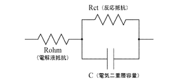
図3は、二次電池14の電気的等価回路の一例を示す図である。この例では、等価回路は、電解液抵抗(または導電抵抗)Rohmに対して、並列接続された反応抵抗Rctおよび電気二重層容量Cが直列接続されている。制御部10のCPU10aは、このような等価回路のパラメータ(素子値)を、例えば、カルマンフィルタまたはサポートベクタマシン等のアルゴリズムを用いて学習処理する。CPU10aは、学習処理によって得られた等価回路のパラメータを、RAM10cにパラメータ10caとして格納する。
FIG. 3 is a diagram illustrating an example of an electrical equivalent circuit of the secondary battery 14. In this example, in the equivalent circuit, a reaction resistance Rct and an electric double layer capacitance C connected in parallel are connected in series to an electrolyte resistance (or conductive resistance) Rohm. The CPU 10a of the
なお、図3に示す等価回路は一例であって、反応抵抗と電気二重層容量が2つ以上存在してもよい。また、電気二重層容量を有しない抵抗だけの構成としてもよい。 Note that the equivalent circuit shown in FIG. 3 is an example, and two or more reaction resistors and electric double layer capacities may exist. Moreover, it is good also as a structure only of the resistor which does not have an electric double layer capacity | capacitance.
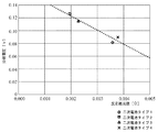
RAM10cには、等価回路の素子値と分極電圧値との関係を示す情報(例えば、関係式)が、二次電池14のSOCの値毎に格納されている。図4は、SOCが100%の場合における反応抵抗値Rctと分極電圧値V_SOEとの関係を示す図である。この図において、菱形および四角形は初期容量が異なる2つの二次電池(二次電池タイプ1および二次電池タイプ2)の実測値を示し、三角形とクロスは容量が同じで製造メーカが異なる2つの二次電池(二次電池タイプ3および二次電池タイプ4)の実測値を示している。破線は、これらの実測値から、例えば、最小二乗法によって求めた関係式を示している。また、図5は、SOCが80%の場合における反応抵抗値Rctと分極電圧値V_SOEとの関係を示す図である。この図において、実測値は図4の場合と同様であり、破線はこれらの実測値から、例えば、最小二乗法によって求めた関係式を示している。図4および図5に示すように、反応抵抗値と分極電圧値との間には二次電池の初期容量や製造メーカによらず一定の関係が存在している。すなわち、反応抵抗値が大きくなると、分極電圧値が小さくなる関係が存在する。
In the RAM 10c, information (for example, a relational expression) indicating the relationship between the element value of the equivalent circuit and the polarization voltage value is stored for each SOC value of the secondary battery 14. FIG. 4 is a diagram showing the relationship between the reaction resistance value Rct and the polarization voltage value V_SOE when the SOC is 100%. In this figure, diamonds and squares show measured values of two secondary batteries (
なお、図4および図5に示す実測値は、例えば、つぎのような方法によって求めることができる。すなわち、測定対象の二次電池のSOCが100%で、温度が25℃である場合に、二次電池を目的のSOCよりも5%低い状態になるように調整放電させるとともに、その際の電圧値および電流値を測定する。つぎに、目標のSOCになるように、SOCを5%充電し、その際の電流値および電圧値を測定する。例えば、目標SOCが80%である場合には、75%(=80%−5%)になるように調整放電させた後、5%充電する。そして、充電終了から1時間が経過した際の二次電池の端子電圧を測定し、測定値をOCV1とする。つぎに、調整放電中および充電中の電流値を積算して得られる積算電流値を、調整放電開始前のSOCの値である100%に加算し、真のSOCを求める。そして求めたSOCを、SOCとOCVの関係を示す式(例えば、一次関数)に代入し、得られた開回路電圧値をOCV2とし、OCV1およびOCV2の差分値から分極電圧値V_SOE(=OCV1−OCV2)を求める。そして、そのときの二次電池の等価回路を求め、求めた等価回路の反応抵抗値Rctと、分極電圧値V_SOEを測定結果とする。このようにして求めた反応抵抗値Rctと、分極電圧値V_SOEとの関係を示す情報は、例えば、数式(例えば、一次関数)として、SOC毎にRAM10cに格納する。 Note that the actual measurement values shown in FIGS. 4 and 5 can be obtained by the following method, for example. That is, when the SOC of the secondary battery to be measured is 100% and the temperature is 25 ° C., the secondary battery is adjusted and discharged so as to be 5% lower than the target SOC, and the voltage at that time Measure the value and current value. Next, the SOC is charged 5% so as to achieve the target SOC, and the current value and voltage value at that time are measured. For example, when the target SOC is 80%, the battery is charged at 5% after adjusting discharge to 75% (= 80% -5%). Then, the terminal voltage of the secondary battery when 1 hour has elapsed since the end of charging is measured, and the measured value is OCV1. Next, the integrated current value obtained by integrating the current values during the regulated discharge and during charging is added to 100%, which is the SOC value before the start of the regulated discharge, to obtain the true SOC. Then, the obtained SOC is substituted into an expression (for example, a linear function) indicating the relationship between SOC and OCV, and the obtained open circuit voltage value is defined as OCV2, and the polarization voltage value V_SOE (= OCV1- OCV2). Then, an equivalent circuit of the secondary battery at that time is obtained, and the reaction resistance value Rct and the polarization voltage value V_SOE of the obtained equivalent circuit are used as measurement results. Information indicating the relationship between the reaction resistance value Rct thus obtained and the polarization voltage value V_SOE is stored in the RAM 10c for each SOC, for example, as an equation (for example, a linear function).
CPU10aは、以上のようにして測定されて格納されている数式をRAM10cから取得する。例えば、SOCが80%である場合には、図5の破線に対応する数式をRAM10cから取得する。そして、学習処理によって求めた反応抵抗値RctをRAM10cから取得し、取得した反応抵抗値Rctから、分極電圧値を求める。例えば、SOCが80%であり、反応抵抗値が0.002である場合には図5の破線から分極電圧として約0.12Vを得ることができる。 The CPU 10a acquires the mathematical formula measured and stored as described above from the RAM 10c. For example, when the SOC is 80%, a mathematical expression corresponding to the broken line in FIG. 5 is acquired from the RAM 10c. And the reaction resistance value Rct calculated | required by the learning process is acquired from RAM10c, and a polarization voltage value is calculated | required from the acquired reaction resistance value Rct. For example, when the SOC is 80% and the reaction resistance value is 0.002, about 0.12 V can be obtained as the polarization voltage from the broken line in FIG.
CPU10aは、以上のようにして求めた分極電圧値V_SOEを、その時点における二次電池14の端子電圧値Vから減算することで、開回路電圧値OCV(=V−V_SOE)を得ることができる。以上のような方法によって開回路電圧値OCVを求めることで、イグニッションスイッチがオフされてから短い時間で開回路電圧値OCVを求めることができる。すなわち、二次電池14の分極電圧は、図6に示すように、非常に長い時間をかけて解消される。図6の例では、一点鎖線で示すタイプAの二次電池の分極電圧Aおよび実線で示すタイプBの二次電池の分極電圧Bは、10時間以上の時間をかけて解消される。開回路電圧は、分極電圧が解消された状態における二次電池の端子電圧であるので、正確な開回路電圧を求めるためには、分極電圧が解消された後に測定する必要があるが、前述のように、分極電圧が解消されるためには非常に長い時間を必要とする。本実施形態では、図4および図5に示すような、反応抵抗値と分極電圧値の関係を求めておき、このような関係を用いて、二次電池の開回路電圧を求めることで、例えば、イグニッションスイッチがオフされてから短い時間(例えば、1時間)であっても、開回路電圧を正確に求めることができる。また、図4および図5に示すように、反応抵抗値と分極電圧値との関係式は、二次電池の初期容量や製造メーカ等によらず成立することから、二次電池の初期容量や製造メーカによらず、正確な開回路電圧を求めることができる。 The CPU 10a can obtain the open circuit voltage value OCV (= V−V_SOE) by subtracting the polarization voltage value V_SOE obtained as described above from the terminal voltage value V of the secondary battery 14 at that time. . By obtaining the open circuit voltage value OCV by the method as described above, the open circuit voltage value OCV can be obtained in a short time after the ignition switch is turned off. That is, the polarization voltage of the secondary battery 14 is eliminated over a very long time as shown in FIG. In the example of FIG. 6, the polarization voltage A of the type A secondary battery indicated by the alternate long and short dash line and the polarization voltage B of the type B secondary battery indicated by the solid line are eliminated over 10 hours or more. Since the open circuit voltage is a terminal voltage of the secondary battery in a state where the polarization voltage is eliminated, in order to obtain an accurate open circuit voltage, it is necessary to measure after the polarization voltage is eliminated. As described above, a very long time is required to eliminate the polarization voltage. In this embodiment, the relationship between the reaction resistance value and the polarization voltage value as shown in FIG. 4 and FIG. 5 is obtained, and by using such a relationship, the open circuit voltage of the secondary battery is obtained, for example, The open circuit voltage can be accurately obtained even in a short time (for example, 1 hour) after the ignition switch is turned off. Further, as shown in FIGS. 4 and 5, since the relational expression between the reaction resistance value and the polarization voltage value is established regardless of the initial capacity of the secondary battery or the manufacturer, the initial capacity of the secondary battery or An accurate open circuit voltage can be obtained regardless of the manufacturer.
なお、以上の説明では、二次電池14の温度については考慮していないが、二次電池14の温度に応じて、得られた分極電圧値V_SOEを補正するようにしてもよい。図7は、温度による分極電圧の解消の相違を示している。実線は二次電池14の温度が65℃の場合の分極電圧の解消の様子を示し、間隔が長い破線は温度が25℃の場合の分極電圧の解消の様子を示し、間隔が短い破線は温度が−10℃の場合の分極電圧の解消の様子を示している。この例では、温度が25℃の場合が最も早く解消し、温度が高い場合および低い場合には解消の速度が遅くなっている。そこで、例えば、温度による分極電圧値に基づいて補正係数を求め、この補正係数を分極電圧値に乗算することで、温度補正を行うようにしてもよい。 In the above description, the temperature of the secondary battery 14 is not considered, but the obtained polarization voltage value V_SOE may be corrected according to the temperature of the secondary battery 14. FIG. 7 shows the difference in elimination of the polarization voltage due to temperature. The solid line shows the state of elimination of the polarization voltage when the temperature of the secondary battery 14 is 65 ° C., the broken line with a long interval shows the state of elimination of the polarization voltage when the temperature is 25 ° C., and the broken line with a short interval shows the temperature Shows the state of elimination of the polarization voltage when -10 ° C. In this example, the case where the temperature is 25 ° C. is resolved earliest, and when the temperature is high and low, the resolution is slow. Therefore, for example, a temperature correction may be performed by obtaining a correction coefficient based on a polarization voltage value depending on temperature and multiplying the polarization voltage value by this correction coefficient.
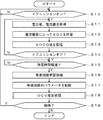
つぎに、図8および図9を参照して、本実施形態において実行される処理の詳細について説明する。図8は、本実施形態において実行される処理の一例を説明するためのフローチャートである。この処理が開始されると、以下のステップが実行される。 Next, details of processing executed in the present embodiment will be described with reference to FIGS. 8 and 9. FIG. 8 is a flowchart for explaining an example of processing executed in the present embodiment. When this process is started, the following steps are executed.
ステップS10では、CPU10aは、図示しないイグニッションスイッチが運転者によってオンの状態にされたか否かを判定し、オンの状態にされたと判定した場合(ステップS10:Yes)にはステップS11に進み、それ以外の場合(ステップS10:No)には同様の処理を繰り返す。例えば、運転者が車両に乗車し、図示しないイグニッションスイッチを操作してオンの状態にした場合にはYesと判定してステップS11に進む。 In step S10, the CPU 10a determines whether or not an unillustrated ignition switch has been turned on by the driver. If it is determined that the ignition switch has been turned on (step S10: Yes), the process proceeds to step S11. In other cases (step S10: No), the same processing is repeated. For example, if the driver gets on the vehicle and operates an ignition switch (not shown) to turn it on, the determination is Yes and the process proceeds to step S11.
ステップS11では、CPU10aは、電圧センサ11および電流センサ12の出力を参照し、二次電池14の端子電圧の電圧値および二次電池14に流れる充放電電流値を取得する。
In step S11, the CPU 10a refers to the outputs of the
ステップS12では、CPU10aは、ステップS11で取得した電流値を、後述する処理によってある時点で求めたSOCの値に累積加算することで、その時点におけるSOCの値を求める。より詳細には、例えば、ステップS18の処理によって求めたOCVの値を、SOCとOCVの関係を示す式(例えば、一次式)に代入することでSOCを求める。そして、このSOCに対して、ステップS11で求めた電流値を累積加算することで、その時点における最新のSOCの値を求める。 In step S12, the CPU 10a obtains the SOC value at that time by cumulatively adding the current value obtained in step S11 to the SOC value obtained at a certain time by the process described later. More specifically, for example, the SOC is obtained by substituting the value of OCV obtained by the processing of step S18 into an expression (for example, a primary expression) indicating the relationship between the SOC and the OCV. Then, the current value obtained in step S11 is cumulatively added to this SOC to obtain the latest SOC value at that time.
ステップS13では、CPU10aは、ステップS12で求めたSOCの値を、RAM10cに格納する。 In step S13, the CPU 10a stores the SOC value obtained in step S12 in the RAM 10c.
ステップS14では、CPU10aは、図示しないイグニッションスイッチが運転者によってオフの状態にされたか否かを判定し、オフの状態にされたと判定した場合(ステップS14:Yes)にはステップS15に進み、それ以外の場合(ステップS14:No)にはステップS11に戻って前述の場合と同様の処理を繰り返す。例えば、運転者が車両を停車し、図示しないイグニッションスイッチを操作してオフの状態にした場合にはYesと判定してステップS15に進む。 In step S14, the CPU 10a determines whether or not an unillustrated ignition switch has been turned off by the driver. If it is determined that the ignition switch has been turned off (step S14: Yes), the process proceeds to step S15. In other cases (step S14: No), the process returns to step S11 and the same process as described above is repeated. For example, if the driver stops the vehicle and operates an ignition switch (not shown) to turn it off, the determination is Yes and the process proceeds to step S15.
ステップS15では、CPU10aは、イグニッションスイッチがオフの状態にされてから所定の時間(例えば、1時間)が経過したか否かを判定し、所定の時間が経過したと判定した場合(ステップS15:Yes)にはステップS16に進み、それ以外の場合(ステップS15:No)には同様の処理を繰り返す。例えば、イグニッションスイッチがオフの状態にされてから1時間が経過した場合にはYesと判定してステップS16に進む。 In step S15, the CPU 10a determines whether or not a predetermined time (for example, 1 hour) has elapsed since the ignition switch was turned off, and determines that the predetermined time has elapsed (step S15: If yes, the process proceeds to step S16, otherwise the same process is repeated (step S15: No). For example, if one hour has elapsed since the ignition switch was turned off, the determination is Yes and the process proceeds to step S16.
ステップS16では、CPU10aは、放電回路15を制御して、所定の周期および所定の電流値で二次電池14をパルス放電させ、そのときの電圧値および電流値を電圧センサ11および電流センサ12の出力を参照して検出し、二次電池14の等価回路の素子値を学習する処理を実行する。より詳細には、CPU10aは、図3に示す等価回路を構成する各素子の素子値を、例えば、カルマンフィルタまたはサポートベクタマシン等のアルゴリズムを用いて検出した電圧値および電流値に基づいて学習処理する。
In step S <b> 16, the CPU 10 a controls the
ステップS17では、CPU10aは、ステップS16の学習処理によって得られた等価回路の素子値を、RAM10cにパラメータ10caとして格納する。 In step S17, the CPU 10a stores the element value of the equivalent circuit obtained by the learning process in step S16 in the RAM 10c as the parameter 10ca.
ステップS18では、CPU10aは、OCVを推定する処理を実行する。その結果、正確なOCVを求めることができる。なお、この処理の詳細については、図9を参照して後述する。 In step S18, the CPU 10a executes a process for estimating the OCV. As a result, an accurate OCV can be obtained. Details of this process will be described later with reference to FIG.
ステップS19では、CPU10aは、処理を継続するか否かを判定し、継続すると判定した場合(ステップS19:Yes)にはステップS10に戻って前述の場合と同様の処理を繰り返し、それ以外の場合(ステップS19:No)には処理を終了する。 In step S19, the CPU 10a determines whether or not to continue the process. If it is determined that the process is to be continued (step S19: Yes), the process returns to step S10 and the same process as described above is repeated. In step S19: No, the process ends.
つぎに、図9を参照して、図8のステップS18に示すOCV推定処理の詳細について説明する。 Next, the OCV estimation process shown in step S18 of FIG. 8 will be described in detail with reference to FIG.
ステップS30では、CPU10aは、図8のステップS13においてRAM10cに格納したSOCの値を取得する。例えば、SOCの値として80%が取得される。 In step S30, the CPU 10a acquires the SOC value stored in the RAM 10c in step S13 of FIG. For example, 80% is acquired as the SOC value.
ステップS31では、CPU10aは、温度センサ13の出力を参照し、二次電池14の温度を取得する。例えば、二次電池14の温度として、30℃が取得される。
In step S31, the CPU 10a refers to the output of the
ステップS32では、CPU10aは、ステップS30で取得したSOC値に対応する関係式(反応抵抗値と分極電圧値の関係を示す式)をRAM10cから取得する。いまの例では、SOCの値は80%であることから、例えば、図5に示す破線に対応する関係式が取得される。 In step S32, the CPU 10a acquires from the RAM 10c a relational expression (an expression indicating a relation between the reaction resistance value and the polarization voltage value) corresponding to the SOC value acquired in step S30. In the present example, since the SOC value is 80%, for example, the relational expression corresponding to the broken line shown in FIG. 5 is acquired.
ステップS33では、CPU10aは、ステップS15で格納した反応抵抗値RctをRAM10cから取得する。例えば、反応抵抗値Rctとして0.002Ωが取得される。 In step S33, the CPU 10a acquires the reaction resistance value Rct stored in step S15 from the RAM 10c. For example, 0.002Ω is acquired as the reaction resistance value Rct.
ステップS34では、CPU10aは、ステップS32で取得した関係式に対して、ステップS33で取得した反応抵抗値Rctを適用し、分極電圧値V_SOEを求める。いまの例では、図5の破線に対応する関係式に、反応抵抗値Rctとして0.002Ωを適用することで、分極電圧値V_SOEとして0.12Vを得る。 In step S34, the CPU 10a applies the reaction resistance value Rct acquired in step S33 to the relational expression acquired in step S32 to obtain the polarization voltage value V_SOE. In the present example, by applying 0.002Ω as the reaction resistance value Rct to the relational expression corresponding to the broken line in FIG. 5, 0.12 V is obtained as the polarization voltage value V_SOE.
ステップS35では、CPU10aは、ステップS34で求めた分極電圧値V_SOEを、ステップS31で取得した温度に応じて補正する処理を実行する。より詳細には、図7に示す温度特性から温度補正係数を求め、温度と温度補正係数の対応関係を示す関係式またはテーブルをRAM10cに格納しておく。そして、ステップS31で取得した温度に対応する温度補正係数を取得して、分極電圧値V_SOEに乗算することで、温度補正を行うことができる。いまの例では、温度は30℃であるので、例えば、温度補正係数として1.25を得たとすると、補正後の分極電圧値として0.15V(=0.12×1.25)を得る。 In step S35, the CPU 10a executes a process of correcting the polarization voltage value V_SOE obtained in step S34 according to the temperature obtained in step S31. More specifically, a temperature correction coefficient is obtained from the temperature characteristics shown in FIG. 7, and a relational expression or table indicating a correspondence relationship between the temperature and the temperature correction coefficient is stored in the RAM 10c. Then, temperature correction can be performed by acquiring a temperature correction coefficient corresponding to the temperature acquired in step S31 and multiplying the polarization voltage value V_SOE. In this example, since the temperature is 30 ° C., for example, if 1.25 is obtained as the temperature correction coefficient, 0.15 V (= 0.12 × 1.25) is obtained as the polarization voltage value after correction.
ステップS36では、CPU10aは、電圧センサ11の出力を参照し、二次電池14のその時点における電圧値Vを取得する。例えば、その時点の電圧として、12.5Vを得る。
In step S36, the CPU 10a refers to the output of the
ステップS37では、CPU10aは、ステップS36で求めた電圧値Vから、ステップS35で温度補正した分極電圧値V_SOEを減算することで、開回路電圧値OCV(=V−V_SOE)を得る。例えば、いまの例では、ステップS36で求めた電圧値12.5Vから、ステップS35で温度補正した分極電圧値0.15Vを減算することで開回路電圧値として12.35V(=12.5−0.15)を得る。 In step S37, the CPU 10a obtains the open circuit voltage value OCV (= V−V_SOE) by subtracting the polarization voltage value V_SOE corrected in temperature in step S35 from the voltage value V obtained in step S36. For example, in this example, the open circuit voltage value is 12.35 V (= 12.5−) by subtracting the polarization voltage value 0.15 V, which is temperature-corrected in step S35, from the voltage value 12.5 V obtained in step S36. 0.15) is obtained.
以上の処理によれば、反応抵抗値Rctと分極電圧値V_SOEとの関係式に基づいて、分極電圧値V_SOEを求め、求めた分極電圧値V_SOEからOCVを求めるようにしたので、例えば、イグニッションスイッチがオフされてから短時間でOCVを正確に求めることができる。また、反応抵抗値Rctと分極電圧値V_SOEとの関係式は、二次電池14の初期容量や製造メーカによらず成立するので、二次電池14の種類によらず、OCVを正確に求めることができる。また、以上の実施形態では、温度補正係数によって分極電圧値V_SOEを補正するようにしたので、二次電池14の温度によらず正確な分極電圧値V_SOEを求めることができる。 According to the above processing, the polarization voltage value V_SOE is obtained based on the relational expression between the reaction resistance value Rct and the polarization voltage value V_SOE, and the OCV is obtained from the obtained polarization voltage value V_SOE. The OCV can be accurately obtained in a short time after is turned off. Further, since the relational expression between the reaction resistance value Rct and the polarization voltage value V_SOE is established regardless of the initial capacity of the secondary battery 14 and the manufacturer, the OCV can be accurately obtained regardless of the type of the secondary battery 14. Can do. In the above embodiment, since the polarization voltage value V_SOE is corrected by the temperature correction coefficient, the accurate polarization voltage value V_SOE can be obtained regardless of the temperature of the secondary battery 14.
(C)変形実施形態の説明
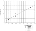
以上の実施形態は一例であって、本発明が上述したような場合のみに限定されるものでないことはいうまでもない。例えば、以上の実施形態では、等価回路を構成する反応抵抗のみを用いて分極電圧値V_SOEを求めるようにしたが、これ以外にも、例えば、電解液抵抗(または導電抵抗)、電気二重層容量、または、拡散抵抗素子(反応抵抗素子に含まれる抵抗素子)を用いるようにしてもよい。図10は、SOCが100%で温度が25℃の場合における電解液抵抗値と分極電圧値との関係を示す図である。また、図11は、SOCが80%で温度が25℃の場合における電解液抵抗値と分極電圧値との関係を示す図である。なお、これらの図において、横軸は電解液抵抗値(Ω)を示し、縦軸は分極電圧値(V)を示す。これらの図に示すように、電解液抵抗値と分極電圧値との間にも、反応抵抗値と同様の関係が存在している。このため、反応抵抗値に代えて電解液抵抗を用いた場合でも、前述の場合と同様の効果を得ることができる。
(C) Description of Modified Embodiment It goes without saying that the above embodiment is merely an example, and the present invention is not limited to the case described above. For example, in the above embodiment, the polarization voltage value V_SOE is obtained using only the reaction resistance constituting the equivalent circuit, but other than this, for example, the electrolyte resistance (or conductive resistance), the electric double layer capacitance, etc. Alternatively, a diffusion resistance element (a resistance element included in the reaction resistance element) may be used. FIG. 10 is a diagram showing the relationship between the electrolyte resistance value and the polarization voltage value when the SOC is 100% and the temperature is 25 ° C. FIG. 11 is a diagram showing the relationship between the electrolytic solution resistance value and the polarization voltage value when the SOC is 80% and the temperature is 25 ° C. In these figures, the horizontal axis represents the electrolyte resistance value (Ω), and the vertical axis represents the polarization voltage value (V). As shown in these figures, a relationship similar to the reaction resistance value also exists between the electrolyte resistance value and the polarization voltage value. For this reason, even when the electrolytic solution resistance is used instead of the reaction resistance value, the same effect as described above can be obtained.
図12は、SOCが100%で温度が25℃の場合における電気二重層容量値と分極電圧値との関係を示す図である。また、図13は、SOCが80%で温度が25℃の場合における電気二重層容量値と分極電圧値との関係を示す図である。なお、これらの図において、横軸は電気二重層容量値(F)を示し、縦軸は分極電圧値(V)を示す。これらの図に示すように、電気二重層容量値と分極電圧値との間にも、反応抵抗値と同様の関係が存在している。このため、反応抵抗値に代えて電気二重層容量値を用いた場合でも、前述の場合と同様の効果を得ることができる。 FIG. 12 is a diagram showing the relationship between the electric double layer capacitance value and the polarization voltage value when the SOC is 100% and the temperature is 25 ° C. FIG. 13 is a diagram showing the relationship between the electric double layer capacitance value and the polarization voltage value when the SOC is 80% and the temperature is 25 ° C. In these drawings, the horizontal axis represents the electric double layer capacitance value (F), and the vertical axis represents the polarization voltage value (V). As shown in these figures, a relationship similar to the reaction resistance value also exists between the electric double layer capacitance value and the polarization voltage value. For this reason, even when the electric double layer capacitance value is used instead of the reaction resistance value, the same effect as described above can be obtained.
なお、等価回路を構成する単一の素子を用いるのではなく、これらを複数組み合わせて使用するようにしてもよい。一例として、2つ組み合わせの場合には、反応抵抗値および電気二重層容量値と、分極電圧値V_SOEとの関係式を求め、この関係式に基づいて分極電圧値V_SOEを求めるようにしてもよい。もちろん、これら以外の組み合わせであったり、3つの組み合わせであったりしてもよい。また、複数の素子値に対して、重み付け係数を乗算して得られた値と、分極電圧値V_SOEとの関係式を求め、この関係式に基づいて分極電圧値V_SOEを求めるようにしてもよい。 Instead of using a single element constituting an equivalent circuit, a plurality of these elements may be used in combination. As an example, in the case of a combination of the two, a relational expression between the reaction resistance value, the electric double layer capacitance value, and the polarization voltage value V_SOE may be obtained, and the polarization voltage value V_SOE may be obtained based on this relational expression. . Of course, it may be a combination other than these, or a combination of three. Further, a relational expression between a value obtained by multiplying a plurality of element values by a weighting coefficient and the polarization voltage value V_SOE may be obtained, and the polarization voltage value V_SOE may be obtained based on this relational expression. .
また、以上の例では、図4および図5に示すように、SOCが100%と80%の場合を例に挙げて説明したが、これ以外のSOCの値に関する関係式をRAM10cに準備し、それらの関係式も用いて分極電圧値を求めるようにしてもよい。例えば、SOC値が60%から100%までの関係式を5%単位で準備し、その時点におけるSOC値が最も近い関係式を選択して用いるようにしてもよい。あるいは、その時点におけるSOC値が近い関係式を2つ選択し、これらの関係式を補間することによって、その時点におけるSOC値に対応する分極電圧値を求めるようにしてもよい。 In the above example, as shown in FIG. 4 and FIG. 5, the case where the SOC is 100% and 80% has been described as an example, but other relational expressions relating to the SOC value are prepared in the RAM 10c, You may make it obtain | require a polarization voltage value also using those relational expressions. For example, a relational expression with an SOC value of 60% to 100% may be prepared in units of 5%, and a relational expression with the closest SOC value at that time may be selected and used. Alternatively, two relational expressions having close SOC values at that time may be selected, and a polarization voltage value corresponding to the SOC value at that time may be obtained by interpolating these relational expressions.
また、図4および図5の比較から明らかなように、SOC値が小さい場合の方が、大きい場合に比較して、破線と実測値との誤差が少ないことから、異なるSOC値に対応する測定値が存在する場合には、SOC値が小さい場合の測定値を優先して用いるようにしてもよい。そのような方法によれば、分極電圧値をより正確に求めることができる。 As is clear from the comparison between FIG. 4 and FIG. 5, since the error between the broken line and the actual measurement value is smaller when the SOC value is smaller than when the SOC value is large, measurement corresponding to different SOC values is possible. If a value exists, the measured value when the SOC value is small may be used preferentially. According to such a method, the polarization voltage value can be obtained more accurately.
また、図8のステップS18に示すOCV推定処理については、イグニッションスイッチがオフされてから1時間経過した後に実行されるようにしたが、1時間以外の時間に設定するようにしてもよい。 Further, the OCV estimation process shown in step S18 of FIG. 8 is executed after one hour has elapsed since the ignition switch was turned off, but may be set to a time other than one hour.
また、図9に示す処理では、求めた分極電圧値を、温度係数を用いて補正するようにしたが、例えば、SOC値と温度値の双方に対応する関係式を求めておき、この関係式を用いることで温度に対する特性を加味するようにしてもよい。具体的には、SOCが80%の図5に示す関係式を、温度が0℃から50℃まで5℃単位で求め、その時点の温度とSOCに基づいて関係式を選択するようにしてもよい。 In the process shown in FIG. 9, the obtained polarization voltage value is corrected using the temperature coefficient. For example, a relational expression corresponding to both the SOC value and the temperature value is obtained, and this relational expression is obtained. May be used in consideration of the temperature characteristics. Specifically, the relational expression shown in FIG. 5 with an SOC of 80% is obtained in units of 5 ° C. from 0 ° C. to 50 ° C., and the relational expression is selected based on the temperature and SOC at that time. Good.
また、図4および図5に示す関係は、二次電池14の劣化により若干変化する場合も想定されるので、経年変化による劣化に応じた関係式を準備しておき、二次電池14の経年変化(例えば、SOH(State of Health))に応じた関係式を用いて分極電圧値を求めるようにしてもよい。 4 and 5 may be slightly changed due to deterioration of the secondary battery 14. Therefore, a relational expression corresponding to deterioration due to aging is prepared, and the aging of the secondary battery 14 is prepared. The polarization voltage value may be obtained using a relational expression corresponding to a change (for example, SOH (State of Health)).
また、以上の実施形態では、反応抵抗値Rctと分極電圧値V_SOEの関係を示す関係式を用いる場合を例に挙げて説明したが、関係式の代わりに、これらの対応関係を示す数値を格納したテーブルを用いるようにしてもよい。 In the above embodiment, the case where the relational expression indicating the relation between the reaction resistance value Rct and the polarization voltage value V_SOE is used as an example has been described. The table may be used.
また、以上の実施形態では、二次電池14の等価回路としては、図3に示す等価回路を用いるようにしたが、これ以外の等価回路を用いるようにしてもよい。例えば、並列接続される反応抵抗と電気二重層容量の数が2つ以上であってもよい。また、電気二重容量を有しない抵抗だけの等価回路を用いるようにしてもよい。 In the above embodiment, as the equivalent circuit of the secondary battery 14, the equivalent circuit shown in FIG. 3 is used. However, other equivalent circuits may be used. For example, the number of reaction resistors and electric double layer capacities connected in parallel may be two or more. Further, an equivalent circuit having only a resistor having no electric double capacitance may be used.
1 二次電池状態検出装置
10 制御部(算出手段、求出手段、計算手段)
10a CPU
10b ROM
10c RAM(格納手段)
10d 通信部
10e I/F
11 電圧センサ
12 電流センサ
13 温度センサ
14 二次電池
15 放電回路
16 オルタネータ
17 エンジン
18 スタータモータ
19 負荷
DESCRIPTION OF
10a CPU
10b ROM
10c RAM (storage means)
10d Communication unit 10e I / F
DESCRIPTION OF
Claims (6)
前記二次電池の等価回路の素子値と、前記二次電池の分極電圧値との関係を示す情報を格納する格納手段と、
前記二次電池の等価回路の素子値を算出する算出手段と、
前記算出手段によって算出された前記素子値を、前記格納手段に格納されている前記情報に適用することで、前記分極電圧値を求出する求出手段と、
前記二次電池の端子電圧値から、前記求出手段によって求出された前記分極電圧値を減算することで、開回路電圧値を計算する計算手段と、
を有することを特徴とする二次電池状態検出装置。 In a secondary battery state detection device that detects the state of a secondary battery mounted on a vehicle,
Storage means for storing information indicating a relationship between an element value of an equivalent circuit of the secondary battery and a polarization voltage value of the secondary battery;
Calculating means for calculating an element value of an equivalent circuit of the secondary battery;
Applying the element value calculated by the calculating means to the information stored in the storage means, thereby obtaining the polarization voltage value;
Calculating means for calculating an open circuit voltage value by subtracting the polarization voltage value obtained by the obtaining means from a terminal voltage value of the secondary battery;
A secondary battery state detection device comprising:
前記求出手段は、前記電解液抵抗値、前記反応抵抗値、前記電気二重層容量値、または、前記拡散抵抗値の少なくとも1つと、前記分極電圧値との関係を示す情報に基づいて前記分極電圧値を求出する、
ことを特徴とする請求項1に記載の二次電池状態検出装置。 The storage means stores information indicating a relationship between the polarization voltage value and at least one of an electrolyte resistance value, a reaction resistance value, an electric double layer capacitance value, or a diffusion resistance value constituting the equivalent circuit. And
The obtaining means includes the polarization voltage value based on information indicating a relationship between at least one of the electrolyte resistance value, the reaction resistance value, the electric double layer capacitance value, or the diffusion resistance value and the polarization voltage value. Find the voltage value,
The secondary battery state detection device according to claim 1.
前記求出手段は、前記二次電池の前記充電率に対応する情報を前記格納手段から取得して前記分極電圧値を求出する、
ことを特徴とする請求項2に記載の二次電池状態検出装置。 The storage means stores information indicating the relationship between the element value and the polarization voltage value for each charging rate of the secondary battery,
The obtaining means obtains the polarization voltage value by obtaining information corresponding to the charging rate of the secondary battery from the storage means.
The secondary battery state detection device according to claim 2.
前記二次電池の等価回路の素子値と、前記二次電池の分極電圧値との関係を示す情報を格納部に格納する格納ステップと、
前記二次電池の等価回路の素子値を算出する算出ステップと、
前記算出ステップにおいて求出された前記素子値を、前記格納部に格納されている前記情報に適用することで、前記分極電圧値を求出する求出ステップと、
前記二次電池の端子電圧値から、前記求出ステップにおいて求出された前記分極電圧値を減算することで、開回路電圧値を計算する計算ステップと、
を有することを特徴とする二次電池状態検出方法。
In a secondary battery state detection method for detecting a state of a secondary battery mounted on a vehicle,
A storage step of storing information indicating a relationship between an element value of an equivalent circuit of the secondary battery and a polarization voltage value of the secondary battery in a storage unit;
A calculation step of calculating an element value of an equivalent circuit of the secondary battery;
A step of obtaining the polarization voltage value by applying the element value obtained in the calculation step to the information stored in the storage unit;
A calculation step of calculating an open circuit voltage value by subtracting the polarization voltage value obtained in the obtaining step from the terminal voltage value of the secondary battery;
A secondary battery state detection method comprising:
Priority Applications (1)
| Application Number | Priority Date | Filing Date | Title |
|---|---|---|---|
| JP2014244537A JP6498920B2 (en) | 2014-12-02 | 2014-12-02 | Secondary battery state detection device and secondary battery state detection method |
Applications Claiming Priority (1)
| Application Number | Priority Date | Filing Date | Title |
|---|---|---|---|
| JP2014244537A JP6498920B2 (en) | 2014-12-02 | 2014-12-02 | Secondary battery state detection device and secondary battery state detection method |
Publications (2)
| Publication Number | Publication Date |
|---|---|
| JP2016109466A JP2016109466A (en) | 2016-06-20 |
| JP6498920B2 true JP6498920B2 (en) | 2019-04-10 |
Family
ID=56123846
Family Applications (1)
| Application Number | Title | Priority Date | Filing Date |
|---|---|---|---|
| JP2014244537A Active JP6498920B2 (en) | 2014-12-02 | 2014-12-02 | Secondary battery state detection device and secondary battery state detection method |
Country Status (1)
| Country | Link |
|---|---|
| JP (1) | JP6498920B2 (en) |
Families Citing this family (6)
| Publication number | Priority date | Publication date | Assignee | Title |
|---|---|---|---|---|
| JP6756372B2 (en) * | 2016-10-06 | 2020-09-16 | 株式会社豊田自動織機 | Power storage device |
| JP6979896B2 (en) * | 2018-02-06 | 2021-12-15 | 古河電気工業株式会社 | Rechargeable battery status detector and rechargeable battery status detection method |
| JP7087936B2 (en) * | 2018-11-14 | 2022-06-21 | トヨタ自動車株式会社 | Full charge capacity estimation device |
| JP7394110B2 (en) * | 2019-02-28 | 2023-12-07 | 古河電気工業株式会社 | Rechargeable battery status detection device and rechargeable battery status detection method |
| CN111025156B (en) * | 2019-12-31 | 2022-04-08 | 北方工业大学 | Battery state prediction method and device |
| CN117872167B (en) * | 2024-03-12 | 2024-05-14 | 深圳市杰维工业设备有限公司 | Battery performance influence factor analysis method |
Family Cites Families (7)
| Publication number | Priority date | Publication date | Assignee | Title |
|---|---|---|---|---|
| JP3121732B2 (en) * | 1994-11-04 | 2001-01-09 | 三菱電機株式会社 | Secondary battery parameter measurement method, secondary battery charge / discharge control method and life prediction method using the same, secondary battery charge / discharge control device, and power storage device using the same |
| JP4052418B2 (en) * | 2000-02-15 | 2008-02-27 | 日立マクセル株式会社 | Battery capacity detection method and apparatus, and battery pack |
| JP2002056903A (en) * | 2000-08-07 | 2002-02-22 | Hitachi Ltd | Polarization voltage value computing method, battery voltage value compensation method and remainder state estimation method of secondary battery, secondary battery unit and device using same |
| WO2005013409A1 (en) * | 2003-07-02 | 2005-02-10 | Eaton Power Quality Limited | Battery float management |
| JP4074596B2 (en) * | 2004-03-18 | 2008-04-09 | 日立マクセル株式会社 | Rechargeable battery or rechargeable battery pack |
| JP2007179968A (en) * | 2005-12-28 | 2007-07-12 | Auto Network Gijutsu Kenkyusho:Kk | Battery status control device |
| JP2014074588A (en) * | 2012-10-02 | 2014-04-24 | Furukawa Electric Co Ltd:The | Secondary battery state detection device and secondary battery state detection method |
-
2014
- 2014-12-02 JP JP2014244537A patent/JP6498920B2/en active Active
Also Published As
| Publication number | Publication date |
|---|---|
| JP2016109466A (en) | 2016-06-20 |
Similar Documents
| Publication | Publication Date | Title |
|---|---|---|
| JP6490414B2 (en) | Secondary battery state detection device and secondary battery state detection method | |
| JP6498920B2 (en) | Secondary battery state detection device and secondary battery state detection method | |
| JP6479650B2 (en) | Secondary battery state detection device and secondary battery state detection method | |
| JP5653881B2 (en) | Secondary battery state detection device and secondary battery state detection method | |
| US10393814B2 (en) | Secondary battery state detection device and secondary battery state detection method | |
| CN108885242B (en) | Secondary battery degradation estimation device and secondary battery degradation estimation method | |
| JP6440377B2 (en) | Secondary battery state detection device and secondary battery state detection method | |
| JP6200359B2 (en) | Secondary battery internal temperature estimation device and secondary battery internal temperature estimation method | |
| WO2019230033A1 (en) | Parameter estimation device, parameter estimation method, and computer program | |
| CN109874354B (en) | Secondary battery state detection device and secondary battery state detection method | |
| JP6452403B2 (en) | Secondary battery state detection device and secondary battery state detection method | |
| JP6895786B2 (en) | Secondary battery status detection device and secondary battery status detection method | |
| JP2012189373A (en) | Secondary battery condition detection device and secondary battery condition detection method | |
| JP2022044621A (en) | Rechargeable battery liquid decrease detection device and rechargeable battery liquid decrease detection method | |
| JP6210552B2 (en) | Secondary battery state detection device and secondary battery state detection method | |
| JP6826935B2 (en) | Secondary battery internal temperature estimation device and secondary battery internal temperature estimation method | |
| JP5554310B2 (en) | Internal resistance measuring device and internal resistance measuring method | |
| JP2007261433A (en) | Battery control device and battery control method | |
| JP6979896B2 (en) | Rechargeable battery status detector and rechargeable battery status detection method | |
| JP5094480B2 (en) | Battery state estimation device and battery state estimation method | |
| JP6953323B2 (en) | Rechargeable battery status detector and rechargeable battery status detection method | |
| JP6550036B2 (en) | Secondary battery state detection device and secondary battery state detection method | |
| JP2020155394A (en) | Rechargeable battery temperature estimation device and rechargeable battery temperature estimation method | |
| JP2021150220A (en) | Method of estimating battery state, device, program, and storage medium |
Legal Events
| Date | Code | Title | Description |
|---|---|---|---|
| A621 | Written request for application examination |
Free format text: JAPANESE INTERMEDIATE CODE: A621 Effective date: 20171013 |
|
| A977 | Report on retrieval |
Free format text: JAPANESE INTERMEDIATE CODE: A971007 Effective date: 20180718 |
|
| A131 | Notification of reasons for refusal |
Free format text: JAPANESE INTERMEDIATE CODE: A131 Effective date: 20180725 |
|
| A521 | Written amendment |
Free format text: JAPANESE INTERMEDIATE CODE: A523 Effective date: 20180917 |
|
| TRDD | Decision of grant or rejection written | ||
| A01 | Written decision to grant a patent or to grant a registration (utility model) |
Free format text: JAPANESE INTERMEDIATE CODE: A01 Effective date: 20190307 |
|
| A61 | First payment of annual fees (during grant procedure) |
Free format text: JAPANESE INTERMEDIATE CODE: A61 Effective date: 20190314 |
|
| R151 | Written notification of patent or utility model registration |
Ref document number: 6498920 Country of ref document: JP Free format text: JAPANESE INTERMEDIATE CODE: R151 |
|
| S531 | Written request for registration of change of domicile |
Free format text: JAPANESE INTERMEDIATE CODE: R313531 |
|
| R350 | Written notification of registration of transfer |
Free format text: JAPANESE INTERMEDIATE CODE: R350 |