JP6210552B2 - Secondary battery state detection device and secondary battery state detection method - Google Patents
Secondary battery state detection device and secondary battery state detection method Download PDFInfo
- Publication number
- JP6210552B2 JP6210552B2 JP2014042207A JP2014042207A JP6210552B2 JP 6210552 B2 JP6210552 B2 JP 6210552B2 JP 2014042207 A JP2014042207 A JP 2014042207A JP 2014042207 A JP2014042207 A JP 2014042207A JP 6210552 B2 JP6210552 B2 JP 6210552B2
- Authority
- JP
- Japan
- Prior art keywords
- secondary battery
- value
- current
- voltage
- voltage value
- Prior art date
- Legal status (The legal status is an assumption and is not a legal conclusion. Google has not performed a legal analysis and makes no representation as to the accuracy of the status listed.)
- Active
Links
Images


Classifications
-
- Y—GENERAL TAGGING OF NEW TECHNOLOGICAL DEVELOPMENTS; GENERAL TAGGING OF CROSS-SECTIONAL TECHNOLOGIES SPANNING OVER SEVERAL SECTIONS OF THE IPC; TECHNICAL SUBJECTS COVERED BY FORMER USPC CROSS-REFERENCE ART COLLECTIONS [XRACs] AND DIGESTS
- Y02—TECHNOLOGIES OR APPLICATIONS FOR MITIGATION OR ADAPTATION AGAINST CLIMATE CHANGE
- Y02E—REDUCTION OF GREENHOUSE GAS [GHG] EMISSIONS, RELATED TO ENERGY GENERATION, TRANSMISSION OR DISTRIBUTION
- Y02E60/00—Enabling technologies; Technologies with a potential or indirect contribution to GHG emissions mitigation
- Y02E60/10—Energy storage using batteries
Landscapes
- Tests Of Electric Status Of Batteries (AREA)
- Charge And Discharge Circuits For Batteries Or The Like (AREA)
- Secondary Cells (AREA)
Description
本発明は、二次電池状態検出装置および二次電池状態検出方法に関するものである。 The present invention relates to a secondary battery state detection device and a secondary battery state detection method.
特許文献1には、自動車のエンジン始動時における電流および電圧から二次電池の純抵抗成分および分極抵抗成分を計算し、これら純抵抗成分および分極抵抗成分の新品時との比較により、二次電池の劣化を判定する技術が開示されている。
In
ところで、二次電池のSOC(State of Charge)またはSOH(State of Health)を精度良く求めるためには、分極電圧または分極量および成層化電圧または成層化量に基づいた補正を行う必要があり、このような補正を行うための係数は、二次電池のサイズ(初期満充電容量)によって異なる。特許文献1に示すような従来の技術では、予め定められたサイズの二次電池を使用することを想定し、この定められたサイズの二次電池に応じた補正係数を用いて補正を行っていた。
By the way, in order to accurately determine the SOC (State of Charge) or SOH (State of Health) of the secondary battery, it is necessary to perform correction based on the polarization voltage or polarization amount and the stratification voltage or stratification amount. The coefficient for performing such correction varies depending on the size (initial full charge capacity) of the secondary battery. In the conventional technology as shown in
このため、予め定められたサイズとは異なる二次電池に交換された場合には、精度良く補正を行うことができないことから、二次電池の状態を正確に検出することができないという問題点がある。 For this reason, when the battery is replaced with a secondary battery having a size different from the predetermined size, the correction cannot be performed with high accuracy, so that the state of the secondary battery cannot be accurately detected. is there.
本発明は、二次電池の初期満充電容量またはサイズを推定することが可能な二次電池状態検出装置および二次電池状態検出方法を提供することを目的としている。 An object of the present invention is to provide a secondary battery state detection device and a secondary battery state detection method capable of estimating an initial full charge capacity or size of a secondary battery.
上記課題を解決するために、本発明は、車両に搭載される二次電池の状態を検出する二次電池状態検出装置において、前記二次電池に流れる電流の値および前記二次電池の電圧の値を検出する検出手段と、前記二次電池の放電前の電圧値および電流値を前記検出手段によって検出するとともに、前記二次電池の放電中の電圧値および電流値を前記検出手段によって検出し、これらの電圧値および電流値に基づいて、前記二次電池の反応抵抗に関する値を求出する求出手段と、前記求出手段によって求出された前記反応抵抗に関する値と、前記二次電池の初期満充電容量とが有する相関関係に基づいて、前記初期満充電容量を推定する推定手段と、を有することを特徴とする。
このような構成によれば、二次電池の初期満充電容量またはサイズを推定することが可能になる。
In order to solve the above-described problems, the present invention provides a secondary battery state detection device for detecting a state of a secondary battery mounted on a vehicle, wherein a value of a current flowing through the secondary battery and a voltage of the secondary battery are determined. A detecting means for detecting a value, a voltage value and a current value before discharging of the secondary battery are detected by the detecting means, and a voltage value and a current value during discharging of the secondary battery are detected by the detecting means. , Based on these voltage value and current value, a obtaining means for obtaining a value relating to the reaction resistance of the secondary battery, a value relating to the reaction resistance obtained by the obtaining means, and the secondary battery And an estimation means for estimating the initial full charge capacity based on the correlation of the initial full charge capacity.
According to such a configuration, it is possible to estimate the initial full charge capacity or size of the secondary battery.
また、本発明は、前記求出手段は、前記車両のエンジンを始動するスタータモータの回転前の電圧値および電流値を前記検出手段によって検出するとともに、前記スタータモータの回転中の前記二次電池の電圧値および電流値を前記検出手段によって検出し、これらの電圧値および電流値に基づいて、前記二次電池の反応抵抗に関する値を求出することを特徴とする。
このような構成によれば、ある程度の大きさの電流が、ある程度の時間流れるスタータモータ回転時を用いることで二次電池の初期満充電容量を安定して推定することが可能になる。
According to the present invention, the obtaining means detects the voltage value and current value before rotation of the starter motor for starting the engine of the vehicle by the detection means, and the secondary battery during rotation of the starter motor. A voltage value and a current value of the secondary battery are detected by the detection means, and a value relating to a reaction resistance of the secondary battery is obtained based on the voltage value and the current value.
According to such a configuration, it is possible to stably estimate the initial full charge capacity of the secondary battery by using the rotation of the starter motor in which a certain amount of current flows for a certain period of time.
また、本発明は、前記求出手段は、前記二次電池の放電前の電圧値と放電中の電圧値の差分の電圧値を求めるとともに、前記二次電池の放電前の電流値と放電中の電流値の差分の電流値を求め、前記差分の電圧値を前記差分の電流値で除算して得られた値を、前記反応抵抗に関する値とすることを特徴とする。
このような構成によれば、二次電池の放電前後の電圧値および電流値に基づいて、初期満充電容量を精度良く求めることができる。
Further, according to the present invention, the obtaining means obtains a voltage value of a difference between the voltage value before the discharge of the secondary battery and the voltage value during the discharge, and the current value before the discharge of the secondary battery and the discharge of the secondary battery. A current value of a difference between the current values is obtained, and a value obtained by dividing the voltage value of the difference by the current value of the difference is set as a value related to the reaction resistance.
According to such a configuration, the initial full charge capacity can be accurately obtained based on the voltage value and current value before and after discharging of the secondary battery.
また、本発明は、前記求出手段は、前記二次電池の放電前の電圧値と放電開始直後の電圧値の差分の電圧値を求めるとともに、前記二次電池の放電前の電流値と放電開始直後の電流値の差分の電流を求め、前記差分の電圧値を前記差分の電流値で除算して得られた値を第1抵抗値とし、前記二次電池が放電前の電圧値と放電開始直後よりも後の電圧値の差分の電圧値を求めるとともに、前記二次電池の放電前の電流値と放電開始直後よりも後の電流値の差分の電流値を求め、前記差分の電圧値を前記差分の電流値で除算して得られた値を第2抵抗値とし、前記第2抵抗値から前記第1抵抗値を減算して得た値を、前記反応抵抗に関する値とすることを特徴とする。
このような構成によれば、導体抵抗の影響を低減することで、初期満充電容量をさらに精度良く求めることができる。
Further, according to the present invention, the obtaining means obtains a voltage value of a difference between the voltage value before the discharge of the secondary battery and the voltage value immediately after the start of the discharge, and the current value and the discharge before the discharge of the secondary battery. The difference current value immediately after the start is obtained, the voltage value obtained by dividing the difference voltage value by the difference current value is defined as a first resistance value, and the secondary battery is discharged from the voltage value before discharging. Obtaining the voltage value of the difference between the voltage values after immediately after the start and obtaining the current value of the difference between the current value before the discharge of the secondary battery and the current value after immediately after the start of the discharge, and the voltage value of the difference The value obtained by dividing the current value by the difference is the second resistance value, and the value obtained by subtracting the first resistance value from the second resistance value is the value related to the reaction resistance. Features.
According to such a configuration, the initial full charge capacity can be obtained with higher accuracy by reducing the influence of the conductor resistance.
また、本発明は、前記推定手段は、前記求出手段によって求出された前記反応抵抗に関する値と、前記二次電池の初期満充電容量値との関係を示す一次関数に基づいて前記二次電池の初期満充電容量値を推定することを特徴とする。
このような構成によれば、一次関数を用いることにより、簡易な計算で精度良く初期満充電容量を求めることができる。
Further, according to the present invention, the estimation unit is configured to use the secondary function based on a linear function indicating a relationship between a value relating to the reaction resistance obtained by the obtaining unit and an initial full charge capacity value of the secondary battery. An initial full charge capacity value of the battery is estimated.
According to such a configuration, by using a linear function, the initial full charge capacity can be obtained with high accuracy with a simple calculation.
また、本発明は、車両に搭載される二次電池の状態を検出する二次電池状態検出方法において、前記二次電池に流れる電流の値および前記二次電池の電圧の値を検出する検出ステップと、前記二次電池の放電前の電圧値および電流値を前記検出ステップにおいて検出するとともに、前記二次電池の放電中の電圧値および電流値を前記検出ステップにおいて検出し、これらの電圧値および電流値に基づいて、前記二次電池の反応抵抗に関する値を求出する求出ステップと、前記求出ステップにおいて求出された前記反応抵抗に関する値と、前記二次電池の初期満充電容量とが有する相関関係に基づいて、前記初期満充電容量を推定する推定ステップと、を有することを特徴とする。
このような方法によれば、二次電池の初期満充電容量またはサイズを推定することが可能になる。
Further, the present invention provides a detection step of detecting a value of a current flowing through the secondary battery and a voltage value of the secondary battery in a secondary battery state detection method for detecting a state of a secondary battery mounted on a vehicle. And detecting the voltage value and current value before discharging of the secondary battery in the detecting step, and detecting the voltage value and current value during discharging of the secondary battery in the detecting step. Based on the current value, a obtaining step for obtaining a value relating to the reaction resistance of the secondary battery, a value relating to the reaction resistance obtained in the obtaining step, an initial full charge capacity of the secondary battery, And an estimation step for estimating the initial full charge capacity based on the correlation of the first full charge capacity.
According to such a method, it is possible to estimate the initial full charge capacity or size of the secondary battery.
本発明によれば、二次電池の初期満充電容量またはサイズを検出することが可能な二次電池状態検出装置および二次電池状態検出方法を提供することが可能となる。 ADVANTAGE OF THE INVENTION According to this invention, it becomes possible to provide the secondary battery state detection apparatus and secondary battery state detection method which can detect the initial full charge capacity or size of a secondary battery.
次に、本発明の実施形態について説明する。 Next, an embodiment of the present invention will be described.
(A)第1実施形態の構成の説明
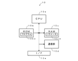
図1は、本発明の第1実施形態に係る二次電池状態検出装置を有する車両の電源系統を示す図である。この図において、二次電池状態検出装置1は、制御部10、電圧センサ11、電流センサ12、温度センサ13、および、放電回路15を主要な構成要素としており、二次電池14の状態を検出する。ここで、制御部10は、電圧センサ11、電流センサ12、および、温度センサ13からの出力を参照し、二次電池14の状態を検出する。電圧センサ11は、二次電池14の端子電圧を検出し、制御部10に通知する。電流センサ12は、二次電池14に流れる電流を検出し、制御部10に通知する。温度センサ13は、二次電池14自体または周囲の環境温度を検出し、制御部10に通知する。放電回路15は、例えば、直列接続された半導体スイッチと抵抗素子等によって構成され、制御部10によって半導体スイッチがオン/オフ制御されることにより二次電池14を間欠的に放電させる。
(A) Description of Configuration of First Embodiment FIG. 1 is a diagram showing a power supply system of a vehicle having a secondary battery state detection device according to the first embodiment of the present invention. In this figure, the secondary battery
二次電池14は、例えば、鉛蓄電池、ニッケルカドミウム電池、ニッケル水素電池、または、リチウムイオン電池等によって構成され、オルタネータ16によって充電され、スタータモータ18を駆動してエンジンを始動するとともに、負荷19に電力を供給する。オルタネータ16は、エンジン17によって駆動され、交流電力を発生して整流回路によって直流電力に変換し、二次電池14を充電する。
The
エンジン17は、例えば、ガソリンエンジンおよびディーゼルエンジン等のレシプロエンジンまたはロータリーエンジン等によって構成され、スタータモータ18によって始動され、トランスミッションを介して駆動輪を駆動し車両に推進力を与えるとともに、オルタネータ16を駆動して電力を発生させる。スタータモータ18は、例えば、直流電動機によって構成され、二次電池14から供給される電力によって回転力を発生し、エンジン17を始動する。負荷19は、例えば、電動ステアリングモータ、デフォッガ、イグニッションコイル、カーオーディオ、および、カーナビゲーション等によって構成され、二次電池14からの電力によって動作する。なお、エンジン17の代わりに電動モータを使用するようにしてもよい。
The engine 17 is composed of, for example, a reciprocating engine such as a gasoline engine and a diesel engine, a rotary engine, or the like. Drive to generate power. The
図2は、図1に示す制御部10の詳細な構成例を示す図である。この図に示すように、制御部10は、CPU(Central Processing Unit)10a、ROM(Read Only Memory)10b、RAM(Random Access Memory)10c、通信部10d、I/F(Interface)10eを有している。ここで、CPU10aは、ROM10bに格納されているプログラム10baに基づいて各部を制御する。ROM10bは、半導体メモリ等によって構成され、プログラム10ba等を格納している。RAM10cは、半導体メモリ等によって構成され、プログラムbaを実行する際に生成されるデータや、後述するテーブルまたは数式等のパラメータ10caを格納する。通信部10dは、上位の装置であるECU(Electronic Control Unit)等との間で通信を行い、検出した情報を上位装置に通知する。I/F10eは、電圧センサ11、電流センサ12、および、温度センサ13から供給される信号をデジタル信号に変換して取り込むとともに、放電回路15に駆動電流を供給してこれを制御する。
FIG. 2 is a diagram illustrating a detailed configuration example of the
(B)第1実施形態の動作原理の説明
つぎに、図を参照して、本発明の第1実施形態の動作原理について説明する。図3は二次電池14を放電させた場合における二次電池14の抵抗値の時間的な変化を示す図である。この図3において、横軸は時間(s)を示し、縦軸は抵抗(Ω)を示す。また、実線の曲線は二次電池の抵抗値の時間的変化を示す。タイミングt0において放電が開始されると、この図3に示すように、二次電池14の抵抗値は時間の経過とともに増加し、所定の時間が経過すると一定となる。ここで、二次電池14の放電中の抵抗は、化学反応に起因する抵抗成分である反応抵抗を有しており、この反応抵抗は二次電池のサイズ(初期満充電容量)との間に高い相関性を有することが、本願発明者の実験によって明らかになった。そこで、本実施形態では、二次電池14の放電時における抵抗値(図3に示すZ)を求め、求めた抵抗値から二次電池14のサイズを推定する。そして、推定されたサイズを参照して、最適な補正係数を選択することで、二次電池14の状態(例えば、SOCまたはSOH)をより精度良く推定することができる。なお、第1実施形態では、「反応抵抗に関する値」とは、二次電池14の放電時における抵抗値を示すものとする。
(B) Description of Operation Principle of First Embodiment Next, the operation principle of the first embodiment of the present invention will be described with reference to the drawings. FIG. 3 is a diagram showing temporal changes in the resistance value of the
つぎに、本発明の実施形態のより詳細な動作について説明する。例えば、二次電池14がユーザ等によって新品に交換された場合には、制御部10のCPU10aは、放電回路15を制御し、二次電池14を所定の周期でパルス放電させ、そのときの電圧、電流、および、温度を電圧センサ11、電流センサ12、および、温度センサ13によって検出し、これらの検出値に基づいて二次電池14のSOCを算出する。
Next, a more detailed operation of the embodiment of the present invention will be described. For example, when the
そして、CPU10aは、算出したSOCを参照し、二次電池14が満充電(SOC=100%)の状態である場合には、以下の処理を実行し、それ以外の場合には、二次電池14が満充電の状態になるまで待機する。なお、満充電の状態まで待機するのは、SOCが同じとなる条件で測定する方が、測定精度が高くなるためである。もちろん、所定のSOC(例えば、90%)を基準として測定を実行するようにしてもよい。
Then, the CPU 10a refers to the calculated SOC, and executes the following process when the
二次電池14が満充電の状態になった場合には、二次電池14が放電状態になるまで待機する。例えば、スタータモータ18が回転されるまで待機し、ユーザがイグニッションをオンの状態にした場合には、スタータモータ18がその後に回転されると判定し、制御部10は、放電前に二次電池14に流れる電流Ibと、二次電池14の電圧Vbを検出する。
When the
図4は、スタータモータ18によるクランキングが実行された場合の二次電池14に流れる電流の時間的な変化を示す図である。この図4では、−0.5(s)付近でイグニッションがオンの状態にされて、微弱な電流(例えば、1A未満の電流)が二次電池14からイグニッションコイル等に供給される。そして、0(s)においてスタータモータ18への電力の供給が開始されると、突入電流が流れ、スタータモータ18が回転を開始し、エンジン17がクランキングされる。スタータモータ18が回転を開始すると、エンジン17の図示しないピストンが上死点に達するタイミングで小さなピーク電流が流れ、エンジン17の回転数が上昇するとともに放電電流の値が減少し、エンジン17が完爆状態になるとスタータモータ18への電力の供給が停止される。本実施形態では、スタータモータ18が回転される直前における二次電池14の電圧および電流を測定し、これらを電圧Vbおよび電流Ibとする。そして、放電開始から所定の時間が経過し、図3に示す抵抗値が一定の値になるタイミング(例えば、t1以降のタイミング)において、再度、二次電池14の電圧および電流を所定のサンプリング周期で測定し、これらをV(tn)およびI(tn)とする。なお、tnはエンジン17への電力の供給開始からの経過時間を示す変数である。
FIG. 4 is a diagram showing temporal changes in the current flowing through the
制御部10は、サンプリングを実行する毎に、以下の式(1)に基づいて、Z(tn)を計算するとともに、count_tnの値を1ずつインクリメントする(count_tn=count_tn+1とする)。ここで、式(1)では、放電前の電圧Vbから放電中の電圧V(tn)を減算して得た値を、放電前の電流Ibから放電中の電流I(tn)を減算して得た値で除算することにより、Z(tn)を得る。なお、count_tnは、後述する式(2)で用いる。
Every time sampling is performed, the

また、制御部10は、以下の式(2)に基づいて、サンプリング毎に前述した式(1)によって得られるZ(tn)の平均値であるZ(tn_ave)を求める。
Moreover, the
そして、制御部10は、以下の式(3)に基づいて初期満充電容量SOH0を求める。なお、f(Z(tn_ave))は所定の関数を示し、例えば、f(Z(tn_ave))=Z(tn_ave)とすることができる。また、α,βはパラメータであり、予め実測によって求めることができる。
And the
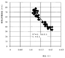
図5は、83個の新品の二次電池14の抵抗値(Z(tn_ave))と、初期満充電容量SOH0との関係を示す図である。この図5に示すように、放電中の抵抗値が小さいほど、初期満充電容量SOH0が大きくなる傾向にあり、抵抗値の初期満充電容量SOH0に対する寄与率R2は、0.8953であり、これらの間には強い相関があることがわかる。
FIG. 5 is a diagram showing the relationship between the resistance values (Z (tn_ave)) of 83 new
図6は、前述した方法によって推定した初期満充電容量SOH0と、実測した初期満充電容量SOH0との関係を示す図である。この図6に示すように、推定した初期満充電容量SOH0と、実測した初期満充電容量SOH0とは、破線で示す傾きが“1”の直線上の上またはその近傍に配置され、推測が正確であることか示されている。また、推定した初期満充電容量SOH0と、実測した初期満充電容量SOH0との間の寄与率R2は、0.91であり、これらの間には強い相関があることがわかる。 FIG. 6 is a diagram showing the relationship between the initial full charge capacity SOH0 estimated by the above-described method and the actually measured initial full charge capacity SOH0. As shown in FIG. 6, the estimated initial full charge capacity SOH0 and the actually measured initial full charge capacity SOH0 are arranged on or near the straight line with the slope indicated by the broken line “1”, and the estimation is accurate. It is shown that it is. Further, an estimated initial full charge capacity SOH0, contribution R 2 between the actually measured initial full charge capacity SOH0 is 0.91, it can be seen that between them there is a strong correlation.
以上に説明したように、本発明の第1実施形態によれば、二次電池14の放電前後の電圧値および電流値から抵抗値を求め、この抵抗値から二次電池14の初期満充電容量を求めるようにしたので、抵抗値と初期満充電容量との高い相関に基づいて、二次電池14の初期満充電容量を精度良く求めることができる。また、このようにして求めた初期満充電容量を参照して、各種の補正係数を選択することにより、二次電池14の状態をより精度良く検出することが可能になる。
As described above, according to the first embodiment of the present invention, the resistance value is obtained from the voltage value and the current value before and after the discharge of the
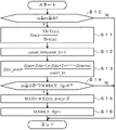
つぎに、図7を参照して、制御部10において実行される詳細な処理の一例について説明する。図7は制御部10において実行される処理の一例を説明するフローチャートである。なお、この処理は、車両に新たな二次電池14が搭載されるとともに、二次電池14が満充電(SOC=100%)になった場合であって、スタータモータ18が回転されたときに一定間隔(例えば、数ms〜数百ms間隔)で繰り返し実行される。図7に示すフローチャートが開始されると以下のステップが実行される。
Next, an example of detailed processing executed in the
ステップS10では、CPU10aは、スタータモータ18への電力の供給開始からの経過時間tnが所定の範囲内(ta≦tn≦tb)に入ったか否かを判定し、所定の範囲内に入ったと判定した場合(ステップS10:Yes)にはステップS11に進み、それ以外の場合(ステップS10:No)には処理を終了する。図4の例では、例えば、0.4[s]から0.6[s]の間を所定の範囲内(ta≦tn≦tb)として用いることができる。なお、このように、スタータモータ18が回転を開始してから一定時間経過後の電圧および電流を測定するのは、図3に示すように、抵抗値が一定になる範囲を測定するためである。
In step S10, the CPU 10a determines whether or not the elapsed time tn from the start of power supply to the
ステップS11では、CPU10aは、前述した式(1)に基づいてZ(tn)を計算する。なお、VbおよびIbは、二次電池14が放電を開始する前の電圧および電流である。より詳細には、例えば、図4に示す−0.4[s]から0[s]の間の電圧および電流を用いることができる。
In step S11, the CPU 10a calculates Z (tn) based on the above-described equation (1). Vb and Ib are the voltage and current before the
ステップS12では、CPU10aは、変数count_tnの値を“1”だけインクリメントする。この結果、変数count_tnの値は、処理の回数に応じて1ずつインクリメントされることになる。 In step S12, the CPU 10a increments the value of the variable count_tn by “1”. As a result, the value of the variable count_tn is incremented by 1 according to the number of processes.
ステップS13では、CPU10aは、前述した式(2)に基づいて、Z(tn_ave)を算出する。より詳細には、Z(tn)は、1回目の測定によって得られた抵抗値であり、Z(tn+m)は、(m+1)回目の測定によって得られた抵抗値である。したがって、式(2)により、第1回目から第(m+1)回目の測定によって得られた抵抗の平均値が算出される。 In step S13, the CPU 10a calculates Z (tn_ave) based on the above-described equation (2). More specifically, Z (tn) is a resistance value obtained by the first measurement, and Z (tn + m) is a resistance value obtained by the (m + 1) th measurement. Therefore, the average value of the resistances obtained by the first to (m + 1) th measurements is calculated by the equation (2).
ステップS14では、CPU10aは、tn≧tbであり、かつ、SOH0CE_flg=0を満たすか否かを判定し、これらを共に満たす場合(ステップS14:Yes)にはステップS15に進み、それ以外の場合(ステップS14:No)には処理を終了する。なお、SOH0CE_flgは、初期値が“0”であり、ステップS15に示す計算を実行した場合にその値が“1”に変更されるフラグである。このため、ta≦tn<tbの範囲では、tn≧tbの条件を満たさないので、Noと判定されて処理を終了し、tn=tbになった場合には、Yesと判定されてステップS15に進み、SOH0CEが計算され、ステップS16でSOH0CE_flagが“1”にされるので、それ以降(tn>tb)の処理におけるステップS14ではNoと判定されて処理を終了する。すなわち、tn=tbになった場合に1回だけステップS15およびステップS16の処理が実行される。 In step S14, the CPU 10a determines whether or not tn ≧ tb and SOH0CE_flg = 0 is satisfied. If both are satisfied (step S14: Yes), the process proceeds to step S15, and otherwise ( In step S14: No), the process ends. SOH0CE_flg is a flag whose initial value is “0” and whose value is changed to “1” when the calculation shown in step S15 is executed. For this reason, in the range of ta ≦ tn <tb, the condition of tn ≧ tb is not satisfied. Therefore, it is determined No and the process is terminated. If tn = tb, the determination is Yes and the process proceeds to step S15. Then, SOH0CE is calculated, and SOH0CE_flag is set to “1” in step S16, so that it is determined No in step S14 in the subsequent processing (tn> tb), and the processing ends. That is, when tn = tb, the processes of step S15 and step S16 are executed only once.
ステップS15では、CPU10aは、前述した式(3)に基づいて、初期満充電容量SOH0を計算する。なお、αおよびβとしては、実測等によって予め求めた値をROM10bに格納しておき、この値を読み出して用いることができる。 In step S15, the CPU 10a calculates an initial full charge capacity SOH0 based on the above-described equation (3). As α and β, values obtained in advance by actual measurement or the like are stored in the ROM 10b, and these values can be read and used.
ステップS16では、CPU10aは、SOH0CE_flgを“1”に設定し、処理を終了する。 In step S16, the CPU 10a sets SOH0CE_flg to “1” and ends the process.
以上の処理によれば、スタータモータ18によってエンジン17が始動される際には、スタータモータ18に電力が供給開始される直前に二次電池14の電圧Vbおよび電流Ibが測定され、スタータモータ18への電力供給が開始された場合には、一定時間が経過した後に電圧V(tn)および電流I(tn)が計測され、式(1)に基づいてZ(tn)が計算される。このようにして求めたZ(tn)から平均値Z(tn_ave)が求められ、このZ(tn_ave)を式(3)に代入することで、初期満充電容量SOH0を得ることができる。
According to the above processing, when the engine 17 is started by the
このようにして求めたSOH0を用いることで、例えば、分極電圧または分極量および成層化電圧または成層化量に応じた正確な補正を行うことができるため、二次電池14の状態をより正確に推定することが可能になる。例えば、SOH0が40Ahである場合には、40Ahに対応する補正係数を選択し、この補正係数に基づいて分極電圧または分極量および成層化電圧または成層化量を補正することができる。
By using SOH0 obtained in this way, for example, accurate correction according to the polarization voltage or polarization amount and the stratification voltage or stratification amount can be performed, so that the state of the
(C)第2実施形態の構成の説明
つぎに、本発明の第2実施形態について説明する。なお、本発明の第2実施形態の構成は図1および図2と同じであるが、制御部10において実行される処理が第1実施形態とは異なっている。そこで、第2実施形態の構成についての説明は省略し、第2実施形態の動作について説明する。
(C) Description of Configuration of Second Embodiment Next, a second embodiment of the present invention will be described. The configuration of the second embodiment of the present invention is the same as that of FIGS. 1 and 2, but the processing executed in the
(D)第2実施形態の動作の説明
つぎに、本発明の第2実施形態の動作について説明する。図8は、第2実施形態の動作原理を説明するための図である。第1実施形態では、図3に示すように二次電池14の放電中の抵抗値に基づいて初期満充電容量を求めるようにした。しかしながら、図8に示すように、二次電池14の放電中の抵抗成分としては、反応抵抗Zctと導体抵抗Zcnが存在する。ここで、導体抵抗Zcnは、例えば、電極の形状や大きさ等によって異なる値を有する。より詳細には、同じサイズの二次電池でもアイドリング時にエンジンを停止して燃費向上を図るための技術である「アイドリングストップ」に用いるための二次電池は、通常の二次電池に比較して導体抵抗が小さくなるように設計される。一方、反応抵抗Zctは、化学反応による電荷の移動に応じた抵抗であり、二次電池のサイズ(初期満充電容量)との間に高い相関性を有する抵抗成分である。そこで、第2実施形態では、求めた抵抗成分から導体抵抗Zcnを除算することで、反応抵抗Zct成分を抽出し、この成分に基づいて二次電池14の初期満充電容量を推定する。なお、第2実施形態では、「反応抵抗に関する値」とは、二次電池14の放電時における反応抵抗Zctの値を示すものとする。
(D) Description of Operation of Second Embodiment Next, the operation of the second embodiment of the present invention will be described. FIG. 8 is a diagram for explaining the operation principle of the second embodiment. In the first embodiment, as shown in FIG. 3, the initial full charge capacity is obtained based on the resistance value during discharge of the
つぎに、図9を参照して、第2実施形態の詳細な動作について説明する。図9は、第2実施形態において実行される処理の一例を説明するためのフローチャートである。図9に示すフローチャートは、スタータモータ18の回転が開始された場合に一定間隔(例えば、数ms〜数百ms間隔)で繰り返し実行される。このフローチャートが開始されると、以下のステップが実行される。
Next, the detailed operation of the second embodiment will be described with reference to FIG. FIG. 9 is a flowchart for explaining an example of processing executed in the second embodiment. The flowchart shown in FIG. 9 is repeatedly executed at regular intervals (for example, intervals of several ms to several hundred ms) when the rotation of the
ステップS30では、CPU10aは、スタータモータ18への電力の供給開始からの経過時間を示す変数tnの値が、tn=t0であるか否かを判定し、tn=t0である場合(ステップS30:Yes)にはステップS31に進み、それ以外の場合(ステップS30:No)にはステップS32に進む。例えば、ステップS30の処理が実行された時点がスタータモータ18への電力供給を開始したタイミング(図8に示すt0または図4に示す時間“0”)である場合にはYesと判定されてステップS31に進み、それ以外の場合にはNoと判定されてステップS32に進む。
In step S30, the CPU 10a determines whether or not the value of the variable tn indicating the elapsed time from the start of power supply to the
ステップS31では、CPU10aは、以下の式(4)に基づいてZ(t0)を算出する。なお、Z(t0)は、t0における二次電池14の抵抗を示す。
In step S31, the CPU 10a calculates Z (t0) based on the following equation (4). Z (t0) represents the resistance of the
ステップS32では、CPU10aは、スタータモータ18への電力の供給を開始してからの経過時間tnが所定の範囲内(ta≦tn≦tb)に入ったか否かを判定し、所定の範囲内に入ったと判定した場合(ステップS32:Yes)にはステップS33に進み、それ以外の場合(ステップS32:No)にはステップS38に進む。図4の例では、例えば、0.4[s]から0.6[s]の範囲を用いることができる。なお、このように、スタータモータ18が回転を開始してから一定時間経過後の電圧および電流を測定するのは、前述のように二次電池14の抵抗値が一定になる範囲を測定するためである。
In step S32, the CPU 10a determines whether or not the elapsed time tn from the start of power supply to the
ステップS33では、CPU10aは、前述した式(1)に基づいてZ(tn)を計算する。なお、VbおよびIbは、二次電池14が放電を開始する前の電圧および電流である。より詳細には、図4に示す−0.4[s]から0[s]の範囲(イグニッションコイルに1A前後の電流が流れている範囲)の電圧および電流を用いることができる。
In step S33, the CPU 10a calculates Z (tn) based on the above-described equation (1). Vb and Ib are the voltage and current before the
ステップS34では、CPU10aは、処理の回数をカウントする変数count_tnの値を“1”だけインクリメントする。この結果、変数count_tnの値は、処理の回数に応じて1ずつインクリメントされることになる。 In step S34, the CPU 10a increments the value of the variable count_tn for counting the number of processes by “1”. As a result, the value of the variable count_tn is incremented by 1 according to the number of processes.
ステップS35では、CPU10aは、ステップS33で求めたZ(tn)からステップS31で求めたZ(t0)を減算し、得られた値をZct(tn)とする。ここで、Z(t0)は、図8に示すt0における抵抗値であるので、Zcnに対応する値である。また、Z(tn)は図8に示すZct+Zcnに対応する値である。このため、Zct(tn)−Z(t0)により、図8に示す反応抵抗Zctに対応する値を得ることができる。 In step S35, the CPU 10a subtracts Z (t0) obtained in step S31 from Z (tn) obtained in step S33, and sets the obtained value as Zct (tn). Here, Z (t0) is a resistance value at t0 shown in FIG. 8, and is a value corresponding to Zcn. Z (tn) is a value corresponding to Zct + Zcn shown in FIG. Therefore, a value corresponding to the reaction resistance Zct shown in FIG. 8 can be obtained by Zct (tn) −Z (t0).
ステップS36では、CPU10aは、前述した式(2)に基づいて、Z(tn_ave)を算出する。前述したように、Z(tn)は、第1回目の測定によって得られた抵抗の値であり、Z(tn+m)は、第(m+1)回目の測定によって得られた抵抗の値である。したがって、式(2)では、第1回目から第(m+1)回目の測定によって得られた抵抗の平均値が算出される。 In step S36, the CPU 10a calculates Z (tn_ave) based on the above-described equation (2). As described above, Z (tn) is a resistance value obtained by the first measurement, and Z (tn + m) is a resistance value obtained by the (m + 1) th measurement. Therefore, in Equation (2), the average value of the resistances obtained by the first to (m + 1) th measurements is calculated.
ステップS37では、CPU10aは、以下の式(5)に基づいて、Zct(tn_ave)を算出する。ここで、Zct(tn)は、第1回目の測定によって得られた反応抵抗の値であり、Zct(tn+m)は、第(m+1)回目の測定によって得られた反応抵抗の値である。したがって、式(5)では、第1回目から第(m+1)回目の測定によって得られた反応抵抗の平均値が算出される。 In step S37, the CPU 10a calculates Zct (tn_ave) based on the following equation (5). Here, Zct (tn) is a value of reaction resistance obtained by the first measurement, and Zct (tn + m) is a value of reaction resistance obtained by the (m + 1) th measurement. Therefore, in the equation (5), the average value of the reaction resistance obtained by the first to (m + 1) th measurements is calculated.
ステップS38では、CPU10aは、tn≧tbであり、かつ、SOH0CE_flg=0を満たすか否かを判定し、これらを共に満たす場合(ステップS38:Yes)にはステップS39に進み、それ以外の場合(ステップS38:No)には、処理を終了する。なお、SOH0CE_flgは、初期値が“0”であり、ステップS39に示す計算を実行した後にその値が“1”にされるフラグである。このため、ta≦tn<tbの範囲では、tn≧tbの条件を満たさないので、Noと判定されて処理を終了し、tn=tbになった場合には、Yesと判定されてステップS39に進み、SOH0が算出され、ステップS40でSOH0CE_flagが“1”にされるので、それ以降(tn>tb)の処理ではステップS38ではNoと判定されて処理を終了する。すなわち、tn=tbになった場合に1回だけステップS39およびステップS40の処理が実行される。 In step S38, the CPU 10a determines whether or not tn ≧ tb and SOH0CE_flg = 0 is satisfied, and if both are satisfied (step S38: Yes), the process proceeds to step S39, and otherwise ( In step S38: No), the process ends. SOH0CE_flg is a flag whose initial value is “0” and whose value is set to “1” after the calculation shown in step S39. For this reason, in the range of ta ≦ tn <tb, the condition of tn ≧ tb is not satisfied. Therefore, the determination is No and the process is terminated. If tn = tb, the determination is Yes and the process proceeds to step S39. Then, SOH0 is calculated, and SOH0CE_flag is set to “1” in step S40. Therefore, in the subsequent processing (tn> tb), it is determined No in step S38 and the processing is terminated. That is, when tn = tb, the processes of step S39 and step S40 are executed only once.
ステップS39では、CPU10aは、以下の式(6)に基づいて、初期満充電容量SOH0を計算する。なお、α,β,γとしては、実測によって予め求めた値をROM10bに格納しておき、この値を読み出して用いることができる。 In step S39, the CPU 10a calculates an initial full charge capacity SOH0 based on the following equation (6). As α, β, and γ, values obtained in advance by actual measurement are stored in the ROM 10b, and these values can be read and used.
ステップS40では、CPU10aは、SOH0CE_flgを“1”に設定し、処理を終了する。 In step S40, the CPU 10a sets SOH0CE_flg to “1” and ends the process.
図10は、図9の処理によって測定した83個の新品の二次電池のZct(tn_ave)の値と、初期満充電容量SOH0との関係を示す図である。この図10に示すように、Zct(tn_ave)の値が小さいほど、初期満充電容量SOH0が大きくなる傾向にあり、Zct(tn_ave)の初期満充電容量SOH0に対する寄与率R2は、0.8445であり、これらの間には強い相関があることがわかる。 FIG. 10 is a diagram showing the relationship between the value of Zct (tn_ave) of 83 new secondary batteries measured by the process of FIG. 9 and the initial full charge capacity SOH0. As shown in FIG. 10, the smaller the value of Zct (tn_ave), in the initial full charge capacity SOH0 increases tendency contribution R 2 with respect to the initial full charge capacity SOH0 of Zct (tn_ave) is 0.8445 It can be seen that there is a strong correlation between them.
以上の処理によれば、エンジン17を始動する際の電圧および電流の変化に基づいて、二次電池14の初期満充電容量を正確に推定することができる。このようにして求めたSOH0を用いることで、例えば、分極電圧または分極量および成層化電圧または成層化量に応じた正確な補正を行うことができるため、二次電池14の状態をより正確に推定することが可能になる。
According to the above processing, it is possible to accurately estimate the initial full charge capacity of the
(D)変形実施形態の説明
以上の実施形態は一例であって、本発明が上述したような場合のみに限定されるものでないことはいうまでもない。例えば、以上の各実施形態では、初期満充電容量SOH0を算出することを目的としたが、例えば、図11に示すように、算出した初期満充電容量SOH0に基づいて、二次電池14の大きさを判定するようにしてもよい。この図11では、図7と比較すると、ステップS50〜S54の処理が追加されている。それ以外は、図7と同様であるので、以下では、ステップS50〜S54について説明する。ステップS15の処理によりSOH0が計算され、ステップS16の処理によりSOH0CE_flgが“1”にされた後、ステップS50に進む。ステップS50では、ステップS15で算出したSOH0がSOH_small≦SOH0≦SOH_largeの条件を満たすか否かを判定し、満たす場合(ステップS50:Yes)にはステップS51に進み、Battery_size=middleと判定して処理を終了し、それ以外の場合(ステップS50:No)にはステップS52に進む。ステップS52では、SOH0<SOH_smallを満たすか否かを判定し、満たす場合(ステップS52:Yes)にはステップS53に進み、Battery_size=smallと判定して処理を終了し、それ以外の場合(ステップS52:No)にはステップS54に進み、Battery_size=lageと判定して処理を終了する。以上の処理によれば、判別閾値であるSOH_small,SOH_middle,SOH_largeを適宜設定することにより、推定された初期満充電容量SOH0に基づいて、二次電池14のサイズをsmall,middle,largeに分類することができる。なお、図11では、3つのサイズに分類するようにしたが、2つまたは4つ以上に分類するようにしてもよい。
(D) Description of Modified Embodiment The above embodiment is an example, and it is needless to say that the present invention is not limited to the case described above. For example, in each of the above embodiments, the purpose is to calculate the initial full charge capacity SOH0. However, as shown in FIG. 11, for example, the size of the
また、以上の各実施形態では、スタータモータ18を回転させる前の電圧Vbおよび電流Ibについては、1回だけ測定するようにしたが、例えば、複数回測定してその平均値を用いるようにしてもよい。また、スタータモータ18が回転中においては、電圧V(tn)および電流I(tn)を複数回測定し、複数回の測定結果に基づいて平均値であるZ(tn_ave)またはZct(tn_ave)を計算するようにしたが、例えば、1回の測定結果を用いてこれらを計算するようにしてもよい。すなわち、電圧Vbおよび電流Ibならびに電圧V(tn)および電流I(tn)については、それぞれ1回または複数回のいずれを選択するようにしてもよい。
Further, in each of the above embodiments, the voltage Vb and the current Ib before rotating the
また、以上の各実施形態では、ta〜tbの期間中に測定した電圧および電流は全て使用するようにした。しかしながら、実測結果によれば、図4に示す電流変化の変曲点(エンジン17のピストンが上死点または下死点に達する点)の電圧および電流を用いない方が、推定精度が高いことが判明したので、変曲点近傍の電圧および電流については測定対象または計算対象から除外するようにしてもよい。具体的には、サンプリングによって得られた電流を時間的に微分し、得られた値が“0”に近い場合には、変曲点であるとし、変曲点前後のデータについては計算対象から除外することができる。 In each of the above embodiments, all the voltages and currents measured during the period from ta to tb are used. However, according to the actual measurement results, the accuracy of estimation is higher when the voltage and current at the inflection point (the point at which the piston of the engine 17 reaches the top dead center or the bottom dead center) shown in FIG. 4 are not used. Therefore, the voltage and current near the inflection point may be excluded from the measurement target or calculation target. Specifically, the current obtained by sampling is differentiated with respect to time, and when the obtained value is close to “0”, it is determined as an inflection point. Can be excluded.
また、以上の各実施形態では、スタータモータ18に電流が流れる場合を測定対象として説明したが、二次電池14にある程度の大きさの電流が所定時間流れる場合であれば、測定対象とすることができる。例えば、停車時においてステアリングが操作される場合(いわゆる「据え切り」をした場合)にはステアリングモータにある程度の大きさの電流(例えば、百アンペア程度)が一定時間以上流れるので、その場合も測定対象とすることができる。
Further, in each of the above embodiments, the case where a current flows through the
また、以上の各実施形態では、SOH0を求める式としては、式(3)および式(6)を用いるようにしたが、これらは一例であって、これら以外の式を用いることができる。例えば、前述の説明では、f(Z(tn))およびf(Zct(tn))については、f(Z(tn))=Z(tn)およびf(Zct(tn))=Zct(tn)として説明したが、例えば、2次以上の高次式もしくは指数関数、または、多項式を用いるようにしてもよい。 Further, in each of the above embodiments, the equations (3) and (6) are used as the equations for obtaining SOH0. However, these are merely examples, and equations other than these can be used. For example, in the above description, for f (Z (tn)) and f (Zct (tn)), f (Z (tn)) = Z (tn) and f (Zct (tn)) = Zct (tn) However, for example, a higher-order expression or an exponential function having a second or higher order, or a polynomial may be used.
また、図11に示す実施形態では、二次電池14の大きさを、大、中、小の3つに分類するようにしたが、例えば、2つに分類したり、4つ以上に分類したりするようにしてもよい。また、サイズを分類するのではなく、初期満充電容量の単位であるAhを推定して表示するようにしてもよい。
In the embodiment shown in FIG. 11, the size of the
また、以上の各実施形態では、満充電状態になった後に、二次電池14の測定を実行するようにしたが、例えば、満充電状態でない場合に実行するようにしてもよい。なお、その場合には、二次電池14のSOC毎に式(3)および式(6)のパラメータα,β,γをSOCに応じて準備しておき、SOCの値に応じたパラメータを読み出してSOH0を算出するようにしてもよい。
Further, in each of the embodiments described above, the measurement of the
1 二次電池状態検出装置
10 制御部(求出手段、推定手段)
10a CPU
10b ROM
10c RAM
10d 表示部
10e I/F
11 電圧センサ(検出手段)
12 電流センサ(検出手段)
13 温度センサ
14 二次電池
15 放電回路
16 オルタネータ
17 エンジン
18 スタータモータ
19 負荷
DESCRIPTION OF
10a CPU
10b ROM
10c RAM
10d Display unit 10e I / F
11 Voltage sensor (detection means)
12 Current sensor (detection means)
13
Claims (6)
前記二次電池に流れる電流の値および前記二次電池の電圧の値を検出する検出手段と、
前記二次電池の放電前の電圧値および電流値を前記検出手段によって検出するとともに、前記二次電池の放電中の電圧値および電流値を前記検出手段によって検出し、これらの電圧値および電流値に基づいて、前記二次電池の反応抵抗に関する値を求出する求出手段と、
前記求出手段によって求出された前記反応抵抗に関する値と、前記二次電池の初期満充電容量とが有する相関関係に基づいて、前記初期満充電容量を推定する推定手段と、
を有することを特徴とする二次電池状態検出装置。 In a secondary battery state detection device that detects the state of a secondary battery mounted on a vehicle,
Detecting means for detecting a value of a current flowing through the secondary battery and a voltage value of the secondary battery;
The voltage value and current value before discharge of the secondary battery are detected by the detection means, and the voltage value and current value during discharge of the secondary battery are detected by the detection means, and these voltage value and current value are detected. And obtaining means for obtaining a value related to the reaction resistance of the secondary battery,
Estimating means for estimating the initial full charge capacity based on a correlation between the value relating to the reaction resistance obtained by the obtaining means and the initial full charge capacity of the secondary battery;
A secondary battery state detection device comprising:
前記二次電池に流れる電流の値および前記二次電池の電圧の値を検出する検出ステップと、
前記二次電池の放電前の電圧値および電流値を前記検出ステップにおいて検出するとともに、前記二次電池の放電中の電圧値および電流値を前記検出ステップにおいて検出し、これらの電圧値および電流値に基づいて、前記二次電池の反応抵抗に関する値を求出する求出ステップと、
前記求出ステップにおいて求出された前記反応抵抗に関する値と、前記二次電池の初期満充電容量とが有する相関関係に基づいて、前記初期満充電容量を推定する推定ステップと、
を有することを特徴とする二次電池状態検出方法。 In a secondary battery state detection method for detecting a state of a secondary battery mounted on a vehicle,
A detection step of detecting a value of a current flowing through the secondary battery and a voltage value of the secondary battery;
The voltage value and current value before discharging of the secondary battery are detected in the detecting step, and the voltage value and current value during discharging of the secondary battery are detected in the detecting step, and these voltage value and current value are detected. And obtaining a value relating to a reaction resistance of the secondary battery based on
An estimation step of estimating the initial full charge capacity based on a correlation between a value related to the reaction resistance obtained in the obtaining step and an initial full charge capacity of the secondary battery;
A secondary battery state detection method comprising:
Priority Applications (1)
| Application Number | Priority Date | Filing Date | Title |
|---|---|---|---|
| JP2014042207A JP6210552B2 (en) | 2014-03-04 | 2014-03-04 | Secondary battery state detection device and secondary battery state detection method |
Applications Claiming Priority (1)
| Application Number | Priority Date | Filing Date | Title |
|---|---|---|---|
| JP2014042207A JP6210552B2 (en) | 2014-03-04 | 2014-03-04 | Secondary battery state detection device and secondary battery state detection method |
Publications (2)
| Publication Number | Publication Date |
|---|---|
| JP2015169450A JP2015169450A (en) | 2015-09-28 |
| JP6210552B2 true JP6210552B2 (en) | 2017-10-11 |
Family
ID=54202325
Family Applications (1)
| Application Number | Title | Priority Date | Filing Date |
|---|---|---|---|
| JP2014042207A Active JP6210552B2 (en) | 2014-03-04 | 2014-03-04 | Secondary battery state detection device and secondary battery state detection method |
Country Status (1)
| Country | Link |
|---|---|
| JP (1) | JP6210552B2 (en) |
Cited By (1)
| Publication number | Priority date | Publication date | Assignee | Title |
|---|---|---|---|---|
| CN109794439A (en) * | 2017-11-16 | 2019-05-24 | 河北银隆新能源有限公司 | A kind of lithium battery performance screening technique |
Families Citing this family (4)
| Publication number | Priority date | Publication date | Assignee | Title |
|---|---|---|---|---|
| CN105529784B (en) * | 2016-02-04 | 2018-02-27 | 蒙城信和汽车有限公司 | Energy-saving charging station |
| CN106684475B (en) * | 2017-01-16 | 2019-03-26 | 哈尔滨理工大学 | A kind of method for separating of ferric phosphate lithium cell |
| JP6979896B2 (en) * | 2018-02-06 | 2021-12-15 | 古河電気工業株式会社 | Rechargeable battery status detector and rechargeable battery status detection method |
| JP7072414B2 (en) * | 2018-03-20 | 2022-05-20 | 古河電気工業株式会社 | Rechargeable battery status detector and rechargeable battery status detection method |
Family Cites Families (6)
| Publication number | Priority date | Publication date | Assignee | Title |
|---|---|---|---|---|
| JPH0862309A (en) * | 1994-08-24 | 1996-03-08 | N T T Facilities:Kk | Storage battery measuring device |
| JP3930777B2 (en) * | 2001-08-03 | 2007-06-13 | 矢崎総業株式会社 | Battery degradation degree calculation method and apparatus |
| JP4090713B2 (en) * | 2001-08-23 | 2008-05-28 | 日本電信電話株式会社 | Nickel metal hydride battery capacity estimation method |
| JP5070790B2 (en) * | 2006-10-02 | 2012-11-14 | 新神戸電機株式会社 | Battery state detection system and automobile equipped with the same |
| JP2012032267A (en) * | 2010-07-30 | 2012-02-16 | Renesas Electronics Corp | Remaining capacitance detection apparatus and battery control ic |
| JP5653881B2 (en) * | 2011-10-14 | 2015-01-14 | 古河電気工業株式会社 | Secondary battery state detection device and secondary battery state detection method |
-
2014
- 2014-03-04 JP JP2014042207A patent/JP6210552B2/en active Active
Cited By (1)
| Publication number | Priority date | Publication date | Assignee | Title |
|---|---|---|---|---|
| CN109794439A (en) * | 2017-11-16 | 2019-05-24 | 河北银隆新能源有限公司 | A kind of lithium battery performance screening technique |
Also Published As
| Publication number | Publication date |
|---|---|
| JP2015169450A (en) | 2015-09-28 |
Similar Documents
| Publication | Publication Date | Title |
|---|---|---|
| JP6479650B2 (en) | Secondary battery state detection device and secondary battery state detection method | |
| JP5051661B2 (en) | Method and apparatus for estimating SOC value of secondary battery, and degradation determination method and apparatus | |
| JP6490414B2 (en) | Secondary battery state detection device and secondary battery state detection method | |
| US10295605B2 (en) | State detecting method and state detecting device of secondary battery | |
| CN108885242B (en) | Secondary battery degradation estimation device and secondary battery degradation estimation method | |
| JP6210552B2 (en) | Secondary battery state detection device and secondary battery state detection method | |
| JP6440377B2 (en) | Secondary battery state detection device and secondary battery state detection method | |
| JP5598869B2 (en) | Secondary battery state detection device and secondary battery state detection method | |
| JP5684172B2 (en) | Secondary battery state detection device and secondary battery state detection method | |
| US10393814B2 (en) | Secondary battery state detection device and secondary battery state detection method | |
| EP3343689A1 (en) | Deterioration degree estimation device and deterioration degree estimation method | |
| JP6575308B2 (en) | Internal resistance calculation device, computer program, and internal resistance calculation method | |
| JP5653881B2 (en) | Secondary battery state detection device and secondary battery state detection method | |
| JP2008089447A (en) | Device for estimating internal resistance of battery | |
| CN111108403A (en) | Short-circuit prediction device and short-circuit prediction method for rechargeable battery | |
| JP6498920B2 (en) | Secondary battery state detection device and secondary battery state detection method | |
| JP6452403B2 (en) | Secondary battery state detection device and secondary battery state detection method | |
| JP2012189373A (en) | Secondary battery condition detection device and secondary battery condition detection method | |
| JP2013108919A (en) | Soc estimator | |
| JP2022044621A (en) | Rechargeable battery liquid decrease detection device and rechargeable battery liquid decrease detection method | |
| JP5554310B2 (en) | Internal resistance measuring device and internal resistance measuring method | |
| JP6979896B2 (en) | Rechargeable battery status detector and rechargeable battery status detection method | |
| JP6631172B2 (en) | Internal resistance calculation device, computer program, and internal resistance calculation method | |
| JP6953323B2 (en) | Rechargeable battery status detector and rechargeable battery status detection method | |
| JP2004301784A (en) | Dischargeable capacity estimating method and device for battery |
Legal Events
| Date | Code | Title | Description |
|---|---|---|---|
| A621 | Written request for application examination |
Free format text: JAPANESE INTERMEDIATE CODE: A621 Effective date: 20161214 |
|
| TRDD | Decision of grant or rejection written | ||
| A977 | Report on retrieval |
Free format text: JAPANESE INTERMEDIATE CODE: A971007 Effective date: 20170816 |
|
| A01 | Written decision to grant a patent or to grant a registration (utility model) |
Free format text: JAPANESE INTERMEDIATE CODE: A01 Effective date: 20170823 |
|
| A61 | First payment of annual fees (during grant procedure) |
Free format text: JAPANESE INTERMEDIATE CODE: A61 Effective date: 20170907 |
|
| R151 | Written notification of patent or utility model registration |
Ref document number: 6210552 Country of ref document: JP Free format text: JAPANESE INTERMEDIATE CODE: R151 |
|
| S531 | Written request for registration of change of domicile |
Free format text: JAPANESE INTERMEDIATE CODE: R313531 |
|
| R350 | Written notification of registration of transfer |
Free format text: JAPANESE INTERMEDIATE CODE: R350 |