JP6490675B2 - Smart home hazard detector that gives a non-alarm status signal at the right moment - Google Patents
Smart home hazard detector that gives a non-alarm status signal at the right moment Download PDFInfo
- Publication number
- JP6490675B2 JP6490675B2 JP2016520665A JP2016520665A JP6490675B2 JP 6490675 B2 JP6490675 B2 JP 6490675B2 JP 2016520665 A JP2016520665 A JP 2016520665A JP 2016520665 A JP2016520665 A JP 2016520665A JP 6490675 B2 JP6490675 B2 JP 6490675B2
- Authority
- JP
- Japan
- Prior art keywords
- hazard detector
- light
- light emission
- status
- hazard
- Prior art date
- Legal status (The legal status is an assumption and is not a legal conclusion. Google has not performed a legal analysis and makes no representation as to the accuracy of the status listed.)
- Active
Links
- 238000012545 processing Methods 0.000 claims description 140
- 238000000034 method Methods 0.000 claims description 117
- 238000001514 detection method Methods 0.000 claims description 71
- 230000004044 response Effects 0.000 claims description 58
- 230000033001 locomotion Effects 0.000 claims description 55
- 230000006854 communication Effects 0.000 claims description 49
- 238000004891 communication Methods 0.000 claims description 49
- 239000000779 smoke Substances 0.000 claims description 40
- UGFAIRIUMAVXCW-UHFFFAOYSA-N Carbon monoxide Chemical compound [O+]#[C-] UGFAIRIUMAVXCW-UHFFFAOYSA-N 0.000 claims description 30
- 229910002091 carbon monoxide Inorganic materials 0.000 claims description 30
- 230000003287 optical effect Effects 0.000 claims description 15
- 238000004590 computer program Methods 0.000 claims description 14
- 238000005286 illumination Methods 0.000 claims description 13
- 230000009471 action Effects 0.000 claims description 11
- 230000006870 function Effects 0.000 description 44
- 230000000007 visual effect Effects 0.000 description 42
- 230000000694 effects Effects 0.000 description 28
- 238000012360 testing method Methods 0.000 description 25
- 238000003860 storage Methods 0.000 description 23
- 239000003086 colorant Substances 0.000 description 20
- 238000012544 monitoring process Methods 0.000 description 15
- 238000010586 diagram Methods 0.000 description 14
- 238000004458 analytical method Methods 0.000 description 11
- 230000007613 environmental effect Effects 0.000 description 10
- 230000000875 corresponding effect Effects 0.000 description 9
- 239000003570 air Substances 0.000 description 8
- 230000015654 memory Effects 0.000 description 8
- 230000036541 health Effects 0.000 description 6
- 230000002262 irrigation Effects 0.000 description 6
- 238000003973 irrigation Methods 0.000 description 6
- 230000008569 process Effects 0.000 description 6
- 238000003032 molecular docking Methods 0.000 description 5
- 239000000126 substance Substances 0.000 description 5
- 230000001960 triggered effect Effects 0.000 description 5
- CURLTUGMZLYLDI-UHFFFAOYSA-N Carbon dioxide Chemical compound O=C=O CURLTUGMZLYLDI-UHFFFAOYSA-N 0.000 description 4
- 230000008901 benefit Effects 0.000 description 4
- 238000004140 cleaning Methods 0.000 description 4
- 230000007423 decrease Effects 0.000 description 4
- 125000001475 halogen functional group Chemical group 0.000 description 4
- 230000008859 change Effects 0.000 description 3
- 230000007246 mechanism Effects 0.000 description 3
- 238000003825 pressing Methods 0.000 description 3
- 230000008054 signal transmission Effects 0.000 description 3
- 230000005236 sound signal Effects 0.000 description 3
- 230000001360 synchronised effect Effects 0.000 description 3
- 206010041349 Somnolence Diseases 0.000 description 2
- 230000004913 activation Effects 0.000 description 2
- 239000008186 active pharmaceutical agent Substances 0.000 description 2
- 238000013473 artificial intelligence Methods 0.000 description 2
- 230000007175 bidirectional communication Effects 0.000 description 2
- 229910002092 carbon dioxide Inorganic materials 0.000 description 2
- 239000001569 carbon dioxide Substances 0.000 description 2
- 238000010411 cooking Methods 0.000 description 2
- 125000004122 cyclic group Chemical group 0.000 description 2
- 230000003247 decreasing effect Effects 0.000 description 2
- 238000005516 engineering process Methods 0.000 description 2
- 230000000737 periodic effect Effects 0.000 description 2
- 230000002093 peripheral effect Effects 0.000 description 2
- 230000008685 targeting Effects 0.000 description 2
- 230000007704 transition Effects 0.000 description 2
- 239000012855 volatile organic compound Substances 0.000 description 2
- QGZKDVFQNNGYKY-UHFFFAOYSA-O Ammonium Chemical compound [NH4+] QGZKDVFQNNGYKY-UHFFFAOYSA-O 0.000 description 1
- WHXSMMKQMYFTQS-UHFFFAOYSA-N Lithium Chemical compound [Li] WHXSMMKQMYFTQS-UHFFFAOYSA-N 0.000 description 1
- 241000699670 Mus sp. Species 0.000 description 1
- 230000003213 activating effect Effects 0.000 description 1
- 239000012080 ambient air Substances 0.000 description 1
- 238000003491 array Methods 0.000 description 1
- 230000009286 beneficial effect Effects 0.000 description 1
- 230000005540 biological transmission Effects 0.000 description 1
- 230000004397 blinking Effects 0.000 description 1
- 230000036760 body temperature Effects 0.000 description 1
- 238000005282 brightening Methods 0.000 description 1
- 231100000357 carcinogen Toxicity 0.000 description 1
- 239000003183 carcinogenic agent Substances 0.000 description 1
- 230000001413 cellular effect Effects 0.000 description 1
- 230000003749 cleanliness Effects 0.000 description 1
- 238000010276 construction Methods 0.000 description 1
- 230000001276 controlling effect Effects 0.000 description 1
- 230000002596 correlated effect Effects 0.000 description 1
- 238000013480 data collection Methods 0.000 description 1
- 230000009849 deactivation Effects 0.000 description 1
- 238000013461 design Methods 0.000 description 1
- 238000011161 development Methods 0.000 description 1
- 239000003814 drug Substances 0.000 description 1
- 229940079593 drug Drugs 0.000 description 1
- 230000009977 dual effect Effects 0.000 description 1
- 238000010438 heat treatment Methods 0.000 description 1
- 230000010354 integration Effects 0.000 description 1
- 230000007794 irritation Effects 0.000 description 1
- 229910052744 lithium Inorganic materials 0.000 description 1
- 238000004020 luminiscence type Methods 0.000 description 1
- 238000012423 maintenance Methods 0.000 description 1
- 238000005259 measurement Methods 0.000 description 1
- 238000004137 mechanical activation Methods 0.000 description 1
- 238000002156 mixing Methods 0.000 description 1
- 238000012986 modification Methods 0.000 description 1
- 230000004048 modification Effects 0.000 description 1
- 238000012806 monitoring device Methods 0.000 description 1
- 230000036651 mood Effects 0.000 description 1
- 230000035764 nutrition Effects 0.000 description 1
- 235000016709 nutrition Nutrition 0.000 description 1
- 239000002574 poison Substances 0.000 description 1
- 231100000614 poison Toxicity 0.000 description 1
- 238000002360 preparation method Methods 0.000 description 1
- 230000000644 propagated effect Effects 0.000 description 1
- 238000010791 quenching Methods 0.000 description 1
- 230000000171 quenching effect Effects 0.000 description 1
- 230000005855 radiation Effects 0.000 description 1
- 230000009467 reduction Effects 0.000 description 1
- 230000003252 repetitive effect Effects 0.000 description 1
- 238000011160 research Methods 0.000 description 1
- 239000004065 semiconductor Substances 0.000 description 1
- 230000035807 sensation Effects 0.000 description 1
- 239000002689 soil Substances 0.000 description 1
- 239000007787 solid Substances 0.000 description 1
- 238000005406 washing Methods 0.000 description 1
Images


Classifications
-
- G—PHYSICS
- G01—MEASURING; TESTING
- G01N—INVESTIGATING OR ANALYSING MATERIALS BY DETERMINING THEIR CHEMICAL OR PHYSICAL PROPERTIES
- G01N33/00—Investigating or analysing materials by specific methods not covered by groups G01N1/00 - G01N31/00
- G01N33/0004—Gaseous mixtures, e.g. polluted air
- G01N33/0009—General constructional details of gas analysers, e.g. portable test equipment
- G01N33/0027—General constructional details of gas analysers, e.g. portable test equipment concerning the detector
- G01N33/0031—General constructional details of gas analysers, e.g. portable test equipment concerning the detector comprising two or more sensors, e.g. a sensor array
-
- F—MECHANICAL ENGINEERING; LIGHTING; HEATING; WEAPONS; BLASTING
- F24—HEATING; RANGES; VENTILATING
- F24F—AIR-CONDITIONING; AIR-HUMIDIFICATION; VENTILATION; USE OF AIR CURRENTS FOR SCREENING
- F24F11/00—Control or safety arrangements
- F24F11/30—Control or safety arrangements for purposes related to the operation of the system, e.g. for safety or monitoring
- F24F11/32—Responding to malfunctions or emergencies
- F24F11/33—Responding to malfunctions or emergencies to fire, excessive heat or smoke
- F24F11/34—Responding to malfunctions or emergencies to fire, excessive heat or smoke by opening air passages
-
- F—MECHANICAL ENGINEERING; LIGHTING; HEATING; WEAPONS; BLASTING
- F24—HEATING; RANGES; VENTILATING
- F24F—AIR-CONDITIONING; AIR-HUMIDIFICATION; VENTILATION; USE OF AIR CURRENTS FOR SCREENING
- F24F11/00—Control or safety arrangements
- F24F11/50—Control or safety arrangements characterised by user interfaces or communication
- F24F11/56—Remote control
- F24F11/58—Remote control using Internet communication
-
- G—PHYSICS
- G01—MEASURING; TESTING
- G01J—MEASUREMENT OF INTENSITY, VELOCITY, SPECTRAL CONTENT, POLARISATION, PHASE OR PULSE CHARACTERISTICS OF INFRARED, VISIBLE OR ULTRAVIOLET LIGHT; COLORIMETRY; RADIATION PYROMETRY
- G01J1/00—Photometry, e.g. photographic exposure meter
- G01J1/42—Photometry, e.g. photographic exposure meter using electric radiation detectors
- G01J1/4204—Photometry, e.g. photographic exposure meter using electric radiation detectors with determination of ambient light
-
- G—PHYSICS
- G01—MEASURING; TESTING
- G01N—INVESTIGATING OR ANALYSING MATERIALS BY DETERMINING THEIR CHEMICAL OR PHYSICAL PROPERTIES
- G01N27/00—Investigating or analysing materials by the use of electric, electrochemical, or magnetic means
- G01N27/02—Investigating or analysing materials by the use of electric, electrochemical, or magnetic means by investigating impedance
- G01N27/04—Investigating or analysing materials by the use of electric, electrochemical, or magnetic means by investigating impedance by investigating resistance
- G01N27/12—Investigating or analysing materials by the use of electric, electrochemical, or magnetic means by investigating impedance by investigating resistance of a solid body in dependence upon absorption of a fluid; of a solid body in dependence upon reaction with a fluid, for detecting components in the fluid
- G01N27/121—Investigating or analysing materials by the use of electric, electrochemical, or magnetic means by investigating impedance by investigating resistance of a solid body in dependence upon absorption of a fluid; of a solid body in dependence upon reaction with a fluid, for detecting components in the fluid for determining moisture content, e.g. humidity, of the fluid
-
- G—PHYSICS
- G01—MEASURING; TESTING
- G01N—INVESTIGATING OR ANALYSING MATERIALS BY DETERMINING THEIR CHEMICAL OR PHYSICAL PROPERTIES
- G01N33/00—Investigating or analysing materials by specific methods not covered by groups G01N1/00 - G01N31/00
- G01N33/0004—Gaseous mixtures, e.g. polluted air
- G01N33/0009—General constructional details of gas analysers, e.g. portable test equipment
- G01N33/0027—General constructional details of gas analysers, e.g. portable test equipment concerning the detector
- G01N33/0036—Specially adapted to detect a particular component
- G01N33/004—Specially adapted to detect a particular component for CO, CO2
-
- G—PHYSICS
- G01—MEASURING; TESTING
- G01V—GEOPHYSICS; GRAVITATIONAL MEASUREMENTS; DETECTING MASSES OR OBJECTS; TAGS
- G01V8/00—Prospecting or detecting by optical means
- G01V8/10—Detecting, e.g. by using light barriers
-
- G—PHYSICS
- G06—COMPUTING; CALCULATING OR COUNTING
- G06T—IMAGE DATA PROCESSING OR GENERATION, IN GENERAL
- G06T7/00—Image analysis
- G06T7/70—Determining position or orientation of objects or cameras
-
- G—PHYSICS
- G06—COMPUTING; CALCULATING OR COUNTING
- G06V—IMAGE OR VIDEO RECOGNITION OR UNDERSTANDING
- G06V20/00—Scenes; Scene-specific elements
- G06V20/40—Scenes; Scene-specific elements in video content
- G06V20/46—Extracting features or characteristics from the video content, e.g. video fingerprints, representative shots or key frames
-
- G—PHYSICS
- G08—SIGNALLING
- G08B—SIGNALLING OR CALLING SYSTEMS; ORDER TELEGRAPHS; ALARM SYSTEMS
- G08B17/00—Fire alarms; Alarms responsive to explosion
- G08B17/10—Actuation by presence of smoke or gases, e.g. automatic alarm devices for analysing flowing fluid materials by the use of optical means
- G08B17/117—Actuation by presence of smoke or gases, e.g. automatic alarm devices for analysing flowing fluid materials by the use of optical means by using a detection device for specific gases, e.g. combustion products, produced by the fire
-
- G—PHYSICS
- G08—SIGNALLING
- G08B—SIGNALLING OR CALLING SYSTEMS; ORDER TELEGRAPHS; ALARM SYSTEMS
- G08B21/00—Alarms responsive to a single specified undesired or abnormal condition and not otherwise provided for
- G08B21/02—Alarms for ensuring the safety of persons
- G08B21/12—Alarms for ensuring the safety of persons responsive to undesired emission of substances, e.g. pollution alarms
- G08B21/14—Toxic gas alarms
-
- G—PHYSICS
- G08—SIGNALLING
- G08B—SIGNALLING OR CALLING SYSTEMS; ORDER TELEGRAPHS; ALARM SYSTEMS
- G08B21/00—Alarms responsive to a single specified undesired or abnormal condition and not otherwise provided for
- G08B21/18—Status alarms
-
- G—PHYSICS
- G08—SIGNALLING
- G08B—SIGNALLING OR CALLING SYSTEMS; ORDER TELEGRAPHS; ALARM SYSTEMS
- G08B21/00—Alarms responsive to a single specified undesired or abnormal condition and not otherwise provided for
- G08B21/18—Status alarms
- G08B21/182—Level alarms, e.g. alarms responsive to variables exceeding a threshold
-
- G—PHYSICS
- G08—SIGNALLING
- G08B—SIGNALLING OR CALLING SYSTEMS; ORDER TELEGRAPHS; ALARM SYSTEMS
- G08B25/00—Alarm systems in which the location of the alarm condition is signalled to a central station, e.g. fire or police telegraphic systems
- G08B25/002—Generating a prealarm to the central station
-
- G—PHYSICS
- G08—SIGNALLING
- G08B—SIGNALLING OR CALLING SYSTEMS; ORDER TELEGRAPHS; ALARM SYSTEMS
- G08B25/00—Alarm systems in which the location of the alarm condition is signalled to a central station, e.g. fire or police telegraphic systems
- G08B25/008—Alarm setting and unsetting, i.e. arming or disarming of the security system
-
- G—PHYSICS
- G08—SIGNALLING
- G08B—SIGNALLING OR CALLING SYSTEMS; ORDER TELEGRAPHS; ALARM SYSTEMS
- G08B25/00—Alarm systems in which the location of the alarm condition is signalled to a central station, e.g. fire or police telegraphic systems
- G08B25/01—Alarm systems in which the location of the alarm condition is signalled to a central station, e.g. fire or police telegraphic systems characterised by the transmission medium
- G08B25/012—Alarm systems in which the location of the alarm condition is signalled to a central station, e.g. fire or police telegraphic systems characterised by the transmission medium using recorded signals, e.g. speech
-
- G—PHYSICS
- G08—SIGNALLING
- G08B—SIGNALLING OR CALLING SYSTEMS; ORDER TELEGRAPHS; ALARM SYSTEMS
- G08B29/00—Checking or monitoring of signalling or alarm systems; Prevention or correction of operating errors, e.g. preventing unauthorised operation
- G08B29/02—Monitoring continuously signalling or alarm systems
- G08B29/04—Monitoring of the detection circuits
-
- G—PHYSICS
- G08—SIGNALLING
- G08B—SIGNALLING OR CALLING SYSTEMS; ORDER TELEGRAPHS; ALARM SYSTEMS
- G08B29/00—Checking or monitoring of signalling or alarm systems; Prevention or correction of operating errors, e.g. preventing unauthorised operation
- G08B29/12—Checking intermittently signalling or alarm systems
- G08B29/14—Checking intermittently signalling or alarm systems checking the detection circuits
- G08B29/145—Checking intermittently signalling or alarm systems checking the detection circuits of fire detection circuits
-
- G—PHYSICS
- G08—SIGNALLING
- G08B—SIGNALLING OR CALLING SYSTEMS; ORDER TELEGRAPHS; ALARM SYSTEMS
- G08B29/00—Checking or monitoring of signalling or alarm systems; Prevention or correction of operating errors, e.g. preventing unauthorised operation
- G08B29/18—Prevention or correction of operating errors
- G08B29/185—Signal analysis techniques for reducing or preventing false alarms or for enhancing the reliability of the system
-
- G—PHYSICS
- G08—SIGNALLING
- G08B—SIGNALLING OR CALLING SYSTEMS; ORDER TELEGRAPHS; ALARM SYSTEMS
- G08B29/00—Checking or monitoring of signalling or alarm systems; Prevention or correction of operating errors, e.g. preventing unauthorised operation
- G08B29/18—Prevention or correction of operating errors
- G08B29/20—Calibration, including self-calibrating arrangements
- G08B29/22—Provisions facilitating manual calibration, e.g. input or output provisions for testing; Holding of intermittent values to permit measurement
-
- G—PHYSICS
- G08—SIGNALLING
- G08B—SIGNALLING OR CALLING SYSTEMS; ORDER TELEGRAPHS; ALARM SYSTEMS
- G08B29/00—Checking or monitoring of signalling or alarm systems; Prevention or correction of operating errors, e.g. preventing unauthorised operation
- G08B29/18—Prevention or correction of operating errors
- G08B29/20—Calibration, including self-calibrating arrangements
- G08B29/24—Self-calibration, e.g. compensating for environmental drift or ageing of components
- G08B29/26—Self-calibration, e.g. compensating for environmental drift or ageing of components by updating and storing reference thresholds
-
- G—PHYSICS
- G08—SIGNALLING
- G08B—SIGNALLING OR CALLING SYSTEMS; ORDER TELEGRAPHS; ALARM SYSTEMS
- G08B3/00—Audible signalling systems; Audible personal calling systems
- G08B3/10—Audible signalling systems; Audible personal calling systems using electric transmission; using electromagnetic transmission
-
- G—PHYSICS
- G08—SIGNALLING
- G08B—SIGNALLING OR CALLING SYSTEMS; ORDER TELEGRAPHS; ALARM SYSTEMS
- G08B5/00—Visible signalling systems, e.g. personal calling systems, remote indication of seats occupied
- G08B5/22—Visible signalling systems, e.g. personal calling systems, remote indication of seats occupied using electric transmission; using electromagnetic transmission
- G08B5/36—Visible signalling systems, e.g. personal calling systems, remote indication of seats occupied using electric transmission; using electromagnetic transmission using visible light sources
-
- H—ELECTRICITY
- H04—ELECTRIC COMMUNICATION TECHNIQUE
- H04L—TRANSMISSION OF DIGITAL INFORMATION, e.g. TELEGRAPHIC COMMUNICATION
- H04L12/00—Data switching networks
- H04L12/28—Data switching networks characterised by path configuration, e.g. LAN [Local Area Networks] or WAN [Wide Area Networks]
- H04L12/2803—Home automation networks
- H04L12/2807—Exchanging configuration information on appliance services in a home automation network
- H04L12/2809—Exchanging configuration information on appliance services in a home automation network indicating that an appliance service is present in a home automation network
-
- H—ELECTRICITY
- H04—ELECTRIC COMMUNICATION TECHNIQUE
- H04L—TRANSMISSION OF DIGITAL INFORMATION, e.g. TELEGRAPHIC COMMUNICATION
- H04L12/00—Data switching networks
- H04L12/28—Data switching networks characterised by path configuration, e.g. LAN [Local Area Networks] or WAN [Wide Area Networks]
- H04L12/2803—Home automation networks
- H04L12/2816—Controlling appliance services of a home automation network by calling their functionalities
- H04L12/2818—Controlling appliance services of a home automation network by calling their functionalities from a device located outside both the home and the home network
-
- H—ELECTRICITY
- H04—ELECTRIC COMMUNICATION TECHNIQUE
- H04L—TRANSMISSION OF DIGITAL INFORMATION, e.g. TELEGRAPHIC COMMUNICATION
- H04L12/00—Data switching networks
- H04L12/28—Data switching networks characterised by path configuration, e.g. LAN [Local Area Networks] or WAN [Wide Area Networks]
- H04L12/2803—Home automation networks
- H04L12/2816—Controlling appliance services of a home automation network by calling their functionalities
- H04L12/282—Controlling appliance services of a home automation network by calling their functionalities based on user interaction within the home
-
- H—ELECTRICITY
- H04—ELECTRIC COMMUNICATION TECHNIQUE
- H04L—TRANSMISSION OF DIGITAL INFORMATION, e.g. TELEGRAPHIC COMMUNICATION
- H04L67/00—Network arrangements or protocols for supporting network services or applications
- H04L67/01—Protocols
- H04L67/10—Protocols in which an application is distributed across nodes in the network
-
- H—ELECTRICITY
- H04—ELECTRIC COMMUNICATION TECHNIQUE
- H04L—TRANSMISSION OF DIGITAL INFORMATION, e.g. TELEGRAPHIC COMMUNICATION
- H04L67/00—Network arrangements or protocols for supporting network services or applications
- H04L67/50—Network services
- H04L67/54—Presence management, e.g. monitoring or registration for receipt of user log-on information, or the connection status of the users
-
- H—ELECTRICITY
- H04—ELECTRIC COMMUNICATION TECHNIQUE
- H04M—TELEPHONIC COMMUNICATION
- H04M1/00—Substation equipment, e.g. for use by subscribers
- H04M1/72—Mobile telephones; Cordless telephones, i.e. devices for establishing wireless links to base stations without route selection
- H04M1/724—User interfaces specially adapted for cordless or mobile telephones
- H04M1/72403—User interfaces specially adapted for cordless or mobile telephones with means for local support of applications that increase the functionality
- H04M1/72445—User interfaces specially adapted for cordless or mobile telephones with means for local support of applications that increase the functionality for supporting Internet browser applications
-
- H—ELECTRICITY
- H04—ELECTRIC COMMUNICATION TECHNIQUE
- H04N—PICTORIAL COMMUNICATION, e.g. TELEVISION
- H04N7/00—Television systems
- H04N7/18—Closed-circuit television [CCTV] systems, i.e. systems in which the video signal is not broadcast
- H04N7/183—Closed-circuit television [CCTV] systems, i.e. systems in which the video signal is not broadcast for receiving images from a single remote source
-
- H—ELECTRICITY
- H05—ELECTRIC TECHNIQUES NOT OTHERWISE PROVIDED FOR
- H05B—ELECTRIC HEATING; ELECTRIC LIGHT SOURCES NOT OTHERWISE PROVIDED FOR; CIRCUIT ARRANGEMENTS FOR ELECTRIC LIGHT SOURCES, IN GENERAL
- H05B45/00—Circuit arrangements for operating light-emitting diodes [LED]
- H05B45/10—Controlling the intensity of the light
-
- H—ELECTRICITY
- H05—ELECTRIC TECHNIQUES NOT OTHERWISE PROVIDED FOR
- H05B—ELECTRIC HEATING; ELECTRIC LIGHT SOURCES NOT OTHERWISE PROVIDED FOR; CIRCUIT ARRANGEMENTS FOR ELECTRIC LIGHT SOURCES, IN GENERAL
- H05B45/00—Circuit arrangements for operating light-emitting diodes [LED]
- H05B45/20—Controlling the colour of the light
-
- H—ELECTRICITY
- H05—ELECTRIC TECHNIQUES NOT OTHERWISE PROVIDED FOR
- H05B—ELECTRIC HEATING; ELECTRIC LIGHT SOURCES NOT OTHERWISE PROVIDED FOR; CIRCUIT ARRANGEMENTS FOR ELECTRIC LIGHT SOURCES, IN GENERAL
- H05B47/00—Circuit arrangements for operating light sources in general, i.e. where the type of light source is not relevant
- H05B47/10—Controlling the light source
- H05B47/105—Controlling the light source in response to determined parameters
- H05B47/11—Controlling the light source in response to determined parameters by determining the brightness or colour temperature of ambient light
-
- H—ELECTRICITY
- H05—ELECTRIC TECHNIQUES NOT OTHERWISE PROVIDED FOR
- H05B—ELECTRIC HEATING; ELECTRIC LIGHT SOURCES NOT OTHERWISE PROVIDED FOR; CIRCUIT ARRANGEMENTS FOR ELECTRIC LIGHT SOURCES, IN GENERAL
- H05B47/00—Circuit arrangements for operating light sources in general, i.e. where the type of light source is not relevant
- H05B47/10—Controlling the light source
- H05B47/175—Controlling the light source by remote control
- H05B47/19—Controlling the light source by remote control via wireless transmission
-
- F—MECHANICAL ENGINEERING; LIGHTING; HEATING; WEAPONS; BLASTING
- F24—HEATING; RANGES; VENTILATING
- F24F—AIR-CONDITIONING; AIR-HUMIDIFICATION; VENTILATION; USE OF AIR CURRENTS FOR SCREENING
- F24F11/00—Control or safety arrangements
- F24F11/30—Control or safety arrangements for purposes related to the operation of the system, e.g. for safety or monitoring
- F24F11/46—Improving electric energy efficiency or saving
-
- F—MECHANICAL ENGINEERING; LIGHTING; HEATING; WEAPONS; BLASTING
- F24—HEATING; RANGES; VENTILATING
- F24F—AIR-CONDITIONING; AIR-HUMIDIFICATION; VENTILATION; USE OF AIR CURRENTS FOR SCREENING
- F24F11/00—Control or safety arrangements
- F24F11/70—Control systems characterised by their outputs; Constructional details thereof
- F24F11/72—Control systems characterised by their outputs; Constructional details thereof for controlling the supply of treated air, e.g. its pressure
- F24F11/74—Control systems characterised by their outputs; Constructional details thereof for controlling the supply of treated air, e.g. its pressure for controlling air flow rate or air velocity
- F24F11/75—Control systems characterised by their outputs; Constructional details thereof for controlling the supply of treated air, e.g. its pressure for controlling air flow rate or air velocity for maintaining constant air flow rate or air velocity
-
- F—MECHANICAL ENGINEERING; LIGHTING; HEATING; WEAPONS; BLASTING
- F24—HEATING; RANGES; VENTILATING
- F24F—AIR-CONDITIONING; AIR-HUMIDIFICATION; VENTILATION; USE OF AIR CURRENTS FOR SCREENING
- F24F11/00—Control or safety arrangements
- F24F11/89—Arrangement or mounting of control or safety devices
-
- F—MECHANICAL ENGINEERING; LIGHTING; HEATING; WEAPONS; BLASTING
- F24—HEATING; RANGES; VENTILATING
- F24F—AIR-CONDITIONING; AIR-HUMIDIFICATION; VENTILATION; USE OF AIR CURRENTS FOR SCREENING
- F24F2120/00—Control inputs relating to users or occupants
- F24F2120/10—Occupancy
-
- G—PHYSICS
- G08—SIGNALLING
- G08B—SIGNALLING OR CALLING SYSTEMS; ORDER TELEGRAPHS; ALARM SYSTEMS
- G08B19/00—Alarms responsive to two or more different undesired or abnormal conditions, e.g. burglary and fire, abnormal temperature and abnormal rate of flow
- G08B19/005—Alarms responsive to two or more different undesired or abnormal conditions, e.g. burglary and fire, abnormal temperature and abnormal rate of flow combined burglary and fire alarm systems
-
- G—PHYSICS
- G08—SIGNALLING
- G08B—SIGNALLING OR CALLING SYSTEMS; ORDER TELEGRAPHS; ALARM SYSTEMS
- G08B25/00—Alarm systems in which the location of the alarm condition is signalled to a central station, e.g. fire or police telegraphic systems
- G08B25/01—Alarm systems in which the location of the alarm condition is signalled to a central station, e.g. fire or police telegraphic systems characterised by the transmission medium
- G08B25/08—Alarm systems in which the location of the alarm condition is signalled to a central station, e.g. fire or police telegraphic systems characterised by the transmission medium using communication transmission lines
-
- H—ELECTRICITY
- H04—ELECTRIC COMMUNICATION TECHNIQUE
- H04L—TRANSMISSION OF DIGITAL INFORMATION, e.g. TELEGRAPHIC COMMUNICATION
- H04L67/00—Network arrangements or protocols for supporting network services or applications
- H04L67/01—Protocols
- H04L67/02—Protocols based on web technology, e.g. hypertext transfer protocol [HTTP]
- H04L67/025—Protocols based on web technology, e.g. hypertext transfer protocol [HTTP] for remote control or remote monitoring of applications
-
- Y—GENERAL TAGGING OF NEW TECHNOLOGICAL DEVELOPMENTS; GENERAL TAGGING OF CROSS-SECTIONAL TECHNOLOGIES SPANNING OVER SEVERAL SECTIONS OF THE IPC; TECHNICAL SUBJECTS COVERED BY FORMER USPC CROSS-REFERENCE ART COLLECTIONS [XRACs] AND DIGESTS
- Y02—TECHNOLOGIES OR APPLICATIONS FOR MITIGATION OR ADAPTATION AGAINST CLIMATE CHANGE
- Y02A—TECHNOLOGIES FOR ADAPTATION TO CLIMATE CHANGE
- Y02A50/00—TECHNOLOGIES FOR ADAPTATION TO CLIMATE CHANGE in human health protection, e.g. against extreme weather
- Y02A50/20—Air quality improvement or preservation, e.g. vehicle emission control or emission reduction by using catalytic converters
Description
相互参照
この出願は、2013年10月7日に提出され(代理人番号94021−868290|NES0308−PROV)、「ユーザフレンドリーな検出ユニット(User-Friendly Detection Unit)」と題される、米国仮出願61/887,969に対する優先権を主張し、および、2013年10月7日に提出された(代理人番号94021−868456|NES0318−PROV)、米国仮出願61/887,963に対する優先権を主張し、各々これによってすべての目的のために引用により援用する。
Cross-reference This application is filed on Oct. 7, 2013 (Attorney No. 94021-886290 | NES0308-PROV) and is entitled “User-Friendly Detection Unit”. Claims priority to 61 / 887,969 and claims priority to US Provisional Application 61 / 887,963, filed Oct. 7, 2013 (Attorney No. 94021-886456 | NES0318-PROV) Each of which is hereby incorporated by reference for all purposes.
背景
煙警報器および一酸化炭素警報器などのようなハザード検出装置は、住宅または建築物占有(在宅)者に、危険性の存在に対して警戒させるのを助けるが、しかし、典型的には有用性の領域においては望まれることが多く残っている。たとえば、多数の従来のハザード検出装置では、設置されたバッテリの電荷が低いとき、ハザード検出装置は周期的にチャープ音または他の音を発して、付近の人に低いバッテリ充電状態に対して警告する。しばしば、この音は、ハザード検出装置によって夜間に生じ始め、睡眠から付近の人を起こし、おそらくは彼らの住居を通ってその不快なハザード検出装置を探しに行かせる。さらに、従来のハザード検出装置の機能をテストするためには、典型的にはハザード検出装置の上に位置されるボタンを押圧するように要求される。ハザード検出装置が不便な場所に位置する場合などは、そのような構成は非能率的かもしれない。
Background Hazard detection devices, such as smoke alarms and carbon monoxide alarms, help residential or building occupants (at-home) be wary of the presence of danger, but typically Much remains to be desired in the area of utility. For example, in many conventional hazard detection devices, when the installed battery is low in charge, the hazard detection device periodically emits a chirp or other sound to alert nearby people to low battery charge conditions To do. Often, this sound begins to occur at night by the hazard detection device, wakes up a nearby person from sleep and possibly goes through their dwellings to look for the unpleasant hazard detection device. Furthermore, in order to test the function of a conventional hazard detection device, it is typically required to press a button located on the hazard detection device. Such a configuration may be inefficient, such as when the hazard detection device is located in an inconvenient location.
分野
この特許明細書は、スマートホームを含むスマートビルディングのためのシステム、装置、方法および関連するコンピュータプログラム製品に関する。より具体的には、この特許明細書は、スマートビルディングおよびスマートホーム環境において有用である、ハザード検出ユニット(たとえば煙検出器、一酸化炭素センサ、など)または他の監視装置などのような検出ユニットに関する。
Field This patent specification relates to systems, devices, methods and related computer program products for smart buildings including smart homes. More specifically, this patent specification describes detection units such as hazard detection units (eg smoke detectors, carbon monoxide sensors, etc.) or other monitoring devices that are useful in smart building and smart home environments. About.
概要
ハザード検出器のステータスの呈示を可能にするさまざまなシステム、デバイス、装置、方法およびコンピュータ読取可能媒体が呈示される。そのようなステータスは、1つ以上の色およびアニメーションを用いる、発光される光の形式で呈示されてもよい。環境における明るさレベルがしきい値より下に落ちるとき、そのようなステータスが呈示されてもよい。
Overview Various systems, devices, apparatus, methods, and computer readable media are presented that allow for the presentation of hazard detector status. Such status may be presented in the form of emitted light using one or more colors and animations. Such status may be presented when the brightness level in the environment falls below a threshold value.
いくつかの実施の形態では、少なくとも1つのタイプの危険の存在を検出する少なくとも1つのハザード検出センサを含むハザード検出器が呈示される。ハザード検出器は、ハザード検出器の周囲環境における明るさレベルを検知する光センサを含んでもよい。ハザード検出器は発光体を含んでもよい。ハザード検出器は、少なくとも1つのハザード検出センサ、光センサ、および発光体と作動的通信状態において提供される処理システムを含んでもよい。処理システムは、光センサからハザード検出器の周囲環境における明るさレベルの指示を受信するよう構成されてもよい。処理システムは、ハザード検出器の周囲環境における明るさレベルがしきい値に到達したと判断するよう構成されてもよい。処理システムは、ハザード検出器の1つ以上のコンポーネントのステータスチェックを実行するよう構成されてもよい。処理システムは、ステータスチェックに基いて、複数の発光状態から、ある発光状態を選択するよう構成されてもよく、複数の発光状態の各発光状態はハザード検出器と関連付けられるステータスに割当てられる。処理システムは、ハザード検出器の周囲環境における明るさレベルがしきい値に到達したと判断されることに応答して、複数の発光状態のうちの選択された発光状態を用いて、発光体を発光させるよう構成されてもよい。 In some embodiments, a hazard detector is presented that includes at least one hazard detection sensor that detects the presence of at least one type of hazard. The hazard detector may include an optical sensor that detects a brightness level in the environment surrounding the hazard detector. The hazard detector may include a light emitter. The hazard detector may include at least one hazard detection sensor, a light sensor, and a processing system provided in operative communication with the light emitter. The processing system may be configured to receive an indication of the brightness level in the ambient environment of the hazard detector from the light sensor. The processing system may be configured to determine that the brightness level in the environment surrounding the hazard detector has reached a threshold value. The processing system may be configured to perform a status check of one or more components of the hazard detector. The processing system may be configured to select a light emission state from a plurality of light emission states based on the status check, wherein each light emission state of the plurality of light emission states is assigned to a status associated with the hazard detector. In response to determining that the brightness level in the ambient environment of the hazard detector has reached a threshold value, the processing system uses the selected light emission state of the plurality of light emission states to illuminate the light emitter. It may be configured to emit light.
そのようなハザード検出器の実施の形態は以下の特徴の1つ以上を含んでもよい:少なくとも1つのハザード検出センサは煙検出センサおよび一酸化炭素検出センサを含んでもよい。処理システムが、ハザード検出器の1つ以上のコンポーネントのステータスチェックを実行するよう構成されることは、ハザード検出器のバッテリのバッテリ電荷がしきい値電荷レベルより下であると判断するよう処理システムが構成されることを含んでもよく、発光状態は低いバッテリ状態を示す。複数の発光状態の各発光状態は少なくとも色およびアニメーションパターンを含んでもよい。処理システムは、少なくとも0.5秒間発光体の明るさレベルを徐々に増大させ;少なくとも0.5秒間発光体の明るさレベルを維持し;および少なくとも0.5秒間発光体の明るさレベルを徐々に低減するように構成されてもよい。ハザード検出器は、無線ネットワークと通信するように構成された無線トランシーバを含んでもよく、処理システムは、さらに、無線トランシーバおよびインターネット(登録商標)を介してアクセス可能なリモートサーバシステムに要求を送信するよう構成される。処理システムは、無線トランシーバを介してリモートサーバシステムから通知を受信するよう構成されてもよく、発光状態は、ハザード検出器の1つ以上のコンポーネントのステータスチェックと、無線トランシーバを介して受信されるリモートサーバシステムからの通知とに基いて、処理システムによって選択される。ハザード検出器は、円形パターンでハザード検出器から光を出力する複数の発光ダイオード(LED)を含んでもよい。ハザード検出器は、ハザード検出器の機能を開始するようユーザによって作動されるように構成されたボタンを含んでもよく、複数のLEDはボタンを取囲む円形パターンでハザード検出器から光を出力するよう構成される。処理システムは、ハザード検出器の周囲環境における明るさレベルがしきい値に到達したことを照明状態が示すと判断されることに応答して発光体を先に発光させてから少なくともしきい値時間期間が経過したかどうか判断するよう構成されてもよい。処理システムは、発光状態と、さらに、少なくともしきい値時間期間が経過したと判断されることとに基いて、発光体を発光させるよう構成されてもよい。ハザード検出器は、ハザード検出器の周囲環境において動作を検知するモーション検出センサを含んでもよく、処理システムは、さらに、動作がハザード検出器の周囲環境にあることをモーション検出器が示すことと、ハザード検出器の周囲環境における明るさレベルがしきい値に到達したことを照明状態が示すこととに基いて、発光体を発光させるよう構成される。処理システムは、動作がハザード検出器の周囲環境にあることをモーション検出器が示すことと、ハザード検出器の周囲環境における明るさレベルがしきい値に到達したことを照明状態が示すことと、処理システムによって記憶されるユーザ定義される設定が、ハザード検出器は寝室の内部にないことを示すこととに基いて、発光体を発光させるよう構成されてもよい。 Such hazard detector embodiments may include one or more of the following features: at least one hazard detection sensor may include a smoke detection sensor and a carbon monoxide detection sensor. The processing system is configured to perform a status check of one or more components of the hazard detector to determine that the battery charge of the hazard detector battery is below a threshold charge level. The light emission state indicates a low battery state. Each light emission state of the plurality of light emission states may include at least a color and an animation pattern. The processing system gradually increases the brightness level of the illuminator for at least 0.5 seconds; maintains the brightness level of the illuminator for at least 0.5 seconds; and gradually increases the brightness level of the illuminator for at least 0.5 seconds. It may be configured to be reduced. The hazard detector may include a wireless transceiver configured to communicate with the wireless network, and the processing system further sends the request to a remote server system accessible via the wireless transceiver and the Internet. It is configured as follows. The processing system may be configured to receive notifications from a remote server system via a wireless transceiver, and the lighting status is received via a status check of one or more components of the hazard detector and the wireless transceiver. Selected by the processing system based on notification from the remote server system. The hazard detector may include a plurality of light emitting diodes (LEDs) that output light from the hazard detector in a circular pattern. The hazard detector may include a button configured to be activated by a user to initiate the hazard detector function, and the plurality of LEDs output light from the hazard detector in a circular pattern surrounding the button. Composed. The processing system is responsive to determining that the lighting condition indicates that the brightness level in the ambient environment of the hazard detector has reached a threshold value, and at least a threshold time from when the illuminant is first lit It may be configured to determine whether the period has elapsed. The processing system may be configured to cause the illuminant to emit light based on the light emission state and, further, at least when it is determined that the threshold time period has elapsed. The hazard detector may include a motion detection sensor that senses motion in the ambient environment of the hazard detector, and the processing system further indicates that the motion detector indicates that the motion is in the ambient environment of the hazard detector; The light emitter is configured to emit light based on the illumination state indicating that the brightness level in the ambient environment of the hazard detector has reached a threshold value. The processing system indicates that the motion detector indicates that the operation is in the ambient environment of the hazard detector, that the lighting state indicates that the brightness level in the ambient environment of the hazard detector has reached a threshold, A user-defined setting stored by the processing system may be configured to cause the illuminator to emit light based on indicating that the hazard detector is not inside the bedroom.
ある実施の形態において、ハザード検出器装置が呈示される。装置は、ハザード検出器の周囲環境において明るさレベルを測定するための手段を含んでもよい。装置は、ハザード検出器の周囲環境における明るさレベルが記憶されるしきい値に到達したと判断するための手段を含んでもよい。装置は、ハザード検出器の1つ以上のコンポーネントのステータスチェックを実行するための手段を含んでもよい。装置は、ステータスチェックに基いて、複数の発光状態から、ある発光状態を選択するための手段を含んでもよく、複数の発光状態の各発光状態はハザード検出器と関連付けられるステータスに割当てられる。装置は、ハザード検出器の周囲環境における明るさレベルがしきい値に到達したと判断されることに応答して、複数の発光状態のうちの選択された発光状態を用いて発光するための手段を含んでもよい。 In one embodiment, a hazard detector device is presented. The apparatus may include means for measuring the brightness level in the environment surrounding the hazard detector. The apparatus may include means for determining that the brightness level in the ambient environment of the hazard detector has reached a stored threshold. The apparatus may include means for performing a status check of one or more components of the hazard detector. The apparatus may include means for selecting a light emission state from a plurality of light emission states based on a status check, wherein each light emission state of the plurality of light emission states is assigned to a status associated with the hazard detector. The apparatus is responsive to determining that the brightness level in the ambient environment of the hazard detector has reached a threshold value, and means for emitting light using a selected light emission state of the plurality of light emission states May be included.
さらに、装置は、無線ネットワークと無線で通信して、無線ネットワークおよびインターネットを介してアクセス可能なリモートサーバシステムに要求を送信するための手段を含んでもよい。装置は、無線ネットワークを介してリモートサーバシステムから通知を受信するための手段を含んでもよい。発光状態は、ステータスチェックと、無線ネットワークを介して受信されるリモートサーバシステムからの通知とに基いて選択されてもよい。 Further, the apparatus may include means for wirelessly communicating with the wireless network and transmitting the request to a remote server system accessible via the wireless network and the Internet. The apparatus may include means for receiving notifications from a remote server system over a wireless network. The lighting state may be selected based on a status check and a notification from a remote server system received via the wireless network.
ハザード検出器のステータスの呈示を可能にするさまざまなシステム、デバイス、装置、方法およびコンピュータ読取可能媒体が呈示される。そのようなステータスは、1つ以上の色およびアニメーションを用いる、発光される光の形式で呈示されてもよい。ステータスが呈示されることに応答して、ユーザは、ステータスのさらなる詳細を知るよう入力を与えてもよい。ユーザ入力に応答して、さらなる詳細はステータスとは異なるモードを介して出力されてもよい。たとえば、光を用いてステータスが出力された場合、詳細は音声を用いて出力されてもよい。 Various systems, devices, apparatus, methods, and computer readable media are presented that allow for the presentation of hazard detector status. Such status may be presented in the form of emitted light using one or more colors and animations. In response to the status being presented, the user may provide input to learn more details of the status. In response to user input, further details may be output via a mode different from the status. For example, when the status is output using light, the details may be output using sound.
ある実施の形態では、ハザード検出器が呈示される。ハザード検出器は、少なくとも1つのタイプの危険の存在を検出する少なくとも1つのハザード検出センサを含んでもよい。ハザード検出器は、ハザード検出器の周囲環境において動作を検出するモーション検出センサを含んでもよい。ハザード検出器はスピーカを含んでもよい。ハザード検出器は、複数の照明要素を含む発光体を含んでもよい。ハザード検出器は、少なくとも1つのハザード検出センサ、モーション検出センサ、および発光体と作動的通信状態において提供される処理システムを含んでもよい。処理システムは、複数の発光状態から、ある発光状態を選択するよう構成されてもよく、複数の発光状態の各発光状態はハザード検出器と関連付けられるステータスに割当てられる。処理システムは、発光体を、複数の発光状態のうちの選択された発光状態に基いて発光させるよう構成されてもよい。処理システムは、発光体が選択された発光状態に基いて発光された後、ハザード検出器の周囲環境でモーション検出センサによって検出される動作の解析に基いて、身振り手振りが実行されたと判断するよう構成されてもよい。処理システムは、身振り手振りが実行されたと判断されることに応答して、スピーカを介して発光状態に対応するステータスの詳細を出力するよう構成されてもよい。 In one embodiment, a hazard detector is presented. The hazard detector may include at least one hazard detection sensor that detects the presence of at least one type of danger. The hazard detector may include a motion detection sensor that detects motion in the environment surrounding the hazard detector. The hazard detector may include a speaker. The hazard detector may include a light emitter that includes a plurality of illumination elements. The hazard detector may include at least one hazard detection sensor, a motion detection sensor, and a processing system provided in operative communication with the light emitter. The processing system may be configured to select a light emission state from a plurality of light emission states, and each light emission state of the plurality of light emission states is assigned to a status associated with the hazard detector. The processing system may be configured to cause the light emitter to emit light based on a selected light emission state of the plurality of light emission states. The processing system may determine that a gesture gesture has been performed based on an analysis of motion detected by the motion detection sensor in the ambient environment of the hazard detector after the illuminant emits light based on the selected lighting condition. It may be configured. The processing system may be configured to output details of the status corresponding to the light emitting state via the speaker in response to determining that the gesture gesture has been performed.
そのようなハザード検出器の実施の形態は以下の特徴の1つ以上を含んでもよい:ハザード検出器は、ハザード検出器の周囲環境における明るさレベルを検知する光センサを含んでもよい。処理システムは、光センサからハザード検出器の周囲環境における明るさレベルの指示を受信するよう構成されてもよい。処理システムは、ハザード検出器の周囲環境における明るさレベルがしきい値に低減したと判断するよう構成されてもよい。処理システムは、ハザード検出器の周囲環境における明るさレベルがしきい値に到達したことに応答して、モーション検出センサを起動するよう構成されてもよい。処理システムは、起動後、予め規定される時間期間までの間、モーション検出センサを用いて、身振り手振りに関して監視するよう構成されてもよい。ハザード検出器は、ハザード検出器に電力を供給するオンボードのバッテリモジュールを含んでもよく、モーション検出センサはもっぱらオンボードのバッテリモジュールによってを電力を供給される。発光状態はハザード検出器のオンボードのバッテリモジュールの低バッテリステータスを示してもよい。スピーカによって出力されるステータスの詳細は話し言葉の聴覚的なメッセージであってもよい。身振り手振りが実行されたと判断するよう処理システムが構成されることは、複数の手振りがハザード検出器の周囲環境においてユーザによって身振り手振りとして実行されたと判断するよう処理システムが構成されることを含んでもよい。少なくとも1つのハザード検出センサは煙検出センサおよび一酸化炭素検出センサを含んでもよい。 Embodiments of such hazard detectors may include one or more of the following features: The hazard detector may include a light sensor that senses the brightness level in the ambient environment of the hazard detector. The processing system may be configured to receive an indication of the brightness level in the ambient environment of the hazard detector from the light sensor. The processing system may be configured to determine that the brightness level in the environment surrounding the hazard detector has been reduced to a threshold value. The processing system may be configured to activate the motion detection sensor in response to the brightness level in the environment surrounding the hazard detector reaching a threshold value. The processing system may be configured to monitor for gesture gestures using a motion detection sensor for a predefined time period after activation. The hazard detector may include an on-board battery module that provides power to the hazard detector, and the motion detection sensor is powered solely by the on-board battery module. The light emission status may indicate a low battery status of the on-board battery module of the hazard detector. The details of the status output by the speaker may be a spoken audio message. Configuring the processing system to determine that a gesture gesture has been performed may include configuring the processing system to determine that a plurality of gestures have been performed as a gesture gesture by the user in the environment surrounding the hazard detector. Good. The at least one hazard detection sensor may include a smoke detection sensor and a carbon monoxide detection sensor.
ある実施の形態では、ハザード検出器がステータス詳細を出力するための方法が呈示される。方法は、ハザード検出器によって、複数の発光状態から、ある発光状態を選択することを含んでもよく、複数の発光状態の各発光状態はハザード検出器と関連付けられるステータスに割当てられる。方法は、ハザード検出器によって、ハザード検出器の発光体を、複数の発光状態のうちの選択された発光状態に基いて発光させることを含んでもよい。方法は、発光体が選択された発光状態に基いて発光された後、ハザード検出器の周囲環境で検出される動作の解析に基いて、身振り手振りが実行された、とハザード検出器によって判断することを含んでもよい。方法は、身振り手振りが実行されたと判断されることに応答して、スピーカを介して発光状態に対応するステータスの詳細を、ハザード検出器によって出力することを含んでもよい。 In one embodiment, a method is provided for a hazard detector to output status details. The method may include selecting a light emission state from a plurality of light emission states by a hazard detector, wherein each light emission state of the plurality of light emission states is assigned to a status associated with the hazard detector. The method may include causing the hazard detector to cause the hazard detector to emit light based on a selected emission state of the plurality of emission states. The method uses the hazard detector to determine that a gesture gesture has been performed based on an analysis of the action detected in the ambient environment of the hazard detector after the illuminator emits light based on the selected emission state. You may include that. In response to determining that a gesture gesture has been performed, the method may include outputting the details of the status corresponding to the light emission status via the loudspeaker via a hazard detector.
ある実施の形態においては、ハザード検出器装置が呈示される。装置は、複数の発光状態から、ある発光状態を選択するための手段を含んでもよく、複数の発光状態の各発光状態はハザード検出器装置と関連付けられるステータスに割当てられる。装置は、ハザード検出器装置の発光手段を、複数の発光状態のうちの選択された発光状態に基いて発光させるための手段を含んでもよい。装置は、照明手段が選択された発光状態に基いて発光された後、ハザード検出器装置の周囲環境で検出される動作の解析に基いて、身振り手振りが実行されたと判断するための手段を含んでもよい。装置は、身振り手振りが実行されたと判断されることに応答して、聴覚的手段を介して発光状態に対応するステータスの詳細を出力するための手段を含んでもよい。 In one embodiment, a hazard detector device is presented. The apparatus may include means for selecting a light emission state from a plurality of light emission states, each light emission state of the plurality of light emission states being assigned to a status associated with the hazard detector device. The apparatus may include means for causing the light emitting means of the hazard detector device to emit light based on a selected light emitting state of the plurality of light emitting states. The apparatus includes means for determining that a gesture gesture has been performed based on an analysis of actions detected in the ambient environment of the hazard detector device after the illumination means is illuminated based on a selected lighting condition. But you can. The apparatus may include means for outputting status details corresponding to the light emitting status via an auditory means in response to determining that a gesture gesture has been performed.
図面の簡単な説明
さまざまな実施の形態の性質および利点のさらなる理解は、以下の図面への参照によって実現され得る。添付された図面において、同様のコンポーネントまたは特徴は、同じ参照符号を有し得る。
BRIEF DESCRIPTION OF THE DRAWINGS A further understanding of the nature and advantages of various embodiments may be realized by reference to the following drawings. In the appended figures, similar components or features may have the same reference numerals.
詳細な記載
ハザード検出器は、煙検出器、一酸化炭素検出器、および/または危険の存在を検出することができる他の形式の検出器を含んでもよい。たとえば、ハザード検出器は、住宅の部屋などのような(たとえば寝室、オフィス、キッチン、玄関、など)部屋の壁または天井または他のタイプの構造物上に設置されるように構成された組み合わされた煙および一酸化炭素検出器であってもよい。そのようなハザード検出器がハザード検出器の機能に関する情報をユーザを与えることは有益かもしれない。この文献の目的のため、ユーザは、ハザード検出器の付近にいる人、および/またはハザード検出器と対話している人を指す。ハザード検出器は、バッテリが十分な電荷を有しているか、低い電荷を有しているか、または直ちに置換される必要があるかどうか判断するバッテリテストの結果のようなステータス情報をユーザを与えてもよい。従来のハザード検出器では、低いバッテリ状態が検出されるたびに、ハザード検出器は、大きなチャープ音などのような周期性ノイズを発し始めて、付近のユーザに低いバッテリ状態に対して警戒させ得る。そのような従来の構成とは対照的に、ハザード検出器のステータスに関する情報は、ここに詳述されたハザード検出器の実施の形態によっては、環境条件に応答して呈示されてもよい。
DETAILED DESCRIPTION Hazard detectors may include smoke detectors, carbon monoxide detectors, and / or other types of detectors that can detect the presence of a hazard. For example, a hazard detector is a combination configured to be installed on the wall or ceiling of a room or other type of structure, such as a residential room (eg, bedroom, office, kitchen, entrance, etc.) Smoke and carbon monoxide detectors may be used. It may be beneficial for such a hazard detector to provide the user with information regarding the function of the hazard detector. For the purposes of this document, a user refers to a person in the vicinity of a hazard detector and / or a person interacting with a hazard detector. The hazard detector gives the user status information such as the result of a battery test to determine if the battery has enough charge, has a low charge, or needs to be replaced immediately. Also good. In conventional hazard detectors, each time a low battery condition is detected, the hazard detector may begin to emit periodic noise, such as a loud chirp, to alert nearby users to low battery conditions. In contrast to such conventional configurations, information regarding the status of the hazard detector may be presented in response to environmental conditions, depending on the hazard detector embodiment detailed herein.
そのような環境条件は、ユーザがおそらくは所与の日の最終時間に対して部屋を出る(または寝る)の示してもよい。ハザード検出器は、それの周囲環境の照明状態を監視し、いつ周囲光の量がしきい値より下に落ちたかを判断してもよい。周囲光におけるそのような低下は、ユーザがハザード検出器の付近で1つ以上の発光体を遮断することを示してもよい。さらに、周囲光がしきい値より下に落ちることは、夜であり、自然光の欠乏がハザード検出器の周囲環境にあることを示してもよい。ハザード検出器が、その付近にある光量がしきい値より下に落ちたと検出することに応答して、ステータスチェックの実行が引き起こされてもよく、または、ステータスチェックの結果の呈示が呈示されるよう引き起こされてもよい。ステータスチェックは、バッテリ充電レベル、リモートサーバに対する接続性、任意のメッセージが(たとえばリモートサーバにおいて)ハザード検出器のユーザに対して保留中かどうか、煙センサおよび/もしくは一酸化炭素センサは適切に機能しているかどうか、ハザード検出器の有効寿命は期限が切れたかどうか、ハザード検出器の完全なテストが行われるべきであるかどうか、有線電力がハザード検出器によって受取られているかどうか、無線ネットワークに対する接続性が存在するかどうか、ならびに/またはハザード検出器の他の状態のような、ハザード検出器のさまざまな状態をチェックしてもよい。 Such environmental conditions may indicate that the user will leave (or go to sleep), perhaps for the last time of a given day. The hazard detector may monitor the lighting conditions of its surrounding environment to determine when the amount of ambient light has dropped below a threshold. Such a decrease in ambient light may indicate that the user blocks one or more light emitters in the vicinity of the hazard detector. Furthermore, it may be at night that ambient light falls below the threshold, indicating that the lack of natural light is in the environment surrounding the hazard detector. In response to the hazard detector detecting that the amount of light in the vicinity has dropped below a threshold, a status check may be performed, or a presentation of the status check result is presented May be caused. Status checks include battery charge level, connectivity to the remote server, whether any messages are pending for the hazard detector user (eg at the remote server), smoke sensor and / or carbon monoxide sensor functioning properly Whether the hazard detector has expired, whether the hazard detector should be fully tested, whether wired power is being received by the hazard detector, Various states of the hazard detector may be checked, such as whether connectivity exists and / or other states of the hazard detector.
ハザード検出器の周囲光がしきい値に落ちる前またはそれに応答してステータスチェックが実行されるかどうかにかかわらず、周囲照明における低下は、ハザード検出器をトリガして、ステータスチェックの結果を視覚的に呈示してもよい。色、アニメーションパターン、および/または、呈示の速度を用いて、ユーザに情報を伝えてもよい。たとえば、照明状態がしきい値明るさレベルに到達することに続いて、緑色光が短い時間の間ユーザに呈示されてもよい。そのような緑色光は、ステータスチェックがユーザからのアクションを必要とする問題を識別しないことを示してもよい。代りに黄色光が表示される場合、これは、低いバッテリ状態などのような1つ以上の問題がユーザからのアクションを必要とする、とステータスチェックが判断することを示してもよい。黄色光は、直ちに必要でないアクションを示してもよい。赤色光は、欠落しているバッテリまたは損傷したセンサなどのような1つ以上の問題がユーザによって直ちに処理される必要がある、とステータスチェックが判断することを示してもよい。ステータスを与える光の使用は、ハザード検出器の付近でユーザを過度に煩わせることを回避するのに特に有用かもしれない。たとえば、ハザード検出器のステータスチェックは、無関心なユーザによっては、単にハザード検出器を見ないことによって無視され得る。したがって、いくつかの実施の形態に対しては、非警報ステータス通知のために、特に付随の警戒音声信号の提供を回避しながら、上に記載された光信号などのような光学的信号を与えることは、特に有利であると見出された。音声信号は、確かに、危険な状態が実際に検出される警報レベル状態の必要な部分である一方で、より重要でない状況に対しては、音声信号を用いず、光のみの信号などのような、よりかすかな信号を用いるのが、より有利であると見出された。いくつかの筋書では、これは代替的な筋書に比して非常に有利な結果を有することができる。たとえば、それは、恐怖の低バッテリ「チャープ音」を発するハザード検出器が苛立つ眠いユーザによって単に壁部から除去され、床またはテーブルの上に置かれて、バッテリコンパートメントが急いで開かれ、バッテリが除去される場合であり得る。これは明確に不利な状況であり、なぜならば、そのとき、その場所に対しては、ユーザが(望ましくは)恐らく翌日、新しいバッテリを再設置し、その適切な場所にユニットを戻すような時まで、全くハザード検出がないからである。対照的に、バッテリが低くなり始めている状況に対して、苛立たせるチャープ音を保留しながら、軽度に警戒させる光学的信号(黄色光などのような)を用いることによって、ユーザは、その黄色を見ると、何かが注意を必要とすることを知るが、適切なハザード検出がすべての時間において起こっているように、苛立つ眠いユーザによる不能化の状況は回避することができる。別の利点として、短く無音の緑色光(または他の無音であるが、視覚的に安心させる信号)の提供は、ユーザに対して、苛立たせたり、干渉したりせずに、安心の心地よい感覚を与えることができる。たとえば、母親がちょうどベッドに彼女の幼い子どもを寝かせて、夜間の明かりを消している状況では、短い、無音の、心地よい緑色の光は、満足な幸福および安心感を与えることができる。特に、同時に、意識下であれ、潜在意識下であれ、建設的な繰返しパターンの認識が蓄積され、なぜならば、明かりが消されるとき緑色の光が生じるという期待があり、緑色光が黄色光と置換される場合、それは却って一層気付きやすいからである。好ましい実施の形態の特徴および利点は、低くなり始めているが、あまり低くないバッテリの文脈で、最もよく適用されることが、十分に理解される。行政安全基準によれば、バッテリが低くなりすぎたときに、不愉快なチャープ音を与え続けることは好ましい。しかしながら、ここに記載された好ましい実施の形態の1つ以上に従って実現されるとき、ハザード検出器がそもそも「低すぎる」状態に達することは実質的にそれほど可能性が高くなく、なぜならば、恐らく、ユーザが、数日または数週間生じている無音の黄色光警報を見てそれに応答することで、既にバッテリを交換しているいくつかの機会があるからである。 Regardless of whether or not a status check is performed before or in response to the ambient light of the hazard detector falling, a drop in ambient lighting will trigger the hazard detector and visualize the status check results. May be presented manually. The color, animation pattern, and / or speed of presentation may be used to convey information to the user. For example, green light may be presented to the user for a short period of time following illumination conditions reaching a threshold brightness level. Such green light may indicate that the status check does not identify problems that require action from the user. If a yellow light is displayed instead, this may indicate that the status check determines that one or more problems, such as a low battery condition, require action from the user. Yellow light may indicate an action that is not immediately necessary. The red light may indicate that the status check determines that one or more problems, such as a missing battery or damaged sensor, need to be handled immediately by the user. The use of status-providing light may be particularly useful to avoid overwhelming the user in the vicinity of the hazard detector. For example, a hazard detector status check may be ignored by an indifferent user simply by not looking at the hazard detector. Thus, for some embodiments, for non-alarm status notifications, an optical signal, such as the optical signal described above, is provided, especially while avoiding the provision of an accompanying warning audio signal This has been found to be particularly advantageous. The audio signal is indeed a necessary part of the alarm level condition where the dangerous condition is actually detected, but for less important situations, the audio signal is not used, such as a light-only signal. It has been found that it is more advantageous to use a faint signal. In some scenarios, this can have very advantageous results compared to alternative scenarios. For example, it is a fear detector that emits a low battery “chirp” that is simply removed from the wall by an annoying sleepy user, placed on the floor or table, the battery compartment is quickly opened and the battery removed It can be the case. This is a clearly disadvantageous situation because at that time the user will (preferably) re-install a new battery and return the unit to its proper location, perhaps the next day. This is because there is no hazard detection. In contrast, by using an optical signal (such as yellow light) that lightly alerts the situation where the battery is starting to low, while holding off the annoying chirp, the user At first glance, we know that something needs attention, but we can avoid disabling situations by annoying sleepy users, as proper hazard detection is happening at all times. Another advantage is that the provision of short, silent green light (or other silent but visually reassuring signal) provides the user with a comfortable and comfortable sensation without irritation or interference. Can be given. For example, in a situation where the mother has just laid her little child in bed and turned off the light at night, a short, silent, pleasing green light can give satisfactory happiness and security. In particular, at the same time, whether under consciousness or subconscious, the recognition of constructive repetitive patterns is accumulated, because there is an expectation that green light will be produced when the light is turned off, and the green light becomes yellow light. This is because it is easier to notice when it is replaced. It will be appreciated that the features and advantages of the preferred embodiments are best applied in the context of a battery that is beginning to go down but not so low. According to administrative safety standards, it is preferable to continue to give an unpleasant chirp when the battery is too low. However, when implemented in accordance with one or more of the preferred embodiments described herein, it is virtually unlikely that the hazard detector will reach an “too low” condition in the first place, probably because This is because there are several occasions where the user has already replaced the battery by seeing and responding to the silent yellow light alarm that has occurred for days or weeks.
一旦ステータスが呈示されると、ハザード検出器上における光は遮断または次第に消えてもよい。一旦ステータスが呈示されると、ハザード検出器は、少なくとも予め規定された期間(たとえば1時間、4時間、20時間、1日、など)が経過するまでステータスを再び呈示しないように構成されてもよい。いくつかの実施の形態では、ハザード検出器が周囲照明を与えるように構成され得るのは、動作がハザード検出器の付近で検出され、周囲照明はしきい値未満であり、ハザード検出器がそのような光を与えるように構成される(たとえば、ハザード検出器は、それが寝室にないことを示す入力を受けた)場合である。ステータスを出力するのと同じ発光体を用いて、恐らく白色光などのような異なる色を用いて、周囲照明を与えてもよい。 Once the status is presented, the light on the hazard detector may be blocked or gradually disappear. Once the status is presented, the hazard detector may be configured to not present the status again until at least a predefined period (eg, 1 hour, 4 hours, 20 hours, 1 day, etc.) has elapsed. Good. In some embodiments, the hazard detector may be configured to provide ambient illumination when motion is detected in the vicinity of the hazard detector, the ambient illumination is below a threshold value, and the hazard detector is (E.g., the hazard detector receives an input indicating that it is not in the bedroom). Ambient illumination may be provided using the same illuminant that outputs the status, perhaps using a different color, such as white light.
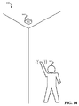
ユーザがハザード検出器によって呈示されたステータスを見て、ステータスに満足するか、そうでなければ無関心である場合には、ユーザは他のアクションを実行しなくてもよく、または単純に部屋を出てもよく、または寝てもよく、またはそうでなければ自分の一日を続行してもよい。しかしながら、いくつかの状況では、ユーザはステータスについてのより多くの情報を所望してもよい。たとえば、ハザード検出器が黄色ステータスを呈示する場合、ユーザは、ステータスについての1つ以上の詳細を知ることを望んでもよい。ステータスが呈示された後、予め定められる期間の間、ハザード検出器は、ユーザがハザード検出器の付近で任意の身振り手振りを実行したかどうかを判断することができるモーション検出器を起動してもよい。たとえば、ハザード検出器が天井に取付けられている場合、ハザード検出器より下で、またはそうでなければ近くで、ユーザは1回または複数回を手を振って、ハザード検出器をトリガして、先に表示されたステータスについての詳細を与えさせてもよい。身振り手振りが検出される場合、視覚的な指標を出力するのではなく、ハザード検出器は聴覚的なメッセージを出力してもよい。たとえば、聴覚的なメッセージは、ハザード検出器のステータスについてのさらなる詳細を示す、話言葉メッセージであってもよい。例として、ハザード検出器は、「バッテリが低い。貴方の最も早期の都合のよい時にバッテリを置換してください。」と述べてもよい。ユーザに話されるステータスについての詳細をトリガするために身振り手振りを用いる能力は、特にハザード検出器が天井に搭載されるような手の届かないところにある場合、有用かもしれない。 If the user sees the status presented by the hazard detector and is satisfied or otherwise indifferent, the user may not take any other action or simply leave the room. You may sleep or sleep, or you may continue your day. However, in some situations, the user may want more information about the status. For example, if the hazard detector presents a yellow status, the user may want to know one or more details about the status. After the status is presented, the hazard detector may activate a motion detector that can determine whether the user has performed any gesture gesture in the vicinity of the hazard detector for a predetermined period of time. Good. For example, if the hazard detector is mounted on the ceiling, the user may wave one or more times to trigger the hazard detector below or near the hazard detector, Details about the previously displayed status may be given. If a gesture gesture is detected, the hazard detector may output an audible message instead of outputting a visual indicator. For example, the audible message may be a spoken message that provides further details about the status of the hazard detector. As an example, a hazard detector may state that "the battery is low. Replace the battery at your earliest convenience." The ability to use gestures to trigger details about the status spoken to the user may be useful, especially when the hazard detector is out of reach such that it is mounted on the ceiling.
図1は、ハザード検出器100の実施の形態のブロック図を示す。ハザード検出器100は、処理システム110、ハザードセンサ120、光センサ130および発光体140を含んでもよい。このブロック図はハザード検出器100の単純化であることが理解されべきであり;他のコンポーネントも存在してもよい。たとえば、ハザード検出器100は、何らかの形式の電源を必要とする。別の例として、ハザード検出器100はおそらく、危険の存在がハザードセンサ120によって検出されると大きなノイズを出すように構成された何らかの形式の音声形成器を含む。
FIG. 1 shows a block diagram of an embodiment of a
ハザードセンサ120はハザード検出器100の付近における危険の特定のタイプを検出するように構成されてもよい。たとえば、ハザードセンサ120は、ハザード検出器100の付近における煙の存在または一酸化炭素の存在を検出するように構成されてもよい。ハザード検出器100は、単一のハザードセンサ120を有しているように示されているが、複数のハザードセンサが存在してもよいことが理解されるべきである。たとえば、ハザード検出器100は煙センサおよび一酸化炭素センサの両方を含んでもよい。いくつかの実施の形態では、複数の形式の煙センサが存在してもよい。たとえば、イオン化に基いた煙センサが存在してもよく、さらに、光電煙センサが存在してもよい。各々のそのようなタイプの煙センサはさまざまな形の火炎(たとえば、急速に火炎を発する炎、ゆっくりくすぶる炎)を検出するために好ましいかもしれない。他の形式のハザードセンサが、ハザードセンサ120として用いることが可能かもしれないことが理解されるべきであり;たとえば、ハザードセンサ120は、アンモニウム、揮発性有機化合物、湿度、温度、または付近でユーザもしくは設備を脅かす任意の他の環境条件の存在を検出するように構成されてもよい。1つ以上のハザードセンサが存在するかどうかにかかわらず、データは処理システム110に転送されてもよい。たとえば、ハザードセンサ120が煙の存在を検出する場合、煙の存在を示すデータがハザードセンサ120によって処理システム110に転送されてもよい。ハザードセンサ120は、さらにハザードセンサ120が適切に機能しているかどうか示すデータなどのような付加的情報を処理システム110に与えることができてもよい。いくつかの実施の形態では、処理システム110が、ハザードセンサ120に対して、ハザードセンサ120にセルフテストを実行させる信号を送信することが可能であってもよい。
The
光センサ130はハザード検出器100の周囲環境における光の明るさレベルを検出するように構成されてもよい。光センサ130は、処理システム110に、ハザード検出器100の周囲環境の明るさを示すデータを与えてもよい。いくつかの実施の形態では、処理システム110に明るさレベルを与えるのではなく、光センサ130は、しきい値明るさレベルがハザード検出器100の周囲環境の明るさによっていつ到達されたかを処理システム110に示してもよい。いくつかの実施の形態では、明るさがいつしきい値明るさ値より下に落ちるかに関して、しきい値明るさ値を監視して、ハザード検出器100のステータスチェックをトリガしてもよい。
The
発光体140は、複数の色の光を出力するように構成される、発光ダイオード(LED)のような1つ以上の照明要素を含んでもよい。さらに、発光体140はさまざまなパターンの光を出力するように構成されてもよい。たとえば、発光体140は、緑色光、黄色光、赤色光、青色光および白色光を出力するように構成されてもよい。さらに、発光体140は点滅し、(この文献でさらに記載され、ハロースイープ効果とも呼ばれる)循環効果を生じさせ、および/または徐々にオンおよびオフするように構成されてもよい。
The
処理システム110は、ハザードセンサ120、光センサ130および発光体140と通信状態にあってもよい。処理システム110は、ハザードセンサ120および光センサ130からデータを受けるように構成され、発光体140の発光を制御するよう構成される、1つ以上のプロセッサを含んでもよい。処理システム110は光センサ130からデータを受信してもよい。処理システム110は、光センサ130から受信されたデータを用いて、いつハザード検出器100の周囲環境における明るさがしきい値明るさレベルより下に落ちたかを判断するよう構成されてもよい。したがって、処理システム110は、光センサ130からのデータで受信された明るさ情報との比較のために用いられるしきい値明るさレベルを記憶してもよい。処理システム110はさらに、最後にステータスチェックが行なわれたかのはいつだったか、および/または最後にハザード検出器100の周囲環境における明るさレベルがしきい値明るさレベルより下に落ちたのはいつだったか監視するように構成されてもよい。いくつかの実施の形態では、処理システム110は、周期的にハザード検出器100の1つ以上のコンポーネントのステータスチェックを実行する(および恐らくはリモートサーバによって記憶されたハザード検出器100のユーザのアカウントをチェックする)。いくつかの実施の形態では、周期的にステータスチェックを実行するのではなく、処理システム110は、光センサ130によって検出される周囲の明るさがしきい値明るさレベルより下に落ちることに応答してステータスチェックを実行してもよい。
The
処理システムはハザードセンサ120のステータスをチェックするよう構成されてもよい。たとえば、処理システム110はハザードセンサ120に対して照会を行なって、ハザードセンサ120が適切に機能しているかどうかを判断するよう構成されてもよい。ある実施の形態では、処理システム110は、ハザードセンサ120の期限が切れているかどうかを判断するよう構成される(たとえば、煙検出器は7年間などのような予め定められた時間の量の間だけ機能し得ると考えられてもよい)。
The processing system may be configured to check the status of the
処理システム110は、ハザードセンサ120に加えて、またはそれと代替的に、ハザード検出器100の1つ以上のコンポーネントのステータスをチェックするよう構成されてもよい。たとえば、処理システム110は、ハザード検出器100のオンボードバッテリのバッテリレベルをチェックするよう構成されてもよい。処理システム110によって実行されるステータスチェックに応答して、処理システム110は、判断されたステータスに対応する光の色のアニメーションパターンおよび/または速度を判断するよう構成されてもよい。
The
処理システム110は、判断された光の色、パターン、および/または速度に従って発光体140を発光させてもよい。発光体140は、ハザード検出器100の付近においてユーザにステータスチェックの結果を伝えるために、2、3秒のなどのような予め定められた時間の量の間、光の色、パターン、および/または速度に従って発光されてもよい。ある実施形態では、ステータスは、光のアニメーションが1秒間徐々に明るくなること、1秒間完全な明るさにあること、および1秒間徐々に消えることの一部として呈示される。そのような迅速な呈示はバッテリの寿命を節約することを助ける。
The
図2は、ハザード検出器200の実施の形態の別のブロック図を示す。ハザード検出器200はハザード検出器100のより詳細な実施の形態を表わしてもよい。ハザード検出器200は、処理システム110、一酸化炭素センサ121、煙センサ122、光センサ130、発光体140、バッテリに基づく電源210、ユーザ入力モジュール222、構造物光源220、モーションセンサ225、無線通信モジュール230、および音声出力モジュール240を含んでもよい。
FIG. 2 shows another block diagram of an embodiment of a
ハザード検出器100は単一のハザードセンサ120を有するとして示されていたが、ハザード検出器200は2つのハザード検出器、つまり一酸化炭素センサ121と煙センサ122とを有する。明らかにするために一酸化炭素センサ121は一酸化炭素を検出するよう構成されてもよく、煙センサ122は煙を検出するよう構成されてもよい。ある実施の形態では、複数の形式の煙センサが存在し、イオン化センサと光電センサとを含む。一酸化炭素センサ121および煙センサ122は、処理システム110に対して危険の存在の指示を与えてもよい。
Although the
光センサ130および発光体140は、ハザード検出器100に関係して詳述されるように機能してもよい。
ハザード検出器200は、バッテリに基づく電源210および構造物電源220を含むとして示される。ハザード検出器200のある実施の形態では、そのような構成が存在してもよい。構造物電源220を用いて、そのような電力が存在するときにハザード検出器200に電源を供給してもよい。構造物電源220は、構造物中にわたって位置する1つ以上のハザード検出器にACまたはDC電圧源を与えるよう構成される構造物(たとえば家屋、ビルディング、オフィスなど)内においてハードワイヤードのコネクタを表わしてもよい。ACまたはDC電力がかなりの割合の時間(たとえば時間の99.5%)利用可能であり得るが、ハザード検出器200が設置される構造物における電力が利用可能でない(たとえば停電中など)場合に、ハザード検出器200が機能し続けることは望ましいであろう。したがって、バッテリに基づく電源210も存在してもよい。バッテリに基づく電源210は、構造物電源220が利用可能でないときにハザード検出器200のさまざまなコンポーネントに電力を供給するよう構成される1つ以上のバッテリを含んでもよい。ハザード検出器200のある実施の形態では、構造物電源220は存在しない。したがって、ハザード検出器200は、ハザード検出器200のコンポーネントに電力を供給するのに、バッテリに基づく電源210に永久的に依存してもよい。構造物電源220およびバッテリに基づく電源210は、図2においては、処理システム110に接続されるように示される。処理システム110は、構造物電源220が利用可能であるかどうかを判断し、バッテリに基づく電源210の充電レベルをチェックするよう構成されてもよい。構造物電源220およびバッテリに基づく電源210は処理システム110と接続されるのみであるように示されるが、これは単純化のためのみであり;構造物電源220およびバッテリに基づく電源210は、ハザード検出器200のさまざまなコンポーネントに、そのようなコンポーネントに電力を与えるべく必要とされるように、接続されてもよい。
The
モーションセンサ225は、ハザード検出器200の付近における動作を検出するよう構成されてもよい。モーションセンサ225は、ハザード検出器200の付近においてユーザにより実行されてもよい1つ以上の身振り手振りを検出するよう構成されてもよい。ある実施の形態では、モーションセンサ225は、受取られる赤外線放射を検出する受動的な赤外線(PIR)センサであってもよい。たとえばモーションセンサ225は、ユーザによって実行される手振りを検出するよう構成されてもよい。ある実施の形態では、手振りが検出されるために、複数の手振りがユーザによって実行されることが必要とされ得る。ある実施の形態では、モーションセンサ225は、電力を節約するためのように、ある時間においてのみ可能化されてもよい。バッテリに基づく電源210のみが利用可能である場合には、モーションセンサ225は、ステータスが発光体140を介してユーザに出力された後、予め規定される時間期間の間のみ可能化されてもよい。したがって、モーションセンサ225を用いて、ステータスが発光体140を介して出力された後、予め規定される時間量内で身振りがユーザによって実行されるかどうかを検出してもよい。構造物電源220が利用可能である場合には、モーションセンサ225は、より大きな時間量の間可能化されてもよい。たとえばモーションセンサ225を用いて、ユーザがハザード検出器200の付近内にいるときはいつでもそれを監視してもよい。そのような動作検出を用いて、照明を可能化して、ユーザがハザード検出器200の付近において見えるようにし、および/またはそのような動作検出を用いて、データを制御し、および/またはデータを構造物内においてHVACシステムに提供してもよい。構造物電源220が利用可能である場合には、モーションセンサ225は、一部の実施の形態では、ハザード検出器200の付近においてユーザによって実行される身振り手振りを監視するために、ステータスが発光体140を介して呈示された後、予め規定される時間期間の間のみ可能化されてもよい。
The
ユーザ入力モジュール222は、身振り手振りに加えて、またはそれに代わって、ユーザが処理システム110に入力を与えることができる入力コンポーネントの代替形式を表現してもよい。ユーザ入力モジュール222は、ハザード検出器200上においてボタンまたはスイッチの形式を取ってもよい。ボタンを押すかまたはスイッチを作動させることによって、ユーザは、入力を、ユーザ入力モジュール222を介して、処理システム110に与えることができる。たとえば、ユーザ入力モジュール222を用いて、ハザード検出器200によって現在鳴っている警報を不能化してもよい。
User input module 222 may represent an alternative form of input component that allows the user to provide input to
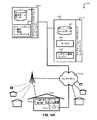
無線通信モジュール230は、処理システム110が、ハザード検出器200が設置されている構造物内に存在する無線ネットワークと通信することを可能にするよう構成されてもよい。たとえば、無線通信モジュール230は、通信のために802.11a/b/gネットワークプロトコルを用いる無線ネットワークと通信するよう構成されてもよい。無線通信モジュール230は、処理システム110がリモートサーバと通信することを許可してもよい。リモートサーバは、ハザード検出器200に関連付けられるユーザのアカウントについて処理システム110に情報を提供するよう構成されてもよい。たとえば、リモートサーバに維持されるユーザのアカウントがユーザからの注意を必要とする場合には、そのような指示が、処理システム110に対して、無線通信モジュール230を介して与えられてもよい。そのような指示は、リモートサーバに対してなされる処理システム110からの問合せに応答して、リモートサーバによって与えられてもよい。さらに、処理システム110はステータス情報をリモートサーバに送信してもよい。そのような構成は、ユーザが、コンピューティングデバイスを介してリモートサーバにログインすることによって、ステータス情報を見ることを許してもよい。
The
音声出力モジュール240は、処理システム110によって音声出力モジュール240に与えられるデータに応答して、さまざまな形式の音声を出力するよう構成されてもよい。音声出力モジュール240は、記録または合成された話し言葉メッセージを出力できるスピーカであってもよい。たとえば、危険の存在を示してもよく、またはハザード検出器200のステータスについての詳細を提供してもよい、音声に基づくメッセージが、ハザード検出器200の付近におけるユーザによって聞かれるよう、音声出力モジュール240によって出力されてもよい。音声出力モジュール240は、危険の存在に対してユーザを警戒させるよう意図される鋭いビープ音またはトーンなどのような警報音を出力するよう構成されてもよい。異なるパターンおよび/またはトーンの音を用いて、ユーザに、異なるタイプの危険に対して警戒させてもよい。ある実施の形態では、話し言葉メッセージを、音のパターンおよび/またはトーンと織り交ぜて、ユーザに、危険な存在に対して警戒させてもよい。
The
図2に呈示されるさまざまなコンポーネントと通信するよう構成されてもよい処理システム110は、ハザード検出器200の一部である。たとえば、処理システム110は、モーションセンサ225、ユーザ入力モジュール222、無線通信モジュール230、一酸化炭素センサ121、煙センサ122、バッテリに基づく電源210、構造物電源220、および/または光センサ130からデータを受信してもよい。処理システム110は、さらに、無線通信モジュール230、発光体140、および/または音声出力モジュール240を含む、ハザード検出器200のさまざまなコンポーネントにデータを出力してもよい。処理システム110は、ハザード検出器200の1つ以上のコンポーネントのステータスチェックを周期的に実行するか、または環境条件に応答して当該ステータスチェックを実行するよう構成されてもよい。たとえば、処理システム110は、バッテリに基づく電源210の充電レベルをチェックし、構造物電源220が利用可能であるかどうかをチェックし、無線通信モジュール230を介してリモートサーバに維持されるアカウントステータスを判断し、ならびに/または一酸化炭素センサ121および/もしくは煙センサ122のようなセンサが機能しているかどうかをテストするよう構成されてもよい。処理システム110は、次いで、ステータスに関する情報を、ユーザに対して、発光体140および/または音声出力モジュール240を介して出力してもよい。処理システム110は、図17〜図21に関連して詳述される方法のさまざまなブロックを実行するよう構成されてもよいことが理解されるべきである。
The
処理システム110は、(ハードウェア上で実行される)ソフトウェア、ファームウェア、および/またはハードウェアを用いて実現される複数のエンジンを含んでもよい。そのようなエンジンは、ステータスチェックエンジン251、定義参照エンジン252、出力トリガエンジン253、モーション解析エンジン254、および呈示モニタエンジン255を含んでもよい。そのようなエンジンは、より多くの数のエンジンに分割されてもよく、またはより少ない数のエンジンに組合せられてもよいことが理解されるべきである。ステータスチェックエンジン251は、1日に1回または1時間に1回など、周期的にステータスチェックを実行するよう構成されてもよい。ある実施の形態では、ステータスチェックエンジン251は、ステータス指示が出力される旨を示す出力トリガエンジン253からの指示に基づいてステータスチェックを実行するよう構成されてもよい。ステータスチェックエンジン251は、ハザード検出器の1つ以上のコンポーネントのステータスをチェックしてもよい。ステータスチェックエンジン251は、1つ以上のしきい値と比較してのバッテリに基づく電源210のバッテリレベル、一酸化炭素センサ121(たとえば機能している、機能しておらず期限が切れているなど)、煙センサ122(たとえば機能している、機能しておらず期限が切れているなど)、モーションセンサ225(たとえば機能している、機能していない)、構造物電源220(たとえば利用可能、利用不可能)、光センサ130(たとえば機能している、機能していない)、などのステータスをチェックしてもよい。ステータスチェックエンジン251は、リモートサーバに照会することによって、ハザード検出器と関連付けられるユーザアカウントのステータスをチェックしてもよい。ステータスチェックエンジン251はバッテリに基づく電源210を複数のしきい値に対してチェックしてもよい。第1のしきい値は、第2のしきい値より大きくてもよく、第1のしきい値を用いて、バッテリが低い電圧に近づきつつあり、ユーザがそれを取換えることを考えるべきである、と判断してもよい。第2のしきい値を用いて、バッテリの電圧が低く、即座に取換えるべきである、と判断してもよい。2つより多いしきい値も、バッテリ電圧を評価することに対して考えられ得る。
The
ステータスチェックエンジン251のステータスチェックの結果に基づいて、出力が定義参照エンジン252に供給されてもよい。定義参照エンジン252は、ステータスの指示を1人以上のユーザに与えるために発光体140が発光されるべき色、アニメーション、および/または速度を判断してもよい。定義参照エンジン252は、1つ以上の参照テーブルにアクセスして、判断されたステータスを表現するための適切な色、アニメーションおよび/または速度の組合わせを判断してもよい。
Based on the result of the status check of the status check engine 251, the output may be supplied to the
出力トリガエンジン253は、定義参照エンジン252によって選択された色、アニメーションおよび/または速度の適切な組合わせを用いさせて、光センサ130からのデータはハザード検出器200の周囲環境における光が記憶されたしきい値明るさレベル以下であることの指示であるという判断、および/またはステータスの指示が出力された先のときから少なくともある量の時間が経過したという判断に応答して、発光体140を発光させてもよい。呈示モニタエンジン255は、最後にハザード検出器のステータスの指示が出力されてから少なくとも記憶されたしきい値時間期間が経過したかどうかを判断してもよい。しきい値時間期間が経過していない場合には、呈示モニタエンジン255は、発光体140をステータスに基づいて発光させない指示を出力トリガエンジン253に与えてもよい。
The
モーション解析エンジン254は、(記憶されたしきい値時間期間までの間)発光体140を介するステータスの呈示中および/またはその後、活性状態であってもよい。手振りのようなある特定の身振りがモーションセンサ225からのデータに基づいてモーション解析エンジンによって識別される場合には、ステータスについての詳細が音声出力モジュール240またはハザード検出器200の何らかの他のコンポーネントを介して出力されてもよい。
The
先の詳述された実施の形態は、ハザード検出器の環境における炎、煙または一酸化炭素などのような危険を検出するよう構成されるハザード検出器に焦点を当てているが、本明細書において詳述される実施の形態は他の形式のイベントの検出に適合されてもよい。図3は、無関係のイベントに応答して機能を実行してもよいシステム300のブロック図を示す。システム300は、1つ以上の形式のイベントを検出するよう構成されてもよい。そのようなイベントは危険として適格であってもなくてもよい。システム300は、それぞれ図1および図2のハザード検出器100および/またはハザード検出器200の実施の形態を表わしてもよい。代替的に、システム300は、処理システム310、機能モジュール320、イベント検出モジュール330、および出力モジュール340を含んでもよい。
While the previously detailed embodiments focus on hazard detectors configured to detect hazards such as flames, smoke or carbon monoxide in the hazard detector environment, The embodiments detailed in may be adapted for the detection of other types of events. FIG. 3 shows a block diagram of a
機能モジュール320は、1つ以上の状態についてシステム300の付近における環境を監視することなどのような、何らかの機能を実行するよう構成されてもよい。たとえば、これらの状態は危険であってもよい。しかしながら、機能モジュール320によって監視されている1つ以上の状態は危険以外であってもよいことが理解されるべきである。たとえば、機能モジュール320は、動作、温度、湿度、および/または何らかの他の状態もしくは物体の有無を監視してもよい。機能モジュール320は、監視機能以外の何らかの機能を実行してもよい。たとえば、機能モジュール320は、何らかの他のシステムのステータスチェックを実行してもよく、または何らかの他のコンポーネントもしくはシステムを起動するよう働いてもよい。機能モジュール320は、モータ、ポンプ、医療システム、コンピューティングデバイスなどの制御などのような任意の数のさまざまな機能を実行してもよい。機能モジュール320は入力を処理システム310に与えてもよい。さらに、処理システム310は機能モジュール320のステータスをチェックするよう構成されてもよい。
The
イベント検出モジュール330は、1つ以上のタイプのイベントについてシステム300の付近を監視するよう構成されてもよい。このイベントは、処理システム310によって実行されるよう1つ以上のアクションをトリガしてもよい。たとえば、イベント検出モジュール330によって検出されるトリガ用イベントは、処理システム310に、機能モジュール320を起動させてもよく、および/または機能モジュール320などのようなシステム300の1つ以上のコンポーネントのステータスチェックを実行させてもよい。イベント検出モジュール330によって検出されるイベントは、機能モジュール320の機能とは無関係であってもよい。イベント検出モジュール330は、ユーザがシステム300についての情報を所望しそうなときと一致するイベントを検出するよう構成されてもよいが、このイベントはシステム300の任意の他の機能の実行とは無関係であってもよい。たとえば、機能モジュール320が湿度を監視している場合に、イベント検出モジュール330は、システム300の環境における明るさ、または温度、空中における化学物質もしくは他の物質の存在、動作、もしくは何らかの他のタイプのイベントもしくは条件のような何らかの他の条件に基づいてトリガするよう構成されてもよい。単純な例として、イベント検出モジュール330がシステム300の付近における明るさを監視するよう構成される場合に、システム300の付近における明るさレベルが予め規定される値に到達すると、処理システム310は、機能モジュール320のようなシステム300の1つ以上のコンポーネントおよび/またはバッテリのようなオンボード電源に対してセルフテストまたはステータスチェックを実行してもよい。出力モジュール340を用いて、セルフテストまたはステータスチェックの結果を示す出力を与えてもよい。ある実施の形態では、セルフテストまたはステータスチェックがイベント検出モジュール330によって検出されるイベントに応答して実行されるのではなく、セルフテストまたはステータスチェックは、何らかの他のスケジュールに基づいて実行されてもよいが、セルフテストまたはステータスチェックの結果の指示は、イベントがイベント検出モジュール330によって検出されたことに応答して、出力モジュール340を介して出力されてもよい。
The
イベント検出モジュール330は、ユーザがシステム300についての情報を所望しそうなときと一致するイベントを検出するよう構成されてもよい。1つの考えられ得る例は、システム300の周囲環境における光の明るさに基づく。たとえば、システム300の付近内における光が増大するとき、それは、明かりがオンにされ、システム300が存在する部屋にユーザが入ることに対応してもよい。同様に、システム300の付近内における明るさが減少するとき、それは、明かりが消されて、システム300が存在する部屋からユーザが出ることに対応してもよい。これらのイベントの両方ともが、ステータスチェックが実行されるか、またはステータスチェックの結果がユーザに出力されるための適切なときを表わしてもよい。たとえば、機能モジュール320が構造物の部屋内における状態を監視している場合には、部屋に入って明かりを点けると、ユーザはシステム300のステータスを知ることは有用であることを見出すであろう。同様に、ある状況においては、ユーザは、システム300が設置される構造物の部屋から出るとすぐにシステム300のステータスがわかることは有用であることを見出すであろう。
The
出力モジュール340は、処理システム310によって実行されるセルフテストまたはステータスチェックの指示を与えるよう構成されてもよい。出力モジュール340は、ステータスまたはセルフテストの指示を視覚的に出力するよう構成されるコンポーネントを含んでもよく、および/またはステータスもしくはセルフテストの聴覚的指示を出力するように音声を出力するよう構成されるコンポーネントを含んでもよい。たとえば、出力モジュール340は、ハザード検出器100および200との関係において詳述されるように、1つ以上のスピーカおよび/またはLEDなどのような1つ以上の発光体を含んでもよい。出力モジュール340は、処理システム310から、音声および/または視覚出力をトリガするデータを受信してもよい。ある実施の形態では、処理システム310は、出力モジュール340によって出力されるべき話し言葉メッセージを出力してもよい。システム300の実施の形態は、さらに、図2のハザード検出器200との関係において詳述されるもののようなコンポーネントを含むようさらに構成されてもよい。
図4は、ハザード検出器400の実施の形態の外部の図である。ハザード検出器400は、それぞれ図1〜図3のハザード検出器100、ハザード検出器200またはシステム300を表わしてもよい。ハザード検出器400は、ケース410、発光体420、および/または中央領域430を含んでもよい。ケース410は、壁または天井に取付けられるよう構成されるハザード検出器400の外殻を表わしてもよい。ケース410は、ハザード検出器400を通る気流を可能にして、ハザード検出器400内の1つ以上のセンサがハザード検出器400の周囲環境の空気に晒されることを許してもよい。取付けのために用いられる側とは反対側のケース410の側には、発光体420が存在してもよい。発光体420はLEDなどのような1つ以上の光源を含んでもよい。発光体420は、さまざまな色および/またはさまざまな発光パターンを、おそらくはそのようなパターンがさまざまな速度で呈示される状態で呈示するよう構成されてもよい。たとえば、発光体420は、循環効果、点滅、および/または消光を生じさせるように見える発光パターンを呈示するよう構成されてもよい。発光体420を用いてハザード検出器400のステータスに関する情報を与えてもよい一方で、発光体420を、さらに用いて、周囲の照明を与えてもよい。たとえば、ハザード検出器400によって動作が検出され、周囲の照明がしきい値よりも下であると判断された場合に、ステータスと関連付けられない色が発光体420によって出力されてもよい。さらに、ある実施の形態ではハザード検出器400は、そのような特徴がユーザによって可能化もしくは不能化されているかどうか、および/または(たとえばユーザがハザード検出器400を寝室内に設置されているとして分類したかどうかを判断することによって)ハザード検出器400が寝室に設置されているかどうかを判断してもよい。
FIG. 4 is an external view of an embodiment of the
発光体420は円形(またはハロー)として示されているが、ハザード検出器400の他の実施の形態では、他の形状を発光体420のために用いてもよいことが理解されるべきである。たとえば、発光体420は、楕円形、四角形、三角形、何らかの他の幾何学的形状、何らかの他の抽象的な形状、または線であってもよい。同様に、一部の実施の形態では、ケース410は、丸められた縁部を有する方形または矩形である。そのような設計は見て楽しい一方で、幾何学的または抽象的の両方である他の形状を用いてハザード検出器400の機能コンポーネントを収容してもよい。ある実施の形態では、発光体420は、ハザード検出器400内で生成された光を反射するケースの窪んだ部分を表わしてもよい。たとえば、1つ以上のLEDがケース410内において中央領域430の後ろなどに位置してもよく、発光体420の形状でケース410の窪んだ部分から反射される光を出力してもよい。
Although
中央領域430は、レンズを含んでもよく、それをモーションセンサと関連して用いることにより、ユーザが存在するかどうかを判断し、および/または身振り手振りがユーザによって実行されたかどうかを検出してもよい。中央領域430は、二重の機能を供してもよく、つまり、レンズとして、およびハザード検出器440に入力を与えるようユーザによって押されることができるボタンとして、機能してもよい。ある実施の形態では、中央領域430はボタンのみである。中央領域430がボタンである場合には、中央領域430を発光体420によって丸く取囲むことによって、発光体が発光されたときにユーザが暗い環境においてボタンを見つけ出すことを容易にしてもよい。そのような状況においては、ユーザは、ボタンを作動させるために、光の円または発光体420によって規定される他の領域内を押すだけでよいであろう。
The
図5は、複数の発光素子を発光体の一部として用いるハザード検出器500の実施の形態の外部の図である。ハザード検出器500においては、複数のLEDを発光体520の一部としての発光素子として用いる。ハザード検出器500は図4のハザード検出器400の実施の形態を表わしてもよい。ハザード検出器500は、それぞれ図1〜図3のハザード検出器100、ハザード検出器200、またはシステム300を含んでもよい。発光体520は複数のLEDを含んでもよい。図5においては、発光体520は26個のLEDからなる。図5に示されるLEDの数は単なる例示であることが理解されるべきである。たとえば、より少ない数またはより多い数のLEDを用いて発光体520を形成してもよい。特定の例として、5つのLEDを発光体520の一部として用いてもよい。複数のLEDを用いることによって、発光体520の一部のみが所与の時間に発光され、ならびに/または発光体520のさまざまな部分が所与の時間に異なる色および/もしくは異なる明るさレベルで発光される、さまざまな発光効果が形成されてもよい。一例として、発光体520のLEDは、光を生成しないことから、規定された明るさレベルまで徐々に明るくなり、次いで、即座に、または規定された時間期間の後、光を生成しないことに徐々に戻ってもよい。
FIG. 5 is an external view of an embodiment of a
ある実施の形態では,LEDを発光体520の一部として用いてもよく、それはケース510上に存在してもよい。他の実施の形態では、蛍光または白熱技術を用いる光源などのような、可視光を形成する他の形式のコンポーネントをLEDの代わりに用いてもよい。さらに、発光体520は、図5においては、円形に配置されるとして示される。他の実施の形態では、発光体520は、楕円形、方形、矩形、線形または何らかの抽象的な形状のような他の形状に配置されてもよいことが理解されるべきである。
In some embodiments, an LED may be used as part of the
図6は、円形パターンの光を出力するハザード検出器の実施の形態の外部の図を示す。ハザード検出器600は、図6においては2段階で示されているが、図5のハザード検出器500および/または図4のハザード検出器400を表わしてもよい。ハザード検出器600は、それぞれ、図1〜図3のハザード検出器100、ハザード検出器200、またはシステム300を含んでもよい。図6は、発光効果を出力するハザード検出器600を示す。この発光効果は(大まかに)円形パターンで出力され、循環効果またはハロー効果とも称され得る。
FIG. 6 shows an external view of an embodiment of a hazard detector that outputs a circular pattern of light. Although the
ハロースィープ効果とも称されるこの発光効果は、発光体520の、LEDのような、さまざまな発光素子が所与の時間に異なる明るさレベルで発光されることによって引起され得る。発光体520の発光素子は逐次発光され、次いで徐々に消光される。この効果は、光の点が尾を伴って発光体520の周りをスピンするように見える結果となる。ハザード検出器600を見るユーザは循環またはハロー効果を見て、発光効果および/または発光体520によって出力されている光の色に基づいてハザード検出器のステータスを理解してもよい。ある実施の形態では、循環効果が出力されているとき、発光体520の各発光素子は同じ色を出力してもよく、または複数の色が異なる発光素子によって出力されてもよい。仮想の矢印601は循環効果を示し、反対方向も可能である。発光素子が図6においてより暗く影を付けられれば付けられるほど、発光素子はより明るく発光されてもよい。したがって、ある実施の形態では、第1の発光素子は明るくてもよく、一方、そのすぐ後ろの発光素子は僅かにより暗くてもよい、などとなる。仮想の矢印602はハザード検出器600の循環効果を、異なる発光素子が今度は最も明るい発光素子であり、後の発光素子が漸進的により明るくなく発光される、後のときにおいて示す。
This light-emitting effect, also referred to as the Hello Sweep effect, can be caused by the various light-emitting elements, such as LEDs, of the
図7は、円形に配置される発光素子700の実施の形態を示す。そのようなパターンの発光素子(たとえばLEDライト)は、ハザード検出器の周方向に配置されたリング部分上に結合されてもよい。そのようなパターンは5つの発光素子:発光素子702、704、706、708および710を含み得る。発光素子700はある数のパターンに従ってオンおよびオフにされてもよく、各々は異なる色相範囲を介して循環してもよい。発光素子の各々の色も、さらなるさまざまな視覚的効果を提供するために変動してもよい。5つの発光素子が示されているが、より少ない数またはより多い数の発光素子がハザード検出器または何らかの他の形式の装置の発光体として組入れられてもよいことが理解されるべきである。
FIG. 7 shows an embodiment of a
図8A〜図8Dはハザード検出器の発光体を用いて生成されてもよい(アニメーションとも称される)4つの視覚的効果の実施の形態を示す。図8Aは、発光素子702、704、706、708および710(図7に示される)のすべてが同時にオンおよびオフにされるときに形成されてもよいパルス状効果の表現を示す。代替的に、発光素子702、704、706、708および710のすべてが、それら各々が生じさせる光の明るさを、パルス状効果を形成するよう同期された態様で増大および低減してもよい。
FIGS. 8A-8D illustrate four visual effect embodiments (also referred to as animations) that may be generated using hazard detector illuminants. FIG. 8A shows a representation of a pulsed effect that may be formed when all of the
図8Bは、回転効果を形成するよう発光素子702、704、706、708および710のすべてが時計回り方向にシーケンシャルにオンおよびオフされるときに形成されてもよい(循環効果またはハロースィープ効果とも称される)回転効果の表現を示す。さらに、発光体をオンおよびオフにすることは徐々になされてもよい。たとえば、発光素子704を徐々にオフにし、発光素子702を徐々にオンにし、一方で発光素子706、708および710は等しい明るさでオンにされる。図10は、ある実施の形態に従って図8B(および図6)の回転する視覚的効果のさらなる表現を示す。左から右に見て、図10は、新たな光が回転する視覚的効果の一方端でオンになり、他の光が回転する視覚的効果の他方端で徐々にオフになるのを示す。シーケンシャルな表現の各々のハッチングされたパターンは回転する光が回転シーケンス中にどのように色を変化させ得るかを示す。発光素子702、704、706、708および710は各々個々に異なる色であってもよいが、色付けられた光の混合によって、回転する視覚的効果の色は視覚的効果の過程で常に変化する。
FIG. 8B may be formed when all of the
図8Cは、(図7に示される)発光素子700が側部から側部への方向においてオンおよびオフにされるときに形成されてもよい波状視覚的効果の表現を示す。たとえば、図8において示されるように所与の時間の点において、発光素子710が最も明るく、発光素子708および702が次に最も明るく、発光素子706および704が最も明るくなくてもよい。その後間もなく、発光体は明るさを線形の態様で徐々に変化させ、発光素子704および706が最も明るく、発光素子708および702が次に最も明るく、発光素子710が最も明るくないようにしてもよい。
FIG. 8C shows a representation of a wavy visual effect that may be formed when the light emitting device 700 (shown in FIG. 7) is turned on and off in the side-to-side direction. For example, as shown in FIG. 8, at a given time point, light emitting
図8Dは、発光素子700の各々が、色相範囲パターンを介して、各発光素子の色相範囲パターンが発光体のすべてと同期していない状態で循環するときに形成され得る微光視覚的効果の表現を示す。図11は、ある実施の形態に従って、微光視覚的効果のために発光素子700の各々と関連付けられる異なる色相範囲パターンを示す。発光素子702、704、706、708および710が同期を外れる程度は、微光視覚的効果の変動を形成するために変動されてもよい。
FIG. 8D shows a low light visual effect that can be formed when each of the
図9Aおよび図9Bは、ハザード検出器の発光体を用いて生成されてもよいパルス視覚的効果の実施の形態を示す。図9Aは、電源オフまたは電源が利用可能でない状況に対するオンおよびオフパターンを表わし、パルスアニメーションが、気を動転させないような態様で警戒を与えるために、パルスを介して滑らかに遷移する。図9Bは、視覚的効果を介して選択可能な選択肢をユーザに呈示する際に用いられ得る左から右へのパルスパターンを表わす。たとえば、(図4の中央領域430などのような)ボタンを用いて、最初のセットアップ手順中にハザード検出器400の動作のために言語選好を選択してもよい。ユーザは、左側が英語に対してパルス化しているとき、および右側が中国語に対してパルス化しているとき、そのようなボタンを押すよう求められるかも知れない。したがって、ユーザは、ユーザの所望する選択に関連付けられる側の光がパルス化するかまたは他の態様で発光されるまで待機してもよい。ある実施の形態では、ボタンを押すのではなく、ユーザは手を1回または複数回振るなどのような身振りを実行してもよい。
9A and 9B illustrate an embodiment of a pulse visual effect that may be generated using a hazard detector illuminator. FIG. 9A represents an on and off pattern for power off or situations where power is not available, and the pulse animation transitions smoothly through the pulses to provide vigilance in a manner that does not distract. FIG. 9B represents a left-to-right pulse pattern that may be used in presenting the user with selectable options via visual effects. For example, a button (such as
さまざまな実施の形態では、上記の視覚的効果を多数の異なる態様で変動させ得る。たとえば、各効果は、ある特定の数のアニメーションサイクルに対して、より速くまたはより遅く、より明るくまたはより暗く、光の一部のみが関与する状態で、および異なる色、たとえば白、青、緑、黄、赤および/または複数色の混合を用いて、アニメーション化されてもよい。 In various embodiments, the visual effects described above can be varied in a number of different ways. For example, each effect is faster or slower, brighter or darker, with only a fraction of the light involved, and a different color, such as white, blue, green, for a certain number of animation cycles , Yellow, red and / or mixed colors may be used to animate.
これらの視覚的効果は、さまざまな特定化された目的のために、ここに詳述されるハザード検出器によって生成されてもよい。たとえば、特定の色、アニメーション、アニメーション速度など、またはそれらの組合せは、ハザード検出器によって与えられる以下の警戒または通知:起動すること、言語を選択すること、接続に対して準備ができていること、クライアントに接続されること、ボタンが押されること、ボタンがテストのために押されること、テストへのカウントダウン、テスト進行中、テスト完了、予警報、煙警報、一酸化炭素警報、熱警報、複数基準警報、警報後消音されること、後警報、問題、夜間灯状態、リセット、シャットダウン開始、シャットダウン、安全発光、バッテリが非常に低い状態、バッテリ臨界状態、電力確認などの1つ以上を表わしてもよい。例示的に、および限定としてではなく、図12および図13は、ハザード検出器の実施の形態によって用いられてもよい視覚的効果および色のための例示的な「視覚的語彙」を表わす。 These visual effects may be generated by the hazard detectors detailed herein for a variety of specialized purposes. For example, certain colors, animations, animation speeds, etc., or a combination of the following alerts or notifications given by the hazard detector: wake up, select language, be ready for connection Connected to client, button pressed, button pressed for test, countdown to test, test in progress, test complete, pre-alarm, smoke alarm, carbon monoxide alarm, thermal alarm, Indicates one or more of multiple criteria alarms, mute after alarm, after alarm, problem, night light condition, reset, shutdown start, shutdown, safety light emission, very low battery condition, battery critical condition, power check, etc. May be. By way of example and not limitation, FIGS. 12 and 13 represent an exemplary “visual vocabulary” for visual effects and colors that may be used by embodiments of the hazard detector.
図11は、ある実施の形態に従って、微光視覚的効果のために発光素子700の各々に関連付けられるさまざまな色相範囲パターンを示す。発光素子(図11においてはLEと省略される)702、704、706、708および710が同期しない程度は、微光視覚的効果の変動を形成するために変動されてもよい。示されるように、各発光素子は、時間が進むにつれて、2つの色相の間で明るさが増大および低減させられる。発光素子の一部またはすべてが「同期しない」というのは、発光素子が、同じパターンに従って発光しながら、異なるときにそうするという点においてである。図11に示されるパターンは、より少ない数またはより多い数の発光素子に対して適合され得ることが理解されるべきである。さらに、波形は、異なる視覚的効果を生じさせるために変更され得る。
FIG. 11 illustrates various hue range patterns associated with each of the
図12は、図1〜図6のハザード検出器のようなハザード検出器によって用いられてもよい視覚的効果に対する定義の実施の形態1200を示す。色定義1210、アニメーション定義1220、速度定義1230がハザード検出器によって記憶されてもよく、またはクラウドベースのサーバ(たとえばクラウドコンピューティングシステム1564)などのような何らかの遠隔位置からハザード検出器によってアクセス可能であってもよい。そのような色、アニメーションおよび/または速度定義は、ユーザに対して、購入時にハザード検出器とともに提供されるクイックリファレンスシートまたはマニュアルのような形式で提供されてもよい。したがって、ユーザは、特定の視覚的効果の意味を知るかまたは参照することができる。各色、アニメーションおよび速度は個別化された意味を有してもよい。たとえば、アニメーションの速度を用いて緊急度のレベルを示してもよい。アニメーションを用いて、肯定応当(「OK」)、注意が必要とされる指示、および/または何らかの他のステータスを与えてもよい。速度との関連において用いられるそのようなアニメーションは、ユーザに対して、そのアニメーションに関連付けられるステータスがどのように緊急であるかに関して警戒させてもよい。さらに、さまざまな色を組込んで、ユーザに対して、「OK」に対しては緑色、「何かが不都合であるかも知れない」または警告に対しては黄色、「何かが絶対的に不都合である」に対しては赤色など、より多くの情報を提供してもよい。他の色を他の形式のメッセージに対して用いてもよい。さらに、白など、別の色が、先に詳述されたようなある状況においてハザード検出器によって与えられる周囲照明に対する色によって用いられてもよい。例として、バッテリが、低い状態ではあるが、取換えられる必要はまだない場合には、色は、黄色であってもよく(「何かが不都合かも知れない」)、アニメーションは「これが私のステータスです」であってもよく、速度は低速であってもよい。バッテリが取換えられない場合には、速度は、ある時間の後、速く遷移してもよい。一旦バッテリが取換えられなければならなくなると、色は赤であってもよく(「何かが絶対的に不都合である」)、アニメーションは循環であってもよく(「私は貴方の注意を必要としています」)、速度は高速(または警報)であってもよい。したがって、バッテリは複数の電圧しきい値に対してチェックされてもよく−電圧が低ければ低いほど、呈示されるステータスはより緊急である。
FIG. 12 shows an
ある実施の形態では、色定義1210、アニメーション定義1220、および速度定義1230を独立して用いることにより、色、アニメーション、および速度を、ハザード検出器によって、ハザード検出器のステータスチェックに基づいて選択してもよい。参照を、色定義1210、アニメーション定義1220、および速度定義1230を用いて実行することにより、ハザード検出器によって判断されるステータスに対応する色、アニメーションおよび速度を選択してもよい。色定義1210、アニメーション定義1220および/または速度定義1230から選択された色、アニメーションおよび/または速度をハザード検出器によって用いることにより、ハザード検出器の発光体を介してステータスを出力してもよい。
In one embodiment, the
図13は、図1〜図6のハザード検出器のようなハザード検出器によって用いられてもよい視覚的効果(アニメーションとも称される)および色のさまざまな組合せの実施の形態1300を示す。そのような組合せは参照テーブルの形式でハザード検出器によって記憶されてもよく、またはクラウドベースのサーバシステム(たとえばクラウドコンピューティングシステム1564)などのような遠隔のコンピュータ化された装置からネットワークを介してアクセス可能であってもよい。一旦ステータスがハザード検出器によって判断されると、実施の形態1300に呈示されるようなテーブルを用いて、ステータスの指示を出力するために用いるアニメーション、色および/または速度を判断してもよい。色1301は赤であってもよく、色1302は黄色であってもよく、色1303は緑であってもよく、色1304は青であってもよく、色1305は白であってもよい。他の色割当ても可能である。色、視覚的効果、および/または速度の定義はハザード検出器によって記憶されてもよい。ステータスチェック中にハザード検出器によって判断された状態に応答して、ハザード検出器の処理システムは発光体を発光するのに用いる色、視覚的効果、および/または速度の適切な組合せを参照するかまたはそうでなければ判断してもよい。発光体は、次いで、判断された組合せに従って発光されて、情報を1人以上のユーザに伝えてもよい。ここでも、色およびアニメーションの定義は、ユーザに対して、購入時にハザード検出器とともに提供されるクイックリファレンスシートまたはマニュアルのような形式で提供されてもよい。
FIG. 13 shows an
図14は、ハザード検出器によって検出される身振り手振りを実行するユーザの実施の形態1400を示す。ユーザ1420は、ハザード検出器1410に入力を与えるために手を振る動作を実行している。ハザード検出器1410は、図1〜図6との関連において詳述されたもののような、先に詳述されたハザード検出器の1つを表わしてもよい。ユーザ1420によって実行される手振りはユーザの手を1回振ることまたは複数回振ることからなってもよい。示される実施の形態1400は手振りに焦点を当てているが、他の形式の身振り手振りがユーザ1420によって実行されハザード検出器1410によって検出されてもよいことが理解されるべきである。ハザード検出器1410は、ハザード検出器1410の発光体を介して情報が呈示された後、予め規定された時間の量の間、身振り手振りがユーザ1420によって実行されるのを監視してもよい。たとえば、ハザード検出器1410の発光体がちょうどステータスを呈示した場合、10秒間などのような予め規定される時間期間の間、ハザード検出器1410は身振り手振りがユーザ1420によって実行されるのを監視してもよい。この予め規定された時間期間内に身振り手振りが検出される場合には、ハザード検出器1410の発光体によって呈示されるステータスについての詳細が与えられてもよい。ステータスはまず発光体を用いて呈示されたが、ステータスについてのさらなる詳細は聴覚的情報を用いて呈示されてもよい。たとえば、話し言葉メッセージをハザード検出器1410によって大音量で再生してもよい。1つの例として、ハザード検出器1410が、発光体を介して、緑色のパルス状のステータス更新を出力し、ユーザが手を振る手振りを実行する場合には、話し言葉メッセージをハザード検出器1410によって出力して、「すべてのコンポーネントは通常通りに機能しています。」と言ってもよい。別の例として、ハザード検出器1410は発光体を介して黄色のパルス状のステータス更新を出力し、ユーザ1420が手を振る手振りを実行する場合には、話し言葉メッセージをハザード検出器1410によって出力して、「バッテリは低い状態です。バッテリを貴方の最も早いご都合のよいときに交換して下さい。」と言ってもよい。
FIG. 14 shows an
実施の形態1400においてわかるように、ユーザ1420がハザード検出器1410に物理的に達することは難しいかも知れない。したがって、ユーザがハザード検出器1410に効率よく入力を与えるためには、ユーザが、ハザード検出器1410に物理的に接触する必要なく入力を与えることができるよう、身振り手振りが好ましくあり得る。ハザード検出器1410は、モーション検出をハザード検出器1410の下の円錐領域に向けるレンズを有してもよい。そのような身振り手振りおよびモーション検出のターゲット化は、迷った動きが身振り手振りとして解釈されるのを防ぐのに好ましいかも知れない。
As can be seen in the
ハザード検出器(および他の装置)は、ここに詳述されるように、スマートホーム環境において設置されてもよい。図15は、スマートホーム環境1500の一例が示され、そこにおいては、図1−図6に関して詳述されたハザード検出器のような、ここにさらに記載される装置、方法、システム、サービスおよび/またはコンピュータプログラム製品のうちの1つ以上が適用可能である。示されるスマートホーム環境1500は構造物1550を含み、それは、たとえば、家屋、オフィスビルディング、ガレージ、移動住宅などを含み得る。アパート、コンドミニアムまたはオフィス空間などのような全体構造1550を含まないスマートホーム環境1500にも装置を統合することができることが十分に理解される。さらに、スマートホーム環境は、実際の構造物1550の外の装置を制御し、および/またはそれに結合され得る。実際、スマートホーム環境におけるいくつかの装置は、物理的に構造物1550内にある必要が全くない。たとえば、プールヒータまたは潅漑システムを制御する装置は、構造物1550の外部に位置し得る。
Hazard detectors (and other devices) may be installed in a smart home environment, as detailed herein. FIG. 15 illustrates an example of a
示される構造物1550は、互いから壁1554を介して少なくとも部分的に分離される複数の部屋1552を含む。壁1554は内壁または外壁を含み得る。各部屋は、さらに、床1556および天井1558を含み得る。装置は、壁1554、床1556または天井1558上に取付けられるか、それ(ら)と統合されるか、および/またはそれ(ら)によって支持され得る。
The illustrated
ある実施の形態では、図15のスマートホーム環境1500は、さまざまな有用なスマートホーム目的のうちの任意のものを与えるよう、互いと、および/または中央サーバもしくはクラウドコンピューティングシステムと途切れ目なく統合し得るインテリジェントな、マルチ検知の、ネットワーク接続された装置を含む、複数の装置を含む。スマートホーム環境1500は、1つ以上のインテリジェントな、マルチ検知の、ネットワーク接続されたサーモスタット1502(以下、「スマートサーモスタット1502」と呼ぶ)、1つ以上のインテリジェントな、ネットワーク接続されたハザード検出器1504、および1つ以上のインテリジェントな、マルチ検知の、ネットワーク接続されたエントリウェイインターフェイス装置1506(以下、「スマートドアベル1506」と呼ぶ)を含んでもよい。実施の形態によれば、スマートサーモスタット1502は、周囲の環境特性(たとえば温度および/または湿度)を検出し、HVACシステム1503をそれに従って制御する。ハザード検出器1504は、危険な物質または危険な物質を示す物質(たとえば煙、炎または一酸化炭素)の存在を検出してもよい。スマートドアベル1506は、ある場所(たとえば外側ドア)への人の接近もしくはある場所からの人の退去を検出し、ドアベル機能を制御し、音声手段もしくは視覚手段を介して人の接近もしくは退去を知らせ、またはセキュリティシステムにおける設定を制御して(たとえば占有者が行き来するときにセキュリティシステムを活性化または非活性化させて)もよい。
In certain embodiments, the
いくつかの実施の形態では、図15のスマートホーム環境1500は、さらに、1つ以上のインテリジェントな、マルチ検知の、ネットワーク接続された壁スイッチ1508(以下、「スマート壁スイッチ1508」と呼ぶ)を、1つ以上のインテリジェントな、マルチ検知の、ネットワーク接続された壁プラグインターフェイス1510(以下、「スマート壁プラグ1510」と呼ぶ)とともに、含む。スマート壁スイッチ1508は、周囲の照明状態を検出し、部屋占有状態を検出し、1つ以上の照明の出力および/または薄暗い状態を制御してもよい。いくつかの例では、スマート壁スイッチ1508は、さらに、天井ファンなどのファンの出力状態または速度を制御してもよい。スマート壁プラグ1510は、部屋または構内の占有を検出し、(たとえば家に誰もいない場合には電力がプラグに供給されないように)1つ以上の壁プラグに対する電力の供給を制御してもよい。
In some embodiments, the
さらに、さらなるいくつかの実施の形態においては、図15のスマートホーム環境1500は、冷蔵庫、ストーブおよび/またはオーブン、テレビ、洗濯機、乾燥機、照明、ステレオ、インターコムシステム、ガレージ扉開閉器、床ファン、天井ファン、壁空調装置、プールヒータ、潅漑システム、セキュリティシステム、などのような、複数のインテリジェントな、マルチ検知の、ネットワーク接続された機器1512(以下、スマート機器1512)を含む。実施の形態によれば、ネットワーク接続された機器1512は、機器のそれぞれの製造業者と協働することによって、スマートホーム環境と互換性があるようにされる。たとえば、機器は、暖房機器、窓ACユニット、電動ダクトベントなどであり得る。プラグを差込まれると、機器は、それがどのようなタイプの機器であるかを示すことによってなど、それ自体がスマートホームネットワークに対して告知することができ、それはスマートホームの制御と自動的に統合できる。そのような機器のスマートホームに対する通信は、当業者に公知の任意の有線または無線通信プロトコルによって容易にされることができる。スマートホーム環境は、さらに、スマート壁プラグ1510によって、粗くではあるが(ON/OFF)、制御され得る、古い従来の洗濯機/乾燥機、冷蔵庫などのような、さまざまな、通信を行なわない、旧来の機器1540を含み得る。スマートホーム環境1500は、さらに、ハザード検出器1504もしくはスマート壁スイッチ1508によって与えられるIR(赤外線)信号によって制御され得る、IR制御される壁空調機または他のIR制御される装置のような、さまざまな、部分的に通信を行なう旧来の機器1542を含み得る。
Further, in some further embodiments, the
実施の形態によれば、スマートサーモスタット1502、ハザード検出器1504、スマートドアベル1506、スマート壁スイッチ1508、スマート壁プラグ1510、およびスマートホーム環境1500の他の装置はモジュール方式であり、より古い家屋および新しい家屋に組込むことができる。たとえば、それらの装置は、2つの基本的なコンポーネント、つまりヘッドユニットと、ドッキングステーションとも称されるバックプレートとからなるモジュール方式のプラットフォームの周りに設計される。より古い住宅およびより新しい住宅などのような任意の住宅と互換性があるように、ドッキングステーションの複数の構成が提供される。しかしながら、ドッキングステーションのすべては標準的なヘッド接続構成を含み、任意のヘッドユニットが任意のドッキングステーションに取外し可能に取付けられることができる。したがって、ある実施の形態では、ドッキングステーションは、構造物への物理的な接続および住宅の電圧配線として働くインターフェイスであり、交換可能なヘッドユニットは、センサ、プロセッサ、ユーザインターフェイス、バッテリ、および装置の他の機能コンポーネントのすべてを含む。
According to embodiments, the
スマートホーム環境1500は、さらに、物理的な住宅の外側ではあるが、その住宅の近くの地理的範囲内にある装置との通信を含んでもよい。たとえば、スマートホーム環境1500は、スマートホーム環境1500内における他の装置に対して現在のプールの温度を通信するか、またはプールの温度を制御するためのコマンドを受信するプールヒータモニタ1514を含んでもよい。同様に、スマートホーム環境1500は、スマートホーム環境1500内で灌漑システムに関する情報を通信し、および/またはそのような灌漑システムを制御するための制御情報を受信する灌漑モニタ1516を含んでもよい。実施の形態によれば、住宅の郵便番号または地理的座標に基づくなどのような、スマートホーム環境1500の地理的な位置を考慮するためにアルゴリズムが提供される。地理的情報を用いて、散水のための最適な時間を判断するために助けとなるデータを得、そのようなデータは太陽の位置情報、温度、露点、住宅が位置する土地の土のタイプなどを含んでもよい。
The
ネットワーク接続性により、図15のスマートホーム装置の1つ以上は、さらに、たとえユーザが装置の近くにいなくても、ユーザがその装置と対話することを可能し得る。たとえば、ユーザは、コンピュータ(たとえばデスクトップコンピュータ、ラップトップコンピュータもしくはタブレット)または他の携帯電子装置(たとえばスマートフォン)1566を用いて装置と通信し得る。あるウェブページまたはアプリケーションは、ユーザから通信を受信し、その通信に基づいて装置を制御するよう、および/またはその装置の動作についての情報をユーザに呈示するよう構成され得る。たとえば、ユーザは、コンピュータを用いて、装置のための現在の設定点温度を見て、それを調整することができる。ユーザは、この遠隔通信中において構造物内にいるか、または構造物の外部にいることができる。 With network connectivity, one or more of the smart home devices of FIG. 15 may further allow a user to interact with the device even if the user is not near the device. For example, a user may communicate with the device using a computer (eg, a desktop computer, laptop computer or tablet) or other portable electronic device (eg, a smartphone) 1566. A web page or application may be configured to receive a communication from a user, control a device based on the communication, and / or present information to the user about the operation of the device. For example, the user can use a computer to view and adjust the current set point temperature for the device. The user can be inside the structure or outside the structure during this remote communication.
論じられるように、ユーザは、ネットワーク接続されるコンピュータまたは携帯電子装置1566を用いて、スマートサーモスタット、ハザード検出器1504、およびスマートホーム環境1500における他のスマート装置を制御し、それらと対話し得る。ある例では、占有者(たとえば住宅に住んでいる個人など)の一部またはすべてが彼らの電子装置1566をスマートホーム環境1500に登録することができる。そのような登録は、中央サーバにおいてなされて、占有者および/または装置が住宅と関連付けられるとして承認し、および占有者に対して装置を使用する許可を与えて住宅におけるスマート装置を制御することができる。占有者は、彼らの登録された電子装置1566を用いて、占有者が仕事中であるかまたは休暇中であるときなどに、住宅のスマート装置を遠隔制御することができる。占有者は、さらに、彼らの登録された装置を用いて、占有者が住宅内でカウチに座っているときなどのように、占有者が実際に住宅内にいるときに、スマート装置を制御してもよい。電子装置1566を登録する代わりに、またはそれに加えて、スマートホーム環境1500は、どの個人が住宅に住んでおり、したがって占有者であるか、およびどの電子装置1566がそれらの個人と関連付けられているかについての推測を行なう。したがって、スマートホーム環境は、誰が占有者であり、それらの個人と関連付けられる電子装置1566に住宅のスマート装置をコントロールすることを許可するかを「知る」。
As discussed, a user may use a networked computer or portable
ある実施の形態では、処理および検知能力を含むことに加えて、装置1502、1504、1506、1508、1510、1512、1514および1516の各々(まとめて、「スマート装置」と呼ぶ)は、任意の他のスマート装置、および世界中の任意の場所でネットワーク接続される任意の中央サーバもしくはクラウドコンピューティングシステムまたは任意の他の装置とのデータ通信および情報共有が可能である。必要とされるデータ通信は、さまざまなカスタムもしくは標準無線プロトコル(セルラー、3G/4G、Wi−Fi(登録商標),ZigBee(登録商標),6LoWPAN,BLEなど)のうちの1つ以上、および/またはさまざまなカスタムもしくは標準有線プロトコル(CAT6 Ethernet(登録商標),HomePlugなど)を用いて、実行され得る。用いられ得る1つの特定の有用なプロトコルは、Thread Groupによって公表され、802.15.4, IETF IPv6, および6LoWPANに基づくThreadプロトコルである。一部の実施の形態については、直接的であるかまたはAC電力アダプタを介する家庭電源電流によって電力を供給される装置は、相対的に電力集中型であり得るWi-Fiと、Threadおよび/またはBLEなどのような1つ以上のより小電力のプロトコルとの組合せを与えられ得る。対照的に、家庭電源電流によって電力を供給されず、大容量バッテリ源に対するアクセスを有さない、電力制約される装置は、Threadおよび/またはBLEなどのような1つ以上の小電力プロトコルのみを与えられる。一部の場合においては、家庭電源電流によって電力を供給されないが、妥当に大容量のバッテリ源に対するアクセスを有する装置は、Wi-FiとThreadおよび/またはBLEのような1つ以上のより小電力のプロトコルとの組合せを、Wi-Fi通信が、短い周期的な時間間隔中のみにおいて(たとえばログをアップロードしクラウドから更新を受信するべく1日に1回など)、特定の装置により検知されるイベント中において、または装置上のボタンを押すことなどによってユーザが装置を物理的に起動したときにオンにされるなどのように、時間的に制約されるよう制御される状態で、与えられ得る。ここに記載されるハザード検出器は2つの異なるSKUを与えられ得、一方のSKUはバッテリ補助を伴って本線電源から電力供給され、他方のSKUは相対的に大きなバッテリ源(たとえば6つのリチウムAAセル)とはいえ、バッテリのみである。このバッテリのみのSKUに対しては、ハザード検出器は、好ましくは、時間的に制約されるWi-FiとThreadおよび/またはBLEなどのような1つ以上のより小電力のプロトコルとの組合せが与えられる。
In some embodiments, in addition to including processing and sensing capabilities, each of
実施の形態によれば、スマート装置のすべてまたはいくつかは無線または有線リピータとして働くことができる。たとえば、スマート装置のうちの第1のものは無線ルータ1560を介してスマート装置のうちの第2のものと通信することができる。スマート装置は、さらに、インターネット1599などのようなネットワークへの接続を介して互いと通信し得る。インターネット1599を介して、スマート装置はクラウドコンピューティングシステム1564と通信することができ、クラウドコンピューティングシステム1564は、1つ以上の集中化または分散されたサーバシステムを含むことができる。クラウドコンピューティングシステム1564は、装置と関連付けられる製造業者、サポートエンティティまたはサービスプロバイダと関連付けられ得る。一実施の形態では、ユーザは、電話またはインターネット接続されたコンピュータなどのような他の通信手段を用いる必要なく、装置それ自体を用いてカスタマーサポートと連絡をとることができてもよい。さらに、ソフトウエア更新を、クラウドコンピューティングシステム1564から装置に(たとえば、利用可能なとき、購入されたとき、またはルーチン間隔で)自動的に送信することができる。
According to embodiments, all or some of the smart devices can act as wireless or wired repeaters. For example, a first one of the smart devices can communicate with a second one of the smart devices via
実施の形態によれば、スマート装置は、スマートホーム環境1500においてスポークスマンノードおよび小電力ノードのメッシュネットワークを形成するよう組合され、スマート装置のいくつかは「スポークスマン」ノードであり他のものは「小電力」ノードである。スマートホーム環境1500におけるスマート装置のいくつかはバッテリによって電力供給され、一方他のものはスマートホーム環境の壁1554の後ろの配線(たとえば120V線間電圧配線)に接続することなどによって、常備の信頼性のある電源を有する。常備の信頼性のある電源を有するスマート装置は「スポークスマン」ノードと称される。これらのノードは、任意の無線プロトコルまたは態様を用いて、スマートホーム環境1500におけるさまざまな他の装置のうちの任意のもの、およびクラウドコンピューティングシステム1564との双方向通信を容易にする能力を備える。他方、バッテリによって電力を供給される装置は「小電力」ノードと称される。これらのノードは、スポークスマンノードよりも小さい傾向があり、Zigbee, 6LoWPANなどのような非常に小さい電力を必要とする無線プロトコルを用いてしか通信できない。さらに、一部であって、すべてではないが、小電力ノードは双方向通信ができない。これらの小電力ノードはメッセージを送信するが、それらは「リスニング」することができない。したがって、スポークスマンノードのような、スマートホーム環境1500における他の装置はこれらの小電力ノードに対して情報を送信することができない。
According to embodiments, smart devices are combined to form a mesh network of spokesman nodes and low power nodes in a
記載されるように、スマート装置は小電力ノードおよびスポークスマンノードとして働いて、メッシュネットワークをスマートホーム環境1500において形成する。スマートホーム環境における個々の小電力ノードは、それらが何を検知しているかについての情報を定期的に送出し、スマートホーム環境における他の小電力ノードは、それら自身のメッセージを送出することに加えて、メッセージを繰返し、それによって、メッセージを、スマートホーム環境1500中においてノードからノード(つまり装置から装置)へと伝わらせる。スマートホーム環境1500におけるスポークスマンノードは小電力通信プロトコルに「ドロップダウン」して、これらのメッセージを受信し、メッセージを他の通信プロトコルに翻訳し、翻訳されたメッセージを他のスポークスマンノードおよび/またはクラウドコンピューティングシステム1564に送信することができる。したがって、小電力通信プロトコルを用いる小電力ノードは、メッセージを、スマートホーム環境1500全体にわたって、およびインターネット1563を介してクラウドコンピューティングシステム1564に送信することができる。実施の形態によれば、メッシュネットワークは、クラウドコンピューティングシステム1564が、データを住宅におけるスマート装置のすべてから定期的に受信し、そのデータに基づいて推測を行ない、スマート装置の1つにコマンドを送信し戻して、ここに記載されるスマートホーム目的の一部を達成することを可能にする。
As described, the smart devices act as low power nodes and spokesman nodes to form a mesh network in the
記載されるように、スポークスマンノードおよび小電力ノードのいくつかは「リスニング」することができる。したがって、ユーザ、他の装置、およびクラウドコンピューティングシステム1564は小電力ノードに対して制御を通信することができる。たとえば、ユーザは携帯電子装置(たとえばスマートフォン)1566を用いてコマンドをインターネットを介してクラウドコンピューティングシステム1564に送信することができ、それは、次いで、コマンドをスマートホーム環境1500におけるスポークスマンノードに中継する。スポークスマンノードは小電力プロトコルにドロップダウンして、コマンドを、スマートホーム環境中における小電力ノード、およびクラウドコンピューティングシステム1564からコマンドを直接受取らなかった他のスポークスマンノードに通信する。
As described, some of the spokesman nodes and low power nodes can be “listening”. Thus, users, other devices, and the
小電力ノードの一例はスマート夜間灯1570である。光源を収容することに加えて、スマート夜間灯1570は超音波または受動IRセンサのような占有センサ、および部屋内の光を測定する光導電性セルまたは単一画素センサなどのような周囲光センサを収容する。ある実施の形態では、スマート夜間灯1570は、部屋が暗いことをその周囲光センサが検出し、誰かが部屋にいることをその占有センサが検出すると、光源を起動するよう構成される。他の実施の形態では、スマート夜間灯1570は、単に、部屋が暗いことをその周囲光センサが検出すると光源を起動するよう構成される。さらに、実施の形態によれば、スマート夜間灯1570は、占有センサが部屋における人の存在を検知するのと同時の即時のメッセージを含む、部屋の占有および部屋における光の量に関するメッセージを定期的に送り出す小電力無線通信チップ(たとえばZigbeeチップ)を含む。上記したように、これらのメッセージは、メッシュネットワークを用いて、スマートホーム環境1500内においてノードからノードへ(つまりスマート装置からスマート装置に)、およびインターネット1599を介してクラウドコンピューティングシステム1564に、無線で送信されてもよい。
An example of a low power node is a
小電力ノードの他の例は、バッテリによって動作されるハザード検出器1504を含む。これらのハザード検出器1504は、一定であり信頼性のある(たとえば構造物の)電力に対するアクセスを伴わない領域に位置することが多く、以下に詳細に論じられるように、煙/炎/熱センサ、一酸化炭素/二酸化炭素センサ、占有/モーションセンサ、周囲光センサ、温度センサ、湿度センサなどのような任意の数およびタイプのセンサを含んでもよい。さらに、ハザード検出器1504は、それぞれのセンサの各々に対応するメッセージを、他の装置およびクラウドコンピューティングシステム1564に対して、上記のメッシュネットワークを用いることなどによって送信することができる。
Another example of a low power node includes a
スポークスマンノードの例は、スマートドアベル1506、スマートサーモスタット1502、スマート壁スイッチ1508、およびスマート壁プラグ1510を含む。これらの装置1502、1506、1508および1510は、信頼性のある電源の近くに位置し、それに接続されることが多く、したがって、任意のさまざまなプロトコルで双方向通信が可能である1つ以上の通信チップなどのような、より電力を消費するコンポーネントを含み得る。
Examples of spokesman nodes include a
ある実施の形態では、小電力ノードおよびスポークスマンノードのメッシュネットワークを用いて、非常事態のイベントにおける出口照明を提供することができる。ある例では、これを容易にするために、ユーザは、スマートホーム環境1500における出口ルートを示す前構成情報を提供する。たとえば、家屋における各部屋について、ユーザは最善の出口ルートの地図を提供する。ユーザがこの情報を提供する代わりに、クラウドコンピューティングシステム1564または何らかの他の装置が、スマートホーム家屋のアップロードされた地図、図、建築図面、およびメッシュネットワークのノードから得られる位置情報に基づいて生成された地図(たとえば装置からの位置情報を用いて家屋の地図を構築する)を用いて、ルートを自動的に判断することも考えられることが理解されるべきである。動作において、警報が活性化されると(たとえばハザード検出器1504の1つ以上が煙を検出し警報を活性化させると)、クラウドコンピューティングシステム1564または何らかの他の装置は、小電力ノードおよびスポークスマンノードから得られる占有情報を用いて、どの部屋が占有されているかを判断し、次いで、非常事態出口照明を与えるように、占有される部屋から出口ルートに沿って照明(たとえばスマート夜間灯1570、ランプに電力を供給する壁スイッチ1508、スマート壁プラグ1510など)をオンにする。
In one embodiment, a mesh network of low power nodes and spokesman nodes can be used to provide exit lighting in emergency events. In one example, to facilitate this, the user provides pre-configuration information indicating exit routes in the
図15の例示的なスマートホーム環境1500にさらに含まれ示されるのは、さまざまな家事のうちの任意のものを自律的な態様で実行するよう各々が構成されるサービスロボット1562である。一部の実施の形態に対しては、サービスロボット1562は、マサチューセッツ州ベッドフォードのiRobot, Incによって販売されるRoombaTMおよびScoobaTM製品などのような公知の市場で入手可能な装置のそれと同様の態様で、それぞれ床掃除、床洗浄を実行するよう構成され得る。床掃除および床洗浄などのような家事は、本明細書の目的に対しては「留守」または「留守中」タスクとして考えられ得、なぜならばこれらのタスクは占有者がいないときに実行されるのが一般的にはより望ましいからである。他の実施の形態については、サービスロボット1562の1つ以上は、占有者のために音楽を再生する、占有者のために局所化されたサーモスタットとして働く、占有者のために局所化された空気モニタ/清浄機として働く、局所化された新生児モニタとして働く、占有者のために局所化されたハザード検出器として働くなどのようなタスクを実行するよう構成され、なぜならば、そのようなタスクは人間の占有者が傍に存在する状態で実行されるのが一般的にはより望ましいからである。本明細書の目的のため、そのようなタスクは「対人」または「人中心」タスクとして考えられ得る。
Further included and shown in the example
占有者のために局所化された空気モニタ/清浄機として働くとき、特定のサービスロボット1562は、占有者のために「個人的健康エリアネットワーク」と呼ばれ得るものを容易にするよう考えられ得、その目的は占有者のすぐ近くの空間における空気の質を健康なレベルに保つことである。それと代替的に、またはそれと関連して、(たとえば微かに離れたセンサ、人と接触しているモニタとの近接場通信などを用いて)占有者の体温または心拍数を監視するなどのような、他の健康関連の機能を提供することができる。占有者に対して局所化されたハザード検出器として働くとき、特定のサービスロボット1562は、占有者に対して「個人的安全エリアネットワーク」と呼ばれ得るものを容易にするよう考えられ得、その目的は、占有者のすぐ近くの空間において過剰な一酸化炭素、煙、炎などがないことを確実にすることである。占有者識別およびトラッキングに関して個人的快適エリアネットワークについて上記されたものと同様の方法が、同様に、個人的健康エリアネットワークおよび個人的安全エリアネットワーク実施の形態に対しても適用可能である。
When serving as an air monitor / purifier localized for the occupant, a
ある実施の形態によれば、上に参照された、サービスロボット1562の個人的快適エリアネットワーク、個人的健康エリアネットワーク、個人的安全エリアネットワークおよび/または他のそのような対人機能の容易化は、それらの対人機能のよりよい実行を達成するための、および/またはそれらの目的をエネルギ節約態様もしくは他の資源節約態様で達成するための、規則に基づく推測技術または人工知能技術に従って、住宅における他のスマートセンサとの論理的統合によってさらに向上される。したがって、個人的健康エリアネットワークに関する1つの実施の形態に対しては、空気モニタ/清浄機サービスロボット1562は、家庭のペットが占有者の現在落ち着いている位置に向かって移動しつつあるかどうかを(たとえばオンボードセンサおよび/または他のスマートホームセンサとのデータ通信を規則に基づく推測/人工知能技術とともに用いて)検出するよう構成され得、ペットが近づいてくる場合には、より多くの空中のペットの鱗屑の到着に備えて空気清浄率を即座に増大させる。個人的安全エリアネットワークに関する他の実施の形態については、ハザード検出器サービスロボット1562は、他のスマートホームセンサによって、占有者の現在のダイニングルーム位置に近い台所において温度レベルおよび湿度レベルが上昇している旨を忠告されることができ、この忠告に応答して、ハザード検出器サービスロボット1562は、周囲煙レベルにおけるどのような小さな増大も、最も考えられるのは調理活動のためであり、真に危険な状況によるものではないという推測の下、煙検出しきい値などのような危険検出しきい値を一時的に上昇させることになる。
According to certain embodiments, the facilitating personal comfort area network, personal health area network, personal safety area network and / or other such interpersonal functions of the
一実施の形態によれば、ユーザは、共通の製造業者もしくはグループによって提供されるか、もしくはその製造業者またはグループの共通の「エコシステム」と働くよう記章を付されるなどしてもよい、関連のスマートホーム装置の一式を与えられ得、装置の各々は、実用可能である場合には、同じであるかまたは同様にトリガされる発光に基づく通知スキームまたはテーマを与え、ユーザは、各装置に対する異なるスキームを学習する必要なく、さまざまな異なる装置によって発されるステータス信号と容易に馴染むことができる。したがって、例として、セキュリティ自動化ハブ、複数ドア窓センサ、および複数のハザード検出器を含む装置の一式が提供され得、各そのような装置は、トリガされる視覚的情報を、ここに記載されるテーマおよびスキームに従って伝える円形の発光リングを有する。 According to one embodiment, users may be provided by a common manufacturer or group, or insignia to work with a common “ecosystem” of that manufacturer or group, etc. A set of related smart home devices can be provided, each of which provides a notification scheme or theme based on the same or similarly triggered emission, if practicable, and the user can Can be easily adapted to status signals emitted by a variety of different devices without having to learn different schemes for. Thus, by way of example, a set of devices including a security automation hub, multiple door window sensors, and multiple hazard detectors may be provided, each such device being described herein with triggered visual information. Has a circular luminous ring that communicates according to themes and schemes.
図16は、図15のスマートホーム環境1500のような複数のスマートホーム環境が統合され得る、拡張可能な装置およびサービスプラットフォーム1600Aのネットワークレベル図を示す。拡張可能な装置およびサービスプラットフォーム1600Aはクラウドコンピューティングシステム1564を含む。図15からの、インテリジェントな、ネットワーク接続された装置1502、1504、1506、1508、1510、1512、1514および1516の各々はクラウドコンピューティングシステム1564と通信してもよい。たとえば、インターネット1599への接続は、直接(たとえば無線搬送への3G/4G接続性を用いて)ハブ付きネットワーク1612(単純な無線ルータから、たとえばインテリジェントな専用の全住宅制御ノードまで、およびそれを含む範囲のスキームであり得る)を介してか、またはそれらの任意の組合せを介して確立され得る。
FIG. 16 shows a network level diagram of an expandable device and
ここに与えられるいくつかの例においては、装置およびサービスプラットフォーム1600Aは図15のスマートホーム環境1500のスマート装置と通信し、それらスマート装置からデータを収集するが、装置およびサービスプラットフォーム1600Aは世界中の複数のスマートホーム環境と通信しそれらの環境からデータを収集することが理解されるべきである。たとえば、クラウドコンピューティングシステム1564は1つ以上のスマートホーム環境の装置からホームデータ1602を収集することができ、装置はホームデータをルーチンで送信することができ、または特定の場合において(たとえば装置がホームデータ1602を照会するとき)ホームデータを送信することができる。したがって、装置およびサービスプラットフォーム1600Aは世界中の住宅からデータをルーチンで収集する。記載されるように、収集されるホームデータ1602は、たとえば、電力消費データ、占有データ、HVAC設定および使用データ、一酸化炭素レベルデータ、二酸化炭素レベルデータ、揮発性有機化合物レベルデータ、睡眠スケジュールデータ、調理スケジュールデータ、内部および外部温度湿度データ、テレビ視聴者数データ、内部および外部ノイズレベルデータなどを含む。
In some examples provided herein, the device and
クラウドコンピューティングシステム1564は、さらに、1つ以上のサービス1604を提供し得る。サービス1604はたとえば、ソフトウェア更新、カスタマーサポート、センサデータ収集/ロギング、遠隔アクセス、遠隔もしくは分散制御、または(たとえば、性能を向上させユーティリティコストなどを低減するために、収集されたホームデータ1602に基づいた)使用の提案を含み得る。サービス1604に関連付けられるデータは、クラウドコンピューティングシステム1564に記憶され得、クラウドコンピューティングシステム1564は、適切なとき(たとえば規則的な間隔で、ユーザから要求を受けたとき、など)にデータを検索および送信し得る。
サービス1604の一部として、ユーザアカウントがクラウドコンピューティングシステム1564によって維持されてもよい。ユーザアカウントは、ユーザアカウントとリンクされる構造物内に設置される、1つ以上のハザード検出器などのような、さまざまなスマートホーム装置と関連付けられる、加入情報、請求情報、登録情報、ユーザ選好、および/または他のデータを保存してもよい。時として、ユーザの自身のユーザアカウントに対する注意が要求される場合がある。ハザード検出器1650(または他のスマートホーム装置)からのクエリーに応答して、ハザード検出器1650によって出力されるステータスは、ユーザが自身のユーザアカウントにログインすることを要求されている旨を示すべきであることを示すメッセージが、クラウドコンピューティングシステム1564によって、(先に記載されたハザード検出器のうちの任意のものを表わしてもよい)ハザード検出器1650に送信されてもよい。要求されたログに関するさらなる詳細がサービス1604によってハザード検出器1650に送信されてもよい。たとえば、要求されるログインの理由は、(期限切れのクレジットカードなどのような、)期限切れの支払情報であってもよい。ユーザは、ハザード検出器1650の発光体を介して出力される色およびアニメーションとしてユーザに対して呈示されてもよい、ハザード検出器1650によって出力されるステータスについての詳細を要求することができる。詳細に対する要求は、ハザード検出器1650の付近内において身振り手振りを実行することによってでもよい。次いで、話し言葉メッセージがハザード検出器1650によって出力されて、ユーザが自分のアカウントにログインすることを要求されている旨を示してもよく、さらに、支払情報が更新を必要としている理由を示してもよい。したがって、ハザード検出器1650によって実行されるステータスチェックは、ハザード検出器1650それ自体のステータスをチェックするのみならず、遠隔で維持されるユーザアカウントの状態もチェックしてもよい。
As part of
図16に示されるように、拡張可能な装置およびサービスプラットフォーム1600Aの実施の形態は、処理エンジン1606を含み、それは、単一のサーバに集中されるかまたはいくつかの異なるコンピューティングエンティティの間に分散され得るが、これに限定はされない。処理エンジン1606は、データをインデックス付けし、データを解析し、および/または解析に基づきもしくは解析の一部として統計を生成するために、(たとえばインターネット(登録商標)1599またはハブ付ネットワークを介して)スマートホーム環境の装置からデータを受信するように構成されるコンピューター化されたエンジン(たとえばハードウェアによって実行されるソフトウェア)を含み得る。解析されたデータは、導き出されたホームデータ1608として記憶され得る。
As shown in FIG. 16, an embodiment of the scalable device and
解析または統計の結果はその後、結果を導き出すのに用いられるホームデータを提供した装置、他の装置、装置のユーザにウェブページを提供するサーバ、または他の非装置エンティティに送信し戻され得る。たとえば、使用統計、他の装置の使用に対する使用統計、使用パターン、および/またはセンサ読み取りを要約する統計が処理エンジン1606によって生成され送信され得る。結果または統計はインターネット1599を介して提供され得る。この態様で、処理エンジン1606は、ホームデータ1602からさまざまな有用な情報を導き出すために構成およびプログラミングされ得る。単一のサーバは、1つ以上のエンジンを含み得る。
The results of the analysis or statistics can then be sent back to the device that provided the home data used to derive the results, other devices, servers that provide web pages to device users, or other non-device entities. For example, usage statistics, usage statistics for other device usage, usage patterns, and / or statistics that summarize sensor readings may be generated and transmitted by the processing engine 1606. Results or statistics may be provided via the
ある実施の形態では、技術革新およびリサーチを促進し、ユーザに利用可能な製品およびサービスを増大させるために、装置およびサービスプラットフォーム1600Aは、ある範囲のアプリケーションプログラミングインターフェイス(API)1610を、慈善事業体、行政実体(たとえば食品医薬品局または環境保護局)、学術機関(たとえば大学研究者)、(たとえば装置保証またはサービスを関連機器に対して提供したり、ホームデータに基いた広告をターゲットとする)事業体、ユーティリティ供給会社および他の第三者などのような第三者に公開する。API1610は、第三者システムに結合され、第三者システムが、サービス1604、処理エンジン1606、ホームデータ1602、および導出されたホームデータ1608を含んで、クラウドコンピューティングシステム1564と通信することを許してもよい。たとえば、API1610は、第三者によって実行されるアプリケーションが、クラウドコンピューティングシステム1564によって実行される特定のデータ処理タスクを開始すること、ならびにホームデータ1602および導出されたホームデータ1608に対する動的な更新を受取ることを可能にする。
In one embodiment, in order to promote innovation and research and increase the products and services available to users, the device and
アカウント警戒エンジンは、ユーザのアカウントが注意を要する旨を示す指示をハザード検出器が与えるべきであるかどうかを判断するよう働いてもよい。たとえば、アカウント警戒エンジン1605は、設定が更新を必要としているかどうか、支払情報が最新であるかどうか、1つ以上のメッセージが未処理であるかどうか、支払の期日が来ているかどうかなどのようなユーザのアカウントの状態を定期的に評価してもよい。ユーザの注意が必要とされる場合には、要求がハザード検出器から受取られ、ユーザのアカウントの参照が実行されると、アカウント警戒エンジンは、ユーザアカウントが注意を必要とする旨の指示で応答してもよい。さらなる詳細も与えられてもよく、ユーザが身振り手振りを実行するかまたはそうでなければさらなる詳細を要求する場合には、そのような詳細が、聴覚的なメッセージを介してなどのように、与えられ得る。ユーザの注意が必要とされない場合には、要求がハザード検出器から受取られ、ユーザのアカウントの参照が(たとえば要求が受取られたハザード検出器と関連付けられるアカウントを判断することによって)実行されると、アカウント警戒エンジンは、ユーザアカウントは注意を要求しない旨の指示で応答してもよい。
The account alert engine may serve to determine whether the hazard detector should give an indication that the user's account needs attention. For example, the
図16Bは、図16Aの拡張可能な装置およびサービスプラットフォーム1600Aの抽象化された機能図1600Bを、特に、処理エンジン1606、および図15のスマートホーム環境1500のもののような装置を参照して示す。スマートホーム環境に位置する装置は、無限のさまざまな異なる個々の能力および限界を有するが、それらの各々がデータ消費体1665(DC)、データソース1666(DS)、サービス消費体1667(SC)およびサービスソース1668(SS)であるという点で、それらは、すべて、共通の特性を共有するとして考えられ得る。有利なことに、装置のローカルおよび直接の目的を達成するために装置に必要とされる本質的な制御情報を提供することに加えて、拡張可能な装置およびサービスプラットフォーム1600Aは、さらに、これらの装置から流れ出る大量のデータを利用するように構成され得る。装置の直接的な機能に関して装置自体の実際の動作を向上または最適化することに加えて、拡張可能な装置およびサービスプラットフォーム1600Aは、さまざまな有用な目的を達成するために、さまざまな自動化され、拡張可能であり、フレキシブルで、および/またはスケーラブルな態様でそのデータを「別の目的のために再利用する(repurposing)」ことに向けられ得る。これらの目的は、たとえば使用パターン、装置効率および/またはユーザ入力(たとえば特定の機能を要求する)に基づき、予め規定または適合的に識別されてもよい。
FIG. 16B shows an abstracted functional diagram 1600B of the extensible device and
たとえば図16Bは、ある数のパラダイム1671を含む処理エンジン1606を示す。処理エンジン1606は、一次的または二次的な装置機能を監視および管理する、管理されたサービスパラダイム1671aを含み得る。装置機能は、ユーザ入力を与えられる装置の適正な動作を保証すること、侵入者が住居にいるかもしくは住居に入ることを試みていることを推定する(たとえば、およびその場合に応答する)こと、装置に結合される機器の不良(たとえば切れた電球)を検出すること、エネルギー需要応答イベントを実現もしくはそうでなければそれに応答すること、または現在もしくは予測された将来のイベントもしくは特性に対してユーザを警戒させることを含み得る。処理エンジン1606はさらに、装置の使用に基づいて、ユーザの特性(たとえば人口学的情報)、要望および/または興味のある製品を推定する広告/通信パラダイム1671bを含み得る。サービス、プロモーション、製品またはアップグレードが、次いで、ユーザにオファーまたは自動的に提供され得る。処理エンジン1606はさらにソーシャルパラダイム1671cを含み得、ソーシャルパラダイム1671cは、ソーシャルネットワークからの情報を使用し、(たとえば装置の使用に基づいて)ソーシャルネットワークに情報を提供し、ならびに/またはソーシャルネットワークプラットフォームとのユーザおよび/もしくは装置対話に関連付けられるデータを処理する。たとえば、ソーシャルネットワーク上でのユーザに委託された連絡先に報告されるようなユーザのステータスは、光検出、セキュリティシステムの不活性化、または装置使用検出器に基づき、彼らがいつ家にいるかを示すよう更新され得る。別の例として、ユーザは、他のユーザと装置使用の統計を共有することが可能であってもよい。さらに別の例では、あるユーザは、低い電力請求を結果として生じるHVAC設定を共有してもよく、他のユーザは、自分のスマートサーモスタット1502にHVAC設定をダウンロードして、彼らの電力請求を低減してもよい。
For example, FIG. 16B shows a processing engine 1606 that includes a number of paradigms 1671. The processing engine 1606 may include a managed service paradigm 1671a that monitors and manages primary or secondary device functions. The device function is to ensure proper operation of the device given user input, to infer that the intruder is in or trying to enter the residence (eg, and responds in that case), Detecting a failure of equipment coupled to the device (eg, a broken light bulb), realizing or otherwise responding to an energy demand response event, or a user for current or predicted future events or characteristics May be alarmed. The processing engine 1606 may further include an advertising / communication paradigm 1671b that estimates user characteristics (eg, demographic information), desires, and / or products of interest based on device usage. Services, promotions, products or upgrades can then be offered or automatically provided to the user. The processing engine 1606 may further include a social paradigm 1671c that uses information from the social network, provides information to the social network (eg, based on device usage), and / or a social network platform Process data associated with user and / or device interactions. For example, user status as reported to contacts entrusted to users on social networks can be based on light detection, security system deactivation, or device usage detectors to determine when they are at home. It can be updated as shown. As another example, a user may be able to share device usage statistics with other users. In yet another example, some users may share HVAC settings that result in low power billing, while other users download their HVAC settings to their
処理エンジン1606は、挑戦/ルール/コンプライアンス/報酬パラダイム1671dを含み得、それは、挑戦、競合、ルール、コンプライアンス規則、および/もしくは報酬をユーザに通知し、ならびに/または動作データを使用して、挑戦に応じられたか、ルールもしくは規則は遵守されたか、および/もしくは報酬が得られたかどうかを判断する。挑戦、ルールまたは規則は、エネルギを節約する努力、安全に生活する(たとえば毒物または発がん性物質に晒されることを低減する)努力、金銭の節約および/または機器寿命を保護する努力、健康を改善する努力などに関し得る。たとえば、1つの挑戦は、参加者が自分のサーモスタットを1週間の間1℃だけ下げることを伴ってもよい。挑戦を成功裏に完了させたものは、クーポン、仮想通貨、ステータスなどによってのように報酬を与えられる。コンプライアンスに関しては、1つの例はレンタル不動産所有者が、賃借人はある所有者の部屋にアクセスすることは許可されない旨の規則を作ることを伴う。占有センサを有する部屋における装置は、部屋がアクセスされたときに所有者に更新を送信し得る。
The processing engine 1606 may include a challenge / rule / compliance /
処理エンジン1606は、1つ以上の処理パラダイムの機能を向上させるために、外部源からの外部情報1673を統合または別の態様で利用し得る。外部情報1673は、装置から受信されるデータを解釈し、装置の近くの環境(たとえば装置が囲まれる構造物の外部)の特性を判断し、ユーザに利用可能なサービスまたは製品を判断し、ソーシャルネットワークまたはソーシャルネットワーク情報を識別し、装置の近くのエンティティ(たとえば非常事態応答チーム、警察または病院のような公共サービス実体)のコンタクト情報などを判断し、家または近隣に関連付けられる統計的もしくは環境的条件、傾向または他の情報を識別するためなどに使用され得る。 The processing engine 1606 may integrate or otherwise utilize external information 1673 from external sources to improve the functionality of one or more processing paradigms. The external information 1673 interprets data received from the device, determines the characteristics of the environment near the device (eg, outside the structure in which the device is enclosed), determines the services or products available to the user, and social Identify network or social network information, determine contact information for entities near the device (eg emergency response teams, public service entities such as police or hospitals), statistical or environmental associated with the home or neighborhood It can be used to identify conditions, trends or other information.
驚くほどの範囲のさまざまな利点が、通常のものから重要なものまで、記載される拡張可能な装置およびサービスプラットフォーム1600Aによって引き起こされ得るとともに当該拡張可能な装置およびサービスプラットフォーム1600Aの範囲内に適合され得る。したがって、1つの「通常の」例では、スマートホーム1500の各寝室には、すべてまたは一部が占有センサを含むスマート壁部スイッチ1508、スマート壁部プラグ1510、および/またはスマートハザード検出器1504が設けられており、占有センサはさらに、(たとえばモーション検出、顔認識、可聴音パターンなどによって)居住者が眠っているかまたは起きているかどうかを推測することができる。重大な火事イベントが検知されると、遠隔セキュリティ/監視サービスまたは消防署は、各寝室に何人の居住者がいるか、それらの居住者がまだ眠っている(もしくは動かない)かどうか、または、彼らが適切に寝室から避難したどうか通知される。もちろんこれは、記載された拡張可能な装置およびサービスプラットフォームにより対応される非常に有利な能力であるが、利用可能になり得るさらに大きな「インテリジェンス」のポテンシャルを真に示し得る実質的により「重要な」例が存在し得る。恐らくより「重要な」例として、火事安全性に使用されている同じデータ寝室占有データが、さらに、近隣の子供の発育および教育の社会的規範の文脈において、処理エンジン1606によって「別の目的で再利用」され得る。したがって、たとえば、「通常の」例で論じられた同じ寝室占有および動作データが、収集され得るとともに、特定の郵便番号における生徒の睡眠パターンが識別およびトラッキングされ得る処理に利用可能になる(適切に匿名化される)ようにされ得る。これらの生徒の睡眠パターンにおける局所化された変動は、識別され、たとえば、地元の学校における異なる栄養プログラムに対して識別され相関されてもよい。
A variety of benefits in a surprising range can be triggered by the described scalable device and
さまざまな方法が、図1〜図16に関係して詳述されるシステム、装置、および他の実施例を用いて実行されてもよい。たとえば、方法は、図1〜図6に関連して詳述されるハザード検出器によって実行されてもよい。図17は、ハザード検出器のステータスを出力するための方法1700の実施の形態を示す。方法1700は、図1〜図6に関係して詳述されるハザード検出器および/または他の装置などのような、ハザード検出器によっても実行されてもよいさまざまなブロックを表わす。
Various methods may be performed using the systems, apparatus, and other embodiments detailed in connection with FIGS. For example, the method may be performed by a hazard detector detailed in connection with FIGS. FIG. 17 shows an embodiment of a
ブロック1710で、ハザード検出器の周囲環境における照明状態が解析されてもよい。そのような解析は、ハザード検出器の周囲環境における明るさレベルの1つ以上の測定値を集めたものを含んでもよい。ハザード検出器は、ハザード検出器の周囲環境における明るさのレベルを検出する1つ以上のオンボード光センサを有してもよい。ハザード検出器の周囲環境における照明状態は人工照明および/または自然照明によって影響を受けてもよい。照明状態の指示は、ハザード検出器の1つ以上の光センサによって、ハザード検出器の、1つ以上のプロセッサを含んでもよい、処理システムに与えられてもよい。ある実施の形態では、ハザード検出器の周囲環境における照明状態は、直接、統合されたプロセッサなどを介してのように、照明センサによって解析されてもよい。ブロック1710を実行するための手段は一般的にハザード検出器を含んでもよい。より具体的には、ブロック1710を実行するための手段は、プロセッサなどのような1つ以上の処理装置、および1つ以上の光センサを含んでもよい。
At
ブロック1720で、ブロック1710によって解析された照明状態は、ハザード検出器によって記憶されるしきい値明るさレベル値と比較されてもよい。この比較を用いて、照明状態は、しきい値明るさレベルに到達した周囲環境における明るさレベルを示す、と判断してもよい。ある実施の形態では、ブロック1720の判断は、ハザード検出器の周囲環境における明るさレベルはしきい値明るさレベルにまで低減したかまたはそれより下に落ちたと判断することを伴ってもよい。したがって、ある実施の形態では、ブロック1720は、ハザード検出器の周囲環境における明るさの立下がり縁はしきい値明るさレベルに合致したと判断することとして理解され得る。ブロック1720を実行するための手段は一般的にハザード検出器を含んでもよい。より具体的には、ブロック1720を実行するための手段は、プロセッサなどのような1つ以上の処理装置と、しきい値明るさレベルを記憶するためなどのような記憶媒体とを含んでもよい。
At block 1720, the lighting condition analyzed by
ブロック1730で、ハザード検出器の1つ以上のコンポーネントのステータスチェックが実行されてもよい。ある実施の形態では、ブロック1730の一部として実行されるステータスチェックはブロック1720を通して実行されてもよく、つまり、ステータスチェックは、ハザード検出器の周囲環境における明るさレベルがしきい値明るさレベルにまで低下したことを照明状態が示すと判断することに応答して実行され得る。他の実施の形態では、ステータスチェックはブロック1720とは独立して実行され、つまり、ステータスチェックは、ハザード検出器の周囲環境における照明状態がしきい値明るさレベルに到達したと判断されることに依存しない。ブロック1730において実行されるステータスチェックは、ハザード検出器の1つ以上のコンポーネントのステータスをチェックすることを伴ってもよい。たとえば、ステータスチェックはハザード検出器のバッテリ充電レベルをチェックしてもよい。バッテリ充電レベルは複数のしきい値電圧レベルと比較されてもよい。そのような複数のレベルを用いて、バッテリが十分な充電レベルを有するか、バッテリ充電レベルが低い(が、まだ交換を必要とはしない)か、またはバッテリが交換を即座に必要とするかどうかを評価してもよい。ステータスチェックは、煙センサおよび/または一酸化炭素センサなどのようなハザード検出器の1つ以上のセンサの機能をチェックしてもよい。ある実施の形態では、ステータスチェックは、ハザード検出器の1つ以上のセンサおよび/またはハザード検出器それ自体の耐用年数をチェックすることを伴う。たとえば、煙検出器および/または一酸化炭素検出器は、法律によって、7年などのような予め規定された時間量の後、耐用年数が切れることを必要とされてもよい。ブロック1730のステータスチェックは、構造物電源が設置され接続される場合、それが電力を与えているかどうかを判断することを伴ってもよい。ブロック1730のステータスチェックは、ハザード検出器から遠隔で維持されるユーザアカウントのステータスをチェックすることを伴ってもよい。これは、図15、図16Aおよび図16Bと関連して詳述されたように、リモートサーバに要求を送信して、ユーザアカウントのステータスを判断することを伴ってもよい。ユーザアカウントが注意を要する場合には、ハザード検出器は、送信された要求に応答して、おそらくはステータスの性質についての1つ以上の詳細とともに、その旨を示すメッセージを受信してもよい。ブロック1730で実行されるステータスチェックは、ハザード検出器のテストが予め規定された時間量のうちで実行されたかどうかをチェックしてもよい。たとえば、ユーザが最後にハザード検出器のテスト(可聴警報が鳴ることをテストする)を実行してから1週間、1ヶ月などのようなある量の時間があった場合には、ユーザに警告を与えることが望ましいであろう。テストがステータスチェックと異なるのは、テストはハザード検出器の1つ以上の警報器を可聴的に鳴らしてもよく、および/またはハザード検出器上に存在する1つ以上のセンサの機能をテストしてもよいという点であってもよい。ブロック1730を実行するための手段は一般にハザード検出器を含んでもよい。より具体的には、ブロック1720を実行するための手段は、プロセッサなどのような1つ以上の処理装置と、ハザード検出器200に関して詳述されるさまざまなコンポーネントの1つ以上の例のような、テストされるべき1つ以上のコンポーネントとを含んでもよい。ブロック1730を実行するための手段は、さらに、リモートサーバ、およびそのリモートサーバと通信する1つ以上のネットワークを含んでもよい。
At
ブロック1740で、ステータスチェックに基づく発光状態が選択されてもよい。発光状態は、ハザード検出器の発光体を発光させるよう、1つ以上の色、アニメーションおよび/または速度を含んでもよい。先に詳述したように、発光体はLEDなどのような1つ以上の発光素子を含んでもよい。そのような構成は、アニメーションおよび複数の色が発光体によって同時に呈示されることを可能にしてもよい。ステータスチェックの結果と関連付けられる発光状態の定義の参照テーブルまたは他の記憶構成がハザード検出器によって記憶されてもよい。たとえば、図12および図13に対応する参照テーブルを用いて、ステータスチェックに応答してハザード検出器によって呈示されるべき適切な発光状態を判断してもよい。同様に、そのような参照テーブルにおいて呈示される情報を、ユーザマニュアルまたはクイックリファレンスガイドのような形式においてのようにユーザに対して与えることにより、ユーザがさまざまな発光状態を解釈できるようにしてもよい。ブロック1730において実行されるステータスチェックの結果を用いて、ブロック1740において選択されるべき適当な発光状態を判断してもよい。ブロック1740を実行するための手段は一般にハザード検出器を含んでもよい。より具体的には、ブロック1740を実行するための手段は、プロセッサなどのような1つ以上の処理装置と、さまざまな発光状態の定義を記憶するような記憶媒体とを含んでもよい。
At
ブロック1750で、ハザード検出器の発光体を、ブロック1740で選択された発光状態に基づいて発光してもよい。ある実施の形態では、ブロック1750の実行はブロック1720次第であってもよい。つまり、ブロック1730において実行されるステータスチェックは、ハザード検出器の周囲環境における照明状態がしきい値明るさレベルに達したと判断することを条件としなくてもよいが、ステータスチェックの結果を示す発光状態を用いる発光体の発光は、ハザード検出器の周囲環境における照明状態がしきい値明るさレベルに達することに基づいてもよい。言い換えれば、ハザード検出器の周囲環境における明るさレベルを用いて、ステータスチェックの結果をいつ呈示するかを判断してもよいが、ステータスチェックをいつ実行するかは判断しなくてもよい。ブロック1730のステータスチェックがブロック1720に応答して行なわれる実施の形態のような、他の実施の形態では、ブロック1750の発光はブロック1730および1740が実行されることに応答して生じてもよい。
At
ブロック1750の発光は予め規定される時間期間の間生じてもよい。たとえば、発光体は、1秒から5秒の範囲の時間期間、または何らかの他の時間期間の間発光されてもよい。ある実施の形態では、発光体は1秒間の間徐々にオンになり、1秒間の間発光状態を呈示し、1秒間の間徐々にオフになる。ハザード検出器の周囲環境における照明状態がしきい値明るさレベルにまで減ずるのを待つことによって、ユーザはブロック1750における発光状態を、より見そうであり得、なぜならば、ハザード検出器の周囲環境は(周囲環境の先の照明状態と比較して)暗くされるからであることが理解されるべきである。一例として、ユーザがブロック1750において発光される発光体を見るかもしれないような、ありそうな状況とは、ハザード検出器がある部屋において人工光源を遮断するときである。自然光が日中によって部屋に入る場合、発光体は夜においてより発光しそうであろう。したがって、ユーザは典型的には、ステータステストを示す発光を、夜、人工光が遮断されたときに見るであろう。ブロック1750を実行するための手段は一般的にはハザード検出器を含む。より具体的には、ブロック1750を実行するための手段は、プロセッサのような1つ以上の処理装置と、1つ以上の発光素子を各々が含んでもよい1つ以上の発光体とを含んでもよい。
The light emission of
図18は、ハザード検出器のステータスを出力するための方法1800の実施の形態を示す。方法1800は方法1700の代替的な、またはより詳細な実施の形態を表わしてもよい。方法1800は図1〜図6に関連して詳述されるハザード検出器および/または他の装置のような、ハザード検出器によって実行されてもよいさまざまなブロックを表わす。
FIG. 18 shows an embodiment of a
ブロック1810および1820はそれぞれ、方法1700のブロック1710および1720と同様に実行されてもよい。そのようなブロックを実行するための手段は一般的にハザード検出器を含んでもよい。より具体的には、そのようなブロックを実行するための手段は、プロセッサなどのような1つ以上の処理装置、1つ以上の光センサ、および1つ以上の記憶媒体を含んでもよい。
ブロック1830において、少なくともあるしきい値時間期間が、先のステータスチェックから経過しているかどうか、ステータスを示すハザード検出器の発光体の先の発光から経過しているか、および/またはハザード検出器の周囲環境における明るさレベルがしきい値明るさレベルよりも下に落ちたことを照明状態が示すという先の判断から経過したかどうかについて、判断がなされてもよい。ブロック1830を用いて、ステータスチェックまたはステータスチェックの結果を示す発光状態の出力が過度に頻繁に生じないことを保証してもよい。たとえば、しきい値時間期間は1ヶ月、1週間、1日、10時間、5時間、1時間、10分、1分、または列挙された時間期間の間の何らかの他の時間期間であることが望まれてもよい。ある考えられ得る状況においては、ステータスチェックの実行および/またはステータスチェックの結果の呈示が1日に1回であることが望ましくてもよい。そのような制約は、バッテリ充電を保つこと、および/またはユーザが過度に頻繁に呈示されるステータスによって悩まされることを防ぐことを助け得る。ブロック1830を実行するための手段は一般的にハザード検出器を含んでもよい。より具体的には、ブロック1830を実行するためのステップは、プロセッサのような1つ以上の処理装置と、1つ以上の記憶媒体とを含んでもよい。
At
ブロック1840において、ステータスチェックを実行してもよい。ブロック1840のステータスチェックは方法1700のブロック1730と同様に実行されてもよい。ステータスチェックの実行が、周囲環境における明るさレベルがしきい値明るさレベルにまで落ちることを照明状態が示すことに左右される場合には、ステータスチェックの実行は、加えて、ブロック1830において、先のステータスチェックから少なくともしきい値時間期間が経過したことが判断されることに左右されてもよい。ブロック1840を実行するための手段は一般的にハザード検出器を含んでもよい。より具体的には、ブロック1840を実行するための手段は、プロセッサのような1つ以上の処理装置と、図2のハザード検出器200に関連して詳述されたさまざまなコンポーネントのうちの1つ以上の例のような、テストされるべき1つ以上のコンポーネントとを含んでもよい。
At
ブロック1850において、ハザード検出器はメッセージをリモートサーバに送信して、ユーザによって保持されるアカウントのステータスをチェックしてもよく、ハザード検出器は以前にユーザアカウントに追加され、それとリンクされている。たとえば、ユーザアカウントを用いて、特定の住宅または他の形式の構造物内に設置される、ハザード検出器を含む複数のスマートホーム装置を管理してもよい。メッセージはリモートサーバに対して大まかに周期的に(たとえば1日に1回、1週間に1回など)送信されてもよく、またはブロック1840が実行されること、ブロック1830が実行されること、および/またはブロック1820が実行されることなどのような、ある条件が生じることに応答して生じてもよい。メッセージに応答して、(図15のクラウドコンピューティングシステム1564の一部であってもよい)リモートサーバは、ハザード検出器と関連付けられるユーザアカウントのステータスをチェックしてもよい。ユーザアカウントのステータスをチェックすることは、ユーザによる最後のログインが予め規定された時間期間内にあったかどうかをチェックすること、ユーザが見るために未処理のメッセージがあるかどうかをチェックすること、ユーザの支払い情報が有効であるかどうかをチェックすること、ユーザによる見直しのために待機しているオファーがあるかどうかをチェックすること、ユーザの注意を要する設定または選好があるかどうかをチェックすること、新たなエンドユーザの同意(または他のドキュメント)がユーザによって見直される必要があるかどうかをチェックすること、および/または任意の他の形式の事項がユーザの注意を要するかどうかをチェックすることを含んでもよい。ある実施の形態では、リモートサーバは、ときどき、ハザード検出器からの要求を受信することなく、ユーザのアカウントステータスをハザード検出器に対してプッシュしてもよい。ブロック1850を実行するための手段は一般的にハザード検出器を含んでもよい。より具体的には、ブロック1850を実行するための手段は、プロセッサのような1つ以上の処理装置、無線通信モジュール、1つ以上のネットワーク、および/またはリモートサーバを含んでもよい。
At
ブロック1860において、発光状態を、ブロック1840のステータスチェックと、ブロック1850において検索されるアカウントステータスとに基づいて選択してもよい。発光状態は、ハザード検出器の発光体を発光させるよう、1つ以上の色、アニメーションおよび/または速度を含んでもよい。先に詳述したように、発光体はLEDなどのような1つ以上の発光素子を含んでもよい。そのような構成は、アニメーションおよび複数の色が発光体によって同時に呈示されることを可能にしてもよい。ステータスチェックの結果と関連付けられる発光状態の定義の参照テーブルまたは他の記憶構成がハザード検出器によって記憶されてもよい。たとえば、図12および図13に対応する参照テーブルを用いて、ステータスチェックに応答してハザード検出器によって呈示されるべき適切な発光状態を判断してもよい。同様に、そのような参照テーブルにおいて呈示される情報を、ユーザマニュアルまたはクイックリファレンスガイドのような形式においてのようにユーザに対して与えることにより、ユーザが発光状態を解釈できるようにしてもよい。ブロック1840において実行されるステータスチェックの結果およびブロック1850のアカウントステータスを用いて、ブロック1860において選択されるべき適当な発光状態を判断してもよい。ブロック1860を実行するための手段は一般にハザード検出器を含んでもよい。より具体的には、ブロック1860を実行するための手段は、プロセッサなどのような1つ以上の処理装置と、さまざまな発光状態の定義を記憶するような記憶媒体とを含んでもよい。
At
ブロック1870で、発光体を、ブロック1860で選択された発光状態に基づいて発光してもよい。ある実施の形態では、ブロック1870の実行はブロック1820および1830の判断次第であってもよい。つまり、ブロック1840において実行されるステータスチェックは、ハザード検出器の周囲環境における照明状態がしきい値明るさレベルに達した(または予め規定される時間期間が経過した)と判断することを条件としなくてもよいが、ステータスチェックの結果を示す発光状態(および/またはアカウントステータス)を用いる発光体の発光は、ハザード検出器の周囲環境における照明状態がしきい値明るさレベルに達したことおよびしきい値時間期間が経過したことに基づいてもよい。言い換えれば、ハザード検出器の周囲環境における明るさレベル、および予め規定される時間期間が経過したことを用いて、ステータスチェック(アカウントステータスチェックを含んでもよい)の結果をいつ呈示するかを判断してもよいが、ステータスチェックをいつ実行するかは判断しなくてもよい。他の実施の形態では、ブロック1870は、ブロック1840、1850および/または1860が完了したことに応答して実行されてもよい。ブロック1860を実行するための手段は一般的にハザード検出器を含んでもよい。より具体的には、ブロック1860を実行するための手段は、プロセッサのような1つ以上の処理装置と、1つ以上の発光素子を各々が含んでもよい1つ以上の発光体とを含んでもよい。
At block 1870, the light emitter may emit light based on the light emission state selected at
図17および図18の方法1700および1800はハザード検出器に焦点を当てているが、そのような方法はハザード検出器以外の装置およびシステムに適用されてもよい。図19は、無関係の環境的特性に応答して機能を実行するための方法1900の実施の形態を示す。方法1900は、ハザード検出器であってもなくてもよいシステムまたは装置によって実行されてもよいさまざまなブロックを表わす。たとえば、装置またはシステムは、温度、湿度、動作などのような状況を検知または監視するよう構成される装置であってもよい。方法1900の各ブロックはそのような装置によって実行されてもよい。
Although
ブロック1910において、環境は、トリガイベントの存在について監視されてもよい。環境は、方法1900を実行する装置の付近で監視されてもよい。たとえば、装置は、環境に存在する特性を特定するよう構成される1つ以上のセンサが設置されてもよい。この収集されたデータは、記憶された、予め規定されるトリガイベントについて監視されてもよい。その例は、温度を監視すること、湿度を監視すること、明るさを監視すること、動作を監視することなどを含む。ある実施の形態では、トリガイベントは、リモート装置またはシステムから、無線ネットワーク接続などを介して受信されてもよい。ブロック1910を実行するための手段は一般的に図3におけるような装置またはシステムを含んでもよい。より具体的には、ブロック1910を実行するための手段は、プロセッサのような1つ以上の処理装置と、1つ以上のタイプのセンサを含んでもよいイベント検出モジュールとを含んでもよい。
At
ブロック1920で、予め規定されるトリガイベントが環境において生じたと判断されてもよい。ブロック1910において環境を監視することの結果、システムによってその定義が保存される予め規定されるトリガイベントが生じたと判断されることを示すデータが集められてもよい。その例は、監視される温度がしきい値温度に到達したこと、監視される湿度が湿度しきい値に到達したこと、監視される明るさが明るさしきい値に到達したこと、動作が生じたと判断されることなどを含む。ブロック1920を実行するための手段は一般的に図3におけるような装置またはシステムを含んでもよい。より具体的には、ブロック1920を実行するための手段は、プロセッサのような1つ以上の処理装置と、1つ以上のタイプのセンサを含んでもよいイベント検出モジュールと、予め規定されるトリガイベントの定義を記憶するプロセッサ読取可能媒体とを含んでもよい。
At
ブロック1930において、機能を実行してもよい。ブロック1930において実行される機能は、予め規定されるトリガイベントが生じたと判断されることに応答して実行されてもよい。他の実施の形態では、ブロック1930において実行される機能は、予め規定されるスケジュールに従って生じてもよく、またはブロック1920のトリガイベント以外の何らかのイベントの発生に左右されてもよい。ブロック1930を実行するための手段は一般的に図3におけるような装置またはシステムを含んでもよい。より具体的には、ブロック1930を実行するための手段は、プロセッサのような1つ以上の処理装置と、(ある実施の形態においては1つ以上の処理装置であってもよい)機能コンポーネントとを含んでもよい。
At
ブロック1930の機能はブロック1920のトリガイベントと全く無関係であってもよいことが理解されるべきである。たとえば、ブロック1920のトリガイベントは、ユーザが機能のステータスを見ることを所望するときに対応しそうなイベントに基づいて選択されてもよい。たとえば、ブロック1930の機能は、セルフテスト、方法1900を実行する装置のステータスチェック、または何らかの他の形式の機能であってもよい。ブロック1910において環境が監視されブロック1920において生じたと判断される、予め規定されるトリガイベントは、このセルフテストおよび/またはステータスチェックと全く無関係であってもよい。したがって、トリガイベントは、機能がトリガイベントに応答して実行されるか否かに関わらず、ユーザが機能の結果についての情報を所望するであろうときに対するそれのありそうな相関関係に基づいて選択されてもよい。
It should be understood that the function of
ブロック1940で、実行された機能に基づいて、指示が出力されてもよい。ブロック1940における出力は、ブロック1920において判断されるように、予め規定されるトリガイベントが生じたことに左右されてもよい。したがって、実行された機能に基づく出力は、予め規定されるトリガイベントが生じたことに応答して出力されてもよく、それは機能それ自体とは全く無関係であってもよい。これの一例は、方法1700および1800のさまざまな実施の形態に見られ得る。ある実施の形態では、ハザード検出器のステータスは、ハザード検出器の環境に存在する照明状態に応答して出力される。そのような照明状態は、ハザード検出器の状態とは全く無関係であってもよい(つまり、明るさはステータスにどのような影響も有さなくてもよい)。ブロック1930の機能がブロック1920に応答して実行される実施の形態のような他の実施の形態では、ブロック1940は、ブロック1930が実行されたことに応答して実行されてもよい。ブロック1940において出力される指示はブロック1930の機能の結果を示してもよい。ブロック1940の出力は光および/または音を含んでもよい。たとえば、出力は、光の色、アニメーション、および/または速度の組合せであってもよい。出力される音は、リング音、トーン、または話し言葉メッセージを含んでもよい。振動、印刷されたメッセージ、無線メッセージの伝送などのような、他の形式の出力ももちろん可能である。ブロック1940を実行するための手段は一般的に図3にあるような装置またはシステムを含んでもよい。より具体的には、ブロック1940を実行するための手段は、プロセッサのような1つ以上の処理装置と、出力モジュール(ある実施の形態においては、スピーカおよび/または発光体を含んでもよく、それは、1つ以上の発光素子、振動装置、プリンタなどを含むことができる)とを含んでもよい。
At
方法1700〜1900のいずれかが実行された後、ユーザ入力を監視して、ユーザが、ハザード検出器または他の形式のシステムもしくは装置によって出力されるステータスについてのさらなる情報(または他の情報)を所望するかどうかを判断してもよい。図20は、ユーザ入力に応答してステータスについて詳細を提供するための方法2000の実施の形態を示す。方法2000は、ハザード検出器の状態またはステータスを出力するために方法1700〜1900または何らかの他の方法のうちの1つを実行した後に、ハザード検出器によって実行されてもよい。
After any of the methods 1700-1900 are performed, the user input is monitored for further information (or other information) about the status output by the user by the hazard detector or other type of system or device. It may be determined whether desired. FIG. 20 illustrates an embodiment of a
ブロック2010は方法1700〜1900の結果を表わしてもよい。たとえば、ブロック2010は、方法1700のブロック1750、方法1800のブロック1870、および/または方法1900のブロック1940を表わしてもよい。ブロック2010は、さらに、ステータスが出力されることの、何らかの他の指示を表わしてもよい。たとえば、ある実施の形態においてブロック2010は、方法1700〜1900の少なくとも1つが実行されることなく実行されてもよい。
ブロック2020において、ハザード検出器または他の装置は、ブロック2010でステータスが出力されることの指示の後、ユーザ入力を監視してもよい。ある実施の形態では、ブロック2020は、何らかの他の状態が生ずることによってトリガされてもよい。たとえば、照明状態が、ハザード検出器の周囲環境において、しきい値明るさレベルと一致するかまたはそれより低い明るさレベルに到達したことが、ブロック2020に対するトリガとして働いてもよく、またはブロック2010がブロック2020をトリガしてもよい。ユーザ入力を監視することは、ユーザ入力を監視するよう構成される1つ以上のセンサを起動することを含んでもよい。たとえば、モーションセンサまたは同様のコンポーネントをブロック2020のために起動して、身振り手振りがユーザによって実行されることを監視してもよい。そのような身振り手振りは、ユーザによる1回の手ぶりまたは複数回の手ぶりであってもよい。そのようなセンサは、電力を節約するために、予め規定される時間期間の間まで身振り手振りを監視するよう可能化されるのみであってもよく、それは、バッテリにより電力を供給される装置においては特に有用であろう。ユーザ入力が検出される場合には、センサは不能化されてもよく、なぜならば、即座の今後のユーザ入力は監視される必要はないからである。ブロック2020を実行するための手段は一般的にハザード検出器(または他の形式の装置)を含んでもよい。より具体的には、ブロック2020を実行するための手段は、プロセッサのような1つ以上の処理装置と、モーションセンサのような1つ以上のセンサとを含んでもよい。
At
ユーザ入力がブロック2020において受信されない場合には、方法2000はブロック2040に進んでもよい。ユーザ入力がブロック2020において受信される場合には、方法2000はブロック2030に進んでもよい。たとえば、ユーザがブロック2020において手振りを実行し、それがハザード検出器によって検出される場合には、方法2000はブロック2030に進んでもよい。ブロック2030では、ユーザ入力が検出されるかまたは他の態様で受信されることに応答して、ブロック2010において先に出力されたステータスに関する1つ以上の詳細が与えられてもよく、ブロック2030において与えられる1つ以上の詳細は、ブロック2010のステータスとは異なるモードを介して与えられてもよい。たとえば、ブロック2010において出力されるステータスは、先に記載された発光素子の色、アニメーションおよび/または速度などのような、光の形式においてであったかもしれない。ブロック2030の1つ以上のステータス詳細の出力は、音声に基づくメッセージのような、異なるモードを介してであってもよい。ある実施の形態では、ブロック2030の1つ以上のステータス詳細は、話し言葉メッセージの形式で出力される。これは、ハザード検出器が、ローカルの記憶媒体またはリモートサーバのいずれかから、スピーカを介してユーザに対して再生されるべき記録されたメッセージを検索することを伴ってもよい。詳細が出力される一方で、ブロック2020で出力されたステータスも出力されてもよく、ステータスは光の形式にあり、詳細は音声の形式にある。ブロック2030を実行するための手段は一般的にハザード検出器(または他の形式の装置)を含んでもよい。より具体的には、ブロック2030を実行するための手段は、プロセッサのような1つ以上の処理装置と、スピーカのような1つ以上の音声出力装置とを含んでもよい。ブロック2030にて出力される1つ以上のステータス詳細は音声以外の何らかの形式で出力されてもよい。たとえば、ハザード検出器が画面を有する場合には、書かれたメッセージまたは図形のインジケータが聴覚的メッセージに加えて、またはそれに代わって呈示されてもよい。
If no user input is received at
一例として、ブロック2010において、黄色の発光されるステータスがユーザに対して出力されてもよい。ユーザはそのステータスをハザード検出器の発光体によって出力される色およびアニメーションの形式で見て、ハザード検出器が何らかの形の注意を要していることを理解してもよいが、しかしながら、ユーザは、ハザード検出器の正確にはどのような局面が注意を要しているのかは、確信がないかもしれない。ユーザがその状況をそのときに処理することを望まない場合には、ユーザは、単に、身振り手振りなどの入力を与えなくてもよい。しかしながら、ユーザが、ハザード検出器のどのような局面が注意を要しているかに関する1つ以上の詳細を知りたい場合には、ユーザは、ハザード検出器上のボタンを押すか、またはハザード検出器がユーザ入力を監視している予め規定される時間期間中に1つ以上の手振りなどのような身振り手振りを実行することなどによって、入力を与えてもよい。ユーザが入力を与えることに応答して、ステータスについての1つ以上の詳細を含む聴覚的メッセージがハザード検出器によって出力されてもよい。たとえば、メッセージは、「私のバッテリは低い。あなたのご都合のよい最も早いときに交換してください。」と述べてもよい。そのようなメッセージが出力された後、ユーザは、注意を要するハザード検出器の詳細な側面、つまりバッテリは交換される必要があることを理解してもよい。ステータスの同じ指示が、ハザード検出器のさまざまな状態に対して出力されてもよいことが理解されるべきである。ある実施の形態では、ステータスに応答してユーザが入力するだけで、ユーザは、注意を必要とするハザード検出器の局面を正確に知ることができる。
As an example, in
ユーザ入力がブロック2020において受信されたかされなかったかに関わらず、ブロック2040において、ハザード検出器は1つ以上の危険について監視し続けてもよい。そのような危険は、煙および/または一酸化炭素を監視することを含んでもよい。さらに、そのような危険を監視することは方法2000中にわたって生じてもよい。方法2000の部分が実行されることに関わらず、ハザード検出器の主要な機能は、そのような危険を監視し続けることであってもよい。したがって、方法2000の間の任意の点において危険が検出される場合には、方法2000は中断されてもよく、適切な警報が鳴ってもよい。ブロック2040を実行するための手段は一般的にハザード検出器(または他の形式の装置)を含んでもよい。より具体的には、ブロック2040を実行するための手段は、プロセッサのような1つ以上の処理装置、ならびに煙および/または一酸化炭素センサなどのような1つ以上のセンサを含んでもよい。
Regardless of whether user input was received at
図21は、ユーザ入力に応答してステータスについての詳細を与えるための方法2100の実施の形態を示す。方法2100は、ハザード検出器の状態またはステータスを呈示するために方法1700〜1900または何らかの他の方法のうちの1つを実行した後に、ハザード検出器によって実行されてもよい。方法2100の各ブロックはハザード検出器によって実行されてもよい。方法2100は図20の方法2000の、より詳細な実施形態を表わしてもよい。
FIG. 21 illustrates an embodiment of a
ブロック2110は方法1700〜1900の結果を表わしてもよい。ブロック2110は、ハザード検出器の発光体が発光状態に従って発光されることを必要としてもよく、発光状態はハザード検出器のステータスを示してもよい。たとえば、ブロック2110は、方法1700のブロック1750、方法1800のブロック1870、および/または方法1900のブロック1940を表わしてもよい。ブロック2110は、さらに、ステータスが出力されることの、何らかの他の指示を表わしてもよい。たとえば、ある実施の形態においてブロック2110は、方法1700〜1900の少なくとも1つが実行されることなく実行されてもよい。
Block 2110 may represent the results of methods 1700-1900. Block 2110 may require that the hazard detector illuminant be illuminated according to the emission state, and the emission state may indicate the status of the hazard detector. For example, block 2110 may represent block 1750 of
ブロック2120において、1つ以上のモーション検出器センサが、予め規定される時間期間までの間起動されてもよい。ある実施の形態では、1つ以上のモーション検出器センサは、継続的に、または少なくとも既に起動されている。モーション検出器がブロック2120において起動される必要があるかどうかは、ハザード検出器がバッテリによるかまたは構造物電源を介して電力を供給されるかに依存してもよい。たとえば、バッテリによって電力を供給される場合には、バッテリの寿命を延ばすなどのために、電力を節約することが望ましいであろう。
At
ブロック2130において、ハザード検出器または他の装置は、ブロック2110においてステータスが出力されるという指示の後、身振り手振りがユーザによって実行されるのを監視してもよい。ある実施の形態では、ブロック2130は、何らかの他の状態が生ずることによってトリガされてもよい。たとえば、照明状態が、ハザード検出器の周囲環境において、しきい値明るさレベルと一致するかまたはそれより低い明るさレベルに到達した(たとえば減少した)ことが、ブロック2130に対するトリガとして働いてもよい。身振り手振りを監視することは手振りなどのような具体的な身振り手振りが一回または二回以上実行されること(例えば複数回の手振りが必要とされてもよい)に関してモーション検出センサの出力を監視することを含んでもよい。身振り手振りが検出される場合には、センサは不能化されてもよく、なぜならば、即座の今後のユーザ入力は監視される必要はないからである。ブロック2130を実行するための手段は一般的にハザード検出器(または他の形式の装置)を含んでもよい。より具体的には、ブロック2130を実行するための手段は、プロセッサのような1つ以上の処理装置と、モーションセンサのような1つ以上のセンサとを含んでもよい。
At
ブロック2140において、ブロック2130において監視されている身振り手振りが実行されたかどうかが判断されてもよい。身振り手振りが実行されない場合には、方法2140はブロック2160に進んでもよい。身振り手振りが実行されたと判断される場合には、方法2100はブロック2150に進んでもよい。ブロック2130を実行するための手段は一般的にハザード検出器(または他の形式の装置)を含んでもよい。より具体的には、ブロック2140を実行するための手段は、プロセッサのような1つ以上の処理装置を含んでもよい。
At
ブロック2150および2160は方法2000のブロック2030および2040と同様に実行されてもよい。したがって、身振り手振りが検出される場合には、ユーザは、ハザード検出器のステータスに関する1つ以上の詳細を与えられる。身振り手振りが検出されない場合には、ハザード検出器は、1つ以上のステータス詳細を出力することなく、危険を監視し続ける。
図22は、ステータスを、ユーザ入力およびそのステータスの重要度に基づいて出力するための方法2200の実施の形態を示す。方法2200は、方法1700、1800、2000または2100の代替的実施の形態またはより詳細な実施の形態を表わしてもよい。方法2200は、図1〜図6との関係において詳述されるハザード検出器および/または他の装置のようなハザード検出器によって実行されてもよいさまざまなブロックを表わす。方法2200のブロックは図17〜図20との関係において詳述される他の方法の一部として実行されてもよいことが理解されるべきである。
FIG. 22 shows an embodiment of a method 2200 for outputting status based on user input and the importance of the status. Method 2200 may represent an alternative or more detailed embodiment of
ブロック2205において、ハザード検出器の1つ以上のコンポーネントのステータスチェックが実行されてもよい。ある実施の形態では、ブロック2205の一部として実行されるステータスチェックは、方法1700のブロック1720(およびしたがってブロック1710)のような、他のブロックが実行されることに応答して実行される。ブロック2205の結果、ブロック1730との関連において論じられるものと同様の解析がもたらされてもよい。ブロック2205のステータスチェックは、重大ステータスチェックおよび非重大ステータスチェックの解析に分割されてもよい。非重大ステータスチェックは、バッテリが第1のしきい値充電レベルよりも低いかどうか判断すること、メッセージがハザード検出器とリンクされるユーザアカウントと関連付けられる状態でリモートサーバに存在すること、ハザード検出器がインターネットから切断されていること(そして以前は接続されていたこと)、ハザード検出器が構造物の電源から切断されていること(および以前は接続されていたこと)ならびに/または何らかの他の問題が生じたこと(英数字コードがそのような他の問題に与えられてもよい)を含んでもよい。重大ステータスチェックは、ハザード検出器の耐用年数が切れたかどうかを判断すること、ハザード検出器が故障したかどうかを判断すること、および/またはバッテリ充電レベルが(非重大バッテリ充電レベルと関連付けられる第1のしきい値よりも低い充電レベルを表わす)第2のしきい値より下であるかどうかを判断することを含んでもよい。
At
ブロック2210において、どのようなステータスチェックも、重大または非重大ステータスが否定的な結果を有する結果とならない場合には、方法2200はブロック2215に進んでもよい。このブロックでは、重大または非重大ステータスがないという視覚的指示が、パルスアニメーションなどのような穏やかなアニメーションを用いるハザード検出器の発光体の緑色の発光などのように、出力されてもよい。ブロック2215の後、ハザード検出器は、ステータスに関連するボタンの押圧または身振り手振りなどのようなユーザの入力を監視しなくてもよく、ブロック2220に進んで危険を監視し続けてもよい。
If at
ブロック2210において、ステータスチェックが、重大または非重大ステータスが否定的な結果を有する結果となる場合には(たとえばセンサが故障する、バッテリが低い、インターネット接続が失われるなど)、方法2200はブロック2225に進んでもよい。ブロック2225では、ステータスチェックが重大ステータスをもたらす結果となった場合には、方法2200はブロック2235に進んでもよい。ブロック2235では、重大ステータスを示す聴覚的警告ステータスが出力されてもよい。聴覚的警告ステータスは合成または記録された話し言葉メッセージを含んでもよい。警告メッセージは、黄色などのような警告を示す色を用いるハザード検出器の発光体の発光を伴ってもよい。高速パルス状の黄色い光のようなアニメーションを用いて、ユーザを、危険な状況に対して警戒させてもよい。
If, at
ブロック2225に戻って、ステータスチェックの結果、非重大ステータスであった場合には、方法2200はブロック2230に進んでもよい。ブロック2230では、非重大ステータスを示す純粋に視覚的な警告ステータスが出力されてもよい。警告ステータスは、黄色などのような警告を示す色を用いるハザード検出器の発光体の発光であってもよい。低速のパルス状の黄色い光などのようなアニメーションを用いて、ユーザに、準危険な状況に対して警戒させてもよい。正確な非重大警告を知るためには、ユーザはユーザ入力を与えることを必要とされてもよい。
Returning to block 2225, if the status check results in a non-critical status, the method 2200 may proceed to block 2230. At
ブロック2240では、ハザード検出器のボタンの押圧(かまたはハザード検出器上の何らかの他の物理的な装置の起動)の形式におけるような、または身振り手振りが実行されることによってのような、ユーザ入力が、予め規定される時間期間までの間、ハザード検出器によって監視されてもよい。たとえば、ハザード検出器は、ブロック2230または2235における出力されたステータスに応答して、30秒間の間入力を監視してもよい。ユーザの存在が検出された場合には、ハザード検出器の発光体を点灯して、発光されるかまたはパルス状の青色によってのように、そのような存在を示してもよい。ブロック2245において、入力が受信されたかどうかを判断してもよい。入力が受信されない場合には、方法2200はブロック2220に進んでもよい。入力が受信された場合には、ブロック2250が実行されてもよい。
At block 2240, user input, such as in the form of a hazard detector button press (or activation of some other physical device on the hazard detector) or by performing a gesture gesture. May be monitored by a hazard detector for up to a predefined time period. For example, the hazard detector may monitor the input for 30 seconds in response to the output status in
ブロック2250では、重大および/または非重大ステータスが聴覚的メッセージを介して出力されてもよい。そのようなメッセージは、記録または合成された音声がハザード検出器によって出力されることを含んでもよい。ステータスが非重大であった場合には、ブロック2250が、ステータスが音声を介して出力される1回目である。ステータスが重大である場合には、ブロック2250は(ブロック2235のため)ステータスが音声を介して出力される少なくとも2回目を表わしてもよい。聴覚的出力は、黄色などのような警告を示す色を用いるハザード検出器の発光体の発光を伴ってもよい。(非重大ステータスに対しては)低速の、または(重大ステータスに対しては)高速のパルス状の黄色い光などのようなアニメーションを用いて、ユーザを、ステータスに対して警戒させてもよい。ブロック2250の後、方法2200はブロック2245に戻って、ステータスが繰り返されることをユーザが欲しているかどうかなど、さらなるユーザ入力が受信されるかどうかを見てもよい。ブロック2240が実行されていた間に身振り手振りまたはボタンの押圧がユーザによって実行されたかどうかは、どのようにハザード検出器の発光体がブロック2250において点灯されるかを変えてもよい。たとえば、ボタンの押圧がブロック2240において受信される場合には、発光体は青色に点灯され、高速でパルス化されてもよく、身振り手振りがブロック2240において検出された場合には、発光体は、(身振り手振りが検出されたという肯定応答として働いてもよい)黄色の波状アニメーションを出力してもよい。
At
図23を参照して、特定目的コンピュータシステム2300の実施の形態が示される。たとえば、1つ以上のインテリジェントなコンポーネント、処理エンジン206、およびそのコンポーネントが、特定目的コンピュータシステム2300であってもよい。そのような特定目的コンピュータシステム2300は、ハザード検出器、および/またはリモートサーバ、スマートサーモスタットもしくはネットワークなどのような、ここに論じられる他のコンピュータ化された装置のうちの任意のものの一部として組込まれてもよい。上記の方法は、コンピュータシステムに命じて、上記の方法およびコンポーネントのアクションを実行させるコンピュータプログラム製品によって実現されてもよい。各そのようなコンピュータプログラム製品は、コンピュータシステムのプロセッサに命じて対応のアクションを実行させるコンピュータ読取可能媒体において実施される命令(コード)のセットを含んでもよい。命令は、シーケンシャルな順序で、または(異なる処理スレッド下におけるように)並列で、またはそれらの組合せにおいて実行されるよう構成されてもよい。コンピュータプログラム製品を汎用コンピュータシステム2326にロードした後、それは特別目的コンピュータシステム2300に変換される。
Referring to FIG. 23, an embodiment of a special
特別目的コンピュータシステム2300は、コンピュータ2302と、コンピュータ2302に結合されるモニタ2306と、コンピュータ2302に(選択肢的に)結合される1つ以上のさらなるユーザ出力装置2330と、コンピュータ2302に結合される(たとえばキーボード、マウス、トラックボール、タッチスクリーンなどのような)1つ以上のユーザ入力装置2340と、コンピュータ2302に結合される選択肢的な通信インターフェイス2350と、コンピュータ2302における有形のコンピュータ読取可能メモリに記憶されるコンピュータプログラム製品2305とを含む。コンピュータプログラム製品2305は、コンピュータシステム2300に命じて上記の方法を実行させる。コンピュータ2302は、バスサブシステム2390を介して多数の周辺装置と通信する1つ以上のプロセッサ2360を含んでもよい。これらの周辺装置は、ユーザ出力装置2330、ユーザ入力装置2340、通信インターフェイス2350、ならびに有形のコンピュータ読取可能メモリの形式である(たとえばディスクドライブ、光学ドライブ、ソリッドステートドライブなど)ランダムアクセスメモリ(RAM)2370および不揮発性記憶ドライブ2380などのような記憶サブシステムを含んでもよい。
Special
コンピュータプログラム製品2305は、不揮発性記憶ドライブ2380またはコンピュータ2302にアクセス可能な別のコンピュータ読取可能媒体に記憶され、ランダムアクセスメモリ(RAM)2370にロードされてもよい。各プロセッサ2360は、Intel(登録商標)またはAdvanced Micro Devices, Inc(登録商標)からのマイクロプロセッサのような、マイクロプロセッサを含んでもよい。コンピュータプログラム製品2305をサポートするために、コンピュータ2302は、コンピュータプログラム製品2305の上記のコンポーネントとの通信、およびコンピュータプログラム製品2305のサポートにおいて上記のコンポーネント間の通信を処理するオペレーティングシステムを実行する。例示的なオペレーティングシステムは、Microsoft CorporationからのWindows(登録商標)、Sun MicrosystemsからのSolaris(登録商標)、LINUX(登録商標)、UNIX(登録商標)を含む。
ユーザ入力装置2340は、コンピュータ2302に情報を入力するのに、すべての考えられ得るタイプの装置および機構を含む。これらは、キーボード、キーパッド、マウス、スキャナ、デジタル描画パッド、ディスプレイに組込まれるタッチスクリーン、音声認識システムのような音声入力装置、マイクロフォン、および他のタイプの入力装置を含んでもよい。さまざまな実施の形態においては、ユーザ入力装置2340は、典型的には、コンピュータマウス、トラックボール、トラックパッド、ジョイスティック、無線リモート、描画タブレット、音声コマンドシステムとして実施される。ユーザ入力装置2340は、典型的には、ユーザが、ボタンのクリックなどのコマンドを介して、モニタ2306上に現われるオブジェクト、アイコン、テキストなどを選択することを可能にする。ユーザ出力装置2330は、コンピュータ2302から情報を出力するのに、すべての考えられ得るタイプの装置および機構を含む。これらは、ディスプレイ(たとえばモニタ2306)、プリンタ、音声出力装置のような非視覚的ディスプレイなどを含んでもよい。
通信インターフェイス2350は、インターフェイスを通信ネットワーク2395のような他の通信ネットワークおよび装置に与え、他のシステム、WANおよび/またはインターネットとの間でデータを送受信するようインターフェイスとして働いてもよい。通信インターフェイス2350の実施の形態は、典型的には、イーサネット(登録商標)カード、モデム(電話、衛星、ケーブル、ISDN)、(非同期)デジタル加入者ライン(DSL)ユニット、FireWire(登録商標)インターフェイス、USB(登録商標)インターフェイス、無線ネットワークアダプタなどを含む。たとえば、通信インターフェイス2350は、コンピュータネットワーク、FireWire(登録商標)バスなどに結合されてもよい。他の実施の形態では、通信インターフェイス2350はコンピュータ2302のマザーボード上に物理的に統合されてもよく、および/またはソフトウェアプログラムなどであってもよい。
RAM2370および不揮発性記憶ドライブ2380は、実行可能なコンピュータコード、人間が読取可能なコードなどを含む、この発明のコンピュータプログラム製品実施の形態などのようなデータを記憶するよう構成される有形のコンピュータ読取可能媒体の例である。他のタイプの有形のコンピュータ読取可能媒体は、フロッピーディスク、リムーバブルハードディスク、CD−ROM、DVD、バーコードなどのような光記憶媒体、フラッシュメモリ、リードオンリメモリ(ROM)などのような半導体メモリ、バッテリ補助された揮発性メモリ、ネットワーク接続された記憶装置、などを含む。RAM2370および不揮発性記憶ドライブ2380は、上記のように、この発明のさまざまな実施の形態の機能を与える基本的なプログラミングおよびデータ構築物を記憶するよう構成されてもよい。
この発明の機能を提供するソフトウェア命令セットはRAM2370および不揮発性記憶ドライブ2380に記憶されてもよい。これらの命令セットまたはコードはプロセッサ2360によって実行されてもよい。RAM2370および不揮発性記憶ドライブ2380は、さらに、この発明に従って用いられるデータおよびデータ構造を記憶するようデポジトリを与えてもよい。RAM2370および不揮発性記憶ドライブ2380は、プログラム実行中に命令およびデータを記憶するメインランダムアクセスメモリ(RAM)、および固定された命令が記憶されるリードオンリメモリ(ROM)を含む、ある数のメモリを含んでもよい。RAM2370および不揮発性記憶ドライブ2380は、プログラムおよび/またはデータファイルの永続的な(不揮発性の)記憶を提供するファイル記憶サブシステムを含んでもよい。RAM2370および不揮発性記憶ドライブ2380は、さらに、リムーバブルフラッシュメモリなどのようなリムーバブル記憶システムを含んでもよい。
A software instruction set that provides the functionality of the present invention may be stored in
バスサブシステム2390は、コンピュータ2302のさまざまなコンポーネントおよびサブシステムが意図されるように互いと通信することを可能にする機構を提供する。バスサブシステム2390は概略的に単一のバスとして示されているが、バスサブシステムの代替的実施の形態はコンピュータ2302内において複数のバスまたは通信経路を利用してもよい。
上に論じられた方法、システムおよび装置は単に例として意図されることが注記されるべきである。さまざまな実施の形態は、さまざまな手順またはコンポーネントを適切に省略、置換または追加してもよいことが強調されなければならない。たとえば、代替的実施の形態では、方法は、記載されるものとは異なる順序で実行されてもよいこと、およびさまざまなステップが追加、省略または組合せられてもよいことが理解されるべきである。さらに、ある実施の形態に関して記載される特徴はさまざまな他の実施の形態と組合せられてもよい。実施の形態の異なる局面および要素は同様の態様で組合せられてもよい。さらに、技術は発展するものであり、したがって、要素の多くは例示であり、この発明の範囲を限定するように解釈されるべきではないことも強調されるべきである。 It should be noted that the methods, systems and apparatus discussed above are intended as examples only. It should be emphasized that various embodiments may appropriately omit, replace, or add various procedures or components. For example, in alternative embodiments, it should be understood that the methods may be performed in a different order than that described, and that various steps may be added, omitted, or combined. . Moreover, features described in connection with one embodiment may be combined with various other embodiments. Different aspects and elements of the embodiments may be combined in a similar manner. Further, it should be emphasized that the technology is evolving and, therefore, many of the elements are exemplary and should not be construed to limit the scope of the invention.
特定の詳細が、実施の形態に対する十分な理解を与えるために本記載において与えられている。しかしながら、当業者には、実施の形態はこれらの具体的な詳細なしに実施されてもよいことが理解されるであろう。たとえば、周知のプロセス、構造、および技術は、実施の形態を曖昧にすることを回避するため、不要な詳細を伴わずに示されている。本記載は、例示的な実施の形態のみを記載しており、この発明の範囲、適用性または構成を限定するようには意図されない。むしろ、先の実施の形態の記載は、当業者に対して、この発明の実施の形態を実施するための実施可能な記載を与えることになる。さまざまな変更が、この発明の精神および範囲を逸脱することなく、要素の機能および構成においてなされてもよい。 Specific details are given in this description to provide a thorough understanding of the embodiments. However, it will be understood by one skilled in the art that the embodiments may be practiced without these specific details. For example, well-known processes, structures, and techniques have been shown without unnecessary detail in order to avoid obscuring the embodiments. This description describes only exemplary embodiments and is not intended to limit the scope, applicability, or configuration of the invention. Rather, the description of the previous embodiment provides a person skilled in the art with a workable description for carrying out the embodiment of the present invention. Various changes may be made in the function and configuration of the elements without departing from the spirit and scope of the invention.
ハザード検出器のための適時における直感的なステータス信号送信のための記載される方法およびシステムは、特定の装置の文脈の観点において特に有利であり、なぜならば、ハザード検出器は重要な生命安全装置を表わし、ハザード検出器は家屋中の多数の部屋に配置されそうであり、ハザード検出器は、光スイッチの近くからを含む、これらの部屋における多数の場所から見るためにうまく位置決めされそうであり、およびハザード検出器は通常は完全なオンデバイスのグラフィカルユーザインターフェイスを有さないことになるものの、グラフィカルではないがシンプルな、視覚に訴えるオンデバイスのユーザインターフェイス要素(たとえば形状化されたオンデバイスの照明を伴うシンプルな押圧可能なボタンなど)を極めて容易に外付けされることができるからであり、ならびに、さらに、最小の量の電力を用いるステータス通信に対してそれを望ましくするバッテリのみのハザード検出器の場合に対する電力制限に鑑みて特に有利であるが、この発明の範囲はそのように限定されるものではない。むしろ、適時における直感的なステータス信号送信のための記載された方法およびシステムは、先の図15との関連において記載され、サーモスタット、環境センサ、モーションセンサ、占有センサ、新生児モニタ、リモートコントローラ、キーフォブリモートコントローラ、スマートホームハブ、セキュリティキーパッド、バイオメトリックアクセスコントローラ、他のセキュリティ装置、カメラ、マイクロフォン、スピーカ、飛行時間に基づくLED位置/モーション検知アレイ、ドアベル、インターコム装置、スマート光スイッチ、スマートドアロック、ドアセンサ、窓センサ、一般的なプログラマブル無線制御ボタン、夜間灯およびムード照明を含む照明設備、スマート器具、娯楽装置、ホームサービスロボット、ガレージドア開閉機、ドア開閉機、窓シェードコントローラ、他の機械的な起動装置、ソーラパワーアレイ、屋外通路照明、灌漑設備、芝生手入れ設備、他のスマートホーム装置を含むがそれらに限定はされないもののようなさまざまなスマートホーム装置の任意のものに対して広く適用可能である。そのようなスマートホーム装置の任意のものに対して広く適用可能であるが、ここに記載される方法およびシステムの1つ以上は、(たとえばグラフィカルユーザインターフェイスを伴わずに)より制限されたオンデバイスのユーザインターフェイス能力を有し得る装置の文脈で適用されるときおよび/または住宅内において相対的に容易に見ることができる位置および/または十分に移動可能な位置に位置しながら、最小の量の電力を用いるステータス通信に対してそれを望ましくする電力制限を有する場合に、ますます有用になる。この開示を読めば、当業者であれば、この発明の方法およびシステムを、上に記載されるスマートホーム装置の1つ以上の文脈において適用し得るであろう。さらに、実施の形態は、フロー図またはブロック図として図示されるプロセスとして記載されてもよいことが注記されるべきである。各々は動作をシーケンシャルなプロセスとして記載してもよいが、動作の多くは並列または同時に実行され得る。加えて、動作の順序は再配置されてもよい。プロセスは、図に含まれない追加のステップを有してもよい。 The described method and system for timely and intuitive status signal transmission for hazard detectors is particularly advantageous in terms of the context of a particular device, because hazard detectors are important life safety devices The hazard detectors are likely to be located in multiple rooms throughout the house, and the hazard detectors are likely to be well positioned for viewing from multiple locations in these rooms, including from near the light switch , And hazard detectors will typically not have a complete on-device graphical user interface, but are non-graphical but simple, visually appealing on-device user interface elements (eg, shaped on-device Simple pushable buttons with lighting etc.) As well as being particularly advantageous in view of the power limitations for the case of battery-only hazard detectors, which further makes it desirable for status communication with a minimum amount of power, The scope of the invention is not so limited. Rather, the described method and system for timely and intuitive status signal transmission is described in connection with FIG. 15 above, and includes a thermostat, environmental sensor, motion sensor, occupancy sensor, newborn monitor, remote controller, key fob. Remote controller, smart home hub, security keypad, biometric access controller, other security devices, camera, microphone, speaker, time-of-flight based LED position / motion detection array, doorbell, intercom device, smart light switch, smart door Locks, door sensors, window sensors, general programmable radio control buttons, lighting fixtures including night lights and mood lights, smart appliances, entertainment devices, home service robots, garage door opening and closing Various, including but not limited to, door openers, window shade controllers, other mechanical activation devices, solar power arrays, outdoor aisle lighting, irrigation equipment, lawn care equipment, other smart home equipment It is widely applicable to any smart home device. Although widely applicable to any such smart home device, one or more of the methods and systems described herein are more limited on-device (eg, without a graphical user interface). A minimum amount when applied in the context of a device that may have a user interface capability of and / or located in a position that is relatively easily viewable and / or sufficiently movable within the home It becomes increasingly useful when you have a power limit that makes it desirable for status communication with power. After reading this disclosure, one of ordinary skill in the art will be able to apply the methods and systems of the present invention in one or more contexts of the smart home devices described above. Furthermore, it should be noted that the embodiments may be described as a process which is illustrated as a flow diagram or block diagram. Each may describe the operations as a sequential process, but many of the operations can be performed in parallel or concurrently. In addition, the order of operations may be rearranged. The process may have additional steps not included in the figure.
ハザード検出器のための適時における直感的なステータス信号送信のための記載された方法およびシステムは、ネットワーク接続されたハザード検出器に対して特に有利であり、なぜならば、ステータス通信は、本質的なハザード検出器ステータス、ならびにハザード検出器が他のホーム装置、クラウドサービス、または任意の他のネットワーク接続もしくはインターネット接続されたデータソースから受信し得るかもしれない任意の非ハザード検出器関連ステータス情報の両方に関し得るからである。したがって、例示として、本願において上記に与えられる例に加えて、ハザード検出器は、住宅内において、ある顕著なセキュリティ状態がある場合(たとえば階下の窓が開いている、裏のガレージドアがロックされていないなどの場合)、または住宅内に、ある注意すべきメンテナンス状態がある(たとえばHVACフィルタが交換を必要としている、玄関ポーチのランプの電球が取替えを必要としているなど)の場合、または住宅内における何らかの他の注意すべきステータス、状態、活動パターン、もしくは同時の活動がある場合(たとえば居間のテレビが点いているが、その居間には20分の間誰もいない場合や、飼い犬が裏口に15分間立っている場合など)に、警告を与える色ステータスを与えることが考えられる。しかしながら、スタンドアローンのネットワーク接続されないハザード検出器であって、それ自体のステータスをユーザに対して適時に単純に通信し、オプションとして、ユーザからの身振り手振り、声などによるフォローアップの合図を探し、要求に応じてそれ自体のステータスについてのさらなる情報を提供するハザード検出器を提供することは、本教示の範囲内にある。いくつかの実施の形態を記載したが、当業者には、さまざまな修正物、代替的構築物、および均等物がこの発明の精神から逸脱することなく用いられ得ることが認識される。たとえば、上記の要素は、単に、より大きなシステムのコンポーネントであってもよく、他の規則が、この発明の適用に対して先行するか、またはそうでなければそれを修正してもよい。さらに、数多くのステップが、上記の要素が考慮される前、間、または後に取られてもよい。したがって、上の記載はこの発明の範囲を限定するようにとられるべきではない。 The described method and system for timely and intuitive status signal transmission for hazard detectors is particularly advantageous for networked hazard detectors because status communication is essential. Both hazard detector status, and any non-hazard detector related status information that the hazard detector may receive from other home devices, cloud services, or any other networked or internet-connected data source It is because it can be related. Thus, by way of example, in addition to the examples given above in this application, a hazard detector may be used in a home if there is some significant security condition (eg, the back garage door is locked, eg, the downstairs window is open). Or if there is some maintenance condition in the house (for example, the HVAC filter needs to be replaced, the lamp bulb on the entrance porch needs to be replaced), or the house If there is any other noteworthy status, condition, activity pattern, or concurrent activity within (for example, the TV in the living room is on, but there is no one in the living room for 20 minutes, It is conceivable to give a color status that gives a warning when the user stands for 15 minutes. However, it is a stand-alone networked hazard detector that simply communicates its status to the user in a timely manner, optionally looking for follow-up cues by user gestures, voice, etc. It is within the scope of the present teachings to provide a hazard detector that provides further information about its own status on demand. While several embodiments have been described, those skilled in the art will recognize that various modifications, alternative constructions, and equivalents may be used without departing from the spirit of the invention. For example, the above elements may simply be components of a larger system and other rules may precede or otherwise modify the application of the present invention. In addition, a number of steps may be taken before, during or after the above factors are considered. Accordingly, the above description should not be taken as limiting the scope of the invention.
Claims (21)
少なくとも1つのタイプの危険の存在を検出する少なくとも1つのハザード検出センサと、
前記ハザード検出器の周囲環境において明るさレベルを検知する光センサと、
発光体と、
前記少なくとも1つのハザード検出センサ、前記光センサ、および前記発光体と作動的通信状態において提供される処理システムとを含み、前記処理システムは、
前記光センサから前記ハザード検出器の前記周囲環境における前記明るさレベルの指示を受信し、
前記ハザード検出器の前記周囲環境における前記明るさレベルがしきい値よりも低下したと判断し、
前記ハザード検出器の1つ以上のコンポーネントのステータスチェックを実行し、
前記ステータスチェックに基いて、複数の発光状態から、ある発光状態を選択するよう構成され、前記複数の発光状態の各発光状態は前記ハザード検出器と関連付けられるステータスに割当てられ、前記処理システムはさらに、
前記ハザード検出器の前記周囲環境における前記明るさレベルが前記しきい値よりも低下したと判断されることに応答して、前記複数の発光状態のうちの前記選択された発光状態を用いて、前記発光体を発光させるよう構成される、ハザード検出器。 A hazard detector,
At least one hazard detection sensor for detecting the presence of at least one type of danger;
An optical sensor for detecting a brightness level in an ambient environment of the hazard detector;
A light emitter;
A processing system provided in operative communication with the at least one hazard detection sensor, the light sensor, and the light emitter, the processing system comprising:
Receiving an indication of the brightness level in the ambient environment of the hazard detector from the light sensor;
Determining that the brightness level in the ambient environment of the hazard detector has dropped below a threshold;
Performing a status check of one or more components of the hazard detector;
Based on the status check, a light emission state is selected from a plurality of light emission states, each light emission state of the plurality of light emission states is assigned to a status associated with the hazard detector, and the processing system further includes ,
In response to determining that the brightness level in the ambient environment of the hazard detector has dropped below the threshold, using the selected light emission state of the plurality of light emission states, A hazard detector configured to cause the light emitter to emit light.
前記ハザード検出器のバッテリのバッテリ電荷がしきい値電荷レベルより下であると判断するよう構成されることを含み、前記発光状態は低いバッテリ状態を示す、請求項1または2に記載のハザード検出器。 The processing system is configured to perform the status check of the one or more components of the hazard detector, the processing system comprising:
The hazard detection according to claim 1 or 2, comprising configuring the battery charge of the hazard detector battery to be below a threshold charge level, wherein the light emitting condition indicates a low battery condition. vessel.
少なくとも0.5秒間前記発光体の明るさレベルを徐々に増大すること、
少なくとも0.5秒間前記発光体の前記明るさレベルを維持すること、および
少なくとも0.5秒間前記発光体の前記明るさレベルを徐々に低減することを含ませるように構成される、請求項1から4のいずれか1項に記載のハザード検出器。 The processing system is in the light emitting state,
Gradually increasing the brightness level of the light emitter for at least 0.5 seconds;
2. Configured to include maintaining the brightness level of the light emitter for at least 0.5 seconds, and gradually reducing the brightness level of the light emitter for at least 0.5 seconds. The hazard detector according to any one of 1 to 4.
前記複数のLEDは前記ボタンを取囲む円形パターンで前記ハザード検出器から光を出力するよう構成される、請求項6に記載のハザード検出器。 A button configured to be activated by a user to initiate the function of the hazard detector;
The hazard detector according to claim 6 , wherein the plurality of LEDs are configured to output light from the hazard detector in a circular pattern surrounding the button.
前記ハザード検出器の前記周囲環境における前記明るさレベルが前記しきい値よりも低下したことを照明状態が示すと判断されることに応答して前記発光体を先に発光させてから少なくともしきい値時間期間が経過したかどうか判断し、
前記発光状態と、さらに、少なくとも前記しきい値時間期間が経過したと判断されることとに基いて、前記発光体を発光させるよう構成される、請求項1から7のいずれか1項に記載のハザード検出器。 The processing system further includes:
In response to determining that an illumination condition indicates that the brightness level of the hazard detector in the ambient environment has dropped below the threshold, at least a threshold after causing the light emitter to emit light first. Determine if the value time period has passed,
Wherein a light emitting state, further, on the basis of the fact that it is determined that the time period at least the threshold time has elapsed, configured to emit the light emitter, according to any one of claims 1 7 Hazard detector.
少なくとも1つのタイプの危険の存在を検出する少なくとも1つのハザード検出センサと、At least one hazard detection sensor for detecting the presence of at least one type of danger;
前記ハザード検出器の周囲環境において明るさレベルを検知する光センサと、An optical sensor for detecting a brightness level in an ambient environment of the hazard detector;
発光体と、A light emitter;
無線ネットワークと通信するように構成された無線トランシーバと、A wireless transceiver configured to communicate with a wireless network;
前記少なくとも1つのハザード検出センサ、前記光センサ、および前記発光体と作動的通信状態において提供される処理システムとを含み、前記処理システムは、A processing system provided in operative communication with the at least one hazard detection sensor, the light sensor, and the light emitter, the processing system comprising:
前記光センサから前記ハザード検出器の前記周囲環境における前記明るさレベルの指示を受信し、Receiving an indication of the brightness level in the ambient environment of the hazard detector from the light sensor;
前記ハザード検出器の前記周囲環境における前記明るさレベルがしきい値に到達したと判断し、Determining that the brightness level in the ambient environment of the hazard detector has reached a threshold;
前記ハザード検出器の1つ以上のコンポーネントのステータスチェックを実行し、Performing a status check of one or more components of the hazard detector;
前記ステータスチェックに基いて、複数の発光状態から、ある発光状態を選択するよう構成され、前記複数の発光状態の各発光状態は前記ハザード検出器と関連付けられるステータスに割当てられ、前記処理システムはさらに、Based on the status check, a light emission state is selected from a plurality of light emission states, each light emission state of the plurality of light emission states is assigned to a status associated with the hazard detector, and the processing system further includes ,
前記ハザード検出器の前記周囲環境における前記明るさレベルが前記しきい値に到達したと判断されることに応答して、前記複数の発光状態のうちの前記選択された発光状態を用いて、前記発光体を発光させ、In response to determining that the brightness level of the hazard detector in the ambient environment has reached the threshold, using the selected light emission state of the plurality of light emission states, Make the illuminant emit light,
前記無線トランシーバおよびインターネットを介してアクセス可能なリモートサーバシステムに要求を送信し、Sending a request to a remote server system accessible via the wireless transceiver and the Internet;
前記無線トランシーバを介して前記リモートサーバシステムから通知を受信するよう構成され、Configured to receive a notification from the remote server system via the wireless transceiver;
前記発光状態は、前記ハザード検出器の前記1つ以上のコンポーネントの前記ステータスチェックと、前記無線トランシーバを介して受信される前記リモートサーバシステムからの前記通知とに基いて、前記処理システムによって選択される、ハザード検出器。The lighting state is selected by the processing system based on the status check of the one or more components of the hazard detector and the notification from the remote server system received via the wireless transceiver. Hazard detector.
少なくとも1つのタイプの危険の存在を検出する少なくとも1つのハザード検出センサと、At least one hazard detection sensor for detecting the presence of at least one type of danger;
前記ハザード検出器の周囲環境において明るさレベルを検知する光センサと、An optical sensor for detecting a brightness level in an ambient environment of the hazard detector;
発光体と、A light emitter;
前記ハザード検出器の前記周囲環境において動作を検知するモーション検出センサと、A motion detection sensor for detecting an operation of the hazard detector in the surrounding environment;
前記少なくとも1つのハザード検出センサ、前記光センサ、および前記発光体と作動的通信状態において提供される処理システムとを含み、前記処理システムは、A processing system provided in operative communication with the at least one hazard detection sensor, the light sensor, and the light emitter, the processing system comprising:
前記光センサから前記ハザード検出器の前記周囲環境における前記明るさレベルの指示を受信し、Receiving an indication of the brightness level in the ambient environment of the hazard detector from the light sensor;
前記ハザード検出器の前記周囲環境における前記明るさレベルがしきい値に到達したと判断し、Determining that the brightness level in the ambient environment of the hazard detector has reached a threshold;
前記ハザード検出器の1つ以上のコンポーネントのステータスチェックを実行し、Performing a status check of one or more components of the hazard detector;
前記ステータスチェックに基いて、複数の発光状態から、ある発光状態を選択するよう構成され、前記複数の発光状態の各発光状態は前記ハザード検出器と関連付けられるステータスに割当てられ、Based on the status check, configured to select a light emission state from a plurality of light emission states, each light emission state of the plurality of light emission states is assigned to a status associated with the hazard detector,
前記処理システムはさらに、The processing system further includes:
動作が前記ハザード検出器の前記周囲環境にあることを前記モーション検出センサが示すことと、前記ハザード検出器の前記周囲環境における前記明るさレベルが前記しきい値に到達したことを照明状態が示すこととに基いて、前記複数の発光状態のうちの前記選択された発光状態を用いて、前記発光体を発光させるよう構成される、ハザード検出器。The lighting state indicates that the motion detection sensor indicates that the operation is in the ambient environment of the hazard detector and that the brightness level in the ambient environment of the hazard detector has reached the threshold. And a hazard detector configured to cause the light emitter to emit light using the selected light emission state of the plurality of light emission states.
動作が前記ハザード検出器の前記周囲環境にあることを前記モーション検出センサが示すことと、前記ハザード検出器の前記周囲環境における前記明るさレベルが前記しきい値に到達したことを前記照明状態が示すことと、前記処理システムによって記憶されるユーザ定義される設定が、前記ハザード検出器は寝室の内部にないことを示すこととに基いて、前記発光体を発光させるよう構成される、請求項10に記載のハザード検出器。 The processing system further includes:
The lighting state indicates that the motion detection sensor indicates that an operation is in the ambient environment of the hazard detector and that the brightness level in the ambient environment of the hazard detector has reached the threshold value. The user-defined setting stored by the processing system is configured to cause the illuminator to emit light based on indicating that the hazard detector is not inside a bedroom. The hazard detector according to 10 .
前記ハザード検出器によって前記ハザード検出器の周囲環境における明るさレベルを測定することと、
前記ハザード検出器によって、前記ハザード検出器の前記周囲環境における前記明るさレベルは記憶されたしきい値よりも低下したと判断することと、
前記ハザード検出器によって、前記ハザード検出器の1つ以上のコンポーネントのステータスチェックを実行することと、
前記ハザード検出器によって、前記ステータスチェックに基いて、複数の発光状態から、ある発光状態を選択することとを含み、前記複数の発光状態の各発光状態は前記ハザード検出器と関連付けられるステータスに割当てられ、前記方法はさらに、
前記ハザード検出器の前記周囲環境における前記明るさレベルが前記しきい値よりも低下したと判断されることに応答して、前記複数の発光状態のうちの前記選択された発光状態を用いて、前記ハザード検出器の発光体を前記ハザード検出器によって発光させることを含む、ハザード検出器のステータスを出力するための方法。 A method for outputting the status of a hazard detector,
Measuring the brightness level in the ambient environment of the hazard detector with the hazard detector;
Determining by the hazard detector that the brightness level in the ambient environment of the hazard detector has fallen below a stored threshold;
Performing a status check of one or more components of the hazard detector with the hazard detector;
Selecting a light emission state from a plurality of light emission states based on the status check by the hazard detector, wherein each light emission state of the plurality of light emission states is assigned to a status associated with the hazard detector And the method further comprises:
In response to determining that the brightness level in the ambient environment of the hazard detector has dropped below the threshold, using the selected light emission state of the plurality of light emission states, A method for outputting the status of a hazard detector, comprising causing a light emitter of the hazard detector to emit light by the hazard detector.
前記発光状態と、さらに、少なくとも前記しきい値時間期間が経過したと判断されることとに基いて、前記発光体を前記ハザード検出器によって発光させることとをさらに含む、請求項12または13に記載のハザード検出器のステータスを出力するための方法。 Wherein the brightness levels in the ambient environment of the hazard detector at least after previously caused to emit light the light emitter in response to being determined as indicated lighting conditions that falls below the threshold value Determining by the hazard detector whether a threshold time period has elapsed;
The method according to claim 12 , further comprising causing the light emitter to emit light based on the light emitting state and further determining that at least the threshold time period has elapsed. A method for outputting the status of the described hazard detector.
少なくとも0.5秒間前記発光体の明るさレベルを徐々に増大すること、
少なくとも0.5秒間前記発光体の前記明るさレベルを維持すること、および
少なくとも0.5秒間前記発光体の前記明るさレベルを徐々に低減することを含む、請求項12から14のいずれか1項に記載のハザード検出器のステータスを出力するための方法。 In response to determining that the brightness level in the ambient environment of the hazard detector has dropped below the threshold, using the selected light emission state of the plurality of light emission states, Making the light emitter of the hazard detector emit light,
Gradually increasing the brightness level of the light emitter for at least 0.5 seconds;
15. The method of any one of claims 12 to 14 , comprising maintaining the brightness level of the light emitter for at least 0.5 seconds and gradually reducing the brightness level of the light emitter for at least 0.5 seconds. A method for outputting the status of the hazard detector according to the paragraph.
前記ハザード検出器によって前記ハザード検出器の周囲環境における明るさレベルを測定することと、Measuring the brightness level in the ambient environment of the hazard detector with the hazard detector;
前記ハザード検出器によって、前記ハザード検出器の前記周囲環境における前記明るさレベルは記憶されたしきい値に到達したと判断することと、Determining by the hazard detector that the brightness level in the ambient environment of the hazard detector has reached a stored threshold;
前記ハザード検出器によって、前記ハザード検出器の1つ以上のコンポーネントのステータスチェックを実行することと、Performing a status check of one or more components of the hazard detector with the hazard detector;
前記ハザード検出器によって、前記ステータスチェックに基いて、複数の発光状態から、ある発光状態を選択することとを含み、前記複数の発光状態の各発光状態は前記ハザード検出器と関連付けられるステータスに割当てられ、前記方法はさらに、Selecting a light emission state from a plurality of light emission states based on the status check by the hazard detector, wherein each light emission state of the plurality of light emission states is assigned to a status associated with the hazard detector And the method further comprises:
前記ハザード検出器の前記周囲環境における前記明るさレベルが前記しきい値に到達したと判断されることに応答して、前記複数の発光状態のうちの前記選択された発光状態を用いて、前記ハザード検出器の発光体を前記ハザード検出器によって発光させることと、In response to determining that the brightness level of the hazard detector in the ambient environment has reached the threshold, using the selected light emission state of the plurality of light emission states, Causing the hazard detector to emit light by the hazard detector;
前記ハザード検出器によって無線ネットワークと無線で通信して、無線トランシーバおよびインターネットを介してアクセス可能なリモートサーバシステムに要求を送信すること、Wirelessly communicating with a wireless network by the hazard detector to send a request to a remote server system accessible via a wireless transceiver and the Internet;
前記ハザード検出器によって、前記無線ネットワークを介して、前記リモートサーバシステムから通知を受信することとを含み、Receiving notification from the remote server system via the wireless network by the hazard detector;
前記発光状態は、前記ハザード検出器の前記1つ以上のコンポーネントの前記ステータスチェックと、前記無線ネットワークを介して受信される前記リモートサーバシステムからの前記通知とに基いて、処理システムによって選択される、ハザード検出器のステータスを出力するための方法。The lighting state is selected by a processing system based on the status check of the one or more components of the hazard detector and the notification from the remote server system received over the wireless network. A method for outputting the status of hazard detectors.
前記ハザード検出器が、前記ハザード検出器の周囲環境における明るさレベルを測定することと、The hazard detector measures a brightness level in an ambient environment of the hazard detector;
前記ハザード検出器が、前記ハザード検出器の前記周囲環境における前記明るさレベルは記憶されたしきい値に到達したと判断することと、The hazard detector determines that the brightness level in the ambient environment of the hazard detector has reached a stored threshold;
前記ハザード検出器が、前記ハザード検出器の1つ以上のコンポーネントのステータスチェックを実行することと、The hazard detector performs a status check of one or more components of the hazard detector;
前記ハザード検出器が、前記ステータスチェックに基いて、複数の発光状態から、ある発光状態を選択することとを含み、前記複数の発光状態の各発光状態は前記ハザード検出器と関連付けられるステータスに割当てられ、前記方法はさらに、The hazard detector includes selecting a light emission state from a plurality of light emission states based on the status check, wherein each light emission state of the plurality of light emission states is assigned to a status associated with the hazard detector. And the method further comprises:
前記ハザード検出器が、前記ハザード検出器の前記周囲環境において動作を検知することと、The hazard detector detects operation in the ambient environment of the hazard detector;
動作が前記ハザード検出器の前記周囲環境にあることが検知されること、および、前記ハザード検出器の前記周囲環境における前記明るさレベルが前記しきい値に到達したことを照明状態が示すことに基いて、前記ハザード検出器が、前記複数の発光状態のうちの前記選択された発光状態を用いて、前記ハザード検出器の発光体を発光させることとを含む、ハザード検出器のステータスを出力するための方法。The lighting state indicates that an action is detected in the ambient environment of the hazard detector and that the brightness level in the ambient environment of the hazard detector has reached the threshold value. The hazard detector outputs a status of the hazard detector, including causing the light emitter of the hazard detector to emit light using the selected light emission state of the plurality of light emission states. Way for.
前記ハザード検出器装置の周囲環境において明るさレベルを測定するための手段と、
前記ハザード検出器装置の前記周囲環境における前記明るさレベルが記憶されるしきい値よりも低下したと判断するための手段と、
前記ハザード検出器装置の1つ以上のコンポーネントのステータスチェックを実行するための手段と、
前記ステータスチェックに基いて、複数の発光状態から、ある発光状態を選択するための手段とを含み、前記複数の発光状態の各発光状態は前記ハザード検出器装置と関連付けられるステータスに割当てられ、前記ハザード検出器装置はさらに、
前記ハザード検出器装置の前記周囲環境における前記明るさレベルが前記しきい値よりも低下したと判断されることに応答して、前記複数の発光状態のうちの前記選択された発光状態を用いて発光するための手段を含む、ハザード検出器装置。 A hazard detector device,
Means for measuring a brightness level in an ambient environment of the hazard detector device;
Means for determining that the brightness level in the ambient environment of the hazard detector device has fallen below a stored threshold;
Means for performing a status check of one or more components of the hazard detector device;
Means for selecting a light emission state from a plurality of light emission states based on the status check, wherein each light emission state of the plurality of light emission states is assigned to a status associated with the hazard detector device, and The hazard detector device is further
In response to determining that the brightness level in the ambient environment of the hazard detector device has fallen below the threshold, using the selected light emission state of the plurality of light emission states A hazard detector device comprising means for emitting light.
前記ハザード検出器装置の周囲環境において明るさレベルを測定するための手段と、Means for measuring a brightness level in an ambient environment of the hazard detector device;
前記ハザード検出器装置の前記周囲環境における前記明るさレベルが記憶されるしきい値に到達したと判断するための手段と、Means for determining that the brightness level in the ambient environment of the hazard detector device has reached a stored threshold;
前記ハザード検出器装置の1つ以上のコンポーネントのステータスチェックを実行するための手段と、Means for performing a status check of one or more components of the hazard detector device;
前記ステータスチェックに基いて、複数の発光状態から、ある発光状態を選択するための手段とを含み、前記複数の発光状態の各発光状態は前記ハザード検出器装置と関連付けられるステータスに割当てられ、前記ハザード検出器装置はさらに、Means for selecting a light emission state from a plurality of light emission states based on the status check, wherein each light emission state of the plurality of light emission states is assigned to a status associated with the hazard detector device, and The hazard detector device is further
前記ハザード検出器装置の前記周囲環境における前記明るさレベルが前記しきい値に到達したと判断されることに応答して、前記複数の発光状態のうちの前記選択された発光状態を用いて発光するための手段と、In response to determining that the brightness level in the ambient environment of the hazard detector device has reached the threshold value, light emission is performed using the selected light emission state of the plurality of light emission states. Means for
無線ネットワークと無線で通信して、前記無線ネットワークおよびインターネットを介してアクセス可能なリモートサーバシステムに要求を送信するための手段と、Means for wirelessly communicating with a wireless network and transmitting a request to a remote server system accessible via the wireless network and the Internet;
前記無線ネットワークを介して前記リモートサーバシステムから通知を受信するための手段とを含み、Means for receiving a notification from the remote server system via the wireless network,
前記発光状態は、前記ハザード検出器装置の前記1つ以上のコンポーネントの前記ステータスチェックと、前記無線ネットワークを介して受信される前記リモートサーバシステムからの前記通知とに基いて選択される、ハザード検出器装置。The light emission state is selected based on the status check of the one or more components of the hazard detector device and the notification from the remote server system received via the wireless network Equipment.
前記ハザード検出器装置の周囲環境において明るさレベルを測定するための手段と、Means for measuring a brightness level in an ambient environment of the hazard detector device;
前記ハザード検出器装置の前記周囲環境における前記明るさレベルが記憶されるしきい値に到達したと判断するための手段と、Means for determining that the brightness level in the ambient environment of the hazard detector device has reached a stored threshold;
前記ハザード検出器装置の1つ以上のコンポーネントのステータスチェックを実行するための手段と、Means for performing a status check of one or more components of the hazard detector device;
前記ステータスチェックに基いて、複数の発光状態から、ある発光状態を選択するための手段とを含み、前記複数の発光状態の各発光状態は前記ハザード検出器装置と関連付けられるステータスに割当てられ、前記ハザード検出器装置はさらに、Means for selecting a light emission state from a plurality of light emission states based on the status check, wherein each light emission state of the plurality of light emission states is assigned to a status associated with the hazard detector device, and The hazard detector device is further
前記ハザード検出器装置の前記周囲環境において動作を検知するための手段と、Means for detecting operation of the hazard detector device in the ambient environment;
動作が前記ハザード検出器装置の前記周囲環境にあることを前記検知するための手段が示すことと、前記ハザード検出器装置の前記周囲環境における前記明るさレベルが前記しきい値に到達したことを照明状態が示すこととに基いて、前記複数の発光状態のうちの前記選択された発光状態を用いて発光するための手段とを含む、ハザード検出器装置。The means for detecting that the operation is in the ambient environment of the hazard detector device; and that the brightness level in the ambient environment of the hazard detector device has reached the threshold. Means for emitting light using the selected light emission state of the plurality of light emission states based on what the illumination state indicates.
Applications Claiming Priority (9)
| Application Number | Priority Date | Filing Date | Title |
|---|---|---|---|
| US201361887969P | 2013-10-07 | 2013-10-07 | |
| US201361887963P | 2013-10-07 | 2013-10-07 | |
| US61/887,963 | 2013-10-07 | ||
| US61/887,969 | 2013-10-07 | ||
| PCT/US2014/059460 WO2015054225A1 (en) | 2013-10-07 | 2014-10-07 | Smart-home hazard detector providing non-alarm status signals at opportune moments |
| US14/508,067 US10140849B2 (en) | 2013-10-07 | 2014-10-07 | Status indication triggering and user interfacing in a smart-home hazard detector |
| US14/508,047 US9007224B1 (en) | 2013-10-07 | 2014-10-07 | Smart-home hazard detector providing non-alarm status signals at opportune moments |
| US14/508,047 | 2014-10-07 | ||
| US14/508,067 | 2014-10-07 |
Related Child Applications (1)
| Application Number | Title | Priority Date | Filing Date |
|---|---|---|---|
| JP2019034475A Division JP6731506B2 (en) | 2013-10-07 | 2019-02-27 | A smart home hazard detector that gives a non-alarm status signal at the right moment |
Publications (3)
| Publication Number | Publication Date |
|---|---|
| JP2016541040A JP2016541040A (en) | 2016-12-28 |
| JP2016541040A5 JP2016541040A5 (en) | 2017-11-02 |
| JP6490675B2 true JP6490675B2 (en) | 2019-03-27 |
Family
ID=52683311
Family Applications (5)
| Application Number | Title | Priority Date | Filing Date |
|---|---|---|---|
| JP2016520646A Active JP6507155B2 (en) | 2013-10-07 | 2014-10-07 | Smart home hazard detector providing situation specific features and / or pre-alarm configuration |
| JP2016520649A Active JP6515093B2 (en) | 2013-10-07 | 2014-10-07 | Smart Home Hazard Detector Providing Useful Follow-up Communication for Detection Events |
| JP2016520665A Active JP6490675B2 (en) | 2013-10-07 | 2014-10-07 | Smart home hazard detector that gives a non-alarm status signal at the right moment |
| JP2019021542A Active JP6803417B2 (en) | 2013-10-07 | 2019-02-08 | Smart home hazard detectors that provide situation-specific features and / or alarm configurations |
| JP2019034475A Active JP6731506B2 (en) | 2013-10-07 | 2019-02-27 | A smart home hazard detector that gives a non-alarm status signal at the right moment |
Family Applications Before (2)
| Application Number | Title | Priority Date | Filing Date |
|---|---|---|---|
| JP2016520646A Active JP6507155B2 (en) | 2013-10-07 | 2014-10-07 | Smart home hazard detector providing situation specific features and / or pre-alarm configuration |
| JP2016520649A Active JP6515093B2 (en) | 2013-10-07 | 2014-10-07 | Smart Home Hazard Detector Providing Useful Follow-up Communication for Detection Events |
Family Applications After (2)
| Application Number | Title | Priority Date | Filing Date |
|---|---|---|---|
| JP2019021542A Active JP6803417B2 (en) | 2013-10-07 | 2019-02-08 | Smart home hazard detectors that provide situation-specific features and / or alarm configurations |
| JP2019034475A Active JP6731506B2 (en) | 2013-10-07 | 2019-02-27 | A smart home hazard detector that gives a non-alarm status signal at the right moment |
Country Status (6)
| Country | Link |
|---|---|
| US (41) | US9251696B2 (en) |
| EP (5) | EP3055844B1 (en) |
| JP (5) | JP6507155B2 (en) |
| CN (4) | CN105874520B (en) |
| CA (11) | CA2926463A1 (en) |
| WO (4) | WO2015054288A1 (en) |
Families Citing this family (923)
| Publication number | Priority date | Publication date | Assignee | Title |
|---|---|---|---|---|
| USD822716S1 (en) | 2016-05-13 | 2018-07-10 | Google Llc | Voice interface device |
| US11343380B2 (en) | 2004-03-16 | 2022-05-24 | Icontrol Networks, Inc. | Premises system automation |
| US11201755B2 (en) | 2004-03-16 | 2021-12-14 | Icontrol Networks, Inc. | Premises system management using status signal |
| WO2005091218A2 (en) | 2004-03-16 | 2005-09-29 | Icontrol Networks, Inc | Premises management system |
| US11316958B2 (en) | 2008-08-11 | 2022-04-26 | Icontrol Networks, Inc. | Virtual device systems and methods |
| US11916870B2 (en) | 2004-03-16 | 2024-02-27 | Icontrol Networks, Inc. | Gateway registry methods and systems |
| US11368429B2 (en) | 2004-03-16 | 2022-06-21 | Icontrol Networks, Inc. | Premises management configuration and control |
| US11368327B2 (en) | 2008-08-11 | 2022-06-21 | Icontrol Networks, Inc. | Integrated cloud system for premises automation |
| US7711796B2 (en) | 2006-06-12 | 2010-05-04 | Icontrol Networks, Inc. | Gateway registry methods and systems |
| US11811845B2 (en) | 2004-03-16 | 2023-11-07 | Icontrol Networks, Inc. | Communication protocols over internet protocol (IP) networks |
| US11113950B2 (en) | 2005-03-16 | 2021-09-07 | Icontrol Networks, Inc. | Gateway integrated with premises security system |
| US10522026B2 (en) * | 2008-08-11 | 2019-12-31 | Icontrol Networks, Inc. | Automation system user interface with three-dimensional display |
| US11277465B2 (en) | 2004-03-16 | 2022-03-15 | Icontrol Networks, Inc. | Generating risk profile using data of home monitoring and security system |
| US9729342B2 (en) | 2010-12-20 | 2017-08-08 | Icontrol Networks, Inc. | Defining and implementing sensor triggered response rules |
| US10721087B2 (en) | 2005-03-16 | 2020-07-21 | Icontrol Networks, Inc. | Method for networked touchscreen with integrated interfaces |
| US20090077623A1 (en) | 2005-03-16 | 2009-03-19 | Marc Baum | Security Network Integrating Security System and Network Devices |
| US10237237B2 (en) | 2007-06-12 | 2019-03-19 | Icontrol Networks, Inc. | Communication protocols in integrated systems |
| US10142392B2 (en) | 2007-01-24 | 2018-11-27 | Icontrol Networks, Inc. | Methods and systems for improved system performance |
| US20160065414A1 (en) | 2013-06-27 | 2016-03-03 | Ken Sundermeyer | Control system user interface |
| US10156959B2 (en) | 2005-03-16 | 2018-12-18 | Icontrol Networks, Inc. | Cross-client sensor user interface in an integrated security network |
| US11489812B2 (en) | 2004-03-16 | 2022-11-01 | Icontrol Networks, Inc. | Forming a security network including integrated security system components and network devices |
| US10339791B2 (en) | 2007-06-12 | 2019-07-02 | Icontrol Networks, Inc. | Security network integrated with premise security system |
| US11677577B2 (en) | 2004-03-16 | 2023-06-13 | Icontrol Networks, Inc. | Premises system management using status signal |
| US9141276B2 (en) | 2005-03-16 | 2015-09-22 | Icontrol Networks, Inc. | Integrated interface for mobile device |
| US11582065B2 (en) | 2007-06-12 | 2023-02-14 | Icontrol Networks, Inc. | Systems and methods for device communication |
| US11244545B2 (en) | 2004-03-16 | 2022-02-08 | Icontrol Networks, Inc. | Cross-client sensor user interface in an integrated security network |
| US10127802B2 (en) | 2010-09-28 | 2018-11-13 | Icontrol Networks, Inc. | Integrated security system with parallel processing architecture |
| US7623028B2 (en) * | 2004-05-27 | 2009-11-24 | Lawrence Kates | System and method for high-sensitivity sensor |
| US20110128378A1 (en) | 2005-03-16 | 2011-06-02 | Reza Raji | Modular Electronic Display Platform |
| US20120324566A1 (en) | 2005-03-16 | 2012-12-20 | Marc Baum | Takeover Processes In Security Network Integrated With Premise Security System |
| US11700142B2 (en) | 2005-03-16 | 2023-07-11 | Icontrol Networks, Inc. | Security network integrating security system and network devices |
| US20170180198A1 (en) | 2008-08-11 | 2017-06-22 | Marc Baum | Forming a security network including integrated security system components |
| US11496568B2 (en) | 2005-03-16 | 2022-11-08 | Icontrol Networks, Inc. | Security system with networked touchscreen |
| US10999254B2 (en) | 2005-03-16 | 2021-05-04 | Icontrol Networks, Inc. | System for data routing in networks |
| US11615697B2 (en) | 2005-03-16 | 2023-03-28 | Icontrol Networks, Inc. | Premise management systems and methods |
| US10079839B1 (en) | 2007-06-12 | 2018-09-18 | Icontrol Networks, Inc. | Activation of gateway device |
| US10547698B2 (en) * | 2006-11-08 | 2020-01-28 | Cricket Media, Inc. | Dynamic characterization of nodes in a semantic network for desired functions such as search, discovery, matching, content delivery, and synchronization of activity and information |
| US11706279B2 (en) | 2007-01-24 | 2023-07-18 | Icontrol Networks, Inc. | Methods and systems for data communication |
| US7633385B2 (en) | 2007-02-28 | 2009-12-15 | Ucontrol, Inc. | Method and system for communicating with and controlling an alarm system from a remote server |
| US8451986B2 (en) | 2007-04-23 | 2013-05-28 | Icontrol Networks, Inc. | Method and system for automatically providing alternate network access for telecommunications |
| US10469556B2 (en) | 2007-05-31 | 2019-11-05 | Ooma, Inc. | System and method for providing audio cues in operation of a VoIP service |
| US11316753B2 (en) | 2007-06-12 | 2022-04-26 | Icontrol Networks, Inc. | Communication protocols in integrated systems |
| US10523689B2 (en) | 2007-06-12 | 2019-12-31 | Icontrol Networks, Inc. | Communication protocols over internet protocol (IP) networks |
| US11212192B2 (en) | 2007-06-12 | 2021-12-28 | Icontrol Networks, Inc. | Communication protocols in integrated systems |
| US11646907B2 (en) | 2007-06-12 | 2023-05-09 | Icontrol Networks, Inc. | Communication protocols in integrated systems |
| US11237714B2 (en) | 2007-06-12 | 2022-02-01 | Control Networks, Inc. | Control system user interface |
| US11423756B2 (en) | 2007-06-12 | 2022-08-23 | Icontrol Networks, Inc. | Communication protocols in integrated systems |
| US11218878B2 (en) | 2007-06-12 | 2022-01-04 | Icontrol Networks, Inc. | Communication protocols in integrated systems |
| US11601810B2 (en) | 2007-06-12 | 2023-03-07 | Icontrol Networks, Inc. | Communication protocols in integrated systems |
| US11831462B2 (en) | 2007-08-24 | 2023-11-28 | Icontrol Networks, Inc. | Controlling data routing in premises management systems |
| US11916928B2 (en) | 2008-01-24 | 2024-02-27 | Icontrol Networks, Inc. | Communication protocols over internet protocol (IP) networks |
| KR101628410B1 (en) | 2008-06-20 | 2016-06-08 | 맨카인드 코포레이션 | An interactive apparatus and method for real-time profiling of inhalation efforts |
| US20170185278A1 (en) | 2008-08-11 | 2017-06-29 | Icontrol Networks, Inc. | Automation system user interface |
| US11258625B2 (en) | 2008-08-11 | 2022-02-22 | Icontrol Networks, Inc. | Mobile premises automation platform |
| US11758026B2 (en) | 2008-08-11 | 2023-09-12 | Icontrol Networks, Inc. | Virtual device systems and methods |
| US11792036B2 (en) | 2008-08-11 | 2023-10-17 | Icontrol Networks, Inc. | Mobile premises automation platform |
| US10530839B2 (en) | 2008-08-11 | 2020-01-07 | Icontrol Networks, Inc. | Integrated cloud system with lightweight gateway for premises automation |
| US11729255B2 (en) | 2008-08-11 | 2023-08-15 | Icontrol Networks, Inc. | Integrated cloud system with lightweight gateway for premises automation |
| US9722813B2 (en) | 2008-09-08 | 2017-08-01 | Tendril Networks, Inc. | Consumer directed energy management systems and methods |
| US8638211B2 (en) | 2009-04-30 | 2014-01-28 | Icontrol Networks, Inc. | Configurable controller and interface for home SMA, phone and multimedia |
| US8937658B2 (en) | 2009-10-15 | 2015-01-20 | At&T Intellectual Property I, L.P. | Methods, systems, and products for security services |
| CA2778698A1 (en) | 2009-11-03 | 2011-05-12 | Mannkind Corporation | An apparatus and method for simulating inhalation efforts |
| US9599981B2 (en) | 2010-02-04 | 2017-03-21 | Echostar Uk Holdings Limited | Electronic appliance status notification via a home entertainment system |
| US8836467B1 (en) | 2010-09-28 | 2014-09-16 | Icontrol Networks, Inc. | Method, system and apparatus for automated reporting of account and sensor zone information to a central station |
| US11750414B2 (en) | 2010-12-16 | 2023-09-05 | Icontrol Networks, Inc. | Bidirectional security sensor communication for a premises security system |
| US9147337B2 (en) | 2010-12-17 | 2015-09-29 | Icontrol Networks, Inc. | Method and system for logging security event data |
| FR2973545B1 (en) * | 2011-03-31 | 2013-04-12 | Finsecur | ALARM TRIP DEVICE FOR A SECURITY SYSTEM AND A METHOD FOR INSTALLING AN ALARM TRIP DEVICE |
| US20120251963A1 (en) * | 2011-03-31 | 2012-10-04 | Siemens Industry, Inc. | Thermostat with integrated carbon monoxide (co) sensor |
| US9718371B2 (en) | 2011-06-30 | 2017-08-01 | International Business Machines Corporation | Recharging of battery electric vehicles on a smart electrical grid system |
| WO2013012547A1 (en) | 2011-06-30 | 2013-01-24 | Lutron Electronics Co., Inc. | Load control device having internet connectivity, and method of programming the same using a smart phone |
| US9386666B2 (en) | 2011-06-30 | 2016-07-05 | Lutron Electronics Co., Inc. | Method of optically transmitting digital information from a smart phone to a control device |
| WO2013003804A2 (en) | 2011-06-30 | 2013-01-03 | Lutron Electronics Co., Inc. | Method for programming a load control device using a smart phone |
| US20130222122A1 (en) | 2011-08-29 | 2013-08-29 | Lutron Electronics Co., Inc. | Two-Part Load Control System Mountable To A Single Electrical Wallbox |
| US9396634B2 (en) | 2011-11-10 | 2016-07-19 | At&T Intellectual Property I, L.P. | Methods, systems, and products for security services |
| US8692665B2 (en) | 2011-11-10 | 2014-04-08 | At&T Intellectual Property I, L.P. | Methods, systems, and products for security services |
| US9379915B2 (en) | 2011-11-10 | 2016-06-28 | At&T Intellectual Property I, L.P. | Methods, systems, and products for security services |
| US8902740B2 (en) | 2011-11-10 | 2014-12-02 | At&T Intellectual Property I, L.P. | Methods, systems, and products for security services |
| US9252628B2 (en) | 2013-05-10 | 2016-02-02 | Energous Corporation | Laptop computer as a transmitter for wireless charging |
| US10256657B2 (en) | 2015-12-24 | 2019-04-09 | Energous Corporation | Antenna having coaxial structure for near field wireless power charging |
| US10124754B1 (en) | 2013-07-19 | 2018-11-13 | Energous Corporation | Wireless charging and powering of electronic sensors in a vehicle |
| US9368020B1 (en) | 2013-05-10 | 2016-06-14 | Energous Corporation | Off-premises alert system and method for wireless power receivers in a wireless power network |
| US10199849B1 (en) | 2014-08-21 | 2019-02-05 | Energous Corporation | Method for automatically testing the operational status of a wireless power receiver in a wireless power transmission system |
| US10148097B1 (en) | 2013-11-08 | 2018-12-04 | Energous Corporation | Systems and methods for using a predetermined number of communication channels of a wireless power transmitter to communicate with different wireless power receivers |
| US10063064B1 (en) | 2014-05-23 | 2018-08-28 | Energous Corporation | System and method for generating a power receiver identifier in a wireless power network |
| US10243414B1 (en) | 2014-05-07 | 2019-03-26 | Energous Corporation | Wearable device with wireless power and payload receiver |
| US9923386B1 (en) | 2012-07-06 | 2018-03-20 | Energous Corporation | Systems and methods for wireless power transmission by modifying a number of antenna elements used to transmit power waves to a receiver |
| US9853692B1 (en) | 2014-05-23 | 2017-12-26 | Energous Corporation | Systems and methods for wireless power transmission |
| US20150326070A1 (en) | 2014-05-07 | 2015-11-12 | Energous Corporation | Methods and Systems for Maximum Power Point Transfer in Receivers |
| US9859797B1 (en) | 2014-05-07 | 2018-01-02 | Energous Corporation | Synchronous rectifier design for wireless power receiver |
| US11502551B2 (en) | 2012-07-06 | 2022-11-15 | Energous Corporation | Wirelessly charging multiple wireless-power receivers using different subsets of an antenna array to focus energy at different locations |
| US9859757B1 (en) | 2013-07-25 | 2018-01-02 | Energous Corporation | Antenna tile arrangements in electronic device enclosures |
| US10193396B1 (en) | 2014-05-07 | 2019-01-29 | Energous Corporation | Cluster management of transmitters in a wireless power transmission system |
| US9838083B2 (en) | 2014-07-21 | 2017-12-05 | Energous Corporation | Systems and methods for communication with remote management systems |
| US9843201B1 (en) | 2012-07-06 | 2017-12-12 | Energous Corporation | Wireless power transmitter that selects antenna sets for transmitting wireless power to a receiver based on location of the receiver, and methods of use thereof |
| US10312715B2 (en) | 2015-09-16 | 2019-06-04 | Energous Corporation | Systems and methods for wireless power charging |
| US20140008993A1 (en) | 2012-07-06 | 2014-01-09 | DvineWave Inc. | Methodology for pocket-forming |
| US10090699B1 (en) | 2013-11-01 | 2018-10-02 | Energous Corporation | Wireless powered house |
| US10141791B2 (en) | 2014-05-07 | 2018-11-27 | Energous Corporation | Systems and methods for controlling communications during wireless transmission of power using application programming interfaces |
| US10063105B2 (en) | 2013-07-11 | 2018-08-28 | Energous Corporation | Proximity transmitters for wireless power charging systems |
| US9893768B2 (en) | 2012-07-06 | 2018-02-13 | Energous Corporation | Methodology for multiple pocket-forming |
| US10230266B1 (en) | 2014-02-06 | 2019-03-12 | Energous Corporation | Wireless power receivers that communicate status data indicating wireless power transmission effectiveness with a transmitter using a built-in communications component of a mobile device, and methods of use thereof |
| US9876379B1 (en) | 2013-07-11 | 2018-01-23 | Energous Corporation | Wireless charging and powering of electronic devices in a vehicle |
| US9991741B1 (en) | 2014-07-14 | 2018-06-05 | Energous Corporation | System for tracking and reporting status and usage information in a wireless power management system |
| US9882430B1 (en) | 2014-05-07 | 2018-01-30 | Energous Corporation | Cluster management of transmitters in a wireless power transmission system |
| US9847679B2 (en) | 2014-05-07 | 2017-12-19 | Energous Corporation | System and method for controlling communication between wireless power transmitter managers |
| US10291066B1 (en) | 2014-05-07 | 2019-05-14 | Energous Corporation | Power transmission control systems and methods |
| US10224982B1 (en) | 2013-07-11 | 2019-03-05 | Energous Corporation | Wireless power transmitters for transmitting wireless power and tracking whether wireless power receivers are within authorized locations |
| US10128693B2 (en) | 2014-07-14 | 2018-11-13 | Energous Corporation | System and method for providing health safety in a wireless power transmission system |
| US10205239B1 (en) | 2014-05-07 | 2019-02-12 | Energous Corporation | Compact PIFA antenna |
| US9954374B1 (en) | 2014-05-23 | 2018-04-24 | Energous Corporation | System and method for self-system analysis for detecting a fault in a wireless power transmission Network |
| US9906065B2 (en) | 2012-07-06 | 2018-02-27 | Energous Corporation | Systems and methods of transmitting power transmission waves based on signals received at first and second subsets of a transmitter's antenna array |
| US10381880B2 (en) | 2014-07-21 | 2019-08-13 | Energous Corporation | Integrated antenna structure arrays for wireless power transmission |
| US9899861B1 (en) | 2013-10-10 | 2018-02-20 | Energous Corporation | Wireless charging methods and systems for game controllers, based on pocket-forming |
| US10128699B2 (en) | 2014-07-14 | 2018-11-13 | Energous Corporation | Systems and methods of providing wireless power using receiver device sensor inputs |
| US9853458B1 (en) | 2014-05-07 | 2017-12-26 | Energous Corporation | Systems and methods for device and power receiver pairing |
| US10199835B2 (en) | 2015-12-29 | 2019-02-05 | Energous Corporation | Radar motion detection using stepped frequency in wireless power transmission system |
| US10224758B2 (en) | 2013-05-10 | 2019-03-05 | Energous Corporation | Wireless powering of electronic devices with selective delivery range |
| US9899873B2 (en) | 2014-05-23 | 2018-02-20 | Energous Corporation | System and method for generating a power receiver identifier in a wireless power network |
| US10218227B2 (en) | 2014-05-07 | 2019-02-26 | Energous Corporation | Compact PIFA antenna |
| US9966765B1 (en) | 2013-06-25 | 2018-05-08 | Energous Corporation | Multi-mode transmitter |
| US10050462B1 (en) | 2013-08-06 | 2018-08-14 | Energous Corporation | Social power sharing for mobile devices based on pocket-forming |
| US9824815B2 (en) | 2013-05-10 | 2017-11-21 | Energous Corporation | Wireless charging and powering of healthcare gadgets and sensors |
| US9867062B1 (en) | 2014-07-21 | 2018-01-09 | Energous Corporation | System and methods for using a remote server to authorize a receiving device that has requested wireless power and to determine whether another receiving device should request wireless power in a wireless power transmission system |
| US9831718B2 (en) | 2013-07-25 | 2017-11-28 | Energous Corporation | TV with integrated wireless power transmitter |
| US9812890B1 (en) | 2013-07-11 | 2017-11-07 | Energous Corporation | Portable wireless charging pad |
| US9891669B2 (en) | 2014-08-21 | 2018-02-13 | Energous Corporation | Systems and methods for a configuration web service to provide configuration of a wireless power transmitter within a wireless power transmission system |
| US10186913B2 (en) | 2012-07-06 | 2019-01-22 | Energous Corporation | System and methods for pocket-forming based on constructive and destructive interferences to power one or more wireless power receivers using a wireless power transmitter including a plurality of antennas |
| US9887739B2 (en) | 2012-07-06 | 2018-02-06 | Energous Corporation | Systems and methods for wireless power transmission by comparing voltage levels associated with power waves transmitted by antennas of a plurality of antennas of a transmitter to determine appropriate phase adjustments for the power waves |
| US9893555B1 (en) | 2013-10-10 | 2018-02-13 | Energous Corporation | Wireless charging of tools using a toolbox transmitter |
| US9939864B1 (en) | 2014-08-21 | 2018-04-10 | Energous Corporation | System and method to control a wireless power transmission system by configuration of wireless power transmission control parameters |
| US9876648B2 (en) | 2014-08-21 | 2018-01-23 | Energous Corporation | System and method to control a wireless power transmission system by configuration of wireless power transmission control parameters |
| US9843213B2 (en) | 2013-08-06 | 2017-12-12 | Energous Corporation | Social power sharing for mobile devices based on pocket-forming |
| US10090886B1 (en) | 2014-07-14 | 2018-10-02 | Energous Corporation | System and method for enabling automatic charging schedules in a wireless power network to one or more devices |
| US10965164B2 (en) | 2012-07-06 | 2021-03-30 | Energous Corporation | Systems and methods of wirelessly delivering power to a receiver device |
| US9876394B1 (en) | 2014-05-07 | 2018-01-23 | Energous Corporation | Boost-charger-boost system for enhanced power delivery |
| US9825674B1 (en) | 2014-05-23 | 2017-11-21 | Energous Corporation | Enhanced transmitter that selects configurations of antenna elements for performing wireless power transmission and receiving functions |
| US10270261B2 (en) | 2015-09-16 | 2019-04-23 | Energous Corporation | Systems and methods of object detection in wireless power charging systems |
| US10211682B2 (en) | 2014-05-07 | 2019-02-19 | Energous Corporation | Systems and methods for controlling operation of a transmitter of a wireless power network based on user instructions received from an authenticated computing device powered or charged by a receiver of the wireless power network |
| US9438045B1 (en) | 2013-05-10 | 2016-09-06 | Energous Corporation | Methods and systems for maximum power point transfer in receivers |
| US10223717B1 (en) | 2014-05-23 | 2019-03-05 | Energous Corporation | Systems and methods for payment-based authorization of wireless power transmission service |
| US10291055B1 (en) | 2014-12-29 | 2019-05-14 | Energous Corporation | Systems and methods for controlling far-field wireless power transmission based on battery power levels of a receiving device |
| US9793758B2 (en) | 2014-05-23 | 2017-10-17 | Energous Corporation | Enhanced transmitter using frequency control for wireless power transmission |
| US10992185B2 (en) | 2012-07-06 | 2021-04-27 | Energous Corporation | Systems and methods of using electromagnetic waves to wirelessly deliver power to game controllers |
| US9941754B2 (en) | 2012-07-06 | 2018-04-10 | Energous Corporation | Wireless power transmission with selective range |
| US10211680B2 (en) | 2013-07-19 | 2019-02-19 | Energous Corporation | Method for 3 dimensional pocket-forming |
| US9941747B2 (en) | 2014-07-14 | 2018-04-10 | Energous Corporation | System and method for manually selecting and deselecting devices to charge in a wireless power network |
| US9143000B2 (en) | 2012-07-06 | 2015-09-22 | Energous Corporation | Portable wireless charging pad |
| US9871398B1 (en) | 2013-07-01 | 2018-01-16 | Energous Corporation | Hybrid charging method for wireless power transmission based on pocket-forming |
| US9948135B2 (en) | 2015-09-22 | 2018-04-17 | Energous Corporation | Systems and methods for identifying sensitive objects in a wireless charging transmission field |
| US9787103B1 (en) | 2013-08-06 | 2017-10-10 | Energous Corporation | Systems and methods for wirelessly delivering power to electronic devices that are unable to communicate with a transmitter |
| US9847677B1 (en) | 2013-10-10 | 2017-12-19 | Energous Corporation | Wireless charging and powering of healthcare gadgets and sensors |
| US10211674B1 (en) | 2013-06-12 | 2019-02-19 | Energous Corporation | Wireless charging using selected reflectors |
| US9900057B2 (en) | 2012-07-06 | 2018-02-20 | Energous Corporation | Systems and methods for assigning groups of antenas of a wireless power transmitter to different wireless power receivers, and determining effective phases to use for wirelessly transmitting power using the assigned groups of antennas |
| US9893554B2 (en) | 2014-07-14 | 2018-02-13 | Energous Corporation | System and method for providing health safety in a wireless power transmission system |
| US9859756B2 (en) | 2012-07-06 | 2018-01-02 | Energous Corporation | Transmittersand methods for adjusting wireless power transmission based on information from receivers |
| US10263432B1 (en) | 2013-06-25 | 2019-04-16 | Energous Corporation | Multi-mode transmitter with an antenna array for delivering wireless power and providing Wi-Fi access |
| US10141768B2 (en) | 2013-06-03 | 2018-11-27 | Energous Corporation | Systems and methods for maximizing wireless power transfer efficiency by instructing a user to change a receiver device's position |
| US9912199B2 (en) | 2012-07-06 | 2018-03-06 | Energous Corporation | Receivers for wireless power transmission |
| US10103582B2 (en) | 2012-07-06 | 2018-10-16 | Energous Corporation | Transmitters for wireless power transmission |
| US10008889B2 (en) | 2014-08-21 | 2018-06-26 | Energous Corporation | Method for automatically testing the operational status of a wireless power receiver in a wireless power transmission system |
| US10063106B2 (en) | 2014-05-23 | 2018-08-28 | Energous Corporation | System and method for a self-system analysis in a wireless power transmission network |
| US9941707B1 (en) | 2013-07-19 | 2018-04-10 | Energous Corporation | Home base station for multiple room coverage with multiple transmitters |
| US9806564B2 (en) | 2014-05-07 | 2017-10-31 | Energous Corporation | Integrated rectifier and boost converter for wireless power transmission |
| US10038337B1 (en) | 2013-09-16 | 2018-07-31 | Energous Corporation | Wireless power supply for rescue devices |
| US10206185B2 (en) | 2013-05-10 | 2019-02-12 | Energous Corporation | System and methods for wireless power transmission to an electronic device in accordance with user-defined restrictions |
| US9887584B1 (en) | 2014-08-21 | 2018-02-06 | Energous Corporation | Systems and methods for a configuration web service to provide configuration of a wireless power transmitter within a wireless power transmission system |
| US9882427B2 (en) | 2013-05-10 | 2018-01-30 | Energous Corporation | Wireless power delivery using a base station to control operations of a plurality of wireless power transmitters |
| US10075008B1 (en) | 2014-07-14 | 2018-09-11 | Energous Corporation | Systems and methods for manually adjusting when receiving electronic devices are scheduled to receive wirelessly delivered power from a wireless power transmitter in a wireless power network |
| US9973021B2 (en) | 2012-07-06 | 2018-05-15 | Energous Corporation | Receivers for wireless power transmission |
| US10992187B2 (en) | 2012-07-06 | 2021-04-27 | Energous Corporation | System and methods of using electromagnetic waves to wirelessly deliver power to electronic devices |
| US9124125B2 (en) | 2013-05-10 | 2015-09-01 | Energous Corporation | Wireless power transmission with selective range |
| US10439448B2 (en) | 2014-08-21 | 2019-10-08 | Energous Corporation | Systems and methods for automatically testing the communication between wireless power transmitter and wireless power receiver |
| US9468162B2 (en) * | 2012-08-01 | 2016-10-18 | Rain Bird Corporation | Irrigation controller wireless network adapter and networked remote service |
| US10678279B2 (en) | 2012-08-01 | 2020-06-09 | Tendril Oe, Llc | Optimization of energy use through model-based simulations |
| EP2730159B1 (en) | 2012-11-07 | 2019-03-20 | Rain Bird Corporation | Irrigation control system |
| US10019047B2 (en) | 2012-12-21 | 2018-07-10 | Lutron Electronics Co., Inc. | Operational coordination of load control devices for control of electrical loads |
| US9413171B2 (en) | 2012-12-21 | 2016-08-09 | Lutron Electronics Co., Inc. | Network access coordination of load control devices |
| US10244086B2 (en) | 2012-12-21 | 2019-03-26 | Lutron Electronics Co., Inc. | Multiple network access load control devices |
| US9423779B2 (en) | 2013-02-06 | 2016-08-23 | Tendril Networks, Inc. | Dynamically adaptive personalized smart energy profiles |
| US9310815B2 (en) | 2013-02-12 | 2016-04-12 | Tendril Networks, Inc. | Setpoint adjustment-based duty cycling |
| WO2014163715A1 (en) * | 2013-03-13 | 2014-10-09 | Eddins Scott | Color-changing lighting dynamic control |
| US10135629B2 (en) | 2013-03-15 | 2018-11-20 | Lutron Electronics Co., Inc. | Load control device user interface and database management using near field communication (NFC) |
| US9509676B1 (en) * | 2013-04-30 | 2016-11-29 | United Services Automobile Association (Usaa) | Efficient startup and logon |
| US9430624B1 (en) * | 2013-04-30 | 2016-08-30 | United Services Automobile Association (Usaa) | Efficient logon |
| US9866279B2 (en) | 2013-05-10 | 2018-01-09 | Energous Corporation | Systems and methods for selecting which power transmitter should deliver wireless power to a receiving device in a wireless power delivery network |
| US9819230B2 (en) | 2014-05-07 | 2017-11-14 | Energous Corporation | Enhanced receiver for wireless power transmission |
| US9538382B2 (en) | 2013-05-10 | 2017-01-03 | Energous Corporation | System and method for smart registration of wireless power receivers in a wireless power network |
| US9419443B2 (en) | 2013-05-10 | 2016-08-16 | Energous Corporation | Transducer sound arrangement for pocket-forming |
| US9537357B2 (en) | 2013-05-10 | 2017-01-03 | Energous Corporation | Wireless sound charging methods and systems for game controllers, based on pocket-forming |
| US20140358592A1 (en) * | 2013-05-31 | 2014-12-04 | OneEvent Technologies, LLC | Sensors for usage-based property insurance |
| US10103552B1 (en) | 2013-06-03 | 2018-10-16 | Energous Corporation | Protocols for authenticated wireless power transmission |
| US10003211B1 (en) | 2013-06-17 | 2018-06-19 | Energous Corporation | Battery life of portable electronic devices |
| US10021523B2 (en) | 2013-07-11 | 2018-07-10 | Energous Corporation | Proximity transmitters for wireless power charging systems |
| US9300484B1 (en) | 2013-07-12 | 2016-03-29 | Smartlabs, Inc. | Acknowledgement as a propagation of messages in a simulcast mesh network |
| US9601001B2 (en) * | 2013-07-18 | 2017-03-21 | Google Inc. | Systems and methods for handling trigger events |
| US9979440B1 (en) | 2013-07-25 | 2018-05-22 | Energous Corporation | Antenna tile arrangements configured to operate as one functional unit |
| PL3036976T3 (en) * | 2013-08-19 | 2020-05-18 | Signify Holding B.V. | Programmable lighting device and method and system for programming lighting device |
| US9600989B2 (en) * | 2013-09-12 | 2017-03-21 | Google Inc. | Detector unit with multiple integrated sensing systems and visually pleasing housing |
| US9560198B2 (en) | 2013-09-23 | 2017-01-31 | Ooma, Inc. | Identifying and filtering incoming telephone calls to enhance privacy |
| US9386148B2 (en) | 2013-09-23 | 2016-07-05 | Ooma, Inc. | Identifying and filtering incoming telephone calls to enhance privacy |
| CA2926463A1 (en) | 2013-10-07 | 2015-04-16 | Google Inc. | Smart-home hazard detector providing useful follow up communications to detection events |
| US10276026B2 (en) * | 2013-12-06 | 2019-04-30 | Vivint, Inc. | Voice annunciated reminders and alerts |
| US20150159904A1 (en) | 2013-12-11 | 2015-06-11 | Honeywell International Inc. | Rotary dial mechanism for a building automation controller |
| US9554958B2 (en) * | 2013-12-11 | 2017-01-31 | General Electric Company | System and method for detection of infant presence |
| US9900177B2 (en) | 2013-12-11 | 2018-02-20 | Echostar Technologies International Corporation | Maintaining up-to-date home automation models |
| US20150163411A1 (en) | 2013-12-11 | 2015-06-11 | Echostar Technologies, Llc | Home Monitoring and Control |
| US9495860B2 (en) | 2013-12-11 | 2016-11-15 | Echostar Technologies L.L.C. | False alarm identification |
| US9769522B2 (en) | 2013-12-16 | 2017-09-19 | Echostar Technologies L.L.C. | Methods and systems for location specific operations |
| US9373243B2 (en) * | 2014-01-03 | 2016-06-21 | Intwine Connect, Llc | Connected gateway for an abatement device processing raw data |
| JP6292440B2 (en) * | 2014-01-31 | 2018-03-14 | 株式会社パトライト | Signal indicator |
| US9935482B1 (en) | 2014-02-06 | 2018-04-03 | Energous Corporation | Wireless power transmitters that transmit at determined times based on power availability and consumption at a receiving mobile device |
| US10075017B2 (en) | 2014-02-06 | 2018-09-11 | Energous Corporation | External or internal wireless power receiver with spaced-apart antenna elements for charging or powering mobile devices using wirelessly delivered power |
| US20170017481A1 (en) * | 2014-02-12 | 2017-01-19 | Nokia Technologies Oy | Method and apparatus for updating a firmware of an apparatus |
| US11146637B2 (en) | 2014-03-03 | 2021-10-12 | Icontrol Networks, Inc. | Media content management |
| US11405463B2 (en) | 2014-03-03 | 2022-08-02 | Icontrol Networks, Inc. | Media content management |
| US10932103B1 (en) * | 2014-03-21 | 2021-02-23 | Amazon Technologies, Inc. | Determining position of a user relative to a tote |
| TWI561091B (en) * | 2014-03-24 | 2016-12-01 | Univ Nat Taiwan | Method of group cooperation for automatic network configuration |
| US9723393B2 (en) | 2014-03-28 | 2017-08-01 | Echostar Technologies L.L.C. | Methods to conserve remote batteries |
| KR102214660B1 (en) * | 2014-04-17 | 2021-02-09 | 엘지전자 주식회사 | Laundry treating apparatus and Control method of the same |
| US9892463B1 (en) | 2014-04-25 | 2018-02-13 | State Farm Mutual Automobile Insurance Company | System and methods for community-based cause of loss determination |
| US10158257B2 (en) | 2014-05-01 | 2018-12-18 | Energous Corporation | System and methods for using sound waves to wirelessly deliver power to electronic devices |
| US9966784B2 (en) | 2014-06-03 | 2018-05-08 | Energous Corporation | Systems and methods for extending battery life of portable electronic devices charged by sound |
| US10153653B1 (en) | 2014-05-07 | 2018-12-11 | Energous Corporation | Systems and methods for using application programming interfaces to control communications between a transmitter and a receiver |
| US10153645B1 (en) | 2014-05-07 | 2018-12-11 | Energous Corporation | Systems and methods for designating a master power transmitter in a cluster of wireless power transmitters |
| US9800172B1 (en) | 2014-05-07 | 2017-10-24 | Energous Corporation | Integrated rectifier and boost converter for boosting voltage received from wireless power transmission waves |
| US9973008B1 (en) | 2014-05-07 | 2018-05-15 | Energous Corporation | Wireless power receiver with boost converters directly coupled to a storage element |
| US10170917B1 (en) | 2014-05-07 | 2019-01-01 | Energous Corporation | Systems and methods for managing and controlling a wireless power network by establishing time intervals during which receivers communicate with a transmitter |
| TWI533731B (en) * | 2014-05-20 | 2016-05-11 | 啟碁科技股份有限公司 | Beacon device and control method thereof |
| US10769931B2 (en) | 2014-05-20 | 2020-09-08 | Ooma, Inc. | Network jamming detection and remediation |
| US10553098B2 (en) | 2014-05-20 | 2020-02-04 | Ooma, Inc. | Appliance device integration with alarm systems |
| US9633547B2 (en) * | 2014-05-20 | 2017-04-25 | Ooma, Inc. | Security monitoring and control |
| US9876536B1 (en) | 2014-05-23 | 2018-01-23 | Energous Corporation | Systems and methods for assigning groups of antennas to transmit wireless power to different wireless power receivers |
| US9503623B2 (en) | 2014-06-03 | 2016-11-22 | Applied Minds, Llc | Color night vision cameras, systems, and methods thereof |
| US10410310B2 (en) * | 2014-06-03 | 2019-09-10 | Otis Elevator Company | Integrated building evacuation system |
| USD755205S1 (en) * | 2014-06-03 | 2016-05-03 | Microsoft Corporation | Display screen with animated graphical user interface |
| US9990842B2 (en) * | 2014-06-03 | 2018-06-05 | Carrier Corporation | Learning alarms for nuisance and false alarm reduction |
| US10154401B2 (en) * | 2014-06-23 | 2018-12-11 | BeaconWatch, LLC | Safety device utilizing a beacon |
| US9513898B2 (en) | 2014-06-30 | 2016-12-06 | Google Inc. | Systems and methods for updating software in a hazard detection system |
| JP6396463B2 (en) * | 2014-07-01 | 2018-09-26 | シャープ株式会社 | Attitude control device, robot, program, and attitude control method |
| US9779613B2 (en) | 2014-07-01 | 2017-10-03 | Sonos, Inc. | Display and control of pre-determined audio content playback |
| US20160004521A1 (en) * | 2014-07-02 | 2016-01-07 | Honeywell International Inc. | System and method of providing context sensitive help for alarm system installation |
| AU2015287352B2 (en) | 2014-07-06 | 2019-09-19 | Usm Holdings Limited | Personal hazard detection system with redundant position registration and communication |
| KR101532174B1 (en) * | 2014-07-08 | 2015-06-26 | 김영웅 | Air quality measuring instrument and the wireless devices with interworking air quality notifying device and method thereof |
| US20160012711A1 (en) * | 2014-07-08 | 2016-01-14 | Honeywell International Inc. | System and Method Identifying Unevacuated Facility Residents During An Emergency Condition |
| US11330100B2 (en) | 2014-07-09 | 2022-05-10 | Ooma, Inc. | Server based intelligent personal assistant services |
| US9552711B2 (en) | 2014-07-18 | 2017-01-24 | Google Inc. | Systems and methods for intelligent alarming |
| US10116143B1 (en) | 2014-07-21 | 2018-10-30 | Energous Corporation | Integrated antenna arrays for wireless power transmission |
| US10068703B1 (en) | 2014-07-21 | 2018-09-04 | Energous Corporation | Integrated miniature PIFA with artificial magnetic conductor metamaterials |
| US9871301B2 (en) | 2014-07-21 | 2018-01-16 | Energous Corporation | Integrated miniature PIFA with artificial magnetic conductor metamaterials |
| JP2016035343A (en) * | 2014-08-01 | 2016-03-17 | 三菱電機株式会社 | Remote control device of air conditioner |
| US11190400B2 (en) | 2014-08-06 | 2021-11-30 | Belkin International, Inc. | Identifying and automating a device type using image data |
| US9111221B1 (en) * | 2014-08-06 | 2015-08-18 | Belkin International, Inc. | Detector devices for presenting notifications and supporting context inferences |
| EP3180782A1 (en) * | 2014-08-13 | 2017-06-21 | Thomson Licensing | Emergency alert system (eas) atsc alarms |
| US10019889B2 (en) | 2014-08-13 | 2018-07-10 | Thomson Licensing | Enhanced detection devices using consumer communication devices for additional notifications |
| US9917477B1 (en) * | 2014-08-21 | 2018-03-13 | Energous Corporation | Systems and methods for automatically testing the communication between power transmitter and wireless receiver |
| US9965009B1 (en) | 2014-08-21 | 2018-05-08 | Energous Corporation | Systems and methods for assigning a power receiver to individual power transmitters based on location of the power receiver |
| US9621959B2 (en) | 2014-08-27 | 2017-04-11 | Echostar Uk Holdings Limited | In-residence track and alert |
| US20160061794A1 (en) * | 2014-09-03 | 2016-03-03 | Oberon, Inc. | Environmental Sensor Device with Thresholding |
| US20160061795A1 (en) * | 2014-09-03 | 2016-03-03 | Oberon, Inc. | Environmental Sensor Device with Calibration |
| US9824578B2 (en) | 2014-09-03 | 2017-11-21 | Echostar Technologies International Corporation | Home automation control using context sensitive menus |
| US20160070276A1 (en) | 2014-09-08 | 2016-03-10 | Leeo, Inc. | Ecosystem with dynamically aggregated combinations of components |
| US9989507B2 (en) | 2014-09-25 | 2018-06-05 | Echostar Technologies International Corporation | Detection and prevention of toxic gas |
| US20210142648A1 (en) | 2014-10-07 | 2021-05-13 | State Farm Mutual Automobile Insurance Company | Systems and methods for automatically mitigating risk of damage from broken circuits |
| US9472079B2 (en) * | 2014-10-12 | 2016-10-18 | The Boeing Company | Method and system to enable selective smoke detection sensitivity |
| US9748708B2 (en) | 2014-10-14 | 2017-08-29 | Honeywell International Inc. | Poke-in electrical connector |
| US10034622B1 (en) * | 2014-10-15 | 2018-07-31 | Fadi A. Mahmoud | In-shoe foot monitoring utilizing an insert |
| CA2910090C (en) | 2014-10-22 | 2023-07-25 | Braeburn Systems Llc | Thermostat code input system and method therefor using ssid |
| WO2016065193A1 (en) * | 2014-10-23 | 2016-04-28 | Capital One Services, Llc | Financial status display |
| US10206264B2 (en) * | 2014-10-23 | 2019-02-12 | Vivint, Inc. | Smart lighting system |
| CA2910884C (en) | 2014-10-30 | 2023-05-23 | Braeburn Systems Llc | Quick edit system for programming a thermostat |
| US9983011B2 (en) | 2014-10-30 | 2018-05-29 | Echostar Technologies International Corporation | Mapping and facilitating evacuation routes in emergency situations |
| US9511259B2 (en) | 2014-10-30 | 2016-12-06 | Echostar Uk Holdings Limited | Fitness overlay and incorporation for home automation system |
| US10254724B2 (en) * | 2014-10-31 | 2019-04-09 | Samsung Electronics Co., Ltd. | Method and system for personalized, secure, and intuitive smart home control using a smart hand |
| US10234163B1 (en) * | 2014-11-03 | 2019-03-19 | Alarm.Com Incorporated | Thermostat technology |
| US10027501B1 (en) * | 2014-11-06 | 2018-07-17 | United Services Automobile Association (Usaa) | Systems and methods for pre-configuring a payment vehicle |
| EP3018978B1 (en) * | 2014-11-10 | 2021-01-20 | Schreder | Method for setting up and operating a network of luminaires |
| US9922538B2 (en) * | 2014-11-12 | 2018-03-20 | Justin Chiwon Kim | Alarm and monitoring system and method of operation thereof |
| US9438573B2 (en) | 2014-11-12 | 2016-09-06 | Smartlabs, Inc. | Systems and methods to securely install network devices using physical confirmation |
| US10417899B2 (en) | 2014-11-12 | 2019-09-17 | Jwin Electronics Corp. | Alarm and monitoring system and method of operation thereof |
| US9425979B2 (en) * | 2014-11-12 | 2016-08-23 | Smartlabs, Inc. | Installation of network devices using secure broadcasting systems and methods from remote intelligent devices |
| US10147305B2 (en) | 2014-11-12 | 2018-12-04 | Jwin Electronics Corp. | Alarm and monitoring system and method of operation thereof |
| US9531587B2 (en) | 2014-11-12 | 2016-12-27 | Smartlabs, Inc. | Systems and methods to link network controllers using installed network devices |
| US10031826B2 (en) | 2014-11-14 | 2018-07-24 | T-Mobile Usa, Inc. | Self-healing charging device |
| US10089168B2 (en) * | 2014-11-14 | 2018-10-02 | T-Mobile Usa, Inc. | Self-healing charging device |
| US10643458B2 (en) * | 2014-11-18 | 2020-05-05 | William Michael Smith | Emergency service provision with destination-specific information |
| US20160146769A1 (en) * | 2014-11-21 | 2016-05-26 | Xiaomi Inc. | Methods and devices for acquiring air quality |
| FR3029336A1 (en) * | 2014-11-28 | 2016-06-03 | Orange | METHOD OF QUALIFYING ALERT AMONG ALERTS OBTAINED FROM AN ACTIVITY SUPERVISION SYSTEM |
| US10707685B2 (en) * | 2014-12-08 | 2020-07-07 | Disney Enterprises, Inc. | Resonant cavity mode enabled wireless power transfer |
| US10114615B1 (en) * | 2014-12-16 | 2018-10-30 | United Technologies Corporation | Feature based control system for multi-user CAx |
| CN104483865B (en) * | 2014-12-26 | 2017-11-10 | 小米科技有限责任公司 | The installation implementation method and device of intelligent hardware devices |
| US11489690B2 (en) | 2014-12-19 | 2022-11-01 | Smartlabs, Inc. | System communication utilizing path between neighboring networks |
| US20160182246A1 (en) * | 2014-12-19 | 2016-06-23 | Smartlabs, Inc. | Smart home device adaptive configuration systems and methods using network data |
| US9985796B2 (en) | 2014-12-19 | 2018-05-29 | Smartlabs, Inc. | Smart sensor adaptive configuration systems and methods using cloud data |
| JP6677463B2 (en) * | 2015-08-24 | 2020-04-08 | 新コスモス電機株式会社 | Alarm |
| US10122415B2 (en) | 2014-12-27 | 2018-11-06 | Energous Corporation | Systems and methods for assigning a set of antennas of a wireless power transmitter to a wireless power receiver based on a location of the wireless power receiver |
| US9967614B2 (en) | 2014-12-29 | 2018-05-08 | Echostar Technologies International Corporation | Alert suspension for home automation system |
| GB201423300D0 (en) | 2014-12-29 | 2015-02-11 | Sprue Safety Products Ltd | Multi alarm remote monitoring system |
| US9870696B2 (en) * | 2015-01-05 | 2018-01-16 | Ford Global Technologies, Llc | Smart device vehicle integration |
| US10560894B2 (en) | 2015-01-13 | 2020-02-11 | Trane International Inc. | Mesh routing of sleepy sensor data |
| US10222360B1 (en) * | 2015-01-16 | 2019-03-05 | Airviz Inc. | Home air quality analysis and reporting |
| AU2016200437B2 (en) * | 2015-01-28 | 2019-08-29 | 369 Labs Pty Ltd | Energy informatics display device and method |
| US9958948B2 (en) * | 2015-02-06 | 2018-05-01 | Google Llc | Systems and methods for altering a state of a system using a remote device that processes gestures |
| US10204505B2 (en) | 2015-02-06 | 2019-02-12 | Google Llc | Systems and methods for processing coexisting signals for rapid response to user input |
| US9893535B2 (en) | 2015-02-13 | 2018-02-13 | Energous Corporation | Systems and methods for determining optimal charging positions to maximize efficiency of power received from wirelessly delivered sound wave energy |
| JP6725805B2 (en) * | 2015-02-13 | 2020-07-22 | スワン ソリューションズ インコーポレーテッド | System and method for controlling a terminal |
| US9834975B2 (en) * | 2015-02-27 | 2017-12-05 | Wildeck, Inc. | Hazard alert device for elevated barrier |
| US10114351B2 (en) | 2015-03-05 | 2018-10-30 | Google Llc | Smart-home automation system that suggests or autmatically implements selected household policies based on sensed observations |
| US9998803B2 (en) | 2015-03-05 | 2018-06-12 | Google Llc | Generation and implementation of household policies for the smart home |
| WO2016145238A1 (en) * | 2015-03-10 | 2016-09-15 | Elemental Machines, Inc. | Method and apparatus for environmental sensing |
| US10453461B1 (en) | 2015-03-17 | 2019-10-22 | Amazon Technologies, Inc. | Remote execution of secondary-device drivers |
| US9729989B2 (en) | 2015-03-27 | 2017-08-08 | Echostar Technologies L.L.C. | Home automation sound detection and positioning |
| US9911318B2 (en) * | 2015-03-27 | 2018-03-06 | Google Llc | Configuring a smart home controller |
| JP5975135B1 (en) | 2015-03-31 | 2016-08-23 | ダイキン工業株式会社 | Control system |
| US9836069B1 (en) | 2015-03-31 | 2017-12-05 | Google Inc. | Devices and methods for protecting unattended children in the home |
| FR3034607A1 (en) | 2015-03-31 | 2016-10-07 | Orange | METHOD FOR MANAGING ALERTS RELATING TO THE DETECTION OF A LOCAL PHENOMENON |
| US10650626B2 (en) * | 2015-04-01 | 2020-05-12 | Urban SKY, LLC | Smart building system for integrating and automating property management and resident services in multi-dwelling unit buildings |
| US9652959B2 (en) * | 2015-04-07 | 2017-05-16 | Vivint, Inc. | Smart wake |
| JP6688008B2 (en) * | 2015-04-07 | 2020-04-28 | 株式会社小糸製作所 | Vehicle lighting |
| US9692380B2 (en) * | 2015-04-08 | 2017-06-27 | Google Inc. | Dynamic volume adjustment |
| US11226856B2 (en) | 2015-04-24 | 2022-01-18 | Senslytics Corporation | Methods and systems correlating hypotheses outcomes using relevance scoring for intuition based forewarning |
| US10073724B2 (en) * | 2015-04-24 | 2018-09-11 | Senslytics Corporation | Method of intuition generation |
| US10802459B2 (en) * | 2015-04-27 | 2020-10-13 | Ademco Inc. | Geo-fencing with advanced intelligent recovery |
| US10677484B2 (en) | 2015-05-04 | 2020-06-09 | Johnson Controls Technology Company | User control device and multi-function home control system |
| JP2018524534A (en) | 2015-05-04 | 2018-08-30 | ジョンソン コントロールズ テクノロジー カンパニーJohnson Controls Technology Company | Multifunctional home control system with control system hub and remote sensor |
| JP6529609B2 (en) | 2015-05-04 | 2019-06-12 | ジョンソン コントロールズ テクノロジー カンパニーJohnson Controls Technology Company | Attachable touch thermostat using transparent screen technology |
| US10771396B2 (en) | 2015-05-08 | 2020-09-08 | Ooma, Inc. | Communications network failure detection and remediation |
| US10911368B2 (en) | 2015-05-08 | 2021-02-02 | Ooma, Inc. | Gateway address spoofing for alternate network utilization |
| US9521069B2 (en) | 2015-05-08 | 2016-12-13 | Ooma, Inc. | Managing alternative networks for high quality of service communications |
| US10489055B2 (en) | 2015-05-08 | 2019-11-26 | Trane International Inc. | Z-wave controller shift in thermostats |
| US10009286B2 (en) | 2015-05-08 | 2018-06-26 | Ooma, Inc. | Communications hub |
| US11171875B2 (en) | 2015-05-08 | 2021-11-09 | Ooma, Inc. | Systems and methods of communications network failure detection and remediation utilizing link probes |
| US9946857B2 (en) | 2015-05-12 | 2018-04-17 | Echostar Technologies International Corporation | Restricted access for home automation system |
| US9948477B2 (en) | 2015-05-12 | 2018-04-17 | Echostar Technologies International Corporation | Home automation weather detection |
| US10482759B2 (en) * | 2015-05-13 | 2019-11-19 | Tyco Safety Products Canada Ltd. | Identified presence detection in and around premises |
| US9746154B2 (en) | 2015-05-15 | 2017-08-29 | Google Inc. | Optical signaling system for a smart-home device |
| US9632746B2 (en) | 2015-05-18 | 2017-04-25 | Echostar Technologies L.L.C. | Automatic muting |
| US9685061B2 (en) * | 2015-05-20 | 2017-06-20 | Google Inc. | Event prioritization and user interfacing for hazard detection in multi-room smart-home environment |
| US9953516B2 (en) | 2015-05-20 | 2018-04-24 | Google Llc | Systems and methods for self-administering a sound test |
| US9454893B1 (en) * | 2015-05-20 | 2016-09-27 | Google Inc. | Systems and methods for coordinating and administering self tests of smart home devices having audible outputs |
| US10078959B2 (en) * | 2015-05-20 | 2018-09-18 | Google Llc | Systems and methods for testing hazard detectors in a smart home |
| CN105100190B (en) * | 2015-05-21 | 2019-05-10 | 小米科技有限责任公司 | The methods, devices and systems that the control planning of account and equipment is managed |
| CN104991457A (en) * | 2015-06-02 | 2015-10-21 | 广东海洋大学 | Security-robot-based remote smart home security monitoring system and method |
| US9922549B2 (en) * | 2015-06-10 | 2018-03-20 | Vivint, Inc. | Vehicle integration with security and/or automation systems |
| USD812076S1 (en) | 2015-06-14 | 2018-03-06 | Google Llc | Display screen with graphical user interface for monitoring remote video camera |
| USD803241S1 (en) | 2015-06-14 | 2017-11-21 | Google Inc. | Display screen with animated graphical user interface for an alert screen |
| US9361011B1 (en) | 2015-06-14 | 2016-06-07 | Google Inc. | Methods and systems for presenting multiple live video feeds in a user interface |
| US10133443B2 (en) | 2015-06-14 | 2018-11-20 | Google Llc | Systems and methods for smart home automation using a multifunction status and entry point icon |
| US10365619B2 (en) * | 2015-06-16 | 2019-07-30 | Abb Schweiz Ag | Technologies for optimally individualized building automation |
| WO2016205402A1 (en) * | 2015-06-16 | 2016-12-22 | Google, Inc. | Remote alarm hushing |
| US9924342B2 (en) | 2015-06-16 | 2018-03-20 | Google Llc | Establishing a connection over a low power communication type |
| US10655951B1 (en) | 2015-06-25 | 2020-05-19 | Amazon Technologies, Inc. | Determining relative positions of user devices |
| US9736219B2 (en) | 2015-06-26 | 2017-08-15 | Bank Of America Corporation | Managing open shares in an enterprise computing environment |
| DE202015004618U1 (en) * | 2015-06-30 | 2016-10-04 | Rudolf King | Method of collaborative-social application using technical components, where a fire-alarm system separated by buildings can be set up using the mobile Internet and / or simple telephone connections |
| US10365620B1 (en) | 2015-06-30 | 2019-07-30 | Amazon Technologies, Inc. | Interoperability of secondary-device hubs |
| US20170004726A1 (en) * | 2015-06-30 | 2017-01-05 | The Boeing Company | Scenario response simulation |
| EP3323120B1 (en) * | 2015-07-13 | 2019-11-27 | Carrier Corporation | Safety automation system |
| WO2017011501A1 (en) * | 2015-07-13 | 2017-01-19 | Carrier Corporation | Safety automation system |
| EP3323119B1 (en) | 2015-07-13 | 2019-10-09 | Carrier Corporation | Safety automation system and method of operation |
| US10623162B2 (en) | 2015-07-23 | 2020-04-14 | Centurylink Intellectual Property Llc | Customer based internet of things (IoT) |
| US10375172B2 (en) | 2015-07-23 | 2019-08-06 | Centurylink Intellectual Property Llc | Customer based internet of things (IOT)—transparent privacy functionality |
| US11138721B2 (en) * | 2015-07-31 | 2021-10-05 | Paul Atkinson | Symbol verification for an intelligent label device |
| US10705679B1 (en) * | 2015-08-10 | 2020-07-07 | Mitel Networks, Inc. | Automatic configuration of interactive virtual objects implemented on auxiliary devices |
| US9858803B2 (en) | 2015-08-12 | 2018-01-02 | Honeywell International Inc. | Gas detectors safety compliance advertisement via low-power wireless radio |
| US9960980B2 (en) | 2015-08-21 | 2018-05-01 | Echostar Technologies International Corporation | Location monitor and device cloning |
| US10028225B2 (en) * | 2015-08-26 | 2018-07-17 | International Business Machines Corporation | Efficient usage of internet services on mobile devices |
| US10274947B2 (en) * | 2015-09-08 | 2019-04-30 | Nuro Technologies, Inc. | Residential sensor device platform |
| US10553096B2 (en) | 2015-09-08 | 2020-02-04 | Nuro Technologies, Inc. | Health application for residential electrical switch sensor device platform |
| CN105225412B (en) * | 2015-09-10 | 2017-11-03 | 上海宇芯科技有限公司 | The safety monitoring system and method for a kind of road |
| US9451060B1 (en) | 2015-10-15 | 2016-09-20 | Civiq Smartscapes, Llc | Techniques and apparatus for controlling access to components of a personal communication structure (PCS) |
| US10760809B2 (en) | 2015-09-11 | 2020-09-01 | Johnson Controls Technology Company | Thermostat with mode settings for multiple zones |
| US10510127B2 (en) | 2015-09-11 | 2019-12-17 | Johnson Controls Technology Company | Thermostat having network connected branding features |
| USD770316S1 (en) * | 2015-09-14 | 2016-11-01 | Philip M. Wilkinson | Gas safety shut-off device |
| US10523033B2 (en) | 2015-09-15 | 2019-12-31 | Energous Corporation | Receiver devices configured to determine location within a transmission field |
| US10373453B2 (en) | 2015-09-15 | 2019-08-06 | At&T Intellectual Property I, L.P. | Methods, systems, and products for security services |
| US9906275B2 (en) | 2015-09-15 | 2018-02-27 | Energous Corporation | Identifying receivers in a wireless charging transmission field |
| US9893538B1 (en) | 2015-09-16 | 2018-02-13 | Energous Corporation | Systems and methods of object detection in wireless power charging systems |
| US9871387B1 (en) | 2015-09-16 | 2018-01-16 | Energous Corporation | Systems and methods of object detection using one or more video cameras in wireless power charging systems |
| US11710321B2 (en) | 2015-09-16 | 2023-07-25 | Energous Corporation | Systems and methods of object detection in wireless power charging systems |
| US9941752B2 (en) | 2015-09-16 | 2018-04-10 | Energous Corporation | Systems and methods of object detection in wireless power charging systems |
| US10186893B2 (en) | 2015-09-16 | 2019-01-22 | Energous Corporation | Systems and methods for real time or near real time wireless communications between a wireless power transmitter and a wireless power receiver |
| US10211685B2 (en) | 2015-09-16 | 2019-02-19 | Energous Corporation | Systems and methods for real or near real time wireless communications between a wireless power transmitter and a wireless power receiver |
| US10158259B1 (en) | 2015-09-16 | 2018-12-18 | Energous Corporation | Systems and methods for identifying receivers in a transmission field by transmitting exploratory power waves towards different segments of a transmission field |
| US10199850B2 (en) | 2015-09-16 | 2019-02-05 | Energous Corporation | Systems and methods for wirelessly transmitting power from a transmitter to a receiver by determining refined locations of the receiver in a segmented transmission field associated with the transmitter |
| US10008875B1 (en) | 2015-09-16 | 2018-06-26 | Energous Corporation | Wireless power transmitter configured to transmit power waves to a predicted location of a moving wireless power receiver |
| US10778041B2 (en) | 2015-09-16 | 2020-09-15 | Energous Corporation | Systems and methods for generating power waves in a wireless power transmission system |
| FI126189B (en) * | 2015-09-21 | 2016-08-15 | Innohome Oy | Monitoring and control procedure to prevent poor air quality and fire and to give alarms about a dangerous situation |
| US10050470B1 (en) | 2015-09-22 | 2018-08-14 | Energous Corporation | Wireless power transmission device having antennas oriented in three dimensions |
| US10128686B1 (en) | 2015-09-22 | 2018-11-13 | Energous Corporation | Systems and methods for identifying receiver locations using sensor technologies |
| US10027168B2 (en) | 2015-09-22 | 2018-07-17 | Energous Corporation | Systems and methods for generating and transmitting wireless power transmission waves using antennas having a spacing that is selected by the transmitter |
| US10020678B1 (en) | 2015-09-22 | 2018-07-10 | Energous Corporation | Systems and methods for selecting antennas to generate and transmit power transmission waves |
| US10135295B2 (en) | 2015-09-22 | 2018-11-20 | Energous Corporation | Systems and methods for nullifying energy levels for wireless power transmission waves |
| US10033222B1 (en) | 2015-09-22 | 2018-07-24 | Energous Corporation | Systems and methods for determining and generating a waveform for wireless power transmission waves |
| US10135294B1 (en) | 2015-09-22 | 2018-11-20 | Energous Corporation | Systems and methods for preconfiguring transmission devices for power wave transmissions based on location data of one or more receivers |
| US10153660B1 (en) | 2015-09-22 | 2018-12-11 | Energous Corporation | Systems and methods for preconfiguring sensor data for wireless charging systems |
| US9934672B2 (en) * | 2015-09-24 | 2018-04-03 | Honeywell International Inc. | Systems and methods of conserving battery life in ambient condition detectors |
| JP6278280B2 (en) * | 2015-09-30 | 2018-02-14 | パナソニックIpマネジメント株式会社 | Sensor network system |
| US10002504B2 (en) * | 2015-10-01 | 2018-06-19 | Honeywell International Inc. | System and method of providing intelligent system trouble notifications using localization |
| US10461951B2 (en) | 2015-10-07 | 2019-10-29 | Trane International Inc. | HVAC thermostat with fuel control |
| US10116796B2 (en) | 2015-10-09 | 2018-10-30 | Ooma, Inc. | Real-time communications-based internet advertising |
| US9981385B2 (en) * | 2015-10-12 | 2018-05-29 | The Boeing Company | Dynamic automation work zone safety system |
| US10734717B2 (en) | 2015-10-13 | 2020-08-04 | Energous Corporation | 3D ceramic mold antenna |
| US10333332B1 (en) | 2015-10-13 | 2019-06-25 | Energous Corporation | Cross-polarized dipole antenna |
| US10270918B2 (en) | 2015-10-15 | 2019-04-23 | Civiq Smartscapes, Llc | Method and apparatus for power and temperature control of compartments within a personal communication structure (PCS) |
| US10353360B2 (en) * | 2015-10-19 | 2019-07-16 | Ademco Inc. | Method of smart scene management using big data pattern analysis |
| US10477653B2 (en) * | 2015-10-22 | 2019-11-12 | Signify Holding B.V. | Notification lighting control |
| US10162327B2 (en) | 2015-10-28 | 2018-12-25 | Johnson Controls Technology Company | Multi-function thermostat with concierge features |
| US9899744B1 (en) | 2015-10-28 | 2018-02-20 | Energous Corporation | Antenna for wireless charging systems |
| US9853485B2 (en) | 2015-10-28 | 2017-12-26 | Energous Corporation | Antenna for wireless charging systems |
| US11277893B2 (en) | 2015-10-28 | 2022-03-15 | Johnson Controls Technology Company | Thermostat with area light system and occupancy sensor |
| US10655881B2 (en) | 2015-10-28 | 2020-05-19 | Johnson Controls Technology Company | Thermostat with halo light system and emergency directions |
| US10546472B2 (en) | 2015-10-28 | 2020-01-28 | Johnson Controls Technology Company | Thermostat with direction handoff features |
| US10510126B2 (en) * | 2015-10-30 | 2019-12-17 | Global Design Corporation Ltd. | Energy consumption alerting system, platform and method |
| US10600307B2 (en) | 2015-10-30 | 2020-03-24 | Global Design Corporation Ltd. | Energy consumption alerting method, energy consumption alerting system and platform |
| US10515308B2 (en) | 2015-10-30 | 2019-12-24 | Global Design Corporation Ltd. | System, method and cloud-based platform for predicting energy consumption |
| US10063108B1 (en) | 2015-11-02 | 2018-08-28 | Energous Corporation | Stamped three-dimensional antenna |
| US10135112B1 (en) | 2015-11-02 | 2018-11-20 | Energous Corporation | 3D antenna mount |
| US10027180B1 (en) | 2015-11-02 | 2018-07-17 | Energous Corporation | 3D triple linear antenna that acts as heat sink |
| US10805775B2 (en) | 2015-11-06 | 2020-10-13 | Jon Castor | Electronic-device detection and activity association |
| US9826352B2 (en) * | 2015-11-06 | 2017-11-21 | Google Llc | Adjusting security in response to alert communications |
| US10565840B2 (en) | 2015-11-12 | 2020-02-18 | At&T Intellectual Property I, L.P. | Alarm reporting |
| WO2017087496A1 (en) * | 2015-11-16 | 2017-05-26 | Civiq Smartscapes, Llc | Systems and techniques for vandalism detection in a personal communication structure (pcs) |
| DE102015120055A1 (en) | 2015-11-19 | 2017-05-24 | Pikkerton Gmbh | Apparatus and method for determining a fall of a person |
| CN106781239B (en) * | 2015-11-20 | 2019-04-02 | 上海点艺信息技术有限公司 | A kind of monitoring method and system intelligently nursed |
| US10318266B2 (en) | 2015-11-25 | 2019-06-11 | Johnson Controls Technology Company | Modular multi-function thermostat |
| US10061552B2 (en) | 2015-11-25 | 2018-08-28 | International Business Machines Corporation | Identifying the positioning in a multiple display grid |
| US9996066B2 (en) | 2015-11-25 | 2018-06-12 | Echostar Technologies International Corporation | System and method for HVAC health monitoring using a television receiver |
| US10074255B2 (en) | 2015-11-30 | 2018-09-11 | Fluke Corporation | Unsafe work condition temperature alerts in portable gas detectors |
| CN106815987B (en) | 2015-11-30 | 2021-01-26 | 弗兰克公司 | Detector to detector alarm |
| CN105404162A (en) * | 2015-11-30 | 2016-03-16 | 重庆金鑫智慧科技有限公司 | Household intelligent internet-of-things controller |
| US10062395B2 (en) * | 2015-12-03 | 2018-08-28 | Loop Labs, Inc. | Spectral recognition of percussive sounds |
| US9973032B2 (en) * | 2015-12-04 | 2018-05-15 | Google Llc | Two-tier battery solution for data center backup |
| US10013337B2 (en) * | 2015-12-14 | 2018-07-03 | Sap Se | Feature switches for private cloud and on-premise application components |
| US10101717B2 (en) | 2015-12-15 | 2018-10-16 | Echostar Technologies International Corporation | Home automation data storage system and methods |
| US20170170979A1 (en) * | 2015-12-15 | 2017-06-15 | Pentair Flow Technologies, Llc | Systems and Methods for Wireless Control and Monitoring of Residential Devices |
| US9798309B2 (en) | 2015-12-18 | 2017-10-24 | Echostar Technologies International Corporation | Home automation control based on individual profiling using audio sensor data |
| US9705695B1 (en) * | 2015-12-21 | 2017-07-11 | Hartford Fire Insurance Company | Sensors and system for accessing and validating sensor data |
| US10256677B2 (en) | 2016-12-12 | 2019-04-09 | Energous Corporation | Near-field RF charging pad with adaptive loading to efficiently charge an electronic device at any position on the pad |
| US10320446B2 (en) | 2015-12-24 | 2019-06-11 | Energous Corporation | Miniaturized highly-efficient designs for near-field power transfer system |
| US10079515B2 (en) | 2016-12-12 | 2018-09-18 | Energous Corporation | Near-field RF charging pad with multi-band antenna element with adaptive loading to efficiently charge an electronic device at any position on the pad |
| US10027158B2 (en) | 2015-12-24 | 2018-07-17 | Energous Corporation | Near field transmitters for wireless power charging of an electronic device by leaking RF energy through an aperture |
| US11863001B2 (en) | 2015-12-24 | 2024-01-02 | Energous Corporation | Near-field antenna for wireless power transmission with antenna elements that follow meandering patterns |
| US10038332B1 (en) | 2015-12-24 | 2018-07-31 | Energous Corporation | Systems and methods of wireless power charging through multiple receiving devices |
| US10027159B2 (en) | 2015-12-24 | 2018-07-17 | Energous Corporation | Antenna for transmitting wireless power signals |
| US10164478B2 (en) | 2015-12-29 | 2018-12-25 | Energous Corporation | Modular antenna boards in wireless power transmission systems |
| US10091017B2 (en) | 2015-12-30 | 2018-10-02 | Echostar Technologies International Corporation | Personalized home automation control based on individualized profiling |
| US10073428B2 (en) * | 2015-12-31 | 2018-09-11 | Echostar Technologies International Corporation | Methods and systems for control of home automation activity based on user characteristics |
| CN105554391B (en) * | 2015-12-31 | 2019-05-14 | 广州广电运通金融电子股份有限公司 | Control method and device, the finance device terminal of camera |
| US9640061B1 (en) | 2015-12-31 | 2017-05-02 | Google Inc. | Remote alarm hushing with acoustic presence verification |
| US10060644B2 (en) | 2015-12-31 | 2018-08-28 | Echostar Technologies International Corporation | Methods and systems for control of home automation activity based on user preferences |
| WO2017115145A1 (en) | 2015-12-31 | 2017-07-06 | Delta Faucet Company | Water sensor |
| US10726700B2 (en) * | 2016-01-04 | 2020-07-28 | Theodore F. Economy | Modular carbon monoxide poisoning prevention system |
| US9947202B1 (en) | 2016-01-06 | 2018-04-17 | State Farm Mutual Automobile Insurance Company | Sensor data to identify catastrophe areas |
| US10412064B2 (en) | 2016-01-11 | 2019-09-10 | Centurylink Intellectual Property Llc | System and method for implementing secure communications for internet of things (IOT) devices |
| USD855676S1 (en) * | 2016-01-16 | 2019-08-06 | Hella Aglaia Mobile Vision Gmbh | Stereo camera |
| US9858789B2 (en) | 2016-01-19 | 2018-01-02 | Vivint, Inc. | Occupancy-targeted baby monitoring |
| US20170221337A1 (en) * | 2016-02-02 | 2017-08-03 | Wipro Limited | System and Method for Handling Emergency Warning Alerts |
| US10359790B2 (en) | 2016-02-12 | 2019-07-23 | Ademco Inc. | Multi piece HVAC controller housing with latches and guiding features |
| US9989273B2 (en) | 2016-02-12 | 2018-06-05 | Honeywell International Inc. | Wall covering plate for use with an HVAC controller |
| US9667009B1 (en) | 2016-02-12 | 2017-05-30 | Honeywell International Inc. | HVAC wall mountable connector with movable door |
| US10054326B2 (en) | 2016-02-12 | 2018-08-21 | Honeywell International Inc. | Wall mountable connector for an HVAC controller |
| US9960581B2 (en) | 2016-02-12 | 2018-05-01 | Honeywell International Inc. | Adapter plate with mounting features for a wall mountable connector |
| US9735518B1 (en) | 2016-02-12 | 2017-08-15 | Honeywell International Inc. | Wall mountable connector terminal configuration |
| US10208972B2 (en) | 2016-02-12 | 2019-02-19 | Ademco Inc. | Automatic detection of jumper switch position of a wall mount connector |
| USD843324S1 (en) | 2016-02-12 | 2019-03-19 | Ademco Inc. | Wall mountable connector with terminal labels |
| US9735482B1 (en) | 2016-02-12 | 2017-08-15 | Honeywell International Inc. | Wall mountable connector with commonly used field wire terminals spaced from one another |
| US9768564B2 (en) | 2016-02-12 | 2017-09-19 | Honeywell International Inc. | HVAC wall mountable connector with mounting features |
| US9897339B2 (en) | 2016-02-12 | 2018-02-20 | Honeywell International Inc. | HVAC wall mountable connector with memory |
| USD794478S1 (en) | 2016-02-12 | 2017-08-15 | Honeywell International Inc. | Wall mountable connector |
| US9774158B2 (en) | 2016-02-12 | 2017-09-26 | Honeywell International Inc. | Wall mountable connector with built in jumper functionality |
| US9686880B1 (en) | 2016-02-12 | 2017-06-20 | Honeywell International Inc. | Thermostat housing with pc board locating apertures |
| US9780511B2 (en) | 2016-02-12 | 2017-10-03 | Honeywell International Inc. | Jumper switch for an HVAC wall mountable connector |
| US9941183B2 (en) | 2016-02-12 | 2018-04-10 | Honeywell International Inc. | Wall mountable connector with wall covering plate |
| US9628286B1 (en) | 2016-02-23 | 2017-04-18 | Echostar Technologies L.L.C. | Television receiver and home automation system and methods to associate data with nearby people |
| DE102016202881B4 (en) * | 2016-02-24 | 2018-01-18 | Kuka Roboter Gmbh | Operating device for manipulator |
| KR102516111B1 (en) * | 2016-02-24 | 2023-03-30 | 삼성전자주식회사 | Server and controlling user environment method of electronic device using electronic device and at least one smart device |
| US20170264383A1 (en) | 2016-03-09 | 2017-09-14 | Google Inc. | Detection of anomaly related to information about location of mobile computing device |
| US9924021B2 (en) * | 2016-03-11 | 2018-03-20 | Distech Controls Inc. | Environment controllers capable of controlling a plurality of smart light fixtures |
| US10811904B2 (en) * | 2016-03-21 | 2020-10-20 | Google Llc | Modular lighting control system |
| DE102016105340A1 (en) | 2016-03-22 | 2017-09-28 | Webasto SE | Method and system for monitoring a base device by a mobile terminal |
| US10368037B2 (en) * | 2016-03-23 | 2019-07-30 | Purdue Research Foundation | Public safety camera monitoring system and method |
| US10506201B2 (en) * | 2016-03-23 | 2019-12-10 | Purdue Research Foundation | Public safety camera identification and monitoring system and method |
| US10341617B2 (en) * | 2016-03-23 | 2019-07-02 | Purdue Research Foundation | Public safety camera identification and monitoring system and method |
| US10866568B2 (en) | 2016-04-01 | 2020-12-15 | Tendril Oe, Llc | Orchestrated energy |
| US20170284690A1 (en) * | 2016-04-01 | 2017-10-05 | Softarex Technologies, Inc. | Mobile environment monitoring system |
| US10278653B2 (en) * | 2016-04-01 | 2019-05-07 | Cardiac Pacemakers, Inc. | Alert management for physiological event detection |
| USD869502S1 (en) * | 2016-04-06 | 2019-12-10 | Invento Ag | Display screen with icon |
| USD869500S1 (en) * | 2016-04-06 | 2019-12-10 | Inventio Ag | Display screen with icon |
| US10089599B2 (en) * | 2016-04-07 | 2018-10-02 | Walmart Apollo, Llc | Systems and methods for locating containers with low inventory |
| CN105701952B (en) | 2016-04-19 | 2019-02-12 | 北京小米移动软件有限公司 | The method and device of air abnormality alarming |
| US10218780B2 (en) * | 2016-04-20 | 2019-02-26 | Wyse Technology L.L.C. | Cloud based peer assisted updates in a device management environment |
| KR102307976B1 (en) * | 2016-05-10 | 2021-09-30 | 구글 엘엘씨 | Implementations for voice assistant on devices |
| CN108604254B (en) | 2016-05-13 | 2022-04-12 | 谷歌有限责任公司 | Voice controlled closed captioning display |
| US20170337425A1 (en) * | 2016-05-19 | 2017-11-23 | Scenera, Inc. | Scene marking |
| US10832665B2 (en) | 2016-05-27 | 2020-11-10 | Centurylink Intellectual Property Llc | Internet of things (IoT) human interface apparatus, system, and method |
| US10917627B2 (en) * | 2016-06-03 | 2021-02-09 | Utku Buyuksahin | System and a method for capturing and generating 3D image |
| GB2551172B (en) * | 2016-06-08 | 2019-02-20 | Sts Defence Ltd | Predicting temperature rise event |
| US9882736B2 (en) | 2016-06-09 | 2018-01-30 | Echostar Technologies International Corporation | Remote sound generation for a home automation system |
| US10757790B2 (en) * | 2016-06-10 | 2020-08-25 | Intel Corporation | Sensor hub apparatus and method for sensing ambient light and audio conditions |
| US20170357411A1 (en) | 2016-06-11 | 2017-12-14 | Apple Inc. | User interface for initiating a telephone call |
| US10317919B2 (en) * | 2016-06-15 | 2019-06-11 | Braeburn Systems Llc | Tamper resistant thermostat having hidden limit adjustment capabilities |
| CN107517236B (en) | 2016-06-17 | 2021-06-15 | 斑马智行网络(香港)有限公司 | Event processing method, device and equipment for Internet of things |
| CN107517238A (en) * | 2016-06-17 | 2017-12-26 | 阿里巴巴集团控股有限公司 | A kind of smart machine control method, device and equipment for Internet of Things |
| US10291742B2 (en) * | 2016-07-01 | 2019-05-14 | Google Llc | Damage sensors for a mobile computing device |
| FR3053815B1 (en) * | 2016-07-05 | 2018-07-27 | Novia Search | SYSTEM FOR MONITORING A PERSON WITHIN A HOUSING |
| KR101939756B1 (en) * | 2016-07-05 | 2019-01-18 | 현대자동차주식회사 | Internet of things system and control method thereof |
| US10531167B2 (en) * | 2016-07-06 | 2020-01-07 | RPH Engineering, LLC | Electronic monitoring, security, and communication device assembly |
| WO2018009851A1 (en) * | 2016-07-08 | 2018-01-11 | Charlton Erik Allen | Intelligent lighting control system apparatuses, systems, and methods |
| USD882583S1 (en) * | 2016-07-12 | 2020-04-28 | Google Llc | Display screen with graphical user interface |
| US10263802B2 (en) | 2016-07-12 | 2019-04-16 | Google Llc | Methods and devices for establishing connections with remote cameras |
| US9942960B2 (en) * | 2016-07-13 | 2018-04-10 | HealthCo LLC | Ambient flame style flicker lighting system and methods |
| TWI607153B (en) * | 2016-07-15 | 2017-12-01 | 台達電子工業股份有限公司 | Smart ventilation fan system and smart ventilation fan device |
| WO2018013964A1 (en) | 2016-07-15 | 2018-01-18 | Rain Bird Corporation | Wireless remote irrigation control |
| US11113828B2 (en) * | 2016-07-22 | 2021-09-07 | Google Llc | Determining sensor installation characteristics from camera image |
| US10488062B2 (en) | 2016-07-22 | 2019-11-26 | Ademco Inc. | Geofence plus schedule for a building controller |
| US10062258B2 (en) * | 2016-07-26 | 2018-08-28 | Amazon Technologies, Inc. | Floodlight controllers with wireless audio/video recording and communication features |
| US10941951B2 (en) | 2016-07-27 | 2021-03-09 | Johnson Controls Technology Company | Systems and methods for temperature and humidity control |
| US10294600B2 (en) | 2016-08-05 | 2019-05-21 | Echostar Technologies International Corporation | Remote detection of washer/dryer operation/fault condition |
| US20180182218A1 (en) * | 2016-08-17 | 2018-06-28 | Marc Toland | Fire detection system |
| US10049515B2 (en) | 2016-08-24 | 2018-08-14 | Echostar Technologies International Corporation | Trusted user identification and management for home automation systems |
| US10110272B2 (en) | 2016-08-24 | 2018-10-23 | Centurylink Intellectual Property Llc | Wearable gesture control device and method |
| US10895883B2 (en) | 2016-08-26 | 2021-01-19 | Ademco Inc. | HVAC controller with a temperature sensor mounted on a flex circuit |
| JP6693354B2 (en) * | 2016-09-08 | 2020-05-13 | トヨタ自動車株式会社 | Vehicle information presentation device |
| DE102016010795A1 (en) | 2016-09-09 | 2018-03-15 | Innoventit / Skudelny - Rusch - Erhardt - Eichler - Güth GbR (vertretungsberechtigte Gesellschafter: Prof. Dr. Dietmar Ehrhardt, 57078 Siegen; Toni Eichler, 57074 Siegen; Mario Güth, 56479 Westernohe; Prof. Dr. Gebhard Rusch, 39291 Rietzel; Sascha Skudelny, 57334 Bad Laasphe) | Method and system for emergency management, client, server |
| DE112017004549T5 (en) | 2016-09-09 | 2019-05-23 | Fanuc America Corporation | CHANGE ANALYSIS FOR PROGRAMS AND VARIOUS SIZES |
| US11668480B2 (en) | 2016-09-09 | 2023-06-06 | Trane International Inc. | Sleep enhancement in an HVAC system |
| US10982869B2 (en) * | 2016-09-13 | 2021-04-20 | Board Of Trustees Of Michigan State University | Intelligent sensing system for indoor air quality analytics |
| US10341178B1 (en) | 2016-09-19 | 2019-07-02 | Amazon Technologies, Inc. | Configuring client devices |
| MX2017011987A (en) | 2016-09-19 | 2018-09-26 | Braeburn Systems Llc | Control management system having perpetual calendar with exceptions. |
| US10574618B1 (en) * | 2016-09-19 | 2020-02-25 | Amazon Technologies, Inc. | Processing client devices |
| CN106288229B (en) * | 2016-09-20 | 2018-09-07 | 珠海格力电器股份有限公司 | A kind of air conditioning control method, device, centralized control node and system |
| KR102053988B1 (en) * | 2016-09-21 | 2019-12-09 | 주식회사 엘지화학 | Energy storage system and method of fire managing for the energy storage system |
| US10806177B2 (en) | 2016-09-26 | 2020-10-20 | Erich Linus Birchler | Apparatus and method for monitoring airing events in humidors |
| US11428429B2 (en) * | 2016-09-30 | 2022-08-30 | Daikin Industries, Ltd. | Systems and methods for adjusting communication condition of an air conditioner |
| US10104549B2 (en) | 2016-09-30 | 2018-10-16 | Mitsubishi Electric Corporation | Network provisioning system and method for collection of endpoints |
| US10535966B2 (en) | 2016-10-03 | 2020-01-14 | Google Llc | Planar electrical connector for an electronic device |
| GB2554815B (en) * | 2016-10-03 | 2021-03-31 | Google Llc | Voice-activated electronic device assembly with separable base |
| US10448520B2 (en) | 2016-10-03 | 2019-10-15 | Google Llc | Voice-activated electronic device assembly with separable base |
| DE102017123139A1 (en) * | 2016-10-05 | 2018-04-05 | Cognex Corporation | Optical accessory for attachment to a mobile device |
| US9838843B1 (en) * | 2016-10-13 | 2017-12-05 | Adobe Systems Incorporated | Generating data-driven geo-fences |
| WO2018079400A1 (en) * | 2016-10-24 | 2018-05-03 | ホーチキ株式会社 | Fire monitoring system |
| USD843398S1 (en) | 2016-10-26 | 2019-03-19 | Google Llc | Display screen with graphical user interface for a timeline-video relationship presentation for alert events |
| CN107995014B (en) * | 2016-10-26 | 2021-03-09 | 北京亿阳信通科技有限公司 | Method and device for discovering function topology based on alarm information |
| US10386999B2 (en) | 2016-10-26 | 2019-08-20 | Google Llc | Timeline-video relationship presentation for alert events |
| US11238290B2 (en) | 2016-10-26 | 2022-02-01 | Google Llc | Timeline-video relationship processing for alert events |
| EP3537406B1 (en) * | 2016-11-01 | 2022-06-15 | Mitsubishi Electric Corporation | Information processing device, informing system, information processing method, and program |
| US10923954B2 (en) | 2016-11-03 | 2021-02-16 | Energous Corporation | Wireless power receiver with a synchronous rectifier |
| WO2018089127A1 (en) * | 2016-11-09 | 2018-05-17 | W.C. Bradley Co. | Geo-fence enabled system, apparatus, and method for outdoor cooking and smoking |
| US11586166B2 (en) | 2016-11-11 | 2023-02-21 | Recon Pillar, Llc | Systems and methods for providing monitoring and response measures in connection with remote sites |
| US10348405B2 (en) * | 2016-11-21 | 2019-07-09 | Corning Incorporated | Multi-functional units incorporating lighting capabilities in converged networks |
| TW201821888A (en) * | 2016-12-01 | 2018-06-16 | 盾心科技股份有限公司 | Photographing apparatus with circular-shaped structured breathing light including a housing, a photographic lens and a breathing light |
| US10008128B1 (en) * | 2016-12-02 | 2018-06-26 | Imam Abdulrahman Bin Faisal University | Systems and methodologies for assisting communications |
| JP6851888B2 (en) * | 2016-12-02 | 2021-03-31 | 矢崎エナジーシステム株式会社 | Alarm |
| TWM539085U (en) * | 2016-12-08 | 2017-04-01 | Thermaltake Technology Co Ltd | Annularly luminescent heat dissipation fan |
| KR102442058B1 (en) | 2016-12-09 | 2022-09-13 | 삼성전자주식회사 | Electronic device and controlling method thereof |
| KR102592177B1 (en) * | 2016-12-12 | 2023-10-19 | 세이프가드 이큅먼트, 인크. | Energy detection warning device |
| KR102226403B1 (en) | 2016-12-12 | 2021-03-12 | 에너저스 코포레이션 | Methods of selectively activating antenna zones of a near-field charging pad to maximize wireless power delivered |
| CN106781216A (en) * | 2016-12-14 | 2017-05-31 | 天津市优创科技企业孵化器有限公司 | A kind of wireless security protection host function switch and safety alarm system |
| US10429817B2 (en) * | 2016-12-19 | 2019-10-01 | Honeywell International Inc. | Voice control of components of a facility |
| WO2018113084A1 (en) * | 2016-12-20 | 2018-06-28 | Taolight Company Limited | A device, system and method for controlling operation of lighting units |
| US10426358B2 (en) | 2016-12-20 | 2019-10-01 | Centurylink Intellectual Property Llc | Internet of things (IoT) personal tracking apparatus, system, and method |
| US20180181094A1 (en) * | 2016-12-23 | 2018-06-28 | Centurylink Intellectual Property Llc | Smart Home, Building, or Customer Premises Apparatus, System, and Method |
| US10735220B2 (en) | 2016-12-23 | 2020-08-04 | Centurylink Intellectual Property Llc | Shared devices with private and public instances |
| US10150471B2 (en) | 2016-12-23 | 2018-12-11 | Centurylink Intellectual Property Llc | Smart vehicle apparatus, system, and method |
| US10637683B2 (en) | 2016-12-23 | 2020-04-28 | Centurylink Intellectual Property Llc | Smart city apparatus, system, and method |
| US10439442B2 (en) | 2017-01-24 | 2019-10-08 | Energous Corporation | Microstrip antennas for wireless power transmitters |
| US10680319B2 (en) | 2017-01-06 | 2020-06-09 | Energous Corporation | Devices and methods for reducing mutual coupling effects in wireless power transmission systems |
| US10389161B2 (en) | 2017-03-15 | 2019-08-20 | Energous Corporation | Surface mount dielectric antennas for wireless power transmitters |
| US11297470B2 (en) * | 2017-01-17 | 2022-04-05 | Qualcomm Incorporated | User location aware smart event handling |
| WO2018135100A1 (en) * | 2017-01-19 | 2018-07-26 | Tdk株式会社 | Gas sensor |
| US20180211339A1 (en) * | 2017-01-25 | 2018-07-26 | Microsoft Technology Licensing, Llc | Systems, methods, and computer-readable media for generating property and tenant insights based on sensor devices |
| MX2019008243A (en) * | 2017-01-27 | 2019-09-06 | Walmart Apollo Llc | Managing smart appliances using blockchain technology. |
| US10319207B1 (en) * | 2017-02-02 | 2019-06-11 | Briggs & Stratton Corporation | Portable generator including carbon monoxide detector |
| US10140821B2 (en) * | 2017-02-03 | 2018-11-27 | Vivint, Inc. | Thermostat with downcast light |
| US10366587B2 (en) * | 2017-02-07 | 2019-07-30 | Mobel Fadeyi | Audible sensor chip |
| WO2018148315A1 (en) | 2017-02-07 | 2018-08-16 | Lutron Electronics Co., Inc. | Audio-based load control system |
| NL2018404B1 (en) * | 2017-02-22 | 2018-09-17 | Marusys Europe B V | System and method of data an environmental status in a room |
| WO2018158103A1 (en) * | 2017-03-02 | 2018-09-07 | Philips Lighting Holding B.V. | Security system |
| US10412346B1 (en) * | 2017-03-09 | 2019-09-10 | Chengfu Yu | Dual video signal monitoring and management of a personal internet protocol surveillance camera |
| US10255787B1 (en) * | 2017-03-10 | 2019-04-09 | Alarm.Com Incorporated | Magnetic sensor batteries |
| US10951643B2 (en) | 2017-03-15 | 2021-03-16 | Refinitiv Us Organization Llc | Systems and methods for detecting and locating unsecured sensors in a network |
| WO2018183506A1 (en) | 2017-03-28 | 2018-10-04 | Briggs & Stratton Corporation | Portable generator including carbon monoxide detector |
| US10458669B2 (en) | 2017-03-29 | 2019-10-29 | Johnson Controls Technology Company | Thermostat with interactive installation features |
| US11011942B2 (en) | 2017-03-30 | 2021-05-18 | Energous Corporation | Flat antennas having two or more resonant frequencies for use in wireless power transmission systems |
| US10563596B2 (en) | 2017-03-31 | 2020-02-18 | Generac Power Systems, Inc. | Carbon monoxide detecting system for internal combustion engine-based machines |
| CN107147698B (en) * | 2017-04-10 | 2020-12-15 | 北京德威特电气科技股份有限公司 | Remote control system, method and device of intelligent switch |
| US20180302403A1 (en) * | 2017-04-13 | 2018-10-18 | Plas.md, Inc. | System and method for location-based biometric data collection and processing |
| US10712038B2 (en) | 2017-04-14 | 2020-07-14 | Johnson Controls Technology Company | Multi-function thermostat with air quality display |
| US11162698B2 (en) | 2017-04-14 | 2021-11-02 | Johnson Controls Tyco IP Holdings LLP | Thermostat with exhaust fan control for air quality and humidity control |
| US10057125B1 (en) * | 2017-04-17 | 2018-08-21 | Essential Products, Inc. | Voice-enabled home setup |
| US10984640B2 (en) * | 2017-04-20 | 2021-04-20 | Amazon Technologies, Inc. | Automatic adjusting of day-night sensitivity for motion detection in audio/video recording and communication devices |
| US10395493B1 (en) | 2017-04-25 | 2019-08-27 | John Christopher Simmons | Smart tray and method of use |
| US10540865B2 (en) * | 2017-04-27 | 2020-01-21 | Facilasystems, LLC | Visually indicating a waning power source of a safety sensor |
| US10754673B2 (en) * | 2017-05-08 | 2020-08-25 | Google Llc | Smart device configuration guidance via automated assistant interface of separate client device |
| USD810805S1 (en) | 2017-05-08 | 2018-02-20 | Ring Inc. | Security camera |
| US11502869B2 (en) | 2017-05-09 | 2022-11-15 | Vivint, Inc. | Smart doorbell |
| US10511097B2 (en) | 2017-05-12 | 2019-12-17 | Energous Corporation | Near-field antennas for accumulating energy at a near-field distance with minimal far-field gain |
| US10895971B2 (en) * | 2017-05-12 | 2021-01-19 | Irobot Corporation | Methods, systems, and devices for mapping, controlling, and displaying device status |
| US11462949B2 (en) | 2017-05-16 | 2022-10-04 | Wireless electrical Grid LAN, WiGL Inc | Wireless charging method and system |
| US11765114B2 (en) | 2017-05-16 | 2023-09-19 | Apple Inc. | Voice communication method |
| US10721088B2 (en) * | 2017-05-23 | 2020-07-21 | BrainofT Inc. | Multi-modal interactive home-automation system |
| US10972685B2 (en) | 2017-05-25 | 2021-04-06 | Google Llc | Video camera assembly having an IR reflector |
| US10819921B2 (en) | 2017-05-25 | 2020-10-27 | Google Llc | Camera assembly having a single-piece cover element |
| US10683962B2 (en) | 2017-05-25 | 2020-06-16 | Google Llc | Thermal management for a compact electronic device |
| US11067556B1 (en) | 2017-05-30 | 2021-07-20 | Briggs & Stratton, Llc | Carbon monoxide sensor for portable generator |
| CN108986388A (en) * | 2017-05-31 | 2018-12-11 | 尚茂智能科技股份有限公司 | Gateway device and its safe monitoring method |
| JP2018206101A (en) * | 2017-06-06 | 2018-12-27 | ホーチキ株式会社 | Alarm system and alarm device |
| US9906375B1 (en) * | 2017-06-09 | 2018-02-27 | Abl Ip Holding Llc | Secondary radio for diagnostic/debug |
| USD817208S1 (en) | 2017-06-12 | 2018-05-08 | Amcrest Global Holdings Limited | Doorbell |
| US10102728B1 (en) * | 2017-06-14 | 2018-10-16 | Google Llc | Smoke detector for event classification and methods of making and using same |
| CN107248266A (en) * | 2017-06-15 | 2017-10-13 | 中国科学院电工研究所 | A kind of distributed pernicious gas monitoring and alarming system |
| US10589057B2 (en) * | 2017-06-16 | 2020-03-17 | Comcast Cable Communications, Llc | Enhancing user sleep cycle |
| US10848853B2 (en) | 2017-06-23 | 2020-11-24 | Energous Corporation | Systems, methods, and devices for utilizing a wire of a sound-producing device as an antenna for receipt of wirelessly delivered power |
| CN107402532A (en) * | 2017-06-23 | 2017-11-28 | 深圳市盛路物联通讯技术有限公司 | One kind is based on Internet of Things workshop condition monitoring method and system |
| US10452046B2 (en) | 2017-06-29 | 2019-10-22 | Midea Group Co., Ltd. | Cooking appliance control of residential heating, ventilation and/or air conditioning (HVAC) system |
| US10540871B2 (en) * | 2017-07-05 | 2020-01-21 | Oneevent Technologies, Inc. | Evacuation system |
| US11354995B2 (en) | 2017-07-10 | 2022-06-07 | Carrier Corporation | Hazard detector with optical status indicator |
| JP6840046B2 (en) * | 2017-07-11 | 2021-03-10 | 新コスモス電機株式会社 | Portable measuring instrument |
| US10846387B2 (en) | 2017-07-12 | 2020-11-24 | At&T Intellectual Property I, L.P. | Managing access based on activities of entities |
| USD839336S1 (en) | 2017-07-17 | 2019-01-29 | Amazon Technologies, Inc. | Security camera |
| US11567726B2 (en) * | 2017-07-21 | 2023-01-31 | Google Llc | Methods, systems, and media for providing information relating to detected events |
| TWI642929B (en) | 2017-07-27 | 2018-12-01 | 研能科技股份有限公司 | Driving system of actuating sensor module |
| CN109307730A (en) * | 2017-07-27 | 2019-02-05 | 研能科技股份有限公司 | The drive system of actuation sensor module |
| TWI684160B (en) * | 2017-07-31 | 2020-02-01 | 陳兆煒 | System and method for analysis demonstration |
| US10619807B1 (en) | 2017-08-02 | 2020-04-14 | Regalo International, Llc | Gate light apparatus |
| WO2019026710A1 (en) * | 2017-08-02 | 2019-02-07 | オムロン株式会社 | Sensor management unit, sensing data distribution system, sensing data evaluation method, and sensing data evaluation program |
| WO2019032450A1 (en) * | 2017-08-08 | 2019-02-14 | Intuitive Surgical Operations, Inc. | Systems and methods for rendering alerts in a display of a teleoperational system |
| ES2790737T3 (en) * | 2017-08-08 | 2020-10-29 | Carrier Corp | Door lock with display unit |
| AU2018316677B2 (en) * | 2017-08-15 | 2021-08-26 | Soter Technologies, Llc | System and method for identifying vaping and bullying |
| SG11202001168QA (en) * | 2017-08-16 | 2020-03-30 | Caroma Industries Ltd | Passive care control method and associated systems |
| US10757787B2 (en) * | 2017-08-17 | 2020-08-25 | Vaxcel International Co., Ltd. | LED security light with integrated motion sensor and motion sensing lighting system |
| CN107393252A (en) * | 2017-08-23 | 2017-11-24 | 深圳企管加企业服务有限公司 | Computer room smog warning system based on Internet of Things |
| CN107393251A (en) * | 2017-08-23 | 2017-11-24 | 深圳企管加企业服务有限公司 | Computer room smog alarm method, apparatus and storage medium based on Internet of Things |
| TWI685227B (en) * | 2017-08-28 | 2020-02-11 | 大同股份有限公司 | Gateway, internet of things device control system and method thereof |
| EP3828852A1 (en) * | 2017-08-28 | 2021-06-02 | Honeywell International Inc. | Remote diagnostics for flame detectors using fire replay technique |
| TWI632371B (en) * | 2017-08-31 | 2018-08-11 | 研能科技股份有限公司 | Actuating sensor module |
| US11042540B2 (en) * | 2017-09-12 | 2021-06-22 | International Business Machines Corporation | Determining whether to take an action by applying a metric calculated using natural language processing tokens |
| JP7252237B2 (en) * | 2017-09-13 | 2023-04-04 | 4モール エンタープライジーズ アイピー,エルエルシー | Systems and methods for transmitting smoke detector data from smoke detectors |
| US10024568B1 (en) | 2017-09-14 | 2018-07-17 | Honeywell International Inc. | Lock box for a building controller |
| US10598553B2 (en) * | 2017-09-19 | 2020-03-24 | Lennox Industries Inc. | Method and apparatus for identifying erroneous discharge air temperature (DAT) sensor installation |
| US20220103889A1 (en) * | 2017-09-22 | 2022-03-31 | Enseo, Llc | Thermostat with interactive features and system and method for use of same |
| JP7357213B2 (en) * | 2017-09-27 | 2023-10-06 | パナソニックIpマネジメント株式会社 | Hydrogen supply device |
| US20190108738A1 (en) * | 2017-10-02 | 2019-04-11 | Micro Automation Industries | Method and apparatus for providing early warning of hazardous conditions that may cause fires |
| WO2019068184A1 (en) * | 2017-10-02 | 2019-04-11 | 2Klic Inc. | Systems and methods for accessing and controlling devices and services |
| US10122219B1 (en) | 2017-10-10 | 2018-11-06 | Energous Corporation | Systems, methods, and devices for using a battery as a antenna for receiving wirelessly delivered power from radio frequency power waves |
| US11454937B2 (en) | 2017-10-13 | 2022-09-27 | Carrier Corporation | Automatic electrical shut-off device |
| CN107505011A (en) * | 2017-10-23 | 2017-12-22 | 北京海洁海斯健康科技有限公司 | Space health intelligent identifying system |
| CN107682772B (en) * | 2017-10-25 | 2019-05-24 | 倬韵科技(深圳)有限公司 | A kind of hazard recognition is to control the method, apparatus and earphone of audio output |
| CA3079397A1 (en) | 2017-10-26 | 2019-05-02 | Racepoint Energy, LLC | Intelligent lighting control system floor puck apparatuses, systems, and methods |
| US11342798B2 (en) | 2017-10-30 | 2022-05-24 | Energous Corporation | Systems and methods for managing coexistence of wireless-power signals and data signals operating in a same frequency band |
| US10767878B2 (en) | 2017-11-21 | 2020-09-08 | Emerson Climate Technologies, Inc. | Humidifier control systems and methods |
| US10909979B1 (en) * | 2017-11-21 | 2021-02-02 | Ewig Industries Macao Commercial Offshore Limited | Voice controlled remote thermometer |
| US10026275B1 (en) * | 2017-11-21 | 2018-07-17 | Hugh Riley | Presentation moderator assembly |
| CN107993420A (en) * | 2017-11-27 | 2018-05-04 | 成都力鑫科技有限公司 | The anti-tampering online warning device of one key of multichannel |
| US20190169916A1 (en) * | 2017-12-01 | 2019-06-06 | Tyler W. Morgan | Carbon Defense |
| US11301985B2 (en) * | 2017-12-06 | 2022-04-12 | Advancetrex Sensor Technologies Corp | Sensing and alert system for electrical switchgear |
| US10971173B2 (en) * | 2017-12-08 | 2021-04-06 | Google Llc | Signal processing coordination among digital voice assistant computing devices |
| WO2019112625A1 (en) | 2017-12-08 | 2019-06-13 | Google Llc | Signal processing coordination among digital voice assistant computing devices |
| US10908561B2 (en) | 2017-12-12 | 2021-02-02 | Distech Controls Inc. | Environment controller and method for inferring one or more commands for controlling an appliance taking into account room characteristics |
| US10845768B2 (en) | 2017-12-12 | 2020-11-24 | Distech Controls Inc. | Environment controller and method for inferring via a neural network one or more commands for controlling an appliance |
| US10895853B2 (en) * | 2017-12-12 | 2021-01-19 | Distech Controls Inc. | Inference server and environment controller for inferring one or more commands for controlling an appliance taking into account room characteristics |
| US10838375B2 (en) | 2017-12-12 | 2020-11-17 | Distech Controls Inc. | Inference server and environment controller for inferring via a neural network one or more commands for controlling an appliance |
| DE102017011683A1 (en) | 2017-12-18 | 2019-06-19 | Dräger Safety AG & Co. KGaA | Gas measuring device |
| US10627794B2 (en) | 2017-12-19 | 2020-04-21 | Centurylink Intellectual Property Llc | Controlling IOT devices via public safety answering point |
| US20190199585A1 (en) * | 2017-12-22 | 2019-06-27 | Comptel Oy | System and method to configure a user device |
| KR101906434B1 (en) * | 2017-12-22 | 2018-10-10 | 김기봉 | Emergency light for multi function |
| CN107948837A (en) * | 2017-12-24 | 2018-04-20 | 广州市尊浪电器有限公司 | Intelligent sound for home security |
| US10914430B2 (en) | 2017-12-31 | 2021-02-09 | Google Llc | Smart-home device light rings with lens spacing for uniform output |
| US20190212759A1 (en) * | 2018-01-09 | 2019-07-11 | Osram Gmbh | System and Method of Networked Local Heating |
| DE102018200720A1 (en) * | 2018-01-17 | 2019-07-18 | BSH Hausgeräte GmbH | Control of a household appliance |
| CN108302703B (en) * | 2018-01-18 | 2020-04-21 | 广东美的制冷设备有限公司 | Air quality management method, system and computer readable storage medium |
| EP3542231A4 (en) | 2018-01-19 | 2020-10-07 | Schneider Electric Buildings, LLC | Intelligent commissioning of building automation controllers |
| US11735025B2 (en) * | 2018-01-22 | 2023-08-22 | Assa Abloy Ab | Storing events of a sensor device |
| CN108397648B (en) * | 2018-01-29 | 2019-10-11 | 中高(泰州)知识产权管理咨询有限公司 | A kind of infrared guidance device of smart home |
| CN108386955A (en) * | 2018-01-31 | 2018-08-10 | 青岛海尔空调器有限总公司 | A kind of method and air-conditioning carrying out fire alarm using air-conditioning |
| US10615647B2 (en) | 2018-02-02 | 2020-04-07 | Energous Corporation | Systems and methods for detecting wireless power receivers and other objects at a near-field charging pad |
| EP3746998B1 (en) * | 2018-02-02 | 2023-09-20 | Siemens Schweiz AG | Safety device inspection |
| US10038611B1 (en) * | 2018-02-08 | 2018-07-31 | Extrahop Networks, Inc. | Personalization of alerts based on network monitoring |
| CN108965654B (en) * | 2018-02-11 | 2020-12-25 | 浙江宇视科技有限公司 | Double-spectrum camera system based on single sensor and image processing method |
| EP3528468B1 (en) * | 2018-02-20 | 2021-04-07 | Nokia Technologies Oy | Profile information sharing |
| KR102600482B1 (en) * | 2018-02-23 | 2023-11-10 | 삼성전자주식회사 | Electronic apparatus and method for outputting a alarm, and system including a locking device connected to the electronic device |
| CA3092676A1 (en) * | 2018-02-26 | 2019-08-29 | Safer Alarms, Inc. | Fire detection system |
| JP2019153883A (en) * | 2018-03-01 | 2019-09-12 | パナソニックIpマネジメント株式会社 | Display method and program |
| DE102018105407B4 (en) * | 2018-03-08 | 2019-10-31 | Thyssenkrupp Ag | Method of securing flammable work to be performed by a person |
| US11131474B2 (en) | 2018-03-09 | 2021-09-28 | Johnson Controls Tyco IP Holdings LLP | Thermostat with user interface features |
| US10098204B1 (en) * | 2018-03-13 | 2018-10-09 | Cisco Technology, Inc. | System to determine the placement of smart light emitters |
| US11159057B2 (en) | 2018-03-14 | 2021-10-26 | Energous Corporation | Loop antennas with selectively-activated feeds to control propagation patterns of wireless power signals |
| JP7309761B2 (en) | 2018-03-14 | 2023-07-18 | クロノライフ | Systems and methods for processing multiple signals |
| CN108282641A (en) * | 2018-03-22 | 2018-07-13 | 深圳市邻友通科技发展有限公司 | monitoring device, monitoring base station and monitoring system |
| CN108469765A (en) * | 2018-03-27 | 2018-08-31 | 熙家智能系统(深圳)有限公司 | A kind of essential safe type galley complex monitoring, alarming and emergent treatment system |
| JP2019175397A (en) * | 2018-03-29 | 2019-10-10 | パナソニックIpマネジメント株式会社 | Acoustic device, control method and program |
| US10825313B2 (en) * | 2018-03-30 | 2020-11-03 | Carrier Corporation | Hazard detector with optical status indicator |
| US10935268B2 (en) * | 2018-04-03 | 2021-03-02 | Carrier Corporation | HVAC system controller and method for obtaining environmental data for HVAC system |
| US10636269B2 (en) * | 2018-04-06 | 2020-04-28 | Thompson IP, LLC | Hazardous condition detector with wireless communication interface |
| US20210173356A1 (en) * | 2018-04-09 | 2021-06-10 | Carrier Corporation | Mining and deploying profiles in smart buildings |
| EP3777254A1 (en) * | 2018-04-09 | 2021-02-17 | Carrier Corporation | Satisfaction measurement for smart buildings |
| US10825318B1 (en) | 2018-04-09 | 2020-11-03 | State Farm Mutual Automobile Insurance Company | Sensing peripheral heuristic evidence, reinforcement, and engagement system |
| US10841120B2 (en) | 2018-04-09 | 2020-11-17 | Ayla Networks, Inc. | Application development framework for device control applications of IoT devices |
| CN111819515B (en) * | 2018-04-13 | 2023-09-08 | 惠普发展公司,有限责任合伙企业 | Thermal strategy for fan control |
| WO2019204792A1 (en) | 2018-04-20 | 2019-10-24 | Emerson Climate Technologies, Inc. | Coordinated control of standalone and building indoor air quality devices and systems |
| WO2019204790A1 (en) | 2018-04-20 | 2019-10-24 | Emerson Climate Technologies, Inc. | Systems and methods with variable mitigation thresholds |
| US11371726B2 (en) | 2018-04-20 | 2022-06-28 | Emerson Climate Technologies, Inc. | Particulate-matter-size-based fan control system |
| US11847241B1 (en) * | 2018-04-20 | 2023-12-19 | Amazon Technologies, Inc. | Management of service permissions |
| US11486593B2 (en) | 2018-04-20 | 2022-11-01 | Emerson Climate Technologies, Inc. | Systems and methods with variable mitigation thresholds |
| US11226128B2 (en) | 2018-04-20 | 2022-01-18 | Emerson Climate Technologies, Inc. | Indoor air quality and occupant monitoring systems and methods |
| CN108490798B (en) * | 2018-04-22 | 2021-04-13 | 苏州西格诺智能科技有限公司 | Access interaction method and device for smart home system |
| US11175270B2 (en) * | 2018-04-23 | 2021-11-16 | Sensesafe, Llc | Home and business monitoring system and methods |
| US10792813B1 (en) | 2018-04-26 | 2020-10-06 | X Development Llc | Managing robot resources |
| CN108986380A (en) * | 2018-05-28 | 2018-12-11 | 上海工程技术大学 | A kind of multifunction alarm device |
| JP7187687B2 (en) | 2018-05-29 | 2022-12-12 | アウトロニカ ファイア アンド セキュリティ エーエス | hazard detector socket |
| US10904076B2 (en) * | 2018-05-30 | 2021-01-26 | International Business Machines Corporation | Directing functioning of an object based on its association to another object in an environment |
| CN108944964A (en) * | 2018-05-31 | 2018-12-07 | 安徽安为科技有限公司 | Locomotive state remote real time monitoring system |
| CN108765843A (en) * | 2018-06-01 | 2018-11-06 | 浙江鑫飞智能工程有限公司 | Fire alarm system for intelligent building |
| US10921008B1 (en) | 2018-06-11 | 2021-02-16 | Braeburn Systems Llc | Indoor comfort control system and method with multi-party access |
| CN108923942A (en) * | 2018-06-13 | 2018-11-30 | 上海快鱼电子有限公司 | For ensureing the IP broadcast intercom system of Campus Security |
| CN110580016A (en) * | 2018-06-13 | 2019-12-17 | 佛山市易于嘉农业科技有限公司 | Multifunctional intelligent home system |
| CN108648396A (en) * | 2018-06-13 | 2018-10-12 | 浙江极智通信科技股份有限公司 | A kind of intelligence cigarette induction device and system |
| US10510239B1 (en) * | 2018-06-14 | 2019-12-17 | Honeywell International Inc. | Systems and methods for managing alert notifications from a secured area |
| US10725629B2 (en) * | 2018-06-25 | 2020-07-28 | Google Llc | Identifying and controlling smart devices |
| US11515732B2 (en) | 2018-06-25 | 2022-11-29 | Energous Corporation | Power wave transmission techniques to focus wirelessly delivered power at a receiving device |
| US20190393699A1 (en) * | 2018-06-26 | 2019-12-26 | Ganesh Shastri | Smart Utility Hub |
| US10319213B1 (en) | 2018-06-27 | 2019-06-11 | Google Llc | Thermal management in smart doorbells |
| NZ772366A (en) | 2018-06-29 | 2022-09-30 | Halo Smart Solutions Inc | Sensor device and system |
| ES2737880A1 (en) * | 2018-07-16 | 2020-01-16 | Verisure Sarl | Control unit for an alarm system for a building and alarm system (Machine-translation by Google Translate, not legally binding) |
| US11037416B2 (en) | 2018-07-20 | 2021-06-15 | Comcast Cable Communications, Llc | Methods and systems for path lighting |
| US10803715B2 (en) * | 2018-07-23 | 2020-10-13 | Abb Schweiz Ag | Intelligent emergency evacuation system |
| WO2020028445A1 (en) * | 2018-07-30 | 2020-02-06 | Prophet Productions, Llc | An intelligent cable digital signal processing system and method |
| US11526873B1 (en) | 2018-08-10 | 2022-12-13 | Wells Fargo Bank, N.A | Retailer card instant approval and provisioning |
| CN112543954A (en) * | 2018-08-10 | 2021-03-23 | 索尼半导体解决方案公司 | Information processing device, terminal device, information processing method, and information processing program |
| US11327453B2 (en) * | 2018-09-01 | 2022-05-10 | Honeywell International Inc. | Status indicator for a building controller |
| CN110895864B (en) * | 2018-09-13 | 2024-02-09 | 开利公司 | Fire detection system tool for constraint-consistent placement of fire equipment |
| CN110895862B (en) | 2018-09-13 | 2023-07-04 | 开利公司 | Fire detection system-end-to-end solution for fire detection design framework |
| US10380862B1 (en) * | 2018-09-17 | 2019-08-13 | Massoud M Heidary | Fire protection system with fan shut off, including a camera and a display unit |
| JP2020046866A (en) * | 2018-09-18 | 2020-03-26 | 株式会社レスキューナウ | Disaster notification system |
| US11408116B2 (en) * | 2018-09-19 | 2022-08-09 | Haier Us Appliance Solutions, Inc. | Dryer appliances and venting methods for dryer appliances |
| US10755537B1 (en) * | 2018-10-04 | 2020-08-25 | Amazon Technologies, Inc. | Implementing deterrent protocols in response to detected security events |
| USD875568S1 (en) | 2018-10-10 | 2020-02-18 | Ademco Inc. | Room sensor housing |
| US11960261B2 (en) | 2019-07-12 | 2024-04-16 | Johnson Controls Tyco IP Holdings LLP | HVAC system with sustainability and emissions controls |
| US10852154B1 (en) | 2018-10-24 | 2020-12-01 | Massachusetts Mutual Life Insurance Company | Wearable electronic navigation system |
| US11276285B2 (en) * | 2018-10-25 | 2022-03-15 | Carrier Corporation | Artificial intelligence based motion detection |
| US10900687B2 (en) | 2018-10-31 | 2021-01-26 | Trane International Inc. | Flexible scheduling HVAC graphical user interface and methods of use thereof |
| US10957132B2 (en) | 2018-11-13 | 2021-03-23 | International Business Machines Corporation | Authenticating access to a physical space |
| US11694139B2 (en) | 2018-11-13 | 2023-07-04 | International Business Machines Corporation | Dynamic assignment of tasks to internet connected devices |
| US11437735B2 (en) | 2018-11-14 | 2022-09-06 | Energous Corporation | Systems for receiving electromagnetic energy using antennas that are minimally affected by the presence of the human body |
| CN109191772A (en) * | 2018-11-17 | 2019-01-11 | 大连高马文化产业发展有限公司 | A kind of university dormitory safety intelligence monitoring and controlling system |
| WO2020104349A1 (en) * | 2018-11-20 | 2020-05-28 | Signify Holding B.V. | Selecting a destination for a sensor signal in dependence on an active light setting |
| CN109781643A (en) * | 2018-11-29 | 2019-05-21 | 陕西理工大学 | A kind of distributed wireless ozone detection system |
| JP7241313B2 (en) * | 2018-11-30 | 2023-03-17 | パナソニックIpマネジメント株式会社 | DETECTOR, DETECTION SYSTEM, DETECTOR MANAGEMENT SYSTEM, CONTROL METHOD, AND PROGRAM |
| WO2020109963A1 (en) * | 2018-11-30 | 2020-06-04 | 3M Innovative Properties Company | Air quality monitoring system |
| US11602655B2 (en) * | 2018-12-06 | 2023-03-14 | Carrier Corporation | Networked hazard detectors which monitor for readiness and availability |
| DE102018221775A1 (en) | 2018-12-14 | 2020-06-18 | Martina Klotz | Multifunction sensor |
| DE202018005800U1 (en) | 2018-12-14 | 2019-01-24 | Martina Klotz | Multifunction sensor |
| CN109818838A (en) * | 2018-12-20 | 2019-05-28 | 深圳市奋达科技股份有限公司 | A kind of monitoring method and monitoring system based on 4G/5G intelligent sound box and based on intelligent sound box |
| US10965484B2 (en) * | 2018-12-21 | 2021-03-30 | Opendoor Labs Inc. | Fleet of home electronic systems |
| US11107390B2 (en) | 2018-12-21 | 2021-08-31 | Johnson Controls Technology Company | Display device with halo |
| US20200210804A1 (en) * | 2018-12-31 | 2020-07-02 | Qi Lu | Intelligent enclosure systems and computing methods |
| WO2020146315A1 (en) * | 2019-01-07 | 2020-07-16 | Broan-Nutone Llc | System and method for controlling indoor air quality |
| USD968436S1 (en) | 2019-01-08 | 2022-11-01 | Sleep Number Corporation | Display screen or portion thereof with graphical user interface |
| KR20210117283A (en) | 2019-01-28 | 2021-09-28 | 에너저스 코포레이션 | Systems and methods for a small antenna for wireless power transmission |
| CN111489531B (en) * | 2019-01-29 | 2021-12-24 | 杭州海康威视数字技术股份有限公司 | Method for adapting to line tail resistance of alarm host, electronic device and storage medium |
| US11761660B2 (en) | 2019-01-30 | 2023-09-19 | Johnson Controls Tyco IP Holdings LLP | Building control system with feedback and feedforward total energy flow compensation |
| EP3921945A1 (en) | 2019-02-06 | 2021-12-15 | Energous Corporation | Systems and methods of estimating optimal phases to use for individual antennas in an antenna array |
| EP3924946A4 (en) * | 2019-02-15 | 2023-11-01 | AVEVA Software, LLC | Process mapping and monitoring using artificial intelligence |
| US10870348B2 (en) * | 2019-02-26 | 2020-12-22 | Capital One Services, Llc | Detecting and disabling a vehicle left running while parked |
| CN113614516A (en) * | 2019-02-27 | 2021-11-05 | 金泰克斯公司 | Tactical chemical detector |
| US10869005B2 (en) | 2019-02-28 | 2020-12-15 | Arlo Technologies, Inc. | Electronic doorbell system with reduced latency |
| US11626010B2 (en) * | 2019-02-28 | 2023-04-11 | Nortek Security & Control Llc | Dynamic partition of a security system |
| US11074797B2 (en) * | 2019-03-06 | 2021-07-27 | Ademco Inc. | Building health analysis and management system |
| KR20200115696A (en) * | 2019-03-07 | 2020-10-08 | 삼성전자주식회사 | Electronic apparatus and controlling method thereof |
| CN111752443A (en) * | 2019-03-28 | 2020-10-09 | 华为技术有限公司 | Method, related device and system for controlling page by display equipment |
| JP7234742B2 (en) * | 2019-03-28 | 2023-03-08 | 富士通株式会社 | Feature quantity extraction method, feature quantity extraction program, and feature quantity extraction device |
| JP6944482B2 (en) * | 2019-03-28 | 2021-10-06 | 株式会社ファルテック | Carbon monoxide concentration monitoring and control device |
| KR102049457B1 (en) * | 2019-04-04 | 2019-11-27 | 김종운 | Adjusting apparatus for speaker broadcasting signal |
| CN110057024A (en) * | 2019-04-12 | 2019-07-26 | 青岛海尔空调器有限总公司 | Air treatment system, control method and air conditioner for air treatment system |
| CN110017573A (en) * | 2019-04-22 | 2019-07-16 | 西安航空学院 | A kind of automation HVAC system |
| CN111862557B (en) * | 2019-04-24 | 2022-08-16 | 广州煜煊信息科技有限公司 | Household accident handling method based on Internet of things monitoring mode |
| CN110671792A (en) * | 2019-05-08 | 2020-01-10 | 青岛海尔空调器有限总公司 | Method and device for controlling air outlet volume and sound outlet volume and air conditioner indoor unit |
| USD916745S1 (en) * | 2019-05-08 | 2021-04-20 | Sleep Number Corporation | Display screen or portion thereof with graphical user interface |
| DE102019112019B4 (en) * | 2019-05-08 | 2021-01-14 | Danfoss Power Electronics A/S | Motor drive and method for monitoring operational measurement data of an electric motor with at least one operating point |
| US10802513B1 (en) | 2019-05-09 | 2020-10-13 | Braeburn Systems Llc | Comfort control system with hierarchical switching mechanisms |
| US11455881B2 (en) * | 2019-05-10 | 2022-09-27 | David G. Tyson | Alarm and first responder systems, methods, and devices |
| US11109213B2 (en) * | 2019-05-17 | 2021-08-31 | EaseAlert, LLC | Pre-alert system for first responders |
| US11366437B2 (en) * | 2019-05-17 | 2022-06-21 | Samarth Mahapatra | System and method for optimal food cooking or heating operations |
| CN110136390A (en) * | 2019-05-28 | 2019-08-16 | 赛特威尔电子股份有限公司 | A kind of smog detection method, device, smoke alarm and storage medium |
| CN112013506B (en) * | 2019-05-31 | 2022-02-25 | 青岛海尔空调电子有限公司 | Communication detection method and device and air conditioner |
| EP3942537A1 (en) * | 2019-06-14 | 2022-01-26 | Carrier Corporation | Smoke and steam detector |
| WO2020264294A2 (en) | 2019-06-27 | 2020-12-30 | Carrier Corporation | Smoke detection and localization based on cloud platform |
| CN110475206B (en) * | 2019-06-28 | 2020-11-13 | 安徽四创电子股份有限公司 | Monitoring and early warning method based on wifi log |
| FR3098335A1 (en) * | 2019-07-04 | 2021-01-08 | Finsécur | AUTONOMOUS AUDIBLE WARNING DEVICE WITH LONG RANGE RADIO CONTROL |
| CN114364926B (en) | 2019-07-12 | 2024-04-05 | 江森自控泰科知识产权控股有限责任合伙公司 | HVAC system with design and operation tools for building infection control |
| WO2021011464A1 (en) * | 2019-07-12 | 2021-01-21 | Johnson Controls Technology Company | Heat mapping, air quality control, and disinfection system |
| US11714393B2 (en) | 2019-07-12 | 2023-08-01 | Johnson Controls Tyco IP Holdings LLP | Building control system with load curtailment optimization |
| US11274842B2 (en) | 2019-07-12 | 2022-03-15 | Johnson Controls Tyco IP Holdings LLP | Systems and methods for optimizing ventilation, filtration, and conditioning schemes for buildings |
| CN110401584B (en) * | 2019-07-16 | 2021-11-02 | 北京智网时代科技有限公司 | Low-power-consumption people number detection device and method, and low-power-consumption switch electric appliance system and method |
| WO2021016243A1 (en) * | 2019-07-22 | 2021-01-28 | Gentex Corporation | Data communication over alarm network tandem line |
| US11149975B2 (en) | 2019-07-24 | 2021-10-19 | Uplight, Inc. | Adaptive thermal comfort learning for optimized HVAC control |
| US11570792B2 (en) | 2019-07-31 | 2023-01-31 | Carrier Corporation | System and method for configuring communication interval for sensing device/s |
| CN110376912B (en) * | 2019-08-02 | 2021-03-30 | 黄小芬 | Household intelligent environment control system |
| CN110488692B (en) * | 2019-08-08 | 2022-05-20 | 深圳绿米联创科技有限公司 | Device control method, device, system, electronic device and storage medium |
| EP4020013A4 (en) * | 2019-08-23 | 2023-08-23 | Spacety Co., Ltd (Changsha) | Remote sensing system based on satellite formation, and constellation system |
| US11328564B2 (en) * | 2019-08-31 | 2022-05-10 | Appleton Grp Llc | Event indications of hazardous environment luminaires using visual sequences |
| CN112466094A (en) * | 2019-09-09 | 2021-03-09 | 黄一轩 | Intelligent area acousto-optic alarm control system |
| US11232684B2 (en) * | 2019-09-09 | 2022-01-25 | Appleton Grp Llc | Smart luminaire group control using intragroup communication |
| WO2021050294A1 (en) * | 2019-09-10 | 2021-03-18 | Integrated Energy Services Corporation | System and method for assuring building air quality |
| EP4038541A4 (en) * | 2019-09-19 | 2023-06-28 | Arctan Analytics Pte. Ltd. | System and method for assessing customer satisfaction from a physical gesture of a customer |
| WO2021055898A1 (en) | 2019-09-20 | 2021-03-25 | Energous Corporation | Systems and methods for machine learning based foreign object detection for wireless power transmission |
| CN115104234A (en) | 2019-09-20 | 2022-09-23 | 艾诺格思公司 | System and method for protecting a wireless power receiver using multiple rectifiers and establishing in-band communication using multiple rectifiers |
| US11381118B2 (en) | 2019-09-20 | 2022-07-05 | Energous Corporation | Systems and methods for machine learning based foreign object detection for wireless power transmission |
| US11139699B2 (en) | 2019-09-20 | 2021-10-05 | Energous Corporation | Classifying and detecting foreign objects using a power amplifier controller integrated circuit in wireless power transmission systems |
| CN114341551A (en) * | 2019-09-26 | 2022-04-12 | 谷歌有限责任公司 | Annular light guide integrated into a mesh network device |
| CN110634217B (en) * | 2019-09-29 | 2022-04-01 | 深圳市新系区块链技术有限公司 | House lease management method and server |
| US11170623B2 (en) * | 2019-10-29 | 2021-11-09 | Cheryl Spencer | Portable hazard communicator device |
| KR102266698B1 (en) * | 2019-10-29 | 2021-06-21 | 린나이코리아 주식회사 | CO concentration based alarming device for a boiler |
| US11423761B2 (en) | 2019-10-29 | 2022-08-23 | Gentex Corporation | Connected monitoring system |
| US11193918B2 (en) * | 2019-11-05 | 2021-12-07 | Michelle Brown | Vehicular carbon monoxide alarm |
| CN111007113B (en) * | 2019-11-22 | 2020-09-01 | 湖南城市学院 | Optimized design method for metal oxide semiconductor gas sensor structure |
| EP3825553B1 (en) * | 2019-11-25 | 2024-01-10 | Grundfos Holding A/S | Method for controlling a water utility system using a user perception of noise |
| US11487458B2 (en) | 2019-11-26 | 2022-11-01 | International Business Machines Corporation | Risk detection of data loss for 5G enabled devices |
| CN110853285A (en) * | 2019-11-26 | 2020-02-28 | 徐州龙安电子科技有限公司 | Automatic alarm system |
| CN110867061B (en) * | 2019-11-29 | 2022-03-18 | 中国联合网络通信集团有限公司 | Remote controller, remote control terminal and control method thereof |
| KR102307931B1 (en) * | 2019-11-29 | 2021-10-06 | 린나이코리아 주식회사 | CO concentration detectable range based auto burning-stop device for combustion facilities |
| CN111210599A (en) * | 2019-12-11 | 2020-05-29 | 南京连易智能科技有限公司 | Chemical industry index early warning method and system, electronic equipment and storage medium |
| EP4073905A4 (en) | 2019-12-13 | 2024-01-03 | Energous Corp | Charging pad with guiding contours to align an electronic device on the charging pad and efficiently transfer near-field radio-frequency energy to the electronic device |
| US11145187B2 (en) * | 2019-12-30 | 2021-10-12 | Climax Technology Co., Ltd. | Integrated fire alarm method and system |
| CA3166437A1 (en) * | 2019-12-31 | 2021-07-08 | Daikin Manufacturing Company, L.P. | System and method for controlling hvac systems |
| US10985617B1 (en) | 2019-12-31 | 2021-04-20 | Energous Corporation | System for wirelessly transmitting energy at a near-field distance without using beam-forming control |
| US11682094B2 (en) | 2020-01-13 | 2023-06-20 | Florida Power & Light Company | Public reporting of power line-down conditions |
| US20230167995A1 (en) * | 2020-01-17 | 2023-06-01 | Broan-Nutone Llc | Devices for use in an indoor air quality system |
| US11288935B2 (en) | 2020-01-21 | 2022-03-29 | Arris Enterprises Llc | Relaying device status information using light indicator patterns |
| US11024154B1 (en) * | 2020-01-28 | 2021-06-01 | Honeywell International Inc. | Self-testing fire sensing device |
| JPWO2021171578A1 (en) * | 2020-02-28 | 2021-09-02 | ||
| US11022495B1 (en) | 2020-03-06 | 2021-06-01 | Butlr Technologies, Inc. | Monitoring human location, trajectory and behavior using thermal data |
| USD969964S1 (en) | 2020-03-06 | 2022-11-15 | Pentair Residential Filtration, Llc | Filtration system |
| US11320312B2 (en) | 2020-03-06 | 2022-05-03 | Butlr Technologies, Inc. | User interface for determining location, trajectory and behavior |
| CN111322719B (en) * | 2020-03-17 | 2021-12-07 | 思拟环保科技(上海)有限公司 | Building heating ventilation air-conditioning control system and method and wireless Mesh communication equipment |
| WO2021194849A1 (en) * | 2020-03-23 | 2021-09-30 | Portland State University | Real-time wildfire detection |
| US11809151B1 (en) | 2020-03-27 | 2023-11-07 | Amazon Technologies, Inc. | Activity-based device recommendations |
| CN111432087A (en) * | 2020-03-30 | 2020-07-17 | 海信集团有限公司 | Alarm method and related equipment |
| CN111417102A (en) * | 2020-03-31 | 2020-07-14 | 倪航标 | Method and system for transmitting intelligent household security alarm information in real time |
| WO2021201925A1 (en) | 2020-04-01 | 2021-10-07 | UDP Labs, Inc. | Speech-controlled health monitoring systems and methods |
| CN111429707A (en) * | 2020-04-01 | 2020-07-17 | 南通市第一老年病医院 | Clinical ward empty gas detection surveys with carrying out remote alarm system |
| US11855446B2 (en) | 2020-04-03 | 2023-12-26 | FireAvert, LLC | Remote device management |
| US11799324B2 (en) | 2020-04-13 | 2023-10-24 | Energous Corporation | Wireless-power transmitting device for creating a uniform near-field charging area |
| US11810595B2 (en) | 2020-04-16 | 2023-11-07 | At&T Intellectual Property I, L.P. | Identification of life events for virtual reality data and content collection |
| US11217029B2 (en) * | 2020-04-16 | 2022-01-04 | At&T Intellectual Property I, L.P. | Facilitation of augmented reality-based space assessment |
| CA3176352A1 (en) | 2020-04-21 | 2021-10-28 | Cary Chu | Systems and methods for improved accuracy of bullying or altercation detection or identification of excessive machine noise |
| CN111578457A (en) * | 2020-05-13 | 2020-08-25 | 西安交通大学 | Sound control wind air conditioning system |
| US11810349B2 (en) * | 2020-05-28 | 2023-11-07 | Wayne Fueling Systems Llc | Ensuring security on the fueling forecourt |
| CN113465251B (en) * | 2020-05-28 | 2022-10-18 | 海信集团有限公司 | Intelligent refrigerator and food material identification method |
| CN111765522B (en) * | 2020-06-02 | 2021-11-05 | 海信(山东)空调有限公司 | Air conditioner and defense control method thereof |
| USD951780S1 (en) | 2020-06-15 | 2022-05-17 | Honeywell International Inc. | Building controller |
| AU2020204132A1 (en) * | 2020-06-19 | 2022-01-20 | Peter Smithson | System and method for monitoring buildings including facades |
| CN111698409A (en) * | 2020-06-23 | 2020-09-22 | 韶关市启之信息技术有限公司 | Indoor photographing light dimming method |
| US11609008B2 (en) | 2020-06-26 | 2023-03-21 | Hamilton Sundstrand Corporation | Detection and automatic response to biological hazards in critical infrastructure |
| US11228879B1 (en) | 2020-06-30 | 2022-01-18 | Soter Technologies, Llc | Systems and methods for location-based electronic fingerprint detection |
| CN111780339A (en) * | 2020-07-20 | 2020-10-16 | 宁波奥克斯电气股份有限公司 | Power-off control device and method and air conditioner |
| US11335176B2 (en) * | 2020-07-31 | 2022-05-17 | Honeywell International Inc. | Generating a model for a control panel of a fire control system |
| NL2026209B1 (en) * | 2020-08-04 | 2022-04-08 | Schreder Sa | Touchless command method for a lighting system |
| RU208620U1 (en) * | 2020-08-12 | 2021-12-28 | Ольга Викторовна Калашникова | Multifunctional zone automation device "MUZA" |
| US11828210B2 (en) | 2020-08-20 | 2023-11-28 | Denso International America, Inc. | Diagnostic systems and methods of vehicles using olfaction |
| US11760170B2 (en) | 2020-08-20 | 2023-09-19 | Denso International America, Inc. | Olfaction sensor preservation systems and methods |
| US11813926B2 (en) | 2020-08-20 | 2023-11-14 | Denso International America, Inc. | Binding agent and olfaction sensor |
| US11636870B2 (en) | 2020-08-20 | 2023-04-25 | Denso International America, Inc. | Smoking cessation systems and methods |
| US11932080B2 (en) | 2020-08-20 | 2024-03-19 | Denso International America, Inc. | Diagnostic and recirculation control systems and methods |
| US11760169B2 (en) | 2020-08-20 | 2023-09-19 | Denso International America, Inc. | Particulate control systems and methods for olfaction sensors |
| US11881093B2 (en) | 2020-08-20 | 2024-01-23 | Denso International America, Inc. | Systems and methods for identifying smoking in vehicles |
| US11553618B2 (en) | 2020-08-26 | 2023-01-10 | PassiveLogic, Inc. | Methods and systems of building automation state load and user preference via network systems activity |
| US20220067547A1 (en) * | 2020-09-01 | 2022-03-03 | International Business Machines Corporation | Smart environment mitigation of identified risk |
| US20220067313A1 (en) * | 2020-09-03 | 2022-03-03 | Taoglas Group Holdings Limited | System, apparatus and methods for determination of trigger events using radio-frequency identification devices |
| US11580843B2 (en) | 2020-09-08 | 2023-02-14 | Alarm.Com Incorporated | Intelligent emergency response for multi-tenant dwelling units |
| CN112146160B (en) * | 2020-09-22 | 2022-05-27 | 海信(山东)空调有限公司 | Air conditioner and control method thereof |
| DE102020127714A1 (en) * | 2020-10-21 | 2022-04-21 | Ebm-Papst Mulfingen Gmbh & Co. Kg | Alarm to warn of excessive air pollution of the air with particles and in particular viruses of a certain size |
| US11523483B2 (en) * | 2020-10-26 | 2022-12-06 | Amazon Technologies, Inc. | Maintaining sensing state of a sensor and controlling related light emission |
| CN112386854B (en) * | 2020-10-27 | 2021-11-02 | 中消恒安(北京)科技有限公司 | Building smoke prevention and discharge monitoring control system |
| CN112288056B (en) * | 2020-10-28 | 2022-04-29 | 河北时代电子有限公司 | Two-dimensional code application method for personnel health management system |
| CN112349058A (en) * | 2020-11-07 | 2021-02-09 | 杭州集联科技有限公司 | Regional security alarm system based on Internet of things |
| US11302170B1 (en) | 2020-11-19 | 2022-04-12 | General Electric Company | Systems and methods for mapping hazards using wearable sensors |
| EP4006858B1 (en) * | 2020-11-30 | 2023-12-27 | Carrier Corporation | Fire detection in an occupied compartment |
| US20220180725A1 (en) * | 2020-12-04 | 2022-06-09 | Wearable Technologies Inc. | Smart wearable personal safety devices and related systems and methods |
| CN112542029A (en) * | 2020-12-07 | 2021-03-23 | 广州市耀安实业发展有限公司 | Fan noise detection monitoring method and system, computer equipment and storage medium |
| USD977996S1 (en) | 2020-12-18 | 2023-02-14 | Research Products Corporation | Heating ventilation and air conditioning controller |
| US20220205962A1 (en) * | 2020-12-31 | 2022-06-30 | Trane International Inc. | Battery life extender for indoor air quality sensor |
| US11202130B1 (en) | 2021-01-07 | 2021-12-14 | International Business Machines Corporation | Offline video presentation |
| US11776270B2 (en) | 2021-01-14 | 2023-10-03 | International Business Machines Corporation | Telecommunication network monitoring |
| US11936489B2 (en) | 2021-02-02 | 2024-03-19 | True Manufacturing Co., Inc. | Systems, methods, and appliances that enable regional control of refrigeration appliances |
| BE1029088B1 (en) * | 2021-02-08 | 2022-09-05 | Talenco B V | Connecting a machine |
| AU2021245122A1 (en) * | 2021-02-18 | 2022-01-13 | Emerald Planet Environmental Pty Ltd | Smoke alarm |
| CN114968424A (en) * | 2021-02-18 | 2022-08-30 | Oppo广东移动通信有限公司 | Trigger condition setting method and device of intelligent household equipment and terminal |
| US20220268523A1 (en) * | 2021-02-19 | 2022-08-25 | Inirv Labs, Inc. | Camera-enabled machine learning for device control in a kitchen environment |
| USD977343S1 (en) | 2021-03-09 | 2023-02-07 | Research Products Corporation | Heating ventilation and air conditioning controller |
| CN112634593B (en) * | 2021-03-09 | 2021-11-05 | 深圳佳兆业科技集团有限公司 | Equipment early warning method and device, computer equipment and storage medium |
| US11804121B2 (en) * | 2021-04-01 | 2023-10-31 | Lenovo (Singapore) Pte. Ltd. | Human presence detector device |
| CN113313903A (en) * | 2021-04-06 | 2021-08-27 | 中国船舶重工集团公司第七0三研究所 | Multi-parameter data fusion fire judgment method |
| CN113110080B (en) * | 2021-04-14 | 2022-02-25 | 酷爱教育科技(上海)有限公司 | Household environment intelligent monitoring, regulation and control management cloud system based on Internet of things and cloud computing |
| EP4330940A1 (en) * | 2021-04-29 | 2024-03-06 | Trackonomy Systems, Inc. | Hazardous material monitoring and detecting rule violations for grouped assets using wireless tracking devices |
| US20220391805A1 (en) * | 2021-06-04 | 2022-12-08 | International Business Machines Corporation | Enterprise asset management (eam) system that integrates internet of things (iot) data |
| US11785012B2 (en) | 2021-06-07 | 2023-10-10 | Bank Of America Corporation | Data processing for internet of things (IoT) devices based on recorded user behavior |
| CN113256931B (en) * | 2021-06-22 | 2022-05-17 | 杭州火眼猴信息科技有限公司 | Fire alarm and fire water spraying device |
| US20220417119A1 (en) * | 2021-06-29 | 2022-12-29 | International Business Machines Corporation | Correlative risk management for mesh network devices |
| US20230039101A1 (en) * | 2021-07-16 | 2023-02-09 | Lawrence Garcia | System and methodology that facilitates an alarm with a dynamic alert and mitigation response |
| CN113303665B (en) * | 2021-07-20 | 2022-08-12 | 深圳市发掘科技有限公司 | Child-friendly food processor control method and system |
| US11688267B2 (en) * | 2021-07-23 | 2023-06-27 | Renan Pereira | Beverage temperature monitoring and communication device and method |
| US20230031655A1 (en) * | 2021-07-29 | 2023-02-02 | Carrier Corporation | Intelligent environmental air management system |
| EP4142380A1 (en) * | 2021-08-27 | 2023-03-01 | Arlo Technologies, Inc. | Electronic monitoring system implementing coordinated waking of wireless battery-powered monitoring devices |
| US11693529B2 (en) | 2021-08-31 | 2023-07-04 | Apple Inc. | Methods and interfaces for initiating communications |
| US11610472B1 (en) | 2021-09-07 | 2023-03-21 | Honeywell International Inc. | Aspirating smoke detector device operational analysis |
| CN113505758B (en) * | 2021-09-07 | 2021-11-30 | 广州汇图计算机信息技术有限公司 | Smog early warning system based on visual detection |
| US20230071312A1 (en) * | 2021-09-08 | 2023-03-09 | PassiveLogic, Inc. | External Activation of Quiescent Device |
| US11830383B2 (en) | 2021-09-08 | 2023-11-28 | PassiveLogic, Inc. | External activating of quiescent device |
| US11449084B1 (en) * | 2021-09-22 | 2022-09-20 | Building4Health Inc. | Device for assessing and managing a health impact of an indoor environment at a site location |
| US11302174B1 (en) | 2021-09-22 | 2022-04-12 | Halo Smart Solutions, Inc. | Heat-not-burn activity detection device, system and method |
| EP4156136A1 (en) | 2021-09-24 | 2023-03-29 | Carrier Corporation | Customizing algorithms based on device mounting orientation |
| CN113932389A (en) * | 2021-09-30 | 2022-01-14 | 青岛海尔空调器有限总公司 | Method and device for controlling air conditioner, air conditioner and storage medium |
| US11925260B1 (en) | 2021-10-19 | 2024-03-12 | Braeburn Systems Llc | Thermostat housing assembly and methods |
| WO2023076627A1 (en) * | 2021-10-28 | 2023-05-04 | Noiseaware Inc. | System and method for monitoring and classifying smoking events in monitored spaces |
| US20230194654A1 (en) * | 2021-12-17 | 2023-06-22 | Lenovo (Singapore) Pte. Ltd. | Detection of device providing audible notification and presentation of id/location of device in response |
| US11916398B2 (en) | 2021-12-29 | 2024-02-27 | Energous Corporation | Small form-factor devices with integrated and modular harvesting receivers, and shelving-mounted wireless-power transmitters for use therewith |
| US11710388B1 (en) * | 2022-01-20 | 2023-07-25 | Prime Dragon Limited | LED status indicating unit for an electrical appliance |
| WO2023150048A1 (en) * | 2022-02-02 | 2023-08-10 | Broan-Nutone Llc | Indoor air quality management apparatus and method |
| US20230260387A1 (en) * | 2022-02-15 | 2023-08-17 | Johnson Controls Tyco IP Holdings LLP | Systems and methods for detecting security events in an environment |
| CN114777281B (en) * | 2022-03-14 | 2024-02-20 | 青岛海尔空调器有限总公司 | Early warning control method and device, computer readable storage medium and air conditioner |
| US20230294561A1 (en) * | 2022-03-17 | 2023-09-21 | Celeste Crenshaw | Vehicle Occupancy Alarm Assembly |
| WO2023208353A1 (en) | 2022-04-28 | 2023-11-02 | Siemens Schweiz Ag | Temporally distributed transmission of incident data records, logged by a fire alarm and including measurement values relating to significant fire characteristic variables, to a central fire alarm system |
| US11816056B1 (en) | 2022-06-29 | 2023-11-14 | Amazon Technologies, Inc. | Maintaining sensing state of a sensor and interfacing with device components |
Family Cites Families (264)
| Publication number | Priority date | Publication date | Assignee | Title |
|---|---|---|---|---|
| CH547532A (en) | 1972-07-17 | 1974-03-29 | Cerberus Ag | IONIZATION ALARM. |
| CH629905A5 (en) | 1978-07-17 | 1982-05-14 | Cerberus Ag | GAS AND / OR FIRE DETECTING SYSTEM. |
| US4254414A (en) | 1979-03-22 | 1981-03-03 | The United States Of America As Represented By The Secretary Of The Navy | Processor-aided fire detector |
| DE2923142C2 (en) * | 1979-06-07 | 1983-08-18 | Jakov Fokič Anikejev | Ultrasonic transducer for material testing in immersion technology |
| US4308911A (en) | 1979-11-13 | 1982-01-05 | Mandl William J | Residential monitoring and control system |
| US4313110A (en) | 1980-02-19 | 1982-01-26 | Thomas Subulak | Smoke alarm having temporary disabling features |
| US4511886A (en) * | 1983-06-01 | 1985-04-16 | Micron International, Ltd. | Electronic security and surveillance system |
| US4651020A (en) * | 1985-09-10 | 1987-03-17 | Westinghouse Electric Corp. | Redundant power supply system |
| US4737770A (en) * | 1986-03-10 | 1988-04-12 | Interactive Technologies, Inc. | Security system with programmable sensor and user data input transmitters |
| US4818970A (en) | 1987-08-13 | 1989-04-04 | Gpac, Inc. | Fire condition detection and control system for air moving and filtering units |
| US4977818A (en) | 1988-07-22 | 1990-12-18 | Taylor Harry L | Air flow control system |
| US5155468A (en) * | 1990-05-17 | 1992-10-13 | Sinmplex Time Recorder Co. | Alarm condition detecting method and apparatus |
| JPH04257674A (en) | 1991-02-06 | 1992-09-11 | Sanyo Electric Co Ltd | Controlling device for refrigerator |
| US5173683A (en) * | 1991-04-22 | 1992-12-22 | Simplex Time Recorder Co. | Apparatus and method for multiplexing multiple data and analog values in a peripheral device |
| US5382943A (en) * | 1991-07-31 | 1995-01-17 | Tanaka; Mutuo | Remote monitoring unit |
| US5307051A (en) * | 1991-09-24 | 1994-04-26 | Sedlmayr Steven R | Night light apparatus and method for altering the environment of a room |
| US5376924A (en) * | 1991-09-26 | 1994-12-27 | Hochiki Corporation | Fire sensor |
| US5519878A (en) * | 1992-03-18 | 1996-05-21 | Echelon Corporation | System for installing and configuring (grouping and node address assignment) household devices in an automated environment |
| US5309145A (en) | 1992-05-01 | 1994-05-03 | Samsonite Corporation | Travel convenience and security device |
| CH685410A5 (en) * | 1993-02-15 | 1995-06-30 | Cerberus Ag | Device for functional testing of smoke detectors. |
| DE4329847C1 (en) * | 1993-09-03 | 1995-01-05 | Wagner Alarm Sicherung | Process for producing smoke aerosols and pyrolysis apparatus for carrying out the process |
| US5552763A (en) * | 1993-11-10 | 1996-09-03 | Simplex Time Recorder Company | Fire alarm system with sensitivity adjustment |
| CA2119194A1 (en) | 1994-03-16 | 1995-09-17 | Robert W. Smith | Smoke detector system for furnace |
| EP0777895B1 (en) * | 1994-08-26 | 2003-10-08 | Interlogix, Inc. | Self-contained, self-adjusting smoke detector and method of operating it |
| US5461365A (en) * | 1994-10-27 | 1995-10-24 | Schlager; Dan | Multi-hazard alarm system using selectable power-level transmission and localization |
| US5572438A (en) | 1995-01-05 | 1996-11-05 | Teco Energy Management Services | Engery management and building automation system |
| US5608375A (en) | 1995-03-20 | 1997-03-04 | Wheelock Inc. | Synchronized visual/audible alarm system |
| US5686896A (en) * | 1995-09-28 | 1997-11-11 | Interactive Technologies, Inc. | Low battery report inhibitor for a sensor |
| US5898369A (en) * | 1996-01-18 | 1999-04-27 | Godwin; Paul K. | Communicating hazardous condition detector |
| US5945924A (en) * | 1996-01-29 | 1999-08-31 | Marman; Douglas H. | Fire and smoke detection and control system |
| WO1997030313A1 (en) | 1996-02-20 | 1997-08-21 | Polk Steven A | Heating system disabler |
| US6100792A (en) * | 1996-05-20 | 2000-08-08 | Alpine Electronics, Inc. | Car security apparatus and car security system |
| US5969600A (en) * | 1997-02-19 | 1999-10-19 | Ranco Inc. Of Delware | Dangerous condition warning device incorporating a time-limited hush mode of operation to defeat an audible low battery warning signal |
| JP3789201B2 (en) * | 1997-05-23 | 2006-06-21 | セコム株式会社 | Security system and sensor test method |
| US6426703B1 (en) * | 1997-08-07 | 2002-07-30 | Brk Brands, Inc. | Carbon monoxide and smoke detection apparatus |
| US6215405B1 (en) * | 1998-04-23 | 2001-04-10 | Digital Security Controls Ltd. | Programmable temperature sensor for security system |
| US6115709A (en) * | 1998-09-18 | 2000-09-05 | Tacit Knowledge Systems, Inc. | Method and system for constructing a knowledge profile of a user having unrestricted and restricted access portions according to respective levels of confidence of content of the portions |
| DE69914784T2 (en) * | 1998-10-06 | 2004-09-23 | General Electric Company | WIRELESS HOUSE FIRE AND SAFETY ALARM SYSTEM |
| EP1135757B1 (en) * | 1998-10-14 | 2006-11-29 | Gary J. Morris | Communicative environmental alarm system with voice indication |
| US6144310A (en) * | 1999-01-26 | 2000-11-07 | Morris; Gary Jay | Environmental condition detector with audible alarm and voice identifier |
| US6154555A (en) * | 1999-01-07 | 2000-11-28 | Mitek Corporation | Recessed audio speaker system |
| US6643566B1 (en) | 1999-01-12 | 2003-11-04 | Powerdsine Ltd. | System for power delivery over data communication cabling infrastructure |
| US6130412A (en) | 1999-01-14 | 2000-10-10 | Ssm Technologies | Method and apparatus for remotely controlling devices in response to a detected environmental condition |
| US6344799B1 (en) * | 1999-02-08 | 2002-02-05 | Calvin Walker | Location specific alarm relay (L.S.A.R) |
| US6166633A (en) * | 1999-05-21 | 2000-12-26 | Wang; Randall | Process for reducing motion-type false alarm of security alarm system with self-analyzing and self-adjusting control |
| US6119469A (en) | 1999-06-14 | 2000-09-19 | Spx Corporation | Programmable electronic start-up delay for refrigeration units |
| US6552647B1 (en) * | 1999-07-01 | 2003-04-22 | Ricky H. Thiessen | Building environment monitor and control system |
| US6166627A (en) * | 1999-07-20 | 2000-12-26 | Reeley; Ronald B. | Mobile detection and alert system |
| CN1423861A (en) | 1999-11-15 | 2003-06-11 | 英特洛基克斯公司 | Highly reliable power line communications system |
| US6876305B2 (en) | 1999-12-08 | 2005-04-05 | Gentex Corporation | Compact particle sensor |
| US20020011923A1 (en) * | 2000-01-13 | 2002-01-31 | Thalia Products, Inc. | Appliance Communication And Control System And Appliance For Use In Same |
| US7218938B1 (en) * | 2002-04-24 | 2007-05-15 | Chung Lau | Methods and apparatus to analyze and present location information |
| US6518878B1 (en) * | 2000-03-30 | 2003-02-11 | Roger E. Skoff | Warning system |
| US6445292B1 (en) | 2000-04-12 | 2002-09-03 | Pittway Corporation | Processor based wireless detector |
| EP1174838B1 (en) * | 2000-07-21 | 2003-11-26 | Siemens Building Technologies AG | Method and apparatus for installing peripheral devices |
| US6725402B1 (en) * | 2000-07-31 | 2004-04-20 | Advanced Micro Devices, Inc. | Method and apparatus for fault detection of a processing tool and control thereof using an advanced process control (APC) framework |
| US6392536B1 (en) * | 2000-08-25 | 2002-05-21 | Pittway Corporation | Multi-sensor detector |
| US6553241B2 (en) * | 2000-08-31 | 2003-04-22 | Mallinckrodt Inc. | Oximeter sensor with digital memory encoding sensor expiration data |
| US6912429B1 (en) | 2000-10-19 | 2005-06-28 | Destiny Networks, Inc. | Home automation system and method |
| CN1355483A (en) * | 2000-12-01 | 2002-06-26 | 英业达股份有限公司 | Method for testing and installing peripherals |
| US6920085B2 (en) | 2001-02-14 | 2005-07-19 | Halliburton Energy Services, Inc. | Downlink telemetry system |
| US7113090B1 (en) * | 2001-04-24 | 2006-09-26 | Alarm.Com Incorporated | System and method for connecting security systems to a wireless device |
| US20020170595A1 (en) * | 2001-05-17 | 2002-11-21 | Oliver Jason A. | Earthquake and/or emission detector with utility shut off |
| US6509833B2 (en) * | 2001-05-18 | 2003-01-21 | Siemens Information And Communication Networks, Inc. | Method and system for providing a warning alert |
| JP4644992B2 (en) * | 2001-08-10 | 2011-03-09 | パナソニック電工株式会社 | Human body detection method using range image |
| EP1288880B1 (en) * | 2001-08-22 | 2014-07-16 | Nohmi Bosai Ltd. | Central fire alarm receiver |
| US6993417B2 (en) * | 2001-09-10 | 2006-01-31 | Osann Jr Robert | System for energy sensing analysis and feedback |
| US6642849B1 (en) * | 2001-12-11 | 2003-11-04 | Maple Chase Company | Hush disable feature for photoelectric smoke alarm |
| JP2003242041A (en) * | 2002-02-14 | 2003-08-29 | Matsushita Electric Ind Co Ltd | Terminal unit with security protection function |
| US20030179096A1 (en) * | 2002-03-22 | 2003-09-25 | Eytan Hanan | Smoke detector and door bell kit with wireless remote audio alarm |
| US7696891B2 (en) * | 2002-06-14 | 2010-04-13 | FireKiller Technologies, LLP | System and method for suppressing the spread of fire and various contaminants |
| AU2003276040A1 (en) | 2002-06-14 | 2003-12-31 | Firekiller Technologies Llc | System and method for suppressing the spread of fire and various contaminants |
| US6873256B2 (en) * | 2002-06-21 | 2005-03-29 | Dorothy Lemelson | Intelligent building alarm |
| US6930596B2 (en) * | 2002-07-19 | 2005-08-16 | Ut-Battelle | System for detection of hazardous events |
| JP4107902B2 (en) | 2002-07-26 | 2008-06-25 | 富士通テン株式会社 | Security device |
| JP2004086566A (en) * | 2002-08-27 | 2004-03-18 | Matsushita Electric Works Ltd | Fire alarm for residence |
| US20040186739A1 (en) * | 2002-11-01 | 2004-09-23 | David Bolles | Customer configurable system and method for alarm system and monitoring service |
| US6980091B2 (en) | 2002-12-10 | 2005-12-27 | Current Technologies, Llc | Power line communication system and method of operating the same |
| GB2396943A (en) * | 2003-01-03 | 2004-07-07 | Apollo Fire Detectors Ltd | Hazard detector |
| US6956473B2 (en) | 2003-01-06 | 2005-10-18 | Jbs Technologies, Llc | Self-adjusting alarm system |
| US6975237B2 (en) | 2003-01-10 | 2005-12-13 | The Boeing Company | System, controller and method of detecting a hazardous condition within an enclosure having a ventilation system |
| US20110010041A1 (en) * | 2003-01-30 | 2011-01-13 | Smr Patents S.A.R.L. | Software for an automotive hazardous detection and information system |
| US7113086B2 (en) * | 2003-04-07 | 2006-09-26 | Altec Energy Systems | Systems and methods for monitoring room conditions to improve occupant performance |
| JP3817542B2 (en) * | 2003-05-09 | 2006-09-06 | 東京瓦斯株式会社 | Fire alarm and battery life setting method |
| US7057153B2 (en) * | 2003-05-12 | 2006-06-06 | T.J. Feetures Inc. | Multiple sensing automatic lighting system for personal safety |
| JP4112425B2 (en) * | 2003-05-14 | 2008-07-02 | 東京瓦斯株式会社 | Fire alarm and fire judgment method |
| US6967565B2 (en) * | 2003-06-27 | 2005-11-22 | Hx Lifespace, Inc. | Building automation system |
| US20050011997A1 (en) * | 2003-07-15 | 2005-01-20 | Kalal J. David | Lawn debris bag |
| US20050270151A1 (en) * | 2003-08-22 | 2005-12-08 | Honeywell International, Inc. | RF interconnected HVAC system and security system |
| US20080129497A1 (en) * | 2003-09-11 | 2008-06-05 | Jon Woodard | Reconfigurable alarm apparatus |
| US7091855B2 (en) * | 2003-09-12 | 2006-08-15 | Simplexgrinnell Lp | Fire alarm with distinct alarm reset threshold |
| US7649472B1 (en) * | 2003-10-14 | 2010-01-19 | David Joseph August Paterno | Integrated lighting and detector units |
| JP2005136890A (en) * | 2003-10-31 | 2005-05-26 | Omron Corp | Main body apparatus in remote control system, remote control apparatus, and control method |
| US7363028B2 (en) * | 2003-11-04 | 2008-04-22 | Universal Electronics, Inc. | System and method for controlling device location determination |
| US7953228B2 (en) * | 2003-11-18 | 2011-05-31 | Honeywell International Inc. | Automatic audio systems for fire detection and diagnosis, and crew and person locating during fires |
| US7265678B2 (en) * | 2004-01-08 | 2007-09-04 | Maple Chase Company | System and method for remotely controlling low battery warnings for smoke detectors and the like |
| US7360370B2 (en) * | 2004-01-20 | 2008-04-22 | Carrier Corporation | Method of verifying proper installation of a zoned HVAC system |
| US7142105B2 (en) * | 2004-02-11 | 2006-11-28 | Southwest Sciences Incorporated | Fire alarm algorithm using smoke and gas sensors |
| US6920874B1 (en) * | 2004-03-01 | 2005-07-26 | Robert Paul Siegel | Intelligent ventilating safety range hood |
| US7140551B2 (en) | 2004-03-01 | 2006-11-28 | Honeywell International Inc. | HVAC controller |
| US20090077623A1 (en) | 2005-03-16 | 2009-03-19 | Marc Baum | Security Network Integrating Security System and Network Devices |
| US10156959B2 (en) * | 2005-03-16 | 2018-12-18 | Icontrol Networks, Inc. | Cross-client sensor user interface in an integrated security network |
| US10444964B2 (en) * | 2007-06-12 | 2019-10-15 | Icontrol Networks, Inc. | Control system user interface |
| US9729342B2 (en) * | 2010-12-20 | 2017-08-08 | Icontrol Networks, Inc. | Defining and implementing sensor triggered response rules |
| US20050253709A1 (en) | 2004-05-14 | 2005-11-17 | Baker Paul J | Hazardous condition detector with integral wireless connectivity infrastructure device |
| US7102504B2 (en) * | 2004-05-27 | 2006-09-05 | Lawrence Kates | Wireless sensor monitoring unit |
| US7623028B2 (en) * | 2004-05-27 | 2009-11-24 | Lawrence Kates | System and method for high-sensitivity sensor |
| US7429936B2 (en) * | 2004-08-26 | 2008-09-30 | Massachusetts Institute Of Technology | Parasitic mobility in dynamically distributed sensor networks |
| GB0421435D0 (en) * | 2004-09-27 | 2004-10-27 | Sata Ltd | Testing detectors |
| SG141462A1 (en) * | 2004-09-28 | 2008-04-28 | Daikin Ind Ltd | Environmental control apparatus, environmental control system, environmental control method, and environmental control program |
| US7242288B2 (en) * | 2004-10-15 | 2007-07-10 | Ranco Incorporated Of Delaware | Method for initiating a remote hazardous condition detector self test and for testing the interconnection of remote hazardous condition detectors |
| US7126487B2 (en) * | 2004-10-15 | 2006-10-24 | Ranco Incorporated Of Delaware | Circuit and method for prioritization of hazardous condition messages for interconnected hazardous condition detectors |
| US7246514B2 (en) | 2004-10-29 | 2007-07-24 | Honeywell International, Inc. | Method for verifying sensors installation and determining the location of the sensors after installation in a structural health management system |
| US7327247B2 (en) * | 2004-11-23 | 2008-02-05 | Honeywell International, Inc. | Fire detection system and method using multiple sensors |
| US7642909B2 (en) * | 2005-01-04 | 2010-01-05 | Mustafa Acar | System for remotely monitoring a premise |
| US7378976B1 (en) | 2005-01-07 | 2008-05-27 | David Joseph August Paterno | Night light and alarm detector |
| US20060250578A1 (en) * | 2005-05-06 | 2006-11-09 | Pohl Garrick G | Systems and methods for controlling, monitoring, and using remote applications |
| US7768414B2 (en) * | 2005-05-25 | 2010-08-03 | Beacon Medical Products Llc | Medical gas alarm system |
| EP1732049A1 (en) | 2005-06-10 | 2006-12-13 | Siemens S.A.S. | Fire or smoke detector with high false alarm rejection performance |
| US7455240B2 (en) | 2005-08-31 | 2008-11-25 | Ranco Incorporated Of Delaware | Thermostat display system providing animated icons |
| US20070076095A1 (en) | 2005-10-03 | 2007-04-05 | Tomaszewski Olga D | Video Monitoring System Incorporating Cellular Phone Technology |
| US20070133840A1 (en) * | 2005-11-04 | 2007-06-14 | Clean Earth Technologies, Llc | Tracking Using An Elastic Cluster of Trackers |
| US7688203B2 (en) * | 2006-01-12 | 2010-03-30 | Alfred Gerhold Rockefeller | Surveillance device by use of digital cameras linked to a cellular or wireless telephone |
| US20080133190A1 (en) * | 2006-02-13 | 2008-06-05 | Shay Peretz | method and a system for planning a security array of sensor units |
| US8264344B2 (en) | 2006-03-06 | 2012-09-11 | Cisco Technology, Inc. | Remote surveillance and intervention using wireless phone |
| US7800511B1 (en) * | 2006-03-07 | 2010-09-21 | Living Space International, Inc. | Emergency lighting system |
| US8320932B2 (en) * | 2006-04-11 | 2012-11-27 | Motorola Solutions, Inc. | Method and system of utilizing a context vector and method and system of utilizing a context vector and database for location applications |
| US20070241866A1 (en) * | 2006-04-13 | 2007-10-18 | Troy Cool | Wireless service tool for automated protection systems |
| US7671728B2 (en) * | 2006-06-02 | 2010-03-02 | Sensormatic Electronics, LLC | Systems and methods for distributed monitoring of remote sites |
| US7592923B2 (en) * | 2006-06-07 | 2009-09-22 | L.I.F.E. Support Technologies, Llc | Smoke detection and laser escape indication system utilizing a control master with base and satellite stations |
| US7576659B2 (en) | 2006-06-07 | 2009-08-18 | L.I.F.E. Support Technologies, Llc | Smoke detection and laser escape indication system utilizing base and satellite |
| US20080016440A1 (en) * | 2006-07-14 | 2008-01-17 | Microsoft Corporation | Programming And Managing Sensor Networks |
| US20080071395A1 (en) * | 2006-08-18 | 2008-03-20 | Honeywell International Inc. | Model predictive control with stochastic output limit handling |
| US7746222B2 (en) | 2006-10-23 | 2010-06-29 | Robert Bosch Gmbh | Method and apparatus for installing a wireless security system |
| US20080101789A1 (en) * | 2006-10-30 | 2008-05-01 | Tyco Safety Products Canada Ltd. | Method and apparatus for setting camera viewpoint based on alarm event or condition |
| US7916018B2 (en) * | 2006-12-29 | 2011-03-29 | Honeywell International Inc. | Wireless door contact sensor with motion sensor disable |
| US20100283608A1 (en) * | 2007-01-04 | 2010-11-11 | Honeywell International Inc. | Intrusion Warning and Reporting Network |
| US8172154B1 (en) | 2007-02-22 | 2012-05-08 | Figley Donald A | Humidity monitoring and alarm system for unattended detection of building moisture management problems |
| US7987110B2 (en) | 2007-07-25 | 2011-07-26 | International Business Machines Corporation | Managing organizational resources |
| WO2009013508A1 (en) * | 2007-07-26 | 2009-01-29 | Faiz Zishaan | Improvements to responsive units |
| JP5084020B2 (en) * | 2007-08-23 | 2012-11-28 | ニッタン株式会社 | Fire alarm |
| JP2009070118A (en) * | 2007-09-13 | 2009-04-02 | Nec Access Technica Ltd | Security device and monitoring mode switching control method |
| KR20100059788A (en) * | 2007-10-16 | 2010-06-04 | 호치키 가부시키가이샤 | Communication system and alarm |
| US8154398B2 (en) * | 2007-10-23 | 2012-04-10 | La Crosse Technology | Remote location monitoring |
| US8087593B2 (en) | 2007-11-30 | 2012-01-03 | Honeywell International Inc. | HVAC controller with quick select feature |
| US20140085070A1 (en) * | 2007-12-14 | 2014-03-27 | Cars-N-Kids Llc | Systems and Methods for Monitoring the Orientation, Tensioning, and Installation of a Child Safety Restraint |
| AU2008336947B2 (en) * | 2007-12-17 | 2013-01-31 | Hochiki Corporation | Fire distinguishing device |
| JP4862831B2 (en) * | 2008-01-28 | 2012-01-25 | パナソニック電工株式会社 | Alarm |
| EP2096610A1 (en) * | 2008-02-26 | 2009-09-02 | British Telecommunications Public Limited Company | Remote monitoring thresholds |
| US8548422B2 (en) * | 2008-03-05 | 2013-10-01 | Nevin C. Jenkins | Versatile personal medical emergency communication system |
| CA2659654A1 (en) * | 2008-03-21 | 2009-09-21 | Vytautas Steponas Sinkevicius | Environmental monitoring and control system |
| US8515937B1 (en) * | 2008-06-30 | 2013-08-20 | Alexa Internet | Automated identification and assessment of keywords capable of driving traffic to particular sites |
| JP5230001B2 (en) * | 2008-07-28 | 2013-07-10 | パナソニック株式会社 | Fire alarm |
| JP5156519B2 (en) * | 2008-07-28 | 2013-03-06 | パナソニック株式会社 | Fire alarm |
| US8228184B2 (en) | 2008-09-03 | 2012-07-24 | Lutron Electronics Co., Inc. | Battery-powered occupancy sensor |
| CA2678827C (en) | 2008-09-15 | 2017-12-05 | Johnson Controls Technology Company | Transition temperature adjustment user interfaces |
| JP2010073042A (en) * | 2008-09-19 | 2010-04-02 | Panasonic Electric Works Co Ltd | Fire alarm |
| US8766807B2 (en) * | 2008-10-03 | 2014-07-01 | Universal Security Instruments, Inc. | Dynamic alarm sensitivity adjustment and auto-calibrating smoke detection |
| US8442693B2 (en) | 2008-10-27 | 2013-05-14 | Lennox Industries, Inc. | System and method of use for a user interface dashboard of a heating, ventilation and air conditioning network |
| CN201282503Y (en) * | 2008-11-07 | 2009-07-29 | 西安科技大学 | Control system for automatic alarm network communication |
| US8970365B2 (en) * | 2008-12-30 | 2015-03-03 | Oneevent Technologies, Inc. | Evacuation system |
| US8643467B2 (en) * | 2009-01-02 | 2014-02-04 | Johnson Controls Technology Company | System and method for causing garage door opener to open garage door using sensor input |
| US8897433B2 (en) | 2009-02-02 | 2014-11-25 | Alarmforce Industries Inc. | Security system with two-way communication and video |
| JP2010182173A (en) * | 2009-02-06 | 2010-08-19 | Nohmi Bosai Ltd | Alarm |
| CA2753670C (en) * | 2009-02-27 | 2014-08-19 | Securitas Direct Ab | Home security surveillance system |
| US8669878B1 (en) * | 2009-03-09 | 2014-03-11 | Thomas L. Vantilburg | Carbon monoxide activated garage door opening system and associated method |
| JP2010236759A (en) * | 2009-03-31 | 2010-10-21 | Panasonic Corp | Air conditioner |
| US8098166B2 (en) * | 2009-04-23 | 2012-01-17 | Honeywell International Inc. | Variable air speed aspirating smoke detector |
| US8232884B2 (en) * | 2009-04-24 | 2012-07-31 | Gentex Corporation | Carbon monoxide and smoke detectors having distinct alarm indications and a test button that indicates improper operation |
| US8638211B2 (en) * | 2009-04-30 | 2014-01-28 | Icontrol Networks, Inc. | Configurable controller and interface for home SMA, phone and multimedia |
| US8350694B1 (en) * | 2009-05-18 | 2013-01-08 | Alarm.Com Incorporated | Monitoring system to monitor a property with a mobile device with a monitoring application |
| US9310089B2 (en) | 2009-05-21 | 2016-04-12 | Lennox Industries Inc. | Variable speed motor control method and apparatus |
| US8108075B2 (en) * | 2009-05-22 | 2012-01-31 | R.W. Beckett Corporation | Failsafe HVAC control upgrades |
| US11893871B2 (en) * | 2009-08-31 | 2024-02-06 | Honeywell International Inc. | Gas detector with visual compliance verification |
| US20110057806A1 (en) * | 2009-09-09 | 2011-03-10 | Universal Security Instruments, Inc | Hazardous Condition Detector with Hardware Hush |
| JP5548415B2 (en) * | 2009-09-25 | 2014-07-16 | パナソニック株式会社 | Fire alarm |
| US9978251B2 (en) * | 2009-12-28 | 2018-05-22 | Honeywell International Inc. | Wireless location-based system and method for detecting hazardous and non-hazardous conditions |
| KR101733714B1 (en) * | 2010-01-21 | 2017-05-08 | 호치키 코포레이션 | Detector |
| JP5136703B2 (en) * | 2010-02-02 | 2013-02-06 | 富士通株式会社 | Camera installation position evaluation program, camera installation position evaluation method, and camera installation position evaluation apparatus |
| JP5339632B2 (en) * | 2010-03-29 | 2013-11-13 | 能美防災株式会社 | Fire detector tester |
| GB201006683D0 (en) * | 2010-04-21 | 2010-06-09 | Fireangel Ltd | Smoke alarm |
| AU2011250886A1 (en) * | 2010-05-10 | 2013-01-10 | Icontrol Networks, Inc | Control system user interface |
| JP2012018468A (en) * | 2010-07-06 | 2012-01-26 | Aisin Aw Co Ltd | Display device and program |
| CN101923767B (en) * | 2010-07-30 | 2012-09-19 | 蚌埠依爱消防电子有限责任公司 | Smoke-sensitive fire detector auto-calibrating device |
| JP5620742B2 (en) * | 2010-08-10 | 2014-11-05 | ホーチキ株式会社 | Wireless sensor test method and test jig |
| EP2423895B1 (en) | 2010-08-26 | 2017-03-08 | Siemens Schweiz AG | Light scattering smoke alarm with means of suppressing an acoustic warning if battery voltage is low |
| US8606374B2 (en) | 2010-09-14 | 2013-12-10 | Nest Labs, Inc. | Thermodynamic modeling for enclosures |
| US8727611B2 (en) | 2010-11-19 | 2014-05-20 | Nest Labs, Inc. | System and method for integrating sensors in thermostats |
| USD660732S1 (en) | 2011-02-23 | 2012-05-29 | Nest Labs, Inc. | HVAC control device |
| US8510255B2 (en) | 2010-09-14 | 2013-08-13 | Nest Labs, Inc. | Occupancy pattern detection, estimation and prediction |
| US8918219B2 (en) | 2010-11-19 | 2014-12-23 | Google Inc. | User friendly interface for control unit |
| US9104211B2 (en) | 2010-11-19 | 2015-08-11 | Google Inc. | Temperature controller with model-based time to target calculation and display |
| US8789175B2 (en) * | 2010-09-30 | 2014-07-22 | Verizon Patent And Licensing Inc. | Device security system |
| US10381869B2 (en) | 2010-10-29 | 2019-08-13 | Verizon Patent And Licensing Inc. | Remote power outage and restoration notification |
| US20120112920A1 (en) * | 2010-11-04 | 2012-05-10 | Pradeep Ramdeo | Carbon monoxide and smoke alarm device |
| US8375118B2 (en) * | 2010-11-18 | 2013-02-12 | Verizon Patent And Licensing Inc. | Smart home device management |
| US9429962B2 (en) * | 2010-11-19 | 2016-08-30 | Google Inc. | Auto-configuring time-of day for building control unit |
| US8395501B2 (en) | 2010-11-23 | 2013-03-12 | Universal Security Instruments, Inc. | Dynamic alarm sensitivity adjustment and auto-calibrating smoke detection for reduced resource microprocessors |
| JP2012121267A (en) * | 2010-12-09 | 2012-06-28 | Funai Electric Co Ltd | Electronic book reproduction device and reading endpoint synchronization system |
| US8170722B1 (en) * | 2010-12-09 | 2012-05-01 | Elbex Video Ltd. | Method and apparatus for coding and linking electrical appliances for control and status report |
| US11750414B2 (en) * | 2010-12-16 | 2023-09-05 | Icontrol Networks, Inc. | Bidirectional security sensor communication for a premises security system |
| JP6062864B2 (en) * | 2010-12-31 | 2017-01-18 | グーグル インコーポレイテッド | Intelligent thermostat and intelligent thermostat controlled HVAC system |
| US8947222B2 (en) * | 2011-02-24 | 2015-02-03 | Blackberry Limited | Methods and apparatus to detect mobile devices |
| US8354935B2 (en) * | 2011-03-10 | 2013-01-15 | Honeywell International Inc. | Method for hushing a CO detector through power-on reset |
| US8847773B2 (en) | 2011-03-10 | 2014-09-30 | Honeywell International Inc. | Combination CO/smoke detector with reverse compatible initiating circuit |
| US8340696B2 (en) | 2011-03-25 | 2012-12-25 | Sony Mobile Communications Japan, Inc. | Mobile terminal device |
| CN102122166B (en) * | 2011-03-29 | 2013-07-03 | 江洪 | Smart home system and working method thereof |
| US8489065B2 (en) | 2011-05-03 | 2013-07-16 | Robert M Green | Mobile device controller application for any security system |
| US20130024123A1 (en) * | 2011-07-21 | 2013-01-24 | Nellcor Puritan Bennett Ireland | Methods and systems for determining physiological parameters using template matching |
| JP5878707B2 (en) * | 2011-08-04 | 2016-03-08 | ホーチキ株式会社 | Monitoring system and alarm |
| US20130046710A1 (en) * | 2011-08-16 | 2013-02-21 | Stockato Llc | Methods and system for financial instrument classification |
| US8618927B2 (en) * | 2011-08-24 | 2013-12-31 | At&T Intellectual Property I, L.P. | Methods, systems, and products for notifications in security systems |
| JP5744685B2 (en) * | 2011-09-14 | 2015-07-08 | 東京瓦斯株式会社 | Water level monitoring device in water catcher and water level monitoring communication system in water catcher |
| JP5862143B2 (en) * | 2011-09-15 | 2016-02-16 | オムロン株式会社 | Gesture recognition device, electronic apparatus, gesture recognition device control method, control program, and recording medium |
| JP5872247B2 (en) * | 2011-10-28 | 2016-03-01 | セコム株式会社 | Monitoring system |
| CN202257884U (en) * | 2011-10-31 | 2012-05-30 | 郑州康联安防科技有限公司 | Alarm system |
| KR101337340B1 (en) * | 2011-12-05 | 2013-12-06 | 삼성전자주식회사 | Test device and control method thereof |
| CA2762869C (en) | 2011-12-20 | 2021-09-14 | Premier Lighting Ltd. | Wireless lighting and electrical device control system |
| US20130154823A1 (en) | 2011-12-20 | 2013-06-20 | L&O Wireless, Inc. | Alarm Detection and Notification System |
| US9519813B2 (en) * | 2011-12-21 | 2016-12-13 | Hewlett Packard Enterprise Development Lp | Proper installation determination based on RFID |
| JP2013134539A (en) * | 2011-12-26 | 2013-07-08 | Tokyo Parts Ind Co Ltd | Flame monitor |
| US20130169430A1 (en) * | 2011-12-28 | 2013-07-04 | Joe Shook | Apparatus and method for smoke detection & alarm |
| US20130170323A1 (en) * | 2012-01-03 | 2013-07-04 | Richard Alan Smith | Method and System for Audio Detector Mode Activation |
| US20130194585A1 (en) * | 2012-01-27 | 2013-08-01 | David R. Cowles | Proper installation determination based on arbitrary pattern identification |
| JP2013191195A (en) * | 2012-02-14 | 2013-09-26 | Panasonic Corp | Radio communication system |
| US20130229276A1 (en) * | 2012-03-02 | 2013-09-05 | Desiree Hunter | Systems and Methods for Providing Hand Washing and Sanitizing Alerts |
| US20130231077A1 (en) * | 2012-03-02 | 2013-09-05 | Clandestine Development LLC | Personal security system |
| JP2013185388A (en) * | 2012-03-09 | 2013-09-19 | Panasonic Corp | Toilet seat device |
| US9351094B2 (en) * | 2012-03-14 | 2016-05-24 | Digi International Inc. | Spatially aware smart device provisioning |
| CN202632460U (en) * | 2012-03-23 | 2012-12-26 | 中国科学技术大学 | Wireless energy-saving compound fire hazard detector |
| US9488994B2 (en) * | 2012-03-29 | 2016-11-08 | Honeywell International Inc. | Method and system for configuring wireless sensors in an HVAC system |
| US20130271286A1 (en) * | 2012-04-14 | 2013-10-17 | Zhi Quan | Methods and Systems for Monitoring Environmental Conditions Using Wireless Sensor Devices and Actuator Networks |
| US8952821B2 (en) * | 2012-04-29 | 2015-02-10 | Valor Fire Safety, Llc | Smoke detector utilizing ambient-light sensor, external sampling volume, and internally reflected light |
| US9140646B2 (en) * | 2012-04-29 | 2015-09-22 | Valor Fire Safety, Llc | Smoke detector with external sampling volume using two different wavelengths and ambient light detection for measurement correction |
| US8941752B2 (en) | 2012-04-30 | 2015-01-27 | Hewlett-Packard Development Company, L.P. | Determining a location using an image |
| CA2874395A1 (en) * | 2012-05-24 | 2013-12-19 | Douglas H. Lundy | Threat detection system having multi-hop, wifi or cellular network arrangement of wireless detectors, sensors and sub-sensors that report data and location non-compliance, and enable related devices while blanketing a venue |
| US8754763B2 (en) * | 2012-07-31 | 2014-06-17 | Livewatch Security, Llc | Security alarm systems and methods |
| US8620841B1 (en) * | 2012-08-31 | 2013-12-31 | Nest Labs, Inc. | Dynamic distributed-sensor thermostat network for forecasting external events |
| CN102881108B (en) * | 2012-09-17 | 2014-05-07 | 公安部沈阳消防研究所 | Dust test device and test method for fire detector |
| US8888002B2 (en) * | 2012-09-18 | 2014-11-18 | Sensormatic Electronics, LLC | Access control reader enabling remote applications |
| US9007222B2 (en) * | 2012-09-21 | 2015-04-14 | Google Inc. | Detector unit and sensing chamber therefor |
| US9208676B2 (en) | 2013-03-14 | 2015-12-08 | Google Inc. | Devices, methods, and associated information processing for security in a smart-sensored home |
| US8539567B1 (en) | 2012-09-22 | 2013-09-17 | Nest Labs, Inc. | Multi-tiered authentication methods for facilitating communications amongst smart home devices and cloud-based servers |
| US8594850B1 (en) * | 2012-09-30 | 2013-11-26 | Nest Labs, Inc. | Updating control software on a network-connected HVAC controller |
| US10192411B2 (en) * | 2012-12-13 | 2019-01-29 | Oneevent Technologies, Inc. | Sensor-based monitoring system |
| US9261602B2 (en) * | 2012-12-19 | 2016-02-16 | Intel Corporation | Location change detection based on ambient sensor data |
| FR3000271B1 (en) * | 2012-12-21 | 2016-03-11 | Finsecur | FIRE DETECTION DEVICE |
| US8890680B2 (en) * | 2013-01-11 | 2014-11-18 | State Farm Mutual Automobile Insurance Company | Alternative billing modes for security and automation applications |
| US9342930B1 (en) | 2013-01-25 | 2016-05-17 | A9.Com, Inc. | Information aggregation for recognized locations |
| US9176491B2 (en) * | 2013-03-15 | 2015-11-03 | Gridpoint, Inc. | Remote terminal thermostat |
| US9251687B2 (en) * | 2013-04-19 | 2016-02-02 | Jonathan Thompson | Global positioning system equipped hazard detector and a system for providing hazard alerts thereby |
| US20150015401A1 (en) * | 2013-07-15 | 2015-01-15 | Oneevent Technologies, Inc. | Owner controlled evacuation system |
| US20150015390A1 (en) | 2013-07-15 | 2015-01-15 | Continental Automotive Systems, Inc. | Method and devices for writing an identifier to a tire pressure monitoring sensor |
| US20150077737A1 (en) * | 2013-08-09 | 2015-03-19 | Cnry Inc. | System and methods for monitoring an environment |
| US9189930B2 (en) * | 2013-08-20 | 2015-11-17 | Verizon Patent And Licensing Inc. | Customizing alerts on an alerting device |
| US9159218B2 (en) * | 2013-09-17 | 2015-10-13 | Microchip Technology Incorporated | Initiation of carbon monoxide and/or smoke detector alarm test using image recognition and/or facial gesturing |
| US20150077248A1 (en) | 2013-09-17 | 2015-03-19 | Microchip Technology Incorporated | Smoke Detectors with Wireless Local Area Network Capabilities |
| CN105794170B (en) * | 2013-10-07 | 2019-11-15 | 谷歌有限责任公司 | For establishing wired home device and online management account matching method and system |
| CA2926463A1 (en) | 2013-10-07 | 2015-04-16 | Google Inc. | Smart-home hazard detector providing useful follow up communications to detection events |
| US20150187194A1 (en) * | 2013-12-29 | 2015-07-02 | Keanu Hypolite | Device, system, and method of smoke and hazard detection |
| US20150288857A1 (en) * | 2014-04-07 | 2015-10-08 | Microsoft Corporation | Mount that facilitates positioning and orienting a mobile computing device |
| US9958948B2 (en) * | 2015-02-06 | 2018-05-01 | Google Llc | Systems and methods for altering a state of a system using a remote device that processes gestures |
| US9454893B1 (en) * | 2015-05-20 | 2016-09-27 | Google Inc. | Systems and methods for coordinating and administering self tests of smart home devices having audible outputs |
| US9801234B2 (en) * | 2015-08-25 | 2017-10-24 | Logitech Europe S.A. | Power efficient mesh network |
-
2014
- 2014-10-07 CA CA2926463A patent/CA2926463A1/en active Pending
- 2014-10-07 US US14/508,521 patent/US9251696B2/en active Active
- 2014-10-07 US US14/508,485 patent/US10262507B2/en active Active
- 2014-10-07 CA CA3148424A patent/CA3148424A1/en active Pending
- 2014-10-07 US US14/508,752 patent/US9905122B2/en active Active
- 2014-10-07 JP JP2016520646A patent/JP6507155B2/en active Active
- 2014-10-07 US US14/508,067 patent/US10140849B2/en active Active
- 2014-10-07 US US14/508,614 patent/US9652976B2/en active Active
- 2014-10-07 CN CN201480065558.6A patent/CN105874520B/en active Active
- 2014-10-07 EP EP14852672.6A patent/EP3055844B1/en active Active
- 2014-10-07 CN CN201811258155.XA patent/CN109345799B/en active Active
- 2014-10-07 US US14/508,302 patent/US9646480B2/en active Active
- 2014-10-07 WO PCT/US2014/059538 patent/WO2015054288A1/en active Application Filing
- 2014-10-07 CA CA3182299A patent/CA3182299A1/en active Pending
- 2014-10-07 US US14/508,555 patent/US9626858B2/en active Active
- 2014-10-07 WO PCT/US2014/059460 patent/WO2015054225A1/en active Application Filing
- 2014-10-07 CA CA3148378A patent/CA3148378A1/en active Pending
- 2014-10-07 WO PCT/US2014/059482 patent/WO2015054241A2/en active Application Filing
- 2014-10-07 CA CA3122468A patent/CA3122468C/en active Active
- 2014-10-07 CA CA2926442A patent/CA2926442C/en active Active
- 2014-10-07 WO PCT/US2014/059526 patent/WO2015054278A1/en active Application Filing
- 2014-10-07 CA CA2926811A patent/CA2926811C/en active Active
- 2014-10-07 US US14/508,430 patent/US9520054B2/en active Active
- 2014-10-07 CA CA3148688A patent/CA3148688A1/en active Pending
- 2014-10-07 US US14/508,409 patent/US9430933B2/en active Active
- 2014-10-07 JP JP2016520649A patent/JP6515093B2/en active Active
- 2014-10-07 CA CA3148692A patent/CA3148692C/en active Active
- 2014-10-07 US US14/508,047 patent/US9007224B1/en active Active
- 2014-10-07 JP JP2016520665A patent/JP6490675B2/en active Active
- 2014-10-07 US US14/508,502 patent/US9235976B2/en active Active
- 2014-10-07 US US14/508,536 patent/US9019111B1/en active Active
- 2014-10-07 EP EP14852527.2A patent/EP3055851B1/en active Active
- 2014-10-07 CN CN201480065556.7A patent/CN105981082B/en active Active
- 2014-10-07 CN CN201480065576.4A patent/CN106030673B/en active Active
- 2014-10-07 CA CA2926453A patent/CA2926453C/en active Active
- 2014-10-07 US US14/508,146 patent/US8988232B1/en active Active
- 2014-10-07 US US14/508,182 patent/US9613525B2/en active Active
- 2014-10-07 EP EP14852792.2A patent/EP3055846B1/en active Active
- 2014-10-07 CA CA3148411A patent/CA3148411A1/en active Pending
- 2014-10-07 US US14/508,777 patent/US10546469B2/en active Active
- 2014-10-07 EP EP19216551.2A patent/EP3651136B1/en active Active
- 2014-10-07 EP EP14851785.7A patent/EP3055842B1/en active Active
-
2015
- 2015-02-09 US US14/617,619 patent/US9189946B2/en active Active
- 2015-03-10 US US14/643,912 patent/US9552718B2/en active Active
- 2015-03-11 US US14/645,216 patent/US9183736B2/en active Active
- 2015-10-05 US US14/875,503 patent/US9691258B2/en active Active
- 2015-10-08 US US14/878,884 patent/US9489829B2/en active Active
- 2015-12-01 US US14/955,847 patent/US9997058B2/en active Active
- 2015-12-22 US US14/979,174 patent/US20160125730A1/en not_active Abandoned
-
2016
- 2016-07-25 US US15/218,899 patent/US9836953B2/en active Active
- 2016-08-30 US US15/251,273 patent/US20160371969A1/en not_active Abandoned
- 2016-12-12 US US15/376,054 patent/US20170092115A1/en not_active Abandoned
-
2017
- 2017-02-21 US US15/438,076 patent/US10032343B2/en active Active
- 2017-03-03 US US15/448,733 patent/US9900958B2/en active Active
- 2017-03-07 US US15/451,930 patent/US10049280B2/en active Active
- 2017-04-11 US US15/484,733 patent/US10032363B2/en active Active
- 2017-05-26 US US15/606,610 patent/US10121364B2/en active Active
- 2017-10-31 US US15/799,252 patent/US10002523B2/en active Active
- 2017-12-18 US US15/845,019 patent/US10262508B2/en active Active
-
2018
- 2018-01-18 US US15/874,012 patent/US10540864B2/en active Active
- 2018-06-19 US US16/012,070 patent/US10438460B2/en active Active
- 2018-06-26 US US16/019,231 patent/US10163333B2/en active Active
- 2018-06-29 US US16/023,450 patent/US10529195B2/en active Active
- 2018-09-17 US US16/133,277 patent/US10403127B2/en active Active
- 2018-10-01 US US16/148,404 patent/US10529196B2/en active Active
- 2018-11-21 US US16/197,848 patent/US10546470B2/en active Active
-
2019
- 2019-02-08 JP JP2019021542A patent/JP6803417B2/en active Active
- 2019-02-27 JP JP2019034475A patent/JP6731506B2/en active Active
- 2019-08-20 US US16/545,237 patent/US10943444B2/en active Active
- 2019-11-26 US US16/695,492 patent/US10991213B2/en active Active
Also Published As
Similar Documents
| Publication | Publication Date | Title |
|---|---|---|
| JP6731506B2 (en) | A smart home hazard detector that gives a non-alarm status signal at the right moment | |
| CN105793904B (en) | Intelligent household's hazard detector of non-alarm state signal is provided on appropriate opportunity |
Legal Events
| Date | Code | Title | Description |
|---|---|---|---|
| A521 | Request for written amendment filed |
Free format text: JAPANESE INTERMEDIATE CODE: A523 Effective date: 20170919 |
|
| A621 | Written request for application examination |
Free format text: JAPANESE INTERMEDIATE CODE: A621 Effective date: 20170919 |
|
| A977 | Report on retrieval |
Free format text: JAPANESE INTERMEDIATE CODE: A971007 Effective date: 20181017 |
|
| A131 | Notification of reasons for refusal |
Free format text: JAPANESE INTERMEDIATE CODE: A131 Effective date: 20181023 |
|
| A521 | Request for written amendment filed |
Free format text: JAPANESE INTERMEDIATE CODE: A523 Effective date: 20181213 |
|
| TRDD | Decision of grant or rejection written | ||
| A01 | Written decision to grant a patent or to grant a registration (utility model) |
Free format text: JAPANESE INTERMEDIATE CODE: A01 Effective date: 20190129 |
|
| A61 | First payment of annual fees (during grant procedure) |
Free format text: JAPANESE INTERMEDIATE CODE: A61 Effective date: 20190227 |
|
| R150 | Certificate of patent or registration of utility model |
Ref document number: 6490675 Country of ref document: JP Free format text: JAPANESE INTERMEDIATE CODE: R150 |
|
| R250 | Receipt of annual fees |
Free format text: JAPANESE INTERMEDIATE CODE: R250 |
|
| R250 | Receipt of annual fees |
Free format text: JAPANESE INTERMEDIATE CODE: R250 |
|
| R250 | Receipt of annual fees |
Free format text: JAPANESE INTERMEDIATE CODE: R250 |