JP6278280B2 - Sensor network system - Google Patents
Sensor network system Download PDFInfo
- Publication number
- JP6278280B2 JP6278280B2 JP2015193704A JP2015193704A JP6278280B2 JP 6278280 B2 JP6278280 B2 JP 6278280B2 JP 2015193704 A JP2015193704 A JP 2015193704A JP 2015193704 A JP2015193704 A JP 2015193704A JP 6278280 B2 JP6278280 B2 JP 6278280B2
- Authority
- JP
- Japan
- Prior art keywords
- sensor
- notification
- data server
- network system
- detection information
- Prior art date
- Legal status (The legal status is an assumption and is not a legal conclusion. Google has not performed a legal analysis and makes no representation as to the accuracy of the status listed.)
- Active
Links
Images


Classifications
-
- G—PHYSICS
- G08—SIGNALLING
- G08B—SIGNALLING OR CALLING SYSTEMS; ORDER TELEGRAPHS; ALARM SYSTEMS
- G08B25/00—Alarm systems in which the location of the alarm condition is signalled to a central station, e.g. fire or police telegraphic systems
- G08B25/01—Alarm systems in which the location of the alarm condition is signalled to a central station, e.g. fire or police telegraphic systems characterised by the transmission medium
- G08B25/06—Alarm systems in which the location of the alarm condition is signalled to a central station, e.g. fire or police telegraphic systems characterised by the transmission medium using power transmission lines
-
- G—PHYSICS
- G08—SIGNALLING
- G08B—SIGNALLING OR CALLING SYSTEMS; ORDER TELEGRAPHS; ALARM SYSTEMS
- G08B17/00—Fire alarms; Alarms responsive to explosion
-
- G—PHYSICS
- G08—SIGNALLING
- G08B—SIGNALLING OR CALLING SYSTEMS; ORDER TELEGRAPHS; ALARM SYSTEMS
- G08B17/00—Fire alarms; Alarms responsive to explosion
- G08B17/10—Actuation by presence of smoke or gases, e.g. automatic alarm devices for analysing flowing fluid materials by the use of optical means
-
- G—PHYSICS
- G08—SIGNALLING
- G08B—SIGNALLING OR CALLING SYSTEMS; ORDER TELEGRAPHS; ALARM SYSTEMS
- G08B25/00—Alarm systems in which the location of the alarm condition is signalled to a central station, e.g. fire or police telegraphic systems
- G08B25/01—Alarm systems in which the location of the alarm condition is signalled to a central station, e.g. fire or police telegraphic systems characterised by the transmission medium
- G08B25/10—Alarm systems in which the location of the alarm condition is signalled to a central station, e.g. fire or police telegraphic systems characterised by the transmission medium using wireless transmission systems
-
- G—PHYSICS
- G08—SIGNALLING
- G08B—SIGNALLING OR CALLING SYSTEMS; ORDER TELEGRAPHS; ALARM SYSTEMS
- G08B27/00—Alarm systems in which the alarm condition is signalled from a central station to a plurality of substations
-
- H—ELECTRICITY
- H04—ELECTRIC COMMUNICATION TECHNIQUE
- H04B—TRANSMISSION
- H04B3/00—Line transmission systems
- H04B3/54—Systems for transmission via power distribution lines
- H04B3/542—Systems for transmission via power distribution lines the information being in digital form
-
- H—ELECTRICITY
- H04—ELECTRIC COMMUNICATION TECHNIQUE
- H04L—TRANSMISSION OF DIGITAL INFORMATION, e.g. TELEGRAPHIC COMMUNICATION
- H04L67/00—Network arrangements or protocols for supporting network services or applications
- H04L67/01—Protocols
- H04L67/12—Protocols specially adapted for proprietary or special-purpose networking environments, e.g. medical networks, sensor networks, networks in vehicles or remote metering networks
-
- H—ELECTRICITY
- H04—ELECTRIC COMMUNICATION TECHNIQUE
- H04M—TELEPHONIC COMMUNICATION
- H04M11/00—Telephonic communication systems specially adapted for combination with other electrical systems
- H04M11/04—Telephonic communication systems specially adapted for combination with other electrical systems with alarm systems, e.g. fire, police or burglar alarm systems
-
- H—ELECTRICITY
- H04—ELECTRIC COMMUNICATION TECHNIQUE
- H04B—TRANSMISSION
- H04B2203/00—Indexing scheme relating to line transmission systems
- H04B2203/54—Aspects of powerline communications not already covered by H04B3/54 and its subgroups
- H04B2203/5429—Applications for powerline communications
- H04B2203/5441—Wireless systems or telephone
-
- H—ELECTRICITY
- H04—ELECTRIC COMMUNICATION TECHNIQUE
- H04B—TRANSMISSION
- H04B2203/00—Indexing scheme relating to line transmission systems
- H04B2203/54—Aspects of powerline communications not already covered by H04B3/54 and its subgroups
- H04B2203/5429—Applications for powerline communications
- H04B2203/5458—Monitor sensor; Alarm systems
-
- H—ELECTRICITY
- H04—ELECTRIC COMMUNICATION TECHNIQUE
- H04Q—SELECTING
- H04Q2209/00—Arrangements in telecontrol or telemetry systems
- H04Q2209/30—Arrangements in telecontrol or telemetry systems using a wired architecture
-
- H—ELECTRICITY
- H04—ELECTRIC COMMUNICATION TECHNIQUE
- H04Q—SELECTING
- H04Q2209/00—Arrangements in telecontrol or telemetry systems
- H04Q2209/40—Arrangements in telecontrol or telemetry systems using a wireless architecture
-
- H—ELECTRICITY
- H04—ELECTRIC COMMUNICATION TECHNIQUE
- H04Q—SELECTING
- H04Q9/00—Arrangements in telecontrol or telemetry systems for selectively calling a substation from a main station, in which substation desired apparatus is selected for applying a control signal thereto or for obtaining measured values therefrom
Landscapes
- Engineering & Computer Science (AREA)
- General Physics & Mathematics (AREA)
- Business, Economics & Management (AREA)
- Emergency Management (AREA)
- Physics & Mathematics (AREA)
- Computer Networks & Wireless Communication (AREA)
- Signal Processing (AREA)
- Power Engineering (AREA)
- Health & Medical Sciences (AREA)
- Computing Systems (AREA)
- General Health & Medical Sciences (AREA)
- Medical Informatics (AREA)
- Analytical Chemistry (AREA)
- Chemical & Material Sciences (AREA)
- Alarm Systems (AREA)
- Telephonic Communication Services (AREA)
- Arrangements For Transmission Of Measured Signals (AREA)
- Selective Calling Equipment (AREA)
Description
本発明は、検知対象に設置したセンサからの検知情報を取得するセンサネットワークシステムに関する。 The present invention relates to a sensor network system that acquires detection information from a sensor installed on a detection target.
例えば、工場、ビルなどにおいて、温度湿度などの環境情報の取得、火災の検知などを行うために、検知対象の場所にセンサを設置し、センサにより検知した各種検知情報を取得する検知システムが用いられることがある。工場、ビルなどの検知対象エリアが大きな場所では、ネットワークを介して検知情報を伝送するセンサネットワークシステムを構築し、検知情報を収集することが行われる。 For example, in factories and buildings, a detection system is used to acquire environmental information such as temperature and humidity and to detect fires. May be. In a place with a large detection target area such as a factory or a building, a sensor network system that transmits detection information via a network is constructed and the detection information is collected.
この種のセンサネットワークシステムの例として、例えば特許文献1に開示されたエネルギー監視システムがある。従来例のエネルギー監視システムでは、複数のセンサと、各センサが取得した情報を通信情報に変換するセンサノードと、センサ情報を遠隔で収集監視する監視装置と、センサノードと監視装置間で情報を伝達する通信手段とを有し、通信周波数の異なる少なくとも2種の無線センサノードによって通信を行う構成である。この構成によって、電源条件又は使用する周波数帯域の制限条件にかかわらずにエネルギー監視システムを構築可能となっている。
As an example of this type of sensor network system, there is an energy monitoring system disclosed in
センサネットワークシステムを工場、ビルなどに適用する場合、レイアウト変更又は新規の検知対象の設置などに伴い、センサの移動又は新設が生じ得る。センサからの検知情報を無線通信によって取得する場合、センサの配置の自由度はあるものの、センサ位置の変更に伴って通信品質が悪化したり、伝送距離の延長、部屋の移動などによって無線通信が不可になるようなこともあり得る。このような場合は、代替通信システムとして、他の無線通信システムを用いたり、有線通信システムを用いて、検知情報を伝送する必要がある。 When the sensor network system is applied to a factory, a building, or the like, the sensor may be moved or newly installed due to layout change or installation of a new detection target. When the detection information from the sensor is acquired by wireless communication, although there is a degree of freedom of sensor placement, the communication quality deteriorates as the sensor position changes, the transmission distance is extended, the room is moved, etc. It can be impossible. In such a case, it is necessary to transmit the detection information using another wireless communication system or a wired communication system as an alternative communication system.
例えば、工場において製造工程のモニタリングを行うシステムでは、製造ラインの組み替えに対応させて、センサの位置又は数を変更する場合、センサからの検知情報を無線通信により安定して受信するために、センサノードの配置変更が必要になることがある。製造ラインの組み替えは、製造する製品毎などに行われ、場合によっては1日に複数回配置変更を行うことも生じ得る。また、ビルにおいて室内環境のモニタリング、異常検知などを行うシステムでは、内部のレイアウト変更に合わせてセンサ及びセンサノードの配置変更が必要になる場合がある。 For example, in a system that monitors manufacturing processes in a factory, when changing the position or number of sensors in response to rearrangement of manufacturing lines, in order to stably receive detection information from the sensors by wireless communication, Node placement may need to be changed. The rearrangement of the production line is performed for each product to be manufactured, and in some cases, the arrangement may be changed several times a day. In addition, in a system that performs indoor environment monitoring and abnormality detection in a building, it may be necessary to change the arrangement of sensors and sensor nodes in accordance with the internal layout change.
検知対象エリアのレイアウト変更に対応するために、新たな無線通信システムを増設するには、多くのコストを要する。また、レイアウト変更に伴って有線通信システムの伝送ケーブルを新たに敷設することは、環境によってはケーブル敷設が困難であったり、多大なコスト、時間を要するなどの課題がある。上記従来例においても、多様なレイアウト変更に対応するには、必要に応じて異なる無線センサノードを設置する、或いは代替の有線通信システムを設ける等の対処が必要になり、自由度の高いセンサ配置への対応が困難な場合があった。また、従来のセンサネットワークシステムでは、検知対象の位置変更に対応しつつ、センサの検知位置、検知内容等に応じて、例えば異常が検知された場所、火災発生の有無などによって、報知対象領域、報知内容等を変更し、適応的に報知を行うことが困難であった。 In order to cope with the layout change of the detection target area, it takes a lot of cost to add a new wireless communication system. In addition, newly laying a transmission cable of a wired communication system in accordance with a layout change has problems such as difficulty in laying the cable depending on the environment, and a lot of cost and time. Even in the above-described conventional example, in order to cope with various layout changes, it is necessary to take measures such as installing different wireless sensor nodes as necessary, or providing an alternative wired communication system. There were cases where it was difficult to respond to In the conventional sensor network system, while responding to the position change of the detection target, depending on the detection position of the sensor, the detection content, etc., for example, depending on the location where the abnormality is detected, the presence or absence of a fire, It has been difficult to adaptively notify by changing notification contents and the like.
本発明は、上述した従来の課題を解決するために、どのような検知対象の配置にも柔軟に対応して簡易にシステムを構築でき、安定的に検知情報の取得が可能なセンサネットワークシステムを提供することを目的とする。また、本発明は、センサの検知位置、検知内容等に応じて、適応的な報知が可能なシステムを簡易に構築できるセンサネットワークシステムを提供することを目的とする。 In order to solve the conventional problems described above, the present invention provides a sensor network system capable of easily constructing a system flexibly corresponding to any detection target arrangement and capable of stably acquiring detection information. The purpose is to provide. Another object of the present invention is to provide a sensor network system that can easily construct a system capable of adaptive notification according to the detection position of the sensor, the detection content, and the like.
本発明は、センサによる検知情報を受信するセンサ親機と、前記センサ親機からの検知情報を取得するデータサーバと、前記データサーバからの報知情報を受信して報知を行う報知装置と、を有し、前記センサ親機は、無線通信によってセンサと接続され、前記センサ親機と前記データサーバとは、電力線通信を含む有線通信によって接続され、前記データサーバと前記報知装置とは、前記センサ親機を経由して少なくとも一部の通信経路が電力線通信を含む有線通信によって接続されるものであり、前記データサーバは、前記取得した検知情報に基づき、報知対象と報知内容の少なくとも一方について、検知情報に対応した報知を実行する、センサネットワークシステムを提供する。 The present invention includes a sensor master device that receives detection information from a sensor, a data server that acquires detection information from the sensor master device, and a notification device that receives notification information from the data server and performs notification. The sensor base unit is connected to a sensor by wireless communication, the sensor base unit and the data server are connected by wired communication including power line communication, and the data server and the notification device are the sensor At least a part of the communication path is connected by wired communication including power line communication via the master unit, the data server is based on the acquired detection information, for at least one of the notification target and the notification content, Provided is a sensor network system for executing notification corresponding to detection information.
本発明によれば、どのような検知対象の配置にも柔軟に対応して簡易にシステムを構築でき、安定的に検知情報の取得が可能なセンサネットワークシステムを実現できる。 ADVANTAGE OF THE INVENTION According to this invention, a sensor network system which can respond | correspond flexibly to arrangement | positioning of what kind of detection object, can be easily constructed | assembled, and can acquire detection information stably is realizable.
以下、適宜図面を参照しながら、本発明に係るセンサネットワークシステムを具体的に開示した各実施形態を詳細に説明する。但し、必要以上に詳細な説明は省略する場合がある。例えば、既によく知られた事項の詳細説明や実質的に同一の構成に対する重複説明を省略する場合がある。これは、以下の説明が不必要に冗長になるのを避け、当業者の理解を容易にするためである。なお、添付図面及び以下の説明は、当業者が本開示を十分に理解するために提供されるのであって、これらにより特許請求の範囲に記載の主題を限定することは意図されていない。 Hereinafter, embodiments that specifically disclose a sensor network system according to the present invention will be described in detail with reference to the drawings as appropriate. However, more detailed description than necessary may be omitted. For example, detailed descriptions of already well-known matters and repeated descriptions for substantially the same configuration may be omitted. This is to avoid the following description from becoming unnecessarily redundant and to facilitate understanding by those skilled in the art. The accompanying drawings and the following description are provided to enable those skilled in the art to fully understand the present disclosure, and are not intended to limit the subject matter described in the claims.
本実施形態では、センサネットワークシステムの例として、工場、ビルなどの大規模施設の検知対象エリアにおいてセンサ及びセンサ親機を設け、センサにて検知した検知情報を取得し、検知内容に応じて報知を行うシステムの構成例を示す。但し、本発明に係るセンサネットワークシステムの実施形態は、後述する本実施形態の内容に限定されない。 In the present embodiment, as an example of a sensor network system, a sensor and a sensor parent device are provided in a detection target area of a large-scale facility such as a factory or a building, and detection information detected by the sensor is acquired and notified according to the detection content. A configuration example of a system that performs However, the embodiment of the sensor network system according to the present invention is not limited to the contents of the embodiment described later.
(システム全体構成)
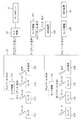
図1は、本実施形態のセンサネットワークシステムの構成の一例を示す図である。センサネットワークシステムは、各種状態の検知を行うセンサ11(複数のセンサ11A、11B、11C、11D、11E、11Fを代表する)と、センサ11からの検知情報を取得するセンサ親機15(複数のセンサ親機15A、15B、15C、15Dを代表する)とを有する。センサ11とセンサ親機15とは、無線接続され、機器間にて無線通信を行って検知情報を含むデータを送受信する。
(Whole system configuration)
FIG. 1 is a diagram illustrating an example of a configuration of a sensor network system according to the present embodiment. The sensor network system includes a sensor 11 (representing a plurality of
センサ11とセンサ親機15との間の無線通信は、例えば、DECT(Digital Enhanced Cordless Telecommunications)の無線通信方式を用いる。この場合、センサ11は、詳細は図示しないが、温度、湿度、煙、ガス、火災等の各種の状態を検知する検知部と、検知状態を表す検知情報をDECTの無線信号により送信するDECT通信部とを有する。なお、センサ11は、電波を送信する発信機を有し、センサ親機15におけるセンサ11からの送信信号の受信強度により位置を検出してセンサ11を含む物体の位置検知を行うための位置センサを含む。センサ親機15は、無線接続されたセンサ11との間の通信を制御し、各センサ11から伝送される検知情報を取得する。
The wireless communication between the
また、センサネットワークシステムは、無線通信による音声通話が可能な音声端末12(複数の音声端末12A、12Bを代表する)と、センサ11による検知情報(状態など)に応じた報知を行う報知装置13(複数の報知装置13A、13Bを代表する)とを有する。音声端末12は、詳細は図示しないが、マイクと、スピーカと、音声信号を処理するCODEC(COder/DECoder)ブロック及びDSP(Digital Signal Processor)と、音声信号をDECTの無線信号により送信するDECT通信部とを有する。音声端末12は、センサ親機15と無線接続され、機器間にて無線通信を行って構内電話用の音声信号及び各種データを送受信する。なお、音声端末12は、音声信号によって検知情報を伝送するセンサとしての機能を有する場合も含む。センサ親機15は、無線接続された音声端末12との間の通信を制御し、通信対象となる特定の音声端末12に対して音声信号を送受信し、構内電話の通話を可能にする。
In addition, the sensor network system includes a voice terminal 12 (representing a plurality of
報知装置13は、詳細は図示しないが、各種報知を行うためのスピーカ、表示デバイス(ディスプレイ又はLED表示器など)等と、報知情報を受信する通信部(DECTの無線通信部又は有線通信部)とを有する。報知装置13は、センサ親機15と無線又は有線によって接続され、機器間にて無線通信又は有線通信を行って報知情報を含むデータ、或いは音声信号を受信する。センサ親機15は、無線接続又は有線接続された報知装置13との間の通信を制御し、報知対象となる特定の報知装置13に対して報知情報又は音声信号を送信する。なお、音声端末12は、音声信号によって報知情報を受信する報知装置としての機能を有する場合も含む。報知装置13は、検知位置、検知した状態などの検知情報に対応して、報知対象と報知内容の少なくとも一方について、適応的な報知を実行する。
Although not shown in detail, the
センサ親機15は、通信線としての電力線18に接続され、電力線18を介してPLC(Power Line Communications)親機16と接続される。複数のセンサ親機15を有する場合、各センサ親機15A、15B、15C、15DとPLC親機16とが相互に電力線18を介して接続される。電力線18は、センサネットワークシステムの設置場所に設けられる各種機器又は照明装置への電力供給を行う商用電源の配線を用いればよい。なお、通信線は、電力線18の代わりに、同軸線等の配線を用いてもよい。センサ親機15とPLC親機16とは、PLCによる有線通信を行い、検知情報、報知情報等を含むデータ、及び音声信号を送受信する。センサ親機15は、DECT等による無線通信機能と、PLCによる有線通信機能とを有する。センサ親機15の構成については後述する。
The
PLC親機16は、電力線18を介して接続されたセンサ親機15との間の通信を制御し、センサ親機15から伝送されるデータを収集し、送信対象となる特定のセンサ親機15に対してデータを送信する。PLC親機16の構成については後述する。
The
PLC親機16は、データサーバ17と接続され、データサーバ17との間でデータを送受信する。PLC親機16とデータサーバ17との間の通信は、例えば、Ethernet(登録商標)、USB、RS−232C等の有線通信によって行われる。データサーバ17は、センサ11にて検知した検知情報を含むデータを、センサ親機15、PLC親機16を介して取得し、図示しないメモリ又はストレージに記憶して蓄積する。データサーバ17は、センサ11の検知情報に基づき、所定の状態になったこと、或いは異常などの所定の事象が検知されたことを判定し、対応する報知情報を含むデータを送信する。データサーバ17からの報知情報は、PLC親機16、センサ親機15を介して送信対象の報知装置13に対して伝送される。データサーバ17の構成については後述する。
The
なお、センサ11、センサ親機15、音声端末12、報知装置13は、センサネットワークシステムの設置場所に応じて、単数又は複数の所定数設ければよい。
In addition, the
(システム構成例1)
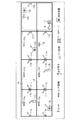
図2は、本実施形態のセンサネットワークシステムの具体的な構成例を示す図である。図2では、1階と2階の2つのフロアに設けられた複数の部屋にそれぞれセンサ11及びセンサ親機15を設け、各センサ親機15とPLC親機16とを電力線18によって接続した構成例を示している。
(System configuration example 1)
FIG. 2 is a diagram illustrating a specific configuration example of the sensor network system of the present embodiment. In FIG. 2, a configuration in which a
検知対象エリアにおいて、2階の各部屋にはセンサ11a、11b、11c、11d、11e、11f、11gが壁等に設置され、1階の各部屋にはセンサ11h、11i、11j、11k、11m、11nが壁等に設置される。センサ11a〜11nは、電池又はエナジーハーベストによって駆動電力を得て検知動作及び無線通信動作を実行するものである。なお、センサ11a〜11nは、電力線18からの商用電源など、他の外部電源により駆動するものであってもよい。また、建物内には、報知装置13a、13b、13cが適宜設置される。さらに、検知対象エリア内には、音声端末12a、12bが適宜位置している。
In the detection target area,
各部屋の天井には、センサ親機15a、15b、15c、15d、15e、15f、15gが設置される。センサ親機15a〜15gには、センサ11a〜11n、音声端末12a、12b、報知装置13a〜13cが無線接続又は有線接続される。図示例では、報知装置13bのみがセンサ親機15dと有線接続され、他はセンサ親機15a〜15gのいずれかに無線接続される構成を示したが、センサ1、音声端末、報知装置のうちのいずれかがセンサ親機と直接有線接続されていてもよい。センサ親機15a〜15gは、各部屋の天井内部に配線された電力線18に接続される。センサ親機15a〜15gは、電力線18を伝送される商用電源により駆動するものであるが、電池を内蔵し、電池を電源として駆動するものであってもよい。
監視室には、PLC親機16、データサーバ17が設置され、PLC親機16が壁内部に配線された電力線18に接続され、PLC親機16とデータサーバ17が有線接続される。PLC親機16には、センサ親機15a〜15gからのデータ又は音声信号が伝送され、PLC親機16からデータサーバ17に転送される。また、データサーバ17から送信されるデータ又は音声信号は、PLC親機16より送信対象である所定のセンサ親機に伝送される。
In the monitoring room, a
例えば、特定のセンサ11cによって異常が検知された場合、データサーバ17は、異常検知された場所に応じて予め設定された報知装置(例えば検知位置の近傍にある報知装置13a)を報知対象に決定し、報知情報を送信する。この際、検知位置に応じた報知対象エリアを決定し、報知対象エリアにある報知装置に報知情報を送信してもよい。また、データサーバ17は、検知された状態に応じて予め設定された内容の報知情報を、報知対象となる報知装置に対して送信する。なお、地震発生時などに、データサーバ17によって報知装置に対して異常報知(アラート報知)などを一斉に報知することも可能である。また、報知装置13の位置に応じて、例えば火災等の異常が発生した場合の位置に応じた避難経路の案内などを報知情報とし、報知場所に応じた報知を実行してもよい。
For example, when an abnormality is detected by a
センサ11a〜11nは、電池駆動又はエナジーハーベスト駆動とし、センサ親機15a〜15gとの間で無線通信を行うことにより、所望の場所に自由に設置可能である。センサ親機15a〜15gとPLC親機16との間でPLCによる有線通信を行うことにより、検知対象エリアにおいて床、壁等を超えた広範囲での安定した通信が可能である。また、センサネットワークシステムの機器間にて双方向通信を行うことにより、検知情報の収集だけでなく、音声通話、報知(現在の状態報知、異常発生時の異常報知など)を行う通信システムを統合できる。
The
また、センサ親機15a〜15gを電池駆動とした場合、停電時であっても一定時間動作可能である。この場合、センサ親機15a〜15gは、電力線18からの入力電圧を監視し、停電又はブレーカの遮断を検知した場合は検知信号をPLC親機16に送信する。これにより、監視室において停電状態を監視できる。PLC通信部を持つセンサ親機15a〜15gには、電力線18に供給される交流電力の電源周波数に同期したノイズを検出してノイズ低減を行うために、交流電力のゼロクロス点を検出するゼロクロス検出回路が設けられる。このゼロクロス検出回路を利用して、新たに停電検知回路を設けることなく、ゼロクロス点の不検出により停電検知が可能であり、システムの電圧監視機能を実現できる。
Further, when the
また、センサ11a〜11nとセンサ親機15a〜15gとの間で無線通信を行う場合に、複数のセンサ親機15a〜15gが相互干渉しないように、データサーバ17が都度選択したセンサ親機15に対してのみ、データ送信要求を送る。センサ親機15は、データサーバ17からのデータ送信要求を受けると、自装置の通信範囲にあるセンサ11からの信号を受信する。データサーバ17は、センサ11の位置に応じてセンサ11とセンサ親機15との対応(紐付け、ペアリング)を決定し、センサ管理テーブルによって各センサを管理する。センサ管理テーブルについては後述する。データサーバ17は、センサ管理テーブルに基づいて特定のセンサ親機15にデータ送信要求を送り、データ送信要求を受けたセンサ親機15が自装置に紐付けられているセンサ11の信号を受信する。これにより、センサ親機15a〜15g間の相互干渉を低減でき、無線通信の伝達特性を改善できる。
Further, when wireless communication is performed between the
(システム構成例2)
図3は、本実施形態のセンサネットワークシステムの具体的な他の構成例を示す図である。図3は図2の変形例であり、通信線として電力線18の代わりに同軸線19を用いた構成を示している。
(System configuration example 2)
FIG. 3 is a diagram illustrating another specific configuration example of the sensor network system according to the present embodiment. FIG. 3 is a modification of FIG. 2 and shows a configuration in which a
検知対象エリアにおいて、2階の各部屋にはセンサ11a、11b、11c、11dが壁等に設置され、1階の各部屋にはセンサ11e、11f、11gが壁等に設置される。各部屋の壁等には、センサ親機15a、15b、15c、15d、15e、15f、15gが設置され、センサ親機15a〜15gには、センサ11a〜11g、音声端末12a、12b、報知装置13a〜13cが無線接続又は有線接続される。
In the detection target area,
センサ親機15a〜15gは、各部屋の壁、床或いは天井の内部に配線された同軸線19に接続される。例えば、TV視聴用のアンテナケーブルなど、同軸線19が建物内に配線されている場合は、同軸線19を電力線18と同様に用いて、センサ親機15a〜15gとPLC親機16との間で有線通信を行うことができる。この場合、同軸線19に接続されたセンサ親機15a〜15g及びPLC親機16の電源供給は、同軸線経由でもよいし、他の電源線経由で行ってもよい。同軸線19を用いた構成においても、電力線18の場合と同様に、DECT等による無線通信とPLCによる有線通信とを利用して、センサの検知情報の収集、音声通話、検知状況に応じた報知を実行可能である。
The
(センサ親機構成例)
図4は、センサ親機15の構成例を示すブロック図である。センサ親機15は、DECT通信部21と、PLC通信部22とを有する。DECT通信部21とPLC通信部22とはレベル変換回路23を介して接続され、2つの通信部の間で相互にデータを伝送可能に構成される。センサ親機15のPLC通信部22は、電力線18に接続される。
(Sensor base unit configuration example)
FIG. 4 is a block diagram illustrating a configuration example of the
PLC通信部22は、メインIC(Integrated Circuit)26、メモリ271、ローパスフィルタ(LPF:Low Pass Filter)272、ドライバIC273、バンドパスフィルタ(BPF:Band Pass Filter)274、トランス275、及びカップリング用コンデンサ276、277を有する。
The
メインIC26は、CPU(Central Processing Unit)261、PLC・MAC(Power Line Communication - Media Access Control layer)ブロック262、PLC・PHY(Power Line Communication - Physical layer)ブロック263、及びUART(Universal Asynchronous Receiver Transmitter)ブロック264を含む。また、メインIC26は、DA変換器(DAC:Digital to Analog Converter)265、AD変換器(ADC:Analog to Digital Converter)266、及び可変増幅器(VGA:Variable Gain Amplifier)267を含む。
The
CPU261は、メモリ271に記憶されたプログラム、データを利用して、PLC・MACブロック262、及びPLC・PHYブロック263の動作を制御し、PLC通信部22の全体を制御する。PLC・MACブロック262は、送信信号及び受信信号のMAC層を管理する。PLC・PHYブロック263は、送信信号及び受信信号のPHY層を管理する。UARTブロック264は、非同期でシリアル通信を行うインタフェースであり、CPU261とDECT通信部21のプロセッサとの間でデータの送信、受信を行う。
The CPU 261 controls the operation of the PLC / MAC block 262 and the PLC / PHY block 263 by using the program and data stored in the
PLC通信部22は、送信用の回路として、PLC・PHYブロック263の出力端にDA変換器265、ローパスフィルタ272、及びドライバIC273が接続される。また、PLC通信部22は、受信用の回路として、PLC・PHYブロック263の入力端にAD変換器266、可変増幅器267、及びバンドパスフィルタ274が接続される。ドライバIC273とバンドパスフィルタ274はトランス275の一端に接続され、トランス275の他端は、カップリング用コンデンサ276、277を介して電力線18に接続される。
In the
メインIC26は、一般的なモデムと同様に、例えばデータ通信のための基本的な制御又は変復調を含む信号処理を行う電気回路(LSI:Large Scale Integration)である。例えば、メインIC26は、DECT通信部21から伝送されレベル変換回路23を介して入力されるデータを変調し、送信信号(データ)として電力線18側に出力する。また、メインIC26は、電力線18側から伝送され入力される信号を、受信信号(データ)として復調し、レベル変換回路23を介してDECT通信部21に出力する。レベル変換回路23は、接続する2つの回路間のハイレベルの電圧を変換するものである。例えばPLC通信部22のハイレベルが3.3V、DECT通信部21のハイレベルが1.8Vの場合、レベル変換回路23は、一方の回路の信号電圧を他方の回路の信号電圧と適合するようにレベル変換を行う。
The
DECT通信部21は、メインIC24、及びRF(Radio Frequency)回路25を有する。メインIC24は、無線送受信回路(RADIO TRANSIVER)241、メモリ242、CPU243、DSP(Digital Signal Processor)244、CODEC(COder/DECoder)ブロック245、SPI(Serial Peripheral Interface)ブロック246、AD変換器(ADC)247、及びUARTブロック248を含む。
The
CPU243は、メモリ242に記憶されたプログラム、データを利用して、無線送受信回路241の動作を制御し、DECT通信部21の全体を制御する。メモリ242とCPU243との間は、FIFO(First-In First-Out)処理によりデータ転送を行う。CODECブロック245は、図示しないマイク、スピーカ等の音声機器が接続可能であり、音声信号のエンコード、デコードを行う。DSP244は、エンコードされた音声データの各種処理を行う。SPIブロック246は、図示しないセンサ等のデジタル出力端が接続可能であり、入力されるデジタル信号のシリアル/パラレル変換を行う。AD変換器247は、図示しないセンサ等のアナログ出力端が接続可能であり、入力されるアナログ信号をデジタル信号に変換する。UARTブロック248は、前述したPLC通信部22のUARTブロック264と協働し、PLC通信部22のプロセッサとの間でデータの送信、受信を行う。
The
無線送受信回路241は、符号化回路、復号化回路等の信号処理回路を有し、DECTの通信方式によるベースバンド帯域の無線通信処理を実行する。RF回路25は、アンテナ、周波数変換回路、変調回路、復調回路等の無線通信回路を有し、DECTの通信方式に対応した無線周波数帯域の送信動作、受信動作を実行する。メインIC24は、無線送受信回路241にて受信され入力される受信信号(データ)を信号処理し、レベル変換回路23を介してPLC通信部22に出力する。また、メインIC24は、PLC通信部22からから伝送されレベル変換回路23を介して入力されるデータを信号処理し、送信信号(データ)として無線送受信回路241に出力し、無線送受信回路241から送信する。
The wireless transmission /
上記構成により、センサ親機15は、DECT通信部21によってセンサ11、音声端末12、報知装置13と無線通信し、センサ11からの検知情報の収集、音声端末12との間での音声信号の送受信、報知装置13への報知情報の伝送を行う。また、センサ親機15は、PLC通信部22によってPLC親機16と有線通信し、PLC親機16に接続されたデータサーバ17との間で、検知情報、音声信号、報知情報の伝送を行う。
With the above configuration, the
また、センサ親機15において、PLC通信部22と並列に、コイルを有してなるインピーダンスアッパ28が電力線18に接続され、インピーダンスアッパ28を介して外部電源用のコンセント29が設けられる。コンセント29は、天井の照明設置箇所、床面、壁面などに設けてもよい。インピーダンスアッパ28を介した外部端子であるコンセント29に照明装置、電子機器等の周辺機器の電源ラインを接続することにより、PLC通信部22から見た周辺機器のインピーダンスを高くする。これによって、電力線通信の通信信号の減衰、及び周辺機器からのノイズの影響を低減でき、電力線通信時の信号伝達特性を改善できる。
In the
(PLC親機構成例)
図5は、PLC親機16の構成例を示すブロック図である。PLC親機16は、PLCによる有線通信を行うPLC通信部を有し、電力線18に接続される。また、PLC親機16は、データサーバ17との間で有線通信を行う有線通信回路33を有し、有線通信用の接続端子34、及び図示しない通信ケーブルを介して、データサーバ17と接続される。
(PLC master unit configuration example)
FIG. 5 is a block diagram illustrating a configuration example of the
PLC親機16は、PLC通信部として、メインIC31、メモリ321、ローパスフィルタ(LPF)322、ドライバIC323、バンドパスフィルタ(BPF)324、トランス325、及びカップリング用コンデンサ326、327を有する。メインIC31は、CPU311、PLC・MACブロック312、PLC・PHYブロック313、DA変換器(DAC)315、AD変換器(ADC)316、及び可変増幅器(VGA)317を含む。PLC通信部は、図4に示したセンサ親機15のPLC通信部22と同様の構成及び機能を有するものであり、重複する部分の説明は省略する。
The
メインIC31は、電力線18側から伝送され入力される信号を、受信信号(データ)として復調し、有線通信回路33に出力する。メインIC31は、有線通信回路33から伝送されて入力されるデータを変調し、送信信号(データ)として電力線18側に出力する。有線通信回路33は、Ethernet(登録商標)、USB、RS−232C等の通信インタフェースを構成する回路であり、データサーバ17とPLC親機16との間のデータ伝送を実行する。なお、PLC親機16は、データサーバ17、監視端末などの他の装置と無線通信を行う無線通信部を有していてもよい。
The
(データサーバ構成例)
図6は、データサーバ17の構成例を示すブロック図である。データサーバ17は、ハードウェア構成としては、CPU、メモリ、ストレージ、通信インタフェース等を有してなるコンピュータにより構成される。データサーバ17は、通信回路41、演算処理部42、メモリ部43、表示回路44を有する。
(Data server configuration example)
FIG. 6 is a block diagram illustrating a configuration example of the
データサーバ17は、有線通信用の接続端子45、及び図示しない通信ケーブルを介して、PLC親機16と接続される。通信回路41は、PLC親機16の有線通信回路33と対応して、Ethernet(登録商標)、USB、RS−232C等の通信インタフェースを構成する回路であり、データサーバ17とPLC親機16との間のデータ伝送を実行する。
The
演算処理部42は、CPU、RAM(Random Access Memory)、ROM(Read Only Memory)等を有して構成され、所定のソフトウェアプログラムに従って、データサーバ17の動作に関する演算処理を実行する。メモリ部43は、フラッシュメモリ、ハードディスクドライブ等によるストレージを有して構成され、センサネットワークシステムにおける各種データを記憶し、蓄積する。メモリ部43には、詳細は後述するが、検知対象エリア内のセンサ11を管理する管理データを格納したセンサ管理テーブル、音声端末12、報知装置13等の機器を管理する管理データを格納した機器管理テーブル等が記憶される。
The
また、データサーバ17は、映像出力用の接続端子46、及び図示しない映像ケーブルを介して、LCD(Liquid Crystal Display)又は有機EL(Electroluminescence)を用いて構成される表示モニタとしてのディスプレイと接続される。表示回路44は、演算処理部42から出力される表示データを信号処理して画面表示用の映像信号を生成し、ディスプレイに対して出力する。ディスプレイには、センサ管理テーブル、センサの配置状況、報知装置への報知内容など、検知情報の収集及び通知情報の配信に関する各種情報を表示する。
Further, the
(システム動作概要説明)
図7は、本実施形態のセンサネットワークシステムにおけるデータの流れを説明する図であり、図7(A)はセンサデータ収集時の動作を示す図、図7(B)はアラート通知時の動作を示す図、図7(C)は音声通話時の動作を示す図である。
(System operation overview explanation)
7A and 7B are diagrams for explaining the flow of data in the sensor network system according to the present embodiment. FIG. 7A shows an operation at the time of collecting sensor data, and FIG. 7B shows an operation at the time of alert notification. FIG. 7C is a diagram showing an operation during a voice call.
図7(A)に示すように、センサデータを収集する場合は、検知情報のデータがセンサ11からデータサーバ17に伝送される。この場合、センサ11は、温度、湿度、煙、ガス、火災等の各種の状態の検知情報を、各センサ11が紐付けられた(ペアリングされた)センサ親機15に対して送信する。センサ親機15は、自装置に登録されたセンサ11からの検知情報を受けると、PLC親機16に伝送する。PLC親機16は、センサ親機15から検知情報を受信し、データサーバ17に転送する。これにより、センサ11において検知した検知情報がデータサーバ17に収集され、保存される。
As shown in FIG. 7A, when sensor data is collected, data of detection information is transmitted from the
データサーバ17は、収集した検知情報に基づいて検知対象エリア内の各部の状態を判定し、通常状態又は異常状態の報知に関する報知情報を報知装置に送信して報知を行わせる。図7(B)に示すように、アラート通知を行う場合は、アラート通知用の報知情報のデータ又は音声信号がデータサーバ17から報知装置13に伝送される。この場合、データサーバ17は、異常状態のアラート通知を行う所定の条件を満たす場合に、アラート報知用の報知情報のデータ又は音声信号をPLC親機16に送信する。PLC親機16は、データサーバ17から報知情報を受信し、報知対象となる報知装置13を紐付けているセンサ親機15に対して伝送する。センサ親機15は、自装置に登録された報知装置13への報知情報を受けると、該当の報知装置13に伝送する。これにより、検知情報に応じて報知対象の報知装置13にアラート通知の報知情報が伝送され、アラート通知が行われる。
The
図7(C)に示すように、音声通話を行う場合は、複数の音声端末12A、12Bの間で音声信号が双方向に伝送される。ここでは一方向の信号伝送についてのみ説明する。音声端末12Aは、自装置が紐付けられた(ペアリングされた)センサ親機15Aに対して、通話用の音声信号を送信する。センサ親機15Aは、PLC親機16を経由してデータサーバ17に音声信号を伝送する。また、データサーバ17は、PLC親機16を経由して通話相手の音声端末12Bが紐付けられたセンサ親機15Bに音声信号を送信する。センサ親機15Bは、自装置に登録された音声端末12Bへの音声信号を受けると、該当の音声端末12Bに伝送する。これにより、複数の音声端末12A、12Bの間で音声信号が送受信され、音声通話が行われる。この場合、データサーバ17は、構内電話に関する呼制御等の処理を実行する。
As shown in FIG. 7C, when a voice call is performed, a voice signal is transmitted bidirectionally between the plurality of
(検知情報収集及び報知情報送信の処理例)
図8は、本実施形態におけるセンサデータ収集及びアラート通知に関する処理を示すフローチャートである。センサ親機15は、自装置に登録された各センサ11による検知情報のデータ、及び各センサ11から伝送される信号の受信強度を取得する(ステップS11)。そして、センサ親機15は、取得した検知情報のデータをPLC親機16を経由してデータサーバ17へ送信する(ステップS12)。データサーバ17は、各センサ11から取得した検知情報のデータの解析を行い、取得データを保存する(ステップS13)。
(Example of detection information collection and notification information transmission)
FIG. 8 is a flowchart showing processing relating to sensor data collection and alert notification in the present embodiment. The
そして、データサーバ17は、取得データの解析結果に基づき、アラート通知を行う所定の条件を満たすかを判定し、アラート発信が必要であるかどうかの判定を行う(ステップS14)。ここで、アラート発信が必要であると判定した場合、データサーバ17は、アラート通知対象、及びアラート通知内容を決定する(ステップS15)。そして、データサーバ17は、アラート通知対象へアラート発信を行い、アラート通知の報知情報をPLC親機16、センサ親機15を経由してアラート通知対象の報知装置13に送信する(ステップS16)。
Then, the
アラート発信が必要な場合としては、所定箇所の火災報知機が鳴った、非常ボタンが押された、ガスが検知された、温度が異常に高くなった、検知対象の人、物があるべき場所にない(異常な場所にある)、などがある。また、アラート発信が不要な場合としては、例えば、所定箇所の温度異常なし、検知対象の人、物が正常な場所にある、などがある。 When alert transmission is necessary, a fire alarm at a predetermined location sounds, an emergency button is pressed, gas is detected, the temperature is abnormally high, the person to be detected, the place where there should be Is not (in an abnormal place). In addition, examples of cases where alert transmission is unnecessary include, for example, that there is no temperature abnormality at a predetermined location, the person to be detected, or an object is in a normal location.
報知装置13に送信するアラート通知の態様としては、表示データ、鳴動データ等のデータ、或いは音声信号などを用いる。表示データとしては、対象者に知らせる異常内容を表す文字や画像、検知位置や異常内容に対応した避難経路の画像、などがある。
As an alert notification mode to be transmitted to the
なお、検知情報に応じてアラート通知などの報知を行う際に、センサ11からの検知情報だけでなく、音声端末12からの報告者による異常報告の音声信号を検知情報として用い、報知を行うことも可能である。この場合、異常を発見した報告者が音声端末12を用いて構内電話の通話にて監視室の監視端末(例えば図12に示す監視端末48)に発信し、異常報告を行う。音声端末12には、緊急通知ボタンなどを設けて緊急通話を可能にしてもよい。監視者は、監視室に設けた監視端末によって音声端末12からの音声信号の通知を受けると、どの場所にどんな内容のアラート通知を行うか、手動で選択して設定し、監視端末のアラート発報ボタンを操作してアラート通知を発信する。監視端末は、例えばPC(Personal Computer)を用いて構成され、データサーバ17の表示端末及び操作端末として機能し、データサーバ17に記憶される検知情報及び報知情報の確認、センサ等の機器の管理、アラート通知の指示等が可能になっている。
In addition, when performing notification such as alert notification according to detection information, notification is performed using not only detection information from the
図9は、監視端末の表示部に表示されるアラート発信画面の一例を示す図である。監視端末のアラート発信画面51には、検知対象エリアのレイアウト表示52が設けられる。レイアウト表示52には、センサ11により異常が検知されたセンサ反応エリア53、センサ反応エリア53に対応して自動又は手動で設定されるアラート通知エリア54が所定のマーク、色、模様などによって示される。図示例では、センサ反応エリア53をドット模様、アラート通知エリア54を格子模様にて示している。この例は、2階の左端の部屋において危険物が漏れてセンサによって検知され、隣の部屋にいる報告者が音声端末によって監視室に異常を報告した場合を示している。監視者は、監視端末のタッチスクリーン等によってセンサ反応エリア53の周囲をアラート通知エリア54として選択して設定し、アラート発報ボタン55をタッチ操作してアラート通知を指示する。監視者の指示操作に従って、データサーバ17は、アラート通知エリア54にある報知装置に対して報知情報を送信し、アラート通知を実行する。
FIG. 9 is a diagram illustrating an example of an alert transmission screen displayed on the display unit of the monitoring terminal. On the
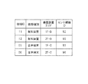
ここで、データサーバ17において管理するセンサ11、音声端末12、報知装置13等の管理テーブルの具体例について説明する。図10は、センサ11を管理する管理データを格納したセンサ管理テーブルの例を示す図である。図11は、音声端末12、報知装置13等の機器を管理する管理データを格納した機器管理テーブルの例を示す図である。
Here, a specific example of the management table of the
データサーバ17は、センサ管理テーブルと、機器管理テーブルとを有し、検知対象エリア内にて無線通信するセンサ及び機器を管理する。なお、一つの管理テーブルによってセンサ及び他の機器を管理するようにしてもよい。
The
センサ管理テーブルは、センサID、センサ種別、センサ設置エリア、センサ親機ID、センサ反応時通知エリア、通知内容、を有する。データサーバ17は、センサID毎に、各センサの状態を管理し、対応する動作を設定する。センサIDは、各センサに個別に割り振られる。センサ種別は、火災センサ、非常ボタンなどの種別を表す。
The sensor management table includes a sensor ID, a sensor type, a sensor installation area, a sensor parent device ID, a sensor reaction notification area, and notification contents. The
センサ親機IDは、当該センサに紐付けられている(ペアリングされている)センサ親機のIDを表す。それぞれのセンサ11は、周囲のセンサ親機15と無線通信を行い、データサーバ17が、検知情報を通信するセンサ11とセンサ親機15とのペアリングを決定する。センサ11から送信される検知情報を含むデータは、ペアリングされたセンサ親機15にて受信され、PLC親機16に伝送される。
The sensor base unit ID represents the ID of the sensor base unit linked (paired) to the sensor. Each
センサ親機ID及びセンサ設置エリアは、それぞれのセンサ親機15からデータサーバ17に送信される各センサの情報に基づいてデータサーバ17が決定する。センサ11が移動して設置場所が変更になった場合、データサーバ17は、各センサ親機15からのセンサの情報に基づき、センサ親機ID及びセンサ設置エリアを変更して再設定し、センサ管理テーブルを更新する。
The
センサ設置エリアの決定方法としては、例えば以下の方法が挙げられる。第1の方法は、データサーバ17にて取得される、各センサ親機15におけるセンサ11の受信信号の受信強度の中で最も強いセンサ親機15があるエリアを、当該センサ11のセンサ設置エリアと判断するものである。第2の方法は、データサーバ17にて取得される、各センサ親機15におけるセンサ11の受信信号の受信強度のうち、強い方から3つのセンサ親機15を抽出し、3点のセンサ親機15の位置から三点測位を行って当該センサ11のセンサ設置エリアを推定するものである。第3の方法は、各センサ11の配置場所から、予め固定的にセンサ11とセンサ親機15のペアリングを設定し、当該センサ11が特定のセンサ親機15と無線通信するようにしたものである。
Examples of the method for determining the sensor installation area include the following methods. In the first method, the area where the
センサ反応時通知エリアは、報知対象エリアに相当し、当該センサが反応して異常等が検知された場合に、アラート通知を行うアラート通知エリアを表す。例えば、1F−Aのエリアに設置されたセンサID02の火災センサにより火災が検知された場合は、センサ親機ID91のセンサ親機を介してデータサーバ17に検知情報が伝送される。この場合、アラート通知エリアとして、1F−A,B,Cと2F−Aが設定されており、このエリアにある報知装置に報知情報が送信される。
The sensor reaction time notification area corresponds to a notification target area, and represents an alert notification area for performing alert notification when the sensor reacts and an abnormality or the like is detected. For example, when a fire is detected by the fire sensor with
センサ11が移動してセンサ設置エリアが変更になると、データサーバ17は、センサのエリア変更に伴ってセンサ反応時通知エリアを変更して再設定し、センサ管理テーブルを更新する。
When the
通知内容は、アラート通知する際の内容を表す。例えば、上記の1F−Aのエリアの火災検知の場合、「1F−Aで火災反応 至急現場確認せよ」のアラート通知が1F−A,B,Cと2F−Aにある報知装置に送信され、文字表示、音等によるアラート通知が実行される。 The notification content represents the content at the time of alert notification. For example, in the case of fire detection in the above-mentioned 1F-A area, an alert notification “1F-A fire reaction urgently check the site” is sent to the notification devices in 1F-A, B, C and 2F-A, Alert notification is executed by character display, sound or the like.
機器管理テーブルは、機器ID、機器種別、機器設置エリア、センサ親機ID、を有する。データサーバ17は、機器ID毎に、報知装置13等の各機器の状態を管理し、対応する動作を設定する。機器IDは、各機器に個別に割り振られる。機器種別は、報知装置、音声端末などの種別を表す。センサ親機IDは、当該機器に紐付けられている(ペアリングされている)センサ親機のIDを表す。報知装置13等のそれぞれの機器は、センサ11と同様に、周囲のセンサ親機15と無線通信を行い、データ等を送受信する相手のセンサ親機15とペアリングされる。
The device management table has a device ID, a device type, a device installation area, and a sensor master device ID. The
なお、図示例では、音声端末は、センサとしての機能を有するため、センサ管理テーブルと機器管理テーブルの両方に管理情報を有するように示しているが、センサ管理テーブルのみで管理するようにしてもよい。 In the illustrated example, since the voice terminal has a function as a sensor, both the sensor management table and the device management table are shown to have management information. However, the voice terminal may be managed only by the sensor management table. Good.
(ユースケースの具体例)
次に、本実施形態のセンサネットワークシステムのユースケースをいくつか例示する。
(Specific examples of use cases)
Next, some use cases of the sensor network system of this embodiment will be exemplified.
図12は、第1のユースケースのシステム構成及び動作を説明する図である。第1のユースケースは、可燃性ガスなどの引火性のある危険物の漏れをセンサにより監視する危険物管理システムの例である。 FIG. 12 is a diagram illustrating the system configuration and operation of the first use case. The first use case is an example of a dangerous goods management system that monitors the leakage of flammable dangerous goods such as flammable gas with a sensor.
検知対象エリアにおいて、2階の左端の部屋にセンサ11aが壁に設置され、室内に危険物61が置かれている。また、1階の左端の部屋にセンサ11bが壁に設置され、室内に危険物61が配置されている。危険物としては、ガス管、化学薬品庫、水素ステーションなどが想定される。2階の左から2番目の部屋には音声端末12aを持った作業者71aが、また、1階の右から2番目の部屋には音声端末12bを持った作業者71bが、さらに、2階の右端の部屋には音声端末12cを持った作業者71cが、それぞれ存在している。
In the detection target area, a
各部屋の天井には、センサ親機15a、15b、15c、15d、15e、15f、15gが設置される。センサ親機15a〜15gには、センサ11a、11b、音声端末12a〜12cが無線接続される。センサ親機15a〜15gは、各部屋の天井内部に配線された電力線18に接続され、電力線18を介してPLC親機16と接続される。
監視室には、PLC親機16、データサーバ17が設置され、PLC親機16が壁内部に配線された電力線18に接続され、PLC親機16とデータサーバ17が有線接続される。データサーバ17には、ディスプレイを有する監視端末48が接続される。監視室にいる監視者72は、監視端末48を目視で監視し、異常が検知された場合、端末操作によってアラート通知等を行う。
In the monitoring room, a
この場合、センサ11a、11bによってガス漏れなどの異常を検知すると、データサーバ17は、センサ11a、11bからの検知情報に基づき、作業者71a〜71cが持っている音声端末12a〜12cに対して音声信号によるアラート通知を送信する。例えば、検知位置及び検知対象の状態に応じて、現場の状況確認要求、避難指示などを各音声端末12a〜12cに対して適応的に報知できる。ここで、異常を検知したセンサの位置に応じて、近くにいる音声端末のみにアラート通知を送信してもよい。例えば、2階のセンサ11aが異常検知した場合は2階の一番近くにある音声端末12aにアラート通知を行い、1階のセンサ11bが異常検知した場合は1階にある音声端末12bにアラート通知を行う。作業者71a〜71cは、アラート通知を受けて、音声端末12a〜12c間で通話を行って連絡を取り合い、連携して異常発生に対処することができる。本例によれば、異常検知位置に応じたアラート通知が実行可能である。
In this case, when an abnormality such as a gas leak is detected by the
図13は、第2のユースケースのシステム構成及び動作を説明する図である。第2のユースケースは、火災の発生をセンサ又は非常ボタン装置の操作によって検知し、避難誘導を行う避難誘導システムの例である。 FIG. 13 is a diagram for explaining the system configuration and operation of the second use case. The second use case is an example of an evacuation guidance system that detects the occurrence of a fire by operating a sensor or an emergency button device and performs evacuation guidance.
検知対象エリアにおいて、2階にはセンサ11a、11b、11c、11d、11e、11f、11gが天井に設置され、1階にはセンサ11h、11i、11j、11k、11mが天井に設置される。また、2階には非常ボタン装置62a、62bと報知装置13a、13bが、1階には非常ボタン装置62c、62dと報知装置13c、13dがそれぞれ壁に設置される。さらに、2階には誘導灯63aが、1階には誘導灯63bがそれぞれ室内の上部に設置される。
In the detection target area,
各部屋の天井には、センサ親機15a、15b、15c、15d、15e、15f、15gが設置される。センサ親機15a〜15gには、センサ11a〜11m、非常ボタン装置62a〜62d、報知装置13a〜13dが無線接続され、誘導灯63aがセンサ親機15cに、誘導灯63bがセンサ親機15gにそれぞれ有線接続される。センサ親機15a〜15gは、各部屋の天井内部に配線された電力線18に接続され、電力線18を介してPLC親機16と接続される。監視室には、PLC親機16、データサーバ17が設置され、PLC親機16が壁内部に配線された電力線18に接続され、PLC親機16とデータサーバ17が有線接続される。
この場合、炎センサなどのセンサ11又は非常ボタン装置62の操作によって火災を検知すると、データサーバ17は、センサ11a〜11m又は非常ボタン装置62a〜62dからの検知情報に基づき、報知装置13a〜13dに対してアラート通知を送信し、誘導灯63a、63bに対して点灯指示を送信する。ここで、火災を検知したセンサの位置に応じて、誘導灯63a、63bの点灯パターンを制御し、火災発生場所及び避難経路等の報知内容を決定して報知装置13a〜13dに避難放送データを送信する。また、誘導灯63a、63bの近くにある報知装置13b、13dに対しては、どちらへ避難するかの音声を含む避難情報を送信して、避難する人に対する音声ガイドを行う。音声ガイドを用いることにより、障がいを持った人への対応、及び煙が充満して誘導灯が見えない場合の補助手段としての対応が可能である。火災発生場所に応じたアラート通知及び避難誘導を行うには、データサーバ17は、図10に示したセンサ管理テーブルを用いて、アラート通知エリア及び通知内容を決定し、アラート通知処理と誘導灯点灯処理を実行すればよい。
In this case, when a fire is detected by operating the
図14は、第2のユースケースにおける避難誘導の具体例を示す図である。例えば、通路がT字路に分岐しており、通路の分岐点の手前から見て左側で火災が検知された場合、センサ11aから火災検知の検知情報が送信され、センサ親機15aを経由してデータサーバ17に伝送される。データサーバ17は、火災発生場所及び避難経路を知らせる音声情報を生成して報知装置13に送信し、報知装置13から避難者に対して音声によるアラート通知を行う。また、データサーバ17は、通路の分岐点の近傍にある誘導灯63に対して、右方向への矢印を点灯させる点灯制御信号を送信し、火災発生場所に近づかないように、分岐点から火災発生場所とは反対の右側の方向への誘導経路を指示する。本例によれば、火災発生検知位置に応じたアラート通知及び避難誘導が可能となる。
FIG. 14 is a diagram illustrating a specific example of evacuation guidance in the second use case. For example, when a passage is branched into a T-junction and a fire is detected on the left side when viewed from the front of the passage branch point, detection information of fire detection is transmitted from the
なお、本例の避難誘導システムは、コンサートホールやスタジアム等の施設において観客の入退場の際の進行方向を案内する入退場誘導システムとして適用可能である。この場合、例えば観客が所持しているスマートフォン等の移動通信端末をセンサとして利用し、データサーバ17は、施設内の各エリア毎に無線LAN(Local Area Network)接続されている移動通信端末の数を検知し、観客の数、密集しているエリア、密集度合いを推定する。そして、データサーバ17は、スムーズな入退場が可能なように、エリア毎に音声又は画像による案内情報を送信し、観客の進行方向を指示する。
Note that the evacuation guidance system of this example can be applied as an entrance / exit guidance system that guides the direction of travel when a spectator enters / exits a facility such as a concert hall or a stadium. In this case, for example, a mobile communication terminal such as a smartphone possessed by a spectator is used as a sensor, and the
図15は、第3のユースケースのシステム構成及び動作を説明する図である。第3のユースケースは、人や物の位置をセンサによって検知し、所在管理を行う所在管理システムの例である。 FIG. 15 is a diagram for explaining the system configuration and operation of the third use case. The third use case is an example of a location management system that detects the position of a person or an object with a sensor and performs location management.
検知対象エリアにおいて、検知対象となる人物及び物には、RFIDタグ等によるセンサ11a、11b、11d、11e、11fがそれぞれ装着されている。図示例では、2階にいる作業者73にセンサ11aが装着されており、製品や部品を搭載した搬送車65にセンサ11b〜11fが装着されている。また、1階にいる管理者74は、音声端末12aを所持しており、監視室の監視者等と通話が可能になっている。また、各フロアには、監視カメラ64a、64bが設置される。
In the detection target area,
各フロアの天井には、センサ親機15a、15b、15c、15d、15e、15f、15gが設置される。センサ親機15a〜15gには、センサ11a〜11f、音声端末12aが無線接続される。センサ親機15a〜15gは、各部屋の天井内部に配線された電力線18に接続され、電力線18を介してPLC親機16と接続される。監視室には、PLC親機16、データサーバ17が設置され、PLC親機16が壁内部に配線された電力線18に接続され、PLC親機16とデータサーバ17が有線接続される。データサーバ17には、ディスプレイを有する監視端末48が接続される。監視室にいる監視者72は、監視端末48を目視で監視し、異常が検知された場合、端末操作によって管理者74の音声端末12aに対して報知を行う。
センサ親機15a〜15gは、RFID(Radio Frequency Identification)タグ等によるセンサ11a〜11fからの無線電波を受信し、受信信号の受信強度を取得する。データサーバ17は、センサ親機15a〜15gによるセンサ11a〜11fの検知情報に基づき、この場合は複数のセンサ親機において取得したセンサ信号の受信強度によって、各センサの位置を推定する。これにより、検知対象エリア内の検知対象の人や物がどこにあるか、あるべき位置にあるか、進入禁止エリアに入っていないか、などを把握できる。
The
また、センサ11a〜11fによる検知情報と監視カメラ64a、64bによって撮像した監視画像とを組み合わせることも可能である。例えば、監視者72は、センサ11a〜11fにより検知した検知対象の人や物の位置と、監視カメラ64a、64bにより撮像した所定エリアの撮像画像とを比較し、センサの位置と撮像された検知対象の実際の位置とが一致しているかどうかを確認する。これにより、例えばセンサが検知対象から取り外された場合などの異常を検知できる。
It is also possible to combine detection information from the
第3のユースケースは、以下のようなシステムに適用可能である。例えば、工場などでは、作業者が担当エリアに正しく位置しているか、担当エリア外に行っていないかを監視する場合に適用できる。また、搬送車やコンテナ等の所在管理に適用できる。或いは、高齢者施設又は病院では、高齢者又は患者の居場所を把握する所在管理に適用できる。また、車椅子、検査機などの備品や機器の場所を把握する所在管理に適用できる。 The third use case is applicable to the following system. For example, in a factory or the like, the present invention can be applied to monitoring whether an operator is correctly located in a responsible area or not going out of the responsible area. It can also be applied to location management of transport vehicles, containers, and the like. Or in an elderly person facility or a hospital, it can apply to the location management which grasps the whereabouts of an elderly person or a patient. Moreover, it can be applied to location management for grasping the location of equipment and equipment such as wheelchairs and inspection machines.
以上説明したように、本実施形態では、センサ−センサ親機−データサーバ−センサ親機−報知装置の間のデータ伝送において、DECT等を用いた無線通信と電力線通信を用いた有線通信とを併用し、センサによる検知情報の収集と検知情報に応じた報知情報の送信とを行う。これにより、例えば異常発生時に、異常を検知した位置、検知内容に応じて、アラート通知の報知内容、報知対象の発信先を変更可能なネットワークを簡易に構築できる。 As described above, in this embodiment, in data transmission between the sensor, the sensor master unit, the data server, the sensor master unit, and the notification device, wireless communication using DECT and wired communication using power line communication are performed. In combination, collection of detection information by the sensor and transmission of notification information according to the detection information are performed. Thereby, for example, when an abnormality occurs, a network capable of changing the notification content of the alert notification and the transmission destination of the notification target according to the detected position and the detected content can be easily constructed.
センサとセンサ親機の間にDECT等の無線通信を用い、センサ親機とデータサーバの間に電力線通信を用いることにより、レイアウトフリーのセンサネットワークシステムを構築でき、自由な配置変更に柔軟に対応できる。センサは、無線通信によってセンサ親機に検知情報を送信するため、所望の場所に容易に設置可能である。DECTの通信方式を用いた場合、音声信号とデータの双方を伝送可能であり、無線LAN等の他の通信方式との干渉が少なく、通信エリアが大きいため、安定した無線通信が可能である。また、電力線通信を用いた場合、既設の電力線の配線を利用した通信が可能であり、電力線が敷設された場所であれば所望の場所に容易にセンサ親機を設置可能である。電力線通信では、壁、床を越えた通信についても安定して実行でき、大型施設などの広い検知対象エリアに適応できる。 By using wireless communication such as DECT between the sensor and the sensor base unit, and using power line communication between the sensor base unit and the data server, a layout-free sensor network system can be constructed, and flexible layout changes can be handled flexibly. it can. Since the sensor transmits detection information to the sensor base unit by wireless communication, it can be easily installed at a desired location. When the DECT communication method is used, both voice signals and data can be transmitted, there is little interference with other communication methods such as a wireless LAN, and the communication area is large, so that stable wireless communication is possible. In addition, when power line communication is used, communication using existing power line wiring is possible, and the sensor base unit can be easily installed at a desired location where the power line is laid. In power line communication, communication across walls and floors can be performed stably, and it can be applied to large detection areas such as large facilities.
また、センサの位置が変更になった場合は、データサーバにおいてセンサ管理テーブルを更新し、センサとセンサ親機とのペアリングを適宜変更できる。また、音声端末、報知装置等が移動する場合も、同様にセンサ親機とのペアリングを更新できる。このため、配置変更後のセンサの状態検知、及び、音声端末又は報知装置へのアラート通知等の報知に容易に適応できる。 Further, when the position of the sensor is changed, the sensor management table is updated in the data server, and the pairing between the sensor and the sensor parent device can be appropriately changed. In addition, when the voice terminal, the notification device, and the like move, pairing with the sensor parent device can be similarly updated. For this reason, it is easily adaptable to notifications such as sensor state detection after arrangement change and alert notification to a voice terminal or notification device.
したがって、本実施形態によれば、どのような検知対象の配置にも柔軟に対応して簡易にシステムを構築でき、安定的に検知情報の取得が可能なセンサネットワークシステムを実現できる。また、センサの検知位置、検知内容等に応じて、適応的な報知が可能なセンサネットワークシステムを簡易に構築できる。 Therefore, according to this embodiment, a sensor network system that can flexibly cope with any detection target arrangement and can easily construct a system and can stably acquire detection information can be realized. In addition, a sensor network system capable of adaptive notification can be easily constructed according to the detection position of the sensor, the detection content, and the like.
本実施形態のセンサネットワークシステムは、センサ11による検知情報を受信するセンサ親機15と、センサ親機15からの検知情報を取得するデータサーバ17と、データサーバ17からの報知情報を受信して報知を行う報知装置13と、を有する。センサ親機15は、無線通信によってセンサ11と接続され、センサ親機15とデータサーバ17とは、電力線通信を含む有線通信によって接続され、データサーバ17と報知装置13とは、センサ親機15を経由して少なくとも一部の通信経路が電力線通信を含む有線通信によって接続されるものであり、データサーバ17は、取得した検知情報に基づき、報知対象と報知内容の少なくとも一方について、検知情報に対応した報知を実行する。
The sensor network system according to the present embodiment receives the detection information from the
これにより、配置自由度の高い無線通信と電力線通信とを組み合わせたシステム構成によって、どのような検知対象の配置にも柔軟に対応して簡易にシステムを構築でき、安定的に検知情報の取得が可能なセンサネットワークシステムを実現できる。また、センサの検知位置、検知内容等の検知情報に応じて、適応的な報知が可能なシステムを簡易に構築できる。 As a result, a system configuration that combines wireless communication and power line communication with a high degree of freedom of placement enables a system to be constructed flexibly for any kind of detection target placement, and detection information can be stably acquired. A possible sensor network system can be realized. In addition, a system capable of adaptive notification can be easily constructed according to detection information such as the detection position of the sensor and the detection content.
また、本実施形態のセンサネットワークシステムにおいて、複数のセンサ親機15を異なる位置に有し、データサーバ17は、センサ11にて検知した検知情報の検知位置を取得し、検知位置に対応した報知内容の報知を実行するものでもよい。
Further, in the sensor network system of the present embodiment, the plurality of
これにより、検知位置に応じて、例えば火災等の異常の発生場所を通知するなど、適切な報知を実行できる。 Thereby, according to a detection position, appropriate alerting | reporting, such as notifying the occurrence location of abnormality, such as a fire, can be performed, for example.
また、上記のセンサネットワークシステムにおいて、さらに、複数の報知装置13を異なる位置に有し、データサーバ17は、検知情報の検知位置に応じて報知対象の報知装置13を決定し、報知対象の報知装置13に対して報知を実行するものでもよい。
Further, in the sensor network system described above, a plurality of
これにより、検知位置に応じて、例えば検知位置の近傍、周辺など、適切な位置にある報知装置を報知対象として決定し、報知を実行できる。 Thus, according to the detection position, for example, a notification device at an appropriate position such as the vicinity of the detection position or the vicinity thereof can be determined as a notification target, and notification can be executed.
また、本実施形態のセンサネットワークシステムにおいて、複数の報知装置13を異なる位置に有し、データサーバ17は、報知装置13の位置に対応した報知内容の報知を実行するものでもよい。
Further, in the sensor network system of the present embodiment, a plurality of
これにより、報知装置の位置に応じて、例えば火災等の異常が発生した場合の位置に応じた避難経路の案内など、適切な報知を実行できる。 Thereby, according to the position of the notification device, for example, appropriate notification such as guidance of an evacuation route according to the position when an abnormality such as a fire occurs can be executed.
また、上記のセンサネットワークシステムにおいて、さらに、複数のセンサ親機15を異なる位置に有し、データサーバ17は、検知情報の検知位置を取得し、検知位置に応じて報知対象の報知装置を決定し、報知対象の報知装置に対して報知を実行するものでもよい。
Further, in the sensor network system described above, the plurality of
これにより、検知位置に応じて、例えば検知位置の近傍、周辺など、適切な位置にある報知装置を報知対象として決定し、報知を実行できる。 Thus, according to the detection position, for example, a notification device at an appropriate position such as the vicinity of the detection position or the vicinity thereof can be determined as a notification target, and notification can be executed.
以上、図面を参照しながら各種の実施形態について説明したが、本発明はかかる例に限定されないことは言うまでもない。当業者であれば、特許請求の範囲に記載された範疇内において、各種の変更例又は修正例に想到し得ることは明らかであり、それらについても当然に本発明の技術的範囲に属するものと了解される。 While various embodiments have been described above with reference to the drawings, it goes without saying that the present invention is not limited to such examples. It will be apparent to those skilled in the art that various changes and modifications can be made within the scope of the claims, and these are naturally within the technical scope of the present invention. Understood.
本発明は、どのような検知対象の配置にも柔軟に対応して簡易にシステムを構築でき、安定的に検知情報の取得が可能なセンサネットワークシステム、センサの検知位置、検知内容等に応じて、適応的な報知が可能なシステムを簡易に構築できるセンサネットワークシステムとして有用である。 The present invention flexibly adapts to the arrangement of any detection target, can easily construct a system, and can stably acquire detection information, according to sensor detection positions, detection contents, etc. It is useful as a sensor network system that can easily construct a system capable of adaptive notification.
11、11A〜11F、11a〜11m センサ
12、12A、12B、12a〜12c 音声端末
13、13A、13B、13a〜13d 報知装置
15、15A〜15D、15a〜15g センサ親機
16 PLC親機
17 データサーバ
18 電力線
21 DECT通信部
22 PLC通信部
48 監視端末
51 アラート発信画面
62a〜62d 非常ボタン装置
63、63a、63b 誘導灯
64a、64b 監視カメラ
11, 11A to 11F, 11a to
Claims (12)
前記センサ親機を経由して前記検知情報を取得するデータサーバと、
前記データサーバからの報知情報を受信して報知を行う報知装置と、を有し、
前記センサ親機は、無線通信によって前記センサと接続され、
前記センサ親機と前記データサーバとは、電力線通信を含む有線通信によって接続され、
前記データサーバと前記報知装置とは、前記センサ親機を経由して少なくとも一部の通信経路が電力線通信を含む有線通信によって接続されるものであり、
前記データサーバは、前記取得した検知情報に基づき、報知対象と報知内容の少なくとも一方について、検知情報に対応した報知を実行する、
センサネットワークシステム。 A sensor master that receives detection information from the sensor;
A data server for obtaining the detection information via the sensor base unit;
A notification device that receives notification information from the data server and performs notification, and
It said sensor base unit is connected to the sensors by wireless communication,
The sensor base unit and the data server are connected by wired communication including power line communication,
The data server and the notification device are connected by wired communication including power line communication through at least a part of the communication path via the sensor master unit,
The data server executes notification corresponding to the detection information for at least one of the notification target and the notification content based on the acquired detection information.
Sensor network system.
複数の前記センサ親機を異なる位置に有し、
前記データサーバは、前記検知情報の検知位置を取得し、前記検知位置に対応した報知内容の報知を実行する、センサネットワークシステム。 The sensor network system according to claim 1,
Having a plurality of the sensor base units at different positions;
The sensor network system, wherein the data server acquires a detection position of the detection information and performs notification of notification contents corresponding to the detection position.
複数の前記報知装置を異なる位置に有し、
前記データサーバは、前記検知情報の検知位置に応じて報知対象の報知装置を決定し、前記報知対象の報知装置に対して報知を実行する、センサネットワークシステム。 The sensor network system according to claim 2,
A plurality of the notification devices at different positions;
The said data server is a sensor network system which determines the alerting | reporting apparatus of notification object according to the detection position of the said detection information, and performs alerting | reporting with respect to the said alerting | reporting apparatus.
複数の前記報知装置を異なる位置に有し、
前記データサーバは、前記報知装置の位置に対応した報知内容の報知を実行する、センサネットワークシステム。 The sensor network system according to claim 1,
A plurality of the notification devices at different positions;
The said data server is a sensor network system which performs alerting | reporting of the alerting | reporting content corresponding to the position of the said alerting | reporting apparatus.
複数の前記センサ親機を異なる位置に有し、
前記データサーバは、前記検知情報の検知位置を取得し、前記検知位置に応じて報知対象の報知装置を決定し、前記報知対象の報知装置に対して報知を実行する、センサネットワークシステム。 The sensor network system according to claim 4,
Having a plurality of the sensor base units at different positions;
The sensor network system, wherein the data server acquires a detection position of the detection information, determines a notification device to be notified according to the detection position, and performs notification to the notification device to be notified.
複数の前記センサ親機を異なる位置に有し、Having a plurality of the sensor base units at different positions;
複数の前記報知装置を異なる位置に有し、A plurality of the notification devices at different positions;
前記データサーバは、The data server is
前記センサから取得した検知情報に基づき前記報知が必要であるかどうかの判定を行い、Determine whether the notification is necessary based on detection information acquired from the sensor,
前記報知が必要であると判定した場合は、前記必要であると判定した検知情報に対応する報知情報を、前記報知が必要であると判定した検知情報を検知したセンサと接続される第1のセンサ親機を経由して、前記第1のセンサ親機と接続する第1の報知装置に送信し、前記必要であると判定した検知情報に対応した報知を実行する、When it is determined that the notification is necessary, notification information corresponding to the detection information determined to be necessary is connected to a sensor that has detected the detection information determined to be necessary for the notification. Transmitting to the first notification device connected to the first sensor parent device via the sensor parent device, and executing notification corresponding to the detection information determined to be necessary;
センサネットワークシステム。Sensor network system.
複数の前記センサ親機を異なる位置に有し、Having a plurality of the sensor base units at different positions;
複数の前記報知装置を異なる位置に有し、A plurality of the notification devices at different positions;
検知対象エリアに設けた前記センサ、前記センサ親機及び前記報知装置のレイアウト表示が設けられる表示画面を表示部に表示し、前記表示画面に対する操作部を備える端末装置をさらに備え、A display device that displays a display screen on which a layout display of the sensor, the sensor master, and the notification device provided in the detection target area is provided, and further includes a terminal device that includes an operation unit for the display screen;
前記データサーバは、The data server is
前記センサから取得した検知情報に基づき前記報知が必要であるかどうかの判定を行い、Determine whether the notification is necessary based on detection information acquired from the sensor,
前記報知が必要であると判定した場合は、前記必要であると判定した検知情報に対応するセンサと接続される第1のセンサ親機が配置されたセンサ反応エリアの報知情報を、前記端末装置に送信し、When it is determined that the notification is necessary, the terminal device receives notification information of the sensor reaction area in which the first sensor parent device connected to the sensor corresponding to the detection information determined to be necessary is arranged. To
前記端末装置は、The terminal device
前記報知情報を受信すると、前記第1のセンサ親機が配置されたセンサ反応エリアを前記レイアウト表示が設けられる表示画面に表示し、When the notification information is received, a sensor reaction area in which the first sensor parent device is arranged is displayed on a display screen provided with the layout display,
前記データサーバは、The data server is
前記端末装置において、前記操作部による選択操作により前記センサ反応エリアが通知エリアとして選択されると、前記報知が必要であると判定した検知情報を、前記センサ反応エリアに配置された第2のセンサ親機を経由して、前記第2のセンサ親機と接続する第2の報知装置に送信し、前記必要であると判定した検知情報に対応した報知を実行する、In the terminal device, when the sensor reaction area is selected as a notification area by a selection operation by the operation unit, detection information that is determined to be informed is detected by the second sensor disposed in the sensor reaction area. Sending to the second notification device connected to the second sensor parent device via the parent device, and executing notification corresponding to the detection information determined to be necessary,
センサネットワークシステム。Sensor network system.
複数の前記センサ親機を異なる位置に有し、Having a plurality of the sensor base units at different positions;
複数の前記報知装置を異なる位置に有し、A plurality of the notification devices at different positions;
検知対象エリアに設けた前記センサ、前記センサ親機及び前記報知装置のレイアウト表示が設けられる表示画面を表示部に表示し、前記表示画面に対する操作部を備える端末装置をさらに備え、A display device that displays a display screen on which a layout display of the sensor, the sensor master, and the notification device provided in the detection target area is provided, and further includes a terminal device that includes an operation unit for the display screen;
前記データサーバは、The data server is
前記センサから取得した検知情報に基づき前記報知が必要であるかどうかの判定を行い、Determine whether the notification is necessary based on detection information acquired from the sensor,
前記報知が必要であると判定した場合は、前記必要であると判定した検知情報に対応するセンサと接続される第1のセンサ親機が配置されたセンサ反応エリアの報知情報を、前記端末装置に送信し、When it is determined that the notification is necessary, the terminal device receives notification information of the sensor reaction area in which the first sensor parent device connected to the sensor corresponding to the detection information determined to be necessary is arranged. To
前記端末装置は、The terminal device
前記報知情報を受信すると、前記第1のセンサ親機が配置されたセンサ反応エリアを前記レイアウト表示が設けられる表示画面に表示し、When the notification information is received, a sensor reaction area in which the first sensor parent device is arranged is displayed on a display screen provided with the layout display,
前記データサーバは、The data server is
前記端末装置において、前記操作部による選択操作により前記センサ反応エリアの周囲が通知エリアとして選択されると、前記報知が必要であると判定した検知情報を、前記センサ反応エリアの周囲に配置された第3のセンサ親機を経由して、前記第3のセンサ親機と接続する第3の報知装置に送信し、前記必要であると判定した検知情報に対応した報知を実行する、In the terminal device, when the periphery of the sensor reaction area is selected as a notification area by the selection operation by the operation unit, the detection information determined to be necessary for the notification is arranged around the sensor reaction area. Via a third sensor base unit, to transmit to the third notification device connected to the third sensor base unit, to perform notification corresponding to the detection information determined to be necessary,
センサネットワークシステム。Sensor network system.
前記データサーバは、前記センサの位置に応じて前記センサと前記センサ親機とを紐づけるペアリングを決定し、前記センサを管理するセンサ管理テーブルをさらに備え、The data server further includes a sensor management table that determines the pairing that links the sensor and the sensor parent device according to the position of the sensor, and manages the sensor,
前記センサは、前記検知情報を前記センサが紐づけられたセンサ親機に送信し、The sensor transmits the detection information to a sensor master unit to which the sensor is linked,
前記データサーバは、前記センサの位置が変更になった場合は、前記センサ管理テーブルを更新し、前記ペアリングを変更する、When the position of the sensor is changed, the data server updates the sensor management table and changes the pairing.
センサネットワークシステム。Sensor network system.
避難者に対して避難経路を指示する誘導灯をさらに備え、It is further equipped with a guide light that instructs the refugee the evacuation route,
前記データサーバは、前記必要であると判定した検知情報に対応するセンサの位置に応じて、前記誘導灯の点灯パターンを制御する、The data server controls the lighting pattern of the guide light according to the position of the sensor corresponding to the detection information determined to be necessary.
センサネットワークシステム。Sensor network system.
前記データサーバは、どちらへ避難するかを示す避難情報を前記誘導灯の近くにある報知装置に対して送信し前記避難者に対するガイドを行う、The data server transmits evacuation information indicating which evacuation is to a notification device near the guide light to guide the refugee.
センサネットワークシステム。Sensor network system.
前記誘導灯は、前記複数の親機のそれぞれに有線接続される、The guide light is wired to each of the plurality of master units.
センサネットワークシステム。Sensor network system.
Priority Applications (3)
| Application Number | Priority Date | Filing Date | Title |
|---|---|---|---|
| JP2015193704A JP6278280B2 (en) | 2015-09-30 | 2015-09-30 | Sensor network system |
| PCT/JP2016/003824 WO2017056377A1 (en) | 2015-09-30 | 2016-08-23 | Sensor network system |
| US15/762,814 US10223899B2 (en) | 2015-09-30 | 2016-08-23 | Sensor network system |
Applications Claiming Priority (1)
| Application Number | Priority Date | Filing Date | Title |
|---|---|---|---|
| JP2015193704A JP6278280B2 (en) | 2015-09-30 | 2015-09-30 | Sensor network system |
Publications (3)
| Publication Number | Publication Date |
|---|---|
| JP2017068612A JP2017068612A (en) | 2017-04-06 |
| JP2017068612A5 JP2017068612A5 (en) | 2017-11-30 |
| JP6278280B2 true JP6278280B2 (en) | 2018-02-14 |
Family
ID=58423065
Family Applications (1)
| Application Number | Title | Priority Date | Filing Date |
|---|---|---|---|
| JP2015193704A Active JP6278280B2 (en) | 2015-09-30 | 2015-09-30 | Sensor network system |
Country Status (3)
| Country | Link |
|---|---|
| US (1) | US10223899B2 (en) |
| JP (1) | JP6278280B2 (en) |
| WO (1) | WO2017056377A1 (en) |
Families Citing this family (22)
| Publication number | Priority date | Publication date | Assignee | Title |
|---|---|---|---|---|
| JP6485428B2 (en) * | 2016-10-06 | 2019-03-20 | 住友電気工業株式会社 | Management system, management apparatus, management method, and management program |
| US10490238B2 (en) * | 2017-06-29 | 2019-11-26 | SK Hynix Inc. | Serializer and memory device including the same |
| US10887675B2 (en) * | 2017-08-02 | 2021-01-05 | Omron Corporation | Sensor management unit, sensing data distribution system, sensing data evaluation method, and sensing data evaluation program |
| JP6918668B2 (en) * | 2017-09-29 | 2021-08-11 | 株式会社シマノ | Circuit modules, electrical components for bicycles, and communication systems |
| JP6901952B2 (en) * | 2017-10-18 | 2021-07-14 | 前田建設工業株式会社 | Tunnel underground emergency warning system |
| JP6677235B2 (en) * | 2017-11-09 | 2020-04-08 | Smk株式会社 | Indoor condition monitoring system |
| MX2020006023A (en) * | 2017-12-14 | 2020-08-17 | Sony Corp | Sensor device, sensor device processing method, and sensor network system. |
| US10756779B1 (en) * | 2018-02-19 | 2020-08-25 | Maxlinear, Inc. | Method and system for power line communication coupling and zero cross detector combination |
| US20190266881A1 (en) * | 2018-02-25 | 2019-08-29 | Laura Gasparis Vonfrolio | System and method for an alert and crisis/emergency management system |
| KR102078392B1 (en) * | 2018-07-24 | 2020-02-17 | 이두성 | Remote fire monitoring system using energy harvesting |
| EP3836106B1 (en) * | 2018-08-07 | 2023-08-30 | Honda Motor Co., Ltd. | Server device, vehicle, and method |
| US10845864B2 (en) * | 2018-10-12 | 2020-11-24 | Motorola Mobility Llc | Multipoint sensor system for efficient power consumption |
| JP7334746B2 (en) | 2019-01-07 | 2023-08-29 | ソニーグループ株式会社 | Communication device and communication method |
| JP6678935B1 (en) * | 2019-02-28 | 2020-04-15 | パワーラインコミュニケーションズ株式会社 | Power line communication device |
| JP7314469B2 (en) * | 2019-02-28 | 2023-07-26 | パワーラインコミュニケーションズ株式会社 | Power line communication device |
| JP2021044796A (en) * | 2019-09-09 | 2021-03-18 | ダイキン工業株式会社 | Facility device management system |
| JP7368221B2 (en) * | 2019-12-17 | 2023-10-24 | Kyb株式会社 | Condition monitoring system |
| US11557198B2 (en) * | 2020-08-31 | 2023-01-17 | Siemens Industry, Inc. | Network distribution using common communication and power |
| CN115996471A (en) * | 2021-10-15 | 2023-04-21 | 华为技术有限公司 | Method, device and system for transmitting information |
| WO2023133404A1 (en) * | 2022-01-06 | 2023-07-13 | Johnson Controls Tyco IP Holdings LLP | Isolated receiver powered by transmitter |
| KR102603397B1 (en) * | 2023-07-13 | 2023-11-17 | 주식회사 해피전자 | Method, device and system for providing remote control platform service based on internet of things using energy harvesting |
| CN117640701B (en) * | 2024-01-25 | 2024-03-26 | 北京华卫迪特健康科技有限公司 | Intelligent endowment monitoring system with alarm system and monitoring method |
Family Cites Families (18)
| Publication number | Priority date | Publication date | Assignee | Title |
|---|---|---|---|---|
| JP2000182174A (en) * | 1998-12-18 | 2000-06-30 | Asahi:Kk | Disaster prevention system |
| KR100696728B1 (en) * | 2003-06-09 | 2007-03-20 | 가부시키가이샤 히다치 고쿠사이 덴키 | Apparatus and method for sending monitoring information |
| JP2007300572A (en) * | 2006-05-08 | 2007-11-15 | Hitachi Ltd | Sensor network system, and sensor network position specifying program |
| JP2008295020A (en) * | 2007-04-25 | 2008-12-04 | Towada Well Design:Kk | Home security system and control method thereof |
| JP5146276B2 (en) | 2008-11-17 | 2013-02-20 | 株式会社日立プラントテクノロジー | Energy monitoring system |
| JP5368185B2 (en) * | 2009-06-24 | 2013-12-18 | 株式会社メガチップス | COMMUNICATION DEVICE, MONITORING SYSTEM, PROGRAM, AND COMMUNICATION METHOD |
| HU230974B1 (en) * | 2011-09-06 | 2019-07-29 | General Electric Company | Monitoring system and method |
| DE102012211071B3 (en) * | 2012-06-27 | 2013-11-21 | RobArt GmbH | Interaction between a mobile robot and an alarm system |
| US9886833B2 (en) * | 2013-02-26 | 2018-02-06 | Onalert Guardian Systems, Inc. | System and method of automated gunshot emergency response system |
| US9905122B2 (en) * | 2013-10-07 | 2018-02-27 | Google Llc | Smart-home control system providing HVAC system dependent responses to hazard detection events |
| US20150161452A1 (en) * | 2013-12-11 | 2015-06-11 | Echostar Technologies, Llc | Home Monitoring and Control |
| US20160050037A1 (en) * | 2014-08-12 | 2016-02-18 | Valcom, Inc. | Emergency alert notification device, system, and method |
| US9652959B2 (en) * | 2015-04-07 | 2017-05-16 | Vivint, Inc. | Smart wake |
| US9704376B2 (en) * | 2015-06-24 | 2017-07-11 | Vivint, Inc. | Smart stay day |
| US9679453B2 (en) * | 2015-10-20 | 2017-06-13 | Vivint, Inc. | System and methods for correlating sound events to security and/or automation system operations |
| US9858789B2 (en) * | 2016-01-19 | 2018-01-02 | Vivint, Inc. | Occupancy-targeted baby monitoring |
| US10386999B2 (en) * | 2016-10-26 | 2019-08-20 | Google Llc | Timeline-video relationship presentation for alert events |
| US9965936B1 (en) * | 2017-01-04 | 2018-05-08 | Shawn W. Epps | Network communication and accountability system for individual and group safety |
-
2015
- 2015-09-30 JP JP2015193704A patent/JP6278280B2/en active Active
-
2016
- 2016-08-23 WO PCT/JP2016/003824 patent/WO2017056377A1/en active Application Filing
- 2016-08-23 US US15/762,814 patent/US10223899B2/en active Active
Also Published As
| Publication number | Publication date |
|---|---|
| US10223899B2 (en) | 2019-03-05 |
| JP2017068612A (en) | 2017-04-06 |
| WO2017056377A1 (en) | 2017-04-06 |
| US20180276980A1 (en) | 2018-09-27 |
Similar Documents
| Publication | Publication Date | Title |
|---|---|---|
| JP6278280B2 (en) | Sensor network system | |
| US11328578B2 (en) | Interactive wireless life safety communications system | |
| JP2011145873A (en) | Position management method and portable terminal | |
| JP2008299597A (en) | Notification system for local disaster prevention | |
| KR101420381B1 (en) | Two-way digital radio group broadcast system | |
| KR101122695B1 (en) | System and alarm method for ship monitoring using fire alarm apparatus | |
| JP2011198108A (en) | System for notification of home abnormal condition | |
| JP2017215625A (en) | Disaster prevention cooperation system | |
| JP4706083B2 (en) | Location management system | |
| JP5907734B2 (en) | Cooperation system | |
| JP6890494B2 (en) | Alarm system | |
| JP2006201879A (en) | Remote monitoring system | |
| JP6687368B2 (en) | Support system | |
| JP2015195451A (en) | communication system | |
| JP6901952B2 (en) | Tunnel underground emergency warning system | |
| KR101527725B1 (en) | System to manage fire fighting facilities and method for managing thereof | |
| KR101577750B1 (en) | System of emergency call based on IP PBX | |
| JP6043212B2 (en) | Wireless calling system | |
| JP2012075093A (en) | Nurse call system | |
| KR102069607B1 (en) | Wireless emergency broadcasting system and method in building | |
| JP4257169B2 (en) | Emergency call device | |
| JP6051496B1 (en) | Program, terminal device and fire alarm system | |
| JP6517035B2 (en) | Alarm system and program | |
| JP2013142952A (en) | Cooperation system | |
| JP6814005B2 (en) | Alarm system |
Legal Events
| Date | Code | Title | Description |
|---|---|---|---|
| A521 | Request for written amendment filed |
Free format text: JAPANESE INTERMEDIATE CODE: A523 Effective date: 20171018 |
|
| A621 | Written request for application examination |
Free format text: JAPANESE INTERMEDIATE CODE: A621 Effective date: 20171018 |
|
| A871 | Explanation of circumstances concerning accelerated examination |
Free format text: JAPANESE INTERMEDIATE CODE: A871 Effective date: 20171018 |
|
| A975 | Report on accelerated examination |
Free format text: JAPANESE INTERMEDIATE CODE: A971005 Effective date: 20171027 |
|
| TRDD | Decision of grant or rejection written | ||
| A01 | Written decision to grant a patent or to grant a registration (utility model) |
Free format text: JAPANESE INTERMEDIATE CODE: A01 Effective date: 20171205 |
|
| A61 | First payment of annual fees (during grant procedure) |
Free format text: JAPANESE INTERMEDIATE CODE: A61 Effective date: 20180104 |
|
| R151 | Written notification of patent or utility model registration |
Ref document number: 6278280 Country of ref document: JP Free format text: JAPANESE INTERMEDIATE CODE: R151 |