EP2730159B1 - Irrigation control system - Google Patents
Irrigation control system Download PDFInfo
- Publication number
- EP2730159B1 EP2730159B1 EP12306370.3A EP12306370A EP2730159B1 EP 2730159 B1 EP2730159 B1 EP 2730159B1 EP 12306370 A EP12306370 A EP 12306370A EP 2730159 B1 EP2730159 B1 EP 2730159B1
- Authority
- EP
- European Patent Office
- Prior art keywords
- radio
- irrigation
- control module
- mrm
- adapter
- Prior art date
- Legal status (The legal status is an assumption and is not a legal conclusion. Google has not performed a legal analysis and makes no representation as to the accuracy of the status listed.)
- Active
Links
- 230000002262 irrigation Effects 0.000 title claims description 520
- 238000003973 irrigation Methods 0.000 title claims description 508
- 238000004891 communication Methods 0.000 claims description 221
- 230000006870 function Effects 0.000 claims description 43
- XLYOFNOQVPJJNP-UHFFFAOYSA-N water Substances O XLYOFNOQVPJJNP-UHFFFAOYSA-N 0.000 claims description 33
- 230000003287 optical effect Effects 0.000 claims description 31
- 230000002829 reductive effect Effects 0.000 claims description 5
- 230000002452 interceptive effect Effects 0.000 claims description 2
- 238000000034 method Methods 0.000 description 77
- 230000004044 response Effects 0.000 description 49
- 238000010586 diagram Methods 0.000 description 30
- 230000008569 process Effects 0.000 description 28
- 238000002552 multiple reaction monitoring Methods 0.000 description 26
- 230000009471 action Effects 0.000 description 20
- 230000005540 biological transmission Effects 0.000 description 12
- 238000004590 computer program Methods 0.000 description 10
- 230000004224 protection Effects 0.000 description 10
- 238000004422 calculation algorithm Methods 0.000 description 8
- 230000008859 change Effects 0.000 description 8
- 238000001228 spectrum Methods 0.000 description 7
- 239000000463 material Substances 0.000 description 6
- 230000004913 activation Effects 0.000 description 5
- 230000008878 coupling Effects 0.000 description 5
- 238000010168 coupling process Methods 0.000 description 5
- 238000005859 coupling reaction Methods 0.000 description 5
- 230000001934 delay Effects 0.000 description 5
- 238000012545 processing Methods 0.000 description 5
- 238000003860 storage Methods 0.000 description 5
- 230000007704 transition Effects 0.000 description 5
- 238000009826 distribution Methods 0.000 description 4
- 238000007726 management method Methods 0.000 description 4
- 230000007246 mechanism Effects 0.000 description 4
- 230000004048 modification Effects 0.000 description 4
- 238000012986 modification Methods 0.000 description 4
- 239000004033 plastic Substances 0.000 description 4
- 229920003023 plastic Polymers 0.000 description 4
- 239000002689 soil Substances 0.000 description 4
- 230000003213 activating effect Effects 0.000 description 3
- 238000013459 approach Methods 0.000 description 3
- 230000001413 cellular effect Effects 0.000 description 3
- 230000006835 compression Effects 0.000 description 3
- 238000007906 compression Methods 0.000 description 3
- 238000012790 confirmation Methods 0.000 description 3
- 239000000835 fiber Substances 0.000 description 3
- 238000009434 installation Methods 0.000 description 3
- 238000012360 testing method Methods 0.000 description 3
- 238000012384 transportation and delivery Methods 0.000 description 3
- 235000010005 Catalpa ovata Nutrition 0.000 description 2
- 240000004528 Catalpa ovata Species 0.000 description 2
- 239000004676 acrylonitrile butadiene styrene Substances 0.000 description 2
- 238000003491 array Methods 0.000 description 2
- 230000008901 benefit Effects 0.000 description 2
- 230000004397 blinking Effects 0.000 description 2
- 238000004364 calculation method Methods 0.000 description 2
- 230000003111 delayed effect Effects 0.000 description 2
- 238000011156 evaluation Methods 0.000 description 2
- 230000000670 limiting effect Effects 0.000 description 2
- 239000002184 metal Substances 0.000 description 2
- 230000036961 partial effect Effects 0.000 description 2
- 239000004800 polyvinyl chloride Substances 0.000 description 2
- 230000000717 retained effect Effects 0.000 description 2
- 238000012546 transfer Methods 0.000 description 2
- 239000002023 wood Substances 0.000 description 2
- 241000196324 Embryophyta Species 0.000 description 1
- 238000010521 absorption reaction Methods 0.000 description 1
- 238000009825 accumulation Methods 0.000 description 1
- XECAHXYUAAWDEL-UHFFFAOYSA-N acrylonitrile butadiene styrene Chemical compound C=CC=C.C=CC#N.C=CC1=CC=CC=C1 XECAHXYUAAWDEL-UHFFFAOYSA-N 0.000 description 1
- 229920000122 acrylonitrile butadiene styrene Polymers 0.000 description 1
- 239000000853 adhesive Substances 0.000 description 1
- 230000001070 adhesive effect Effects 0.000 description 1
- 230000003466 anti-cipated effect Effects 0.000 description 1
- 230000004888 barrier function Effects 0.000 description 1
- 238000012937 correction Methods 0.000 description 1
- 230000006378 damage Effects 0.000 description 1
- 238000013523 data management Methods 0.000 description 1
- 230000009849 deactivation Effects 0.000 description 1
- 238000013461 design Methods 0.000 description 1
- 238000001514 detection method Methods 0.000 description 1
- 239000006185 dispersion Substances 0.000 description 1
- 238000005516 engineering process Methods 0.000 description 1
- 230000007613 environmental effect Effects 0.000 description 1
- 239000011152 fibreglass Substances 0.000 description 1
- 230000036541 health Effects 0.000 description 1
- 230000009474 immediate action Effects 0.000 description 1
- 230000036039 immunity Effects 0.000 description 1
- 238000002347 injection Methods 0.000 description 1
- 239000007924 injection Substances 0.000 description 1
- 238000001746 injection moulding Methods 0.000 description 1
- 230000003993 interaction Effects 0.000 description 1
- 239000004973 liquid crystal related substance Substances 0.000 description 1
- 238000004519 manufacturing process Methods 0.000 description 1
- 229920000915 polyvinyl chloride Polymers 0.000 description 1
- 230000003334 potential effect Effects 0.000 description 1
- 238000003825 pressing Methods 0.000 description 1
- 230000002265 prevention Effects 0.000 description 1
- 230000009467 reduction Effects 0.000 description 1
- 230000002441 reversible effect Effects 0.000 description 1
- 238000013515 script Methods 0.000 description 1
- 230000001932 seasonal effect Effects 0.000 description 1
- 239000004065 semiconductor Substances 0.000 description 1
- 230000007480 spreading Effects 0.000 description 1
- 238000003892 spreading Methods 0.000 description 1
- 230000001960 triggered effect Effects 0.000 description 1
- 238000003466 welding Methods 0.000 description 1
Images


Classifications
-
- A—HUMAN NECESSITIES
- A01—AGRICULTURE; FORESTRY; ANIMAL HUSBANDRY; HUNTING; TRAPPING; FISHING
- A01G—HORTICULTURE; CULTIVATION OF VEGETABLES, FLOWERS, RICE, FRUIT, VINES, HOPS OR SEAWEED; FORESTRY; WATERING
- A01G25/00—Watering gardens, fields, sports grounds or the like
- A01G25/16—Control of watering
-
- G—PHYSICS
- G05—CONTROLLING; REGULATING
- G05B—CONTROL OR REGULATING SYSTEMS IN GENERAL; FUNCTIONAL ELEMENTS OF SUCH SYSTEMS; MONITORING OR TESTING ARRANGEMENTS FOR SUCH SYSTEMS OR ELEMENTS
- G05B2219/00—Program-control systems
- G05B2219/20—Pc systems
- G05B2219/26—Pc applications
- G05B2219/2625—Sprinkler, irrigation, watering
-
- Y—GENERAL TAGGING OF NEW TECHNOLOGICAL DEVELOPMENTS; GENERAL TAGGING OF CROSS-SECTIONAL TECHNOLOGIES SPANNING OVER SEVERAL SECTIONS OF THE IPC; TECHNICAL SUBJECTS COVERED BY FORMER USPC CROSS-REFERENCE ART COLLECTIONS [XRACs] AND DIGESTS
- Y02—TECHNOLOGIES OR APPLICATIONS FOR MITIGATION OR ADAPTATION AGAINST CLIMATE CHANGE
- Y02A—TECHNOLOGIES FOR ADAPTATION TO CLIMATE CHANGE
- Y02A40/00—Adaptation technologies in agriculture, forestry, livestock or agroalimentary production
- Y02A40/10—Adaptation technologies in agriculture, forestry, livestock or agroalimentary production in agriculture
- Y02A40/22—Improving land use; Improving water use or availability; Controlling erosion
Definitions
- the present invention relates to irrigation and, in particular, to a system and method for controlling irrigation.
- irrigation controllers are used to control the delivery of water to irrigation devices connected to switchable irrigation valves.
- conventional program-based irrigation controllers typically provide programs that can define different watering days and start times. Once a program is created, the irrigation controllers can implement the irrigation schedule for activating irrigation valves.
- the irrigation programming can become more complex, for example, as the area to be irrigated increases, the variations in types of plant life to be irrigated increases and/or the differences in slope and/or soil type increase. Further, it can be complicated to design and implement irrigation systems for such complex areas. Known irrigation systems are described in US 2007/0191991 and US 7,953,517 .
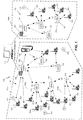
- FIG. 1 depicts a simplified block diagram of an irrigation system 100 in accordance with some embodiments.
- the irrigation system 100 includes a central irrigation control system or controller 110, a communication network 115 (which can include wired and/or wireless communication), one or more satellite irrigation controllers 120, a field transmitter 125, one or more wireless network interfaces or Master Radio Modules (MRM) 130 (each of which may generally be referred to as a wireless module or radio module), one or more wireless sub-network interfaces or Radio Relays (RR) 135 (each of which may be referred to as Slave Radio Relays or more generally, as wireless modules or radio modules), and one or more control modules 160 (also referred to as command modules), where each of the control modules may be cooperated with a radio adapter 165.
- MRM Master Radio Modules
- RR Radio Relays
- the irrigation system 100 can include one or more sensors 170.
- the sensors 170 in some instances, can cooperate with and/or communicate directly to a control module 160, an MRM 130, an RR 135, a satellite irrigation controller 120 and/or the central irrigation controller 110. Utilizing these components, the irrigation system 100 is configured to allow for the remote management of one or more, and typically many control modules 160 using the central irrigation controller 110.
- the control modules 160 are in-ground or positioned below a ground level. The control modules 160, however, can be positioned on ground or above ground.
- the irrigation system 100 combines and cooperates irrigation system devices that were not intended to be cooperated within an irrigation system.
- the present embodiments can combine the use of AC powered irrigation control systems with DC battery powered controllers.
- the irrigation system 100 combines satellite irrigation controllers 120 that implement irrigation schedules over a relatively wide geographic area with control modules 160 that are local to valves, run valve specific schedules and typically do not include a user interface.
- the irrigation system 100 can incorporate local control modules that are typically independently controlled and intended to operate independently into a system that provides coordinate irrigation control.
- the present embodiments can provide enhanced irrigation control over areas that are typically hard or expensive to incorporate programmed irrigation control (e.g., landscaping on roadways, historic areas, and the like) while coordinating the controlled irrigation over a wide geographic area and/or in cooperation with a wide variety of irrigation control devices and/or irrigation systems.
- a central irrigation controller 110 can distribute irrigation schedules and/or irrigation commands to a plurality of irrigation devices, including the independently controlled control modules 160, to implement coordinated irrigation over the irrigation system 100.
- the MRM 130 in some embodiments, is cooperated with one of the satellite irrigation controllers 120. Further, the MRM 130 may, in some implementations, be mounted within the satellite irrigation controller 120.
- Each of the various control modules 160 that are cooperated with a radio adapter can interface with an RR 135 or an MRM 130.
- the RRs 135 interface wirelessly with an MRM 130.
- the MRMs communicate wired or wirelessly with a central control software application executed by the central irrigation controller 110.
- the central irrigation controller 110 can coordinate irrigation by generating irrigation schedules or be programmed by a user with irrigation schedules for the respective satellite irrigation controllers 120 and control modules 160.
- the irrigation schedules in some instances, define run times and/or desired amounts of water to be supplied through a station and/or water delivery devices (e.g., sprinklers, drip lines, etc.). Further, the irrigation schedules often define start times or times when the irrigation scheduling can be implemented. Accordingly, this allows the central irrigation controller 110, satellite irrigation controllers 120 and/or control modules 160 to manage start times and durations. Additionally, in some implementations, one or more flow thresholds can be defined and used by the central irrigation controller 110, satellite irrigation controllers 120 and/or control modules 160 in controlling irrigation.
- the central irrigation controller 110 can be located at the property being irrigated or be located remote from the property.
- the central irrigation controller 110 is located within wireless transmission range of the satellite irrigation controllers 120 (e.g., radio frequency, cellular or the like, and in some instances may have a wireless range of about 1000-3000 feet, while in other instances may have a range of greater than a mile).
- the central irrigation controller can be implemented on one or more computer devices implementing central irrigation control software provided by Rain Bird Corporation of Azusa, California, such as IQTM Central Control, Maxicom 2 ® Multi-Site Irrigation Central Control System, SiteControlTM Single Site Central Control System; or other relevant central control systems by Rain Bird Corporation or other companies.
- the central irrigation controller 110 and/or software implemented by the central irrigation controller manages communications with at least the satellite irrigation controllers 120 and MRMs 130.
- the communication with the satellite irrigation controllers 120, field transmitter 125, MRMs 130 and RRs 135 may be through a communication interface or Network Communication Cartridge (NCC) cooperated with the satellite irrigation controller 120.
- NCC Network Communication Cartridge
- Communications may be sent with error correction, may be sent multiple times and/or may be sent as separate actions, such as communicating two times in case of radio network action (e.g., a first communication for sending a command, and a second later communication to query for a command answer).
- the MRM 130 is configured to, in part, receive relevant irrigation schedules and/or irrigation commands for one or more control modules 160 and wirelessly distribute the relevant irrigation schedules and/or commands to the one or more control modules 160 that are cooperated with a radio adapter providing wireless communication with the MRM 130 or an RR 135.
- the control modules 160 are microprocessor-based irrigation control devices that each stores and executes at least one irrigation schedule.
- the control modules 160 are battery operated and do not have power lines. Accordingly, a control module battery (not shown) typically provides the only power to a control module 160 and allows the control module to implement valve or station specific irrigation schedules in the absence of AC power and in areas where AC power cannot be provided or it is impractical or too costly to provide AC power.
- an MRM 130 may communicate, via wired or wireless communication, with a field transmitter 125 to supply irrigation schedules to the field transmitter.
- the field transmitter 125 can then be communicationally coupled with one or more control modules 160 to communicate irrigation scheduling to those control modules.
- FIG. 2A depicts a simplified view of a control module 160 positioned within a valve box 212 (or other enclosure) and coupled with an irrigation valve 214, master valve or other valve, which in this example is also within the valve box 212, according to some embodiments.
- the valve can be substantially any type of valve or other controlled device.
- the control module 160 is positioned below ground level 224 within a valve box 212 or other enclosure.
- the valve 214 is cooperated with a water line 216 such that the opening and closing of the valve 214 controls the flow of water through the water line.
- a valve box lid or cover 218 is cooperated with the valve box 212 to provide some additional protection for the components within the valve box.
- FIG. 2B shows a simplified view of the valve box 212 of FIG. 2A with the lid removed and a field transmitter 125 communicationally coupled with the control module 160, according to some embodiments.
- a control module 160 may control one or more different valves (e.g., 1, 2, 4, 6 or more different valves or stations) depending on the number of outputs included during manufacturing (only one valve is shown for simplicity in FIGS. 2A-2B ).
- the control module 160 does not have a user interface.
- the field transmitter 125 can be used to directly supply and program irrigation scheduling into the control module 160.
- the field transmitter 125 is a portable, handheld user interface device.
- control module 160 It is coupled to the control module either through a directed wire or optical link connection cable attached to the field transmitter, or via a wireless communication link (e.g., radio frequency link) when the control module 160 is cooperated with a wireless radio adapter 165.
- a wireless communication link e.g., radio frequency link
- FIG. 2C depicts a simplified view of a control module 160 positioned within a valve box 212 (or other enclosure) and coupled with a valve 214, which in this example is also within the valve box 212, according to some embodiments.
- the control module 160 is cooperated with or includes a radio adapter 165 that allows wireless communication between the control module 160 and the field transmitter 125, an RR 135 and/or MRM 130.
- the field transmitter 125 can be used to directly provide irrigation scheduling to the control module 160 and/or radio adapter 165 without the valve box lid 218 having to be opened, and in some instances, can be performed at a distance from the control module (e.g., 30 feet or more).
- a RR 135 and/or MRM 130 can alternatively or additionally wirelessly communicate with the radio adapter 165 and control module 160 to, in part, provide irrigation scheduling, provide command and/or obtain information from the control module and/or radio adapter.
- FIG. 3A depicts an illustration of a field transmitter 125 in wireless communication with a radio adapter 165 that is cooperated with the control module 160, in accordance with some embodiments.
- the radio adapter 165 in some embodiments, can be used to retro-fit with some existing control modules allowing these existing control modules to be utilized within the irrigation system 100.
- the radio adapter 165 in at least some implementations, can be configured to allow wireless communication between the control module 160 and an MRM 130 or an RR 135, which can improve the distribution of irrigation scheduling and/or avoid having a user go out to the control modules and utilize the field transmitter 125 to manually distributed the irrigation schedules.
- the field transmitter 125 can continue to be used to directly communicate with and supply irrigation programming and/or other information to a control module 160 and/or radio adapter 165.
- the communication with the radio adapter can be wireless directly from the field transmitter 125.
- the field transmitter 125 can utilize the MRM 130 and/or one or more RRs 135 in relaying information to a radio adapter 165.
- the handheld field transmitter 125 can wirelessly transmits irrigation programming or other information to the MRM 130.
- the MRM can wirelessly relaying the irrigation programming or other information from the MRM to the radio adapter that is directly cooperated with and communicationally coupled with the control module.
- the communication to the radio adapter may further include one or more relays through one or more RRs 135.
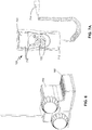
- FIG. 3B shows a perspective view of a control module 160 directly, communicationally coupled with the field transmitter 125.
- the field transmitter can direct communicate with the control module 160. This communication, however, is typically through direct connection via a wire, direct connection interface or cord, or other such connection.
- the direct connection provides optical communication between the field transmitter 125 and the control module 160.
- the control module includes one or move valve drivers (internal to the control module and not shown in FIG. 3B ) that couple with one or more valves 312.
- FIG. 4 shows a perspective view of a control module 160 in accordance with some embodiments.
- the control module 160 includes a housing 412, a communication interface or port 414, one or more valve wires or lines 416 and a battery compartment 418 (which may be a separate compartment that may be watertight) into which a control module battery can be inserted.
- the control module 160 typically includes (although not depicted in FIG. 4 ) one or more processors, controllers, memory, signal receivers, transmitters and/or transceivers, detectors, decoders, encoders and valve drivers positioned within the housing 412.
- the control module 160 can include a master valve output 420.
- the one or more valve drivers couple with the valve lines 416 and/or master valve output 420.
- the control module 160 can be configured to be battery-operated so that power lines do not need to be laid, which can simplify the installation and/or allow the control module to control irrigation in places where it would be difficult and/or costly to lay power lines.
- the control module 160 is a microprocessor-based irrigation control device that stores and executes one or more irrigation schedules. As described above, the control module can be located below ground level, typically within a valve box 212, and directly coupled to one or more irrigation valves 214. Again, the control module 160 may be configured without a user interface. Accordingly, a field transmitter 125, an MRM 130 and/or an RR 135 can be used to program the irrigation scheduling into the control module 160.
- the communication interface 414 is an optical communication interface with one or more lenses positioned to direct optical signals from the field transmitter 125 to one or more optical sensors and/or detectors within the control module 160.
- the radio adapter 165 can be cooperated with the control module 160.
- the radio adapter 165 has a corresponding communication interface, port, cable, cord or the like that can cooperate with the control module 160 and/or the communication interface 414 of the control module.
- the optical communication to or from the control module 160 can employ substantially any optical communication, such as infrared communication.
- the control module 160 includes one or more processors, controllers, memory, signal receivers, detectors, decoders and valve drivers, and the control module 160 is configured to receive (e.g., optically receive) programming, irrigation scheduling and/or irrigation commands, and implement at least the relevant portions of the programming, irrigation scheduling and/or commands.
- the housing 412 is sealed to inhibit or prevent water from entering the housing.
- the control module 160 is configured to meet and/or exceed an Ingress Protection Rating of IP68 (in accordance with the international standard of the International Electrotechnical Commission (IEC) 60529), potted and can be fully submersible.
- the control module 160 can be implemented through a TBOSTM control module available from Rain Bird Corporation of Azusa, California.
- control module 160 can further couple with one or more sensor devices 170 (e.g., rain, soil moisture, rain/freeze, wind, flow, water meter, and/or other such sensors).
- the sensors 170 are cut off type sensors providing a cut off signal at a predefined threshold.
- the control module 160 utilizes the sensor information in controlling irrigation, such as preventing activation of scheduled irrigation in response to a rain sensor signal indicating detected rain fall and/or a detected predefined threshold amount of rain fall.
- the one or more valve drivers of the control module 160 activate the one or more valves 214 coupled with the control module.
- the valve drivers are configured to send activation and deactivation signals to latching solenoid control valves.
- the control module 160 is configured, in at least some implementations, with current limiting protection that prevents the solenoid driver circuit from destruction under station output short-circuit conditions.
- the irrigation programming and/or irrigation schedule that can be incorporated into the control module 160 can include substantially any relevant irrigation scheduling.
- the control module 160 provides: multiple independent programs (e.g., three), which each having one or more start times (e.g., eight start times each); multiple potential cycles (e.g., custom, odd, odd31, even, 1 to 31 Day Cyclical day cycles, and the like); adjustable station run times (e.g., adjustable from 1 minute to 12 hours); water budget per program and/or per month (e.g., 0% to 300%); calendar day off; rain delay (e.g., from 1 to 14 days); manual station, program, and test program start, advance, cancel; master valve and sensor programmable by station; and/or other such programming and/or scheduling.
- multiple independent programs e.g., three
- start times e.g., eight start times each
- multiple potential cycles e.g., custom, odd, odd31, even, 1 to 31 Day Cyclical day cycles, and the like
- adjustable station run times
- battery can typically be replaced without losing the programming and/or irrigation scheduling.
- battery levels of the control module 160 and/or radio adapter 165 can be communicated to the MRM 130 and/or central irrigation controller 110 (e.g., in response to a request).
- the control module 160 can be accessed and/or programmed through various methods.
- a user can access the control module 160 using substantially any remote computer or other device configured to communicate over a distributed network (e.g., the Internet) through the MRM 130.
- the field transmitter 125 can communicate with the control module 160 through the radio link and/or the Infra-red link.
- FIG. 5 depicts a simplified perspective view of a radio adapter 165 in accordance with some embodiments.
- the radio adapter 165 includes a housing 512, battery compartment 514 (which may be a separate compartment and/or separate watertight compartment), and an antenna 516 that cooperates with a wireless receiver, transmitter and/or transceiver (not shown) within the housing 512.
- the radio adapter includes one or more communication interfaces, ports, cords, cables or the like (not depicted in FIG. 5 ). At least one of these communication interfaces is configured to cooperate with the communication interface 414 of the control module.
- the communication interface of the radio adapter is an optical communication interface that can cooperate with and/or otherwise mate with the communication interface 414 of the control module 160.
- the cooperation between communication interfaces can be substantially any cooperation, such as but not limited to threaded, male-female compression fit, snap-fit, or other relevant coupling.
- the radio adapter 165 typically includes (although not depicted in FIG. 5 ) one or more processors, controllers, memory, wireless signal receivers, transmitters and/or transceivers, detectors, decoders and encoders positioned within the housing 512.
- the radio adapter can also be configured to be battery-operated. As such, the radio adapter battery, in at least some embodiments, is configured to provide the only power to the radio adapter.
- the housing 512 is sealed to inhibit or prevent water from entering the housing.
- the radio adapter 165 is configured to meet and/or exceed an Ingress Protection Rating of IP68, potted and can be fully submersible.
- the housing 512 of the radio adapter 165 in at least some implementations, can be constructed of plastic, Acrylonitrile butadiene styrene (ABS), Polyvinyl chloride (PVC), wood, metal or other relevant materials or combinations thereof that are compatible with and/or do not interfere with the wireless communication.
- the housing is formed through an injection molding or process (e.g., ABS injection), with ultraviolet (UV) stabilized plastic material.
- the housing and/or seams of the housing can be sealed, and in some embodiments is potted to obtain IP68 conformity (e.g., 100% watertight and entirely submergible).
- the embodiment of the radio adapter 165 shown in FIG. 5 is separate from the control module 160 and is in communication with and/or cooperated with the control module 160 through one or more communication interfaces. In other embodiments, however, the radio adapter 165 can be implemented as part of the control module 160, e.g., integrated with or within the housing of the control module 160.
- the radio adapter 165 is a microprocessor-based wireless receiver (and in some instances wireless transmitter) device that receives programming and/or irrigation scheduling and communicates the programming and/or commands to the control module 160.
- the wireless communication can be substantially any radio or other wireless communication, such as but not limited to wireless communications in the industrial, scientific and medical (ISM) radio bands (as defined by the ITU-R (International Telecommunication Union, radio communication sector) in 5.138, 5.150, and 5.280 of the Radio Regulations), for example 868 and 915 MHz, for the single cooperated control module 160, or other relevant wireless communication and/or communication bands.
- Some embodiments may additionally implement frequency hopping (e.g., frequency hopping spread spectrum) or direct sequence spread spectrum.
- the use of the direct sequence spread spectrum can be implemented using one frequency with a relatively large bandwidth (e.g., +/-100 KHz, +/-250 KHz, or the like).
- the transmitted signal may take up more bandwidth than the information signal that is being modulated, but typically cause limited or no interference for other systems and/or system components.
- the receiving device demodulates the signal to recover the initial information.
- the direct sequence spread spectrum may provide some advantages over the frequency hopping spread spectrum method, such as but not limited to, increased battery life duration (e.g., synchronization may not be needed), increased radio rate (e.g., a slack period may be avoided that might otherwise be included due to synchronization phase), simplified installation of the wireless and/or radio communication network 115 or the addition of a new device on an existing wireless communication network 115 (e.g., no synchronization needed), may not have to operate with a precise frequency (e.g., drift due to temperature or other such factors), and can provide good interference immunity (e.g., by choosing a productive spreading code).
- increased battery life duration e.g., synchronization may not be needed
- increased radio rate e.g., a slack period may be avoided that might otherwise be included due to synchronization phase
- simplified installation of the wireless and/or radio communication network 115 or the addition of a new device on an existing wireless communication network 115 e.g., no synchronization needed
- the wireless communication range between the field transmitter 125 (e.g., transmitting at 25 mW) and the radio adapter 165 incorporated below ground level in a plastic valve box is configured to be at least five feet, but in some instances can be as much as 200 feet or more, and is typically limited by the transmission power of the field transmitter 125.
- the wireless communication between the radio adapter and an MRM 130, RR 135 or other relevant repeater can be greater, such as in the range of as much as about 1000-1500 feet or more (with a 25 mW transmission power), depending on the relative positioning (e.g., height of the antenna), obstacles and the like.
- the communication between the radio adapter 165 and the control module 160 is also wireless, such as optical (e.g., infrared communication).
- the antenna 516 of the radio adapter 165 couples with the receiver, transmitter and/or transceiver within the housing 512 and extends from the housing 512.
- the radio adapter 165 is configured to communicate information (e.g., parameters, irrigation programs and/or schedules, operating conditions, battery levels, sensor information, and the like) to and/or receive information (e.g., schedules, sensor information, etc.) from the MRM 130, satellite irrigation controller 120 and/or central irrigation controller 110.
- the radio adapter 165 is configured to communicate and/or act as a radio relay that communicates or relays information (e.g., parameters, irrigation programs and/or schedules, operating conditions, battery levels, sensor information, and the like) between the control module 160 and the MRM 130, satellite irrigation controller 120 and/or central irrigation controller 110.
- control modules 160 with which a radio adapter 165 may cooperate may vary, having different functionalities and/or capabilities.
- some control modules 160 may have limited memory, have older processors and/or irrigation control software, and/or have other limited capabilities.
- the control module may be a legacy control module and/or earlier version of a control module with a first function set, while other control modules may be later versions, newer or upgraded control modules with a second function set, where the first function set is a reduced function set or has limited functions relative to the second function set that provides enhanced, greater or different functionalities.
- the radio adapter 165 is further configured to detect a type of control module 160 with which the radio adapter is communicationally coupled.
- the radio adapter 165 may perform different functions. For example, when the radio adapter 165 detects that the control module 160 is a legacy control module and/or has a certain first level of functionality that is less than a second level of functionality for another type of control module, the radio adapter 165 may serve as an irrigation program controller as well as operate as a radio relay.
- the radio adapter may copy the one or more irrigation commands and/or irrigation programs to be implemented by the control module 160.
- the radio adapter can implement the irrigation commands and/or irrigation schedules using the functionality of the legacy control module to open or close valves.
- the radio adapter 165 can provide functionality to the combination of the radio adapter and the legacy control module to provide functionality that is at least similar to or the same as newer control modules or control modules with enhanced or greater functionality than the legacy control module.
- the control module 160 can operates as a slave to the radio adapter implementing instructions from the radio adapter 165.
- the radio adapter 165 may simply serve as a radio relay.
- the radio adapter 165 may further be configured to detect when it has been moved from coupling to a first type of control module to a second different type of control module and notify the MRM 130, satellite irrigation controller 120 and/or central irrigation controller 110, and/or take appropriate action relative to its operation relative to the different functionalities available to the second control module.
- the radio adapter 165 can further provide control modules 160 with additional functionality.
- one or more irrigation programs and/or schedules on a control module 160 can be copied the radio adapter 165, which in part can add new irrigation functionalities without modification of the control module, software of the control module and/or firmware of the control module.
- the radio adapter 165 is operated from battery power, which can be substantially any battery having sufficient stored energy to power the reception and/or transmission of wireless communications and the forwarding and/or reception of information to the control module 160 (e.g., a single alkaline 9V battery 6AM6 type (international certifications) or 6LR61 type (European certifications)).
- the radio adapter 165 may obtain power from the control module 160 or other device with which the radio adapter connects.
- the cooperation between the radio adapter 165 and the control module 160 provides an optical communication path (e.g., infra-red communication). Further, a water tight seal may be established to prevent water from interfering with the optical communication.
- FIG. 6 depicts a perspective view of a control module 160 cooperated with and in communication with a radio adapter 165 in accordance with some embodiments.
- the radio adapter 165 is physically cooperated with and secured with the control module 160.
- the radio adaptor 165 can be secured with the control module 160 such that the optical communication interface 414 of the control module is aligned with a similar optical communication interface or port on the radio adapter 165.
- the optical interfaces seal together through a male-female cooperation.
- the control module 160 and the radio adapter 165 may, in some instances, include additional latching, tongue-and-groove, snap-fit, grooves, recesses, extensions, and/or other such mechanisms for maintaining the positioning between the control module 160 and the radio adapter 165.
- the radio adaptor 165 can be cooperated with the control module 160 through other communication mechanisms, such as through other wired communication, wireless communication or the like. Similarly, when the radio adapter 165 is physically cooperated with the control module, the physical cooperation can be through substantially any method, such as but not limited to sliding into a slot, snap fit, latching, adhesive, clamps, compression fit, and other such methods. In an example that is not part of the present invention, the radio adaptor 165 is incorporated with or into the control module 160 as a single device or unit.
- FIG. 7A depicts a simplified overhead view of a field transmitter 125 in accordance with some embodiments.
- the field transmitter 125 includes a housing 712, a physical direct connection interface or cord 714 (e.g., optical or fiber optic cable), and a user interface 716. Further, as described above, the field transmitter further comprises one or more processors, controllers, memory, wireless signal transmitters, receivers, and/or transceivers, detectors, decoders and encoders positioned within the housing 712. In some instances, one or more additional communication interfaces (e.g., USB or other such communication interface) can be included to allow the field transmitter 125 to communicate with the central irrigation controller 110, computer, MRM 130, RR 135 or other relevant device.
- additional communication interfaces e.g., USB or other such communication interface
- the field transmitter 125 is typically battery operated, often through a rechargeable battery. Accordingly, one or more of the communication interfaces can further provide power to charge the battery, or another port can be included to receive power. In some embodiments, the battery of the field transmitter can be rechargeable, such as through an AC external power plug.
- the field transmitter 125 is configured to communicate with and provide configuration and programming to the control modules 160 and radio adapters 165.
- the communication can be via wireless communication through the radio adapter 165 and/or through direct communication using the connection cord 714, which in some embodiments establishes Infrared communication.
- the cooperation of the direct connection cord 714 and the communication interface 414 of the control module 160 can be through substantially any cooperation, such as but not limited to threaded. press-fit, snap-fit, compression fit and other relevant methods.
- the field transmitter 125 in at least some embodiments, is further configured to provide wireless communication with one or more radio adapters 165 and control modules 160, MRMs 130, RRs 135 and/or other relevant devices.
- An irrigation network can be implemented without the central irrigation controller, MRM and RRs, and using the control modules, radio adapters 165 and field transmitters.
- the central irrigation controller 110, the MRMs 130 and/or RRs 135, however, provides additional functionality, control, cooperation, enhanced distribution, and other features to the irrigation system 100.
- the direct connection cord 714 is removable from the field transmitter 125 such that the field transmitter solely provides wireless communication when removed.
- the field transmitter 125 can include a removable panel that can allow the direct connection cord 714 to be disengaged from an optical transmitter and/or transceiver internal to the housing 712.
- the field transmitter 125 can wirelessly communicate with radio adapters 165, MRMs 130 and/or RRs 135 through radio or other wireless communication, such as but not limited to one or more of the ISM radio bands.
- the ranges of wireless communication can vary depending on many factors, such as transmission power, obstacles, interference and the like.
- the field transmitter has a range with the radio adapter positioned in a valve box and transmission at 25 mW to be at least 5 ft, and in some instances can be 350 ft. Communication ranges with the MRM 130 and/or RR 135 is typically greater.
- the field transmitter 125 can further communicate wirelessly with one or more control modules 160 through an MRM 130 and radio adapter equipped control module and/or through a RR 135 and radio adapter equipped control module. Some embodiments additionally provide secure or private communications.
- security software and/or a security chip can be included in a field transmitter 125, MRM 130, RR 135, control modules 160, and/or radio adapter 165 to provide a challenge and/or authenticate security protection to radio and/or optical communications between components of the irrigation system 100. These protections can, in some instances, prevent components of the irrigation system from intercommunicating unless they have succeeded in authenticating each other.
- the field transmitter 125 can be configured to measure radio ranges in the field between MRM and RRs, between RRs, and between MRM or RR and a radio adapter. This can aid a user, at least in part, in identifying placement of RRs, radio adapters and the like in configuring the irrigation system 100.
- the user interface 716 of the field transmitter can include one or more of a display 720, buttons 722, scroll wheel and/or other such mechanisms allowing the user to interact with the field transmitter 125.
- the display 720 can be a Liquid Crystal Display (LCD), LCD with backlighting, touch screen display, and/or other relevant display.
- the buttons 722 or other user interaction options which can be physical and/or displayed, can allow the user to access information displayed through the display and/or to activate the field transmitter 125 to take action, such as to communicate programming and/or scheduling to a control module 160.
- the display can display a large amount of information, for example, through the display of various menus (which may be displayed in accordance with a user selected language).
- the user interface 716 can allow a user to view operations of the field transmitter 125, receive information about the field transmitter, the irrigation system 100, a control module 160, sensors, or other device of the system, input information and/or irrigation schedules and take other actions.
- the field transmitter 125 can be powered by an AC power source and/or battery (e.g., one or more rechargeable batteries).
- the display 720 can show menus that can be used by the user. In some instances, the menus are displayed as scrolling menus.
- the field transmitter can allow a user to define a name for the field transmitter, a control module 160, radio adapter 165, irrigation valve, irrigation station and/or irrigation program.
- the field transmitter can be configured to allow a user to select one of a plurality of desired languages.
- One or more irrigation programs can be locally saved within the field transmitters. These saved irrigation programs can be communicated to control modules and/or used to restore a control module.
- the field transmitter may provide a rain delay function or instruction (e.g., 1 to 14 days) that can be communicated to one or more control modules 160 and/or radio adapters 165.
- the field transmitter 125 and/or the central irrigation controller 110) can check irrigation programs of control modules 160 and/or check the implementation or history of these programs.
- the field transmitter in some implementations can be configured to allow a user to select one or more irrigation cycles per irrigation program (e.g., one or more of cycles A, B or C). Further, in some embodiments, the field transmitter may define a water budget per program (e.g., A/B/C) and/or per month (which may be defined by the central irrigation controller 110, a user or obtained from another source, such as third party source). In some embodiments, the field transmitter 125 is further configured to allow a user to initiate manual actions (e.g., activate an irrigation program, station or valve, interrupt irrigation, cancel irrigation (total or partial), delay irrigation, or other such actions). Additionally, the field transmitter 125 may display information to the user, such as irrigation station status information, sensor information, scheduling, and other relevant information.
- a water budget per program e.g., A/B/C
- per month which may be defined by the central irrigation controller 110, a user or obtained from another source, such as third party source.
- the field transmitter 125 is further configured to allow a
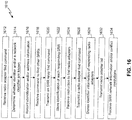
- FIG. 7B shows a block diagram representation of menu access and/or user interface menus accessible through the field transmitter 125 in accordance with some embodiments.
- the same or similar menu access and/or user interface menus may be available through the central irrigation controller 110 and/or an MRM 130 through a user interface of a satellite irrigation controller 120.
- the field transmitter 125 is configured to display relevant menus depending on the type of connection, the device the field transmitter is communicating with, the functionalities and/or programming of the device being communicated with, and other factors and/or combinations thereof.
- the field transmitter 125 may display menus and/or functions according to different menu sets.
- a first menu set may be implemented by the field transmitter, for example, when the field transmitter is directly coupled (e.g., Infrared link) with a limited capability control module 160 and/or legacy control module.
- a second menu set may be implemented by the field transmitter when directly connected (e.g., Infrared link) with a control module having greater capabilities than the limited or legacy control modules; or when connected through a radio adapter 165 with a limited capability, legacy or advanced capability control module 160.
- a third menu set may be implemented by the field transmitter when connected through a radio adapter with a control module 160 configured to cooperate with the central irrigation control software.
- a fourth menu set may be implemented when the field transmitter 125 is connected through a radio adapter 165 with a limited capability or legacy control module 160 when the control module is configured to cooperate with the central irrigation control software.
- Other menu sets can also be provided.
- still other menus and/or menu sets may be provided when the field module is in communication with an MRM 130 or RR 135. The variations in capabilities, functions and the like provided through the different menu sets can depend on the control modules and/or radio adapters.
- menus, controls and features can be accessed through the field transmitter 125, used to implement communication and/or to program the control modules 160 and/or radio adapters 165.
- Some of the menus and/or menu features can include: initial configuration of the field transmitter 125, setting time/date, adjusting the contrast, customize the field transmitter name, field transmitter language selection, setting the screen lighting time, restore initial settings, displaying field transmitter data, programming the field transmitter, creating irrigation schedules, defining watering days, setting start times, setting watering run times, transmitting irrigation time, date and program, defining water budget programming, setting seasonal adjustment (e.g., per program, per month, etc.), reading irrigation programs, transmitting an irrigation programs, canceling irrigation (in total, partial), manual station launch, manual program launch, irrigation test on one or more or all stations, rain ON/OFF and/or rain delay, saving irrigation programs, saving irrigation programs into a control module 160 and/or radio adapter 165, customization of control modules and stations names, radio marking, defining or changing a network number of radio devices, radio finding of
- FIG. 8 depicts a simplified example of buttons 812-818 of a user interface 716 of a field transmitter 125 in accordance with some embodiments.
- the buttons can provide one or more functions, which may depend on a state of operation and/or the information or options presented on the display 720.
- the buttons can include a main menu or home button 812, a irrigation program navigation button 813, up, down, left and right buttons 814-817, respectively, and an enter, select and/or "OK" button 818.
- the main menu button 812 can, when selected, cause the field transmitter 125 to return to and display a main menu that allows the user to interact with the field transmitter.
- the main menu button 812 can further act as a power button by, for example, pressing and holding the main menu button for a predefined period of time (e.g. 2-3 seconds).
- the up button 814 may provide multiple different functions depending on a state of operation.
- the up button 814 may cause a scrolling upwards through a menu; may cause an increase in a numerical value (or higher value) when a data input mode is displayed; may cause an confirmation of watering day "ON" or station “ON” mode of operation when defining an irrigation schedule or an manual override; and/or other such functions.
- the down button 815 can provide multiple functions depending on a state of operation, such as but not limited to, a scrolling down through menus; a decrease in a numerical value; a confirmation of an "OFF" watering day or station “OFF” mode of operation; and/or other such functions.
- the left button 816 can provide functions such as, but not limited to, causing a scrolling left through different menus; transitioning through a menu to an option to the left; causing a transition to a previous menu (e.g., a "back" command); resetting a numerical value; validating an entry; and/or other such functions.
- the right button 817 similar to the left button, provides functions such as, but not limited to, causing a scrolling right through different menus; transitioning through a menu to an option to the right; causing a transition to a subsequent menu (e.g., a "forward" command); confirming an input; and/or other such functions.
- the central irrigation controller 110 can be a dedicated central irrigation control device or can be implemented through a computer, such as a desk top computer or laptop, multiple computing devices, computers, servers and/or such devices distributed over one or more networks (e.g., local area network, home area network, a wide area network and/or the Internet), or other relevant devices or combinations of devices. Further, the central irrigation controller 110 can receive modifications to irrigation scheduling and/or can determine adjustments to irrigation scheduling, such as adjustments with regards to environmental conditions, pump loads, volumetric water budgets, scheduling changes at one or more satellite irrigation controllers 120 or control modules 160, power issues, other problems or the like. The central irrigation controller 110 can communicate with the satellite irrigation controllers 120 through wired or wireless communication methods.
- the central irrigation controller 110 can further communicate over a distributed network with one or more other remote devices and/or services, such as a weather data service, an evapotranspiration (ET) data service, a water authority, historic information service or storage device (e.g., historic weather data, historic ET data, and other such historic data), and other relevant devices and/or services.
- a weather data service e.g., an evapotranspiration (ET) data service
- a water authority e.g., evapotranspiration (ET) data service
- historic information service or storage device e.g., historic weather data, historic ET data, and other such historic data
- the central irrigation controller 110 can be remotely accessed by one or more users from over a network via a computer, wireless device (e.g., personal digital assistant, cellular phone, laptop, or other such wireless device), or other such devices.
- wireless device e.g., personal digital assistant, cellular phone, laptop, or other such wireless device
- the one or more satellite irrigation controllers 120 can further couple with one or more irrigation valves to control the water flow to one or more water distribution devices and/or systems (e.g., sprinklers, drip lines, etc.) in implementing one or more irrigation schedules.
- the satellite irrigation controllers 120 can be implemented through one or more of the satellite irrigation controller embodiments described in U.S. Patent Nos. 7,640,079 , 7,844,367 , U.S. Patent Application Serial No. 12/837,381, filed 07-15-2010, for Marsters et al. , entitled METHOD AND APPARATUS FOR PROGRAMMING A DECODER-BASED IRRIGATION, and/or U.S. Patent Application Serial No.
- the MRM 130 is cooperated with a satellite irrigation controller 120.
- the MRM 130 may be positioned exterior to the satellite irrigation controller 120 and communicationally coupled with the satellite irrigation controller.
- the MRM 130 may be positioned within the satellite irrigation controller and receive power from the satellite irrigation controller.
- the MRM 130 can be positioned within a module slot of a modular satellite irrigation controller configured to receive one or more modules that provide various functionalities to the satellite irrigation controller.
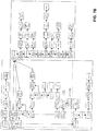
- FIG. 9 depicts a simplified diagram of a satellite irrigation controller 120 cooperated with an MRM 130, according to some embodiments.
- the satellite irrigation controller 120 can communicationally couple with the central irrigation controller 110 through wired or wireless communication at least in part to receive irrigation scheduling. Further, the satellite irrigation controller 120 can receive or communicate new irrigation scheduling, modifications or overrides to irrigation scheduling, and/or can determine adjustments to irrigation scheduling.
- the satellite irrigation controller 120 may be a decoder-based satellite irrigation control system.
- the satellite irrigation controller 120 can send operational power and data over a multi-wire (e.g., 2 or 3 wire) transmission line to one or more decoder units (e.g., decoder units) each coupled at various locations to the multi-wire line (not shown).
- Each decoder unit derives operational power from the multi-wire line and controls the operation of one or more irrigation valves or other sprinkler devices.
- the satellite irrigation controller 120 can functionally include or be coupled to a field interface device that modulates or encodes data, typically on a power waveform, to power and address and communicate with the decoder units.
- the satellite irrigation controller 120 may include an encoder module that can encode signals onto the multi-wire transmission line.
- Decoder-based systems are generally well-known in structure and operation by those of ordinary skill in the art.
- An example of a known decoder system includes the PAR+ES Decoder controller system and FD-101, FD-102, FD-202, FD-401 and FD-601 decoders commercially available from the Rain Bird Corporation.
- the satellite irrigation controller 120 includes a control panel 912 cooperated with a housing 914.
- the control panel 912 can include a user interface (not shown) that can comprise, for example, one or more displays, buttons, rotary dial, switches, indicators, light emitting diodes (LEDs), and/or other features and/or elements.
- the control panel 912 can be removably secured within the housing 914. In FIG. 9 the control panel 912 is rotationally secured with the housing allowing the control panel 912 to swing out exposing a backside of the control panel and to expose a back plane 916 positioned within the satellite irrigation controller housing 914.
- control panel 912 can further cooperate and/or receive a communication interface or Network Communication Cartridge (NCC) 930.
- NCC Network Communication Cartridge
- the NCC 930 couples with the control panel 912 and, in some instances, mounts to and/or within the backside of the control panel (e.g., within a receiving port or interface of the control panel).
- the communication between the NCC 930 and the MRM 130 is over a separate wired communication link (e.g., RS-485 bus, ribbon cable, coaxial cable, etc.), the back plane 916 or other communication path.
- memory of the NCC 930 stores executable program code or instructions that when executed by a processor of the NCC causes the NCC to perform one or more functions, such as but not limited to communicating with other devices, communicating with the control panel 912, communicating with an MRM 130, communicating with another NCC of another satellite irrigation controller, reflashing the control panel 912, and/or other such functions.
- the NCC 930 can be implemented from an NCC provided by Rain Bird Corporation.
- the MRM 130 can appear to the satellite irrigation controller 120, in at least some embodiments, as a client satellite to the control panel 912.
- the satellite irrigation controller 120 can communicate with the MRM 130 and/or implement some control relative to the MRM, one or more RRs, or one or more control modules 160 within an MRM network 140 associated with the MRM associated with the satellite irrigation controller 120.
- the satellite irrigation controller can cause the MRM 130 to initiate one or more manual commands and/or the control panel 912 of the satellite irrigation controller 120 can include a display (not shown in FIG. 9 ) that can be used to display information about one or more control modules 160, radio adapters 165, the MRM 130 and/or RR within an MRM network 140, which may have been obtained in some instances through the manual commands.
- commands and/or information can include substantially any relevant commands and/or information such as, but not limited to, display battery level, test battery level, time stamp of last battery level check, start valve or station, start irrigation program, cancel all, test all valves or stations, rain delay, auto/off, synchronize, reverse synchronize, retrieve logs, MRM/RR firmware or other programming version, update MRM/RR firmware or programming, and/or other such information or commands.
- one or more MRMs 130 can be coupled with or installed in the satellite irrigation controller 120.
- the MRM 130 may be positioned in one or more module mounting slots of the back plane 916.
- the MRM 130 can, in some implementations, receive power through the satellite irrigation controller 120, for example, from a transformer 934 cooperated with the back plane 916.
- the MRM 130 couples with an antenna 936 to provide the wireless communication.
- the NCC 930 can support telemetry from the satellite irrigation controller 120 and the MRM 130 to the central irrigation controller 110 or another satellite irrigation controller.
- the MRM 130 provides wireless communication with the one or more control modules 160 through coupled radio adapters 165, one or more RRs 135 and/or the field transmitter 125.
- the communication between the MRM 130 and the one or more RRs 135 can further relay information between the MRM 130 and the control modules 160.
- the wireless range of the MRM can depend on the device receiving the communication, the obstacles or barriers between the MRM and the receiving device, absorption, reflection, antenna position, the transmission power and/or other relevant factors, and typically a combination of multiple factors.
- the MRM 130 wirelessly transmits using 25 mW power in one or more of the ISM bands or other wireless communication bands.
- the range between the MRM and an RR can be about 4000 feet in an open environment. This range may be greater in some instances, such as with an RR being positioned above ground level (e.g., 6-50 ft or more above ground level). Again, the range can vary depending on implementation, power, etc.
- the MRM 130, RR 135 and/or other devices of the irrigation system 100 may additionally implement frequency hopping (e.g., frequency hopping spread spectrum) or direct sequence spread spectrum, as described above.
- the MRM 130 can be configured to communicate with substantially any number of control modules 160, RRs 135 and/or field transmitters 125. In some configurations, however, the number of control modules 160 that can be directly supported by an MRM 130, and/or the number of RRs 135 that can be supported may similarly be limited.
- an MRM 130 may in some instances be configured to directly support up to 32 control modules 160, and to further support wireless communication with up to 15 RRs 135, which allows the MRM 130 to support communication with a total of up to 512 control modules 160 from RRs 135 interfaced to the MRM 130 (e.g., 32 control modules supported directly from the MRM and an additional 480 control modules (i.e., 32 control modules x 15 RRs)).
- Other implementations can be configured to support larger or smaller numbers of modules, RRs, MRMs, and/or other devices (e.g., depending on memory, processing capabilities, communication protocol utilized, etc.).
- the central irrigation controller 110 can support substantially any number of MRMs 130, RRs 135 and/or control modules 160. Again, however, some embodiments may apply limits due, for example, to memory capacity, bandwidth, delays and other relevant factors.
- the central irrigation controller 110 and/or central irrigation control software implemented by the central irrigation controller may be configured to manage up to about 250 MRMs by different communication modes. This configuration, however, could enable potentially up to 128,000 control modules 160 (i.e., if each of the 250 MRMs were loaded to a 512 control modules per corresponding MRM network).
- each MRM may be limited to manage up to 512 control modules 160 (e.g., directly controlling up to 32 control modules, and up to an additional 480 control modules through up to 15 RRs 135, where the RRs are limited to manage up to 32 control modules). Accordingly, limits to the number of MRMs 130, RRs 135 and/or control modules 160 may apply for a given irrigation system 100.
- FIG. 10 depicts a simplified overhead view of an MRM 130 according to some embodiments.
- the MRM 130 includes a housing 1012, an antenna connector 1014 and one or more communication interfaces or ports 1016-1017.
- one or more indicators 1020-1021 can be included (e.g., LEDs) that indicate operations and/or states.
- the MRM 130 can further include mountings or other structure (not shown) to allow the MRM to cooperate with the back plane 916 of the satellite irrigation controller 120.
- One or more of the communication interfaces 1016 can be configured to allow the MRM 130 to connect with the NCC 930. Further, in some embodiments, a second communication interface 1017 can connect with another MRM 130 to allow daisy chaining of MRMs and increase the number of control modules that can be controlled without having to employ a second satellite irrigation controller 120. In some instances, an MRM may have a fixed address on a communication bus, and accordingly, a single MRM may be addressed over the bus.
- the antenna connector 1014 is configured to connect the MRM 130 with the antenna 936. In some embodiments the antenna 936 extends exterior to the satellite irrigation controller housing 914 (e.g., through a punch-out in the housing).
- FIG. 11 depicts a perspective view of an RR 135 according to some embodiments.
- the RR 135 of FIG. 11 includes a housing 1112 with a lid 1114.
- the housing contains one or more processors, controllers, memory, wireless signal receivers, transmitters and/or transceivers, detectors, decoders, encoders, antenna, and/or other relevant parts.
- the housing 1112 and/or lid 1114 can be constructed of plastic, PVC, metal, wood, fiber glass, or other relevant materials or combinations of such materials.
- the antenna is positioned vertically, and the lid 1114 can include an antenna protrusion 1116 that can protect the antenna while allowing wireless communication.
- the RR 135 can communicate with MRMs 130, other RRs 135, a field transmitter 125 and/or radio adapters 165.
- the RR 135 can include one or more exterior switches 1130 that can activate the RR 135, deactivate the RR, reset the RR, or cause the RR to perform other functions.
- one or more interior switches can additionally or alternatively be included.
- the exterior switch 1130 can be a magnetic switch that is exterior to and cooperated with the housing 1112 (e.g., on the lid 1114) that cooperates with an interior button, switch or the like. Accordingly, the exterior switch 1130 can cause the RR 135 to reset (or take other relevant action) without having to open the housing.
- the exterior switch 1130 can activate an internal switch or button that is detected by firmware of the RR that can in turn implement the reset or take other action.
- the same or a different exterior switch can additionally or alternatively cause the RR to broadcast its presence in attempts to communicationally couple with an MRM 130 and/or one or more radio adapters 165, initiate a radio marking of the RR 135 and/or cause other action.
- the exterior switch 1130 can, for example, be spring biased such that the switch returns to an initial state after being triggered by a user.
- the exterior switch 1130 can, in some embodiments, be associated with multiple different functions (e.g., by holding the switch for a first period of time can cause a first function, while holding the switch a second period of time can cause a second function; sequentially activating the switch a first predefined number of times causes an activation of a first function, while sequentially activating the switch a second predefined number of times causes an activation of a second function; or other such actions).
- multiple different functions e.g., by holding the switch for a first period of time can cause a first function, while holding the switch a second period of time can cause a second function; sequentially activating the switch a first predefined number of times causes an activation of a first function, while sequentially activating the switch a second predefined number of times causes an activation of a second function; or other such actions).
- the RR 135 can further directly communication with the field transmitter 125 such that no intermediary device is needed.
- the RR 135 can additionally operate as a relay or repeater for the field transmitter, repeating communications from the field transmitter to be delivered to a radio adapter 165 and control module 160, or from a radio adapter to the field transmitter.
- the RR 135 can operate as a relay or repeater for another RR 135, MRM 130, and/or a radio adapter 165.
- multiple RRs can be cooperated and/or daisy chained to repeat communications, for example, between an MRM 130 or field transmitter 125 and the radio adapters 165.
- the RR 135 can, in some implementations, be configured to be battery-operated so that power lines do not need to be laid, which can simplify the installation and/or allow the RR to operate in areas where it might be difficult and/or costly to lay power lines.
- power can be supplied to the RR (e.g., through power lines extending into the housing (not shown)).
- the RR can be mounted on a light pole and potentially receive power from the light pole.
- Some embodiments include a rechargeable battery, and/or can use battery power when a power source is non-continuous (e.g., when the RR is connected to a light pole and power from the light pole may only be available at night).
- the RR 135, in some implementations, can step down the power from the light pole to be used by the RR.
- a shelf or beams can be secured with a pole to allow the RR to be mounted on the pole.
- One or more straps, wraps, clamps, shelves, beams or the like can be used to position and/or secure the RR to a pole or other structure, or can be used to secure a shelf or beams to the pole or other structure.
- FIG. 12 depicts the RR 135 of FIG. 11 cooperated with a mounting kit 1210 to mount the RR on a pole 1212.
- the housing 1112 of the RR 135 can include mounting supports 1120 that cooperate with support beams or posts 1214 that extend from and/or are secured with a post mounting 1216.
- the mounting supports 1120 can be secured with the support beams 1214 through substantially any relevant method, such as but not limited to bolt and nut, rivet, welding, snap file, tongue and groove or other relevant mounting.
- the post mounting 1216 includes two opposing mounting brackets 1220-1221 that are positioned on opposite sides of the pole 1212 and can be secured together with bolts 1224 to establish a clamping force clamping the post mounting 1216 to the pole 1212.
- the pole 1212 can be substantially any diameter and/or shape, with the mounting brackets 1220-1221 having dimensions corresponding to or being larger than the diameter (or width) of the pole 1212.
- the mounting brackets 1220-1221 are configured as elongated, generally "U" shaped brackets with a series of holes drilled through a central portion allowing bolts to extend through to cooperate with the other mounting bracket and the support beams 1214.
- the lateral sides of the mounting brackets 1220-1221 may include a recess or inlet (e.g., semi-circular recess) that can cooperate with the pole 1212.
- the lateral sides may include or be cut to include ridges, teeth, or other structure that can help in gripping the pole 1212.
- the mounting brackets 1220-1221 can be implemented through other configurations, such as flat beams, a clamping structure depending on the shape of the pole 1212 (e.g., circular clamping structure), or other relevant configurations.
- the RR 135 in part increases the range between an MRM 130 (and/or field transmitter 125) and a radio adapter 165 and control module 160.
- the RR 135 can act as a relay between the MRM 130, another RR 135, a field transmitter 125 and/or a control module 160 and radio adapter 165.
- an RR 135 can further link to one or more RRs 135 and/or link multiple RRs in a chain further increasing the range and dispersion of the irrigation system 100.
- the number of RRs that a single RR can link to may be limited (e.g., up to 15 RRs), for example due to communication bandwidth, delays, memory, addressing, byte or bit space per communication, processing capabilities, and/or other such factors.
- An RR 135 can additionally or alternatively directly support and communicate with one or more control modules 160 and/or radio adapters 165. Again, the number of control modules 160 that can be supported by a single RR 135 may be limited based on the same or similar parameters, such as directly supporting up to 32 control modules 160.
- a first RR 135 (RR1) in a first MRM network 140a established a first RR network 150a that includes three control modules 160, with a sensor 170 cooperated with one of the control modules;
- a second RR 135 (RR3) in the first MRM network 140a establishes a second RR network 150b;
- a third RR 135 (RR8) in a second MRM network 140b establishes a third RR network 150c.
- the MRM 130 is configured to automatically identify and/or configure an MRM network 140.
- the MRMs 130 transmit or broadcast a network poll request, global message or request to find those control modules 160, radio adapters 165, RRs 135 and/or field transmitters 125 that are in wireless range of the MRM 130.
- Each control module 160, radio adapter 165, RR 135 and/or field transmitter 125 are similarly configured to wirelessly respond to the network poll request.
- the devices receiving the network poll request may repeat the replies (e.g., in random slots) and/or may employ a delay (e.g., a randomly generated delay, based on an ID, or other such factor) in transmitting a reply in attempts to limit or avoid collisions. Similarly, the devices may limit their respond to when the quality and/or signal strength of the network poll request signal exceeds a threshold.
- the MRM network polling can be prompted by the central irrigation controller 110.
- Each MRM 130 is further configured to build or identify its corresponding MRM network 140 based on radio signal strength indications (RSSI) and, in some instances, a network ID of received responses to the network poll request.
- a network ID can be a code (e.g., a string of alphanumeric characters, a four digit code, or other such code) programmed into control modules 160, radio adapter 165, RRs 135, field transmitters 125, MRMs 130 and other devices that may be configured in an MRM network 140 and/or that can communicate with an MRM 130.
- the IDs may be defined by a manufacturer.
- an ID e.g., a network ID code
- some devices may not have IDs or be configured to communicate an ID in response to a poll request. Accordingly, the MRM 130 may not require a device ID in order to include a device within an MRM network 140.
- the use of the ID code can help an MRM 130 in identifying one or more devices associated with another person, facility, network or company that may happen to be in wireless range and prevent these devices from being included into its MRM network.
- each RR 135 can build an RR network 150, for example, when prompted by a corresponding MRM 130 or the central irrigation controller 110.
- the RRs 135 can communicate an RR network poll request to find those control modules 160, radio adapters 165 and RRs that can be supported by the RR.
- each device capable of being cooperated with an RR is configured to respond to the RR network poll request.
- responses from the radio adapter or an RR may be transmitted multiple times (e.g., with varying delays and/or random slots) and/or delayed.
- the RR 135 builds its RR network 150 (e.g., RR networks 150a, 150b and 150c) based on the signal strength, and in some instances network ID.
- the signal strength and/or network ID information may be provided by the MRM 130.
- Each RR 135 can store a table identifying those devices within its RR network 150.
- the RR tables can be sent to the MRM 130 and/or central irrigation controller 110.
- the MRM 130 resolves conflicts (e.g., two RRs 135 able to communicate with one radio adapter 165).
- the conflicts can be resolved according to signal strength and the maximum number of supported devices (e.g., even if an RR 135 is in range of 40 control modules, in some instances, an RR may be limited regarding the number of control modules 160 that can be supported, such as supporting 32 control modules).
- the MRM 130 can keep the master table, and in some instances can update each of the tables stored at the RRs 135.
- the MRM 130 and/or RR 135 may further communicate their corresponding MRM network or RR network information to the central irrigation controller 110 to be stored as a backup.
- the networks can be readily restored through the backup information.
- its MAC address and programming if present, can be maintained within the central irrigation controller 110 for potential future restoration.
- the MRM networks 140 and RR networks 150 are generated in response to a build command and typically devices do not change networks once the networks are built (unless a subsequent build command is activated, a device is manually removed, or the like).
- New devices may be added to an MRM network or RR network when the relevant MRM and RR can support the new device. Additionally, the MRM networks 140 and RR networks 150 are typically not configured to be peer-to-peer networks that allow self-healing within the network.
- MRMs 130, RRs 135, and in some instances field transmitters 125 are configured to detect surrounding RRs 135 and/or radio adapters 165.
- a MRM 130, RR 135, radio adapter 165 and/or field transmitter 125 are provided with a relevant network ID.
- radio adapter 165 and/or field transmitter 125 when a MRM 130, RR 135, radio adapter 165 and/or field transmitter 125 is initially activated it can be programmed to perform a listening command (e.g., listening during an initial 20 seconds after power up) to receive a radio communication (e.g., from a field transmitter 125) that includes a network radio ID or number.
- the network ID or number can be substantially any ID that can be used to distinguish the networks (e.g., a multi-digit number, alphanumeric sequence or the like).
- the initialization and/or the providing of device and/or network IDs is sometimes referred to as marking or radio marking.
- FIG. 13 depicts a simplified flow diagram of an example of a process 1310 of establishing an MRM network 140 in controlling irrigation, according to some embodiments.
- some or all of the process 1310 is implemented in response to a command from the central irrigation controller 110 or a field transmitter 125.
- some or all of the process 1310 can be implemented by the MRM 130, for example, in response to detecting a device not previously identified and/or recognized within an MRM network 140, which can allow the irrigation system 100 to be updated and/or altered.
- the MRM 130 wirelessly broadcasts and/or communicates an RR find command directed to one or more RRs within wireless range of the MRM.
- the MRM identifies each RR that responds to the RR find command.
- the MRM wirelessly broadcasts and/or communicates a radio adapter find command to potential radio adapters within wireless range of the MRM.
- FIG. 14 depicts a simplified flow diagram of another example of a process 1410 of establishing an MRM network 140, according to some embodiments. Similar to the process 1310, the process 1410 may be implemented in response to a command from the central irrigation controller 110 or a field transmitter 125, or may be independently implemented by the MRM 130.
- the MRM 130 wirelessly broadcasts or communicates (e.g., radio) an RR find command or poll to be received by one or more RRs 135.
- the MRM identifies each RR 135 that responds to the RR find command.
- the MRM may assign an address or identifier (e.g., an 8 byte address) and/or a network identifier to each RR 135 detected through the find command.
- RRs that were previously recognized or previously communicated with the MRM may include a network and/or device identifier (ID) in the response.
- ID device identifier
- the MRM 130 wirelessly communicates an RR find command to each addressed RR 135 instructing each RR to find RRs 135 that may be within range of each identified RR.
- the MRM 130 wirelessly receives one or more replies from each addressed RR 135 with the results of their query to identify surrounding RRs that are within wireless range of the respective RRs implementing the find command.
- each RR is configured to communicate back a radio relay list or table of located surrounding RRs.
- This radio relay list may include RRs already identified by the MRM and/or RRs not previously identified by the MRM. Further, the radio relay list or table may include reception radio levels.
- step 1420 can be repeated a number of times depending on the number of RRs within a chain.
- the MRM 130 identifies each RR 135 not already identified, and can in some instances further assign an address and/or network identifier to those RRs that were not already assigned an address.
- the MRM 130 recalculates one or more communication routes to reach each RR. In some instances, step 1424 is performed each time the MRM receives a new radio relay list from an RR to calculate an optimal route or way to reach each RR (e.g., based on signal strength, network bandwidth, etc.). Through the routing calculations, the RR can generate one or more "line" configurations and/or "star” configurations. It is noted that the MRM may be limited regarding the number of RRs that the MRM can support.
- not all of the RRs identified by the MRM may be incorporated into the MRM network 140 being configured by the MRM 130.
- the selection of which RRs to include may be based on signal strength (e.g., RSSI), path length, path complexity, communications received from the central irrigation controller 110, communications from another MRM, the number of RRs within range, and/or other such factors. For example, an RR may not be included in an MRM network when the signal strength does not exceed a threshold and/or a signal strength between the RR and another MRM is greater. Similarly, an RR may not be included in an MRM network when a signal path between the RR and another MRM is shorter.
- the MRM may restrict which radio adapters 165 are directly supported by the MRM.
- the decision regarding which radio adapter 165 and/or control module 160 to directly support can depend on one or more factors such as, but not limited to, signal strength (e.g., RSSI), the number of radio adapters and/or control modules that responded, which radio adapters 165 and/or control modules 160 can be supported by an RR 135, path length, path complexity, and/or other relevant factors.
- the radio adapters 165 and/or control modules 160 that were previously recognized or previously communicated with the MRM may include a network and/or device identifier (ID) in the response.
- ID device identifier
- the MRM 130 wirelessly broadcasts or communicates a radio adapter find command or request to RRs 135 to find the radio adapters 165 and/or control modules 160 that are within range of each RR receiving the find command.
- the MRM 130 receives one or more radio adapter lists or tables from each relevant RR 135 with the results of their query identifying surrounding radio adapters 165 and/or control modules 160 within wirelessly communication range of the respective RRs. The results and/or tables may include reception radio levels.
- the MRM 130 identifies each radio adapter 165 and/or control module 160 not already identified, and can in some instances further assign an address to those radio adapter and/or control module that were not already assigned an address.
- step 1436 the MRM 130 recalculates one or more communication routes to reach each radio adapter 165 and/or control module 160.
- step 1436 is performed each time the MRM receives a new radio adapter list from an RR to calculate an optimal route or way to reach each radio adapter and/or control module (e.g., based on signal strength, network bandwidth, number of radio adapters 165 being supported by each RR 135, etc.).
- step 1424 may be performed while performing step 1436.
- the calculation of communication routing to the radio adapters 165 and/or control modules 160 can further define the RR networks 150 and/or can resolve conflicts between two or more RRs that are each capable of communicating with a single radio adapter 165.
- some embodiments include step 1438 where the MRM 130 resolves radio adapter and/or RR conflicts between RRs 135.
- the MRM can take into consideration signal strengths, number of radio adapters that are and/or can potentially be supported by conflicting RRs, and/or other relevant factors.
- the resolution of radio adapter and/or RR conflicts can take into consideration radio adapters that can be supported by an MRM as well as an RR.
- some embodiments further include step 1440, where one or more radio adapter assignments, RR assignments and/or other such conflict resolution information can be communicated to relevant RRs and/or the RR network information can further be communicated back to the relevant RRs to be used by those RRs in detecting relevant RR networks 150, and determining communications and routing communications through their respective RR networks 150 and/or to other RRs.
- the information provided by the MRM in addressing conflicts can include communicating network information to the relevant RR 135 identifying radio adapters 165 and/or other RRs that are not to be included in the RR network, such that the RR 135 excludes the identified radio adapters and/or other RRs from the corresponding RR network 150.
- FIG. 15 depicts a simplified flow diagram of an example process 1510 implemented by an RR 135 in establishing an MRM network 140 and/or RR network 150, according to some embodiments.
- the RR 135 wirelessly broadcast or communicate an RR find command requesting a reply from other RRs within wireless range of the wirelessly transmitted RR find command.
- the RR stores an identification of each of the other RRs that responded to the RR find command.
- the RR 135 wirelessly broadcasts or communicates a radio adapter find request that requests each radio adapter that wirelessly receives the request to response.
- the RR stores radio adapter identifier information for each radio adapter that responds to the radio adapter find request.
- the RR 135 receives a command to find other RRs 135 that may be within wireless range of each identified RR.
- the RR 135 wirelessly broadcasts or communicates an RR relay find command requesting a reply from each RR within wireless range of the wirelessly communicated RR relay find command.
- the RR 135 receives one or more responses from one or more RRs and stores an identification of each RR that responded to the RR relay find command. In some instances, the RR 135 may further record reception radio levels for those RRs that responded.
- the RR 135 may record the neighboring RR information in a listing, table, spread sheet, or other relevant method.
- the steps associated with identifying an RR may be implemented (e.g., steps 1618-1634 or 1624-1434), such as when reconfiguring or rebuilding RR networks (e.g., due to the addition of another RR and/or radio adapter 165 and/or control module 160), reconfiguring or rebuilding an MRM network 140, reconfiguring or rebuilding the communication network 115, or the like.
- the determination of whether a radio adapter or control module is to be included or excluded in an RR network can be based on signal strength, communication path length (e.g., shortest path), path complexity, and other relevant information (e.g., a radio adapter or control module may not be included in an RR network when the signal strength does not exceed a threshold and/or a signal strength between the radio adapter and another RR is greater; when a signal path between the radio adapter or control module and another RR is shorter, the communication path is less complex, or other such factors).
- Irrigation scheduling can readily be distributed to the control modules 160 and/or radio adapters 165 utilizing the wireless communication network 115 of the irrigation system 100.
- the control modules 160 are configured to implement one or more irrigation schedules supplied to the control module directly from the field transmitter 125 (e.g., through the direct connection cord 714), wirelessly from the field transmitter, and/or wirelessly from the central irrigation controller 110.
- the addition of the radio adapter 165 with control modules 160 allows the control modules to be wirelessly controlled and/or provide statistics, operating parameters, sensor data and/or other relevant information to the central irrigation controller 110 and/or an MRM 130.
- the central irrigation controller 110 provides control of irrigation over the irrigation system 100.
- irrigation schedules can be created at the central irrigation controller 110, a satellite irrigation controller 120 or a field transmitter 125.
- the irrigation program or programs can be communicated to the control module 160 directly from the field transmitter 125 or wirelessly transmitted through a radio adapter 165 from the field transmitter, an RR 135 or an MRM 130.
- irrigation programs communicated to the control modules 160 are typically also provided to the central irrigation controller 110 to allow the central irrigation controller to track the irrigation, provide overall control over the irrigation system 1000 and/or make adjustments to the irrigation scheduling and/or other irrigation.
- the control modules 160 can be manually activated (e.g., an "ON" command) without regard to the irrigation scheduling through the central irrigation controller 110, a satellite irrigation controller 120 and/or a field transmitter 125.
- Irrigation programming and scheduling can be supplied to a field transmitter 125 by coupling the field transmitter to the central irrigation controller 110, a satellite irrigation controller 120 or wirelessly from the central irrigation controller 110, an MRM 130 or RR 135. Additionally or alternatively, irrigation scheduling can be defined or programmed by a user directly into the field transmitter 125 through the user interface 716.
- the user interface 716 allows a user to view operations of the field transmitter 125, receive information about the field transmitter, the irrigation system 100, a control module 160 or other device of the system, input information and/or irrigation schedules and take other action.
- the buttons 722 can be have multiple functions depending on a state of operation and/or the information or options provided on the display 720.
- the memory of one or more components of the irrigation system 100 can be backed up. Additionally or alternatively, at least a portion of the content stored in memory of some of the components is backed up and/or protected, such as in the event of a power failure, battery is discharged or removed, or other reasons.
- the field transmitter 125 can be configured to retain one or more of the following parameters: radio parameters (e.g., a network number, frequency calibration, sensor calibration, etc.), one or more identifiers (e.g., a unique ID number), a radio adapter list (e.g., a maximum of 32 radio adapters 165 resulting of a radio finding command, an MRM and/or RR list (e.g., maximum of 32) resulting from a radio finding command, an identifier (e.g., a name, number, etc.), a network radio number or ID, and/or other such information.
- radio parameters e.g., a network number, frequency calibration, sensor calibration, etc.
- identifiers e.g., a unique ID number
- MRM and/or RR list e.g., maximum of 32
- operational parameters may also be retained, such as one or more of language, contrast, backlight timeout, radio relay menu active or not, and/or other such operating parameters.
- the field transmitter 125 in some implementations, further retains one or more irrigation programs and/or allows the field transmitter 125 to restore one or more irrigation schedules, for example, from a control module 160.
- control modules 160 can retain at least some information and/or parameters such as one or more of but not limited to: a control module identifier (e.g., a unique ID number, such as a 6 byte number); network identifier, one or more current irrigation programs, which can include watering schedules and other irrigation parameters including user parameters (e.g., as sent from a field transmitter 125 or the central irrigation controller software); one or more backup irrigation programs can be stored; a station name and/or controller name; and/or other such information or parameters.
- a control module identifier e.g., a unique ID number, such as a 6 byte number
- network identifier e.g., a unique ID number, such as a 6 byte number
- one or more current irrigation programs which can include watering schedules and other irrigation parameters including user parameters (e.g., as sent from a field transmitter 125 or the central irrigation controller software); one or more backup irrigation programs can be stored; a station name and/or controller name; and/or other such information
- the radio adapter 165 can also be configured to retain information and/or parameters such as, but is not limited to, radio parameters (e.g., network number, frequency calibration, sensor calibrations, such as temperature sensor calibration); a device identifier (e.g., unique ID number); and/or other such information.
- radio parameters e.g., network number, frequency calibration, sensor calibrations, such as temperature sensor calibration
- a device identifier e.g., unique ID number
- the radio adapter may retain additional information, such as when the radio adapter 165 is cooperated with a legacy control module that may have some limited capabilities and/or memory capacity.
- the radio adapter 165 may additionally retain: one or more current irrigation program, which can include watering schedules and parameters (e.g., parameters sent from a field transmitter 125 or the central irrigation controller software); one or more backup and/or default irrigation programs; one or more station names and/or controller name; network radio identifier or number; and/or other relevant information.
- one or more current irrigation program can include watering schedules and parameters (e.g., parameters sent from a field transmitter 125 or the central irrigation controller software); one or more backup and/or default irrigation programs; one or more station names and/or controller name; network radio identifier or number; and/or other relevant information.
- the sensor information and/or control information or signals based on the sensor information can be distributed to other radio adapters 165 and/or control modules 160 from the MRM 130 allowing sensor data to be shared.
- the MRM 130 and/or the central irrigation controller 110 can include the intelligence to determine whether sensor information is to be extended to other radio adapters 165 and/or control modules 160, and in some instances, may identify specific irrigation programs affected by a control module 160.
- the MRM and/or central irrigation controller can maintain a listing, table or the like that identifies which radio adapters 165 and/or control modules 160 should share which sensor information, and the MRM 130 can distribute the sensor information accordingly.
- some embodiments may employ different sensors at different locations to have multiple different thresholds for the same or different sensor information in order to more accurately control irrigation.
- the one or more control modules 160 and/or radio adapters 165 that subsequently receive the irrigation information and/or corresponding commands from the MRM 130 can then account for the sensor information when implementing irrigation programming and/or adjusting irrigation programming, which can include interrupting irrigation, preventing irrigation, adjusting run times and/or other such adjustments.
- Previous irrigation systems typically are not battery powered, and/or sensor data and/or the distribution of sensor data is not implemented though battery operated devices.
- An increase in overhead and in communication over a network is typically employed in order to share sensor information. This increase in overhead and communication can significantly affect battery life. Accordingly, previous systems do not employ battery powered devices.
- the sensor data can be forwarded to a field transmitter 125 that can subsequently deliver the sensor data to one of the MRM, satellite irrigation controller 120 and/or the central irrigation controller 110.
- the radio adapters 165 do not directly communicate with other radio adapters, and accordingly is typically not a peer-to-peer network and typically does not compensate for failures within the network. Further, the sensor data is typically not directly distributed from a radio adapter to another radio adapter.
- the radio adapters are typically not configured to implement self-healing (e.g., communicate with a different RR) should communication with an assigned MRM 130 or RR 135 be interrupted. Further, in many embodiments the RRs 135 are also not configured to take self-healing action should communication with a radio adapter 165, another RR 135 and/or MRM 130 be interrupted.
- the control module 160 and/or the radio adapter 165 can be configured to transmit sensor data and/or alarm information back over the wireless communication network 115 of the irrigation system 100.
- a rain sensor may transmit rain information (e.g., an indication that a threshold has been reached, pulses indicating amounts of water received, accumulation information and/or other relevant information).
- the control module 160 and/or the radio adapter 165 can transmit an alarm and/or information over the wireless communication network 115.
- the sensor alarm and/or information may not be automatically sent over the communication network 115 in real time.
- sensor information and/or alerts can instead be periodically sent back (e.g., sent based on a schedule), included in a response to a request from the MRM 130 or field transmitter 125, included in response to a polling (e.g., a regular polling from an MRM), or other transmission.
- a polling e.g., a regular polling from an MRM
- control module 160 may retain the sensor information and/or alert, and response to a request from the radio adapter 165.
- the radio adapter 165 can periodically request the control module (e.g., via the Infrared communication) to forward the sensor information and/or query the control module regarding whether a sensor state change had occurred. These requests may be spaced over time in an attempt to conserve power and/or can be sent when other communications or requests are sent to the control module 160 (e.g., the radio adapter 165 may query the control module periodically, such as every 4, 6 or 12 hours or other period).
- the request or query from the radio adapter 165 may be scheduled in the radio adapter or may be based on a command, query or polling from the central irrigation controller 110, a satellite irrigation controller 120 or an MRM 130.
- the radio adapter 165 can transmit the information to an MRM 130 to be used in a MRM network 140 or over the irrigation system 100.
- the radio adapter can immediately communication the information, or be configured to transmit the information based on a schedule or in response to a query from the MRM 130 or central irrigation controller 110.
- FIG. 17 depicts a simplified flow diagram of a process 1710 implemented by an MRM 130 in distributing sensor information.
- the process includes a step 1712 where the MRM issues a request for sensor information, typically, wireless transmitting a sensor polling or request.
- the MRM receives sensor information from one or more control modules 160 and/or radio adapters 165.
- the sensor information is wirelessly received at the MRM 130; however, the sensor information may be received through other methods, such as from the field transmitter 125.
- the MRM 130 determines whether a change in state has occurred. It is noted that, in at least some instances, sensor information is not provided to the MRM unless a change of state has occurred. In other instances, however, sensor information may be provided regardless of the state, or based on continued evaluation.
- the MRM identifies the control module 160, radio adapter 165, and/or sensor 170 that supplied the information.
- the MRM 130 identifies one or more other devices (e.g., other radio adapters 165 and control modules 160) that are defined to share the sensor information.
- the MRM transmits sensor information and/or commands directed to those devices defined to share the sensor information.
- a control module 160 and/or radio adapter 165 can be configured to track the flow a predefined duration after closing one or more valves (e.g., 2 minutes after stopping irrigation).
- the detection of continued water flow can indicate a leak in the water pipes, seals, valves or the like.
- the flow management can further provide high flow shut off when flow exceeds a threshold.
- the flow management and thresholds are set up and configured by the irrigation software and/or central irrigation controller.
- the central irrigation controller 110 is configured to communicate different commands over the irrigation system, such as but not limited to, controlling selectable valves to be affected by a sensor override, initiate a manual start of one or more irrigation programs at one or more control modules 160, define a manual ON command with programmable duration, define a manual OFF (e.g., an off of one or more control modules 160 or one or more irrigation programs of a control module), an OFF or an ON command for one or more or all control modules, an override of sensor information, a DELAY command (e.g., rain delay) for one or more control modules 160, and/or other relevant commands.
- commands such as but not limited to, controlling selectable valves to be affected by a sensor override, initiate a manual start of one or more irrigation programs at one or more control modules 160, define a manual ON command with programmable duration, define a manual OFF (e.g., an off of one or more control modules 160 or one or more irrigation programs of a control module), an OFF or an ON command for
- a field transmitter 125 may also be configured to receive sensor data from a control module 160 and/or radio adapter 165.
- the field transmitter is configured to be able to display an alert or alarm when receiving sensor data and/or control module data.
- the field transmitter 125 may be configured to display a blinking symbol, graphic, image, or logo (e.g., blinking rain or flow logo alert), display levels or amounts based on sensor information (potentially in large or different font), display status information and/or other relevant information.
- Other information that might be displayed and/or otherwise available through the field transmitter 125 (and/or the central irrigation controller 110) can include, but is not limited to, sensor type (e.g., flow, rain (wired), rain (wireless), rain freeze, wind, soil moisture, etc.), valves affected by sensor, water meter calibration, maximum flow (e.g., pulse rate) for one, or more or each valve, one or more threshold and/or offset values, and other such relevant information and parameters.
- sensor type e.g., flow, rain (wired), rain (wireless), rain freeze, wind, soil moisture, etc.
- maximum flow e.g., pulse rate
- Some embodiments further support the upgrading and/or reflashing of one or more of the components of the irrigation system 100.
- the MRM 130 and/or RR 135 may be reflashed to upgrade and/or replace the firmware of the MRM or RR, respectively.
- the reflash can be implemented through the central irrigation controller 110, the field transmitter 125, a portable memory, or the like.
- the reflashing can be associated with the MRM or RR microprocessor or microprocessors, the MRM or RR wireless communication and/or other aspects of the MRM or RR, and implemented through wireless or wired communication.
- the satellite irrigation controllers 120 and/or the radio adapters 165 may be reflashed.
- some embodiments additionally provide secure or private communications.
- security software and/or a security chip can be included in a field transmitter 125, MRM 130, RR 135, control module 160, and/or radio adapter 165 to provide a challenge and/or authenticate security protection to radio and/or optical communications between components of the irrigation system 100. These protections can, in some instances, prevent components of the irrigation system from intercommunicating unless they have succeeded in authenticating each other.
- Some embodiments employ encryption when communicating.
- the encryption provides protection to the communications as well as ensure authentication of the receiving device.
- a transmitting device within the system may identify the receiving device before communicating.
- a radio adapter 165 may identify the control module 160 and/or type of control module that it is communicating with.
- the transmitting device can determine whether the receiving device is a legacy device that cannot accurately receive or decrypt the communication. In those instances, the transmitting device may not encrypt the communication. Additionally, the transmitting device may not request an authentication from a legacy device when the legacy device is incapable of providing the authentication.
- FIG. 18 depicts a simplified flow diagram of a process 1810, in accordance with some embodiments, providing additional functionality through a radio adapter 165 when cooperated with a legacy control module 160 or other control module that has limited functionality.
- the radio adapter 165 detects a communication link with a control module 160.
- the control module comprises one or more valve drivers each configured to control an irrigation valve.
- the radio adapter identifies a type, version and/or capabilities of control module and/or determines whether the control module is a legacy control module or otherwise has reduced function set relative to a function set of a later version of the control module.
- the detected radio adapter may have less functionality than a newer control module or an enhanced control module.
- the radio adapter 165 wirelessly receives irrigation programming (e.g., via a radio frequency transmission).
- the radio adapter transfers the irrigation programming to the control module, when the control module is not a legacy control module and/or has an enhanced function set relative to other versions of a control module, to be implemented by the control module.
- the radio adapter locally stores the irrigation programming when the control module is a legacy control module and/or has a reduced function set relative to a function set of a later version of the control module.
- the process can continue to step 1824, where the radio adapter 165 implements the irrigation programming when the control module 160 is a legacy control module.
- FIG. 19 there is illustrated a simplified block diagram of a system 1900 that may be used for any such implementations, in accordance with some embodiments.
- One or more components of the system 1900 may be used for implementing any system, apparatus or device mentioned above or below, or parts of such systems, apparatuses or devices, such as for example any of the above or below mentioned central irrigation controller 110, field transmitter 125, MRM 130, RR 135, control module 160, radio adapter 165, and the like.
- the use of the system 1900 or any portion thereof is certainly not required.
- FIG. 21 depicts a simplified block diagram of a radio adapter 165 in accordance with some embodiments.
- the radio adapter 165 includes a controller 2110 that includes one or more processors 2112 and memory 2114, one or more I/O interfaces 2134, one or more wireless transceivers 2116 (e.g., radio frequency transceiver), an antenna 2136, links, paths, interconnections, buses or the like 2118, and a battery power source 2140.
- the controller 2110, processors 2112, memory 2114, I/O interfaces 2134, transceivers 2116, antenna 2136, and interconnections 2118 can be similar to those described above with reference to FIG. 19 or other such devices as described above and below.
- FIG. 24 depicts a simplified block diagram of a field transmitter 125 in accordance with some embodiments.
- the field transmitter 125 includes a controller 2410 that includes one or more processors 2412 and memory 2414, one or more I/O interfaces 2434, a user interface 2420 that can include a display 2422 and/or one or more user inputs 2424, one or more wireless transceivers 2416 (e.g., radio frequency transceiver), an antenna 2436, links, paths, interconnections, buses or the like 2418, and a battery power source 2440.
- a controller 2410 that includes one or more processors 2412 and memory 2414, one or more I/O interfaces 2434, a user interface 2420 that can include a display 2422 and/or one or more user inputs 2424, one or more wireless transceivers 2416 (e.g., radio frequency transceiver), an antenna 2436, links, paths, interconnections, buses or the like 2418, and a battery power source 2440.
- two communicating devices e.g., the central irrigation controller 110 and a satellite irrigation controller 120; a satellite irrigation controller 120 and an MRM 130; an MRM 130 and an RR 135; an MRM and a radio adapter 165; an RR 135 and a radio adapter 165; a field transmitter 125 and a radio adapter 165; a field transmitter 125 and a control module 160; a control module 160 and a radio adapter 165; or the like
- both contain a challenge/authenticate mechanism.
- This allows for a "mutual authentication" scheme, which typically can be initiated by either of the devices. As shown in FIG.
- the first device determines whether the second device is an authorized device with which communications can be exchanged. For example, the first device can compare the result it computed internally with the result provided by the second device (Step 2516). When the results match, then this indicates to the first device that the second device does indeed know the secret authentication algorithm and therefore is a valid and authorized device (Step 2517). The first device can then continue to interact and communicate with that the second device. When the result does not match, the second device is not authorized to operate with the first device. In some instances, when a non-authorized device is detected a rogue alert may be issue (Step 2518), for example to the central irrigation controller 110. The alert may be issued to one or more other devices and/or displayed.
- some embodiments provide a processor or computer program product comprising a medium configured to embody a computer program for input to a processor or computer and a computer program embodied in the medium configured to cause the processor or computer to perform or execute steps comprising any one or more of the steps involved in any one or more of the embodiments, methods, processes, approaches, and/or techniques described herein.
- a system, device or module of executable code could be a single instruction, or many instructions, and may even be distributed over several different code segments, among different programs, and across several memory devices.
- operational data may be identified and illustrated herein within systems, devices or modules, and may be embodied in any suitable form and organized within any suitable type of data structure. The operational data may be collected as a single data set, or may be distributed over different locations including over different storage devices, and may exist, at least partially, merely as electronic signals on a system or network.
- the radio adapter can further comprise a radio adapter battery, where the radio adapter battery provides the only power to the radio adapter.
- the system further comprises a radio relay (RR) configured to wirelessly communicate with the radio module and the radio adapter such that the RR relays communications between the radio module and the radio adapter.
- RR radio relay
- some embodiments include a satellite irrigation controller, where the radio module is coupled with the satellite irrigation controller and the satellite irrigation controller is communicationally coupled with the central irrigation controller.
- the satellite irrigation controller can further comprise station outputs configured to activate irrigation valves in accordance with irrigation programming implemented by the satellite irrigation controller.
- the central irrigation controller can comprise irrigation central software executed by the central irrigation controller in coordinating irrigation over the system.
- the control module is further positioned below ground level.
- the method can further comprise wirelessly communicating, from the radio module, control information based on the sensor information to each of one or more radio adapters, where each of the one or more radio adapters is directly cooperated with and communicationally coupled with a corresponding one of still other control modules, where each of the one or more radio adapters is configured to adjust irrigation programming being locally and independently implemented through the radio adapter in accordance with the control information and communicates irrigation control signals to the corresponding one of the still other control modules to implement adjusted irrigation programming.
- the first control module in being configured to implement the irrigation programming can be configured to implement local irrigation programming stored at the first control module.
- the wirelessly communicating the control information can comprise wirelessly communicating the control information such that each of the one or more other control modules adjusts irrigation programming being locally and independently implemented at each of the one or more other control modules in accordance with the control information.
- Some methods further comprise: wirelessly transmitting, from the radio module, a command to each of the one or more identified RRs instructing each of the one or more RRs to find potential additional RRs that may be within wireless communication range of each of the one or more identified RRs; and wirelessly receiving, at the radio module, one or more replies from at least one of the one or more identified RRs identifying one or more surrounding additional RRs within range; wherein the wirelessly transmitting, from the radio module, the command to each of the one or more identified RRs to find the potential radio adapters that are within range of each of the one or more identified RRs further comprises causing the command to be wirelessly transmitted to the surrounding one or more additional RRs to find the potential radio adapters that are within range of the surrounding one or more additional RRs.
- some embodiments comprise identifying that a first communication path between the RR and a first radio adapter is longer than a second communication path between another RR and the first radio adapter; and excluding the first radio adapters from an RR network associated with the RR in response to determining that the first communication path is longer than the second communication path.
- irrigation systems comprising: a control module comprising: a communication interface; a control module processor coupled with control module processor readable memory; and one or more valve drivers coupled with the control module processor, where the one or more valve drivers are each configured to control an irrigation valve in response to instructions from the control module processor; and a radio adapter comprising: a communication interface that is configured to communicate with the communication interface of the control module to enable communication between the radio adapter and the control module; a wireless radio frequency transceiver configured to provide wireless communicate with one or more other devices; and a radio adapter processor coupled with memory storing code.
- Still other embodiments provide irrigation systems and/or methods, comprising: wirelessly receiving irrigation programming; detecting a communication link with a control module, where the control module comprises one or more valve drivers each configured to control an irrigation valve; determining whether the control module is a legacy control module; transferring, when the control module is not a legacy control module, the irrigation programming to the control module to be implemented by the control module; locally storing the irrigation programming when the control module is a legacy control module; and implementing the irrigation programming when the control module is a legacy control module, where the implementing the irrigation programming comprises instructing the legacy control module to activate at least one of the one or more valve drivers in accordance with the irrigation programming.
Description
- The present invention relates to irrigation and, in particular, to a system and method for controlling irrigation.
- Generally, irrigation controllers are used to control the delivery of water to irrigation devices connected to switchable irrigation valves. To control the delivery of water to groups of irrigation devices that define irrigation stations or zones, conventional program-based irrigation controllers typically provide programs that can define different watering days and start times. Once a program is created, the irrigation controllers can implement the irrigation schedule for activating irrigation valves.
- The irrigation programming can become more complex, for example, as the area to be irrigated increases, the variations in types of plant life to be irrigated increases and/or the differences in slope and/or soil type increase. Further, it can be complicated to design and implement irrigation systems for such complex areas. Known irrigation systems are described in
US 2007/0191991 andUS 7,953,517 . - The above and other aspects, features and advantages of several embodiments of the present invention will be more apparent from the following more particular description thereof, presented in conjunction with the following drawings.
-
FIG. 1 depicts a simplified block diagram of an irrigation system in accordance with some embodiments. -
FIG. 2A depicts a simplified view of a control module positioned within a valve box and coupled with a valve, according to some embodiments. -
FIG. 2B shows a simplified view of the valve box ofFIG. 2A with the lid removed and a field transmitter communicationally coupled with the control module, according to some embodiments. -
FIG. 2C depicts a simplified view of a control module positioned within a valve box. coupled with a valve, and cooperated with a radio adapter, according to some embodiments. -
FIG. 3A depicts an illustration of a field transmitter in wireless communication with a radio adapter that is cooperated with a control module, in accordance with some embodiments. -
FIG. 3B shows a perspective view of a control module directly, communicationally coupled with a field transmitter. -
FIG. 4 shows a perspective view of a control module in accordance with some embodiments. -
FIG. 5 depicts a simplified perspective view of a radio adapter in accordance with some embodiments. -
FIG. 6 depicts a perspective view of a control module cooperated with a radio adapter in accordance with some embodiments. -
FIG. 7A depicts a simplified overhead view of a field transmitter in accordance with some embodiments. -
FIG. 7B shows a block diagram representation of menu access and/or user interface menus accessible through thefield transmitter 125 in accordance with some embodiments. -
FIG. 8 depicts a simplified example of buttons of a user interface of the field transmitter ofFIG. 7A , in accordance with some embodiments. -
FIG. 9 depicts a simplified diagram of a satellite irrigation controller cooperated with a Master Radio Module (MRM), according to some embodiments. -
FIG. 10 depicts a simplified overhead view of an MRM according to some embodiments. -
FIG. 11 depicts a perspective view of a Radio Relay (RR) according to some embodiments. -
FIG. 12 depicts the RR ofFIG. 11 cooperated with a mounting kit to mount the RR on, for example, a pole. -
FIG. 13 depicts a simplified flow diagram of an example of a process of establishing an MRM network in controlling irrigation, according to some embodiments. -
FIG. 14 depicts a simplified flow diagram of another example of a process of establishing an MRM network, according to some embodiments. -
FIG. 15 depicts a simplified flow diagram of an example process of establishing an MRM network and/or RR network, according to some embodiments. -
FIG. 16 depicts a simplified flow diagram of another example of a process of establishing an MRM network and/or RR network, according to some embodiments. -
FIG. 17 depicts a simplified flow diagram of a process of distributing sensor information. -
FIG. 18 depicts a simplified flow diagram of a process, in accordance with some embodiments, of providing additional functionality through a radio adapter when cooperated with a legacy control module. -
FIG. 19 illustrates a block diagram of a system for use in implementing methods, techniques, devices, apparatuses, systems, servers, sources and the like in providing irrigation control and/or implementing irrigation in accordance with some embodiments. -
FIG. 20 depicts a simplified block diagram of a control module in accordance with some embodiments. -
FIG. 21 depicts a simplified block diagram of a radio adapter in accordance with some embodiments. -
FIG. 22 depicts a simplified block diagram of an MRM in accordance with some embodiments. -
FIG. 23 depicts a simplified block diagram of an RR in accordance with some embodiments. -
FIG. 24 depicts a simplified block diagram of a field transmitter in accordance with some embodiments. -
FIG. 25 is an illustration of the challenge/authenticate model in accordance with some embodiments. - Corresponding reference characters indicate corresponding components throughout the several views of the drawings. Skilled artisans will appreciate that elements in the figures are illustrated for simplicity and clarity and have not necessarily been drawn to scale. For example, the dimensions of some of the elements in the figures may be exaggerated relative to other elements to help to improve understanding of various embodiments of the present invention. Also, common but well-understood elements that are useful or necessary in a commercially feasible embodiment are often not depicted in order to facilitate a less obstructed view of these various embodiments of the present invention.
- The following description is not to be taken in a limiting sense, but is made merely for the purpose of describing the general principles of exemplary embodiments. The scope of the invention should be determined with reference to the claims.
- Reference throughout this specification to "one embodiment," "an embodiment," "some embodiments," "some implementations" or similar language means that a particular feature, structure, or characteristic described in connection with the embodiment is included in at least one embodiment of the present invention. Thus, appearances of the phrases "in one embodiment," "in an embodiment," "in some embodiments," and similar language throughout this specification may, but do not necessarily, all refer to the same embodiment/s.
- Furthermore, the described features, structures, or characteristics of the invention may be combined in any suitable manner in one or more embodiments. In the following description, numerous specific details are provided, such as examples of programming, software modules, user selections, network transactions, database queries, database structures, hardware modules, hardware circuits, hardware chips, etc., to provide a thorough understanding of embodiments of the invention. One skilled in the relevant art will recognize, however, that the invention can be practiced without one or more of the specific details, or with other methods, components, materials, and so forth. In other instances, well-known structures, materials, or operations are not shown or described in detail to avoid obscuring aspects of the invention.
-
FIG. 1 depicts a simplified block diagram of anirrigation system 100 in accordance with some embodiments. Theirrigation system 100 includes a central irrigation control system orcontroller 110, a communication network 115 (which can include wired and/or wireless communication), one or moresatellite irrigation controllers 120, afield transmitter 125, one or more wireless network interfaces or Master Radio Modules (MRM) 130 (each of which may generally be referred to as a wireless module or radio module), one or more wireless sub-network interfaces or Radio Relays (RR) 135 (each of which may be referred to as Slave Radio Relays or more generally, as wireless modules or radio modules), and one or more control modules 160 (also referred to as command modules), where each of the control modules may be cooperated with aradio adapter 165. In some embodiments, theirrigation system 100 can include one ormore sensors 170. Thesensors 170, in some instances, can cooperate with and/or communicate directly to acontrol module 160, anMRM 130, anRR 135, asatellite irrigation controller 120 and/or thecentral irrigation controller 110. Utilizing these components, theirrigation system 100 is configured to allow for the remote management of one or more, and typicallymany control modules 160 using thecentral irrigation controller 110. In some instances, thecontrol modules 160 are in-ground or positioned below a ground level. Thecontrol modules 160, however, can be positioned on ground or above ground. - The
irrigation system 100 combines and cooperates irrigation system devices that were not intended to be cooperated within an irrigation system. For example, the present embodiments can combine the use of AC powered irrigation control systems with DC battery powered controllers. Further, theirrigation system 100 combinessatellite irrigation controllers 120 that implement irrigation schedules over a relatively wide geographic area withcontrol modules 160 that are local to valves, run valve specific schedules and typically do not include a user interface. Additionally, theirrigation system 100 can incorporate local control modules that are typically independently controlled and intended to operate independently into a system that provides coordinate irrigation control. Accordingly, the present embodiments can provide enhanced irrigation control over areas that are typically hard or expensive to incorporate programmed irrigation control (e.g., landscaping on roadways, historic areas, and the like) while coordinating the controlled irrigation over a wide geographic area and/or in cooperation with a wide variety of irrigation control devices and/or irrigation systems. Acentral irrigation controller 110 can distribute irrigation schedules and/or irrigation commands to a plurality of irrigation devices, including the independently controlledcontrol modules 160, to implement coordinated irrigation over theirrigation system 100. - The
MRM 130, in some embodiments, is cooperated with one of thesatellite irrigation controllers 120. Further, theMRM 130 may, in some implementations, be mounted within thesatellite irrigation controller 120. Each of thevarious control modules 160 that are cooperated with a radio adapter can interface with anRR 135 or anMRM 130. The RRs 135 interface wirelessly with anMRM 130. The MRMs communicate wired or wirelessly with a central control software application executed by thecentral irrigation controller 110. - Accordingly, the
central irrigation controller 110 can coordinate irrigation by generating irrigation schedules or be programmed by a user with irrigation schedules for the respectivesatellite irrigation controllers 120 andcontrol modules 160. The irrigation schedules, in some instances, define run times and/or desired amounts of water to be supplied through a station and/or water delivery devices (e.g., sprinklers, drip lines, etc.). Further, the irrigation schedules often define start times or times when the irrigation scheduling can be implemented. Accordingly, this allows thecentral irrigation controller 110,satellite irrigation controllers 120 and/orcontrol modules 160 to manage start times and durations. Additionally, in some implementations, one or more flow thresholds can be defined and used by thecentral irrigation controller 110,satellite irrigation controllers 120 and/orcontrol modules 160 in controlling irrigation. Thecentral irrigation controller 110 can be located at the property being irrigated or be located remote from the property. For example, in some instances thecentral irrigation controller 110 is located within wireless transmission range of the satellite irrigation controllers 120 (e.g., radio frequency, cellular or the like, and in some instances may have a wireless range of about 1000-3000 feet, while in other instances may have a range of greater than a mile). In some embodiments, the central irrigation controller can be implemented on one or more computer devices implementing central irrigation control software provided by Rain Bird Corporation of Azusa, California, such as IQ™ Central Control, Maxicom2® Multi-Site Irrigation Central Control System, SiteControl™ Single Site Central Control System; or other relevant central control systems by Rain Bird Corporation or other companies. - Typically, the
central irrigation controller 110 and/or software implemented by the central irrigation controller, at least in part, manages communications with at least thesatellite irrigation controllers 120 andMRMs 130. In some instances, the communication with thesatellite irrigation controllers 120,field transmitter 125,MRMs 130 andRRs 135 may be through a communication interface or Network Communication Cartridge (NCC) cooperated with thesatellite irrigation controller 120. Communications may be sent with error correction, may be sent multiple times and/or may be sent as separate actions, such as communicating two times in case of radio network action (e.g., a first communication for sending a command, and a second later communication to query for a command answer). - The
MRM 130 is configured to, in part, receive relevant irrigation schedules and/or irrigation commands for one ormore control modules 160 and wirelessly distribute the relevant irrigation schedules and/or commands to the one ormore control modules 160 that are cooperated with a radio adapter providing wireless communication with theMRM 130 or anRR 135. In some embodiments, thecontrol modules 160 are microprocessor-based irrigation control devices that each stores and executes at least one irrigation schedule. Typically, thecontrol modules 160 are battery operated and do not have power lines. Accordingly, a control module battery (not shown) typically provides the only power to acontrol module 160 and allows the control module to implement valve or station specific irrigation schedules in the absence of AC power and in areas where AC power cannot be provided or it is impractical or too costly to provide AC power. - Additionally, in some instances, an
MRM 130 may communicate, via wired or wireless communication, with afield transmitter 125 to supply irrigation schedules to the field transmitter. Thefield transmitter 125 can then be communicationally coupled with one ormore control modules 160 to communicate irrigation scheduling to those control modules. -
FIG. 2A depicts a simplified view of acontrol module 160 positioned within a valve box 212 (or other enclosure) and coupled with anirrigation valve 214, master valve or other valve, which in this example is also within thevalve box 212, according to some embodiments. The valve can be substantially any type of valve or other controlled device. Typically, thecontrol module 160 is positioned belowground level 224 within avalve box 212 or other enclosure. Thevalve 214 is cooperated with awater line 216 such that the opening and closing of thevalve 214 controls the flow of water through the water line. A valve box lid or cover 218 is cooperated with thevalve box 212 to provide some additional protection for the components within the valve box. -
FIG. 2B shows a simplified view of thevalve box 212 ofFIG. 2A with the lid removed and afield transmitter 125 communicationally coupled with thecontrol module 160, according to some embodiments. Referring toFIGS. 2A-2B , acontrol module 160 may control one or more different valves (e.g., 1, 2, 4, 6 or more different valves or stations) depending on the number of outputs included during manufacturing (only one valve is shown for simplicity inFIGS. 2A-2B ). Typically, thecontrol module 160 does not have a user interface. Accordingly, in some implementations thefield transmitter 125 can be used to directly supply and program irrigation scheduling into thecontrol module 160. Thefield transmitter 125 is a portable, handheld user interface device. It is coupled to the control module either through a directed wire or optical link connection cable attached to the field transmitter, or via a wireless communication link (e.g., radio frequency link) when thecontrol module 160 is cooperated with awireless radio adapter 165. As such, the irrigation scheduling contained in thefield transmitter 125 can be transmitted into thecontrol module 160. -
FIG. 2C depicts a simplified view of acontrol module 160 positioned within a valve box 212 (or other enclosure) and coupled with avalve 214, which in this example is also within thevalve box 212, according to some embodiments. Thecontrol module 160 is cooperated with or includes aradio adapter 165 that allows wireless communication between thecontrol module 160 and thefield transmitter 125, anRR 135 and/orMRM 130. Accordingly, thefield transmitter 125 can be used to directly provide irrigation scheduling to thecontrol module 160 and/orradio adapter 165 without thevalve box lid 218 having to be opened, and in some instances, can be performed at a distance from the control module (e.g., 30 feet or more). Similarly, aRR 135 and/orMRM 130 can alternatively or additionally wirelessly communicate with theradio adapter 165 andcontrol module 160 to, in part, provide irrigation scheduling, provide command and/or obtain information from the control module and/or radio adapter. -
FIG. 3A depicts an illustration of afield transmitter 125 in wireless communication with aradio adapter 165 that is cooperated with thecontrol module 160, in accordance with some embodiments. Theradio adapter 165, in some embodiments, can be used to retro-fit with some existing control modules allowing these existing control modules to be utilized within theirrigation system 100. - As described above, the
radio adapter 165, in at least some implementations, can be configured to allow wireless communication between thecontrol module 160 and anMRM 130 or anRR 135, which can improve the distribution of irrigation scheduling and/or avoid having a user go out to the control modules and utilize thefield transmitter 125 to manually distributed the irrigation schedules. Thefield transmitter 125 can continue to be used to directly communicate with and supply irrigation programming and/or other information to acontrol module 160 and/orradio adapter 165. The communication with the radio adapter can be wireless directly from thefield transmitter 125. In some embodiments, thefield transmitter 125 can utilize theMRM 130 and/or one or more RRs 135 in relaying information to aradio adapter 165. For example, thehandheld field transmitter 125 can wirelessly transmits irrigation programming or other information to theMRM 130. The MRM can wirelessly relaying the irrigation programming or other information from the MRM to the radio adapter that is directly cooperated with and communicationally coupled with the control module. The communication to the radio adapter may further include one or more relays through one ormore RRs 135. -
FIG. 3B shows a perspective view of acontrol module 160 directly, communicationally coupled with thefield transmitter 125. As described above, in some instances the field transmitter can direct communicate with thecontrol module 160. This communication, however, is typically through direct connection via a wire, direct connection interface or cord, or other such connection. In some instances, the direct connection provides optical communication between thefield transmitter 125 and thecontrol module 160. The control module includes one or move valve drivers (internal to the control module and not shown inFIG. 3B ) that couple with one ormore valves 312. -
FIG. 4 shows a perspective view of acontrol module 160 in accordance with some embodiments. Thecontrol module 160 includes ahousing 412, a communication interface orport 414, one or more valve wires orlines 416 and a battery compartment 418 (which may be a separate compartment that may be watertight) into which a control module battery can be inserted. Further, thecontrol module 160 typically includes (although not depicted inFIG. 4 ) one or more processors, controllers, memory, signal receivers, transmitters and/or transceivers, detectors, decoders, encoders and valve drivers positioned within thehousing 412. In some implementations, thecontrol module 160 can include amaster valve output 420. The one or more valve drivers couple with thevalve lines 416 and/ormaster valve output 420. Further, thecontrol module 160 can be configured to be battery-operated so that power lines do not need to be laid, which can simplify the installation and/or allow the control module to control irrigation in places where it would be difficult and/or costly to lay power lines. Typically, thecontrol module 160 is a microprocessor-based irrigation control device that stores and executes one or more irrigation schedules. As described above, the control module can be located below ground level, typically within avalve box 212, and directly coupled to one ormore irrigation valves 214. Again, thecontrol module 160 may be configured without a user interface. Accordingly, afield transmitter 125, anMRM 130 and/or anRR 135 can be used to program the irrigation scheduling into thecontrol module 160. - The
communication interface 414, in some embodiments, is an optical communication interface with one or more lenses positioned to direct optical signals from thefield transmitter 125 to one or more optical sensors and/or detectors within thecontrol module 160. Alternatively, theradio adapter 165 can be cooperated with thecontrol module 160. In some instances, theradio adapter 165 has a corresponding communication interface, port, cable, cord or the like that can cooperate with thecontrol module 160 and/or thecommunication interface 414 of the control module. - The optical communication to or from the
control module 160 can employ substantially any optical communication, such as infrared communication. Again, thecontrol module 160 includes one or more processors, controllers, memory, signal receivers, detectors, decoders and valve drivers, and thecontrol module 160 is configured to receive (e.g., optically receive) programming, irrigation scheduling and/or irrigation commands, and implement at least the relevant portions of the programming, irrigation scheduling and/or commands. In many embodiments thehousing 412 is sealed to inhibit or prevent water from entering the housing. For example, in some instances, thecontrol module 160 is configured to meet and/or exceed an Ingress Protection Rating of IP68 (in accordance with the international standard of the International Electrotechnical Commission (IEC) 60529), potted and can be fully submersible. In some embodiments, thecontrol module 160 can be implemented through a TBOS™ control module available from Rain Bird Corporation of Azusa, California. - Further, in some instances, the
control module 160 can further couple with one or more sensor devices 170 (e.g., rain, soil moisture, rain/freeze, wind, flow, water meter, and/or other such sensors). Typically, thesensors 170 are cut off type sensors providing a cut off signal at a predefined threshold. Thecontrol module 160 utilizes the sensor information in controlling irrigation, such as preventing activation of scheduled irrigation in response to a rain sensor signal indicating detected rain fall and/or a detected predefined threshold amount of rain fall. The one or more valve drivers of thecontrol module 160 activate the one ormore valves 214 coupled with the control module. In some embodiments, the valve drivers are configured to send activation and deactivation signals to latching solenoid control valves. Additionally, thecontrol module 160 is configured, in at least some implementations, with current limiting protection that prevents the solenoid driver circuit from destruction under station output short-circuit conditions. - The irrigation programming and/or irrigation schedule that can be incorporated into the
control module 160 can include substantially any relevant irrigation scheduling. For example, in some instances thecontrol module 160 provides: multiple independent programs (e.g., three), which each having one or more start times (e.g., eight start times each); multiple potential cycles (e.g., custom, odd, odd31, even, 1 to 31 Day Cyclical day cycles, and the like); adjustable station run times (e.g., adjustable from 1 minute to 12 hours); water budget per program and/or per month (e.g., 0% to 300%); calendar day off; rain delay (e.g., from 1 to 14 days); manual station, program, and test program start, advance, cancel; master valve and sensor programmable by station; and/or other such programming and/or scheduling. Further, the battery can typically be replaced without losing the programming and/or irrigation scheduling. Further, battery levels of thecontrol module 160 and/orradio adapter 165 can be communicated to theMRM 130 and/or central irrigation controller 110 (e.g., in response to a request). - With the cooperation of the
radio adapter 165, thecontrol module 160 can be accessed and/or programmed through various methods. In some embodiments, a user can access thecontrol module 160 using substantially any remote computer or other device configured to communicate over a distributed network (e.g., the Internet) through theMRM 130. Similarly, thefield transmitter 125 can communicate with thecontrol module 160 through the radio link and/or the Infra-red link. -
FIG. 5 depicts a simplified perspective view of aradio adapter 165 in accordance with some embodiments. Theradio adapter 165 includes ahousing 512, battery compartment 514 (which may be a separate compartment and/or separate watertight compartment), and anantenna 516 that cooperates with a wireless receiver, transmitter and/or transceiver (not shown) within thehousing 512. Additionally, the radio adapter includes one or more communication interfaces, ports, cords, cables or the like (not depicted inFIG. 5 ). At least one of these communication interfaces is configured to cooperate with thecommunication interface 414 of the control module. In some embodiments, the communication interface of the radio adapter is an optical communication interface that can cooperate with and/or otherwise mate with thecommunication interface 414 of thecontrol module 160. The cooperation between communication interfaces can be substantially any cooperation, such as but not limited to threaded, male-female compression fit, snap-fit, or other relevant coupling. Further, theradio adapter 165 typically includes (although not depicted inFIG. 5 ) one or more processors, controllers, memory, wireless signal receivers, transmitters and/or transceivers, detectors, decoders and encoders positioned within thehousing 512. The radio adapter can also be configured to be battery-operated. As such, the radio adapter battery, in at least some embodiments, is configured to provide the only power to the radio adapter. - Like the
control module 160, in many implementations thehousing 512 is sealed to inhibit or prevent water from entering the housing. For example, in some instances, theradio adapter 165 is configured to meet and/or exceed an Ingress Protection Rating of IP68, potted and can be fully submersible. Thehousing 512 of theradio adapter 165, in at least some implementations, can be constructed of plastic, Acrylonitrile butadiene styrene (ABS), Polyvinyl chloride (PVC), wood, metal or other relevant materials or combinations thereof that are compatible with and/or do not interfere with the wireless communication. In some instances, the housing is formed through an injection molding or process (e.g., ABS injection), with ultraviolet (UV) stabilized plastic material. The housing and/or seams of the housing can be sealed, and in some embodiments is potted to obtain IP68 conformity (e.g., 100% watertight and entirely submergible). The embodiment of theradio adapter 165 shown inFIG. 5 is separate from thecontrol module 160 and is in communication with and/or cooperated with thecontrol module 160 through one or more communication interfaces. In other embodiments, however, theradio adapter 165 can be implemented as part of thecontrol module 160, e.g., integrated with or within the housing of thecontrol module 160. - In some embodiments, the
radio adapter 165 is a microprocessor-based wireless receiver (and in some instances wireless transmitter) device that receives programming and/or irrigation scheduling and communicates the programming and/or commands to thecontrol module 160. The wireless communication can be substantially any radio or other wireless communication, such as but not limited to wireless communications in the industrial, scientific and medical (ISM) radio bands (as defined by the ITU-R (International Telecommunication Union, radio communication sector) in 5.138, 5.150, and 5.280 of the Radio Regulations), for example 868 and 915 MHz, for the single cooperatedcontrol module 160, or other relevant wireless communication and/or communication bands. Some embodiments may additionally implement frequency hopping (e.g., frequency hopping spread spectrum) or direct sequence spread spectrum. The use of the direct sequence spread spectrum can be implemented using one frequency with a relatively large bandwidth (e.g., +/-100 KHz, +/-250 KHz, or the like). The transmitted signal may take up more bandwidth than the information signal that is being modulated, but typically cause limited or no interference for other systems and/or system components. The receiving device demodulates the signal to recover the initial information. The direct sequence spread spectrum may provide some advantages over the frequency hopping spread spectrum method, such as but not limited to, increased battery life duration (e.g., synchronization may not be needed), increased radio rate (e.g., a slack period may be avoided that might otherwise be included due to synchronization phase), simplified installation of the wireless and/orradio communication network 115 or the addition of a new device on an existing wireless communication network 115 (e.g., no synchronization needed), may not have to operate with a precise frequency (e.g., drift due to temperature or other such factors), and can provide good interference immunity (e.g., by choosing a productive spreading code). - The wireless communication range between the field transmitter 125 (e.g., transmitting at 25 mW) and the
radio adapter 165 incorporated below ground level in a plastic valve box is configured to be at least five feet, but in some instances can be as much as 200 feet or more, and is typically limited by the transmission power of thefield transmitter 125. The wireless communication between the radio adapter and anMRM 130,RR 135 or other relevant repeater can be greater, such as in the range of as much as about 1000-1500 feet or more (with a 25 mW transmission power), depending on the relative positioning (e.g., height of the antenna), obstacles and the like. Typically, the communication between theradio adapter 165 and thecontrol module 160 is also wireless, such as optical (e.g., infrared communication). Theantenna 516 of theradio adapter 165 couples with the receiver, transmitter and/or transceiver within thehousing 512 and extends from thehousing 512. - The
radio adapter 165 is configured to communicate information (e.g., parameters, irrigation programs and/or schedules, operating conditions, battery levels, sensor information, and the like) to and/or receive information (e.g., schedules, sensor information, etc.) from theMRM 130,satellite irrigation controller 120 and/orcentral irrigation controller 110. In some implementations, theradio adapter 165 is configured to communicate and/or act as a radio relay that communicates or relays information (e.g., parameters, irrigation programs and/or schedules, operating conditions, battery levels, sensor information, and the like) between thecontrol module 160 and theMRM 130,satellite irrigation controller 120 and/orcentral irrigation controller 110. - It is noted that the
control modules 160 with which aradio adapter 165 may cooperate may vary, having different functionalities and/or capabilities. For example, somecontrol modules 160 may have limited memory, have older processors and/or irrigation control software, and/or have other limited capabilities. In some instances, the control module may be a legacy control module and/or earlier version of a control module with a first function set, while other control modules may be later versions, newer or upgraded control modules with a second function set, where the first function set is a reduced function set or has limited functions relative to the second function set that provides enhanced, greater or different functionalities. Accordingly, in some embodiments, theradio adapter 165 is further configured to detect a type ofcontrol module 160 with which the radio adapter is communicationally coupled. Based on this identification theradio adapter 165 may perform different functions. For example, when theradio adapter 165 detects that thecontrol module 160 is a legacy control module and/or has a certain first level of functionality that is less than a second level of functionality for another type of control module, theradio adapter 165 may serve as an irrigation program controller as well as operate as a radio relay. - In some instances, the radio adapter may copy the one or more irrigation commands and/or irrigation programs to be implemented by the
control module 160. The radio adapter can implement the irrigation commands and/or irrigation schedules using the functionality of the legacy control module to open or close valves. Accordingly, in some instances, theradio adapter 165 can provide functionality to the combination of the radio adapter and the legacy control module to provide functionality that is at least similar to or the same as newer control modules or control modules with enhanced or greater functionality than the legacy control module. In some implementations, thecontrol module 160 can operates as a slave to the radio adapter implementing instructions from theradio adapter 165. - Alternatively, when the
radio adapter 165 detects that thecontrol module 160 is an enhanced control module and/or has a greater level of functionality, theradio adapter 165 may simply serve as a radio relay. In some embodiments, theradio adapter 165 may further be configured to detect when it has been moved from coupling to a first type of control module to a second different type of control module and notify theMRM 130,satellite irrigation controller 120 and/orcentral irrigation controller 110, and/or take appropriate action relative to its operation relative to the different functionalities available to the second control module. - The
radio adapter 165 can further providecontrol modules 160 with additional functionality. In some instances, one or more irrigation programs and/or schedules on acontrol module 160 can be copied theradio adapter 165, which in part can add new irrigation functionalities without modification of the control module, software of the control module and/or firmware of the control module. - As described above, in some instances, the
radio adapter 165 is operated from battery power, which can be substantially any battery having sufficient stored energy to power the reception and/or transmission of wireless communications and the forwarding and/or reception of information to the control module 160 (e.g., a single alkaline 9V battery 6AM6 type (international certifications) or 6LR61 type (European certifications)). In other instances, theradio adapter 165 may obtain power from thecontrol module 160 or other device with which the radio adapter connects. The cooperation between theradio adapter 165 and thecontrol module 160 provides an optical communication path (e.g., infra-red communication). Further, a water tight seal may be established to prevent water from interfering with the optical communication. -
FIG. 6 depicts a perspective view of acontrol module 160 cooperated with and in communication with aradio adapter 165 in accordance with some embodiments. Theradio adapter 165 is physically cooperated with and secured with thecontrol module 160. For example, theradio adaptor 165 can be secured with thecontrol module 160 such that theoptical communication interface 414 of the control module is aligned with a similar optical communication interface or port on theradio adapter 165. In some instances, the optical interfaces seal together through a male-female cooperation. Thecontrol module 160 and theradio adapter 165 may, in some instances, include additional latching, tongue-and-groove, snap-fit, grooves, recesses, extensions, and/or other such mechanisms for maintaining the positioning between thecontrol module 160 and theradio adapter 165. Theradio adaptor 165 can be cooperated with thecontrol module 160 through other communication mechanisms, such as through other wired communication, wireless communication or the like. Similarly, when theradio adapter 165 is physically cooperated with the control module, the physical cooperation can be through substantially any method, such as but not limited to sliding into a slot, snap fit, latching, adhesive, clamps, compression fit, and other such methods. In an example that is not part of the present invention, theradio adaptor 165 is incorporated with or into thecontrol module 160 as a single device or unit. -
FIG. 7A depicts a simplified overhead view of afield transmitter 125 in accordance with some embodiments. Thefield transmitter 125 includes ahousing 712, a physical direct connection interface or cord 714 (e.g., optical or fiber optic cable), and auser interface 716. Further, as described above, the field transmitter further comprises one or more processors, controllers, memory, wireless signal transmitters, receivers, and/or transceivers, detectors, decoders and encoders positioned within thehousing 712. In some instances, one or more additional communication interfaces (e.g., USB or other such communication interface) can be included to allow thefield transmitter 125 to communicate with thecentral irrigation controller 110, computer,MRM 130,RR 135 or other relevant device. Thefield transmitter 125 is typically battery operated, often through a rechargeable battery. Accordingly, one or more of the communication interfaces can further provide power to charge the battery, or another port can be included to receive power. In some embodiments, the battery of the field transmitter can be rechargeable, such as through an AC external power plug. - The
field transmitter 125 is configured to communicate with and provide configuration and programming to thecontrol modules 160 andradio adapters 165. The communication can be via wireless communication through theradio adapter 165 and/or through direct communication using theconnection cord 714, which in some embodiments establishes Infrared communication. The cooperation of thedirect connection cord 714 and thecommunication interface 414 of thecontrol module 160 can be through substantially any cooperation, such as but not limited to threaded. press-fit, snap-fit, compression fit and other relevant methods. Thefield transmitter 125, in at least some embodiments, is further configured to provide wireless communication with one ormore radio adapters 165 andcontrol modules 160,MRMs 130,RRs 135 and/or other relevant devices. An irrigation network can be implemented without the central irrigation controller, MRM and RRs, and using the control modules,radio adapters 165 and field transmitters. Thecentral irrigation controller 110, theMRMs 130 and/orRRs 135, however, provides additional functionality, control, cooperation, enhanced distribution, and other features to theirrigation system 100. - In some embodiments, the
direct connection cord 714 is removable from thefield transmitter 125 such that the field transmitter solely provides wireless communication when removed. For example, thefield transmitter 125 can include a removable panel that can allow thedirect connection cord 714 to be disengaged from an optical transmitter and/or transceiver internal to thehousing 712. Again, thefield transmitter 125 can wirelessly communicate withradio adapters 165,MRMs 130 and/orRRs 135 through radio or other wireless communication, such as but not limited to one or more of the ISM radio bands. The ranges of wireless communication can vary depending on many factors, such as transmission power, obstacles, interference and the like. In some instances, the field transmitter has a range with the radio adapter positioned in a valve box and transmission at 25 mW to be at least 5 ft, and in some instances can be 350 ft. Communication ranges with theMRM 130 and/orRR 135 is typically greater. In some implementations, thefield transmitter 125 can further communicate wirelessly with one ormore control modules 160 through anMRM 130 and radio adapter equipped control module and/or through aRR 135 and radio adapter equipped control module. Some embodiments additionally provide secure or private communications. For example, security software and/or a security chip can be included in afield transmitter 125,MRM 130,RR 135,control modules 160, and/orradio adapter 165 to provide a challenge and/or authenticate security protection to radio and/or optical communications between components of theirrigation system 100. These protections can, in some instances, prevent components of the irrigation system from intercommunicating unless they have succeeded in authenticating each other. Additionally, in some embodiments, thefield transmitter 125 can be configured to measure radio ranges in the field between MRM and RRs, between RRs, and between MRM or RR and a radio adapter. This can aid a user, at least in part, in identifying placement of RRs, radio adapters and the like in configuring theirrigation system 100. - Still referring to
FIG. 7A , theuser interface 716 of the field transmitter can include one or more of adisplay 720,buttons 722, scroll wheel and/or other such mechanisms allowing the user to interact with thefield transmitter 125. For example, thedisplay 720 can be a Liquid Crystal Display (LCD), LCD with backlighting, touch screen display, and/or other relevant display. Thebuttons 722 or other user interaction options, which can be physical and/or displayed, can allow the user to access information displayed through the display and/or to activate thefield transmitter 125 to take action, such as to communicate programming and/or scheduling to acontrol module 160. Accordingly, the display can display a large amount of information, for example, through the display of various menus (which may be displayed in accordance with a user selected language). Further, theuser interface 716 can allow a user to view operations of thefield transmitter 125, receive information about the field transmitter, theirrigation system 100, acontrol module 160, sensors, or other device of the system, input information and/or irrigation schedules and take other actions. - The
field transmitter 125 can be powered by an AC power source and/or battery (e.g., one or more rechargeable batteries). Thedisplay 720 can show menus that can be used by the user. In some instances, the menus are displayed as scrolling menus. In some instances, the field transmitter can allow a user to define a name for the field transmitter, acontrol module 160,radio adapter 165, irrigation valve, irrigation station and/or irrigation program. The field transmitter can be configured to allow a user to select one of a plurality of desired languages. One or more irrigation programs can be locally saved within the field transmitters. These saved irrigation programs can be communicated to control modules and/or used to restore a control module. Further, the field transmitter may provide a rain delay function or instruction (e.g., 1 to 14 days) that can be communicated to one ormore control modules 160 and/orradio adapters 165. In some embodiments, the field transmitter 125 (and/or the central irrigation controller 110) can check irrigation programs ofcontrol modules 160 and/or check the implementation or history of these programs. - In providing irrigation programming to a
control module 160 and/orradio adapter 165, the field transmitter in some implementations can be configured to allow a user to select one or more irrigation cycles per irrigation program (e.g., one or more of cycles A, B or C). Further, in some embodiments, the field transmitter may define a water budget per program (e.g., A/B/C) and/or per month (which may be defined by thecentral irrigation controller 110, a user or obtained from another source, such as third party source). In some embodiments, thefield transmitter 125 is further configured to allow a user to initiate manual actions (e.g., activate an irrigation program, station or valve, interrupt irrigation, cancel irrigation (total or partial), delay irrigation, or other such actions). Additionally, thefield transmitter 125 may display information to the user, such as irrigation station status information, sensor information, scheduling, and other relevant information. -
FIG. 7B shows a block diagram representation of menu access and/or user interface menus accessible through thefield transmitter 125 in accordance with some embodiments. In some embodiments, the same or similar menu access and/or user interface menus may be available through thecentral irrigation controller 110 and/or anMRM 130 through a user interface of asatellite irrigation controller 120. - In some embodiments, the
field transmitter 125 is configured to display relevant menus depending on the type of connection, the device the field transmitter is communicating with, the functionalities and/or programming of the device being communicated with, and other factors and/or combinations thereof. For example, thefield transmitter 125 may display menus and/or functions according to different menu sets. A first menu set may be implemented by the field transmitter, for example, when the field transmitter is directly coupled (e.g., Infrared link) with a limitedcapability control module 160 and/or legacy control module. A second menu set may be implemented by the field transmitter when directly connected (e.g., Infrared link) with a control module having greater capabilities than the limited or legacy control modules; or when connected through aradio adapter 165 with a limited capability, legacy or advancedcapability control module 160. A third menu set may be implemented by the field transmitter when connected through a radio adapter with acontrol module 160 configured to cooperate with the central irrigation control software. A fourth menu set may be implemented when thefield transmitter 125 is connected through aradio adapter 165 with a limited capability orlegacy control module 160 when the control module is configured to cooperate with the central irrigation control software. Other menu sets can also be provided. Similarly, still other menus and/or menu sets may be provided when the field module is in communication with anMRM 130 orRR 135. The variations in capabilities, functions and the like provided through the different menu sets can depend on the control modules and/or radio adapters. - Various menus, controls and features can be accessed through the
field transmitter 125, used to implement communication and/or to program thecontrol modules 160 and/orradio adapters 165. Some of the menus and/or menu features can include: initial configuration of the field transmitter 125, setting time/date, adjusting the contrast, customize the field transmitter name, field transmitter language selection, setting the screen lighting time, restore initial settings, displaying field transmitter data, programming the field transmitter, creating irrigation schedules, defining watering days, setting start times, setting watering run times, transmitting irrigation time, date and program, defining water budget programming, setting seasonal adjustment (e.g., per program, per month, etc.), reading irrigation programs, transmitting an irrigation programs, canceling irrigation (in total, partial), manual station launch, manual program launch, irrigation test on one or more or all stations, rain ON/OFF and/or rain delay, saving irrigation programs, saving irrigation programs into a control module 160 and/or radio adapter 165, customization of control modules and stations names, radio marking, defining or changing a network number of radio devices, radio finding of radio adapters, receiving a program from the control module via radio, transmitting a program via radio, accessing sensor information, configuring sensors and/or sensor thresholds (e.g., as configured by the irrigation control software of the central controller), network building (e.g., radio range increase between field transmitter and radio adapter, optimum radio range between field transmitter and radio adapter, communications with MRM 130 and RRs 135), relay radio marking, and/or other such features, functions and/or options. -
FIG. 8 depicts a simplified example of buttons 812-818 of auser interface 716 of afield transmitter 125 in accordance with some embodiments. In some embodiments, the buttons can provide one or more functions, which may depend on a state of operation and/or the information or options presented on thedisplay 720. For example, in the embodiment depicted inFIG. 8 , the buttons can include a main menu orhome button 812, a irrigationprogram navigation button 813, up, down, left and right buttons 814-817, respectively, and an enter, select and/or "OK"button 818. Themain menu button 812 can, when selected, cause thefield transmitter 125 to return to and display a main menu that allows the user to interact with the field transmitter. In some instances, themain menu button 812 can further act as a power button by, for example, pressing and holding the main menu button for a predefined period of time (e.g. 2-3 seconds). - The irrigation
program navigation button 813 can allow a user to transition between different irrigation programs. For example, in some embodiments, acontrol module 160 can implement 1-3 different irrigation schedules and/or thefield transmitter 125 may be programmed with one or more irrigation schedules (e.g., 1-3 different irrigation schedules). Accordingly, the irrigationprogram navigation button 813 allows a user to transition between the different irrigation schedules. - The up
button 814 may provide multiple different functions depending on a state of operation. For example, the upbutton 814 may cause a scrolling upwards through a menu; may cause an increase in a numerical value (or higher value) when a data input mode is displayed; may cause an confirmation of watering day "ON" or station "ON" mode of operation when defining an irrigation schedule or an manual override; and/or other such functions. Similarly, thedown button 815 can provide multiple functions depending on a state of operation, such as but not limited to, a scrolling down through menus; a decrease in a numerical value; a confirmation of an "OFF" watering day or station "OFF" mode of operation; and/or other such functions. Theleft button 816 can provide functions such as, but not limited to, causing a scrolling left through different menus; transitioning through a menu to an option to the left; causing a transition to a previous menu (e.g., a "back" command); resetting a numerical value; validating an entry; and/or other such functions. Theright button 817, similar to the left button, provides functions such as, but not limited to, causing a scrolling right through different menus; transitioning through a menu to an option to the right; causing a transition to a subsequent menu (e.g., a "forward" command); confirming an input; and/or other such functions. The "OK"button 818 can also provide different functions depending on a state of operation of thefield transmitter 125 and/or the device (e.g.,MRM 130,RR 135,radio adapter 165 and/or control module 160) in communication with the field transmitter. For example, theOK button 818 can provide a confirmation of an input, a selection of a highlighted entry in a menu, enabling or disabling an input on a displayed menu or user interface, and/or other such functions. In some instances, one or more of the buttons can activate a radio marking operation with one or more devices intended to be incorporated in theirrigation system 100. - Referring back to
FIG. 1 , thecentral irrigation controller 110 can be a dedicated central irrigation control device or can be implemented through a computer, such as a desk top computer or laptop, multiple computing devices, computers, servers and/or such devices distributed over one or more networks (e.g., local area network, home area network, a wide area network and/or the Internet), or other relevant devices or combinations of devices. Further, thecentral irrigation controller 110 can receive modifications to irrigation scheduling and/or can determine adjustments to irrigation scheduling, such as adjustments with regards to environmental conditions, pump loads, volumetric water budgets, scheduling changes at one or moresatellite irrigation controllers 120 orcontrol modules 160, power issues, other problems or the like. Thecentral irrigation controller 110 can communicate with thesatellite irrigation controllers 120 through wired or wireless communication methods. - Typically, the
central irrigation controller 110 can further communicate over a distributed network with one or more other remote devices and/or services, such as a weather data service, an evapotranspiration (ET) data service, a water authority, historic information service or storage device (e.g., historic weather data, historic ET data, and other such historic data), and other relevant devices and/or services. Further, in some instances, thecentral irrigation controller 110 can be remotely accessed by one or more users from over a network via a computer, wireless device (e.g., personal digital assistant, cellular phone, laptop, or other such wireless device), or other such devices. - The one or more
satellite irrigation controllers 120 can further couple with one or more irrigation valves to control the water flow to one or more water distribution devices and/or systems (e.g., sprinklers, drip lines, etc.) in implementing one or more irrigation schedules. For example, thesatellite irrigation controllers 120 can be implemented through one or more of the satellite irrigation controller embodiments described inU.S. Patent Nos. 7,640,079 ,7,844,367 ,U.S. Patent Application Serial No. 12/837,381, filed 07-15-2010, for Marsters et al. U.S. Patent Application Serial No. 13/224,140, filed 09-01-2011, for Marsters et al. - Further, in some embodiments, the
MRM 130 is cooperated with asatellite irrigation controller 120. For example, theMRM 130 may be positioned exterior to thesatellite irrigation controller 120 and communicationally coupled with the satellite irrigation controller. In other embodiments, theMRM 130 may be positioned within the satellite irrigation controller and receive power from the satellite irrigation controller. Further, in some instances, theMRM 130 can be positioned within a module slot of a modular satellite irrigation controller configured to receive one or more modules that provide various functionalities to the satellite irrigation controller. -
FIG. 9 depicts a simplified diagram of asatellite irrigation controller 120 cooperated with anMRM 130, according to some embodiments. Thesatellite irrigation controller 120 can communicationally couple with thecentral irrigation controller 110 through wired or wireless communication at least in part to receive irrigation scheduling. Further, thesatellite irrigation controller 120 can receive or communicate new irrigation scheduling, modifications or overrides to irrigation scheduling, and/or can determine adjustments to irrigation scheduling. In some embodiments, thesatellite irrigation controller 120 may be a decoder-based satellite irrigation control system. For example, thesatellite irrigation controller 120 can send operational power and data over a multi-wire (e.g., 2 or 3 wire) transmission line to one or more decoder units (e.g., decoder units) each coupled at various locations to the multi-wire line (not shown). Each decoder unit derives operational power from the multi-wire line and controls the operation of one or more irrigation valves or other sprinkler devices. Thesatellite irrigation controller 120 can functionally include or be coupled to a field interface device that modulates or encodes data, typically on a power waveform, to power and address and communicate with the decoder units. For example, thesatellite irrigation controller 120 may include an encoder module that can encode signals onto the multi-wire transmission line. Decoder-based systems are generally well-known in structure and operation by those of ordinary skill in the art. An example of a known decoder system includes the PAR+ES Decoder controller system and FD-101, FD-102, FD-202, FD-401 and FD-601 decoders commercially available from the Rain Bird Corporation. - In many embodiments, the
satellite irrigation controller 120 includes acontrol panel 912 cooperated with ahousing 914. Thecontrol panel 912 can include a user interface (not shown) that can comprise, for example, one or more displays, buttons, rotary dial, switches, indicators, light emitting diodes (LEDs), and/or other features and/or elements. In many instances, thecontrol panel 912 can be removably secured within thehousing 914. InFIG. 9 thecontrol panel 912 is rotationally secured with the housing allowing thecontrol panel 912 to swing out exposing a backside of the control panel and to expose aback plane 916 positioned within the satelliteirrigation controller housing 914. As introduced above, in some instances thesatellite irrigation controller 120 can be a modular irrigation controller with one or more modules 920-923 cooperated with theback plane 916 and communicationally coupled with thecontrol panel 912 through the back plane and one or more communication connectors between thecontrol panel 912 and the back plane 916 (e.g., bus, ribbon cable, etc.). - In some embodiments, the
control panel 912 can further cooperate and/or receive a communication interface or Network Communication Cartridge (NCC) 930. TheNCC 930 couples with thecontrol panel 912 and, in some instances, mounts to and/or within the backside of the control panel (e.g., within a receiving port or interface of the control panel). TheNCC 930 establishes and provides one or more wired communication links (e.g., employing an RS-232 communication link, Ethernet, fiber optic, telephone, or other such links or combinations of such links) and/or wireless communication link (e.g., wireless Local Area Network (LAN) communication (Wi-Fi), cellular (e.g., GPRS), radio frequency, optical, or other such wireless communication protocols or combinations of such protocols) between thecontrol panel 912 and one or more of thecentral irrigation controller 110, other satellite irrigation controllers, sensors and/or one ormore MRMs 130. - Typically, the communication between the
NCC 930 and theMRM 130 is over a separate wired communication link (e.g., RS-485 bus, ribbon cable, coaxial cable, etc.), theback plane 916 or other communication path. In some embodiments, memory of theNCC 930, and/or in cooperation with memory of thecontrol panel 912 and/or theMRM 130, stores executable program code or instructions that when executed by a processor of the NCC causes the NCC to perform one or more functions, such as but not limited to communicating with other devices, communicating with thecontrol panel 912, communicating with anMRM 130, communicating with another NCC of another satellite irrigation controller, reflashing thecontrol panel 912, and/or other such functions. In some instances, theNCC 930 can be implemented from an NCC provided by Rain Bird Corporation. TheMRM 130 can appear to thesatellite irrigation controller 120, in at least some embodiments, as a client satellite to thecontrol panel 912. - Additionally, in some embodiments, the
satellite irrigation controller 120 can communicate with theMRM 130 and/or implement some control relative to the MRM, one or more RRs, or one ormore control modules 160 within an MRM network 140 associated with the MRM associated with thesatellite irrigation controller 120. For example, the satellite irrigation controller can cause theMRM 130 to initiate one or more manual commands and/or thecontrol panel 912 of thesatellite irrigation controller 120 can include a display (not shown inFIG. 9 ) that can be used to display information about one ormore control modules 160,radio adapters 165, theMRM 130 and/or RR within an MRM network 140, which may have been obtained in some instances through the manual commands. These commands and/or information can include substantially any relevant commands and/or information such as, but not limited to, display battery level, test battery level, time stamp of last battery level check, start valve or station, start irrigation program, cancel all, test all valves or stations, rain delay, auto/off, synchronize, reverse synchronize, retrieve logs, MRM/RR firmware or other programming version, update MRM/RR firmware or programming, and/or other such information or commands. - Still referring to
FIG. 9 , one or more MRMs 130 can be coupled with or installed in thesatellite irrigation controller 120. For example, theMRM 130 may be positioned in one or more module mounting slots of theback plane 916. TheMRM 130 can, in some implementations, receive power through thesatellite irrigation controller 120, for example, from atransformer 934 cooperated with theback plane 916. TheMRM 130 couples with anantenna 936 to provide the wireless communication. As described above, there may also be othersatellite irrigation controllers 120 that include an MRM and/or othersatellite irrigation controllers 120 that do not include an MRM that are part of alarger irrigation system 100. - The
NCC 930 can support telemetry from thesatellite irrigation controller 120 and theMRM 130 to thecentral irrigation controller 110 or another satellite irrigation controller. TheMRM 130 provides wireless communication with the one ormore control modules 160 through coupledradio adapters 165, one or more RRs 135 and/or thefield transmitter 125. The communication between theMRM 130 and the one or more RRs 135 can further relay information between theMRM 130 and thecontrol modules 160. The wireless range of the MRM can depend on the device receiving the communication, the obstacles or barriers between the MRM and the receiving device, absorption, reflection, antenna position, the transmission power and/or other relevant factors, and typically a combination of multiple factors. In some implementations, theMRM 130 wirelessly transmits using 25 mW power in one or more of the ISM bands or other wireless communication bands. At this power, the range between the MRM and an RR can be about 4000 feet in an open environment. This range may be greater in some instances, such as with an RR being positioned above ground level (e.g., 6-50 ft or more above ground level). Again, the range can vary depending on implementation, power, etc. In some instances, theMRM 130,RR 135 and/or other devices of theirrigation system 100 may additionally implement frequency hopping (e.g., frequency hopping spread spectrum) or direct sequence spread spectrum, as described above. - The
MRM 130 can be configured to communicate with substantially any number ofcontrol modules 160,RRs 135 and/orfield transmitters 125. In some configurations, however, the number ofcontrol modules 160 that can be directly supported by anMRM 130, and/or the number ofRRs 135 that can be supported may similarly be limited. For example, anMRM 130 may in some instances be configured to directly support up to 32control modules 160, and to further support wireless communication with up to 15RRs 135, which allows theMRM 130 to support communication with a total of up to 512control modules 160 fromRRs 135 interfaced to the MRM 130 (e.g., 32 control modules supported directly from the MRM and an additional 480 control modules (i.e., 32 control modules x 15 RRs)). Other implementations can be configured to support larger or smaller numbers of modules, RRs, MRMs, and/or other devices (e.g., depending on memory, processing capabilities, communication protocol utilized, etc.). - Similarly, the
central irrigation controller 110 can support substantially any number ofMRMs 130,RRs 135 and/orcontrol modules 160. Again, however, some embodiments may apply limits due, for example, to memory capacity, bandwidth, delays and other relevant factors. For example, thecentral irrigation controller 110 and/or central irrigation control software implemented by the central irrigation controller may be configured to manage up to about 250 MRMs by different communication modes. This configuration, however, could enable potentially up to 128,000 control modules 160 (i.e., if each of the 250 MRMs were loaded to a 512 control modules per corresponding MRM network). Again, some further limits may apply in some configurations where, for example, each MRM may be limited to manage up to 512 control modules 160 (e.g., directly controlling up to 32 control modules, and up to an additional 480 control modules through up to 15RRs 135, where the RRs are limited to manage up to 32 control modules). Accordingly, limits to the number ofMRMs 130,RRs 135 and/orcontrol modules 160 may apply for a givenirrigation system 100. -
FIG. 10 depicts a simplified overhead view of anMRM 130 according to some embodiments. TheMRM 130 includes ahousing 1012, anantenna connector 1014 and one or more communication interfaces or ports 1016-1017. In some embodiments, one or more indicators 1020-1021 can be included (e.g., LEDs) that indicate operations and/or states. TheMRM 130 can further include mountings or other structure (not shown) to allow the MRM to cooperate with theback plane 916 of thesatellite irrigation controller 120. - One or more of the
communication interfaces 1016 can be configured to allow theMRM 130 to connect with theNCC 930. Further, in some embodiments, asecond communication interface 1017 can connect with anotherMRM 130 to allow daisy chaining of MRMs and increase the number of control modules that can be controlled without having to employ a secondsatellite irrigation controller 120. In some instances, an MRM may have a fixed address on a communication bus, and accordingly, a single MRM may be addressed over the bus. Theantenna connector 1014 is configured to connect theMRM 130 with theantenna 936. In some embodiments theantenna 936 extends exterior to the satellite irrigation controller housing 914 (e.g., through a punch-out in the housing). -
FIG. 11 depicts a perspective view of anRR 135 according to some embodiments. TheRR 135 ofFIG. 11 includes ahousing 1112 with alid 1114. The housing contains one or more processors, controllers, memory, wireless signal receivers, transmitters and/or transceivers, detectors, decoders, encoders, antenna, and/or other relevant parts. Thehousing 1112 and/orlid 1114 can be constructed of plastic, PVC, metal, wood, fiber glass, or other relevant materials or combinations of such materials. In many embodiments, the antenna is positioned vertically, and thelid 1114 can include anantenna protrusion 1116 that can protect the antenna while allowing wireless communication. As described above, theRR 135 can communicate withMRMs 130,other RRs 135, afield transmitter 125 and/orradio adapters 165. - In some embodiments, the
RR 135 can include one or moreexterior switches 1130 that can activate theRR 135, deactivate the RR, reset the RR, or cause the RR to perform other functions. Similarly, one or more interior switches (not shown) can additionally or alternatively be included. In some implementations, theexterior switch 1130 can be a magnetic switch that is exterior to and cooperated with the housing 1112 (e.g., on the lid 1114) that cooperates with an interior button, switch or the like. Accordingly, theexterior switch 1130 can cause theRR 135 to reset (or take other relevant action) without having to open the housing. For example, theexterior switch 1130 can activate an internal switch or button that is detected by firmware of the RR that can in turn implement the reset or take other action. The same or a different exterior switch can additionally or alternatively cause the RR to broadcast its presence in attempts to communicationally couple with anMRM 130 and/or one ormore radio adapters 165, initiate a radio marking of theRR 135 and/or cause other action. Theexterior switch 1130 can, for example, be spring biased such that the switch returns to an initial state after being triggered by a user. Further, theexterior switch 1130 can, in some embodiments, be associated with multiple different functions (e.g., by holding the switch for a first period of time can cause a first function, while holding the switch a second period of time can cause a second function; sequentially activating the switch a first predefined number of times causes an activation of a first function, while sequentially activating the switch a second predefined number of times causes an activation of a second function; or other such actions). - As described above, the
RR 135 can further directly communication with thefield transmitter 125 such that no intermediary device is needed. TheRR 135 can additionally operate as a relay or repeater for the field transmitter, repeating communications from the field transmitter to be delivered to aradio adapter 165 andcontrol module 160, or from a radio adapter to the field transmitter. Similarly, theRR 135 can operate as a relay or repeater for anotherRR 135,MRM 130, and/or aradio adapter 165. In some instances, multiple RRs can be cooperated and/or daisy chained to repeat communications, for example, between anMRM 130 orfield transmitter 125 and theradio adapters 165. - Further, the
RR 135 can, in some implementations, be configured to be battery-operated so that power lines do not need to be laid, which can simplify the installation and/or allow the RR to operate in areas where it might be difficult and/or costly to lay power lines. In other instances, power can be supplied to the RR (e.g., through power lines extending into the housing (not shown)). For example, in some instances, the RR can be mounted on a light pole and potentially receive power from the light pole. Some embodiments include a rechargeable battery, and/or can use battery power when a power source is non-continuous (e.g., when the RR is connected to a light pole and power from the light pole may only be available at night). TheRR 135, in some implementations, can step down the power from the light pole to be used by the RR. In some embodiments, a shelf or beams can be secured with a pole to allow the RR to be mounted on the pole. One or more straps, wraps, clamps, shelves, beams or the like can be used to position and/or secure the RR to a pole or other structure, or can be used to secure a shelf or beams to the pole or other structure. -
FIG. 12 depicts theRR 135 ofFIG. 11 cooperated with a mountingkit 1210 to mount the RR on apole 1212. Referring toFIGS. 11-12 , thehousing 1112 of theRR 135 can include mountingsupports 1120 that cooperate with support beams orposts 1214 that extend from and/or are secured with a post mounting 1216. The mounting supports 1120 can be secured with the support beams 1214 through substantially any relevant method, such as but not limited to bolt and nut, rivet, welding, snap file, tongue and groove or other relevant mounting. The post mounting 1216, in some embodiments, includes two opposing mounting brackets 1220-1221 that are positioned on opposite sides of thepole 1212 and can be secured together withbolts 1224 to establish a clamping force clamping the post mounting 1216 to thepole 1212. Thepole 1212 can be substantially any diameter and/or shape, with the mounting brackets 1220-1221 having dimensions corresponding to or being larger than the diameter (or width) of thepole 1212. - In the embodiment depicted in
FIG. 12 , the mounting brackets 1220-1221 are configured as elongated, generally "U" shaped brackets with a series of holes drilled through a central portion allowing bolts to extend through to cooperate with the other mounting bracket and the support beams 1214. The lateral sides of the mounting brackets 1220-1221 may include a recess or inlet (e.g., semi-circular recess) that can cooperate with thepole 1212. Similarly, the lateral sides may include or be cut to include ridges, teeth, or other structure that can help in gripping thepole 1212. The mounting brackets 1220-1221 can be implemented through other configurations, such as flat beams, a clamping structure depending on the shape of the pole 1212 (e.g., circular clamping structure), or other relevant configurations. - As described above, the
RR 135 in part increases the range between an MRM 130 (and/or field transmitter 125) and aradio adapter 165 andcontrol module 160. TheRR 135 can act as a relay between theMRM 130, anotherRR 135, afield transmitter 125 and/or acontrol module 160 andradio adapter 165. In some embodiments, anRR 135 can further link to one or more RRs 135 and/or link multiple RRs in a chain further increasing the range and dispersion of theirrigation system 100. The number of RRs that a single RR can link to may be limited (e.g., up to 15 RRs), for example due to communication bandwidth, delays, memory, addressing, byte or bit space per communication, processing capabilities, and/or other such factors. AnRR 135 can additionally or alternatively directly support and communicate with one ormore control modules 160 and/orradio adapters 165. Again, the number ofcontrol modules 160 that can be supported by asingle RR 135 may be limited based on the same or similar parameters, such as directly supporting up to 32control modules 160. - Referring again to
FIG. 1 , in some embodiments, theMRM 130 further provides network intelligence enabling network building, sensor management and/or irrigation data management. Thecentral irrigation controller 110 can support and communicate withmultiple MRMs 130. In some instances, the number of MRMs that can be supported by a single central irrigation controller may be limited, for example, due to addressing, overhead, memory, delays, communication bandwidth and/or other such factors. For example, in some implementations acentral irrigation controller 110 may be configured to support up to 250MRMs 130. Further, eachMRM 130 can wirelessly communicate with substantially any number ofRRs 135. Again, some embodiments have limits on the number of RRs that can be supported by asingle MRM 130, for example based on similar parameters presented above. For example, in some implementations asingle MRM 130 may be configured and support up to 15 RRs. Additionally, each MRM may be further configured to also wirelessly communicate to one ormore field transmitters 125 and/or directly wirelessly communicate with a plurality ofcontrol modules 160. Yet again, there may be limits on the number of control modules that may be directly supported by the MRM 130 (e.g., up to 32 control modules) again based on similar parameters. The direct communication with acontrol module 160 is achieved without anRR 135 orfield transmitter 125 as an intermediary. - In some embodiments, an MRM finds and builds a network of devices it can wirelessly support to define an MRM network 140. For example, still referring to
FIG. 1 , a first MRM 130 (MRM1) establishes afirst MRM network 140a, and the second MRM 130 (MRM2) establishes asecond MRM network 140b. AnRR 135 can additionally be configured, in some embodiments, to find and build a sub-network (referred to as an RR network 150) of devices it supports and with which it wirelessly communicates. For example, a first RR 135 (RR1) in afirst MRM network 140a established afirst RR network 150a that includes threecontrol modules 160, with asensor 170 cooperated with one of the control modules; a second RR 135 (RR3) in thefirst MRM network 140a establishes asecond RR network 150b; and a third RR 135 (RR8) in asecond MRM network 140b establishes athird RR network 150c. - The
MRM 130, in some embodiments, is configured to automatically identify and/or configure an MRM network 140. In some implementations, theMRMs 130 transmit or broadcast a network poll request, global message or request to find thosecontrol modules 160,radio adapters 165,RRs 135 and/orfield transmitters 125 that are in wireless range of theMRM 130. Eachcontrol module 160,radio adapter 165,RR 135 and/orfield transmitter 125 are similarly configured to wirelessly respond to the network poll request. In some instances, the devices receiving the network poll request may repeat the replies (e.g., in random slots) and/or may employ a delay (e.g., a randomly generated delay, based on an ID, or other such factor) in transmitting a reply in attempts to limit or avoid collisions. Similarly, the devices may limit their respond to when the quality and/or signal strength of the network poll request signal exceeds a threshold. In some instances, the MRM network polling can be prompted by thecentral irrigation controller 110. - Each
MRM 130 is further configured to build or identify its corresponding MRM network 140 based on radio signal strength indications (RSSI) and, in some instances, a network ID of received responses to the network poll request. A network ID can be a code (e.g., a string of alphanumeric characters, a four digit code, or other such code) programmed intocontrol modules 160,radio adapter 165,RRs 135,field transmitters 125,MRMs 130 and other devices that may be configured in an MRM network 140 and/or that can communicate with anMRM 130. In some instances, the IDs may be defined by a manufacturer. Alternatively or additionally, an ID (e.g., a network ID code) may be programmed into each device by a user or operator. In some instances, such as with some legacy devices (e.g., legacy control modules), some devices may not have IDs or be configured to communicate an ID in response to a poll request. Accordingly, theMRM 130 may not require a device ID in order to include a device within an MRM network 140. The use of the ID code can help anMRM 130 in identifying one or more devices associated with another person, facility, network or company that may happen to be in wireless range and prevent these devices from being included into its MRM network. - The
MRM 130 evaluates responses to the network poll request to identify those devices that can be supported by the MRM. In some instances, the evaluation takes into consideration the signal strength of the responses and the number of devices. In some embodiments, the MRM may have limits regarding the number of devices that the MRM can support and/or include within an MRM network 140. Accordingly, those limits are taken into consideration when establishing the MRM network 140. The MRM, in some embodiments, may communicate with thecentral irrigation controller 110 and/or another MRM in determining which devices should be included within an MRM network 140. For example, the central irrigation controller may resolve conflicts (e.g., twoMRMs 130 able to communicate with thesame RR 135 or radio adapter 165). Similarly, thecentral irrigation controller 110 and/or the two MRMs may coordinate to determine which MRM should support the device. TheMRM 130 stores the relevant information to maintain knowledge and configuration of the MRM network 140. In some instances, theMRM 130 stores a table that identifies the devices (e.g. control modules 160,RRs 135,field transmitters 125,radio adapters 165, etc.) within its MRM network 140. The MRM network table may also be forwarded to thecentral irrigation controller 110 and/or be provided to the MRM by the central irrigation controller. - Similarly, in some embodiments, each
RR 135 can build an RR network 150, for example, when prompted by a correspondingMRM 130 or thecentral irrigation controller 110. The RRs 135 can communicate an RR network poll request to find thosecontrol modules 160,radio adapters 165 and RRs that can be supported by the RR. Typically, each device capable of being cooperated with an RR is configured to respond to the RR network poll request. Again, responses from the radio adapter or an RR may be transmitted multiple times (e.g., with varying delays and/or random slots) and/or delayed. TheRR 135 builds its RR network 150 (e.g.,RR networks MRM 130. EachRR 135 can store a table identifying those devices within its RR network 150. The RR tables can be sent to theMRM 130 and/orcentral irrigation controller 110. Typically, theMRM 130 resolves conflicts (e.g., twoRRs 135 able to communicate with one radio adapter 165). For example, the conflicts can be resolved according to signal strength and the maximum number of supported devices (e.g., even if anRR 135 is in range of 40 control modules, in some instances, an RR may be limited regarding the number ofcontrol modules 160 that can be supported, such as supporting 32 control modules). TheMRM 130 can keep the master table, and in some instances can update each of the tables stored at theRRs 135. - The
MRM 130 and/orRR 135 may further communicate their corresponding MRM network or RR network information to thecentral irrigation controller 110 to be stored as a backup. As a result, once a device has been added to an MRM network 140 and/or RR network 150, the networks can be readily restored through the backup information. Additionally or alternatively, once a device has been added to an MRM network 140 and/or RR network 150, its MAC address and programming, if present, can be maintained within thecentral irrigation controller 110 for potential future restoration. Further, the MRM networks 140 and RR networks 150 are generated in response to a build command and typically devices do not change networks once the networks are built (unless a subsequent build command is activated, a device is manually removed, or the like). New devices may be added to an MRM network or RR network when the relevant MRM and RR can support the new device. Additionally, the MRM networks 140 and RR networks 150 are typically not configured to be peer-to-peer networks that allow self-healing within the network. - In constructing the MRM networks 140 and RR networks 150,
MRMs 130,RRs 135, and in some instances fieldtransmitters 125, are configured to detect surroundingRRs 135 and/orradio adapters 165. In some implementations, aMRM 130,RR 135,radio adapter 165 and/orfield transmitter 125 are provided with a relevant network ID. For example, when aMRM 130,RR 135,radio adapter 165 and/orfield transmitter 125 is initially activated it can be programmed to perform a listening command (e.g., listening during an initial 20 seconds after power up) to receive a radio communication (e.g., from a field transmitter 125) that includes a network radio ID or number. The network ID or number can be substantially any ID that can be used to distinguish the networks (e.g., a multi-digit number, alphanumeric sequence or the like). The initialization and/or the providing of device and/or network IDs is sometimes referred to as marking or radio marking. -
FIG. 13 depicts a simplified flow diagram of an example of aprocess 1310 of establishing an MRM network 140 in controlling irrigation, according to some embodiments. In some instances, some or all of theprocess 1310 is implemented in response to a command from thecentral irrigation controller 110 or afield transmitter 125. In other instances, some or all of theprocess 1310 can be implemented by theMRM 130, for example, in response to detecting a device not previously identified and/or recognized within an MRM network 140, which can allow theirrigation system 100 to be updated and/or altered. Instep 1312, theMRM 130 wirelessly broadcasts and/or communicates an RR find command directed to one or more RRs within wireless range of the MRM. Instep 1314, the MRM identifies each RR that responds to the RR find command. Instep 1316, the MRM wirelessly broadcasts and/or communicates a radio adapter find command to potential radio adapters within wireless range of the MRM. - In
step 1320, the MRM identifies each radio adapter that responds to the radio adapter find command. Instep 1322, the MRM wirelessly communicates a command to each identified RR to find potential radio adapters that are within range of each RR. In step, 1324, the MRM receives one or more responses from each relevant RR identifying those radio adapters that are within range of the RRs. -
FIG. 14 depicts a simplified flow diagram of another example of aprocess 1410 of establishing an MRM network 140, according to some embodiments. Similar to theprocess 1310, theprocess 1410 may be implemented in response to a command from thecentral irrigation controller 110 or afield transmitter 125, or may be independently implemented by theMRM 130. Instep 1412, theMRM 130 wirelessly broadcasts or communicates (e.g., radio) an RR find command or poll to be received by one ormore RRs 135. Instep 1414, the MRM identifies eachRR 135 that responds to the RR find command. For example, the MRM may assign an address or identifier (e.g., an 8 byte address) and/or a network identifier to eachRR 135 detected through the find command. In some instances, RRs that were previously recognized or previously communicated with the MRM may include a network and/or device identifier (ID) in the response. Instep 1416, theMRM 130 wirelessly communicates an RR find command to each addressedRR 135 instructing each RR to findRRs 135 that may be within range of each identified RR. Instep 1420, theMRM 130 wirelessly receives one or more replies from each addressedRR 135 with the results of their query to identify surrounding RRs that are within wireless range of the respective RRs implementing the find command. In some instances, each RR is configured to communicate back a radio relay list or table of located surrounding RRs. This radio relay list may include RRs already identified by the MRM and/or RRs not previously identified by the MRM. Further, the radio relay list or table may include reception radio levels. In some instances,step 1420 can be repeated a number of times depending on the number of RRs within a chain. - In
step 1422, theMRM 130 identifies eachRR 135 not already identified, and can in some instances further assign an address and/or network identifier to those RRs that were not already assigned an address. Instep 1424, theMRM 130 recalculates one or more communication routes to reach each RR. In some instances,step 1424 is performed each time the MRM receives a new radio relay list from an RR to calculate an optimal route or way to reach each RR (e.g., based on signal strength, network bandwidth, etc.). Through the routing calculations, the RR can generate one or more "line" configurations and/or "star" configurations. It is noted that the MRM may be limited regarding the number of RRs that the MRM can support. Accordingly, in some instances, not all of the RRs identified by the MRM may be incorporated into the MRM network 140 being configured by theMRM 130. The selection of which RRs to include may be based on signal strength (e.g., RSSI), path length, path complexity, communications received from thecentral irrigation controller 110, communications from another MRM, the number of RRs within range, and/or other such factors. For example, an RR may not be included in an MRM network when the signal strength does not exceed a threshold and/or a signal strength between the RR and another MRM is greater. Similarly, an RR may not be included in an MRM network when a signal path between the RR and another MRM is shorter. - In
step 1426, theMRM 130 wirelessly broadcasts or communicates a radio adapter find command, query or polling to surroundingcontrol modules 160 and/orradio adapters 165. Instep 1428, the MRM identifies each surrounding control module and/orradio adapter 165 that responds to the radio adapter find command and may select some or all of those respondingradio adapters 165 and/orcontrol modules 160 to be supported directly by theMRM 130. For example, in identifying each control module and/or radio adapter the MRM may assign an address or identifier to eachradio adapter 165 detected through the find command. Again, theMRM 130 may be limited regarding the number ofradio adapters 165 and/orcontrol modules 160 that can be directly supported by theMRM 130. Accordingly, the MRM may restrict whichradio adapters 165 are directly supported by the MRM. The decision regarding whichradio adapter 165 and/orcontrol module 160 to directly support can depend on one or more factors such as, but not limited to, signal strength (e.g., RSSI), the number of radio adapters and/or control modules that responded, whichradio adapters 165 and/orcontrol modules 160 can be supported by anRR 135, path length, path complexity, and/or other relevant factors. Similar to the replies from RRs, theradio adapters 165 and/orcontrol modules 160 that were previously recognized or previously communicated with the MRM may include a network and/or device identifier (ID) in the response. - In
step 1430, theMRM 130 wirelessly broadcasts or communicates a radio adapter find command or request to RRs 135 to find theradio adapters 165 and/orcontrol modules 160 that are within range of each RR receiving the find command. Instep 1432, theMRM 130 receives one or more radio adapter lists or tables from eachrelevant RR 135 with the results of their query identifying surroundingradio adapters 165 and/orcontrol modules 160 within wirelessly communication range of the respective RRs. The results and/or tables may include reception radio levels. Instep 1434, theMRM 130 identifies eachradio adapter 165 and/orcontrol module 160 not already identified, and can in some instances further assign an address to those radio adapter and/or control module that were not already assigned an address. Instep 1436, theMRM 130 recalculates one or more communication routes to reach eachradio adapter 165 and/orcontrol module 160. Again, in some instances,step 1436 is performed each time the MRM receives a new radio adapter list from an RR to calculate an optimal route or way to reach each radio adapter and/or control module (e.g., based on signal strength, network bandwidth, number ofradio adapters 165 being supported by eachRR 135, etc.). Further, in some instances,step 1424 may be performed while performingstep 1436. - The calculation of communication routing to the
radio adapters 165 and/orcontrol modules 160 can further define the RR networks 150 and/or can resolve conflicts between two or more RRs that are each capable of communicating with asingle radio adapter 165. As such, some embodiments includestep 1438 where theMRM 130 resolves radio adapter and/or RR conflicts betweenRRs 135. Again, in resolving radio adapter conflicts and/or RR conflicts the MRM can take into consideration signal strengths, number of radio adapters that are and/or can potentially be supported by conflicting RRs, and/or other relevant factors. Similarly, the resolution of radio adapter and/or RR conflicts can take into consideration radio adapters that can be supported by an MRM as well as an RR. Accordingly, some embodiments further includestep 1440, where one or more radio adapter assignments, RR assignments and/or other such conflict resolution information can be communicated to relevant RRs and/or the RR network information can further be communicated back to the relevant RRs to be used by those RRs in detecting relevant RR networks 150, and determining communications and routing communications through their respective RR networks 150 and/or to other RRs. In some instances, the information provided by the MRM in addressing conflicts can include communicating network information to therelevant RR 135 identifyingradio adapters 165 and/or other RRs that are not to be included in the RR network, such that theRR 135 excludes the identified radio adapters and/or other RRs from the corresponding RR network 150. - In
step 1442, theMRM 130 communicates the results of MRM network configuration and RR network configurations to the central irrigation controller 110 (e.g., a table of RRs and reception radio level between each other, one or more tables ofradio adapters 165 with reception radio level with their corresponding MRM or RRs, and/or a table ofradio adapters 165 supported by theMRM 130 and their reception radio level). As described above, theMRM 130, in some implementations, couples with anNCC 930 that manages the communication with a remote and/or localcentral irrigation controller 110 and relays data to the MRM 130 (e.g., through a RS485 physical link). -
FIG. 15 depicts a simplified flow diagram of anexample process 1510 implemented by anRR 135 in establishing an MRM network 140 and/or RR network 150, according to some embodiments. Instep 1512, theRR 135 wirelessly broadcast or communicate an RR find command requesting a reply from other RRs within wireless range of the wirelessly transmitted RR find command. Instep 1514, the RR stores an identification of each of the other RRs that responded to the RR find command. Instep 1516, theRR 135 wirelessly broadcasts or communicates a radio adapter find request that requests each radio adapter that wirelessly receives the request to response. Instep 1520, the RR stores radio adapter identifier information for each radio adapter that responds to the radio adapter find request. -
FIG. 16 depicts a simplified flow diagram of another example of aprocess 1610 implemented by anRR 135 in establishing an MRM network 140 and/or RR network 150, according to some embodiments. Instep 1612, theRR 135 receives a radio adapter find command or poll from theMRM 130. Instep 1614, theRR 135 determines whether the RR already has an identifier and/or a network identifier based on previous communications with thesame MRM 130 or another MRM. Instep 1616, theRR 135 records an identification and/or address information when such information is received in response to the RR's reply to the find command. - In
step 1618, theRR 135 receives a command to findother RRs 135 that may be within wireless range of each identified RR. Instep 1620, theRR 135 wirelessly broadcasts or communicates an RR relay find command requesting a reply from each RR within wireless range of the wirelessly communicated RR relay find command. Instep 1622, theRR 135 receives one or more responses from one or more RRs and stores an identification of each RR that responded to the RR relay find command. In some instances, theRR 135 may further record reception radio levels for those RRs that responded. TheRR 135 may record the neighboring RR information in a listing, table, spread sheet, or other relevant method. - In
step 1624, theRR 135 receives a request from theMRM 130 to find theradio adapters 165 and/orcontrol modules 160 that are within range of and can potentially be supported by the RR. Instep 1626, the RR wirelessly broadcasts or communicates a radio adapter find request and/or control module poll. Typically, the radio adapter find request is in response to the request from the MRM (or from the central irrigation controller 110). Instep 1628, theRR 135 wirelessly receives radio adapter responses and stores relevant identifier information, and in some instances signal strength information, communication path information and/or other relevant information associated with each reply received from one or more surrounding control modules and/or radio adapters that responded to the radio adapter find request. The information can be stored as a listing, table, database, or the like. - In
step 1632, theRR 135 transmits the radio adapter list or table to theMRM 130 with the results of the query to identify surroundingradio adapters 165 and/orcontrol modules 160, which may include the signal strength (e.g., reception radio levels), communication path information, and the like. Instep 1634, theRR 135 receives RR network information from theMRM 130 to be used by the RR in detecting relevant communications and routing communications through the corresponding RR network 150 and/or to other RRs. Further, in some implementations, the RR defines the RR network 150, and the relevant RR network information received from the MRM instep 1634 may only address conflict issues identifying, for example, thoseradio adapters 165 and/or RRs that should not be included in an RR network 150 (e.g., because those radio adapters and/or RRs are to be supported in another RR network or directly by the MRM 130). Accordingly, theMRM 130 may communication radio adapter and/or RR conflict resolution information that can be used in defining the RR network 150. In some instances, not all of the steps may be performed. For example, in some instances, the steps associated with identifying an RR may be implemented (e.g., steps 1618-1634 or 1624-1434), such as when reconfiguring or rebuilding RR networks (e.g., due to the addition of another RR and/orradio adapter 165 and/or control module 160), reconfiguring or rebuilding an MRM network 140, reconfiguring or rebuilding thecommunication network 115, or the like. As described above, the determination of whether a radio adapter or control module is to be included or excluded in an RR network can be based on signal strength, communication path length (e.g., shortest path), path complexity, and other relevant information (e.g., a radio adapter or control module may not be included in an RR network when the signal strength does not exceed a threshold and/or a signal strength between the radio adapter and another RR is greater; when a signal path between the radio adapter or control module and another RR is shorter, the communication path is less complex, or other such factors). - The
radio adapter 165, in turn, responds to the queries or polls from theMRM 130 and/orRRs 135 in establishing the MRM networks 140 and RR networks 150. In some instances, the radio adapters respond when the received polling commands have a signal quality and/or signal strength that exceed thresholds. However, in many instances theradio adapter 165 responds regardless of signal strength because the radio adapter typically does not have knowledge of whether other stronger or more reliable signals can be received. Theradio adapters 165 provide wireless communication with thecontrol modules 160 so that thecontrol modules 160 can wirelessly receive irrigation schedules as well as allow information to be forwarded back to theRR 135,MRM 130 and/orcentral irrigation controller 110. This information can include, but is not limited to, sensor information, runtime information, battery levels, errors, and other relevant information. Similarly, theradio adapter 165 can provide similar information when relevant. - Irrigation scheduling can readily be distributed to the
control modules 160 and/orradio adapters 165 utilizing thewireless communication network 115 of theirrigation system 100. Thecontrol modules 160 are configured to implement one or more irrigation schedules supplied to the control module directly from the field transmitter 125 (e.g., through the direct connection cord 714), wirelessly from the field transmitter, and/or wirelessly from thecentral irrigation controller 110. The addition of theradio adapter 165 with control modules 160 (legacy, existing or new control modules) allows the control modules to be wirelessly controlled and/or provide statistics, operating parameters, sensor data and/or other relevant information to thecentral irrigation controller 110 and/or anMRM 130. - The
central irrigation controller 110 provides control of irrigation over theirrigation system 100. In some instances, irrigation schedules can be created at thecentral irrigation controller 110, asatellite irrigation controller 120 or afield transmitter 125. The irrigation program or programs can be communicated to thecontrol module 160 directly from thefield transmitter 125 or wirelessly transmitted through aradio adapter 165 from the field transmitter, anRR 135 or anMRM 130. Further, irrigation programs communicated to thecontrol modules 160 are typically also provided to thecentral irrigation controller 110 to allow the central irrigation controller to track the irrigation, provide overall control over the irrigation system 1000 and/or make adjustments to the irrigation scheduling and/or other irrigation. Additionally, thecontrol modules 160 can be manually activated (e.g., an "ON" command) without regard to the irrigation scheduling through thecentral irrigation controller 110, asatellite irrigation controller 120 and/or afield transmitter 125. - Irrigation programming and scheduling can be supplied to a
field transmitter 125 by coupling the field transmitter to thecentral irrigation controller 110, asatellite irrigation controller 120 or wirelessly from thecentral irrigation controller 110, anMRM 130 orRR 135. Additionally or alternatively, irrigation scheduling can be defined or programmed by a user directly into thefield transmitter 125 through theuser interface 716. - Referring back to
FIG. 7A , theuser interface 716 allows a user to view operations of thefield transmitter 125, receive information about the field transmitter, theirrigation system 100, acontrol module 160 or other device of the system, input information and/or irrigation schedules and take other action. In some embodiments, as described above, thebuttons 722 can be have multiple functions depending on a state of operation and/or the information or options provided on thedisplay 720. - In some embodiments, the memory of one or more components of the
irrigation system 100 can be backed up. Additionally or alternatively, at least a portion of the content stored in memory of some of the components is backed up and/or protected, such as in the event of a power failure, battery is discharged or removed, or other reasons. For example, with thefield transmitter 125 if power is exhausted, battery is discharged or removed, or other such problems, the field transmitter can be configured to retain one or more of the following parameters: radio parameters (e.g., a network number, frequency calibration, sensor calibration, etc.), one or more identifiers (e.g., a unique ID number), a radio adapter list (e.g., a maximum of 32radio adapters 165 resulting of a radio finding command, an MRM and/or RR list (e.g., maximum of 32) resulting from a radio finding command, an identifier (e.g., a name, number, etc.), a network radio number or ID, and/or other such information. In some embodiments, operational parameters may also be retained, such as one or more of language, contrast, backlight timeout, radio relay menu active or not, and/or other such operating parameters. Further, thefield transmitter 125, in some implementations, further retains one or more irrigation programs and/or allows thefield transmitter 125 to restore one or more irrigation schedules, for example, from acontrol module 160. - Similarly, other devices of the
irrigation system 100 may retain information, such as in the event of power failure and/or disconnection from a power source. Typically, this information is retained in non-volatile and/or flash memory at the device. For example, thecontrol modules 160 can retain at least some information and/or parameters such as one or more of but not limited to: a control module identifier (e.g., a unique ID number, such as a 6 byte number); network identifier, one or more current irrigation programs, which can include watering schedules and other irrigation parameters including user parameters (e.g., as sent from afield transmitter 125 or the central irrigation controller software); one or more backup irrigation programs can be stored; a station name and/or controller name; and/or other such information or parameters. - The
radio adapter 165 can also be configured to retain information and/or parameters such as, but is not limited to, radio parameters (e.g., network number, frequency calibration, sensor calibrations, such as temperature sensor calibration); a device identifier (e.g., unique ID number); and/or other such information. In some instances, the radio adapter may retain additional information, such as when theradio adapter 165 is cooperated with a legacy control module that may have some limited capabilities and/or memory capacity. For example, theradio adapter 165 may additionally retain: one or more current irrigation program, which can include watering schedules and parameters (e.g., parameters sent from afield transmitter 125 or the central irrigation controller software); one or more backup and/or default irrigation programs; one or more station names and/or controller name; network radio identifier or number; and/or other relevant information. - In some embodiments, the devices of the
irrigation system 100 can be configured to try and conserver battery power. For example, theRRs 135,command modules 160 and/orradio adapters 165 can be configured to transition to sleep, power down or low power operating states (referred to below generally as sleep states). During these sleep states a significant reduction of power consumption occurs. This can greatly increase the battery life. The increased battery life is typically also balanced with communication delays. In some instances, for example, theradio adapters 165 may be configured to have a sleep state of about 5 seconds, and the RR may have a sleep state of about 100 ms. Longer or shorter sleep states can be implemented to achieve desired operating conditions and response times. - As described above, in some embodiments at least some
control modules 160 can include one or more sensor inputs, interfaces or ports to receive sensor information and/or data from one ormore sensors 170. Thesensors 170 can be substantially any relevant sensor, such as but not limited to rain, soil moisture, wind, temperature, water flow, pressure, water meter (e.g., electronic water meter, dry contact water meter, etc.) and/or other such sensors. The sensor data can be used by thecontrol module 160, aradio adapter 165 and/or transmitted to anMRM 130, asatellite irrigation controller 120 and/or thecentral irrigation controller 110, which can use, distribute, and/or log the information. Further, the sensor information and/or control information or signals based on the sensor information can be distributed toother radio adapters 165 and/orcontrol modules 160 from theMRM 130 allowing sensor data to be shared. TheMRM 130 and/or thecentral irrigation controller 110 can include the intelligence to determine whether sensor information is to be extended toother radio adapters 165 and/orcontrol modules 160, and in some instances, may identify specific irrigation programs affected by acontrol module 160. For example, the MRM and/or central irrigation controller can maintain a listing, table or the like that identifies whichradio adapters 165 and/orcontrol modules 160 should share which sensor information, and theMRM 130 can distribute the sensor information accordingly. Further, some embodiments may employ different sensors at different locations to have multiple different thresholds for the same or different sensor information in order to more accurately control irrigation. The one ormore control modules 160 and/orradio adapters 165 that subsequently receive the irrigation information and/or corresponding commands from theMRM 130 can then account for the sensor information when implementing irrigation programming and/or adjusting irrigation programming, which can include interrupting irrigation, preventing irrigation, adjusting run times and/or other such adjustments. - Previous irrigation systems typically are not battery powered, and/or sensor data and/or the distribution of sensor data is not implemented though battery operated devices. An increase in overhead and in communication over a network is typically employed in order to share sensor information. This increase in overhead and communication can significantly affect battery life. Accordingly, previous systems do not employ battery powered devices.
- In some instances, the sensor data can be forwarded to a
field transmitter 125 that can subsequently deliver the sensor data to one of the MRM,satellite irrigation controller 120 and/or thecentral irrigation controller 110. In many embodiments, theradio adapters 165 do not directly communicate with other radio adapters, and accordingly is typically not a peer-to-peer network and typically does not compensate for failures within the network. Further, the sensor data is typically not directly distributed from a radio adapter to another radio adapter. Similarly, in many embodiments the radio adapters are typically not configured to implement self-healing (e.g., communicate with a different RR) should communication with an assignedMRM 130 orRR 135 be interrupted. Further, in many embodiments theRRs 135 are also not configured to take self-healing action should communication with aradio adapter 165, anotherRR 135 and/orMRM 130 be interrupted. - The
control module 160 and/or theradio adapter 165 can be configured to transmit sensor data and/or alarm information back over thewireless communication network 115 of theirrigation system 100. For example, a rain sensor may transmit rain information (e.g., an indication that a threshold has been reached, pulses indicating amounts of water received, accumulation information and/or other relevant information). In response, thecontrol module 160 and/or theradio adapter 165 can transmit an alarm and/or information over thewireless communication network 115. In some instances, the sensor alarm and/or information may not be automatically sent over thecommunication network 115 in real time. In other instances or implementations, sensor information and/or alerts can instead be periodically sent back (e.g., sent based on a schedule), included in a response to a request from theMRM 130 orfield transmitter 125, included in response to a polling (e.g., a regular polling from an MRM), or other transmission. - Additionally or alternatively, the
control module 160 may retain the sensor information and/or alert, and response to a request from theradio adapter 165. In some instances, theradio adapter 165 can periodically request the control module (e.g., via the Infrared communication) to forward the sensor information and/or query the control module regarding whether a sensor state change had occurred. These requests may be spaced over time in an attempt to conserve power and/or can be sent when other communications or requests are sent to the control module 160 (e.g., theradio adapter 165 may query the control module periodically, such as every 4, 6 or 12 hours or other period). The request or query from theradio adapter 165 may be scheduled in the radio adapter or may be based on a command, query or polling from thecentral irrigation controller 110, asatellite irrigation controller 120 or anMRM 130. Theradio adapter 165 can transmit the information to anMRM 130 to be used in a MRM network 140 or over theirrigation system 100. The radio adapter can immediately communication the information, or be configured to transmit the information based on a schedule or in response to a query from theMRM 130 orcentral irrigation controller 110. - The
control module 160 can be configured to take local action in response to a change in sensor state or based on sensor information. In some instances, the action can be in real time in direct response to the sensor information and/or state change. Similarly, theradio adapter 165 may be configured to instruct thecontrol module 160 to take action in response to the sensor change of state and/or information. - As described above, the sensor state change and/or sensor information can, in some instance, also be shared among
other control modules 160,radio adapters 165,MRMs 130,satellite irrigation controllers 120, thecentral irrigation controller 110, and/or other devices of the irrigation network or outside the irrigation network (e.g., another related irrigation network that can receive information from thecentral irrigation controller 110, such as over the Internet or from a secondary device, such as being forwarded by a smart phone that accesses the central irrigation controller 110). The response time by other devices of theirrigation system 100, however, is often delayed in some implementations. The sensor information and/or alerts may not be forwarded immediately and/or in real time over thecommunication network 115 to other devices of theirrigation system 100. Instead, the sensor alerts and/or information may be obtained and/or forwarded from theradio adapter 165 on a schedule (e.g., every 12 hours to conserve battery power). As such, even though thecontrol module 160 directly coupled with the sensor may take immediate action, other devices of theirrigation system 100 may not take action for some time. Beneficially, however, the sensor information can be shared and used by multiple devices over the irrigation system 100 (and potentially outside the irrigation system 100). -
FIG. 17 depicts a simplified flow diagram of aprocess 1710 implemented by anMRM 130 in distributing sensor information. In some embodiments, the process includes astep 1712 where the MRM issues a request for sensor information, typically, wireless transmitting a sensor polling or request. Instep 1714, the MRM receives sensor information from one ormore control modules 160 and/orradio adapters 165. Typically, the sensor information is wirelessly received at theMRM 130; however, the sensor information may be received through other methods, such as from thefield transmitter 125. Instep 1716, theMRM 130 determines whether a change in state has occurred. It is noted that, in at least some instances, sensor information is not provided to the MRM unless a change of state has occurred. In other instances, however, sensor information may be provided regardless of the state, or based on continued evaluation. - In
step 1720, the MRM identifies thecontrol module 160,radio adapter 165, and/orsensor 170 that supplied the information. Instep 1722, theMRM 130 identifies one or more other devices (e.g.,other radio adapters 165 and control modules 160) that are defined to share the sensor information. Instep 1724, the MRM transmits sensor information and/or commands directed to those devices defined to share the sensor information. - The
control module 160 can take or be instructed to take any number of potential actions based on the sensor information. The actions typically depend on thesensor 170 being monitored, the sensor information and/or alert received, and the capabilities of thecontrol module 160. For example, in some instances, when a rain sensor is being monitored and a rain alert is received indicating a threshold amount of rain (typically within a threshold amount of time) has been received, thecontrol module 160 may prevent activation of or interrupt the one or more valves or stations controlled by the control module. Additionally or alternatively, a main or master valve supplying water to one or more valves may be closed in response to some sensor information (e.g., a rain sensor or a weather sensor is active) preventing irrigation from those associated valves (and remain closed until the condition changes). In some embodiments, theMRM 130, thecontrol module 160 and/orradio adapter 165 can apply different thresholds to different valves, stations and/or irrigation programs. Similarly, a sensor alert may cause the prevention or interruption of less than all of the valves controlled by a control module. Thecontrol module 160 can be configured to continue to operate and/or an irrigation timer continues to run even while preventing irrigation from one or more valves in response to sensor information. Continuing to operate allows the control module to continue to implement irrigation at a scheduled and/or anticipated real time when an active sensor subsequently becomes inactive and/or sensor information indicates that irrigation can commence. - The use of the flow sensor and/or water meter can allow the
control module 160,radio adapter 165 and/or theirrigation system 100 to control the amount of water delivered as well as track the health of the irrigation system. A detected flow that is below a first threshold while a control module is attempting to irrigate can indicate a problem up or down stream from the valve (e.g., leak, clog, stuck valve or other problem). Additionally, one or more other flow thresholds can indicate problem along the stream, such as a flow in excess of a threshold can indicate a leak. Similarly, a potential leak can be detected when a flow sensor continues to detect water flow when no valves are opened. Accordingly, in some instances, acontrol module 160 and/orradio adapter 165 can be configured to track the flow a predefined duration after closing one or more valves (e.g., 2 minutes after stopping irrigation). The detection of continued water flow can indicate a leak in the water pipes, seals, valves or the like. The flow management can further provide high flow shut off when flow exceeds a threshold. In many instances, the flow management and thresholds are set up and configured by the irrigation software and/or central irrigation controller. - In some embodiments, the
control module 160 and/orradio adapter 165 are provided with and/or programmed with relevant flow information and/or flow sensor information to allow for accurate consideration of flow information received from a flow sensor or meter (e.g., calibration information, maximum flow such as number of pulses per minute, and/or other such parameters). In some instances, the flow sensor information is not shared as this information may be specific to a certain control module. In other instances, however, where thecontrol module 160 is associated with a master valve or another valve with other valves down stream, the flow sensor information may be relevant to other control modules. Substantially any flow sensor and/or meter can be used. For example, some flow sensors provide a number of pulses that equal a certain flow, which may have to be calibrated. - As described above, the
control module 160 and/or the control module in cooperation with theradio adapter 165 can forward sensor information, battery levels and/or other information to theMRM 130,satellite irrigation controller 120,field transmitter 125, and/orcentral irrigation controller 110. The sensor information provided can depend on the sensor being monitored, the information available from the sensor, and the capabilities of the control module and/or radio adapter. For example, in some instances, the report of sensor information can include, but is not limited to, a sensor type, sensor state (e.g., ON/OFF, such as for rain sensor or under/upper limit for flow sensor), event date and/or time, values, amounts, and/or other such information. Theradio adapter 165 is configured, in some embodiments, to repeat the sensor and/or alert information for a period of time (e.g., over a subsequent 24 hours), for example, in case of a network no answer (e.g., anRR 135 is powered only by night and does not receive one or more communications). A maximum threshold number of repetitions may be defined, which can limit battery consumption. Further, maximum and minimum threshold durations between repeated transmissions may be defined. - The
central irrigation controller 110,satellite irrigation controller 120,MRM 130, and/orfield transmitter 125 can use the sensor information with one or more other control modules in controlling system irrigation. In some embodiments, thecentral irrigation controller 110 can utilize sensor information received through one ormore control modules 160 in controlling irrigation over part or all of theirrigation system 100. In some instances, for example, thecentral irrigation controller 110 is configured to communicate different commands over the irrigation system, such as but not limited to, controlling selectable valves to be affected by a sensor override, initiate a manual start of one or more irrigation programs at one ormore control modules 160, define a manual ON command with programmable duration, define a manual OFF (e.g., an off of one ormore control modules 160 or one or more irrigation programs of a control module), an OFF or an ON command for one or more or all control modules, an override of sensor information, a DELAY command (e.g., rain delay) for one ormore control modules 160, and/or other relevant commands. The conditions for issuing the above commands may, in some embodiments, be defined at thecentral irrigation controller 110, but forwarded to theMRM 130 such that the MRM initiates actions to implement the relevant command, typically, automatically by the MRM without further instructions or commands from the central irrigation controller. - The
central irrigation controller 110 can log and/or generate reports regarding sensor information and/or control actions taken in response to sensor information. Additionally, thecentral irrigation controller 110 can display a notification or generate an alert in response sensor information. In some instances, sensor log information may be obtained from acontrol module 160 and/orradio adapter 165. - A
field transmitter 125 may also be configured to receive sensor data from acontrol module 160 and/orradio adapter 165. In some instances, the field transmitter is configured to be able to display an alert or alarm when receiving sensor data and/or control module data. For example, thefield transmitter 125 may be configured to display a blinking symbol, graphic, image, or logo (e.g., blinking rain or flow logo alert), display levels or amounts based on sensor information (potentially in large or different font), display status information and/or other relevant information. Other information that might be displayed and/or otherwise available through the field transmitter 125 (and/or the central irrigation controller 110) can include, but is not limited to, sensor type (e.g., flow, rain (wired), rain (wireless), rain freeze, wind, soil moisture, etc.), valves affected by sensor, water meter calibration, maximum flow (e.g., pulse rate) for one, or more or each valve, one or more threshold and/or offset values, and other such relevant information and parameters. - Some embodiments further support the upgrading and/or reflashing of one or more of the components of the
irrigation system 100. For example, theMRM 130 and/orRR 135 may be reflashed to upgrade and/or replace the firmware of the MRM or RR, respectively. In some instances, the reflash can be implemented through thecentral irrigation controller 110, thefield transmitter 125, a portable memory, or the like. The reflashing can be associated with the MRM or RR microprocessor or microprocessors, the MRM or RR wireless communication and/or other aspects of the MRM or RR, and implemented through wireless or wired communication. Similarly, in some instances, thesatellite irrigation controllers 120 and/or theradio adapters 165 may be reflashed. - As described above, some embodiments additionally provide secure or private communications. For example, security software and/or a security chip can be included in a
field transmitter 125,MRM 130,RR 135,control module 160, and/orradio adapter 165 to provide a challenge and/or authenticate security protection to radio and/or optical communications between components of theirrigation system 100. These protections can, in some instances, prevent components of the irrigation system from intercommunicating unless they have succeeded in authenticating each other. - Some embodiments employ encryption when communicating. The encryption provides protection to the communications as well as ensure authentication of the receiving device. Further, in some embodiments, a transmitting device within the system may identify the receiving device before communicating. For example, a
radio adapter 165 may identify thecontrol module 160 and/or type of control module that it is communicating with. As such, the transmitting device can determine whether the receiving device is a legacy device that cannot accurately receive or decrypt the communication. In those instances, the transmitting device may not encrypt the communication. Additionally, the transmitting device may not request an authentication from a legacy device when the legacy device is incapable of providing the authentication. -
FIG. 18 depicts a simplified flow diagram of aprocess 1810, in accordance with some embodiments, providing additional functionality through aradio adapter 165 when cooperated with alegacy control module 160 or other control module that has limited functionality. Instep 1812, theradio adapter 165 detects a communication link with acontrol module 160. Again, the control module comprises one or more valve drivers each configured to control an irrigation valve. Instep 1814, the radio adapter identifies a type, version and/or capabilities of control module and/or determines whether the control module is a legacy control module or otherwise has reduced function set relative to a function set of a later version of the control module. For example, the detected radio adapter may have less functionality than a newer control module or an enhanced control module. - In
step 1816, theradio adapter 165 wirelessly receives irrigation programming (e.g., via a radio frequency transmission). Instep 1820, the radio adapter transfers the irrigation programming to the control module, when the control module is not a legacy control module and/or has an enhanced function set relative to other versions of a control module, to be implemented by the control module. Instep 1822, the radio adapter locally stores the irrigation programming when the control module is a legacy control module and/or has a reduced function set relative to a function set of a later version of the control module. The process can continue to step 1824, where theradio adapter 165 implements the irrigation programming when thecontrol module 160 is a legacy control module. In some instances, the implementation by the radio adapter of the irrigation programming can comprise communicating an irrigation instruction, such as instructing thelegacy control module 160 to activate at least one of the one or more valve drivers in accordance with the irrigation programming. Accordingly, in some implementations, thecontrol module 160 can effectively be a slave to the radio adapter. - The methods, techniques, systems, devices, services, servers, sources and the like described herein may be utilized, implemented and/or run on many different types of devices and/or systems. Referring to
FIG. 19 , there is illustrated a simplified block diagram of asystem 1900 that may be used for any such implementations, in accordance with some embodiments. One or more components of thesystem 1900 may be used for implementing any system, apparatus or device mentioned above or below, or parts of such systems, apparatuses or devices, such as for example any of the above or below mentionedcentral irrigation controller 110,field transmitter 125,MRM 130,RR 135,control module 160,radio adapter 165, and the like. However, the use of thesystem 1900 or any portion thereof is certainly not required. - By way of example, the
system 1900 may comprise one or more controller orprocessor modules 1910 that includes one ormore processors 1912 andmemory 1914, receivers, transmitters or transceivers 1916 (which may be connected to anantenna 1936 or other such structure),power source 1940, and links, paths, interconnections, buses or the like 1918. Some embodiments may further include auser interface 1920 and/or input/output (I/O) interfaces 1934, ports, connections, drivers and the like. Additionally, some embodiments can include one or more drivers 1930-1931, such as one or more valve drivers to activate an irrigation valve to open or close. A power source orsupply 1940 is included or coupled with thesystem 1900, such as a battery power source and/or coupling to an external power source. As described above, some components, devices or systems operate partially or fully from one or more batteries (e.g., anRR 135, acontrol module 160 and/or aradio adapter 165 can be implemented to be powered partially or solely by battery power), while other components may operate on AC power coupling, for example, to an electrical power grid, or a combination thereof. Thecontroller 1910 and/orprocessors 1912 can be implemented through one or more processors, microprocessors, central processing unit, logic, local digital storage, firmware and/or other control hardware and/or software, and may be used to execute or assist in executing the steps of the methods and techniques described herein, and control and/or implement various communications, programs, irrigation scheduling, listings, interfaces, etc. Theuser interface 1920 can allow a user to interact with thesystem 1900 and/or receive information through the system. In some instances, theuser interface 1920 includes adisplay 1922 and/or one ormore user inputs 1924, such as buttons, dials, keys, keyboard, mouse, track ball, game controller, touch screen, etc., which can be part of or wired or wirelessly coupled with thesystem 1900. - Typically, the
system 1900 further includes one or more communication interfaces, ports,transceivers 1916 and the like allowing thesystem 1900 to wired and/or wirelessly communication with other components or devices of theirrigation system 100 or external to theirrigation system 100. Further thetransceiver 1916 can be configured for wired, wireless, optical, fiber optical cable or other such communication configurations or combinations of such communications. Some embodiments additionally or alternatively include I/O interfaces 1934 allowing the device to communicate with other devices. - The
system 1900 comprises an example of a control and/or processor-based system with thecontroller 1910. Again, thecontroller 1910 can be implemented through one or more processors, controllers, central processing units, logic, software and the like. Further, in some implementations thecontroller 1910 may provide multiprocessor functionality. - The
memory 1914, which can be accessed by theprocessor 1912, typically includes one or more processor readable and/or computer readable media accessed by at least theprocessor 1912, and can include volatile and/or nonvolatile media, such as RAM, ROM, EEPROM, flash memory and/or other memory technology. Further, thememory 1914 is shown as internal to thecontroller 1910 and internal to thesystem 1900; however, thememory 1914 can be internal, external or a combination of internal and external to thecontroller 1910 or thesystem 1900. Similarly, some or all of thememory 1914 may be internal to the one ormore processors 1912 implementing thecontroller 1910. The external memory can be substantially any relevant memory such as, but not limited to, one or more of flash memory secure digital (SD) card, universal serial bus (USB) stick or drive, other memory cards, hard drive and other such memory or combinations of such memory. Thememory 1914 can store code, software, executables, scripts, data, irrigation programming, MRM network information, RR network information, signal strength information, identifiers, network information, communication addresses, protocols, sensor information, sensor sharing information, control parameters, routing information, backup information, other relevant irrigation information, weather information, ET data, log or history data, user information, and the like. In some embodiments, thememory 1914 of thecontroller 1910 and/or other memory accessible by theprocessors 1912 stores executable program code or instructions. The one ormore processors 1912 are configured to execute at least some of the executable program code or instructions stored in the memory to implement one or more functions or features such as described herein. -
FIG. 20 depicts a simplified block diagram of acontrol module 160 in accordance with some embodiments. In this embodiment, thecontrol module 160 includes acontroller 2010 that includes one ormore processors 2012 andmemory 2014, one or more I/O interfaces 2034, one or more valve drivers 2030-2031, links, paths, interconnections, buses or the like 2018, and abattery power source 2040. Thecontroller 2010,processors 2012,memory 2014, I/O interfaces 2034, valve drivers 2030-2031, andinterconnections 2018 can be similar to those described above with reference toFIG. 19 or other such devices as described above and below. The I/O interface 2034 is configured to allow communication with at least aradio adapter 165 and/or thefield transmitter 125. For example, in some embodiments, the I/O interface comprises an optical communication interface (e.g., Infrared). In some embodiments, thebattery power source 2040 provides the sole source of power for thecontrol module 160. -
FIG. 21 depicts a simplified block diagram of aradio adapter 165 in accordance with some embodiments. In this embodiment, theradio adapter 165 includes acontroller 2110 that includes one ormore processors 2112 andmemory 2114, one or more I/O interfaces 2134, one or more wireless transceivers 2116 (e.g., radio frequency transceiver), anantenna 2136, links, paths, interconnections, buses or the like 2118, and abattery power source 2140. Thecontroller 2110,processors 2112,memory 2114, I/O interfaces 2134,transceivers 2116,antenna 2136, andinterconnections 2118 can be similar to those described above with reference toFIG. 19 or other such devices as described above and below. The I/O interface 2134 is configured to allow communication with at least acontrol module 160. For example, in some embodiments, the I/O interface comprises an optical communication interface (e.g., Infrared). In some embodiments, thebattery power source 2140 provides the sole source of power for theradio adapter 165. -
FIG. 22 depicts a simplified block diagram of anMRM 130 in accordance with some embodiments. In this embodiment, theMRM 130 includes acontroller 2210 that includes one ormore processors 2212 andmemory 2214, one or more I/O interfaces 2234, one or more wireless transceivers 2216 (e.g., radio frequency transceiver), anantenna 2236, and links, paths, interconnections, buses or the like 2218. Thecontroller 2210,processors 2212,memory 2214, I/O interfaces 2234,transceivers 2216,antenna 2236, andinterconnections 2218 can be similar to those described above with reference toFIG. 19 or other such devices as described above and below. The I/O interface 2234, in some embodiments, is configured to allow the MRM to communicate with anNCC 930, acontrol panel 912 of asatellite irrigation controller 120, or other devices. Thetransceiver 2216 allows the MRM to wirelessly communicate with at least RRs 135,field transmitters 125, and/orradio adapters 165. Although not shown inFIG. 22 , theMRM 130 may include a power source. In some implementations, the power source is power supplied to the MRM through atransformer 934 within a satellite irrigation controller 120 (e.g., through a backplane of the satellite irrigation controller). Alternatively or additionally, a battery or other power source may be included or coupled with the MRM as the power source or an alternate power source. -
FIG. 23 depicts a simplified block diagram of anRR 135 in accordance with some embodiments. In this embodiment, theRR 135 includes acontroller 2310 that includes one ormore processors 2312 andmemory 2314, one or more wireless transceivers 2316 (e.g., radio frequency transceiver), anantenna 2336, links, paths, interconnections, buses or the like 2318, and abattery power source 2340. Thecontroller 2310,processors 2312,memory 2314,transceivers 2316,antenna 2336, andinterconnections 2318 can be similar to those described above with reference toFIG. 19 or other such devices as described above and below. Thetransceiver 2316 allows theRR 135 to wirelessly communicate with at leastMRMs 130,field transmitters 125, and/orradio adapters 165. In some embodiments, thebattery power source 2340 provides the sole source of power for theRR 135. In other embodiments, an external power source may alternatively or additionally be provided (e.g., from a light pole, solar panel, or other such sources). -
FIG. 24 depicts a simplified block diagram of afield transmitter 125 in accordance with some embodiments. In this embodiment, thefield transmitter 125 includes acontroller 2410 that includes one ormore processors 2412 andmemory 2414, one or more I/O interfaces 2434, auser interface 2420 that can include adisplay 2422 and/or one ormore user inputs 2424, one or more wireless transceivers 2416 (e.g., radio frequency transceiver), anantenna 2436, links, paths, interconnections, buses or the like 2418, and abattery power source 2440. Thecontroller 2410,processors 2412,memory 2414, I/O interfaces 2434,user interface 2420,display 2422,user inputs 2424,transceivers 2416,antenna 2436,interconnections 2418, and abattery power source 2440 can be similar to those described above with reference toFIG. 19 or other such devices as described above and below. The I/O interface 2434 is configured to allow communication with acontrol module 160 or other devices. For example, in some embodiments, the I/O interface comprises an optical communication interface (e.g., Infrared). Thetransceiver 2416 allows thefield transmitter 125 to wirelessly communicate withMRMs 130,RR 135, and/orradio adapters 165. In some embodiments, thebattery power source 2440 provides the sole source of power for thefield transmitter 125. - As described above, some embodiments additionally provide secure or private communications. Security software and/or a security chip can be included in a
field transmitter 125,MRM 130,RR 135,control modules 160, and/orradio adapter 165 to provide a challenge and/or authenticate security protection to radio and/or optical communications between components of theirrigation system 100. As such, the security provided can ensure that devices are authorized to communicate with each other. For example, the authentication can be similar to the authentication performed between a controller and a module as described inU.S. Patent No. 7,460,079 , entitled MODULAR AND EXPANDABLE IRRIGATION CONTROLLER, andU.S. Application No. 12/638,932, filed 12/15/2009 by Nickerson et al. - In some embodiments, two communicating devices (e.g., the
central irrigation controller 110 and asatellite irrigation controller 120; asatellite irrigation controller 120 and anMRM 130; anMRM 130 and anRR 135; an MRM and aradio adapter 165; anRR 135 and aradio adapter 165; afield transmitter 125 and aradio adapter 165; afield transmitter 125 and acontrol module 160; acontrol module 160 and aradio adapter 165; or the like) both contain a challenge/authenticate mechanism. This allows for a "mutual authentication" scheme, which typically can be initiated by either of the devices. As shown inFIG. 25 , in one form a first device (e.g., an RR 135) initiates the authentication procedure (Step 2510) with the first device generating a random number (Step 2511), passing this random number to the second device (e.g., a radio adapter 165) as a challenge (Step 2512, which can be generically expressed as transmitting an authentication request to the second device), and also processing this random number (Step 2513) through a secret authentication algorithm contained inside the first device. The second device receives this random number and also processes this same random number (Step 2514) through an identical secret authentication algorithm (e.g., contained inside a microcontroller of the second device, a separate security chip, or the like). The second device sends the result (Step 2515) from the secret authentication algorithm as a reply to the first device. - Based on the response from the second device, the first device determines whether the second device is an authorized device with which communications can be exchanged. For example, the first device can compare the result it computed internally with the result provided by the second device (Step 2516). When the results match, then this indicates to the first device that the second device does indeed know the secret authentication algorithm and therefore is a valid and authorized device (Step 2517). The first device can then continue to interact and communicate with that the second device. When the result does not match, the second device is not authorized to operate with the first device. In some instances, when a non-authorized device is detected a rogue alert may be issue (Step 2518), for example to the
central irrigation controller 110. The alert may be issued to one or more other devices and/or displayed. - Additionally or alternatively, the second device (e.g., the radio adapter 165) may attempt to receive assurances that it is communicating with an authenticated first device (e.g., an RR 135). In this embodiment, the second device may issue a challenge to the first device (Step 2530), as shown in FIG 28. The second device, for example, can generate a random number (Step 2531), pass this random number to the first device as a challenge (
Step 2532, which can be generically expressed as transmitting an authentication request to the first device), and also process this random number (Step 2533) through a secret authentication algorithm contained inside the second device. The first device receives this random number and also processes this same random number (Step 2534) through an identical secret authentication algorithm contained inside the first device. The first device can then send the result from the secret authentication algorithm as a reply to the second device (Step 2535). Based on the response from the first device, the second device can determine whether the first device is an authorized device. For example, the second device can compare the result it computed internally with the result provided by the first device (Step 2536). When the results match, then this indicates to the second device that the first device does indeed know the secret authentication algorithm and therefore is a valid device with which communication is authorized (Step 2537). The second device can then continue to interact and communicate with the first device. When there is no match, then the first device is identified as not authorized and the second device may issue a rogue alert (Step 2538). It is noted that either the first device or the second device may initiate the authentication. Similarly, both devices may not perform an authentication. In some implementations, the communications between devices are maintained as confident (e.g., steps 2512, 2515, 2532, 2535), for example, by encrypting the data communicated. - Additionally or alternatively, some embodiments perform other authentication. For example, a second device (e.g., a radio adapter 164) may contain a predetermined textual message, e.g., a textual message that is copyright protected. This textual message may be transmitted by the second device to a first device (e.g., a control module 160). The first device expects to receive a valid textual message (e.g., the copyright message) from other authenticated devices. When the first device does not receive such a message, the first device treats that second device as a rogue device and may ignore that second device. Further, the first device may issue an alert. Again, communications may be protected, for example, through encryption.
- One or more of the embodiments, methods, processes, approaches, and/or techniques described above or below may be implemented in one or more computer programs executable by a processor-based system. By way of example, such a processor based system may comprise the processor based
system 1900, a computer, a satellite irrigation controller, a control module, a radio adapter, an MRM, an RR, a central irrigation controller, etc. Such a computer program may be used for executing various steps and/or features of the above or below described methods, processes and/or techniques. That is, the computer program may be adapted to cause or configure a processor-based system to execute and achieve the functions described above or below. For example, such computer programs may be used for implementing any embodiment of the above or below described steps, processes or techniques for allowing irrigation and/or controlling irrigation. As another example, such computer programs may be used for implementing any type of tool or similar utility that uses any one or more of the above or below described embodiments, methods, processes, approaches, and/or techniques. In some embodiments, program code modules, loops, subroutines, etc., within the computer program may be used for executing various steps and/or features of the above or below described methods, processes and/or techniques. In some embodiments, the computer program may be stored or embodied on a computer readable storage or recording medium or media, such as any of the computer readable storage or recording medium or media described herein. - Accordingly, some embodiments provide a processor or computer program product comprising a medium configured to embody a computer program for input to a processor or computer and a computer program embodied in the medium configured to cause the processor or computer to perform or execute steps comprising any one or more of the steps involved in any one or more of the embodiments, methods, processes, approaches, and/or techniques described herein.
- Many of the functional units described in this specification have been labeled as devices, systems or modules, in order to more particularly emphasize their implementation independence. For example, a system, device or module may be implemented as a hardware circuit comprising custom VLSI circuits or gate arrays, off-the-shelf semiconductors such as logic chips, transistors, or other discrete components. A system, device or module may also be implemented in programmable hardware devices such as field programmable gate arrays, programmable array logic, programmable logic devices or the like.
- Systems, devices or modules may also be implemented in software for execution by various types of processors. An identified system, device or module of executable code may, for instance, comprise one or more physical or logical blocks of computer instructions that may, for instance, be organized as an object, procedure, or function. Nevertheless, the executables of an identified system, device or module need not be physically located together, but may comprise disparate instructions stored in different locations which, when joined logically together, comprise the system, device or module and achieve the stated purpose for the system, device or module.
- Indeed, a system, device or module of executable code could be a single instruction, or many instructions, and may even be distributed over several different code segments, among different programs, and across several memory devices. Similarly, operational data may be identified and illustrated herein within systems, devices or modules, and may be embodied in any suitable form and organized within any suitable type of data structure. The operational data may be collected as a single data set, or may be distributed over different locations including over different storage devices, and may exist, at least partially, merely as electronic signals on a system or network.
- Some embodiments provide irrigation systems that comprise: a central irrigation controller; a master radio module (MRM) in communication with the central irrigation controller; a control module; and a radio adapter that is physically cooperated with the control module. The a control module can comprise: a processor, a communication interface, and one or more valve drivers coupled with the processor, where the control module is positioned separate from the central irrigation controller and the MRM, and is further positioned below ground level, where the control module is configured to implement local irrigation programming such that the one or more valve drivers are each configured to control a different irrigation valve in accordance with the irrigation programming. The radio adapter can comprise: a communication interface communicationally coupled with the communication interface of the control module providing direct communication between the radio adapter and the control module, and a wireless radio frequency transceiver configured to provide wireless communication with the MRM where the radio adapter is configured to relay information between the MRM and the control module.
- Some embodiments provide irrigation systems that comprise: a central irrigation controller; a radio module in communication with the central irrigation controller; a control module comprising: a processor, a communication interface, and one or more valve drivers coupled with the processor, where the control module is positioned separate from the central irrigation controller and the radio module, where the control module is configured to implement irrigation commands of an irrigation programming such that the one or more valve drivers are each configured to control a different irrigation valve in accordance with the irrigation programming; and a radio adapter in communication with the control module, the radio adapter comprising: a communication interface communicationally coupled with the communication interface of the control module providing direct communication between the radio adapter and the control module, and a wireless radio frequency transceiver configured to provide wireless communication with the radio module where the radio adapter is configured to relay information between the radio module and the control module. Further, in some instances, the control module further comprises a control module battery, where the control module battery provides the only power to the control module.
- The radio adapter can further comprise a radio adapter battery, where the radio adapter battery provides the only power to the radio adapter. In some embodiments, the system further comprises a radio relay (RR) configured to wirelessly communicate with the radio module and the radio adapter such that the RR relays communications between the radio module and the radio adapter. Additionally, some embodiments include a satellite irrigation controller, where the radio module is coupled with the satellite irrigation controller and the satellite irrigation controller is communicationally coupled with the central irrigation controller. The satellite irrigation controller can further comprise station outputs configured to activate irrigation valves in accordance with irrigation programming implemented by the satellite irrigation controller. Further, the central irrigation controller can comprise irrigation central software executed by the central irrigation controller in coordinating irrigation over the system. In some embodiments, the control module is further positioned below ground level. The control module may be configured to receive and locally implement the irrigation programming that specifies the irrigation commands. In some embodiments, the control module may be configured to receive the irrigation commands communicated from the radio adaptor. The radio adaptor can be configured to wirelessly receive the irrigation commands and communicate the irrigation commands to the control module. In some implementations, the radio adapter can be physically cooperated with the control module.
- Other embodiments provide methods of controlling irrigation. Some of these methods comprise: wirelessly receiving, at a radio module, sensor information obtained by a remote first control module directly coupled with a first sensor, where the first control module comprises one or more valve drivers, and the first control module being configured to control, as dictated by irrigation programming, the one or more valve drivers to each control a different irrigation valve in accordance with the irrigation programming; identifying, at the radio module, one or more other control modules that are associated with the first sensor, where the one or more other control modules are not directly coupled with the first sensor; and wirelessly communicating, from the radio module, control information based on the sensor information to each of the one or more other control modules such that each of the one or more other control modules implements adjusted irrigation programming in accordance with the control information. Some embodiments further comprise communicating, from the radio module, the sensor information to a central irrigation controller. The wirelessly communicating the control information can comprises wirelessly communicating the control information from the radio module to separate radio adapters directly cooperated with and communicationally coupled with at least one of the one or more other control modules, such that each of the radio adapters forwards the control information to the respective one of the one or more other control modules.
- In some implementations, the method can further comprise wirelessly communicating, from the radio module, control information based on the sensor information to each of one or more radio adapters, where each of the one or more radio adapters is directly cooperated with and communicationally coupled with a corresponding one of still other control modules, where each of the one or more radio adapters is configured to adjust irrigation programming being locally and independently implemented through the radio adapter in accordance with the control information and communicates irrigation control signals to the corresponding one of the still other control modules to implement adjusted irrigation programming. The first control module in being configured to implement the irrigation programming can be configured to implement local irrigation programming stored at the first control module. The wirelessly communicating the control information can comprise wirelessly communicating the control information such that each of the one or more other control modules adjusts irrigation programming being locally and independently implemented at each of the one or more other control modules in accordance with the control information.
- Some embodiments provide methods of implementing irrigation, comprising: wirelessly transmitting, from a handheld field transmitter, irrigation programming to a wireless radio relay, where the field transmitter is configured to directly communicate with a control module and to wirelessly communicate with a radio adapter cooperated with the control module comprising a valve driver directly coupled with an irrigation valve; and wirelessly relaying the irrigation programming from the wireless radio relay to the radio adapter where that the control module is configured to activate the irrigation valve according to the irrigation programming. In some instances, the methods can further comprise transmitting, from the radio adapter, the irrigation programming to the control module such that the control module is configured to implement the irrigation programming. Similarly, some methods further comprise: generating, at the radio adapter, an irrigation command based on the irrigation programming; and communicating the irrigation command from the radio adapter to the control module such that the control module activates the irrigation valve in response to the irrigation command.
- Further embodiments provide methods of controlling irrigation that comprise: wirelessly communicating, from a radio module, a radio relay (RR) find command directed to potential RRs; identifying, at the radio module, each RR that responds to the RR find command; wirelessly communicating, from the radio module, a radio adapter find command to potential radio adapters within wireless range of the radio module; identifying, at the radio module, each radio adapter that responds to the radio adapter find command; wirelessly transmitting, from the radio module, a command to one or more of the identified RRs to find potential radio adapters that are within range of each RR; and receiving, at the radio module, one or more responses from each of the one or more identified RRs where the one or more responses identify those radio adapters that are within range of the one or more identified RRs. Some methods further comprise: wirelessly transmitting, from the radio module, a command to each of the one or more identified RRs instructing each of the one or more RRs to find potential additional RRs that may be within wireless communication range of each of the one or more identified RRs; and wirelessly receiving, at the radio module, one or more replies from at least one of the one or more identified RRs identifying one or more surrounding additional RRs within range; wherein the wirelessly transmitting, from the radio module, the command to each of the one or more identified RRs to find the potential radio adapters that are within range of each of the one or more identified RRs further comprises causing the command to be wirelessly transmitted to the surrounding one or more additional RRs to find the potential radio adapters that are within range of the surrounding one or more additional RRs.
- In some implementations, the method further comprises selecting, at the radio module, one or more of the responding radio adapters to be supported directly by the radio module. Further, some embodiments further comprise resolving, at the radio module, radio adapter conflicts between two or more of the identified RRs when one of the radio adapters is within range of each of the two or more of the identified RRs; and wirelessly transmitting, from the radio module, radio adapter assignments in response to the resolving the radio adapter conflicts to the two or more of the identified RRs. Additionally, some embodiments further include communicating, from the radio module, the results of a radio module network configuration to a central irrigation controller.
- Still other embodiments provide methods of controlling irrigation, comprising: wirelessly communicating, from a radio relay (RR), an RR find command requesting a reply from other RRs within wireless range of the wirelessly communicated RR find command; storing, at the RR, an identification of each of the other RRs that responded to the RR find command; wirelessly communicating, from the RR, a radio adapter find request; and storing, at the RR, radio adapter identifier information for each radio adapter that responds to the radio adapter find request. In some instances, the method further comprises wirelessly receiving, at the RR, a command to find potential RRs that may be within wireless communication range of the RR, such that the wirelessly communicating the RR find command is communicated in response to the command to find potential RRs that may be within wireless communication range of the RR. Additionally or alternatively, some embodiments further include receiving, at the RR, a request from a radio module to find potential radio adapters that are within wireless range of the RR, such that the wirelessly transmitting the radio adapter find request is transmitted in response to the request from the radio module to find the potential radio adapters what are within wireless range of the RR.
- In some instances, the methods can further comprise wirelessly transmitting, from the RR, a radio adapter list to a radio module with the radio adapter identifier information for each radio adapter that responded to the radio adapter find request. Some embodiments further comprise: receiving, at the RR and from the radio module, radio adapter conflict resolution information; and excluding one or more radio adapters from an RR network associated with the RR based on the radio adapter conflict resolution information.
- Additionally, some embodiments further comprise: receiving, at the RR, responses to the radio adapter find request from a plurality of radio adapters; identifying, based on the responses received from each of the plurality of radio adapters, a signal strength corresponding to each of the responses; and excluding one or more of the plurality of radio adapters from an RR network associated with the RR based on the signal strengths. Some implementations further include determining that a first communication path between the RR and a first radio adapter of the plurality of radio adapters is greater than a second communication path between another RR and the first radio adapter; and excluding the first radio adapters from the RR network in response to determining that the first communication path is greater than the second communication path. Still further, some embodiments comprise identifying that a first communication path between the RR and a first radio adapter is longer than a second communication path between another RR and the first radio adapter; and excluding the first radio adapters from an RR network associated with the RR in response to determining that the first communication path is longer than the second communication path.
- Some embodiments provide methods of implementing irrigation, comprising: wirelessly transmitting, from a handheld field transmitter, irrigation programming to a radio module, where the handheld field transmitter is configured to directly communicate with a control module and to wirelessly communicate with a radio adapter cooperated with the control module, wherein the control module comprises a valve driver directly coupled with an irrigation valve; and wirelessly relaying the irrigation programming from the radio module to the radio adapter where that the control module is configured to activate the irrigation valve according to the irrigation programming. Additionally in some implementations, the method can further comprise transmitting, from the radio adapter, the irrigation programming to the control module such that the control module is configured to implement the irrigation programming.
- Still other embodiments provide methods of controlling irrigation, comprising: wirelessly broadcasting, from a radio module, an RR find command directed to potential RRs; identifying, at the radio module, each RR that responds to the RR find command; wirelessly broadcasting, from the radio module, a radio adapter find command to potential radio adapters within wireless range of the radio module; identifying, at the radio module, each radio adapter that responds to the radio adapter find command; wirelessly transmitting, from the radio module, a command to one or more identified RRs for each of the one or more identified RRs to find potential radio adapters that are within range of each identified RR; and receiving, at the radio module, one or more responses from each of the one or more identified RRs, where the one or more responses identify those radio adapters that are within range of the one or more identified RRs.
- Further, some embodiments provide methods of controlling irrigation, comprising: wirelessly transmitting, from a radio relay (RR), an RR find command requesting a reply from other RRs within wireless range of the wirelessly transmitted RR find command; storing, at the RR, an identification of each of the other RRs that responded to the RR find command; wirelessly transmitting, from the RR, a radio adapter find request; and storing, at the RR, radio adapter identifier information for each radio adapter that responds to the radio adapter find request.
- Other embodiments provide irrigation systems, comprising: a control module comprising: a communication interface; a control module processor coupled with control module processor readable memory; and one or more valve drivers coupled with the control module processor, where the one or more valve drivers are each configured to control an irrigation valve in response to instructions from the control module processor; and a radio adapter comprising: a communication interface that is configured to communicate with the communication interface of the control module to enable communication between the radio adapter and the control module; a wireless radio frequency transceiver configured to provide wireless communicate with one or more other devices; and a radio adapter processor coupled with memory storing code. According to the invention, the radio adapter processor is configured, when implementing the code, to: determine whether the control module communicationally coupled with the radio adapter is an earlier version of the control module with a reduced function set relative to a function set of a later version of the control module; store irrigation programming when the control module is the earlier version; and implement the irrigation programming when the control module is the earlier version, where the implementing the irrigation programming comprises instructing the control module to activate at least one of the one or more valve drivers. In some implementations, the wireless radio frequency transceiver is configured to wirelessly receive the irrigation programming, and/or the radio adapter processor is further configured, when implementing the code, to: determine that the control module is the later version; and transfer the irrigation programming to the control module to be implemented by the control module when the control module is the later version. In some embodiments, the radio adapter processor, when implementing the code, is configured to operate such that the combination of the radio adapter and the earlier version of the control module provides irrigation control capabilities substantially the same as irrigation control capabilities provided by the later version of the control module.
- Still other embodiments provide irrigation systems and/or methods, comprising: wirelessly receiving irrigation programming; detecting a communication link with a control module, where the control module comprises one or more valve drivers each configured to control an irrigation valve; determining whether the control module is a legacy control module; transferring, when the control module is not a legacy control module, the irrigation programming to the control module to be implemented by the control module; locally storing the irrigation programming when the control module is a legacy control module; and implementing the irrigation programming when the control module is a legacy control module, where the implementing the irrigation programming comprises instructing the legacy control module to activate at least one of the one or more valve drivers in accordance with the irrigation programming.
- While the invention herein disclosed has been described by means of specific embodiments, examples and applications thereof, numerous modifications and variations could be made thereto by those skilled in the art without departing from the scope of the invention set forth in the claims.
Claims (14)
- An irrigation system (100), the system comprising:a computer based central irrigation controller (110);a radio module (130) in communication with the central irrigation controller;a control module (160) comprising:a processor,a first communication interface, andone or more valve drivers coupled with the processor, where the control module is positioned separate from the central irrigation controller and the radio module, where the control module is configured to implement irrigation commands of an irrigation programming such that the one or more valve drivers are each configured to control a different irrigation valve in accordance with the irrigation programming; anda radio adapter (165) that is physically cooperated with the control module, wherein the radio adapter comprises:a second communication interface communicationally coupled with the first communication interface of the control module providing direct communication between the radio adapter and the first communication interface of the control module, anda wireless radio frequency transceiver configured to provide wireless communication with the radio module where the radio adapter is configured to relay information between the radio module and the control module;wherein the radio adapter is separate and distinct from the control module;
characterised in that the radio adapter comprises a housing that physically cooperates with a housing of the separate control module,wherein the radio adapter comprises a radio adapter processor coupled with memory storing code, where the radio adapter processor is configured, when implementing the code, to determine whether the control module communicationally coupled with the radio adapter is an earlier version of the control module with a reduced function set relative to a function set of a later version of the control module, store irrigation programming when the control module is the earlier version, and implement the irrigation programming when the control module is the earlier version, where the implementing the irrigation programming comprises instructing the control module to activate at least one of the one or more valve drivers. - The system of claim 1, where the control module further comprises a control module battery, where the control module battery provides the only power to the control module.
- The system of claim 2, where the radio adapter further comprises a radio adapter battery, where the radio adapter battery provides the only power to the radio adapter.
- The system of claim 1, further comprising:
a radio relay (135) configured to wirelessly communicate with the radio module and the radio adapter such that the radio relay relays communications between the radio module and the radio adapter. - The system of claim 1, further comprising:
a satellite irrigation controller (120), where the radio module is coupled with the satellite irrigation controller and the satellite irrigation controller is communicationally coupled with the central irrigation controller. - The system of claim 1, wherein the central irrigation controller comprises irrigation central software executed by the central irrigation controller in coordinating irrigation over the system.
- The system of claim 1, wherein the control module is configured to receive and locally implement the irrigation programming that specifies the irrigation commands.
- The system of claim 1, where the radio adaptor is configured to communicate the irrigation commands to the control module.
- The system of claim 1, wherein the first communication interface comprises a first optical communication interface (414);wherein the second communication interface comprises a second optical communication interface; andwherein the radio adaptor is physically cooperated with the control module such that the first optical communication interface of the control module is aligned with the second optical communication interface of the radio adapter.
- The system of claim 1, wherein the central irrigation controller and the radio module are remote from the radio adapter.
- The system of claim 1, wherein the radio adapter is configured to be positioned within a valve box with at least one valve controlled by the control module in accordance with the irrigation programming.
- The system of claim 1, wherein the radio module is further configured to wirelessly receive sensor information obtained by a remote control module directly coupled with a first sensor, identify one or more other control modules that are associated with the first sensor, where the one or more other control modules are not directly coupled with the first sensor, and wirelessly communicate, from the radio module, control information based on the sensor information to each of the one or more other control modules such that each of the one or more other control modules accounts for the sensor information when implementing irrigation commands of the irrigation programming in accordance with the control information.
- The system of claim 1, wherein the radio module is configured to cause the wireless communication of a radio relay find command requesting a reply from any radio relay within wireless range of the wirelessly transmitted radio relay find command and store an identification of each radio relay that responds to the radio relay find command, and further configured to cause the wireless communication of a radio adapter find command and store radio adapter identifier information for each radio adapter that responds to the radio adapter find command.
- The system of claim 11, wherein the cooperation between the radio adapter (165) and the control module (160) provides an optical communication path, and a water tight seal is established to prevent water from interfering with the optical communication path.
Priority Applications (5)
| Application Number | Priority Date | Filing Date | Title |
|---|---|---|---|
| ES12306370T ES2734348T3 (en) | 2012-11-07 | 2012-11-07 | Irrigation control system |
| EP12306370.3A EP2730159B1 (en) | 2012-11-07 | 2012-11-07 | Irrigation control system |
| US14/073,619 US10327397B2 (en) | 2012-11-07 | 2013-11-06 | Irrigation control systems and methods |
| US16/405,762 US11570956B2 (en) | 2012-11-07 | 2019-05-07 | Irrigation control systems and methods |
| US18/105,528 US11937557B2 (en) | 2012-11-07 | 2023-02-03 | Irrigation control systems and methods |
Applications Claiming Priority (1)
| Application Number | Priority Date | Filing Date | Title |
|---|---|---|---|
| EP12306370.3A EP2730159B1 (en) | 2012-11-07 | 2012-11-07 | Irrigation control system |
Publications (2)
| Publication Number | Publication Date |
|---|---|
| EP2730159A1 EP2730159A1 (en) | 2014-05-14 |
| EP2730159B1 true EP2730159B1 (en) | 2019-03-20 |
Family
ID=47598643
Family Applications (1)
| Application Number | Title | Priority Date | Filing Date |
|---|---|---|---|
| EP12306370.3A Active EP2730159B1 (en) | 2012-11-07 | 2012-11-07 | Irrigation control system |
Country Status (3)
| Country | Link |
|---|---|
| US (3) | US10327397B2 (en) |
| EP (1) | EP2730159B1 (en) |
| ES (1) | ES2734348T3 (en) |
Cited By (1)
| Publication number | Priority date | Publication date | Assignee | Title |
|---|---|---|---|---|
| US11313811B2 (en) | 2019-12-27 | 2022-04-26 | International Business Machines Corporation | Dynamic determination of irrigation-related data using machine learning techniques |
Families Citing this family (52)
| Publication number | Priority date | Publication date | Assignee | Title |
|---|---|---|---|---|
| US10716269B2 (en) | 2008-08-12 | 2020-07-21 | Rain Bird Corporation | Methods and systems for irrigation control |
| TR200805998A2 (en) | 2008-08-12 | 2009-12-21 | Kodalfa B�Lg� Ve �Let���M Teknoloj�Ler� Sanay� Ve T�Caret A.�. | Remote wireless climate monitoring and control system for greenhouses |
| US9703275B2 (en) | 2011-06-23 | 2017-07-11 | Rain Bird Corporation | Methods and systems for irrigation and climate control |
| US9468162B2 (en) | 2012-08-01 | 2016-10-18 | Rain Bird Corporation | Irrigation controller wireless network adapter and networked remote service |
| ES2734348T3 (en) | 2012-11-07 | 2019-12-05 | Rain Bird Corp | Irrigation control system |
| US20140222223A1 (en) * | 2012-12-14 | 2014-08-07 | Jaycen Horton | Web-based irrigation controller |
| US9506785B2 (en) | 2013-03-15 | 2016-11-29 | Rain Bird Corporation | Remote flow rate measuring |
| US20140343737A1 (en) * | 2013-05-15 | 2014-11-20 | Dzuy H. Nguyen | Techniques for controlling fluid distribution |
| US9912732B2 (en) | 2013-07-01 | 2018-03-06 | Skydrop Holdings, Llc | Automatic detection and configuration of faults within an irrigation system |
| US9715223B2 (en) * | 2013-07-10 | 2017-07-25 | Scentair Technologies, Llc | Bias setting in a scent delivery system |
| US9049821B1 (en) * | 2014-01-10 | 2015-06-09 | John Nashed Hanna | Water flow control system |
| US9588556B2 (en) * | 2014-04-07 | 2017-03-07 | Electro-Motive Diesel, Inc. | Temperature control system for transmitter chip |
| US9883641B2 (en) | 2014-05-07 | 2018-02-06 | Vivint, Inc. | Sprinkler control systems and methods |
| CN104082098A (en) * | 2014-06-06 | 2014-10-08 | 长春市先掘科技有限责任公司 | Farmland irrigation system and farmland irrigation method |
| US10512227B2 (en) | 2014-08-08 | 2019-12-24 | H2O Flow Pro, Llc | Water flow management systems and methods |
| US10194598B2 (en) * | 2014-10-14 | 2019-02-05 | Nelson Irrigation Corporation | Proximity programmed, globally synchronized irrigation controller and system |
| CN104335882A (en) * | 2014-10-27 | 2015-02-11 | 华南农业大学 | Wireless accurate irrigation control system |
| US9949450B2 (en) * | 2014-11-03 | 2018-04-24 | MorpH2O Water Management, LLC | Soil moisture probe and system with temperature adjustment |
| WO2016102021A1 (en) * | 2014-12-23 | 2016-06-30 | Fluidra, S.A. | Controlling a water installation device |
| WO2016107658A1 (en) * | 2014-12-31 | 2016-07-07 | Fluidra, S.A. | Controlling water installation devices |
| WO2016112136A2 (en) * | 2015-01-06 | 2016-07-14 | Skydrop Holdings, Llc | Systems, methods, and devices for wireless irrigation control |
| US20160198647A1 (en) * | 2015-01-09 | 2016-07-14 | Cheng-Yu Wang | Power saving control apparatus for regular sprinklers and the method for operating the same |
| US9817380B2 (en) * | 2015-03-06 | 2017-11-14 | Telsco Industries, Inc. | Systems and methods for site-based irrigation control |
| US10176709B2 (en) * | 2015-04-30 | 2019-01-08 | Honeywell International Inc. | Optical gas meter disconnect |
| US9882633B2 (en) * | 2015-09-30 | 2018-01-30 | Juniper Networks, Inc. | Methods and apparatus for self healing of an optical transceiver in a wavelength division multiplexing (WDM) system |
| US9943047B2 (en) | 2015-12-07 | 2018-04-17 | Vivint, Inc. | System and methods for providing remote irrigation system operation |
| US20170238484A1 (en) * | 2016-02-22 | 2017-08-24 | Ainesh Arumugam | Method and apparatus for smart irrigation controller |
| WO2017174149A1 (en) | 2016-04-08 | 2017-10-12 | Husqvarna Ab | Intelligent watering system |
| US10901438B2 (en) | 2016-05-05 | 2021-01-26 | Rachio, Inc. | Flow sensing to improve system and device performance |
| EP3261102A1 (en) | 2016-06-23 | 2017-12-27 | Rain Bird Corporation | Universal solenoid |
| US10199815B2 (en) * | 2016-07-11 | 2019-02-05 | Hunter Industries, Inc. | Watertight electrical compartment for use in irrigation devices and methods of use |
| US10634538B2 (en) | 2016-07-13 | 2020-04-28 | Rain Bird Corporation | Flow sensor |
| US10609878B2 (en) | 2016-07-15 | 2020-04-07 | Rain Bird Corporation | Wireless remote irrigation control |
| US11950545B2 (en) * | 2017-03-21 | 2024-04-09 | Jain Irrigation Systems Limited | Precision irrigation system |
| US10980120B2 (en) | 2017-06-15 | 2021-04-13 | Rain Bird Corporation | Compact printed circuit board |
| US10602682B1 (en) | 2017-06-30 | 2020-03-31 | Orbit Irrigation Products, Llc | Irrigation controller and associated methods |
| US11390256B2 (en) * | 2017-10-17 | 2022-07-19 | Curt Manufacturing, Llc | Portable brake controller with wireless control interface |
| US10473494B2 (en) | 2017-10-24 | 2019-11-12 | Rain Bird Corporation | Flow sensor |
| US10925222B2 (en) * | 2017-11-02 | 2021-02-23 | Larry C. Sarver | Wireless self-powered flow sensor system and ethernet decoder |
| US11503782B2 (en) | 2018-04-11 | 2022-11-22 | Rain Bird Corporation | Smart drip irrigation emitter |
| US11234380B2 (en) | 2018-09-27 | 2022-02-01 | Rain Bird Corporation | Irrigation controller with relays |
| CA3108118A1 (en) * | 2018-10-19 | 2020-04-23 | Valmont Industries, Inc. | System and method for detecting and identifying power line carrier controlled devices within an irrigation system |
| US11662242B2 (en) | 2018-12-31 | 2023-05-30 | Rain Bird Corporation | Flow sensor gauge |
| US10743483B1 (en) * | 2019-03-22 | 2020-08-18 | Hoover Pumping Systems Corporation | Wireless remote updates to schedules in irrigation controllers |
| EP3989713A4 (en) | 2019-06-27 | 2023-07-26 | Valmont Industries, Inc. | System and method for transmitting data within an irrigation system |
| WO2021163518A1 (en) * | 2020-02-12 | 2021-08-19 | Rain Bird Corporation | Data modulated signal generation in a multi-wire irrigation control system |
| US11721465B2 (en) | 2020-04-24 | 2023-08-08 | Rain Bird Corporation | Solenoid apparatus and methods of assembly |
| US20220061237A1 (en) * | 2020-08-26 | 2022-03-03 | Trevor Kah | Method and system for controlling an irrigation system |
| US11882799B2 (en) | 2020-10-30 | 2024-01-30 | Lindsay Corporation | System and method for coordinating movement of agricultural machines and irrigation systems |
| US11896002B2 (en) | 2020-10-30 | 2024-02-13 | Lindsay Corporation | Systems and methods for scheduling and coordinating applications of fertilizers, pesticides, and water in agricultural fields |
| WO2022241237A1 (en) * | 2021-05-14 | 2022-11-17 | Rain Bird Corporation | Auto-detection of devices on a multi-wire irrigation control system and auto-assignment of receivers to irrigation zones |
| WO2024026118A2 (en) * | 2022-07-29 | 2024-02-01 | Rain Bird Corporation | Irrigation systems and methods with satellite communications |
Family Cites Families (456)
| Publication number | Priority date | Publication date | Assignee | Title |
|---|---|---|---|---|
| US3114243A (en) | 1959-07-02 | 1963-12-17 | Willis R Winters | Automatic system of agricultural irrigation |
| US3372899A (en) | 1965-09-15 | 1968-03-12 | Robert Trent Jones Inc | Radio actuated and manually operable pilot valve controls |
| US3599867A (en) | 1969-11-12 | 1971-08-17 | Griswold Controls | Modular irrigation control system |
| USRE31023E (en) | 1975-04-11 | 1982-09-07 | Advanced Decision Handling, Inc. | Highly automated agricultural production system |
| US4185650A (en) | 1977-06-20 | 1980-01-29 | Neves William T | Method and apparatus for trouble-shooting and irrigation system |
| US4176395A (en) | 1977-11-16 | 1979-11-27 | Clemar Manufacturing Corporation | Interactive irrigation control system |
| US4189776A (en) | 1978-05-22 | 1980-02-19 | The Toro Company | Simplified irrigation controller |
| US4230989A (en) * | 1979-05-11 | 1980-10-28 | Engineered Systems, Inc. | Communications system with repeater stations |
| US4548225A (en) | 1981-09-28 | 1985-10-22 | Busalacchi Dwight J | Irrigation control system |
| US4626984A (en) | 1984-08-29 | 1986-12-02 | Valmont Industries, Inc. | Remote computer control for irrigation systems |
| US4545396A (en) | 1985-02-25 | 1985-10-08 | Miller Richard N | System for optimum irrigating and fertilizing |
| US4760547A (en) | 1985-09-24 | 1988-07-26 | Duxbury Jonathan W | Remote controlled multi-station irrigation system with DTMF transmitter |
| US4685920A (en) | 1986-01-31 | 1987-08-11 | Fritch Charles D | Intraocular lens |
| US4937732A (en) | 1987-10-20 | 1990-06-26 | James Hardie Irrigation, Inc. | Irrigation controller |
| US4962522A (en) | 1987-12-04 | 1990-10-09 | Marian Michael B | Electronic controller for sprinkler systems |
| US4985638A (en) | 1988-03-31 | 1991-01-15 | Brock James R | Valve control circuit for irrigation system |
| US5097861A (en) | 1988-09-08 | 1992-03-24 | Hunter Industries | Irrigation method and control system |
| US5251153A (en) | 1988-09-28 | 1993-10-05 | Solatrol, Inc. | Flexibly programmable irrigation system controller |
| ATE116746T1 (en) | 1988-10-04 | 1995-01-15 | Solatrol Inc | CENTRAL MANAGEMENT SYSTEM OF IRRIGATION UNITS. |
| US5400246A (en) | 1989-05-09 | 1995-03-21 | Ansan Industries, Ltd. | Peripheral data acquisition, monitor, and adaptive control system via personal computer |
| US5208855A (en) | 1991-09-20 | 1993-05-04 | Marian Michael B | Method and apparatus for irrigation control using evapotranspiration |
| US5333785A (en) | 1991-12-19 | 1994-08-02 | Dodds Graeme C | Wireless irrigation system |
| US7133834B1 (en) | 1992-08-06 | 2006-11-07 | Ferrara Ethereal Llc | Product value information interchange server |
| US5999908A (en) | 1992-08-06 | 1999-12-07 | Abelow; Daniel H. | Customer-based product design module |
| US6267298B1 (en) | 1993-05-28 | 2001-07-31 | Paul D. Campbell | Neural networked irrigation controller |
| US5651500A (en) | 1993-10-07 | 1997-07-29 | Patterson; David | Automated farming system |
| US5444611A (en) | 1993-10-28 | 1995-08-22 | Hunter Industries, Inc. | Lawn and garden irrigation controller |
| US5760706A (en) | 1993-10-29 | 1998-06-02 | Kiss; Michael Z. | Remote control system using partially earth-buried RF antenna |
| US5465904A (en) | 1993-12-03 | 1995-11-14 | Vaello; Donald B. | Domestic watering and agricultural irrigation control system |
| US5479338A (en) | 1994-01-18 | 1995-12-26 | Pro-Mark, Inc. | Programmable controller apparatus for irrigation systems |
| US5870302A (en) | 1994-02-17 | 1999-02-09 | Waterlink Systems, Inc. | Evapotranspiration remote irrigation control system |
| WO1995022799A1 (en) | 1994-02-17 | 1995-08-24 | Waterlink Systems, Inc. | Evapotranspiration forecasting irrigation control system |
| US5427350A (en) | 1994-05-31 | 1995-06-27 | Rinkewich; Isaac | Electrically-operated control valve and water distribution system including same |
| US5479339A (en) | 1994-09-02 | 1995-12-26 | Miller; Ralph W. | Irrigation control and management system |
| US5956248A (en) | 1994-09-23 | 1999-09-21 | The Toro Company | Irrigation controller with removable station modules |
| US5740031A (en) | 1995-09-07 | 1998-04-14 | Smart Rain Corp. Inc. | Control system for the irrigation of watering stations |
| US5748466A (en) | 1995-09-08 | 1998-05-05 | L. R. Nelson | Adaptable control system for a variable number of switches |
| IT1282141B1 (en) | 1996-04-29 | 1998-03-12 | Claber Spa | CONTROL UNIT FOR IRRIGATION SYSTEM |
| US5828807A (en) * | 1996-04-30 | 1998-10-27 | Next Level Communications | Optical network unit (ONU) mechanical enclosure |
| US5805442A (en) | 1996-05-30 | 1998-09-08 | Control Technology Corporation | Distributed interface architecture for programmable industrial control systems |
| US6088621A (en) | 1996-06-21 | 2000-07-11 | Hunter Industries, Inc. | Portable apparatus for rapid re-programming of irrigation controllers |
| US6460563B2 (en) | 1996-08-29 | 2002-10-08 | Olson Irrigation Systems | Irrigation system apparatus, and related method |
| US5740038A (en) | 1996-09-26 | 1998-04-14 | Hergert; C. David | System and method for optimized control of moving irrigation systems |
| US6233327B1 (en) | 1997-02-14 | 2001-05-15 | Statsignal Systems, Inc. | Multi-function general purpose transceiver |
| US5884224A (en) | 1997-03-07 | 1999-03-16 | J.R. Simplot Company | Mobile mounted remote sensing/application apparatus for interacting with selected areas of interest within a field |
| US5860715A (en) | 1997-03-14 | 1999-01-19 | The Toro Company | Equipment enclosure |
| US5813606A (en) | 1997-04-04 | 1998-09-29 | Ziff; Raymond | Radio controlled sprinkler control system |
| US6282454B1 (en) | 1997-09-10 | 2001-08-28 | Schneider Automation Inc. | Web interface to a programmable controller |
| US6337971B1 (en) | 1997-10-14 | 2002-01-08 | Gerald L. Abts | System for controlling and monitoring agricultural field equipment and method |
| US6236332B1 (en) | 1997-10-22 | 2001-05-22 | Profile Systems, Llc | Control and monitoring system |
| US5921280A (en) | 1997-10-31 | 1999-07-13 | Pro-Mark, Inc. | Remotely controllable programmable controller for irrigation |
| AUPP247598A0 (en) | 1998-03-20 | 1998-04-09 | Irrigation Control Networks Pty Ltd | Improved irrigation control system |
| US6453215B1 (en) | 1998-04-14 | 2002-09-17 | Nathan Lavoie | Irrigation controller |
| US5914847A (en) * | 1998-04-20 | 1999-06-22 | Alexanian; George | Programmable irrigation valve controller providing extended battery life |
| US6123093A (en) | 1998-04-30 | 2000-09-26 | D'antonio Consultants International, Inc. | System for controlling fluid flow |
| US6173727B1 (en) | 1998-05-06 | 2001-01-16 | Donald Davey | Remote control sprinkler control system |
| US6102061A (en) | 1998-05-20 | 2000-08-15 | Addink; John W. | Irrigation controller |
| US6227220B1 (en) | 2000-06-22 | 2001-05-08 | John W. Addink | Irrigation controller |
| US6437692B1 (en) | 1998-06-22 | 2002-08-20 | Statsignal Systems, Inc. | System and method for monitoring and controlling remote devices |
| US6914893B2 (en) | 1998-06-22 | 2005-07-05 | Statsignal Ipc, Llc | System and method for monitoring and controlling remote devices |
| US6218953B1 (en) | 1998-10-14 | 2001-04-17 | Statsignal Systems, Inc. | System and method for monitoring the light level around an ATM |
| US6891838B1 (en) | 1998-06-22 | 2005-05-10 | Statsignal Ipc, Llc | System and method for monitoring and controlling residential devices |
| US6452499B1 (en) | 1998-10-07 | 2002-09-17 | Thomas Henry Runge | Wireless environmental sensor system |
| US7103511B2 (en) | 1998-10-14 | 2006-09-05 | Statsignal Ipc, Llc | Wireless communication networks for providing remote monitoring of devices |
| US6314340B1 (en) | 1998-11-02 | 2001-11-06 | Telsco Industries | Irrigation controller |
| US6019290A (en) | 1999-01-04 | 2000-02-01 | Grott; Frank S. | Sprinkler water conservation device |
| US7904187B2 (en) | 1999-02-01 | 2011-03-08 | Hoffberg Steven M | Internet appliance system and method |
| US7650425B2 (en) | 1999-03-18 | 2010-01-19 | Sipco, Llc | System and method for controlling communication between a host computer and communication devices associated with remote devices in an automated monitoring system |
| US6098898A (en) | 1999-04-02 | 2000-08-08 | Storch; Paul | Master control system for conserving water by sprinkler systems within a geographical region |
| US6529589B1 (en) | 1999-05-20 | 2003-03-04 | 3Com Corporation | Method and system for monitoring and controlling automation equipment by modem |
| US6283139B1 (en) | 1999-05-26 | 2001-09-04 | L. R. Nelson Corporation | Remote controlled hose valve |
| WO2001001366A2 (en) | 1999-06-25 | 2001-01-04 | Telemonitor, Inc. | Smart remote monitoring system and method |
| US6145755A (en) | 1999-07-23 | 2000-11-14 | Feltz; Louis V. | Supplemental irrigation programmer |
| US6507775B1 (en) | 1999-11-17 | 2003-01-14 | Tim Simon, Inc. | Irrigation timer and clock initialization method |
| US6518980B1 (en) | 1999-11-19 | 2003-02-11 | Fanuc Robotics North America, Inc. | Method and system for allowing a programmable controller to communicate with a remote computer |
| US20020002425A1 (en) | 1999-11-30 | 2002-01-03 | Dossey James F. | Computer controlled irrigation and environment management system |
| US6298285B1 (en) | 2000-01-04 | 2001-10-02 | Aqua Conservation Systems, Inc. | Irrigation accumulation controller |
| US6600971B1 (en) | 2000-03-29 | 2003-07-29 | Signature Control Systems, Inc. | Distributed control network for irrigation management |
| US7010788B1 (en) | 2000-05-19 | 2006-03-07 | Hewlett-Packard Development Company, L.P. | System for computing the optimal static schedule using the stored task execution costs with recent schedule execution costs |
| US8145359B2 (en) | 2000-06-05 | 2012-03-27 | John Addink | Systems and methods of reducing peak water usage |
| US7330796B2 (en) | 2000-06-05 | 2008-02-12 | Aqua Conserve, Inc. | Methods and apparatus for using water use signatures and water pressure in improving water use efficiency |
| US20070191991A1 (en) * | 2000-06-05 | 2007-08-16 | Aqua Conserve, Inc. | Irrigation Controller Communication System |
| US6963808B1 (en) | 2000-06-05 | 2005-11-08 | Aqua Conserve, Inc. | Methods and apparatus for using water use signatures in improving water use efficiency |
| US7711454B2 (en) | 2000-06-05 | 2010-05-04 | John Addink | Water savings system |
| US7457676B1 (en) | 2000-06-14 | 2008-11-25 | Marvell International Ltd. | Vehicle for recording and reproducing digital data |
| US7315764B1 (en) | 2000-06-14 | 2008-01-01 | Marvell International Ltd | Integrated circuit, method, and computer program product for recording and reproducing digital data |
| US7546172B1 (en) | 2000-06-14 | 2009-06-09 | Marvell International Ltd. | Apparatus, method, and computer program product for recording and reproducing digital data |
| US7778736B2 (en) | 2000-06-14 | 2010-08-17 | Marvell International Ltd. | Apparatus, method, and computer program for sprinkler control |
| US20020010516A1 (en) | 2000-07-07 | 2002-01-24 | John Addink | Irrigation controller using regression model |
| US6892113B1 (en) | 2000-07-07 | 2005-05-10 | Aqua Conserve, Inc. | Irrigation controller using regression model |
| US6950728B1 (en) | 2000-08-17 | 2005-09-27 | Aqua Conservation Systems, Inc. | Interactive irrigation system |
| US7048204B1 (en) | 2000-11-06 | 2006-05-23 | Aqua Conserve, Inc. | Irrigation controller using estimated solar radiation |
| US7424291B1 (en) | 2001-01-24 | 2008-09-09 | Palmsource, Inc. | Method and system for enabling timed events of a portable computing device to trigger remote control of external devices |
| US6853883B2 (en) | 2001-02-07 | 2005-02-08 | Valmont Industries, Inc. | Method and means for reading the status of and controlling irrigation components |
| US20020130834A1 (en) | 2001-03-16 | 2002-09-19 | Emsquare Research, Inc. | System and method for universal control of devices |
| US20040003060A1 (en) | 2001-07-13 | 2004-01-01 | International Business Machines Corporation | Method and apparatus for network connection registration and selection |
| US7182272B1 (en) | 2001-09-28 | 2007-02-27 | Hydropoint Data Systems, Inc. | System and method for facilitating control of irrigation systems |
| US7317972B2 (en) | 2001-10-31 | 2008-01-08 | Aqua Conserve, Inc. | Management of peak water use |
| US6823239B2 (en) * | 2001-11-05 | 2004-11-23 | Rain Master Irrigation Systems, Inc. | Internet-enabled central irrigation control |
| US20040089164A1 (en) | 2001-11-06 | 2004-05-13 | Addink John W. | Device that modifies irrigation schedules of existing irrgation controllers |
| WO2003041874A1 (en) | 2001-11-14 | 2003-05-22 | Aqua Conservation Systems, Inc. | Irrigation control system |
| US20030109964A1 (en) | 2001-12-11 | 2003-06-12 | John Addink | Irrigation controller using regression model |
| US20030182022A1 (en) | 2002-03-21 | 2003-09-25 | John Addink | Interactive irrigation system |
| ITMI20012596A1 (en) | 2001-12-11 | 2003-06-11 | Claber Spa | PROGRAMMABLE DECODER FOR IRRIGATION SYSTEM, PROCEDURE FOR PROGRAMMING OF THAT DECODER AND IRRIGATION SYSTEM |
| US6782310B2 (en) | 2001-12-20 | 2004-08-24 | Rain Bird Corporation | Wireless irrigation control device and related method |
| US7359769B2 (en) | 2001-12-20 | 2008-04-15 | Rain Bird Corporation | Wireless irrigation control device and related method |
| ITMI20012790A1 (en) | 2001-12-21 | 2003-06-21 | Claber Spa | CENTRALIZED SYSTEM FOR REMOTE CONTROL OF IRRIGATION SYSTEMS |
| US20030179102A1 (en) | 2001-12-26 | 2003-09-25 | Andrew Barnes | System for controlling irrigation applications |
| US8706913B2 (en) | 2001-12-31 | 2014-04-22 | At&T Intellectual Property I, L.P. | Residential gateway system for automated control of residential devices |
| US20040015270A1 (en) | 2002-03-21 | 2004-01-22 | Addink John W. | Interactive irrigation system |
| US20060161309A1 (en) | 2002-04-19 | 2006-07-20 | Moore Steven E | Irrigation control system |
| US7403840B2 (en) | 2002-04-19 | 2008-07-22 | Irrisoft, Inc. | Irrigation control system |
| US6491062B1 (en) | 2002-04-22 | 2002-12-10 | Thomas Croft | Remotely controlled water line shut off system |
| CA2490249C (en) | 2002-06-24 | 2013-02-26 | Arichell Technologies, Inc. | Automated water delivery systems with feedback control |
| FR2841555B1 (en) | 2002-06-28 | 2004-07-30 | Commissariat Energie Atomique | NOVEL COMPOUNDS FOR USE AS ANTIOXIDANT AGENTS IN PHARMACEUTICAL, COSMETIC OR FOOD COMPOSITIONS AND PROCESS FOR THEIR PREPARATION |
| US20050038569A1 (en) | 2002-07-05 | 2005-02-17 | Howard Michael L. | Systems and methods for optimizing the efficiency of a watering system through use of a radio data system |
| US7146254B1 (en) | 2002-07-05 | 2006-12-05 | Matsushita Electric Works, Ltd. | Systems and methods for optimizing the efficiency of a watering system through use of a computer network |
| US20040013468A1 (en) | 2002-07-16 | 2004-01-22 | Kadner Steven P. | Ststem for remotely deactivating sprinkler system |
| US6782311B2 (en) | 2002-08-10 | 2004-08-24 | Jame E. Barlow | Remotely controlled irrigation timer with fault detection |
| US7123993B1 (en) | 2002-08-28 | 2006-10-17 | Aaron Lloyd Freeman | Irrigation controller |
| US7444207B2 (en) | 2002-10-15 | 2008-10-28 | Rain Bird Corporation | Modular and expandable irrigation controller |
| US7010394B1 (en) | 2002-10-24 | 2006-03-07 | The Toro Company | Intelligent environmental sensor for irrigation systems |
| US7788970B2 (en) | 2002-10-28 | 2010-09-07 | Digital Sun, Inc. | Wireless sensor probe |
| US20040100394A1 (en) | 2002-10-28 | 2004-05-27 | Hitt Dale K. | Distributed environmental control in a wireless sensor system |
| US20050090936A1 (en) | 2003-10-24 | 2005-04-28 | Hitt Dale K. | Two-wire control of sprinkler system |
| AU2003295597B2 (en) | 2002-11-15 | 2008-11-13 | The Toro Company | Virtual dial irrigation controller |
| WO2004052560A2 (en) | 2002-12-10 | 2004-06-24 | Et Water Systems, Llc | Irrigation system |
| US7010395B1 (en) * | 2003-01-06 | 2006-03-07 | The Toro Company | PC-programmed irrigation control system |
| US20040217847A1 (en) * | 2003-01-24 | 2004-11-04 | Fries Robert G. | Wireless sensing system |
| US7272456B2 (en) | 2003-01-24 | 2007-09-18 | Rockwell Automation Technologies, Inc. | Position based machine control in an industrial automation environment |
| US6997642B2 (en) | 2003-02-12 | 2006-02-14 | Subair Systems, Llc | Golf course environmental management system |
| US7010396B2 (en) | 2003-04-04 | 2006-03-07 | David Brent Ware | Irrigation controller with embedded web server |
| US8620480B2 (en) | 2003-04-25 | 2013-12-31 | George Alexanian | Irrigation water conservation with automated water budgeting and time of use technology |
| US20110301767A1 (en) | 2003-04-25 | 2011-12-08 | George Alexanian | Automated landscape watering restrictions |
| US7962244B2 (en) | 2003-04-25 | 2011-06-14 | George Alexanian | Landscape irrigation time of use scheduling |
| US7266428B2 (en) | 2003-04-25 | 2007-09-04 | George Alexanian | Irrigation controller water management with temperature budgeting |
| US7844368B2 (en) | 2003-04-25 | 2010-11-30 | George Alexanian | Irrigation water conservation with temperature budgeting and time of use technology |
| US7058478B2 (en) | 2003-04-25 | 2006-06-06 | George Alexanian | Irrigation controller water management with temperature budgeting |
| US8538592B2 (en) | 2003-04-25 | 2013-09-17 | George Alexanian | Landscape irrigation management with automated water budget and seasonal adjust, and automated implementation of watering restrictions |
| EP1642385A1 (en) | 2003-06-05 | 2006-04-05 | Enfo Broadcast AS | A method and a system for automatic management of demand for non-durables |
| US6721630B1 (en) | 2003-06-05 | 2004-04-13 | Hunter Industries, Inc. | Expandable irrigation controller with optional high-density station module |
| US7822983B2 (en) | 2003-08-21 | 2010-10-26 | Microsoft Corporation | Physical device bonding |
| US7337042B2 (en) | 2003-10-29 | 2008-02-26 | Hydropoint Data Systems, Inc. | Method and system for controlling irrigation using computed evapotranspiration values |
| US7280892B2 (en) | 2003-11-06 | 2007-10-09 | Michael Van Bavel | Integrated sap flow monitoring, data logging, automatic irrigation control scheduling system |
| US7114554B2 (en) | 2003-12-01 | 2006-10-03 | Honeywell International Inc. | Controller interface with multiple day programming |
| EP1769298A4 (en) | 2003-12-23 | 2011-11-23 | Rain Bird Corp | Modular and expandable irrigation controller |
| US7844367B2 (en) | 2003-12-23 | 2010-11-30 | Rain Bird Corporation | Code replacement for irrigation controllers |
| US7050887B2 (en) | 2003-12-23 | 2006-05-23 | Techstream Control Systems Inc. | Wireless sensor and control transmitter system |
| US7097113B2 (en) | 2004-01-20 | 2006-08-29 | Norman Ivans | Irrigation unit including a power generator |
| CA2495125C (en) | 2004-01-30 | 2012-11-20 | Robert Miller | Irrigation controller |
| US7203576B1 (en) | 2004-02-09 | 2007-04-10 | Orbit Irrigation Products, Inc. | Moisture sensor timer |
| US7328089B2 (en) | 2004-02-11 | 2008-02-05 | The Toro Company | Satellite irrigation controller |
| US7133749B2 (en) | 2004-02-11 | 2006-11-07 | The Toro Company | Method and apparatus for optimizing soil moisture |
| JP3894922B2 (en) | 2004-02-19 | 2007-03-22 | 株式会社日立国際電気 | Wireless communication system |
| US20050187665A1 (en) | 2004-02-23 | 2005-08-25 | International Business Machines Corporation | Automatic yard moisture control system |
| US7756086B2 (en) | 2004-03-03 | 2010-07-13 | Sipco, Llc | Method for communicating in dual-modes |
| US8031650B2 (en) | 2004-03-03 | 2011-10-04 | Sipco, Llc | System and method for monitoring remote devices with a dual-mode wireless communication protocol |
| US20050216129A1 (en) | 2004-03-26 | 2005-09-29 | Clark James J | Water irrigation system with solar panel and method of controlling irrigation |
| US20050216130A1 (en) | 2004-03-26 | 2005-09-29 | Clark James J | Water irrigation system with wireless communication and method of controlling irrigation |
| US7216659B2 (en) | 2004-06-30 | 2007-05-15 | Great Stuff, Inc. | Low power system for wireless monitoring of an environment and irrigation control |
| US7069115B1 (en) | 2004-06-30 | 2006-06-27 | Hunter Industries, Inc. | Hybrid modular/decoder irrigation controller |
| US20080037485A1 (en) | 2004-07-15 | 2008-02-14 | Hunter Douglas Inc. | System and Method for Adaptively Controlling a Network of Distributed Devices |
| US7269829B2 (en) | 2004-07-30 | 2007-09-11 | Signature Control Systems, Inc. | Method and system for remote update of microprocessor code for irrigation controllers |
| US7264177B2 (en) | 2004-08-03 | 2007-09-04 | Intelligent Lawn Systems, L.P. | Methods, systems and apparatuses for automated irrigation and chemical treatment |
| US7584053B2 (en) | 2004-08-05 | 2009-09-01 | Reintech, Llc | Universal remote terminal unit and method for tracking the position of self-propelled irrigation systems |
| US7613546B2 (en) | 2004-08-06 | 2009-11-03 | The Toro Company | Modular irrigation controller |
| US7286904B2 (en) * | 2004-08-21 | 2007-10-23 | Npd Corp. | Systems and methods for adaptation to wireless remote control of irrigation valves from existing hardwired control devices |
| US7789321B2 (en) | 2004-09-07 | 2010-09-07 | Digital Sun, Inc. | Wireless sprinkler control |
| US7250860B2 (en) | 2004-09-30 | 2007-07-31 | Signature Control Systems, Inc. | Method and integrated system for networked control of an environment of a mobile object |
| US6977351B1 (en) | 2004-10-29 | 2005-12-20 | Hunter Industries, Inc. | Moisture absorptive rain sensor with sealed position sensing element for irrigation watering program interrupt |
| US9301461B2 (en) | 2004-11-09 | 2016-04-05 | Hunter Industries, Inc. | Systems and methods to adjust irrigation |
| US7853363B1 (en) | 2004-11-09 | 2010-12-14 | Hunter Industries, Inc. | Evapotranspiration unit connectable to an irrigation controller |
| US20100094472A1 (en) | 2008-10-14 | 2010-04-15 | Woytowitz Peter J | Irrigation System With Soil Moisture Based Seasonal Watering Adjustment |
| US7877168B1 (en) | 2004-11-09 | 2011-01-25 | Hunter Industries, Inc. | Evapotranspiration unit for re-programming an irrigation controller |
| US8793024B1 (en) | 2009-02-27 | 2014-07-29 | Hunter Industries, Inc. | Irrigation system with multiple soil moisture based seasonal watering adjustment |
| US7412303B1 (en) | 2005-11-29 | 2008-08-12 | Hunter Industries, Inc. | Evapotranspiration unit for re-programming an irrigation controller |
| US20100030476A1 (en) | 2008-07-29 | 2010-02-04 | Woytowitz Peter J | Irrigation System with ET Based Seasonal Watering Adjustment |
| US6990335B1 (en) | 2004-11-18 | 2006-01-24 | Charles G. Shamoon | Ubiquitous connectivity and control system for remote locations |
| US20060116791A1 (en) | 2004-11-29 | 2006-06-01 | Sharmila Ravula | Intelligent communication method and system for an irrigation/sprinkler system |
| US7590471B2 (en) | 2004-12-02 | 2009-09-15 | Sterling Investments Lc | Intelligent sprinkler irrigation system |
| JP2006167329A (en) | 2004-12-20 | 2006-06-29 | Aruze Corp | Chip for game |
| US7809475B2 (en) | 2004-12-20 | 2010-10-05 | Fw Enviro, Llc | Computer controlled fertigation system and method |
| US7245991B1 (en) | 2005-01-28 | 2007-07-17 | Hunter Industries, Inc. | Distributed architecture irrigation controller |
| US7532954B2 (en) | 2005-02-11 | 2009-05-12 | Rain Bird Corporation | System and method for weather based irrigation control |
| EP1889821B1 (en) | 2005-04-27 | 2015-12-16 | Kyocera Corporation | SiC POROUS CERAMIC FOR SLIDING MEMBERS, METHOD FOR PRODUCING THE SAME AND MECHANICAL SEAL RING |
| US7996192B2 (en) | 2005-05-28 | 2011-08-09 | Dblive Corporation | Method and apparatus for generating an environmental element prediction for a point of interest |
| US7831321B2 (en) | 2005-06-09 | 2010-11-09 | Whirlpool Corporation | Appliance and accessory for controlling a cycle of operation |
| US8250163B2 (en) | 2005-06-09 | 2012-08-21 | Whirlpool Corporation | Smart coupling device |
| EP2247067B1 (en) | 2005-06-09 | 2016-05-11 | Whirlpool Corporation | Appliance with embedded virtual router |
| US8160750B2 (en) | 2005-06-17 | 2012-04-17 | Rain Bird Corporation | Programmable irrigation controller having user interface |
| US20070289635A1 (en) | 2005-06-22 | 2007-12-20 | Ghazarian John D | Secure wireless leak detection system |
| US20070016334A1 (en) | 2005-06-30 | 2007-01-18 | Smith Brian J | Method and system for transmitting and utilizing forecast meteorological data for irrigation controllers |
| US7558650B2 (en) | 2005-07-19 | 2009-07-07 | Rain Bird Corporation | Wireless extension to an irrigation control system and related methods |
| JP2007034813A (en) | 2005-07-28 | 2007-02-08 | National Institute Of Advanced Industrial & Technology | Software manual generation system in two or more natural languages |
| US7406363B2 (en) | 2005-08-12 | 2008-07-29 | Telsco Industries, Inc. | Irrigation controller with integrated valve locator |
| US20070043454A1 (en) | 2005-08-22 | 2007-02-22 | John Sonnenberg | Multi-function remote controller and programmer for landscape systems |
| US8840084B2 (en) | 2009-07-27 | 2014-09-23 | Rain Bird Corporation | Integrated control circuitry and coil assembly for irrigation control |
| WO2007050175A2 (en) | 2005-10-24 | 2007-05-03 | The Toro Company | Computer-operated landscape irrigation and lighting system |
| US20130099022A9 (en) | 2006-02-10 | 2013-04-25 | Doug Palmer | Electronic Irrigation System Software |
| US7584023B1 (en) | 2006-02-10 | 2009-09-01 | The Toro Company | Electronic irrigation system software |
| US7574285B2 (en) | 2006-03-03 | 2009-08-11 | Kah Jr Carl L C | Expandable irrigation controller |
| WO2007104152A2 (en) * | 2006-03-14 | 2007-09-20 | Jamie Hackett | Long-range radio frequency receiver-controller module and wireless control system comprising same |
| US20070268121A1 (en) | 2006-05-18 | 2007-11-22 | Daryush Vasefi | On-line portal system and method for management of devices and services |
| US8224493B2 (en) | 2006-05-30 | 2012-07-17 | Rain Bird Corporation | Same code base in irrigation control devices and related methods |
| US8433448B2 (en) | 2006-05-30 | 2013-04-30 | Rain Bird Corporation | Same code base in irrigation control devices and related methods |
| ITMI20061059A1 (en) | 2006-05-31 | 2007-12-01 | Claber Spa | CONTROL DEVICE FOR THE PILOTING OF ALTERNATE CURRENT SOLENOIDS AND CURRENT BISTABLE SOLENOIDS CONTINUESLY CONTINUES FOR IRRIGATION PLANT SOLENOID VALVES |
| US7469707B2 (en) | 2006-06-01 | 2008-12-30 | Deere & Company | Irrigation control valve and system |
| US9144204B2 (en) | 2006-06-20 | 2015-09-29 | Rain Bird Corporation | User interface for a sensor-based interface device for interrupting an irrigation controller |
| US8055389B2 (en) | 2006-09-01 | 2011-11-08 | Dig Corporation | Method and apparatus for controlling irrigation |
| US8421602B2 (en) | 2006-09-13 | 2013-04-16 | Savant Systems, Llc | Remote control unit for a programmable multimedia controller |
| US20080251602A1 (en) | 2006-10-10 | 2008-10-16 | Curtis Stephen Leggett | Wireless Irrigation and Trespasser Deterrent Control System (WITDCS) |
| CA2668934C (en) | 2006-11-20 | 2016-01-05 | Water Optimizer L.L.C. | Control system |
| US8219254B2 (en) | 2006-11-20 | 2012-07-10 | Water Optimizer LLC. | Adaptive control for irrigation system |
| KR20090094022A (en) | 2006-12-07 | 2009-09-02 | 코닌클리즈케 필립스 일렉트로닉스 엔.브이. | Controlling device for a greenhouse |
| US20080147205A1 (en) | 2006-12-18 | 2008-06-19 | General Instrument Corporation | Method and System for Controlling Devices in a Network |
| US20080157995A1 (en) | 2006-12-29 | 2008-07-03 | Rain Bird Corporation | Irrigation two-wire communication control |
| ES2438065T3 (en) | 2007-02-23 | 2014-01-15 | Great Stuff, Inc. | Remote control for valve and hose reel system |
| US7883029B2 (en) | 2007-03-23 | 2011-02-08 | International Business Machines Corporation | Irrigation system and methodology |
| US7987446B2 (en) | 2007-04-24 | 2011-07-26 | International Business Machines Corporation | Method for automating variables in end-user programming system |
| US8200368B2 (en) | 2008-12-10 | 2012-06-12 | Rain Bird Corporation | Automatically adjusting irrigation controller with temperature and rainfall sensor |
| US8750796B2 (en) * | 2007-05-17 | 2014-06-10 | Abbott Medical Optics Inc. | Exclusive pairing technique for short-range communication devices |
| EP2238427A4 (en) | 2007-06-04 | 2014-06-25 | Autoagronom Israel Ltd | Water and fertilizer management system |
| ES2311409A1 (en) | 2007-07-13 | 2009-02-01 | Samcla-Esic, S.L. | Centralised, automated and remote watering system |
| ITMI20071475A1 (en) | 2007-07-23 | 2009-01-24 | Claber Spa | "SYSTEM FOR THE REMOTE MANAGEMENT OF CONTROL UNITS, ALSO POWERED BY BATTERY, OF IRRIGATION DEVICES" |
| EP2188796B1 (en) | 2007-09-05 | 2015-11-11 | Savant Systems LLC. | Web browser based remote control for programmable multimedia controller |
| US20090094097A1 (en) | 2007-10-03 | 2009-04-09 | Seth Gardenswartz | Network-based optimization of services |
| NZ562316A (en) | 2007-10-09 | 2009-03-31 | New Zealand Inst For Crop And | Method and system of managing performance of a tuber crop |
| US20090099701A1 (en) | 2007-10-12 | 2009-04-16 | Rain Bird Corporation | Remote Access to Irrigation Control Systems |
| US8406162B2 (en) | 2008-05-16 | 2013-03-26 | La Crosse Technology, Ltd. | Method and apparatus of transmitting, receiving, displaying and playing weather data |
| US8787221B2 (en) | 2007-10-23 | 2014-07-22 | La Crosse Technology, Ltd. | Method of transmitting, receiving, recording, playing and displaying weather radio |
| US9297150B2 (en) | 2007-10-24 | 2016-03-29 | Michael Edward Klicpera | Water use monitoring apparatus and water damage prevention system |
| US7913653B2 (en) | 2007-11-16 | 2011-03-29 | Benivoli, LLC | Monitoring system |
| US7883027B2 (en) | 2007-12-05 | 2011-02-08 | Daniel Joseph Fekete | Irrigation field module matrix configured for wireless communication with a central control server |
| US8024074B2 (en) | 2007-12-07 | 2011-09-20 | Deere & Company | System and method of managing substances in a plant root zone |
| FR2926938B1 (en) | 2008-01-28 | 2010-03-19 | Paycool Dev | METHOD OF AUTHENTICATING AND SIGNING A USER TO AN APPLICATION SERVICE USING A MOBILE PHONE AS A SECOND FACTOR IN COMPLEMENT AND INDEPENDENTLY OF A FIRST FACTOR |
| US20090281672A1 (en) | 2008-02-04 | 2009-11-12 | Reza Pourzia | Weather responsive irrigation systems and methods |
| US8326440B2 (en) | 2008-02-23 | 2012-12-04 | Ranch Systems Llc | System for intelligent delegation of irrigation control |
| KR101201856B1 (en) * | 2008-02-27 | 2012-11-15 | 교세라 가부시키가이샤 | User interface generation device |
| US8700222B1 (en) | 2008-03-04 | 2014-04-15 | Hunter Industries, Inc. | Irrigation controller with selectable watering restrictions |
| US20120037725A1 (en) * | 2008-03-27 | 2012-02-16 | Orion Energy Systems, Inc. | Sprinkler control systems and methods |
| KR101033273B1 (en) | 2008-03-27 | 2011-05-09 | 서울대학교산학협력단 | Preparation of Superhydrophobic Polymer Fabrication |
| US7966153B2 (en) | 2008-04-24 | 2011-06-21 | Telsco Industries, Inc. | Intelligent irrigation rain sensor |
| US7930069B2 (en) | 2008-04-24 | 2011-04-19 | Telsco Industries, Inc. | Irrigation flow converter, monitoring system and intelligent water management system |
| US20110190947A1 (en) | 2008-04-24 | 2011-08-04 | Telsco Industries, Inc. | Irrigation flow converter, monitoring system and intelligent water management system |
| US20110111700A1 (en) | 2008-04-29 | 2011-05-12 | Jamie Hackett | Wireless control system using variable power dual modulation transceivers |
| US8108077B2 (en) | 2008-05-01 | 2012-01-31 | Signature Control Systems, Inc. | Intelligent sensor for irrigation management |
| WO2009143287A1 (en) | 2008-05-20 | 2009-11-26 | Live Meters, Inc. | Remote monitoring and control system comprising mesh and time synchronization technology |
| US8392561B1 (en) | 2008-06-20 | 2013-03-05 | Arrayent, Inc. | Wireless internet product system |
| US8219935B2 (en) | 2008-06-24 | 2012-07-10 | Signature Control Systems, Inc. | Method and system for providing isolated detail information about stations which are simultaneously active in an irrigation system |
| US20100023173A1 (en) | 2008-07-24 | 2010-01-28 | Wen Chen Wu | Irrigation system and method |
| US20100032495A1 (en) | 2008-08-06 | 2010-02-11 | Kevin Abts | Environmental and biotic-based speed management and control of mechanized irrigation systems |
| US20100032493A1 (en) | 2008-08-06 | 2010-02-11 | Kevin Abts | Precision variable rate irrigation system |
| TR200805998A2 (en) | 2008-08-12 | 2009-12-21 | Kodalfa B�Lg� Ve �Let���M Teknoloj�Ler� Sanay� Ve T�Caret A.�. | Remote wireless climate monitoring and control system for greenhouses |
| US20100062757A1 (en) | 2008-09-11 | 2010-03-11 | Alvarion Ltd. | Switching antennas in a wireless device |
| US20100070097A1 (en) | 2008-09-18 | 2010-03-18 | Paul Morgenstern | Remotely controlled fire protection system |
| US7930070B2 (en) | 2008-09-25 | 2011-04-19 | Kingston Consulting, Inc. | System, method, and module capable of curtailing energy production within congestive grid operating environments |
| US9678485B2 (en) | 2008-10-01 | 2017-06-13 | Hunter Industries, Inc. | Landscape controller with control panel insertable feature module |
| US7953517B1 (en) | 2008-10-01 | 2011-05-31 | Hunter Industries, Inc. | Landscape controller with control panel insertable feature module |
| US20150230418A1 (en) | 2008-10-01 | 2015-08-20 | Hunter Industries, Inc. | Systems and methods for rfid communication in landscape controller with feature module |
| AU2009320033A1 (en) | 2008-11-02 | 2010-06-03 | Nobska Technologies, Inc | Water treatment systems with communications network links and methods |
| US20100324744A1 (en) | 2008-11-21 | 2010-12-23 | Charles Kelly Cox | Automatic gated pipe actuator |
| WO2010060058A2 (en) | 2008-11-21 | 2010-05-27 | Fine Line Industries, Inc. | Automatic gated pipe actuator |
| US8225810B2 (en) | 2008-12-12 | 2012-07-24 | Blanchard Rod N | Irrigation control apparatus, system, and method |
| US20100179701A1 (en) | 2009-01-13 | 2010-07-15 | At&T Intellectual Property I, L.P. | Irrigation system with wireless control |
| US8301270B2 (en) | 2009-01-27 | 2012-10-30 | Eldon Technology Ltd. | Systems and methods for facilitating home automation |
| US8302881B1 (en) | 2009-02-02 | 2012-11-06 | Green Badge, LLC | Method and system for soil and water resources |
| US8374930B2 (en) | 2009-02-02 | 2013-02-12 | Trustifi Corporation | Certified email system and method |
| US20100200674A1 (en) | 2009-02-09 | 2010-08-12 | Everett Gregory J | Configurable sprinkler system with optional wireless data transfer, and methods of constructing and utilizing same |
| USD607847S1 (en) | 2009-03-10 | 2010-01-12 | Hunter Industries, Inc. | Wireless irrigation transmitter |
| US8565904B2 (en) | 2009-09-03 | 2013-10-22 | Bruce Allen Bragg | Irrigation controller and system integrating no-watering restrictions and an empirically-derived evapotranspiration local characteristic curve |
| WO2010118053A2 (en) | 2009-04-06 | 2010-10-14 | Bruce Allen Bragg | Irrigation controller integrating mandated no-watering days, voluntary no-watering days, and an empirically-derived evapotranspiration local characteristic curve |
| WO2010117944A1 (en) | 2009-04-06 | 2010-10-14 | Martin Tommy J | Remote analysis and correction of crop condition |
| US8150554B2 (en) | 2009-04-21 | 2012-04-03 | Deere & Company | Resource use management in yards and gardens |
| US8028470B2 (en) | 2009-04-21 | 2011-10-04 | Deere & Company | Robotic watering unit |
| US8321365B2 (en) | 2009-04-21 | 2012-11-27 | Deere & Company | Horticultural knowledge base for managing yards and gardens |
| US8369996B2 (en) | 2009-04-28 | 2013-02-05 | Lindsay Corporation | Method, apparatus, and computer program for irrigating a field space with a center pivot irrigation machine |
| US20100305764A1 (en) | 2009-05-29 | 2010-12-02 | Carr Thomas G | Method and apparatus for emergency remote control of irrigation |
| US8341023B2 (en) | 2009-06-17 | 2012-12-25 | Trustifi Corporation | Certified email system and method |
| US8495703B2 (en) | 2009-06-18 | 2013-07-23 | Oracle International Corporation | Security policy verification system |
| US8659183B2 (en) | 2009-07-17 | 2014-02-25 | Rain Bird Corporation | Variable initialization time in the charging of energy reserves in an irrigation control system |
| US8855830B2 (en) | 2009-08-21 | 2014-10-07 | Allure Energy, Inc. | Energy management system and method |
| US8428782B2 (en) | 2009-07-20 | 2013-04-23 | Allure Energy, Inc. | Energy management system and method |
| US9749792B2 (en) | 2009-08-11 | 2017-08-29 | Michael Edward Klicpera | Water use monitoring apparatus |
| US9494480B2 (en) | 2009-08-11 | 2016-11-15 | Michael Edward Klicpera | Water use monitoring apparatus |
| CA2771286C (en) | 2009-08-11 | 2016-08-30 | Certusview Technologies, Llc | Locating equipment communicatively coupled to or equipped with a mobile/portable device |
| US9838255B2 (en) | 2009-08-21 | 2017-12-05 | Samsung Electronics Co., Ltd. | Mobile demand response energy management system with proximity control |
| US9209652B2 (en) | 2009-08-21 | 2015-12-08 | Allure Energy, Inc. | Mobile device with scalable map interface for zone based energy management |
| US8498749B2 (en) | 2009-08-21 | 2013-07-30 | Allure Energy, Inc. | Method for zone based energy management system with scalable map interface |
| WO2011044289A1 (en) | 2009-10-07 | 2011-04-14 | Rain Bird Corporation | Volumetric budget based irrigation control |
| US8191307B2 (en) | 2009-10-21 | 2012-06-05 | Rain Bird Corporation | System and method for harvested water irrigation |
| US20110106320A1 (en) | 2009-10-30 | 2011-05-05 | Rain Bird Corporation | Method and apparatus for generating an irrigation schedule |
| US8234014B1 (en) | 2009-11-02 | 2012-07-31 | Eco-Precise Irrigation Controls, LLC | Irrigation control system and method |
| US8636122B2 (en) | 2009-11-04 | 2014-01-28 | Tim Smith | Customizable luggage and method of forming same |
| US8573049B1 (en) | 2009-11-06 | 2013-11-05 | Underhill International Corporation | Rain gauge and irrigation system |
| US9307620B2 (en) | 2009-11-18 | 2016-04-05 | Hunter Industries, Inc. | Data relay for a controller |
| US8275309B2 (en) | 2009-11-18 | 2012-09-25 | Hunter Industries, Inc. | Data relay for a controller |
| EP2328049A1 (en) | 2009-11-20 | 2011-06-01 | Zerogroup Holding OÜ | A system for controlling environmental conditions of a building |
| US8849462B2 (en) | 2009-12-02 | 2014-09-30 | Velvetwire Llc | Method and apparatus for automation of a programmable device |
| US8650069B2 (en) | 2009-12-03 | 2014-02-11 | Telsco Industries, Inc. | Irrigation water management system |
| CN102110332B (en) | 2009-12-24 | 2013-01-09 | 上海阿艾依智控系统有限公司 | Book registering and managing device based on computer vision and radio frequency identification technology |
| US8285460B2 (en) | 2010-01-06 | 2012-10-09 | Deere & Company | Varying irrigation scheduling based on height of vegetation |
| US8751052B1 (en) | 2010-02-01 | 2014-06-10 | Green Badge, LLC | Automatic efficient irrigation threshold setting |
| US8862277B1 (en) | 2010-02-01 | 2014-10-14 | Green Badge, LLC | Automatic efficient irrigation threshold setting |
| US9128489B2 (en) | 2010-02-09 | 2015-09-08 | Nelson Irrigation Corporation | Inductively coupled distributed control system |
| US8302882B2 (en) | 2010-07-21 | 2012-11-06 | Rodney Lee Nelson | Area-programmable sprinkler |
| US8608404B2 (en) | 2010-07-29 | 2013-12-17 | Douglas Steven Safreno | Smart sustainable agricultural/aquacultural system and methods |
| US9192110B2 (en) | 2010-08-11 | 2015-11-24 | The Toro Company | Central irrigation control system |
| US8494683B2 (en) | 2010-09-16 | 2013-07-23 | Telsco Industries, Inc. | Hybrid irrigation controller |
| US9007050B2 (en) | 2010-09-17 | 2015-04-14 | The Toro Company | Soil moisture sensor with improved enclosure |
| US8477021B2 (en) | 2010-10-25 | 2013-07-02 | John Slack | Worksite proximity warning and collision avoidance system |
| MX2013005171A (en) | 2010-11-08 | 2013-10-03 | Pandeb Holdings Pty Ltd | An irrigation system. |
| US20120123817A1 (en) | 2010-11-12 | 2012-05-17 | Smartfield, Inc. | Agricultural management using biological signals |
| US8948921B2 (en) | 2010-11-22 | 2015-02-03 | Et Water Systems, Inc. | System and method for smart irrigation |
| GB201021033D0 (en) * | 2010-12-13 | 2011-01-26 | Verdirrigation Ltd | An irrigation apparatus and a sensor therefor |
| US8606415B1 (en) | 2011-01-06 | 2013-12-10 | Hunter Industries, Inc. | Irrigation system with ET based seasonal watering adjustment and soil moisture sensor shutoff |
| US20120175425A1 (en) | 2011-01-11 | 2012-07-12 | Harris Corporation | Systems and methods for controlling a sprinkler system based on sensor information |
| US8554380B2 (en) | 2011-02-07 | 2013-10-08 | National Diversified Sales, Inc. | Weather based irrigation controller |
| CA2864592A1 (en) | 2011-02-16 | 2012-08-23 | Kortek Industries Pty Ltd | Wireless power, light and automation control |
| US9301460B2 (en) | 2011-02-25 | 2016-04-05 | The Toro Company | Irrigation controller with weather station |
| US8839135B2 (en) | 2011-03-29 | 2014-09-16 | Nelson Irrigation Corporation | Method and apparatus for irrigation system design registration and on-site sprinkler package configuration verification |
| US8712592B2 (en) | 2011-03-29 | 2014-04-29 | Hydropoint Data Systems, Inc. | Controlling a resource demand system |
| US9756797B2 (en) | 2011-04-18 | 2017-09-12 | Larry C. Sarver | System and method for optimizing evapotranspiration based irrigation control using a moisture sensor |
| US8867194B2 (en) | 2011-04-29 | 2014-10-21 | Hunter Industries, Inc. | Programmable landscape lighting controller with self-diagnostic capabilities and fail safe features |
| US20120286062A1 (en) | 2011-05-10 | 2012-11-15 | David Sicotte | Network based sprinkler controller |
| ITMI20110803A1 (en) | 2011-05-10 | 2012-11-11 | Claber Spa | REMOTE CONTROL IRRIGATION SYSTEM. |
| US20130253713A1 (en) | 2011-05-12 | 2013-09-26 | LSI Saco Technologies, Inc. | Method and System for Electric-Power Distribution and Irrigation Control |
| US20130104455A1 (en) | 2011-05-13 | 2013-05-02 | David P. Groeneveld | Method and System for Remote Sensing and Limited Field Sampling to Prescribe and Deliver Soil Amendments Targeted Discretely Across Cultivated Fields |
| US9288528B2 (en) | 2011-05-26 | 2016-03-15 | Electronic Imp Incorporated | Modularized control system to enable networked control and sensing of other devices |
| US8942835B2 (en) | 2011-06-16 | 2015-01-27 | Bsh Home Appliances Corporation | System and method of operating household appliances |
| US9829869B2 (en) | 2011-06-23 | 2017-11-28 | Rain Bird Corporation | Methods and systems for irrigation and climate control |
| US9703275B2 (en) | 2011-06-23 | 2017-07-11 | Rain Bird Corporation | Methods and systems for irrigation and climate control |
| US8588990B2 (en) | 2011-06-30 | 2013-11-19 | Ayla Networks, Inc. | Communicating through a server between appliances and applications |
| US9200985B2 (en) | 2011-07-26 | 2015-12-01 | The Toro Company | Evaluating sprinkler head performance within a turf irrigation system |
| US10505751B2 (en) | 2011-08-25 | 2019-12-10 | Siemens Industry, Inc. | Synergistic interface system for a building network |
| MX342956B (en) | 2011-08-30 | 2016-10-19 | Allure Energy Inc | Resource manager, system, and method for communicating resource management information for smart energy and media resources. |
| US20130079931A1 (en) | 2011-09-26 | 2013-03-28 | Mohan Wanchoo | Method and system to monitor and control energy |
| US20130085619A1 (en) | 2011-10-04 | 2013-04-04 | Cory Howard | Methods and systems for remote controlling of irrigation systems |
| EP3051377B1 (en) | 2011-10-21 | 2021-09-08 | Google LLC | Intelligent controller providing time to target state |
| JP2014534405A (en) | 2011-10-21 | 2014-12-18 | ネスト・ラブズ・インコーポレイテッド | User-friendly, networked learning thermostat and related systems and methods |
| US8981946B2 (en) | 2011-10-24 | 2015-03-17 | The Toro Company | Soil moisture sensor |
| US20130110293A1 (en) | 2011-10-31 | 2013-05-02 | Harald Illig | Remotely-controlled water sprinkling system and method |
| CN103959911B (en) | 2011-11-07 | 2016-11-23 | 科泰克工业有限公司 | Wireless power, illumination and automated system that can be adaptive |
| US20130123991A1 (en) | 2011-11-16 | 2013-05-16 | Robert Charles Richmond | Thermostat and irrigation controller with removable user interface |
| US9128494B2 (en) | 2011-11-17 | 2015-09-08 | Microsemi Corporation | Apparatus and method for assessing volumetric moisture content and controlling an irrigator |
| US8930032B2 (en) | 2011-11-22 | 2015-01-06 | Zbs Technology, Llc | System and method for wireless irrigation control with a remote application |
| US9244449B2 (en) * | 2011-11-29 | 2016-01-26 | Rain Bird Corporation | Wireless irrigation control |
| US20130201316A1 (en) | 2012-01-09 | 2013-08-08 | May Patents Ltd. | System and method for server based control |
| US10419907B2 (en) | 2012-02-22 | 2019-09-17 | Qualcomm Incorporated | Proximity application discovery and provisioning |
| US9747538B2 (en) | 2012-04-05 | 2017-08-29 | Ricoh Co., Ltd. | Low power radio frequency communication |
| US20130269798A1 (en) | 2012-04-11 | 2013-10-17 | Kevin James Wood | Programmable intelligent control method of and system for irrigation system |
| CA2871254A1 (en) | 2012-05-01 | 2013-11-07 | Kortek Industries Pty Ltd | Modular wireless power, light and automation control |
| US9032998B2 (en) | 2012-05-16 | 2015-05-19 | Dig Corporation | Method and apparatus for communicating irrigation data |
| US9307706B2 (en) | 2012-05-21 | 2016-04-12 | Smart Rain Systems, LLC | Irrigation management |
| US10536361B2 (en) | 2012-06-27 | 2020-01-14 | Ubiquiti Inc. | Method and apparatus for monitoring and processing sensor data from an electrical outlet |
| US9538713B2 (en) | 2012-07-13 | 2017-01-10 | The Toro Company | Modular irrigation controller |
| US9149013B2 (en) | 2012-08-01 | 2015-10-06 | Lindsay Corporation | Irrigation system including a graphical user interface |
| US9468162B2 (en) | 2012-08-01 | 2016-10-18 | Rain Bird Corporation | Irrigation controller wireless network adapter and networked remote service |
| US8498572B1 (en) | 2012-08-24 | 2013-07-30 | Google Inc. | Home automation device pairing by NFC-enabled portable device |
| WO2014043177A1 (en) | 2012-09-12 | 2014-03-20 | Strata Proximity Systems, Llc | Integrated alarm device |
| US20160157446A1 (en) | 2012-11-06 | 2016-06-09 | CROPX Technologies LTD. | Multiple soil-topography zone field irrigation user interface system and method |
| ES2734348T3 (en) | 2012-11-07 | 2019-12-05 | Rain Bird Corp | Irrigation control system |
| US20140222223A1 (en) | 2012-12-14 | 2014-08-07 | Jaycen Horton | Web-based irrigation controller |
| US9471049B2 (en) | 2012-12-19 | 2016-10-18 | General Equipment And Manufacturing Company, Inc. | System and method for configuring a field device of a control system |
| US9380750B2 (en) | 2013-02-08 | 2016-07-05 | Yuan-Mei Corp. | Automatic water sprinkler regulator |
| US20140236868A1 (en) | 2013-02-15 | 2014-08-21 | Banyan Water, Inc. | System and method for automated, range-based irrigation |
| US9922580B2 (en) | 2013-04-30 | 2018-03-20 | Google Llc | Apparatus and method for the virtual demonstration of a smart phone controlled smart home using a website |
| US9069071B1 (en) | 2013-05-16 | 2015-06-30 | T-L Irrigation Co. | GNSS navigation for a mechanized irrigation corner system |
| US9164177B1 (en) | 2013-05-16 | 2015-10-20 | T-L Irrigation Co. | GNSS navigation for a mechanized irrigation corner system |
| US9418530B2 (en) | 2013-05-31 | 2016-08-16 | Patti A. Rapaport | Wireless safety alert signaling system |
| US9333520B2 (en) | 2013-06-07 | 2016-05-10 | J & L Oil Field Services, L.L.C. | Waste stream management system and method |
| US9297839B2 (en) | 2013-07-01 | 2016-03-29 | Skydrop Holdings, Llc | Automatic detection of expansion component irrigation controller |
| US20150075259A1 (en) | 2013-07-01 | 2015-03-19 | Skydrop, Llc | Automatic detection of leaks within an irrigation system |
| US20150057817A1 (en) | 2013-07-01 | 2015-02-26 | Skydrop, Llc | Irrigation protocols when connection to a network is lost for an extended period |
| US20150081119A1 (en) | 2013-07-01 | 2015-03-19 | Skydrop, Llc | Service worker access to networked irrigation system |
| US20150081111A1 (en) | 2013-07-01 | 2015-03-19 | Skydrop, Llc | Stacked configuration irrigation controller |
| AU2014284563A1 (en) | 2013-07-01 | 2016-02-18 | Skydrop, Llc | Water instructions and irrigation protocols sent over a network |
| US20150081118A1 (en) | 2013-07-01 | 2015-03-19 | Skydrop, Llc | Water use reporting |
| US20150032273A1 (en) | 2013-07-01 | 2015-01-29 | Skydrop, Llc | Addition of new irrigation zone and operable components within an irrigation system |
| US9912732B2 (en) | 2013-07-01 | 2018-03-06 | Skydrop Holdings, Llc | Automatic detection and configuration of faults within an irrigation system |
| US20150081114A1 (en) | 2013-07-01 | 2015-03-19 | Skydrop, Llc | Automatic detection and configuration of new irrigation system components |
| US20150081116A1 (en) | 2013-07-01 | 2015-03-19 | Skydrop, Llc | Using forecast data in irrigation protocol generation |
| US20150081113A1 (en) | 2013-07-01 | 2015-03-19 | Skydrop, Llc | Communicating with users through controller outputs |
| US20150081115A1 (en) | 2013-07-01 | 2015-03-19 | Skydrop, Llc | Using forecast data to cancel the execution of an irrigation protocol |
| US20150081112A1 (en) | 2013-07-01 | 2015-03-19 | Skydrop, Llc | Expansion stacked component irrigation controller |
| US20150073607A1 (en) | 2013-07-01 | 2015-03-12 | Skydrop, Llc | Networked irrigation controller |
| DE202014010683U1 (en) | 2013-07-16 | 2016-08-11 | Franklin Electric Co., Inc. | Housing with wireless communication features |
| US9408353B2 (en) | 2013-07-23 | 2016-08-09 | Lindsay Corporation | Control system for an irrigation system |
| US9829871B1 (en) | 2013-07-30 | 2017-11-28 | Alarm.Com Incorporated | Dynamically programmed water timer |
| US9986696B2 (en) | 2013-08-26 | 2018-06-05 | Et Water Systems, Inc. | Irrigation smart controllers with programming and firmware updating |
| US20150095090A1 (en) | 2013-10-01 | 2015-04-02 | Cognetive Systems Incorporated | Systems, devices, and methods for landscape management with predictive irrigation system adjustment index calculation capability |
| CA3148692C (en) | 2013-10-07 | 2023-09-26 | Google Llc | Smart-home hazard detector providing context specific features and/or pre-alarm configurations |
| US9356226B2 (en) | 2013-10-08 | 2016-05-31 | Signature Control Systems, Inc. | Self-powered irrigation apparatus |
| EP3074963A4 (en) | 2013-11-28 | 2017-07-26 | Kortek Industries PTY LTD | Modular wireless power, light and automation control with user verification |
| US9618137B2 (en) | 2013-12-18 | 2017-04-11 | Rain Bird Corporation | Detection of a plunger position in an irrigation control device |
| US9049821B1 (en) | 2014-01-10 | 2015-06-09 | John Nashed Hanna | Water flow control system |
| US9699974B2 (en) | 2014-02-03 | 2017-07-11 | Hunter Industries, Inc. | Rotor-type sprinkler with pressure regulator in outer case |
| US9296004B1 (en) | 2014-02-03 | 2016-03-29 | Hunter Industries, Inc. | Rotor-type sprinkler with pressure regulator in outer case |
| US9565810B2 (en) | 2014-02-11 | 2017-02-14 | Comcast Cable Communications, Llc | Automated sprinkler control system |
| JP6824875B2 (en) | 2014-03-20 | 2021-02-03 | メルノア インコーポレーテッド | Radios, systems, and methods for controlling valves |
| US20150309496A1 (en) | 2014-04-24 | 2015-10-29 | K-Rain Manufacturing Corporation | Control system and method for landscape maintenance |
| US9594366B2 (en) | 2014-05-06 | 2017-03-14 | Rachio, Inc. | System and method for an improved sprinkler control system |
| US9883641B2 (en) | 2014-05-07 | 2018-02-06 | Vivint, Inc. | Sprinkler control systems and methods |
| US10043185B2 (en) | 2014-05-29 | 2018-08-07 | Apple Inc. | User interface for payments |
| US10104836B2 (en) | 2014-06-11 | 2018-10-23 | John Paul Jamison | Systems and methods for forming graphical and/or textual elements on land for remote viewing |
| US9299029B1 (en) | 2014-12-10 | 2016-03-29 | Belkin International Inc. | Network device predictive modeling |
| US10512227B2 (en) | 2014-08-08 | 2019-12-24 | H2O Flow Pro, Llc | Water flow management systems and methods |
| US20170318761A1 (en) | 2014-08-08 | 2017-11-09 | H2O Flow Pro, Llc | Water flow management systems and methods |
| US10254728B2 (en) | 2014-08-15 | 2019-04-09 | Thomas S. Hill | Automated flood irrigation system and method of using the same |
| US10028454B2 (en) | 2014-08-27 | 2018-07-24 | Et Water Systems, Inc. | Environmental services platform |
| US9579790B2 (en) | 2014-09-17 | 2017-02-28 | Brain Corporation | Apparatus and methods for removal of learned behaviors in robots |
| US9196432B1 (en) | 2014-09-24 | 2015-11-24 | James Thomas O'Keeffe | Smart electrical switch with audio capability |
| US10194598B2 (en) | 2014-10-14 | 2019-02-05 | Nelson Irrigation Corporation | Proximity programmed, globally synchronized irrigation controller and system |
| US9684312B1 (en) | 2014-11-22 | 2017-06-20 | Orbit Irrigation Products, Inc. | Resource consumption measurement system and method |
| US10029265B2 (en) | 2014-12-23 | 2018-07-24 | Hunter Industries, Inc. | Reversing mechanism for irrigation sprinkler with disengaging gears |
| WO2016112136A2 (en) | 2015-01-06 | 2016-07-14 | Skydrop Holdings, Llc | Systems, methods, and devices for wireless irrigation control |
| US20160219805A1 (en) | 2015-01-06 | 2016-08-04 | Skydrop Holdings, Llc | Irrigation flow sensor |
| US20160198645A1 (en) | 2015-01-08 | 2016-07-14 | Sean B. Weatherill | Irrigation control systems and methods |
| US9886016B2 (en) | 2015-01-08 | 2018-02-06 | International Business Machines Corporation | Automated irrigation control system |
| US9140824B1 (en) | 2015-01-23 | 2015-09-22 | Iteris, Inc. | Diagnosis and prediction of in-field dry-down of a mature small grain, coarse grain, or oilseed crop using field-level analysis and forecasting of weather conditions, crop characteristics, and observations and user input of harvest condition states |
| US10028425B2 (en) | 2015-03-02 | 2018-07-24 | James Canyon | System, apparatus, and method for remote soil moisture measurement and control |
| US9817380B2 (en) | 2015-03-06 | 2017-11-14 | Telsco Industries, Inc. | Systems and methods for site-based irrigation control |
| US20170020089A1 (en) | 2015-03-14 | 2017-01-26 | Skydrop Holdings, Llc | Systems, methods, and devices for dynamic irrigation with user adjusted control |
| FI3841871T3 (en) | 2015-04-10 | 2024-04-24 | Husqvarna Ab | Simplified interface and operation in a watering system |
| US9928724B2 (en) | 2015-05-13 | 2018-03-27 | Rachio, Inc. | Flow characteristic detection and automatic flow shutoff |
| US10228711B2 (en) | 2015-05-26 | 2019-03-12 | Hunter Industries, Inc. | Decoder systems and methods for irrigation control |
| US10918030B2 (en) | 2015-05-26 | 2021-02-16 | Hunter Industries, Inc. | Decoder systems and methods for irrigation control |
| US9854425B2 (en) | 2015-06-16 | 2017-12-26 | Google Inc. | Remote alarm hushing |
| KR102373469B1 (en) | 2015-07-01 | 2022-03-17 | 삼성전자주식회사 | Method for controling external electronic device and electronic device thereof |
| US9740177B2 (en) | 2015-07-23 | 2017-08-22 | Shenzhen Great Power Innovation And Technology Enterprise Co., Ltd. | Standard time synchronization method for electronic device |
| US10397731B2 (en) | 2015-08-21 | 2019-08-27 | Rachio, Inc. | Remote and shared access for sprinkler systems |
| US20170105369A1 (en) | 2015-10-14 | 2017-04-20 | Transparent Technologies, Inc | Wireless utility metering devices, systems, and methods for irrigation |
| US10624280B2 (en) | 2015-10-27 | 2020-04-21 | Vivint, Inc. | Method and system for managing an irrigation schedule |
| US20170118930A1 (en) | 2015-10-30 | 2017-05-04 | Telsco Industries, Inc. d/b/a Weathermatic | Systems and Methods for Sensing Precipitation |
| US9943047B2 (en) | 2015-12-07 | 2018-04-17 | Vivint, Inc. | System and methods for providing remote irrigation system operation |
| US20170170979A1 (en) | 2015-12-15 | 2017-06-15 | Pentair Flow Technologies, Llc | Systems and Methods for Wireless Control and Monitoring of Residential Devices |
| MX2015017297A (en) | 2015-12-18 | 2017-06-14 | Alicia GONZÁLEZ HERNÁNDEZ Norma | Remote controlled electrically independent irrigation system. |
| US10073428B2 (en) | 2015-12-31 | 2018-09-11 | Echostar Technologies International Corporation | Methods and systems for control of home automation activity based on user characteristics |
| US20170273258A1 (en) | 2016-03-28 | 2017-09-28 | Prospera Technologies, Ltd. | System and method for dynamic irrigation management |
| US10901438B2 (en) | 2016-05-05 | 2021-01-26 | Rachio, Inc. | Flow sensing to improve system and device performance |
| KR102480856B1 (en) | 2016-06-17 | 2022-12-23 | 삼성전자주식회사 | Method and apparatus for communicating streaming data in a bluetooth based communication system |
| US10932423B2 (en) | 2016-06-21 | 2021-03-02 | Rachio, Inc. | Sprinkler control method for coordination across multiple flow controllers |
| US10199815B2 (en) | 2016-07-11 | 2019-02-05 | Hunter Industries, Inc. | Watertight electrical compartment for use in irrigation devices and methods of use |
| US10609878B2 (en) | 2016-07-15 | 2020-04-07 | Rain Bird Corporation | Wireless remote irrigation control |
| US20180042188A1 (en) | 2016-08-10 | 2018-02-15 | Rainboxx, Inc. | Apparatus and method for controlling irrigation process by sending encoded messages along irrigation conduit |
| WO2018031911A1 (en) | 2016-08-11 | 2018-02-15 | Rachio, Inc. | Optimized flow control for water infrastructure |
| US10398096B2 (en) | 2016-11-16 | 2019-09-03 | The Climate Corporation | Identifying management zones in agricultural fields and generating planting plans for the zones |
| US10499572B2 (en) | 2017-01-04 | 2019-12-10 | Lindsay Corporation | Control system for controlling operation of an irrigation system |
| US10680883B2 (en) | 2017-01-04 | 2020-06-09 | Hall Labs Llc | Devices and systems for consumer-installed hub-based intermediate-range packetized wireless networks utilizing assignable operational channels |
| US10743484B2 (en) | 2017-04-17 | 2020-08-18 | Rachio, Inc. | Precipitation sensing to vary irrigation schedules |
| US10970832B2 (en) | 2017-07-31 | 2021-04-06 | Rachio, Inc. | Image data for improving and diagnosing sprinkler controller performance |
| US10440905B2 (en) | 2017-10-05 | 2019-10-15 | Valmont Industries, Inc. | System and method for irrigation management using VRI ray casting algorithms within irrigation machine workflows |
| US10178016B1 (en) | 2017-11-29 | 2019-01-08 | Hall Labs Llc | Deployment and communications test of intermediate-range devices using a short-range wireless mobile device |
| US11871710B2 (en) | 2019-02-05 | 2024-01-16 | Hunter Industries, Inc. | Wireless valve control |
| US11277714B2 (en) | 2019-07-16 | 2022-03-15 | Nelson Irrigation Corporation | Wireless network |
| US10917979B1 (en) | 2019-09-11 | 2021-02-09 | Hunter Industries, Inc. | Control box |
| US11720981B2 (en) | 2020-04-22 | 2023-08-08 | Rachio, Inc. | Collecting and transmitting utility meter data |
-
2012
- 2012-11-07 ES ES12306370T patent/ES2734348T3/en active Active
- 2012-11-07 EP EP12306370.3A patent/EP2730159B1/en active Active
-
2013
- 2013-11-06 US US14/073,619 patent/US10327397B2/en active Active
-
2019
- 2019-05-07 US US16/405,762 patent/US11570956B2/en active Active
-
2023
- 2023-02-03 US US18/105,528 patent/US11937557B2/en active Active
Non-Patent Citations (1)
| Title |
|---|
| None * |
Cited By (1)
| Publication number | Priority date | Publication date | Assignee | Title |
|---|---|---|---|---|
| US11313811B2 (en) | 2019-12-27 | 2022-04-26 | International Business Machines Corporation | Dynamic determination of irrigation-related data using machine learning techniques |
Also Published As
| Publication number | Publication date |
|---|---|
| US11570956B2 (en) | 2023-02-07 |
| US11937557B2 (en) | 2024-03-26 |
| US20230180684A1 (en) | 2023-06-15 |
| EP2730159A1 (en) | 2014-05-14 |
| US20190261584A1 (en) | 2019-08-29 |
| US20140129039A1 (en) | 2014-05-08 |
| ES2734348T3 (en) | 2019-12-05 |
| US10327397B2 (en) | 2019-06-25 |
Similar Documents
| Publication | Publication Date | Title |
|---|---|---|
| US11937557B2 (en) | Irrigation control systems and methods | |
| US11744195B2 (en) | Irrigation controller wireless network adapter and networked remote service | |
| US10772267B2 (en) | Wireless irrigation control | |
| US11163284B2 (en) | Code replacement for irrigation controllers | |
| US11559013B2 (en) | Expandable irrigation controller | |
| US9348338B2 (en) | Modular and expandable irrigation controller | |
| US20090008471A1 (en) | Control Devices For Irrigation Systems | |
| CN103477592A (en) | Wireless power, light and automation control | |
| AU2011226987A1 (en) | Modular and expandable irrigation controller |
Legal Events
| Date | Code | Title | Description |
|---|---|---|---|
| PUAI | Public reference made under article 153(3) epc to a published international application that has entered the european phase |
Free format text: ORIGINAL CODE: 0009012 |
|
| 17P | Request for examination filed |
Effective date: 20121107 |
|
| AK | Designated contracting states |
Kind code of ref document: A1 Designated state(s): AL AT BE BG CH CY CZ DE DK EE ES FI FR GB GR HR HU IE IS IT LI LT LU LV MC MK MT NL NO PL PT RO RS SE SI SK SM TR |
|
| AX | Request for extension of the european patent |
Extension state: BA ME |
|
| R17P | Request for examination filed (corrected) |
Effective date: 20141014 |
|
| RBV | Designated contracting states (corrected) |
Designated state(s): AL AT BE BG CH CY CZ DE DK EE ES FI FR GB GR HR HU IE IS IT LI LT LU LV MC MK MT NL NO PL PT RO RS SE SI SK SM TR |
|
| 17Q | First examination report despatched |
Effective date: 20160215 |
|
| STAA | Information on the status of an ep patent application or granted ep patent |
Free format text: STATUS: EXAMINATION IS IN PROGRESS |
|
| GRAP | Despatch of communication of intention to grant a patent |
Free format text: ORIGINAL CODE: EPIDOSNIGR1 |
|
| STAA | Information on the status of an ep patent application or granted ep patent |
Free format text: STATUS: GRANT OF PATENT IS INTENDED |
|
| INTG | Intention to grant announced |
Effective date: 20180927 |
|
| GRAS | Grant fee paid |
Free format text: ORIGINAL CODE: EPIDOSNIGR3 |
|
| GRAA | (expected) grant |
Free format text: ORIGINAL CODE: 0009210 |
|
| STAA | Information on the status of an ep patent application or granted ep patent |
Free format text: STATUS: THE PATENT HAS BEEN GRANTED |
|
| AK | Designated contracting states |
Kind code of ref document: B1 Designated state(s): AL AT BE BG CH CY CZ DE DK EE ES FI FR GB GR HR HU IE IS IT LI LT LU LV MC MK MT NL NO PL PT RO RS SE SI SK SM TR |
|
| REG | Reference to a national code |
Ref country code: GB Ref legal event code: FG4D |
|
| RIN1 | Information on inventor provided before grant (corrected) |
Inventor name: VIALLETON, MYRIAM Inventor name: BARBE, GUILLAUME Inventor name: OLIVE-CHAHINIAN, INGRID |
|
| REG | Reference to a national code |
Ref country code: CH Ref legal event code: EP |
|
| REG | Reference to a national code |
Ref country code: DE Ref legal event code: R096 Ref document number: 602012057990 Country of ref document: DE |
|
| REG | Reference to a national code |
Ref country code: AT Ref legal event code: REF Ref document number: 1109527 Country of ref document: AT Kind code of ref document: T Effective date: 20190415 |
|
| REG | Reference to a national code |
Ref country code: IE Ref legal event code: FG4D |
|
| REG | Reference to a national code |
Ref country code: NL Ref legal event code: MP Effective date: 20190320 |
|
| PG25 | Lapsed in a contracting state [announced via postgrant information from national office to epo] |
Ref country code: FI Free format text: LAPSE BECAUSE OF FAILURE TO SUBMIT A TRANSLATION OF THE DESCRIPTION OR TO PAY THE FEE WITHIN THE PRESCRIBED TIME-LIMIT Effective date: 20190320 Ref country code: LT Free format text: LAPSE BECAUSE OF FAILURE TO SUBMIT A TRANSLATION OF THE DESCRIPTION OR TO PAY THE FEE WITHIN THE PRESCRIBED TIME-LIMIT Effective date: 20190320 Ref country code: SE Free format text: LAPSE BECAUSE OF FAILURE TO SUBMIT A TRANSLATION OF THE DESCRIPTION OR TO PAY THE FEE WITHIN THE PRESCRIBED TIME-LIMIT Effective date: 20190320 Ref country code: NO Free format text: LAPSE BECAUSE OF FAILURE TO SUBMIT A TRANSLATION OF THE DESCRIPTION OR TO PAY THE FEE WITHIN THE PRESCRIBED TIME-LIMIT Effective date: 20190620 |
|
| REG | Reference to a national code |
Ref country code: LT Ref legal event code: MG4D |
|
| PG25 | Lapsed in a contracting state [announced via postgrant information from national office to epo] |
Ref country code: GR Free format text: LAPSE BECAUSE OF FAILURE TO SUBMIT A TRANSLATION OF THE DESCRIPTION OR TO PAY THE FEE WITHIN THE PRESCRIBED TIME-LIMIT Effective date: 20190621 Ref country code: RS Free format text: LAPSE BECAUSE OF FAILURE TO SUBMIT A TRANSLATION OF THE DESCRIPTION OR TO PAY THE FEE WITHIN THE PRESCRIBED TIME-LIMIT Effective date: 20190320 Ref country code: BG Free format text: LAPSE BECAUSE OF FAILURE TO SUBMIT A TRANSLATION OF THE DESCRIPTION OR TO PAY THE FEE WITHIN THE PRESCRIBED TIME-LIMIT Effective date: 20190620 Ref country code: HR Free format text: LAPSE BECAUSE OF FAILURE TO SUBMIT A TRANSLATION OF THE DESCRIPTION OR TO PAY THE FEE WITHIN THE PRESCRIBED TIME-LIMIT Effective date: 20190320 Ref country code: LV Free format text: LAPSE BECAUSE OF FAILURE TO SUBMIT A TRANSLATION OF THE DESCRIPTION OR TO PAY THE FEE WITHIN THE PRESCRIBED TIME-LIMIT Effective date: 20190320 Ref country code: NL Free format text: LAPSE BECAUSE OF FAILURE TO SUBMIT A TRANSLATION OF THE DESCRIPTION OR TO PAY THE FEE WITHIN THE PRESCRIBED TIME-LIMIT Effective date: 20190320 |
|
| REG | Reference to a national code |
Ref country code: AT Ref legal event code: MK05 Ref document number: 1109527 Country of ref document: AT Kind code of ref document: T Effective date: 20190320 |
|
| PG25 | Lapsed in a contracting state [announced via postgrant information from national office to epo] |
Ref country code: SK Free format text: LAPSE BECAUSE OF FAILURE TO SUBMIT A TRANSLATION OF THE DESCRIPTION OR TO PAY THE FEE WITHIN THE PRESCRIBED TIME-LIMIT Effective date: 20190320 Ref country code: RO Free format text: LAPSE BECAUSE OF FAILURE TO SUBMIT A TRANSLATION OF THE DESCRIPTION OR TO PAY THE FEE WITHIN THE PRESCRIBED TIME-LIMIT Effective date: 20190320 Ref country code: CZ Free format text: LAPSE BECAUSE OF FAILURE TO SUBMIT A TRANSLATION OF THE DESCRIPTION OR TO PAY THE FEE WITHIN THE PRESCRIBED TIME-LIMIT Effective date: 20190320 Ref country code: PT Free format text: LAPSE BECAUSE OF FAILURE TO SUBMIT A TRANSLATION OF THE DESCRIPTION OR TO PAY THE FEE WITHIN THE PRESCRIBED TIME-LIMIT Effective date: 20190720 Ref country code: AL Free format text: LAPSE BECAUSE OF FAILURE TO SUBMIT A TRANSLATION OF THE DESCRIPTION OR TO PAY THE FEE WITHIN THE PRESCRIBED TIME-LIMIT Effective date: 20190320 Ref country code: EE Free format text: LAPSE BECAUSE OF FAILURE TO SUBMIT A TRANSLATION OF THE DESCRIPTION OR TO PAY THE FEE WITHIN THE PRESCRIBED TIME-LIMIT Effective date: 20190320 |
|
| PG25 | Lapsed in a contracting state [announced via postgrant information from national office to epo] |
Ref country code: PL Free format text: LAPSE BECAUSE OF FAILURE TO SUBMIT A TRANSLATION OF THE DESCRIPTION OR TO PAY THE FEE WITHIN THE PRESCRIBED TIME-LIMIT Effective date: 20190320 Ref country code: SM Free format text: LAPSE BECAUSE OF FAILURE TO SUBMIT A TRANSLATION OF THE DESCRIPTION OR TO PAY THE FEE WITHIN THE PRESCRIBED TIME-LIMIT Effective date: 20190320 |
|
| REG | Reference to a national code |
Ref country code: ES Ref legal event code: FG2A Ref document number: 2734348 Country of ref document: ES Kind code of ref document: T3 Effective date: 20191205 |
|
| PG25 | Lapsed in a contracting state [announced via postgrant information from national office to epo] |
Ref country code: IS Free format text: LAPSE BECAUSE OF FAILURE TO SUBMIT A TRANSLATION OF THE DESCRIPTION OR TO PAY THE FEE WITHIN THE PRESCRIBED TIME-LIMIT Effective date: 20190720 Ref country code: AT Free format text: LAPSE BECAUSE OF FAILURE TO SUBMIT A TRANSLATION OF THE DESCRIPTION OR TO PAY THE FEE WITHIN THE PRESCRIBED TIME-LIMIT Effective date: 20190320 |
|
| REG | Reference to a national code |
Ref country code: DE Ref legal event code: R097 Ref document number: 602012057990 Country of ref document: DE |
|
| PLBE | No opposition filed within time limit |
Free format text: ORIGINAL CODE: 0009261 |
|
| STAA | Information on the status of an ep patent application or granted ep patent |
Free format text: STATUS: NO OPPOSITION FILED WITHIN TIME LIMIT |
|
| PG25 | Lapsed in a contracting state [announced via postgrant information from national office to epo] |
Ref country code: DK Free format text: LAPSE BECAUSE OF FAILURE TO SUBMIT A TRANSLATION OF THE DESCRIPTION OR TO PAY THE FEE WITHIN THE PRESCRIBED TIME-LIMIT Effective date: 20190320 |
|
| 26N | No opposition filed |
Effective date: 20200102 |
|
| PG25 | Lapsed in a contracting state [announced via postgrant information from national office to epo] |
Ref country code: SI Free format text: LAPSE BECAUSE OF FAILURE TO SUBMIT A TRANSLATION OF THE DESCRIPTION OR TO PAY THE FEE WITHIN THE PRESCRIBED TIME-LIMIT Effective date: 20190320 |
|
| PG25 | Lapsed in a contracting state [announced via postgrant information from national office to epo] |
Ref country code: TR Free format text: LAPSE BECAUSE OF FAILURE TO SUBMIT A TRANSLATION OF THE DESCRIPTION OR TO PAY THE FEE WITHIN THE PRESCRIBED TIME-LIMIT Effective date: 20190320 |
|
| REG | Reference to a national code |
Ref country code: CH Ref legal event code: PL |
|
| PG25 | Lapsed in a contracting state [announced via postgrant information from national office to epo] |
Ref country code: LI Free format text: LAPSE BECAUSE OF NON-PAYMENT OF DUE FEES Effective date: 20191130 Ref country code: CH Free format text: LAPSE BECAUSE OF NON-PAYMENT OF DUE FEES Effective date: 20191130 Ref country code: LU Free format text: LAPSE BECAUSE OF NON-PAYMENT OF DUE FEES Effective date: 20191107 Ref country code: MC Free format text: LAPSE BECAUSE OF FAILURE TO SUBMIT A TRANSLATION OF THE DESCRIPTION OR TO PAY THE FEE WITHIN THE PRESCRIBED TIME-LIMIT Effective date: 20190320 |
|
| REG | Reference to a national code |
Ref country code: BE Ref legal event code: MM Effective date: 20191130 |
|
| PG25 | Lapsed in a contracting state [announced via postgrant information from national office to epo] |
Ref country code: IE Free format text: LAPSE BECAUSE OF NON-PAYMENT OF DUE FEES Effective date: 20191107 |
|
| PG25 | Lapsed in a contracting state [announced via postgrant information from national office to epo] |
Ref country code: BE Free format text: LAPSE BECAUSE OF NON-PAYMENT OF DUE FEES Effective date: 20191130 |
|
| PG25 | Lapsed in a contracting state [announced via postgrant information from national office to epo] |
Ref country code: CY Free format text: LAPSE BECAUSE OF FAILURE TO SUBMIT A TRANSLATION OF THE DESCRIPTION OR TO PAY THE FEE WITHIN THE PRESCRIBED TIME-LIMIT Effective date: 20190320 |
|
| PG25 | Lapsed in a contracting state [announced via postgrant information from national office to epo] |
Ref country code: HU Free format text: LAPSE BECAUSE OF FAILURE TO SUBMIT A TRANSLATION OF THE DESCRIPTION OR TO PAY THE FEE WITHIN THE PRESCRIBED TIME-LIMIT; INVALID AB INITIO Effective date: 20121107 Ref country code: MT Free format text: LAPSE BECAUSE OF FAILURE TO SUBMIT A TRANSLATION OF THE DESCRIPTION OR TO PAY THE FEE WITHIN THE PRESCRIBED TIME-LIMIT Effective date: 20190320 |
|
| PG25 | Lapsed in a contracting state [announced via postgrant information from national office to epo] |
Ref country code: MK Free format text: LAPSE BECAUSE OF FAILURE TO SUBMIT A TRANSLATION OF THE DESCRIPTION OR TO PAY THE FEE WITHIN THE PRESCRIBED TIME-LIMIT Effective date: 20190320 |
|
| P01 | Opt-out of the competence of the unified patent court (upc) registered |
Effective date: 20230522 |
|
| PGFP | Annual fee paid to national office [announced via postgrant information from national office to epo] |
Ref country code: GB Payment date: 20231127 Year of fee payment: 12 |
|
| PGFP | Annual fee paid to national office [announced via postgrant information from national office to epo] |
Ref country code: ES Payment date: 20231201 Year of fee payment: 12 |
|
| PGFP | Annual fee paid to national office [announced via postgrant information from national office to epo] |
Ref country code: IT Payment date: 20231122 Year of fee payment: 12 Ref country code: FR Payment date: 20231127 Year of fee payment: 12 Ref country code: DE Payment date: 20231129 Year of fee payment: 12 |