JP6362080B2 - Management system and management method - Google Patents
Management system and management method Download PDFInfo
- Publication number
- JP6362080B2 JP6362080B2 JP2014084965A JP2014084965A JP6362080B2 JP 6362080 B2 JP6362080 B2 JP 6362080B2 JP 2014084965 A JP2014084965 A JP 2014084965A JP 2014084965 A JP2014084965 A JP 2014084965A JP 6362080 B2 JP6362080 B2 JP 6362080B2
- Authority
- JP
- Japan
- Prior art keywords
- tenant
- transfer
- service provider
- sharing
- management information
- Prior art date
- Legal status (The legal status is an assumption and is not a legal conclusion. Google has not performed a legal analysis and makes no representation as to the accuracy of the status listed.)
- Active
Links
Images


Classifications
-
- H—ELECTRICITY
- H04—ELECTRIC COMMUNICATION TECHNIQUE
- H04L—TRANSMISSION OF DIGITAL INFORMATION, e.g. TELEGRAPHIC COMMUNICATION
- H04L67/00—Network arrangements or protocols for supporting network services or applications
- H04L67/50—Network services
- H04L67/51—Discovery or management thereof, e.g. service location protocol [SLP] or web services
-
- H—ELECTRICITY
- H04—ELECTRIC COMMUNICATION TECHNIQUE
- H04L—TRANSMISSION OF DIGITAL INFORMATION, e.g. TELEGRAPHIC COMMUNICATION
- H04L67/00—Network arrangements or protocols for supporting network services or applications
- H04L67/01—Protocols
- H04L67/10—Protocols in which an application is distributed across nodes in the network
- H04L67/1097—Protocols in which an application is distributed across nodes in the network for distributed storage of data in networks, e.g. transport arrangements for network file system [NFS], storage area networks [SAN] or network attached storage [NAS]
Description
本発明は、テナントを管理する管理システム及び管理方法に関する。 The present invention relates to a management system and management method for managing tenants.
クラウドシステムでは、システムを利用する顧客のデータは、顧客ごとの専用領域のテナント単位で管理される。また、顧客から業務委託されたサービスプロバイダが、顧客のデータを管理する場合がある。サービスプロバイダが、複数のグループ会社や拠点が存在する大規模な顧客を管理することがある場合には、1つのサービスプロバイダでは顧客の管理が困難である。そのため、顧客の管理を別のサービスプロバイダに対して共有させることにより、共有元及び共有先のサービスプロバイダが1つの顧客を管理することが行われている。サービスプロバイダ間で共有元と共有先の関係がある場合、一般的に、共有元のサービスプロバイダは、共有先のサービスプロバイダよりも使用できる機能が多い。例えば、共有元サービスプロバイダによる共有関係の解除や、共有先サービスプロバイダが使用可能な機能の制限である。 In the cloud system, customer data using the system is managed in units of tenants in a dedicated area for each customer. In addition, a service provider outsourced by a customer may manage customer data. When a service provider sometimes manages a large-scale customer having a plurality of group companies or bases, it is difficult for one service provider to manage the customer. Therefore, by sharing customer management with another service provider, the service provider of the sharing source and the sharing destination manages one customer. When there is a relationship between a sharing source and a sharing destination between service providers, in general, the sharing source service provider has more functions than the sharing destination service provider. For example, the sharing relationship is canceled by the sharing source service provider, and the functions that can be used by the sharing destination service provider are limited.
ところで、システムにおいて、サービスプロバイダの会社が統廃合等によりなくなる場合がある。特許文献1には、ユーザの識別情報や、管理機器の公開テナント情報を利用したテナントの管理装置の技術が記載されている。特許文献1によると、管理装置は、テナントの統合や分割を行う場合のシステム移行の労力を軽減することができると記載されている。 By the way, in the system, the service provider company may be lost due to consolidation or the like. Patent Document 1 describes a technology of a tenant management apparatus that uses user identification information and public tenant information of a management device. According to Patent Document 1, it is described that the management apparatus can reduce the labor for system migration when integrating and dividing tenants.
例えばサービスプロバイダの会社が統廃合等によりなくなる場合には、代わりのサービスプロバイダが顧客にサービス提供を行うことになり、移管元サービスプロバイダが管理する情報を、移管先サービスプロバイダに移管する必要がある。移管元サービスプロバイダが管理する情報を、移管先サービスプロバイダに移管する場合、上述の顧客管理の共有に関する情報も変更が必要になる。例えば、サービスプロバイダXからサービスプロバイダAへ移管する場合を考える。その場合、「サービスプロバイダBがサービスプロバイダXに共有している」という共有情報は、「サービスプロバイダBがサービスプロバイダAに共有している」に変更される。 For example, when the service provider company disappears due to consolidation or the like, the alternative service provider provides services to the customer, and information managed by the transfer source service provider needs to be transferred to the transfer destination service provider. When the information managed by the transfer source service provider is transferred to the transfer destination service provider, the information related to the sharing of the customer management described above also needs to be changed. For example, consider a case where the service provider X is transferred to the service provider A. In this case, the shared information “service provider B shares with service provider X” is changed to “service provider B shares with service provider A”.
しかしながら、移管元サービスプロバイダXと移管先サービスプロバイダAが、移管前に同じ顧客に対して管理を共有していた場合、上記のような共有情報の変更を行うことができない。例えば、「サービスプロバイダAがサービスプロバイダXに共有している」という共有情報を上記に従って変更すると、「サービスプロバイダAがサービスプロバイダAに共有している」となってしまう。この共有情報は正しいものではなく、例えば、共有元サービスプロバイダは共有先サービスプロバイダよりも使用できる機能が多いという環境下では、正しい機能制限が行えないおそれがある。 However, when the transfer source service provider X and the transfer destination service provider A share management with the same customer before the transfer, the shared information cannot be changed as described above. For example, if the shared information “Service Provider A is shared with Service Provider X” is changed according to the above, “Service Provider A is shared with Service Provider A”. This shared information is not correct. For example, in an environment where the sharing source service provider has more functions than the sharing destination service provider, there is a possibility that correct function restriction cannot be performed.
本発明の目的は、このような従来の問題点を解決することにある。上記の点に鑑み、本発明は、サービスプロバイダの移管の際、サービスプロバイダ間での管理情報の共有関係を適切に変更する管理システム及び管理方法を提供することを目的とする。 An object of the present invention is to solve such conventional problems. In view of the above-described points, an object of the present invention is to provide a management system and a management method for appropriately changing the sharing relationship of management information between service providers when a service provider is transferred.
上記課題を解決するため、本発明に係る管理システムは、階層構造を成す複数のテナントを用いて管理情報を管理する管理システムであって、前記複数のテナントのうち、テナント間での移管の対象となる管理情報を管理する第1のテナントを指定する第1の指定手段と、前記第1の指定手段により指定された前記第1のテナントからの前記移管の対象となる管理情報の移管先となる第2のテナントを指定する第2の指定手段と、前記第1のテナントで管理される管理情報のうち、他のテナントと共有されている管理情報を、当該管理情報についての共有関係に従って特定する特定手段と、前記第1のテナントで管理される管理情報のうち、前記特定手段により特定された管理情報以外の管理情報を前記第2のテナントに移管する移管手段と、前記特定手段により特定された管理情報についての共有関係を、前記移管手段による移管後に構成される新たな階層構造に従って、前記第2のテナントと該第2のテナントの上位または下位の階層のテナントとで共有することを示す共有関係に変更する変更手段と、を備え、前記変更手段によって、前記特定手段により特定された管理情報についての共有関係が、前記移管手段による移管後に構成される新たな階層構造に従って、前記第2のテナントと該第2のテナントの上位または下位の階層のテナントとで共有することを示す共有関係に変更されることで、前記特定手段により特定された管理情報は、前記第2のテナントに移管される、ことを特徴とする。 In order to solve the above-described problem, a management system according to the present invention is a management system that manages management information using a plurality of tenants that form a hierarchical structure, and is a target of transfer between tenants among the plurality of tenants. First designation means for designating a first tenant that manages management information to be transferred, and a transfer destination of management information to be transferred from the first tenant designated by the first designation means; The second designation means for designating the second tenant, and the management information shared with other tenants among the management information managed by the first tenant is specified according to the sharing relationship for the management information And a transfer means for transferring management information other than the management information specified by the specifying means among the management information managed by the first tenant to the second tenant. In accordance with a new hierarchical structure configured after the transfer by the transfer means, the second tenant and the tenant of the upper or lower hierarchy of the second tenant are shared with the management information specified by the specifying means. And changing means for changing to a shared relationship indicating that the management information is shared by the changing means so that the sharing relationship for the management information specified by the specifying means is configured after the transfer by the transferring means. According to the structure, the management information specified by the specifying unit is changed to a sharing relationship indicating sharing between the second tenant and a tenant at a higher or lower level of the second tenant. It is transferred to the second tenant .
本発明によれば、サービスプロバイダの移管の際、サービスプロバイダ間での管理情報の共有関係を適切に変更することができる。 According to the present invention, it is possible to appropriately change the sharing relationship of management information between service providers when a service provider is transferred.
以下、添付図面を参照して本発明の好適な実施形態を詳しく説明する。尚、以下の実施形態は特許請求の範囲に係る本発明を限定するものでなく、また本実施形態で説明されている特徴の組み合わせの全てが本発明の解決手段に必須のものとは限らない。なお、同一の構成要素には同一の参照番号を付して、説明を省略する。 Hereinafter, preferred embodiments of the present invention will be described in detail with reference to the accompanying drawings. The following embodiments do not limit the present invention according to the claims, and all combinations of features described in the embodiments are not necessarily essential to the solution means of the present invention. . The same constituent elements are denoted by the same reference numerals, and the description thereof is omitted.
[システム構成]
図1は、本実施形態におけるテナント管理システムの構成を示す図である。本テナント管理システムは、例えば、クラウドサービスで用いられる。クラウドサービスでは、一般的に、データストレージやユーザ情報は、顧客ごとのシステム上の専用領域であるテナント単位で管理される。例えば、企業等の顧客は顧客テナントであり、また、顧客へプリンタや複合機の管理・修理サービスなどを提供するサービスプロバイダテナントである。以下、顧客テナントとサービスプロバイダテナントとを纏めて管理テナント、若しくは、単にテナントともいう。
[System configuration]
FIG. 1 is a diagram showing a configuration of a tenant management system in the present embodiment. This tenant management system is used in, for example, a cloud service. In cloud services, data storage and user information are generally managed in units of tenants, which are dedicated areas on the system for each customer. For example, a customer such as a company is a customer tenant, and a service provider tenant that provides a customer with management and repair services for printers and multifunction peripherals. Hereinafter, the customer tenant and the service provider tenant are collectively referred to as a management tenant or simply a tenant.
図1において、ホストコンピュータ101は、サービスプロバイダテナントのユーザ(管理者等)により使用される。サービスプロバイダテナントのユーザは、管理サーバ103に保持される顧客テナントのデータ管理上の操作を行う。また、サービスプロバイダテナントのユーザは、あるサービスプロバイダの会社が統廃合などによりなくなる場合に、代わりに顧客にサービス提供を行うために、サービスプロバイダの移管設定を行う。ホストコンピュータ101は、サービスプロバイダテナントごとに複数存在する場合もある。ホストコンピュータ102は、顧客テナントのユーザ(管理者等)により使用される。顧客テナントのユーザは、管理サーバ103に保持される顧客テナントのデータ管理上の操作を行う。ホストコンピュータ102は、顧客テナントのユーザごとに複数存在する場合もある。
In FIG. 1, a
管理サーバ103は、複数のサービスプロバイダテナントや顧客テナントのデータを管理する。また、ユーザによりサービスプロバイダの移管が指示された場合に、移管元のサービスプロバイダが管理する管理情報を、移管先のサービスプロバイダに移管する処理を実行する。図1では、管理サーバ103は、1つのサーバで示されているが、管理サーバ103の機能を複数の管理サーバ103で構成しても良い。また、ホストコンピュータ101及び102、管理サーバ103は、LANやインターネットであるネットワーク104により相互に通信可能に接続されている。
The
[各装置のハードウェア構成]
図2は、ホストコンピュータ101及び102、管理サーバ103を構成する情報処理装置の内部構成の一例を示すブロック図である。ホストコンピュータ101及び102、管理サーバ103は、ROM202、あるいは記憶装置であるハードディスク(HD)211に記憶されたソフトウェアを実行するCPU201を含む。CPU201は、システムバス205に接続される各ハードウェアを総括的に制御する。RAM203は、CPU201の主メモリやワークエリア等として機能する。
[Hardware configuration of each device]
FIG. 2 is a block diagram illustrating an example of the internal configuration of the information processing apparatus that constitutes the
ネットワークインタフェースカード(NIC)204は、ネットワーク104を介して、他の装置と双方向にデータを送受信する。キーボードコントローラ(KBDC)206は、キーボード(KBD)209との通信を制御する。ディスプレイコントローラ(DISPC)207は、例えば液晶ディスプレイなどで構成される表示モジュール(DISPLAY)210との通信を制御する。ディスクコントローラ(DKC)208は、大容量記憶装置であるハードディスク(HD)211との通信を制御する。
A network interface card (NIC) 204 transmits and receives data to and from other devices via the
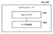
[ホストコンピュータの機能構成]
図3は、図1のホストコンピュータ101及び102の機能構成の一例を示すブロック図である。Webブラウザ301は、HTMLデータを解釈し、表示モジュール210に画面表示させるための描画処理を行い、キーボード等から受付けたユーザ操作に基づき、HTTP通信部302にHTTP要求コマンドを送信する。HTTP通信部302は、Webブラウザ301からの通信要求を受けて、NIC204を介してHTTPまたはHTTPSプロトコルを用いて、管理サーバ103と通信を行い、Webページの要求や、Webページデータの受信を行う。
[Functional configuration of the host computer]
FIG. 3 is a block diagram showing an example of the functional configuration of the
[管理サーバの機能構成]
図4は、図1の管理サーバ103の機能構成の一例を示すブロック図である。インタフェース部401は、図2のNIC204によりネットワーク104を介して、ホストコンピュータ101との通信を制御する。インタフェース部401は、ホストコンピュータ101及び102からのHTTPまたはHTTPSによるWebページへの要求があると、アクセス許可状態などを判定した後、HTMLデータを返信する。
[Functional configuration of Management Server]
FIG. 4 is a block diagram illustrating an example of a functional configuration of the
テナント情報管理部402は、サービスプロバイダテナントおよび顧客テナントに関する情報を保持する。さらに、テナント情報管理部402は、各サービスプロバイダの管理対象の顧客テナントに関する情報(顧客情報)を保持する。共有情報管理部403は、サービスプロバイダがどのサービスプロバイダに対してどの顧客テナントを共有しているかを示す共有情報を保持する。共有情報は、各サービスプロバイダが管理する管理情報の一部に該当する。例えば、特定のサービスプロバイダのみに管理される顧客テナント情報は管理情報であり、他のサービスプロバイダからも共有される顧客テナント情報は管理情報であり且つ共有情報でもある。
The tenant
顧客の管理を別のサービスプロバイダ(共有先)に対して共有させることにより、共有元及び共有先の複数のサービスプロバイダが1つの顧客を管理することができる。サービスプロバイダ間で共有元と共有先の関係がある場合、一般的に、共有元のサービスプロバイダは、共有先のサービスプロバイダよりも使用できる機能が多い。例えば、共有元サービスプロバイダは、共有関係の解除や、共有先サービスプロバイダが使用可能な機能の制限を行うことができる。本実施形態において、テナント管理システムに存在するテナント間は、上記のような共有関係により、階層構造を成している。 By sharing customer management with different service providers (shared destinations), a plurality of service providers of the sharing source and the shared destination can manage one customer. When there is a relationship between a sharing source and a sharing destination between service providers, in general, the sharing source service provider has more functions than the sharing destination service provider. For example, the sharing source service provider can cancel the sharing relationship and limit the functions that can be used by the sharing destination service provider. In this embodiment, tenants existing in the tenant management system have a hierarchical structure due to the above-described sharing relationship.
移管処理部404は、ユーザによりサービスプロバイダの移管が指示された場合に、移管元のサービスプロバイダが管理する情報を、移管先のサービスプロバイダに移管する処理を実行する。
When the transfer instruction of the service provider is instructed by the user, the
[サービスプロバイダテナント情報テーブル]
図5は、図4のテナント情報管理部402が管理するサービスプロバイダテナント情報テーブル500の一例を示す図である。サービスプロバイダテナント情報テーブル500は、システムに存在するサービスプロバイダテナントの一覧を示す。サービスプロバイダテナントID501は、サービスプロバイダテナントをシステム内で一意に識別するための識別情報(ID)である。サービスプロバイダテナント名502は、サービスプロバイダテナントID501で示されるサービスプロバイダテナントの名称を示す。サービスプロバイダテナント情報テーブル500の各設定値は、管理サーバ103の入力装置を介してユーザにより設定/変更可能である。また、サービスプロバイダテナント情報テーブル500は、例えばファイル名で区別可能にすることで、サービスプロバイダテナントごとに構成しても良い。
[Service Provider Tenant Information Table]
FIG. 5 is a diagram illustrating an example of the service provider tenant information table 500 managed by the tenant
[顧客テナント情報テーブル]
図6(a)は、図4のテナント情報管理部402が管理する顧客テナント情報テーブル600の一例を示す図である。顧客テナント情報テーブル600は、システムに存在する顧客テナントの一覧を示す。顧客テナントID601は、顧客テナントをシステム内で一意に識別するためのIDである。顧客テナント名602は、顧客テナントID601で示される顧客テナントの名称を示す。ライセンス付与サービスプロバイダテナントID603は、階層構造のルートに位置する共有情報とするためのライセンスを顧客テナントに付与したサービスプロバイダテナントIDを示す。
[Customer tenant information table]
FIG. 6A is a diagram illustrating an example of a customer tenant information table 600 managed by the tenant
顧客テナント情報テーブル600の各設定値は、管理サーバ103の入力装置を介してユーザにより設定/変更可能である。また、顧客テナント情報テーブル600は、例えばファイル名で区別可能にすることで、顧客テナントごとに構成しても良い。図6(b)は、本実施形態の移管処理が行われた後の顧客テナント情報テーブル600であり後述する。
Each setting value of the customer tenant information table 600 can be set / changed by the user via the input device of the
[管理顧客テナント情報テーブル]
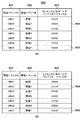
図7(a)は、図4のテナント情報管理部402が管理する管理顧客テナント情報テーブル700の一例を示す図である。管理顧客テナント情報テーブル700は、サービスプロバイダテーブルが管理する顧客テナントを示す一覧である。サービスプロバイダテナント701は、サービスプロバイダテナントをシステム内で一意に識別するためのIDである。管理顧客テナントID702は、顧客テナントをシステム内で一意に識別するためのIDである。図7(a)において、サービスプロバイダテナントID701で示されるサービスプロバイダは、各行で対応する顧客テナントID702で示される顧客を管理している。
[Management customer tenant information table]
FIG. 7A is a diagram illustrating an example of the management customer tenant information table 700 managed by the tenant
管理顧客テナント情報テーブル700の各設定値は、管理サーバ103の入力装置を介してユーザにより設定/変更可能である。また、管理顧客テナント情報テーブル700は、例えばファイル名で区別可能にすることで、サービスプロバイダテナントごとに構成しても良い。図7(b)は、本実施形態の移管処理が行われた後の管理顧客テナント情報テーブル700であり後述する。
Each setting value of the management customer tenant information table 700 can be set / changed by the user via the input device of the
[共有情報テーブル]
図8(a)は、図4の共有情報管理部403が管理する共有情報テーブル800の一例を示す図である。顧客テナントID801は、顧客テナントをシステム内で一意に識別するためのIDである。共有元サービスプロバイダテナントID802は、各行で対応する顧客テナントIDの顧客テナントを管理するサービスプロバイダテナントを識別するためのIDである。共有先サービスプロバイダテナントID803は、共有元サービスプロバイダテナントから共有を許可されたサービスプロバイダを識別するためのIDである。例えば、行804では、共有元サービスプロバイダテナントのS000Bは、顧客テナントC0003の管理を、共有先サービスプロバイダテナントのS000Xに共有している。
[Shared information table]
FIG. 8A is a diagram showing an example of the shared information table 800 managed by the shared
共有情報テーブル800の各設定値は、管理サーバ103の入力装置を介してユーザにより設定/変更可能である。図8(b)及び図9は、本実施形態の移管処理が行われた後の共有情報テーブル800であり後述する。
Each setting value of the shared information table 800 can be set / changed by the user via the input device of the
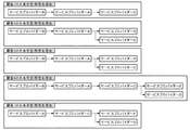
図10は、図8(a)に示す共有状態を概念的に表した図である。例えば、図10の顧客3は図8(a)のC0003に対応し、サービスプロバイダBはS000Bに対応し、サービスプロバイダXはS000Xに対応している。つまり、図8(a)において、顧客テナントID801がC0003である顧客テナントは、共有元サービスプロバイダテナントS000Bから共有先サービスプロバイダテナントS000Xに共有される。そして、さらに、サービスプロバイダテナントS000Xは、共有元サービスプロバイダテナントとして、サービスプロバイダテナントS000Cに共有している。その共有状態を表した図が、図10の「顧客3の共有状態」である。図10の他の顧客についても、図8(a)の記載に従う。なお、図10では、顧客テナントは顧客と略記され、サービスプロバイダテナントはサービスプロバイダと略記されている。図11及び図12は、本実施形態の移管処理が行われた後の共有状態であり後述する。
FIG. 10 is a diagram conceptually showing the shared state shown in FIG. For example,
[サービスプロバイダ移管設定画面]
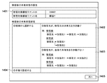
図13(a)は、サービスプロバイダの移管設定画面の一例を示す図である。サービスプロバイダの移管設定画面は、ホストコンピュータ101でサービスプロバイダの移管についての設定と実行の操作を受付けるための設定画面である。サービスプロバイダの移管設定画面では、移管元のサービスプロバイダ1301、移管先のサービスプロバイダ1302、移管対象の顧客1303を設定(指定)可能である。ユーザがそれらの情報を設定して移管ボタン1304を押下すると、設定内容がHTTPリクエストに設定され、管理サーバ103に送信される。
[Service Provider Transfer Settings Screen]
FIG. 13A is a diagram illustrating an example of a transfer setting screen of a service provider. The service provider transfer setting screen is a setting screen for accepting setting and execution operations for the service provider transfer on the
管理サーバ103では、インタフェース部401がHTTPリクエストを受信し、入力情報に問題がないかをチェックする。ここで、移管先のサービスプロバイダの間接的な共有先が移管元のサービスプロバイダとなっている顧客が存在する場合は、図13(b)の画面を表示する。例えば、図13(b)の「移管先が、移管元の共有先を引き継ぐ」項目に表示されているように、移管先から別販社1に共有され、さらに移管元に共有されている場合である。また、移管元のサービスプロバイダの間接的な共有先が移管先のサービスプロバイダとなっている顧客が存在する場合は、図14の画面を表示する。例えば、図14の「移管先が、移管元の共有先を引き継ぐ」項目に表示されているように、移管元から別販社1に共有され、さらに移管先に共有されている場合である。上記以外の場合は、インタフェース部401は、移管処理部404に移管処理リクエストを送信する。
In the
図13(b)は、移管先のサービスプロバイダの間接的な共有先が移管元のサービスプロバイダとなっている顧客が存在する場合に表示される、移管後の共有状態設定画面の一例を示す図である。移管先サービスプロバイダと移管元サービスプロバイダに間接的な共有関係がある場合、移管先サービスプロバイダはどのサービスプロバイダい共有を許可するかが不明となり、移管後の共有状態が一意に決められない。 FIG. 13B is a diagram showing an example of a shared state setting screen after transfer that is displayed when there is a customer whose indirect sharing destination of the transfer destination service provider is the transfer source service provider. It is. When there is an indirect sharing relationship between the transfer destination service provider and the transfer source service provider, it is unclear which service provider allows the transfer destination service provider to share, and the shared state after transfer cannot be uniquely determined.
そのため、本実施形態では、図13(b)に示すように、移管後の共有状態の候補を表示することにより、移管前にユーザに選択可能とさせる。移管後の共有状態設定画面では、顧客1305の移管後の共有状態について、移管先サービスプロバイダが移管元サービスプロバイダの移管前の共有先を引き継ぐ(適用する)ことを設定する候補1306か、または、引き継がないことを設定する候補1307を選択可能である。また、移管後の共有状態について、候補1306や候補1307ではない共有状態をユーザが設定したい場合は、手動で設定するための候補1308を選択可能である。その場合、ユーザは、所望の共有状態を設定することができる。
Therefore, in this embodiment, as shown in FIG. 13B, the sharing state candidates after the transfer are displayed so that the user can select them before the transfer. In the shared state setting screen after transfer, regarding the shared state after the transfer of the
ユーザがそれらの情報を設定して、次へボタン1309を押下すると、設定内容がHTTPリクエストに設定され、管理サーバ103に送信される。管理サーバ103では、インタフェース部401がHTTPリクエストを受信し、入力情報に問題がないかをチェックする。ここで、移管先サービスプロバイダと移管元サービスプロバイダに間接的な共有関係がある顧客が存在する場合は、再び、図13(b)、若しくは、図14の画面を表示する。上記以外の場合は、インタフェース部401は、移管処理部404に移管処理リクエストを送信する。
When the user sets such information and presses the next button 1309, the setting contents are set in the HTTP request and transmitted to the
図14は、移管元のサービスプロバイダの間接的な共有先が移管先のサービスプロバイダとなっている顧客が存在する場合に表示される、移管後の共有状態設定画面の一例を示す図である。図13(b)と同様に、移管先サービスプロバイダと移管元サービスプロバイダに間接的な共有関係がある場合、移管先サービスプロバイダはどのサービスプロバイダから共有を許可されるかが不明となり、移管後の共有状態が一意に決められない。 FIG. 14 is a diagram illustrating an example of a shared state setting screen after transfer that is displayed when there is a customer whose indirect sharing destination of the transfer source service provider is the transfer destination service provider. Similarly to FIG. 13B, when there is an indirect sharing relationship between the transfer destination service provider and the transfer source service provider, it is unclear from which service provider the transfer destination service provider is allowed to share. The sharing status cannot be determined uniquely.
そのため、本実施形態では、図14に示すように、移管後の共有状態の候補を表示することにより、移管前にユーザに選択可能とさせる。移管後の共有状態設定画面では、顧客1401の移管後の共有状態について、移管先サービスプロバイダが自身の移管前の共有先を引き継ぐことを設定する候補1402、または、引き継がないことを設定する候補1403を選択可能である。また、移管後の共有状態について、候補1402や候補1403ではない共有状態をユーザが設定したい場合は、手動で設定するための候補1404を選択可能である。その場合、ユーザは、所望の共有状態を設定することができる。
Therefore, in the present embodiment, as shown in FIG. 14, by displaying the shared state candidates after the transfer, the user can select them before the transfer. On the shared status setting screen after transfer, regarding the shared status after the transfer of the
ユーザがそれらの情報を設定して、次へボタン1405を押下すると、設定内容がHTTPリクエストに設定され、管理サーバ103に送信される。管理サーバ103では、インタフェース部401がHTTPリクエストを受信し、入力情報に問題がないかをチェックする。ここで、移管先サービスプロバイダと移管元サービスプロバイダに間接的な共有関係がある顧客が存在する場合は、再び、図13(b)、若しくは、図14の画面を表示する。上記以外の場合は、インタフェース部401は、移管処理部404に移管処理リクエストを送信する。移管処理部404は、移管処理リクエストを受信すると、以下の移管処理を実行する。
When the user sets such information and presses the
[移管処理]
図15は、図4の移管処理部404が実行するサービスプロバイダの移管処理の手順を示すフローチャートである。図1の管理サーバ103が情報処理装置として図15の処理を行う。管理サーバ103は、図13のサービスプロバイダの移管設定画面においてサービスプロバイダの移管設定が行われたときに本処理を実行する。図15の各処理は、例えば、CPU201がHD211やROM202等より制御プログラムをRAM203にロードして実行することにより実現される。
[Transfer processing]
FIG. 15 is a flowchart showing a procedure of a service provider transfer process executed by the
移管処理を開始すると、S1501において、移管処理部404は、管理顧客テナント情報テーブル700に保管されている共有情報を参照し、移管元のサービスプロバイダが管理している管理顧客テナント情報を取得する。次に、S1502において、移管処理部404は、管理顧客テナント情報テーブル700に保管されている共有情報を参照し、移管先のサービスプロバイダが管理している管理顧客テナント情報を取得する。
When the transfer process is started, in S1501, the
次に、S1503において、移管処理部404は、共有情報の変更処理を行う。S1503の処理の詳細は後述する。そして、S1504において、移管処理部404は、管理顧客テナント情報の変更処理を行い、本処理を終了する。S1504の処理の詳細は後述する。
In step S1503, the
[共有情報の変更処理]
図16は、図15のS1503の共有情報の変更処理の詳細な手順を示すフローチャートである。本処理による共有情報の変更により、サービスプロバイダ移管後の共有状態が適切な状態となる。
[Change shared information]
FIG. 16 is a flowchart showing a detailed procedure of shared information change processing in S1503 of FIG. By changing the shared information by this process, the shared state after the transfer of the service provider becomes an appropriate state.
共有情報の変更処理を開始すると、S1601において、移管処理部404は、管理情報のうち、共有情報テーブル800に保管されている共有情報を参照して、移管元サービスプロバイダが共有元サービスプロバイダまたは共有先サービスプロバイダである共有情報を特定して取得する。以降、移管処理部404は、S1601で取得した共有情報の1件毎に、S1602〜S1610までの処理を繰り返す。
When the shared information change process is started, in S1601, the
S1603において、移管処理部404は、処理中の共有情報について、共有対象の顧客テナントが移管先サービスプロバイダの管理顧客テナントに存在するか否かを判定する。ここで、共有対象の顧客テナントが移管先サービスプロバイダの管理顧客テナントに存在すると判定された場合はS1604に進み、共有対象の顧客テナントが移管先サービスプロバイダの管理顧客テナントに存在しないと判定された場合はS1607に進む。
In step S1603, the
S1604において、移管処理部404は、処理中の共有情報について、移管元サービスプロバイダが共有元サービスプロバイダであるか否かを判定する。ここで、移管元サービスプロバイダが共有元サービスプロバイダであると判定された場合はS1605に進み、移管元サービスプロバイダが共有元サービスプロバイダでないと判定された場合はS1606に進む。ここで、移管元サービスプロバイダが共有元サービスプロバイダではないと判定されたということは、移管元サービスプロバイダが共有先サービスプロバイダであるということになる。
In step S1604, the
S1605において、移管処理部404は、移管元サービスプロバイダが共有元サービスプロバイダである共有情報の変更処理を行う。S1605の処理の詳細は後述する。また、S1606において、移管処理部404は、移管元サービスプロバイダが共有先サービスプロバイダである共有情報の変更処理を行う。S1606の処理の詳細は後述する。また、S1607において、移管処理部404は、移管先サービスプロバイダが管理していない顧客についての共有情報の変更処理を行う。S1607処理の詳細は後述する。
In step S1605, the
S1608において、移管処理部404は、S1605、S1606、S1607の共有情報の変更処理によって、移管先サービスプロバイダが共有のルート(共有関係における再上位の位置)になったか否かを判定する。ここで、共有のルートとは、共有対象の顧客テナントについて、移管先サービスプロバイダに対して共有しているサービスプロバイダが存在しない状態である。S1608で移管先サービスプロバイダが共有のルートになったと判定された場合はS1609に進み、移管先サービスプロバイダが共有のルートになっていないと判定された場合はS1610に進む。
In S1608, the
S1609において、移管処理部404は、処理中の共有情報の共有対象の顧客テナントについて、ライセンス付与サービスプロバイダテナントID603を移管先サービスプロバイダのテナントIDに変更する。これは、サービスプロバイダ移管後に、顧客にライセンス付与したサービスプロバイダが存在しなくなることを防ぐために行う。
In step S <b> 1609, the
S1610において、移管処理部404は、S1602〜S1610の処理を行っていない共有情報があるか否かを判定する。ここで、S1602〜S1610の処理を行っていない共有情報があると判定された場合はS1602からの処理を繰り返す。一方、S1602〜S1610の処理を行っていない共有情報がないと判定された場合は、図16の処理を終了する。
In step S1610, the
[共有情報の変更処理(移管元プロバイダが共有元プロバイダである場合)]
図17は、図16のS1605の処理の詳細な手順を示すフローチャートである。本処理では、移管元サービスプロバイダが共有元サービスプロバイダである共有情報の変更を行う。
[Shared information change processing (when the transfer source provider is the share source provider)]
FIG. 17 is a flowchart showing a detailed procedure of the processing in S1605 of FIG. In this process, the transfer source service provider changes the shared information that is the share source service provider.
共有情報の変更処理を開始すると、S1701において、移管処理部404は、処理中の共有情報について、共有先サービスプロバイダが移管先サービスプロバイダであるか否かを判定する。ここで、共有先サービスプロバイダが移管先サービスプロバイダであると判定された場合はS1702に進み、共有先サービスプロバイダが移管先サービスプロバイダでないと判定された場合はS1703に進む。
When the shared information change process is started, in S1701, the
S1702において、移管処理部404は、処理中の共有情報について、共有情報テーブルから削除し、図17の処理を終了する。S1703において、移管処理部404は、共有情報テーブルに保管されている共有情報を参照し、処理中の共有情報の共有先方向の共有情報を全て取得する。ここで、共有先方向とは、例えば、サービスプロバイダAが共有元であってサービスプロバイダBを共有先とし、かつ、サービスプロバイダBが共有元であってサービスプロバイダCを共有先としている場合、Aからの共有先方向とは、B及びCとなる。つまり、共有先方向の共有情報とは、共有関係の共有先を辿るつながりにおいて含まれる情報をいう。
In S1702, the
S1704において、移管処理部404は、S1703で取得した共有情報に基づいて、共有先方向に移管先サービスプロバイダが存在するか否かを判定する。ここで、共有先方向に移管先サービスプロバイダが存在すると判定された場合はS1705に進み、共有先方向に移管先サービスプロバイダが存在しないと判定された場合はS1713に進む。
In S1704, the
S1705において、移管処理部404は、処理中の共有情報について、共有元サービスプロバイダテナントID802を移管先サービスプロバイダのテナントIDに変更する。以降、移管処理部404は、S1703で取得した共有先方向の共有情報の1件毎に、S1706〜S1712までの処理を繰り返す。
In S1705, the
S1707において、移管処理部404は、処理中の共有先方向の共有情報について、共有先サービスプロバイダが移管先サービスプロバイダであるか否かを判定する。ここで、共有先サービスプロバイダが移管先サービスプロバイダであると判定された場合はS1708に進み、共有先サービスプロバイダが移管先サービスプロバイダでないと判定された場合はS1709に進む。
In step S <b> 1707, the
S1708において、移管処理部404は、処理中の共有先方向の共有情報について、共有情報テーブルから削除する。S1709において、移管処理部404は、処理中の共有先方向の共有情報について、共有元サービスプロバイダが移管先サービスプロバイダであるか否かを判定する。ここで、共有元サービスプロバイダが移管先サービスプロバイダであると判定された場合はS1710に進み、共有元サービスプロバイダが移管先サービスプロバイダでないと判定された場合はS1712に進む。
In step S1708, the
S1710において、移管処理部404は、移管後の共有状態設定画面において、移管後の共有状態として、設定1306若しくは設定1402が選択されているか否かを判定する。つまり、S1710では、移管先サービスプロバイダが移管元サービスプロバイダ/自身の共有先を引き継ぐか否かを、移管後の共有状態設定画面の設定に基づいて判定する。ここで、移管後の共有状態として、設定1306若しくは設定1402が選択されていると判定された場合はS1712に進む。一方、移管後の共有状態として、設定1306若しくは設定1402が選択されていないと判定された場合はS1711に進む。設定1306若しくは設定1402が選択されていないと判定された場合とは、つまり、移管後の共有状態として、設定1307若しくは設定1403が選択されているということである。
In step S <b> 1710, the
S1711において、移管処理部404は、処理中の共有情報について、共有元サービスプロバイダテナントID802を、共有関係上の一階層上位のサービスプロバイダのテナントIDに変更する。
In step S <b> 1711, the
S1712において、移管処理部404は、S1706〜S1712の処理を行っていない共有先方向の共有情報があるか否かを判定する。ここで、S1706〜S1712の処理を行っていない共有先方向の共有情報があると判定された場合はS1706からの処理を繰り返す。一方、S1706〜S1712の処理を行っていない共有先方向の共有情報がないと判定された場合は、図17の処理を終了する。
In step S1712, the
S1713において、移管処理部404は、共有情報テーブルに保管されている共有情報を参照し、処理中の共有情報の共有元方向の共有情報を全て取得する。ここで、共有元方向とは、例えば、サービスプロバイダBが共有元であってサービスプロバイダAを共有先とし、かつ、サービスプロバイダCが共有元であってサービスプロバイダBを共有先としている場合、Aからの共有元方向とは、B及びCとなる。つまり、共有元方向の共有情報とは、共有関係の共有元を辿るつながりにおいて含まれる情報をいう。
In step S <b> 1713, the
S1714において、移管処理部404は、S1713で取得した共有情報に基づいて、共有元方向に移管先サービスプロバイダが存在するか否かを判定する。ここで、共有元方向に移管先サービスプロバイダが存在すると判定された場合はS1715に進み、共有元方向に移管先サービスプロバイダが存在しないと判定された場合はS1716に進む。
In S1714, the
S1715において、移管処理部404は、移管後の共有状態設定画面において、移管後の共有状態として、設定1306若しくは設定1402が選択されているか否かを判定する。つまり、S1715では、移管先サービスプロバイダが移管元サービスプロバイダ/自身の共有先を引き継ぐか否かを、移管後の共有状態設定画面の設定に基づいて判定する。ここで、移管後の共有状態として、設定1306若しくは設定1402が選択されていると判定された場合はS1716に進む。一方、移管後の共有状態として、設定1306若しくは設定1402が選択されていないと判定された場合はS1717に進む。設定1306若しくは設定1402が選択されていないと判定された場合とは、つまり、移管後の共有状態として、設定1307若しくは設定1403が選択されているということである。
In step S1715, the
S1716で、移管処理部404は、処理中の共有情報について、共有元サービスプロバイダテナントID802を移管先サービスプロバイダのテナントIDに変更し、図17の処理を終了する。また、S1717において、移管処理部404は、処理中の共有情報について、共有元サービスプロバイダテナントID802を、共有関係上で一階層上位のサービスプロバイダのテナントIDに変更し、図17の処理を終了する。
In step S1716, the
[共有情報の変更処理(移管元プロバイダが共有先プロバイダである場合)]
図18は、図16のS1606の処理の詳細な手順を示すフローチャートである。本処理では、移管元サービスプロバイダが共有先サービスプロバイダである共有情報の変更を行う。
[Shared information change processing (when the transfer source provider is the shared provider)]
FIG. 18 is a flowchart showing a detailed procedure of the processing of S1606 in FIG. In this process, the transfer source service provider changes the shared information that is the share destination service provider.
共有情報の変更処理を開始すると、S1801において、移管処理部404は、共有情報テーブル800に保管されている共有情報を参照し、処理中の共有情報の共有元方向の共有情報を全て取得する。
When the shared information change process is started, in step S1801, the
S1802において、移管処理部404は、S1801で取得した共有情報に基づいて、共有元方向に移管先サービスプロバイダが存在するか否かを判定する。ここで、共有元方向に移管先サービスプロバイダが存在すると判定された場合はS1803に進み、共有元方向に移管先サービスプロバイダが存在しないと判定された場合はS1804に進む。
In S1802, the
S1803において、移管処理部404は、処理中の共有情報について、共有情報テーブルから削除し、図18の処理を終了する。また、S1804において、移管処理部404は、処理中の共有情報について、共有先サービスプロバイダテナントID802を移管先サービスプロバイダのテナントIDに変更し、図18の処理を終了する。
In step S1803, the
[共有情報の変更処理(移管先プロバイダにより管理されていない顧客テナントの場合)]
図19は、図16のS1607の処理の詳細な手順を示すフローチャートである。本処理では、移管先サービスプロバイダにより管理されていない顧客テナントについて、共有情報の変更処理を行う。
[Shared information change processing (for customer tenants not managed by the transfer destination provider)]
FIG. 19 is a flowchart showing a detailed procedure of the processing of S1607 in FIG. In this process, the shared information is changed for the customer tenant that is not managed by the transfer destination service provider.
共有情報の変更処理を開始すると、S1901において、移管処理部404は、処理中の共有情報について、移管元サービスプロバイダが共有元サービスプロバイダであるか否かを判定する。ここで、移管元サービスプロバイダが共有元サービスプロバイダであると判定された場合はS1902に進み、移管元サービスプロバイダが共有元サービスプロバイダではないと判定された場合はS1503に進む。移管元サービスプロバイダが共有元サービスプロバイダではないと判定した共有情報とは、移管元サービスプロバイダが共有先サービスプロバイダである共有情報である。
When the shared information changing process is started, in S1901, the
S1902において、移管処理部404は、処理中の共有情報について、共有元サービスプロバイダテナントID802を移管先サービスプロバイダのテナントIDに変更し、図19の処理を終了する。また、S1903において、移管処理部404は、処理中の共有情報について、共有先サービスプロバイダテナントID802を移管先サービスプロバイダのテナントIDに変更し、図19の処理を終了する。
In S1902, the
[管理顧客テナント情報の変更処理]
図20は、図15のS1504の処理の詳細な手順を示すフローチャートである。本処理では、管理顧客テナント情報テーブル700に保管されている管理顧客テナント情報について、サービスプロバイダの移管に伴う変更処理を行う。
[Management customer tenant information change processing]
FIG. 20 is a flowchart showing a detailed procedure of the process of S1504 of FIG. In this process, the management customer tenant information stored in the management customer tenant information table 700 is changed according to the transfer of the service provider.
管理顧客テナント情報の変更処理を開始すると、S2001において、移管処理部404は、S1501で取得した移管元サービスプロバイダの管理顧客テナント情報の1件毎に、S2001〜S2005までの処理を繰り返す。ここで、処理対象となる管理顧客テナント情報とは、S1601の処理の対象とならなかったもの(S1601の処理対象の管理情報以外の管理情報)であり、つまり、移管元サービスプロバイダが共有元サービスプロバイダと共有先サービスプロバイダのいずれでもない共有情報である。
When the management customer tenant information changing process is started, in S2001, the
S2002において、移管処理部404は、処理対象の管理顧客テナント情報について、S1502で取得した移管先サービスプロバイダの管理顧客テナント情報に基づいて、移管先サービスプロバイダの管理する顧客テナントであるか否かを判定する。ここで、移管先サービスプロバイダの管理する顧客テナントであると判定された場合はS2003に進み、移管先サービスプロバイダの管理する顧客テナントでないと判定された場合はS2004に進む。
In S2002, the
S2003において、移管処理部404は、処理対象の管理顧客テナント情報について、管理顧客テナント情報テーブルから削除する。また、S2004において、移管処理部404は、処理対象の管理顧客テナント情報について、サービスプロバイダテナントID701を移管先サービスプロバイダのテナントIDに変更する。
In step S2003, the
S2005で、移管処理部404は、S2001〜S2005の処理を行っていない管理顧客テナント情報があるか否かを判定する。ここで、S2001〜S2005の処理を行っていない管理顧客テナント情報があると判定された場合はS2001からの処理を繰り返す。一方、S2001〜S2005の処理を行っていない管理顧客テナント情報がないと判定された場合は、図20の処理を終了する。
In step S2005, the
[顧客テナント情報テーブル(移管処理後)]
図6(b)は、図6(a)の顧客テナント情報テーブル600の移管処理後の状態を示す図である。ここで、移管元サービスプロバイダは、サービスプロバイダX(サービスプロバイダテナントIDはS000X)とする。また、移管先サービスプロバイダは、サービスプロバイダA(サービスプロバイダテナントIDはS000A)とする。図6(b)に示すように、顧客テナント情報604と605は、図16のS1609の処理により、ライセンス付与サービスプロバイダテナントID603が移管先のサービスプロバイダIDに変更されている。
[Customer tenant information table (after transfer processing)]
FIG. 6B is a diagram showing a state after the transfer process of the customer tenant information table 600 of FIG. Here, the transfer source service provider is assumed to be service provider X (service provider tenant ID is S000X). The transfer destination service provider is assumed to be service provider A (service provider tenant ID is S000A). As shown in FIG. 6B, in the
[管理顧客テナント情報テーブル(移管処理後)]
図7(b)は、図7(a)の管理顧客テナント情報テーブル700の移管処理後の状態を示す図である。管理顧客テナント情報703と704は、図20のS2004の処理により、サービスプロバイダテナントID701が移管先のサービスプロバイダIDに変更されている。また、管理顧客テナント情報705〜708は、S2003の処理により、削除されている。
[Managed customer tenant information table (after transfer processing)]
FIG. 7B is a diagram illustrating a state after the transfer process of the management customer tenant information table 700 of FIG. In the management
[共有情報テーブル(移管処理後)]
図8(b)及び図9は、図8(a)の共有情報テーブル800の移管処理後の状態を示す図である。図8(b)は、移管後の共有状態設定画面において、移管後の共有状態として、設定1306若しくは設定1402が選択された場合の移管処理後の状態を示す図である。図9は、移管後の共有状態として、設定1307若しくは設定1403が選択された場合の移管処理後の状態を示す図である。図9は、共有情報815において図8と異なる。
[Shared information table (after transfer processing)]
FIGS. 8B and 9 are diagrams showing the state after the transfer process of the shared information table 800 of FIG. FIG. 8B is a diagram illustrating a state after the transfer process when setting 1306 or setting 1402 is selected as the shared state after transfer on the shared state setting screen after transfer. FIG. 9 is a diagram illustrating a state after the transfer process when the setting 1307 or the setting 1403 is selected as the shared state after the transfer. FIG. 9 differs from FIG. 8 in the shared
図8(b)に示すように、共有情報804は、図19のS1903の処理により、共有先サービスプロバイダテナントID803が移管先のサービスプロバイダIDに変更されている。共有情報805は、図19のS1902の処理により、共有元サービスプロバイダテナントID802が移管先のサービスプロバイダIDに変更されている。
As shown in FIG. 8B, in the shared
共有情報806は、図18のS1803の処理により、削除されている。共有情報807は、図17のS1716の処理により、共有元サービスプロバイダテナントID802が移管先のサービスプロバイダIDに変更されている。共有情報808は、図18のS1804の処理により、共有先サービスプロバイダテナントID803が移管先のサービスプロバイダIDに変更されている。
The shared
共有情報809は、図17のS1702の処理により、削除されている。共有情報810は、図17のS1716の処理により、共有元サービスプロバイダテナントID802が移管先のサービスプロバイダIDに変更されている。
The shared
共有情報811は、図18のS1803の処理により、削除されている。共有情報812は、図17のS1716の処理により、共有元サービスプロバイダテナントID802が移管先のサービスプロバイダIDに変更されている。共有情報813は、図17のS1705の処理により、共有元サービスプロバイダテナントID802が移管先のサービスプロバイダIDに変更されている。共有情報814は、図17のS1708の処理により、削除されている。共有情報815は、図8(b)では、S1710で「移管元サービスプロバイダテナント/自身の共有先を引き継ぐ」と判定されるので、内容は変更されない。一方、図9では、図17のS1711の処理により、共有元サービスプロバイダテナントID802がサービスプロバイダAの上位に位置するサービスプロバイダCのIDに変更されている。
The shared
図11は、図8(b)の共有情報により表わされる、移管後の顧客の共有状態を示す図である。図12は、移管後の共有状態設定画面において、移管後の共有状態として、設定1307若しくは設定1403が選択された(移管先が共有先を引き継がない)場合の移管処理後の状態を示す図である。まず、図11を参照しながら、移管先が共有先を引き継ぐ場合について説明する。 FIG. 11 is a diagram illustrating the shared state of the customer after the transfer, which is represented by the shared information in FIG. 8B. FIG. 12 is a diagram showing a state after the transfer process when the setting 1307 or the setting 1403 is selected as the sharing state after the transfer on the sharing state setting screen after the transfer (the transfer destination does not take over the sharing destination). is there. First, a case where the transfer destination takes over the sharing destination will be described with reference to FIG.
図11の顧客3について、図8(b)に示すように、共有情報804は、図19のS1903の処理により、共有先サービスプロバイダテナントID803が移管先のサービスプロバイダIDに変更されている。これは、図11の顧客3の共有状態に示すように、サービスプロバイダBの共有先がサービスプロバイダX(移管元)からサービスプロバイダA(移管先)に変更されていることに対応する。
For the
図8(b)に示すように、共有情報805は、図19のS1902の処理により、共有元サービスプロバイダテナントID802が移管先のサービスプロバイダIDに変更されている。これは、図11の顧客3の共有状態に示すように、サービスプロバイダCの共有元がサービスプロバイダX(移管元)からサービスプロバイダA(移管先)に変更されていることに対応する。
As shown in FIG. 8B, in the shared
図11の顧客4について、図8(b)に示すように、共有情報806(AからX)は、図18のS1803の処理により、削除されている。これは、図11の顧客4の共有状態に示すように、サービスプロバイダX(移管元)が削除されていることに対応する。また、図8(b)に示すように、共有情報807は、図17のS1717の処理により、共有元サービスプロバイダテナントID802が変更されている。図11では、移管先は共有先を引き継ぐので、サービスプロバイダAの共有先がサービスプロバイダDとなる。
For the customer 4 in FIG. 11, as shown in FIG. 8B, the shared information 806 (A to X) has been deleted by the processing of S1803 in FIG. This corresponds to the fact that the service provider X (transfer source) has been deleted, as shown in the sharing state of the customer 4 in FIG. Also, as shown in FIG. 8B, in the shared
図11の顧客5について、図8(b)に示すように、共有情報808は、図18のS1804の処理により、共有先サービスプロバイダテナントID803が移管先のサービスプロバイダIDに変更されている。これは、図11の顧客5の共有状態に示すように、サービスプロバイダBの共有先がサービスプロバイダX(移管元)からサービスプロバイダA(移管先)に変更されていることに対応する。また、図8(b)に示すように、共有情報809は、S1702の処理により、削除されている。これは、図11の顧客5の共有状態に示すように、サービスプロバイダX(移管元)が削除されていることに対応する。また、図8(b)に示すように、共有情報810は、図17のS1716の処理により、共有元サービスプロバイダテナントID802が移管先のサービスプロバイダIDに変更されている。これは、図11の顧客5の共有状態に示すように、サービスプロバイダCの共有元がサービスプロバイダX(移管元)からサービスプロバイダA(移管先)に変更されていることに対応する。顧客5については、結果、サービスプロバイダAは、サービスプロバイダDとCに対して共有することになる。
For the customer 5 in FIG. 11, as shown in FIG. 8B, in the shared
顧客6について、図8(b)に示すように、共有情報811は、図18のS1803の処理により、削除されている。これは、図11の顧客6の共有状態に示すように、サービスプロバイダX(移管元)が削除されていることに対応する。また、図8(b)に示すように、共有情報812は、図17のS1717の処理により、共有元サービスプロバイダテナントID802が変更されている。これは、図11の顧客6の共有状態に示すように、サービスプロバイダEの共有元がサービスプロバイダX(移管元)からサービスプロバイダA(移管先)に変更されていることに対応する。顧客6については、結果、サービスプロバイダAは、サービスプロバイダCとEに対して共有することになる。
For the
顧客7について、図8(b)に示すように、共有情報813は、図17のS1705の処理により、共有元サービスプロバイダテナントID802が移管先のサービスプロバイダに変更されている。これは、図11の顧客7の共有状態に示すように、サービスプロバイダCの共有元がサービスプロバイダX(移管元)からサービスプロバイダA(移管先)に変更されていることに対応する。図8(b)に示すように、共有情報814は、図17のS1708の処理により、削除されている。つまり、サービスプロバイダCがサービスプロバイダAから共有されてさらにサービスプロバイダAに対して共有することになってしまうので、サービスプロバイダCからサービスプロバイダAへの共有関係は削除するということである。顧客7については、結果、サービスプロバイダAは、サービスプロバイダCとEに対して共有することになる。また、図8(b)に示すように、共有情報815は、サービスプロバイダAがサービスプロバイダEに対して共有するという関係は変わらない。
As for the customer 7, as shown in FIG. 8B, in the shared
次に、図12を参照しながら、移管先が共有先を引き継がない場合について図11と異なる点について説明する。図12の顧客6の共有状態に示すように、図11と異なり、サービスプロバイダEの共有元は、サービスプロバイダAではなくサービスプロバイダCである。図11の場合、移管元サービスプロバイダXの共有先サービスプロバイダEは、移管先サービスプロバイダAに引き継がれる。一方、図12の場合、移管元サービスプロバイダXの共有先サービスプロバイダEは、移管先サービスプロバイダAの共有関係上のさらに上位に位置するサービスプロバイダCに引き継がれるので、図12に示すような共有状態となる。
Next, with reference to FIG. 12, the difference from FIG. 11 when the transfer destination does not take over the sharing destination will be described. As shown in the sharing state of the
図12の顧客7の共有状態に示すように、図11と異なり、サービスプロバイダEの共有元は、サービスプロバイダAではなくサービスプロバイダCである。図11の場合、図10で移管元サービスプロバイダXより下位の共有関係は、移管先サービスプロバイダAに引き継がれる。一方、図12の場合、移管先サービスプロバイダAの共有先サービスプロバイダEは、移管先サービスプロバイダAの共有関係上のさらに上位に位置するサービスプロバイダCに引き継がれるので、図12に示すような共有状態となる。 As shown in the sharing state of the customer 7 in FIG. 12, unlike FIG. 11, the sharing source of the service provider E is not the service provider A but the service provider C. In the case of FIG. 11, the sharing relationship lower than the transfer source service provider X in FIG. 10 is taken over by the transfer destination service provider A. On the other hand, in the case of FIG. 12, the sharing destination service provider E of the transfer destination service provider A is handed over to the service provider C positioned higher in the sharing relationship of the transfer destination service provider A, so that the sharing as shown in FIG. It becomes a state.
本発明は、以下の処理を実行することによっても実現される。即ち、上述した実施形態の機能を実現するソフトウェア(プログラム)を、ネットワーク又は各種記憶媒体を介してシステム或いは装置に供給し、そのシステム或いは装置のコンピュータ(またはCPUやMPU等)がプログラムを読み出して実行する処理である。 The present invention is also realized by executing the following processing. That is, software (program) that realizes the functions of the above-described embodiments is supplied to a system or apparatus via a network or various storage media, and a computer (or CPU, MPU, or the like) of the system or apparatus reads the program. It is a process to be executed.
101、102 ホストコンピュータ、103 管理サーバ、104 ネットワーク、201 CPU 101, 102 Host computer, 103 Management server, 104 Network, 201 CPU
Claims (7)
前記複数のテナントのうち、テナント間での移管の対象となる管理情報を管理する第1のテナントを指定する第1の指定手段と、
前記第1の指定手段により指定された前記第1のテナントからの前記移管の対象となる管理情報の移管先となる第2のテナントを指定する第2の指定手段と、
前記第1のテナントで管理される管理情報のうち、他のテナントと共有されている管理情報を、当該管理情報についての共有関係に従って特定する特定手段と、
前記第1のテナントで管理される管理情報のうち、前記特定手段により特定された管理情報以外の管理情報を前記第2のテナントに移管する移管手段と、
前記特定手段により特定された管理情報についての共有関係を、前記移管手段による移管後に構成される新たな階層構造に従って、前記第2のテナントと該第2のテナントの上位または下位の階層のテナントとで共有することを示す共有関係に変更する変更手段と、を備え、
前記変更手段によって、前記特定手段により特定された管理情報についての共有関係が、前記移管手段による移管後に構成される新たな階層構造に従って、前記第2のテナントと該第2のテナントの上位または下位の階層のテナントとで共有することを示す共有関係に変更されることで、前記特定手段により特定された管理情報は、前記第2のテナントに移管される、
ことを特徴とする管理システム。 A management system that manages management information using a plurality of tenants having a hierarchical structure,
A first designation unit for designating a first tenant that manages management information to be transferred among tenants among the plurality of tenants;
Second designation means for designating a second tenant as a transfer destination of management information to be transferred from the first tenant specified by the first specification means;
Among the management information managed by the first tenant, specifying means for identifying management information shared with other tenants according to a sharing relationship for the management information;
Of the management information managed by the first tenant, transfer means for transferring management information other than the management information specified by the specifying means to the second tenant;
In accordance with a new hierarchical structure configured after the transfer by the transfer means, the second tenant and the tenant of the upper or lower hierarchy of the second tenant are shared with the management information specified by the specifying means. And changing means for changing to a sharing relationship indicating that sharing is performed at
According to the new hierarchical structure configured after the transfer by the transfer unit, the sharing relationship for the management information specified by the specifying unit by the changing unit is higher or lower than the second tenant and the second tenant. The management information specified by the specifying means is transferred to the second tenant by being changed to a sharing relationship indicating sharing with the tenant of the hierarchy of
Management system characterized by that.
前記変更手段は、前記特定手段により特定された管理情報についての共有関係を、前記選択手段による選択に応じて構成される新たな階層構造に従って、前記第2のテナントと該第2のテナントの上位または下位の階層のテナントとで共有することを示す共有関係に変更する、ことを特徴とする請求項1に記載の管理システム。 A selection means for selecting whether to apply a shared relationship according to a hierarchical structure for the first tenant to the second tenant when transferring by the transfer means;
The changing unit is configured to change the sharing relationship for the management information specified by the specifying unit according to a new hierarchical structure configured according to the selection by the selecting unit and the second tenant and the upper level of the second tenant. The management system according to claim 1, wherein the management system is changed to a sharing relationship indicating sharing with a tenant in a lower hierarchy.
前記変更手段は、前記移管手段による移管前に前記第2のテナントが前記第1のテナントの上位に位置する場合、前記第1のテナントより下位の共有関係を当該移管後の前記第2のテナントより下位の共有関係に適用する、ことを特徴とする請求項2に記載の管理システム。 When the selection means selects to apply a shared relationship according to the hierarchical structure for the first tenant to the second tenant,
When the second tenant is positioned above the first tenant before the transfer by the transfer unit, the changing unit sets the second tenant after the transfer to a shared relationship lower than the first tenant. The management system according to claim 2, wherein the management system is applied to a lower-level shared relationship.
前記変更手段は、前記特定手段により特定された管理情報についての共有関係を、前記受付手段による受け付けた設定に応じて構成される新たな階層構造に従って、前記第2のテナントと該第2のテナントの上位または下位の階層のテナントとで共有することを示す共有関係に変更する、ことを特徴とする請求項1乃至4のいずれか1項に記載の管理システム。 Further comprising an accepting means for accepting a setting of a new hierarchical structure configured after the transfer by the transfer means;
The changing unit has the second tenant and the second tenant in accordance with a new hierarchical structure configured according to the setting received by the receiving unit, with respect to the management information specified by the specifying unit. 5. The management system according to claim 1, wherein the management system is changed to a sharing relationship indicating sharing with a tenant of a higher or lower hierarchy.
当該管理情報は、前記顧客についての顧客情報を含む、ことを特徴とする請求項1乃至5のいずれか1項に記載の管理システム。 The plurality of tenants manage management information used by a plurality of service providers that provide services to customers;
The management system according to claim 1, wherein the management information includes customer information about the customer.
前記複数のテナントのうち、テナント間での移管の対象となる管理情報を管理する第1のテナントを指定する第1の指定工程と、
前記第1の指定工程において指定された前記第1のテナントからの前記移管の対象となる管理情報の移管先となる第2のテナントを指定する第2の指定工程と、
前記第1のテナントで管理される管理情報のうち、他のテナントと共有されている管理情報を、当該管理情報についての共有関係に従って特定する特定工程と、
前記第1のテナントで管理される管理情報のうち、前記特定工程において特定された管理情報以外の管理情報を前記第2のテナントに移管する移管工程と、
前記特定工程において特定された管理情報についての共有関係を、前記移管工程における移管後に構成される新たな階層構造に従って、前記第2のテナントと該第2のテナントの上位または下位の階層のテナントとで共有することを示す共有関係に変更する変更工程と、を有し、
前記変更工程において、前記特定工程において特定された管理情報についての共有関係が、前記移管工程における移管後に構成される新たな階層構造に従って、前記第2のテナントと該第2のテナントの上位または下位の階層のテナントとで共有することを示す共有関係に変更されることで、前記特定工程において特定された管理情報は、前記第2のテナントに移管される、
ことを特徴とする管理方法。 A management method executed in a management system that manages management information using a plurality of tenants having a hierarchical structure,
A first designating step of designating a first tenant that manages management information to be transferred among tenants among the plurality of tenants;
A second designating step of designating a second tenant as a transfer destination of the management information to be transferred from the first tenant designated in the first designating step;
A specifying step of specifying management information shared with other tenants among the management information managed by the first tenant according to a sharing relationship for the management information;
Of the management information managed by the first tenant, a transfer step of transferring management information other than the management information specified in the specifying step to the second tenant,
According to a new hierarchical structure that is configured after the transfer in the transfer step, the second tenant and a tenant in the upper or lower hierarchy of the second tenant are shared with the management information specified in the specifying step. in have a, a changing step of changing the shared relationship shown to share,
In the changing step, the sharing relationship for the management information specified in the specifying step is based on a new hierarchical structure configured after the transfer in the transfer step, and the upper or lower level of the second tenant The management information specified in the specifying step is transferred to the second tenant by being changed to a sharing relationship indicating sharing with the tenant of the hierarchy.
A management method characterized by that.
Priority Applications (2)
| Application Number | Priority Date | Filing Date | Title |
|---|---|---|---|
| JP2014084965A JP6362080B2 (en) | 2014-04-16 | 2014-04-16 | Management system and management method |
| US14/686,883 US9769267B2 (en) | 2014-04-16 | 2015-04-15 | Managing system and managing method |
Applications Claiming Priority (1)
| Application Number | Priority Date | Filing Date | Title |
|---|---|---|---|
| JP2014084965A JP6362080B2 (en) | 2014-04-16 | 2014-04-16 | Management system and management method |
Publications (3)
| Publication Number | Publication Date |
|---|---|
| JP2015204086A JP2015204086A (en) | 2015-11-16 |
| JP2015204086A5 JP2015204086A5 (en) | 2017-05-25 |
| JP6362080B2 true JP6362080B2 (en) | 2018-07-25 |
Family
ID=54323021
Family Applications (1)
| Application Number | Title | Priority Date | Filing Date |
|---|---|---|---|
| JP2014084965A Active JP6362080B2 (en) | 2014-04-16 | 2014-04-16 | Management system and management method |
Country Status (2)
| Country | Link |
|---|---|
| US (1) | US9769267B2 (en) |
| JP (1) | JP6362080B2 (en) |
Families Citing this family (2)
| Publication number | Priority date | Publication date | Assignee | Title |
|---|---|---|---|---|
| JP6919561B2 (en) * | 2017-12-28 | 2021-08-18 | 株式会社リコー | Information processing equipment, information processing system, integration method |
| CN111988173B (en) * | 2020-08-19 | 2023-09-12 | 北京安瑞志远科技有限公司 | Tenant management platform and tenant management method based on multi-layer father-son structure tenant |
Family Cites Families (11)
| Publication number | Priority date | Publication date | Assignee | Title |
|---|---|---|---|---|
| US20040215630A1 (en) * | 2003-04-25 | 2004-10-28 | Ipolicy Networks, Inc. | Hierarchical service management system |
| US20080080526A1 (en) | 2006-09-28 | 2008-04-03 | Microsoft Corporation | Migrating data to new cloud |
| JP5120207B2 (en) | 2008-10-29 | 2013-01-16 | 富士通株式会社 | Role-based access control method, program, and computer |
| US20110219050A1 (en) * | 2010-03-04 | 2011-09-08 | Kryptonite Systems, Inc. | Portability of personal and social information in a multi-tenant environment |
| US8452726B2 (en) * | 2010-06-04 | 2013-05-28 | Salesforce.Com, Inc. | Sharing information between tenants of a multi-tenant database |
| US9244951B2 (en) | 2012-03-08 | 2016-01-26 | International Business Machines Corporation | Managing tenant-specific data sets in a multi-tenant environment |
| JP5910218B2 (en) * | 2012-03-22 | 2016-04-27 | 富士ゼロックス株式会社 | Management device, program, and information processing system |
| US9244742B2 (en) * | 2012-05-31 | 2016-01-26 | Vmware, Inc. | Distributed demand-based storage quality of service management using resource pooling |
| US9350599B1 (en) | 2012-06-26 | 2016-05-24 | Google Inc. | User content access management and control |
| US9104344B2 (en) | 2013-01-25 | 2015-08-11 | Hewlett-Packard Development Company, L.P. | Cumulative consumable usage in cloud-based printing services |
| US20150213285A1 (en) * | 2014-01-24 | 2015-07-30 | Dante Consulting, Inc. | Configuration of partition relationships |
-
2014
- 2014-04-16 JP JP2014084965A patent/JP6362080B2/en active Active
-
2015
- 2015-04-15 US US14/686,883 patent/US9769267B2/en active Active
Also Published As
| Publication number | Publication date |
|---|---|
| JP2015204086A (en) | 2015-11-16 |
| US9769267B2 (en) | 2017-09-19 |
| US20150304434A1 (en) | 2015-10-22 |
Similar Documents
| Publication | Publication Date | Title |
|---|---|---|
| US9524133B2 (en) | Printing server group including a print service of transferring a print job to a printer via a network | |
| US8854665B2 (en) | Information processing system, registration device, and computer readable medium for identifying a user of a printer | |
| US20100290081A1 (en) | System operating under web environment and method of controlling the same | |
| JP5349947B2 (en) | System, image forming apparatus, control method, and program | |
| US10439957B1 (en) | Tenant-based management system and method for distributed computing environments | |
| JP5979986B2 (en) | Distribution system and control method thereof | |
| JP2012190187A (en) | Information processing device, control method, and program | |
| US20160292601A1 (en) | Delegation of tasks to other personnel in an erp application | |
| CN102541988A (en) | Document management apparatus and method for controlling same | |
| CN102779018B (en) | Control apparatus, control method, and control system | |
| JP2016018339A (en) | System and control method for system | |
| JP2012208886A (en) | Print system, print instruction terminal, print server, method and program | |
| JP6362080B2 (en) | Management system and management method | |
| US10027849B2 (en) | Image forming apparatus having user group management function and control method therefor, and storage medium | |
| CN107066217B (en) | Image forming apparatus and control method of image forming apparatus | |
| JP6486956B2 (en) | System and method | |
| JP6872919B2 (en) | Sensor network management method and sensor network management system | |
| JP6354736B2 (en) | Image forming system and image forming method | |
| JP2005267307A (en) | Screen formation device, method, program and storage medium | |
| JP7408775B2 (en) | Multifunctional device, system, method for configuring multifunctional device, and program | |
| JP2015075847A (en) | Information processing system, hub monitoring device, and information processing method | |
| JP2018074232A (en) | Information processing system and information processing method | |
| JP5249477B2 (en) | Printer, system, control method therefor, and program | |
| US10187267B2 (en) | Device management system, device management method, and server apparatus | |
| JP7230458B2 (en) | Information processing system, information processing device, program, and recommended product determination method |
Legal Events
| Date | Code | Title | Description |
|---|---|---|---|
| A521 | Request for written amendment filed |
Free format text: JAPANESE INTERMEDIATE CODE: A523 Effective date: 20170403 |
|
| A621 | Written request for application examination |
Free format text: JAPANESE INTERMEDIATE CODE: A621 Effective date: 20170403 |
|
| A977 | Report on retrieval |
Free format text: JAPANESE INTERMEDIATE CODE: A971007 Effective date: 20180423 |
|
| TRDD | Decision of grant or rejection written | ||
| A01 | Written decision to grant a patent or to grant a registration (utility model) |
Free format text: JAPANESE INTERMEDIATE CODE: A01 Effective date: 20180521 |
|
| A61 | First payment of annual fees (during grant procedure) |
Free format text: JAPANESE INTERMEDIATE CODE: A61 Effective date: 20180619 |
|
| R151 | Written notification of patent or utility model registration |
Ref document number: 6362080 Country of ref document: JP Free format text: JAPANESE INTERMEDIATE CODE: R151 |