JP6872919B2 - Sensor network management method and sensor network management system - Google Patents
Sensor network management method and sensor network management system Download PDFInfo
- Publication number
- JP6872919B2 JP6872919B2 JP2017018985A JP2017018985A JP6872919B2 JP 6872919 B2 JP6872919 B2 JP 6872919B2 JP 2017018985 A JP2017018985 A JP 2017018985A JP 2017018985 A JP2017018985 A JP 2017018985A JP 6872919 B2 JP6872919 B2 JP 6872919B2
- Authority
- JP
- Japan
- Prior art keywords
- data
- sensing
- application
- predetermined
- sensor network
- Prior art date
- Legal status (The legal status is an assumption and is not a legal conclusion. Google has not performed a legal analysis and makes no representation as to the accuracy of the status listed.)
- Active
Links
Images


Landscapes
- Arrangements For Transmission Of Measured Signals (AREA)
Description
本発明は、センサネットワーク管理方法およびセンサネットワーク管理システムに関するものであり、具体的には、センサネットワークにおける物理センサのセンシングデータを、アプリケーションの要件に応じた形態で柔軟に提供可能とする技術に関する。 The present invention relates to a sensor network management method and a sensor network management system, and more specifically, to a technique capable of flexibly providing sensing data of a physical sensor in a sensor network in a form according to application requirements.
世界中に存在する様々なものに関する情報をネットワーク上で組み合わせ、新しい価値を生み出すIoT(Internet of Things)が普及している。 IoT (Internet of Things), which creates new value by combining information on various things that exist all over the world on a network, has become widespread.
IoTとは、様々な場所や産業設備等に、センシング機能と通信機能をもつセンサを設置して、そのセンサから得られる大量のセンサデータを管理し、利用者が目的に応じてこれらセンサデータを利用するものである。こうしたセンサデータの収集、管理、および、シームレスな利用等を可能にするために、様々な場所に設置されたセンサをネットワーク化し、さらに、センサデータをクラウド基盤で集中的に管理する形態が主流となってきている。 With IoT, sensors with sensing and communication functions are installed in various places and industrial equipment, and a large amount of sensor data obtained from the sensors is managed, and the user can use these sensor data according to the purpose. It is to be used. In order to enable the collection, management, and seamless use of such sensor data, the mainstream is to network sensors installed in various locations and centrally manage sensor data on a cloud platform. It has become to.
こうした状況において、上述のセンサの所有者とセンサデータの利用者とは異なるケースがある。この場合、両者でデータを資源として取引することになるため、センサデータを、利用者の目的に応じて適切に流通させる、センサネットワークの仕組みを整備する必要がある。 In such a situation, there are cases where the owner of the sensor and the user of the sensor data described above are different. In this case, since the data is traded as a resource by both parties, it is necessary to establish a sensor network mechanism for appropriately distributing the sensor data according to the purpose of the user.
このような背景のもと、例えば、センシングデータを出力するセンサに関する情報であるセンサ側メタデータを取得するセンサ側メタデータ取得手段と、前記センシングデータを利用してサービスを提供するアプリケーシヨンに関する情報であるアプリ側メタデータを取得するアプリ側メタデータ取得手段と、前記センサ側メタデータおよび前記アフリ側メタデータのマッチングを行うことで前記アプリケーションの要求を満たすセンシングデータを提供可能な前記センサを抽出するマッチング手段と、前記センサを管理するセンサ管理装置に対して、前記マッチング手段により抽出されたセンサと前記アフリケーションとを特定したデータフロー制御指令を送信する指示手段と、を有することを特徴とするデータフロー制御指令発生装置(特許文献1参照)などが提案されている。 Against this background, for example, information on the sensor-side metadata acquisition means for acquiring sensor-side metadata, which is information on the sensor that outputs sensing data, and information on applications that provide services using the sensing data. By matching the app-side metadata acquisition means for acquiring the app-side metadata with the sensor-side metadata and the afri-side metadata, the sensor capable of providing sensing data satisfying the requirements of the application is extracted. It is characterized in that it has a matching means to be used, and an instruction means for transmitting a data flow control command specifying the sensor extracted by the matching means and the friction to the sensor management device that manages the sensor. A data flow control command generator (see Patent Document 1) and the like have been proposed.
しかしながら従来技術においては、センシングデータの提供に際し、アプリケーションの要件とのマッチング対象が物理センサの要件のみとなっている。つまり、要件がマッチした物理センサのセンシングデータがそのままアプリケーションに提供されることとなる。ところが、センサネットワークに含まれる物理センサの仕様やそのバリエーションによっては、センシングデータの内容がアプリケーションの望む属性ではないケースも多く生じうる。 However, in the prior art, when providing sensing data, only the requirements of the physical sensor are matched with the requirements of the application. In other words, the sensing data of the physical sensor that matches the requirements is provided to the application as it is. However, depending on the specifications of the physical sensor included in the sensor network and its variations, there may be many cases where the content of the sensing data is not the attribute desired by the application.
その場合、上述した従来技術のような要件のマッチングを行うとしても、アプリケーションに適宜なセンシングデータを提供する物理センサの特定は出来ず、センシングデータの流通が阻害されうる事態となる。このことは、物理センサ等に障害が発生した際、その
代替センサの柔軟な検討を困難とし、センシングデータを利用していたアプリケーションの機能停止にもつながる。
In that case, even if the requirements as in the conventional technique described above are matched, the physical sensor that provides appropriate sensing data to the application cannot be specified, and the distribution of the sensing data may be hindered. This makes it difficult to flexibly examine alternative sensors when a failure occurs in a physical sensor or the like, and leads to a malfunction of an application that uses sensing data.
そこで本発明の目的は、センサネットワークにおける物理センサのセンシングデータを、アプリケーションの要件に応じた形態で柔軟に提供可能とする技術を提供することにある。 Therefore, an object of the present invention is to provide a technique capable of flexibly providing sensing data of a physical sensor in a sensor network in a form according to application requirements.
上記課題を解決する本発明のセンサネットワーク管理方法は、センサネットワークが含む物理センサの稼働率及び出力データの精度を含むメタデータ、所定のデータ抽出手段の出力データの精度に関するメタデータ、および、前記物理センサのセンシングデータまたは当該センシングデータに基づく所定データを利用するアプリケーションが要求する、物理センサが正常なセンシングデータを提供してくる時間の割合である可動率及びセンシングデータの精度を含むメタデータを保持する記憶装置を備えた情報処理システムが、
各前記データ抽出手段の出力データの精度と、各前記物理センサの稼働率及び出力データの精度とに基づき、前記アプリケーションが要求する前記可動率及びセンシングデータの精度を満たす、物理センサとデータ抽出手段との組み合わせであるセンシング手段を特定するマッチング処理を実行する、ことを特徴とする。
The sensor network management method of the present invention that solves the above problems includes metadata including the operating rate of the physical sensor included in the sensor network and the accuracy of the output data, metadata regarding the accuracy of the output data of the predetermined data extraction means, and the above. Metadata that includes the mobility and the accuracy of the sensing data, which is the percentage of time that the physical sensor provides normal sensing data, which is required by the sensing data of the physical sensor or the application that uses the predetermined data based on the sensing data. An information processing system equipped with a storage device to hold
The physical sensor and the data extraction means that satisfy the accuracy of the mobility and the sensing data required by the application based on the accuracy of the output data of each of the data extraction means and the accuracy of the operating rate and the output data of each of the physical sensors. It is characterized in that a matching process for specifying a sensing means, which is a combination with the above, is executed.
また、本発明のセンサネットワーク管理システムは、センサネットワークが含む物理センサの稼働率及び出力データの精度を含むメタデータ、所定のデータ抽出手段の出力データの精度に関するメタデータ、および、前記物理センサのセンシングデータまたは当該センシングデータに基づく所定データを利用するアプリケーションが要求する、物理センサが正常なセンシングデータを提供してくる時間の割合である可動率及びセンシングデータの精度を含むメタデータを保持する記憶装置と、各前記データ抽出手段の出力データの精度と、各前記物理センサの稼働率及び出力データの精度とに基づき、前記アプリケーションが要求する前記可動率及びセンシングデータの精度を満たす、物理センサとデータ抽出手段との組み合わせであるセンシング手段を特定するマッチング処理を実行する演算装置と、を備える。 Further, the sensor network management system of the present invention includes metadata including the operating rate of the physical sensor included in the sensor network and the accuracy of the output data, metadata regarding the accuracy of the output data of the predetermined data extraction means, and the physical sensor. Storage that holds metadata including mobility and accuracy of sensing data, which is the percentage of time that the physical sensor provides normal sensing data, which is required by the sensing data or an application that uses predetermined data based on the sensing data. A physical sensor that satisfies the mobility and sensing data accuracy required by the application based on the accuracy of the output data of the device and each of the data extraction means, and the operating rate and output data accuracy of each of the physical sensors. A computing device that executes a matching process for specifying a sensing means that is a combination with a data extraction means is provided.
本発明によれば、センサネットワークにおける物理センサのセンシングデータを、アプリケーションの要件に応じた形態で柔軟に提供可能となる。 According to the present invention, it is possible to flexibly provide the sensing data of a physical sensor in a sensor network in a form according to the requirements of an application.
−−−システム構成−−−
以下に本発明の実施形態について図面を用いて詳細に説明する。図1は、本実施形態のセンサネットワーク管理システム1の構成例を示す図である。
--- System configuration ---
Hereinafter, embodiments of the present invention will be described in detail with reference to the drawings. FIG. 1 is a diagram showing a configuration example of the sensor
図1に示すセンサネットワーク管理システム1は、センサネットワーク5における物理センサ20のセンシングデータを、アプリケーション30の要件に応じた形態で柔軟に提供可能とするコンピュータシステムである。また、センサネットワーク管理システム1は、センシングデータを利用するアプリケーション30からの要求に対して、センシング手段を制御し、要求されたデータを返す。
The sensor
こうしたセンサネットワーク管理システム1は、物理センサ20、IoTハブサーバ300、データ提供サーバ200、および、アプリケーション30から構成されたセンサネットワーク5と、管理サーバ100および監視サーバ400とで構成されている。このうち、管理サーバ100およびデータ提供サーバ200が、センサネットワーク管理システム1の最小構成となる。
Such a sensor
上述のセンサネットワーク5に含まれる物理センサ20は、ネットワーク11を通してIoTハブサーバ300に接続している。この物理センサ20は、所定のセンシング機能と通信機能とをもつ機器である。物理センサ20は、センシング機能によって定期的にセンシングして得たセンシングデータを、通信機能によりネットワーク11経由でIoTハブサーバ300に送信する。
The
一方、IoTハブサーバ300は、センサネットワーク5に含まれる複数の物理センサ20の管理装置である。このIoTハブサーバ300は、物理センサ20のそれぞれから送られてきたセンシングデータを受信し、これをデータ提供サーバ200に提供する。またIoTハブサーバ300は、物理センサ20それぞれのセンシングデータの種別、稼働状態、位置情報などのメタデータを、出力処理部310を介して管理サーバ100に提供する。
On the other hand, the IoT
また、上述のIoTハブサーバ300は、ネットワーク11経由で接続されている物理センサ20それぞれのデータ提供状態を監視している。そのため、IoTハブサーバ300は、異常を示した物理センサ20に関して、管理サーバ100に所定のアラートを送信する。
Further, the above-mentioned IoT
一方、データ提供サーバ200は、上述のIoTハブサーバ300からセンシングデータを受信し、このセンシングデータに関して無加工もしくは任意の抽出処理(210、211、212)を実行し、この処理結果である出力データを、アプリケーション毎に作られるエンドポイント処理(213、214)を介して該当アプリケーションに提供する。
なお、アプリケーション30は、上述のデータ提供サーバ200による出力データ(センシングデータそのまま、またはセンシングデータに抽出処理を施して得たデータ)を利用するソフトウェアである。このアプリケーション30は、上述のデータ提供サーバ200に対して任意のタイミングでデータ要求を送信することになる。
On the other hand, the
The
こうしたセンサネットワーク5に対して、監視制御するのが監視サーバ400および管理サーバ100となる。これら監視サーバ400および管理サーバ100は、ネットワーク10を介してセンサネットワーク5と接続されている。
The
このうち監視サーバ400は、IoTハブサーバ300、データ提供サーバ200、および、ネットワーク10を監視し、いずれかに関して所定の異常を検知した場合、管理サーバ100に通知するサーバ装置である。こうした機能は、管理サーバ100が備えるとしてもよい(その場合、監視サーバ400は不要となる)。
Of these, the
一方、管理サーバ100は、センシング手段とアプリケーション30とのマッチング処理を実行する。また管理サーバ100は、アプリケーション30とマッチングしたセンシング手段を、データ提供サーバ200上に構築し、当該センシング手段による出力データを該当アプリケーション30に提供するための基盤制御を行う。
On the other hand, the
なお、本実施形態におけるセンシング手段とは、1または複数の物理センサ20と、当該物理センサ20から出力されるセンシングデータに対して、選択、抽出、演算、など適宜なデータ加工(本実施形態では総称して「データ抽出」と称する)を行うプログラムたる、1または複数のデータ抽出手段とで構成されるものである。
The sensing means in the present embodiment is appropriate data processing such as selection, extraction, calculation, etc. for one or a plurality of
こうしたセンシング手段において、複数のデータ抽出手段が含まれる場合、一方のデータ抽出手段の出力データを、他方のデータ抽出手段が入力として利用する、といったデータ抽出手段の間での出力データの利用関係が想定出来る。勿論、こうしたデータ抽出手段間での利用関係は1対1のもののみに限定しない。例えば、1つのデータ抽出手段の出力データ(または1つの物理センサ20のセンシングデータ)を、複数のデータ抽出手段がそれぞれ利用する形態や、複数のデータ抽出手段の出力データ(または複数の物理センサ20のセンシングデータ)を、1つのデータ抽出手段がそれぞれ利用する形態、なども想定出来る。 When a plurality of data extraction means are included in such a sensing means, the usage relationship of the output data between the data extraction means is such that the output data of one data extraction means is used as an input by the other data extraction means. I can imagine. Of course, the usage relationship between such data extraction means is not limited to one-to-one. For example, the output data of one data extraction means (or the sensing data of one physical sensor 20) may be used by a plurality of data extraction means, or the output data of a plurality of data extraction means (or the plurality of physical sensors 20) may be used. (Sensing data) can be assumed to be used by one data extraction means.
管理サーバ100は、こうしたセンシング手段に含まれうる、センサネットワーク5における各物理センサ20の異常発生や、センサネットワーク管理システム1の運用者等の指示受付、など所定イベントに応じてセンシング手段を切り替える。
The
上述の管理サーバ100は、本実施形態のセンサネットワーク管理システム1としての機能に該当する、センサ情報取得処理部110、入出力処理部111、マッチング処理部112、基盤制御処理部113、アラート受信処理部114、再選択処理部115、および、アンデプロイ処理部116の各機能部を備える。
The
また、管理サーバ100は、処理に必要なデータ類として、アプリ属性表125、物理センサ属性表126、抽出処理管理表127、組み合わせ候補表128、処理チェーン表129、および、選択ポリシー表130、適宜な記憶装置で保持している。
Further, as data necessary for processing, the
また、管理サーバ100は、上述のデータ提供サーバ200で構築、実行されるデータ抽出手段である、各抽出手段のソースコード(図1では、抽出処理Aソースコード141、合成処理Bソースコード142、と例示している)を、ソースコードリポジトリ140にて保持している。上述のソースコードリポジトリ140は、管理サーバ100およびデータ提供サーバ200からアクセス可能であるならば、必ずしも管理サーバ100上に構成される必要はなく、ネットワーク10上のいずれかの装置上で保持されていればよい。これらデータ類についての詳細は後述する。
Further, the
管理サーバ100が備える機能部のうち、センサ情報取得処理部110は、IoTハブサーバ300から物理センサ20に関するメタデータを取得し、物理センサ属性表126に登録するものである。
Among the functional units included in the
また、入出力処理部111は、センシングデータを利用するアプリケーション30のユ
ーザから予めアプリケーション30の要件を取得し、これを、アプリケーション30の要件に関するメタデータのテーブルであるアプリ属性表125に登録するものである。
Further, the input /
また、マッチング処理部112は、物理センサ属性表126、アプリ属性表125、および、抽出処理管理表127をもとに、上述のユーザに指定されたアプリケーション30の要件を満たすデータ提供が可能な、物理センサ20とデータ抽出手段との組み合わせを見つけ出すものである。
Further, the matching
このマッチング処理部112は、組み合わせ抽出処理部1121と組み合わせ選択処理部1122とから構成される。このうち組み合わせ抽出処理部1121は、抽出処理管理表127と上述のアプリ属性表125とを参照し、アプリケーション30の要件で要求されたデータ種別のデータを出力可能な、物理センサ20とデータ抽出手段との組み合わせ、すなわちセンシング手段である処理チェーン(以後、処理チェーン)の一覧表である組み合わせ候補表128を作成する。
The matching
一方、組み合わせ選択処理部1122は、上述のアプリ属性表125と、複数の処理チェーンの中から適宜なものを特定するための優先度が規定された選択ポリシー表130とを参照し、上述の組み合わせ候補表128の中から、アプリケーション30の要件を満たす処理チェーンのうちで、優先すべきものを選択する。なお、処理チェーン表129は、組み合わせ抽出処理部1121によって生成される表であり、物理センサ20、データ抽出手段(以下、抽出処理)、および、エンドポイント処理の組み合わせを管理するテーブルである。
On the other hand, the combination
また、基盤制御処理部113は、上述のマッチング処理部112に続いて呼び出され、マッチング処理部112によって選択された処理チェーンをデータ提供サーバ200上に構築し、該当アプリケーション30から利用できる状態にするものである。
Further, the infrastructure
上述の基盤制御処理部113は、構築接続処理部1131とエンドポイント作成処理部1132によって構成される。このうち構築接続処理部1131は、マッチング処理部112によって選択された処理チェーンに含まれている抽出処理を、ソースコードリポジトリ140に保管されているソースコードを基にして、データ提供サーバ200上で動く状態にする。また、構築接続処理部1131は、それらの抽出処理を接続して、該当アプリケーション30が要求しているデータを生成可能な状態にする。一方、エンドポイント作成処理部1132は、構築接続処理部1131によって生成可能となったデータを、該当アプリケーション30からアクセス可能にするためのエンドポイントを作成する。
The above-mentioned infrastructure
また、アラート受信処理部114は、監視サーバ400およびIoTハブサーバ300から所定のアラートを受け取った場合、アプリケーション30へのデータ提供が継続されるように再選択処理部115を呼び出すものである。
Further, when the alert
このアラート受信処理部114は、IoTハブサーバ300が取得した物理センサ20等の異常に関する情報を受け取ると、当該異常の生じている物理センサ20(以下、異常物理センサと称する)を利用中のアプリケーション30の存在を特定する。またアラート受信処理部114は、ここでアプリケーション30の存在を特定した場合、再選択処理部115を実行し、当該アプリケーション30に関して構築してある処理チェーンを、異常物理センサ20が含まれない処理チェーンに切り替える。
When the alert
また、再選択処理部115は、上述のように、処理チェーンの切り替えるに際して呼び出され、異常物理センサ20を除いた上で、該当アプリケーション30の要件を満たす処理チェーンを選び直すものである。
Further, as described above, the
その後、この再選択処理部115は、これまで該当アプリケーション30に関して構築、運用している処理チェーンを、データ提供サーバ200上から削除するためのアンデプロイ処理部116を呼び出す。これにより、不要となった処理チェーンはデータ提供サーバ200上から削除される。
−−−ハードウェア構成−−−
After that, the
--- Hardware configuration ---
また、センサネットワーク管理システム1を構成する管理サーバ100のハードウェア構成について説明する。図2には本実施形態の管理サーバ100のハードウェア構成例を示す図である。
Further, the hardware configuration of the
この管理サーバ100は、SSD(Solid State Drive)やハードディスクドライブなど適宜な不揮発性記憶素子で構成される記憶装置101、RAMなど揮発性記憶素子で構成されるメモリ103、記憶装置101に保持されるプログラム102をメモリ103に読み出すなどして実行し装置自体の統括制御を行なうとともに各種判定、演算及び制御処理を行なうCPUなどの演算装置104、ネットワーク10と接続し他装置との通信処理を担う通信装置105、を少なくとも備える。
The
なお、記憶装置101内には、本実施形態のセンサネットワーク管理システムを構成する装置として必要な機能を実装する為のプログラム102に加え、アプリ属性表125、物理センサ属性表126、抽出処理管理表127、組み合わせ候補表128、処理チェーン表129、選択ポリシー表130、および、ソースコードリポジトリ140、が少なくとも記憶されている。これらのデータ構成等については後述する。
−−−データ例−−−
In the
--- Data example ---
図3に、本実施形態におけるアプリ属性表125の一例を示す。このアプリ属性表125は、物理センサ20のセンシングデータそのものやそうしたセンシングデータに対する抽出処理による出力データ、を利用するアプリケーション30の要件に関するメタデータを管理するテーブルである。
FIG. 3 shows an example of the application attribute table 125 in this embodiment. The application attribute table 125 is a table that manages metadata related to the requirements of the
本実施形態のアプリ属性表125は、アプリケーション30の識別情報を格納する「アプリID」欄201と、当該アプリケーション30が必要とするセンシングデータの種別情報を格納する「データ種別」欄202と、当該アプリケーション30が必要とするセンシングデータの正確さに関する情報を格納する「精度」欄203と、当該アプリケーション30が必要とするセンシングデータの料金上限に関する情報を格納する「コスト」欄204と、当該アプリケーション30が必要とするセンシングデータについて正常にデータ提供が行われていた時間とデータ提供を期待されていた時間の比率の上限に関する情報を格納する「可動率」欄と、当該アプリケーション30が必要とするセンシングデータが提供される時間間隔に関する情報を格納する「データ取得間隔」欄206と、当該アプリケーション30が必要とするセンシングデータを提供可能な、データソース(主に物理センサ20)、抽出処理、およびエンドポイント処理の組み合わせである処理チェーンの識別情報を格納する処理チェーンID欄207と、当該処理チェーンのエンドポイントの識別情報を格納するエンドポイントID欄208と、から構成される。
The application attribute table 125 of the present embodiment includes an "app ID"
ここで、上述の「データ種別」欄202に格納される値は、例えば、温度、音声、画像、位置情報といった物理センサ20によるセンシングデータの種別の識別子である。
Here, the value stored in the above-mentioned "data type"
図3で例示したアプリ属性表125において、例えば行210のアプリケーション要件は、アプリID「App−#1」なるアプリケーション30に関して、データ種別「Type−#1」のセンシングデータに関して精度「誤差半径10m以下」を要求し、また、
データ利用料金上限としてコスト「0.5円/分」の条件下で、可動率「any」における、データ取得間隔「1分」でのデータ提供を要求している。なお、処理チェーンIDとエンドポイントIDについては、要件に合う処理チェーンが特定されるまでは値なしを表す「−」が設定されている。
In the application attribute table 125 illustrated in FIG. 3, for example, the application requirement of
Under the condition of the cost "0.5 yen / minute" as the upper limit of the data usage fee, the data is requested to be provided at the data acquisition interval "1 minute" at the mobility rate "any". For the processing chain ID and the endpoint ID, "-" indicating no value is set until a processing chain that meets the requirements is specified.
図4は、本実施形態における物理センサ属性表126の一例である。例示する物理センサ属性表126は、上述のIoTハブサーバ300に接続されている物理センサ20のメタデータを管理するテーブルである。
FIG. 4 is an example of the physical sensor attribute table 126 in this embodiment. The illustrated physical sensor attribute table 126 is a table that manages the metadata of the
本実施形態の物理センサ属性表126は、各物理センサ20の識別子を格納する「デバイスID」欄301、当該物理センサ20の設置場所の情報を格納する「設置位置」欄302、当該物理センサ20によるセンシングデータの種別情報を格納する「データ種別」欄303、当該物理センサ20がセンシングデータをIoTハブサーバ300に送信する時間間隔値を格納する「データ取得間隔」欄304、当該物理センサ20によるセンシングデータの精度情報を格納する「精度」欄305〜307、センシングデータの利用単価情報を格納する「コスト」欄308、当該物理センサ20の稼働率情報を格納する「稼働率」欄308、当該物理センサ20の稼働状況の値を格納する「稼働状況」欄310、により構成される。
The physical sensor attribute table 126 of the present embodiment shows a "device ID"
なお、上述の「データ種別」欄303は、例えば温度、音声、画像、位置情報といった当該物理センサ20によるセンシングデータの種別の識別子を格納している。また、「精度」欄305〜307については、当該物理センサ20によるセンシングデータの種類("精度1"〜"精度N")に応じた種類の精度を格納する。
The above-mentioned "data type"
こうした物理センサ属性表126において、例えば、行312が表す物理センサ20は、デバイスID「Dev−#2」を保持し、その設置位置は緯度経度情報「35.399057, 139.53258」であり、また、センシングデータのデータ種別は「Type−#3」であり、そのデータ取得間隔は「10秒」で、センシングデータの精度は距離に関して「誤差半径5m以下」、画像の精細さに関して「解像度200dpi」であり、また、センシングデータの利用コストは「0.05円/分」で、稼働率は「100%」、また、稼働状況は「ON」となっている。
In such a physical sensor attribute table 126, for example, the
図5は、本実施形態における抽出処理管理表127の一例である。この抽出処理管理表127は、ソースコードリポジトリ140内に保存されている、センシングデータの抽出(上述した"データ抽出")を行うプログラムのメタデータを管理するテーブルである。 本実施形態の抽出処理管理表127は、抽出処理を一意に識別する識別子を格納する「抽出処理プログラムID」欄401、当該抽出処理の種別情報を格納する「処理名」欄402、当該抽出処理に必要な入力データの種別数を格納する「入力データ種数」欄403、当該入力データの種別情報を格納する「入力データ種別」欄404〜407、当該抽出処理における出力データ種別の情報を格納する「出力データ種別」欄408、および、当該出力データの精度情報を格納する「精度」欄409により構成される。
FIG. 5 is an example of the extraction processing management table 127 in the present embodiment. The extraction process management table 127 is a table that manages the metadata of the program that extracts the sensing data (“data extraction” described above) stored in the
図5の抽出処理管理表127において、例えば行416が表す抽出処理は、抽出処理プログラムID「抽出処理−#F」を保持し、その種別は処理名「CC合成」であり、取り扱う入力データ種の数は「2」で、その入力データの種別は入力1「Type−#7」と入力2「Type−#9」であって、出力データ種別は「Type−#1」で、また、その精度は「誤差半1m以下」となっている。
In the extraction process management table 127 of FIG. 5, for example, the extraction process represented by
図6は、本実施形態における組み合わせ候補表128の一例である。この組み合わせ候補表128は、管理サーバ100における組み合わせ抽出処理部112の出力であり、ア
プリケーション30が要求するデータの提供を可能とするセンシング手段の一覧を管理するテーブルである。
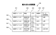
FIG. 6 is an example of the combination candidate table 128 in this embodiment. The combination candidate table 128 is an output of the combination
本実施形態の組み合わせ候補表128は、データソース、抽出処理、および、エンドポイントが一連となって組み合わされたセンシング手段たる、処理チェーンの識別子を格納する「処理チェーンID」欄501と、当該処理チェーンから出力されるデータの精度情報を格納する「精度」欄502と、当該処理チェーンから出力されるデータの料金情報を格納する「コスト」欄503と、当該処理チェーンの稼働率の情報を格納する「稼働率」欄504、および、当該処理チェーンのデータ出力間隔の情報を格納する「データ取得間隔」欄505から構成される。
The combination candidate table 128 of the present embodiment includes a "processing chain ID"
図6の組み合わせ候補表128において、例えば行505の処理チェーンは、処理チェーンIDが「処理チェーンID#1」(図7Aの処理チェーン表129)で識別される処理チェーンであり、その出力データの精度は「誤差半径5m以下」で、コストは「0.07円/分」、また、稼働率は「90%」となっている。
In the combination candidate table 128 of FIG. 6, for example, the processing chain of
なお、上述の精度「誤差半径5m以下」は、図7Aの処理チェーン表129に含まれるセンサ「Dev−#1」および抽出処理「抽出処理−#A」、「抽出処理−#B」、「抽出処理−#C」、のうち、最も精度の低い値である「誤差半径5m以下」を管理サーバ100が特定した値である。また、コスト「0.07円/分」は、同様に管理サーバ100が、センサ「Dev−#1」のコストと、抽出処理「抽出処理−#A」、「抽出処理−#B」、「抽出処理−#C」それぞれの入力に用いる「Type−#2」、「Type−#3」、「Type−#7」、の各コストとを、物理センサ属性表126のコスト欄308にて特定し、これらを合算した値である。また、稼働率「90%」は、管理サーバ100が、センサ「Dev−#1」の稼働率、抽出処理「抽出処理−#A」、「抽出処理−#B」、「抽出処理−#C」それぞれの入力に用いる「Type−#2」、「Type−#3」、「Type−#7」、の各稼働率とを、物理センサ属性表126の稼働率欄309にて特定し、これらを乗算した値である。
なお、上述の各種メタデータは、他の情報処理システムから取得したものであってもよい。
The above-mentioned accuracy "error radius of 5 m or less" is the sensor "Dev- # 1" included in the processing chain table 129 of FIG. 7A and the extraction processing "extraction processing- # A", "extraction processing- # B", "extraction processing- # B". Of the "extraction process- # C", the value "with an error radius of 5 m or less", which is the least accurate value, is specified by the
The above-mentioned various metadata may be acquired from another information processing system.
図7A〜図7Dは、本実施形態における処理チェーン表129の一例である。この処理チェーン表129は、上述の処理チェーンを構成する、一連の物理センサ20、抽出処理、およびエンドポイントと、それらの各間におけるデータの入出力関係を規定するテーブルである。
7A to 7D are examples of the processing chain table 129 in this embodiment. The processing chain table 129 is a table that defines a series of
こうした処理チェーン表129は、当該処理チェーンを構成する物理センサ20もしくは抽出処理の情報を格納する「入力」欄601と、当該入力欄601の物理センサ20のセンシングデータないし抽出処理の出力データの出力先となる抽出処理もしくはエンドポイント処理の情報を格納する「出力」欄604とから構成されている。
In the processing chain table 129, the
例えば、図7Aの処理チェーン表129において、行603は、物理センサ20「Dev−#1」を起点とする処理チェーンであり、この物理センサ20「Dev−#1」のセンシングデータの出力先が「抽出処理−#A」であることを示している。また同様に、行604は、「抽出処理−#A」から出力されたセンシングデータが、出力先の「抽出処理−#B」に入力されることを示している。また同様に、行605は、「抽出処理−#B」から出力されたセンシングデータが、出力先の「抽出処理−#C」に入力されることを示している。また同様に、行606は、「抽出処理−#C」から出力されたセンシングデータが、出力先の「エンドポイント処理A」に入力されることを示している。
For example, in the processing chain table 129 of FIG. 7A,
このように、図7Aの処理チェーン表129は、全体として、「Dev−#1⇒抽出処理−#A⇒抽出処理−#B⇒抽出処理−#C⇒エンドポイント処理A」の一連の流れでデータが処理されていく処理チェーンを表している。
−−−フロー例1−−−
As described above, the processing chain table 129 of FIG. 7A has a series of flow of "Dev- # 1 ⇒ extraction process- # A ⇒ extraction process- # B ⇒ extraction process- # C ⇒ endpoint process A" as a whole. It represents a processing chain in which data is processed.
--- Flow example 1 ---
以下、本実施形態におけるセンサネットワーク管理方法の実際手順について図に基づき説明する。以下で説明するセンサネットワーク管理方法に対応する各種動作は、センサネットワーク管理システム1を主として構成する管理サーバ100がメモリ等に読み出して実行するプログラムによって実現される。そして、このプログラムは、以下に説明される各種の動作を行うためのコードから構成されている。
Hereinafter, the actual procedure of the sensor network management method in the present embodiment will be described with reference to the drawings. Various operations corresponding to the sensor network management method described below are realized by a program that is read and executed by the
図8は、本実施形態におけるセンサネットワーク管理方法のフロー例1を示す図であり、具体的には、管理サーバ100のマッチング処理部112におけるフローチャートの一例である。
FIG. 8 is a diagram showing a flow example 1 of the sensor network management method in the present embodiment, and specifically, is an example of a flowchart in the
この場合、管理サーバ100のマッチング処理部112は、センシングデータを必要とするアプリケーションと、上述のアプリケーションの要件を満たすセンシングデータを提供できるセンシング手段との組み合わせを選択する。また、マッチング処理部112は、入出力処理部121を通して、上述のアプリケーションのユーザからアプリケーションの要件が入力された場合に実行される。
In this case, the matching
ここで、マッチング処理部112は、入出処理部111を介してユーザ等により生成された、アプリ属性表125、物理センサ属性表126、および、抽出処理管理表127の3種類の表を記憶装置101から読み出し、これらを入力として組み合わせ抽出処理部1121を呼び出し、組み合わせ候補表128を作成する(701)。この組み合わせ抽出処理部1121におけるフロー(図9)については後述する。
Here, the matching
次に、管理サーバ100は、上述のステップ701で生成された組み合わせ候補表128を入力として、組み合わせ選択処理部1122を呼び出し、組み合わせ候補表128のうち1行を、組み合わせ候補たるセンシング手段として選択する(702)。このステップ702の詳細については図10に基づき後述する。
Next, the
続いて、管理サーバ100は、上述のステップ702において選択した組み合わせ候補の処理チェーンID(例:「処理チェーンID#3」)を、アプリ属性表125における該当アプリケーションのレコード中の処理チェーンID欄207に登録する(703)。
以上のフローによって、アプリケーションと、その要件を満たすセンシング手段との組合せが決定される。
−−−フロー例2−−−
Subsequently, the
The above flow determines the combination of the application and the sensing means that meets the requirements.
--- Flow example 2 ---
図9は、本実施形態におけるセンサネットワーク管理方法のフロー例2を示す図であり、具体的には、上述のフロー例1における組み合わせ抽出処理部1121における処理のフロー例である。
FIG. 9 is a diagram showing a flow example 2 of the sensor network management method in the present embodiment, and specifically, is a flow example of processing in the combination
このフローは、組み合わせ抽出処理部1121が、センシングデータを必要とするアプリケーションと、上述のアプリケーションの要件を満たすセンシングデータを提供できるセンシング手段との組み合わせをリストアップする処理に対応するものである。なお、組み合わせ抽出処理部1121においては、エンドポイント処理を抽出処理の一つとして扱う。
This flow corresponds to a process in which the combination
この場合、組み合わせ抽出処理部1121は、「所望データ種別」を設定する(801
)。本処理は再帰的に複数回呼び出される。本処理を最初に実行する際には、アプリ属性表125のデータ種別において指定されているデータ種別をエンドポイント処理への入力として扱い、上述のデータ種別を所望データ種別とする。2回目以降の呼び出しでは、指定された抽出処理への入力を所望データ種別とする。
In this case, the combination
). This process is recursively called multiple times. When this process is first executed, the data type specified in the data type of the application attribute table 125 is treated as an input to the endpoint process, and the above data type is set as the desired data type. In the second and subsequent calls, the input to the specified extraction process is set as the desired data type.
例えば、当該ステップ801における組み合わせ抽出処理部1121は、アプリ属性表125における行210のデータ種別欄202を参照して所望データ種別を「Type−#1」とする。
For example, the combination
続いて、組み合わせ抽出処理部1121は、物理センサ属性表126のデータ種別列を参照して、所望データ種別を出力する物理センサをリストアップする(802)。
Subsequently, the combination
この処理に際し、一つ以上の物理センサ20が見つかった場合(802:YES)、組み合わせ抽出処理部1121は、当該物理センサ20を当入力の候補リストに登録する(803)。他方、上述の処理に際し、物理センサ20が見つからなかった場合(802:NO)、組み合わせ抽出処理部112は、ステップ803をスキップする。
If one or more
上述の例の場合、組み合わせ抽出処理部1121は、このステップ802において、物理センサ属性表126を参照すると、出力のデータ種別が「Type−#1」と一致する物理センサ20は存在しないため、ステップ803をスキップすることになる。
In the case of the above example, when the combination
続いて、組み合わせ抽出処理部1121は、抽出処理管理表127を参照し、所望データ種別のデータを出力する抽出処理を表す各行に対して、以下のステップ808までの処理を実行する(804)。
Subsequently, the combination
上述の例の場合、抽出処理管理表127に含まれる処理の中で出力が「Type−#1」と一致するのは、行413、行415、行416、行418の4つの処理のみであるため、組み合わせ抽出処理部1121は、この4行の各行に対してステップ808までの処理を繰り返し実行することになる。
In the case of the above example, among the processes included in the extraction process management table 127, the output matches "Type- # 1" only in the four processes of
このうちステップ805において、組み合わせ抽出処理部1121は、検索済みリストを参照し、ステップ804で指定された抽出処理に対して、既に検索を終えている場合はステップ808に進む。上述の例の場合、検索済みリストは空であるので、ステップ806に進むことになる。また、行413、行415、行416、行418の4つの処理のそれぞれについて、ステップ806において再帰的に組み合わせ抽出処理部1121が呼び出されることになる。
Of these, in
他方、ステップ804で指定された抽出処理に対して、既に検索を終えていない場合、組み合わせ抽出処理部1121は、ステップ806において、当該抽出処理を検索済みリ
ストに追加する。さらに、当該抽出処理に対して再帰的に本組み合わせ抽出処理部1121を呼び出す。上述の処理が終了した場合、組み合わせ抽出処理部1121は、検索済みリストから当該抽出処理を削除する。
また、ステップ807において、組み合わせ抽出処理部1121は、呼び出し結果を当入力の候補リストに追加する。
On the other hand, when the search has not been completed for the extraction process specified in
Further, in
また、上述のルーチン804〜808の終了後、ステップ809において、組み合わせ抽出処理部1121は、すべての入力に候補があるかどうかを判定する。この判定の結果、一つでも入力に候補がないものが存在した場合(809:NO)、組み合わせ抽出処理部1121は、ステップ810において、候補なしを返す。
Further, after the completion of the
他方、上述の判定の結果、すべての入力に対して候補があった場合(809:YES)、組み合わせ抽出処理部1121は、ステップ811において、各入力の候補リストの組み合わせに対する処理チェーン表129を作成し、結果リストに登録する。
On the other hand, if there are candidates for all the inputs as a result of the above determination (809: YES), the combination
次に、ステップ812において、組み合わせ抽出処理部1121は、本抽出処理がエンドポイント処理に対するものであるかどうか判定する。この判定の結果、本抽出処理がエンドポイント処理に対するものである場合(812:YES)、組み合わせ抽出処理部1121は、ステップ813において、結果リストの内容を組み合わせ候補表128として記録する。また、組み合わせ抽出処理部1121は、組み合わせ候補表128の精度、コストなどの欄の値を各エントリの処理チェーン表129から求めて登録する。
Next, in
続いて、組み合わせ抽出処理部1121は、ステップ813において、結果リストの各行に対して処理チェーンIDを振り、それぞれの行に対して、物理センサ属性表126および抽出処理管理表127を参照しながら、精度、コスト、稼働率を求めて登録する。
Subsequently, in
なお、精度欄には、処理チェーン表129に含まれるセンサおよび抽出処理について、物理センサ属性表126の精度欄307および抽出処理管理表127の精度欄409を参照しながら、最も精度の低い値を登録する。
また、コスト欄には、処理チェーン表129に含まれるセンサについて、物理センサ属性表126のコスト欄308を参照しながら、料金の和を登録する。
また、稼働率欄には、処理チェーン表129に含まれるセンサについて、物理センサ属性表126の稼働率欄309を参照しながら、稼働率の積を登録する。
In the accuracy column, for the sensors and extraction processing included in the processing chain table 129, the lowest accuracy value is entered with reference to the
Further, in the cost column, for the sensors included in the processing chain table 129, the sum of the charges is registered with reference to the
Further, in the operating rate column, the product of the operating rates is registered for the sensors included in the processing chain table 129 with reference to the
一方、上述の判定の結果、本抽出処理がエンドポイント処理に対するものでない場合(812:NO)、組み合わせ抽出処理部1121は、ステップ814において、結果リストを返して当該フローを終了する。
On the other hand, as a result of the above determination, when the present extraction process is not for the endpoint process (812: NO), the combination
ここで、上述のフローに関して更なる具体例を示す。ここでは、上述のステップ804での処理対象として、抽出処理管理表127の行413の「抽出処理−#C」に対して呼び出された組み合わせ抽出処理部1121の動作について説明する。便宜上、本組み合わせ抽出処理を抽出処理413とする。
Here, a further specific example of the above-mentioned flow will be shown. Here, the operation of the combination
この場合、組み合わせ抽出処理部1121は、ステップ801において、所望データ種別を「Type−#7」とする。また、組み合わせ抽出処理部1121は、ステップ802において、「Type−#7」のデータを出力するセンサは存在しないと判定する。
In this case, the combination
また、組み合わせ抽出処理部1121は、ステップ804において、再び抽出処理管理表127を参照し、「Type−#7」のデータを出力する抽出処理は行412のみであることを特定する。
Further, in
続いて、組み合わせ抽出処理部1121は、ステップ805において、検索済みリストには行413のみが記載されており、行412は含まれていないと特定する。
Subsequently, in
また、管理サーバ100は、ステップ806において、上述の行412を対象として組み合わせ抽出処理部1121を再度呼び出す。便宜上、ここで呼び出される組み合わせ抽出処理部を抽出処理412とする。抽出処理412の中では、同様に行411を対象として再度組み合わせ抽出処理部1121を呼び出す。便宜上、ここで呼び出される組み合わせ抽出処理部を抽出処理411とする。この抽出処理411においては、ステップ801において、所望データ種別を「Type−#2」とする。
Further, in
ステップ802において、「Type−#2」のデータを出力するセンサは行311が存在することがわかる。そこでステップ803において、組み合わせ抽出処理部1121は、行411の入力候補リストに行311を登録する。
In
また、組み合わせ抽出処理部1121は、ステップ804において、再び抽出処理管理表127を参照し、「Type−#2」のデータを出力する処理が存在しないことがわかるため、ステップ809に進む。
Further, in
また、組み合わせ抽出処理部1121は、ステップ809において、行411に対する入力の候補は、ステップ803において入力候補リストに行311が登録されていることがわかるため、ステップ811に進む。
Further, the combination
また、組み合わせ抽出処理部1121は、ステップ811においては、行411に対する入力データ種数は1であるため、候補リストの組み合わせに対する中身が空の処理チェーン表129を一つ作成する。さらに、組み合わせ抽出処理部1121は、データ種別「Type−#2」のデータを出力する「センサDev−#1」を入力欄601に、データ種別「Type−#2」のデータを入力されるとデータ種別「Type−#3」のデータを出力する「抽出処理−#A」を出力欄602に保持する行603が生成される。
また、組み合わせ抽出処理部1121は、処理チェーン表129に対して、行603を追加し、結果リストに登録する。
Further, since the number of input data types for the
Further, the combination
また、組み合わせ抽出処理部1121は、ステップ812において、本抽出処理への入力は行411でありエンドポイントではないため、ステップ814に進む。
Further, the combination
また、組み合わせ抽出処理部1121は、ステップ814においては、行605が登録された結果リストを返して抽出処理411を終了し、ここで抽出処理412のステップ806に戻る。続けて抽出処理412を検索済みリストから削除する。
Further, in
また、組み合わせ抽出処理部1121は、ステップ807において、ステップ806で得られた抽出処理411の結果である行603のみを保持する処理チェーン表129を、処理412に対する入力候補リストに追加する。
Further, in
また、組み合わせ抽出処理部1121は、ステップ808において、抽出処理412におけるステップ804から始まるループが終了する。ステップ809においては、行412に対する入力候補リストには抽出処理411の結果のみが格納されている。
Further, in
続いて、組み合わせ抽出処理部1121は、ステップ811において、データ種別「Type−#3」のデータを出力する「抽出処理−#A」を入力欄601に、データ種別「Type−#3」のデータを入力されるとデータ種別「Type−#7」のデータを出力する「抽出処理−#B」を出力欄602に保持する行604が生成されるので、生成された行607を結果リストに追加する。以降、組み合わせ抽出処理部1121は、抽出処理411と同様に、行604が追加された結果リストを返し、抽出処理413のステップ806に戻る。抽出処理413のステップ806以降も、抽出処理412、411と同様に処理され、データ種別「Type−#7」のデータを出力する「抽出処理−#B」を入力欄601に、データ種別「Type−#3」のデータを入力されるとデータ種別「Type−#7」のデータを出力する「抽出処理−#C」を出力欄602に保持する行605が生成されるので、行605が追加された結果リストを返し、ステップ806に戻る。ここまでの処理で、行606を除いた処理チェーン表129が生成されている。
Subsequently, in
ステップ806において、組み合わせ抽出処理部1121は、抽出処理413と同様に
して、行415を対象とした組み合わせ抽出処理部1121(抽出処理415)、行416を対象とした組み合わせ抽出処理部1121(抽出処理416)、行418を対象とした組み合わせ抽出処理部1121(抽出処理418)を実行する。
In
抽出処理415の結果として行615を除いた処理チェーン表129(図7B)、抽出処理416の結果として行622を除いた処理チェーン表129(図7C)、抽出処理418の結果として行626を除いた処理チェーン表129(図7D)が生成される。
Processing chain table 129 (FIG. 7B) excluding
各抽出処理のステップ807においてそれぞれの結果が入力の候補リストに登録される。ステップ809において、エンドポイント処理への入力候補リストは、行606を除いた処理チェーン表129、行615を除いた処理チェーン表129、行622を除いた処理チェーン表129、行626を除いた処理チェーン表129の4つの表となる。
In
ステップ811において、エンドポイント処理への入力は「Type−#1」のデータ一種類だけであるため、入力の組み合わせは入力候補リストの要素4つだけである。組み合わせ抽出処理部1121は、当該入力候補リスト内の組み合わせに対して、エンドポイントへの入力に関する情報を加える。
In
組み合わせ抽出処理部1121は、行609を除いた処理チェーン表129に対して、データ種別「Type−#1」のデータを出力する「抽出処理−#C」を入力欄601に、データ種別「Type−#1」のデータを入力にもつ「エンドポイント処理A」を出力欄602に保持する行606を追加し、処理チェーン表129を完成させる。
The combination
組み合わせ抽出処理部1121は、同様の処理を、行615を除いた処理チェーン表129、行622を除いた処理チェーン表129、行626を除いた処理チェーン表129に対しても行い、それぞれの結果として、図7A〜図7Cにおける各処理チェーン表129が完成する。
The combination
また、ステップ811の結果として、結果リストには、図7A〜図7Dにおける各処理チェーン表129の4つが登録される。組み合わせ抽出処理部1121は、ステップ812において、上述の各抽出処理はエンドポイントを出力とした組み合わせ抽出処理であるため、ステップ813に進む。
Further, as a result of
また、組み合わせ抽出処理部1121は、ステップ813において、結果リストの各行に対して処理チェーンIDを振り、それぞれの行に対して、物理センサ属性表126および抽出処理管理表127を参照しながら、精度、コスト、稼働率を求めて登録する。
Further, in
組み合わせ候補表128の行505は次のように生成される。組み合わせ抽出処理部1121は、処理チェーン表129(図7A)に対して処理チェーンIDとして「処理チェーンID#1」を振る。また組み合わせ抽出処理部1121は、精度欄に、処理チェーン表129に含まれるセンサおよび抽出処理のうち、最も精度の低い値である「誤差半径5m以下」を登録する。また組み合わせ抽出処理部1121は、コスト欄に、物理センサ属性表126のコスト欄を参照しながら、行314および行315のコスト欄308に記載された料金の和である「0.07円/分」を登録する。また組み合わせ抽出処理部1121は、稼働率欄に、処理チェーン表129に含まれるセンサの稼働率の積である「90%」を登録する。以上により、上述の抽出処理の結果として、組み合わせ候補表128が生成される。
Row 505 of the combination candidate table 128 is generated as follows. The combination
ここで選択ポリシー表130の例を図10に示す。この選択ポリシー表130は、組み合わせ選択処理部1122において、複数の組み合わせ候補の中から優先する候補を選択
するために利用される。
Here, an example of the selection policy table 130 is shown in FIG. This selection policy table 130 is used in the combination
本実施形態における選択ポリシー表130は、複数の指標間(テーブルの各行)での優先関係の値を格納する「優先度」欄901と、候補を選択するための指標を格納する「指標」欄902と、当該指標がどのようになると優先度が高いのかを示す情報を格納する「方向性」欄903と、から構成されている。
The selection policy table 130 in the present embodiment has a "priority"
なお、上述の指標欄902は、例えばセンシング手段を提供するためのコスト、センシング手段が提供するセンシングデータの精度、センシング手段を提供するためにデータ提供サーバ200データ提供サーバ200上に新たに構築する必要がある抽出処理数の数、データ提供サーバ200で必要となるCPU等の資源量、システムの運用管理者のオペレーションコストなどの数値を表している。
The
例えば、選択ポリシー表130の行906は優先度として「2」を保持している。そのため、優先度「1」の指標によって出力する候補が決定されなかった場合にのみ参照される。また、行906は指標として「抽出処理数」を、方向性として「最小化」を保持しているため、センシング手段をデータ提供サーバ200上に新たに構築する必要がある抽出処理数が小さくなる候補をより優先度が高い候補として取り扱う。
−−−フロー例3−−−
For example,
--- Flow example 3 ---
図11は、本実施形態におけるセンサネットワーク管理方法のフロー例3を示す図であり、具体的には組み合わせ選択処理部1122におけるフローチャートの一例である。
FIG. 11 is a diagram showing a flow example 3 of the sensor network management method in the present embodiment, and specifically, is an example of a flowchart in the combination
この場合、組み合わせ選択処理部1122による処理は、上述の組み合わせ抽出処理部1121によって生成された組み合わせ候補表128から、センシング手段候補を選び出す処理となる。組み合わせ選択処理部1122は、マッチング処理部112によって、組み合わせ抽出処理部1121に続いて呼び出される。
In this case, the process by the combination
このフローにおける組み合わせ選択処理部1122は、まず、ステップ1001において、組み合わせ候補表128に含まれている各行に対して、以下のステップ1004までの各処理を繰り返す。
First, in
このうちステップ1002においては、組み合わせ選択処理部1122は、ステップ1001で指定された行が表す組み合わせ候補が、アプリ属性表125のデータ取得間隔203、精度204、コスト205、稼働率206で指定されているアプリケーションの要件を満たすかどうか判定する。
Of these, in
上述の判定の結果、当該組み合わせ候補がアプリケーションの要件を満たす場合(1002:YES)、組み合わせ選択処理部1122は、ステップ1003において、当該組み合わせ候補を最終候補リストに追加する。
As a result of the above determination, when the combination candidate satisfies the requirements of the application (1002: YES), the combination
他方、当該組み合わせ候補がアプリケーションの要件を満たさない場合(1002:NO)、組み合わせ選択処理部1122は、ステップ1003をスキップする。
続いて、組み合わせ選択処理部1122は、ステップ1004において、ステップ1001から始まる繰り返し処理を終了する。
On the other hand, if the combination candidate does not meet the requirements of the application (1002: NO), the combination
Subsequently, the combination
その後、ステップ1005において、組み合わせ選択処理部1122は、最終候補リストが空かどうか判定する。この判定の結果、最終候補リストが空である場合(1005:YES)、組み合わせ選択処理部1122は、ステップ1006において、アプリケーションの要件を満たす候補が存在しない旨をユーザに通知し本処理を終了する。
Then, in
他方、ステップ1005における判定の結果、最終候補リストが空でない場合(1005:NO)、組み合わせ選択処理部1122は、テップ1007において選択ポリシー表130の優先度を参照して、望ましい候補が表の上部に出現するよう、組み合わせ候補表128の各行のソートを行う。
最後に、組み合わせ選択処理部1122は、ステップ1008において、表の一番上にある候補を出力する。
On the other hand, if the final candidate list is not empty as a result of the determination in step 1005 (1005: NO), the combination
Finally, the combination
上述のフローに伴う、より具体的な例を説明する。この場合、組み合わせ選択処理部1122は、ステップ1001において、組み合わせ候補表128の各行に対してステップ1004までの処理を実行する。また、組み合わせ選択処理部1122は、ステップ1002により、各行の項目がアプリケーションの要件を満たすかどうかを判定する。なお、以下では説明を簡易にするために組み合わせ候補票128のすべての項目が条件を満たす場合を例にあげて説明をする。
A more specific example accompanying the above flow will be described. In this case, the combination
図6で例示した組み合わせ候補表128の行505、506、507は、すべての項目が条件を満たすため、組み合わせ選択処理部1122は、ステップ1003において最終候補リストに追加する。また、行508はコスト欄503に「0.5円/分」が登録されており、アプリ属性表125のコスト欄204で指定されたコスト「0.1円/分以下」を満たさないため、組み合わせ選択処理部1122は、ステップ1003をスキップしてステップ1004に進む。
続いて、組み合わせ選択処理部1122は、ステップ1004において、ステップ1002から始まった繰り返し処理を終了する。
Since all the items of
Subsequently, in
また、組み合わせ選択処理部1122は、ステップ1005において、最終候補リストが空ではないためステップ1007に進む。また、ステップ1007で、組み合わせ選択処理部1122は、選択ポリシー表130を参照して各行のソートを行う。
Further, the combination
選択ポリシー表130の行905より、優先度が最も高い指標はコストかつ方向性は最小化であるため、組み合わせ選択処理部1122は、最終候補表に登録されている行505、706、707の中では、コストが「0.02円/分」である行507が最終候補表の一番上に来るようにソートされる。
Since the index with the highest priority is cost and direction is minimized from the
また、組み合わせ選択処理部1122は、ステップ1008にて、最終候補表の一番上にある行507を候補として出力する。以上によって、行507が選択処理の結果となる。
−−−フロー例4−−−
Further, in
--- Flow example 4 ---
図12は、本実施形態におけるセンサネットワーク管理方法のフロー例4を示す図であり、具体的には、基盤制御処理部113におけるフローチャートの一例である。
FIG. 12 is a diagram showing a flow example 4 of the sensor network management method in the present embodiment, and specifically, is an example of a flowchart in the board
この場合、基盤制御処理部113における処理は、マッチング処理部112によって特定されるセンシング手段をデータ提供サーバ200上に構築接続し、このセンシング手段による出力データをアプリケーションが利用できるようにする処理である。こうした基盤制御処理部113は、マッチング処理部112に続いて管理サーバ100に呼び出される。
In this case, the processing in the infrastructure
この場合、基盤制御処理部113は、ステップ1101において、構築接続処理部1131を実行し、入力された組み合わせ候補表128から特定される抽出処理とエンドポイントの構築接続処理を行う。
In this case, the infrastructure
また、構築接続処理部1131は、ステップ1102においては、アプリケーションからデータにアクセスするためのエンドポイントをデータ提供サーバ200上に構築する。
また、構築接続処理部1131は、ステップ1103においては、エンドポイントのエンドポイントIDをアプリ属性表125の中で、現在注目しているアプリケーションを表す行のエンドポイントID欄208に設定し、処理を終了する。
上述のフローにおける構築接続処理部1131の動作例として、組み合わせ候補表128の行507が入力された場合について説明する。
Further, in
Further, in
As an operation example of the construction
この場合、ステップ1101において、管理サーバ100は、マッチング処理部112に続いて構築接続処理部1131を呼び出す。この構築接続処理部1131によるステップ1101での詳細な動作例は図13で説明する。
In this case, in
続いて、構築接続処理部1131は、ステップ1102において、ステップ1101においてデータ提供サーバ200上に構築接続されたセンシング手段に、アプリケーションからアクセスできるようにする。アプリケーションからweb経由でアクセスが行われる場合、センシング手段に一意なURLを設定し、当該URLにリクエストが来た場合にセンシングデータを返送する処理をデータ提供サーバ200上に構築する。
Subsequently, in
続いて、構築接続処理部1131は、ステップ1103において、上述のステップ1102において構築されたエンドポイントに一意な識別子を設定し、アプリ属性表125のエンドポイントID欄208に登録する。ステップ1102においてエンドポイントに対して一意なURLを設定した場合は、当該URLをエンドポイントIDとみなすことができる。以上により、アプリケーションから所望のセンシングデータにアクセスすることが可能となる。
−−−フロー例5−−−
図13は、本実施形態におけるセンサネットワーク管理方法のフロー例5を示す図であり、具体的には構築接続処理部1131のフローチャートの一例である。
Subsequently, in
--- Flow example 5 ---
FIG. 13 is a diagram showing a flow example 5 of the sensor network management method in the present embodiment, and specifically, is an example of a flowchart of the construction
構築接続処理部1131における処理は、マッチング処理部112によって特定されるセンシング手段をデータ提供サーバ200上に構築、接続するための処理である。構築接続処理部1131は、マッチング処理部112に続く基盤制御処理部113の最初の処理として管理サーバ100から呼び出される。
The process in the construction
この場合、構築接続処理部1131は、ステップ1201において、処理チェーン表129の入力欄と出力欄に現れる各抽出処理に対して、ステップ1204までの処理を繰り返し実行する。
In this case, in
このうちステップ1202において、構築接続処理部1131は、ステップ1201において指定された抽出処理がデータ提供サーバ200上に構築済みであるかどうかを判定する。この判定の結果、構築済みである場合(1202:YES)、構築接続処理部1131は、ステップ1203をスキップする。
Of these, in
他方、上述の判定の結果、構築済みでない場合(1202:NO)、構築接続処理部1131は、ステップ1203において、抽出処理管理表127にて、構築する抽出処理のプログラムの抽出処理プログラムIDを参照し、これをキーにソースコードリポジトリ140にて該当ソースコードを特定し、当該ソースコードをデータ提供サーバ200上にコンパイルするなど適宜な実装処理を行う。なお、ステップ1204は、ステップ1201から始まった繰り返し処理の終端を表す。
次に、ステップ1205において、構築接続処理部1131は、処理チェーン表129
の各行に対してステップ1207までの処理を繰り返し実行する。
On the other hand, if the result of the above determination is that the construction has not been completed (1202: NO), the construction
Next, in
The process up to step 1207 is repeatedly executed for each line of.
このうちステップ1206において、構築接続処理部1131は、入力欄に指定されたデータソースもしくは抽出処理の出力を、出力欄に指定されている抽出処理もしくはエンドポイント処理の入力に設定する。なお、ステップ1207は、ステップ1205から始まった繰り返し処理の終端を表す。
Of these, in
上述のフローにおける構築接続処理部1131の具体的な動作例を如何に説明する。ここでは、マッチング処理部の結果である組み合わせ候補として、組み合わせ候補表128の行507が入力された場合を説明する。
A specific operation example of the construction
この場合、構築接続処理部1131は、ステップ1201において、行507の処理チェーンID欄501に登録されている処理チェーンID「処理チェーン#3」から辿ることができる、図7Cの処理チェーン表129を参照し、当該処理チェーン中に現れる「抽出処理−#B」、「抽出処理−#F」、「抽出処理−#G」のそれぞれに対してステップ1202とステップ1203の処理を行う。
In this case, the construction
「抽出処理−#B」に関して実行される処理では、ステップ1202において、「抽出処理−#B」は未構築であるため、ステップ1203に進む。また、ステップ1203において、構築接続処理部1131は、管理サーバ100上のソースコードリポジトリ140に格納されている「抽出処理−#B」を実行可能なソースコードをデータ提供サーバ200上に実装し、対応する処理を構築する。
In the process executed for the "extraction process- # B", since the "extraction process- # B" has not been constructed in
上述のステップ1201〜ステップ1204の繰り返し処理の結果、「抽出処理−#B」に関して実行される処理と同様に、構築接続処理部1131は、「抽出処理−#G」と「抽出処理−#F」についても、それぞれの処理を実行可能な処理をデータ提供サーバ200上に構築する。
この場合、構築接続処理部1131は、ステップ1205において、処理チェーン表129(図7C)の各行に対してステップ1206の処理をそれぞれ行う。
As a result of the iterative processing of
In this case, the construction
構築接続処理部1131は、ステップ1206において、センサ「Dev−#2」の出力が「抽出処理−#B」の入力に、「抽出処理−#B」の出力が「抽出処理−#F」の入力に、センサ「Dev−#3」の出力が「抽出処理−#G」の入力に、「抽出処理−#G」の出力が「抽出処理−#F」の入力に、「抽出処理−#F」の出力が「エンドポイント処理A」の入力になるようにそれぞれ設定を行う。以上によって、行507で表されるセンシング手段をデータ提供サーバ上に構築接続できた。
−−−フロー例6−−−
In
--- Flow example 6 ---
図14は、本実施形態におけるセンサネットワーク管理方法のフロー例6を示す図であり、具体的には、管理サーバ100における再選択処理部115のフローチャートの一例である。
FIG. 14 is a diagram showing a flow example 6 of the sensor network management method in the present embodiment, and specifically, is an example of a flowchart of the
本実施形態における再選択処理部115の処理は、一度、マッチング処理部112を経て選択されたセンシング手段を、再度選択し直すための処理である。この再選択処理部115は、例えば物理センサ20の異常により、アプリケーションへのセンシングデータの提供が途切れた場合に、管理サーバ100から呼び出される。
この場合、再選択処理部115は、ステップ1301において、異常がある物理センサ20を利用しているアプリケーション30を特定する。
再選択処理部115は、ここで特定したアプリケーション30に対して、以下のステップ1307までの各処理を実行する。
The process of the
In this case, the
The
上述のステップ1301において、アプリケーション30が特定された場合、再選択処理部115は、ステップ1302において、当該アプリケーション30のアプリ属性表125の処理チェーンIDを退避させる。
次に、再選択処理部115は、ステップ1303において、異常がある物理センサ20を利用している組み合わせを除いた組み合わせ候補表128を作成する。
When the
Next, in
続いて、再選択処理部115は、ステップ1304において、上述のステップ1303で作成した組み合わせ候補表128を利用して、組み合わせ選択処理を実行し、センシング手段を再選択する。
Subsequently, in
また、再選択処理部115は、ステップ1305において、上述のステップ1304において選択されたセンシング手段を、データ提供サーバ200上に構築・接続し、当該アプリケーション30が利用していたエンドポイントを通して、新たなセンシング手段によってデータが提供されるようにする。
Further, in
続いて、再選択処理部115は、ステップ1306において、上述のステップ1302において退避した処理チェーンIDを基にして、新たなセンシング手段に切り替えたことによって不要となった抽出処理をデータ提供サーバ200上から削除する。ステップ1307は、ステップ1301から始まった繰り返し処理の終端を表す。
Subsequently, in
上述のフローにおける再選択処理部115の動作例として、物理センサ「Dev−#3」からの通信が途絶えたことを、監視サーバ400が検知し、この旨を管理サーバ100に通知した状況での処理例を説明する。
As an operation example of the
この場合、再選択処理部115は、ステップ1301において、アプリ属性表125の処理チェーンID欄207に登録されている情報から処理チェーンを辿り、異常がある物理センサ20が利用されているアプリケーション30を特定する。
In this case, in
アプリ属性表125の行210が表すアプリケーションの処理チェーンID欄207に、「処理チェーン#1」が登録されているとすれば(図3の例では未登録状態)、再選択処理部115は、当該処理チェーンIDに対応する処理チェーン表129を図7Cの処理チェーン表と特定する。
If "
図7Cの処理チェーン表129に含まれるセンサは「Dev−#2」と「Dev−#3」の二つであり、行210が表すアプリケーション30は異常が起きた「Dev−#3」を利用していることがわかる。
Processing chain of FIG. 7C There are two sensors included in Table 129, “Dev- # 2” and “Dev- # 3”, and the
再選択処理部115は、ステップ1302において、アプリ属性表125にある処理チェーンIDを一時的に退避しておく。また、再選択処理部115は、ステップ1303において、物理センサ「Dev−#3」を表す行313を除いた表を入力として組み合わせ抽出処理部1121を実行する。
再選択処理部115は、この結果として、組み合わせ候補表128から行507を除いた表を出力する。
In
As a result of this, the
続いて、再選択処理部115は、ステップ1304において、組み合わせ候補表128から行507を除いた表を入力として、組み合わせ選択処理を実行する。当該組み合わせ選択処理のステップ1005の時点で、最終候補リストには組み合わせ候補表128の行506と行507が登録されている。当該組み合わせ選択処理のステップ1007においては、選択ポリシー表130を参照し、優先度を参照しながら組み合わせ候補表128の
ソートを行う。行506と行507は、再優先されるキーであるコストが共に「0.05円/分」である。しかし、2番目に優先されるキーである抽出処理数の観点では、既に「抽出処理−#B」がデータ提供サーバ200上に構築されていることから、新たに構築しなければならない抽出処理の数が行506では「抽出処理−#A」と「抽出処理−#C」の2つ、行507では「抽出処理−#A」と「抽出処理−#D」と「抽出処理−#E」の3つであることから行506が一番上に来るようにソートされる。
したがって、ステップ1304において出力される組み合わせ候補は、組み合わせ候補表128の行506である。
Subsequently, in
Therefore, the combination candidate output in
再選択処理部115は、ステップ1305において、組み合わせ候補表128の行506で指定される処理チェーンンをデータ提供サーバ200上に構築し、アプリケーションから処理チェーンの出力データにアクセスできる状態を維持する。
In
再選択処理部115は、ステップ1306において、アプリ属性表125における行210のエンドポイントID欄208を参照して、アプリケーション30にデータを提供しているエンドポイント処理136を特定する。再選択処理部115は、エンドポイント処理136への入力を、ステップ1305において構築した処理チェーンの末端である「抽出処理−#C」の出力に設定することで、エンドポイントを繋ぎかえる。
In
さらに、再選択処理部115は、行210の処理チェーンID欄207を「処理チェーンID#1」に更新する。ステップ1307は、ステップ1301から始まる繰り返し処理の終端を表す。
Further, the
再選択処理部115は、ステップ1308において、ステップ1308において退避した処理チェーンIDを元に、利用されなくなった抽出処理を、データ提供サーバ200上から消去する。以上によって、再選択処理部115における処理結果として、「処理チェーン#1」が表す手段をもってアプリケーション30にデータが提供されるようになった。
−−−フロー例7−−−
In
--- Flow example 7 ---
図15は、本実施形態におけるセンサネットワーク管理方法のフロー例7を示す図であり、具体的には、アンデプロイ処理部116のフローチャートの一例である。
FIG. 15 is a diagram showing a flow example 7 of the sensor network management method in the present embodiment, and specifically, is an example of a flowchart of the
本実施形態におけるアンデプロイ処理部116の処理は、アプリケーション30から利用されなくなった抽出処理をデータ提供サーバ200上から消すための処理であり、当該アプリケーション30が終了されたときや、センシング手段の切り替えが発生するときに呼び出される。ここでの動作例として、アプリケーション30(図1における、"アプリ
App−#1")の利用をユーザが終了した場合を説明する。
The process of the
まず、アンデプロイ処理部116は、ステップ1401において、アプリ属性表125においてアプリケーション30を表す行210の処理チェーンID欄207から処理チェーン表602を辿り、アプリケーション30から「抽出処理−#A」、「抽出処理−#B」、「抽出処理−#C」が利用されていることを特定し、それぞれの抽出処理をデータ提供サーバ200上から削除する。
First, in step 1401, the
次に、アンデプロイ処理部116は、ステップ1402において、アプリ属性表125の行210のエンドポイントID欄208から、エンドポイント処理136を特定し、データ提供サーバ200上から削除する。
Next, in step 1402, the
以上により、アンデプロイ処理部116の結果として、上述の「アプリApp−#1」
の終了によって不要となった抽出処理がデータ提供サーバ200上から削除された。
−−−インタフェースの例−−−
As a result of the
The extraction process that became unnecessary due to the end of is deleted from the
--- Example of interface ---
本実施形態におけるセンサネットワーク管理システム1は、所定のユーザや管理者に対してユーザインタフェースを提供することができる。図16は、アプリケーション30が必要とするデータの要件をユーザに入力させるべく、管理サーバ100が提供する画面1500の例である。
The sensor
この画面1500において、ユーザは、所定の端末を操作してファイル選択ボックス1501においてアプリケーション30の要件を記述したファイルを指定する。その後、当該ユーザは、アップロードボタン1502を押下する。上述の端末はこのアップロードボタン1502の押下を受け、指定したファイルを管理サーバ100に送信する。
On this
続いて、図17に、アプリケーション30の要件を満たすセンシング手段を、アプリケーション30のユーザに選択させるために管理サーバ100が提供する画面1601の例を示す。
Subsequently, FIG. 17 shows an example of the
図11のフローでは、組み合わせ選択処理部1122において、選択ポリシー表130に記載された優先度にしたがって決定された組み合わせを自動的に選択する例を説明した。しかしながら、組み合わせ候補表128の中から、ユーザが手動にてセンシング手段の候補を選択するとしてもよい。その場合、組み合わせ選択用の画面1601を、アプリケーション30のユーザに操作させ、所望のセンシング手段を選択させることとなる。
In the flow of FIG. 11, an example has been described in which the combination
図17においては、図8におけるステップ702の組み合わせ抽出処理部1121の処理が終了した後、ユーザの所定端末に表示する、組み合わせ候補確認画面1601の例を示している。当該ユーザは、端末を操作し、画面1601に表示される組み合わせ候補表128の中から、アプリケーション30で利用したいセンシング手段を探し出す。なお、組み合わせ候補表128は一行が一組み合わせを表している。
FIG. 17 shows an example of the combination
図17の画面1601においては、組み合わせ候補1608における処理チェーンID列1602の欄には、「処理チェーン#1」という情報がハイパーリンク形式で表示されている。このリンク先を表示することで、ユーザは処理チェーン表129を表示することができる。各組み合わせの内容を確認した後、ユーザは選択した候補行の選択列1606に表示されている構築ボタンを押下する。端末は、この押下を受けて、ユーザ所望の組み合わせのセンシング手段を管理サーバ100に通知する。管理サーバ100は、当該センシング手段をデータ提供サーバ200上に構築することとなる。
In the
また図18に、ある実装における、センサネットワーク管理システム1の運用者向け管理画面1701の例を示す。この運用者向け管理画面1701は、センシング手段の切り替えを運用者によって行うための画面であり、組み合わせ選択処理におけるステップ1007およびステップ1008で表される、候補を選択する処理を手動で行うことができるようにする画面である。
Further, FIG. 18 shows an example of the
この運用者向け管理画面1701は、あるアプリケーション30に対する組み合わせ候補表128に含まれている組み合わせの候補を表示するための組み合わせ候補表示部1704、1705と、組み合わせ候補詳細表示部1706、1707と、選択したセンシング手段への切り替えを実行するための切替ボタン1708とから構成される。
The
ここでの動作例として、物理センサ20の提供者から、センサネットワーク管理システム1の運用者に対して、デバイスID「Dev−#3」をもつ物理センサ20を緊急的に
停止させる旨の連絡が届き、センサネットワーク管理システム1の運用者が、「Dev−#3」をもつ物理センサ20を利用したセンシング手段を、「Dev−#3」をもつ物理センサ20を利用していない他のセンシング手段に切り替えるという場合を説明する。
As an operation example here, the provider of the
この場合、センサネットワーク管理システム1の運用者は、所定の端末を操作し、アプリ属性表125の処理チェーンIDから処理チェーンを辿り、「Dev−#3」をもつ物理センサ20を利用しているセンシング手段のエンドポイントを特定する。
In this case, the operator of the sensor
ここでは、物理センサ「Dev−#3」を利用したセンシング手段として、組み合わせ候補表128の行507にあたるセンシング手段を図にしたものが組み合わせ表示部1704に、当該センシング手段の詳細が詳細表示部1706表示されている。
Here, as the sensing means using the physical sensor "Dev- # 3", the
センサネットワーク管理システム1の運用者は、端末を操作して、運用者向け管理画面1701に表示されている他の組み合わせ候補を確認し、切り替え先のセンシング手段を選択する。「エンドポイントA」に対する別のセンシング手段候補として、組み合わせ候補表128の行505にあたるセンシング手段を図にしたものが組み合わせ表示部1705に、当該センシング手段の詳細が詳細表示部1707に表示されている。画面下部には続けて「エンドポイントA」に対する別のセンシング手段候補が表示されている。
The operator of the sensor
センサネットワーク管理システム1の運用者が、切替ボタン1708を押下すると、組み合わせ候補表128の行505が指定された状態で、再選択処理部115のステップ1305以降が実行される。
When the operator of the sensor
以上により、センシングデータと、それらのデータに対して抽出処理を適用して生成されるデータを、アプリケーション30の要件のマッチング対象とすることが可能となる。また、利用中のセンシング手段が利用できなくなった場合に、代替手段に切り替えることで、アプリケーション30へのデータ提供が継続可能となる。さらに、データ提供にかかるコストや、物理センサ20や抽出処理の管理コストを低減させるために、センシング手段を切り替えることが可能となる。
As described above, the sensing data and the data generated by applying the extraction process to the data can be matched with the requirements of the
なお、アプリケーション30から要求されるデータの検索対象は、センシングデータのみならず、インターネットなど適宜なネットワーク上で任意のユーザに公開されているデータやアプリケーション実行者にアクセスが許されている非公開データをはじめとした、ネットワーク上に存在していてアプリケーション30からアクセス可能な任意のデータ、あるいは、それらの組み合わせを対象としてもよい。
The data to be searched for by the
また、本実施形態では、抽出処理として、管理サーバ100のソースコードリポジトリ140にて管理されるソースコードを対象としているが、これは、実行可能な形態で登録されていてもよい。さらに、ネットワークで到達可能な別サーバ上で、SaaS(Software as a Service)などの形態で提供される処理を抽出処理としてもよい。
Further, in the present embodiment, the source code managed in the
以上、本発明を実施するための最良の形態などについて具体的に説明したが、本発明はこれに限定されるものではなく、その要旨を逸脱しない範囲で種々変更可能である。 Although the best mode for carrying out the present invention has been specifically described above, the present invention is not limited to this, and various modifications can be made without departing from the gist thereof.
こうした本実施形態によれば、物理センサから直接提供されるセンシングデータのみならず、それらセンシングデータに対して所定の処理を適用して生成されるデータを、アプリケーションの要件のマッチング対象とすることができる。また、アプリケーションによって利用中の物理センサが利用できなくなった場合に、代替の物理センサへの切り替えを可能とし、これによりアプリケーションへのデータ提供の継続性が維持される。さらに、
複数のアプリケーションそれぞれにデータ提供する際に必要となる、物理センサ数やセンサデータに適用する処理数を抑制可能であり、データ提供や管理用のコストを低減することができる。
すなわち、センサネットワークにおける物理センサのセンシングデータを、アプリケーションの要件に応じた形態で柔軟に提供可能となる。
According to the present embodiment, not only the sensing data directly provided from the physical sensor but also the data generated by applying a predetermined process to the sensing data can be matched with the requirements of the application. it can. In addition, when the physical sensor in use becomes unavailable due to the application, it is possible to switch to an alternative physical sensor, thereby maintaining the continuity of data provision to the application. further,
It is possible to suppress the number of physical sensors and the number of processes applied to the sensor data, which are required when providing data to each of a plurality of applications, and it is possible to reduce the cost for data provision and management.
That is, it is possible to flexibly provide the sensing data of the physical sensor in the sensor network in a form according to the requirements of the application.
本明細書の記載により、少なくとも次のことが明らかにされる。すなわち、本実施形態のセンサネットワーク管理方法において、前記情報処理システムが、前記マッチング処理により特定したセンシング手段に含まれる所定のデータ抽出手段を構築する処理を更に実行する、としてもよい。 The description herein reveals at least the following: That is, in the sensor network management method of the present embodiment, the information processing system may further execute a process of constructing a predetermined data extraction means included in the sensing means specified by the matching process.
これによれば、例えば、マッチング処理によって選択された処理チェーンをデータ提供サーバ上に構築し、該当アプリケーションから利用できる状態に実装可能となる。 According to this, for example, a processing chain selected by matching processing can be constructed on a data providing server and implemented in a state where it can be used by the corresponding application.
また、本実施形態のセンサネットワーク管理方法において、前記情報処理システムが、前記マッチング処理により特定したセンシング手段における所定のデータ抽出手段による処理結果に、前記所定アプリケーションからアクセス可能とするためのエンドポイントを構築する処理を更に実行する、としてもよい。 Further, in the sensor network management method of the present embodiment, the endpoint for enabling the information processing system to access the processing result by the predetermined data extraction means in the sensing means specified by the matching process from the predetermined application. The process of constructing may be further executed.
これによれば、センシング手段が最終的に出力するデータを、アプリケーションが利用出来るよう、当該データの取得先すなわちエンドポイント(例:出力データを要求するコマンドの送信先や、出力データの配置アドレスなど)を生成し、これをアプリケーションに利用させることが可能となる。 According to this, the data finally output by the sensing means can be used by the application, such as the acquisition destination of the data, that is, the endpoint (eg, the destination of the command requesting the output data, the location address of the output data, etc. ) Can be generated and used by the application.
また、本実施形態のセンサネットワーク管理方法において、前記情報処理システムが、前記マッチング処理により特定したセンシング手段における所定の物理センサと所定のデータ抽出手段と所定のエンドポイント処理を接続する処理を更に実行する、としてもよい。 Further, in the sensor network management method of the present embodiment, the information processing system further executes a process of connecting a predetermined physical sensor, a predetermined data extraction means, and a predetermined endpoint process in the sensing means specified by the matching process. You may do.
これによれば、例えば、マッチング処理によって選択された処理チェーンに含まれている抽出処理を、ソースコードリポジトリに保管されているソースコードを基にして、データ提供サーバ上で動く状態にし、また、それらの抽出処理を接続して、該当アプリケーションが要求しているデータを生成可能な状態にすることが可能である。 According to this, for example, the extraction process included in the process chain selected by the matching process can be made to run on the data providing server based on the source code stored in the source code repository. It is possible to connect these extraction processes so that the data requested by the relevant application can be generated.
また、本実施形態のセンサネットワーク管理方法において、前記情報処理システムが、少なくとも所定の不具合が発生するタイミングを含む所定のタイミングにおいて、前記アプリケーションのセンシング手段を、他のセンシング手段に切り換える処理を実行する、としてもよい。 Further, in the sensor network management method of the present embodiment, the information processing system executes a process of switching the sensing means of the application to another sensing means at a predetermined timing including at least a timing when a predetermined defect occurs. , May be.
これによれば、例えば物理センサに不具合が生じても、これに対応し、アプリケーションの要件を満たすセンシング手段を新たに特定してアプリケーションに提供出来る。 According to this, even if a defect occurs in a physical sensor, for example, it is possible to newly identify a sensing means that satisfies the requirements of the application and provide it to the application.
また、本実施形態のセンサネットワーク管理方法において、前記情報処理システムが、所定センシング手段に含まれるデータ抽出手段を利用しなくなるイベントが発生した場合、前記センシング手段に含まれる構築済みのデータ抽出手段をアンデプロイする処理を更に実行する、としてもよい。
これによれば、利用機会が無くなったデータ抽出手段をセンシング手段から削除し、リリースの利用効率を改善することが出来る。
Further, in the sensor network management method of the present embodiment, when an event occurs in which the information processing system does not use the data extraction means included in the predetermined sensing means, the constructed data extraction means included in the sensing means is used. The process of undeploying may be further executed.
According to this, it is possible to remove the data extraction means whose usage opportunity has disappeared from the sensing means and improve the utilization efficiency of the release.
また、本実施形態のセンサネットワーク管理方法において、前記情報処理システムが、
所定センシング手段に含まれるエンドポイント処理を利用しなくなるイベントが発生した場合、前記センシング手段に含まれる構築済みのエンドポイント処理を削除する処理を更に実行する、としてもよい。
これによれば、不要となったエンドポイント処理を削除し、システム全体を効率化出来る。
Further, in the sensor network management method of the present embodiment, the information processing system
When an event occurs in which the endpoint process included in the predetermined sensing means is no longer used, a process of deleting the constructed endpoint process included in the sensing means may be further executed.
According to this, it is possible to delete unnecessary endpoint processing and improve the efficiency of the entire system.
また、本実施形態のセンサネットワーク管理方法において、前記情報処理システムが、前記物理センサのメタデータ、所定のデータ抽出手段のメタデータ、前記物理センサのセンシングデータまたは当該センシングデータに基づく所定データ、および、前記物理センサのセンシングデータまたは当該センシングデータに基づく所定データを利用するアプリケーションのメタデータ、の少なくともいずれかとして、他の情報処理システムから取得する所定データも含めて保持する、としてもよい。 Further, in the sensor network management method of the present embodiment, the information processing system has the metadata of the physical sensor, the metadata of the predetermined data extraction means, the sensing data of the physical sensor or the predetermined data based on the sensing data, and , The sensing data of the physical sensor or the metadata of the application that uses the predetermined data based on the sensing data, may be retained including the predetermined data acquired from another information processing system.
これによれば、センサネットワークの範囲等を限定せず、物理センサのセンサデータを、アプリケーションの要件に応じた形態で、より柔軟かつ効率的に提供可能となる。 According to this, the sensor data of the physical sensor can be provided more flexibly and efficiently in a form according to the requirements of the application without limiting the range of the sensor network.
また、本実施形態のセンサネットワーク管理方法において、前記情報処理システムが、前記マッチング処理に際し、マッチング結果として得た複数のセンシング手段のうち、アプリケーションのメタデータが示す所定要件の全項目を満たすセンシング手段、もしくは、アプリケーションのメタデータが示す所定要件のうち一部項目を満たすセンシング手段を特定する、としてもよい。 Further, in the sensor network management method of the present embodiment, the information processing system satisfies all the items of the predetermined requirements indicated by the metadata of the application among the plurality of sensing means obtained as the matching result in the matching process. Alternatively, a sensing means that satisfies some of the predetermined requirements indicated by the metadata of the application may be specified.
これによれば、アプリケーションにとって最適なデータを取得出来るセンシング手段を特定し、提供する事が出来る。また、例えばアプリケーションの要件が多岐に亘るものであっても、必須のものは限定的であるといった状況に対して柔軟に対応し、必要以上に限定しない範囲でセンシング手段を特定、提供することが出来る。 According to this, it is possible to identify and provide a sensing means capable of acquiring the optimum data for the application. In addition, for example, even if the requirements of the application are diverse, it is possible to flexibly respond to the situation where the essential ones are limited, and to specify and provide the sensing means within the range not limited more than necessary. You can.
また、本実施形態のセンサネットワーク管理方法において、前記情報処理システムが、前記マッチング処理に際し、アプリケーションのメタデータが示す所定要件を満たすセンシング手段を特定出来なかった場合、当該アプリケーションに対し、要件を満たすセンシング手段が特定出来なかった旨を通知する処理を更に実行する、としてもよい。
これによれば、センサネットワークでそもそも適宜なデータが得られない状況を、アプリケーションが認識し、無用な対応を回避することが可能となる。
Further, in the sensor network management method of the present embodiment, when the information processing system cannot specify a sensing means that satisfies a predetermined requirement indicated by the metadata of the application in the matching process, the requirement is satisfied for the application. The process of notifying that the sensing means could not be specified may be further executed.
According to this, the application can recognize the situation where appropriate data cannot be obtained in the sensor network in the first place, and can avoid unnecessary measures.
また、本実施形態のセンサネットワーク管理方法において、前記情報処理システムが、前記マッチング処理に際し、マッチング結果として得た複数のセンシング手段に関して、所定ユーザによる選択を受け付ける処理を更に実行する、としてもよい。
これによれば、センサネットワーク管理システム側で適宜なセンシング手段を特定するのみならず、ユーザからの選択も受け付けることを可能とする。
Further, in the sensor network management method of the present embodiment, the information processing system may further execute a process of accepting selection by a predetermined user with respect to a plurality of sensing means obtained as matching results in the matching process.
According to this, it is possible not only to specify an appropriate sensing means on the sensor network management system side but also to accept selection from the user.
また、本実施形態のセンサネットワーク管理システムにおいて、前記演算装置は、前記アプリケーションが、前記センシング手段により提供されるデータの利用を中止する場合、または、所定センシング手段に含まれる物理センサが利用不可となった場合、前記アプリケーションに関して構築済みである前記センシング手段におけるデータ抽出手段の削除処理を更に実行するものである、としてもよい。 Further, in the sensor network management system of the present embodiment, when the application stops using the data provided by the sensing means, or when the physical sensor included in the predetermined sensing means cannot be used. In that case, the deletion process of the data extraction means in the sensing means already constructed for the application may be further executed.
また、本実施形態のセンサネットワーク管理システムにおいて、前記演算装置は、所定センシング手段に含まれるデータ抽出手段が利用不可となった場合、前記センシング手段に含まれる他の構築済みのデータ抽出手段をアンデプロイする処理を更に実行するものである、としてもよい。
これによれば、センシング手段を構成し、互いの出力を入力として連なっているデータ抽出手段らを、利用要否に応じて効率良く管理出来る。
Further, in the sensor network management system of the present embodiment, when the data extraction means included in the predetermined sensing means becomes unavailable, the arithmetic unit deploys another constructed data extraction means included in the sensing means. It may be that the process of deploying is further executed.
According to this, it is possible to efficiently manage the data extraction means that configure the sensing means and connect each other's outputs as inputs according to the necessity of use.
また、本実施形態のセンサネットワーク管理システムにおいて、前記演算装置は、前記マッチング処理により特定したセンシング手段に含まれる所定のデータ抽出手段を構築する処理を更に実行するものである、としてもよい。 Further, in the sensor network management system of the present embodiment, the arithmetic unit may further execute a process of constructing a predetermined data extraction means included in the sensing means specified by the matching process.
また、本実施形態のセンサネットワーク管理システムにおいて、前記演算装置は、前記マッチング処理により特定したセンシング手段における所定のデータ抽出手段による処理結果に、前記所定アプリケーションからアクセス可能とするためのエンドポイントを構築する処理を更に実行するものである、としてもよい。 Further, in the sensor network management system of the present embodiment, the arithmetic unit constructs an endpoint for making the processing result by the predetermined data extraction means in the sensing means specified by the matching process accessible from the predetermined application. It may be said that the processing to be performed is further executed.
また、本実施形態のセンサネットワーク管理システムにおいて、前記演算装置は、前記マッチング処理により特定したセンシング手段における所定の物理センサと所定のデータ抽出手段と所定のエンドポイント処理を接続する処理を更に実行するものである、としてもよい。 Further, in the sensor network management system of the present embodiment, the arithmetic unit further executes a process of connecting a predetermined physical sensor, a predetermined data extraction means, and a predetermined endpoint process in the sensing means specified by the matching process. It may be a thing.
1 センサネットワーク管理システム
5 センサネットワーク
10、11 ネットワーク
20 センサ
30 アプリケーション
100 管理サーバ
101 記憶装置
102 プログラム
103 メモリ
104 演算装置
105 通信装置
110 センサ情報取得処理部
111 入出力処理部
112 マッチング処理部
1121 組み合わせ抽出処理部
1122 組み合わせ選択処理部
113 基盤制御処理部
1131 構築接続処理部
1132 エンドポイント作成処理部
114 アラート受信処理部
115 再選択処理部
116 アンデプロイ処理部
125 アプリ属性表
126 物理センサ属性表
127 抽出処理管理表
128 組み合わせ候補表
129 処理チェーン表
130 選択ポリシー表
140 ソースコードリポジトリ
200 データ提供サーバ
300 IoTハブサーバ
310 出力処理部
400 監視サーバ
1 Sensor
Claims (15)
各前記データ抽出手段の出力データの精度と、各前記物理センサの稼働率及び出力データの精度とに基づき、前記アプリケーションが要求する前記可動率及びセンシングデータの精度を満たす、物理センサとデータ抽出手段との組み合わせであるセンシング手段を特定するマッチング処理を実行する、
ことを特徴とするセンサネットワーク管理方法。 Metadata including the operating rate of the physical sensor included in the sensor network and the accuracy of the output data, the metadata regarding the accuracy of the output data of the predetermined data extraction means, and the sensing data of the physical sensor or the predetermined data based on the sensing data. An information processing system equipped with a storage device that holds metadata including mobility and the accuracy of sensing data, which is the percentage of time that the physical sensor provides normal sensing data, which is required by the application to be used.
The physical sensor and the data extraction means that satisfy the accuracy of the mobility and the sensing data required by the application based on the accuracy of the output data of each of the data extraction means and the accuracy of the operating rate and the output data of each of the physical sensors. Performs a matching process that identifies the sensing means in combination with
A sensor network management method characterized by this.
前記マッチング処理により特定したセンシング手段に含まれる所定のデータ抽出手段を構築する処理を更に実行する、
ことを特徴とする請求項1に記載のセンサネットワーク管理方法。 The information processing system
Further executing the process of constructing the predetermined data extraction means included in the sensing means specified by the matching process.
The sensor network management method according to claim 1.
前記マッチング処理により特定したセンシング手段における所定のデータ抽出手段による処理結果に、前記所定アプリケーションからアクセス可能とするためのエンドポイントを構築する処理を更に実行する、
ことを特徴とする請求項2に記載のセンサネットワーク管理方法。 The information processing system
Further, a process of constructing an endpoint for making the processing result of the predetermined data extraction means in the sensing means specified by the matching process accessible from the predetermined application is executed.
The sensor network management method according to claim 2.
前記マッチング処理により特定したセンシング手段における所定の物理センサと所定のデータ抽出手段と所定のエンドポイント処理を接続する処理を更に実行する、
ことを特徴とする請求項3に記載のセンサネットワーク管理方法。 The information processing system
Further executing a process of connecting a predetermined physical sensor, a predetermined data extraction means, and a predetermined endpoint process in the sensing means specified by the matching process.
The sensor network management method according to claim 3, wherein the sensor network management method is characterized.
少なくとも所定の不具合が発生するタイミングを含む所定のタイミングにおいて、前記アプリケーションのセンシング手段を、他のセンシング手段に切り換える処理を実行する、
ことを特徴とする請求項4に記載のセンサネットワーク管理方法。 The information processing system
A process of switching the sensing means of the application to another sensing means is executed at a predetermined timing including at least a timing at which a predetermined defect occurs.
The sensor network management method according to claim 4.
所定センシング手段に含まれるデータ抽出手段を利用しなくなるイベントが発生した場合、前記センシング手段に含まれる構築済みのデータ抽出手段をアンデプロイする処理を更に実行する、
ことを特徴とする請求項4のセンサネットワーク管理方法。 The information processing system
When an event occurs in which the data extraction means included in the predetermined sensing means is no longer used, a process of undeploying the constructed data extraction means included in the sensing means is further executed.
The sensor network management method according to claim 4, wherein the sensor network is managed.
所定センシング手段に含まれるエンドポイント処理を利用しなくなるイベントが発生した場合、前記センシング手段に含まれる構築済みのエンドポイント処理を削除する処理を更に実行する、
ことを特徴とする請求項4のセンサネットワーク管理方法。 The information processing system
When an event occurs in which the endpoint processing included in the predetermined sensing means is no longer used, a process of further deleting the constructed endpoint process included in the sensing means is further executed.
The sensor network management method according to claim 4, wherein the sensor network is managed.
前記物理センサのメタデータ、所定のデータ抽出手段のメタデータ、前記物理センサのセンシングデータまたは当該センシングデータに基づく所定データ、および、前記物理センサのセンシングデータまたは当該センシングデータに基づく所定データを利用するアプリケーションのメタデータ、の少なくともいずれかとして、他の情報処理システムから取
得する所定データも含めて保持する、
ことを特徴とする請求項1のセンサネットワーク管理方法。 The information processing system
The metadata of the physical sensor, the metadata of the predetermined data extraction means, the sensing data of the physical sensor or the predetermined data based on the sensing data, and the sensing data of the physical sensor or the predetermined data based on the sensing data are used. Holds predetermined data acquired from other information processing systems as at least one of the application metadata.
The sensor network management method according to claim 1.
前記マッチング処理に際し、マッチング結果として得た複数のセンシング手段のうち、アプリケーションのメタデータが示す所定要件の全項目を満たすセンシング手段、もしくは、アプリケーションのメタデータが示す所定要件のうち一部項目を満たすセンシング手段を特定する、
ことを特徴とする請求項1のセンサネットワーク管理方法。 The information processing system
Of the plurality of sensing means obtained as the matching result in the matching process, the sensing means that satisfies all the predetermined requirements indicated by the application metadata, or some items among the predetermined requirements indicated by the application metadata are satisfied. Identify the sensing means,
The sensor network management method according to claim 1.
前記マッチング処理に際し、アプリケーションのメタデータが示す所定要件を満たすセンシング手段を特定出来なかった場合、当該アプリケーションに対し、要件を満たすセンシング手段が特定出来なかった旨を通知する処理を更に実行する、
ことを特徴とする請求項1のセンサネットワーク管理方法。 The information processing system
In the matching process, if the sensing means satisfying the predetermined requirement indicated by the metadata of the application cannot be specified, the process of notifying the application that the sensing means satisfying the requirement cannot be specified is further executed.
The sensor network management method according to claim 1.
前記マッチング処理に際し、マッチング結果として得た複数のセンシング手段に関して、所定ユーザによる選択を受け付ける処理を更に実行する、
ことを特徴とする請求項1のセンサネットワーク管理方法。 The information processing system
In the matching process, a process of accepting selection by a predetermined user is further executed for the plurality of sensing means obtained as the matching result.
The sensor network management method according to claim 1.
各前記データ抽出手段の出力データの精度と、各前記物理センサの稼働率及び出力データの精度とに基づき、前記アプリケーションが要求する前記可動率及びセンシングデータの精度を満たす、物理センサとデータ抽出手段との組み合わせであるセンシング手段を特定するマッチング処理を実行する演算装置と、
を備えるセンサネットワーク管理システム。 Metadata including the operating rate of the physical sensor included in the sensor network and the accuracy of the output data, the metadata regarding the accuracy of the output data of the predetermined data extraction means, and the sensing data of the physical sensor or the predetermined data based on the sensing data. A storage device that holds metadata that includes the mobility and the accuracy of the sensing data, which is the percentage of time that the physical sensor provides normal sensing data, as required by the application to be used.
The physical sensor and the data extraction means that satisfy the accuracy of the mobility and the sensing data required by the application based on the accuracy of the output data of each of the data extraction means and the accuracy of the operating rate and the output data of each of the physical sensors. An arithmetic device that executes matching processing to specify the sensing means, which is a combination of
Sensor network management system with.
前記マッチング処理により特定したセンシング手段に含まれる所定のデータ抽出手段を構築する処理を更に実行するものである、
ことを特徴とする請求項12に記載のセンサネットワーク管理システム。 The arithmetic unit
The process of constructing a predetermined data extraction means included in the sensing means specified by the matching process is further executed.
The sensor network management system according to claim 12.
前記マッチング処理により特定したセンシング手段における所定のデータ抽出手段による処理結果に、前記所定アプリケーションからアクセス可能とするためのエンドポイントを構築する処理を更に実行するものである、
ことを特徴とする請求項13に記載のセンサネットワーク管理システム。 The arithmetic unit
The process of constructing an endpoint for making the processing result of the predetermined data extraction means in the sensing means specified by the matching process accessible from the predetermined application is further executed.
The sensor network management system according to claim 13.
前記マッチング処理により特定したセンシング手段における所定の物理センサと所定のデータ抽出手段と所定のエンドポイント処理を接続する処理を更に実行するものである、
ことを特徴とする請求項14に記載のセンサネットワーク管理システム。 The arithmetic unit
Further, a process of connecting a predetermined physical sensor, a predetermined data extraction means, and a predetermined endpoint process in the sensing means specified by the matching process is executed.
The sensor network management system according to claim 14.
Priority Applications (1)
| Application Number | Priority Date | Filing Date | Title |
|---|---|---|---|
| JP2017018985A JP6872919B2 (en) | 2017-02-03 | 2017-02-03 | Sensor network management method and sensor network management system |
Applications Claiming Priority (1)
| Application Number | Priority Date | Filing Date | Title |
|---|---|---|---|
| JP2017018985A JP6872919B2 (en) | 2017-02-03 | 2017-02-03 | Sensor network management method and sensor network management system |
Publications (2)
| Publication Number | Publication Date |
|---|---|
| JP2018124935A JP2018124935A (en) | 2018-08-09 |
| JP6872919B2 true JP6872919B2 (en) | 2021-05-19 |
Family
ID=63111394
Family Applications (1)
| Application Number | Title | Priority Date | Filing Date |
|---|---|---|---|
| JP2017018985A Active JP6872919B2 (en) | 2017-02-03 | 2017-02-03 | Sensor network management method and sensor network management system |
Country Status (1)
| Country | Link |
|---|---|
| JP (1) | JP6872919B2 (en) |
Families Citing this family (2)
| Publication number | Priority date | Publication date | Assignee | Title |
|---|---|---|---|---|
| JP6398894B2 (en) * | 2015-06-30 | 2018-10-03 | オムロン株式会社 | Data flow control device and data flow control method |
| JP7449841B2 (en) * | 2020-11-02 | 2024-03-14 | 株式会社日立製作所 | Relay device and relay method |
Family Cites Families (10)
| Publication number | Priority date | Publication date | Assignee | Title |
|---|---|---|---|---|
| JP5166682B2 (en) * | 2005-08-12 | 2013-03-21 | ソニーモバイルコミュニケーションズ株式会社 | Terminal control method, terminal device, and program |
| JP5076587B2 (en) * | 2007-03-27 | 2012-11-21 | 富士通株式会社 | Sensor information management system, sensor information management method, sensor information management program |
| JP2009169888A (en) * | 2008-01-21 | 2009-07-30 | Hitachi-Ge Nuclear Energy Ltd | Sensor node, sensor network system and measurement data communicating method |
| JP5018914B2 (en) * | 2010-03-03 | 2012-09-05 | 沖電気工業株式会社 | Sensor data providing system, method and apparatus |
| JP5663747B2 (en) * | 2010-03-11 | 2015-02-04 | エリーパワー株式会社 | Management system, management device and management unit |
| US9400867B2 (en) * | 2011-09-10 | 2016-07-26 | Cbm Enterprise Solutions, Llc | Method and system for monitoring and reporting equipment operating conditions and diagnostic information |
| US10121381B2 (en) * | 2012-09-12 | 2018-11-06 | Omron Corporation | Data flow control order generating apparatus and sensor managing apparatus |
| US9635054B2 (en) * | 2013-10-03 | 2017-04-25 | Landis+Gyr Innovations, Inc. | Securing communication within a network endpoint |
| JP6398894B2 (en) * | 2015-06-30 | 2018-10-03 | オムロン株式会社 | Data flow control device and data flow control method |
| JP6380517B2 (en) * | 2016-12-15 | 2018-08-29 | オムロン株式会社 | Control device, sensor management device, control method, sensor management method, and program |
-
2017
- 2017-02-03 JP JP2017018985A patent/JP6872919B2/en active Active
Also Published As
| Publication number | Publication date |
|---|---|
| JP2018124935A (en) | 2018-08-09 |
Similar Documents
| Publication | Publication Date | Title |
|---|---|---|
| JP6011479B2 (en) | Application management apparatus, application management system, and program | |
| US20150222731A1 (en) | Computer, guide information providing method and recording medium | |
| CN108255620B (en) | Service logic processing method, device, service server and system | |
| JP6872919B2 (en) | Sensor network management method and sensor network management system | |
| CN110069406B (en) | Automatic triggering TPC-DS test method and system | |
| CN107977258A (en) | Computer-readable medium, system and information processing method | |
| JP6565628B2 (en) | Search program, search device, and search method | |
| JP6642024B2 (en) | Management device, management method and management program | |
| CN110955460A (en) | Service process starting method and device, electronic equipment and storage medium | |
| WO2016067391A1 (en) | Electronic device, system and method | |
| JP6362080B2 (en) | Management system and management method | |
| KR102008827B1 (en) | System and method for providing cable data management service, recording medium for performing the method | |
| CN108762736B (en) | Project branch management method, device and equipment and computer readable storage medium | |
| EP3591481B1 (en) | Device configuration management apparatus, system, and program | |
| CN113867778A (en) | Method and device for generating mirror image file, electronic equipment and storage medium | |
| JP2017174374A (en) | Equipment management system, equipment management method, server device, and program | |
| WO2023063172A1 (en) | Work information management system and data search method | |
| US20230099545A1 (en) | Iot system and data collection control method | |
| JP6869453B2 (en) | Information processing equipment, information processing methods and information processing programs | |
| US20230025013A1 (en) | Related Data Extraction Apparatus, Related Data Extraction System, Related Data Extraction Method, and Related Data Extraction Program | |
| CN104205096A (en) | Topological query in multi-tenancy environment | |
| US20240126635A1 (en) | Information processing device, information processing method, and non-transitory computer-readable storage medium storing program | |
| JP6369333B2 (en) | Software installation determination program, software installation determination method, and software installation determination device | |
| US20200265029A1 (en) | Information processing apparatus, information processing method, and recording medium recording information processing program | |
| US10091379B2 (en) | Information processing device and storage medium |
Legal Events
| Date | Code | Title | Description |
|---|---|---|---|
| A621 | Written request for application examination |
Free format text: JAPANESE INTERMEDIATE CODE: A621 Effective date: 20200106 |
|
| A977 | Report on retrieval |
Free format text: JAPANESE INTERMEDIATE CODE: A971007 Effective date: 20201118 |
|
| A131 | Notification of reasons for refusal |
Free format text: JAPANESE INTERMEDIATE CODE: A131 Effective date: 20201124 |
|
| A521 | Written amendment |
Free format text: JAPANESE INTERMEDIATE CODE: A523 Effective date: 20210118 |
|
| TRDD | Decision of grant or rejection written | ||
| A01 | Written decision to grant a patent or to grant a registration (utility model) |
Free format text: JAPANESE INTERMEDIATE CODE: A01 Effective date: 20210406 |
|
| A61 | First payment of annual fees (during grant procedure) |
Free format text: JAPANESE INTERMEDIATE CODE: A61 Effective date: 20210420 |
|
| R150 | Certificate of patent or registration of utility model |
Ref document number: 6872919 Country of ref document: JP Free format text: JAPANESE INTERMEDIATE CODE: R150 |