JP6344270B2 - Battery unit mounting structure - Google Patents
Battery unit mounting structure Download PDFInfo
- Publication number
- JP6344270B2 JP6344270B2 JP2015045046A JP2015045046A JP6344270B2 JP 6344270 B2 JP6344270 B2 JP 6344270B2 JP 2015045046 A JP2015045046 A JP 2015045046A JP 2015045046 A JP2015045046 A JP 2015045046A JP 6344270 B2 JP6344270 B2 JP 6344270B2
- Authority
- JP
- Japan
- Prior art keywords
- battery unit
- width direction
- vehicle width
- vehicle
- mounting structure
- Prior art date
- Legal status (The legal status is an assumption and is not a legal conclusion. Google has not performed a legal analysis and makes no representation as to the accuracy of the status listed.)
- Expired - Fee Related
Links
- 230000003014 reinforcing effect Effects 0.000 claims description 12
- 230000002787 reinforcement Effects 0.000 claims description 6
- 238000003466 welding Methods 0.000 description 5
- 238000010521 absorption reaction Methods 0.000 description 3
- 230000004888 barrier function Effects 0.000 description 3
- 230000000694 effects Effects 0.000 description 3
- 239000002184 metal Substances 0.000 description 3
- 239000000446 fuel Substances 0.000 description 1
- 230000002093 peripheral effect Effects 0.000 description 1
- 230000001105 regulatory effect Effects 0.000 description 1
Images


Classifications
-
- B—PERFORMING OPERATIONS; TRANSPORTING
- B62—LAND VEHICLES FOR TRAVELLING OTHERWISE THAN ON RAILS
- B62D—MOTOR VEHICLES; TRAILERS
- B62D25/00—Superstructure or monocoque structure sub-units; Parts or details thereof not otherwise provided for
- B62D25/20—Floors or bottom sub-units
-
- B—PERFORMING OPERATIONS; TRANSPORTING
- B60—VEHICLES IN GENERAL
- B60K—ARRANGEMENT OR MOUNTING OF PROPULSION UNITS OR OF TRANSMISSIONS IN VEHICLES; ARRANGEMENT OR MOUNTING OF PLURAL DIVERSE PRIME-MOVERS IN VEHICLES; AUXILIARY DRIVES FOR VEHICLES; INSTRUMENTATION OR DASHBOARDS FOR VEHICLES; ARRANGEMENTS IN CONNECTION WITH COOLING, AIR INTAKE, GAS EXHAUST OR FUEL SUPPLY OF PROPULSION UNITS IN VEHICLES
- B60K1/00—Arrangement or mounting of electrical propulsion units
- B60K1/04—Arrangement or mounting of electrical propulsion units of the electric storage means for propulsion
-
- B—PERFORMING OPERATIONS; TRANSPORTING
- B62—LAND VEHICLES FOR TRAVELLING OTHERWISE THAN ON RAILS
- B62D—MOTOR VEHICLES; TRAILERS
- B62D21/00—Understructures, i.e. chassis frame on which a vehicle body may be mounted
- B62D21/15—Understructures, i.e. chassis frame on which a vehicle body may be mounted having impact absorbing means, e.g. a frame designed to permanently or temporarily change shape or dimension upon impact with another body
- B62D21/157—Understructures, i.e. chassis frame on which a vehicle body may be mounted having impact absorbing means, e.g. a frame designed to permanently or temporarily change shape or dimension upon impact with another body for side impacts
-
- B—PERFORMING OPERATIONS; TRANSPORTING
- B60—VEHICLES IN GENERAL
- B60K—ARRANGEMENT OR MOUNTING OF PROPULSION UNITS OR OF TRANSMISSIONS IN VEHICLES; ARRANGEMENT OR MOUNTING OF PLURAL DIVERSE PRIME-MOVERS IN VEHICLES; AUXILIARY DRIVES FOR VEHICLES; INSTRUMENTATION OR DASHBOARDS FOR VEHICLES; ARRANGEMENTS IN CONNECTION WITH COOLING, AIR INTAKE, GAS EXHAUST OR FUEL SUPPLY OF PROPULSION UNITS IN VEHICLES
- B60K1/00—Arrangement or mounting of electrical propulsion units
- B60K1/04—Arrangement or mounting of electrical propulsion units of the electric storage means for propulsion
- B60K2001/0405—Arrangement or mounting of electrical propulsion units of the electric storage means for propulsion characterised by their position
- B60K2001/0416—Arrangement in the rear part of the vehicle
Landscapes
- Engineering & Computer Science (AREA)
- Chemical & Material Sciences (AREA)
- Combustion & Propulsion (AREA)
- Transportation (AREA)
- Mechanical Engineering (AREA)
- Arrangement Or Mounting Of Propulsion Units For Vehicles (AREA)
- Body Structure For Vehicles (AREA)
Description
本発明は、バッテリユニット搭載構造に関する。 The present invention relates to a battery unit mounting structure.
車両前後方向や車幅方向外側から車両又は蓄電パックに衝撃が加わったときに、蓄電パックが損傷することを抑制した蓄電パックの車載構造は、従来から知られている(例えば、特許文献1参照)。 2. Description of the Related Art An on-vehicle structure of a power storage pack that suppresses damage to a power storage pack when an impact is applied to the vehicle or the power storage pack from the vehicle front-rear direction or the vehicle width direction outside has been conventionally known (see, for example, Patent Document 1). ).
しかしながら、車幅方向外側から入力される荷重により、蓄電パック等のバッテリユニットが損傷するのを効果的に抑制する構造には、未だ改善の余地がある。 However, there is still room for improvement in a structure that effectively suppresses damage to a battery unit such as a power storage pack due to a load input from the outside in the vehicle width direction.
そこで、本発明は、車幅方向外側から入力される荷重によってバッテリユニットが損傷するのを効果的に抑制できるバッテリユニット搭載構造を得ることを目的とする。 Then, an object of this invention is to obtain the battery unit mounting structure which can suppress effectively that a battery unit is damaged with the load input from the vehicle width direction outer side.
上記の目的を達成するために、本発明に係る請求項1に記載のバッテリユニット搭載構造は、車幅方向外側で車体前後方向に延在する左右一対の車体骨格部材と、車体前後方向に延在するとともに前記左右一対の車体骨格部材の車幅方向内側にそれぞれ結合された左右一対のサイドメンバと、前記左右一対のサイドメンバの間に配置されたバッテリユニットと、前記バッテリユニットの車幅方向の長さよりも長く車幅方向に延在され、前記バッテリユニットの下面又は上面で、かつ平面視で前記バッテリユニットと車体前後方向略中央部でオーバーラップするとともに側面視で前記車体骨格部材と車体上下方向でオーバーラップする位置に設けられ、車幅方向両端部が前記サイドメンバの車幅方向内側に配置されたパイプ状の補強部材と、を備えている。 In order to achieve the above object, a battery unit mounting structure according to a first aspect of the present invention includes a pair of left and right vehicle body skeleton members extending in the vehicle body longitudinal direction outside the vehicle width direction, and a vehicle body longitudinal direction. A pair of left and right side members that are present and coupled to the inside in the vehicle width direction of the pair of left and right vehicle body skeleton members, a battery unit disposed between the pair of left and right side members, and a vehicle width direction of the battery unit The vehicle body skeleton member and the vehicle body are extended in the vehicle width direction longer than the length of the battery unit and overlap the battery unit in the vehicle body front-rear direction and substantially in the center in the vehicle longitudinal direction in a plan view. provided in a position overlapping in the vertical direction, and the reinforcement member in the vehicle width direction both end portions the side member in the vehicle width direction inner side positioned a tubular, the Eteiru.
請求項1に記載の発明によれば、バッテリユニットの下面又は上面で、かつ平面視でバッテリユニットと車体前後方向略中央部でオーバーラップするとともに側面視で車体骨格部材と車体上下方向でオーバーラップする位置に、バッテリユニットの車幅方向の長さよりも長く車幅方向に延在されたパイプ状の補強部材が設けられている。 According to the first aspect of the present invention, the battery unit overlaps with the battery unit in the front-rear direction of the vehicle body in a plan view and overlaps with the vehicle body skeleton member in the vehicle body vertical direction in a side view. a position, a pipe-shaped reinforcing member that extends in the long vehicle width direction than the length in the vehicle width direction of the battery unit is provided.
また、車体前後方向に延在する左右一対のサイドメンバが、車体骨格部材の車幅方向内側にそれぞれ結合され、補強部材の車幅方向両端部がサイドメンバの車幅方向内側に配置されている。 Further, a pair of left and right side members extending in the longitudinal direction of the vehicle body are coupled to the inside of the vehicle body skeleton member in the vehicle width direction, and both ends of the reinforcing member in the vehicle width direction are disposed on the inside of the side member in the vehicle width direction . .
したがって、車幅方向外側から車体骨格部材の一方に荷重が入力されたときには、その一方の車体骨格部材から一方のサイドメンバへ荷重が伝達され、その荷重の少なくとも一部が一方のサイドメンバによってエネルギー吸収される。 Therefore, when a load is input to one of the vehicle body skeleton members from the outside in the vehicle width direction , the load is transmitted from the one vehicle body skeleton member to the one side member, and at least a part of the load is energized by the one side member. It absorbed Ru.
そして、サイドメンバによってエネルギー吸収されなかった残りの荷重は、そのサイドメンバから補強部材へ効率よく伝達され、その補強部材から他方のサイドメンバ及び他方の車体骨格部材へ効率よく伝達される。 The remaining load that has not been absorbed by the side member is efficiently transmitted from the side member to the reinforcing member, and is efficiently transmitted from the reinforcing member to the other side member and the other body frame member .
これにより、バッテリユニットへの荷重の入力が抑制又は防止され、バッテリユニットが損傷するのが効果的に抑制される。 This ensures that the input of load to the battery unit can be suppressed or prevented, the battery unit is damaged is effectively suppressed.
また、請求項2に記載のバッテリユニット搭載構造は、請求項1に記載のバッテリユニット搭載構造であって、前記補強部材は、前記バッテリユニットに固定されている。 A battery unit mounting structure according to a second aspect is the battery unit mounting structure according to the first aspect , wherein the reinforcing member is fixed to the battery unit.
請求項2に記載の発明によれば、補強部材が、バッテリユニットに固定されている。したがって、車幅方向外側から車体骨格部材の一方に荷重が入力され、その一方の車体骨格部材から補強部材へ荷重が伝達されたときには、その補強部材と共にバッテリユニットが他方の車体骨格部材側へ移動する。これにより、バッテリユニットへの荷重の入力がより一層抑制又は防止され、バッテリユニットが損傷するのがより効果的に抑制される。 According to invention of Claim 2 , the reinforcement member is being fixed to the battery unit. Therefore, when a load is input to one of the vehicle body skeleton members from the outside in the vehicle width direction and the load is transmitted from the one vehicle body skeleton member to the reinforcement member, the battery unit moves together with the reinforcement member to the other vehicle body skeleton member side. To do. Thereby, the input of the load to the battery unit is further suppressed or prevented, and damage to the battery unit is more effectively suppressed.
また、請求項3に記載のバッテリユニット搭載構造は、請求項1又は請求項2に記載のバッテリユニット搭載構造であって、車幅方向内側端部が前記補強部材の車幅方向外側端部にそれぞれ結合され、車幅方向外側端部が前記サイドメンバにそれぞれ結合された左右一対のガセットを備えている。 The battery unit mounting structure according to claim 3 is the battery unit mounting structure according to claim 1 or 2 , wherein an inner end in the vehicle width direction is an outer end in the vehicle width direction of the reinforcing member. A pair of left and right gussets that are coupled to each other and whose lateral ends in the vehicle width direction are coupled to the side members are provided.
請求項3に記載の発明によれば、左右一対のガセットの車幅方向内側端部が、補強部材の車幅方向外側端部にそれぞれ結合され、各ガセットの車幅方向外側端部が、サイドメンバにそれぞれ結合されている。したがって、車幅方向外側から車体骨格部材の一方に荷重が入力されたときには、一方のガセットを介して補強部材へ早期に荷重が伝達される。そして、補強部材に伝達された荷重は、他方のガセットを介して他方のサイドメンバへ早期に伝達される。よって、バッテリユニットが損傷するのがより効果的に抑制される。 According to the third aspect of the present invention, the vehicle width direction inner ends of the pair of left and right gussets are respectively coupled to the vehicle width direction outer ends of the reinforcing members, and the vehicle width direction outer ends of each gusset are side Each is associated with a member. Therefore, when a load is input to one of the vehicle body skeleton members from the outside in the vehicle width direction, the load is transmitted to the reinforcing member through one gusset at an early stage. Then, the load transmitted to the reinforcing member is transmitted early to the other side member via the other gusset. Therefore, damage to the battery unit is more effectively suppressed.
請求項1に係る発明によれば、車幅方向外側から入力される荷重によってバッテリユニットが損傷するのを効果的に抑制することができる。 According to the first aspect of the present invention, it is possible to effectively suppress the battery unit from being damaged by the load input from the outside in the vehicle width direction.
請求項2及び請求項3に係る発明によれば、車幅方向外側から入力される荷重によってバッテリユニットが損傷するのをより効果的に抑制することができる。 According to the invention which concerns on Claim 2 and Claim 3 , it can suppress more effectively that a battery unit is damaged by the load input from the vehicle width direction outer side.
以下、本発明に係る実施の形態について、図面を基に詳細に説明する。なお、説明の便宜上、各図において適宜示す矢印UPを車体上方向、矢印FRを車体前方向、矢印OUTを車幅方向外側とする。また、以下の説明で、特記なく上下、前後、左右の方向を用いる場合は、車体上下方向の上下、車体前後方向の前後、車体左右方向(車幅方向)の左右を示すものとする。更に、図2、図6では、後述するバッテリユニット40の図示を省略する。
Hereinafter, embodiments according to the present invention will be described in detail with reference to the drawings. For convenience of explanation, an arrow UP appropriately shown in each drawing is an upward direction of the vehicle body, an arrow FR is a forward direction of the vehicle body, and an arrow OUT is an outer side of the vehicle width direction. Further, in the following description, when using the up / down, front / rear, and left / right directions, the vertical direction of the vehicle body, the front / rear direction of the vehicle body direction, and the left / right direction of the vehicle body (vehicle width direction) are indicated. Further, in FIG. 2 and FIG. 6, illustration of a
<第1実施形態>
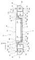
まず、第1実施形態に係るバッテリユニット搭載構造10について説明する。図1、図2に示されるように、バッテリユニット搭載構造10を備えたハイブリッド自動車や電気自動車等の車両12は、車室のフロアを構成する金属製のフロアパネル14を有している。なお、図3に示されるように、フロアパネル14の車幅方向外側部分は、車体上方側へ向かって屈曲され、更に車幅方向外側へ向かって屈曲されており、その車幅方向外側へ向かって屈曲された車幅方向外側端部がフランジ部14Aとされている。
<First Embodiment>
First, the battery
また、図1〜図3に示されるように、フロアパネル14(フランジ部14A)の車幅方向外側には、車体前後方向に延在する左右一対の車体骨格部材としての金属製のロッカ20が配置されている。ロッカ20は、断面略ハット型形状のアウタパネル22と断面略ハット型形状のインナパネル26とを有しており、アウタパネル22のフランジ部24とインナパネル26のフランジ部28とが溶接等によって接合されることで、閉断面形状に形成されている。
In addition, as shown in FIGS. 1 to 3, a
ロッカ20の車幅方向内側(インナパネル26)には、断面略「C」字状とされて車体前後方向に延在する左右一対のサイドメンバとしてのリアサイドメンバ30が結合されている。リアサイドメンバ30は、アッパパネル32とアンダパネル34とを有しており、アッパパネル32の車幅方向外側端部32Aが、インナパネル26の上壁26Aに溶接等によって接合されている。そして、アンダパネル34の車幅方向外側端部34Aが、インナパネル26の下壁26Bに溶接等によって接合されている。
A
また、アッパパネル32の車幅方向内側端部には、フランジ部33が一体に形成されており、アンダパネル34の上部側で、かつ車幅方向内側端部には、フロアパネル14のフランジ部14Aを挟んでフランジ部33に接合されるフランジ部35が一体に形成されている。これにより、リアサイドメンバ30とロッカ20のインナパネル26とで閉断面形状が形成されるとともに、フロアパネル14のフランジ部14Aが、リアサイドメンバ30を介してロッカ20に固定される構成になっている。
Further, a
また、図1、図2に示されるように、フロアパネル14は、車幅方向中央部に車体上方側へ凸状とされて車体前後方向に延在するトンネル部16を有している。そして、リアサイドメンバ30の車体前方側におけるフロアパネル14の上面には、車幅方向に延在して左右のロッカ20(インナパネル26)同士を連結する断面略ハット型形状のリアクロスメンバ36が接合されている。
As shown in FIGS. 1 and 2, the
また、リアクロスメンバ36の車体後方側におけるフロアパネル14の上面で、かつ左右のリアサイドメンバ30(ロッカ20)の間には、バッテリユニット40が配置されるようになっている。バッテリユニット40は、蓄電パック、電池パック又はHV(ハイブリッド)バッテリとも呼ばれるものであり、車幅方向が長手方向とされた略直方体形状に形成されている。
Further, a
そして、リアクロスメンバ36の車体後方側におけるフロアパネル14の上面には、バッテリユニット40の下部とほぼ合致する形状の凹部18が形成されている。したがって、バッテリユニット40は、その下部が凹部18に嵌合されることで、フロアパネル14の上面側に位置ずれ等が規制された状態で配置される構成になっている。なお、バッテリユニット40の車体上方側には、リアサイドメンバ30に支持されたリアシート38(図3参照)が配置されるようになっている。
A
また、図1〜図3に示されるように、バッテリユニット40の下面42には、車幅方向に延在する補強部材としてのロッド部材50が設けられている。ロッド部材50は、円形のパイプ状に形成されており、平面視(底面視)で、バッテリユニット40とオーバーラップする位置(例えば下面42の車体前後方向略中央部)に、複数(例えば2個)のブラケット48によって結合固定されている。
Moreover, as FIG. 1-3 shows, the
各ブラケット48は、断面略「U」字状に形成されており、ロッド部材50の下方側から、そのロッド部材50の外周面に所定の圧力で嵌められて接合され、前後に延在するフランジ部48Aが、バッテリユニット40の下面42にボルト締結されることにより、ロッド部材50をバッテリユニット40の下面42に固定するようになっている。これにより、ロッド部材50は、バッテリユニット40に対して相対的に車幅方向へ移動不能となっている。
Each
また、バッテリユニット40の下面42に固定されて、フロアパネル14の凹部18内に設けられたロッド部材50は、車体前後方向及び車幅方向から見て、リアサイドメンバ30及びロッカ20(フランジ部24、28を除く)と車体上下方向でオーバーラップする位置に配置されている。つまり、ロッド部材50は、車体前後方向及び車幅方向から見て、リアサイドメンバ30及びロッカ20(フランジ部24、28を除く)から車体上方側及び車体下方側へ突出しない位置に配置されている。
Further, the
更に、ロッド部材50は、その車幅方向の長さが、バッテリユニット40の車幅方向の長さよりも長く形成されている。すなわち、ロッド部材50の車幅方向外側端部52は、それぞれバッテリユニット40の側面44(車幅方向外側端部)から車幅方向外側へ左右同じ長さで突出されるようになっている。これにより、バッテリユニット40の側面44とフロアパネル14の車体上方側へ向かって屈曲された車幅方向外側部分との間に、左右同じ大きさの空隙Sが形成される構成になっている。
Further, the
なお、図示のロッド部材50は、円形のパイプ状に形成されているが、これに限定されるものではなく、例えば角形のパイプ状等に形成されていてもよい。また、ロッド部材50をバッテリユニット40の下面42に結合するブラケット48は、図示の2個に限定されるものではない。更に、ロッド部材50は、溶接等によって、バッテリユニット40の下面42に直接接合されて固定される構成とされていてもよい。
The illustrated
以上のような構成とされた第1実施形態に係るバッテリユニット搭載構造10において、次にその作用について説明する。すなわち、図4に示されるように、例えば鉛直方向に延在する円柱状(又は円筒状)の金属製のポール(障壁)Pに車両12が側面衝突した場合の作用について説明する。
Next, the operation of the battery
図4に示されるように、ポールPに車両12が側面衝突したときには、その衝突側のロッカ20及びリアサイドメンバ30に対して車幅方向内側へ向かう過大な衝突荷重Fが入力される。ロッカ20及びリアサイドメンバ30に対して車幅方向外側から衝突荷重Fが入力されると、ロッカ20及びリアサイドメンバ30は、車幅方向内側へ塑性変形しつつ移動して、その入力された衝突荷重Fの一部をエネルギー吸収し、残りの衝突荷重をバッテリユニット40に固定されたロッド部材50に伝達する。
As shown in FIG. 4, when the
ロッド部材50は、バッテリユニット40の車幅方向の長さよりも長く車幅方向に延在されている(ロッド部材50の長さがバッテリユニット40の車幅方向の長さよりも長くされている)ため、車両12の側面衝突時には、バッテリユニット40の側面44よりも先に、その車幅方向外側端部52へ衝突荷重が伝達される。また、ロッド部材50は、円形のパイプ状に形成されているため、その軸方向の剛性及び強度が高い。
The
よって、ロッド部材50に車幅方向外側から衝突荷重が伝達されると、ロッド部材50は、その軸方向で衝突荷重を受け止めるとともに、その軸方向(車幅方向)に移動し、衝突側とは反対側のリアサイドメンバ30を車幅方向内側から押し潰す。これにより、衝突側のロッカ20及びリアサイドメンバ30に入力された衝突荷重を反対側のリアサイドメンバ30及びロッカ20に伝達させて分散させる(エネルギー吸収させる)ことができ、バッテリユニット40に衝突荷重が入力されるのを抑制又は防止することができる。
Therefore, when a collision load is transmitted to the
つまり、車幅方向外側から入力される衝突荷重によってバッテリユニット40が損傷するのを効果的に抑制することができる(バッテリユニット40を保護することができる)。特に、ロッド部材50は、バッテリユニット40に固定されているので、ロッド部材50が衝突側から離れる方向(車幅方向)に移動すると、バッテリユニット40も衝突側から離れる方向に移動する。したがって、バッテリユニット40に衝突荷重が入力されるのをより一層抑制又は防止することができる。
That is, it is possible to effectively prevent the
更に、ロッド部材50は、リアサイドメンバ30及びロッカ20と車体上下方向にオーバーラップする位置に配置されているので、衝突側のロッカ20及びリアサイドメンバ30に入力された衝突荷重を反対側のリアサイドメンバ30及びロッカ20に伝達させ易い。つまり、このような構成であると、衝突側のロッカ20及びリアサイドメンバ30に入力された衝突荷重を反対側のリアサイドメンバ30及びロッカ20に効率よく伝達させて分散させることができる。したがって、車幅方向外側から入力される衝突荷重によってバッテリユニット40が損傷するのをより効果的に抑制することができる。
Further, since the
また、本実施形態に係るバッテリユニット搭載構造10は、バッテリユニット40の下面42にロッド部材50を固定するだけでよいので、容易に構成することができ、例えばリアクロスメンバ36の強度を上げて対応するよりも重量増加を抑制することができる。よって、車両12の燃費性能を向上させることができる。また、フロアパネル14に対してバッテリユニット40を配置する際にも、ロッド部材50を配置できるスペースが形成されるように、凹部18の形状を設定するだけでよいので、フロアパネル14の上面側における各部のレイアウトに制限を受けることがない。
Further, the battery
<第2実施形態>
次に、第2実施形態に係るバッテリユニット搭載構造10について説明する。なお、上記第1実施形態と同等の部位には、同じ符号を付して詳細な説明(共通する作用も含む)は適宜省略する。
Second Embodiment
Next, the battery
図5、図6に示されるように、第2実施形態に係るバッテリユニット搭載構造10は、左右のリアサイドメンバ30のアッパパネル32と、ロッド部材50の車幅方向外側端部52と、を連結する左右一対のガセット54を有している点だけが、上記第1実施形態と異なっている。
As shown in FIGS. 5 and 6, the battery
各ガセット54は、断面略「Z」字状に屈曲成形されており、その上部側である車幅方向外側端部54Aが、リアサイドメンバ30のアッパパネル32の上面にボルト締結等によって結合されている。そして、各ガセット54の下部側である車幅方向内側端部54Bにおける車体後方側が、ロッド部材50の車幅方向外側端部52の上面に溶接等によって接合されている。
Each
したがって、図4に示したように、車両12がポールPに側面衝突したときには、衝突側のリアサイドメンバ30からガセット54を介してロッド部材50へ早期(衝突初期)に衝突荷重が伝達される。そして、ロッド部材50に伝達された衝突荷重は、衝突側とは反対側のガセット54を介して、その反対側のリアサイドメンバ30へ早期に伝達されて分散される。
Therefore, as shown in FIG. 4, when the
つまり、このようなガセット54を設けると、衝突側のロッカ20及びリアサイドメンバ30に入力された衝突荷重を反対側のリアサイドメンバ30及びロッカ20へ早期に伝達させて分散させることができるため、そのエネルギー吸収効率を向上させることができる。よって、バッテリユニット40に衝突荷重が入力されるのをより一層抑制又は防止することができ、車幅方向外側から入力される衝突荷重によってバッテリユニット40が損傷するのをより効果的に抑制することができる。
That is, if such a
なお、図5に示されるように、各ガセット54の車幅方向内側端部54Bにおける車体前方側が、リアクロスメンバ36の上壁36Aにボルト締結等によって接合されている。したがって、衝突側のリアサイドメンバ30からガセット54を介してリアクロスメンバ36へも早期(衝突初期)に衝突荷重を伝達させて分散させることができる。また、このようなガセット54を設けると、バッテリユニット40の下面42における車幅方向両端部をガセット54によって保持することができる。
As shown in FIG. 5, the vehicle body front side at the vehicle width direction inner
<第3実施形態>
最後に、第3実施形態に係るバッテリユニット搭載構造10について説明する。なお、上記第1実施形態及び第2実施形態と同等の部位には、同じ符号を付して詳細な説明(共通する作用も含む)は適宜省略する。
<Third Embodiment>
Finally, the battery
図7に示されるように、第3実施形態に係るバッテリユニット搭載構造10は、バッテリユニット40の上面46に、ロッド部材50が、平面視で、そのバッテリユニット40とオーバーラップする位置(例えば上面46の車体前後方向略中央部)に、複数(例えば2個)のブラケット48によって結合固定されている点だけが、上記第2実施形態と異なっている。
As shown in FIG. 7, the battery
したがって、図4に示したように、車両12がポールPに側面衝突したときには、上記第2実施形態と同様に、衝突側のロッカ20及びリアサイドメンバ30に入力された衝突荷重を反対側のリアサイドメンバ30及びロッカ20へ早期(衝突初期)に伝達させて分散させることができ、そのエネルギー吸収効率を向上させることができる。
Therefore, as shown in FIG. 4, when the
よって、バッテリユニット40に衝突荷重が入力されるのをより一層抑制又は防止することができ、車幅方向外側から入力される衝突荷重によってバッテリユニット40が損傷するのをより効果的に抑制することができる。また、この第3実施形態によれば、リアシート38の位置を第1実施形態及び第2実施形態におけるリアシート38の位置よりも低位に配置することができる。
Therefore, it is possible to further suppress or prevent the collision load from being input to the
以上、本実施形態に係るバッテリユニット搭載構造10について、図面を基に説明したが、本実施形態に係るバッテリユニット搭載構造10は、図示のものに限定されるものではなく、本発明の要旨を逸脱しない範囲内において、適宜設計変更可能なものである。例えば、ロッド部材50は、図示の1本に限定されるものではなく、車体前後方向に複数本(例えば2本)設けられる構成とされていてもよい。
The battery
また、ロッド部材50は、バッテリユニット40の下面42又は上面46に固定されていなくてもよい。すなわち、ロッド部材50は、バッテリユニット40に対して車幅方向に移動可能に取り付けられていてもよい。更に、バッテリユニット40の側面44とフロアパネル14の車体上方側へ向かって屈曲された車幅方向外側部分との間に形成される空隙Sの大きさが、左右で異なる構成とされていてもよい。
Further, the
また、左右一対のガセット54が設けられない第1実施形態において、ロッド部材50の長手方向略中央部とリアクロスメンバ36の長手方向略中央部とを図示しない連結部材で連結して、ロッド部材50に伝達された衝突荷重がリアクロスメンバ36へも伝達されて分散される構成にしてもよい。
Further, in the first embodiment in which the pair of left and
また、ロッカ20の車幅方向内側にリアサイドメンバ30が設けられない構成とされていてもよい。この場合、ロッカ20のインナパネル26の上壁26Aに、フロアパネル14のフランジ部14Aが接合される構成とされていればよい。また、この場合には、ガセット54の車幅方向外側端部54Aも、ロッカ20のインナパネル26の上壁26Aに結合される構成とされていればよい。
Further, the
但し、ロッカ20の車幅方向内側にリアサイドメンバ30が設けられていると、車幅方向外側から入力された衝突荷重をリアサイドメンバ30によってエネルギー吸収することができる利点がある。また、本実施形態に係るバッテリユニット搭載構造10によれば、車両12がポールPなどの局部変形を引き起こす障壁に側面衝突した場合に限らず、例えば平面状の障壁に車両12が高速で側面衝突した場合でも、同様の作用効果を得ることができる。
However, when the
10 バッテリユニット搭載構造
20 ロッカ(車体骨格部材)
30 リアサイドメンバ(サイドメンバ)
40 バッテリユニット
50 ロッド部材(補強部材)
54 ガセット
10 Battery
30 Rear side member (side member)
40
54 Gusset
Claims (3)
車体前後方向に延在するとともに前記左右一対の車体骨格部材の車幅方向内側にそれぞれ結合された左右一対のサイドメンバと、
前記左右一対のサイドメンバの間に配置されたバッテリユニットと、
前記バッテリユニットの車幅方向の長さよりも長く車幅方向に延在され、前記バッテリユニットの下面又は上面で、かつ平面視で前記バッテリユニットと車体前後方向略中央部でオーバーラップするとともに側面視で前記車体骨格部材と車体上下方向でオーバーラップする位置に設けられ、車幅方向両端部が前記サイドメンバの車幅方向内側に配置されたパイプ状の補強部材と、
を備えたバッテリユニット搭載構造。 A pair of left and right vehicle body skeleton members extending in the vehicle longitudinal direction at the vehicle width direction outside;
A pair of left and right side members extending in the longitudinal direction of the vehicle body and coupled to the inner side in the vehicle width direction of the pair of left and right body frame members,
A battery unit disposed between the pair of left and right side members;
Wherein the vehicle width direction of the battery unit extends in the vehicle width direction longer than the length, side view together with the the lower surface or upper surface of the battery unit, and overlaps with the battery unit and the vehicle body front-rear direction substantially central portion in a plan view A pipe- shaped reinforcing member that is provided at a position overlapping with the vehicle body skeleton member in the vehicle vertical direction, and that both ends in the vehicle width direction are arranged on the inner side in the vehicle width direction of the side member;
Battery unit mounting structure with
Priority Applications (4)
| Application Number | Priority Date | Filing Date | Title |
|---|---|---|---|
| JP2015045046A JP6344270B2 (en) | 2015-03-06 | 2015-03-06 | Battery unit mounting structure |
| EP16156973.6A EP3064389B1 (en) | 2015-03-06 | 2016-02-23 | Battery unit mounting structure |
| US15/052,014 US9517687B2 (en) | 2015-03-06 | 2016-02-24 | Battery unit mounting structure |
| CN201610108926.1A CN105936303B (en) | 2015-03-06 | 2016-02-26 | Secondary battery unit carrying structure |
Applications Claiming Priority (1)
| Application Number | Priority Date | Filing Date | Title |
|---|---|---|---|
| JP2015045046A JP6344270B2 (en) | 2015-03-06 | 2015-03-06 | Battery unit mounting structure |
Publications (2)
| Publication Number | Publication Date |
|---|---|
| JP2016164051A JP2016164051A (en) | 2016-09-08 |
| JP6344270B2 true JP6344270B2 (en) | 2018-06-20 |
Family
ID=55411293
Family Applications (1)
| Application Number | Title | Priority Date | Filing Date |
|---|---|---|---|
| JP2015045046A Expired - Fee Related JP6344270B2 (en) | 2015-03-06 | 2015-03-06 | Battery unit mounting structure |
Country Status (4)
| Country | Link |
|---|---|
| US (1) | US9517687B2 (en) |
| EP (1) | EP3064389B1 (en) |
| JP (1) | JP6344270B2 (en) |
| CN (1) | CN105936303B (en) |
Families Citing this family (35)
| Publication number | Priority date | Publication date | Assignee | Title |
|---|---|---|---|---|
| JP5870992B2 (en) * | 2013-12-25 | 2016-03-01 | トヨタ自動車株式会社 | Battery mounting structure for vehicles |
| JP6535569B2 (en) * | 2015-10-20 | 2019-06-26 | 本田技研工業株式会社 | vehicle |
| US10308290B1 (en) * | 2016-09-20 | 2019-06-04 | Apple Inc. | Vehicle floor and subassemblies thereof |
| JP6475270B2 (en) * | 2017-01-20 | 2019-02-27 | 株式会社Subaru | Car |
| JP6541724B2 (en) * | 2017-07-10 | 2019-07-10 | 株式会社Subaru | Car vehicle |
| US10494034B2 (en) * | 2017-09-25 | 2019-12-03 | Ford Global Technologies, Llc | Vehicle frame assembly |
| JP6937649B2 (en) * | 2017-09-29 | 2021-09-22 | アイシン軽金属株式会社 | Shock absorbing member and shock absorbing structure using it |
| JP6859933B2 (en) * | 2017-11-17 | 2021-04-14 | トヨタ自動車株式会社 | Vehicle battery case and its manufacturing method |
| DE102017010670C5 (en) * | 2017-11-17 | 2022-06-02 | Mercedes-Benz Group AG | Side sill arrangement of a body of an electrically operated motor vehicle |
| CN110027627A (en) * | 2018-01-12 | 2019-07-19 | 丰田自动车株式会社 | Lower vehicle construction |
| JP6954154B2 (en) * | 2018-01-30 | 2021-10-27 | トヨタ自動車株式会社 | Vehicle floor structure |
| JP6655638B2 (en) * | 2018-02-15 | 2020-02-26 | 本田技研工業株式会社 | Body structure |
| JP7048354B2 (en) * | 2018-03-01 | 2022-04-05 | アイシン軽金属株式会社 | Protective structure for in-vehicle objects |
| JP6996352B2 (en) * | 2018-03-06 | 2022-01-17 | トヨタ自動車株式会社 | Vehicle lower body structure |
| JP6689911B2 (en) * | 2018-05-25 | 2020-04-28 | 本田技研工業株式会社 | Underbody structure |
| JP7067334B2 (en) * | 2018-07-18 | 2022-05-16 | トヨタ自動車株式会社 | Vehicle rear structure |
| JP7014075B2 (en) * | 2018-07-19 | 2022-02-01 | トヨタ自動車株式会社 | Body side structure |
| JP2020015356A (en) * | 2018-07-24 | 2020-01-30 | トヨタ自動車株式会社 | Vehicle lower part structure |
| US10494030B1 (en) * | 2018-08-20 | 2019-12-03 | Ford Global Technologies, Llc | Collapsible battery pack support assembly and supporting method |
| CN112638681B (en) * | 2018-08-28 | 2023-09-19 | 本田技研工业株式会社 | Configuration structure of storage battery pack |
| JP7014107B2 (en) * | 2018-09-05 | 2022-02-01 | トヨタ自動車株式会社 | Battery pack support structure |
| JP2020045017A (en) * | 2018-09-20 | 2020-03-26 | トヨタ自動車株式会社 | Vehicle body lower part structure |
| FR3088031B1 (en) * | 2018-11-07 | 2021-01-15 | Renault Sas | PROTECTION DEVICE FOR A VEHICLE POWER SUPPLY BATTERY |
| US10720620B1 (en) * | 2019-01-15 | 2020-07-21 | Ford Global Technologies, Llc | High voltage battery pack mounting systems for providing load path management during impact loading events |
| JP7360834B2 (en) | 2019-07-12 | 2023-10-13 | メルセデス・ベンツ グループ アクチェンゲゼルシャフト | electric truck |
| GB2585693B (en) * | 2019-07-12 | 2021-11-03 | Jaguar Land Rover Ltd | A battery mounting arrangement and a vehicle |
| FR3107011A1 (en) * | 2020-02-08 | 2021-08-13 | Psa Automobiles Sa | VEHICLE CHASSIS WITH BASE, BATTERY BOX AND REINFORCEMENT STRUCTURE |
| JP2021123321A (en) * | 2020-02-10 | 2021-08-30 | トヨタ自動車株式会社 | vehicle |
| US11548361B2 (en) * | 2020-02-12 | 2023-01-10 | Ford Global Technologies, Llc | Support structures for vehicle frame mounted battery packs |
| JP7413844B2 (en) * | 2020-03-03 | 2024-01-16 | トヨタ自動車株式会社 | Vehicle undercarriage structure |
| WO2022036364A1 (en) | 2020-08-12 | 2022-02-17 | Trova Commercial Vehicles Inc | Battery energy storage systems mounting |
| JP7369681B2 (en) * | 2020-11-11 | 2023-10-26 | 本田技研工業株式会社 | Vehicles equipped with battery packs |
| JP7359799B2 (en) * | 2021-03-26 | 2023-10-11 | トヨタ自動車株式会社 | vehicle |
| JP7450320B2 (en) | 2022-03-09 | 2024-03-15 | ダイハツ工業株式会社 | vehicle structure |
| FR3141133A1 (en) * | 2022-10-19 | 2024-04-26 | Psa Automobiles Sa | Chassis for a motor vehicle comprising a mechanical reinforcement linked to a spar and facing one edge of a heel board |
Family Cites Families (23)
| Publication number | Priority date | Publication date | Assignee | Title |
|---|---|---|---|---|
| JP5141026B2 (en) | 2006-02-27 | 2013-02-13 | トヨタ自動車株式会社 | In-vehicle structure of power storage pack |
| JP4858183B2 (en) * | 2007-01-22 | 2012-01-18 | 日産自動車株式会社 | Lower body structure |
| JP4308285B2 (en) | 2007-07-17 | 2009-08-05 | 本田技研工業株式会社 | Subframe structure |
| JP4319239B2 (en) | 2008-02-07 | 2009-08-26 | 本田技研工業株式会社 | Hybrid vehicle |
| DE102009025430B3 (en) * | 2009-06-16 | 2011-02-17 | Benteler Automobiltechnik Gmbh | Motor vehicle with an electric drive |
| KR20120012655A (en) * | 2010-08-02 | 2012-02-10 | (주)브이이엔에스 | Electric vehicle |
| JP5434860B2 (en) | 2010-09-17 | 2014-03-05 | トヨタ車体株式会社 | Battery pack mounting structure in vehicle |
| EP2620353B1 (en) * | 2010-11-10 | 2015-09-02 | Honda Motor Co., Ltd. | Automobile floor structure |
| JP5541100B2 (en) | 2010-11-10 | 2014-07-09 | 三菱自動車工業株式会社 | Battery pack tray |
| DE112011104518T5 (en) * | 2010-12-24 | 2013-10-24 | Honda Motor Co., Ltd. | Vehicle body structure |
| US20120175177A1 (en) * | 2011-01-07 | 2012-07-12 | Ford Global Technologies Llc | Vehicle Battery Pack Frame |
| DE102011002650B4 (en) * | 2011-01-13 | 2023-12-07 | Ford Global Technologies, Llc | motor vehicle |
| DE102011051698A1 (en) * | 2011-07-08 | 2013-01-10 | Thyssenkrupp Steel Europe Ag | Floor structure for a vehicle |
| CN103987552B (en) * | 2011-10-11 | 2018-04-06 | 丰田自动车株式会社 | The carrying structure of electrical storage device |
| JP5411235B2 (en) * | 2011-11-15 | 2014-02-12 | 本田技研工業株式会社 | Lower body structure of automobile |
| US8950536B2 (en) * | 2011-12-21 | 2015-02-10 | Ford Global Technologies, Llc | Modular battery assembly support and seals |
| DE102012203892A1 (en) * | 2012-03-13 | 2013-09-19 | Bayerische Motoren Werke Aktiengesellschaft | Motor vehicle, particularly passenger motor vehicle, has energy storage that is centrally attached to lower side of floor structure, where energy storage is supporting autobody component and comprises supporting housing |
| JP6035916B2 (en) * | 2012-07-05 | 2016-11-30 | スズキ株式会社 | Car body rear structure |
| JP5935569B2 (en) * | 2012-07-25 | 2016-06-15 | スズキ株式会社 | Battery unit mounting structure for vehicles |
| DE102012019922B4 (en) * | 2012-10-11 | 2023-03-02 | Volkswagen Aktiengesellschaft | Battery arrangement in a vehicle |
| JP6197363B2 (en) * | 2013-05-20 | 2017-09-20 | 日産自動車株式会社 | Vehicle with battery |
| JP5645147B2 (en) | 2013-05-20 | 2014-12-24 | 三菱自動車工業株式会社 | Auto body structure |
| JP5900480B2 (en) | 2013-05-24 | 2016-04-06 | トヨタ自動車株式会社 | Vehicle battery mounting structure |
-
2015
- 2015-03-06 JP JP2015045046A patent/JP6344270B2/en not_active Expired - Fee Related
-
2016
- 2016-02-23 EP EP16156973.6A patent/EP3064389B1/en active Active
- 2016-02-24 US US15/052,014 patent/US9517687B2/en active Active
- 2016-02-26 CN CN201610108926.1A patent/CN105936303B/en not_active Expired - Fee Related
Also Published As
| Publication number | Publication date |
|---|---|
| EP3064389B1 (en) | 2021-01-20 |
| CN105936303A (en) | 2016-09-14 |
| CN105936303B (en) | 2018-06-26 |
| JP2016164051A (en) | 2016-09-08 |
| US20160257187A1 (en) | 2016-09-08 |
| EP3064389A1 (en) | 2016-09-07 |
| US9517687B2 (en) | 2016-12-13 |
Similar Documents
| Publication | Publication Date | Title |
|---|---|---|
| JP6344270B2 (en) | Battery unit mounting structure | |
| JP6421766B2 (en) | Frame car skeleton structure | |
| US9290138B2 (en) | Vehicle front section structure | |
| JP5907126B2 (en) | Auto body front structure | |
| JP5907147B2 (en) | Lower body structure | |
| JP5831489B2 (en) | Vehicle front structure | |
| JP6557290B2 (en) | Body front structure | |
| JP5769092B2 (en) | Power supply protection frame structure | |
| JP6452044B2 (en) | Rear body structure of automobile | |
| JP6137105B2 (en) | Battery drive battery mounting structure | |
| JP5790785B2 (en) | Vehicle front structure | |
| JP2019026084A (en) | Vehicle front structure | |
| JP6284041B2 (en) | Vehicle battery mounting structure | |
| US10343721B2 (en) | Front vehicle body reinforcing structure | |
| JP5831246B2 (en) | Body front structure | |
| JP6575317B2 (en) | Vehicle front structure | |
| JP5803819B2 (en) | Vehicle front structure | |
| JP2010115946A (en) | Vehicle body front part structure | |
| JP2014012428A (en) | Vehicle body front structure | |
| JP5902636B2 (en) | Body front structure | |
| JP6213171B2 (en) | Vehicle floor structure | |
| JP5723562B2 (en) | Auto body front structure | |
| JP6024808B2 (en) | Auto body front structure | |
| JP6120447B2 (en) | Auto body structure | |
| JP6458711B2 (en) | Fuel tank protection structure |
Legal Events
| Date | Code | Title | Description |
|---|---|---|---|
| A621 | Written request for application examination |
Free format text: JAPANESE INTERMEDIATE CODE: A621 Effective date: 20160824 |
|
| A977 | Report on retrieval |
Free format text: JAPANESE INTERMEDIATE CODE: A971007 Effective date: 20170511 |
|
| A131 | Notification of reasons for refusal |
Free format text: JAPANESE INTERMEDIATE CODE: A131 Effective date: 20170516 |
|
| A521 | Request for written amendment filed |
Free format text: JAPANESE INTERMEDIATE CODE: A523 Effective date: 20170714 |
|
| A131 | Notification of reasons for refusal |
Free format text: JAPANESE INTERMEDIATE CODE: A131 Effective date: 20170926 |
|
| A521 | Request for written amendment filed |
Free format text: JAPANESE INTERMEDIATE CODE: A523 Effective date: 20171124 |
|
| TRDD | Decision of grant or rejection written | ||
| A01 | Written decision to grant a patent or to grant a registration (utility model) |
Free format text: JAPANESE INTERMEDIATE CODE: A01 Effective date: 20180424 |
|
| A61 | First payment of annual fees (during grant procedure) |
Free format text: JAPANESE INTERMEDIATE CODE: A61 Effective date: 20180507 |
|
| R151 | Written notification of patent or utility model registration |
Ref document number: 6344270 Country of ref document: JP Free format text: JAPANESE INTERMEDIATE CODE: R151 |
|
| LAPS | Cancellation because of no payment of annual fees |