JP6314371B2 - MOBILE BODY SYSTEM AND MOBILE BODY DRIVING METHOD - Google Patents

MOBILE BODY SYSTEM AND MOBILE BODY DRIVING METHOD Download PDF

Info

Publication number
JP6314371B2
JP6314371B2 JP2013089408A JP2013089408A JP6314371B2 JP 6314371 B2 JP6314371 B2 JP 6314371B2 JP 2013089408 A JP2013089408 A JP 2013089408A JP 2013089408 A JP2013089408 A JP 2013089408A JP 6314371 B2 JP6314371 B2 JP 6314371B2
Authority
JP
Japan
Prior art keywords
motor
magnet
control unit
section
irregular section
Prior art date
Legal status (The legal status is an assumption and is not a legal conclusion. Google has not performed a legal analysis and makes no representation as to the accuracy of the status listed.)
Active
Application number
JP2013089408A
Other languages
Japanese (ja)
Other versions
JP2014217076A (en
JP2014217076A5 (en
Inventor
康武 山田
康武 山田
良行 東
良行 東
Current Assignee (The listed assignees may be inaccurate. Google has not performed a legal analysis and makes no representation or warranty as to the accuracy of the list.)
Murata Machinery Ltd
Original Assignee
Murata Machinery Ltd
Priority date (The priority date is an assumption and is not a legal conclusion. Google has not performed a legal analysis and makes no representation as to the accuracy of the date listed.)
Filing date
Publication date
Priority to JP2013089408A priority Critical patent/JP6314371B2/en
Application filed by Murata Machinery Ltd filed Critical Murata Machinery Ltd
Priority to PCT/JP2014/059843 priority patent/WO2014175032A1/en
Priority to CN201480022186.9A priority patent/CN105142970B/en
Priority to EP14788736.8A priority patent/EP2990259B1/en
Priority to US14/785,779 priority patent/US9871478B2/en
Priority to KR1020157030304A priority patent/KR101900721B1/en
Priority to SG11201508622YA priority patent/SG11201508622YA/en
Priority to TW103113855A priority patent/TWI606941B/en
Publication of JP2014217076A publication Critical patent/JP2014217076A/en
Priority to IL242191A priority patent/IL242191B/en
Publication of JP2014217076A5 publication Critical patent/JP2014217076A5/ja
Application granted granted Critical
Publication of JP6314371B2 publication Critical patent/JP6314371B2/en
Active legal-status Critical Current
Anticipated expiration legal-status Critical

Links

Images

Classifications

    • HELECTRICITY
    • H02GENERATION; CONVERSION OR DISTRIBUTION OF ELECTRIC POWER
    • H02PCONTROL OR REGULATION OF ELECTRIC MOTORS, ELECTRIC GENERATORS OR DYNAMO-ELECTRIC CONVERTERS; CONTROLLING TRANSFORMERS, REACTORS OR CHOKE COILS
    • H02P8/00Arrangements for controlling dynamo-electric motors of the kind having motors rotating step by step
    • H02P8/005Arrangements for controlling dynamo-electric motors of the kind having motors rotating step by step of linear motors
    • BPERFORMING OPERATIONS; TRANSPORTING
    • B60VEHICLES IN GENERAL
    • B60LPROPULSION OF ELECTRICALLY-PROPELLED VEHICLES; SUPPLYING ELECTRIC POWER FOR AUXILIARY EQUIPMENT OF ELECTRICALLY-PROPELLED VEHICLES; ELECTRODYNAMIC BRAKE SYSTEMS FOR VEHICLES IN GENERAL; MAGNETIC SUSPENSION OR LEVITATION FOR VEHICLES; MONITORING OPERATING VARIABLES OF ELECTRICALLY-PROPELLED VEHICLES; ELECTRIC SAFETY DEVICES FOR ELECTRICALLY-PROPELLED VEHICLES
    • B60L13/00Electric propulsion for monorail vehicles, suspension vehicles or rack railways; Magnetic suspension or levitation for vehicles
    • B60L13/03Electric propulsion by linear motors
    • HELECTRICITY
    • H02GENERATION; CONVERSION OR DISTRIBUTION OF ELECTRIC POWER
    • H02KDYNAMO-ELECTRIC MACHINES
    • H02K11/00Structural association of dynamo-electric machines with electric components or with devices for shielding, monitoring or protection
    • H02K11/0094Structural association with other electrical or electronic devices
    • HELECTRICITY
    • H02GENERATION; CONVERSION OR DISTRIBUTION OF ELECTRIC POWER
    • H02KDYNAMO-ELECTRIC MACHINES
    • H02K41/00Propulsion systems in which a rigid body is moved along a path due to dynamo-electric interaction between the body and a magnetic field travelling along the path
    • H02K41/02Linear motors; Sectional motors
    • H02K41/03Synchronous motors; Motors moving step by step; Reluctance motors
    • H02K41/031Synchronous motors; Motors moving step by step; Reluctance motors of the permanent magnet type
    • HELECTRICITY
    • H02GENERATION; CONVERSION OR DISTRIBUTION OF ELECTRIC POWER
    • H02PCONTROL OR REGULATION OF ELECTRIC MOTORS, ELECTRIC GENERATORS OR DYNAMO-ELECTRIC CONVERTERS; CONTROLLING TRANSFORMERS, REACTORS OR CHOKE COILS
    • H02P6/00Arrangements for controlling synchronous motors or other dynamo-electric motors using electronic commutation dependent on the rotor position; Electronic commutators therefor
    • H02P6/14Electronic commutators
    • H02P6/15Controlling commutation time
    • HELECTRICITY
    • H02GENERATION; CONVERSION OR DISTRIBUTION OF ELECTRIC POWER
    • H02PCONTROL OR REGULATION OF ELECTRIC MOTORS, ELECTRIC GENERATORS OR DYNAMO-ELECTRIC CONVERTERS; CONTROLLING TRANSFORMERS, REACTORS OR CHOKE COILS
    • H02P6/00Arrangements for controlling synchronous motors or other dynamo-electric motors using electronic commutation dependent on the rotor position; Electronic commutators therefor
    • H02P6/14Electronic commutators
    • H02P6/16Circuit arrangements for detecting position
    • HELECTRICITY
    • H02GENERATION; CONVERSION OR DISTRIBUTION OF ELECTRIC POWER
    • H02KDYNAMO-ELECTRIC MACHINES
    • H02K2213/00Specific aspects, not otherwise provided for and not covered by codes H02K2201/00 - H02K2211/00
    • H02K2213/03Machines characterised by numerical values, ranges, mathematical expressions or similar information
    • HELECTRICITY
    • H02GENERATION; CONVERSION OR DISTRIBUTION OF ELECTRIC POWER
    • H02KDYNAMO-ELECTRIC MACHINES
    • H02K29/00Motors or generators having non-mechanical commutating devices, e.g. discharge tubes or semiconductor devices
    • H02K29/03Motors or generators having non-mechanical commutating devices, e.g. discharge tubes or semiconductor devices with a magnetic circuit specially adapted for avoiding torque ripples or self-starting problems

Description

本発明は、移動体が移動経路に沿って移動する移動体システム、及び移動体の駆動方法に関する。   The present invention relates to a moving body system in which a moving body moves along a moving path, and a driving method of the moving body.

従来から、リニアモータを利用した移動体システムが知られている。この移動体システムにおいて、地上二次式リニアモータを利用したものがある。地上二次式は、可動子(移動体)側にリニアモータが搭載され、固定子(軌道)側に磁石が配置される方式である。この種の移動体システムとして、例えば、特許文献1に記載されているように、軌道(移動経路)上にS極とN極の磁石が交互に配置され、リニアモータが搭載された移動体が軌道に沿って移動する移動体システムが知られている。   Conventionally, a mobile system using a linear motor is known. Some of these mobile systems utilize a ground-type secondary linear motor. The ground secondary type is a system in which a linear motor is mounted on the mover (moving body) side and a magnet is arranged on the stator (track) side. As this type of moving body system, for example, as described in Patent Document 1, a moving body in which S-pole and N-pole magnets are alternately arranged on a track (movement path) and a linear motor is mounted is provided. A mobile system that moves along a trajectory is known.

特開2006−27421号公報JP 2006-27421 A

上記した特許文献1に記載された移動体システムのように、軌道上にS極とN極の磁石が交互に配置される場合は、軌道長(すなわち移動経路の距離)が磁石のピッチの整数倍でなければ、軌道上の磁石の間に隙間が生じる。そして、軌道上の磁石の間に隙間が生じた場合は、磁石による磁極とリニアモータの電気角とで位相がずれてしまう。このため、磁石による磁極とリニアモータの電気角との同期がとれなくなり、リニアモータを正常に駆動することができなくなる。   When the S pole and N pole magnets are alternately arranged on the track as in the mobile body system described in Patent Document 1 described above, the track length (that is, the distance of the moving path) is an integer of the magnet pitch. If not doubled, there will be a gap between the magnets on the track. And when a clearance gap arises between the magnets on a track | orbit, a phase will shift | deviate with the magnetic pole by a magnet, and the electrical angle of a linear motor. For this reason, the magnetic pole by the magnet and the electrical angle of the linear motor cannot be synchronized, and the linear motor cannot be driven normally.

また、軌道上の磁石の間に隙間が生じないように、磁石のピッチを変更して並べることも考えられる。しかし、磁石のピッチは予め決められていることが多いため、磁石のピッチを変更することは容易ではない。また、磁石のピッチを変更した場合は、リニアモータの推力(推進力)が低下するなどの問題が発生する。   It is also conceivable to arrange the magnets by changing the pitch of the magnets so that no gap is generated between the magnets on the track. However, since the magnet pitch is often determined in advance, it is not easy to change the magnet pitch. Moreover, when the pitch of the magnet is changed, problems such as a reduction in the thrust (propulsive force) of the linear motor occur.

本発明は、前述した事情に鑑みてなされたものであり、移動経路の距離を磁石のピッチに制限されない移動体システム、及び移動体の駆動方法を提供することを目的とする。   The present invention has been made in view of the above-described circumstances, and an object thereof is to provide a moving body system in which the distance of the moving path is not limited by the pitch of the magnet, and a driving method of the moving body.

上記目的を達成するために、本発明では、S極とN極の磁石を交互に配置した移動経路と、この移動経路に沿って移動する移動体とを備える移動体システムであって、移動体は、移動方向において異なる位置に配置される複数のモータと、複数のモータの駆動を制御する駆動制御部と、を有し、複数のモータのうちの一のモータが磁石の磁極の配置が規則的でない不規則区間に位置したときに、一のモータ以外のモータのうちの少なくとも1つのモータが不規則区間でない区間に位置し、駆動制御部は、不規則区間に位置するモータの駆動を停止することを特徴とする。
In order to achieve the above object, the present invention provides a moving body system including a moving path in which S-pole and N-pole magnets are alternately arranged, and a moving body that moves along the moving path. Has a plurality of motors arranged at different positions in the moving direction and a drive control unit for controlling the driving of the plurality of motors, and one of the plurality of motors has a regular arrangement of magnetic poles of magnets. When located in an irregular section, at least one of the motors other than the one motor is located in a section that is not an irregular section, and the drive control unit stops driving the motor located in the irregular section. characterized in that it.

また、不規則区間は、磁石が配置されていない区間であってもよく、不規則区間は、S極とN極の磁石が交互に配置されていない区間であってもよい。また、不規則区間は、複数のモータのうちの移動方向における両端に配置されるモータ間の距離よりも短くてもよい
The irregular section may be a section in which no magnet is arranged, and the irregular section may be a section in which S-pole and N-pole magnets are not arranged alternately. Further, the irregular section may be shorter than the distance between the motors arranged at both ends in the movement direction among the plurality of motors .

また、移動体は、不規則区間を検出する検出部を有し、駆動制御部は、検出部による不規則区間の検出に基づいてモータの駆動を停止するように構成してもよい。また、検出部は、不規則区間に加えて、磁石の磁極の配置が規則的である規則区間を検出し、駆動制御部は、検出部が不規則区間を検出した後に規則区間を検出した場合に、停止していたモータの駆動を再開するものでもよい。また、検出部は、磁石を検出することにより、不規則区間に加えて、磁石の磁極の配置が規則的である規則区間を検出し、駆動制御部は、検出部が不規則区間を検出した後に、規則区間において最初の磁石から複数個の磁石を連続して検出した場合に、停止していたモータの駆動を再開するものでもよい。また、検出部は、複数のモータ毎に設けられてもよい。また、検出部は、磁石を検出する光学式センサであることが好ましい。また、検出部は、不規則区間の検出と移動体の位置検出とを兼ねていてもよい。また、駆動制御部は、ブートストラップ回路を含み、このブートストラップ回路のブートストラップコンデンサは、モータを停止させた時間とモータの駆動に必要な電圧とブートストラップコンデンサのチャージポンプ特性とに応じた充電時間で充電される構成であることが好ましい。
Further, the moving body may include a detection unit that detects an irregular interval, and the drive control unit may be configured to stop driving the motor based on the detection of the irregular interval by the detection unit. In addition to the irregular interval, the detection unit detects a regular interval where the arrangement of the magnetic poles of the magnet is regular, and the drive control unit detects the regular interval after the detection unit detects the irregular interval In addition, the motor that has been stopped may be restarted. In addition to the irregular interval, the detection unit detects a regular interval in which the magnetic poles are regularly arranged in addition to the irregular interval, and the drive control unit detects the irregular interval. Later, when a plurality of magnets are continuously detected from the first magnet in the regular section, the driving of the stopped motor may be resumed. Further, the detection unit may be provided for each of a plurality of motors. Moreover, it is preferable that a detection part is an optical sensor which detects a magnet. Moreover, the detection part may serve as both the detection of an irregular area and the position detection of a moving body . The drive control unit also includes a bootstrap circuit, and the bootstrap capacitor of the bootstrap circuit is charged according to the time when the motor is stopped, the voltage required for driving the motor , and the charge pump characteristics of the bootstrap capacitor. It is preferable that the battery is charged with time.

また、本発明では、S極とN極の磁石を交互に配置した移動経路に沿って移動する移動体の駆動方法であって、移動体の移動方向において異なる位置に配置される複数のモータのうちの一のモータが磁石の磁極の配置が規則的でない不規則区間に位置しているときに、一のモータの駆動を停止することを特徴とする。   The present invention also provides a driving method for a moving body that moves along a moving path in which S-pole and N-pole magnets are alternately arranged, and includes a plurality of motors that are arranged at different positions in the moving direction of the moving body. When one of the motors is located in an irregular section where the arrangement of the magnetic poles of the magnet is not regular, the driving of the one motor is stopped.

本発明によれば、移動体が移動方向において異なる位置に配置される複数のモータを有し、複数のモータのうちの一のモータが磁石の磁極の配置が規則的でない不規則区間に位置したときに、一のモータ以外のモータのうち少なくとも1つのモータが不規則区間でない区間に位置するので、一のモータ以外のモータのうち少なくとも1つのモータによって正常に駆動させることができる。従って、移動経路の距離を磁石のピッチに制限されないようにすることができる。   According to the present invention, the moving body has a plurality of motors arranged at different positions in the moving direction, and one of the plurality of motors is located in an irregular section where the arrangement of the magnetic poles of the magnet is not regular. Sometimes, at least one of the motors other than the one motor is located in a section that is not an irregular section, so that it can be normally driven by at least one of the motors other than the one motor. Therefore, the distance of the moving path can be prevented from being limited by the magnet pitch.

また、不規則区間は、磁石が配置されていない区間を含むので、移動経路上に磁石が配置されていない区間においても移動体を正常に駆動させることができる。また、不規則区間は、S極とN極の磁石が交互に配置されていない区間を含むので、移動経路上にS極とN極の磁石が交互に配置されていない区間においても移動体を正常に駆動させることができる。また、移動体は、不規則区間に位置するモータの駆動を停止する駆動制御部を有するので、不規則区間においてモータと磁石の磁極との同期がとれなくなることを防止することができるとともに、不規則区間の終了後にモータと磁石の磁極との同期をとることができる。   Moreover, since the irregular section includes a section in which no magnet is arranged, the moving body can be normally driven even in a section in which no magnet is arranged on the moving path. In addition, the irregular section includes a section where the S-pole and N-pole magnets are not alternately arranged. Therefore, the moving body is also used in the section where the S-pole and N-pole magnets are not alternately arranged on the movement path. It can be driven normally. In addition, since the moving body has a drive control unit that stops the driving of the motor located in the irregular section, it is possible to prevent the motor and the magnetic pole of the magnet from being out of synchronization in the irregular section. It is possible to synchronize the motor and the magnetic pole of the magnet after the regular section.

また、移動体は、不規則区間を検出する検出部を有し、駆動制御部は、検出部による不規則区間の検出に基づいてモータの駆動を停止するので、モータが不規則区間に位置していることを確実に検出することができる。従って、確実に不規則区間においてモータの駆動を停止させることができる。また、検出部が複数のモータ毎に設けられるので、複数のモータのそれぞれについて不規則区間に位置していることを確実に検出することができる。また、検出部が磁石を検出する光学式センサである場合は、光の発光及び受光を利用して精度よく不規則区間を検出することができる。また、駆動制御部は、ブートストラップ回路を含み、このブートストラップ回路のブートストラップコンデンサは、モータを停止させた時間に応じた充電時間で充電されるので、最短時間で確実にモータの駆動を開始させることができる。   Further, the moving body has a detection unit that detects the irregular section, and the drive control unit stops driving the motor based on the detection of the irregular section by the detection unit, so that the motor is positioned in the irregular section. It can be reliably detected. Therefore, the driving of the motor can be surely stopped in the irregular section. Moreover, since the detection unit is provided for each of the plurality of motors, it is possible to reliably detect that each of the plurality of motors is located in an irregular section. Further, when the detection unit is an optical sensor that detects a magnet, the irregular section can be detected with high accuracy using light emission and light reception. In addition, the drive control unit includes a bootstrap circuit, and the bootstrap capacitor of the bootstrap circuit is charged with a charging time corresponding to the time when the motor is stopped, so the driving of the motor is surely started in the shortest time. Can be made.

本実施形態に係る移動体システムを示すブロック図である。It is a block diagram which shows the mobile body system which concerns on this embodiment. 制御部及び駆動制御部の内部構成を示すブロック図である。It is a block diagram which shows the internal structure of a control part and a drive control part. 軌道上における不規則区間を説明するための図であって、(A)は第1磁石無検出センサ11Aが不規則区間に位置していない状態を示す図であり、(B)は第1磁石無検出センサ11Aが不規則区間に位置している状態を示す図である。It is a figure for demonstrating the irregular area on an orbit, Comprising: (A) is a figure which shows the state in which 11 A of 1st magnet non-detection sensors are not located in an irregular area, (B) is a 1st magnet. It is a figure which shows the state where 11 A of non-detection sensors are located in an irregular area. 磁石無検出センサによる不規則区間の検出位置を示す図である。It is a figure which shows the detection position of the irregular area by a magnet non-detection sensor. 制御部による駆動指令処理を示すフローチャートである。It is a flowchart which shows the drive command process by a control part. 磁石無しの検出とモータの駆動との関係を示すタイミングチャートである。It is a timing chart which shows the relationship between the detection without a magnet and the drive of a motor. インバータに実装されるブートストラップ回路の構成を示す回路図である。It is a circuit diagram which shows the structure of the bootstrap circuit mounted in an inverter. ブートストラップ回路における初期充電時の各電圧の関係を示すタイミングチャートである。It is a timing chart which shows the relationship of each voltage at the time of the initial stage charge in a bootstrap circuit. ブートストラップコンデンサの電圧の波形を示す波形図である。It is a wave form diagram which shows the waveform of the voltage of a bootstrap capacitor | condenser. 制御部による位置指令処理を示すフローチャートである。It is a flowchart which shows the position command process by a control part. 第1位置検出センサが不規則区間に位置しているときの第2位置検出センサによる位置検出の補完制御を説明するための図である。It is a figure for demonstrating complementary control of position detection by the 2nd position detection sensor when the 1st position detection sensor is located in an irregular section. ボギー台車を示す概略図であって、(A)は軌道が直線の場合のボギー台車の位置を示し、(B)は軌道が曲線の場合のボギー台車の位置を示している。It is the schematic which shows a bogie trolley, Comprising: (A) shows the position of the bogie trolley when a track is a straight line, (B) shows the position of the bogie trolley when a track is a curve.

以下、本発明の実施形態について図面を参照して説明する。
図1は、本実施形態に係る移動体システムを示すブロック図である。図1に示す移動体システムは、地上二次式リニアモータを利用したシステムである。この移動体システムは、移動体としての搬送台車1と、移動体の移動経路としての軌道(レール)2とを備える。軌道2にはS極とN極の磁石3が交互に所定のピッチで一列に配置されている。なお、図1に示す移動体システムは、例えば天井に設置された軌道2に沿って搬送台車1が走行する天井走行車のシステムである。また、本実施形態では、軌道2が数Km、搬送台車1が300台〜400台の移動体システムが想定されている。なお、本実施形態における移動体は搬送台車1に限定されず、搬送台車1以外の他の台車や、ロボットアーム等の移動体であってもよい。
Embodiments of the present invention will be described below with reference to the drawings.
FIG. 1 is a block diagram showing a mobile system according to the present embodiment. The mobile system shown in FIG. 1 is a system that uses a ground-type secondary linear motor. This moving body system includes a transport carriage 1 as a moving body and a track (rail) 2 as a moving path of the moving body. On the track 2, S-pole and N-pole magnets 3 are alternately arranged in a line at a predetermined pitch. The moving body system shown in FIG. 1 is a system of an overhead traveling vehicle in which the transport carriage 1 travels along a track 2 installed on the ceiling, for example. Further, in the present embodiment, a mobile system is assumed in which the track 2 is several kilometers and the transport cart 1 is 300 to 400. In addition, the moving body in this embodiment is not limited to the conveyance carriage 1, and may be a carriage other than the conveyance carriage 1 or a movement body such as a robot arm.

搬送台車1は、2つのモータ(第1モータ10A、第2モータ10B)と、2つの磁石無検出センサ(第1磁石無検出センサ11A、第2磁石無検出センサ11B)と、2つの位置検出センサ(第1位置検出センサ12A、第2位置検出センサ12B)と、制御部13と、駆動制御部14とを備えている。   The transport carriage 1 includes two motors (first motor 10A, second motor 10B), two magnet non-detection sensors (first magnet non-detection sensor 11A, second magnet non-detection sensor 11B), and two position detections. Sensors (first position detection sensor 12 </ b> A, second position detection sensor 12 </ b> B), a control unit 13, and a drive control unit 14 are provided.

第1モータ10A及び第2モータ10Bは、それぞれ、軌道2上に交互に配置されたS極とN極の磁石3の磁極と電気角とが同期するように磁界を変化させるリニアモータである。例えば、リニアモータとして3相(U,V,W相)のリニア同期モータが使用される。第1モータ10A及び第2モータ10Bは、それぞれ、搬送台車1の移動方向(図1に示す軌道2の方向)において異なる位置に配置されている。また、第1モータ10A及び第2モータ10Bは、それぞれ、搬送台車1において軌道2の磁石3と対向する位置であって、その磁石3に近接した位置に配置されている。なお、第1モータ10Aは搬送台車1の進行方向に対して前方の位置に設けられ、第2モータ10Bは搬送台車1の進行方向に対して後方の位置に設けられている。進行方向に対して前方をフロントといい、進行方向に対して後方をリアという。   The first motor 10 </ b> A and the second motor 10 </ b> B are linear motors that change the magnetic field so that the magnetic angles and the electrical angles of the S-pole and N-pole magnets 3 that are alternately arranged on the track 2 are synchronized. For example, a three-phase (U, V, W phase) linear synchronous motor is used as the linear motor. The first motor 10A and the second motor 10B are arranged at different positions in the moving direction of the transport carriage 1 (the direction of the track 2 shown in FIG. 1). Further, the first motor 10 </ b> A and the second motor 10 </ b> B are respectively disposed at positions facing the magnet 3 on the track 2 in the transport carriage 1 and close to the magnet 3. The first motor 10 </ b> A is provided at a front position with respect to the traveling direction of the transport carriage 1, and the second motor 10 </ b> B is provided at a rear position with respect to the traveling direction of the transport carriage 1. The front with respect to the traveling direction is called the front, and the rear with respect to the traveling direction is called the rear.

第1磁石無検出センサ11A及び第2磁石無検出センサ11Bは、それぞれ、軌道2上における磁石3を検出する検出部である。第1磁石無検出センサ11Aは、第1モータ10Aが軌道2における磁石3が配置されていない区間(図3に示す不規則区間)に位置していることを検出するための検出部である。また、第2磁石無検出センサ11Bは、第2モータ10Bが軌道2における磁石3が配置されていない区間(図3に示す不規則区間)に位置していることを検出するための検出部である。   The first magnet non-detection sensor 11 </ b> A and the second magnet non-detection sensor 11 </ b> B are detection units that detect the magnet 3 on the track 2. The first magnet non-detection sensor 11 </ b> A is a detection unit for detecting that the first motor 10 </ b> A is located in a section (irregular section shown in FIG. 3) where the magnet 3 is not disposed on the track 2. The second magnet non-detection sensor 11B is a detection unit for detecting that the second motor 10B is located in a section (irregular section shown in FIG. 3) where the magnet 3 in the track 2 is not arranged. is there.

これら第1磁石無検出センサ11A及び第2磁石無検出センサ11Bは、例えば、発光素子が発光した光を受光素子で受光することにより物体(図1ではS極とN極の磁石3)を検出するフォトセンサで構成されている。第1磁石無検出センサ11A及び第2磁石無検出センサ11Bも、それぞれ、搬送台車1において軌道2の磁石3と対向する位置であって、その磁石3に近接した位置に配置されている。また、第1磁石無検出センサ11A及び第2磁石無検出センサ11Bは、それぞれ、検出信号を制御部13に出力する。   The first magnet non-detection sensor 11A and the second magnet non-detection sensor 11B detect an object (a magnet 3 having S and N poles in FIG. 1) by receiving light emitted from the light emitting element with a light receiving element, for example. It is composed of a photo sensor. The first magnet non-detection sensor 11 </ b> A and the second magnet non-detection sensor 11 </ b> B are also arranged at positions that face the magnet 3 on the track 2 in the transport carriage 1 and close to the magnet 3. The first magnet non-detection sensor 11 </ b> A and the second magnet non-detection sensor 11 </ b> B each output a detection signal to the control unit 13.

第1位置検出センサ12A及び第2位置検出センサ12Bは、それぞれ、軌道2上の搬送台車1の位置を検出する位置検出部である。第1位置検出センサ12Aが軌道2における磁石3が配置されている区間(図11に示す不規則区間以外の区間)に位置しているときは、第1位置検出センサ12Aの検出位置に基づいて搬送台車1の位置が特定される。また、第1位置検出センサ12Aが軌道2における磁石3が配置されていない区間(図11に示す不規則区間)に位置しているときは、第2位置検出センサ12Bの検出位置に基づいて搬送台車1の位置が特定される。   Each of the first position detection sensor 12 </ b> A and the second position detection sensor 12 </ b> B is a position detection unit that detects the position of the transport carriage 1 on the track 2. When the first position detection sensor 12A is located in a section (a section other than the irregular section shown in FIG. 11) in which the magnet 3 is disposed on the track 2, based on the detection position of the first position detection sensor 12A. The position of the transport carriage 1 is specified. Further, when the first position detection sensor 12A is located in a section (irregular section shown in FIG. 11) where the magnet 3 in the track 2 is not arranged, the first position detection sensor 12A is transported based on the detection position of the second position detection sensor 12B. The position of the carriage 1 is specified.

第1位置検出センサ12A及び第2位置検出センサ12Bは、例えば、ホール効果素子(磁気変換素子、以下、単に「ホール素子」という。)を用いた磁極検出センサで構成されている。これら第1位置検出センサ12A及び第2位置検出センサ12Bは、検出ヘッドにホール素子が設けられている。そして、搬送台車1の移動に伴って検出ヘッドが磁石3に対して相対的に移動すると、ホール素子の感磁面に対する磁界方向が変化する。そして、その変化した角度に対応した電気信号がホール素子から出力される。この電気信号の値(電圧値)に基づいて搬送台車1の軌道2上の位置が検出される。第1位置検出センサ12A及び第2位置検出センサ12Bも、それぞれ、搬送台車1において軌道2の磁石3と対向する位置であって、その磁石3に近接した位置に配置されている。また、第1位置検出センサ12A及び第2位置検出センサ12Bは、それぞれ、検出信号を制御部13に出力する。   The first position detection sensor 12 </ b> A and the second position detection sensor 12 </ b> B are configured by, for example, a magnetic pole detection sensor using a Hall effect element (magnetic conversion element, hereinafter simply referred to as “Hall element”). The first position detection sensor 12A and the second position detection sensor 12B are provided with a hall element in the detection head. And if a detection head moves relatively with respect to the magnet 3 with the movement of the conveyance trolley | bogie 1, the magnetic field direction with respect to the magnetosensitive surface of a Hall element will change. Then, an electrical signal corresponding to the changed angle is output from the Hall element. Based on the value (voltage value) of the electric signal, the position of the transport carriage 1 on the track 2 is detected. The first position detection sensor 12 </ b> A and the second position detection sensor 12 </ b> B are also arranged at positions that face the magnet 3 on the track 2 in the transport carriage 1 and are close to the magnet 3. The first position detection sensor 12 </ b> A and the second position detection sensor 12 </ b> B each output a detection signal to the control unit 13.

制御部13は、第1磁石無検出センサ11Aからの検出信号に基づいて、第1モータ10Aが不規則区間に位置しているか否かを判定する。そして、制御部13は、第1モータ10Aが不規則区間に位置していないと判定した場合は、駆動制御部14に対して第1モータ10Aの駆動を指示する駆動オン指令を出力する。また、制御部13は、第1モータ10Aが不規則区間に位置していると判定した場合は、駆動制御部14に対して第1モータ10Aの駆動の停止を指示する駆動オン指令を出力する。同様に、制御部13は、第2磁石無検出センサ11Bからの検出信号に基づいて、第2モータ10Bが不規則区間に位置しているか否かを判定する。そして、制御部13は、第2モータ10Bが不規則区間に位置していないと判定した場合は、駆動制御部14に対して第2モータ10Bの駆動を指示する駆動オン指令を出力する。また、制御部13は、第2モータ10Bが不規則区間に位置していると判定した場合は、駆動制御部14に対して第2モータ10Bの駆動の停止を指示する駆動オン指令を出力する。なお、駆動オン指令は、信号レベルがハイレベル(オン状態)のときはモータ10A,10Bを駆動することを示し、信号レベルがロウレベル(オフ状態)のときはモータ10A,10Bを駆動しないことを示している(図6参照)。
The control unit 13 determines whether or not the first motor 10A is located in an irregular section based on the detection signal from the first magnet non-detection sensor 11A. When the control unit 13 determines that the first motor 10A is not located in the irregular section, the control unit 13 outputs a drive-on command that instructs the drive control unit 14 to drive the first motor 10A. Further, when it is determined that the first motor 10A is located in an irregular section, the control unit 13 outputs a drive-on command that instructs the drive control unit 14 to stop driving the first motor 10A. . Similarly, the control unit 13 determines whether or not the second motor 10B is located in an irregular section based on the detection signal from the second magnet non-detection sensor 11B. When the control unit 13 determines that the second motor 10B is not located in the irregular section, the control unit 13 outputs a drive-on command that instructs the drive control unit 14 to drive the second motor 10B. Further, when it is determined that the second motor 10B is located in the irregular section, the control unit 13 outputs a drive-on command that instructs the drive control unit 14 to stop driving the second motor 10B. . The drive-on command, the motor 10A when the signal level is a high level (ON state), 10B to indicate that the drive, the signal level that does not drive the motor 10A, 10B when the low level (OFF state) This is shown (see FIG. 6).

また、制御部13は、第1位置検出センサ12Aが不規則区間以外の区間に位置しているときは、第1位置検出センサ12Aからの検出信号に基づいて搬送台車1の位置を判定する。一方、制御部13は、第1位置検出センサ12Aが不規則区間に位置しているときは、第2位置検出センサ12Bからの検出信号に基いて搬送台車1の位置を特定する。そして、制御部13は、特定した搬送台車1の位置に基づいて、搬送台車1を移動位置に移動させることを指示する位置指令を駆動制御部14に対して出力する。   Further, when the first position detection sensor 12A is located in a section other than the irregular section, the control unit 13 determines the position of the transport carriage 1 based on the detection signal from the first position detection sensor 12A. On the other hand, when the first position detection sensor 12A is located in an irregular section, the control unit 13 specifies the position of the transport carriage 1 based on the detection signal from the second position detection sensor 12B. Then, the control unit 13 outputs a position command instructing to move the transport carriage 1 to the movement position based on the specified position of the transport carriage 1 to the drive control unit 14.

駆動制御部14は、制御部13からの第1モータ10Aについての駆動オン指令に応じて、第1モータ10Aを駆動又は停止の制御を行う。また、駆動制御部14は、制御部13からの第2モータ10Bについての駆動オン指令に応じて、第2モータ10Bを駆動又は停止の制御を行う。また、駆動制御部14は、制御部13からの位置指令に基づいて搬送台車1が移動位置に移動するように第1モータ10A及び第2モータ10Bの駆動制御を実行する。   The drive control unit 14 controls to drive or stop the first motor 10A in response to a drive-on command for the first motor 10A from the control unit 13. In addition, the drive control unit 14 controls driving or stopping of the second motor 10B in response to a drive-on command for the second motor 10B from the control unit 13. Further, the drive control unit 14 performs drive control of the first motor 10A and the second motor 10B so that the transport carriage 1 moves to the movement position based on the position command from the control unit 13.

なお、図1に示す例では、第1磁石無検出センサ11A及び第1位置検出センサ12Aは、第1モータ10Aに近い位置に設けられているが、そのような位置に設けなくてもよい。同様に、第2磁石無検出センサ11B及び第2位置検出センサ12Bは、第2モータ10Bに近い位置に設けられているが、そのような位置に設けなくてもよい。   In the example shown in FIG. 1, the first magnet non-detection sensor 11 </ b> A and the first position detection sensor 12 </ b> A are provided at positions close to the first motor 10 </ b> A, but may not be provided at such positions. Similarly, the second magnet non-detection sensor 11B and the second position detection sensor 12B are provided at positions close to the second motor 10B, but need not be provided at such positions.

図2は、制御部及び駆動制御部の内部構成を示すブロック図である。図2に示す構成において、図1に示す制御部13は、ポジションコントローラ131、マグネットレス・コントローラ132、及びモーション・コントローラ133から構成される。また、図1に示す駆動制御部14は、第1モータ10Aの駆動制御を実行する第1駆動制御部14Aと、第2モータ10Bの駆動制御を実行する第2駆動制御部14Bとから構成される。   FIG. 2 is a block diagram illustrating an internal configuration of the control unit and the drive control unit. In the configuration illustrated in FIG. 2, the control unit 13 illustrated in FIG. 1 includes a position controller 131, a magnetless controller 132, and a motion controller 133. The drive control unit 14 shown in FIG. 1 includes a first drive control unit 14A that executes drive control of the first motor 10A and a second drive control unit 14B that executes drive control of the second motor 10B. The

なお、図2に示す「MLD」はマグネット・レス・ディテクト(Magnet Less Detect)、つまり磁石無検出センサ11A,11Bを表している。また、図2に示す「PS」はポジションセンサ(Position Sensor)、つまり位置検出センサ12A,12Bを表している。   Note that “MLD” shown in FIG. 2 represents Magnet Less Detect, that is, magnet-less detection sensors 11A and 11B. Also, “PS” shown in FIG. 2 represents a position sensor, that is, position detection sensors 12A and 12B.

ポジションコントローラ131は、第1磁石無検出センサ11Aからの検出信号に基づいて、第1モータ10Aが不規則区間に位置しているか否かを判定する。ポジションコントローラ131は、第1モータ10Aが不規則区間に位置していないと判定した場合は、その状態を示す磁石無検出状態信号(図2中の「MLD−status」)をマグネットレス・コントローラ132及びモーション・コントローラ133に出力する。また、ポジションコントローラ131は、第2磁石無検出センサ11Bからの検出信号に基づいて、第2モータ10Bが不規則区間に位置しているか否かを判定する。ポジションコントローラ131は、第2モータ10Bが不規則区間に位置していないと判定した場合は、その状態を示す磁石無検出信号をマグネットレス・コントローラ132及びモーション・コントローラ133に出力する。   The position controller 131 determines whether or not the first motor 10A is positioned in an irregular section based on the detection signal from the first magnet non-detection sensor 11A. When the position controller 131 determines that the first motor 10A is not located in the irregular section, the magnetless controller 132 sends a magnet non-detection state signal (“MLD-status” in FIG. 2) indicating the state. And output to the motion controller 133. Further, the position controller 131 determines whether or not the second motor 10B is located in an irregular section based on the detection signal from the second magnet non-detection sensor 11B. When the position controller 131 determines that the second motor 10B is not positioned in the irregular section, the position controller 131 outputs a magnet non-detection signal indicating the state to the magnetless controller 132 and the motion controller 133.

また、ポジションコントローラ131は、第1位置検出センサ12Aが不規則区間以外の区間に位置しているときは、第1位置検出センサ12Aからの検出信号に基づいて搬送台車1の位置を判定する。また、ポジションコントローラ131は、第1位置検出センサ12Aが不規則区間に位置しているときは、第2位置検出センサ12Bからの検出信号に基いて搬送台車1の位置を特定する。そして、ポジションコントローラ131は、特定した搬送台車1の現在の位置を示す位置情報をモーション・コントローラ133、第1駆動制御部14A、及び第2駆動制御部14Bに出力する。   Further, when the first position detection sensor 12A is located in a section other than the irregular section, the position controller 131 determines the position of the transport carriage 1 based on the detection signal from the first position detection sensor 12A. Further, the position controller 131 specifies the position of the transport carriage 1 based on the detection signal from the second position detection sensor 12B when the first position detection sensor 12A is located in an irregular section. Then, the position controller 131 outputs position information indicating the current position of the identified transport carriage 1 to the motion controller 133, the first drive control unit 14A, and the second drive control unit 14B.

マグネットレス・コントローラ132は、ポジションコントローラ131からの第1モータ10Aについての磁石無検出信号に基づいて、第1駆動制御部14Aに対して第1モータ10Aの駆動/停止(ドライブのオン/オフ)を指示する駆動オン指令を出力する。また、マグネットレス・コントローラ132は、ポジションコントローラ131からの第2モータ10Bについての磁石無検出信号に基づいて、第2駆動制御部14Bに対して第2モータ10Bの駆動/停止を指示する駆動オン指令を出力する。   The magnetless controller 132 drives / stops the first motor 10A with respect to the first drive control unit 14A based on the magnet non-detection signal for the first motor 10A from the position controller 131 (drive on / off). Outputs a drive-on command to indicate Further, the magnetless controller 132 instructs the second drive control unit 14B to drive / stop the second motor 10B based on the magnet non-detection signal for the second motor 10B from the position controller 131. Outputs a command.

モーション・コントローラ133は、ポジションコントローラ131からの磁石無検出信号に基づいて、第1モータ10A及び第2モータ10Bが不規則区間に位置しているか否かを判定する。また、モーション・コントローラ133は、ポジションコントローラ131からの位置情報に基づいて搬送台車1の現在の位置を確認する。そして、モーション・コントローラ133は、不規則区間に位置していないモータ10A,10Bの駆動制御部14A,14Bに対して、搬送台車1を所定位置(搬送台車1を移動させようとする移動位置)に移動させることを示す位置指令を出力する。   Based on the magnet non-detection signal from the position controller 131, the motion controller 133 determines whether the first motor 10A and the second motor 10B are located in an irregular section. Further, the motion controller 133 confirms the current position of the transport carriage 1 based on the position information from the position controller 131. Then, the motion controller 133 moves the conveyance carriage 1 to a predetermined position (movement position to move the conveyance carriage 1) with respect to the drive control units 14A and 14B of the motors 10A and 10B not located in the irregular section. A position command indicating that it is moved to is output.

第1駆動制御部14Aは、位置制御部141A、微分器142A、速度制御部143A、電流制御部144A、インバータ145A、及びコイル146Aが設けられている。位置制御部141Aは、モーション・コントローラ133からの位置指令が示す移動位置と、ポジションコントローラ131からの位置情報が示す現在位置との差分量をデータ(差分位置データ)が入力される。そして、位置制御部141Aは、差分位置データに応じた速度データを出力する。また、速度制御部143Aは、位置制御部141Aからの速度データと、微分器142Aにおいてポジションコントローラ131からの位置情報を微分したデータとの差分量のデータ(差分速度データ)が入力される。そして、速度制御部143Aは、差分速度データに応じた電流値データを出力する。   The first drive control unit 14A includes a position control unit 141A, a differentiator 142A, a speed control unit 143A, a current control unit 144A, an inverter 145A, and a coil 146A. The position control unit 141 </ b> A receives data (difference position data) as a difference amount between the movement position indicated by the position command from the motion controller 133 and the current position indicated by the position information from the position controller 131. And position control part 141A outputs speed data according to difference position data. Further, the speed control unit 143A receives difference amount data (differential speed data) between the speed data from the position control unit 141A and the data obtained by differentiating the position information from the position controller 131 in the differentiator 142A. Then, the speed control unit 143A outputs current value data corresponding to the differential speed data.

また、電流制御部144Aは、速度制御部143Aからの電流値データと、コイル(負荷)146Aからの現在の電流値に応じたフィードバックデータ(つまり、コイル146Aに供給する電流を検出する抵抗の両端電圧に基づきフィードバックされる実電流信号)との差分量のデータ(差分電流値データ)が入力される。そして、電流制御部144Aは、差分電流値データに応じた駆動電流を出力する。インバータ145Aは、電流制御部144Aからの直流の駆動電流を交流の駆動電流に変換する装置である。このインバータ145Aは、IPM(Intelligent Power Module)を使用する3相インバータである。このインバータ145Aが変換した交流の駆動電流が第1モータ10Aに出力される。   Further, the current control unit 144A includes current value data from the speed control unit 143A and feedback data corresponding to the current current value from the coil (load) 146A (that is, both ends of the resistor that detects the current supplied to the coil 146A). The difference amount data (differential current value data) from the actual current signal fed back based on the voltage is input. Then, the current control unit 144A outputs a drive current corresponding to the differential current value data. The inverter 145A is a device that converts the DC drive current from the current control unit 144A into an AC drive current. This inverter 145A is a three-phase inverter using an IPM (Intelligent Power Module). The AC drive current converted by the inverter 145A is output to the first motor 10A.

第2駆動制御部14Bは、位置制御部141B、微分器142B、速度制御部143B、電流制御部144B、インバータ145B、及びコイル146Bが設けられている。なお、第2駆動制御部14Bにおける各部の構成は、第1駆動制御部14Aと同様であるため説明を省略する。   The second drive control unit 14B includes a position control unit 141B, a differentiator 142B, a speed control unit 143B, a current control unit 144B, an inverter 145B, and a coil 146B. In addition, since the structure of each part in the 2nd drive control part 14B is the same as that of 14 A of 1st drive control parts, description is abbreviate | omitted.

図3は、軌道上における不規則区間を説明するための図であって、(A)は第1磁石無検出センサ11Aが不規則区間に位置していない状態を示す図であり、(B)は第1磁石無検出センサ11Aが不規則区間に位置している状態を示す図である。図3に示すように、本実施形態では、N極の磁石31とS極の磁石32の組み合わせが2組(合計4つの磁石3が)配置された磁石ユニット3Uが軌道2上に並べて設置されている。このように、作業者が磁石ユニット3Uを軌道2に設置するようにすれば、磁石3を1つずつ設置していくよりも作業者の作業負担が大幅に軽減される。これに対して、作業者が軌道2上に磁石ユニット3Uを並べて設置する場合、軌道2の距離が磁石ユニット3Uの整数倍でなければならず、軌道2上に磁石3が配置されていない不規則区間が生じやすくなる。また、不規則区間の距離も長くなる。図3に示す例では、磁石3の2つ分のピッチ程度の不規則区間が発生している。   FIG. 3 is a diagram for explaining an irregular section on the orbit, in which (A) is a diagram showing a state in which the first magnet non-detection sensor 11A is not positioned in the irregular section. These are figures which show the state in which 11 A of 1st magnet non-detection sensors are located in an irregular area. As shown in FIG. 3, in this embodiment, a magnet unit 3 </ b> U in which two combinations (a total of four magnets 3) of N-pole magnets 31 and S-pole magnets 32 are arranged on the track 2. ing. In this way, if the worker installs the magnet unit 3U on the track 2, the work burden on the worker is greatly reduced as compared to installing the magnets 3 one by one. On the other hand, when the operator installs the magnet units 3U side by side on the track 2, the distance of the track 2 must be an integral multiple of the magnet unit 3U, and the magnet 3 is not disposed on the track 2. Regular sections are likely to occur. Moreover, the distance of an irregular area also becomes long. In the example shown in FIG. 3, irregular sections having a pitch of two magnets 3 are generated.

図3(A)に示す場合は、第1磁石無検出センサ11A及び第2磁石無検出センサ11Bのいずれも不規則区間に入っていない。従って、第1モータ10A及び第2モータ10Bのいずれも駆動されている。一方、図3(B)に示す場合は、第2磁石無検出センサ11Bは不規則区間に入っていないが、第1磁石無検出センサ11Aは不規則区間に入っている。従って、第2モータ10Bのみ駆動され、第1モータ10Aは駆動されていない(すなわち第1磁石無検出センサ11Aの駆動は停止されている)。なお、搬送台車1が進行方向に移動すると、第2磁石無検出センサ11Bが不規則区間に入る。この場合は、第2モータ10Bの駆動が停止される。   In the case shown in FIG. 3A, neither the first magnet non-detection sensor 11A nor the second magnet non-detection sensor 11B enters the irregular section. Accordingly, both the first motor 10A and the second motor 10B are driven. On the other hand, in the case shown in FIG. 3B, the second magnet non-detection sensor 11B does not enter the irregular section, but the first magnet non-detection sensor 11A enters the irregular section. Accordingly, only the second motor 10B is driven, and the first motor 10A is not driven (that is, the drive of the first magnet non-detection sensor 11A is stopped). When the transport carriage 1 moves in the traveling direction, the second magnet non-detection sensor 11B enters the irregular section. In this case, the driving of the second motor 10B is stopped.

本実施形態において、「不規則区間」とは、磁石の磁極の配置が規則的でない区間、すなわち、N極の磁石31とS極の磁石32とが規則的に配置されていない区間のことをいう。従って、「不規則区間」は、磁石3が配置されていない区間に限らず、N極の磁石31とS極の磁石32とが交互に配置されていない区間も含む。また、磁石3の磁力が弱くなっている区間も含む。そして、このような区間においても、モータ10A,10Bの駆動を停止させる制御が実行される。   In the present embodiment, the “irregular section” refers to a section in which the magnetic poles are not regularly arranged, that is, a section in which the N pole magnet 31 and the S pole magnet 32 are not regularly arranged. Say. Therefore, the “irregular section” is not limited to a section in which the magnet 3 is not disposed, but also includes a section in which the N-pole magnet 31 and the S-pole magnet 32 are not alternately disposed. Moreover, the area where the magnetic force of the magnet 3 is weak is included. And control which stops the drive of motor 10A, 10B is performed also in such an area.

また、本実施形態では、2つのモータ10A,10Bのうちの一のモータ(例えば第1モータ10A)が磁石3の磁極の配置が規則的でない不規則区間に位置したときに、一のモータ以外の他のモータ(例えば第2モータ10B)が不規則区間でない区間に位置するように構成されている。このような構成によれば、一のモータが不規則区間に位置しているときでも、他のモータの駆動により搬送台車1を移動させることができる。かかる構成を実現するためには、少なくとも2つのモータ10A,10Bの距離よりも不規則区間の距離が短くなければならない。従って、2つのモータ10A,10Bの距離が予めわかっている場合は、不規則区間は、その距離よりも短い距離に設定される。   In the present embodiment, when one of the two motors 10A and 10B (for example, the first motor 10A) is located in an irregular section where the arrangement of the magnetic poles of the magnet 3 is not regular, other than the one motor. The other motor (for example, the second motor 10B) is configured to be located in a section that is not an irregular section. According to such a configuration, even when one motor is located in an irregular section, the transport carriage 1 can be moved by driving another motor. In order to realize such a configuration, the distance between the irregular sections must be shorter than the distance between at least two motors 10A and 10B. Therefore, when the distance between the two motors 10A and 10B is known in advance, the irregular section is set to a distance shorter than that distance.

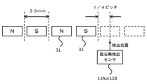
図4は、磁石無検出センサによる不規則区間の検出位置を示す図である。図4に示すように、本実施形態では、1つの磁石3(N極の磁石31及びS極の磁石32)における搬送台車1の移動方向のピッチは33mmとされている。磁石無検出センサ11A,11Bは、少なくとも、磁石3の検出位置が磁石3の無くなった位置から磁石3の1/4ピッチになるまでに、磁石3が配置されていないこと、すなわち不規則区間に入ったことを検出する。なぜなら、N極の磁石31とS極の磁石32との組み合わせのピッチ(2つ分の磁石3のピッチ)で360°(2π)の磁極の位相をとした場合に、磁極の位相とモータ10A,10Bの電気角の位相とが90°(π/2)ずれてしまうと、水平方向の推力がcos90°となるとともに、垂直方向への力がsin90°となる。すなわち、推力がなくなるとともに、垂直方向への力が大きく働いてしまう。この場合、垂直方向への力が働くことにより、モータ10A,10Bと磁石3が吸着したり、搬送台車1が飛び上がったりすることが起こり得る。また、このような状況が繰り返されると、磁石3自体が減磁することも起こり得る。このような事態を避けるために、モータ10A,10Bが不規則区間に位置しているときは、モータ10A,10Bの駆動を停止させる。   FIG. 4 is a diagram illustrating a detection position of an irregular section by a magnet non-detection sensor. As shown in FIG. 4, in this embodiment, the pitch in the moving direction of the transport carriage 1 in one magnet 3 (N pole magnet 31 and S pole magnet 32) is set to 33 mm. The non-magnet detection sensors 11A and 11B are configured such that the magnet 3 is not disposed at least until the detection position of the magnet 3 becomes 1/4 pitch of the magnet 3 from the position where the magnet 3 is lost, that is, in an irregular section. Detects entry. This is because when the phase of the magnetic pole is 360 ° (2π) at the pitch of the combination of the N-pole magnet 31 and the S-pole magnet 32 (the pitch of the two magnets 3), the phase of the magnetic pole and the motor 10A , 10B shifts by 90 ° (π / 2) from the electrical angle phase, the horizontal thrust becomes cos 90 ° and the vertical force becomes sin 90 °. That is, the thrust is lost and the force in the vertical direction is greatly increased. In this case, when the force in the vertical direction works, the motors 10A and 10B and the magnet 3 may be attracted or the transport carriage 1 may jump up. Further, when such a situation is repeated, the magnet 3 itself may be demagnetized. In order to avoid such a situation, when the motors 10A and 10B are located in irregular sections, the driving of the motors 10A and 10B is stopped.

ここで、磁石無検出センサ11A,11Bは、モータ10A,10Bが不規則区間に位置しているか否かを判定しているので、磁石無検出センサ11A,11Bの位置とモータ10A,10Bの位置とが一致または近い位置にあることが好ましい。しかし、磁石無検出センサ11A,11Bの位置とモータ10A,10Bの位置との距離が予めわかっている場合は、その距離に基づいて、磁石無検出センサ11A,11Bが不規則区間に入った時点からモータ10A,10Bが不規則区間に入った時点までの時間を、搬送台車1の現在の速度を参照して予測することが可能である。   Here, since the magnet non-detection sensors 11A and 11B determine whether or not the motors 10A and 10B are positioned in irregular sections, the positions of the magnet non-detection sensors 11A and 11B and the positions of the motors 10A and 10B are determined. Is preferably at or near the same position. However, when the distance between the positions of the non-magnet detection sensors 11A and 11B and the positions of the motors 10A and 10B is known in advance, the time when the non-magnet detection sensors 11A and 11B enter an irregular section based on the distance. It is possible to predict the time from when the motor 10A, 10B enters the irregular section to the current speed of the transport carriage 1.

次に、移動体システムの動作について説明する。   Next, the operation of the mobile system will be described.

(1)磁石無検出センサ11A,11Bの検出信号に基づくモータ駆動制御:
図5は、制御部による駆動指令処理を示すフローチャートである。また、図6は、磁石無しの検出とモータの駆動との関係を示すタイミングチャートである。なお、図6において、(F)はフロント(前方)を意味し、(R)はリア(後方)を意味する。
(1) Motor drive control based on detection signals from the non-magnet detection sensors 11A and 11B:
FIG. 5 is a flowchart showing drive command processing by the control unit. FIG. 6 is a timing chart showing the relationship between detection of no magnet and driving of the motor. In FIG. 6, (F) means front (front), and (R) means rear (rear).

図5に示すように、制御部13は、第1磁石無検出センサ11Aからの検出信号を常時確認している(ステップS1)。そして、制御部13は、第1磁石無検出センサ11Aが磁石無しを検出していない場合は(ステップS1のNO)、第1モータ10Aを継続して駆動させる(ステップS2)。すなわち、制御部13は、第1駆動制御部14Aに第1モータ10Aの駆動を指示する駆動オン指令を継続して出力する。   As shown in FIG. 5, the control unit 13 constantly confirms the detection signal from the first magnet non-detection sensor 11A (step S1). Then, when the first magnet non-detection sensor 11A does not detect the absence of a magnet (NO in step S1), the control unit 13 continuously drives the first motor 10A (step S2). That is, the control unit 13 continuously outputs a drive-on command that instructs the first drive control unit 14A to drive the first motor 10A.

一方、制御部13は、第1磁石無検出センサ11Aが磁石無しを検出した場合は(ステップS1のYES)、第1モータ10Aを駆動を停止させる(ステップS3)。すなわち、制御部13は、第1駆動制御部14Aに第1モータ10Aの駆動の停止を指示する駆動オン指令を出力する。   On the other hand, when the first magnet non-detection sensor 11A detects the absence of a magnet (YES in step S1), the control unit 13 stops driving the first motor 10A (step S3). That is, the control unit 13 outputs a drive-on command that instructs the first drive control unit 14A to stop driving the first motor 10A.

具体的には、ステップS1〜S3として以下のような処理が行われる。制御部13は、図6の時間t1までは、第1磁石無検出センサ11Aからの検出信号がロウレベルであるので、第1磁石無検出センサ11Aが磁石無しを検出していないと判定する。このとき、制御部13は、第1駆動制御部14Aに対して第1モータ10Aの駆動を指示する駆動オン指令を出力する。図6に示すように、駆動の停止を指示する駆動オン指令は、ハイレベルの信号である。図6の時間t1になったときに、第1磁石無検出センサ11Aからの検出信号がロウレベルからハイレベルに変化する。これにより、制御部13は、第1磁石無検出センサ11Aが磁石無しを検出したと判定する。そして、制御部13は、第1駆動制御部14Aに対して第1モータ10Aの駆動の停止を指示する駆動オン指令を出力する。図6に示すように、駆動を指示する駆動オン指令は、ロウレベルの信号である。図6の時間t1からt2までの時間は、制御部13が検出信号がハイレベルに変化したと判断してから駆動オン指令をロウレベルに変化させるまでのタイムラグの時間である。または、第1磁石無検出センサ11Aと第1モータ10Aとの間に距離がある場合において、第1磁石無検出センサ11Aが不規則区間に入った時点から第1モータ10Aが不規則区間に入った時点までの時間である。
Specifically, the following processing is performed as steps S1 to S3. The control unit 13 determines that the first magnet non-detection sensor 11A has not detected the absence of a magnet because the detection signal from the first magnet non-detection sensor 11A is at a low level until time t1 in FIG. At this time, the control unit 13 outputs a drive-on command that instructs the first drive control unit 14A to drive the first motor 10A. As shown in FIG. 6, the drive-on command for instructing the stop of the drive is a high level signal. When time t1 in FIG. 6 is reached, the detection signal from the first magnet non-detection sensor 11A changes from the low level to the high level. Thereby, the control unit 13 determines that the first magnet non-detection sensor 11A has detected the absence of a magnet. The control unit 13 then outputs a drive-on command that instructs the first drive control unit 14A to stop driving the first motor 10A. As shown in FIG. 6, the drive-on command for instructing driving is a low level signal. The time from time t1 to time t2 in FIG. 6 is a time lag time from when the control unit 13 determines that the detection signal has changed to high level to when the drive-on command is changed to low level. Alternatively, when there is a distance between the first magnet non-detection sensor 11A and the first motor 10A, the first motor 10A enters the irregular section from the time when the first magnet non-detection sensor 11A enters the irregular section. It is the time to the point.

第1駆動制御部14Aは、制御部13からの駆動オン指令に基づいて、第1モータ10Aを駆動している状態から停止した状態に制御する。図6に示すように、第1モータ10Aの駆動のオン状態はハイレベルであり、駆動のオフ状態はロウレベルである。図6の時間t2からt3までの時間は、第1駆動制御部14Aが駆動オン指令がロウレベルに変化したと判断してから第1モータ10Aを実際に停止させるまでのタイムラグの時間である。   Based on the drive-on command from the control unit 13, the first drive control unit 14A controls the first motor 10A from being driven to being stopped. As shown in FIG. 6, the driving ON state of the first motor 10A is at a high level, and the driving OFF state is at a low level. The time from time t2 to time t3 in FIG. 6 is a time lag time from when the first drive control unit 14A determines that the drive-on command has changed to a low level until the first motor 10A is actually stopped.

図6の時間t4になったときに、第1磁石無検出センサ11Aからの検出信号がハイレベルからロウレベルに変化する。これにより、制御部13は、第1磁石無検出センサ11Aが磁石無しを検出していないと判定する。そして、制御部13は、第1駆動制御部14Aに対して第1モータ10Aの駆動を指示する駆動オン指令を出力する。図6の時間t4からt5までの時間は、制御部13が検出信号がロウレベルに変化したと判断してから駆動オン指令をハイレベルに変化させるまでのタイムラグの時間である。または、第1磁石無検出センサ11Aと第1モータ10Aとの間に距離がある場合において、磁石無検出センサ11A,11Bが不規則区間から出た時点からモータ10A,10Bが不規則区間から出た時点までの時間である。   At time t4 in FIG. 6, the detection signal from the first magnet non-detection sensor 11A changes from the high level to the low level. Thereby, the control part 13 determines with 11 A of 1st magnet non-detection sensors not detecting the absence of a magnet. Then, the control unit 13 outputs a drive-on command that instructs the first drive control unit 14A to drive the first motor 10A. The time from time t4 to time t5 in FIG. 6 is a time lag time from when the control unit 13 determines that the detection signal has changed to low level to when the drive-on command is changed to high level. Alternatively, when there is a distance between the first magnet non-detection sensor 11A and the first motor 10A, the motors 10A and 10B exit from the irregular section from the time when the magnet non-detection sensors 11A and 11B exit from the irregular section. It is the time to the point.

第1駆動制御部14Aは、制御部13からの駆動オン指令に基づいて、第1モータ10Aの駆動を停止している状態から駆動した状態に制御する。図6の時間t5からt6までの時間は、第1駆動制御部14Aが駆動オン指令がハイレベルに変化したと判断してから第1モータ10Aを実際に駆動させるまでのタイムラグの時間である。   Based on the drive-on command from the control unit 13, the first drive control unit 14A controls the first motor 10A from being stopped to being driven. The time from time t5 to time t6 in FIG. 6 is a time lag time from when the first drive control unit 14A determines that the drive-on command has changed to a high level until the first motor 10A is actually driven.

図5の説明に戻り、制御部13は、第2磁石無検出センサ11Bからの検出信号を常時確認している(ステップS4)。そして、制御部13は、第2磁石無検出センサ11Bが磁石無しを検出していない場合は(ステップS4のNO)、第2モータ10Bを継続して駆動させる(ステップS5)。すなわち、制御部13は、第2駆動制御部14Bに第2モータ10Bの駆動を指示する駆動オン指令を継続して出力する。   Returning to the description of FIG. 5, the control unit 13 constantly confirms the detection signal from the second magnet non-detection sensor 11B (step S4). And the control part 13 drives the 2nd motor 10B continuously, when the 2nd magnet non-detection sensor 11B has not detected the absence of a magnet (NO of step S4) (step S5). That is, the control unit 13 continuously outputs a drive-on command that instructs the second drive control unit 14B to drive the second motor 10B.

一方、制御部13は、第2磁石無検出センサ11Bが磁石無しを検出した場合は(ステップS4のYES)、第2モータ10Bを駆動を停止させる(ステップS5)。すなわち、制御部13は、第2駆動制御部14Bに第2モータ10Bの駆動の停止を指示する駆動オン指令を出力する。   On the other hand, when the second magnet non-detection sensor 11B detects the absence of a magnet (YES in step S4), the control unit 13 stops driving the second motor 10B (step S5). That is, the control unit 13 outputs a drive-on command that instructs the second drive control unit 14B to stop driving the second motor 10B.

具体的には、ステップS4〜S6として以下のような処理が行われる。制御部13は、図6の時間t7までは、第2磁石無検出センサ11Bからの検出信号がロウレベルであるので、第2磁石無検出センサ11Bが磁石無しを検出していないと判定する。このとき、制御部13は、第2駆動制御部14Bに対して第2モータ10Bの駆動を指示する駆動オン指令を出力する。図6の時間t7になったときに、第2磁石無検出センサ11Bからの検出信号がロウレベルからハイレベルに変化する。これにより、制御部13は、第2磁石無検出センサ11Bが磁石無しを検出したと判定する。そして、制御部13は、第2駆動制御部14Bに対して第2モータ10Bの駆動の停止を指示する駆動オン指令を出力する。図6の時間t7からt8までの時間は、制御部13が検出信号がハイレベルに変化したと判断してから駆動オン指令をロウレベルに変化させるまでのタイムラグの時間である。または、第2磁石無検出センサ11Bと第2モータ10Bとの間に距離がある場合において、第2磁石無検出センサ11Bが不規則区間に入った時点から第2モータ10Bが不規則区間に入った時点までの時間である。   Specifically, the following processing is performed as steps S4 to S6. The control unit 13 determines that the second magnet non-detection sensor 11B has not detected the absence of a magnet because the detection signal from the second magnet non-detection sensor 11B is at a low level until time t7 in FIG. At this time, the control unit 13 outputs a drive-on command that instructs the second drive control unit 14B to drive the second motor 10B. At time t7 in FIG. 6, the detection signal from the second magnet non-detection sensor 11B changes from the low level to the high level. Thereby, the control part 13 determines with the 2nd magnet non-detection sensor 11B having detected the absence of a magnet. Then, the control unit 13 outputs a drive-on command that instructs the second drive control unit 14B to stop driving the second motor 10B. The time from time t7 to time t8 in FIG. 6 is a time lag time from when the control unit 13 determines that the detection signal has changed to high level to when the drive-on command is changed to low level. Alternatively, when there is a distance between the second magnet non-detection sensor 11B and the second motor 10B, the second motor 10B enters the irregular section from the time when the second magnet non-detection sensor 11B enters the irregular section. It is the time to the point.

第2駆動制御部14Bは、制御部13からの駆動オン指令に基づいて、第2モータ10Bを駆動している状態から停止した状態に制御する。図6に示すように、第2モータ10Bの駆動のオン状態はハイレベルであり、駆動のオフ状態はロウレベルである。図6の時間t8からt9までの時間は、第2駆動制御部14Bが駆動オン指令がロウレベルに変化したと判断してから第2モータ10Bを実際に停止させるまでのタイムラグの時間である。   Based on the drive-on command from the control unit 13, the second drive control unit 14B controls the second motor 10B from being driven to being stopped. As shown in FIG. 6, the driving ON state of the second motor 10B is at a high level, and the driving OFF state is at a low level. The time from time t8 to time t9 in FIG. 6 is a time lag time from when the second drive control unit 14B determines that the drive-on command has changed to a low level until the second motor 10B is actually stopped.

図6の時間t10になったときに、第2磁石無検出センサ11Bからの検出信号がハイレベルからロウレベルに変化する。これにより、制御部13は、第2磁石無検出センサ11Bが磁石無しを検出していないと判定する。そして、制御部13は、第2駆動制御部14Bに対して第2モータ10Bの駆動を指示する駆動オン指令を出力する。図6の時間t10からt11までの時間は、制御部13が検出信号がロウレベルに変化したと判断してから駆動オン指令をハイレベルに変化させるまでのタイムラグの時間である。または、第2磁石無検出センサ11Bと第2モータ10Bとの間に距離がある場合において、第2磁石無検出センサ11Bが不規則区間から出た時点から第2モータ10Bが不規則区間から出た時点までの時間である。   At time t10 in FIG. 6, the detection signal from the second magnet non-detection sensor 11B changes from the high level to the low level. Thereby, the control part 13 determines with the 2nd magnet non-detection sensor 11B not detecting the absence of a magnet. And the control part 13 outputs the drive ON command which instruct | indicates the drive of the 2nd motor 10B with respect to the 2nd drive control part 14B. The time from time t10 to time t11 in FIG. 6 is a time lag time from when the control unit 13 determines that the detection signal has changed to low level to when the drive-on command is changed to high level. Alternatively, when there is a distance between the second magnet non-detection sensor 11B and the second motor 10B, the second motor 10B exits from the irregular section from the time when the second magnet non-detection sensor 11B exits from the irregular section. It is the time to the point.

第2駆動制御部14Bは、制御部13からの駆動オン指令に基づいて、第2モータ10Bの駆動を停止している状態から駆動した状態に制御する。図6の時間t11からt12までの時間は、第2駆動制御部14Bが駆動オン指令がハイレベルに変化したと判断してから第2モータ10Bを実際に駆動させるまでのタイムラグの時間である。   Based on the drive-on command from the control unit 13, the second drive control unit 14B controls the second motor 10B from being stopped to being driven. The time from time t11 to time t12 in FIG. 6 is a time lag time from when the second drive control unit 14B determines that the drive-on command has changed to a high level until the second motor 10B is actually driven.

本実施形態では、第1モータ10A又は第2モータ10Bが不規則区間に位置しているときに、制御部13が第1モータ10A又は第2モータ10Bの駆動を停止させている。従って、第1モータ10A又は第2モータ10Bが不規則区間に位置しているときにおいて、第1モータ10A又は第2モータ10Bと磁石3との同期がとれなくなることが防止される。   In the present embodiment, when the first motor 10A or the second motor 10B is located in an irregular section, the control unit 13 stops driving the first motor 10A or the second motor 10B. Therefore, when the first motor 10A or the second motor 10B is located in an irregular section, the first motor 10A or the second motor 10B and the magnet 3 are prevented from being out of synchronization.

また、第1モータ10A又は第2モータ10Bが不規則区間から規則区間(N極の磁石31とS極の磁石32が交互に規則的に配置されている区間)に移動したときに、制御部13が第1モータ10A又は第2モータ10Bの駆動を開始させる。すなわち、第1モータ10A又は第2モータ10Bが規則区間に移動した時点(不規則区間が終了した時点)で、制御部13が駆動制御部14に駆動オン指令を出力するとともに、新たに位置指令を駆動制御部14に出力する。これにより、駆動制御部14が磁石3の位置と同期させて第1モータ10A又は第2モータ10Bの駆動制御を実行する。従って、第1モータ10A又は第2モータ10Bが不規則区間を通過した後に、第1モータ10A又は第2モータ10Bの電気角と磁石3の磁極とが同期しなくなることが防止される。   When the first motor 10A or the second motor 10B moves from an irregular section to a regular section (a section in which N pole magnets 31 and S pole magnets 32 are alternately arranged regularly), the control unit 13 starts driving the first motor 10A or the second motor 10B. That is, when the first motor 10A or the second motor 10B moves to the regular section (when the irregular section ends), the control unit 13 outputs a drive-on command to the drive control unit 14 and newly adds a position command. Is output to the drive control unit 14. Thereby, the drive control part 14 synchronizes with the position of the magnet 3, and performs drive control of the 1st motor 10A or the 2nd motor 10B. Therefore, after the first motor 10A or the second motor 10B passes through the irregular section, the electrical angle of the first motor 10A or the second motor 10B and the magnetic pole of the magnet 3 are prevented from becoming out of synchronization.

なお、不規則区間が終了した後の規則区間における最初の磁石3の位置から第1モータ10A又は第2モータ10Bの駆動が開始されるのではなく、規則区間における最初の磁石3から数個の磁石3の位置から第1モータ10A又は第2モータ10Bの駆動が開始されるようにしてもよい。具体的には、第1磁石無検出センサ11A又は第2磁石無検出センサ11Bが規則区間における数個の磁石3を連続して検出した時点で、制御部13は、駆動制御部14に駆動オン指令を出力するとともに、新たに位置指令を駆動制御部14に出力するようにしてもよい。このような構成によれば、規則区間の開始時に確実に第1モータ10A又は第2モータ10Bの電気角と磁石3の位置とを同期させることができる。   Note that the driving of the first motor 10A or the second motor 10B is not started from the position of the first magnet 3 in the regular section after the irregular section is finished, but several first magnets 3 in the regular section are started. The driving of the first motor 10A or the second motor 10B may be started from the position of the magnet 3. Specifically, when the first magnet non-detection sensor 11A or the second magnet non-detection sensor 11B continuously detects several magnets 3 in the regular section, the control unit 13 turns on the drive control unit 14 to drive on. A command may be output and a new position command may be output to the drive control unit 14. According to such a configuration, the electrical angle of the first motor 10A or the second motor 10B and the position of the magnet 3 can be reliably synchronized at the start of the regular section.

(2)ブートストラップ回路の動作:
次に、駆動制御部14A,14Bのインバータ145A,145Bに実装されているブートストラップ回路の構成について説明する。図7は、インバータに実装されるブートストラップ回路の構成を示す回路図である。インバータ145A,145Bは、ブートストラップ回路50を実装することにより、通常の回路構成ではIGBT(Insulated Gate Bipolar Transistor)の駆動用にそれぞれ必要な電源を、一方側の電源1つで動作させることができる。モータの始動時に、一方側のIGBTをターンオンさせることによって、コンデンサ(ブートストラップコンデンサ)に電荷をチャージする。そして、駆動中はコンデンサを反対側の駆動用の電源として使用する。
(2) Bootstrap circuit operation:
Next, the configuration of the bootstrap circuit mounted on the inverters 145A and 145B of the drive control units 14A and 14B will be described. FIG. 7 is a circuit diagram showing a configuration of a bootstrap circuit mounted on the inverter. Inverters 145A and 145B can be operated with a single power supply on one side for mounting a bootstrap circuit 50 to drive an IGBT (Insulated Gate Bipolar Transistor) in a normal circuit configuration. . When starting the motor, the IGBT on one side is turned on to charge the capacitor (bootstrap capacitor). During driving, the capacitor is used as a driving power source on the opposite side.

ところで、一方側のIGBTがターンオフされることによりコンデンサが放電される。このため、始動時において、駆動中に必要な電荷をコンデンサへチャージするのに十分なチャージ時間を確保する必要がある。そして、インバータ145A,145Bの出力を完全に停止するために、IGBTの全てをターンオフする場合に、停止状態から高速な始動が不可能となる。特に、本実施形態では、モータ10A,10Bが不規則区間に位置しているときに、モータ10A,10Bの駆動を停止させるためにインバータ145A,145Bの出力を停止させ、その後、モータ10A,10Bが不規則区間に位置しなくなったときに、モータ10A,10Bを駆動させるためにインバータ145A,145Bの出力を開始させる(図6参照)。従って、本実施形態では、停止状態から高速な始動が必要となる。   By the way, the capacitor is discharged by turning off the IGBT on one side. For this reason, at the time of start-up, it is necessary to secure a sufficient charge time for charging the capacitor with the necessary charge during driving. In order to completely stop the outputs of the inverters 145A and 145B, when all of the IGBTs are turned off, it is impossible to start at high speed from the stopped state. In particular, in the present embodiment, when the motors 10A and 10B are located in irregular sections, the outputs of the inverters 145A and 145B are stopped in order to stop the driving of the motors 10A and 10B, and then the motors 10A and 10B are stopped. Is no longer in the irregular section, the outputs of the inverters 145A and 145B are started to drive the motors 10A and 10B (see FIG. 6). Therefore, in the present embodiment, high-speed starting from the stopped state is necessary.

インバータに実装されるブートストラップ回路50の回路構成について説明する。ブートストラップ回路50は、ブートストラップコンデンサ60と、ブートストラップダイオード(高耐圧高速ダイオード)61と、電流制限抵抗62とで構成されている。図7において、P−sideIGBT54(以下、IGBT54又はP側IGBT54という)のコレクタ端子と電圧Vccを入力するP端子51とが接続されるとともに、IGBT54のエミッタ端子と各相の出力端子53(例えばU端子など)とが接続されている。また、IGBT54のゲート端子にHVIC(High Voltage IC)56が接続されている。また、IGBT54のコレクタ端子とエミッタ端子との間に、負荷電流を転流させるためのダイオード55が接続されている。HVIC56は、マイクロコンピュータ(本実施形態では駆動制御部14A,14Bのマイクロコンピュータ)などの入力信号により、直接、高電圧側のIGBT54のゲートを駆動するIC回路である。   A circuit configuration of the bootstrap circuit 50 mounted on the inverter will be described. The bootstrap circuit 50 includes a bootstrap capacitor 60, a bootstrap diode (high voltage fast diode) 61, and a current limiting resistor 62. In FIG. 7, a collector terminal of a P-side IGBT 54 (hereinafter referred to as IGBT 54 or P-side IGBT 54) and a P terminal 51 for inputting a voltage Vcc are connected, and an emitter terminal of the IGBT 54 and an output terminal 53 for each phase (for example, U Terminal). An HVIC (High Voltage IC) 56 is connected to the gate terminal of the IGBT 54. Further, a diode 55 for commutating a load current is connected between the collector terminal and the emitter terminal of the IGBT 54. The HVIC 56 is an IC circuit that directly drives the gate of the IGBT 54 on the high voltage side by an input signal of a microcomputer (in this embodiment, the microcomputers of the drive control units 14A and 14B).

また、N−sideIGBT57(以下、IGBT57又はN側IGBT57という)のコレクタ端子と各相の出力端子53とが接続されるとともに、IGBT57のエミッタ端子と電位がグランドレベルのN端子52とが接続されている。また、IGBT57のゲート端子にLVIC(Low Voltage IC)59が接続されている。また、IGBT57のコレクタ端子とエミッタ端子との間に、負荷電流を転流させるためのダイオード58が接続されている。LVIC59は、マイクロコンピュータ(本実施形態では駆動制御部14A,14Bのマイクロコンピュータ)などの入力信号により、直接、低電圧側のIGBT57のゲートを駆動するIC回路である。   Further, the collector terminal of the N-side IGBT 57 (hereinafter referred to as IGBT 57 or N-side IGBT 57) and the output terminal 53 of each phase are connected, and the emitter terminal of the IGBT 57 and the N terminal 52 whose potential is ground level are connected. Yes. An LVIC (Low Voltage IC) 59 is connected to the gate terminal of the IGBT 57. A diode 58 for commutating the load current is connected between the collector terminal and the emitter terminal of the IGBT 57. The LVIC 59 is an IC circuit that directly drives the gate of the IGBT 57 on the low voltage side by an input signal of a microcomputer (in this embodiment, the microcomputers of the drive control units 14A and 14B).

ブートストラップコンデンサ60は、HVIC56の入力側の接続点と各相の出力端子53との間に接続されている。また、HVIC56の入力側の接続点とLVIC59の入力側の接続点との間に、ブートストラップダイオード61と電流制限抵抗62とが直列に接続されている。また、電源VD63はIGBT57の駆動用の電源である。この電源VD63は、IGBT57のコレクタ端子とエミッタ端子との間に接続されている。   The bootstrap capacitor 60 is connected between the connection point on the input side of the HVIC 56 and the output terminal 53 of each phase. Further, a bootstrap diode 61 and a current limiting resistor 62 are connected in series between a connection point on the input side of the HVIC 56 and a connection point on the input side of the LVIC 59. The power source VD63 is a power source for driving the IGBT 57. The power source VD63 is connected between the collector terminal and the emitter terminal of the IGBT 57.

インバータ145A,145Bの駆動中は、HVIC56がIGBT55をターンオンさせるとともに、LVIC59がIGBT57をターンオフさせることにより、各相の出力端子53の電位がVccレベルの電位となる。また、HVIC56がIGBT55をターンオフさせるとともに、LVIC59がIGBT57をターンオンさせることにより、各相の出力端子53の電位がグランドレベルの電位となる。このような動作を繰り返し実行することにより、PWM(Pulse Width Modulation)制御が行われる。   While the inverters 145A and 145B are being driven, the HVIC 56 turns on the IGBT 55 and the LVIC 59 turns off the IGBT 57, whereby the potential of the output terminal 53 of each phase becomes the potential of the Vcc level. Further, the HVIC 56 turns off the IGBT 55 and the LVIC 59 turns on the IGBT 57, whereby the potential of the output terminal 53 of each phase becomes the ground level potential. By repeating such operations, PWM (Pulse Width Modulation) control is performed.

図8は、ブートストラップ回路における初期充電時の各電圧の関係を示すタイミングチャートである。始動時T1において、まず、電圧Vccが徐々に上昇するとともに、電圧VDが上昇する。電圧Vccが所定電圧になった時点T2で、マイクロコンピュータからLVIC59に対してパルス電圧VIN(N)が入力される。LVIC59に対してパルス電圧VIN(N)が入力されると、LVIC59がIGBT57を駆動し、IGBT57がターンオンする。IGBT57がターンオンすると、図7に示すようなループで電流が流れ、ブートストラップコンデンサ60に電荷がチャージされていく。ブートストラップコンデンサ60に電荷がチャージされていくとともに、ブートストラップコンデンサ60の充電電圧VDBが徐々に上昇していく。そして、T3の時点でIGBT54がHVIC56の駆動によってターンオンすると、ブートストラップコンデンサ60の電荷量がUGBT54の駆動用に用いられて、充電電圧VDBが徐々に低下していく。   FIG. 8 is a timing chart showing the relationship between voltages at the time of initial charging in the bootstrap circuit. At start-up time T1, first, the voltage Vcc gradually rises and the voltage VD rises. At the time T2 when the voltage Vcc becomes a predetermined voltage, the pulse voltage VIN (N) is input from the microcomputer to the LVIC 59. When the pulse voltage VIN (N) is input to the LVIC 59, the LVIC 59 drives the IGBT 57, and the IGBT 57 is turned on. When the IGBT 57 is turned on, a current flows in a loop as shown in FIG. 7 and the bootstrap capacitor 60 is charged. As the bootstrap capacitor 60 is charged, the charging voltage VDB of the bootstrap capacitor 60 gradually increases. When the IGBT 54 is turned on by driving the HVIC 56 at time T3, the charge amount of the bootstrap capacitor 60 is used for driving the UGBT 54, and the charging voltage VDB gradually decreases.

図9は、ブートストラップコンデンサの電圧の波形を示す波形図である。図9に示すように、モータの駆動オンの状態のとき(インバータ145A,145Bの駆動中)は、充電と放電が繰り返されるため、ブートストラップコンデンサ60の充電電圧VDBは上昇と下降を繰り返す。このとき、IGBT54の駆動用の電源として機能するためには充電電圧VDBは電圧Vmin以上必要とされている。   FIG. 9 is a waveform diagram showing a voltage waveform of the bootstrap capacitor. As shown in FIG. 9, when the drive of the motor is on (while the inverters 145A and 145B are being driven), charging and discharging are repeated, so that the charging voltage VDB of the bootstrap capacitor 60 repeatedly rises and falls. At this time, in order to function as a power source for driving the IGBT 54, the charging voltage VDB is required to be equal to or higher than the voltage Vmin.

モータの駆動オフの状態(インバータ145A,145Bの駆動が停止した状態)になると、ブートストラップコンデンサ60の充電電圧VDBは徐々に低下していく。その後、モータの駆動オンの状態になる前に、IGBT57がターンオンすることにより、ブートストラップコンデンサ60の充電電圧VDBが徐々に上昇していく。そして、充電電圧VDBが電圧値Vminになった時点からインバータ145A,145Bの駆動が開始され、モータの駆動オンの状態となる。   When the motor drive is turned off (the drive of the inverters 145A and 145B is stopped), the charging voltage VDB of the bootstrap capacitor 60 gradually decreases. Thereafter, before the motor is turned on, the IGBT 57 is turned on, so that the charging voltage VDB of the bootstrap capacitor 60 gradually increases. Then, the driving of the inverters 145A and 145B is started from the time when the charging voltage VDB reaches the voltage value Vmin, and the motor is turned on.

図9に示すように、モータの駆動オンの状態から駆動オフの状態に移行する場合、モータの駆動がオフとなった時点(具体的にはIGBT57がターンオフした時点)から時間τ1(モータの駆動がオフとなっていた時間)経過後の充電電圧の電圧値V1は、コンデンサの放電特性によって、V1=F(τ1,V0)となる。   As shown in FIG. 9, when shifting from the motor drive-on state to the drive-off state, time τ1 (motor drive) from when the motor drive is turned off (specifically, when the IGBT 57 is turned off). The voltage value V1 of the charging voltage after the elapse of time is V1 = F (τ1, V0) due to the discharge characteristics of the capacitor.

また、チャージポンプが再開されてから時間τ2経過後の充電電圧VDBの電圧値V2は、コンデンサのチャージポンプ特性によって、V2=G(τ2,V1)となる。この式をτ2に対して解くことにより、τ2=g(V1,V2)となる。そして、P側IGBT54の駆動に必要な電圧をVminとすると、τ2=g(F(τ1,V0),Vmin)と算出される。通常、電圧値V0は、駆動中の最低値として設計されており、電圧値Vminとともに固定値として、τ2=f(τ1)の式で算出される。   Further, the voltage value V2 of the charging voltage VDB after the elapse of time τ2 after the restart of the charge pump is V2 = G (τ2, V1) due to the charge pump characteristics of the capacitor. By solving this equation for τ2, τ2 = g (V1, V2). When the voltage necessary for driving the P-side IGBT 54 is Vmin, τ2 = g (F (τ1, V0), Vmin) is calculated. Normally, the voltage value V0 is designed as the lowest value during driving, and is calculated as a fixed value together with the voltage value Vmin by the equation τ2 = f (τ1).

このようなことから、チャージポンプの再開後における充電電圧VDBの電圧値V2が電圧値Vmin以上になった時点で、モータの駆動オンの状態とすることができる。従って、駆動オフした時間τ1(ブートストラップコンデンサ60の放電時間)に応じて充電時間τ2を決定することにより、最短時間で確実にIGBT54をターンオンさせることができる。   For this reason, when the voltage value V2 of the charging voltage VDB becomes equal to or higher than the voltage value Vmin after restarting the charge pump, the motor can be turned on. Therefore, the IGBT 54 can be reliably turned on in the shortest time by determining the charging time τ2 according to the driving time τ1 (the discharging time of the bootstrap capacitor 60).

このような構成を実現するために、駆動制御部14のマイクロコンピュータなどにおいて、P側IGBT57がターンオフした時点からチャージポンプが開始されるまでの時間を計測し、計測した時間に応じた充電時間を算出する。そして、マイクロコンピュータなどにおいて、算出した充電時間でブートストラップコンデンサ60を充電する。   In order to realize such a configuration, in the microcomputer of the drive control unit 14 or the like, the time from when the P-side IGBT 57 is turned off until the charge pump is started is measured, and the charging time corresponding to the measured time is determined. calculate. Then, in the microcomputer or the like, the bootstrap capacitor 60 is charged with the calculated charging time.

(3)位置検出センサ12A,12Bの検出信号に基づく位置制御:
図10は、制御部による位置指令処理を示すフローチャートである。図10に示すように、制御部13は、上述したように、常時、第1位置検出センサ12A及び第2位置検出センサ12Bからの検出信号を監視している。そして、制御部13は、第1位置検出センサ12Aからの検出信号に基づいて搬送台車1の現在位置を特定する(ステップS11)。
(3) Position control based on detection signals of the position detection sensors 12A and 12B:
FIG. 10 is a flowchart showing position command processing by the control unit. As shown in FIG. 10, the control unit 13 constantly monitors the detection signals from the first position detection sensor 12A and the second position detection sensor 12B as described above. And the control part 13 pinpoints the present position of the conveyance trolley | bogie 1 based on the detection signal from 12 A of 1st position detection sensors (step S11).

また、制御部13は、第1位置検出センサ12Aからの検出信号に基づいて、この第1位置検出センサ12Aが不規則区間に位置しているか否かを判定する(ステップS12)。第1位置検出センサ12Aが不規則区間に位置していないと判定した場合は(ステップS12のNO)、制御部13は、ステップS11で特定した搬送台車1の現在位置に基づいて、搬送台車1の移動位置を指示する位置指令を駆動制御部14に出力する(ステップS15)。このとき、制御部13のモーション・コントローラ133は、第1モータ10Aが不規則区間に位置していないことを示す磁石無検出状態信号をポジションコントローラ131から入力していることを条件に、第1駆動制御部14Aに位置指令を出力する。同様に、モーション・コントローラ133は、第2モータ10Bが不規則区間に位置していないことを示す磁石無検出状態信号をポジションコントローラ131から入力していることを条件に、第2駆動制御部14Bに位置指令を出力する。   Moreover, the control part 13 determines whether this 1st position detection sensor 12A is located in an irregular area based on the detection signal from 12 A of 1st position detection sensors (step S12). When it is determined that the first position detection sensor 12A is not located in the irregular section (NO in step S12), the control unit 13 determines the transport cart 1 based on the current position of the transport cart 1 specified in step S11. A position command for instructing the movement position is output to the drive control unit 14 (step S15). At this time, the motion controller 133 of the control unit 13 performs the first operation on the condition that the magnet non-detection state signal indicating that the first motor 10A is not located in the irregular section is input from the position controller 131. A position command is output to the drive control unit 14A. Similarly, on the condition that the motion controller 133 inputs a magnet non-detection state signal indicating that the second motor 10B is not located in an irregular section from the position controller 131, the second drive control unit 14B Position command is output to.

一方、第1位置検出センサ12Aが不規則区間に位置していると判定した場合は(ステップS12のYES)、制御部13は、第2位置検出センサ12Bからの検出信号に基づいて、搬送台車1の不規則区間の移動距離を特定する(ステップS13)。そして、制御部13は、搬送台車1の不規則区間の移動距離から搬送台車1の現在位置を特定する(ステップS14)。その後、制御部13は、ステップS14で特定した搬送台車1の現在位置に基づいて、搬送台車1の移動位置を指示する位置指令を駆動制御部14に出力する(ステップS15)。   On the other hand, when it is determined that the first position detection sensor 12A is located in the irregular section (YES in step S12), the control unit 13 determines the conveyance carriage based on the detection signal from the second position detection sensor 12B. The moving distance of one irregular section is specified (step S13). And the control part 13 pinpoints the present position of the conveyance trolley 1 from the movement distance of the irregular area of the conveyance trolley 1 (step S14). Thereafter, the control unit 13 outputs a position command for instructing the moving position of the transport carriage 1 to the drive control unit 14 based on the current position of the transport carriage 1 specified in Step S14 (Step S15).

図11は、第1位置検出センサが不規則区間に位置しているときの第2位置検出センサによる位置検出の補完制御を説明するための図である。制御部13は、第1位置検出センサ12Aが不規則区間に位置していない場合は(ステップS12のNO)、ステップS11において第1位置検出センサ12Aからの検出信号に基づいて搬送台車1の現在位置を特定する(ステップS11)。具体的には、第1位置検出センサ12Aは、搬送台車1の移動に伴って変化する、ホール素子からの電圧値に応じた検出信号を制御部13(ここではポジションコントローラ131)に出力する。例えば、搬送台車1が一定速度で走行しているときは、同じ周期で変化する検出信号が出力される。制御部13は、第1位置検出センサ12Aからの検出信号の変化をカウント(すなわちインクリメント)することにより、搬送台車1が通過した磁石3の数を特定し、搬送台車1の位置を特定する。   FIG. 11 is a diagram for explaining complementary control of position detection by the second position detection sensor when the first position detection sensor is located in an irregular section. When the first position detection sensor 12A is not located in the irregular section (NO in step S12), the control unit 13 determines the current state of the transport carriage 1 based on the detection signal from the first position detection sensor 12A in step S11. A position is specified (step S11). Specifically, the first position detection sensor 12A outputs a detection signal corresponding to the voltage value from the hall element, which changes with the movement of the transport carriage 1, to the control unit 13 (here, the position controller 131). For example, when the transport carriage 1 is traveling at a constant speed, a detection signal that changes in the same cycle is output. The control unit 13 counts (that is, increments) the change in the detection signal from the first position detection sensor 12 </ b> A to identify the number of magnets 3 that the transport carriage 1 has passed, and thus identifies the position of the transport carriage 1.

図11において、制御部13は、N極の磁石31とS極の磁石32の1組の単位で、1のローカル位置を特定し、そのローカル位置を足し合わせる(統合する)ことによって搬送台車1の統合位置を特定する。   In FIG. 11, the control unit 13 specifies one local position in a unit of a pair of N-pole magnet 31 and S-pole magnet 32, and adds (integrates) the local positions to thereby convey the carriage 1. Identify the integration location.

ここで、第1位置検出センサ12Aが不規則区間に位置しているか否かは、以下のような処理で行われる。すなわち、制御部13は、第1位置検出センサ12Aの検出信号の変化と第2位置検出センサ12Bの検出信号の変化とを比較し、それらの検出信号の変化が一致しなくなった場合に、検出センサ12A,12Bのいずれか一方が不規則区間に位置していると判断する。そして、制御部13は、搬送台車1の進行方向から、検出センサ12A,12Bのいずれが不規則区間に位置しているかを特定する。   Here, whether or not the first position detection sensor 12A is located in the irregular section is performed by the following process. That is, the control unit 13 compares the change in the detection signal of the first position detection sensor 12A with the change in the detection signal of the second position detection sensor 12B, and detects when the change in the detection signals does not match. It is determined that one of the sensors 12A and 12B is located in the irregular section. And the control part 13 pinpoints which of detection sensor 12A, 12B is located in an irregular area from the advancing direction of the conveyance trolley | bogie 1. FIG.

図11に示すように、第1位置検出センサ12Aが不規則区間に位置している場合は(ステップS12のYES)、制御部13は、搬送台車1の位置特定に用いる位置検出センサを、第1位置検出センサ12Aから第2位置検出センサ12Bに切り替える。このとき、第1位置検出センサ12Aは不規則区間に位置しているが、第2位置検出センサ12Bは不規則区間に位置していない。従って、第2位置検出センサ12Bを用いて搬送台車1の移動距離を特定することが可能となる。   As shown in FIG. 11, when the first position detection sensor 12 </ b> A is located in an irregular section (YES in step S <b> 12), the control unit 13 selects a position detection sensor used for specifying the position of the transport carriage 1. The first position detection sensor 12A is switched to the second position detection sensor 12B. At this time, the first position detection sensor 12A is located in the irregular section, but the second position detection sensor 12B is not located in the irregular section. Therefore, it is possible to specify the moving distance of the transport carriage 1 using the second position detection sensor 12B.

上述したように、制御部13は、第2位置検出センサ12Bからの検出信号に基づいて、搬送台車1の不規則区間の移動距離を特定し(ステップS13)、搬送台車1の不規則区間の移動距離から搬送台車1の現在位置を特定する(ステップS14)。すなわち、制御部13は、第位置検出センサ12からの検出信号の変化をカウント(すなわちインクリメント)することにより、搬送台車1が通過した磁石3の数を特定し、搬送台車1の移動距離を特定する。そして、制御部13は、搬送台車1の移動距離を搬送台車1の統合位置に統合することにより、搬送台車1の位置を特定する。なお、第2位置検出センサ12Bの検出信号を用いる場合に、第1位置検出センサ12Aと第2位置検出センサ12Bとの距離に基づいて搬送台車1の位置を特定するようにしてもよい。すなわち、制御部13は、第1位置検出センサ12Aのみならず、第2位置検出センサ12Bからの検出信号によっても搬送台車1の統合位置を特定する。制御部13は、第1位置検出センサ12Aが不規則区間に位置しているときに、第2位置検出センサ12Bの検出信号による搬送台車1の統合位置に、第1位置検出センサ12Aと第2位置検出センサ12Bとの距離を足し合わせる。これにより、第1位置検出センサ12Aの検出信号による搬送台車1の統合位置を特定する。
As described above, the control unit 13 specifies the movement distance of the irregular section of the transport carriage 1 based on the detection signal from the second position detection sensor 12B (step S13), and the irregular section of the transport carriage 1 is identified. The current position of the transport carriage 1 is specified from the movement distance (step S14). That is, the control unit 13, by counting the change in the detection signal from the second position detecting sensor 12 B (i.e. incrementing), to identify the number of magnet 3 the conveyance carriage 1 has passed, the moving distance of the conveyance carriage 1 Is identified. And the control part 13 pinpoints the position of the conveyance trolley 1 by integrating the moving distance of the conveyance trolley 1 in the integrated position of the conveyance trolley 1. Note that when the detection signal of the second position detection sensor 12B is used, the position of the transport carriage 1 may be specified based on the distance between the first position detection sensor 12A and the second position detection sensor 12B. That is, the control unit 13 specifies the integrated position of the transport carriage 1 not only by the first position detection sensor 12A but also by the detection signal from the second position detection sensor 12B. When the first position detection sensor 12A is located in an irregular section, the control unit 13 sets the first position detection sensor 12A and the second position at the integrated position of the transport carriage 1 based on the detection signal of the second position detection sensor 12B. The distance from the position detection sensor 12B is added. Thereby, the integrated position of the conveyance carriage 1 is specified by the detection signal of the first position detection sensor 12A.

図12は、ボギー台車を示す概略図であって、(A)は軌道が直線の場合のボギー台車の位置を示し、(B)は軌道が曲線の場合のボギー台車の位置を示している。搬送台車1における軌道2との接触部は、この搬送台車1の車体(図示せず)に対して回転可能な機構を備えたボギー台車で構成されている。なお、図12は、天井に敷設された軌道2を下から見ている場合を示している。   FIGS. 12A and 12B are schematic views showing a bogie, where FIG. 12A shows the position of the bogie when the track is a straight line, and FIG. 12B shows the position of the bogie when the track is a curve. The contact portion of the transport carriage 1 with the track 2 is constituted by a bogie truck provided with a mechanism that can rotate with respect to the vehicle body (not shown) of the transport carriage 1. FIG. 12 shows a case where the track 2 laid on the ceiling is viewed from below.

図12に示すように、搬送台車1は、2つのボギー台車100A,100Bを備えている。ボギー台車100Aは、中心ピン101Aで搬送台車1の車体に対して回転可能に連結されている。また、ボギー台車100Bは、中心ピン101Bで搬送台車1の車体に対して回転可能に連結されている。   As shown in FIG. 12, the transport cart 1 includes two bogies 100A and 100B. The bogie bogie 100A is rotatably connected to the vehicle body of the transport bogie 1 by a center pin 101A. Further, the bogie bogie 100B is rotatably connected to the vehicle body of the transport bogie 1 by a center pin 101B.

ボギー台車100Aとボギー台車100Bとの間に中間部110が配置されている。ボギー台車100Aと中間部110とが連結器111で連結されている。また、ボギー台車100Bと中間部110とが連結器112で連結されている。連結器111,112も回転可能に構成されている。また、図12に示すように、ボギー台車100Aにおける中間部110と反対側の面に第1位置検出センサ12Aが取り付けられている。また、ボギー台車100Bにおける中間部110と反対側の面に第2位置検出センサ12Bが取り付けられている。   An intermediate portion 110 is disposed between the bogie bogie 100A and the bogie bogie 100B. Bogie bogie 100 </ b> A and intermediate portion 110 are connected by a connector 111. Further, the bogie bogie 100B and the intermediate portion 110 are connected by a connector 112. The couplers 111 and 112 are also configured to be rotatable. Further, as shown in FIG. 12, the first position detection sensor 12A is attached to the surface of the bogie 100A opposite to the intermediate portion 110. Further, the second position detection sensor 12B is attached to the surface opposite to the intermediate portion 110 in the bogie 100B.

図12に示すように、ボギー台車100A,100Bにおいては、軌道2が直線の場合(図12(A))と軌道2が曲線の場合(図12(B))とで、ボギー台車100A,100Bの中心ピン101A,101B間の距離Lは変化しない。一方、軌道2が直線の場合(図12(A))と軌道2が曲線の場合(図12(B))とで、ボギー台車100Aと中間部110との距離や、ボギー台車100Bと中間部110との距離が変化する。従って、図12に示すように、軌道2が直線の場合(図12(A))と軌道2が曲線の場合(図12(B))とで、位置検出センサ12A,12B間の距離が変化する。すなわち、軌道2が直線の場合(図12(A))では、位置検出センサ12A,12B間の距離はK1である。一方、軌道2が曲線の場合(図12(B))では、位置検出センサ12A,12B間の距離はK2である。   As shown in FIG. 12, in the bogies 100A and 100B, the bogies 100A and 100B are obtained when the track 2 is a straight line (FIG. 12A) and when the track 2 is a curve (FIG. 12B). The distance L between the center pins 101A and 101B does not change. On the other hand, when the track 2 is a straight line (FIG. 12A) and when the track 2 is a curve (FIG. 12B), the distance between the bogie bogie 100A and the intermediate portion 110, or the bogie bogie 100B and the intermediate portion. The distance to 110 changes. Accordingly, as shown in FIG. 12, the distance between the position detection sensors 12A and 12B changes between when the track 2 is a straight line (FIG. 12A) and when the track 2 is a curve (FIG. 12B). To do. That is, when the track 2 is a straight line (FIG. 12A), the distance between the position detection sensors 12A and 12B is K1. On the other hand, when the track 2 is a curve (FIG. 12B), the distance between the position detection sensors 12A and 12B is K2.

このように、軌道2が直線か曲線かによって位置検出センサ12A,12B間の距離が変化する場合は、第1位置検出センサ12Aが不規則区間に位置しているときの第2位置検出センサ12Bによる位置検出の補完制御に支障を来すように思われる。しかし、本実施形態では、制御部13は、第1位置検出センサ12Aからの検出信号をインクリメントすることにより、磁石3の位置を特定し、その磁石3の位置から搬送台車1の位置を特定している。従って、位置検出センサ12A,12B間の距離が変化した場合であっても、制御部13が第1位置検出センサ12Aからの検出信号に基づきインクリメントする磁石3の数を間違わなければ、搬送台車1の統合位置が本来の位置とずれてしまうことはない。   Thus, when the distance between the position detection sensors 12A and 12B changes depending on whether the trajectory 2 is a straight line or a curve, the second position detection sensor 12B when the first position detection sensor 12A is located in an irregular section. It seems to interfere with the complementary control of position detection. However, in this embodiment, the controller 13 specifies the position of the magnet 3 by incrementing the detection signal from the first position detection sensor 12A, and specifies the position of the transport carriage 1 from the position of the magnet 3. ing. Therefore, even if the distance between the position detection sensors 12A and 12B changes, the transport carriage 1 can be used as long as the controller 13 does not make a mistake in the number of magnets 3 incremented based on the detection signal from the first position detection sensor 12A. The integrated position is not shifted from the original position.

以上に説明したように、本実施形態では、移動体1が移動方向において異なる位置に配置される2つのモータ10A,10Bを有し、2つのモータのうちの一のモータが磁石3の磁極の配置が規則的でない不規則区間に位置したときに、一のモータ以外の他のモータが不規則区間でない区間に位置する。従って、一のモータが不規則区間に位置しているときでも他のモータを駆動させることにより搬送台車1を移動させることができる。従って、不規則区間の存在が許容され、移動経路の距離を磁石のピッチに制限されなくなる。   As described above, in the present embodiment, the moving body 1 has the two motors 10A and 10B arranged at different positions in the moving direction, and one of the two motors is the magnetic pole of the magnet 3. When the arrangement is located in an irregular section that is not regular, other motors other than one motor are located in a section that is not an irregular section. Therefore, even when one motor is located in an irregular section, the carriage 1 can be moved by driving another motor. Therefore, the existence of irregular sections is allowed, and the distance of the movement path is not limited to the pitch of the magnets.

また、不規則区間は、磁石3が配置されていない区間を含むので、軌道2上に磁石3が配置されていない区間においても搬送台車1を正常に駆動させることができる。また、不規則区間は、S極とN極の磁石が交互に配置されていない区間を含むので、軌道2上に磁石3が規則的に交互に配置されていない区間においても搬送台車1を正常に駆動させることができる。また、搬送台車1は、不規則区間に位置するモータ10A,10Bの駆動を停止する駆動制御部14を有するので、不規則区間においてモータ10A,10Bと磁石3の磁極との同期がとれなくなることを防止することができるとともに、不規則区間の終了後にモータ10A,10Bと磁石3の磁極との同期をとることができる。   Moreover, since the irregular section includes a section in which the magnet 3 is not disposed, the transport carriage 1 can be normally driven even in a section in which the magnet 3 is not disposed on the track 2. In addition, the irregular section includes a section where the S-pole and N-pole magnets are not alternately arranged, so that the transport cart 1 is normal even in a section where the magnets 3 are not regularly arranged alternately on the track 2. Can be driven. In addition, since the transport carriage 1 includes the drive control unit 14 that stops the driving of the motors 10A and 10B located in the irregular section, the motors 10A and 10B and the magnetic pole of the magnet 3 cannot be synchronized in the irregular section. In addition, the motors 10A and 10B and the magnetic poles of the magnet 3 can be synchronized after the end of the irregular section.

また、搬送台車1は、不規則区間を検出する検出部11A,11Bを有し、駆動制御部14は、検出部11A,11Bによる不規則区間の検出に基づいてモータ10A,10Bの駆動を停止するので、モータ10A,10Bが不規則区間に位置していることを確実に検出することができる。従って、確実に不規則区間においてモータ10A,10Bの駆動を停止させることができる。また、検出部11A,11Bが複数のモータ毎に設けられるので、複数のモータ10A,10Bのそれぞれについて不規則区間に位置していることを確実に検出することができる。   Further, the transport carriage 1 includes detection units 11A and 11B that detect irregular sections, and the drive control unit 14 stops driving the motors 10A and 10B based on detection of the irregular sections by the detection units 11A and 11B. Therefore, it can be reliably detected that the motors 10A and 10B are located in the irregular section. Therefore, the driving of the motors 10A and 10B can be reliably stopped in the irregular section. Moreover, since detection part 11A, 11B is provided for every several motor, it can detect reliably that it is located in an irregular area about each of several motor 10A, 10B.

また、検出部11A,11Bは、磁石3を検出する光学式センサであるので、光の発光及び受光を利用して精度よく不規則区間を検出することができる。また、駆動制御部14は、ブートストラップ回路50を含み、このブートストラップ回路50のブートストラップコンデンサ60は、モータ10A,10Bを停止させた時間に応じた充電時間で充電されるので、最短時間で確実にモータ10A,10Bの駆動を開始させることができる。   Moreover, since detection part 11A, 11B is an optical sensor which detects the magnet 3, it can detect an irregular area with sufficient precision using light emission and light reception. Further, the drive control unit 14 includes a bootstrap circuit 50, and the bootstrap capacitor 60 of the bootstrap circuit 50 is charged with a charging time corresponding to the time when the motors 10A and 10B are stopped. The driving of the motors 10A and 10B can be surely started.

また、本実施形態では、制御部13は第1位置検出部12Aが磁石3の磁極の配置が規則的でない不規則区間に位置しているときに、第2位置検出部12Bの検出位置に基づいて、移動体1の位置を特定するので、移動経路2において位置を検出することができない不規則区間がある場合でも、移動体1の正確な位置を特定することができる。   In the present embodiment, the control unit 13 is based on the detection position of the second position detection unit 12B when the first position detection unit 12A is located in an irregular section where the arrangement of the magnetic poles of the magnet 3 is not regular. Thus, since the position of the moving body 1 is specified, the exact position of the moving body 1 can be specified even when there is an irregular section where the position cannot be detected in the moving path 2.

また、第2位置検出部12Bが磁石3の磁極を検出することにより、移動体1の位置を検出するので、磁石3単位で確実に移動体1の位置を特定することができる。また、制御部13は、第1位置検出部12Aによる検出位置と、第2位置検出部12Bによる検出位置とを対比することにより、第1位置検出部12A及び第2位置検出部12Bのいずれか一方が不規則区間に位置していることを判断するので、第1位置検出部12A及び第2位置検出部12Bのいずれか一方が不規則区間に位置していることを確実に特定することができる。また、不規則区間は、磁石3が配置されていない区間を含むので、磁石3が配置されていない区間においても移動体1の位置を確実に特定することができる。また、不規則区間は、S極とN極の磁石31,32が交互に配置されていない区間を含むので、S極とN極の磁石31,32が交互に配置されていない区間においても移動体1の位置を確実に特定することができる。   In addition, since the position of the moving body 1 is detected by the second position detection unit 12B detecting the magnetic pole of the magnet 3, the position of the moving body 1 can be reliably specified in units of 3 magnets. In addition, the control unit 13 compares the detection position by the first position detection unit 12A with the detection position by the second position detection unit 12B, so that one of the first position detection unit 12A and the second position detection unit 12B. Since it is determined that one is located in the irregular section, it is possible to reliably specify that one of the first position detection unit 12A and the second position detection unit 12B is located in the irregular section. it can. Moreover, since the irregular section includes a section in which the magnet 3 is not disposed, the position of the moving body 1 can be reliably specified even in a section in which the magnet 3 is not disposed. In addition, the irregular section includes a section in which the S pole and N pole magnets 31 and 32 are not alternately arranged, so that the irregular section moves even in a section in which the S pole and N pole magnets 31 and 32 are not alternately arranged. The position of the body 1 can be specified reliably.

以上の実施形態について説明したが、本発明は図示の構成等に限定されるものではなく、各構成の機能や用途などを逸脱しない範囲で変更は可能である。なお、出願当初の請求項1に係る移動体システムは、S極とN極の磁石(例えば、磁石31、32)を交互に配置した移動経路(例えば、軌道2)と、この移動経路に沿って移動する移動体(例えば、搬送台車1)とを備える移動体システムであって、前記移動体は、移動方向において異なる位置に配置される複数のモータ(例えば、第1モータ10A及び第2モータ10B)を有し、前記複数のモータのうちの一のモータが前記磁石の磁極の配置が規則的でない不規則区間に位置したときに、前記一のモータ以外のモータのうちの少なくとも1つのモータが前記不規則区間でない区間に位置することを特徴とする。 Although the above embodiment has been described, the present invention is not limited to the illustrated configuration and the like, and modifications can be made without departing from the functions and applications of each configuration. In addition, the mobile system according to claim 1 at the beginning of the application includes a movement path (for example, a track 2) in which S-pole and N-pole magnets (for example, magnets 31 and 32) are alternately arranged, and the movement path. A movable body system including a movable body (for example, a transport carriage 1), wherein the movable body is a plurality of motors (for example, a first motor 10A and a second motor) disposed at different positions in the movement direction. 10B), and when one of the plurality of motors is located in an irregular section where the arrangement of the magnetic poles of the magnet is not regular, at least one of the motors other than the one motor Is located in a section that is not the irregular section.

上記した実施形態では、検出部11A,11B(第1磁石無検出センサ11A、第2磁石無検出センサ11B)はフォトセンサで構成されていたが、このような構成に限られず、ホール素子を用いた磁極検出センサで構成されていてもよい。この場合、磁極検出センサのホール素子が不規則区間における磁界の歪み(乱れ)を検出することにより不規則区間を検出する。このような構成によれば、検出部11A,11Bが磁界の歪みによって、より確実に不規則区間を検出することができる。また、検出部11A,11Bは、接触式の測定器(例えばプローブを用いた測定器)であってもよい。   In the above-described embodiment, the detection units 11A and 11B (the first magnet non-detection sensor 11A and the second magnet non-detection sensor 11B) are configured by photosensors, but are not limited to such a configuration, and a Hall element is used. The magnetic pole detection sensor may be used. In this case, the Hall element of the magnetic pole detection sensor detects the irregular section by detecting the distortion (disturbance) of the magnetic field in the irregular section. According to such a configuration, the detection units 11A and 11B can detect the irregular section more reliably by the distortion of the magnetic field. The detection units 11A and 11B may be contact-type measuring devices (for example, measuring devices using probes).

また、上記した実施形態では、位置検出部12A,12B(第1位置検出センサ12A、第2位置検出センサ12B)は、磁極を検出する磁極検出センサで構成されていたが、このような構成に限られず、フォトセンサで構成されていてもよい。また、制御部13は、位置検出部12A,12Bからの検出信号をインクリメントすることにより磁石3の位置を特定し、搬送台車1の位置を特定していた。しかし、このような構成に限られず、位置検出部12A,12Bは、搬送台車1の移動距離の絶対値を検出する。そして、制御部13は、位置検出部12A,12Bが検出した搬送台車1の移動距離の絶対値に基づいて搬送台車1の位置を特定するように構成されていてもよい。搬送台車1の移動距離の絶対値(絶対位置)をエンコーダなどにより検出するようにしてもよい。
In the above-described embodiment, the position detection units 12A and 12B (the first position detection sensor 12A and the second position detection sensor 12B) are configured by the magnetic pole detection sensors that detect the magnetic poles. It is not restricted, You may be comprised with the photo sensor. Moreover, the control part 13 specified the position of the magnet 3 by incrementing the detection signal from position detection part 12A, 12B, and specified the position of the conveyance trolley | bogie 1. FIG. However, the configuration is not limited to such a configuration, and the position detection units 12A and 12B detect the absolute value of the movement distance of the transport carriage 1. And the control part 13 may be comprised so that the position of the conveyance trolley 1 may be specified based on the absolute value of the movement distance of the conveyance trolley 1 which position detection part 12A, 12B detected. The absolute value (absolute position) of the movement distance of the transport carriage 1 may be detected by an encoder or the like.

また、上記した実施形態では、不規則区間における磁石3の有無を第1磁石無検出センサ11A及び第2磁石無検出センサ11Bで検出し、搬送台車1の位置を第1位置検出センサ12A及び第2位置検出センサ12Bで検出していた。しかし、1組の検出センサで不規則区間における磁石3の有無と搬送台車1の位置を検出するようにしてもよい。すなわち、磁石無検出センサ11A,11Bと位置検出センサ12A,12Bとを共通の検出部としてもよい。この場合、制御部13は、第1検出部からの検出信号により第1モータ10Aが不規則区間に位置していると判定するとともに、第2検出部からの信号に基づいて搬送台車1の位置を特定する。また、制御部13は、第2検出部からの検出信号により第2モータ10Bが不規則区間に位置していると判定するとともに、第1検出部からの検出信号に基づいて搬送台車1の位置を特定する。このような構成によれば、検出部が少なくなりコストが低減されるとともに、処理の簡略化を図ることができる。   In the above-described embodiment, the presence or absence of the magnet 3 in the irregular section is detected by the first magnet non-detection sensor 11A and the second magnet non-detection sensor 11B, and the position of the transport carriage 1 is determined by the first position detection sensor 12A and the first position detection sensor 12A. It was detected by the two-position detection sensor 12B. However, the presence or absence of the magnet 3 and the position of the transport carriage 1 in the irregular section may be detected by a set of detection sensors. That is, the non-magnet detection sensors 11A and 11B and the position detection sensors 12A and 12B may be a common detection unit. In this case, the control unit 13 determines that the first motor 10A is located in the irregular section based on the detection signal from the first detection unit, and determines the position of the transport carriage 1 based on the signal from the second detection unit. Is identified. The control unit 13 determines that the second motor 10B is located in the irregular section based on the detection signal from the second detection unit, and also determines the position of the transport carriage 1 based on the detection signal from the first detection unit. Is identified. According to such a configuration, the number of detection units is reduced, the cost is reduced, and the processing can be simplified.

また、上記した実施形態では、第1位置検出センサ12Aが不規則区間に位置しているときに、第2位置検出センサ12Bを用いて搬送台車1の位置を特定するように構成していた。すなわち、制御部13は第1位置検出センサ12Aの検出信号に基づいて搬送台車1の位置を特定し、第1位置検出センサ12Aが不規則区間に位置しているときに限って、第2位置検出センサ12Bの検出信号に基づいて搬送台車1の位置特定を補完するように構成していた。しかし、このような構成に限られず、制御部13は、2つの位置検出センサ12A,12Bのそれぞれの検出信号に基づいて、それぞれローカル位置と統合位置を特定する。そして、2つの位置検出センサ12A,12Bのいずれかが不規則区間に位置しているときに、不規則区間に位置していない位置検出センサの検出信号に基づいて、他方の統合位置の特定を補完するように構成してもよい。この場合、より確実に搬送台車1の位置を特定することができる。また、第1モータ10Aに対応させて第1位置検出センサ12Aによる位置検出で第1モータ10Aの位置を特定し、第2モータ10Bに対応させて第2位置検出センサ12Bによる位置検出で第2モータ10Bの位置を特定することもできる。   Moreover, in above-described embodiment, when the 1st position detection sensor 12A was located in the irregular area, it comprised so that the position of the conveyance trolley | bogie 1 might be specified using the 2nd position detection sensor 12B. That is, the control unit 13 specifies the position of the transport carriage 1 based on the detection signal of the first position detection sensor 12A, and the second position only when the first position detection sensor 12A is located in an irregular section. Based on the detection signal of the detection sensor 12B, the position specification of the transport carriage 1 is supplemented. However, the configuration is not limited to such a configuration, and the control unit 13 specifies the local position and the integrated position based on the detection signals of the two position detection sensors 12A and 12B. When one of the two position detection sensors 12A and 12B is located in an irregular section, the other integrated position is specified based on the detection signal of the position detection sensor not located in the irregular section. You may comprise so that it may complement. In this case, the position of the transport carriage 1 can be specified more reliably. Further, the position of the first motor 10A is specified by position detection by the first position detection sensor 12A corresponding to the first motor 10A, and the second position is detected by position detection by the second position detection sensor 12B corresponding to the second motor 10B. The position of the motor 10B can also be specified.

また、上記した実施形態では、搬送台車1に設けられたモータは2台とされていたが、3台以上のモータを設けてもよい。この場合においても、複数のモータのうち一のモータが不規則区間に位置しているときに、複数のモータのうち一のモータ以外のモータが不規則区間に位置していないように構成される。さらに、この場合において、磁石無検出センサや位置検出センサはモータ毎に設けられることが好ましい。   In the above-described embodiment, the number of motors provided in the transport carriage 1 is two. However, three or more motors may be provided. Also in this case, when one motor among the plurality of motors is located in the irregular section, a motor other than the one motor among the plurality of motors is configured not to be located in the irregular section. . Further, in this case, it is preferable that a non-magnet detection sensor and a position detection sensor are provided for each motor.

また、2つのモータ10A,10Bに対応して2つの磁石無検出センサ11A,11Bが設けられていたが、1つの磁石無検出センサのみ設けるようにしてもよい。この場合、制御部13は、例えば、磁石無検出センサが不規則区間を検出したタイミングと、その磁石無検出センサと第1モータ10Aとの距離と、から第1モータ10Aが不規則区間に位置するタイミングを特定する。同様に、磁石無検出センサが不規則区間を検出したタイミングと、その磁石無検出センサと第2モータ10Bとの距離と、から第2モータ10Bが不規則区間に位置するタイミングを特定する。   Further, although the two magnet non-detection sensors 11A and 11B are provided corresponding to the two motors 10A and 10B, only one magnet non-detection sensor may be provided. In this case, for example, the controller 13 determines that the first motor 10A is located in the irregular section from the timing when the non-magnet detection sensor detects the irregular section and the distance between the non-magnet detection sensor and the first motor 10A. Specify the timing. Similarly, the timing at which the second motor 10B is located in the irregular section is determined from the timing at which the magnet non-detection sensor detects the irregular section and the distance between the magnet non-detection sensor and the second motor 10B.

また、上記した実施形態において、モータ10A,10Bの移動方向のピッチは、磁石3のピッチ(33mm)の5倍を想定していたが、そのようなピッチに限られない。また、移動体システムとしては、天井走行車を用いたシステムに限られず、例えば、地上に敷設された軌道2に沿って搬送台車が移動するシステムであってもよい。   In the embodiment described above, the pitch in the moving direction of the motors 10A and 10B is assumed to be five times the pitch (33 mm) of the magnets 3, but is not limited to such a pitch. Moreover, as a mobile body system, it is not restricted to the system using an overhead traveling vehicle, For example, the system to which a conveyance trolley moves along the track | truck 2 laid on the ground may be sufficient.

また、図12に示した例では、2つの位置検出センサ12A,12Bが搬送台車1(ボギー台車100A,100B)に取り付けられていたが、そのような位置に取り付けられる場合に限らず、他の位置に取り付けられてもよい。また、中間部110にも位置検出センサが取り付けられてもよい。この場合、中間部110がボギー台車100A,100Bの中間に位置しているため、中間部110に取り付けられた検出センサより、正確な搬送台車1の位置(搬送台車1の中心位置)を検出することができる。
In the example shown in FIG. 12, the two position detection sensors 12A and 12B are attached to the transport carriage 1 (bogie trucks 100A and 100B). It may be attached to a position. In addition, a position detection sensor may be attached to the intermediate portion 110. In this case, since the intermediate part 110 is located in the middle of the bogies 100A and 100B, an accurate position of the transport carriage 1 (the center position of the transport carriage 1) is detected by a detection sensor attached to the intermediate part 110. be able to.

また、上記した実施形態では、搬送台車1は2つのモータ10A,10Bによる推力で移動する。ここで、2つのモータ10A,10Bによる推力を100%とした場合、モータ1つ(第1モータ10A又は第2モータ10B)の推力は、それぞれ50%となる。この場合、2つのモータのいずれかが不規則区間に位置しているときは、そのモータが停止されることにより搬送台車1の推力は50%に低下する。このような場合であっても、2つのモータのいずれかが不規則区間に位置している時間は短時間であるので、搬送台車1の駆動制御に及ぶ影響は少ない。ただし、2つのモータのいずれかが不規則区間に位置し、そのモータが停止されるときに、他のモータの推力を上昇させるように駆動制御が行われてもよい。例えば、一方のモータが不規則区間に位置して駆動が停止されたときに、他のモータの推力を100%(2倍)又はそれに近い推力に制御するようにしてもよい。このような構成によれば、2つのモータのいずれかが不規則区間に位置したときでも搬送台車1の推力を低下させず走行させることができる。   Moreover, in above-described embodiment, the conveyance trolley | bogie 1 moves with the thrust by two motor 10A, 10B. Here, when the thrust by the two motors 10A and 10B is 100%, the thrust of one motor (the first motor 10A or the second motor 10B) is 50%. In this case, when one of the two motors is located in the irregular section, the thrust of the transport carriage 1 is reduced to 50% by stopping the motor. Even in such a case, since the time during which one of the two motors is located in the irregular section is short, the influence on the drive control of the transport carriage 1 is small. However, when one of the two motors is located in an irregular section and the motor is stopped, drive control may be performed so as to increase the thrust of the other motor. For example, when one motor is positioned in an irregular section and driving is stopped, the thrust of the other motor may be controlled to 100% (twice) or a thrust close thereto. According to such a configuration, even when one of the two motors is located in an irregular section, the transport cart 1 can be driven without reducing the thrust.

1 搬送台車(移動体)
2 軌道(移動経路)
3 磁石
10A 第1モータ(モータ)
10B 第2モータ(モータ)
11A 第1磁石無検出センサ(検出部)
11B 第2磁石無検出センサ(検出部)
12A 第1位置検出センサ(第1位置検出部)
12B 第2位置検出センサ(第2位置検出部)
13 制御部
14 駆動制御部
31 N極の磁石
32 S極の磁石
50 ブートストラップ回路
60 ブートストラップコンデンサ
1 Transport cart (moving body)
2 orbit (movement route)
3 Magnet 10A First motor (motor)
10B Second motor (motor)
11A 1st magnet non-detection sensor (detection part)
11B Second magnet non-detection sensor (detection unit)
12A 1st position detection sensor (1st position detection part)
12B 2nd position detection sensor (2nd position detection part)
DESCRIPTION OF SYMBOLS 13 Control part 14 Drive control part 31 N pole magnet 32 S pole magnet 50 Bootstrap circuit 60 Bootstrap capacitor

Claims (12)

S極とN極の磁石を交互に配置した移動経路と、この移動経路に沿って移動する移動体とを備える移動体システムであって、
前記移動体は、
移動方向において異なる位置に配置される複数のモータと、
前記複数のモータの駆動を制御する駆動制御部と、
を有し、
前記複数のモータのうちの一のモータが前記磁石の磁極の配置が規則的でない不規則区間に位置したときに、前記一のモータ以外のモータのうちの少なくとも1つのモータが前記不規則区間でない区間に位置し、
前記駆動制御部は、前記不規則区間に位置するモータの駆動を停止することを特徴とする移動体システム。
A moving body system comprising a moving path in which S-pole and N-pole magnets are alternately arranged, and a moving body that moves along the moving path,
The moving body is
A plurality of motors arranged at different positions in the moving direction ;
A drive controller for controlling the driving of the plurality of motors;
Have
When one of the plurality of motors is located in an irregular section where the arrangement of the magnetic poles of the magnet is not regular, at least one of the motors other than the one motor is not the irregular section. Located in the section ,
The drive control unit stops driving of a motor located in the irregular section .
前記不規則区間は、前記磁石が配置されていない区間であることを特徴とする請求項1に記載の移動体システム。   The mobile system according to claim 1, wherein the irregular section is a section where the magnet is not arranged. 前記不規則区間は、前記S極とN極の磁石が交互に配置されていない区間であることを特徴とする請求項1に記載の移動体システム。   The mobile system according to claim 1, wherein the irregular section is a section in which the S-pole and N-pole magnets are not alternately arranged. 前記不規則区間は、前記複数のモータのうちの前記移動方向における両端に配置されるモータ間の距離よりも短いことを特徴とする請求項1〜請求項3のうちいずれか1項に記載の移動体システム。   The said irregular section is shorter than the distance between the motors arrange | positioned at the both ends in the said moving direction among these motors, The Claim 1 characterized by the above-mentioned. Mobile body system. 前記移動体は、前記不規則区間を検出する検出部を有し、
前記駆動制御部は、前記検出部による前記不規則区間の検出に基づいて前記モータの駆動を停止することを特徴とする請求項1〜請求項4のうちいずれか1項に記載の移動体システム。
The mobile body has a detection unit for detecting the irregular section,
5. The mobile system according to claim 1 , wherein the drive control unit stops driving the motor based on detection of the irregular section by the detection unit. 6. .
前記検出部は、前記不規則区間に加えて、前記磁石の磁極の配置が規則的である規則区間を検出し、
前記駆動制御部は、前記検出部が前記不規則区間を検出した後に前記規則区間を検出した場合に、停止していた前記モータの駆動を再開することを特徴とする請求項5に記載の移動体システム。
In addition to the irregular section, the detection unit detects a regular section in which the magnetic poles of the magnet are regularly arranged,
6. The movement according to claim 5 , wherein the drive control unit resumes driving of the motor that has been stopped when the detection unit detects the irregular section after detecting the irregular section. Body system.
前記検出部は、前記磁石を検出することにより、前記不規則区間に加えて、前記磁石の磁極の配置が規則的である規則区間を検出し、
前記駆動制御部は、前記検出部が前記不規則区間を検出した後に、前記規則区間において最初の磁石から複数個の磁石を連続して検出した場合に、停止していた前記モータの駆動を再開することを特徴とする請求項6に記載の移動体システム。
The detection unit detects the magnet to detect a regular section in which the magnetic poles of the magnet are regularly arranged in addition to the irregular section,
The drive control unit resumes driving of the motor that has been stopped when the detection unit detects the irregular section and then detects a plurality of magnets continuously from the first magnet in the regular section. The mobile system according to claim 6 , wherein:
前記検出部は、前記複数のモータ毎に設けられることを特徴とする請求項5〜請求項7のうちいずれか1項に記載の移動体システム。 The mobile body system according to claim 5 , wherein the detection unit is provided for each of the plurality of motors. 前記検出部は、前記磁石を検出する光学式センサであることを特徴とする請求項5〜請求項8のうちいずれか1項に記載の移動体システム。 The mobile body system according to claim 5 , wherein the detection unit is an optical sensor that detects the magnet. 前記検出部は、前記不規則区間の検出と前記移動体の位置検出とを兼ねていることを特徴とする請求項5〜請求項9のうちいずれか1項に記載の移動体システム。 The mobile unit system according to any one of claims 5 to 9 , wherein the detection unit serves both as detection of the irregular section and position detection of the mobile unit. 前記駆動制御部は、ブートストラップ回路を含み、
このブートストラップ回路のブートストラップコンデンサは、前記モータを停止させた時間と前記モータの駆動に必要な電圧と前記ブートストラップコンデンサのチャージポンプ特性とに応じた充電時間で充電されることを特徴とする請求項1〜請求項10のうちいずれか1項に記載の移動体システム。
The drive control unit includes a bootstrap circuit,
The bootstrap capacitor of the bootstrap circuit is charged with a charging time corresponding to a time when the motor is stopped, a voltage necessary for driving the motor, and a charge pump characteristic of the bootstrap capacitor. mobile system according to any one of claims 1 to claim 10.
S極とN極の磁石を交互に配置した移動経路に沿って移動する移動体の駆動方法であって、
前記移動体の移動方向において異なる位置に配置される複数のモータのうちの一のモータが前記磁石の磁極の配置が規則的でない不規則区間に位置しているときに、前記一のモータの駆動を停止することを特徴とする移動体の駆動方法。
A driving method of a moving body that moves along a moving path in which S-pole and N-pole magnets are alternately arranged,
When one motor among a plurality of motors arranged at different positions in the moving direction of the moving body is located in an irregular section where the arrangement of the magnetic poles of the magnet is not regular, the driving of the one motor The moving body drive method characterized by stopping.
JP2013089408A 2013-04-22 2013-04-22 MOBILE BODY SYSTEM AND MOBILE BODY DRIVING METHOD Active JP6314371B2 (en)

Priority Applications (9)

Application Number Priority Date Filing Date Title
JP2013089408A JP6314371B2 (en) 2013-04-22 2013-04-22 MOBILE BODY SYSTEM AND MOBILE BODY DRIVING METHOD
CN201480022186.9A CN105142970B (en) 2013-04-22 2014-04-03 The driving method of movable body system and moving body
EP14788736.8A EP2990259B1 (en) 2013-04-22 2014-04-03 Moving body system and drive method of moving body
US14/785,779 US9871478B2 (en) 2013-04-22 2014-04-03 Moving body system and method for driving moving body
KR1020157030304A KR101900721B1 (en) 2013-04-22 2014-04-03 Moving body system and drive method of moving body
SG11201508622YA SG11201508622YA (en) 2013-04-22 2014-04-03 Moving body system and drive method of moving body
PCT/JP2014/059843 WO2014175032A1 (en) 2013-04-22 2014-04-03 Moving body system and drive method of moving body
TW103113855A TWI606941B (en) 2013-04-22 2014-04-16 Mobile system and mobile body driving method
IL242191A IL242191B (en) 2013-04-22 2015-10-20 Moving body system and mdrive method of moving body

Applications Claiming Priority (1)

Application Number Priority Date Filing Date Title
JP2013089408A JP6314371B2 (en) 2013-04-22 2013-04-22 MOBILE BODY SYSTEM AND MOBILE BODY DRIVING METHOD

Publications (3)

Publication Number Publication Date
JP2014217076A JP2014217076A (en) 2014-11-17
JP2014217076A5 JP2014217076A5 (en) 2016-02-04
JP6314371B2 true JP6314371B2 (en) 2018-04-25

Family

ID=51791613

Family Applications (1)

Application Number Title Priority Date Filing Date
JP2013089408A Active JP6314371B2 (en) 2013-04-22 2013-04-22 MOBILE BODY SYSTEM AND MOBILE BODY DRIVING METHOD

Country Status (9)

Country Link
US (1) US9871478B2 (en)
EP (1) EP2990259B1 (en)
JP (1) JP6314371B2 (en)
KR (1) KR101900721B1 (en)
CN (1) CN105142970B (en)
IL (1) IL242191B (en)
SG (1) SG11201508622YA (en)
TW (1) TWI606941B (en)
WO (1) WO2014175032A1 (en)

Families Citing this family (7)

* Cited by examiner, † Cited by third party
Publication number Priority date Publication date Assignee Title
JP6206458B2 (en) * 2015-08-21 2017-10-04 村田機械株式会社 MOBILE BODY AND MOBILE BODY POSITION DETECTING METHOD
US10427542B2 (en) 2015-08-21 2019-10-01 Murata Machinery, Ltd. Mobile body
JP6653179B2 (en) 2016-01-14 2020-02-26 Thk株式会社 Linear motor control device and control method
US10184813B2 (en) * 2016-11-09 2019-01-22 The Boeing Company System and method for performing an automated inspection operation
US20190061558A1 (en) * 2017-08-31 2019-02-28 Rockwell Automation Technologies, Inc. Systems and methods for sensing parameters on movers in linear motor systems
JP2021164396A (en) * 2020-03-30 2021-10-11 住友重機械工業株式会社 Linear motor transfer system and operation method therefor
US11774521B2 (en) * 2021-01-20 2023-10-03 Hiwin Mikrosystem Corp. Position measuring mechanism and measuring method of linear motion system

Family Cites Families (30)

* Cited by examiner, † Cited by third party
Publication number Priority date Publication date Assignee Title
JPS59201605A (en) 1983-04-28 1984-11-15 Hitachi Ltd Controller for motor driven vehicle applied linear motor
JPH0810962B2 (en) * 1984-06-29 1996-01-31 株式会社日立製作所 Linear motor traveling device
JPH0734601B2 (en) * 1985-04-05 1995-04-12 株式会社日立製作所 Controller for linear motor type electric vehicle
JPH07112321B2 (en) * 1986-07-15 1995-11-29 財団法人鉄道総合技術研究所 Position detector
JP2700686B2 (en) * 1989-04-13 1998-01-21 株式会社ダイフク Magnetic levitation type transfer equipment
JP2815655B2 (en) 1989-11-17 1998-10-27 株式会社リコー Moving magnet type linear motor
JP2783620B2 (en) * 1989-11-13 1998-08-06 株式会社リコー Moving coil type linear motor
US5130583A (en) * 1989-11-13 1992-07-14 Ricoh Company, Ltd. Linear motor
US5175455A (en) * 1990-10-31 1992-12-29 Otis Elevator Company Permanent magnet linear door motor
JP2880815B2 (en) * 1991-03-25 1999-04-12 株式会社東芝 Travel control device for linear motor car
JP3235708B2 (en) * 1995-09-28 2001-12-04 株式会社ダイフク Transfer equipment using linear motor
JP3436070B2 (en) * 1997-05-15 2003-08-11 株式会社ダイフク Transfer equipment
JP3661395B2 (en) * 1998-03-04 2005-06-15 松下電器産業株式会社 Power generator and electric washing machine using the same
JP2000245128A (en) 1999-02-22 2000-09-08 Nkk Corp Linear synchronous motor
JP3395155B2 (en) * 1999-05-07 2003-04-07 株式会社日立製作所 Linear motor and manufacturing method thereof
JP2001112119A (en) * 1999-10-05 2001-04-20 Toyota Autom Loom Works Ltd Linear motor type conveyor
JP3349137B2 (en) * 1999-10-13 2002-11-20 東海旅客鉄道株式会社 Vehicle propulsion device
JP3755366B2 (en) * 2000-01-19 2006-03-15 株式会社ダイフク Load handling equipment
JP4239382B2 (en) * 2000-08-24 2009-03-18 株式会社Ihi Transport device
JP4084109B2 (en) * 2002-07-05 2008-04-30 株式会社ソディック Mobile drive unit
JP4506319B2 (en) * 2004-07-15 2010-07-21 ムラテックオートメーション株式会社 Linear motor type conveyor
JP4813056B2 (en) * 2004-07-29 2011-11-09 パナソニック株式会社 Mounting head for component mounting, and component mounting apparatus provided with the mounting head
JPWO2007116507A1 (en) * 2006-03-31 2009-08-20 株式会社日立製作所 Linear motor
CN101803161B (en) * 2007-09-14 2012-11-07 Thk株式会社 Linear motor and linear motor cogging reduction method
JP5486874B2 (en) 2009-08-28 2014-05-07 Thk株式会社 Distributed linear motor and distributed linear motor control method
JP4941790B2 (en) * 2009-08-28 2012-05-30 村田機械株式会社 Mobile system
JP5421709B2 (en) * 2009-09-30 2014-02-19 Thk株式会社 Linear motor drive system and control method
EP2537253B1 (en) * 2010-02-18 2018-05-09 Danfoss Drives A/S Method for implementing bootstrap-supply charging in a motor controller at energized motor and motor controller using such a method
WO2012056841A1 (en) * 2010-10-26 2012-05-03 村田機械株式会社 Conveyance system
EP3150335B1 (en) 2011-06-02 2023-10-11 Black & Decker, Inc. Power tool with a control unit

Also Published As

Publication number Publication date
TWI606941B (en) 2017-12-01
EP2990259B1 (en) 2018-03-07
US20160072419A1 (en) 2016-03-10
KR20150132875A (en) 2015-11-26
JP2014217076A (en) 2014-11-17
US9871478B2 (en) 2018-01-16
EP2990259A1 (en) 2016-03-02
EP2990259A4 (en) 2016-12-14
CN105142970A (en) 2015-12-09
IL242191B (en) 2019-01-31
TW201446572A (en) 2014-12-16
SG11201508622YA (en) 2015-11-27
KR101900721B1 (en) 2018-09-20
CN105142970B (en) 2018-06-26
WO2014175032A1 (en) 2014-10-30

Similar Documents

Publication Publication Date Title
JP6314372B2 (en) POSITION DETECTION DEVICE, POSITION DETECTION METHOD, AND MOBILE BODY SYSTEM
JP6314371B2 (en) MOBILE BODY SYSTEM AND MOBILE BODY DRIVING METHOD
JP4941790B2 (en) Mobile system
KR101584022B1 (en) Transfer system
CN106612095B (en) Moving magnet type linear motor control system and component manufacturing method
EP2599186B1 (en) System and method for providing power to a moving element
CN107848437B (en) Moving body
US9716459B2 (en) Mobile body, mobile body system, and position detecting method for mobile body
JP2009276827A (en) Moving body system
JP6191665B2 (en) Moving body
US9768721B2 (en) Mobile body and mobile body system
JP3709779B2 (en) Linear conveyor

Legal Events

Date Code Title Description
A521 Request for written amendment filed

Free format text: JAPANESE INTERMEDIATE CODE: A523

Effective date: 20151211

A621 Written request for application examination

Free format text: JAPANESE INTERMEDIATE CODE: A621

Effective date: 20160223

A131 Notification of reasons for refusal

Free format text: JAPANESE INTERMEDIATE CODE: A131

Effective date: 20161004

A601 Written request for extension of time

Free format text: JAPANESE INTERMEDIATE CODE: A601

Effective date: 20161128

A131 Notification of reasons for refusal

Free format text: JAPANESE INTERMEDIATE CODE: A131

Effective date: 20170808

A521 Request for written amendment filed

Free format text: JAPANESE INTERMEDIATE CODE: A523

Effective date: 20170928

TRDD Decision of grant or rejection written
A01 Written decision to grant a patent or to grant a registration (utility model)

Free format text: JAPANESE INTERMEDIATE CODE: A01

Effective date: 20180227

A61 First payment of annual fees (during grant procedure)

Free format text: JAPANESE INTERMEDIATE CODE: A61

Effective date: 20180312

R150 Certificate of patent or registration of utility model

Ref document number: 6314371

Country of ref document: JP

Free format text: JAPANESE INTERMEDIATE CODE: R150

R250 Receipt of annual fees

Free format text: JAPANESE INTERMEDIATE CODE: R250

R250 Receipt of annual fees

Free format text: JAPANESE INTERMEDIATE CODE: R250

R250 Receipt of annual fees

Free format text: JAPANESE INTERMEDIATE CODE: R250