JP6189840B2 - Decompression wound dressing - Google Patents
Decompression wound dressing Download PDFInfo
- Publication number
- JP6189840B2 JP6189840B2 JP2014523957A JP2014523957A JP6189840B2 JP 6189840 B2 JP6189840 B2 JP 6189840B2 JP 2014523957 A JP2014523957 A JP 2014523957A JP 2014523957 A JP2014523957 A JP 2014523957A JP 6189840 B2 JP6189840 B2 JP 6189840B2
- Authority
- JP
- Japan
- Prior art keywords
- reduced pressure
- conduit
- interface
- overdrape
- subcutaneous
- Prior art date
- Legal status (The legal status is an assumption and is not a legal conclusion. Google has not performed a legal analysis and makes no representation as to the accuracy of the status listed.)
- Active
Links
- 230000006837 decompression Effects 0.000 title claims description 29
- 238000007920 subcutaneous administration Methods 0.000 claims description 80
- 210000001519 tissue Anatomy 0.000 claims description 65
- 239000000463 material Substances 0.000 claims description 59
- 239000012530 fluid Substances 0.000 claims description 58
- 210000002615 epidermis Anatomy 0.000 claims description 27
- 206010033675 panniculitis Diseases 0.000 claims description 15
- 210000004304 subcutaneous tissue Anatomy 0.000 claims description 15
- 239000000853 adhesive Substances 0.000 claims description 14
- 230000001070 adhesive effect Effects 0.000 claims description 14
- 230000008878 coupling Effects 0.000 claims description 11
- 238000010168 coupling process Methods 0.000 claims description 11
- 238000005859 coupling reaction Methods 0.000 claims description 11
- 239000002991 molded plastic Substances 0.000 claims description 5
- 238000004891 communication Methods 0.000 claims description 3
- 210000002445 nipple Anatomy 0.000 claims description 3
- 230000009969 flowable effect Effects 0.000 claims 2
- 239000011800 void material Substances 0.000 claims 1
- 206010052428 Wound Diseases 0.000 description 105
- 208000027418 Wounds and injury Diseases 0.000 description 104
- 238000007789 sealing Methods 0.000 description 14
- 238000000034 method Methods 0.000 description 11
- 239000006260 foam Substances 0.000 description 8
- 210000003491 skin Anatomy 0.000 description 8
- 210000000416 exudates and transudate Anatomy 0.000 description 7
- 238000002560 therapeutic procedure Methods 0.000 description 7
- 238000003466 welding Methods 0.000 description 7
- 239000004820 Pressure-sensitive adhesive Substances 0.000 description 6
- 230000008901 benefit Effects 0.000 description 6
- 238000004519 manufacturing process Methods 0.000 description 5
- 230000015572 biosynthetic process Effects 0.000 description 4
- 230000010261 cell growth Effects 0.000 description 4
- 229920001971 elastomer Polymers 0.000 description 4
- 239000000126 substance Substances 0.000 description 4
- 238000001356 surgical procedure Methods 0.000 description 4
- 229920000954 Polyglycolide Polymers 0.000 description 3
- 238000001514 detection method Methods 0.000 description 3
- 230000007794 irritation Effects 0.000 description 3
- 238000012986 modification Methods 0.000 description 3
- 230000004048 modification Effects 0.000 description 3
- 239000004633 polyglycolic acid Substances 0.000 description 3
- 239000011148 porous material Substances 0.000 description 3
- 206010061363 Skeletal injury Diseases 0.000 description 2
- 208000002847 Surgical Wound Diseases 0.000 description 2
- 239000004599 antimicrobial Substances 0.000 description 2
- 210000000988 bone and bone Anatomy 0.000 description 2
- 210000004207 dermis Anatomy 0.000 description 2
- 239000000806 elastomer Substances 0.000 description 2
- 230000035876 healing Effects 0.000 description 2
- 230000002209 hydrophobic effect Effects 0.000 description 2
- 239000007788 liquid Substances 0.000 description 2
- 238000012544 monitoring process Methods 0.000 description 2
- 230000037361 pathway Effects 0.000 description 2
- 229920000728 polyester Polymers 0.000 description 2
- 239000004626 polylactic acid Substances 0.000 description 2
- 229920002959 polymer blend Polymers 0.000 description 2
- 229920001296 polysiloxane Polymers 0.000 description 2
- 229920002635 polyurethane Polymers 0.000 description 2
- 239000004814 polyurethane Substances 0.000 description 2
- 239000005060 rubber Substances 0.000 description 2
- 229910052709 silver Inorganic materials 0.000 description 2
- 239000004332 silver Substances 0.000 description 2
- 238000006467 substitution reaction Methods 0.000 description 2
- 239000000758 substrate Substances 0.000 description 2
- 239000004753 textile Substances 0.000 description 2
- BVKZGUZCCUSVTD-UHFFFAOYSA-L Carbonate Chemical compound [O-]C([O-])=O BVKZGUZCCUSVTD-UHFFFAOYSA-L 0.000 description 1
- 235000014653 Carica parviflora Nutrition 0.000 description 1
- 241000243321 Cnidaria Species 0.000 description 1
- 102000008186 Collagen Human genes 0.000 description 1
- 108010035532 Collagen Proteins 0.000 description 1
- 229920002943 EPDM rubber Polymers 0.000 description 1
- 229920000181 Ethylene propylene rubber Polymers 0.000 description 1
- 206010063560 Excessive granulation tissue Diseases 0.000 description 1
- 244000043261 Hevea brasiliensis Species 0.000 description 1
- 241001465754 Metazoa Species 0.000 description 1
- 229920000459 Nitrile rubber Polymers 0.000 description 1
- 239000005062 Polybutadiene Substances 0.000 description 1
- 239000004721 Polyphenylene oxide Substances 0.000 description 1
- 230000001133 acceleration Effects 0.000 description 1
- NIXOWILDQLNWCW-UHFFFAOYSA-N acrylic acid group Chemical group C(C=C)(=O)O NIXOWILDQLNWCW-UHFFFAOYSA-N 0.000 description 1
- 210000000577 adipose tissue Anatomy 0.000 description 1
- 238000004873 anchoring Methods 0.000 description 1
- 230000000845 anti-microbial effect Effects 0.000 description 1
- 230000000712 assembly Effects 0.000 description 1
- 238000000429 assembly Methods 0.000 description 1
- 238000005452 bending Methods 0.000 description 1
- 239000000560 biocompatible material Substances 0.000 description 1
- 230000005540 biological transmission Effects 0.000 description 1
- 239000008280 blood Substances 0.000 description 1
- 210000004369 blood Anatomy 0.000 description 1
- 229920005549 butyl rubber Polymers 0.000 description 1
- 229910000389 calcium phosphate Inorganic materials 0.000 description 1
- 239000001506 calcium phosphate Substances 0.000 description 1
- 235000011010 calcium phosphates Nutrition 0.000 description 1
- 210000000845 cartilage Anatomy 0.000 description 1
- 230000001413 cellular effect Effects 0.000 description 1
- 239000004568 cement Substances 0.000 description 1
- 239000013626 chemical specie Substances 0.000 description 1
- 239000003795 chemical substances by application Substances 0.000 description 1
- 229920001436 collagen Polymers 0.000 description 1
- 230000000295 complement effect Effects 0.000 description 1
- 230000006835 compression Effects 0.000 description 1
- 238000007906 compression Methods 0.000 description 1
- 210000002808 connective tissue Anatomy 0.000 description 1
- 230000006378 damage Effects 0.000 description 1
- 230000007547 defect Effects 0.000 description 1
- 238000013461 design Methods 0.000 description 1
- 238000009826 distribution Methods 0.000 description 1
- 239000013013 elastic material Substances 0.000 description 1
- 239000013536 elastomeric material Substances 0.000 description 1
- 230000002708 enhancing effect Effects 0.000 description 1
- 239000005038 ethylene vinyl acetate Substances 0.000 description 1
- 230000029142 excretion Effects 0.000 description 1
- 239000006261 foam material Substances 0.000 description 1
- 239000000499 gel Substances 0.000 description 1
- 239000003292 glue Substances 0.000 description 1
- 210000001126 granulation tissue Anatomy 0.000 description 1
- 230000012010 growth Effects 0.000 description 1
- 239000000416 hydrocolloid Substances 0.000 description 1
- 239000000017 hydrogel Substances 0.000 description 1
- 230000002706 hydrostatic effect Effects 0.000 description 1
- 229910052588 hydroxylapatite Inorganic materials 0.000 description 1
- 229920002681 hypalon Polymers 0.000 description 1
- 238000001727 in vivo Methods 0.000 description 1
- 208000015181 infectious disease Diseases 0.000 description 1
- 230000002452 interceptive effect Effects 0.000 description 1
- 210000003127 knee Anatomy 0.000 description 1
- 150000002596 lactones Chemical class 0.000 description 1
- 210000003041 ligament Anatomy 0.000 description 1
- 230000014759 maintenance of location Effects 0.000 description 1
- 239000012528 membrane Substances 0.000 description 1
- 230000002503 metabolic effect Effects 0.000 description 1
- 210000003205 muscle Anatomy 0.000 description 1
- 229920003052 natural elastomer Polymers 0.000 description 1
- 229920001194 natural rubber Polymers 0.000 description 1
- XYJRXVWERLGGKC-UHFFFAOYSA-D pentacalcium;hydroxide;triphosphate Chemical compound [OH-].[Ca+2].[Ca+2].[Ca+2].[Ca+2].[Ca+2].[O-]P([O-])([O-])=O.[O-]P([O-])([O-])=O.[O-]P([O-])([O-])=O XYJRXVWERLGGKC-UHFFFAOYSA-D 0.000 description 1
- 230000035699 permeability Effects 0.000 description 1
- 229920001084 poly(chloroprene) Polymers 0.000 description 1
- 229920001200 poly(ethylene-vinyl acetate) Polymers 0.000 description 1
- 229920000747 poly(lactic acid) Polymers 0.000 description 1
- 229920002857 polybutadiene Polymers 0.000 description 1
- 229920000515 polycarbonate Polymers 0.000 description 1
- 239000004417 polycarbonate Substances 0.000 description 1
- 229920000570 polyether Polymers 0.000 description 1
- 229920001195 polyisoprene Polymers 0.000 description 1
- 239000005077 polysulfide Substances 0.000 description 1
- 229920001021 polysulfide Polymers 0.000 description 1
- 150000008117 polysulfides Polymers 0.000 description 1
- 238000003825 pressing Methods 0.000 description 1
- 230000008569 process Effects 0.000 description 1
- 230000009467 reduction Effects 0.000 description 1
- 229920005573 silicon-containing polymer Polymers 0.000 description 1
- 208000020431 spinal cord injury Diseases 0.000 description 1
- 229920003048 styrene butadiene rubber Polymers 0.000 description 1
- 210000002435 tendon Anatomy 0.000 description 1
- 230000001225 therapeutic effect Effects 0.000 description 1
- 230000009772 tissue formation Effects 0.000 description 1
- QORWJWZARLRLPR-UHFFFAOYSA-H tricalcium bis(phosphate) Chemical compound [Ca+2].[Ca+2].[Ca+2].[O-]P([O-])([O-])=O.[O-]P([O-])([O-])=O QORWJWZARLRLPR-UHFFFAOYSA-H 0.000 description 1
- 230000002792 vascular Effects 0.000 description 1
Images


Classifications
-
- A—HUMAN NECESSITIES
- A61—MEDICAL OR VETERINARY SCIENCE; HYGIENE
- A61F—FILTERS IMPLANTABLE INTO BLOOD VESSELS; PROSTHESES; DEVICES PROVIDING PATENCY TO, OR PREVENTING COLLAPSING OF, TUBULAR STRUCTURES OF THE BODY, e.g. STENTS; ORTHOPAEDIC, NURSING OR CONTRACEPTIVE DEVICES; FOMENTATION; TREATMENT OR PROTECTION OF EYES OR EARS; BANDAGES, DRESSINGS OR ABSORBENT PADS; FIRST-AID KITS
- A61F13/00—Bandages or dressings; Absorbent pads
- A61F13/05—Bandages or dressings; Absorbent pads specially adapted for use with sub-pressure or over-pressure therapy, wound drainage or wound irrigation, e.g. for use with negative-pressure wound therapy [NPWT]
-
- A—HUMAN NECESSITIES
- A61—MEDICAL OR VETERINARY SCIENCE; HYGIENE
- A61M—DEVICES FOR INTRODUCING MEDIA INTO, OR ONTO, THE BODY; DEVICES FOR TRANSDUCING BODY MEDIA OR FOR TAKING MEDIA FROM THE BODY; DEVICES FOR PRODUCING OR ENDING SLEEP OR STUPOR
- A61M1/00—Suction or pumping devices for medical purposes; Devices for carrying-off, for treatment of, or for carrying-over, body-liquids; Drainage systems
- A61M1/90—Negative pressure wound therapy devices, i.e. devices for applying suction to a wound to promote healing, e.g. including a vacuum dressing
- A61M1/91—Suction aspects of the dressing
- A61M1/912—Connectors between dressing and drainage tube
- A61M1/913—Connectors between dressing and drainage tube having a bridging element for transferring the reduced pressure from the connector to the dressing
-
- A—HUMAN NECESSITIES
- A61—MEDICAL OR VETERINARY SCIENCE; HYGIENE
- A61M—DEVICES FOR INTRODUCING MEDIA INTO, OR ONTO, THE BODY; DEVICES FOR TRANSDUCING BODY MEDIA OR FOR TAKING MEDIA FROM THE BODY; DEVICES FOR PRODUCING OR ENDING SLEEP OR STUPOR
- A61M1/00—Suction or pumping devices for medical purposes; Devices for carrying-off, for treatment of, or for carrying-over, body-liquids; Drainage systems
- A61M1/90—Negative pressure wound therapy devices, i.e. devices for applying suction to a wound to promote healing, e.g. including a vacuum dressing
- A61M1/91—Suction aspects of the dressing
- A61M1/915—Constructional details of the pressure distribution manifold
-
- A—HUMAN NECESSITIES
- A61—MEDICAL OR VETERINARY SCIENCE; HYGIENE
- A61M—DEVICES FOR INTRODUCING MEDIA INTO, OR ONTO, THE BODY; DEVICES FOR TRANSDUCING BODY MEDIA OR FOR TAKING MEDIA FROM THE BODY; DEVICES FOR PRODUCING OR ENDING SLEEP OR STUPOR
- A61M1/00—Suction or pumping devices for medical purposes; Devices for carrying-off, for treatment of, or for carrying-over, body-liquids; Drainage systems
- A61M1/90—Negative pressure wound therapy devices, i.e. devices for applying suction to a wound to promote healing, e.g. including a vacuum dressing
- A61M1/91—Suction aspects of the dressing
- A61M1/916—Suction aspects of the dressing specially adapted for deep wounds
-
- A—HUMAN NECESSITIES
- A61—MEDICAL OR VETERINARY SCIENCE; HYGIENE
- A61M—DEVICES FOR INTRODUCING MEDIA INTO, OR ONTO, THE BODY; DEVICES FOR TRANSDUCING BODY MEDIA OR FOR TAKING MEDIA FROM THE BODY; DEVICES FOR PRODUCING OR ENDING SLEEP OR STUPOR
- A61M1/00—Suction or pumping devices for medical purposes; Devices for carrying-off, for treatment of, or for carrying-over, body-liquids; Drainage systems
- A61M1/90—Negative pressure wound therapy devices, i.e. devices for applying suction to a wound to promote healing, e.g. including a vacuum dressing
- A61M1/91—Suction aspects of the dressing
- A61M1/918—Suction aspects of the dressing for multiple suction locations
-
- A—HUMAN NECESSITIES
- A61—MEDICAL OR VETERINARY SCIENCE; HYGIENE
- A61M—DEVICES FOR INTRODUCING MEDIA INTO, OR ONTO, THE BODY; DEVICES FOR TRANSDUCING BODY MEDIA OR FOR TAKING MEDIA FROM THE BODY; DEVICES FOR PRODUCING OR ENDING SLEEP OR STUPOR
- A61M1/00—Suction or pumping devices for medical purposes; Devices for carrying-off, for treatment of, or for carrying-over, body-liquids; Drainage systems
- A61M1/90—Negative pressure wound therapy devices, i.e. devices for applying suction to a wound to promote healing, e.g. including a vacuum dressing
- A61M1/95—Negative pressure wound therapy devices, i.e. devices for applying suction to a wound to promote healing, e.g. including a vacuum dressing with sensors for exudate composition
-
- A—HUMAN NECESSITIES
- A61—MEDICAL OR VETERINARY SCIENCE; HYGIENE
- A61M—DEVICES FOR INTRODUCING MEDIA INTO, OR ONTO, THE BODY; DEVICES FOR TRANSDUCING BODY MEDIA OR FOR TAKING MEDIA FROM THE BODY; DEVICES FOR PRODUCING OR ENDING SLEEP OR STUPOR
- A61M1/00—Suction or pumping devices for medical purposes; Devices for carrying-off, for treatment of, or for carrying-over, body-liquids; Drainage systems
- A61M1/90—Negative pressure wound therapy devices, i.e. devices for applying suction to a wound to promote healing, e.g. including a vacuum dressing
- A61M1/96—Suction control thereof
- A61M1/962—Suction control thereof having pumping means on the suction site, e.g. miniature pump on dressing or dressing capable of exerting suction
-
- A—HUMAN NECESSITIES
- A61—MEDICAL OR VETERINARY SCIENCE; HYGIENE
- A61F—FILTERS IMPLANTABLE INTO BLOOD VESSELS; PROSTHESES; DEVICES PROVIDING PATENCY TO, OR PREVENTING COLLAPSING OF, TUBULAR STRUCTURES OF THE BODY, e.g. STENTS; ORTHOPAEDIC, NURSING OR CONTRACEPTIVE DEVICES; FOMENTATION; TREATMENT OR PROTECTION OF EYES OR EARS; BANDAGES, DRESSINGS OR ABSORBENT PADS; FIRST-AID KITS
- A61F13/00—Bandages or dressings; Absorbent pads
- A61F2013/00361—Plasters
- A61F2013/00365—Plasters use
- A61F2013/00412—Plasters use for use with needles, tubes or catheters
-
- Y—GENERAL TAGGING OF NEW TECHNOLOGICAL DEVELOPMENTS; GENERAL TAGGING OF CROSS-SECTIONAL TECHNOLOGIES SPANNING OVER SEVERAL SECTIONS OF THE IPC; TECHNICAL SUBJECTS COVERED BY FORMER USPC CROSS-REFERENCE ART COLLECTIONS [XRACs] AND DIGESTS
- Y10—TECHNICAL SUBJECTS COVERED BY FORMER USPC
- Y10T—TECHNICAL SUBJECTS COVERED BY FORMER US CLASSIFICATION
- Y10T29/00—Metal working
- Y10T29/49—Method of mechanical manufacture
- Y10T29/49826—Assembling or joining
Landscapes
- Health & Medical Sciences (AREA)
- Heart & Thoracic Surgery (AREA)
- General Health & Medical Sciences (AREA)
- Engineering & Computer Science (AREA)
- Biomedical Technology (AREA)
- Life Sciences & Earth Sciences (AREA)
- Animal Behavior & Ethology (AREA)
- Vascular Medicine (AREA)
- Public Health (AREA)
- Veterinary Medicine (AREA)
- Anesthesiology (AREA)
- Hematology (AREA)
- Media Introduction/Drainage Providing Device (AREA)
- External Artificial Organs (AREA)
- Materials For Medical Uses (AREA)
Description
関連出願の相互参照
本発明は、35 USC § 119(e)下において、2011年8月3日出願の米国仮特許出願第61/514,801号(「Reduced−Pressure Wound Dressings」)の利益を主張し、これを、あらゆる点において本願明細書に援用する。
CROSS REFERENCE TO RELATED APPLICATIONS The present invention provides the benefit of US Provisional Patent Application No. 61 / 514,801 (“Reduce-Pressure Wound Dressings”) filed on August 3, 2011 under 35 USC §119 (e) All of which are hereby incorporated by reference.
本開示は、概して、治療システムに関し、より詳細には、限定するものではないが、切開を治療するための、ドレーンアダプタを有する減圧ドレッシング、および関連のシステム、および方法に関する。 The present disclosure relates generally to treatment systems, and more particularly, but not exclusively, to reduced pressure dressings with drain adapters and related systems and methods for treating incisions.
臨床試験および実習から、組織部位に近接して減圧をもたらすことによって、組織部位における新しい組織の成長を増強および加速することが示されている。この現象の適用は多数あるが、減圧を行うことは、創傷の治療においてかなり成功している。この治療(医学界では「陰圧閉鎖療法」、「減圧療法」、または「真空療法」と呼ばれることが多い)はいくつもの利点を提供し、それら利点には、迅速な治癒や肉芽組織の形成加速化が含まれる。一般に、減圧は、多孔質パッドまたは他のマニホールド装置を含む創傷ドレッシングアセンブリを通して組織に行われる。多孔質パッドは、減圧を組織に分配し、かつ組織から引き出された流体を運ぶ。 Clinical trials and practices have shown that enhancing and accelerating the growth of new tissue at a tissue site by providing a reduced pressure in proximity to the tissue site. Although there are many applications of this phenomenon, performing decompression has been quite successful in treating wounds. This treatment (often referred to in the medical community as “negative pressure closure therapy”, “decompression therapy”, or “vacuum therapy”) offers a number of benefits, including rapid healing and formation of granulation tissue Acceleration is included. In general, vacuum is applied to tissue through a wound dressing assembly that includes a porous pad or other manifold device. The porous pad distributes the vacuum to the tissue and carries the fluid drawn from the tissue.
例示的実施形態によれば、線状創傷を有する組織部位を治療するための減圧システムは、医療用ボルスター材料から形成されたドレッシングボルスターを含む。ドレッシングボルスターは、患者の表皮に配置するためのものであり、かつ実質的に線状創傷を一面に覆う(overlay)ようなサイズにされている。システムは、さらに、ドレッシングボルスター、および患者の表皮の一部分を覆って流体シールをもたらすためのオーバードレープと、減圧源と、ドレッシングボルスターおよび減圧源に流体的に結合された第1の減圧インターフェースとを含む。第1の減圧インターフェースは、ドレッシングボルスターに減圧を供給するためのものである。システムはまた、減圧源と第1の減圧インターフェースを流体的に結合するための減圧供給導管を含む。システムは、さらに、オーバードレープに結合された第2の減圧インターフェースを含み、第2の減圧インターフェースは、皮下供給導管を受け入れかつ皮下供給導管の周りに流体シールを形成するようなサイズにされかつそのように構成されている。 According to an exemplary embodiment, a reduced pressure system for treating a tissue site having a linear wound includes a dressing bolster formed from a medical bolster material. The dressing bolster is for placement on the patient's epidermis and is sized to substantially overlay the linear wound. The system further includes a dressing bolster and an overdrape for providing a fluid seal over a portion of the patient's epidermis, a vacuum source, and a first vacuum interface fluidly coupled to the dressing bolster and the vacuum source. Including. The first reduced pressure interface is for supplying reduced pressure to the dressing bolster. The system also includes a reduced pressure supply conduit for fluidly coupling the reduced pressure source and the first reduced pressure interface. The system further includes a second reduced pressure interface coupled to the overdrape, the second reduced pressure interface sized and configured to receive the subcutaneous supply conduit and form a fluid seal around the subcutaneous supply conduit. It is configured as follows.
別の例示的実施形態によれば、線状創傷を有する組織部位を治療するための創傷ドレッシングアセンブリは、第1の面、および患者の表皮を覆って展開するための第2の内側に向く面を有し、かつ実質的に線状創傷を一面に覆うようなサイズにされたドレッシングボルスターと;ドレッシングボルスター、および患者の表皮の一部分を覆って流体シールをもたらすためのオーバードレープと;減圧供給導管を受け入れるように動作可能な第1の減圧インターフェースとを含む。アセンブリは、さらに、第1の面および第2の内側に向く面を有しかつ治療領域アパーチャ内に形成された内側層を含む。内側層の第1の面は、少なくとも一部はドレッシングボルスターの第2の面に結合される。第2の減圧インターフェースは、アパーチャを備えて形成されかつ第1の側面および第2の患者対面側面を有するインターフェース本体を含む。アパーチャは、皮下供給導管を受け入れかつそれとの流体シールを形成するようなサイズにされている。第2の減圧インターフェースは、皮下供給導管を、皮下組織部位からアパーチャを通って外部部位まで通過させることができるように適合されている。皮下供給導管は、治療領域アパーチャおよびドレッシングボルスターを通って第2のインターフェースへと経路をとっている。 According to another exemplary embodiment, a wound dressing assembly for treating a tissue site having a linear wound has a first surface and a second inwardly facing surface for deployment over the patient's epidermis. And a dressing bolster sized to substantially cover the linear wound; and a dressing bolster and overdrape to provide a fluid seal over a portion of the patient's epidermis; And a first reduced pressure interface operable to receive the first decompression interface. The assembly further includes an inner layer having a first surface and a second inwardly facing surface and formed within the treatment region aperture. The first surface of the inner layer is at least partially coupled to the second surface of the dressing bolster. The second reduced pressure interface includes an interface body formed with an aperture and having a first side and a second patient facing side. The aperture is sized to receive and form a fluid seal with the subcutaneous delivery conduit. The second reduced pressure interface is adapted to allow the subcutaneous supply conduit to pass from the subcutaneous tissue site through the aperture to the external site. The subcutaneous delivery conduit is routed through the treatment area aperture and dressing bolster to the second interface.
別の例示的実施形態によれば、線状創傷を有する組織部位を治療する方法は、組織部位に創傷ドレッシングアセンブリを適用するステップを含む。創傷ドレッシングアセンブリは、患者の表皮に配置するような形状にされかつ実質的に線状創傷を一面に覆うようなサイズにされた、医療用ボルスター材料から形成されたドレッシングボルスターと、ドレッシングボルスター、および患者の表皮の一部分を覆って流体シールをもたらすためのオーバードレープと、ドレッシングボルスターに流体的に結合され、ドレッシングボルスターに減圧を供給する第1の減圧インターフェースと、オーバードレープに結合された第2の減圧インターフェースとを含み、第2の減圧インターフェースは、皮下供給導管を受け入れかつ皮下供給導管と創傷ドレッシングアセンブリとの間に流体シールを形成するようなサイズにされかつそのように構成されている。この方法は、さらに、減圧源および第1の減圧インターフェースに減圧供給導管を流体的に結合するステップと、減圧供給導管に減圧を供給するステップと、第2のインターフェースに皮下供給導管を流体的に結合するステップと、皮下供給導管に減圧を供給するステップとを含む。 According to another exemplary embodiment, a method of treating a tissue site having a linear wound includes applying a wound dressing assembly to the tissue site. The wound dressing assembly includes a dressing bolster formed from a medical bolster material, shaped for placement on a patient's epidermis and sized to substantially cover a linear wound, a dressing bolster, and An overdrape for providing a fluid seal over a portion of the patient's epidermis; a first reduced pressure interface fluidly coupled to the dressing bolster for supplying reduced pressure to the dressing bolster; and a second coupled to the overdrape A second vacuum interface is sized and configured to receive a subcutaneous supply conduit and to form a fluid seal between the subcutaneous supply conduit and the wound dressing assembly. The method further includes fluidly coupling a reduced pressure supply conduit to the reduced pressure source and the first reduced pressure interface, supplying reduced pressure to the reduced pressure supply conduit, and fluidly connecting the subcutaneous supply conduit to the second interface. Coupling and providing a vacuum to the subcutaneous delivery conduit.
別の例示的実施形態によれば、損傷した皮下損傷組織を治療するための創傷ドレッシングアセンブリの製造方法は、医療用ボルスター材料から形成されたドレッシングボルスターを提供するステップを含む。ドレッシングボルスターは、患者の表皮に配置するためのものであり、かつ実質的に線状創傷を一面に覆うようなサイズにされている。この方法は、さらに、ドレッシングボルスター、および患者の表皮の一部分を覆って流体シールをもたらすためのオーバードレープを提供するステップと、減圧源を提供するステップと、ドレッシングボルスターに減圧を供給する第1の減圧インターフェースを提供するステップと、第2の減圧インターフェースを提供するステップと、第2の減圧インターフェースをオーバードレープに結合するステップとを含み、第2の減圧インターフェースは、皮下供給導管を受け入れかつそれとの間に流体シールを形成するようなサイズにされかつそのように構成されている。 According to another exemplary embodiment, a method of manufacturing a wound dressing assembly for treating damaged subcutaneously damaged tissue includes providing a dressing bolster formed from a medical bolster material. The dressing bolster is for placement on the patient's epidermis and is sized to substantially cover the linear wound. The method further includes providing a dressing bolster and an overdrape to provide a fluid seal over a portion of the patient's epidermis, providing a reduced pressure source, and providing a reduced pressure to the dressing bolster. Providing a reduced pressure interface, providing a second reduced pressure interface, and coupling the second reduced pressure interface to the overdrape, the second reduced pressure interface receiving and receiving the subcutaneous delivery conduit Sized and configured to form a fluid seal therebetween.
例示的実施形態の他の特徴および利点は、以下の図面および詳細な説明を参照することにより、明らかとなる。 Other features and advantages of the exemplary embodiments will become apparent with reference to the drawings and detailed description that follow.
以下の例示的かつ非限定的な実施形態の詳細な説明において、本明細書の一部をなす添付図面を参照する。これらの実施形態は、当業者が本発明を実施できるようにするのに十分な程度、詳細に説明し、および本発明の趣旨または範囲から逸脱せずに、他の実施形態を使用し得ること、および論理的な構造上の、機械的な、電気的なおよび化学的な変更がなされ得ることが理解される。当業者が、本明細書で説明する実施形態を実施できるようにするのに必要ではない詳細の説明を避けるために、当業者に公知の特定の情報の説明を省略し得る。それゆえ、以下の詳細な説明は、限定的ととられるべきではなく、例示的実施形態の範囲は、添付の特許請求の範囲によってのみ定義される。 In the following detailed description of exemplary and non-limiting embodiments, reference is made to the accompanying drawings that form a part hereof. These embodiments are described in sufficient detail to enable those skilled in the art to practice the invention, and other embodiments may be used without departing from the spirit or scope of the invention. It is understood that mechanical, electrical and chemical changes can be made, and on logical structures. To avoid details not necessary to enable one of ordinary skill in the art to practice the embodiments described herein, the description of specific information known to those skilled in the art may be omitted. The following detailed description is, therefore, not to be taken in a limiting sense, and the scope of the exemplary embodiments is defined only by the appended claims.
手術または他の医学的状態の結果、患者は、患者の表皮の線状創傷付近にまたはその真下に、皮下創傷を有する可能性がある。例えば、患者から皮下組織を切除する手術の後、患者は、外科的切開の結果として線状創傷を有し得る。患者はまた、皮膚の真下に、手術により、治癒さる必要のある領域、すなわち、皮下創傷または欠損を有し得る。 As a result of surgery or other medical condition, the patient may have a subcutaneous wound near or beneath a linear wound in the patient's epidermis. For example, after surgery to remove subcutaneous tissue from a patient, the patient may have a linear wound as a result of a surgical incision. The patient may also have an area that needs to be healed by surgery, ie, a subcutaneous wound or defect, just below the skin.
その場合、皮下創傷は、治癒過程の最中、流体を滲出させるまたは集めることがあり、かつドレーンを線状創傷の端部にまたはその付近に挿入して、皮下創傷の組織部位において滲出液を収集するようにし、かつ不要な流体が集まるのを防止するようにし得る。ドレーンを、皮下供給導管と称し得るドレーンチューブに接続してもよく、このドレーンチューブは、線状創傷の一方の端部において患者の体から出るように構成されている。皮下供給導管のタイプのドレーンチューブは、衛生的に創傷滲出液を収集する目的でドレーンに接続され得る。同時に、減圧治療方法は、手術の最中に生じた線状創傷を治療するために適用され得る。減圧治療方法は、線状創傷を含む治療領域を覆う流体シールの形成を含む。 In that case, the subcutaneous wound may bleed or collect fluid during the healing process, and a drain may be inserted at or near the end of the linear wound to shed exudate at the tissue site of the subcutaneous wound. It can be collected and prevented from collecting unwanted fluid. The drain may be connected to a drain tube, which may be referred to as a subcutaneous delivery conduit, that is configured to exit the patient's body at one end of the linear wound. A drain tube of the subcutaneous delivery conduit type can be connected to the drain for the purpose of hygienically collecting wound exudate. At the same time, the reduced pressure treatment method can be applied to treat linear wounds that occur during surgery. The reduced pressure treatment method includes the formation of a fluid seal over the treatment area containing the linear wound.
流体シールは、一般に、創傷部位に減圧を供給するシステムの重要かつ脆弱な特徴である。流体シールのいかなる裂け目も漏れを生じ、それにより、減圧供給システムを詰まらせるかまたはそうでなければその性能を弱めてしまう。なぜなら、そのようなシステムは、漏れに対する耐性が非常に低い傾向があるためである。流体シールを提供する方法の1つは、柔軟なドレープ、または患者の表皮に対してシールすなわち封止を行うオーバードレープを含む創傷ドレッシングアセンブリを提供することとし得る。流体シールを形成することによって、オーバードレープは、治療領域と、外部環境とも称し得る周囲環境との間の圧力差を保ち得る。本明細書の全体において、用語「または」は相互排他性である必要はない。ドレーンチューブが存在する場合には、減圧創傷ドレッシングアセンブリの適用は困難となり得る。なぜなら、ドレーンチューブは、オーバードレープが患者の表皮をシールするのを妨げ得るためである。治療の施術者が、ドレーンチューブを覆うようにオーバードレープを適用することによって治療領域をシールしようとする場合、漏れが生じ得る。さらに、流体シールを達成できる場合でも、ドレーンチューブが動くことによって、シールを完全に壊しかつ治療部位における減圧状態を失わせ、それにより、組織部位において所望量の減圧を維持する能力に支障をきたし得る。それゆえ、治療部位と周囲環境との間の流体シールを破壊せずに、ドレーンチューブまたは皮下供給導管が減圧治療領域(ドレーンからドレーン収集領域まで)を通過できるようにするドレッシングアセンブリまたはインターフェースを有することが望ましい。 A fluid seal is generally an important and fragile feature of a system that provides reduced pressure to a wound site. Any tear in the fluid seal will leak, thereby clogging the vacuum supply system or otherwise compromising its performance. This is because such systems tend to be very resistant to leakage. One method of providing a fluid seal may be to provide a wound dressing assembly that includes a flexible drape or an overdrape that seals or seals against the patient's epidermis. By forming a fluid seal, the overdrape can maintain a pressure differential between the treatment area and the surrounding environment, which can also be referred to as the external environment. Throughout this specification the term “or” need not be mutually exclusive. If a drain tube is present, application of a reduced pressure wound dressing assembly can be difficult. This is because the drain tube can prevent the overdrape from sealing the patient's epidermis. Leakage can occur if the practitioner attempts to seal the treatment area by applying an overdrape over the drain tube. Furthermore, even if a fluid seal can be achieved, the movement of the drain tube will completely destroy the seal and lose the reduced pressure at the treatment site, thereby impairing the ability to maintain the desired amount of reduced pressure at the tissue site. obtain. Therefore, it has a dressing assembly or interface that allows the drain tube or subcutaneous supply conduit to pass through the reduced pressure treatment area (from the drain to the drain collection area) without breaking the fluid seal between the treatment site and the surrounding environment It is desirable.
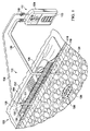
ここで主に図1を参照すると、同時にドレーン136を通して創傷滲出液を収集しながら、線状創傷114を含む組織部位112を治療する減圧治療システム110の例示的実施形態が示されている。組織部位112は線状創傷114に関係がある。組織部位112は、骨組織、脂肪組織、筋組織、皮膚組織、脈管組織、結合組織、軟骨、腱、靭帯、または任意の他の組織を含む、任意のヒト、動物、または他の生物の体の組織とし得る。組織部位112の治療には、流体、例えば滲出液の除去を含み得る。組織部位112は、表皮116にあるとして示すが、場合によっては、同様に真皮118、および皮下組織120を含み得る。減圧治療システム110はまた、他の組織部位と共に使用してもよい。
Referring now primarily to FIG. 1, an exemplary embodiment of a reduced
減圧治療システム110は、創傷ドレッシングアセンブリ122および減圧サブシステム111を含む。減圧治療システム110を、線状創傷114を覆って配置された減圧創傷ドレッシングアセンブリ122との関連で示すが、減圧治療システム110を、開放創を含む他の組織部位でも使用し得ることを理解されたい。創傷ドレッシングアセンブリ122は、マニホールドの機能を果たすドレッシングボルスター124と、オーバードレープ126と、減圧供給導管130に適合する第1の減圧インターフェース128とを含む。減圧供給導管130は、減圧サブシステム111に流体的に結合される。
The reduced
機能的には、減圧サブシステム111によって発生した減圧が、減圧供給導管130を通って第1の減圧インターフェース128に供給される。例示的一実施形態では、第1の減圧インターフェース128は、KCI(San Antonio、Texas)から入手可能なT.R.A.C.(登録商標)PadまたはSensa T.R.A.C.(登録商標)Padである。第1の減圧インターフェース128によって、減圧をドレッシングボルスター124に供給できる。別の実施形態では、減圧インターフェース128は使用されない。その代わりに、ルーメン(すなわち導管)が、オーバードレープ126を通して直接ドレッシングボルスター124に配置される。
Functionally, the reduced pressure generated by the reduced
創傷ドレッシングアセンブリ122は、減圧で治療されるべき組織部位112を含む領域を覆って流体シールを提供する。流体シールは、特定の1つまたは複数の減圧源または関連のサブシステムによって与えられる減圧を所望の部位に維持するのに適切なシールである。
The
創傷ドレッシングアセンブリ122はまた、第2の減圧インターフェース132を含む。第2の減圧インターフェース132は、接着剤、ボンディング、溶接(例えば、超音波溶接、熱溶接、またはRF溶接)、またはセメント剤(図示せず)によってオーバードレープ126に締結される。第2の減圧インターフェース132は、組織部位112を覆う流体シールの完全性を維持する一方、皮下供給導管134がドレッシングボルスター124およびオーバードレープ126を通過できるようにする。実施形態では、第2の減圧インターフェース132は、オーバードレープ126に溶接または接着される成形プラスチック部品を含む。
The
図1の第2の減圧インターフェース132は、使用者または治療の施術者が第2の減圧インターフェース132の外面に力を及ぼして、皮下供給導管134を、創傷ドレッシングアセンブリ122を通って送ることができるように構成される。同時に、使用者は、第2の減圧インターフェース132の個所で、皮下供給導管134をオーバードレープ126に十分な力で押し付けて、オーバードレープ126を破ることができる。第2の減圧インターフェース132はオーバードレープ126を補強しているため、第2の減圧インターフェース132の外側で流体シールを提供するオーバードレープ126の能力を低下させることなく、オーバードレープが破られるようにする。一実施形態では、第2の減圧インターフェース132の箇所においてオーバードレープにアパーチャが形成され、創傷ドレッシングアセンブリ122を通る経路を容易にする。
The second
第2の減圧インターフェース132は、いくつもの形状およびサイズをとり得る。例えば、第2の減圧インターフェース132は、実質的に図1に示すような形状にしてもよく、第2の減圧インターフェース132は、平坦な上面および底面と、アパーチャ168とを含む。アパーチャ168は、皮下供給導管134が第2の減圧インターフェース132を通って挿入されるとき、皮下供給導管134に対して半径方向の圧縮力を生成するようなサイズにされ得る。例えば、アパーチャ168と皮下供給導管134との間に締り嵌めが形成され得る。例示的一実施形態によれば、第2の減圧インターフェース132は、インターフェース本体133から形成されたニップル131を含み、ニップルは、内径D1のアパーチャ168を備え得る。皮下供給導管134は、外径D2を有し得る。これら直径は、式D1<D2の関係にある。D1はD2をわずかに下回り、それにより、締り嵌めによる流体シールが形成される。別の実施形態では、D1は、D2に等しくし得る。
The
第2の減圧インターフェース132をまた、第2の減圧インターフェース132の厚さがアパーチャにおいて厚くなり、かつ次第に薄くなって、外縁部において最小厚さとなるように、先細にし得る。第2の減圧インターフェース132の厚さは、縁部からアパーチャ168の縁まで線形にまたは曲線的に次第に厚くなり得る。第2の減圧インターフェース132はまた、丸みを帯びた、またはドームタイプの形状を有し得る。他の形状も可能である。
The
皮下供給導管134は、ドレーン136から、創傷滲出液が皮下組織部位138から流出できるようにする働きをする。皮下供給導管134は、減圧サブシステム111または第2の減圧サブシステム(図示せず)に流体的に結合している。それゆえ、減圧供給導管130および皮下供給導管134の双方とも、減圧をもたらし、かつ減圧サブシステム111に結合し得る。ここで、減圧供給導管130は減圧サブシステム111に結合されて、組織部位112に減圧療法を行う。皮下供給導管134はまた、減圧サブシステム111または別個の減圧サブシステム(図示せず)に結合して、ドレーン136から流体または滲出液を吸い出す。
減圧は、治療が施されている組織部位における周囲圧力を下回る圧力である。ほとんどの場合、この減圧は、患者がいる場所の気圧を下回る。あるいは、減圧は、組織部位の静水圧を下回り得る。他に指定のない限り、本明細書で述べる圧力の値は、ゲージ圧である。供給される減圧は、一定であってもまたは変動しても(パターン化またはランダム)よく、連続的にまたは断続的に供給され得る。本明細書での使用に一致して、他に指定のない限り、減圧または真空圧の上昇は、一般に、絶対圧の相対的な低下を指す。 Depressurization is a pressure below the ambient pressure at the tissue site being treated. In most cases, this reduced pressure is below the air pressure where the patient is. Alternatively, the reduced pressure can be below the hydrostatic pressure of the tissue site. Unless otherwise specified, the pressure values mentioned herein are gauge pressures. The reduced pressure supplied can be constant or variable (patterned or random) and can be supplied continuously or intermittently. Consistent with the use herein, unless otherwise specified, an increase in vacuum or vacuum generally refers to a relative decrease in absolute pressure.
一部の実施形態では、線状創傷114の組織部位112においては、皮下組織部位138とは異なる量の減圧が望ましいとし得る。そのような実施形態では、皮下供給導管134および減圧供給導管130は、異なる減圧源に流体的に結合され、かつそれぞれに関連付けられた異なる液溜めを含み得る。あるいは、供給導管130、134は、1つまたは複数の圧力調整器140を通して同じ減圧サブシステム111に結合されてもよく、それにより、単一の減圧サブシステム111が、異なる量の減圧を各導管に供給できるようにする。一部の実施形態では、線状創傷114の組織部位112において、皮下組織部位138と同じ量の減圧が望まれてもよい。これらの実施形態では、皮下供給導管134および減圧供給導管130は、圧力調整器を必要とせずに、同じ減圧源109に流体的に結合され得る。
In some embodiments, a different amount of reduced pressure may be desirable at the
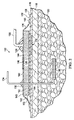
ここで主に図2を参照すると、図1の創傷ドレッシングアセンブリ122の垂直断面図が示されている。図示の創傷ドレッシングアセンブリ122は、任意選択的な内側快適層142を含み、この内側快適層は、ドレッシングボルスター124に結合されていてもよく、かつドレッシングボルスター124の材料と患者の表皮116との間にある。創傷ドレッシングアセンブリ122はまた、(緯度の方向または長手方向の)可撓性のノッチ144を含み、ドレッシングボルスター124に可撓性を加え得る。さらに、創傷ドレッシングアセンブリ122のオーバードレープ126は、襞146またはノッチまたは隆起を含み、創傷ドレッシングアセンブリ122に可撓性を加え得る。
Referring now primarily to FIG. 2, a vertical cross-sectional view of the
減圧供給導管130とドレッシングボルスター124とに流体的に結合される第1の減圧インターフェース128に加えて、創傷ドレッシングアセンブリ122はまた、第2の減圧インターフェース132を含む。第2の減圧インターフェース132は、皮下供給導管134の存在に適応するように機能する。皮下供給導管134は、減圧治療システム110が組織部位112に減圧を行う能力を妨げることなく、ドレーン136に流体的に結合されるドレーンチューブの役目を果たす。第2の減圧インターフェース132は、組織部位112における減圧療法を妨げるまたは停止させる漏れを生じることなく、減圧源をドレーン136に流体的に結合する。
In addition to the first reduced
創傷ドレッシングアセンブリ122のドレッシングボルスター124は、第1の側面148および第2の内側に向く側面150を有する。ドレッシングボルスター124は、真空空間、または治療空間をもたらす任意のボルスター材料またはマニホールド材料、例えば多孔質かつ透過性の発泡体または発泡体様材料、経路を備えて形成された部材、グラフト、またはガーゼから形成し得る。より具体的で非限定的な例として、ドレッシングボルスター124は、減圧下での創傷液の浸透性を良好にできる網状の連続気泡のポリウレタンまたはポリエーテル発泡体とし得る。使用されてきたそのような発泡材料の1つは、Kinetic Concepts,Inc.(KCI)(San Antonio、Texas)から入手可能なVAC(登録商標)GranuFoam(登録商標)材である。マニホールド材料が減圧を分配する働きをするという条件で、任意の材料または材料の組み合わせをマニホールド材料に使用し得る。
The dressing bolster 124 of the
マニホールドは、一般的に、組織部位に対して減圧を行ったり、流体を供給したり、または組織部位から流体を除去したりするのを支援するために設けられる物体または構造である。マニホールドは、一般に、複数の流路または流れ経路を含む。複数の流路は相互に接続されて、マニホールドの周りの組織領域に提供されるかまたはそこから除去される流体の分配を改善し得る。マニホールドの例は、限定されるものではないが、流路を形成するように配置された構造要素などを有する装置、気泡質の発泡体、例えば連続気泡発泡体、多孔性組織集合体、および液体、ゲル、および流路を含むまたは硬化して流路を含む発泡体などを含み得る。一部の実施形態では、マニホールドは、複数の層または基材によって形成し得る。さらに、複数の層を備えるマニホールドの一部の実施形態では、使用中、患者の最も近くにある層は、最も親水性が低くかつ最も疎水性である材料である。 A manifold is generally an object or structure that is provided to assist in reducing the pressure, supplying fluid, or removing fluid from a tissue site. The manifold generally includes a plurality of flow paths or flow paths. Multiple flow paths may be connected to each other to improve the distribution of fluid provided to or removed from the tissue region around the manifold. Examples of manifolds include, but are not limited to, devices having structural elements and the like arranged to form flow paths, cellular foams such as open cell foams, porous tissue assemblies, and liquids , Gels, and foams that contain channels or harden to contain channels. In some embodiments, the manifold may be formed by multiple layers or substrates. Further, in some embodiments of a manifold with multiple layers, in use, the layer closest to the patient is the least hydrophilic and the most hydrophobic material.
GranuFoam(登録商標)材の網状細孔は、マニホールドの機能を果たすのに役立つが、一方、他の材料を使用してもよい。場合によっては、GranuFoam(登録商標)材よりも密度の高いまたは低い(細孔サイズの小さい)材料が望ましいとし得る。多くの考えられる材料の中で、以下のものを使用し得る:GranuFoam(登録商標)材、Foamex(登録商標)テクニカルフォーム(technical foam)(www.foamex.com)、ガーゼ、可撓性のチャネルを含む部材、グラフトなど。場合によっては、マイクロボンディング工程において発泡体に銀イオン(ionic silver)を添加すること、または材料に抗菌剤などの他の物質を添加することが望ましいとし得る。 The reticulated pores of the GranFooam® material serve to serve the function of the manifold, while other materials may be used. In some cases, a denser or lower (smaller pore size) material than the GranuFoam® material may be desirable. Among many possible materials, the following may be used: GranuFoam® material, Foamex® technical form (www.foamex.com), gauze, flexible channel Containing members, grafts and the like. In some cases, it may be desirable to add ionic silver to the foam in the microbonding process, or to add other substances such as antimicrobial agents to the material.
マニホールドは、一般に、流体を、マニホールドの周りの組織部位にもたらしかつそこから除去されるように分配させる、複数の流路または流れ経路を含む。ここでは、マニホールドは、皮下組織部位と接触して配置されかつ皮下組織部位に減圧を分配することができる生体適合性材料である。マニホールド材料は、減圧治療の後、患者の体に置いたままにしてもよい生体再吸収性材料を含み得る。一般的に、生体再吸収性材料は、単純な化学種に生体内で酵素的または化学的に分解されかつ代謝の排泄によって体から除去され得る材料である。好適な生体再吸収性材料は、限定されるものではないが、ポリ乳酸(PLA)とポリグリコール酸(PGA)とのポリマーブレンドを含み得る。ポリマーブレンドはまた、限定されるものではないが、ポリカーボネート、ポリフマレート、およびカプララクトン(capralactone)を含み得る。マニホールド材料は、新しい細胞増殖のための足場としての機能をさらに果たしてもよいし、または細胞増殖を促進するためにマニホールド材料と足場材料が一緒に使用されてもよい。足場は、細胞増殖または組織形成を増進させるまたは促進するのに使用される物体または構造であり、例えば、細胞増殖のテンプレートを提供する三次元の多孔質構造である。足場材料の例示的例は、リン酸カルシウム、コラーゲン、PLA/PGA、コーラルヒドロキシアパタイト(coral hydroxy apatite)、カーボネート、または加工された同種移植片材料を含む。 The manifold generally includes a plurality of flow paths or flow paths that allow fluid to be delivered to and removed from tissue sites around the manifold. Here, the manifold is a biocompatible material that can be placed in contact with the subcutaneous tissue site and distribute the vacuum to the subcutaneous tissue site. The manifold material may include a bioresorbable material that may be left on the patient's body after reduced pressure treatment. In general, bioresorbable materials are materials that can be enzymatically or chemically degraded in vivo to simple chemical species and removed from the body by metabolic excretion. Suitable bioresorbable materials can include, but are not limited to, polymer blends of polylactic acid (PLA) and polyglycolic acid (PGA). The polymer blend may also include, but is not limited to, polycarbonate, polyfumarate, and coupler lactone. The manifold material may further serve as a scaffold for new cell growth, or the manifold material and scaffold material may be used together to promote cell growth. A scaffold is an object or structure used to enhance or promote cell growth or tissue formation, eg, a three-dimensional porous structure that provides a template for cell growth. Illustrative examples of scaffold materials include calcium phosphate, collagen, PLA / PGA, coral hydroxyapatite, carbonate, or processed allograft material.
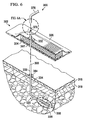
例示的一実施形態では、ドレッシングボルスター124は、以下の通り製造される。Granufoam(登録商標)材の発泡体ブロック、例えば、1.21メートル×1.8メートル×0.5メートルのブロックを、19mmの高さを有するように切断し、および鋸を使用して、図2および図6に示すような横方向の溝、または横方向の可撓性のノッチを形成する。その後、内側快適層142とし得る乾燥した層を、第2の面すなわち底面に積層するまたは取り付ける。その後、ダイカットを使用して発泡体ブロックを切断して、個々のドレッシングボルスター124を形成する。
In one exemplary embodiment, the dressing bolster 124 is manufactured as follows. Granfoam® material foam block, eg, 1.21 meter x 1.8 meter x 0.5 meter block, cut to have a height of 19 mm and using a saw 2 and a lateral groove as shown in FIG. 6, or a lateral flexible notch. Thereafter, a dry layer, which may be the
任意選択的な内側快適層142は、第1の側面152および第2の内側に向く側面154を有する。任意選択的な内側快適層142の第1の側面152は、例えば、ヒートボンド(heat bond)または任意の他の技術によって、ドレッシングボルスター124の第2の内側に向く側面150に結合され得る。内側快適層142は、一般に、ドレッシングボルスター124を患者の表皮116に隣接して配置するときに、患者に快適さをもたらす。内側快適層142は、皮膚の刺激および不快感を防止するのを支援する一方、内側快適層142を通した流体伝達を可能にする任意の材料とし得る。非限定的な例として、織りの弾性材料またはポリエステルの編みテキスタイルの基材を使用し得る。別の非限定的な例として、Milliken & Company,Inc.(Spartanburg、South Carolina)の事業部であるMilliken ChemicalからのInterDry(商標)テキスタイル材を使用し得る。内側快適層142は、銀などの抗菌物質を含んでもよく、および通気性のある乾燥した層のように作製し得る。
The optional
ドレッシングボルスター124は、ドレッシングボルスター124の第1の側面148にある、横方向の切込みとし得る複数の可撓性のノッチ144または凹部を含み得る。さらに、可撓性のノッチ144は、1つまたは複数の長手方向のノッチ、または長手方向の切込み、または他の切込みとし得る。切込みは、鋸(すなわちギザギザのある刃)、ホットナイフ、または他の装置を使用して作製され得る。可撓性のノッチは、ドレッシングボルスター124の可撓性を高め得る。可撓性が高められることは、創傷ドレッシングアセンブリ122を患者の関節の領域または別の動く領域に適用するときに、特に有用とし得る。例えば、ドレッシングボルスター124を膝に使用する場合、ドレッシングボルスター124は、撓む、または100%もしくはそれ以上伸長する必要があることがあり、および可撓性のノッチは、所望の可撓性をもたらすのを助ける。可撓性のノッチはまた、六角形、スリット、または正方形などの様々な形状をとり得る。
The dressing bolster 124 may include a plurality of
ドレッシングボルスター124は、ドレッシングボルスター124の第2の内側に向く側面150に対して直交する横方向の縁部を備えて形成され得る。横方向の縁部はまた、勾配付き縁部または角度付き縁部を備えて形成され得る。角度付きまたは勾配付きの縁部は、ドレッシングボルスターと患者の表皮116との間のせん断応力を分配し得る。ドレッシングボルスター124はまた、丸みを帯びた側面を有し得る。ドレッシングボルスター124は、ボルスターを通って形成された小さなアパーチャ、または切込みを有し、比較的小さな力で、皮下供給導管134を、ドレッシングボルスター124を通して案内し得る。
The dressing bolster 124 may be formed with a lateral edge perpendicular to the second inwardly facing
オーバードレープ126として示すシール部材は、ドレッシングボルスター124と、患者の表皮116の少なくとも一部分とを覆って、流体シールを提供し得る。そのように、オーバードレープ126は、流体シールを可能にする任意の材料から形成し得る。オーバードレープ126は、感圧接着剤などのシール装置によって、表皮116に対して、またはガスケット材料に対してシールされ得る。
A seal member, shown as
シール装置は、粘着性を有するシーリングテープ、またはドレープテープもしくは帯条片;両面ドレープテープ;感圧接着剤;糊;親水コロイド;ヒドロゲル;または他のシール手段など、多数の形態をとり得る。本明細書で説明するように、シール部材は、一般にオーバードレープ126である。テープを使用する場合、テープは、オーバードレープ126と同じ材料で、感圧接着剤が予め塗布された状態で形成され得る。感圧接着剤は、オーバードレープ126の第2の内側に向く側面158またはその一部分に塗布し得る。感圧接着剤は、オーバードレープ126と表皮116との間に流体シールをもたらすのを助ける。本明細書では、流体シールはまた、表皮116に接するガスケットを含み得る。シール部材を表皮に固定する前に、感圧接着剤を覆っている取り外し可能な帯条片、または剥離ライナーを取り除き得る。
The sealing device may take a number of forms, such as an adhesive sealing tape, or a drape tape or strip; a double-sided drape tape; a pressure sensitive adhesive; a glue; a hydrocolloid; a hydrogel; As described herein, the seal member is generally an
シール部材、またはオーバードレープ126は、エラストマー性材料、または流体シールをもたらす任意の材料もしくは物質とし得る。エラストマーの例は、限定されるものではないが、天然ゴム、ポリイソプレン、スチレンブタジエンゴム、クロロプレンゴム、ポリブタジエン、ニトリルゴム、ブチルゴム、エチレンプロピレンゴム、エチレンプロピレンジエンモノマー、クロロスルホン化ポリエチレン、多硫化ゴム、ポリウレタン、EVAフィルム、コ−ポリエステル、およびシリコーンを含み得る。さらに、シール部材材料は、シリコーンドレープ、3M Tegaderm(登録商標)ドレープ、Avery Dennisonから入手可能なものなどのアクリルドレープ、または切開用ドレープを含み得る。
The seal member, or
シール部材、すなわちオーバードレープ126は、第1のシール部材またはドレープ部分160、および第2のシール部材またはドレープ部分162を含み得る。第1のシーリングドレープ部分160は、ドレッシングボルスター124の第1の側面148の上側を覆って延在する。オーバードレープ126は、さらに、第1の側面および第2の内側に向く側面(明示せず)を有するシール部材フランジ、すなわちシール部材延長部を形成するように延在する。オーバードレープ126の一部分にはアパーチャ(明示しないが、図8の559に類似している)が形成されて、第1の減圧インターフェース128との流体連通を可能にし、この第1の減圧インターフェースは、減圧サブシステム111に流体的に結合されている。
The seal member, or
オーバードレープ延長部の第2の内側に向く側面は、第2のシーリングドレープ部分162の第1の側面(図1の向きで上面)に配置され、かつ接着剤、ボンディング、溶接(例えば、超音波溶接、熱溶接、またはRF溶接)、またはセメント剤(図示せず)などによって結合されている。あるいは、第1のシーリングドレープ部分160および第2のシーリングドレープ部分162は、一体的に形成され得る。第1のシーリングドレープ部分160は、複数の襞146、またはストレッチゾーンを含み得る。襞146によって、必要に応じて伸縮させたりまたは動かしたりするための、追加的なドレープ材料を用いることが可能となる。例えば、創傷ドレッシングアセンブリ122を関節で使用する場合に、追加的なドレープ材料は、関節を曲げるときに関節の動きに対応するのに有用とし得る。襞146によって、そのような動きを容易にする。
The second inwardly facing side of the overdrape extension is disposed on the first side (upper side in the orientation of FIG. 1) of the second
適用前、1つまたは複数の剥離部材(図示しないが、図8の581および583に類似している)が、第2のシーリングドレープ部分162の第1の側面に剥離可能に結合され得る。剥離部材は、剛性をもたらし、かつ創傷ドレッシングアセンブリ122の展開中に役に立つ。剥離部材は、一般に、第2のシーリングドレープ部分162の第1の側面に保持される流延用紙またはフィルムのいずれかである。
Prior to application, one or more release members (not shown but similar to 581 and 583 in FIG. 8) may be peelably coupled to the first side of the second
減圧サブシステム111は、多くの異なる形態をとり得る少なくとも1つの減圧源109を含む。減圧源109は、減圧治療システム110の一部として減圧をもたらす。減圧源109は、減圧供給導管130によって第1の減圧インターフェース128に流体的に結合される。
The
減圧サブシステム111は、1つまたは複数の溜め領域113またはキャニスター領域を有し得る。溜め領域113またはキャニスター領域は、1つまたは複数のフィルタを含み、空気圧系統に組織部位112または皮下組織部位138からの液体が入らないように保護し得る。疎水性または疎油性フィルタなどの介在型薄膜フィルタを、減圧供給導管130と減圧サブシステム111との間に介在させ得る。減圧サブシステム111に加えて1つまたは複数の装置を減圧供給導管130に流体的に結合し得る。例えば、除去された滲出液および他の流体を保持するための別の液溜めまたは収集部材、圧力フィードバック装置、容量検出システム、血液検出システム、感染検出システム、流量監視システム、または温度監視システムが、減圧供給導管130に結合され得る。そのような装置は、減圧サブシステム111に含まれ得るかまたはそれと一体的に形成され得る。
The
減圧サブシステム111は、減圧を供給するための任意の装置、例えば真空ポンプ、壁面吸い込み、または他の減圧源とし得る。組織部位に適用される減圧の量および性質は、一般に適用に応じて変動するが、減圧は、一般に、−5mm Hg(−667Pa)〜−500mm Hg(−66.7kPa)、より典型的には−75mm Hg(−9.9kPa)〜−300mm Hg(−39.9kPa)である。例えば、限定するものではないが、圧力は、−12、−12.5、−13、−14、−14.5、−15、−15.5、−16、−16.5、−17、−17.5、−18、−18.5、−19、−19.5、−20、−20.5、−21、−21.5、−22、−22.5、−23、−23.5、−24、−24.5、−25、−25.5、−26、−26.5kPaまたは別の圧力とし得る。
The
減圧サブシステム111によって発生した減圧は、減圧供給導管130を通って第1の減圧インターフェース128に供給される。第1の減圧インターフェース128によって、減圧を、オーバードレープ126を通ってドレッシングボルスター124まで供給できる。
The reduced pressure generated by the reduced
減圧治療システム110による治療を行う場合には、少なくともある閾値レベルの減圧が組織部位112に供給されていることを知ることが望ましいとし得る。減圧源に結合されたドレッシングの減圧計は、この作業を遂行できる。ドレッシングの減圧計はまた、オーバードレープ126に流体的に結合された別個のユニットとして、オーバードレープ126の密閉空間内からの圧力が、ドレッシングの減圧計に達するようにするか、または減圧サブシステム111の一部として第1の減圧インターフェース128と関連付けてもよい。適切な減圧が存在する場合、減圧計は凹み(collapsed)位置を推測し、かつ不適切な減圧が存在する場合、減圧計は非凹み位置を推測し得る。
When treating with the reduced
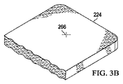
一部の実施形態では、ドレッシングボルスター124は、存在してもしなくてもよい皮下供給導管134の存在に適応するように、予め形成し得る。図3Aに示すように、ドレッシングボルスター224は、ボルスター材料の有孔切込み264または有孔シリンダーなどの解放領域を形成することによって、皮下供給導管を任意選択的に受け入れるように予め形成され得る。導管をドレッシングボルスターに容易に通すことができるように、ボルスター材料の有孔シリンダーは、ドレーンを適用するときに、手でドレッシングボルスター224から除去され得るかまたは孔があけられ得る。さらに、ボルスター材料を、様々な直径の複数の切込みのある状態にするように、穿孔することが望ましいことがあり、いずれかの予測できるドレーンチューブのサイズとほぼ同じサイズのボルスター材料の部片を、手で取り除くことができるようにする。
In some embodiments, the dressing bolster 124 may be preformed to accommodate the presence of a
あるいは、ドレッシングボルスター224における変形が若干多めに許容される場合、ドレッシングボルスター224は、図3Bに示すようなボルスター材料に作製された十字形の切込み266の形態の解放領域を有し、ドレーンチューブが通過できるようにし得る。有孔切込み264は、ドレッシングボルスター224を通って送られる導管またはチューブのタイプに依存して任意の様々な有孔の形状またはサイズとし得る。ドレッシングボルスター224が任意選択的な快適層、例えば図2の内側快適層142を備えて組み立てられる場合、孔あけまたは十字形の切込みはまた、内側快適層142に形成されて、ドレッシングボルスター材料の有孔切込み264または十字形の切込み266を補完する。
Alternatively, if the dressing bolster 224 is allowed to be slightly more deformed, the dressing bolster 224 has a release region in the form of a
ここで主に図4を参照すると、解放領域を有するドレッシングボルスター224を組み込む創傷ドレッシングアセンブリ222が示されている。創傷ドレッシングアセンブリ222の構成要素は、有孔切込み264または十字形の切込み266(図3B)を有して、ドレッシングボルスター材料をシリンダー状に簡単に除去できるようにし、皮下供給導管がドレッシングボルスター224を通過できるようにし得る。そのような実施形態では、有孔切込み264または十字形の切込み266は、創傷ドレッシングアセンブリの一部のみを通って延在するため、皮下供給導管が存在してもしなくても、流体シールが組織部位に維持され得る。創傷ドレッシングアセンブリは、第2の減圧インターフェース232を含み、皮下供給導管が存在する場合でも、第2の減圧インターフェース232と皮下供給導管の境界に流体シールを形成する。第2の減圧インターフェース232は、組織部位と周囲環境との間のオーバードレープ226によって設けられたシールを補強する働きをし得る。ここで、第2の減圧インターフェース232はまた、アパーチャ268を含み、導管のあるセクションを、第2の減圧インターフェース232を通して送ることができるようにする。
Referring now primarily to FIG. 4, a
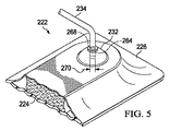
ここで主に図5を参照すると、第2の減圧インターフェース232は、上述の通り、エラストマー性の特性を備える材料、すなわちエラストマーを使用して成形され得る。第2の減圧インターフェース232の材料の弾性は、第2の減圧インターフェース232のアパーチャ268を拡大させて、導管または皮下供給導管234のあるセクションを、アパーチャ268に通過させることができるようにする。一実施形態では、アパーチャ268の直径は、第2の減圧インターフェース232を通して送られ得る導管の直径よりもわずかに小さいとし得る。この寸法のわずかな重なりによって締り嵌めを達成し、皮下供給導管234が第2の減圧インターフェース232を通して送られるときに、アパーチャ268を少量変形させるようにし得る。
Referring now primarily to FIG. 5, the
変形する結果、第2の減圧インターフェース232のエラストマー性の特性(すなわち弾性)によって、アパーチャ268の表面と皮下供給導管234との間に半径方向の圧縮力270を発生させ得る。それにより、半径方向の圧縮力270は、第2の減圧インターフェース232と皮下供給導管234の境界に流体シールを形成し、それにより、組織部位と周囲環境との圧力差を保ち得る。場合によっては、追加的な材料を使用して、第2の減圧インターフェース232と皮下供給導管234のこのシールされた境界を形成または強化し得る。例えば、接着剤または1つまたは複数のガスケット(例えば、oリング)をアパーチャ268の表面と皮下供給導管234の外面との間に設置して、流体シールの強度を高めてもよい。
As a result of the deformation, the elastomeric properties (ie, elasticity) of the second reduced
ここで主に図6を参照すると、線状創傷(図示せず)を有する組織部位を治療する減圧システム300の別の実施形態が示されている。減圧システム300は第2の減圧インターフェース332を含み、この第2の減圧インターフェースは、組織部位(図示せず)に適用される創傷ドレッシングアセンブリ322に組み込まれている。組織部位は、皮下供給導管334の第1の導管セグメント335に近接している。場合によっては、皮下供給導管334の第1の導管セグメント335を皮下組織320に取り付けたままにし、かつ挿入された導管を覆って創傷ドレッシングアセンブリ322を適用できるようにする一方、周囲の組織を可能な限り妨害しないようにすることが望ましいとし得る。ここで、創傷ドレッシングアセンブリ322を適用して、患者の表皮において皮下供給導管334が患者の表皮または皮膚から出る個所付近に配置された線状創傷(図示せず)に減圧を供給するための、よりモジュール式の解決法を示す。
Referring now primarily to FIG. 6, another embodiment of a reduced
皮下供給導管334は第1の導管セグメント335を含み、第1の導管セグメントは、患者の表皮316の上方を短い距離(例えば、約10センチメートル)のみ延在し、かつその後、導管の追加的なセクション、例えば、第2のセグメント376またはアダプタ397に結合され得る。組み合わせられた導管セグメント335、397、および376(または一部の実施形態では、335および376)を使用して、収集した流体を排出する。皮下供給導管334の第1の導管セグメント335は、患者に取り付けられたままであり、かつ表皮316から十分に突出して、第1の導管セグメント335の端部分396と第2の導管セグメント376の端部分374との間の封止結合を可能にするようなサイズにされ得る、トリミングされ得る、または他の方法で構成され得る。第2の導管セグメント376は、減圧源およびドレナージ収集領域(図示せず)に流体的に結合され得る。皮下供給導管334の第2の導管セグメント376は、第1の導管セグメント335を取り外さずに、取り外されて交換され得る。
第1の導管セグメント334と第2の導管セグメント376との間の結合は、いくつもの方法で生じ得る。例えば、効果的な結合は、第1の導管セグメント334の端部分335と第2の導管セグメント376との間に締り嵌めを提供することによって、達成され得る。この結合部は、直接結合としても、または中間導管セグメントを含むアダプタ397、すなわち結合器を使用して形成された結合としてもよい。アダプタ397を使用しない場合、第1の導管セグメントは、創傷ドレッシングアセンブリ322および第2の減圧インターフェース332を通って突出するようなサイズにされ、および第2の導管セグメント376の端部分(または遠位端部)374は、第1の導管セグメント335の端部分396にぴったりと合うようなサイズにされ得る。導管セグメント(335および376)の重なりによって、液密シールを形成する。
The coupling between the
アダプタ397は、第1の導管セグメント335および第2の導管セグメント376の双方と流体シールを形成するように適合された先細の導管端部を有する結合器とし得る。あるいは、アダプタ397を第1の導管セグメント335および第2の導管セグメント376に結合するために使用された任意のシール手段は、第1の導管セグメント335を第2の導管セグメント376に直接結合するために使用される。例えば、第1の導管セグメント335と第2の導管セグメント376の重なり合う部分は、一緒に結合部を形成せざるを得ないようにされ得る。さらに、第2の導管セグメント376は、図6Aに提案するようなアダプタ397の端部セグメント378上の溝付き導管セグメント380または第1の導管セグメント335の溝付きセグメントを収容し得る。導管セグメントの端部分はまた、他の物理的特徴を含み、シールの形成および保持を支援し得る。例えば、小さな導管部分の外面に角度を付けても、または先細にしてもよいし、および大きな直径の導管部分の内面が相補的な溝またはテーパを有して、対向する導管セグメントを収容して封止してもよい。
The
固定部材384が任意選択的に含まれ、第1の導管セグメント335を表皮316に対して固定して、ドレッシングアセンブリ322を適用している最中の周囲組織の刺激を最小限にし得る。そのようなものとして、固定部材384は、非常に可撓性がありかつ透湿性のある低硬度の材料のものとし、下にある真皮に対する刺激および損傷を実質的になくすかまたは少なくし得る。固定部材384の材料は、焼結させたゴムまたはシリコーン重合体部材などの多孔質材とし得る。固定部材384は、接着剤または他の取付装置を使用して表皮316に接着し得る。固定部材384は、第1の導管セグメント335を固定するのを助け、第1の導管セグメント335の不要な動きを防止する。固定部材384は、リング形状を呈してもよく、または図6に示すようにフランジ形状を有してもよい。そのような構成では、固定部材384は、中間導管セグメントの機能を果たしかつ第1の導管セグメント334と第2の導管セグメント376との間の封止結合を形成してもよいし、または導管セグメント335および376を単に固定する通り抜け装置としてもよい。
An anchoring
ここで主に図7を参照すると、第2の減圧インターフェース432を含む、線状創傷を有する組織部位を治療する別の減圧システム400が示されている。創傷ドレッシングアセンブリ422は、多くの点で図2の創傷ドレッシングアセンブリ122に類似している。しかしながら、オーバードレープ426はよりゆったりと覆っており、かつ第2の減圧インターフェース432を覆って形成し、かつoリング486やクランプによって皮下供給導管434に対して固定されることができる。第2の減圧インターフェース432は、インターフェース本体433から形成されるニップル431を含み得る。
Referring now primarily to FIG. 7, another reduced
ここで主に図8を参照すると、減圧による組織部位の治療において適用するための創傷ドレッシングアセンブリ522の一部分の、分解斜視図が示されている。組織部位は、皮下組織部位、線状創傷、創傷部(area wound)、または他の創傷またはグラフトとし得る。図8に示す創傷ドレッシングアセンブリ522は、展開前状態にある分解図で示す。創傷ドレッシングアセンブリ522は、大部分の点で図1および図2の創傷ドレッシングアセンブリ122に類似している。対応する部分を示すために、参照符号を100の桁だけ変えて大きくしてあり、さらなる説明はしない。
Referring now primarily to FIG. 8, an exploded perspective view of a portion of a
創傷ドレッシングアセンブリ522はドレッシングボルスター524を含み、このドレッシングボルスターは、同様に、ドレッシングボルスター524の表面に対して横方向および長手方向の双方に可撓性のノッチ544を含み得る。ドレッシングボルスター524の第1の側面548はオーバードレープ526で覆われており、このオーバードレープは、第1のドレープ部分560および第2のドレープ部分562を含み得る。第1のドレープ部分560は、襞546およびドレープアパーチャ559を含む。第2のドレープ部分562は、ドレッシングボルスター524の少なくとも一部分への、または患者の表皮に直接適用される内側快適層542への開口部を提供する治療領域アパーチャ588を備えて形成され得る。第2のドレープ部分562は第1の側面587を有し、かつ第1の側面587の一部分に接着剤589が塗布されている。接着剤589は、主に製造中に使用して、ドレッシングボルスター524(または存在する場合には内側快適層542)を、組立の最中、第2のドレープ部分562に当てるようにし、かつまた、使用中にドレッシングボルスター524を保持するのを支援するために使用し得る。ドレッシングボルスター524または内側快適層542を接着剤589に適用する前、接着剤589は、中心剥離可能部材585によって覆われている。第1の側面587の接着剤589の外側には剥離可能部材583があり、展開中のオーバードレープ526に剛性をもたらす。
The
第2のドレープ部分562の第2の内側に向く側面(明示しないが、第1の側面587に対向する側面)は、接着剤で覆われ得る。展開前状態では、この接着剤は、底部剥離部材590および側部剥離部材583によって覆われている。
The second inwardly facing side of second drape portion 562 (not explicitly shown, but the side facing first side 587) may be covered with an adhesive. In the pre-deployment state, this adhesive is covered with the
一旦組み立てられると、創傷ドレッシングアセンブリ522は、図1のドレッシングアセンブリ122と似ている。使用および設計は変わり得るが、例示的一実施形態では、創傷ドレッシングアセンブリ522は、下記の通り展開され得る。患者に皮下供給導管(図示せず)が挿入されてから、創傷ドレッシングアセンブリ522を通して第2の側面から第1の側面まで遠位端部が配置される。一実施形態では、皮下供給導管は、快適層542(存在する場合には)にある予め形成された切込み566を通して、および任意選択的にドレッシングボルスター524を通して押し込まれる。
Once assembled, the
底部剥離ライナー590が取り除かれ、かつ第2のドレープ部分562の第2の内側に向く側面上にある、露出された接着剤を、一方の端部から始めて患者の表皮の一部分にくっつけて置いて、創傷ドレッシングアセンブリ522を、線状創傷を覆って配置し得る。第2のドレープ部分562を順調に適用した後、側部剥離部材583を取り除く。オーバードレープ526の第1の側面587上にある剥離部材581を取り除く。第1の減圧インターフェース528を、第1のドレープ部分560のドレープアパーチャ559に結合する。第2の減圧インターフェース532も、ドレッシングボルスター524および内側快適層542(存在する場合)に作られた、予め形成された切込み566の中心と同軸の、ある個所において、ドレープ(製造中に既に適用されていない場合)に接着させて、ドレーンの存在に適応し得る。中心剥離部材585は、製造中に取り除かれる。
With the
使用者または治療の施術者は、創傷ドレッシングアセンブリ522のフットプリント(footprint)内にドレーンまたは他の皮下供給チューブを備える第2の減圧インターフェース532を含む創傷ドレッシングアセンブリ522を適用し得る。一実施形態では、第2の減圧インターフェースは、製造中に創傷ドレッシングアセンブリに取り付けられる。別の実施形態では、第2の減圧インターフェース532は、使用時に追加され得る別個のアイテムである。例えば、ドレーンチューブは、外科創傷の端部から突出しているため、使用者は、第2の減圧インターフェース532が望まれていることを認識して、第2の減圧インターフェース532を適用する。
A user or treatment practitioner may apply a
一実施形態の適用では、創傷ドレッシングアセンブリの選択後、使用者は、ドレッシングボルスターの予め形成された切込み566がドレーンの皮下供給導管と位置合わせされるように、創傷ドレッシングアセンブリ522を方向付ける。その後、使用者は、使用者がオーバードレープ526の抵抗を感じるまでドレッシングボルスターを通して導管を押す。使用者は、成形された減圧インターフェースに力を加えて、ドレープを通して導管を押し、ドレープは、限界力を受けると、破れる。限界力を加えるために、減圧インターフェースは、インターフェースを形成する材料を使用者が把持してそれを導管に対して押し付けるのに適切なサイズである必要があり得る。例えば、第2の減圧インターフェースは、導管が通過するアパーチャを半径方向に少なくとも1センチメートル越えて延在する必要があり得る。その後、使用者は、創傷ドレッシングアセンブリ522を通して十分な量の導管を引き出して、導管を受口に接続する前に創傷ドレッシングアセンブリ522を配置できるようにする。この適用方法は、第2の減圧インターフェースおよび破れたオーバードレープの双方に、導管の周囲で半径方向の圧縮を生じて、導管と創傷ドレッシングアセンブリ522の境界に流体シールを形成する必要がある。
In one embodiment application, after selection of the wound dressing assembly, the user orients the
同様の実施形態では、第2の減圧インターフェース532は、展開時に追加され得る。皮下供給導管が創傷部位付近に存在する場合、導管は、予め形成された切込み566を通して、または同様の新しく形成された切込みを通して送られ得る。同様に、導管の遠位端部は、穿孔されるように設計されるオーバードレープ526の一部分を通して、またはドレープに新しく形成された切り口を通して押し込まれ得る。第2の減圧インターフェース532は、皮下供給導管の遠位端部を覆って配置され、皮下供給導管を摺動し、かつオーバードレープ526の外面に接着され得る。その後、皮下導管の遠位端部を減圧源に結合し得る。減圧供給導管は、第1の減圧インターフェース528を減圧源に結合し得る。減圧源は、両インターフェースに対して同じであってもよいし、または所望により、異なる減圧源がそれぞれのインターフェースに取り付けられてもよい。
In a similar embodiment, a second reduced
ここで主に図9を参照すると、代替的な形状を有するドレッシングアセンブリ622が示されている。ドレッシングアセンブリ622は、身体の異なる部分に減圧を適用するようなサイズにされかつそのように構成され、かつそれに応じてサイズおよび形状が変化し得る。同様に、ドレッシングアセンブリ622のサイズは、予想される創傷のサイズに従って変化し得る。ここで、上述の特徴および属性の多くを有するドレッシングアセンブリ622を示し、ドレッシングボルスター624、第1の減圧インターフェース628、第1の減圧導管630、第2の減圧インターフェース632、および皮下供給導管634を含む。
Referring now primarily to FIG. 9, a dressing assembly 622 having an alternative shape is shown. The dressing assembly 622 is sized and configured to apply reduced pressure to different parts of the body, and may vary in size and shape accordingly. Similarly, the size of the dressing assembly 622 may vary according to the expected wound size. Here, a dressing assembly 622 having many of the features and attributes described above is shown, including a dressing bolster 624, a
ドレーンチューブのための経路の形成を容易にすることに加え、第2の減圧インターフェース632はまた、創傷部位に追加的な治療および診断的適用を行うように機能し得る。例えば、第2の皮下供給導管634を、ドレーンに適応することに加え、外部の診断装置に取り付けられた小型のワイヤーセンサを使用して創傷部位を監視するために使用し得る。同様に、第2の減圧インターフェース632によって、近くにある皮下創傷部位に減圧療法を行うことを可能にし得る。そのような適用では、皮下供給導管634を使用して、マニホールド材料を、骨損傷などの皮下組織部位に届けることができ、そこにマニホールド材料および皮下供給導管を流体的に結合できる。
In addition to facilitating the formation of a pathway for the drain tube, the second reduced
マニホールド材料を届けた後、皮下供給チューブ634は、減圧源(図示せず)に結合されて、骨または脊髄損傷などの皮下組織部位に減圧を供給し得る。そのようなものとして、第2の減圧インターフェース632を追加することによって、単一の創傷ドレッシングアセンブリおよび減圧源を使用して、2つの別個の組織部位に減圧療法を行うことができる。
After delivering the manifold material, the
本発明およびその利点を特定の例示的非限定的な実施形態に照らして開示したが、添付の特許請求の範囲で定義した本発明の範囲から逸脱せずに、様々な変更、代替、置換、および修正をなし得ることを理解されたい。いずれか一つの実施形態に関連して説明された任意の特徴はまた、任意の他の実施形態にも適用可能であり得ることを理解されたい。 Although the invention and its advantages have been disclosed in the context of certain exemplary, non-limiting embodiments, various changes, substitutions, substitutions, and the like can be made without departing from the scope of the invention as defined in the appended claims. It should be understood that modifications can be made. It should be understood that any feature described in connection with any one embodiment may also be applicable to any other embodiment.
上述の利益および利点は、一実施形態に関連し得ること、またはいくつかの実施形態に関連し得ることを理解されたい。「1つの(an)」品目への言及は、1つまたは複数のそれら品目を指すことをさらに理解されたい。 It should be understood that the benefits and advantages described above may relate to one embodiment or may relate to several embodiments. It should be further understood that reference to “an” item refers to one or more of those items.
本明細書で説明した方法のステップは、任意の好適な順序で、または適切な場合には同時に実施し得る。 The method steps described herein may be performed in any suitable order or simultaneously, where appropriate.
適切な場合には、上述の例のいずれかの態様を、説明の任意の他の例の態様と組み合わせて、類似のまたは異なる特性を有しかつ同じまたは異なる問題に対処する別の例を形成する。 Where appropriate, any aspect of the above example is combined with any other example aspect of the description to form another example having similar or different characteristics and addressing the same or different issues To do.
好ましい実施形態の上述の説明は例示にすぎず、当業者は様々な修正をなし得ることを理解されたい。上述の明細書、例、およびデータは、本発明の例示的な実施形態の構造および使用の完全な説明を提供する。本発明の様々な実施形態を、ある程度詳細に、または1つまたは複数の個々の実施形態を参照して上記で説明したが、当業者は、特許請求の範囲から逸脱せずに、開示の実施形態に多数の修正をなすことができる。 It should be understood that the above description of the preferred embodiments is exemplary only, and that various modifications may be made by those skilled in the art. The above specification, examples and data provide a complete description of the structure and use of exemplary embodiments of the invention. Although various embodiments of the present invention have been described above in some detail or with reference to one or more individual embodiments, those skilled in the art will recognize that the disclosed embodiments can be practiced without departing from the scope of the claims. Numerous modifications can be made to the form.
Claims (14)
医療用ボルスター材料から形成されたドレッシングボルスターであって、患者の表皮に配置するためのものでありかつ前記線状創傷を一面に覆うようなサイズにされたドレッシングボルスターと;
前記ドレッシングボルスター、および前記患者の表皮の一部分を覆って流体シールをもたらすためのオーバードレープと;
減圧源と;
前記ドレッシングボルスターおよび前記減圧源に流体的に結合された第1の減圧インターフェースであって、前記ドレッシングボルスターに減圧を供給するための第1の減圧インターフェースと;
前記減圧源と前記第1の減圧インターフェースを流体的に結合するための減圧供給導管と;
前記オーバードレープに結合された第2の減圧インターフェースであって、皮下供給導管を受け入れかつ前記皮下供給導管の周囲に流体シールを形成するようなサイズにされかつそのように構成された第2の減圧インターフェースと
を含み、
前記オーバードレープは、前記ドレッシングボルスターと前記第2の減圧インターフェースの間に配置されており;
前記第2の減圧インターフェースは、前記オーバードレープを補強して当該オーバードレープが前記皮下供給導管によって破られると、組織部位の周囲の前記流体シールを維持するように構成されていることを特徴とする、減圧システム。 In a reduced pressure system for treating a tissue site having a linear wound,
A dressing bolster formed from a medical bolster material for placement on the epidermis of a patient and sized to cover the linear wound;
An overdrape to provide a fluid seal over a portion of the dressing bolster and the patient's epidermis;
A reduced pressure source;
A first reduced pressure interface fluidly coupled to the dressing bolster and the reduced pressure source, the first reduced pressure interface for supplying reduced pressure to the dressing bolster;
A reduced pressure supply conduit for fluidly coupling the reduced pressure source and the first reduced pressure interface;
A second vacuum interface coupled to the overdrape, wherein the second vacuum interface is sized and configured to receive a subcutaneous supply conduit and to form a fluid seal around the subcutaneous supply conduit. Interface,
The overdrape is disposed between the dressing bolster and the second vacuum interface;
The second reduced pressure interface is configured to reinforce the overdrape and maintain the fluid seal around a tissue site when the overdrape is breached by the subcutaneous delivery conduit. , Decompression system.
第1の面および第2の内側に向く面を有し、かつ治療領域アパーチャ内に形成された内側層であって、前記内側層の前記第1の面が、少なくとも一部は前記ドレッシングボルスターの前記第2の面に結合され、前記内側層が、前記皮下供給導管を受け入れるように予め切り込まれている、内側層
を含むことを特徴とする、減圧システム。 4. The decompression system according to any one of claims 1 to 3, wherein the dressing bolster has a first surface and a second inwardly facing surface for deployment so as to cover the patient's epidermis. And is sized to substantially cover the linear wound; and further:
An inner layer having a first surface and a second inwardly facing surface and formed within a treatment area aperture, wherein the first surface of the inner layer is at least partially of the dressing bolster. A reduced pressure system, characterized in that it includes an inner layer coupled to the second surface, the inner layer being pre-cut to receive the subcutaneous delivery conduit.
通路および遠位端部を有するマニホールド供給チューブであって、前記遠位端部は、前記皮下供給導管に挿入されかつ第2の組織部位に隣接して配置されるように構成されている、マニホールド供給チューブと;
前記マニホールド供給チューブを通して前記第2の組織部位まで供給可能な流動性材料であって、前記第2の組織部位に隣接するボイドを埋めることができ、前記第2の組織部位と流体連通する複数の流路を有するマニホールドを形成する、流動性材料と;
前記マニホールドの前記複数の流路と流体連通できる第2の減圧供給導管と
を含むことを特徴とする、減圧システム。 6. The decompression system according to claim 1 or any one of claims 1 to 5, wherein the tissue site is a first tissue site, the reduced pressure supply conduit is a first reduced pressure supply conduit, and the reduced pressure system. The system further:
A manifold supply tube having a passage and a distal end, wherein the distal end is configured to be inserted into the subcutaneous supply conduit and positioned adjacent to a second tissue site. A supply tube;
A flowable material that can be supplied through the manifold supply tube to the second tissue site, can fill a void adjacent to the second tissue site, and is in fluid communication with the second tissue site. A flowable material forming a manifold having a flow path;
And a second reduced pressure supply conduit in fluid communication with the plurality of flow paths of the manifold.
前記皮下供給導管が第1の導管セグメントおよび第2の導管セグメントを含み;および
前記第2の減圧インターフェースがアダプタを含み、前記アダプタが:
前記第1の導管セグメントの端部分を受け入れ;
前記第2の導管セグメントの端部分を受け入れ;および
前記第1の導管セグメントと前記第2の導管セグメントとの間の流体結合を維持するようなサイズにされかつそのように構成されていることを特徴とする、減圧システム。 The decompression system according to claim 1 or any one of claims 1 to 8,
The subcutaneous delivery conduit includes a first conduit segment and a second conduit segment; and the second vacuum interface includes an adapter, the adapter comprising:
Receiving an end portion of the first conduit segment;
Receiving an end portion of the second conduit segment; and sized and configured to maintain a fluid coupling between the first conduit segment and the second conduit segment. A reduced pressure system.
第1の面と;
第2の面であって;
外周;
前記成形プラスチックのシリンダー状部分に形成されたアパーチャ
を有する第2の面と;
を有し、
前記アパーチャが、導管を受け入れかつ前記導管の外周に対して半径方向の圧縮力を発生させるようなサイズにされており;および
前記第2の面が、前記第2の面と減圧創傷ドレッシングアセンブリのオーバードレープとの間に流体シールを形成する接着剤を含むことを特徴とする、減圧システム。 9. The decompression system according to claim 1 or any one of claims 2 to 8, wherein the second decompression interface includes a cylindrical portion of molded plastic, the cylindrical portion of molded plastic being
The first aspect;
The second aspect;
Outer periphery;
A second surface having an aperture formed in a cylindrical portion of the molded plastic;
Have
The aperture is sized to receive a conduit and generate a radial compressive force against an outer periphery of the conduit; and the second surface includes the second surface and a reduced pressure wound dressing assembly A vacuum system comprising an adhesive that forms a fluid seal with an overdrape.
第1の面、および患者の表皮を覆って展開するための第2の内側に向く面を有し、かつ前記線状創傷を一面に覆うようなサイズにされたドレッシングボルスターと;
前記ドレッシングボルスター、および前記患者の表皮の一部分を覆って流体シールをもたらすためのオーバードレープと;
減圧供給導管を受け入れるように動作可能な第1の減圧インターフェースと;
第1の面および第2の内側に向く面を有し、かつ治療領域アパーチャ内に形成された内側層であって、前記内側層の前記第1の面が、少なくとも一部は前記ドレッシングボルスターの前記第2の面に結合されている内側層;および
第2の減圧インターフェースであって、
アパーチャを備えて形成されかつ第1の側面および第2の患者対面側面を有するインターフェース本体
を含む第2の減圧インターフェースと
を含み、
前記アパーチャは、皮下供給導管を受け入れかつそれとの流体シールを形成するようなサイズにされており、および
前記第2の減圧インターフェースは、前記皮下供給導管を、皮下組織部位から前記アパーチャを通って外部部位まで通過させることができるように構成されており、かつ前記皮下供給導管は、前記治療領域アパーチャおよび前記ドレッシングボルスターを通って、前記第2のインターフェースへと経路をとっており、
前記オーバードレープは、前記ドレッシングボルスターと前記第2の減圧インターフェースの間に配置されており;
前記第2の減圧インターフェースは、前記オーバードレープを補強して当該オーバードレープが前記皮下供給導管によって破られると、組織部位の周囲の前記流体シールを維持するように構成されていることを特徴とする、創傷ドレッシングアセンブリ。 In a wound dressing assembly for treating a tissue site having a linear wound, the wound dressing assembly includes:
A dressing bolster having a first surface and a second inwardly facing surface for deployment over the patient's epidermis and sized to cover the linear wound;
An overdrape to provide a fluid seal over a portion of the dressing bolster and the patient's epidermis;
A first reduced pressure interface operable to receive a reduced pressure supply conduit;
An inner layer having a first surface and a second inwardly facing surface and formed within a treatment area aperture, wherein the first surface of the inner layer is at least partially of the dressing bolster. An inner layer coupled to the second surface; and a second reduced pressure interface,
A second reduced pressure interface including an interface body formed with an aperture and having a first side and a second patient facing side;
The aperture is sized to receive and form a fluid seal with a subcutaneous supply conduit, and the second reduced pressure interface externally passes the subcutaneous supply conduit from the subcutaneous tissue site through the aperture. The subcutaneous delivery conduit is routed through the treatment area aperture and the dressing bolster to the second interface;
The overdrape is disposed between the dressing bolster and the second vacuum interface;
The second reduced pressure interface is configured to reinforce the overdrape and maintain the fluid seal around a tissue site when the overdrape is breached by the subcutaneous delivery conduit. Wound dressing assembly.
Applications Claiming Priority (3)
| Application Number | Priority Date | Filing Date | Title |
|---|---|---|---|
| US201161514801P | 2011-08-03 | 2011-08-03 | |
| US61/514,801 | 2011-08-03 | ||
| PCT/US2012/047742 WO2013019438A1 (en) | 2011-08-03 | 2012-07-20 | Reduced-pressure wound dressings |
Publications (3)
| Publication Number | Publication Date |
|---|---|
| JP2014524277A JP2014524277A (en) | 2014-09-22 |
| JP2014524277A5 JP2014524277A5 (en) | 2015-09-10 |
| JP6189840B2 true JP6189840B2 (en) | 2017-08-30 |
Family
ID=46584415
Family Applications (1)
| Application Number | Title | Priority Date | Filing Date |
|---|---|---|---|
| JP2014523957A Active JP6189840B2 (en) | 2011-08-03 | 2012-07-20 | Decompression wound dressing |
Country Status (10)
| Country | Link |
|---|---|
| US (3) | US8992510B2 (en) |
| EP (2) | EP2944337B1 (en) |
| JP (1) | JP6189840B2 (en) |
| KR (1) | KR20140049582A (en) |
| CN (1) | CN103732268B (en) |
| AU (1) | AU2012290520B2 (en) |
| BR (1) | BR112014002229A2 (en) |
| CA (1) | CA2841860C (en) |
| RU (1) | RU2014100845A (en) |
| WO (1) | WO2013019438A1 (en) |
Families Citing this family (31)
| Publication number | Priority date | Publication date | Assignee | Title |
|---|---|---|---|---|
| US11298453B2 (en) | 2003-10-28 | 2022-04-12 | Smith & Nephew Plc | Apparatus and method for wound cleansing with actives |
| GB0508531D0 (en) | 2005-04-27 | 2005-06-01 | Smith & Nephew | Sai with ultrasound |
| GB0723872D0 (en) | 2007-12-06 | 2008-01-16 | Smith & Nephew | Apparatus for topical negative pressure therapy |
| US8298200B2 (en) | 2009-06-01 | 2012-10-30 | Tyco Healthcare Group Lp | System for providing continual drainage in negative pressure wound therapy |
| WO2010017437A1 (en) | 2008-08-08 | 2010-02-11 | Tyco Healthcare Group Lp | Wound dressing of continuous fibers |
| US20100324516A1 (en) | 2009-06-18 | 2010-12-23 | Tyco Healthcare Group Lp | Apparatus for Vacuum Bridging and/or Exudate Collection |
| JP5881735B2 (en) | 2010-12-22 | 2016-03-09 | スミス アンド ネフュー インコーポレーテッド | Apparatus and method for negative pressure wound therapy |
| EP2723286B2 (en) | 2011-06-24 | 2021-10-13 | KCI Licensing, Inc. | Reduced-pressure dressings employing tissue-fixation elements |
| EP2944337B1 (en) * | 2011-08-03 | 2021-03-24 | 3M Innovative Properties Company | Reduced-pressure wound dressings |
| USD733896S1 (en) | 2012-05-04 | 2015-07-07 | Genadyne Biotechnologies, Inc. | Abdominal dressing |
| EP3354293B1 (en) | 2012-05-23 | 2019-12-11 | Smith & Nephew plc | Apparatuses for negative pressure wound therapy |
| HUE033329T2 (en) | 2012-08-01 | 2017-11-28 | Smith & Nephew | Wound dressing |
| CN104661626B (en) | 2012-08-01 | 2018-04-06 | 史密夫及内修公开有限公司 | Wound dressing |
| JP6534931B2 (en) * | 2012-09-20 | 2019-06-26 | ローマン ウント ラウシェル ゲゼルシャフト ミット ベシュレンクテル ハフツング | Negative pressure therapeutic device and film for manufacturing negative pressure therapeutic device |
| US10085892B2 (en) | 2013-03-07 | 2018-10-02 | Life Sciences Llc | Apparatus and method for wound infection prevention |
| CN105188795B (en) | 2013-05-10 | 2018-07-31 | 史密夫及内修公开有限公司 | For rinsing and the fluid connection of suction wound |
| US10226566B2 (en) | 2014-04-23 | 2019-03-12 | Genadyne Biotechnologies, Inc. | System and process for removing bodily fluids from a body opening |
| CN106413594B (en) * | 2014-05-09 | 2020-07-31 | 凯希特许有限公司 | Destructive dressing for use with negative pressure and fluid instillation |
| WO2016040520A1 (en) * | 2014-09-10 | 2016-03-17 | Kci Licensing, Inc. | Therapy apparatus with integrated fluid conductors and noise attenuation |
| CA2983252C (en) * | 2015-05-01 | 2024-02-13 | Carl Linden DAMBKOWSKI | Systems and methods for protecting umbilical stumps |
| US10076594B2 (en) | 2015-05-18 | 2018-09-18 | Smith & Nephew Plc | Fluidic connector for negative pressure wound therapy |
| AU2017256692B2 (en) * | 2016-04-26 | 2022-03-03 | Smith & Nephew Plc | Wound dressings and methods of use with integrated negative pressure source having a fluid ingress inhibition component |
| US10046095B1 (en) * | 2017-04-04 | 2018-08-14 | Aatru Medical, LLC | Wound therapy device and method |
| GB201718014D0 (en) | 2017-11-01 | 2017-12-13 | Smith & Nephew | Dressing for negative pressure wound therapy with filter |
| EP3773384A1 (en) * | 2018-04-12 | 2021-02-17 | KCI Licensing, Inc. | Cutting template for a negative pressure wound therapy drape |
| JP7373511B2 (en) | 2018-06-25 | 2023-11-02 | ノヴォネート インク | Systems and methods for protecting catheters |
| GB201811449D0 (en) | 2018-07-12 | 2018-08-29 | Smith & Nephew | Apparatuses and methods for negative pressure wound therapy |
| CN108852477A (en) * | 2018-09-12 | 2018-11-23 | 上海交通大学医学院附属第九人民医院 | Filling prosthetic device for stem-cell therapy human articular cartilage defect |
| CN111714171B (en) * | 2019-03-19 | 2023-11-24 | 景润(上海)医疗器械有限公司 | Surgical auxiliary device for closing skin wound without suture in skin superficial fascia |
| WO2021079239A1 (en) * | 2019-10-21 | 2021-04-29 | Kci Licensing, Inc. | Dressing interface configured to provide negative-pressure treatment within flowable manifold |
| CN113317834A (en) * | 2021-06-08 | 2021-08-31 | 刘子儒 | Auxiliary device for attractive suture of surgical incision |
Family Cites Families (146)
| Publication number | Priority date | Publication date | Assignee | Title |
|---|---|---|---|---|
| US1355846A (en) | 1920-02-06 | 1920-10-19 | David A Rannells | Medical appliance |
| US2547758A (en) | 1949-01-05 | 1951-04-03 | Wilmer B Keeling | Instrument for treating the male urethra |
| US2632443A (en) | 1949-04-18 | 1953-03-24 | Eleanor P Lesher | Surgical dressing |
| GB692578A (en) | 1949-09-13 | 1953-06-10 | Minnesota Mining & Mfg | Improvements in or relating to drape sheets for surgical use |
| US2682873A (en) | 1952-07-30 | 1954-07-06 | Johnson & Johnson | General purpose protective dressing |
| NL189176B (en) | 1956-07-13 | 1900-01-01 | Hisamitsu Pharmaceutical Co | PLASTER BASED ON A SYNTHETIC RUBBER. |
| US2969057A (en) | 1957-11-04 | 1961-01-24 | Brady Co W H | Nematodic swab |
| US3066672A (en) | 1960-09-27 | 1962-12-04 | Jr William H Crosby | Method and apparatus for serial sampling of intestinal juice |
| US3367332A (en) | 1965-08-27 | 1968-02-06 | Gen Electric | Product and process for establishing a sterile area of skin |
| US3520300A (en) | 1967-03-15 | 1970-07-14 | Amp Inc | Surgical sponge and suction device |
| US3568675A (en) | 1968-08-30 | 1971-03-09 | Clyde B Harvey | Fistula and penetrating wound dressing |
| US3682180A (en) | 1970-06-08 | 1972-08-08 | Coilform Co Inc | Drain clip for surgical drain |
| BE789293Q (en) | 1970-12-07 | 1973-01-15 | Parke Davis & Co | MEDICO-SURGICAL DRESSING FOR BURNS AND SIMILAR LESIONS |
| US3826254A (en) | 1973-02-26 | 1974-07-30 | Verco Ind | Needle or catheter retaining appliance |
| DE2527706A1 (en) | 1975-06-21 | 1976-12-30 | Hanfried Dr Med Weigand | DEVICE FOR THE INTRODUCTION OF CONTRAST AGENTS INTO AN ARTIFICIAL INTESTINAL OUTLET |
| DE2640413C3 (en) | 1976-09-08 | 1980-03-27 | Richard Wolf Gmbh, 7134 Knittlingen | Catheter monitor |
| NL7710909A (en) | 1976-10-08 | 1978-04-11 | Smith & Nephew | COMPOSITE STRAPS. |
| GB1562244A (en) | 1976-11-11 | 1980-03-05 | Lock P M | Wound dressing materials |
| US4080970A (en) | 1976-11-17 | 1978-03-28 | Miller Thomas J | Post-operative combination dressing and internal drain tube with external shield and tube connector |
| US4139004A (en) | 1977-02-17 | 1979-02-13 | Gonzalez Jr Harry | Bandage apparatus for treating burns |
| US4184510A (en) | 1977-03-15 | 1980-01-22 | Fibra-Sonics, Inc. | Valued device for controlling vacuum in surgery |
| US4165748A (en) | 1977-11-07 | 1979-08-28 | Johnson Melissa C | Catheter tube holder |
| US4256109A (en) | 1978-07-10 | 1981-03-17 | Nichols Robert L | Shut off valve for medical suction apparatus |
| SE414994B (en) | 1978-11-28 | 1980-09-01 | Landstingens Inkopscentral | VENKATETERFORBAND |
| BR7908937A (en) | 1978-12-06 | 1981-06-30 | Svedman Paul | DEVICE FOR TREATING FABRICS, FOR EXAMPLE, SKIN |
| US4266545A (en) | 1979-04-06 | 1981-05-12 | Moss James P | Portable suction device for collecting fluids from a closed wound |
| US4284079A (en) | 1979-06-28 | 1981-08-18 | Adair Edwin Lloyd | Method for applying a male incontinence device |
| US4261363A (en) | 1979-11-09 | 1981-04-14 | C. R. Bard, Inc. | Retention clips for body fluid drains |
| US4569348A (en) | 1980-02-22 | 1986-02-11 | Velcro Usa Inc. | Catheter tube holder strap |
| US4480638A (en) | 1980-03-11 | 1984-11-06 | Eduard Schmid | Cushion for holding an element of grafted skin |
| US4297995A (en) | 1980-06-03 | 1981-11-03 | Key Pharmaceuticals, Inc. | Bandage containing attachment post |
| US4333468A (en) | 1980-08-18 | 1982-06-08 | Geist Robert W | Mesentery tube holder apparatus |
| US4465485A (en) | 1981-03-06 | 1984-08-14 | Becton, Dickinson And Company | Suction canister with unitary shut-off valve and filter features |
| US4392853A (en) | 1981-03-16 | 1983-07-12 | Rudolph Muto | Sterile assembly for protecting and fastening an indwelling device |
| US4373519A (en) | 1981-06-26 | 1983-02-15 | Minnesota Mining And Manufacturing Company | Composite wound dressing |
| US4392858A (en) | 1981-07-16 | 1983-07-12 | Sherwood Medical Company | Wound drainage device |
| US4419097A (en) | 1981-07-31 | 1983-12-06 | Rexar Industries, Inc. | Attachment for catheter tube |
| AU550575B2 (en) | 1981-08-07 | 1986-03-27 | Richard Christian Wright | Wound drainage device |
| SE429197B (en) | 1981-10-14 | 1983-08-22 | Frese Nielsen | SAR TREATMENT DEVICE |
| DE3146266A1 (en) | 1981-11-21 | 1983-06-01 | B. Braun Melsungen Ag, 3508 Melsungen | COMBINED DEVICE FOR A MEDICAL SUCTION DRAINAGE |
| US4551139A (en) | 1982-02-08 | 1985-11-05 | Marion Laboratories, Inc. | Method and apparatus for burn wound treatment |
| US4475909A (en) | 1982-05-06 | 1984-10-09 | Eisenberg Melvin I | Male urinary device and method for applying the device |
| EP0100148B1 (en) | 1982-07-06 | 1986-01-08 | Dow Corning Limited | Medical-surgical dressing and a process for the production thereof |
| NZ206837A (en) | 1983-01-27 | 1986-08-08 | Johnson & Johnson Prod Inc | Thin film adhesive dressing:backing material in three sections |
| US4548202A (en) | 1983-06-20 | 1985-10-22 | Ethicon, Inc. | Mesh tissue fasteners |
| US4540412A (en) | 1983-07-14 | 1985-09-10 | The Kendall Company | Device for moist heat therapy |
| US4543100A (en) | 1983-11-01 | 1985-09-24 | Brodsky Stuart A | Catheter and drain tube retainer |
| US4525374A (en) | 1984-02-27 | 1985-06-25 | Manresa, Inc. | Treating hydrophobic filters to render them hydrophilic |
| GB2157958A (en) | 1984-05-03 | 1985-11-06 | Ernest Edward Austen Bedding | Ball game net support |
| US4897081A (en) | 1984-05-25 | 1990-01-30 | Thermedics Inc. | Percutaneous access device |
| US5215522A (en) | 1984-07-23 | 1993-06-01 | Ballard Medical Products | Single use medical aspirating device and method |
| GB8419745D0 (en) | 1984-08-02 | 1984-09-05 | Smith & Nephew Ass | Wound dressing |
| US4872450A (en) | 1984-08-17 | 1989-10-10 | Austad Eric D | Wound dressing and method of forming same |
| US4655754A (en) | 1984-11-09 | 1987-04-07 | Stryker Corporation | Vacuum wound drainage system and lipids baffle therefor |
| US4826494A (en) | 1984-11-09 | 1989-05-02 | Stryker Corporation | Vacuum wound drainage system |
| US4605399A (en) | 1984-12-04 | 1986-08-12 | Complex, Inc. | Transdermal infusion device |
| US5037397A (en) | 1985-05-03 | 1991-08-06 | Medical Distributors, Inc. | Universal clamp |
| US4640688A (en) | 1985-08-23 | 1987-02-03 | Mentor Corporation | Urine collection catheter |
| US4710165A (en) | 1985-09-16 | 1987-12-01 | Mcneil Charles B | Wearable, variable rate suction/collection device |
| US4758220A (en) | 1985-09-26 | 1988-07-19 | Alcon Laboratories, Inc. | Surgical cassette proximity sensing and latching apparatus |
| US4733659A (en) | 1986-01-17 | 1988-03-29 | Seton Company | Foam bandage |
| EP0256060A1 (en) | 1986-01-31 | 1988-02-24 | OSMOND, Roger L. W. | Suction system for wound and gastro-intestinal drainage |
| US4838883A (en) | 1986-03-07 | 1989-06-13 | Nissho Corporation | Urine-collecting device |
| JPS62281965A (en) | 1986-05-29 | 1987-12-07 | テルモ株式会社 | Catheter and catheter fixing member |
| GB8621884D0 (en) | 1986-09-11 | 1986-10-15 | Bard Ltd | Catheter applicator |
| GB2195255B (en) | 1986-09-30 | 1991-05-01 | Vacutec Uk Limited | Apparatus for vacuum treatment of an epidermal surface |
| US4743232A (en) | 1986-10-06 | 1988-05-10 | The Clinipad Corporation | Package assembly for plastic film bandage |
| DE3634569A1 (en) | 1986-10-10 | 1988-04-21 | Sachse Hans E | CONDOM CATHETER, A URINE TUBE CATHETER FOR PREVENTING RISING INFECTIONS |
| JPS63135179A (en) | 1986-11-26 | 1988-06-07 | 立花 俊郎 | Subcataneous drug administration set |
| GB8628564D0 (en) | 1986-11-28 | 1987-01-07 | Smiths Industries Plc | Anti-foaming agent suction apparatus |
| GB8706116D0 (en) | 1987-03-14 | 1987-04-15 | Smith & Nephew Ass | Adhesive dressings |
| US4787888A (en) | 1987-06-01 | 1988-11-29 | University Of Connecticut | Disposable piezoelectric polymer bandage for percutaneous delivery of drugs and method for such percutaneous delivery (a) |
| US4863449A (en) | 1987-07-06 | 1989-09-05 | Hollister Incorporated | Adhesive-lined elastic condom cathether |
| US5176663A (en) | 1987-12-02 | 1993-01-05 | Pal Svedman | Dressing having pad with compressibility limiting elements |
| US4906240A (en) | 1988-02-01 | 1990-03-06 | Matrix Medica, Inc. | Adhesive-faced porous absorbent sheet and method of making same |
| US4985019A (en) | 1988-03-11 | 1991-01-15 | Michelson Gary K | X-ray marker |
| GB8812803D0 (en) | 1988-05-28 | 1988-06-29 | Smiths Industries Plc | Medico-surgical containers |
| US4919654A (en) | 1988-08-03 | 1990-04-24 | Kalt Medical Corporation | IV clamp with membrane |
| US5000741A (en) | 1988-08-22 | 1991-03-19 | Kalt Medical Corporation | Transparent tracheostomy tube dressing |
| DE69017479T2 (en) | 1989-01-16 | 1995-07-13 | Roussel Uclaf | Azabicyclohepten derivatives and their salts, processes for their preparation, their use as medicaments and preparations containing them. |
| GB8906100D0 (en) | 1989-03-16 | 1989-04-26 | Smith & Nephew | Laminates |
| US4969880A (en) | 1989-04-03 | 1990-11-13 | Zamierowski David S | Wound dressing and treatment method |
| US5261893A (en) | 1989-04-03 | 1993-11-16 | Zamierowski David S | Fastening system and method |
| US5527293A (en) | 1989-04-03 | 1996-06-18 | Kinetic Concepts, Inc. | Fastening system and method |
| US5100396A (en) | 1989-04-03 | 1992-03-31 | Zamierowski David S | Fluidic connection system and method |
| US5358494A (en) | 1989-07-11 | 1994-10-25 | Svedman Paul | Irrigation dressing |
| JP2719671B2 (en) | 1989-07-11 | 1998-02-25 | 日本ゼオン株式会社 | Wound dressing |
| US5232453A (en) | 1989-07-14 | 1993-08-03 | E. R. Squibb & Sons, Inc. | Catheter holder |
| GB2235877A (en) | 1989-09-18 | 1991-03-20 | Antonio Talluri | Closed wound suction apparatus |
| US5134994A (en) | 1990-02-12 | 1992-08-04 | Say Sam L | Field aspirator in a soft pack with externally mounted container |
| US5092858A (en) | 1990-03-20 | 1992-03-03 | Becton, Dickinson And Company | Liquid gelling agent distributor device |
| US5149331A (en) | 1991-05-03 | 1992-09-22 | Ariel Ferdman | Method and device for wound closure |
| US5278100A (en) | 1991-11-08 | 1994-01-11 | Micron Technology, Inc. | Chemical vapor deposition technique for depositing titanium silicide on semiconductor wafers |
| US5645081A (en) | 1991-11-14 | 1997-07-08 | Wake Forest University | Method of treating tissue damage and apparatus for same |
| US5636643A (en) | 1991-11-14 | 1997-06-10 | Wake Forest University | Wound treatment employing reduced pressure |
| US5279550A (en) | 1991-12-19 | 1994-01-18 | Gish Biomedical, Inc. | Orthopedic autotransfusion system |
| US5167613A (en) | 1992-03-23 | 1992-12-01 | The Kendall Company | Composite vented wound dressing |
| FR2690617B1 (en) | 1992-04-29 | 1994-06-24 | Cbh Textile | TRANSPARENT ADHESIVE DRESSING. |
| DE4306478A1 (en) | 1993-03-02 | 1994-09-08 | Wolfgang Dr Wagner | Drainage device, in particular pleural drainage device, and drainage method |
| US5342376A (en) | 1993-05-03 | 1994-08-30 | Dermagraphics, Inc. | Inserting device for a barbed tissue connector |
| US6241747B1 (en) | 1993-05-03 | 2001-06-05 | Quill Medical, Inc. | Barbed Bodily tissue connector |
| US5344415A (en) | 1993-06-15 | 1994-09-06 | Deroyal Industries, Inc. | Sterile system for dressing vascular access site |
| US5437651A (en) | 1993-09-01 | 1995-08-01 | Research Medical, Inc. | Medical suction apparatus |
| US5549584A (en) | 1994-02-14 | 1996-08-27 | The Kendall Company | Apparatus for removing fluid from a wound |
| US5556375A (en) | 1994-06-16 | 1996-09-17 | Hercules Incorporated | Wound dressing having a fenestrated base layer |
| US5607388A (en) | 1994-06-16 | 1997-03-04 | Hercules Incorporated | Multi-purpose wound dressing |
| US5664270A (en) | 1994-07-19 | 1997-09-09 | Kinetic Concepts, Inc. | Patient interface system |
| ZA956968B (en) | 1994-08-22 | 1996-03-29 | Kinetic Concepts Inc | Wound drainage equipment |
| DE29504378U1 (en) | 1995-03-15 | 1995-09-14 | Mtg Medizinisch Tech Geraeteba | Electronically controlled low-vacuum pump for chest and wound drainage |
| GB9523253D0 (en) | 1995-11-14 | 1996-01-17 | Mediscus Prod Ltd | Portable wound treatment apparatus |
| US6135116A (en) | 1997-07-28 | 2000-10-24 | Kci Licensing, Inc. | Therapeutic method for treating ulcers |
| GB9719520D0 (en) | 1997-09-12 | 1997-11-19 | Kci Medical Ltd | Surgical drape and suction heads for wound treatment |
| AU755496B2 (en) | 1997-09-12 | 2002-12-12 | Kci Licensing, Inc. | Surgical drape and suction head for wound treatment |
| US6071267A (en) | 1998-02-06 | 2000-06-06 | Kinetic Concepts, Inc. | Medical patient fluid management interface system and method |
| US6488643B1 (en) | 1998-10-08 | 2002-12-03 | Kci Licensing, Inc. | Wound healing foot wrap |
| US6287316B1 (en) | 1999-03-26 | 2001-09-11 | Ethicon, Inc. | Knitted surgical mesh |
| US7799004B2 (en) | 2001-03-05 | 2010-09-21 | Kci Licensing, Inc. | Negative pressure wound treatment apparatus and infection identification system and method |
| US6856821B2 (en) | 2000-05-26 | 2005-02-15 | Kci Licensing, Inc. | System for combined transcutaneous blood gas monitoring and vacuum assisted wound closure |
| US6991643B2 (en) | 2000-12-20 | 2006-01-31 | Usgi Medical Inc. | Multi-barbed device for retaining tissue in apposition and methods of use |
| DE60103248T2 (en) | 2000-02-24 | 2005-06-16 | Venetec International, Inc., San Diego | UNIVERSAL CATHETER MOUNTING SYSTEM |
| US6569121B1 (en) * | 2000-10-12 | 2003-05-27 | Benjamin Warren Purow | Sheath device with dressing for prevention of pneumothorax |
| US6540705B2 (en) | 2001-02-22 | 2003-04-01 | Core Products International, Inc. | Ankle brace providing upper and lower ankle adjustment |
| EP1487389B1 (en) * | 2002-02-28 | 2011-10-05 | KCI Medical Resources | External catheter access to vacuum bandage |
| US7846141B2 (en) | 2002-09-03 | 2010-12-07 | Bluesky Medical Group Incorporated | Reduced pressure treatment system |
| GB0224986D0 (en) | 2002-10-28 | 2002-12-04 | Smith & Nephew | Apparatus |
| US7976519B2 (en) | 2002-12-31 | 2011-07-12 | Kci Licensing, Inc. | Externally-applied patient interface system and method |
| GB0325126D0 (en) | 2003-10-28 | 2003-12-03 | Smith & Nephew | Apparatus with heat |
| GB0325120D0 (en) | 2003-10-28 | 2003-12-03 | Smith & Nephew | Apparatus with actives |
| US7909805B2 (en) | 2004-04-05 | 2011-03-22 | Bluesky Medical Group Incorporated | Flexible reduced pressure treatment appliance |
| US7708724B2 (en) * | 2004-04-05 | 2010-05-04 | Blue Sky Medical Group Incorporated | Reduced pressure wound cupping treatment system |
| US8529548B2 (en) | 2004-04-27 | 2013-09-10 | Smith & Nephew Plc | Wound treatment apparatus and method |
| EP2898908A1 (en) * | 2005-09-07 | 2015-07-29 | Smith & Nephew, Inc. | Self contained wound dressing apparatus |
| US8267918B2 (en) * | 2006-03-14 | 2012-09-18 | Kci Licensing, Inc. | System and method for percutaneously administering reduced pressure treatment using a flowable manifold |
| US7931651B2 (en) * | 2006-11-17 | 2011-04-26 | Wake Lake University Health Sciences | External fixation assembly and method of use |
| US8021347B2 (en) | 2008-07-21 | 2011-09-20 | Tyco Healthcare Group Lp | Thin film wound dressing |
| US8007481B2 (en) | 2008-07-17 | 2011-08-30 | Tyco Healthcare Group Lp | Subatmospheric pressure mechanism for wound therapy system |
| AU2009262875B2 (en) * | 2008-05-30 | 2013-03-07 | Solventum Intellectual Properties Company | Reduced-pressure surgical wound treatment systems and methods |
| US8251979B2 (en) | 2009-05-11 | 2012-08-28 | Tyco Healthcare Group Lp | Orientation independent canister for a negative pressure wound therapy device |
| US8216198B2 (en) | 2009-01-09 | 2012-07-10 | Tyco Healthcare Group Lp | Canister for receiving wound exudate in a negative pressure therapy system |
| MX2011004464A (en) | 2008-10-29 | 2011-05-25 | Kci Licensing Inc | Reduced-pressure, abdominal treatment systems and methods. |
| EP3614114A1 (en) * | 2008-11-25 | 2020-02-26 | KCI Licensing, Inc. | Device for delivery of reduced pressure to body surfaces |
| US8246591B2 (en) * | 2009-01-23 | 2012-08-21 | Tyco Healthcare Group Lp | Flanged connector for wound therapy |
| US8663132B2 (en) * | 2009-04-14 | 2014-03-04 | Kci Licensing, Inc. | Reduced-pressure treatment systems and methods employing a variable cover |
| US8673295B2 (en) * | 2009-04-30 | 2014-03-18 | University of Pittsburgh—of the Commonwealth System of Higher Education | Thermoresponsive, biodegradable, elastomeric material and uses therefor |
| ES1070675Y (en) * | 2009-05-20 | 2010-01-14 | Canada Juan Marquez | IMPROVED VACUUM TANK APPLICABLE AS POSTOPERATIVE COMPRESSION TREATMENT |
| EP2944337B1 (en) * | 2011-08-03 | 2021-03-24 | 3M Innovative Properties Company | Reduced-pressure wound dressings |
-
2012
- 2012-07-20 EP EP15173724.4A patent/EP2944337B1/en active Active
- 2012-07-20 KR KR1020147005501A patent/KR20140049582A/en not_active Application Discontinuation
- 2012-07-20 US US13/554,572 patent/US8992510B2/en active Active
- 2012-07-20 CA CA2841860A patent/CA2841860C/en active Active
- 2012-07-20 AU AU2012290520A patent/AU2012290520B2/en active Active
- 2012-07-20 EP EP12740852.4A patent/EP2739324B1/en active Active
- 2012-07-20 WO PCT/US2012/047742 patent/WO2013019438A1/en active Application Filing
- 2012-07-20 JP JP2014523957A patent/JP6189840B2/en active Active
- 2012-07-20 CN CN201280037707.9A patent/CN103732268B/en active Active
- 2012-07-20 RU RU2014100845/14A patent/RU2014100845A/en not_active Application Discontinuation
- 2012-07-20 BR BR112014002229A patent/BR112014002229A2/en not_active IP Right Cessation
-
2015
- 2015-03-12 US US14/656,439 patent/US9968489B2/en active Active
-
2018
- 2018-01-17 US US15/873,281 patent/US10918526B2/en active Active
Also Published As
| Publication number | Publication date |
|---|---|
| RU2014100845A (en) | 2015-09-10 |
| CA2841860A1 (en) | 2013-02-07 |
| AU2012290520B2 (en) | 2016-09-15 |
| BR112014002229A2 (en) | 2017-02-21 |
| US8992510B2 (en) | 2015-03-31 |
| US9968489B2 (en) | 2018-05-15 |
| CN103732268A (en) | 2014-04-16 |
| EP2944337B1 (en) | 2021-03-24 |
| US10918526B2 (en) | 2021-02-16 |
| US20180214314A1 (en) | 2018-08-02 |
| CN103732268B (en) | 2017-02-15 |
| KR20140049582A (en) | 2014-04-25 |
| WO2013019438A1 (en) | 2013-02-07 |
| EP2739324B1 (en) | 2015-07-15 |
| EP2944337A1 (en) | 2015-11-18 |
| US20150230991A1 (en) | 2015-08-20 |
| CA2841860C (en) | 2020-12-15 |
| US20130035649A1 (en) | 2013-02-07 |
| JP2014524277A (en) | 2014-09-22 |
| EP2739324A1 (en) | 2014-06-11 |
| AU2012290520A1 (en) | 2014-01-23 |
Similar Documents
| Publication | Publication Date | Title |
|---|---|---|
| JP6189840B2 (en) | Decompression wound dressing | |
| JP7262955B2 (en) | Pressure reducing dressings, systems and methods for use in linear wounds | |
| US20190022290A1 (en) | Dressing Interface With Moisture Controlling Feature And Sealing Function | |
| JP2013544560A (en) | Vacuum system, apparatus, and method for treating a tissue site including a fistula | |
| US20220151834A1 (en) | Replaceable dressing and method for viewing a tissue site | |
| JP2013524889A (en) | System, apparatus, and method for forming subcutaneous decompression therapy device to a certain size | |
| EP4025164B1 (en) | Contoured dressing for tissue therapy | |
| EP4007551B1 (en) | Dressing with epithelialization and scar reduction feature | |
| US20220370705A1 (en) | System For Treating A Tissue Site | |
| WO2021214608A1 (en) | Incisional dressing for hemispherical anatomy |
Legal Events
| Date | Code | Title | Description |
|---|---|---|---|
| A521 | Request for written amendment filed |
Free format text: JAPANESE INTERMEDIATE CODE: A523 Effective date: 20150717 |
|
| A621 | Written request for application examination |
Free format text: JAPANESE INTERMEDIATE CODE: A621 Effective date: 20150717 |
|
| A977 | Report on retrieval |
Free format text: JAPANESE INTERMEDIATE CODE: A971007 Effective date: 20160512 |
|
| A131 | Notification of reasons for refusal |
Free format text: JAPANESE INTERMEDIATE CODE: A131 Effective date: 20160524 |
|
| A521 | Request for written amendment filed |
Free format text: JAPANESE INTERMEDIATE CODE: A523 Effective date: 20160824 |
|
| A02 | Decision of refusal |
Free format text: JAPANESE INTERMEDIATE CODE: A02 Effective date: 20170117 |
|
| A521 | Request for written amendment filed |
Free format text: JAPANESE INTERMEDIATE CODE: A523 Effective date: 20170516 |
|
| A911 | Transfer to examiner for re-examination before appeal (zenchi) |
Free format text: JAPANESE INTERMEDIATE CODE: A911 Effective date: 20170524 |
|
| TRDD | Decision of grant or rejection written | ||
| A01 | Written decision to grant a patent or to grant a registration (utility model) |
Free format text: JAPANESE INTERMEDIATE CODE: A01 Effective date: 20170711 |
|
| A61 | First payment of annual fees (during grant procedure) |
Free format text: JAPANESE INTERMEDIATE CODE: A61 Effective date: 20170803 |
|
| R150 | Certificate of patent or registration of utility model |
Ref document number: 6189840 Country of ref document: JP Free format text: JAPANESE INTERMEDIATE CODE: R150 |
|
| R250 | Receipt of annual fees |
Free format text: JAPANESE INTERMEDIATE CODE: R250 |
|
| S111 | Request for change of ownership or part of ownership |
Free format text: JAPANESE INTERMEDIATE CODE: R313113 |
|
| R360 | Written notification for declining of transfer of rights |
Free format text: JAPANESE INTERMEDIATE CODE: R360 |
|
| R360 | Written notification for declining of transfer of rights |
Free format text: JAPANESE INTERMEDIATE CODE: R360 |
|
| R371 | Transfer withdrawn |
Free format text: JAPANESE INTERMEDIATE CODE: R371 |
|
| S111 | Request for change of ownership or part of ownership |
Free format text: JAPANESE INTERMEDIATE CODE: R313113 |
|
| R350 | Written notification of registration of transfer |
Free format text: JAPANESE INTERMEDIATE CODE: R350 |
|
| R250 | Receipt of annual fees |
Free format text: JAPANESE INTERMEDIATE CODE: R250 |
|
| S802 | Written request for registration of partial abandonment of right |
Free format text: JAPANESE INTERMEDIATE CODE: R311802 |
|
| R350 | Written notification of registration of transfer |
Free format text: JAPANESE INTERMEDIATE CODE: R350 |
|
| R250 | Receipt of annual fees |
Free format text: JAPANESE INTERMEDIATE CODE: R250 |
|
| S111 | Request for change of ownership or part of ownership |
Free format text: JAPANESE INTERMEDIATE CODE: R313111 |