EP4007551B1 - Dressing with epithelialization and scar reduction feature - Google Patents
Dressing with epithelialization and scar reduction feature Download PDFInfo
- Publication number
- EP4007551B1 EP4007551B1 EP20751299.7A EP20751299A EP4007551B1 EP 4007551 B1 EP4007551 B1 EP 4007551B1 EP 20751299 A EP20751299 A EP 20751299A EP 4007551 B1 EP4007551 B1 EP 4007551B1
- Authority
- EP
- European Patent Office
- Prior art keywords
- layer
- tissue site
- dressing
- silicone
- polymeric
- Prior art date
- Legal status (The legal status is an assumption and is not a legal conclusion. Google has not performed a legal analysis and makes no representation as to the accuracy of the status listed.)
- Active
Links
- 230000009467 reduction Effects 0.000 title description 2
- 231100000241 scar Toxicity 0.000 title 1
- 239000010410 layer Substances 0.000 claims description 254
- 238000007789 sealing Methods 0.000 claims description 207
- 239000000463 material Substances 0.000 claims description 103
- 229920001296 polysiloxane Polymers 0.000 claims description 51
- NIXOWILDQLNWCW-UHFFFAOYSA-N acrylic acid group Chemical group C(C=C)(=O)O NIXOWILDQLNWCW-UHFFFAOYSA-N 0.000 claims description 43
- 239000012530 fluid Substances 0.000 claims description 41
- 239000013047 polymeric layer Substances 0.000 claims description 36
- 238000004891 communication Methods 0.000 claims description 13
- 239000006260 foam Substances 0.000 claims description 13
- 239000003522 acrylic cement Substances 0.000 claims description 12
- 239000013464 silicone adhesive Substances 0.000 claims description 8
- 230000002745 absorbent Effects 0.000 claims description 7
- 239000002250 absorbent Substances 0.000 claims description 7
- 239000000416 hydrocolloid Substances 0.000 claims description 7
- 229920000728 polyester Polymers 0.000 claims description 6
- 210000001519 tissue Anatomy 0.000 description 114
- 206010052428 Wound Diseases 0.000 description 46
- 208000027418 Wounds and injury Diseases 0.000 description 45
- 210000002615 epidermis Anatomy 0.000 description 28
- 238000000034 method Methods 0.000 description 14
- 239000003566 sealing material Substances 0.000 description 12
- 239000000853 adhesive Substances 0.000 description 11
- 230000001070 adhesive effect Effects 0.000 description 11
- 229920000139 polyethylene terephthalate Polymers 0.000 description 7
- 239000005020 polyethylene terephthalate Substances 0.000 description 7
- 229920006126 semicrystalline polymer Polymers 0.000 description 7
- 238000002560 therapeutic procedure Methods 0.000 description 7
- 239000004820 Pressure-sensitive adhesive Substances 0.000 description 6
- 239000000499 gel Substances 0.000 description 6
- 239000000126 substance Substances 0.000 description 5
- 230000000712 assembly Effects 0.000 description 4
- 238000000429 assembly Methods 0.000 description 4
- 230000008901 benefit Effects 0.000 description 4
- 230000008878 coupling Effects 0.000 description 4
- 238000010168 coupling process Methods 0.000 description 4
- 238000005859 coupling reaction Methods 0.000 description 4
- 229920001971 elastomer Polymers 0.000 description 4
- -1 polyethylene terephthalate Polymers 0.000 description 4
- 229920002635 polyurethane Polymers 0.000 description 4
- 239000004814 polyurethane Substances 0.000 description 4
- 230000037303 wrinkles Effects 0.000 description 4
- 230000005540 biological transmission Effects 0.000 description 3
- 239000003795 chemical substances by application Substances 0.000 description 3
- 238000001514 detection method Methods 0.000 description 3
- 239000000806 elastomer Substances 0.000 description 3
- 206010033675 panniculitis Diseases 0.000 description 3
- 230000008569 process Effects 0.000 description 3
- 229910052709 silver Inorganic materials 0.000 description 3
- 239000004332 silver Substances 0.000 description 3
- 210000004304 subcutaneous tissue Anatomy 0.000 description 3
- GJCOSYZMQJWQCA-UHFFFAOYSA-N 9H-xanthene Chemical compound C1=CC=C2CC3=CC=CC=C3OC2=C1 GJCOSYZMQJWQCA-UHFFFAOYSA-N 0.000 description 2
- 244000007835 Cyamopsis tetragonoloba Species 0.000 description 2
- 206010040830 Skin discomfort Diseases 0.000 description 2
- 206010040880 Skin irritation Diseases 0.000 description 2
- 239000012790 adhesive layer Substances 0.000 description 2
- 230000000845 anti-microbial effect Effects 0.000 description 2
- 238000005266 casting Methods 0.000 description 2
- 239000001913 cellulose Substances 0.000 description 2
- 229920002678 cellulose Polymers 0.000 description 2
- 239000004568 cement Substances 0.000 description 2
- 210000004207 dermis Anatomy 0.000 description 2
- 238000011161 development Methods 0.000 description 2
- 239000000017 hydrogel Substances 0.000 description 2
- 238000004519 manufacturing process Methods 0.000 description 2
- 238000012544 monitoring process Methods 0.000 description 2
- 230000037361 pathway Effects 0.000 description 2
- 239000011148 porous material Substances 0.000 description 2
- 230000036556 skin irritation Effects 0.000 description 2
- 231100000475 skin irritation Toxicity 0.000 description 2
- 230000001954 sterilising effect Effects 0.000 description 2
- 238000004659 sterilization and disinfection Methods 0.000 description 2
- 239000000758 substrate Substances 0.000 description 2
- 239000004753 textile Substances 0.000 description 2
- 229920001285 xanthan gum Polymers 0.000 description 2
- 229920002134 Carboxymethyl cellulose Polymers 0.000 description 1
- 229920002943 EPDM rubber Polymers 0.000 description 1
- 239000004593 Epoxy Substances 0.000 description 1
- 229920000181 Ethylene propylene rubber Polymers 0.000 description 1
- 206010063560 Excessive granulation tissue Diseases 0.000 description 1
- 244000043261 Hevea brasiliensis Species 0.000 description 1
- 229920000459 Nitrile rubber Polymers 0.000 description 1
- 239000005062 Polybutadiene Substances 0.000 description 1
- 239000004721 Polyphenylene oxide Substances 0.000 description 1
- 238000010521 absorption reaction Methods 0.000 description 1
- 229920006397 acrylic thermoplastic Polymers 0.000 description 1
- 239000004599 antimicrobial Substances 0.000 description 1
- QVGXLLKOCUKJST-UHFFFAOYSA-N atomic oxygen Chemical compound [O] QVGXLLKOCUKJST-UHFFFAOYSA-N 0.000 description 1
- 230000009286 beneficial effect Effects 0.000 description 1
- 239000008280 blood Substances 0.000 description 1
- 210000004369 blood Anatomy 0.000 description 1
- 230000017531 blood circulation Effects 0.000 description 1
- 229920005549 butyl rubber Polymers 0.000 description 1
- 230000001413 cellular effect Effects 0.000 description 1
- 239000002131 composite material Substances 0.000 description 1
- 238000013329 compounding Methods 0.000 description 1
- 230000001419 dependent effect Effects 0.000 description 1
- 238000009826 distribution Methods 0.000 description 1
- 230000005489 elastic deformation Effects 0.000 description 1
- 239000013013 elastic material Substances 0.000 description 1
- 239000013536 elastomeric material Substances 0.000 description 1
- 230000002708 enhancing effect Effects 0.000 description 1
- 230000007613 environmental effect Effects 0.000 description 1
- 210000000981 epithelium Anatomy 0.000 description 1
- 239000005038 ethylene vinyl acetate Substances 0.000 description 1
- 238000001125 extrusion Methods 0.000 description 1
- 210000000416 exudates and transudate Anatomy 0.000 description 1
- 239000006261 foam material Substances 0.000 description 1
- 238000005469 granulation Methods 0.000 description 1
- 230000003179 granulation Effects 0.000 description 1
- 210000001126 granulation tissue Anatomy 0.000 description 1
- 230000035876 healing Effects 0.000 description 1
- 230000002209 hydrophobic effect Effects 0.000 description 1
- 230000002706 hydrostatic effect Effects 0.000 description 1
- 229920002681 hypalon Polymers 0.000 description 1
- 208000015181 infectious disease Diseases 0.000 description 1
- 239000004615 ingredient Substances 0.000 description 1
- 208000014674 injury Diseases 0.000 description 1
- 230000001788 irregular Effects 0.000 description 1
- 210000003127 knee Anatomy 0.000 description 1
- 239000007788 liquid Substances 0.000 description 1
- 238000002803 maceration Methods 0.000 description 1
- 239000012528 membrane Substances 0.000 description 1
- 230000005012 migration Effects 0.000 description 1
- 238000013508 migration Methods 0.000 description 1
- 229920003052 natural elastomer Polymers 0.000 description 1
- 229920001206 natural gum Polymers 0.000 description 1
- 229920001194 natural rubber Polymers 0.000 description 1
- 238000009581 negative-pressure wound therapy Methods 0.000 description 1
- 229910052760 oxygen Inorganic materials 0.000 description 1
- 239000001301 oxygen Substances 0.000 description 1
- 230000035699 permeability Effects 0.000 description 1
- 229920001084 poly(chloroprene) Polymers 0.000 description 1
- 229920001200 poly(ethylene-vinyl acetate) Polymers 0.000 description 1
- 229920003229 poly(methyl methacrylate) Polymers 0.000 description 1
- 229920002857 polybutadiene Polymers 0.000 description 1
- 229920000570 polyether Polymers 0.000 description 1
- 229920001195 polyisoprene Polymers 0.000 description 1
- 229920000642 polymer Polymers 0.000 description 1
- 229920000098 polyolefin Polymers 0.000 description 1
- 229920001021 polysulfide Polymers 0.000 description 1
- 239000005077 polysulfide Substances 0.000 description 1
- 150000008117 polysulfides Polymers 0.000 description 1
- 239000005060 rubber Substances 0.000 description 1
- 229920005573 silicon-containing polymer Polymers 0.000 description 1
- 239000004447 silicone coating Substances 0.000 description 1
- 210000003491 skin Anatomy 0.000 description 1
- 229920003048 styrene butadiene rubber Polymers 0.000 description 1
- 238000001356 surgical procedure Methods 0.000 description 1
- 230000008961 swelling Effects 0.000 description 1
- ISXSCDLOGDJUNJ-UHFFFAOYSA-N tert-butyl prop-2-enoate Chemical compound CC(C)(C)OC(=O)C=C ISXSCDLOGDJUNJ-UHFFFAOYSA-N 0.000 description 1
- 230000001225 therapeutic effect Effects 0.000 description 1
- 230000008733 trauma Effects 0.000 description 1
- XLYOFNOQVPJJNP-UHFFFAOYSA-N water Substances O XLYOFNOQVPJJNP-UHFFFAOYSA-N 0.000 description 1
- 238000003466 welding Methods 0.000 description 1
Images


Classifications
-
- A—HUMAN NECESSITIES
- A61—MEDICAL OR VETERINARY SCIENCE; HYGIENE
- A61F—FILTERS IMPLANTABLE INTO BLOOD VESSELS; PROSTHESES; DEVICES PROVIDING PATENCY TO, OR PREVENTING COLLAPSING OF, TUBULAR STRUCTURES OF THE BODY, e.g. STENTS; ORTHOPAEDIC, NURSING OR CONTRACEPTIVE DEVICES; FOMENTATION; TREATMENT OR PROTECTION OF EYES OR EARS; BANDAGES, DRESSINGS OR ABSORBENT PADS; FIRST-AID KITS
- A61F13/00—Bandages or dressings; Absorbent pads
- A61F13/05—Bandages or dressings; Absorbent pads specially adapted for use with sub-pressure or over-pressure therapy, wound drainage or wound irrigation, e.g. for use with negative-pressure wound therapy [NPWT]
-
- A—HUMAN NECESSITIES
- A61—MEDICAL OR VETERINARY SCIENCE; HYGIENE
- A61F—FILTERS IMPLANTABLE INTO BLOOD VESSELS; PROSTHESES; DEVICES PROVIDING PATENCY TO, OR PREVENTING COLLAPSING OF, TUBULAR STRUCTURES OF THE BODY, e.g. STENTS; ORTHOPAEDIC, NURSING OR CONTRACEPTIVE DEVICES; FOMENTATION; TREATMENT OR PROTECTION OF EYES OR EARS; BANDAGES, DRESSINGS OR ABSORBENT PADS; FIRST-AID KITS
- A61F13/00—Bandages or dressings; Absorbent pads
- A61F13/02—Adhesive bandages or dressings
- A61F13/0246—Adhesive bandages or dressings characterised by the skin-adhering layer
- A61F13/025—Adhesive bandages or dressings characterised by the skin-adhering layer having a special distribution arrangement of the adhesive
-
- A—HUMAN NECESSITIES
- A61—MEDICAL OR VETERINARY SCIENCE; HYGIENE
- A61L—METHODS OR APPARATUS FOR STERILISING MATERIALS OR OBJECTS IN GENERAL; DISINFECTION, STERILISATION OR DEODORISATION OF AIR; CHEMICAL ASPECTS OF BANDAGES, DRESSINGS, ABSORBENT PADS OR SURGICAL ARTICLES; MATERIALS FOR BANDAGES, DRESSINGS, ABSORBENT PADS OR SURGICAL ARTICLES
- A61L15/00—Chemical aspects of, or use of materials for, bandages, dressings or absorbent pads
- A61L15/16—Bandages, dressings or absorbent pads for physiological fluids such as urine or blood, e.g. sanitary towels, tampons
- A61L15/22—Bandages, dressings or absorbent pads for physiological fluids such as urine or blood, e.g. sanitary towels, tampons containing macromolecular materials
- A61L15/225—Mixtures of macromolecular compounds
-
- A—HUMAN NECESSITIES
- A61—MEDICAL OR VETERINARY SCIENCE; HYGIENE
- A61L—METHODS OR APPARATUS FOR STERILISING MATERIALS OR OBJECTS IN GENERAL; DISINFECTION, STERILISATION OR DEODORISATION OF AIR; CHEMICAL ASPECTS OF BANDAGES, DRESSINGS, ABSORBENT PADS OR SURGICAL ARTICLES; MATERIALS FOR BANDAGES, DRESSINGS, ABSORBENT PADS OR SURGICAL ARTICLES
- A61L15/00—Chemical aspects of, or use of materials for, bandages, dressings or absorbent pads
- A61L15/16—Bandages, dressings or absorbent pads for physiological fluids such as urine or blood, e.g. sanitary towels, tampons
- A61L15/42—Use of materials characterised by their function or physical properties
- A61L15/425—Porous materials, e.g. foams or sponges
-
- A—HUMAN NECESSITIES
- A61—MEDICAL OR VETERINARY SCIENCE; HYGIENE
- A61L—METHODS OR APPARATUS FOR STERILISING MATERIALS OR OBJECTS IN GENERAL; DISINFECTION, STERILISATION OR DEODORISATION OF AIR; CHEMICAL ASPECTS OF BANDAGES, DRESSINGS, ABSORBENT PADS OR SURGICAL ARTICLES; MATERIALS FOR BANDAGES, DRESSINGS, ABSORBENT PADS OR SURGICAL ARTICLES
- A61L15/00—Chemical aspects of, or use of materials for, bandages, dressings or absorbent pads
- A61L15/16—Bandages, dressings or absorbent pads for physiological fluids such as urine or blood, e.g. sanitary towels, tampons
- A61L15/42—Use of materials characterised by their function or physical properties
- A61L15/58—Adhesives
- A61L15/585—Mixtures of macromolecular compounds
-
- A—HUMAN NECESSITIES
- A61—MEDICAL OR VETERINARY SCIENCE; HYGIENE
- A61M—DEVICES FOR INTRODUCING MEDIA INTO, OR ONTO, THE BODY; DEVICES FOR TRANSDUCING BODY MEDIA OR FOR TAKING MEDIA FROM THE BODY; DEVICES FOR PRODUCING OR ENDING SLEEP OR STUPOR
- A61M1/00—Suction or pumping devices for medical purposes; Devices for carrying-off, for treatment of, or for carrying-over, body-liquids; Drainage systems
- A61M1/90—Negative pressure wound therapy devices, i.e. devices for applying suction to a wound to promote healing, e.g. including a vacuum dressing
- A61M1/91—Suction aspects of the dressing
- A61M1/915—Constructional details of the pressure distribution manifold
Definitions
- This disclosure relates generally to medical treatment systems and, more particularly, but not by way of limitation, to absorbent dressings and systems for treating a tissue site with reduced pressure.
- Negative-pressure therapy may provide a number of benefits, including migration of epithelial and subcutaneous tissues, improved blood flow, and microdeformation of tissue at a wound site. Together, these benefits can increase development of granulation tissue and reduce healing times.
- US 2018/353336 A1 concerns composite dressings for improved granulation and reduced maceration with negative-pressure treatment.
- WO 2018/227144 A1 concerns negative-pressure therapy with oxygen.
- WO 2017/040045 A1 concerns a dressing with increased apposition force.
- tissue treatment dressings, systems, and methods are addressed as shown and described in a variety of illustrative, non-limiting example embodiments herein.
- the invention provides a system for treating a tissue site according to claim 1. Further preferred optional features are provided in the dependent claims.
- a system for treating a tissue site may include a dressing assembly and a reduced-pressure source.
- the dressing assembly may include a dressing bolster, a comfort layer, a first sealing member, a second sealing member, a gasket member, and polymeric enhancement layer.
- the dressing bolster may have a first side and an opposing second side.
- the comfort layer may have a first side and an opposing second side.
- the first side of the comfort layer may be coupled to the second side of the dressing bolster.
- the first sealing member may cover the first side of the dressing bolster.
- the second sealing member may be positioned on and extend outward from the second side of the dressing bolster and be coupled to a portion of the first sealing member.
- the gasket member may be positioned on the second side of the dressing bolster.
- the polymeric enhancement layer may have a first side and an opposing second side.
- the first side of the polymeric enhancement layer may be coupled to the second side of the comfort layer.
- the second side of the polymeric enhancement layer may be configured to directly contact the tissue site.
- the reduced-pressure source may be configured to be coupled in fluid communication with the dressing assembly.
- a system for treating a tissue site may include a dressing assembly, a sealing member, and a reduced-pressure source.
- the dressing assembly may include a dressing bolster, a comfort layer, and a polymeric enhancement layer.
- the dressing bolster have a first side and a second side.
- the comfort layer may have a first side and a second side.
- the first side of the comfort layer may be coupled to the second side of the dressing bolster.
- the polymeric enhancement layer may have a first side and an opposing second side.
- the first side of the polymeric enhancement layer may be coupled to the second side of the comfort layer.
- the second side of the polymeric enhancement layer may be configured to directly contact the tissue site.
- the sealing member may be configured to cover the dressing assembly and to create a sealed space between the dressing assembly and the tissue site.
- the reduced-pressure source may be configured to be coupled in fluid communication with the sealed space.
- a dressing assembly may include a dressing bolster, a comfort layer, and a polymeric enhancement layer.
- the dressing bolster may include foam and may have a first side and a second side.
- the comfort layer may have a first side and a second side.
- the first side of the comfort layer may be coupled to the second side of the dressing bolster.
- the polymeric enhancement layer may have a first side and an opposing second side.
- the first side of the polymeric enhancement layer may be coupled to the second side of the comfort layer.
- the second side of the polymeric enhancement layer may be configured to directly contact the tissue site.
- a method for treating a tissue site may include disposing a dressing assembly proximate to the tissue site.
- the dressing assembly may include a dressing bolster, a comfort layer coupled to the dressing bolster, and a polymeric enhancement layer coupled to the comfort layer.
- the method may include covering the dressing assembly with a sealing member to form a sealed space between the dressing assembly and the tissue site.
- the method may include extracting fluid from the tissue site into the dressing assembly.
- the method may include exposing the tissue site to a silicone material or an acrylic material or both a silicone material and an acrylic material associated with the polymeric enhancement layer.
- a system for treating a tissue site may include a dressing assembly.
- the dressing assembly may be configured to be coupled to a reduced pressure source and may include a dressing bolster, a comfort layer, a sealing member, and a polymeric layer.
- the dressing bolster may have a first side and an opposing second side.
- the comfort layer may have a first side and an opposing second side.
- the first side of the comfort layer may be positioned on the second side of the dressing bolster.
- the sealing member may be configured to cover the first side of the dressing bolster.
- the polymeric layer may include silicone and may have a first side and an opposing second side.
- the first side of the polymeric layer may be coupled to the second side of the comfort layer.
- the second side of the polymeric layer may be configured to directly contact the tissue site.
- the polymeric layer may include a plurality of apertures disposed through the polymeric layer between the first side and the second side of the polymeric layer.
- the polymeric layer may be substantially aligned along a longitudinal axis of the dressing assembly and configured to be positioned along a length of an incision at the tissue site.
- the plurality of apertures through the polymeric layer may be substantially aligned along a longitudinal axis of the dressing assembly and configured to be positioned along a length of an incision at the tissue site. At least one of the plurality of apertures may include a diameter between about 2 millimeters to about 10 millimeters.
- the plurality of apertures through the polymeric layer may be positioned in at least one longitudinal row along the longitudinal axis of the dressing assembly.
- the at least one longitudinal row of apertures may include a first longitudinal row of apertures and a second longitudinal row of apertures, and the first longitudinal row of apertures may be offset from the second longitudinal row of apertures.
- the second side of the comfort layer may have a first area and the second side of the polymeric layer may have a second area, and the first area may be larger than the second area. In further examples, the second area may be less than 30 percent of the first area. In further examples, at least a portion of the first area of the comfort layer and the second area of the polymeric layer are both configured to directly contact the tissue site.
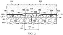
- FIGURES 1 and 2 presented is an illustrative, non-limiting example embodiment of a treatment system 100 for treating a tissue site 102, such as an incision 104.
- the incision 104 is shown extending through or involving epidermis 106, dermis 108, and subcutaneous tissue 110.
- the treatment system 100 may also be used with other tissue sites, and may be utilized with or without reduced pressure as described herein.
- the treatment system 100 may include a dressing assembly 112 having a dressing bolster 114, which may be referred to as a manifold member 114.
- some embodiments of the treatment system 100 may include a sealing member 116 and a reduced-pressure subsystem 118.
- Some embodiments of the treatment system 100 may also include a reduced-pressure indicator 101. While the treatment system 100 is shown in the context of a reduced-pressure dressing over an incision 104, the treatment system 100 may be used on other tissue sites, including open wounds. Further, features may be optionally added to or omitted from the treatment system 100 to suit different therapeutic applications, scenarios, or preferences, and thus, features described herein are not to be considered essential unless explicitly stated.
- the dressing bolster 114 may include a first side 120 and a second side 122 positioned opposite or facing opposite to the first side 120.
- the first side 120 of the dressing bolster 114 may be configured to face outward from or away from the tissue site 102, and the second side 122 of the dressing bolster 114 may be configured to face inward or toward the tissue site 102.
- the second side 122 of the dressing bolster 114 may also be referred to as a second, inward-facing side 122.
- the dressing bolster 114 may be formed from any bolster material or manifold material that provides a vacuum space, or treatment space. Reduced pressure applied to the dressing bolster 114 may enhance the permeability of the dressing bolster 114.
- the dressing bolster 114 may be formed from a porous and permeable foam or foam-like material, a member formed with pathways, a graft, a gauze, or any combination thereof.
- the dressing bolster 114 may be a reticulated, open-cell polyurethane or polyether foam that may be fluid permeable.
- a suitable foam material may be a GRANUFOAM TM material available from Kinetic Concepts, Inc. (KCI) of San Antonio, Texas.
- manifold may refer to a substance or structure that may assist in applying reduced pressure to, delivering fluids to, or removing fluids from a tissue site.
- a manifold may include a plurality of flow channels or pathways. The plurality of flow channels may be interconnected to improve distribution of fluids provided to and removed from an area of tissue around the manifold.
- manifolds may include, without limitation, devices that have structural elements arranged to form flow channels, cellular foam, such as open-cell foam, porous tissue collections, and liquids, gels, and foams that include or cure to include flow channels.
- the reticulated pores of the GRANUFOAM TM material may be helpful in carrying out the manifold function, but as stated above, other materials may be utilized.
- a material with a higher or lower density than the GRANUFOAM TM material may be desirable in some embodiments. This material may have, for example, a smaller pore size than the GRANUFOAM TM material.
- the following may be used without limitation: GRANUFOAM TM material, FXI technical foam, gauze, a flexible channel-containing member, a graft, and other similar materials.
- ionic silver may be added to the material, such as, for example, by a micro bonding process.
- Other substances, such as antimicrobial agents may also be added to the material.
- a comfort layer 124 may be coupled, for example, by a heat bond 130 or other suitable technique to the second, inward-facing side 122 of the dressing bolster 114.
- the comfort layer 124 may include a first side 126 and a second side 128 positioned opposite or facing opposite to the first side 126.
- the first side 126 of the comfort layer 124 may be configured to face outward from or away from the tissue site 102, and the second side 128 of the comfort layer 124 may be configured to face inward or toward the tissue site 102.
- the first side 126 of the comfort layer 124 may be coupled to the second side 122 of the dressing bolster 114.
- the comfort layer 124 may also be referred to as an interfacial layer, a tissue interface layer, or tissue contact layer.
- the second side 128 of the comfort layer 124 may also be referred to as a second, inward-facing side 128.
- the comfort layer 124 may enhance patient comfort when the dressing bolster 114 is adjacent to or in contact with the epidermis 106 of a patient.
- the comfort layer 124 may be any material that helps prevent skin irritation and discomfort while allowing fluid transmission through the comfort layer 124.
- the comfort layer 124 may include or be formed of a woven material, an elastic material, a polyester knit textile substrate, a non-woven material, or a fenestrated film.
- an INTERDRY TM textile material available from Milliken Chemical, a division of Milliken & Company, Inc. of Spartanburg, South Carolina, may be utilized.
- the comfort layer 124 may include antimicrobial substances, such as silver.
- the dressing bolster 114 may include a plurality of flexibility notches or recesses, analogous to notches 218 shown in FIGURE 4 , for example, that may be lateral cuts in the dressing bolster 114 on the first side 120.
- the dressing bolster 114 may additionally or alternatively include one or more longitudinal cuts or notches, which may intersect the lateral cuts or notches.
- the flexibility notches may enhance the flexibility of the dressing bolster 114. The enhanced flexibility may be particularly useful when the dressing assembly 112 is applied over a joint or other area of movement on a patient.
- the flexibility notches may also take various shapes without limitation, such as, for example, hexagons, slits, or squares.
- the dressing bolster 114 may include lateral edges (not shown) that are orthogonal relative to the second, inward-facing side 122 of the dressing bolster 114.
- the lateral edges of the dressing bolster 114 may be analogous to lateral edges 205 of dressing bolster 204 depicted in FIGURE 4 .
- the lateral edges of the dressing bolster 114 may also have a beveled edge or angled edge. The angled or beveled edge may help distribute shear stress between the dressing bolster 114 and the epidermis 106 of a patient.
- the lateral edges of the dressing bolster 114 may substantially correspond to lateral edges (not shown) of the comfort layer 124.
- the sealing member 116 may provide a fluid seal over the dressing bolster 114 and a portion of the epidermis 106 of the patient.
- the sealing member 116 may be formed from any material that allows for a fluid seal.
- the terms "fluid seal,” or “seal,” may be a seal adequate to maintain reduced pressure at a desired site given the particular reduced-pressure source or subsystem involved.
- the sealing member 116 may be sealed against the epidermis 106, or against a gasket or drape, by a sealing apparatus, such as, for example, a pressure-sensitive adhesive.
- the sealing apparatus may take numerous forms, such as an adhesive sealing tape, drape tape, or strip; double-sided drape tape; pressure-sensitive adhesive; paste; hydrocolloid; hydrogel; or other suitable sealing device. If a tape is used, the tape may be formed of the same material as the sealing member 116 with a pre-applied, pressure-sensitive adhesive.
- the pressure-sensitive adhesive may be applied on a side of the sealing member 116 adapted to face the epidermis 106, such as an inward-facing side of the sealing member 116.
- the pressure-sensitive adhesive may provide a fluid seal between the sealing member 116 and the epidermis, and may be utilized in combination with a gasket or drape against the epidermis 106. Before the sealing member 116 is secured to the epidermis 106, removable strips or release liners that cover the pressure-sensitive adhesive may be removed.
- the sealing member 116 may be an elastomeric material configured to provide a fluid seal.
- "Elastomeric” may refer to a material having the properties of an elastomer, such as a polymeric material that has rubber-like properties. Some elastomers may have ultimate elongations greater than 100% and a significant amount of resilience. The resilience of a material may refer to the ability of the material to recover from an elastic deformation.
- elastomers may include, without limitation, natural rubbers, polyisoprene, styrene butadiene rubber, chloroprene rubber, polybutadiene, nitrile rubber, butyl rubber, ethylene propylene rubber, ethylene propylene diene monomer, chlorosulfonated polyethylene, polysulfide rubber, polyurethane, EVA film, co-polyester, and silicones.
- sealing member materials may include a silicone drape, a TEGADERM TM drape available from 3M, an acrylic drape, such as one available from Avery Dennison, or an incise drape.
- the sealing member 116 may be comprised of a material including a high moisture vapor transmission rate (MVTR).
- MVTR moisture vapor transmission rate
- the use of a high MVTR material for the sealing member 116 may permit moisture vapor to pass through the sealing member 116, external to the dressing assembly 112, while maintaining the fluid seal described herein.
- the sealing member 116 may include a first sealing member portion 132 and a second sealing member portion 134.
- the first sealing member portion 132 may extend over or cover the first side 120 of the dressing bolster 114.
- the sealing member 116 may extend further to form a sealing member flange, or sealing member extension 136, which has a first side (not shown) and a second, inward-facing side (not shown).
- the second, inward-facing side of the sealing member extension 136 may be adapted to face the epidermis 106.
- An aperture (not shown) may be formed on a portion of the sealing member 116 to allow fluid communication with a conduit interface 138, which may be part of a reduced-pressure assembly 140.
- the aperture on the sealing member 116 may be analogous to aperture 234 depicted in FIGURE 3 .
- the second, inward-facing side of the sealing member extension 136 may be placed on a first side (not shown) of the second sealing member portion 134, and coupled, such as by an adhesive, a bond 135, a weld (e.g., ultrasonic or RF welding), or by cements.
- the first side of the second sealing member portion 134 may face away or outward from the epidermis 106.
- the second sealing member 134 may be positioned on and extend outward from the second side 122 of the dressing bolster 114 and be coupled to a portion of the first sealing member 132 as described. Further, in some examples, the first sealing member portion 132 and the second sealing member portion 134 may be integrally formed with one another.
- first sealing member portion 132 may include a plurality of bellows 142, folds, or stretch zones.
- the bellows 142 may provide additional drape material when needed to respond to stretching or other movement. For example, if the dressing assembly 112 is used on a joint, when the joint is flexed, the bellows 142 may provide additional drape material to facilitate such movement.
- one or more release members may be releasably coupled to the first side of the second sealing member portion 134.
- the release members may be analogous to release members 242 depicted in FIGURE 5 , and may provide stiffness to assist with, for example, deployment of the dressing assembly 112.
- the release members may be, for example, casting paper or a film held on the first side of the second sealing member portion 134.
- Each release member may have a release agent disposed on a side of the release member configured to contact a component of the dressing assembly 112, such as the second sealing member portion 134, or other components described herein.
- the release agent may be a silicone coating and may have a release factor between about 5 grams per centimeter to about 15 grams per centimeter. In some embodiments, the release factor may be between about 2 grams per centimeter to about 6 grams per centimeter.
- the release agent may facilitate removal of the release member by hand and without damaging or deforming the dressing assembly 112.
- Release members suitable for use with the embodiments described herein may be, for example and without limitation, polyester release members specified as FRA 301(T-36) and FRA 396-T13, available from Fox River Associates, LLC of Geneva, Illinois.
- the polyester release members may be a polyethylene terephthalate (PET) release member as described herein.
- PET polyethylene terephthalate
- the release members may have a film thickness between about 30 microns to about 70 microns. In some embodiments, the film thickness may be between about 47 microns to about 53 microns.
- the release members may have a tensile break strength in a machine direction between about 9 kilograms per square millimeter to about 15 kilograms per square millimeter.
- the release members may have a tensile break strength between about 15 kilograms per square millimeter to about 23 kilograms per square millimeter.
- the elongation at break of the release members in both the machine direction and the transverse direction may be between about 40 percent to about 140 percent.
- the release members may have a shrinkage in the machine direction between about 0.0 percent to about 2.5 percent, and a shrinkage in the transverse direction between about 0.0 percent to about 1.2 percent.
- the reduced-pressure subsystem 118 may include a reduced-pressure source 144.
- the reduced-pressure source 144 may provide reduced pressure as a part of the treatment system 100.
- the reduced-pressure source 144 may be configured to be coupled in fluid communication with the dressing assembly 112.
- the reduced-pressure source 144 may be fluidly coupled to the conduit interface 138 by a delivery conduit 148.
- the term "reduced pressure” may refer to a pressure less than the ambient pressure at a tissue site being subjected to treatment, such as the tissue site 102.
- the reduced pressure may be less than the atmospheric pressure.
- the reduced pressure may also be less than a hydrostatic pressure at a tissue site. Unless otherwise indicated, quantitative values of pressure stated herein are gauge pressures.
- the reduced pressure delivered to the dressing bolster 114 may be constant or varied, patterned or random, and may be delivered continuously or intermittently.
- vacuum and “negative pressure” may be used to describe the pressure applied to a tissue site, the actual pressure applied to the tissue site may be more than the pressure normally associated with a complete vacuum. Consistent with the use herein, unless otherwise indicated, an increase in reduced pressure or vacuum pressure may refer to a relative reduction in absolute pressure.
- the reduced-pressure source 144 is shown as having a reservoir region 146, or canister region.
- An interposed membrane filter (not shown), such as hydrophobic or oleophobic filter, may be interspersed between the reduced-pressure delivery conduit 148 and the reduced-pressure source 144.
- One or more devices such as a representative device 150, may be fluidly coupled to the reduced-pressure delivery conduit 148.
- the representative device 150 may be, for example, another fluid reservoir, a collection member to hold exudates and other fluids removed, a pressure-feedback device, a volume detection system, a blood detection system, an infection detection system, a flow monitoring system, or a temperature monitoring system. Multiple representative devices 150 may be included.
- One or more of the representative devices 150 may be formed integrally with the reduced-pressure source 144.
- the reduced-pressure source 144 may be any device for supplying a reduced pressure, such as a vacuum pump, wall suction, or other source. While the amount and nature of reduced pressure applied to a tissue site may vary according to the application, the reduced pressure may be, for example, between about -5 mm Hg (-667 Pa) to about -500 mm Hg (-66.7 kPa). In some embodiments, the reduced pressure may be between about -75 mm Hg (-9.9 kPa) to about -300 mm Hg (-39.9 kPa).
- the reduced pressure developed by the reduced-pressure source 144 may be delivered through the delivery conduit 148 to the conduit interface 138.
- the conduit interface 138 may allow the reduced pressure to be delivered through the sealing member 116 to the dressing bolster 114.
- the conduit interface 138 may provide fluid communication external to the sealing member 116 without the application of reduced pressure.
- the reduced-pressure indicator 101 may be configured to indicate that a reduced pressure of at least of certain threshold level is being delivered to the tissue site 102.
- the reduced-pressure indicator 101 may be a separate unit fluidly coupled to the sealing member 116 such that reduced pressure from within the sealed space of the sealing member 116 reaches the reduced-pressure indicator 101.
- the reduced-pressure indicator 101 may be associated with the conduit interface 138 as a part of the reduced-pressure assembly 140. When adequate reduced pressure is present, the reduced-pressure indicator 101 may be configured to assume a collapsed position. When inadequate reduced pressure is present, the reduced-pressure indicator 101 may be configured to assume a non-collapsed position.
- the dressing assembly 112 may include a gasket member 117.
- the gasket member 117 may also be referred to interchangeably as an interface seal or sealing ring 117.
- features or characteristics of the gasket member 117 may apply to the sealing ring 117, and features or characteristics of the sealing ring 117 may apply to the gasket member 117.
- the gasket member 117 and the sealing ring 117 may be configured in any suitable shape to enhance or otherwise provide a fluid seal around the tissue site 102, such as the incision 104.
- the epidermis 106 may have recesses, cracks, wrinkles, or other discontinuities on a surface of the epidermis 106 that may cause leaks.
- folds, buckles, wrinkles, or other discontinuities may form in the sealing member 116 and cause leaks.
- the gasket member 117 and the sealing ring 117 may help seal any such skin or sealing member discontinuities around the tissue site 102.
- the gasket member 117 or the sealing ring 117 may be adapted to be positioned between the dressing assembly 112 and the epidermis 106 and/or the tissue site 102. In some examples, the gasket member 117 may be positioned on, coupled to, or directly coupled to the second side 122 of the dressing bolster 114 or the second side 128 of the comfort layer 124.
- the gasket member 117 or the sealing ring 117 may be formed, as an illustrative example, by applying or bonding a sealing material around a perimeter or circumference of a portion of the dressing assembly 112.
- sealing material of the gasket member 117 or the sealing ring 117 may be configured in the shape of a ring in some embodiments, other shapes are suitable, and may include, without limitation, circles, squares, rectangles, discontinuous shapes, continuous shapes, irregular shapes, linear shapes, other shapes or portions that overlap one another, or combinations thereof.
- the sealing material may include hydrocolloids, hydrogels, silicone polymers (both crosslinked and uncrosslinked gels), and natural gums (xanthan, guar, cellulose).
- the sealing material may include other soft polymer gels, such as, for example, those based on polyurethanes, polyolefin gels, and acrylics.
- the gasket member 117 or the sealing ring 117 may be deployed by hand or extruded from an applicator, such as a syringe, to form a ring or other shape prior to application of the dressing assembly 112 to the tissue site 102.
- Sealing materials suitable for application by extrusion may include, without limitation, water soluble gums such as xanthan, guar, or cellulose, and thick greases, such as silicones.
- the sealing ring 117 may be bonded in any suitable manner, such as, for example, by a heat bond, to the second, inward facing side 128 of the comfort layer 124 during manufacture of the dressing assembly 112. In at least this manner, the sealing ring 117 may be adapted to be positioned between the comfort layer 124 and the epidermis 106 and/or the tissue site 102.
- the gasket member 117 or the sealing ring 117 may include an absorbent.
- the sealing ring 117 may be a hydrocolloid comprising an absorbent, such as carboxy methyl cellulose (CMC).
- CMC carboxy methyl cellulose
- the absorbent may permit the sealing ring 117 to absorb fluid from the tissue site 102 in addition to enhancing the fluid seal around the tissue site 102.
- the sealing ring 117 including the absorbent may enhance the ability of the dressing assembly 112 to manage and direct fluid away from the tissue site 102 for keeping the tissue site 102 dry.
- the dressing bolster 114 may have a thickness between the first side 120 and the second, inward-facing side 122 of the dressing bolster 114.
- the thickness of the dressing bolster 114 may define at least a portion of a thickness of the dressing assembly 112.
- the sealing ring 117 may be adapted to be positioned between the dressing assembly 112 and the tissue site 102, as described above, and around or surrounding a circumference of the tissue site 102. Relative to the dressing assembly 112, the sealing ring 117 or the gasket member 117 may be positioned, for example, around, on, or at the lateral edges of the dressing bolster 114 and/or the comfort layer 124. Further, the sealing ring 117 or the gasket member 117 may extend beyond a lateral edge of the dressing bolster 114 and the comfort layer 124.
- the sealing ring 117 may be positioned around or surrounding a circumference of the dressing bolster 114 and/or the comfort layer 124. Further, the sealing ring 117 may be positioned around at least a portion of the dressing bolster 114 or the comfort layer 124 that is configured to be positioned directly against or in direct contact with the tissue site 102. At least a portion of the dressing bolster 114 and/or the comfort layer 124 may be exposed and configured to be positioned directly against the tissue site 102 when the sealing ring 117 is positioned on the dressing assembly 112. Further, in such embodiments, the sealing ring 117 may surround the exposed portion of the dressing bolster 114 and/or the comfort layer 124.
- the absorbent in the sealing ring 117 may wick or draw fluid in a lateral direction within the dressing assembly 112, normal to the thickness of the dressing bolster 114, and toward the lateral edges of the dressing bolster 114 for absorption in the sealing ring 117.
- fluid from the tissue site 102 may be wicked or otherwise drawn in a lateral direction along the surface of the tissue site 102 toward the lateral edges of the dressing bolster 114 and into the sealing ring 117.
- fluid from the tissue site 102 may also flow through the thickness of the dressing assembly 112 and the dressing bolster 114 at least by operation of the manifold material comprising the dressing bolster 114, described above.
- the dressing assembly 112 may include a longitudinal axis 151 configured to be positioned along a longitudinal or lengthwise dimension of the tissue site 102, such as the incision 104, a linear wound, or any wound or tissue site having a lengthwise or longitudinal dimension that is greater than its width.
- the treatment system 100 or the dressing assembly 112 may include a polymeric enhancement layer 153 configured to be positioned along or substantially aligned with the longitudinal axis 151 of the dressing assembly 112.
- the polymeric enhancement layer 153 may also be configured to be positioned along and in direct contact with a longitudinal or lengthwise dimension of the tissue site 102, such as the incision 104.
- the polymeric enhancement layer 153 may be positioned on a side of the dressing assembly 112 configured to face toward the tissue site 102 such that the polymeric enhancement layer 153 is configured to be positioned between the dressing assembly 112 and the tissue site 102.
- the polymeric enhancement layer 153 may be positioned on or coupled to the second side 128 of the comfort layer 124.
- the polymeric enhancement layer 153 may be positioned on or coupled to the second side 122 of the dressing bolster 114 with the comfort layer 124 omitted or positioned around the polymeric enhancement layer 153 such that the polymeric enhancement layer 153 is configured to directly contact the tissue site 102.
- the polymeric enhancement layer 153 may include a first side 156 a second side 158 positioned opposite or facing opposite to the first side 156.
- the first side 156 of the polymeric enhancement layer 153 may be coupled to the second side 128 of the comfort layer 124.
- the second side 158 of the polymeric enhancement layer 153 may be configured to directly contact the tissue site 102, such as the incision 104.
- at least a portion of the comfort layer 124 may be exposed around a periphery 160 of the polymeric enhancement layer 153 to form an exposed surface 162.
- the exposed surface 162 of the comfort layer 124 may be configured to be positioned directly against the tissue site 102.
- both the comfort layer 124 and the polymeric enhancement layer 153 may be configured to directly contact the tissue site 102. Further, the sealing ring 117 or the gasket member 117 may be positioned around the exposed surface 162 of the comfort layer 124. Although not shown, in some examples, the polymeric enhancement layer 153 may cover the second side 128 of the comfort layer 124 entirely.
- the polymeric enhancement layer 153 may include or be formed of at least one strip 164 of material that may be substantially aligned along the longitudinal axis 151 of the dressing assembly 112.
- the at least one strip 164 may have a length 161 and a width 163 perpendicular to the length 161.
- the length 161 may extend along the longitudinal axis 151 of the dressing assembly 112 between about 12.7 cm (5 inches) to about 25.4 cm (10 inches), and the width 163 may be between about 1.27 cm (0.5 inch) to about (5.08 cm (2 inches).
- the at least one strip 164 may include a plurality of strips 164.
- the second side 158 of the polymeric enhancement layer 153 may comprise an acrylic material, a silicone material, or both an acrylic and a silicone material configured to directly contact the tissue site 102, and more specifically, the incision 104.
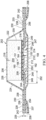
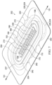
- FIGURES 3-5 depicted is a portion of an illustrative embodiment of a treatment system 200 suitable for treating, for example, a linear wound, area wound, a graft, or other wound.
- FIGURES 3-5 depict the treatment system 200 in a pre-deployment state.
- the treatment system 200 may include a dressing assembly 202, and the dressing assembly 202 may include a dressing bolster 204.
- the dressing bolster 204 has a first side 206 and a second, inward-facing side 208.
- the dressing bolster 204 may be formed from any suitable bolster material, or manifold material, as previously referenced in connection with the dressing bolster 114.
- a comfort layer 210 which has a first side 212 and a second, inward-facing side 214, may be coupled, such as, for example, by a heat bond 216 or other suitable technique to the second, inward-facing side 208 of the dressing bolster 204.
- the comfort layer 210 may be any material that helps prevent skin irritation and discomfort while allowing fluid transmission through the comfort layer 210. Suitable materials for the comfort layer 210 have been mentioned in connection with the comfort layer 124 of FIGURES 1-2 .
- the comfort layer 210 may include antimicrobial substances, such as silver. Further, in some embodiments, the comfort layer 210 may be made as a breathable, dry layer.
- the dressing bolster 204 may include a plurality of flexibility notches 218.
- the flexibility notches 218 may extend partially through or completely through the dressing bolster 204.
- the flexibility notches 218 may be lateral notches, or lateral cuts, in the dressing bolster 204.
- the flexibility notches 218 may also be one or more longitudinal notches, longitudinal cuts, or other cuts. The cuts may be made using a saw, a notched blade, a hot knife, or other device.
- the flexibility notches 218 may enhance the flexibility of the dressing bolster 204.
- the enhanced flexibility may be particularly useful when the dressing assembly 202 is applied over a joint or other area of movement on a patient. For example, if the dressing bolster 204 is used on a knee, the dressing bolster 204 may need to flex or extend as much as 100 % or more.
- the flexibility notches 218 may provide such flexibility.
- the dressing bolster 204 may have lateral edges 205 that are orthogonal with respect to the second, inward-facing side 208 of the dressing bolster 204.
- the lateral edges 205 may also have a shape, such as, for example, a beveled, angled, or rounded shape.
- the lateral edges 205 when angled, may be between about 10 degrees to about 90 degrees with respect to the second, inward-facing side 208 of the dressing bolster 204.
- the shaped lateral edges 205 may reduce shear stress between an epidermis of a patient and the dressing bolster 204. Other dimensions, steps, and processes may be used.
- the dressing bolster 204 may be manufactured from a foam block of GRANUFOAM TM material.
- the GRANUFOAM TM material may be, for example, a foam block having the dimensions of 1.21 meters x 1.8 meters x 0.5 meters.
- the foam block may be cut to have a 19 millimeter height, and a saw may be used to form lateral grooves, such as the flexibility notches 218, in the foam block.
- a dry layer, such as the comfort layer 210, may be laminated or otherwise attached to the second, inward facing side 208 of the dressing bolster 204.
- the foam block may be cut, for example, utilizing a die cutter to form a plurality of individual dressing bolsters 204.
- a sealing subsystem 222 may provide a fluid seal over the dressing assembly 202 and at least a portion of an epidermis of a patient.
- the sealing subsystem 222 may include a sealing member 224.
- the sealing member 224 may be formed with an upper drape portion or first sealing member portion 226 and a lower drape portion or second sealing member portion 228.
- the first sealing member portion 226 may extend over or cover the first side 206 of the dressing bolster 204 to form a drape flange, or drape extension 230.
- the drape extension 230 has a first side 232 and a second, inward-facing side 233.
- the second, inward-facing side 233 of the drape extension 230 may be adapted to face a tissue site of a patient as described above.
- An aperture 234 may be formed on the first sealing member portion 226.
- the aperture 234 may provide fluid communication with a conduit interface (not shown).
- the conduit interface may be analogous to the conduit interface 138 in FIGURE 1 .
- the second sealing member portion 228 may have a first side 236 and a second, inward-facing side 237 adapted to face a tissue site as described above.
- the second, inward-facing side 233 of the drape extension 230 may be placed on the first side 236 of the second sealing member portion 228, and may be coupled to the first side 236 by an attachment device 238.
- the attachment device 238 may be, for example, an adhesive, a bond, a weld (e.g., ultrasonic or RF weld), cements, stitching, staples, or other coupling device.
- the second sealing member portion 228 may include an attachment apparatus on the second, inward-facing side 237 as described below.
- the second sealing member portion 228 may also include a treatment area aperture 240, depicted in FIGURE 5 , that may be adapted to permit fluid communication through the second sealing member portion 228 and, for example, between a tissue site and the dressing bolster 204.
- the treatment area aperture 240 may also provide an opening for at least a portion of the dressing bolster 204, or the comfort layer 210, to be positioned directly against an epidermis and/or a tissue site of a patient.
- the first sealing member portion 226 may include a plurality of folds 220 or bellows to facilitate movement as described above.
- the folds 220 may allow the first sealing member portion 226 to expand.
- additional drape material from the folds 220 may be released to facilitate movement of the first sealing member portion 226.
- the folds 220 may also be formed as ridges having the cross-sectional shape of an accordion that provides additional drape material when flattened or stretched, for example.
- One or more release members 242 may be releasably coupled to the first side 236 of the second sealing member portion 228, such as, for example, with an adhesive (not shown) applied on at least a portion of the first side 236.
- the release members 242 may provide stiffness to the second sealing member portion 228, and may cover the adhesive or other attachment apparatus to provide a grasping surface during deployment of the dressing assembly 202.
- the release members 242 may be casting paper or a film held on the first side 236 of the second sealing member portion 228.
- the first side 236 of the second sealing member portion 228 may include an adhesive 244 adapted to retain the second side 208 of the dressing bolster 204 against the second sealing member portion 228 during assembly and usage.
- a center release member 246 may cover and protect the adhesive 244 prior to assembly.
- the release members 242 that may provide stiffness to the sealing member 224 during deployment may be positioned outboard of the adhesive 244 on the first side 236 of the second sealing member portion 228.
- the dressing assembly 202 may include a sealing ring 248.
- the sealing ring 248 may help seal any wrinkles or discontinuities in the epidermis or drape that might otherwise cause leaks.
- the sealing ring 248 may also be referred to interchangeably as an interface seal or a gasket member 248.
- features or characteristics of the gasket member 248 may apply to the sealing ring 248, and features or characteristics of the sealing ring 248 may apply to the gasket member 248.
- the previously described features of the sealing ring 117 or the gasket member 117 associated with the dressing assembly 112 may apply by analogy to the sealing ring 248 or the gasket member 248 associated with the dressing assembly 202.
- the sealing ring 248 or the gasket member 248 may be, for example, positioned to cover a portion of the second, inward-facing side 237 of the second sealing member portion 228.
- the sealing ring 248 or the gasket member 248 may be coupled directly to the dressing assembly 202, or coupled with an optional sealing-ring attachment device 249, such as an acrylic adhesive, cement, or other coupling device.
- the sealing ring 248 or the gasket member 248 may be coupled to the second inward-facing side 208 of the dressing bolster 204, and/or to an adjacent layer, such as the comfort layer 210.
- the sealing ring 248 or the gasket member 248 may straddle an edge of the dressing bolster 204, or otherwise extend beyond an edge of the dressing bolster 204, as depicted in FIGURE 4 .
- the sealing ring 248 or the gasket member 248 may be coupled to a portion of the sealing member 224, such as the first sealing member 226 and/or the second sealing member 228.
- the dressing bolster 204 may entirely overlap the sealing ring 248 or the gasket member 248 as suggested in FIGURE 11 . While reference is made to a "ring,” discrete members, including linear members, may make up the sealing ring 248 or the gasket member 248.
- the sealing ring 248 may comprise a sealing material, such as, for example, any of the sealing materials previously described in connection with the sealing ring 117, or other material that provides initial tack between the dressing assembly 202 and an epidermis of a patient. Further, the sealing ring 248 may have a durometer, such as a material softness or hardness, between about 20 Shore 00 to about 90 Shore OO. In some embodiments, the durometer of the sealing ring 248 may be between about 70 Shore 00 to about 80 Shore OO. The sealing ring 248 may have a modulus of elasticity that falls between the modulus of elasticity of the second sealing member portion 228 and the modulus of elasticity of a tissue site and/or epidermis of a patient.
- a sealing material such as, for example, any of the sealing materials previously described in connection with the sealing ring 117, or other material that provides initial tack between the dressing assembly 202 and an epidermis of a patient.
- the sealing ring 248 may have a
- the sealing ring 248 may have a thickness 250 and a width 252.
- the thickness 250 of the sealing ring 248 may be between about 0.3 millimeters to about 2.5 millimeters. In some embodiments, the thickness 250 may be between about 0.7 millimeters to about 1.25 millimeters.
- the width 252 of the sealing ring 248 may be between about 10 millimeters to about 30 millimeters. Other dimensions are possible. In some illustrative embodiments, the thickness 250 may be about 0.7 millimeters and the width 252 may be about 20 millimeters. Further, in some embodiments, the width 252 of the sealing ring 248 may extend beyond an edge of the dressing bolster 204 by about 10 millimeters and overlap the dressing bolster 204 by about 10 millimeters.
- the second sealing member portion 228 may have a thickness 229 between about 0.178 millimeters to about 0.254 millimeters, or about 7 mils to about 10 mils.
- the ratio of the sealing ring thickness 250 to the sealing member thickness 229 may be between about 2.75 to about 7.03.
- the sealing ring 248 may include fenestrations or apertures.
- the sealing ring 248 may comprise a patterned sealing material on the second, inward-facing side 214 of the comfort layer 210, or on the second, inward-facing side 208 of the dressing bolster 204.
- the pattern may be, for example, spaced islands, crossing lines of sealing material, or any other suitable pattern.
- the sealing ring 248 may function as a two-sided gasket that may provide a seal between the dressing assembly 202 and a tissue site and/or epidermis of a patient.
- the sealing ring 248 may provide a seal between the dressing bolster 204, the comfort layer 210, or the second sealing member portion 228 and a tissue site and/or epidermis of a patient.
- the sealing ring 248 may absorb perspiration or other fluids from a tissue site. Further, the sealing ring 248 may help distribute shear forces created, for example, by the application of reduced pressure at the interface of the dressing bolster 204 and a tissue site and/or epidermis of a patient.
- the dressing assembly 202 shown in FIGURES 4-5 may include the longitudinal axis 151 configured to be positioned along a longitudinal or lengthwise dimension of the tissue site 102, such as the incision 104, a linear wound, or any wound or tissue site having a lengthwise or longitudinal dimension that is greater than its width.
- the treatment system 200 or the dressing assembly 202 may include the polymeric enhancement layer 153 configured to be positioned along or substantially aligned with the longitudinal axis 151 of the dressing assembly 202.
- the polymeric enhancement layer 153 may also be configured to be positioned along and in direct contact with a longitudinal or lengthwise dimension of the tissue site 102, such as the incision 104.
- the polymeric enhancement layer 153 may be positioned on a side of the dressing assembly 202 configured to face toward the tissue site 102 such that the polymeric enhancement layer 153 is configured to be positioned between the dressing assembly 202 and the tissue site 102.
- the polymeric enhancement layer 153 may be positioned on or coupled to the second side 214 of the comfort layer 210.
- the polymeric enhancement layer 153 may be positioned on or coupled to the second side 208 of the dressing bolster 204 with the comfort layer 210 omitted or positioned around the polymeric enhancement layer 153 such that the polymeric enhancement layer 153 is configured to directly contact the tissue site 102.
- the first side 156 of the polymeric enhancement layer 153 may be coupled to the second side 214 of the comfort layer 210.
- the second side 158 of the polymeric enhancement layer 153 may be configured to directly contact the tissue site 102, such as the incision 104.
- the comfort layer 210 may be exposed around the periphery 160 of the polymeric enhancement layer 153 to form the exposed surface 162 such that both the comfort layer 210 and the polymeric enhancement layer 153 may be configured to directly contact the tissue site 102.
- the sealing ring 248 or the gasket member 248 may be positioned around the exposed surface 162 of the comfort layer 210.
- a portion of the second, inward-facing side 237 of the second sealing member portion 228 may be covered with a sealing apparatus or device 254, such as an adhesive.
- a sealing apparatus or device 254 such as an adhesive.
- the sealing device 254 when in the pre-deployment state, may be covered by a bottom release member 256 and side release members 258.
- the bottom release member 256 may cover and protect, for example, the sealing device 254 and the sealing ring 248.
- the side release members 258 may also cover and protect the sealing device 254. Similar to the release members 242, the side release members 258 may provide a grasping surface for a user to facilitate deployment of the dressing assembly 202.
- the release members 242, the bottom release member 256, and /or the side release members 258 may be comprised of a polar semi-crystalline polymer, such as, for example, polyethylene terephthalate (PET).
- PET polyethylene terephthalate
- Use of a polar semi-crystalline polymer for the release members 242, the bottom release member 256, and /or the side release members 258 may substantially preclude wrinkling or other deformation of the dressing assembly 202.
- any deformation of the release members 242, the bottom release member 256, and/or the side release members 258 may cause wrinkling or deformation of a component of the dressing assembly 202.
- the polar semi-crystalline polymer is highly orientated and resistant to softening, swelling, or other deformation that may occur when brought into contact with components of the dressing assembly 202, or when subjected to temperature or environmental variations, or sterilization.
- the polar semi-crystalline polymer may not deform when in contact with the compounding ingredients of the hydrocolloid.
- the release members 242, the bottom release member 256, and/or the side release members 258 may be configured to resist deformation when exposed to temperature variations between about 40 degrees Celsius to about 60 degrees Celsius, and gamma sterilization doses between about 25kGy to about 45 kGy.
- the bottom release member 256 may be removed to expose the sealing device 254 on the second, inward-facing side 237 of the second sealing member portion 228. Removal of the bottom release member 256 may also expose a second, inward-facing surface 247 of the sealing ring 248.
- the sealing device 254 and/or the second, inward-facing surface 247 of the sealing ring 248 may be placed against a portion of an epidermis of a patient and around a tissue site that may include a linear wound as described above.
- the side release members 258 may be removed after applying the second sealing member portion 228.
- the release members 242 on the first side 236 of the second sealing member portion 228 may be removed after applying the second sealing member portion 228.
- a conduit interface may be coupled to the aperture 234 in the first sealing member portion 226, and reduced pressure may be delivered to the dressing assembly 202.
- a press in applying and coupling a sealing member to a dressing bolster, may be utilized to remove any wrinkles in the sealing member. Further, the medical bolster material of the shaped dressing assembly may be cut using a die cutter, or by hand with a router.
- FIGURES 6A-6C depict the treatment system 300 assembled in stages at a tissue site, such as a linear wound 306.
- a closure device 302 such as, for example, stitches 304, close the linear wound 306.
- Other closure devices 302, such as epoxy or staples may be utilized to close the linear wound 306.
- the linear wound 306 may include a portion through an epidermis 308, dermis 310, and subcutaneous tissue 312 of a patient.
- a dressing assembly 314 may be disposed proximate to the linear wound 306.
- the dressing assembly 314 may include a dressing bolster 316.
- the dressing bolster 316 may be formed from the bolster or manifold materials previously mentioned.
- the dressing bolster 316 may include a plurality of lateral notches 318 and one or more longitudinal notches 320.
- the dressing bolster 316 has a first side 322 and a second, inward-facing side 324.
- the first side 322 may include an adhesive layer 323.
- the adhesive layer 323 may help secure a sealing member 340 thereto, as shown in FIGURE 6C .
- the dressing assembly 314 may include a comfort layer 326.
- the second, inward-facing side 324 of the dressing bolster 316 may be covered with the comfort layer 326.
- the comfort layer 326 has first side 328 and a second, inward-facing side 330.
- the first side 328 of the comfort layer 326 may be coupled by an attachment device 332, such as, for example, a heat bond, adhesive, weld, or other attachment device, to the second, inward-facing side 324 of the dressing bolster 316.
- the dressing assembly 314 may include a sealing ring 334.
- the sealing ring 334 may be coupled, at least in part, to the second, inward-facing side 330 of the comfort layer 326.
- the sealing ring 334 may be analogous to the sealing ring 117 of FIGURE 2 and the sealing ring 248 of FIGURES 3-5 . Further, the sealing ring 334 may be referred to interchangeably as a gasket member 334 analogous to the gasket member 117 and the gasket member 248.
- the sealing ring 334 may comprise any of the sealing materials previously described in connection with the sealing ring 117 and the sealing ring 248.
- the sealing ring 334 may adhere directly to the comfort layer 326, or may be coupled with a sealing-ring attachment device 336 to the comfort layer 326.
- the sealing-ring attachment device 336 may be, for example, acrylic adhesive, cement, or other suitable attachment device.
- the sealing ring 334 and/or the sealing ring attachment device 336 may be co-extensive with the comfort layer 326, or may extend beyond a lateral edge of the comfort layer 326 and the dressing bolster 316.
- the dressing assembly 314 may include the longitudinal axis 151 configured to be positioned along a longitudinal or lengthwise dimension of a tissue site, such as a linear wound 306, or any wound or tissue site having a lengthwise or longitudinal dimension that is greater than its width.
- the treatment system 300 or the dressing assembly 314 may include the polymeric enhancement layer 153 configured to be positioned along or substantially aligned with the longitudinal axis 151 of the dressing assembly 314.
- the polymeric enhancement layer 153 may also be configured to be positioned along and in direct contact with a longitudinal or lengthwise dimension of the linear wound 306.
- the polymeric enhancement layer 153 may be positioned on a side of the dressing assembly 314 configured to face toward the linear wound 306 such that the polymeric enhancement layer 153 is configured to be positioned between the dressing assembly 314 and the linear wound 306.
- the polymeric enhancement layer 153 may be positioned on or coupled to the second side 330 of the comfort layer 326.
- the polymeric enhancement layer 153 may be positioned on or coupled to the second side 324 of the dressing bolster 316 with the comfort layer 326 omitted or positioned around the polymeric enhancement layer 153 such that the polymeric enhancement layer 153 is configured to directly contact the linear wound 306.
- the first side 156 of the polymeric enhancement layer 153 may be coupled to the second side 330 of the comfort layer 326.
- the second side 158 of the polymeric enhancement layer 153 may be configured to directly contact a tissue site, such as the linear wound 306.
- the comfort layer 326 may be exposed around the periphery 160 of the polymeric enhancement layer 153 to form the exposed surface 162 such that the polymeric enhancement layer 153 may be configured to directly contact the linear wound 306, and the comfort layer 326 may be configured to directly contact a portion of the tissue site around the linear wound 306.
- the sealing ring 334 or the gasket member 334 may be positioned around the exposed surface 162 of the comfort layer 326.
- a second, inward-facing surface 338 of the sealing ring 334 may be covered by a release member or release liner (not shown).
- a release member or release liner (not shown) may also temporarily cover a portion of the sealing ring 334 and/or sealing ring attachment device 336 to provide a grasping surface during deployment of the dressing assembly 314.
- the release liner or release member covering, for example, the sealing ring 334, the sealing ring attachment device 336, and/or other components of the dressing assembly 314 may be analogous to the release members 242, 256, and 258 of FIGURES 3-5 .
- the release members may be positioned on the dressing assembly 314 analogous to the release members 242, 256, and 258.
- the release members on the dressing assembly 314 may be comprised of any of the materials previously described for the release members 242, 256, and 258, such as, for example, a polar semi-crystalline polymer or polyethylene terephthalate (PET).
- PET polyethylene terephthalate
- use of a polar semi-crystalline polymer such as PET as a release member on the dressing assembly 314 may substantially preclude deformation of the dressing assembly 314.
- the sealing ring 334 may be separately applied around the linear wound 306 before the dressing bolster 316 is applied thereto.
- a sealing member 340 may be disposed over the dressing assembly 314 and a portion of the epidermis 308 to form a sealed space 342 between the dressing assembly 314 and the linear wound 306.
- an aperture (not shown) may be formed or preformed in the sealing member 340.
- a conduit interface (not shown), analogous to conduit interface 138 described above, may be coupled to the sealing member 340 to provide fluid communication with the sealed space 342 through the aperture.
- a reduced-pressure source (not shown), analogous to the reduced-pressure source 144 in FIGURE 1 , may be coupled to the conduit interface to provide reduced pressure to the sealed space 342 to treat the linear wound 306.
- a delivery conduit (not shown), analogous to the delivery conduit 148 in FIGURE 1 , may be utilized for coupling the reduced pressure source to the conduit interface.
- Reduced pressure may be applied to the tissue site, such as the linear wound 306, and fluid may be extracted from the tissue site and into the dressing assembly 314.
- the fluid from the tissue site may be absorbed into the sealing ring 334.
- the fluid from the tissue site may be wicked or otherwise communicated in a lateral direction within the dressing assembly 314 toward the sealing ring 334.
- the polymeric enhancement layer 153 may include various example features.
- the polymeric enhancement layer 153 may include an exposed pattern of silicone material 166 and/or acrylic material 168.
- the silicone material 166, the acrylic material 168, or both the silicone material 166 and the acrylic material 168 may be configured to directly contact a tissue site.
- the acrylic material 168 may be an acrylic adhesive
- the silicone material 166 may be a silicone adhesive.
- the silicone material may be, without limitation, a silicone gel, a cured or completely cured silicone adhesive having minimal or no tack, and/or a multiple silicone gels including different hydrophilicity.
- the polymeric enhancement layer 153 may include a plurality of apertures 170 disposed through the polymeric enhancement layer 153 between the first side 156 and the second side 158 of the polymeric enhancement layer 153.
- the plurality of apertures 170 may be configured to be in fluid communication or to provide fluid communication between the second side 128, 214, 330 of the comfort layer 124, 210, 326 and a tissue site.
- the plurality of apertures 170 may be configured to be in fluid communication or to provide fluid communication between the second side 128, 214, 330 of the comfort layer 124, 210, 326 and the second side 158 of the polymeric enhancement layer 153.
- apertures 170 are illustrated as having a circular shape, other shapes and types of apertures may be suitable, such as, without limitation, slits, slots, fenestrations, holes, rectangular shapes, triangular shapes, linear shapes, square shapes, and others.
- the polymeric enhancement layer 153 may include a film layer 172 having a first side 174 and a second side 176 opposing or positioned opposite to the first side 174.
- suitable materials for the film layer 172 may be, without limitation, polyurethane and polyester.
- the acrylic material 168 or acrylic adhesive may be configured as an acrylic layer 178.
- the acrylic layer 178 may be positioned on the first side 174 of the film layer 172 and configured to be coupled to the second side 128, 214, 330 of the comfort layer 124, 210, 326.
- the silicone material 166 or silicone adhesive may be configured as a silicone layer 180.
- the silicone layer 180 may be positioned on the second side 176 of the film layer 172 and configured to be positioned in direct contact with a tissue site, such as the tissue site 102 or the linear wound 306.
- the acrylic layer 178 may form at least a portion of the first side 156 of the polymeric enhancement layer 153
- the silicone layer 180 may form at least a portion of the second side 158 of the polymeric enhancement layer 153.
- the plurality of apertures 170 may be disposed through the film layer 172, the acrylic layer 178, and the silicone layer 180 from the first side 156 to the second side 158 of the polymeric enhancement layer 153.
- a portion of the acrylic material 168 on the first side 156 of the polymeric enhancement layer 153 may be exposed on the second side 158 of the polymeric enhancement layer 153 through at least one of the apertures 170 and configured to be in direct contact with a tissue site, such as the tissue site 102 or the linear wound 306.
- a tissue site such as the tissue site 102 or the linear wound 306.
- the acrylic material 168 may be exposed through the silicone material 166 in some examples, the configuration may be reversed in other examples such that the silicone material 166 is exposed through the acrylic material 168 in an analogous manner. In other example embodiments, the acrylic material 168 may not be exposed.
- the acrylic material 168 may only be configured to couple the first side 156 of the polymeric enhancement layer 153 to the second side 128, 214, 330 of the comfort layer 124, 210, 326.
- the apertures 170 may remain open without the acrylic material 168 being exposed through the apertures 170.
- the film layer 172 may be omitted.
- the silicone layer 180 may include the plurality of apertures 170 disposed through the silicone layer 180, and the acrylic layer 178 may be positioned between the second side 128, 214, 330 of the comfort layer 124, 210, 326 and the silicone layer 180.
- a portion of the acrylic layer 178 may be exposed through the apertures 170 in the silicone layer 180 such that a portion of both the acrylic layer 178 and the silicone layer 180 may form the second side 158 of the polymeric enhancement layer 153 that is configured to be in direct contact with a tissue site.
- the acrylic layer 178 may not be exposed through the apertures 170, and instead, may only be configured to secure or couple the silicone layer 180 to the second side 128, 214, 330 of the comfort layer 124, 210, 326 such that only the silicone layer 180 forms the second side 158 of the polymeric enhancement layer 153.
- the exposed pattern on the second side 158 of the polymeric enhancement layer 153 may be dots of the acrylic material 168 without the silicone material 166, dots of the silicone material 166 without the acrylic material 168, or dots of both the acrylic material 168 and the silicone material 166 applied to a substrate material.
- the first side 174 of the film layer 172 may be configured to be coupled to the second side 128, 214, 330 of the comfort layer 124, 210, 326, and one or both of the silicone material 166 and the acrylic material 168 may be positioned on the second side 176 of the film layer 172 and configured to face a tissue site, such as the tissue site 102 or the linear wound 306.
- FIGURES 9A-9D illustrate additional example configurations for the polymeric enhancement layer 153.
- the polymeric enhancement layer 153 may be a polymeric enhancement layer 153a.
- the polymeric enhancement layer 153a may include the silicone material 166 formed into the strip 164.
- the polymeric enhancement layer 153 may be a polymeric enhancement layer 153b.
- the polymeric enhancement layer 153b may include alternating horizontal rows of the silicone material 166 and the acrylic material 168 formed into the strip 164.
- the polymeric enhancement layer 153 may be a polymeric enhancement layer 153c.
- the polymeric enhancement layer 153c may include alternating vertical rows of the silicone material 166 and the acrylic material 168 formed into the strip 164.
- the polymeric enhancement layer 153 may be a polymeric enhancement layer 153d.
- the polymeric enhancement layer 153d may include an alternating zig-zag pattern of the silicone material 166 and the acrylic material 168 formed into the strip 164.
- a method for treating a tissue site may include disposing a dressing assembly according to this disclosure proximate to a tissue site.
- the dressing assembly may include a dressing bolster, a comfort layer coupled to the dressing bolster, and a polymeric enhancement layer coupled to the comfort layer.
- the method may include covering the dressing assembly with a sealing member to form a sealed space between the dressing assembly and the tissue site.
- the method may include extracting fluid from the tissue site into the dressing assembly.
- the method may include exposing the tissue site to the silicone material 166 or the acrylic material 168 or both the silicone material 166 and the acrylic material 168 associated with the various embodiments of the polymeric enhancement layer 153 described herein.
- the dressing assembly 314 may be cut to accommodate different sizes of linear wounds 306 prior to being disposed on the linear wound 306 and covered with the sealing member 340.
- more than one dressing assembly 314 may be used.
- a first longitudinal end 344 of a first dressing assembly 346 may be cut to have a flat surface.
- a first longitudinal end 348 of a second dressing assembly 350 may be cut or otherwise formed with a flat surface.
- the first longitudinal end 344 of the first dressing assembly 346 may be placed proximate to and abutting the first longitudinal end 348 of the second dressing assembly 350.
- the sealing rings (not shown but analogous to sealing ring 334) below the first dressing assembly 346 and the second dressing assembly 350 may coalesce or combine to form an integral sealing ring or gasket member.
- a first longitudinal end 352 of a third dressing assembly 354 may be placed proximate to and abutting a lateral end or edge 356 of the second dressing assembly 350.
- the dressing assemblies 346, 350, 354 may be covered with a sealing member (not shown but analogous to sealing member 340 in FIG. 6C ) to form a sealed space that contains the dressing assemblies 346, 350, 354. Reduced pressure may be then be applied to the sealed space to treat the linear wound or wounds.
- the dressing assembly 400 may be used with treatment systems as described above, such as the treatment system 200.
- the dressing assembly 400 may include a dressing bolster 402.
- the dressing bolster 402 has a first side 404, a second, inward-facing side 406, and lateral edges 408.
- the lateral edges 408 may take any shape, but are shown formed with approximately a 45 degree angle with respect to the second, inward-facing side 406.
- a longitudinal notch 410 is visible.
- lateral notches may be included on the first side 404, and notches (not shown) may be added to the lateral edges 408.
- the longitudinal notch 410 and any other notches help provide flexibility to the dressing assembly 400.
- a comfort layer 412 may be coupled by an attachment device 414 to the second, inward-facing side 406 of the dressing bolster 402.
- a sealing ring 416 may be coupled to the comfort layer 412.
- the sealing ring 416 may be formed from the sealing materials previously mentioned.
- the sealing ring 416 may be coupled directly to the comfort layer 412, or may be attached to the comfort layer 412 by an attachment device, such as an acrylic adhesive (not shown).
- the dressing assembly 400 may be placed over and about a linear wound and then covered with a sealing member to form a sealed space. Reduced pressure may then be delivered to the sealed space to treat the linear wound.
- FIGURE 12 depicted is a cross-section of another embodiment of a dressing assembly 500.
- the dressing assembly 500 may be analogous to the dressing assembly 400 of FIGURE 11 .
- the dressing assembly 500 includes a dressing bolster 502 having a first side 504 and a second, inward-facing side 506.
- the lateral edges 508 are substantially orthogonal to the second, inward-facing side 506.
- the lateral edges 508 of the dressing bolster 502 may have any angle or shape.
- a sealing ring 514 may be laminated or coupled to a drape ring 510.
- the drape ring 510 may assist with positioning and manipulating the sealing ring 514 during assembly.
- the drape ring 510 may be coupled by an attachment device 512 to the second, inward-facing side 506 of the dressing bolster 502, or to an inward-facing side of a comfort layer 516.
- the sealing ring 514 may be covered by a release liner 518 prior to use.
- an attachment device such as an adhesive, may be applied to the second, inward-facing side of a sealing ring to provide tackiness or enhanced tackiness between the sealing ring and an epidermis of a patient.
- the attachment device may be particularly beneficial when the sealing ring comprises a harder hydrocolloid than those previously mentioned, or when applied in cold conditions to provide time for the sealing material to warm up and become adequately tacky.
Landscapes
- Health & Medical Sciences (AREA)
- Public Health (AREA)
- Engineering & Computer Science (AREA)
- Veterinary Medicine (AREA)
- Life Sciences & Earth Sciences (AREA)
- Animal Behavior & Ethology (AREA)
- General Health & Medical Sciences (AREA)
- Heart & Thoracic Surgery (AREA)
- Vascular Medicine (AREA)
- Biomedical Technology (AREA)
- Hematology (AREA)
- Chemical & Material Sciences (AREA)
- Materials Engineering (AREA)
- Epidemiology (AREA)
- Dermatology (AREA)
- Anesthesiology (AREA)
- Dispersion Chemistry (AREA)
- Materials For Medical Uses (AREA)
- Surgical Instruments (AREA)
Description
- This disclosure relates generally to medical treatment systems and, more particularly, but not by way of limitation, to absorbent dressings and systems for treating a tissue site with reduced pressure.
- Clinical studies and practice have shown that reducing pressure in proximity to a tissue site can augment and accelerate growth of new tissue at the tissue site. The applications of this phenomenon are numerous, but have proven particularly advantageous for treating wounds. Regardless of the etiology of a wound, whether trauma, surgery, or another cause, proper care of a wound is important to the outcome. Treatment of wounds or other tissue with reduced pressure may be commonly referred to as "negative-pressure therapy," but is also known by other names, including "negative-pressure wound therapy," "reduced-pressure therapy," "vacuum therapy," and "vacuumassisted closure," for example. Negative-pressure therapy may provide a number of benefits, including migration of epithelial and subcutaneous tissues, improved blood flow, and microdeformation of tissue at a wound site. Together, these benefits can increase development of granulation tissue and reduce healing times.
-
US 2018/353336 A1 concerns composite dressings for improved granulation and reduced maceration with negative-pressure treatment.WO 2018/227144 A1 concerns negative-pressure therapy with oxygen.WO 2017/040045 A1 concerns a dressing with increased apposition force. - While the clinical benefits of negative-pressure therapy are widely known, the cost and complexity of negative-pressure therapy can be a limiting factor in its application, and the development and operation of negative-pressure systems, components, and processes continues to present significant challenges to manufacturers, healthcare providers, and patients.
- Shortcomings with certain aspects of tissue treatment dressings, systems, and methods are addressed as shown and described in a variety of illustrative, non-limiting example embodiments herein. The invention provides a system for treating a tissue site according to claim 1. Further preferred optional features are provided in the dependent claims.
- In some example embodiments, a system for treating a tissue site may include a dressing assembly and a reduced-pressure source. The dressing assembly may include a dressing bolster, a comfort layer, a first sealing member, a second sealing member, a gasket member, and polymeric enhancement layer. The dressing bolster may have a first side and an opposing second side. The comfort layer may have a first side and an opposing second side. The first side of the comfort layer may be coupled to the second side of the dressing bolster. The first sealing member may cover the first side of the dressing bolster. The second sealing member may be positioned on and extend outward from the second side of the dressing bolster and be coupled to a portion of the first sealing member. The gasket member may be positioned on the second side of the dressing bolster. The polymeric enhancement layer may have a first side and an opposing second side. The first side of the polymeric enhancement layer may be coupled to the second side of the comfort layer. The second side of the polymeric enhancement layer may be configured to directly contact the tissue site. The reduced-pressure source may be configured to be coupled in fluid communication with the dressing assembly.
- In some example embodiments, a system for treating a tissue site may include a dressing assembly, a sealing member, and a reduced-pressure source. The dressing assembly may include a dressing bolster, a comfort layer, and a polymeric enhancement layer. The dressing bolster have a first side and a second side. The comfort layer may have a first side and a second side. The first side of the comfort layer may be coupled to the second side of the dressing bolster. The polymeric enhancement layer may have a first side and an opposing second side. The first side of the polymeric enhancement layer may be coupled to the second side of the comfort layer. The second side of the polymeric enhancement layer may be configured to directly contact the tissue site. The sealing member may be configured to cover the dressing assembly and to create a sealed space between the dressing assembly and the tissue site. The reduced-pressure source may be configured to be coupled in fluid communication with the sealed space.
- In some example embodiments, a dressing assembly may include a dressing bolster, a comfort layer, and a polymeric enhancement layer. The dressing bolster may include foam and may have a first side and a second side. The comfort layer may have a first side and a second side. The first side of the comfort layer may be coupled to the second side of the dressing bolster. The polymeric enhancement layer may have a first side and an opposing second side. The first side of the polymeric enhancement layer may be coupled to the second side of the comfort layer. The second side of the polymeric enhancement layer may be configured to directly contact the tissue site.
- In some example embodiments, a method for treating a tissue site may include disposing a dressing assembly proximate to the tissue site. The dressing assembly may include a dressing bolster, a comfort layer coupled to the dressing bolster, and a polymeric enhancement layer coupled to the comfort layer. Further, the method may include covering the dressing assembly with a sealing member to form a sealed space between the dressing assembly and the tissue site. Further, the method may include extracting fluid from the tissue site into the dressing assembly. Further, the method may include exposing the tissue site to a silicone material or an acrylic material or both a silicone material and an acrylic material associated with the polymeric enhancement layer.
- In some example embodiments, a system for treating a tissue site may include a dressing assembly. The dressing assembly may be configured to be coupled to a reduced pressure source and may include a dressing bolster, a comfort layer, a sealing member, and a polymeric layer. The dressing bolster may have a first side and an opposing second side. The comfort layer may have a first side and an opposing second side. The first side of the comfort layer may be positioned on the second side of the dressing bolster. The sealing member may be configured to cover the first side of the dressing bolster. The polymeric layer may include silicone and may have a first side and an opposing second side. The first side of the polymeric layer may be coupled to the second side of the comfort layer. The second side of the polymeric layer may be configured to directly contact the tissue site. Further, the polymeric layer may include a plurality of apertures disposed through the polymeric layer between the first side and the second side of the polymeric layer.
- In further examples, the polymeric layer may be substantially aligned along a longitudinal axis of the dressing assembly and configured to be positioned along a length of an incision at the tissue site. In further examples, the plurality of apertures through the polymeric layer may be substantially aligned along a longitudinal axis of the dressing assembly and configured to be positioned along a length of an incision at the tissue site. At least one of the plurality of apertures may include a diameter between about 2 millimeters to about 10 millimeters.
- In further examples, the plurality of apertures through the polymeric layer may be positioned in at least one longitudinal row along the longitudinal axis of the dressing assembly. In further examples, the at least one longitudinal row of apertures may include a first longitudinal row of apertures and a second longitudinal row of apertures, and the first longitudinal row of apertures may be offset from the second longitudinal row of apertures.
- In further examples, the second side of the comfort layer may have a first area and the second side of the polymeric layer may have a second area, and the first area may be larger than the second area. In further examples, the second area may be less than 30 percent of the first area. In further examples, at least a portion of the first area of the comfort layer and the second area of the polymeric layer are both configured to directly contact the tissue site.
- Other features and advantages of the illustrative example embodiments will become apparent with reference to the drawings and detailed description that follow.
-
-
FIGURE 1 is a perspective view of an illustrative example embodiment of a system for treating a tissue site; -
FIGURE 2 is a cross-section of a portion of an illustrative example embodiment of a dressing assembly depicted inFIGURE 1 , taken along line 2-2; -
FIGURE 3 is a perspective view of an illustrative example embodiment of a portion of a treatment system for treating a tissue site; -
FIGURE 4 is a cross-section of an illustrative example embodiment of a dressing assembly depicted inFIGURE 3 , taken along line 4-4; -
FIGURE 5 is an exploded, perspective view of the example dressing assembly ofFIGURE 4 in a state prior to assembly or deployment at a tissue site; -
FIGURES 6A-6C are perspective views, with a portion shown in cross-section, of a portion of an illustrative example embodiment of a treatment system being deployed over a linear wound; -
FIGURE 7 is a perspective view of a bottom surface of an illustrative example embodiment of a dressing assembly; -
FIGURE 8 is a perspective, exploded view of an illustrative example embodiment of a polymeric enhancement layer depicted inFIGURE 7 ; -
FIGURES 9A-9D are plan views of multiple illustrative example embodiments of polymeric enhancement layers suitable for use with a dressing assembly and system according to this disclosure; -
FIGURE 10 is a plan view of a portion of an illustrative example embodiment of a treatment system for treating a tissue site; -
FIGURE 11 is a cross-section of another illustrative example embodiment of a dressing assembly; and -
FIGURE 12 is a cross-section of yet another illustrative example embodiment of a dressing assembly. - The following description of example embodiments enables a person skilled in the art to make and use the subject matter set forth in the appended claims. Certain details already known in the art may be omitted. Further, the following detailed description is illustrative and non-limiting.
- Referring primarily to
FIGURES 1 and2 , presented is an illustrative, non-limiting example embodiment of atreatment system 100 for treating atissue site 102, such as anincision 104. Theincision 104 is shown extending through or involvingepidermis 106,dermis 108, andsubcutaneous tissue 110. Thetreatment system 100 may also be used with other tissue sites, and may be utilized with or without reduced pressure as described herein. - In some embodiments, the
treatment system 100 may include adressing assembly 112 having a dressing bolster 114, which may be referred to as amanifold member 114. In addition, some embodiments of thetreatment system 100 may include a sealingmember 116 and a reduced-pressure subsystem 118. Some embodiments of thetreatment system 100 may also include a reduced-pressure indicator 101. While thetreatment system 100 is shown in the context of a reduced-pressure dressing over anincision 104, thetreatment system 100 may be used on other tissue sites, including open wounds. Further, features may be optionally added to or omitted from thetreatment system 100 to suit different therapeutic applications, scenarios, or preferences, and thus, features described herein are not to be considered essential unless explicitly stated. - In some embodiments, the dressing bolster 114 may include a
first side 120 and asecond side 122 positioned opposite or facing opposite to thefirst side 120. Thefirst side 120 of the dressing bolster 114 may be configured to face outward from or away from thetissue site 102, and thesecond side 122 of the dressing bolster 114 may be configured to face inward or toward thetissue site 102. Thesecond side 122 of the dressing bolster 114 may also be referred to as a second, inward-facingside 122. - The dressing bolster 114 may be formed from any bolster material or manifold material that provides a vacuum space, or treatment space. Reduced pressure applied to the dressing bolster 114 may enhance the permeability of the dressing bolster 114. For example, the dressing bolster 114 may be formed from a porous and permeable foam or foam-like material, a member formed with pathways, a graft, a gauze, or any combination thereof. In some embodiments, the dressing bolster 114 may be a reticulated, open-cell polyurethane or polyether foam that may be fluid permeable. One example of a suitable foam material may be a GRANUFOAM™ material available from Kinetic Concepts, Inc. (KCI) of San Antonio, Texas.
- The term "manifold" as used herein may refer to a substance or structure that may assist in applying reduced pressure to, delivering fluids to, or removing fluids from a tissue site. A manifold may include a plurality of flow channels or pathways. The plurality of flow channels may be interconnected to improve distribution of fluids provided to and removed from an area of tissue around the manifold. Examples of manifolds may include, without limitation, devices that have structural elements arranged to form flow channels, cellular foam, such as open-cell foam, porous tissue collections, and liquids, gels, and foams that include or cure to include flow channels.
- The reticulated pores of the GRANUFOAM™ material may be helpful in carrying out the manifold function, but as stated above, other materials may be utilized. A material with a higher or lower density than the GRANUFOAM™ material may be desirable in some embodiments. This material may have, for example, a smaller pore size than the GRANUFOAM™ material. Among the many possible materials, the following may be used without limitation: GRANUFOAM™ material, FXI technical foam, gauze, a flexible channel-containing member, a graft, and other similar materials. In some embodiments, ionic silver may be added to the material, such as, for example, by a micro bonding process. Other substances, such as antimicrobial agents, may also be added to the material.
- In some embodiments, a
comfort layer 124 may be coupled, for example, by aheat bond 130 or other suitable technique to the second, inward-facingside 122 of the dressing bolster 114. Thecomfort layer 124 may include afirst side 126 and asecond side 128 positioned opposite or facing opposite to thefirst side 126. Thefirst side 126 of thecomfort layer 124 may be configured to face outward from or away from thetissue site 102, and thesecond side 128 of thecomfort layer 124 may be configured to face inward or toward thetissue site 102. Thefirst side 126 of thecomfort layer 124 may be coupled to thesecond side 122 of the dressing bolster 114. Herein, thecomfort layer 124 may also be referred to as an interfacial layer, a tissue interface layer, or tissue contact layer. Further, thesecond side 128 of thecomfort layer 124 may also be referred to as a second, inward-facingside 128. - The
comfort layer 124 may enhance patient comfort when the dressing bolster 114 is adjacent to or in contact with theepidermis 106 of a patient. Thecomfort layer 124 may be any material that helps prevent skin irritation and discomfort while allowing fluid transmission through thecomfort layer 124. As non-limiting examples, thecomfort layer 124 may include or be formed of a woven material, an elastic material, a polyester knit textile substrate, a non-woven material, or a fenestrated film. As another non-limiting example, an INTERDRY™ textile material available from Milliken Chemical, a division of Milliken & Company, Inc. of Spartanburg, South Carolina, may be utilized. In some embodiments, thecomfort layer 124 may include antimicrobial substances, such as silver. - In some embodiments, the dressing bolster 114 may include a plurality of flexibility notches or recesses, analogous to
notches 218 shown inFIGURE 4 , for example, that may be lateral cuts in the dressing bolster 114 on thefirst side 120. The dressing bolster 114 may additionally or alternatively include one or more longitudinal cuts or notches, which may intersect the lateral cuts or notches. The flexibility notches may enhance the flexibility of the dressing bolster 114. The enhanced flexibility may be particularly useful when the dressingassembly 112 is applied over a joint or other area of movement on a patient. The flexibility notches may also take various shapes without limitation, such as, for example, hexagons, slits, or squares. - In some embodiments, the dressing bolster 114 may include lateral edges (not shown) that are orthogonal relative to the second, inward-facing
side 122 of the dressing bolster 114. The lateral edges of the dressing bolster 114 may be analogous tolateral edges 205 of dressing bolster 204 depicted inFIGURE 4 . The lateral edges of the dressing bolster 114 may also have a beveled edge or angled edge. The angled or beveled edge may help distribute shear stress between the dressing bolster 114 and theepidermis 106 of a patient. The lateral edges of the dressing bolster 114 may substantially correspond to lateral edges (not shown) of thecomfort layer 124. - The sealing
member 116 may provide a fluid seal over the dressing bolster 114 and a portion of theepidermis 106 of the patient. As such, the sealingmember 116 may be formed from any material that allows for a fluid seal. Herein, the terms "fluid seal," or "seal," may be a seal adequate to maintain reduced pressure at a desired site given the particular reduced-pressure source or subsystem involved. The sealingmember 116 may be sealed against theepidermis 106, or against a gasket or drape, by a sealing apparatus, such as, for example, a pressure-sensitive adhesive. - The sealing apparatus may take numerous forms, such as an adhesive sealing tape, drape tape, or strip; double-sided drape tape; pressure-sensitive adhesive; paste; hydrocolloid; hydrogel; or other suitable sealing device. If a tape is used, the tape may be formed of the same material as the sealing
member 116 with a pre-applied, pressure-sensitive adhesive. The pressure-sensitive adhesive may be applied on a side of the sealingmember 116 adapted to face theepidermis 106, such as an inward-facing side of the sealingmember 116. The pressure-sensitive adhesive may provide a fluid seal between the sealingmember 116 and the epidermis, and may be utilized in combination with a gasket or drape against theepidermis 106. Before the sealingmember 116 is secured to theepidermis 106, removable strips or release liners that cover the pressure-sensitive adhesive may be removed. - In some embodiments, the sealing
member 116 may be an elastomeric material configured to provide a fluid seal. "Elastomeric" may refer to a material having the properties of an elastomer, such as a polymeric material that has rubber-like properties. Some elastomers may have ultimate elongations greater than 100% and a significant amount of resilience. The resilience of a material may refer to the ability of the material to recover from an elastic deformation. Examples of elastomers may include, without limitation, natural rubbers, polyisoprene, styrene butadiene rubber, chloroprene rubber, polybutadiene, nitrile rubber, butyl rubber, ethylene propylene rubber, ethylene propylene diene monomer, chlorosulfonated polyethylene, polysulfide rubber, polyurethane, EVA film, co-polyester, and silicones. Further, sealing member materials may include a silicone drape, a TEGADERM™ drape available from 3M, an acrylic drape, such as one available from Avery Dennison, or an incise drape. - In some embodiments, the sealing
member 116 may be comprised of a material including a high moisture vapor transmission rate (MVTR). The use of a high MVTR material for the sealingmember 116 may permit moisture vapor to pass through the sealingmember 116, external to thedressing assembly 112, while maintaining the fluid seal described herein. - In some embodiments, the sealing
member 116 may include a firstsealing member portion 132 and a secondsealing member portion 134. The firstsealing member portion 132 may extend over or cover thefirst side 120 of the dressing bolster 114. The sealingmember 116 may extend further to form a sealing member flange, or sealingmember extension 136, which has a first side (not shown) and a second, inward-facing side (not shown). The second, inward-facing side of the sealingmember extension 136 may be adapted to face theepidermis 106. An aperture (not shown) may be formed on a portion of the sealingmember 116 to allow fluid communication with aconduit interface 138, which may be part of a reduced-pressure assembly 140. The aperture on the sealingmember 116 may be analogous toaperture 234 depicted inFIGURE 3 . - The second, inward-facing side of the sealing
member extension 136 may be placed on a first side (not shown) of the secondsealing member portion 134, and coupled, such as by an adhesive, abond 135, a weld (e.g., ultrasonic or RF welding), or by cements. The first side of the secondsealing member portion 134 may face away or outward from theepidermis 106. In some example embodiments, thesecond sealing member 134 may be positioned on and extend outward from thesecond side 122 of the dressing bolster 114 and be coupled to a portion of thefirst sealing member 132 as described. Further, in some examples, the firstsealing member portion 132 and the secondsealing member portion 134 may be integrally formed with one another. Further, the firstsealing member portion 132 may include a plurality ofbellows 142, folds, or stretch zones. Thebellows 142 may provide additional drape material when needed to respond to stretching or other movement. For example, if the dressingassembly 112 is used on a joint, when the joint is flexed, thebellows 142 may provide additional drape material to facilitate such movement. - Prior to application, one or more release members (not shown) may be releasably coupled to the first side of the second
sealing member portion 134. The release members may be analogous to releasemembers 242 depicted inFIGURE 5 , and may provide stiffness to assist with, for example, deployment of the dressingassembly 112. The release members may be, for example, casting paper or a film held on the first side of the secondsealing member portion 134. Each release member may have a release agent disposed on a side of the release member configured to contact a component of the dressingassembly 112, such as the secondsealing member portion 134, or other components described herein. In some embodiments, the release agent may be a silicone coating and may have a release factor between about 5 grams per centimeter to about 15 grams per centimeter. In some embodiments, the release factor may be between about 2 grams per centimeter to about 6 grams per centimeter. The release agent may facilitate removal of the release member by hand and without damaging or deforming the dressingassembly 112. - Release members suitable for use with the embodiments described herein may be, for example and without limitation, polyester release members specified as FRA 301(T-36) and FRA 396-T13, available from Fox River Associates, LLC of Geneva, Illinois. The polyester release members may be a polyethylene terephthalate (PET) release member as described herein. In some embodiments, the release members may have a film thickness between about 30 microns to about 70 microns. In some embodiments, the film thickness may be between about 47 microns to about 53 microns. Further, the release members may have a tensile break strength in a machine direction between about 9 kilograms per square millimeter to about 15 kilograms per square millimeter. In a transverse direction, or direction transverse to the machine direction, the release members may have a tensile break strength between about 15 kilograms per square millimeter to about 23 kilograms per square millimeter. The elongation at break of the release members in both the machine direction and the transverse direction may be between about 40 percent to about 140 percent. The release members may have a shrinkage in the machine direction between about 0.0 percent to about 2.5 percent, and a shrinkage in the transverse direction between about 0.0 percent to about 1.2 percent.
- The reduced-
pressure subsystem 118 may include a reduced-pressure source 144. In some example embodiments, the reduced-pressure source 144 may provide reduced pressure as a part of thetreatment system 100. Further, in some examples, the reduced-pressure source 144 may be configured to be coupled in fluid communication with the dressingassembly 112. For example, the reduced-pressure source 144 may be fluidly coupled to theconduit interface 138 by adelivery conduit 148. - As used herein, the term "reduced pressure" may refer to a pressure less than the ambient pressure at a tissue site being subjected to treatment, such as the
tissue site 102. The reduced pressure may be less than the atmospheric pressure. The reduced pressure may also be less than a hydrostatic pressure at a tissue site. Unless otherwise indicated, quantitative values of pressure stated herein are gauge pressures. - The reduced pressure delivered to the dressing bolster 114 may be constant or varied, patterned or random, and may be delivered continuously or intermittently. Although the terms "vacuum" and "negative pressure" may be used to describe the pressure applied to a tissue site, the actual pressure applied to the tissue site may be more than the pressure normally associated with a complete vacuum. Consistent with the use herein, unless otherwise indicated, an increase in reduced pressure or vacuum pressure may refer to a relative reduction in absolute pressure.
- Continuing with
FIGURE 1 , the reduced-pressure source 144 is shown as having areservoir region 146, or canister region. An interposed membrane filter (not shown), such as hydrophobic or oleophobic filter, may be interspersed between the reduced-pressure delivery conduit 148 and the reduced-pressure source 144. One or more devices, such as arepresentative device 150, may be fluidly coupled to the reduced-pressure delivery conduit 148. Therepresentative device 150 may be, for example, another fluid reservoir, a collection member to hold exudates and other fluids removed, a pressure-feedback device, a volume detection system, a blood detection system, an infection detection system, a flow monitoring system, or a temperature monitoring system. Multiplerepresentative devices 150 may be included. One or more of therepresentative devices 150 may be formed integrally with the reduced-pressure source 144. - The reduced-
pressure source 144 may be any device for supplying a reduced pressure, such as a vacuum pump, wall suction, or other source. While the amount and nature of reduced pressure applied to a tissue site may vary according to the application, the reduced pressure may be, for example, between about -5 mm Hg (-667 Pa) to about -500 mm Hg (-66.7 kPa). In some embodiments, the reduced pressure may be between about -75 mm Hg (-9.9 kPa) to about -300 mm Hg (-39.9 kPa). - The reduced pressure developed by the reduced-
pressure source 144 may be delivered through thedelivery conduit 148 to theconduit interface 138. Theconduit interface 138 may allow the reduced pressure to be delivered through the sealingmember 116 to the dressing bolster 114. In some embodiments, theconduit interface 138 may provide fluid communication external to the sealingmember 116 without the application of reduced pressure. - The reduced-
pressure indicator 101 may be configured to indicate that a reduced pressure of at least of certain threshold level is being delivered to thetissue site 102. The reduced-pressure indicator 101 may be a separate unit fluidly coupled to the sealingmember 116 such that reduced pressure from within the sealed space of the sealingmember 116 reaches the reduced-pressure indicator 101. In some embodiments, as shown inFIGURE 1 , the reduced-pressure indicator 101 may be associated with theconduit interface 138 as a part of the reduced-pressure assembly 140. When adequate reduced pressure is present, the reduced-pressure indicator 101 may be configured to assume a collapsed position. When inadequate reduced pressure is present, the reduced-pressure indicator 101 may be configured to assume a non-collapsed position. - Referring primarily to
FIGURE 2 , the dressingassembly 112 may include agasket member 117. Thegasket member 117 may also be referred to interchangeably as an interface seal or sealingring 117. For example, features or characteristics of thegasket member 117 may apply to thesealing ring 117, and features or characteristics of the sealingring 117 may apply to thegasket member 117. Thegasket member 117 and thesealing ring 117 may be configured in any suitable shape to enhance or otherwise provide a fluid seal around thetissue site 102, such as theincision 104. For example, theepidermis 106 may have recesses, cracks, wrinkles, or other discontinuities on a surface of theepidermis 106 that may cause leaks. Moreover, folds, buckles, wrinkles, or other discontinuities may form in the sealingmember 116 and cause leaks. Thegasket member 117 and thesealing ring 117 may help seal any such skin or sealing member discontinuities around thetissue site 102. - The
gasket member 117 or thesealing ring 117 may be adapted to be positioned between the dressingassembly 112 and theepidermis 106 and/or thetissue site 102. In some examples, thegasket member 117 may be positioned on, coupled to, or directly coupled to thesecond side 122 of the dressing bolster 114 or thesecond side 128 of thecomfort layer 124. Thegasket member 117 or thesealing ring 117 may be formed, as an illustrative example, by applying or bonding a sealing material around a perimeter or circumference of a portion of the dressingassembly 112. Although the sealing material of thegasket member 117 or thesealing ring 117 may be configured in the shape of a ring in some embodiments, other shapes are suitable, and may include, without limitation, circles, squares, rectangles, discontinuous shapes, continuous shapes, irregular shapes, linear shapes, other shapes or portions that overlap one another, or combinations thereof. The sealing material may include hydrocolloids, hydrogels, silicone polymers (both crosslinked and uncrosslinked gels), and natural gums (xanthan, guar, cellulose). The sealing material may include other soft polymer gels, such as, for example, those based on polyurethanes, polyolefin gels, and acrylics. - In some embodiments, the
gasket member 117 or thesealing ring 117 may be deployed by hand or extruded from an applicator, such as a syringe, to form a ring or other shape prior to application of the dressingassembly 112 to thetissue site 102. Sealing materials suitable for application by extrusion may include, without limitation, water soluble gums such as xanthan, guar, or cellulose, and thick greases, such as silicones. In another embodiment, the sealingring 117 may be bonded in any suitable manner, such as, for example, by a heat bond, to the second, inward facingside 128 of thecomfort layer 124 during manufacture of the dressingassembly 112. In at least this manner, the sealingring 117 may be adapted to be positioned between thecomfort layer 124 and theepidermis 106 and/or thetissue site 102. - In some embodiments, the
gasket member 117 or thesealing ring 117 may include an absorbent. For example, the sealingring 117 may be a hydrocolloid comprising an absorbent, such as carboxy methyl cellulose (CMC). The absorbent may permit thesealing ring 117 to absorb fluid from thetissue site 102 in addition to enhancing the fluid seal around thetissue site 102. The sealingring 117 including the absorbent may enhance the ability of the dressingassembly 112 to manage and direct fluid away from thetissue site 102 for keeping thetissue site 102 dry. For example, the dressing bolster 114 may have a thickness between thefirst side 120 and the second, inward-facingside 122 of the dressing bolster 114. The thickness of the dressing bolster 114 may define at least a portion of a thickness of the dressingassembly 112. The sealingring 117 may be adapted to be positioned between the dressingassembly 112 and thetissue site 102, as described above, and around or surrounding a circumference of thetissue site 102. Relative to thedressing assembly 112, the sealingring 117 or thegasket member 117 may be positioned, for example, around, on, or at the lateral edges of the dressing bolster 114 and/or thecomfort layer 124. Further, the sealingring 117 or thegasket member 117 may extend beyond a lateral edge of the dressing bolster 114 and thecomfort layer 124. Further, the sealingring 117 may be positioned around or surrounding a circumference of the dressing bolster 114 and/or thecomfort layer 124. Further, the sealingring 117 may be positioned around at least a portion of the dressing bolster 114 or thecomfort layer 124 that is configured to be positioned directly against or in direct contact with thetissue site 102. At least a portion of the dressing bolster 114 and/or thecomfort layer 124 may be exposed and configured to be positioned directly against thetissue site 102 when the sealingring 117 is positioned on the dressingassembly 112. Further, in such embodiments, the sealingring 117 may surround the exposed portion of the dressing bolster 114 and/or thecomfort layer 124. - The absorbent in the
sealing ring 117 may wick or draw fluid in a lateral direction within the dressingassembly 112, normal to the thickness of the dressing bolster 114, and toward the lateral edges of the dressing bolster 114 for absorption in thesealing ring 117. Thus, fluid from thetissue site 102 may be wicked or otherwise drawn in a lateral direction along the surface of thetissue site 102 toward the lateral edges of the dressing bolster 114 and into the sealingring 117. Further, fluid from thetissue site 102 may also flow through the thickness of the dressingassembly 112 and the dressing bolster 114 at least by operation of the manifold material comprising the dressing bolster 114, described above. - Referring again to
FIGURES 1-2 , the dressingassembly 112 may include alongitudinal axis 151 configured to be positioned along a longitudinal or lengthwise dimension of thetissue site 102, such as theincision 104, a linear wound, or any wound or tissue site having a lengthwise or longitudinal dimension that is greater than its width. In some embodiments, thetreatment system 100 or the dressingassembly 112 may include apolymeric enhancement layer 153 configured to be positioned along or substantially aligned with thelongitudinal axis 151 of the dressingassembly 112. Thepolymeric enhancement layer 153 may also be configured to be positioned along and in direct contact with a longitudinal or lengthwise dimension of thetissue site 102, such as theincision 104. Further, thepolymeric enhancement layer 153 may be positioned on a side of the dressingassembly 112 configured to face toward thetissue site 102 such that thepolymeric enhancement layer 153 is configured to be positioned between the dressingassembly 112 and thetissue site 102. For example, as shown inFIGURE 2 , in some embodiments, thepolymeric enhancement layer 153 may be positioned on or coupled to thesecond side 128 of thecomfort layer 124. In some embodiments (not shown), thepolymeric enhancement layer 153 may be positioned on or coupled to thesecond side 122 of the dressing bolster 114 with thecomfort layer 124 omitted or positioned around thepolymeric enhancement layer 153 such that thepolymeric enhancement layer 153 is configured to directly contact thetissue site 102. - The
polymeric enhancement layer 153 may include a first side 156 asecond side 158 positioned opposite or facing opposite to thefirst side 156. In some example embodiments, thefirst side 156 of thepolymeric enhancement layer 153 may be coupled to thesecond side 128 of thecomfort layer 124. Thesecond side 158 of thepolymeric enhancement layer 153 may be configured to directly contact thetissue site 102, such as theincision 104. In some examples, at least a portion of thecomfort layer 124 may be exposed around aperiphery 160 of thepolymeric enhancement layer 153 to form an exposedsurface 162. The exposedsurface 162 of thecomfort layer 124 may be configured to be positioned directly against thetissue site 102. In such an example, both thecomfort layer 124 and thepolymeric enhancement layer 153 may be configured to directly contact thetissue site 102. Further, the sealingring 117 or thegasket member 117 may be positioned around the exposedsurface 162 of thecomfort layer 124. Although not shown, in some examples, thepolymeric enhancement layer 153 may cover thesecond side 128 of thecomfort layer 124 entirely. - In some examples, the
polymeric enhancement layer 153 may include or be formed of at least onestrip 164 of material that may be substantially aligned along thelongitudinal axis 151 of the dressingassembly 112. The at least onestrip 164 may have alength 161 and awidth 163 perpendicular to thelength 161. In some examples, thelength 161 may extend along thelongitudinal axis 151 of the dressingassembly 112 between about 12.7 cm (5 inches) to about 25.4 cm (10 inches), and thewidth 163 may be between about 1.27 cm (0.5 inch) to about (5.08 cm (2 inches). Further, in some examples, the at least onestrip 164 may include a plurality ofstrips 164. Further, in some examples, thesecond side 158 of thepolymeric enhancement layer 153 may comprise an acrylic material, a silicone material, or both an acrylic and a silicone material configured to directly contact thetissue site 102, and more specifically, theincision 104. - Referring now primarily to
FIGURES 3-5 , depicted is a portion of an illustrative embodiment of atreatment system 200 suitable for treating, for example, a linear wound, area wound, a graft, or other wound.FIGURES 3-5 depict thetreatment system 200 in a pre-deployment state. Thetreatment system 200 may include adressing assembly 202, and the dressingassembly 202 may include a dressing bolster 204. The dressing bolster 204 has afirst side 206 and a second, inward-facingside 208. The dressing bolster 204 may be formed from any suitable bolster material, or manifold material, as previously referenced in connection with the dressing bolster 114. Acomfort layer 210, which has afirst side 212 and a second, inward-facingside 214, may be coupled, such as, for example, by aheat bond 216 or other suitable technique to the second, inward-facingside 208 of the dressing bolster 204. - The
comfort layer 210 may be any material that helps prevent skin irritation and discomfort while allowing fluid transmission through thecomfort layer 210. Suitable materials for thecomfort layer 210 have been mentioned in connection with thecomfort layer 124 ofFIGURES 1-2 . In some embodiments, thecomfort layer 210 may include antimicrobial substances, such as silver. Further, in some embodiments, thecomfort layer 210 may be made as a breathable, dry layer. - In some illustrative embodiments, the dressing bolster 204 may include a plurality of
flexibility notches 218. Theflexibility notches 218 may extend partially through or completely through the dressing bolster 204. Theflexibility notches 218 may be lateral notches, or lateral cuts, in the dressing bolster 204. Theflexibility notches 218 may also be one or more longitudinal notches, longitudinal cuts, or other cuts. The cuts may be made using a saw, a notched blade, a hot knife, or other device. Theflexibility notches 218 may enhance the flexibility of the dressing bolster 204. The enhanced flexibility may be particularly useful when the dressingassembly 202 is applied over a joint or other area of movement on a patient. For example, if the dressing bolster 204 is used on a knee, the dressing bolster 204 may need to flex or extend as much as 100 % or more. Theflexibility notches 218 may provide such flexibility. - The dressing bolster 204 may have
lateral edges 205 that are orthogonal with respect to the second, inward-facingside 208 of the dressing bolster 204. The lateral edges 205 may also have a shape, such as, for example, a beveled, angled, or rounded shape. The lateral edges 205, when angled, may be between about 10 degrees to about 90 degrees with respect to the second, inward-facingside 208 of the dressing bolster 204. The shapedlateral edges 205 may reduce shear stress between an epidermis of a patient and the dressing bolster 204. Other dimensions, steps, and processes may be used. - In some illustrative embodiments, the dressing bolster 204 may be manufactured from a foam block of GRANUFOAM™ material. The GRANUFOAM™ material may be, for example, a foam block having the dimensions of 1.21 meters x 1.8 meters x 0.5 meters. The foam block may be cut to have a 19 millimeter height, and a saw may be used to form lateral grooves, such as the
flexibility notches 218, in the foam block. A dry layer, such as thecomfort layer 210, may be laminated or otherwise attached to the second, inward facingside 208 of the dressing bolster 204. The foam block may be cut, for example, utilizing a die cutter to form a plurality of individual dressing bolsters 204. - A
sealing subsystem 222 may provide a fluid seal over the dressingassembly 202 and at least a portion of an epidermis of a patient. Thesealing subsystem 222 may include a sealingmember 224. The sealingmember 224 may be formed with an upper drape portion or first sealingmember portion 226 and a lower drape portion or second sealingmember portion 228. The firstsealing member portion 226 may extend over or cover thefirst side 206 of the dressing bolster 204 to form a drape flange, ordrape extension 230. Thedrape extension 230 has afirst side 232 and a second, inward-facingside 233. The second, inward-facingside 233 of thedrape extension 230 may be adapted to face a tissue site of a patient as described above. Anaperture 234 may be formed on the firstsealing member portion 226. Theaperture 234 may provide fluid communication with a conduit interface (not shown). The conduit interface may be analogous to theconduit interface 138 inFIGURE 1 . - The second
sealing member portion 228 may have afirst side 236 and a second, inward-facingside 237 adapted to face a tissue site as described above. The second, inward-facingside 233 of thedrape extension 230 may be placed on thefirst side 236 of the secondsealing member portion 228, and may be coupled to thefirst side 236 by anattachment device 238. Theattachment device 238 may be, for example, an adhesive, a bond, a weld (e.g., ultrasonic or RF weld), cements, stitching, staples, or other coupling device. The secondsealing member portion 228 may include an attachment apparatus on the second, inward-facingside 237 as described below. The secondsealing member portion 228 may also include atreatment area aperture 240, depicted inFIGURE 5 , that may be adapted to permit fluid communication through the secondsealing member portion 228 and, for example, between a tissue site and the dressing bolster 204. Thetreatment area aperture 240 may also provide an opening for at least a portion of the dressing bolster 204, or thecomfort layer 210, to be positioned directly against an epidermis and/or a tissue site of a patient. - The first
sealing member portion 226 may include a plurality offolds 220 or bellows to facilitate movement as described above. Thefolds 220 may allow the firstsealing member portion 226 to expand. For example, if the dressingassembly 202 is used on a joint, when the joint is flexed, additional drape material from thefolds 220 may be released to facilitate movement of the firstsealing member portion 226. Thefolds 220 may also be formed as ridges having the cross-sectional shape of an accordion that provides additional drape material when flattened or stretched, for example. - One or
more release members 242 may be releasably coupled to thefirst side 236 of the secondsealing member portion 228, such as, for example, with an adhesive (not shown) applied on at least a portion of thefirst side 236. Four of therelease members 242 are shown in the illustrative embodiment ofFIGURE 3 . Therelease members 242 may provide stiffness to the secondsealing member portion 228, and may cover the adhesive or other attachment apparatus to provide a grasping surface during deployment of the dressingassembly 202. Therelease members 242 may be casting paper or a film held on thefirst side 236 of the secondsealing member portion 228. - The
first side 236 of the secondsealing member portion 228 may include an adhesive 244 adapted to retain thesecond side 208 of the dressing bolster 204 against the secondsealing member portion 228 during assembly and usage. Acenter release member 246 may cover and protect the adhesive 244 prior to assembly. Therelease members 242 that may provide stiffness to the sealingmember 224 during deployment may be positioned outboard of the adhesive 244 on thefirst side 236 of the secondsealing member portion 228. - The dressing
assembly 202 may include asealing ring 248. Analogous to thesealing ring 117, the sealingring 248 may help seal any wrinkles or discontinuities in the epidermis or drape that might otherwise cause leaks. Also analogous to thesealing ring 117, the sealingring 248 may also be referred to interchangeably as an interface seal or agasket member 248. For example, features or characteristics of thegasket member 248 may apply to thesealing ring 248, and features or characteristics of the sealingring 248 may apply to thegasket member 248. Further, the previously described features of the sealingring 117 or thegasket member 117 associated with the dressingassembly 112 may apply by analogy to thesealing ring 248 or thegasket member 248 associated with the dressingassembly 202. - The sealing
ring 248 or thegasket member 248 may be, for example, positioned to cover a portion of the second, inward-facingside 237 of the secondsealing member portion 228. The sealingring 248 or thegasket member 248 may be coupled directly to thedressing assembly 202, or coupled with an optional sealing-ring attachment device 249, such as an acrylic adhesive, cement, or other coupling device. In other embodiments, the sealingring 248 or thegasket member 248 may be coupled to the second inward-facingside 208 of the dressing bolster 204, and/or to an adjacent layer, such as thecomfort layer 210. - The sealing
ring 248 or thegasket member 248 may straddle an edge of the dressing bolster 204, or otherwise extend beyond an edge of the dressing bolster 204, as depicted inFIGURE 4 . In some embodiments, the sealingring 248 or thegasket member 248 may be coupled to a portion of the sealingmember 224, such as thefirst sealing member 226 and/or thesecond sealing member 228. In some embodiments, the dressing bolster 204 may entirely overlap the sealingring 248 or thegasket member 248 as suggested inFIGURE 11 . While reference is made to a "ring," discrete members, including linear members, may make up the sealingring 248 or thegasket member 248. - The sealing
ring 248 may comprise a sealing material, such as, for example, any of the sealing materials previously described in connection with the sealingring 117, or other material that provides initial tack between the dressingassembly 202 and an epidermis of a patient. Further, the sealingring 248 may have a durometer, such as a material softness or hardness, between about 20 Shore 00 to about 90 Shore OO. In some embodiments, the durometer of the sealingring 248 may be between about 70 Shore 00 to about 80 Shore OO. The sealingring 248 may have a modulus of elasticity that falls between the modulus of elasticity of the secondsealing member portion 228 and the modulus of elasticity of a tissue site and/or epidermis of a patient. As shown inFIGURE 4 , the sealingring 248 may have athickness 250 and awidth 252. Thethickness 250 of the sealingring 248 may be between about 0.3 millimeters to about 2.5 millimeters. In some embodiments, thethickness 250 may be between about 0.7 millimeters to about 1.25 millimeters. Thewidth 252 of the sealingring 248 may be between about 10 millimeters to about 30 millimeters. Other dimensions are possible. In some illustrative embodiments, thethickness 250 may be about 0.7 millimeters and thewidth 252 may be about 20 millimeters. Further, in some embodiments, thewidth 252 of the sealingring 248 may extend beyond an edge of the dressing bolster 204 by about 10 millimeters and overlap the dressing bolster 204 by about 10 millimeters. - In some embodiments, the second
sealing member portion 228 may have athickness 229 between about 0.178 millimeters to about 0.254 millimeters, or about 7 mils to about 10 mils. The ratio of the sealingring thickness 250 to the sealingmember thickness 229 may be between about 2.75 to about 7.03. - The sealing
ring 248 may include fenestrations or apertures. In some embodiments, the sealingring 248 may comprise a patterned sealing material on the second, inward-facingside 214 of thecomfort layer 210, or on the second, inward-facingside 208 of the dressing bolster 204. The pattern may be, for example, spaced islands, crossing lines of sealing material, or any other suitable pattern. - The sealing
ring 248 may function as a two-sided gasket that may provide a seal between the dressingassembly 202 and a tissue site and/or epidermis of a patient. For example, the sealingring 248 may provide a seal between the dressing bolster 204, thecomfort layer 210, or the secondsealing member portion 228 and a tissue site and/or epidermis of a patient. The sealingring 248 may absorb perspiration or other fluids from a tissue site. Further, the sealingring 248 may help distribute shear forces created, for example, by the application of reduced pressure at the interface of the dressing bolster 204 and a tissue site and/or epidermis of a patient. - Analogous to the
dressing assembly 112, the dressingassembly 202 shown inFIGURES 4-5 may include thelongitudinal axis 151 configured to be positioned along a longitudinal or lengthwise dimension of thetissue site 102, such as theincision 104, a linear wound, or any wound or tissue site having a lengthwise or longitudinal dimension that is greater than its width. In some embodiments, thetreatment system 200 or the dressingassembly 202 may include thepolymeric enhancement layer 153 configured to be positioned along or substantially aligned with thelongitudinal axis 151 of the dressingassembly 202. Thepolymeric enhancement layer 153 may also be configured to be positioned along and in direct contact with a longitudinal or lengthwise dimension of thetissue site 102, such as theincision 104. Further, thepolymeric enhancement layer 153 may be positioned on a side of the dressingassembly 202 configured to face toward thetissue site 102 such that thepolymeric enhancement layer 153 is configured to be positioned between the dressingassembly 202 and thetissue site 102. For example, as shown inFIGURE 4 , in some embodiments, thepolymeric enhancement layer 153 may be positioned on or coupled to thesecond side 214 of thecomfort layer 210. In some embodiments (not shown), thepolymeric enhancement layer 153 may be positioned on or coupled to thesecond side 208 of the dressing bolster 204 with thecomfort layer 210 omitted or positioned around thepolymeric enhancement layer 153 such that thepolymeric enhancement layer 153 is configured to directly contact thetissue site 102. In some example embodiments, thefirst side 156 of thepolymeric enhancement layer 153 may be coupled to thesecond side 214 of thecomfort layer 210. Thesecond side 158 of thepolymeric enhancement layer 153 may be configured to directly contact thetissue site 102, such as theincision 104. - Further, analogous to the
comfort layer 124, at least a portion of thecomfort layer 210 may be exposed around theperiphery 160 of thepolymeric enhancement layer 153 to form the exposedsurface 162 such that both thecomfort layer 210 and thepolymeric enhancement layer 153 may be configured to directly contact thetissue site 102. Further, the sealingring 248 or thegasket member 248 may be positioned around the exposedsurface 162 of thecomfort layer 210. - As shown in
FIGURE 4 , a portion of the second, inward-facingside 237 of the secondsealing member portion 228 may be covered with a sealing apparatus ordevice 254, such as an adhesive. With reference toFIGURES 4 and5 , when in the pre-deployment state, thesealing device 254 may be covered by abottom release member 256 andside release members 258. - The
bottom release member 256 may cover and protect, for example, thesealing device 254 and thesealing ring 248. Theside release members 258 may also cover and protect thesealing device 254. Similar to therelease members 242, theside release members 258 may provide a grasping surface for a user to facilitate deployment of the dressingassembly 202. Therelease members 242, thebottom release member 256, and /or theside release members 258 may be comprised of a polar semi-crystalline polymer, such as, for example, polyethylene terephthalate (PET). Use of a polar semi-crystalline polymer for therelease members 242, thebottom release member 256, and /or theside release members 258 may substantially preclude wrinkling or other deformation of the dressingassembly 202. Any deformation of therelease members 242, thebottom release member 256, and/or theside release members 258 may cause wrinkling or deformation of a component of the dressingassembly 202. The polar semi-crystalline polymer is highly orientated and resistant to softening, swelling, or other deformation that may occur when brought into contact with components of the dressingassembly 202, or when subjected to temperature or environmental variations, or sterilization. Thus, for example, when the polar semi-crystalline polymer is used in combination with the hydrocolloid described above for thesealing ring 248, the polar semi-crystalline polymer may not deform when in contact with the compounding ingredients of the hydrocolloid. In some embodiments, therelease members 242, thebottom release member 256, and/or theside release members 258 may be configured to resist deformation when exposed to temperature variations between about 40 degrees Celsius to about 60 degrees Celsius, and gamma sterilization doses between about 25kGy to about 45 kGy. - Continuing with
FIGURES 3-5 , according to an illustrative embodiment of operation, thebottom release member 256 may be removed to expose thesealing device 254 on the second, inward-facingside 237 of the secondsealing member portion 228. Removal of thebottom release member 256 may also expose a second, inward-facingsurface 247 of the sealingring 248. Thesealing device 254 and/or the second, inward-facingsurface 247 of the sealingring 248 may be placed against a portion of an epidermis of a patient and around a tissue site that may include a linear wound as described above. Theside release members 258 may be removed after applying the secondsealing member portion 228. Similarly, therelease members 242 on thefirst side 236 of the secondsealing member portion 228 may be removed after applying the secondsealing member portion 228. A conduit interface may be coupled to theaperture 234 in the firstsealing member portion 226, and reduced pressure may be delivered to thedressing assembly 202. - Regarding the manufacture of the systems and components described above, in applying and coupling a sealing member to a dressing bolster, a press may be utilized to remove any wrinkles in the sealing member. Further, the medical bolster material of the shaped dressing assembly may be cut using a die cutter, or by hand with a router.
- Referring now primarily to
FIGURES 6A-6C , presented is another illustrative embodiment of a portion of atreatment system 300.FIGURES 6A-6C depict thetreatment system 300 assembled in stages at a tissue site, such as alinear wound 306. InFIGURE 6A , aclosure device 302, such as, for example, stitches 304, close thelinear wound 306.Other closure devices 302, such as epoxy or staples may be utilized to close thelinear wound 306. Thelinear wound 306 may include a portion through anepidermis 308,dermis 310, andsubcutaneous tissue 312 of a patient. - Referring now to
FIGURE 6B , after thelinear wound 306 is closed or prepared as described above, a dressingassembly 314 may be disposed proximate to thelinear wound 306. The dressingassembly 314 may include a dressing bolster 316. The dressing bolster 316 may be formed from the bolster or manifold materials previously mentioned. The dressing bolster 316 may include a plurality oflateral notches 318 and one or morelongitudinal notches 320. The dressing bolster 316 has afirst side 322 and a second, inward-facingside 324. Thefirst side 322 may include anadhesive layer 323. Theadhesive layer 323 may help secure a sealingmember 340 thereto, as shown inFIGURE 6C . - The dressing
assembly 314 may include acomfort layer 326. The second, inward-facingside 324 of the dressing bolster 316 may be covered with thecomfort layer 326. Thecomfort layer 326 hasfirst side 328 and a second, inward-facingside 330. Thefirst side 328 of thecomfort layer 326 may be coupled by anattachment device 332, such as, for example, a heat bond, adhesive, weld, or other attachment device, to the second, inward-facingside 324 of the dressing bolster 316. - The dressing
assembly 314 may include asealing ring 334. The sealingring 334 may be coupled, at least in part, to the second, inward-facingside 330 of thecomfort layer 326. The sealingring 334 may be analogous to thesealing ring 117 ofFIGURE 2 and thesealing ring 248 ofFIGURES 3-5 . Further, the sealingring 334 may be referred to interchangeably as agasket member 334 analogous to thegasket member 117 and thegasket member 248. - The sealing
ring 334 may comprise any of the sealing materials previously described in connection with the sealingring 117 and thesealing ring 248. The sealingring 334 may adhere directly to thecomfort layer 326, or may be coupled with a sealing-ring attachment device 336 to thecomfort layer 326. The sealing-ring attachment device 336 may be, for example, acrylic adhesive, cement, or other suitable attachment device. The sealingring 334 and/or the sealingring attachment device 336 may be co-extensive with thecomfort layer 326, or may extend beyond a lateral edge of thecomfort layer 326 and the dressing bolster 316. - Analogous to the
dressing assembly 112 and the dressingassembly 202, the dressingassembly 314 may include thelongitudinal axis 151 configured to be positioned along a longitudinal or lengthwise dimension of a tissue site, such as alinear wound 306, or any wound or tissue site having a lengthwise or longitudinal dimension that is greater than its width. In some embodiments, thetreatment system 300 or the dressingassembly 314 may include thepolymeric enhancement layer 153 configured to be positioned along or substantially aligned with thelongitudinal axis 151 of the dressingassembly 314. Thepolymeric enhancement layer 153 may also be configured to be positioned along and in direct contact with a longitudinal or lengthwise dimension of thelinear wound 306. Further, thepolymeric enhancement layer 153 may be positioned on a side of the dressingassembly 314 configured to face toward thelinear wound 306 such that thepolymeric enhancement layer 153 is configured to be positioned between the dressingassembly 314 and thelinear wound 306. For example, as shown inFIGURES 6B-6C , in some embodiments, thepolymeric enhancement layer 153 may be positioned on or coupled to thesecond side 330 of thecomfort layer 326. In some embodiments (not shown), thepolymeric enhancement layer 153 may be positioned on or coupled to thesecond side 324 of the dressing bolster 316 with thecomfort layer 326 omitted or positioned around thepolymeric enhancement layer 153 such that thepolymeric enhancement layer 153 is configured to directly contact thelinear wound 306. In some example embodiments, thefirst side 156 of thepolymeric enhancement layer 153 may be coupled to thesecond side 330 of thecomfort layer 326. Thesecond side 158 of thepolymeric enhancement layer 153 may be configured to directly contact a tissue site, such as thelinear wound 306. - Further, analogous to the
comfort layer comfort layer 326 may be exposed around theperiphery 160 of thepolymeric enhancement layer 153 to form the exposedsurface 162 such that thepolymeric enhancement layer 153 may be configured to directly contact thelinear wound 306, and thecomfort layer 326 may be configured to directly contact a portion of the tissue site around thelinear wound 306. Further, the sealingring 334 or thegasket member 334 may be positioned around the exposedsurface 162 of thecomfort layer 326. - Prior to application, a second, inward-facing
surface 338 of the sealingring 334 may be covered by a release member or release liner (not shown). When the release liner is removed, the sealingring 334 may be centered about thelinear wound 306 for deployment. A release member or release liner (not shown) may also temporarily cover a portion of the sealingring 334 and/or sealingring attachment device 336 to provide a grasping surface during deployment of the dressingassembly 314. The release liner or release member covering, for example, the sealingring 334, the sealingring attachment device 336, and/or other components of the dressingassembly 314 may be analogous to therelease members FIGURES 3-5 . For example, the release members may be positioned on the dressingassembly 314 analogous to therelease members assembly 314 may be comprised of any of the materials previously described for therelease members assembly 314 may substantially preclude deformation of the dressingassembly 314. In another embodiment, the sealingring 334 may be separately applied around thelinear wound 306 before the dressing bolster 316 is applied thereto. - Referring now to
FIGURE 6C , a sealingmember 340 may be disposed over the dressingassembly 314 and a portion of theepidermis 308 to form a sealedspace 342 between the dressingassembly 314 and thelinear wound 306. Analogous to theaperture 234 inFIGURE 3 , an aperture (not shown) may be formed or preformed in the sealingmember 340. A conduit interface (not shown), analogous to conduit interface 138 described above, may be coupled to the sealingmember 340 to provide fluid communication with the sealedspace 342 through the aperture. Further, a reduced-pressure source (not shown), analogous to the reduced-pressure source 144 inFIGURE 1 , may be coupled to the conduit interface to provide reduced pressure to the sealedspace 342 to treat thelinear wound 306. A delivery conduit (not shown), analogous to thedelivery conduit 148 inFIGURE 1 , may be utilized for coupling the reduced pressure source to the conduit interface. Reduced pressure may be applied to the tissue site, such as thelinear wound 306, and fluid may be extracted from the tissue site and into the dressingassembly 314. The fluid from the tissue site may be absorbed into the sealingring 334. The fluid from the tissue site may be wicked or otherwise communicated in a lateral direction within the dressingassembly 314 toward the sealingring 334. - Referring to
FIGURES 7-9D , thepolymeric enhancement layer 153 may include various example features. In some examples, thepolymeric enhancement layer 153 may include an exposed pattern ofsilicone material 166 and/oracrylic material 168. In various embodiments, thesilicone material 166, theacrylic material 168, or both thesilicone material 166 and theacrylic material 168 may be configured to directly contact a tissue site. In some example embodiments, without limitation, theacrylic material 168 may be an acrylic adhesive, and thesilicone material 166 may be a silicone adhesive. Further, in some examples, the silicone material may be, without limitation, a silicone gel, a cured or completely cured silicone adhesive having minimal or no tack, and/or a multiple silicone gels including different hydrophilicity. - Referring to
FIGURES 7-8 , thepolymeric enhancement layer 153 may include a plurality ofapertures 170 disposed through thepolymeric enhancement layer 153 between thefirst side 156 and thesecond side 158 of thepolymeric enhancement layer 153. In some example embodiments, the plurality ofapertures 170 may be configured to be in fluid communication or to provide fluid communication between thesecond side comfort layer apertures 170 may be configured to be in fluid communication or to provide fluid communication between thesecond side comfort layer second side 158 of thepolymeric enhancement layer 153. Although theapertures 170 are illustrated as having a circular shape, other shapes and types of apertures may be suitable, such as, without limitation, slits, slots, fenestrations, holes, rectangular shapes, triangular shapes, linear shapes, square shapes, and others. - Referring to
FIGURE 8 , in some examples, thepolymeric enhancement layer 153 may include afilm layer 172 having afirst side 174 and asecond side 176 opposing or positioned opposite to thefirst side 174. Examples of suitable materials for thefilm layer 172 may be, without limitation, polyurethane and polyester. Further, in some examples, theacrylic material 168 or acrylic adhesive may be configured as an acrylic layer 178. The acrylic layer 178 may be positioned on thefirst side 174 of thefilm layer 172 and configured to be coupled to thesecond side comfort layer silicone material 166 or silicone adhesive may be configured as a silicone layer 180. The silicone layer 180 may be positioned on thesecond side 176 of thefilm layer 172 and configured to be positioned in direct contact with a tissue site, such as thetissue site 102 or thelinear wound 306. In such an example, the acrylic layer 178 may form at least a portion of thefirst side 156 of thepolymeric enhancement layer 153, and the silicone layer 180 may form at least a portion of thesecond side 158 of thepolymeric enhancement layer 153. Further, the plurality ofapertures 170 may be disposed through thefilm layer 172, the acrylic layer 178, and the silicone layer 180 from thefirst side 156 to thesecond side 158 of thepolymeric enhancement layer 153. - In some example embodiments, a portion of the
acrylic material 168 on thefirst side 156 of thepolymeric enhancement layer 153 may be exposed on thesecond side 158 of thepolymeric enhancement layer 153 through at least one of theapertures 170 and configured to be in direct contact with a tissue site, such as thetissue site 102 or thelinear wound 306. Although theacrylic material 168 may be exposed through thesilicone material 166 in some examples, the configuration may be reversed in other examples such that thesilicone material 166 is exposed through theacrylic material 168 in an analogous manner. In other example embodiments, theacrylic material 168 may not be exposed. For example, theacrylic material 168 may only be configured to couple thefirst side 156 of thepolymeric enhancement layer 153 to thesecond side comfort layer apertures 170 may remain open without theacrylic material 168 being exposed through theapertures 170. - Further, in some examples, the
film layer 172 may be omitted. In such an example, the silicone layer 180 may include the plurality ofapertures 170 disposed through the silicone layer 180, and the acrylic layer 178 may be positioned between thesecond side comfort layer apertures 170 in the silicone layer 180 such that a portion of both the acrylic layer 178 and the silicone layer 180 may form thesecond side 158 of thepolymeric enhancement layer 153 that is configured to be in direct contact with a tissue site. Alternatively, the acrylic layer 178 may not be exposed through theapertures 170, and instead, may only be configured to secure or couple the silicone layer 180 to thesecond side comfort layer second side 158 of thepolymeric enhancement layer 153. - Further, in some examples, the exposed pattern on the
second side 158 of thepolymeric enhancement layer 153 may be dots of theacrylic material 168 without thesilicone material 166, dots of thesilicone material 166 without theacrylic material 168, or dots of both theacrylic material 168 and thesilicone material 166 applied to a substrate material. For example, thefirst side 174 of thefilm layer 172 may be configured to be coupled to thesecond side comfort layer silicone material 166 and theacrylic material 168 may be positioned on thesecond side 176 of thefilm layer 172 and configured to face a tissue site, such as thetissue site 102 or thelinear wound 306. -
FIGURES 9A-9D illustrate additional example configurations for thepolymeric enhancement layer 153. Referring toFIGURE 9A , in some examples, thepolymeric enhancement layer 153 may be a polymeric enhancement layer 153a. The polymeric enhancement layer 153a may include thesilicone material 166 formed into thestrip 164. Referring toFIGURE 9B , in some examples, thepolymeric enhancement layer 153 may be a polymeric enhancement layer 153b. The polymeric enhancement layer 153b may include alternating horizontal rows of thesilicone material 166 and theacrylic material 168 formed into thestrip 164. Referring toFIGURE 9C , in some examples, thepolymeric enhancement layer 153 may be a polymeric enhancement layer 153c. The polymeric enhancement layer 153c may include alternating vertical rows of thesilicone material 166 and theacrylic material 168 formed into thestrip 164. Referring toFIGURE 9D , in some examples, thepolymeric enhancement layer 153 may be a polymeric enhancement layer 153d. The polymeric enhancement layer 153d may include an alternating zig-zag pattern of thesilicone material 166 and theacrylic material 168 formed into thestrip 164. - In operation, in some example embodiments, a method for treating a tissue site may include disposing a dressing assembly according to this disclosure proximate to a tissue site. As described herein, the dressing assembly may include a dressing bolster, a comfort layer coupled to the dressing bolster, and a polymeric enhancement layer coupled to the comfort layer. Further, the method may include covering the dressing assembly with a sealing member to form a sealed space between the dressing assembly and the tissue site. Further, the method may include extracting fluid from the tissue site into the dressing assembly. Further, the method may include exposing the tissue site to the
silicone material 166 or theacrylic material 168 or both thesilicone material 166 and theacrylic material 168 associated with the various embodiments of thepolymeric enhancement layer 153 described herein. - Referring now to
FIGURE 10 , the dressingassembly 314 may be cut to accommodate different sizes oflinear wounds 306 prior to being disposed on thelinear wound 306 and covered with the sealingmember 340. For lengthylinear wounds 306, or multiplelinear wounds 306 in a vicinity, more than onedressing assembly 314 may be used. A firstlongitudinal end 344 of afirst dressing assembly 346 may be cut to have a flat surface. A firstlongitudinal end 348 of asecond dressing assembly 350 may be cut or otherwise formed with a flat surface. The firstlongitudinal end 344 of thefirst dressing assembly 346 may be placed proximate to and abutting the firstlongitudinal end 348 of thesecond dressing assembly 350. The sealing rings (not shown but analogous to sealing ring 334) below thefirst dressing assembly 346 and thesecond dressing assembly 350 may coalesce or combine to form an integral sealing ring or gasket member. - A first
longitudinal end 352 of athird dressing assembly 354 may be placed proximate to and abutting a lateral end or edge 356 of thesecond dressing assembly 350. Once the combination of dressing assemblies is arranged, the dressingassemblies member 340 inFIG. 6C ) to form a sealed space that contains the dressingassemblies - Referring now primarily to
FIGURE 11 , depicted is a cross-section of an illustrative embodiment of adressing assembly 400. The dressingassembly 400 may be used with treatment systems as described above, such as thetreatment system 200. The dressingassembly 400 may include a dressing bolster 402. The dressing bolster 402 has afirst side 404, a second, inward-facingside 406, andlateral edges 408. As with the previously presented dressing assemblies, thelateral edges 408 may take any shape, but are shown formed with approximately a 45 degree angle with respect to the second, inward-facingside 406. In the cross-section, alongitudinal notch 410 is visible. In addition, lateral notches (not shown) may be included on thefirst side 404, and notches (not shown) may be added to the lateral edges 408. Thelongitudinal notch 410 and any other notches help provide flexibility to thedressing assembly 400. - A
comfort layer 412 may be coupled by anattachment device 414 to the second, inward-facingside 406 of the dressing bolster 402. A sealingring 416 may be coupled to thecomfort layer 412. The sealingring 416 may be formed from the sealing materials previously mentioned. The sealingring 416 may be coupled directly to thecomfort layer 412, or may be attached to thecomfort layer 412 by an attachment device, such as an acrylic adhesive (not shown). - Analogous to the previously described embodiments, in operation, the dressing
assembly 400 may be placed over and about a linear wound and then covered with a sealing member to form a sealed space. Reduced pressure may then be delivered to the sealed space to treat the linear wound. - Referring now primarily to
FIGURE 12 , depicted is a cross-section of another embodiment of adressing assembly 500. The dressingassembly 500 may be analogous to thedressing assembly 400 ofFIGURE 11 . The dressingassembly 500 includes a dressing bolster 502 having afirst side 504 and a second, inward-facingside 506. The lateral edges 508 are substantially orthogonal to the second, inward-facingside 506. However, analogous to the dressing bolster 402 ofFIGURE 11 , thelateral edges 508 of the dressing bolster 502 may have any angle or shape. In this embodiment, a sealingring 514 may be laminated or coupled to adrape ring 510. Thedrape ring 510 may assist with positioning and manipulating thesealing ring 514 during assembly. Thedrape ring 510 may be coupled by anattachment device 512 to the second, inward-facingside 506 of the dressing bolster 502, or to an inward-facing side of acomfort layer 516. The sealingring 514 may be covered by arelease liner 518 prior to use. - In another embodiment (not explicitly shown), an attachment device, such as an adhesive, may be applied to the second, inward-facing side of a sealing ring to provide tackiness or enhanced tackiness between the sealing ring and an epidermis of a patient. The attachment device may be particularly beneficial when the sealing ring comprises a harder hydrocolloid than those previously mentioned, or when applied in cold conditions to provide time for the sealing material to warm up and become adequately tacky.
Claims (15)
- A system (100) for treating a tissue site, comprising:a dressing assembly (112), comprising:a dressing bolster (114) having a first side (120) and an opposing second side (122),a comfort layer (124) selected from the group consisting of a woven material, a non-woven material, a polyester knit material, and a fenestrated film, the comfort layer (124) having a first side (126) and an opposing second side (128), the first side (126) of the comfort layer (124) positioned on the second side (122) of the dressing bolster (114),a sealing member (116) covering the first side (120) of the dressing bolster (114), anda polymeric layer (153) comprising silicone and having a first side (156) and an opposing second side (158), wherein the first side (156) of the polymeric layer (153) is coupled to the second side (128) of the comfort layer (124), wherein the second side (158) of the polymeric layer (153) is configured to directly contact the tissue site (102), and wherein polymeric layer (153) comprises a plurality of apertures (170) disposed through the polymeric layer (153) between the first side (156) and the second side (158) of the polymeric layer (153);wherein at least a portion of the comfort layer (124) extends around a periphery of the polymeric layer (153) and is configured to be positioned directly against the tissue site (102); andwherein the dressing assembly (112) is configured to be coupled to a reduced-pressure source (144).
- The system (100) of claim 1, wherein the dressing bolster (114) is comprised of a reticulated open-cell foam.
- The system (100) of claim 1, wherein the polymeric layer (153) is substantially aligned along a longitudinal axis (151) of the dressing assembly (112) and configured to be positioned along a length of an incision (104) at the tissue site (102).
- The system (100) of claim 1, wherein the plurality of apertures (170) through the polymeric layer (153) are substantially aligned along a longitudinal axis (151) of the dressing assembly (112) and configured to be positioned along a length of an incision (104) at the tissue site (102).
- The system (100) of claim 1, wherein the plurality of apertures (170) through the polymeric layer (153) are positioned in at least one longitudinal row along the longitudinal axis (151) of the dressing assembly (112), optionally wherein the at least one longitudinal row of apertures (170) comprises a first longitudinal row of apertures (170) and a second longitudinal row of apertures (170), and wherein the first longitudinal row of apertures (170) are offset from the second longitudinal row of apertures (170).
- The system (100) of claim 1, wherein at least one of the plurality of apertures (170) comprises a diameter between about 2 millimeters to about 10 millimeters.
- The system (100) of claim 1, wherein the second side (128) of the comfort layer (124) has a first area and the second side (158) of the polymeric layer (153) has a second area, and wherein the first area is larger than the second area, optionally wherein the second area is less than 30 percent of the first area.
- The system (100) of claim 1, wherein a portion of the comfort layer (124) surrounds a periphery of the polymeric layer (153) such that both of the comfort layer (124) and the polymeric layer (153) are configured to directly contact the tissue site (102).
- The system (100) of claim 1, further comprising a gasket member (117) positioned on the second side (122) of the dressing bolster (114) and around a circumference of the dressing bolster (114), wherein the gasket member (117) is configured to surround the tissue site (102), optionally wherein the gasket member (117) comprises a hydrocolloid including an absorbent, optionally wherein the gasket member (117) is coupled to at least a portion of the comfort layer (124).
- The system (100) of claim 1, wherein the second side (158) of the polymeric layer (153) comprises an exposed pattern of silicone adhesive and acrylic adhesive configured to directly contact the tissue site (102), optionally wherein the exposed pattern includes one or more configurations selected from a group consisting of dots of silicone adhesive, dots of acrylic adhesive, alternating vertical rows of silicone adhesive and acrylic adhesive, alternating horizontal rows of silicone adhesive and acrylic adhesive, and an alternating zig-zag pattern of silicone adhesive and acrylic adhesive.
- The system (100) of claim 1, wherein the polymeric layer (153) comprises at least one strip (164) of material substantially aligned along the longitudinal axis (151) of the dressing assembly (112), and wherein the at least one strip (164) of material comprises a silicone material (166) or an acrylic material (168) or both an acrylic material (168) and a silicone material (166), optionally wherein the at least one strip (164) has a length and a width perpendicular to the length, wherein the length extends along the longitudinal axis (151) of the dressing assembly (112) between about 12.7 cm (5 inches) to about 25.4 cm (10 inches), and wherein the width is between about 1.27 cm (0.5 inches) to about 5.08 cm (2 inches), optionally wherein the at least one strip (164) comprises a plurality of strips (164).
- The system (100) of claim 1, wherein the polymeric layer (153) comprises:a film layer (172) having a first side (174) and an opposing second side (176);an acrylic layer (178) positioned on the first side (174) of the film layer (172) and configured to be coupled to the second side (128) of the comfort layer (124); anda silicone layer (180) positioned on the second side (176) of the film layer (172) and configured to be positioned in direct contact with the tissue site (102).
- The system (100) of claim 12, wherein the acrylic layer (178) forms at least a portion of the first side (156) of the polymeric layer (153) and the silicone layer (180) forms at least a portion of the second side (158) of the polymeric layer (153), and wherein the plurality of apertures (170) are disposed through the film layer (172), the acrylic layer (178), and the silicone layer (180) from the first side (156) to the second side (158) of the polymeric layer (153), optionally wherein the plurality of apertures (170) are configured to be in fluid communication between the second side (128) of the comfort layer (124) and the tissue site (102), optionally wherein a portion of the acrylic layer (178) on the first side (156) of the polymeric layer (153) is exposed on the second side (158) of the polymeric layer (153) through at least one of the plurality of apertures (170) and configured to be in direct contact with the tissue site (102).
- The system (100) of claim 1, wherein the polymeric layer (153) comprises:a silicone layer (180) including the plurality of apertures (170) disposed through the silicone layer (180); andan acrylic layer (178) positioned between the second side (128) of the comfort layer (124) and the silicone layer (180), wherein at least a portion of the acrylic layer (178) is exposed through the apertures (170) in the silicone layer (180) such that at least of portion of both the acrylic layer (178) and the silicone layer (180) form the second side (158) of the polymeric layer (153) that is configured to be in direct contact with the tissue site (102).
- The system (100) of claim 1, wherein the polymeric layer (153) comprises:a film layer (172) having a first side (174) and an opposing second side (176), wherein the first side (174) of the film layer (172) is configured to be coupled to the second side (128) of the comfort layer (124); andone or both of a silicone material (166) and an acrylic material (168) positioned on the second side (176) of the film layer (172) and configured to face the tissue site (102).
Priority Applications (1)
| Application Number | Priority Date | Filing Date | Title |
|---|---|---|---|
| EP23199804.8A EP4279095A3 (en) | 2019-08-01 | 2020-07-29 | Dressing with epithelialization and scar reduction feature |
Applications Claiming Priority (2)
| Application Number | Priority Date | Filing Date | Title |
|---|---|---|---|
| US201962881555P | 2019-08-01 | 2019-08-01 | |
| PCT/IB2020/057151 WO2021019461A1 (en) | 2019-08-01 | 2020-07-29 | Dressing with epithelialization and scar reduction feature |
Related Child Applications (1)
| Application Number | Title | Priority Date | Filing Date |
|---|---|---|---|
| EP23199804.8A Division EP4279095A3 (en) | 2019-08-01 | 2020-07-29 | Dressing with epithelialization and scar reduction feature |
Publications (2)
| Publication Number | Publication Date |
|---|---|
| EP4007551A1 EP4007551A1 (en) | 2022-06-08 |
| EP4007551B1 true EP4007551B1 (en) | 2023-09-27 |
Family
ID=71948638
Family Applications (2)
| Application Number | Title | Priority Date | Filing Date |
|---|---|---|---|
| EP23199804.8A Pending EP4279095A3 (en) | 2019-08-01 | 2020-07-29 | Dressing with epithelialization and scar reduction feature |
| EP20751299.7A Active EP4007551B1 (en) | 2019-08-01 | 2020-07-29 | Dressing with epithelialization and scar reduction feature |
Family Applications Before (1)
| Application Number | Title | Priority Date | Filing Date |
|---|---|---|---|
| EP23199804.8A Pending EP4279095A3 (en) | 2019-08-01 | 2020-07-29 | Dressing with epithelialization and scar reduction feature |
Country Status (3)
| Country | Link |
|---|---|
| US (1) | US20220296770A1 (en) |
| EP (2) | EP4279095A3 (en) |
| WO (1) | WO2021019461A1 (en) |
Families Citing this family (2)
| Publication number | Priority date | Publication date | Assignee | Title |
|---|---|---|---|---|
| CN109564213B (en) | 2016-03-30 | 2023-01-31 | 西诺福有限公司 | Detecting microbial wound infection |
| US11878104B2 (en) | 2020-02-20 | 2024-01-23 | Convatec Limited | Wound dressing and a wound therapy apparatus |
Family Cites Families (8)
| Publication number | Priority date | Publication date | Assignee | Title |
|---|---|---|---|---|
| WO2009111655A2 (en) * | 2008-03-05 | 2009-09-11 | Kcl Licensing Inc. | Dressing and method for applying reduced pressure to and collecting and storing fluid from a tissue site |
| US9107990B2 (en) * | 2011-02-14 | 2015-08-18 | Kci Licensing, Inc. | Reduced-pressure dressings, systems, and methods for use with linear wounds |
| RU2651125C2 (en) * | 2012-11-15 | 2018-04-18 | Колопласт А/С | Wound dressing |
| WO2017040045A1 (en) * | 2015-09-01 | 2017-03-09 | Kci Licensing, Inc. | Dressing with increased apposition force |
| GB2555584B (en) * | 2016-10-28 | 2020-05-27 | Smith & Nephew | Multi-layered wound dressing and method of manufacture |
| WO2018108784A1 (en) * | 2016-12-12 | 2018-06-21 | Smith & Nephew Plc | Wound dressing |
| WO2018226705A1 (en) * | 2017-06-07 | 2018-12-13 | Kci Licensing, Inc. | Composite dressings for improved granulation and reduced maceration with negative-pressure treatment |
| EP3634521A1 (en) * | 2017-06-08 | 2020-04-15 | KCI Licensing, Inc. | Negative-pressure therapy with oxygen |
-
2020
- 2020-07-29 WO PCT/IB2020/057151 patent/WO2021019461A1/en unknown
- 2020-07-29 EP EP23199804.8A patent/EP4279095A3/en active Pending
- 2020-07-29 EP EP20751299.7A patent/EP4007551B1/en active Active
- 2020-07-29 US US17/629,721 patent/US20220296770A1/en active Pending
Also Published As
| Publication number | Publication date |
|---|---|
| US20220296770A1 (en) | 2022-09-22 |
| WO2021019461A1 (en) | 2021-02-04 |
| EP4279095A2 (en) | 2023-11-22 |
| EP4279095A3 (en) | 2024-02-21 |
| EP4007551A1 (en) | 2022-06-08 |
Similar Documents
| Publication | Publication Date | Title |
|---|---|---|
| US20190022290A1 (en) | Dressing Interface With Moisture Controlling Feature And Sealing Function | |
| US20190274891A1 (en) | Reduced-Pressure Dressings, Systems, And Methods For Use With Linear Wounds | |
| US20220151834A1 (en) | Replaceable dressing and method for viewing a tissue site | |
| EP4007551B1 (en) | Dressing with epithelialization and scar reduction feature | |
| EP4025164B1 (en) | Contoured dressing for tissue therapy | |
| US20220370705A1 (en) | System For Treating A Tissue Site | |
| WO2021214608A1 (en) | Incisional dressing for hemispherical anatomy |
Legal Events
| Date | Code | Title | Description |
|---|---|---|---|
| STAA | Information on the status of an ep patent application or granted ep patent |
Free format text: STATUS: UNKNOWN |
|
| STAA | Information on the status of an ep patent application or granted ep patent |
Free format text: STATUS: THE INTERNATIONAL PUBLICATION HAS BEEN MADE |
|
| PUAI | Public reference made under article 153(3) epc to a published international application that has entered the european phase |
Free format text: ORIGINAL CODE: 0009012 |
|
| STAA | Information on the status of an ep patent application or granted ep patent |
Free format text: STATUS: REQUEST FOR EXAMINATION WAS MADE |
|
| 17P | Request for examination filed |
Effective date: 20220225 |
|
| AK | Designated contracting states |
Kind code of ref document: A1 Designated state(s): AL AT BE BG CH CY CZ DE DK EE ES FI FR GB GR HR HU IE IS IT LI LT LU LV MC MK MT NL NO PL PT RO RS SE SI SK SM TR |
|
| DAV | Request for validation of the european patent (deleted) | ||
| DAX | Request for extension of the european patent (deleted) | ||
| GRAP | Despatch of communication of intention to grant a patent |
Free format text: ORIGINAL CODE: EPIDOSNIGR1 |
|
| STAA | Information on the status of an ep patent application or granted ep patent |
Free format text: STATUS: GRANT OF PATENT IS INTENDED |
|
| INTG | Intention to grant announced |
Effective date: 20230301 |
|
| GRAJ | Information related to disapproval of communication of intention to grant by the applicant or resumption of examination proceedings by the epo deleted |
Free format text: ORIGINAL CODE: EPIDOSDIGR1 |
|
| STAA | Information on the status of an ep patent application or granted ep patent |
Free format text: STATUS: REQUEST FOR EXAMINATION WAS MADE |
|
| GRAP | Despatch of communication of intention to grant a patent |
Free format text: ORIGINAL CODE: EPIDOSNIGR1 |
|
| STAA | Information on the status of an ep patent application or granted ep patent |
Free format text: STATUS: GRANT OF PATENT IS INTENDED |
|
| INTC | Intention to grant announced (deleted) | ||
| INTG | Intention to grant announced |
Effective date: 20230627 |
|
| GRAS | Grant fee paid |
Free format text: ORIGINAL CODE: EPIDOSNIGR3 |
|
| GRAA | (expected) grant |
Free format text: ORIGINAL CODE: 0009210 |
|
| STAA | Information on the status of an ep patent application or granted ep patent |
Free format text: STATUS: THE PATENT HAS BEEN GRANTED |
|
| AK | Designated contracting states |
Kind code of ref document: B1 Designated state(s): AL AT BE BG CH CY CZ DE DK EE ES FI FR GB GR HR HU IE IS IT LI LT LU LV MC MK MT NL NO PL PT RO RS SE SI SK SM TR |
|
| RAP1 | Party data changed (applicant data changed or rights of an application transferred) |
Owner name: 3M INNOVATIVE PROPERTIES COMPANY |
|
| REG | Reference to a national code |
Ref country code: GB Ref legal event code: FG4D |
|
| REG | Reference to a national code |
Ref country code: CH Ref legal event code: EP |
|
| REG | Reference to a national code |
Ref country code: DE Ref legal event code: R096 Ref document number: 602020018325 Country of ref document: DE |
|
| REG | Reference to a national code |
Ref country code: IE Ref legal event code: FG4D |
|
| REG | Reference to a national code |
Ref country code: LT Ref legal event code: MG9D |
|
| PG25 | Lapsed in a contracting state [announced via postgrant information from national office to epo] |
Ref country code: GR Free format text: LAPSE BECAUSE OF FAILURE TO SUBMIT A TRANSLATION OF THE DESCRIPTION OR TO PAY THE FEE WITHIN THE PRESCRIBED TIME-LIMIT Effective date: 20231228 |
|
| PG25 | Lapsed in a contracting state [announced via postgrant information from national office to epo] |
Ref country code: SE Free format text: LAPSE BECAUSE OF FAILURE TO SUBMIT A TRANSLATION OF THE DESCRIPTION OR TO PAY THE FEE WITHIN THE PRESCRIBED TIME-LIMIT Effective date: 20230927 Ref country code: RS Free format text: LAPSE BECAUSE OF FAILURE TO SUBMIT A TRANSLATION OF THE DESCRIPTION OR TO PAY THE FEE WITHIN THE PRESCRIBED TIME-LIMIT Effective date: 20230927 Ref country code: NO Free format text: LAPSE BECAUSE OF FAILURE TO SUBMIT A TRANSLATION OF THE DESCRIPTION OR TO PAY THE FEE WITHIN THE PRESCRIBED TIME-LIMIT Effective date: 20231227 Ref country code: LV Free format text: LAPSE BECAUSE OF FAILURE TO SUBMIT A TRANSLATION OF THE DESCRIPTION OR TO PAY THE FEE WITHIN THE PRESCRIBED TIME-LIMIT Effective date: 20230927 Ref country code: LT Free format text: LAPSE BECAUSE OF FAILURE TO SUBMIT A TRANSLATION OF THE DESCRIPTION OR TO PAY THE FEE WITHIN THE PRESCRIBED TIME-LIMIT Effective date: 20230927 Ref country code: HR Free format text: LAPSE BECAUSE OF FAILURE TO SUBMIT A TRANSLATION OF THE DESCRIPTION OR TO PAY THE FEE WITHIN THE PRESCRIBED TIME-LIMIT Effective date: 20230927 Ref country code: GR Free format text: LAPSE BECAUSE OF FAILURE TO SUBMIT A TRANSLATION OF THE DESCRIPTION OR TO PAY THE FEE WITHIN THE PRESCRIBED TIME-LIMIT Effective date: 20231228 Ref country code: FI Free format text: LAPSE BECAUSE OF FAILURE TO SUBMIT A TRANSLATION OF THE DESCRIPTION OR TO PAY THE FEE WITHIN THE PRESCRIBED TIME-LIMIT Effective date: 20230927 |
|
| REG | Reference to a national code |
Ref country code: NL Ref legal event code: MP Effective date: 20230927 |
|
| REG | Reference to a national code |
Ref country code: AT Ref legal event code: MK05 Ref document number: 1614685 Country of ref document: AT Kind code of ref document: T Effective date: 20230927 |
|
| PG25 | Lapsed in a contracting state [announced via postgrant information from national office to epo] |
Ref country code: NL Free format text: LAPSE BECAUSE OF FAILURE TO SUBMIT A TRANSLATION OF THE DESCRIPTION OR TO PAY THE FEE WITHIN THE PRESCRIBED TIME-LIMIT Effective date: 20230927 |
|
| RAP2 | Party data changed (patent owner data changed or rights of a patent transferred) |
Owner name: SOLVENTUM INTELLECTUAL PROPERTIES COMPANY |
|
| REG | Reference to a national code |
Ref country code: DE Ref legal event code: R081 Ref document number: 602020018325 Country of ref document: DE Owner name: SOLVENTUM INTELLECTUAL PROPERTIES CO. (N.D.GES, US Free format text: FORMER OWNER: 3M INNOVATIVE PROPERTIES COMPANY, ST. PAUL, MN, US |
|
| PG25 | Lapsed in a contracting state [announced via postgrant information from national office to epo] |
Ref country code: IS Free format text: LAPSE BECAUSE OF FAILURE TO SUBMIT A TRANSLATION OF THE DESCRIPTION OR TO PAY THE FEE WITHIN THE PRESCRIBED TIME-LIMIT Effective date: 20240127 |
|
| PG25 | Lapsed in a contracting state [announced via postgrant information from national office to epo] |
Ref country code: AT Free format text: LAPSE BECAUSE OF FAILURE TO SUBMIT A TRANSLATION OF THE DESCRIPTION OR TO PAY THE FEE WITHIN THE PRESCRIBED TIME-LIMIT Effective date: 20230927 |
|
| PG25 | Lapsed in a contracting state [announced via postgrant information from national office to epo] |
Ref country code: ES Free format text: LAPSE BECAUSE OF FAILURE TO SUBMIT A TRANSLATION OF THE DESCRIPTION OR TO PAY THE FEE WITHIN THE PRESCRIBED TIME-LIMIT Effective date: 20230927 |
|
| PG25 | Lapsed in a contracting state [announced via postgrant information from national office to epo] |
Ref country code: SM Free format text: LAPSE BECAUSE OF FAILURE TO SUBMIT A TRANSLATION OF THE DESCRIPTION OR TO PAY THE FEE WITHIN THE PRESCRIBED TIME-LIMIT Effective date: 20230927 Ref country code: RO Free format text: LAPSE BECAUSE OF FAILURE TO SUBMIT A TRANSLATION OF THE DESCRIPTION OR TO PAY THE FEE WITHIN THE PRESCRIBED TIME-LIMIT Effective date: 20230927 Ref country code: IS Free format text: LAPSE BECAUSE OF FAILURE TO SUBMIT A TRANSLATION OF THE DESCRIPTION OR TO PAY THE FEE WITHIN THE PRESCRIBED TIME-LIMIT Effective date: 20240127 Ref country code: ES Free format text: LAPSE BECAUSE OF FAILURE TO SUBMIT A TRANSLATION OF THE DESCRIPTION OR TO PAY THE FEE WITHIN THE PRESCRIBED TIME-LIMIT Effective date: 20230927 Ref country code: EE Free format text: LAPSE BECAUSE OF FAILURE TO SUBMIT A TRANSLATION OF THE DESCRIPTION OR TO PAY THE FEE WITHIN THE PRESCRIBED TIME-LIMIT Effective date: 20230927 Ref country code: CZ Free format text: LAPSE BECAUSE OF FAILURE TO SUBMIT A TRANSLATION OF THE DESCRIPTION OR TO PAY THE FEE WITHIN THE PRESCRIBED TIME-LIMIT Effective date: 20230927 Ref country code: AT Free format text: LAPSE BECAUSE OF FAILURE TO SUBMIT A TRANSLATION OF THE DESCRIPTION OR TO PAY THE FEE WITHIN THE PRESCRIBED TIME-LIMIT Effective date: 20230927 Ref country code: PT Free format text: LAPSE BECAUSE OF FAILURE TO SUBMIT A TRANSLATION OF THE DESCRIPTION OR TO PAY THE FEE WITHIN THE PRESCRIBED TIME-LIMIT Effective date: 20240129 Ref country code: SK Free format text: LAPSE BECAUSE OF FAILURE TO SUBMIT A TRANSLATION OF THE DESCRIPTION OR TO PAY THE FEE WITHIN THE PRESCRIBED TIME-LIMIT Effective date: 20230927 |