KR20140049582A - Reduced-pressure wound dressings - Google Patents
Reduced-pressure wound dressings Download PDFInfo
- Publication number
- KR20140049582A KR20140049582A KR1020147005501A KR20147005501A KR20140049582A KR 20140049582 A KR20140049582 A KR 20140049582A KR 1020147005501 A KR1020147005501 A KR 1020147005501A KR 20147005501 A KR20147005501 A KR 20147005501A KR 20140049582 A KR20140049582 A KR 20140049582A
- Authority
- KR
- South Korea
- Prior art keywords
- interface
- delivery conduit
- decompression
- conduit
- over
- Prior art date
Links
- 230000006837 decompression Effects 0.000 claims abstract description 130
- 238000007920 subcutaneous administration Methods 0.000 claims abstract description 91
- 210000001519 tissue Anatomy 0.000 claims abstract description 76
- 239000012530 fluid Substances 0.000 claims abstract description 64
- 238000000034 method Methods 0.000 claims abstract description 31
- 206010033675 panniculitis Diseases 0.000 claims abstract description 16
- 210000004304 subcutaneous tissue Anatomy 0.000 claims abstract description 16
- 239000000463 material Substances 0.000 claims description 67
- 210000002615 epidermis Anatomy 0.000 claims description 33
- 238000011282 treatment Methods 0.000 claims description 22
- 239000000853 adhesive Substances 0.000 claims description 14
- 230000001070 adhesive effect Effects 0.000 claims description 14
- 238000004519 manufacturing process Methods 0.000 claims description 7
- 238000004891 communication Methods 0.000 claims description 5
- 239000002991 molded plastic Substances 0.000 claims description 5
- 230000037361 pathway Effects 0.000 claims description 3
- 230000009969 flowable effect Effects 0.000 claims 5
- 206010052428 Wound Diseases 0.000 abstract description 113
- 208000027418 Wounds and injury Diseases 0.000 abstract description 112
- 238000007789 sealing Methods 0.000 description 32
- 239000006260 foam Substances 0.000 description 10
- 230000006870 function Effects 0.000 description 8
- 230000009467 reduction Effects 0.000 description 7
- 239000004820 Pressure-sensitive adhesive Substances 0.000 description 6
- 230000008901 benefit Effects 0.000 description 6
- 210000000416 exudates and transudate Anatomy 0.000 description 6
- 238000002560 therapeutic procedure Methods 0.000 description 6
- 230000008878 coupling Effects 0.000 description 4
- 238000010168 coupling process Methods 0.000 description 4
- 238000005859 coupling reaction Methods 0.000 description 4
- 229920001971 elastomer Polymers 0.000 description 4
- 238000001356 surgical procedure Methods 0.000 description 4
- 229920000954 Polyglycolide Polymers 0.000 description 3
- 230000015572 biosynthetic process Effects 0.000 description 3
- 210000000988 bone and bone Anatomy 0.000 description 3
- 230000010261 cell growth Effects 0.000 description 3
- 238000001514 detection method Methods 0.000 description 3
- 239000004633 polyglycolic acid Substances 0.000 description 3
- 239000011148 porous material Substances 0.000 description 3
- 210000003491 skin Anatomy 0.000 description 3
- 238000003466 welding Methods 0.000 description 3
- 208000002847 Surgical Wound Diseases 0.000 description 2
- 239000004599 antimicrobial Substances 0.000 description 2
- 239000004568 cement Substances 0.000 description 2
- 230000000295 complement effect Effects 0.000 description 2
- 230000007423 decrease Effects 0.000 description 2
- 210000004207 dermis Anatomy 0.000 description 2
- 239000000806 elastomer Substances 0.000 description 2
- 230000012010 growth Effects 0.000 description 2
- 230000002209 hydrophobic effect Effects 0.000 description 2
- 230000007794 irritation Effects 0.000 description 2
- 239000007788 liquid Substances 0.000 description 2
- 230000007246 mechanism Effects 0.000 description 2
- 238000012986 modification Methods 0.000 description 2
- 230000004048 modification Effects 0.000 description 2
- 238000012544 monitoring process Methods 0.000 description 2
- 229920000728 polyester Polymers 0.000 description 2
- 239000004626 polylactic acid Substances 0.000 description 2
- 229920002959 polymer blend Polymers 0.000 description 2
- 229920001296 polysiloxane Polymers 0.000 description 2
- 229920002635 polyurethane Polymers 0.000 description 2
- 239000004814 polyurethane Substances 0.000 description 2
- 239000005060 rubber Substances 0.000 description 2
- 229910052709 silver Inorganic materials 0.000 description 2
- 239000004332 silver Substances 0.000 description 2
- 238000003860 storage Methods 0.000 description 2
- 239000000126 substance Substances 0.000 description 2
- 238000006467 substitution reaction Methods 0.000 description 2
- 239000000758 substrate Substances 0.000 description 2
- 235000014653 Carica parviflora Nutrition 0.000 description 1
- 241000243321 Cnidaria Species 0.000 description 1
- 102000008186 Collagen Human genes 0.000 description 1
- 108010035532 Collagen Proteins 0.000 description 1
- 229920002943 EPDM rubber Polymers 0.000 description 1
- 229920000181 Ethylene propylene rubber Polymers 0.000 description 1
- 206010063560 Excessive granulation tissue Diseases 0.000 description 1
- 244000043261 Hevea brasiliensis Species 0.000 description 1
- 241001465754 Metazoa Species 0.000 description 1
- 229920000459 Nitrile rubber Polymers 0.000 description 1
- 239000005062 Polybutadiene Substances 0.000 description 1
- 239000004721 Polyphenylene oxide Substances 0.000 description 1
- BQCADISMDOOEFD-UHFFFAOYSA-N Silver Chemical compound [Ag] BQCADISMDOOEFD-UHFFFAOYSA-N 0.000 description 1
- 206010040830 Skin discomfort Diseases 0.000 description 1
- 206010040880 Skin irritation Diseases 0.000 description 1
- NIXOWILDQLNWCW-UHFFFAOYSA-N acrylic acid group Chemical group C(C=C)(=O)O NIXOWILDQLNWCW-UHFFFAOYSA-N 0.000 description 1
- 230000009471 action Effects 0.000 description 1
- 210000000577 adipose tissue Anatomy 0.000 description 1
- 230000004075 alteration Effects 0.000 description 1
- 230000003466 anti-cipated effect Effects 0.000 description 1
- 230000000845 anti-microbial effect Effects 0.000 description 1
- 239000000560 biocompatible material Substances 0.000 description 1
- 239000008280 blood Substances 0.000 description 1
- 210000004369 blood Anatomy 0.000 description 1
- 229920005549 butyl rubber Polymers 0.000 description 1
- 229910000389 calcium phosphate Inorganic materials 0.000 description 1
- 239000001506 calcium phosphate Substances 0.000 description 1
- 235000011010 calcium phosphates Nutrition 0.000 description 1
- 210000000845 cartilage Anatomy 0.000 description 1
- 238000005266 casting Methods 0.000 description 1
- 239000013626 chemical specie Substances 0.000 description 1
- 229920001436 collagen Polymers 0.000 description 1
- 210000002808 connective tissue Anatomy 0.000 description 1
- 238000005520 cutting process Methods 0.000 description 1
- 230000007547 defect Effects 0.000 description 1
- 230000000593 degrading effect Effects 0.000 description 1
- 238000013461 design Methods 0.000 description 1
- 238000007599 discharging Methods 0.000 description 1
- 238000009826 distribution Methods 0.000 description 1
- 230000002500 effect on skin Effects 0.000 description 1
- 239000013013 elastic material Substances 0.000 description 1
- 239000013536 elastomeric material Substances 0.000 description 1
- 239000005038 ethylene vinyl acetate Substances 0.000 description 1
- 230000007717 exclusion Effects 0.000 description 1
- 239000000835 fiber Substances 0.000 description 1
- 239000002657 fibrous material Substances 0.000 description 1
- 239000006261 foam material Substances 0.000 description 1
- 238000009472 formulation Methods 0.000 description 1
- 239000000499 gel Substances 0.000 description 1
- 210000001126 granulation tissue Anatomy 0.000 description 1
- 239000000416 hydrocolloid Substances 0.000 description 1
- 239000000017 hydrogel Substances 0.000 description 1
- 230000002706 hydrostatic effect Effects 0.000 description 1
- 125000002887 hydroxy group Chemical group [H]O* 0.000 description 1
- 229920002681 hypalon Polymers 0.000 description 1
- 238000001727 in vivo Methods 0.000 description 1
- 208000015181 infectious disease Diseases 0.000 description 1
- 208000014674 injury Diseases 0.000 description 1
- 210000003127 knee Anatomy 0.000 description 1
- 210000003041 ligament Anatomy 0.000 description 1
- 239000012528 membrane Substances 0.000 description 1
- 230000004060 metabolic process Effects 0.000 description 1
- 150000001247 metal acetylides Chemical class 0.000 description 1
- 239000000203 mixture Substances 0.000 description 1
- 210000003205 muscle Anatomy 0.000 description 1
- 229920003052 natural elastomer Polymers 0.000 description 1
- 229920001194 natural rubber Polymers 0.000 description 1
- 238000009581 negative-pressure wound therapy Methods 0.000 description 1
- 230000008520 organization Effects 0.000 description 1
- 230000035699 permeability Effects 0.000 description 1
- 229920001084 poly(chloroprene) Polymers 0.000 description 1
- 229920001200 poly(ethylene-vinyl acetate) Polymers 0.000 description 1
- 229920000747 poly(lactic acid) Polymers 0.000 description 1
- 229920002857 polybutadiene Polymers 0.000 description 1
- 229920000515 polycarbonate Polymers 0.000 description 1
- 239000004417 polycarbonate Substances 0.000 description 1
- 229920000570 polyether Polymers 0.000 description 1
- 229920001195 polyisoprene Polymers 0.000 description 1
- 239000005077 polysulfide Substances 0.000 description 1
- 229920001021 polysulfide Polymers 0.000 description 1
- 150000008117 polysulfides Polymers 0.000 description 1
- 230000008569 process Effects 0.000 description 1
- 238000011084 recovery Methods 0.000 description 1
- 239000003566 sealing material Substances 0.000 description 1
- 229920005573 silicon-containing polymer Polymers 0.000 description 1
- -1 silver ions Chemical class 0.000 description 1
- 238000004513 sizing Methods 0.000 description 1
- 230000036556 skin irritation Effects 0.000 description 1
- 231100000475 skin irritation Toxicity 0.000 description 1
- 210000000278 spinal cord Anatomy 0.000 description 1
- 229920003048 styrene butadiene rubber Polymers 0.000 description 1
- 210000002435 tendon Anatomy 0.000 description 1
- 230000001225 therapeutic effect Effects 0.000 description 1
- 238000012546 transfer Methods 0.000 description 1
- 230000008733 trauma Effects 0.000 description 1
- QORWJWZARLRLPR-UHFFFAOYSA-H tricalcium bis(phosphate) Chemical compound [Ca+2].[Ca+2].[Ca+2].[O-]P([O-])([O-])=O.[O-]P([O-])([O-])=O QORWJWZARLRLPR-UHFFFAOYSA-H 0.000 description 1
- 230000002792 vascular Effects 0.000 description 1
- 230000003313 weakening effect Effects 0.000 description 1
- 239000002759 woven fabric Substances 0.000 description 1
Images


Classifications
-
- A—HUMAN NECESSITIES
- A61—MEDICAL OR VETERINARY SCIENCE; HYGIENE
- A61F—FILTERS IMPLANTABLE INTO BLOOD VESSELS; PROSTHESES; DEVICES PROVIDING PATENCY TO, OR PREVENTING COLLAPSING OF, TUBULAR STRUCTURES OF THE BODY, e.g. STENTS; ORTHOPAEDIC, NURSING OR CONTRACEPTIVE DEVICES; FOMENTATION; TREATMENT OR PROTECTION OF EYES OR EARS; BANDAGES, DRESSINGS OR ABSORBENT PADS; FIRST-AID KITS
- A61F13/00—Bandages or dressings; Absorbent pads
- A61F13/05—Bandages or dressings; Absorbent pads specially adapted for use with sub-pressure or over-pressure therapy, wound drainage or wound irrigation, e.g. for use with negative-pressure wound therapy [NPWT]
-
- A—HUMAN NECESSITIES
- A61—MEDICAL OR VETERINARY SCIENCE; HYGIENE
- A61M—DEVICES FOR INTRODUCING MEDIA INTO, OR ONTO, THE BODY; DEVICES FOR TRANSDUCING BODY MEDIA OR FOR TAKING MEDIA FROM THE BODY; DEVICES FOR PRODUCING OR ENDING SLEEP OR STUPOR
- A61M1/00—Suction or pumping devices for medical purposes; Devices for carrying-off, for treatment of, or for carrying-over, body-liquids; Drainage systems
- A61M1/90—Negative pressure wound therapy devices, i.e. devices for applying suction to a wound to promote healing, e.g. including a vacuum dressing
- A61M1/91—Suction aspects of the dressing
- A61M1/912—Connectors between dressing and drainage tube
- A61M1/913—Connectors between dressing and drainage tube having a bridging element for transferring the reduced pressure from the connector to the dressing
-
- A—HUMAN NECESSITIES
- A61—MEDICAL OR VETERINARY SCIENCE; HYGIENE
- A61M—DEVICES FOR INTRODUCING MEDIA INTO, OR ONTO, THE BODY; DEVICES FOR TRANSDUCING BODY MEDIA OR FOR TAKING MEDIA FROM THE BODY; DEVICES FOR PRODUCING OR ENDING SLEEP OR STUPOR
- A61M1/00—Suction or pumping devices for medical purposes; Devices for carrying-off, for treatment of, or for carrying-over, body-liquids; Drainage systems
- A61M1/90—Negative pressure wound therapy devices, i.e. devices for applying suction to a wound to promote healing, e.g. including a vacuum dressing
- A61M1/91—Suction aspects of the dressing
- A61M1/915—Constructional details of the pressure distribution manifold
-
- A—HUMAN NECESSITIES
- A61—MEDICAL OR VETERINARY SCIENCE; HYGIENE
- A61M—DEVICES FOR INTRODUCING MEDIA INTO, OR ONTO, THE BODY; DEVICES FOR TRANSDUCING BODY MEDIA OR FOR TAKING MEDIA FROM THE BODY; DEVICES FOR PRODUCING OR ENDING SLEEP OR STUPOR
- A61M1/00—Suction or pumping devices for medical purposes; Devices for carrying-off, for treatment of, or for carrying-over, body-liquids; Drainage systems
- A61M1/90—Negative pressure wound therapy devices, i.e. devices for applying suction to a wound to promote healing, e.g. including a vacuum dressing
- A61M1/91—Suction aspects of the dressing
- A61M1/916—Suction aspects of the dressing specially adapted for deep wounds
-
- A—HUMAN NECESSITIES
- A61—MEDICAL OR VETERINARY SCIENCE; HYGIENE
- A61M—DEVICES FOR INTRODUCING MEDIA INTO, OR ONTO, THE BODY; DEVICES FOR TRANSDUCING BODY MEDIA OR FOR TAKING MEDIA FROM THE BODY; DEVICES FOR PRODUCING OR ENDING SLEEP OR STUPOR
- A61M1/00—Suction or pumping devices for medical purposes; Devices for carrying-off, for treatment of, or for carrying-over, body-liquids; Drainage systems
- A61M1/90—Negative pressure wound therapy devices, i.e. devices for applying suction to a wound to promote healing, e.g. including a vacuum dressing
- A61M1/91—Suction aspects of the dressing
- A61M1/918—Suction aspects of the dressing for multiple suction locations
-
- A—HUMAN NECESSITIES
- A61—MEDICAL OR VETERINARY SCIENCE; HYGIENE
- A61M—DEVICES FOR INTRODUCING MEDIA INTO, OR ONTO, THE BODY; DEVICES FOR TRANSDUCING BODY MEDIA OR FOR TAKING MEDIA FROM THE BODY; DEVICES FOR PRODUCING OR ENDING SLEEP OR STUPOR
- A61M1/00—Suction or pumping devices for medical purposes; Devices for carrying-off, for treatment of, or for carrying-over, body-liquids; Drainage systems
- A61M1/90—Negative pressure wound therapy devices, i.e. devices for applying suction to a wound to promote healing, e.g. including a vacuum dressing
- A61M1/95—Negative pressure wound therapy devices, i.e. devices for applying suction to a wound to promote healing, e.g. including a vacuum dressing with sensors for exudate composition
-
- A—HUMAN NECESSITIES
- A61—MEDICAL OR VETERINARY SCIENCE; HYGIENE
- A61M—DEVICES FOR INTRODUCING MEDIA INTO, OR ONTO, THE BODY; DEVICES FOR TRANSDUCING BODY MEDIA OR FOR TAKING MEDIA FROM THE BODY; DEVICES FOR PRODUCING OR ENDING SLEEP OR STUPOR
- A61M1/00—Suction or pumping devices for medical purposes; Devices for carrying-off, for treatment of, or for carrying-over, body-liquids; Drainage systems
- A61M1/90—Negative pressure wound therapy devices, i.e. devices for applying suction to a wound to promote healing, e.g. including a vacuum dressing
- A61M1/96—Suction control thereof
- A61M1/962—Suction control thereof having pumping means on the suction site, e.g. miniature pump on dressing or dressing capable of exerting suction
-
- A—HUMAN NECESSITIES
- A61—MEDICAL OR VETERINARY SCIENCE; HYGIENE
- A61F—FILTERS IMPLANTABLE INTO BLOOD VESSELS; PROSTHESES; DEVICES PROVIDING PATENCY TO, OR PREVENTING COLLAPSING OF, TUBULAR STRUCTURES OF THE BODY, e.g. STENTS; ORTHOPAEDIC, NURSING OR CONTRACEPTIVE DEVICES; FOMENTATION; TREATMENT OR PROTECTION OF EYES OR EARS; BANDAGES, DRESSINGS OR ABSORBENT PADS; FIRST-AID KITS
- A61F13/00—Bandages or dressings; Absorbent pads
- A61F2013/00361—Plasters
- A61F2013/00365—Plasters use
- A61F2013/00412—Plasters use for use with needles, tubes or catheters
-
- Y—GENERAL TAGGING OF NEW TECHNOLOGICAL DEVELOPMENTS; GENERAL TAGGING OF CROSS-SECTIONAL TECHNOLOGIES SPANNING OVER SEVERAL SECTIONS OF THE IPC; TECHNICAL SUBJECTS COVERED BY FORMER USPC CROSS-REFERENCE ART COLLECTIONS [XRACs] AND DIGESTS
- Y10—TECHNICAL SUBJECTS COVERED BY FORMER USPC
- Y10T—TECHNICAL SUBJECTS COVERED BY FORMER US CLASSIFICATION
- Y10T29/00—Metal working
- Y10T29/49—Method of mechanical manufacture
- Y10T29/49826—Assembling or joining
Landscapes
- Health & Medical Sciences (AREA)
- Heart & Thoracic Surgery (AREA)
- General Health & Medical Sciences (AREA)
- Engineering & Computer Science (AREA)
- Biomedical Technology (AREA)
- Life Sciences & Earth Sciences (AREA)
- Animal Behavior & Ethology (AREA)
- Vascular Medicine (AREA)
- Public Health (AREA)
- Veterinary Medicine (AREA)
- Anesthesiology (AREA)
- Hematology (AREA)
- Media Introduction/Drainage Providing Device (AREA)
- External Artificial Organs (AREA)
- Materials For Medical Uses (AREA)
Abstract
절개와 같은 환자의 선형 상처를 치료하기 위한 시스템, 방법 및 드레싱이 제시된다. 시스템, 드레싱, 및 방법은, 유체를 피하 조직 부위로 또는 피하 조직부위로부터 전달하는 피하 전달 도관을 포함하는 동시에 선형 상처 주위로 유체 밀봉을 형성하는데 도움이 되는 밀봉된 상처 드레싱 조립체를 포함한다. 일 예에서, 감압 인터페이스는 피하 전달 도관이 선형 상처 또는 근처의 조직을 통하고 상처 드레싱 조립체를 통하여 배출 용기로 갈 수 있도록 이용된다.Systems, methods and dressings for treating linear wounds in patients such as incisions are presented. The systems, dressings, and methods include a sealed wound dressing assembly that includes a subcutaneous delivery conduit for delivering fluid to or from a subcutaneous tissue site, while at the same time helping to form a fluid seal around a linear wound. In one example, the decompression interface is used to allow the subcutaneous delivery conduit to pass through the wound or nearby tissue and through the wound dressing assembly to the discharge vessel.

Description
본 발명은 2011년 8월 3일에 출원된 미국 가출원번호 제61/514,801호인 발명의 명칭 "감압 상처 드레싱(Reduced-pressure Wound Dressings)"의, USC § 119(e)에 따른, 이익을 주장하며, 이는 본원에서 참조로서 모든 목적을 위하여 포함된다.The present invention claims the benefit according to USC § 119 (e), titled “Reduced-pressure Wound Dressings,” US Provisional Application No. 61 / 514,801, filed August 3, 2011. , Which is hereby incorporated by reference for all purposes.
본 발명은 일반적으로 의료 시스템에 관한 것으로, 보다 구체적으로는, 이에 한정되지는 않지만 드레인 어댑터를 구비한 감압 드레싱과 관련 시스템, 및 상처를 치료하기 위한 방법에 관한 것이다.FIELD OF THE INVENTION The present invention generally relates to medical systems, and more particularly, to pressure-sensitive dressings and related systems with, but not limited to, drain adapters, and methods for treating wounds.
임상 연구 및 실습은 조직 부위에 근접하여 감압을 제공함으로써 상기 조직 부위에서 새로운 조직의 성장을 증진시키고 촉진한다는 것을 보여주었다. 이러한 현상의 적용예는 많지만, 감압의 적용은 상처를 치료하는 데에 특히 성공적이었다. 이런 치료(의료 분야에서 "음압 상처 치료요법", "감압 치료요법", 또는 "진공 치료요법"으로 자주 언급됨)는 더 빠른 회복 및 육아조직의 증가된 제형을 포함할 수 있다는 많은 이점을 제공한다. 통상적으로, 감압은 다공성 패드 또는 다른 매니폴드 장치를 포함하는 상처 드레싱 조립체를 통하여 조직에 인가된다. 다공성 패드는 조직에 감압을 배분하며 조직으로부터 유출되는 유체를 운반한다.Clinical studies and practices have shown that providing decompression close to the tissue site promotes and promotes the growth of new tissue at that tissue site. Although there are many applications of this phenomenon, the application of decompression has been particularly successful in treating wounds. Such treatments (often referred to in the medical field as "negative pressure wound therapy", "decompression therapy", or "vacuum therapy") offer many advantages that may include faster recovery and increased formulation of granulation tissue. do. Typically, the reduced pressure is applied to the tissue through a wound dressing assembly comprising a porous pad or other manifold device. The porous pad distributes the reduced pressure to the tissue and carries the fluid out of the tissue.
본 발명은 감압 상처 드레싱을 제공하는 것을 목적으로 한다.An object of the present invention is to provide a reduced pressure wound dressing.
예시적인 구현예에 따르면, 선형 상처를 갖는 조직 부위를 치료하기 위한 감압 시스템은 의료 볼스터 재료로부터 형성된 드레싱 볼스터를 포함한다. 드레싱 볼스터는 환자의 표피 위에 배치하기 위한 것이며, 실질적으로 선형 상처를 덮도록 크기가 정해진다. 시스템은 드레싱 볼스터 및 환자 표피 일부분에 대하여 유체 밀봉을 제공하기 위한 오버-드레이프(over-drape), 감압 소스, 및 드레싱 볼스터와 감압 소스에 유체적으로 연결된 제1 감압 인터페이스를 더 포함한다. 제1 감압 인터페이스는 감압을 드레싱 볼스터에 전달하기 위한 것이다. 또한 시스템은 감압 소스 및 제1 감압 인터페이스를 유체적으로 연결하기 위한 감압 전달 도관을 포함한다. 시스템은 오버-드레이프와 연결된 제2 감압 인터페이스를 더 포함하되, 제2 감압 인터페이스는 피하 전달 도관을 수용하고 피하 전달 도관 주위에 유체 밀봉을 형성하도록 크기가 정해지고 구성된다.According to an exemplary embodiment, the pressure reduction system for treating a tissue site having a linear wound comprises a dressing bolster formed from a medical bolster material. The dressing bolster is for placement on the epidermis of the patient and is sized to cover a substantially linear wound. The system further includes an over-drape to provide fluid sealing for the dressing bolster and the patient epidermal portion, a pressure reducing source, and a first pressure reducing interface fluidly connected to the dressing bolster and the pressure reducing source. The first decompression interface is for delivering decompression to the dressing bolster. The system also includes a reduced pressure delivery conduit for fluidly connecting the reduced pressure source and the first reduced pressure interface. The system further includes a second pressure reducing interface coupled with the over-drape, wherein the second pressure reducing interface is sized and configured to receive the subcutaneous delivery conduit and form a fluid seal around the subcutaneous delivery conduit.
다른 예시적인 구현예에 따르면, 선형 상처를 갖는 조직 부위를 치료하기 위한 상처 드레싱 조립체는 제1 표면 및 환자 표피 위에 배치하기 위한 그리고 실질적으로 선형 상처를 덮도록 크기가 정해진 제2 내향 표면을 구비하는 드레싱 볼스터; 드레싱 볼스터 및 환자 표피 일부분에 상에 유체 밀봉을 제공하기 위한 오버-드레이프; 및 감압 공급관을 수용하도록 작동가능한 제1 감압 인터페이스를 포함한다. 조립체는 제1 표면 및 제2 내향 표면을 구비하고, 치료-영역 구멍 내에 형성된 내층을 더 포함한다. 내층의 제1 표면은 드레싱 볼스터의 제2 표면에 적어도 부분적으로 연결된다. 제2 감압 인터페이스는 구멍에 형성되고 제1 측면 및 제2 환자-지향 측면을 구비하는 인터페이스 본체를 포함한다. 구멍은 피하 전달 도관을 수용하도록 그리고 거기에 유체 밀봉을 형성하도록 크기가 정해진다. 제2 감압 인터페이스는 피하 전달 도관이 피하 조직 부위로부터 구멍을 통하여 외부 부위로 전달될 수 있도록 적응된다. 피하 전달 도관은 치료-영역 구멍 및 드레싱 볼스터를 통하여 제2 인터페이스로 전달된다. According to another exemplary embodiment, a wound dressing assembly for treating a tissue site having a linear wound has a first inward surface and a second inward surface sized to place over the patient epidermis and substantially cover the linear wound. Dressing bolsters; An over-drape for providing a fluid seal over the dressing bolster and the patient epidermal portion; And a first pressure reducing interface operable to receive the pressure reducing supply pipe. The assembly further includes an inner layer having a first surface and a second inward surface and formed in the treatment-area aperture. The first surface of the inner layer is at least partially connected to the second surface of the dressing bolster. The second decompression interface includes an interface body formed in the aperture and having a first side and a second patient-oriented side. The aperture is sized to receive the subcutaneous delivery conduit and to form a fluid seal therein. The second decompression interface is adapted to allow the subcutaneous delivery conduit to be delivered from the subcutaneous tissue site through the orifice to the external site. Subcutaneous delivery conduits are delivered to the second interface through the treatment-area aperture and the dressing bolster.
다른 예시적인 구현예에 따르면, 선형 상처를 갖는 조직 부위를 치료하는 방법은 조직 부위에 상처 드레싱 조립체를 적용하는 것을 포함한다. 상처 드레싱 조립체는 환자의 표피 위에 배치되도록 형상이 정해진 그리고 실질적으로 선형 상처를 덮도록 크기가 정해진 의료 볼스터 재료로 형성된 드레싱 볼스터, 드레싱 볼스터 및 환자 표피 일부분에 상에 유체 밀봉을 제공하기 위한 오버-드레이프, 감압을 드레싱 볼스터에 전달하기 위한 드레싱 볼스터에 유체적으로 연결된 제1 감압 인터페이스, 및 오버-드레이프에 연결된 제2 감압 인터페이스를 포함하되, 제2 감압 인터페이스는 피하 전달 도관을 수용하도록 그리고 피하 전달 도관과 상처 드레싱 조립체 사이의 유체 밀봉을 형성하도록 크기가 정해지고 구성된다. 방법은 감압 전달 도관을 감압 소스 및 제1 감압 인터페이스에 유체적으로 연결하는 단계, 감압을 감압 전달 도관에 전달하는 단계, 피하 전달 도관을 제2 인터페이스에 유체적으로 연결하는 단계, 및 감압을 피하 전달 도관에 전달하는 단계를 더 포함한다.According to another exemplary embodiment, a method of treating a tissue site having a linear wound includes applying a wound dressing assembly to the tissue site. The wound dressing assembly is over-draped to provide a fluid seal over a dressing bolster, a dressing bolster, and a portion of the patient's epidermis formed of a medical bolster material sized to cover a substantially linear wound and shaped to be placed over the patient's epidermis. A first pressure reducing interface fluidly connected to the dressing bolster for delivering a reduced pressure to the dressing bolster, and a second pressure reducing interface connected to the over-drape, the second pressure reducing interface adapted to receive a subcutaneous delivery conduit and to a subcutaneous delivery conduit. And is sized to form a fluid seal between the wound dressing assembly and the wound dressing assembly. The method includes fluidly connecting the decompression delivery conduit to the decompression source and the first decompression interface, delivering the decompression to the decompression delivery conduit, fluidly connecting the subcutaneous delivery conduit to the second interface, and avoiding decompression. Delivering to a delivery conduit.
다른 예시적인 구현예에 따르면, 손상된 피하의 손상된 조직을 치료하기 위한 상처 드레싱 조립체를 제조하는 방법은 의료 볼스터 재료로부터 형성된 드레싱 볼스터를 제공하는 단계를 포함한다. 드레싱 볼스터는 환자 표피 위에 배치하기 위한 것이며 실질적으로 선형 상처를 덮도록 크기가 정해진다. 방법은 드레싱 볼스터 및 환자 표피 일부분에 대하여 유체 밀봉을 제공하기 위한 오버-드레이프를 제공하는 단계, 감압 소스를 제공하는 단계, 감압을 드레싱 볼스터로 전달하기 위한 제1 감압 인터페이스를 제공하는 단계, 제2 감압 인터페이스를 제공하는 단계, 및 제2 감압 인터페이스를 오버-드레이프에 연결하는 단계를 포함하되, 제2 감압 인터페이스는 피하 전달 도관을 수용하도록 그리고 그 사이에 유체 밀봉을 형성하도록 크기가 정해지고 구성된다.According to another exemplary embodiment, a method of manufacturing a wound dressing assembly for treating a damaged subcutaneous damaged tissue includes providing a dressing bolster formed from a medical bolster material. The dressing bolster is for placement on the patient's epidermis and is sized to cover a substantially linear wound. The method includes providing an over-drape to provide fluid sealing for the dressing bolster and the patient epidermal portion, providing a decompression source, providing a first decompression interface for delivering decompression to the dressing bolster, and a second Providing a pressure reducing interface, and connecting the second pressure reducing interface to the over-drape, wherein the second pressure reducing interface is sized and configured to receive the subcutaneous delivery conduit and form a fluid seal therebetween. .
예시적인 구현예들의 다른 특징들 및 장점들은 도면들과 아래의 상세한 설명을 참조하여 명확해 질 것이다.Other features and advantages of exemplary embodiments will be apparent with reference to the drawings and the following detailed description.
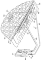
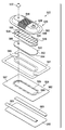
도 1은 일부분이 단면으로 도시된, 제1 감압 인터페이스 및 제2 감압 인터페이스를 포함하는 선형 상처를 갖는 조직 부위를 치료하기 위한 예시적인 감압 시스템의 개략적인 사시도이다.
도 2는 도 1의 예시적인 감압 시스템의 개략적인, 단면도이다.
도 3a는 감압 시스템의 일부분을 형성하는 예시적인 드레싱 볼스터의 일부분의 개략적인, 사시도이다.
도 3b는 감압 시스템의 일부분을 형성하는 예시적인 드레싱 볼스터의 일부분의 개략적인, 사시도이다.
도 4는 선형 상처를 갖는 조직 부위를 치료하기 위한 상처 드레싱 조립체의 일부분의 개략적인, 사시도이다.
도 5는 선형 상처를 갖는 조직 부위를 치료하기 위한 상처 드레싱 조립체의 일부분의 개략적인, 사시도이다.
도 6은 제2 감압 인터페이스를 구비하는 상처 드레싱 조립체의 예시적인 구현예의, 일부분이 단면으로, 부분 분해의, 개략적인 사시도이다.
도 6a는 도 6의 상처 드레싱 조립체의 일부분의 세부사항이다.
도 7은 선형 상처를 갖는 조직 부위를 치료하기 위한 그리고 피하 전달 도관을 피하 조직 부위에 제공하기 위한 예시적인 감압 시스템의 개략적인, 측단면도이다.
도 8은 제2 감압 인터페이스를 포함하는 상처 드레싱 조립체의 예시적인 구현예의 도식적인, 분해의, 사시도이다.
도 9는 제1 감압 인터페이스 및 제2 감압 인터페이스를 구비하는 상처 드레싱 조립체의 예시적인 구현예의 개략적인, 사시도이다.1 is a schematic perspective view of an exemplary decompression system for treating a tissue site having a linear wound including a first decompression interface and a second decompression interface, a portion of which is shown in cross section.
2 is a schematic, cross-sectional view of the exemplary pressure reducing system of FIG. 1.
3A is a schematic, perspective view of a portion of an exemplary dressing bolster forming part of a pressure reducing system.
3B is a schematic, perspective view of a portion of an exemplary dressing bolster forming part of a pressure reducing system.
4 is a schematic, perspective view of a portion of a wound dressing assembly for treating a tissue site having a linear wound.
5 is a schematic, perspective view of a portion of a wound dressing assembly for treating a tissue site having a linear wound.
6 is a schematic perspective view of a partial exploded, partial in cross section, of an exemplary embodiment of a wound dressing assembly having a second pressure sensitive interface.
6A is a detail of a portion of the wound dressing assembly of FIG. 6.
7 is a schematic, side cross-sectional view of an exemplary decompression system for treating a tissue site with a linear wound and for providing a subcutaneous delivery conduit to a subcutaneous tissue site.
8 is a schematic, exploded, perspective view of an exemplary embodiment of a wound dressing assembly that includes a second pressure sensitive interface.
9 is a schematic, perspective view of an exemplary embodiment of a wound dressing assembly having a first pressure sensitive interface and a second pressure sensitive interface.
아래의 예시적인 구현예들의 상세한 설명에서, 본원의 일부분을 형성하는 첨부된 도면들에 대해 참조가 이루어진다. 이러한 구현예들은 통상의 기술자들이 본 발명을 실시하는 것이 가능하도록 충분히 상세하게 설명되며, 다른 구현예들이 사용될 수 있고 논리 구조적, 기계적, 전기적 및 화학적인 변화들이 본 발명의 사상 또는 범위로부터 벗어나지 않고 만들어 질 수 있는 것으로 이해된다. 통상의 기술자가 여기에 설명된 구현예들을 실시할 수 있게 하는데 필요하지 않은 세부사항을 피하기 위하여, 상세한 설명은 통상의 기술자에게 알려진 특정한 정보를 생략할 수 있다. 아래의 상세한 설명은, 그러므로, 제한적인 의미에서 취해지지 않으며, 예시적인 구현예들의 범위는 첨부된 청구항들에 의해서만 정의된다.In the detailed description of the exemplary embodiments below, reference is made to the accompanying drawings that form a part hereof. These embodiments are described in sufficient detail to enable those skilled in the art to practice the invention, and other embodiments may be used and logical structural, mechanical, electrical, and chemical changes may be made without departing from the spirit or scope of the invention. It is understood that it can be lost. In order to avoid details that are not necessary to enable a person skilled in the art to practice the embodiments described herein, the detailed description may omit specific information known to the person skilled in the art. The following detailed description, therefore, is not to be taken in a limiting sense, and the scope of example embodiments is defined only by the appended claims.
수술 또는 다른 의료 상태에 따라, 환자는 환자의 표피의 선형 상처의 근처 또는 하부에 위치한 피하 상처를 가질 수 있다. 예를 들면, 환자로부터 피하 조직을 제거하기 위한 수술 후에, 환자는 수술절개의 결과로 선형 상처를 가질 수 있다. 환자는 또한 수술, 즉, 피하 상처 또는 결함에 따라 치유할 필요가 있는 피부 하부 부위를 가질 수 있다.Depending on the surgery or other medical condition, the patient may have a subcutaneous wound located near or below the linear wound of the patient's epidermis. For example, after surgery to remove subcutaneous tissue from a patient, the patient may have a linear wound as a result of surgical incision. The patient may also have subcutaneous areas that need to be cured following surgery, ie subcutaneous wounds or defects.
그러한 경우에, 피하 상처는 치료 과정 중에 유체들을 삼출 또는 수집할 수 있고, 삼출액을 수집하고 피하 상처의 조직 부위에서 원치 않는 유체들의 수집을 차단하기 위하여 드레인이 선형 상처의 단부 또는 근처에 삽입될 수 있다. 드레인은 피하 전달 도관으로 지칭될 수 있는, 선형 상처의 일단부에서 환자의 몸으로부터 배출되도록 구성된 드레인 튜브에 연결될 수 있다. 피하 전달 도관의 일종인 드레인 튜브는 위생적으로 상처 삼출액을 수집할 목적으로 드레인에 연결될 수 있다. 동시에, 감압 치료 방법이 수술 중에 발생되는 선형 상처를 치료하기 위하여 적용될 수 있다. 감압 치료 방법은 선형 상처를 포함하는 치료-영역에 걸친 유체 밀봉의 형성을 포함한다.In such cases, the subcutaneous wound may exudate or collect fluids during the course of treatment, and a drain may be inserted at or near the end of the linear wound to collect the exudates and block the collection of unwanted fluids at the tissue site of the subcutaneous wound. have. The drain may be connected to a drain tube configured to exit from the patient's body at one end of the linear wound, which may be referred to as a subcutaneous delivery conduit. A drain tube, a type of subcutaneous delivery conduit, may be connected to the drain for the purpose of hygienically collecting wound exudates. At the same time, decompression treatment methods can be applied to treat linear wounds occurring during surgery. Decompression treatment methods include the formation of a fluid seal over a treatment-area that includes a linear wound.
유체 밀봉은 통상적으로 감압을 상처 부위에 전달하는 시스템의 중요하면서 손상되기 쉬운 특징이다. 유체 밀봉의 임의의 파손은 셧다운될 수 있거나 전달 시스템을 약화시킬 수 있는 누수를 일으킬 수 있는데, 이는 시스템이 누수를 아주 잘 견디지 못하는 경향이 있게 때문이다. 유체 밀봉을 제공하는 하나의 방법은 환자의 표피를 밀봉하는 유연한(pliable) 드레이프, 또는 오버-드레이프를 포함하는 상처 드레싱 조립체를 제공하는 것일 수 있다. 유체 밀봉을 형성함으로써, 오버 -드레이프는 치료-영역과, 외부 환경으로 지칭될 수도 있는 대기 환경 사이의 압력 차이를 유지할 수 있다. 본 문서 전체에서 사용되는 바와 같이, "또는"이라는 용어는 상호 배타성을 요구하지 않는다. 드레인 튜브가 있는 경우에는, 드레인 튜브가 오버-드레이프가 환자의 표피에 대하여 밀봉하는 것을 방해할 수 있기 때문에 감압 상처 드레싱 조립체의 적용은 곤란할 수 있다. 치료 공급자가 드레인 튜브 위에 오버-드레이프를 적용함으로써 치료-영역을 밀봉하려는 경우에는, 누수가 발생할 수 있다. 또한, 유체 밀봉이 될 수 있다고 하더라도, 드레인 튜브의 움직임이 밀봉을 전체적으로 방해할 수 있고 치료-영역에서 감압의 손실을 가져올 수 있으므로 조직 부위에서 감압의 필요한 양을 유지하는 능력을 약화시킨다. 그러므로 치료-부위와 대기 환경 사이의 유체 밀봉을 방해하지 않으면서 (드레인으로부터 드레인 수집 영역으로) 감압 치료-영역을 통과하기 위해, 드레인 튜브를 허용하는 드레싱 조립체 또는 인터페이스, 또는 피하 전달 도관을 갖는 것이 바람직하다. Fluid sealing is typically an important and fragile feature of the system that delivers reduced pressure to the wound site. Any breakage of the fluid seal can cause a leak that can shut down or weaken the delivery system because the system tends to withstand leaks very well. One method of providing a fluid seal may be to provide a wound dressing assembly comprising a pliable drape, or over-drape, that seals the epidermis of the patient. By forming a fluid seal, the over-drape can maintain a pressure difference between the treatment-area and the atmospheric environment, which may be referred to as the external environment. As used throughout this document, the term "or" does not require mutual exclusion. In the case of a drain tube, application of the pressure-sensitive wound dressing assembly can be difficult because the drain tube may prevent the over-drape from sealing to the epidermis of the patient. If a treatment provider attempts to seal the treatment area by applying an over-drape over the drain tube, leakage may occur. In addition, even if fluid sealing can be achieved, the movement of the drain tube can hinder the sealing as a whole and can result in a loss of decompression in the treatment-area, thus weakening the ability to maintain the required amount of decompression at the tissue site. It is therefore desirable to have a dressing assembly or interface, or a subcutaneous delivery conduit to allow a drain tube to pass through the decompression treatment-area (from the drain to the drain collection region) without disturbing the fluid seal between the treatment-site and the atmospheric environment. desirable.
이제 도 1을 주로 참조하면, 드레인(136)을 통한 상처 삼출액을 수집하는 동시에 선형 상처(114)를 포함하는 조직 부위(112)를 치료하기 위한 감압 치료 시스템(110)의 예시적인 구현예가 제시된다. 조직 부위(112)는 선형 상처(114)에 관계된다. 조직 부위(112)는 골조직, 지방 조직, 근 조직, 진피 조직, 맥관 조직(vascular tissue), 결합 조직, 연골, 힘줄, 인대 또는 임의의 다른 조직을 포함하는 임의의 인간, 동물 또는 다른 유기체의 신체 조직일 수 있다. 조직부위(112)의 치료는 유체, 예를 들어 삼출액의 제거를 포함할 수 있다. 조직 부위(112)는 표피(116)에 도시되지만, 일부 경우에서는 진피(118), 및 피하 조직(120)을 포함할 수도 있다. 감압 치료 시스템(110)은 또한 다른 조직 부위들에 사용될 수도 있다.Referring primarily to FIG. 1, an exemplary embodiment of a
감압 치료 시스템(110)은 상처 드레싱 조립체(122) 및 감압 서브시스템(111)을 포함한다. 감압 치료 시스템(110)은 선형 상처(114) 위에 놓인 감압 상처 드레싱 조립체(122)의 맥락으로 도시되지만, 감압 치료 시스템(110)이 개방 상처들을 포함하여 다른 조직 부위들 위에도 사용될 수 있는 것으로 이해되어야 한다. 상처 드레싱 조립체(122)는 매니폴드의 기능을 하는 드레싱 볼스터(124), 오버-드레이프(126), 및 감압 전달 도관(130)을 수용하기 위한 제1 감압 인터페이스(128)를 포함한다. 감압 전달 도관(130)은 감압 서브시스템(111)에 유체적으로 연결된다.
기능적으로, 감압 서브시스템(111)에 의해 발생되는 감압은 감압 전달 도관(130)을 통하여 제1 감압 인터페이스(128)로 전달된다. 예시적인 일 구현예에서, 제1 감압 인터페이스(128)는 텍사스의 산 안토니오(San Antonio)의 KCI로부터 구매 가능한 T.R.A.C.® 패드 또는 Sensa T.R.A.C.® 패드이다. 제1 감압 인터페이스(128)는 감압이 드레싱 볼스터(124)에 전달될 수 있도록 한다. 다른 구현예에서, 감압 인터페이스(128)는 사용되지 않는다. 대신에, 루멘(또는 관)이 오버-드레이프(126)를 통하여 직접 드레싱 볼스터(124)에 놓여진다.Functionally, the decompression generated by the
상처 드레싱 조립체(122)는 감압으로 치료되어야 하는 조직 부위(112)를 포함하는 영역 위에 유체 밀봉을 제공한다. 유체 밀봉은 특정한 감압 소스(들) 또는 포함된 서브시스템으로 주어진 필요한 부위에 감압을 유지하기에 적절한 밀봉이다.
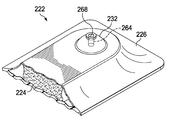
또한 상처 드레싱 조립체(122)는 제2 감압 인터페이스(132)를 포함한다. 제2 감압 인터페이스(132)는 접착제, 본드, 용접(예를 들어, 초음파, 열, 또는 RF 용접), 또는 시멘트(미도시)에 의하여 오버-드레이프(126)에 고정된다. 제2 감압 인터페이스(132)는 조직 부위(112) 위의 유체 밀봉의 완전한 상태를 유지하면서 피하 전달 도관(134)이 드레싱 볼스터(124) 및 오버-드레이프(126)를 통과할 수 있도록 한다. 일 구현예에서, 제2 감압 인터페이스(132)는 오버-드레이프(126)에 용접되거나 접착된 성형 플라스틱 구성요소를 포함한다.The
도 1의 제2 감압 인터페이스(132)는 상처 드레싱 조립체(122)를 통하여 피하 전달 도관(134)을 전달하기 위하여 사용자 또는 치료 제공자가 제2 감압 인터페이스(132)의 외면에 대하여 힘을 가할 수 있도록 구성된다. 동시에, 사용자는 오버-드레이프(126)를 뚫기에 충분한 힘으로 제2 감압 인터페이스(132)의 위치에서 오버-드레이프(126)에 대하여 피하 전달 도관(134)을 누를 수 있다. 제2 감압 인터페이스(132) 외부에 유체 밀봉을 제공하기 위한 오버-드레이프(126)의 성능이 약화되지 않고 오버-드레이프(126)가 뚫릴 수 있도록 제2 감압 인터페이스(132)는 오버-드레이프(126)를 보강한다. 일 구현예에서, 구멍은 제2 감압 인터페이스(132)에서 오버-드레이프 내에 형성되어 상처 드레싱 조립체(122)를 통한 경로를 용이하게 한다.The
제2 감압 인터페이스(132)는 임의의 형상 및 크기를 가질 수 있다. 예를 들어, 제2 감압 인터페이스(132)가 평평한 상부 및 하부면들 및 구멍(168)을 구비하는 제2 감압 인터페이스(132)는 실질적으로 도 1에 도시된 바와 같은 형상으로 성형될 수 있다. 구멍(168)은 피하 전달 도관(134)이 제2 감압 인터페이스(132)를 통하여 삽입될 때 피하 전달 도관(134)에 대하여 반경방향 압축력을 발생시킬 수 있도록 크기가 정해질 수 있다. 예를 들어, 인터페이스 끼워 맞춤이 구멍(168)과 피하 전달 도관(134) 사이에 형성될 수 있다. 예시적인 일 구현예에 따르면, 제2 감압 인터페이스(132)는 내경(D1)을 갖는 구멍(168)을 구비하는 인터페이스 본체(133)로부터 형성된 접속관(131)을 포함할 수 있다. 피하 전달 도관(134)은 외경(D2)을 가질 수 있다. 직경들은 식 D1 < D2에 의해 서로 관련된다. D1은 D2보다 아주 조금 작아서 유체 밀봉이 인터페이스 끼워 맞춤에 의하여 형성된다. 다른 구현예에서, D1은 D2와 동등할 수 있다.The second
제2 감압 인터페이스(132)는 또한 제2 감압 인터페이스(132)의 두께가 구멍에서 증가되어 점차적으로 외부 에지에서 최소 두께로 감소되도록 테이퍼될 수 있다. 제2 감압 인터페이스(132)의 두께는 에지로부터 구멍(168)의 경계까지 선형 또는 곡선으로 점차적으로 증가될 수 있다. 제2 감압 인터페이스(132)는 둥글거나 돔 형태의 형상을 가질 수 있다. 다른 형상들도 또한 가능하다.The second
피하 전달 도관(134)은 상처 삼출액이 피하 조직 부위(138)로부터 드레인(136)으로 흐를 수 있도록 기능한다. 피하 전달 도관(134)은 감압 서브시스템(111) 또는 제2 감압 서브시스템(미도시)에 유체적으로 연결될 수 있다. 그러므로, 감압 전달 도관(130) 및 피하 전달 도관(134) 모두는 감압을 제공하며 감압 서브시스템(111)에 연결될 수 있다. 여기서, 감압 전달 도관(130)은 감압 치료요법을 조직 부위(112)에 적용하도록 감압 서브시스템(111)에 연결된다. 피하 전달 도관(134) 또한 감압 서브시스템(111), 또는 유체, 또는 삼출액을 드레인(136)으로부터 배출시키기 위한 별도의 감압 서브시스템(미도시)에 연결될 수 있다.
감압은 치료가 행해지는 조직 부위에서의 대기압보다 작은 압력이다. 대부분의 경우에, 이러한 감압은 환자가 있는 곳의 대기압보다 작을 것이다. 대안적으로, 감압은 조직 부위의 유체 정압보다 작을 수 있다. 만약 다르게 표시되어 있지 않다면, 여기에 언급된 압력값들은 게이지 압력들이다. 전달된 감압은 일정하거나 (패턴이 있거나 또는 임의로) 변화될 수 있고 연속적으로 또는 간헐적으로 전달될 수 있다. 여기서의 사용과 일관되게, 다르게 표시되어 있지 않다면, 감압 또는 진공압력에서의 증가는 통상적으로 절대 압력에서 상대적인 감소를 지칭한다.Decompression is a pressure less than atmospheric pressure at the tissue site at which treatment is performed. In most cases, this decompression will be less than the atmospheric pressure where the patient is. Alternatively, the reduced pressure may be less than the hydrostatic pressure of the tissue site. If not indicated otherwise, the pressure values mentioned here are gauge pressures. The delivered depressurization may be constant (patterned or optionally) and may be delivered continuously or intermittently. Consistent with the use herein, unless otherwise indicated, an increase in reduced pressure or vacuum pressure typically refers to a relative decrease in absolute pressure.
몇몇 구현예들에서, 피하 조직 부위(138) 보다 선형 상처(114)의 조직 부위(112)에서 상이한 감압량이 필요할 수 있다. 그러한 구현예들에서, 피하 전달 도관(134) 및 감압 전달 도관(130)은 상이한 감압 소스들에 유체적으로 연결될 수 있고 각각과 연관된 상이한 유체 저장소들을 포함할 수 있다. 대안적으로, 전달 도관들(130, 134)은 단일 감압 서브시스템(111)이 각각의 관들에 상이한 감압량들을 공급할 수 있도록 하는 하나 이상의 압력 조절기(140)들을 통하여 동일한 감압 서브시스템(111)에 연결될 수 있다. 몇몇 구현예들에서, 피하 조직 부위(138)와 동일한 감압량이 선형 상처(114)의 조직 부위(112)에 필요할 수 있다. 이러한 구현예들에서, 피하 전달 도관(134) 및 감압 전달 도관(130)은 압력 조절기들 필요 없이 동일한 감압 소스(109)에 유체적으로 연결될 수 있다.In some embodiments, a different amount of decompression may be needed at the
이제 주로 도 2를 참조하면, 도 1의 상처 드레싱 조립체(122)의 측단면도가 도시된다. 도시된 바와 같은 상처 드레싱 조립체(122)는 드레싱 볼스터(124)에 연결될 수 있고 드레싱 볼스터(124) 재료와 환자의 표피(116) 사이에 놓여 있는 선택적인 내부 편의층(142)을 포함한다. 상처 드레싱 조립체(122)는 또한 드레싱 볼스터(124)에 유연성(flexibility)을 부가하기 위한 (횡방향 또는 종방향) 유연성 노치들(144)을 포함할 수 있다. 또한, 상처 드레싱 조립체(122)의 오버-드레이프(126)는 상처 드레싱 조립체(122)에 유연성을 부가하기 위한 주름(146) 또는 노치 또는 융선을 포함할 수 있다. Referring now primarily to FIG. 2, a cross-sectional side view of the
감압 전달 도관(130) 및 드레싱 볼스터(124)에 유체적으로 연결된 제1 감압 인터페이스(128) 이외에, 상처 드레싱 조립체(122) 또한 제2 감압 인터페이스(132)를 포함한다. 제2 감압 인터페이스(132)는 피하 전달 도관(134)의 존재를 수용하도록 기능한다. 피하 전달 도관(134)은 조직 부위(112)에 감압을 적용하기 위한 감압 치료 시스템(110)의 성능을 방해하지 않으면서 드레인(136)에 유체적으로 연결된 드레인 튜브로서 기능한다. 제2 감압 인터페이스(132)는 조직 부위(112)에서 감압 치료요법을 방해하거나 정지시키는 누수를 발생시키지 않으면서 드레인(136)에 감압 소스를 유체적으로 연결시킨다.In addition to the first
상처 드레싱 조립체(122)의 드레싱 볼스터(124)는 제1 측면(148) 및 제2 내향측면(150)을 구비한다. 드레싱 볼스터(124)는 임의의 볼스터 재료, 또는 다공성 투과 폼 또는 폼 유사 재료, 경로들로 형성된 부재, 이식편, 또는 거즈와 같은 진공 공간, 또는 치료 공간을 제공하는 매니폴드 재료로부터 형성될 수 있다. 더욱 자세한, 제한적이지 않은 실시예에서와 같이, 드레싱 볼스터(124)는 감압 하에서 상처 유체에 대해 양호한 투과성을 허용하는 망상의 개방 셀 폴리우레탄 또는 폴리에테르 폼일 수 있다. 하나의 그러한 사용되어왔던 폼 재료는 텍사스, 산 안토니오(San Antonio)의 Kinetic Concepts, Inc. (KCI)로부터 구매가능한 VAC® GranuFoam® 재료이다. 임의의 재료 또는 재료들의 조합이 매니폴드 재료가 감압을 분배하도록 작동 가능하다면 매니폴드 재료로 사용될 수 있다.The dressing bolster 124 of the
매니폴드는 일반적으로 감압을 조직 부위로 적용하거나 유체를 조직부위로 전달하거나 유체를 조직 부위로부터 제거하는 것을 보조하도록 제공되는 물질 또는 구조이다. 매니폴드는 통상적으로 복수의 유동 채널들 또는 경로들을 포함한다. 복수의 유동 채널들은 매니폴드 주위의 조직 영역에 제공되고 조직 영역으로부터 제거되는 유체의 분배를 개선하도록 상호 연결될 수 있다. 매니폴드의 예시들은, 이에 제한되지는 않으나 유동 채널들, 셀 형태 폼 (예를 들어 개방 셀 폼, 다공성 조직 모음, 및 액체) 겔, 그리고 유동 채널들을 포함하거나 포함하도록 경화되는 폼들을 형성하도록 배열되는 구조적인 요소들을 갖는 장치들을 포함할 수 있다. 일부 구현예에서, 매니폴드는 다수의 층 또는 기재들에 의하여 형성될 수 있다. 또한, 다층을 구비한 매니폴드의 일부 구현예들에서, 사용 중에 환자에 가장 가까운 층은 가장 덜 친수성이면서 가장 소수성 재료일 수 있다.Manifolds are generally materials or structures provided to assist in applying reduced pressure to a tissue site, delivering fluid to a tissue site, or removing fluid from a tissue site. The manifold typically includes a plurality of flow channels or paths. The plurality of flow channels can be interconnected to improve the distribution of fluid provided to and removed from the tissue region around the manifold. Examples of manifolds are arranged to form flow channels, cell shaped foam (eg, open cell foam, porous tissue collection, and liquid) gel, and foams that are cured to include or include flow channels. Devices with structural elements to be included. In some embodiments, the manifold can be formed by multiple layers or substrates. In addition, in some embodiments of a manifold with multiple layers, the layer closest to the patient during use may be the least hydrophilic and the most hydrophobic material.
GranuFoam® 재료의 망상 기공들은 매니폴드 기능을 수행하는데 도움이 되지만, 또한 다른 재료들도 사용될 수 있다. GranuFoam® 재료보다 더 높거나 더 낮은, 밀도(더 작은 기공 크기)를 갖는 재료가 일부 상황에서는 바람직할 수 있다. 많은 가능한 재료들 중에서, 다음의 것이 사용될 수 있다: GranuFoam® 재료, Foamex®기술 폼(www.foamex.com), 거즈, 유연한 채널 함유 부재, 이식편 등. 일부 예들에서 은 이온을 마이크로-결합 과정에서 폼에 첨가하거나 항균제와 같은 다른 물질들을 재료에 첨가하는 것이 바람직할 수 있다.Reticulated pores of GranuFoam ® materials help to perform the manifold function, but other materials can also be used. Materials having a density (smaller pore size), higher or lower than GranuFoam ® materials, may be desirable in some situations. Among many possible materials, the following may be used: GranuFoam ® materials, Foamex ® technical foams (www.foamex.com), gauze, flexible channel-containing members, grafts and the like. In some examples, it may be desirable to add silver ions to the foam during the micro-bonding process or to add other materials, such as antimicrobials, to the material.
매니폴드는 통상적으로 매니폴드 주변 조직 부위로 제공되고 조직 부위로부터 제거되는 유체들을 분배하는 복수의 유동 채널들 또는 경로들을 포함한다. 여기서, 매니폴드는 피하 조직 부위와 접촉하여 배치될 수 있고 피하 조직 부위에 감압을 분배할 수 있는 생체적합성 재료일 수 있다. 매니폴드 재료는 감압 치료 후 환자 신체에 남아 있을 수 있는 생체흡수성 재료를 포함할 수 있다. 일반적으로 생체흡수성 재료는 효소적으로나 화학적으로 생체 내 단순 화학 종으로 분해되는 재료이며, 신진대사의 배출작용에 의하여 신체로부터 제거될 수 있다. 적합한 생체흡수성 재료들은, 이에 제한되지는 않으나, 폴리 유산의 중합체 혼합물(PLA) 및 폴리글리콜산(PGA)를 포함할 수 있다. 중합체 혼합물은 또한 이에 제한되지는 않으나 폴리카보네이트(polycarbonate), 폴리푸마레이트(polyfumarate), 및 카프라락톤(capralactone)을 포함할 수 있다. 매니폴드 재료는 또한 신 세포-성장을 위한 스캐폴드(scaffold)로서 제공될 수 있고, 또는 스캐폴드 재료가 세포-성장을 촉진시키기 위하여 매니폴드 재료와 함께 사용될 수 있다. 스케폴드는 세포 성장을 위한 템플릿을 제공하는 3차원 다공성 구조와 같은 세포들의 성장 또는 조직의 형성을 증가시키거나 촉진시키는데 사용되는 물질 또는 구조이다. 스캐폴드 재료들의 예시적인 실시예들은 인산칼슘, 콜라겐, PLA/PGA, 산호 수산화인회석(coral hydroxy apatites), 탄화물, 또는 가공된 동종이식(allograft) 재료들을 포함한다.The manifold typically includes a plurality of flow channels or pathways that distribute fluids that are provided to and removed from the tissue site around the manifold. Here, the manifold can be a biocompatible material that can be placed in contact with the subcutaneous tissue site and can distribute the decompression to the subcutaneous tissue site. The manifold material may comprise a bioabsorbable material that may remain in the patient's body after decompression treatment. Generally, bioabsorbable materials are enzymatically or chemically decomposed into simple chemical species in vivo, and can be removed from the body by the action of metabolism. Suitable bioabsorbable materials may include, but are not limited to, a polymer mixture of polylactic acid (PLA) and polyglycolic acid (PGA). The polymer mixture can also include, but is not limited to, polycarbonate, polyfumarate, and capralactone. The manifold material can also be provided as a scaffold for renal cell-growth, or the scaffold material can be used with the manifold material to promote cell-growth. Scaffolds are materials or structures used to increase or promote the growth or formation of tissues of cells, such as three-dimensional porous structures that provide a template for cell growth. Exemplary embodiments of scaffold materials include calcium phosphate, collagen, PLA / PGA, coral hydroxy apatites, carbides, or engineered allograft materials.
일 예시적인 구현예에서, 드레싱 볼스터(124)는 다음과 같이 제조된다. 도 2 및 6에 도시된 바와 같이 GranuFoam® 재료의 폼 블럭, 예를 들면, 1.21 미터 X 1.8 미터 X 0.5 미터 블록이 19mm 높이를 갖도록 절단되고, 톱이 횡방향 홈들, 또는 횡방향 유연성 노치들을 형성하는데 사용된다. 이어서, 내부 편의층(142)일 수 있는 건층(dry layer)이 제2, 또는 밑면, 표면 위에 적층되거나 부착된다. 폼 블럭은 이어서 개별적인 드레싱 볼스터들(124)을 형성하도록 다이 절단기를 사용하여 절단된다.In one exemplary embodiment, the dressing bolster 124 is made as follows. Foam blocks of GranuFoam ® material, for example 1.21 meters by 1.8 meters by 0.5 meters, are cut to have a height of 19 mm as shown in FIGS. 2 and 6, and the saw forms transverse grooves, or transverse flexible notches. It is used to A dry layer, which may be an
선택적인 내부 편의층(142)은 제1 측면(152) 및 제2내향 측면(154)를 구비한다. 선택적인 내부 편의층(142)의 제1 측면(152)은, 예를 들면, 열 결합 또는 임의의 다른 기술에 의하여, 드레싱 볼스터(124)의 제2 내향 측면(150)에 결합될 수 있다. 내부 편의층(142)은 통상적으로 드레싱 볼스터(124)가 환자의 표피(116)에 인접하여 배치될 때 환자에게 편안함을 제공한다. 내부 편의층(142)은 유체 전송이 내부 편의층(142)을 통과하는 동안에 피부 염증이나 불편함을 방지하는데 도움이 되는 임의의 재료일 수 있다. 한정되지 않은 예시들로서, 직물, 탄성 재료 또는 폴리에스테르 니트 섬유 기재가 사용될 수 있다. 다른 한정되지 않는 예시로서, 남 캐롤라이나(South Carolina), 스타탄버그(Spartanburg)의 Milliken & Company, Inc.의 사업부인 Milliken Chemical의 InterDryTM 섬유 재료, 가 사용될 수 있다. 내부 편의층(142)은 은과 같은 항균성 물질을 포함할 수 있으며, 통기성 건층과 같이 제조될 수 있다.The optional
드레싱 볼스터(124)는 제1 측면(148) 위에 드레싱 볼스터(124)에서 횡방향 절단구멍들일 수 있는 복수의 유연성 노치들(144) 또는 리세스들을 포함할 수 있다. 또한, 유연성 노치들(144)은 하나 이상의 종방향 노치들, 또는 종방향 절단구멍들, 또는 다른 절단구멍들일 수 있다. 절단구멍들은 톱(또는 노치된 날), 고온 칼, 또는 다른 장치를 사용하여 제조될 수 있다. 유연성 노치들은 드레싱 볼스터(124)의 유연성을 증가시킨다. 증가된 유연성은 상처 드레싱 조립체(122)가 환자의 관절 영역 또는 다른 움직임 영역 위에 적용되는 경우에 특히 유용하다. 예를 들어, 드레싱 볼스터(124)가 무릎에 사용된다면, 드레싱 볼스터(124)는 100% 이상 휘어지거나 늘어나야 할 필요가 있을 수 있으며 유연성 노치들이 필요한 유연성을 제공하는데 도움이 된다. 유연성 노치들은 또한 육각형, 슬릿, 또는 사각형과 같은 다양한 형상을 가질 수 있다.The dressing bolster 124 may include a plurality of
드레싱 볼스터(124)는 드레싱 볼스터(124)의 제2 내향 측면(150)에 대하여 직교하는 횡방향 에지들로 형성될 수 있다. 횡방향 에지들은 또한 경사진 에지 또는 각진 에지로 형성될 수 있다. 각지거나 경사진 에지는 드레싱 볼스터와 환자 표피(116) 간의 전단 응력을 분산시킬 수 있다. 드레싱 볼스터(124)는 또한 둥근 측면들을 구비할 수 있다. 드레싱 볼스터(124)는 피하 전달 도관(134)이 상대적으로 적은 힘으로 드레싱 볼스터(124)를 관통하도록 볼스터를 관통하여 형성된 작은 구멍 또는 절단구멍을 구비할 수 있다.The dressing bolster 124 may be formed with transverse edges orthogonal to the second
오버-드레이프(126)로서 도시된, 밀봉 부재는 드레싱 볼스터(124) 위 및 환자 표피(116)의 적어도 일부분에 유체 밀봉을 제공한다. 그러한 바와 같이, 오버-드레이프(126)는 유체 밀봉을 가능하게 하는 임의의 재료로부터 형성될 수 있다. 오버-드레이프(126)는 표피(116) 또는 가스켓 재료에 대하여 압력-민감형 접착제와 같은, 밀봉 기구에 의하여 밀봉될 수 있다.The sealing member, shown as
밀봉 기구는 접착 밀봉 테이프, 또는 드레이프 테이프, 또는 스트립; 양면 드레이프 테이프; 압력-민감형 접착체; 풀; 수성콜로이드(hydrocolloid); 하이드로겔(hydrogel); 또는 다른 밀봉 수단과 같은 많은 형태를 취할 수 있다. 여기에서 설명된 바와 같이, 밀봉 재료는 보편적으로 오버-드레이프(126)이다. 만약 테이프가 사용된다면, 테이프는 사전-적용된, 압력-민감형 접착제로 오버-드레이프(126)와 동일한 재료로 형성될 수 있다. 압력-민감형 접착제는 오버-드레이프(126)의 제2 내향 측면(158) 또는 그의 일부분 위에 적용될 수 있다. 압력-민감형 접착제는 오버-드레이프(126)와 표피(116) 간의 유체 밀봉을 제공하는데 도움이 된다. 여기서 사용되는 바와 같이, 유체 밀봉은 또한 표피(116)에 대하여 가스켓을 포함할 있다. 밀봉 부재가 표피에 고정되기 전에, 압력-민감형 접착제를 덮고 있는 제거가능한 스트립들, 또는 해제 라이너들은 제거될 수 있다.The sealing mechanism may be an adhesive sealing tape, or drape tape, or a strip; Double sided drape tape; Pressure-sensitive adhesives; pool; Hydrocolloids; Hydrogels; Or many forms such as other sealing means. As described herein, the sealing material is universally over-draped 126. If tape is used, the tape may be formed of the same material as the over-drape 126 with a pre-applied, pressure-sensitive adhesive. The pressure-sensitive adhesive may be applied over the second
밀봉 부재, 또는 오버-드레이프(126)는 유체 밀봉을 제공하는 탄성중합체 재료(elastomeric material) 또는 임의의 재료 또는 물질일 수 있다. 탄성중합체의 예시들은, 이에 한정되지는 않으나, 천연 고무, 폴리이소프렌(polyisoprene), 스티렌 부타디엔 고무(styrene butadiene rubber), 클로로프렌 고무(chloroprene rubber), 폴리부타디엔(polybutadiene), 니트릴 고무(nitrile rubber), 부틸 고무(butyl rubber), 에틸렌 프로필렌 고무(ethylene propylene rubber), 에틸렌 프로필렌 디엔 모노머(ethylene propylene diene monomer), 클로로술포네이트 폴리에틸렌(chlorosulfonated polyethylene), 폴리설파이드 고무(polysulfide rubber), 폴리우레탄, EVA 필름, 코-폴리에스테르, 및 실리콘을 포함할 수 있다. 또한, 밀봉 부재 재료들은 Avery Dennison사로부터 구매가능한 것과 같은 실리콘 드레이프, 3M Tegaderm® 드레이프, 아크릴 드레이프 또는 절개 드레이프를 포함할 수 있다.The sealing member, or
밀봉 부재, 또는 오버-드레이프(126)는 제1 밀봉 부재 또는 드레이프 부분(160) 및 제2 밀봉 부재 또는 드레이프 부분(162)를 포함할 수 있다. 제1 밀봉 드레이프 부분(160)은 드레싱 볼스터(124)의 제1 측면(148) 위로 연장된다. 오버-드레이프(126)는 제1 측면 및 제2 내향 측면(명시적으로 도시되지 않음)을 구비하는 밀봉 부재 플랜지, 또는 밀봉 부재 연장을 형성하도록 더 연장된다. 구멍(명시적으로 도시되진 않으나 도 8의 559와 유사함)은 감압 서브시스템(111)과 유체적으로 연결된 제1 감압 인터페이스(128)와 유체 연통할 수 있도록 오버-드레이프(126)의 일부분 위에 형성된다.The sealing member, or
오버-드레이프 연장의 제2 내향 측면은 제2 밀봉 드레이프 부분(162)의 제1 측면(도 1의 방향에 대하여 상측) 위에 배치되며, 접착제, 본드, 용접(예를 들어, 초음파, 열 또는 RF 용접), 또는 시멘트(미도시)와 같은 것에 의하여 연결된다. 대안적으로, 제1 밀봉 드레이프 부분(160) 및 제2 밀봉 드레이프 부분(162)은 일체형으로 형성될 수 있다. 제1 밀봉 드레이프 부분(160)은 복수의 주름들(146), 또는 신축성 영역들을 포함할 수 있다. 주름들(146)은, 필요하다면, 부가적인 드레이프 재료가 사용가능하게 되거나, 신축되거나, 또는 움직이도록 한다. 예를 들면, 상처 드레싱 조립체(122)가 관절 위에 사용된다면, 관절이 휠 경우에, 부가적인 드레이프 재료가 관절의 움직임을 수용하는데 유용할 수 있다. 주름들(146)은 그러한 움직임을 가능하게 한다.The second inward side of the over-drape extension is disposed above the first side (upper side with respect to the direction of FIG. 1) of the second
적용 전에, 하나 이상의 해제 부재들(도시되진 않았으나 도 8의 581 및 583와 유사함)은 제2 밀봉 드레이프 부분(162)의 제1 측면에 해제가능하게 연결될 수 있다. 해제 부재들은 강성을 제공하며 상처 드레싱 조립체(122)의 배치 중에 도움이 된다. 해제 부재들은 통상적으로 제2 밀봉 드레이프 부분(162)의 제1 측면 위에 부착된 캐스팅 종이 또는 필름 중에 하나이다.Prior to application, one or more release members (not shown but similar to 581 and 583 in FIG. 8) may be releasably connected to the first side of the second
감압 서브시스템(111)은 많은 상이한 형태들을 취할 수 있는 적어도 하나의 감압 소스(109)를 포함한다. 감압 소스(109)는 감압 치료 시스템(110)의 일부분으로서 감압을 제공한다. 감압 소스(109)는 감압 전달 도관(130)에 의하여 제1 감압 인터페이스(128)에 유체적으로 연결된다.The
감압 서브시스템(111)은 하나 이상의 저장 영역(113) 또는 캐니스터 영역을 구비할 수 있다. 저장 영역(113) 또는 캐니스터 영역은 조직 부위(112) 또는 피하 조직 부위(138)로부터의 액체의 유입으로부터 공압 시스템을 보호하기 위한 하나 이상의 필터들을 포함할 수 있다. 소수성 또는 올레포빅 필터와 같은, 개재된 멤브레인 필터는 감압 전달 도관(130)과 감압 서브시스템(111) 간에 산재될 수 있다. 하나 이상의 장치들이 감압 서브시스템(111) 이외에 감압 전달 도관(130)에 유체적으로 연결될 수 있다. 예를 들어, 제거된 삼출액 및 다른 유체들을 보관하기 위한 다른 유체 저장소 또는 수집 부재, 압력-피드백 장치, 체적 검출 장치, 혈액 검출 시스템, 감염 검출 시스템, 유동 감시 시스템, 또는 온도 감시 시스템은 감압 전달 도관(130)에 연결될 수 있다. 그러한 장치들은 감압 서브시스템(111)에 포함될 수 있거나 일체형으로 형성될 수 있다.The
감압 서브시스템(111)은 진공 펌프, 벽 흡입(wall suction), 또는 다른 소스와 같은 감압을 공급하기 위한 임의의 장치일 수 있다. 조직 부위에 가해지는 감압의 양 및 성질은 통상적으로 적용에 따라서 변화할 것이지만, 감압은 통상적으로 -5 mm Hg(-667 Pa)와 -500 mm Hg(-66.7 kPa)사이이고, 더욱 통상적으로는 -75 mm Hg(-9.9 kPa)와 -300 mm Hg(-39.9 kPa)사이에 있을 것이다. 예를 들어, 이에 한정되지 않고, 압력은 -12, -12.5, -13, -14, -14.5, -15, -15.5, -16, -16.5, -17, -17.5, -18, -18.5, -19, -19.5, -20, -20.5, -21, -21.5, -22, -22.5, -23, -23.5, -24, -24.5, -25, -25.5, -26, -26.5 kPa 또는 다른 압력일 수 있다.The
감압 서브시스템(111)에 의하여 발생되는 감압은 감압 전달 도관(130)을 통하여 제1 감압 인터페이스(128)로 전달된다. 제1 감압 인터페이스(128)는 감압을 오버-드레이프(126)를 통하여 드레싱 볼스터(124)로 전달될 수 있도록 한다.Decompression generated by the
감압 치료 시스템(110)으로 치료를 제공함에 있어, 적어도 특정 임계 수준의 감압이 조직 부위(112)에 전달되고 있는지를 아는 것이 바람직할 수 있다. 감압 소스에 연결된 드레싱 감압 표시기가 이러한 일을 수행할 수 있다. 드레싱 감압 표시기는 또한 오버-드레이프(126)의 밀봉된 공간 내로부터의 압력이 드레싱 감압 표시기에 도달하도록 오버-드레이프(126)에 유체적으로 연결된 분리된 유닛일 수 있거나 또는 감압 서브시스템(111)의 일부로서 제1 감압 인터페이스(128)와 연결될 수 있다. 충분한 감압이 존재할 경우, 감압 표시기는 접힘 위치를 가정할 수 있고, 불충분한 감압이 존재할 경우, 감압 표시기는 비접힘 위치를 가정할 수 있다.In providing treatment with the
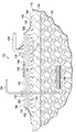
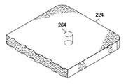
일부 구현예들에서, 드레싱 볼스터(124)는 존재할 수 있거나 존재할 수 없는 피하 전달 도관(134)의 존재를 수용하도록 사전-형성된다. 도 3a에서 도시된 바와 같이, 드레싱 볼스터(224)는 천공된 절단구멍(264) 또는 볼스터 재료의 천공된 원통과 같은 완화 영역의 형성에 의하여 피하 전달 도관을 선택적으로 수용하도록 사전-형성될 수 있다. 드레싱 볼스터를 통과하는 도관의 용이한 통과를 가능하게 하기 위하여, 볼스터 재료의 천공된 원통은 드레인이 적용되어야 할 경우에 드레싱 볼스터(224)로부터 손으로 제거될 수 있거나 천공될 수 있다. 또한, 근사적으로 임의의 바람직한 예측가능한 드레인 튜브 크기의 크기인 볼스터 재료의 일부가 손으로 제거될 수 있도록 볼스터 재료를 다양한 직경의 다중 절단구멍들로 천공하는 것이 바람직할 수 있다. In some implementations, the dressing bolster 124 is pre-formed to accommodate the presence of the
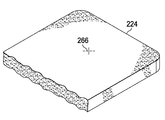
대안적으로, 드레싱 볼스터(224)에서 약간 더 변형이 용인되는 곳에서는, 드레싱 볼스터(224)가 드레인 튜브의 통과가 가능하도록 3b에 도시된 바와 같이 볼스터 재료로 제조된 단면-절단구멍(266)의 형태로 완화 영역을 가질 수 있다. 천공된 절단구멍(264)은 드레싱 볼스터(224)를 관통되는 도관 또는 튜브의 형태에 따른 임의의 다양한 천공된 형상 또는 크기일 수 있다. 드레싱 볼스터(224)가 도 2의 내부 편의층과 같은, 선택적인 편의층과 함께 조립되는 경우에는, 천공 또는 단면-절단구멍은 또한 드레싱 볼스터 재료에서 천공된 절단구멍(264) 또는 단면-절단구멍(266)을 상보하기 위하여 내부 편의층(142)에 형성될 수 있다. Alternatively, where slightly more deformation is acceptable in the dressing bolster 224, the
이제 도 4를 주로 참조하면, 완화 영역을 갖는 드레싱 볼스터(224)를 포함하는 상처 드레싱 조립체(222)가 도시된다. 상처 드레싱 조립체(222) 구성요소들은 피하 전달 도관이 드레싱 볼스터(224)를 관통하기 위하여 드레싱 볼스터 재료의 원통의 용이한 제거를 가능하게 하는 천공된 절단구멍(264) 또는 단면-절단구멍(266)(도 3b)을 구비할 수 있다. 그러한 구현예들에서, 천공된 절단구멍(264) 또는 단면-절단구멍(266)은 피하 전달 도관의 존재여부에 관계없이 유체 밀봉이 조직 부위에서 유지되도록 상처 드레싱 조립체의 오직 일부만을 관통하여 연장될 수 있다. 상처 드레싱 조립체는 제2 감압 인터페이스(232)와, (만약에 피하 전달 도관이 존재한다면), 피하 전달 도관의 경계에서 유체 밀봉을 형성하기 위한 제2 감압 인터페이스(232)를 포함한다. 제2 감압 인터페이스(232)는 조직 부위와 대기 환경 간의 오버-드레이프(226)에 의하여 제공되는 밀봉을 강화하도록 기능할 수 있다. 여기서, 제2 감압 인터페이스(232)는 또한 도관의 섹션이 제2 감압 인터페이스(232)를 관통하여 보내질 수 있게 하기 위한 구멍(268)을 포함한다.Referring now primarily to FIG. 4, a
이제 도 5를 주로 참조하면, 위에서 언급된 바와 같이 제2 감압 인터페이스(232)는 탄성중합체 성질들을 가지는 재료들, 즉, 탄성중합체를 사용하여 성형될 수 있다. 제2 감압 인터페이스(232)의 재료의 탄성은 도관 또는 피하 전달 도관(234)의 섹션이 구멍을(268)을 관통하도록 제2 감압 인터페이스(232)의 구멍(268)이 팽창할 수 있게 한다. 일 구현예에서, 구멍(268)은 제2 감압 인터페이스(232)를 관통하여 지나갈 수 있는 도관의 직경보다 약간 더 작은 직경을 가질 수 있다. 크기 결정에서 이러한 작은 겹침은 피하 전달 도관(234)이 제2 감압 인터페이스(232)를 관통하여 지나갈 경우에 구멍(268)이 작은 양의 변형을 겪도록 하는 인터페이스 끼워맞춤을 달성할 수 있다. Referring primarily to FIG. 5, as mentioned above, the second pressure
변형의 결과로, 제2 감압 인터페이스(232)의 탄성중합체 성질들(즉, 탄성)은 구멍(268)의 표면과 피하 전달 도관(234) 간의 반경방향 압축력(270)을 발생시킨다. 그럼으로써 반경방향 압축력(270)은 제2 감압 인터페이스(232)와 피하 전달 도관(234)의 경계선에서 유체 밀봉을 형성할 수 있고, 그럼으로써 조직 부위와 주위 환경 간의 압력 차이를 유지할 수 있다. 일부 경우에, 부가적인 재료들이 제2 감압 인터페이스(232) 및 피하 전달 도관(234)의 이러한 밀봉된 경계선을 형성하거나 강화시키는데 사용될 수 있다. 예를 들면, 접착제 또는 하나 이상의 가스켓들(예를 들어, 오링)이 유체 밀봉의 강도를 증가시키기 위하여 구멍(268)의 표면과 피하 전달 도관(234)의 외면 간에 설치될 수 있다.As a result of the deformation, the elastomeric properties (ie, elasticity) of the second pressure
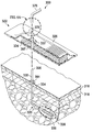
이제 도 6을 주로 참조하면, 선형 상처(미도시)를 갖는 조직 부위를 치료하기 위한 감압 시스템(300)의 다른 구현예가 제시된다. 감압 시스템(300)은 조직 부위(미도시)에 적용되도록 상처 드레싱 조립체(322) 내로 포함되는 제2 감압 인터페이스(332)를 포함한다. 조직 부위는 피하 전달 도관(334)의 제1 도관 세그먼트(335)에 근접한다. 일부 경우에, 주위 조직을 가능한 한 적게 방해하면서 피하 전달 도관(334)의 제1 도관 세그먼트(335)를 피하 조직(320)에 설치되어 유지될 수 있고 삽입된 도관 위로 상처 드레싱 조립체(322)를 적용할 수 있도록 하는 것은 바람직할 수 있다. 여기서, 피하 전달 도관(334)이 환자의 표피 또는 피부에서 나오는 환자의 표피의 점 근처에 위치된 선형 상처(미도시)에 감압을 전달하기 위하여 상처 드레싱 조립체(322)를 적용하기 위한 더욱 모듈화된 해결책이 도시된다.Referring now primarily to FIG. 6, another embodiment of a
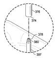
피하 전달 도관(334)은 환자 표피(316) 위로 단지 근거리(예를 들어, 약 10 센티미터)만큼 연장되고 예를 들어, 제2 세그먼트(376) 또는 어댑터(397)의 부가적인 섹션들에 실질적으로 연결되는 제1 도관 세그먼트(335)를 포함할 수 있다. 결합된 도관 세그먼트들(335, 397, 및 376)(또는 일부 구현예들에서, 335 및 376)은 수집된 유체들을 빼내는데 사용된다. 피하 전달 도관(334)의 제1 도관 세그먼트(335)는 환자에 설치되어 유지될 수 있고 크기가 정해질 수 있고, 다듬어질 수 있거나 그렇지 않으면 제1 도관 세그먼트(335)의 단부 부분(396)과 제2 도관 세그먼트(376)의 단부 부분(374) 간의 밀봉된 결합을 충분히 가능하게 하도록 표피(316)로부터 돌출되게 구성될 수 있다. 제2 도관 세그먼트(376)는 감압 소스 및 배수 수집 영역(미도시)에 유체적으로 연결된다. 피하 전달 도관(334)의 제2 도관 세그먼트(376)는 제1 도관 세그먼트(335)를 제거하지 않고 제거될 수 있거나 교체될 수 있다.
제1 도관 세그먼트(334)와 제2 도관 세그먼트(376) 간의 결합은 많은 방법으로 발생할 수 있다. 예를 들면, 효과적인 결합은 제2 도관 세그먼트(376)에 대하여 제1 도관 세그먼트(334)의 단부 부분(335) 간에 인터페이스 끼워맞춤을 제공함으로써 달성될 수 있다. 이러한 결합은 직접 결합이거나 어탭터(397)또는 중간 도관 세그먼트를 포함하는 커플러를 사용하여 만들어진 결합일 수 있다. 어댑터(397)가 사용되지 않는다면, 제1 도관 세그먼트는 상처 드레싱 조립체(322) 및 제2 감압 인터페이스(332)를 통하여 돌출하도록 크기가 정해질 수 있고, 제2 도관 세그먼트(376)의 단부 부분(또는 말단부)(374)은 제1 도관 세그먼트(335)의 단부 부분(396) 위에 꼭 맞도록 크기가 정해질 수 있다. 도관 세그먼트들(335 및 376)의 겹침은 액체-완전 밀봉을 형성한다.Coupling between the
어댑터(397)는 제1 도관 세그먼트(335) 및 제2 도관 세그먼트(376) 모두와 유체 밀봉을 형성하도록 적응된 테이퍼된 도관 단부들을 구비하는 커플러일 수 있다. 어댑터(397)를 제1 도관 세그먼트(335) 및 제2 도관 세그먼트(376)에 연결하는데 사용되는 임의의 밀봉 수단은 제1 도관 세그먼트(335)를 직접적으로 제2 도관 세그먼트(376)에 연결하는데 대안적으로 사용될 수 있다. 예를 들면, 제1 도관 세그먼트(335) 및 제2 도관 세그먼트(376)의 겹치는 부분들은 결합을 형성하기 위하여 공동으로 힘이 가해질 수 있다. 또한, 제2 도관 세그먼트(376)는 도 6a에 제시된 바와 같이, 어댑터(397)의 단부 세그먼트(378) 위에 홈이 파인 도관 세그먼트(380) 또는 제1 도관 세그먼트(335)의 홈이 파인 세그먼트를 수용할 수 있다. 도관 세그먼트들의 단부 부분들은 또한 밀봉을 형성하고 유지하는데 보조하기 위한 다른 물리적인 특징들을 포함할 수 있다. 예를 들면, 더 작은 도관 부분의 외면은 각지거나 또는 테이퍼될 수 있고 더 큰 직경 도관 부분의 내면은 마주보는 도관 세그먼트에 대하여 수용하고 밀봉하기 위한 상보적인 홈들 또는 테이퍼를 구비할 수 있다.
고정 부재(384)는 드레싱 조립체(322)의 적용 동안 주위 조직의 자극을 최소화하기 위하여 표피(316)에 대하여 제1 도관 세그먼트(335)를 고정하도록 선택적으로 포함될 수 있다. 그러한 바와 같이, 고정 부재(384)는 하부에 있는 진피에 대하여 자극 및 손상을 실질적으로 제거하거나 감소시키도록 습기에 대하여 매우 유연하거나 투과성 있는 저경도 재료일 수 있다. 고정 부재(384) 재료는 소결 고무 또는 실리콘 고분자 부재와 같은 다공성 재료일 수 있다. 고정 부재(384)는 접착제 또는 다른 부착 장치를 사용하여 표피(316)에 부착될 수 있다. 고정 부재(384)는 제1 도관 세그먼트(335)의 원치 않는 움직임을 방지하기 위하여 제1 도관 세그먼트(335)를 고정하는데 도움된다. 고정 부재(384)는 도 6에 도시된 바와 같이 링의 형상을 취할 수 있거나 플랜지 형상을 가질 수 있다. 그러한 배열에서, 고정 부재(384)는 중간 도관 세그먼트로서 기능할 수 있으면서 제1 도관 세그먼트(334)와 제2 도관 세그먼트(376) 간의 밀봉된 연결을 형성할 수 있거나, 단지 도관 세그먼트들(335 및 376)을 고정하는 관통 장치일 수 있다.Fixing
이제 도 7을 주로 참조하면, 선형 상처를 갖는 조직 부위를 치료하기 위한, 제2 감압 인터페이스(432)를 포함하는 다른 감압 시스템(400)이 제시된다. 상처 드레싱 조립체(422)는 많은 면에서 도 2의 상처 드레싱 조립체(122)와 유사하다. 그러나, 오버-드레이프(426)는 더 느슨하게 맞춰지고 제2 감압 인터페이스(432) 위에 형성될 수 있고 오링(486) 또는 클램프로 피하 전달 도관(434)에 대하여 고정될 수 있다. 제2 감압 인터페이스(432)는 인터페이스 본체(433)로부터 형성된 접속관(431)을 포함할 수 있다.Referring primarily to FIG. 7, another
이제 도 8을 주로 참조하면, 감압으로 조직 부위를 치료하는데 적용을 위한 상처 드레싱 조립체(522)의 일부분의 분해 사시도가 제시된다. 조직 부위는 피하 조직 부위, 선형 상처, 영역 상처, 또는 다른 상처 또는 이식편일 수 있다. 도 8에서 제시된 상처 드레싱 조립체(522)는 사전-배치 상태이며 분해도로 도시된다. 상처 드레싱 조립체(522)는 대부분 면에서 도 1 및 도 2의 상처 드레싱 조립체(122)와 유사하다. 상응하는 부분들을 표시하기 위하여, 참조 부호들은 100에 의하여 색인되었고 더 이상 언급되지 않을 수 있다.Referring now primarily to FIG. 8, an exploded perspective view of a portion of a
상처 드레싱 조립체(522)는 차례로 드레싱 볼스터(524)의 표면에 대하여 횡방향 및 종방향 모두에 유연성 노치들(544)을 포함할 수 있는 드레싱 볼스터(524)를 포함한다. 드레싱 볼스터(524)의 제1 측면(548)은 제1 드레이프 부분(560) 및 제2 드레이프 부분(562)를 포함할 수 있는 오버-드레이프(526)에 의하여 덮일 수 있다. 제1 드레이프 부분(560)은 주름들(546) 및 드레이프 구멍(559)를 포함한다. 제2 드레이프 부분(562)은 환자의 표피에 직접적으로 적용되도록 드레싱 볼스터(524) 또는 내부 편의층(542)의 적어도 일부분에 대한 개구를 제공하는 치료-영역 구멍(588)과 함께 형성된다. 제2 드레이프 부분(562)은 제1 측면(587)을 구비하며 제1 측면(587)의 일부분 위에 적용되는 접착제(589)를 구비한다. 접착제(589)는 조립 중에 제2 드레이프 부분(562)에 대하여 드레싱 볼스터(524)를 (또는 존재한다면 내부 편의층(542)) 지지하기 위하여 주로 제조 중에 사용되며, 또한 사용 중에 드레싱 볼스터(524)를 지지하는데 도움이 되도록 사용된다. 접착제(589)에 대하여 드레싱 볼스터(524) 또는 내부 편의층(542)를 적용하기 전에, 접착제(589)는 중심 해제가능한 부재(585)에 의하여 덮인다. 제1 측면(587) 위의 접착제(589)의 아웃보드는 배치 중에 오버-드레이프(526)에 강성을 제공하는 해제가능한 부재들(583)이다.The
제2 드레이프 부분(562)의 제2 내향 측면(명시적으로 도시되지 않으나 제1 측면(587)의 반대편)은 접착제로 덮일 수 있다. 사전-배치 상태에서, 이러한 접착제는 밑면 해제 부재(590) 및 측면 해제 부재(583)에 의하여 덮인다.A second inward side of the second drape portion 562 (not explicitly shown but opposite of the first side 587) may be covered with an adhesive. In the pre-positioned state, this adhesive is covered by the
일단 조립되면, 상처 드레싱 조립체(522)는 도 1의 드레싱 조립체(122)와 유사할 수 있다. 사용 및 설계는 다를 수 있으나, 예시적인 일 구현예에서는, 상처 드레싱 조립체(522)는 아래에 설명된 바와 같이 배치될 수 있다. 피하 전달 도관(미도시)은 환자 내로 삽입될 수 있고 이어서 말단부는 제2 측면으로부터 제1 측면으로 상처 드레싱 조립체(522)를 관통하여 배치될 수 있다. 일 구현예에서, 피하 전달 도관은 편의층(542)에서 (존재한다면) 사전 형성된 절단구멍들(566)을 관통하여 그리고 선택적으로 드레싱 볼스터(524)를 관통하여 밀려진다. Once assembled, wound dressing
밑면 해제 라이너(590)가 제거되고 제2 드레이프 부분(562)의 제2 내향 측면 위에 노출된 접착제가 일단부에서 시작되는 환자의 표피의 일부분에 대하여 배치되고 상처 드레싱 조립체(522)가 선형 상처 위에 배치될 수 있다. 제2 드레이프 부분(562)을 매끄럽게 적용하고 난 후에, 측면 해제 부재들(583)은 제거된다. 오버-드레이프(526)의 제1 측면(587) 위의 해제 부재들(581)이 제거된다. 제1 감압 인터페이스(528)는 제1 드레이프 부분(560)의 드레이프 구멍(559)에 연결된다. 제2 감압 인터페이스(532)는 또한 드레인의 존재를 수용하기 위한 드레싱 볼스터(524) 및 (존재한다면) 내부 편의층(542에 만들어진 사전-형성된 절단구멍들(566)의 중심과 동축인 위치에서 (만약에 제조 중에 이미 적용되지 않았다면)드레이프에 부착될 수 있다. 중심 해제 부재(585)는 제조 중에 제거되었을 것이다.The
사용자 또는 치료 제공자는 상처 드레싱 조립체(522)의 범위 내에 드레인 또는 다른 피하 전달 튜브를 구비한 제2 감압 인터페이스(532)를 포함하는 상처 드레싱 조립체(522)를 적용할 수 있다. 일 구현예에서, 제2 감압 인터페이스는 제조 중에 상처 드레싱 조립체에 설치된다. 다른 구현예에서, 제2 감압 인터페이스(532)는 사용시에 부가될 수 있는 별도 품목이다. 예를 들면, 드레인 튜브는 외과적인 상처의 단부로부터 돌출될 수 있고 그러므로 사용자는 제2 감압 인터페이스(532)가 필요하다고 인지하여 제2 감압 인터페이스(532)를 적용한다.The user or treatment provider may apply a
일 구현예의 적용에서, 상처 드레싱 조립체를 선택한 후에, 사용자는 드레싱 볼스터에서 사전-형성된 절단구멍들이 드레인의 피하 전달 도관과 정렬되도록 상처 드레싱 조립체(522)의 배향한다. 이어서 사용자는 도관을 사용자가 오버-드레이프(526)의 저항을 느낄 때까지 드레싱 볼스터를 통하여 도관을 누른다. 사용자는 몰드 감압 인터페이스에 힘을 가하여 도관을 밀어 임계력을 받을 때 찢어지는, 드레이프를 관통한다. 임계력을 가하기 위하여, 감압 인터페이스는 사용자가 인터페이스를 형성하는 재료를 파지하여 도관에 대하여 누를 수 있도록 충분한 크기일 필요가 있을 수 있다. 예를 들면, 제2 감압 인터페이스는 도관이 통과하는 구멍을 지나 반경방향으로 적어도 1 센티미터에 대하여 연장될 필요가 있을 수 있다. 이어서 사용자는 도관을 용기에 연결하기 전에 상처 드레싱 조립체(522)의 배치가 가능하도록 상처 드레싱 조립체(522)를 통하여 도관을 충분한 양으로 당긴다. 이러한 적용 방법은 도관 및 상처 드레싱 조립체(522)의 경계선에서 유체 밀봉을 형성하기 위하여 도관에 대하여 반경방향 압축을 받는 제2 감압 인터페이스 및 찢어진 오버-드레이프 모두를 발생시켜야 한다.In application of one embodiment, after selecting the wound dressing assembly, the user orients the
유사한 일 구현예에서, 제2 감압 인터페이스(532)는 배치 시에 부가될 수 있다. 피하 전달 도관이 상처 부위 근처에 있는 경우에, 도관은 사전-형성된 절단구멍(566) 또는 유사한 새롭게 형성된 절단구멍들을 통하여 통과될 수 있다. 유사하게, 도관의 말단부는 천공되도록 설계된 오버-드레이프(526)의 일부분을 통하거나 드레이프에 새롭게 형성된 절개를 통하여 가압될 수 있다. 제2 감압 인터페이스(532)는 피하 전달 도관의 말단부 위에 배치될 수 있고, 피하 전달 도관 위로 미끄러질 수 있고, 오버-드레이프(526)의 외부 표면에 부착될 수 있다. 이어서 피하 전달 도관의 말단부는 감압 소스에 연결될 수 있다. 감압 전달 도관은 제1 감압 인터페이스(528)를 감압 소스에 연결할 수 있다. 감압 소스는 양 인터페이스 모두에 대하여 동일할 수 있거나, 상이한 감압 소스들이 필요한 만큼 각각의 인터페이스에 부착될 수 있다.In a similar implementation, the
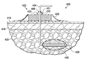
이제 주로 도 9를 참조하면, 대안적인 형상을 갖는 드레싱 조립체(622)가 도시된다. 드레싱 조립체(622)는 본체의 상이한 부분들에 감압을 적용하도록 크기가 정해지고 구성될 수 있으며 그에 따라서 크기 및 형상이 변할 수 있다. 유사하게, 드레싱 조립체(622)의 크기는 예상되는 상처 크기에 따라서 변할 수 있다. 여기서, 드레싱 볼스터(624), 제1 감압 인터페이스(628), 제1 감압 도관(630), 제2 감압 인터페이스(632), 및 피하 전달 도관(634)을 포함하여 위에서 설명된 많은 특징들 및 속성들을 갖는 드레싱 조립체(622)가 도시된다.Referring now primarily to FIG. 9, a dressing
드레인 튜브를 위한 통로를 용이하게 하는 것 이외에, 제2 감압 인터페이스(632)는 또한 부가적인 치료 및 진단 적용을 상처 부위에 전달하도록 기능할 수 있다. 예를 들어, 드레인을 수용하는 것 이외에, 제2 피하 전달 도관(634)은 외부 진단 장치에 부착된 작은 전선 센서를 이용하여 상처 부위를 감시하는데 사용될 수 있다. 유사하게, 제2 감압 인터페이스(632)는 가까이 위치된 피하 상처 부위에서 감압 치료요법의 적용을 가능하게 할 수 있다. 그러한 적용예에서, 피하 전달 도관(634)은 매니폴드 재료와 피하 전달 도관이 유체적으로 연결될 수 있는, 골 손상과 같은 피하 조직 부위에 매니폴드 재료를 전달하는데 사용될 수 있다. In addition to facilitating the passageway for the drain tube, the
매니폴드 재료를 전달하고 난 후에, 피하 전달 튜브(634)는 감압을 뼈 또는 척수 외상과 같은 피하 조직 부위에 전달하기 위하여 감압 소스(미도시)에 연결될 수 있다. 이처럼, 제2 감압 인터페이스(632)의 추가는 단일 상처 드레싱 조립체 및 감압 소스를 사용하여 두 개의 구별되는 조직 부위들에 감압 치료요법의 전달을 제공한다.After delivering the manifold material,
본 발명 및 본 발명의 장점들이 특정한 예시적이고, 비제한적인 구현예들의 맥락에서 개시되었지만, 다양한 변화, 대체, 치환, 및 개조들이 첨부되는 청구항들에 의하여 정의되는 바와 같은 본 발명의 범주로부터 벗어나지 않으면서 제작될 수 있다는 것이 이해되어야 한다. 임의의 일 구현예에 연결되어 설명된 임의의 특징 또한 임의의 다른 구현예에 적용가능할 수 있다는 것이 이해될 것이다.Although the invention and its advantages have been disclosed in the context of certain illustrative and non-limiting embodiments, various changes, substitutions, substitutions, and alterations will be made without departing from the scope of the invention as defined by the appended claims. It should be understood that it can be manufactured. It will be appreciated that any feature described in connection with any one embodiment may also be applicable to any other embodiment.
위에서 설명된 이익들 및 장점들은 일 구현예에 관계될 수 있거나 몇몇 구현예들에 관계될 수 있다는 것이 이해될 것이다. 또한, "하나의(an)" 항목에 대한 언급은 그러한 항목들의 하나 이상을 언급한다는 것도 이해될 것이다.It will be appreciated that the benefits and advantages described above may relate to one implementation or may relate to some implementations. It will also be understood that reference to "an" item refers to one or more of such items.
여기서 설명된 방법들의 단계들은 적합한 임의의 순서나, 적절한 경우 동시에 수행될 수 있다.The steps of the methods described herein may be performed in any suitable order, or simultaneously if appropriate.
적절한 경우, 위에서 설명된 임의의 실시예들의 양태들은 설명된 임의의 다른 실시예들의 양태들과 결합할 수 있어서 비슷하거나 상이한 특성들을 갖는 다른 실시예들을 형성하고 동일하거나 상이한 문제들을 해결할 수 있다.Where appropriate, aspects of any of the embodiments described above can be combined with aspects of any of the other embodiments described above to form other embodiments having similar or different characteristics and solve the same or different problems.
위의 바람직한 구현예들의 설명은 예시로서만 주어지며, 다양한 변형들이 통상의 기술자에 의하여 제작될 수 있다는 것이 이해될 것이다. 위의 상세한 설명, 실시예들 및 데이터는 본 발명의 예시적인 구현예들의 구조 및 용도의 완전한 설명을 제공한다. 본 발명의 다양한 구현예들이 특정한 정도의 상세함이나 하나 이상의 개별적인 구현예들을 참조하여 설명되었지만, 통상의 기술자는 본 청구항들의 범주로부터 벗어나지 않으면서 개시된 구현예들에 대하여 많은 개조를 할 수 있다.It will be appreciated that the description of the above preferred embodiments is given by way of example only, and that various modifications may be made by those skilled in the art. The above detailed description, examples, and data provide a complete description of the structure and use of exemplary embodiments of the present invention. While various embodiments of the present invention have been described with reference to a certain degree of detail or one or more individual embodiments, those skilled in the art may make many modifications to the disclosed embodiments without departing from the scope of the claims.
Claims (22)
의료 볼스터 재료로부터 형성된 드레싱 볼스터로서 환자의 표피 위에 배치되고 상기 선형 상처를 덮도록 크기가 정해진, 드레싱 볼스터;
상기 드레싱 볼스터 및 상기 환자의 표피의 일부분 위에 유체 밀봉을 제공하기 위한 오버-드레이프;
감압 소스;
상기 드레싱 볼스터 및 상기 감압 소스에 유체적으로 연결되고 감압을 상기 드레싱 볼스터에 전달하기 위한 제1 감압 인터페이스;
상기 감압 소스 및 상기 제1 감압 인터페이스를 유체적으로 연결하기 위한 감압 전달 도관; 및
상기 오버-드레이프에 연결되고 피하 전달 도관을 수용하고 상기 피하 전달 도관에 대하여 유체 밀봉을 형성하도록 크기가 정해지고 구성되는 제2 감압 인터페이스를 포함하는 감압 시스템.A decompression system for treating a tissue site with a linear wound,
A dressing bolster formed from a medical bolster material, the dressing bolster disposed on the epidermis of the patient and sized to cover the linear wound;
An over-drape for providing a fluid seal over the dressing bolster and a portion of the epidermis of the patient;
Reduced pressure source;
A first pressure reducing interface fluidly connected to the dressing bolster and the pressure reducing source and for delivering a reduced pressure to the dressing bolster;
A reduced pressure delivery conduit for fluidly connecting said reduced pressure source and said first reduced pressure interface; And
A second pressure reducing interface connected to the over-drape and sized and configured to receive a subcutaneous delivery conduit and form a fluid seal with respect to the subcutaneous delivery conduit.
상기 피하 전달 도관을 상기 드레싱 볼스터 및 상기 오버-드레이프를 관통하여 전달하기 위한 사전-형성된 경로를 더 포함하는 감압 시스템.The method of claim 1,
And a pre-formed pathway for delivering said subcutaneous delivery conduit through said dressing bolster and said over-drape.
상기 제2 감압 인터페이스는 내경(D1)을 갖는 구멍을 구비하는 접속관을 포함하며, 상기 피하 전달 도관은 외경(D2)을 갖고, D1<D2이며 이에 의하여 상기 유체 밀봉이 형성되는 감압 시스템.3. The method according to claim 1 or 2,
Said second pressure reducing interface comprises a conduit having a hole having an inner diameter (D1), said subcutaneous delivery conduit having an outer diameter (D2), wherein D1 <D2, whereby said fluid seal is formed.
제1 표면 및 제2 내향표면을 구비하고 치료 영역 구멍 내에 형성된 내층을 더 포함하되, 상기 내층의 상기 제1 표면은 상기 드레싱 볼스터의 상기 제2 표면에 적어도 부분적으로 연결되고, 상기 내층은 상기 피하 전달 도관을 수용하도록 사전-절단되는 감압 시스템. The dressing bolster of claim 1, wherein the dressing bolster has a first surface and a second inward surface substantially disposed over the epidermis of the patient and substantially sized to cover the linear wound;
And further comprising an inner layer having a first surface and a second inward surface and formed in the treatment area aperture, wherein the first surface of the inner layer is at least partially connected to the second surface of the dressing bolster, the inner layer being subcutaneous A pressure reducing system pre-cut to receive a delivery conduit.
상기 제2 감압 인터페이스는 유연한(pliable) 오버-드레이프 및 하나 이상의 오링(o-ring)을 포함하는 감압 시스템.The method according to any one of claims 1, 2, and 4,
The second pressure reducing interface includes a pliable over-drape and one or more o-rings.
상기 조직 부위는 제1 조직 부위이고, 상기 감압 전달 도관은 제1 감압 전달 도관이며, 상기 감압 시스템은
통로 및 상기 피하 전달 도관에 삽입되고 제2 조직 부위에 인접하게 배치되도록 구성된 말단부를 구비하는 매니폴드 전달 튜브;
유동가능한 재료로서, 상기 유동가능한 재료가 상기 제2 조직 부위와 유체 연통하는 복수의 유동 채널들을 구비하는 매니폴드를 생성하기 위하여 상기 제2 조직 부위에 인접한 공동을 채울 수 있도록 상기 제2 조직 부위에 상기 매니폴드 전달 튜브를 통하여 전달가능한, 유동가능한 재료; 및
상기 매니폴드의 상기 복수의 유동 채널과 유체 연통 가능한 제2 감압 전달 도관을 더 포함하는 것인 감압 시스템.The method according to any one of claims 1 to 5,
The tissue site is a first tissue site, the reduced pressure delivery conduit is a first reduced pressure delivery conduit, and the reduced pressure system is
A manifold delivery tube having a passageway and a distal end configured to be inserted into the subcutaneous delivery conduit and disposed adjacent to the second tissue site;
A flowable material, wherein the flowable material is capable of filling a cavity adjacent to the second tissue site to create a manifold having a plurality of flow channels in fluid communication with the second tissue site. A flowable material transferable through the manifold delivery tube; And
And a second reduced pressure delivery conduit in fluid communication with the plurality of flow channels of the manifold.
상기 매니폴드 전달 튜브 및 상기 제2 감압 전달 도관은 동일한 튜브인 감압 시스템.The method according to claim 6,
Said manifold delivery tube and said second reduced pressure delivery conduit being the same tube.
상기 매니폴드는 생체흡수성인 감압 시스템.The method according to claim 6,
And the manifold is bioabsorbable.
상기 피하 전달 도관은 제1 도관 세그먼트 및 제2 도관 세그먼트를 포함하고;
상기 제2 감압 인터페이스는
상기 제1 도관 세그먼트의 단부를 수용하고;
상기 제2 도관 세그먼트의 단부를 수용하고;
상기 제1 도관 세그먼트와 상기 제2 도관 세그먼트 간에 유체 연결을 유지하도록 크기가 정해지고 구성된 어댑터를 포함하는 것인 감압 시스템.The method according to any one of claims 1 to 8,
The subcutaneous delivery conduit comprises a first conduit segment and a second conduit segment;
The second decompression interface is
Receive an end of the first conduit segment;
Receive an end of the second conduit segment;
And an adapter sized and configured to maintain a fluid connection between the first conduit segment and the second conduit segment.
상기 제2 감압 인터페이스는 성형 플라스틱 원통 부분을 포함하며, 상기 성형 플라스틱 원통 부분은
제1 표면;
제2 표면;
외부 둘레;
상기 성형 플라스틱 원통 부분 위에 형성된 구멍을 구비하되,
상기 구멍은 도관을 수용하고 상기 도관의 상기 외부 둘레에 대하여 반경방향 압축력을 발생시키도록 크기가 정해지고;
상기 제2 표면은 상기 제2 표면과 감압 상처 드레싱 조립체의 오버-드레이프 간에 유체 밀봉을 형성하기 위한 접착제를 포함하는 것인 감압 시스템.The method according to any one of claims 1 to 8,
The second pressure sensitive interface includes a molded plastic cylindrical portion, the molded plastic cylindrical portion
First surface;
Second surface;
Outer perimeter;
A hole formed on the molded plastic cylindrical part,
The aperture is sized to receive a conduit and to generate a radial compressive force about the outer perimeter of the conduit;
And the second surface comprises an adhesive to form a fluid seal between the second surface and the over-drape of the pressure sensitive wound dressing assembly.
상기 성형 플라스틱 원통 부분은 상기 도관으로 상기 감압 상처 드레싱 조립체의 상기 오버-드레이프를 천공하는데 요구되는 힘의 양과 동등한 손-발생되는 힘을 전달하도록 크기가 정해지는 감압 시스템.11. The method of claim 10,
And the molded plastic cylindrical portion is sized to deliver a hand-generated force equal to the amount of force required to puncture the over-drape of the reduced pressure wound dressing assembly to the conduit.
환자의 표피 위에 배치되고 상기 선형 상처를 덮도록 크기가 정해진 제1 표면 및 제2 내향 표면을 구비하는 드레싱 볼스터;
상기 드레싱 볼스터 및 상기 환자의 표피의 일부분 위에 유체 밀봉을 제공하기 위한 오버-드레이프;
감압 공급 도관을 수용하도록 작동가능한 제1 감압 인터페이스;
제1 표면 및 제2 내향 표면을 구비하며, 치료-영역 구멍 내에 형성된 내층으로서, 상기 내층의 상기 제1 표면은 상기 드레싱 볼스터의 상기 제2 표면에 적어도 부분적으로 연결되는 것인, 내층; 및
제2 감압 인터페이스를 포함하되, 상기 제2 감압 인터페이스는,
구멍이 형성되고 제1 측면 및 제2 환자-방향 측면을 구비하는 인터페이스 본체를 포함하되,
상기 구멍은 피하 전달 도관을 수용하고 피하 전달 도관과 유체 밀봉을 형성하도록 크기가 정해지고,
상기 제2 감압 인터페이스는 상기 피하 전달 도관이 피하 조직 부위로부터 상기 구멍을 통하여 외부 부위로 통과할 수 있도록 구성되며 상기 피하 전달 도관은 상기 제2 인터페이스로 상기 치료-영역 구멍 및 상기 드레싱 볼스터를 관통하여 전달되는 것인, 상처 드레싱 조립체.A wound dressing assembly for treating a tissue site having a linear wound, comprising:
A dressing bolster disposed over the epidermis of the patient and having a first surface and a second inward surface sized to cover the linear wound;
An over-drape for providing a fluid seal over the dressing bolster and a portion of the epidermis of the patient;
A first pressure reducing interface operable to receive the pressure reducing supply conduit;
An inner layer having a first surface and a second inward surface, wherein the first layer of the inner layer is at least partially connected to the second surface of the dressing bolster; And
A second decompression interface, wherein the second decompression interface,
An interface body formed with a hole and having a first side and a second patient-direction side,
The aperture is sized to receive the subcutaneous delivery conduit and form a fluid seal with the subcutaneous delivery conduit,
The second decompression interface is configured to allow the subcutaneous delivery conduit to pass from the subcutaneous tissue site through the aperture to the external site and the subcutaneous delivery conduit passes through the treatment-area hole and the dressing bolster to the second interface. What is delivered, wound dressing assembly.
드레싱 볼스터 및 내층은 상기 피하 전달 도관이 상기 치료-영역 구멍으로부터 상기 제2 감압 인터페이스로 통과할 수 있도록 적어도 부분적으로 사전-절단되는 상처 드레싱 조립체.The method of claim 12,
A dressing bolster and an inner layer are at least partially pre-cut such that the subcutaneous delivery conduit can pass from the treatment-area aperture to the second decompression interface.
상기 제2 감압 인터페이스는 유연한 오버-드레이프 및 하나 이상의 오링(o-ring)을 포함하는 상처 드레싱 조립체.The method according to claim 12 or 13,
The second pressure reducing interface includes a flexible over-drape and one or more o-rings.
상처 드레싱 조립체를 상기 조직 부위에 적용하는 단계로서, 상기 상처 드레싱 조립체는,
환자의 표피 위에 배치되기 위하여 성형되고 실질적으로 상기 선형 상처를 덮도록 크기가 정해지는 의료 볼스터 재료로부터 형성된 드레싱 볼스터,
상기 드레싱 볼스터 및 상기 환자의 표피의 일부분 위에 유체 밀봉을 제공하기 위한 오버-드레이프,
감압을 상기 드레싱 볼스터에 전달하기 위하여 상기 드레싱 볼스터에 유체적으로 연결된 제1 감압 인터페이스, 및
상기 오버-드레이프에 연결된 제2 감압 인터페이스를 포함하되, 상기 제2 감압 인터페이스는 피하 전달 도관을 수용하고 상기 피하 전달 도관과 상기 상처 드레싱 조립체 간의 유체 밀봉을 형성하도록 크기가 정해지고 구성되는 것인 제2 감압 인터페이스를 포함하는 것인, 단계;
감압 전달 도관을 감압 소스 및 상기 제1 감압 인터페이스로 유체적으로 연결하는 단계;
감압을 상기 감압 전달 도관으로 전달하는 단계;
피하 전달 도관을 상기 제2 인터페이스에 유체적으로 연결하는 단계; 및
감압을 상기 피하 전달 도관에 전달하는 단계를 포함하는 선형 상처를 갖는 조직 부위를 치료하는 방법.As a method for treating a tissue site having a linear wound,
Applying the wound dressing assembly to the tissue site, wherein the wound dressing assembly comprises:
A dressing bolster formed from a medical bolster material shaped to be placed over the epidermis of a patient and sized to substantially cover the linear wound,
An over-drape for providing a fluid seal over the dressing bolster and a portion of the epidermis of the patient,
A first pressure reducing interface fluidly connected to the dressing bolster for delivering a reduced pressure to the dressing bolster, and
A second decompression interface coupled to the over-drape, wherein the second decompression interface is sized and configured to receive a subcutaneous delivery conduit and form a fluid seal between the subcutaneous delivery conduit and the wound dressing assembly; 2 comprising a decompression interface;
Fluidly connecting a reduced pressure delivery conduit to a reduced pressure source and said first reduced pressure interface;
Delivering a reduced pressure to the reduced pressure delivery conduit;
Fluidly connecting a subcutaneous delivery conduit to the second interface; And
Delivering a decompression to said subcutaneous delivery conduit.
상기 드레싱 볼스터는 상기 피하 전달 도관을 수용하도록 사전-절단되는 선형 상처를 갖는 조직 부위를 치료하는 방법16. The method of claim 15,
Wherein the dressing bolster treats a tissue site having a linear wound that is pre-cut to receive the subcutaneous delivery conduit.
상기 조직 부위는 제1 조직 부위이며,
매니폴드 전달 튜브를 상기 제2 감압 인터페이스에 연결하는 단계로서, 상기 매니폴드 전달 튜브는 통로 및 말단부를 구비하며, 상기 말단부는 상기 피하 전달 도관으로 삽입되고 제2 조직 부위에 인접하게 배치되도록 구성되는 것인 단계;
유동가능한 생체흡수성 재료가 상기 제2 조직 부위와 유체 연통하는 복수의 유동 채널들을 구비하는 매니폴드를 생성하기 위하여 상기 제2 조직 부위에 인접한 공동을 채울 수 있도록 상기 제2 조직 부위에 상기 매니폴드 전달 튜브를 통하여 유동가능하고 생체흡수성 재료를 전달하는 단계;
감압 전달 도관을 상기 제2 전압 인터페이스로 연결하는 단계로서, 상기 감압 전달 도관은 상기 매니폴드의 상기 복수의 유동 채널들과 유체 연통할 수 있는 것인, 단계; 및
상기 제2 조직 부위에 감압을 적용하는 단계를 더 포함하는 선형 상처를 갖는 조직 부위를 치료하는 방법.17. The method according to claim 15 or 16,
The tissue site is a first tissue site,
Connecting a manifold delivery tube to the second pressure reducing interface, the manifold delivery tube having a passageway and a distal end, the distal end being configured to be inserted into the subcutaneous delivery conduit and disposed adjacent to a second tissue site Step;
Delivering the manifold to the second tissue site such that the flowable bioabsorbable material can fill a cavity adjacent to the second tissue site to create a manifold having a plurality of flow channels in fluid communication with the second tissue site. Delivering a flowable and bioabsorbable material through the tube;
Connecting a decompression delivery conduit to the second voltage interface, wherein the decompression delivery conduit is in fluid communication with the plurality of flow channels of the manifold; And
And applying a decompression to the second tissue site.
상기 매니폴드 전달 튜브 및 상기 감압 전달 도관은 동일한 튜브인 선형 상처를 갖는 조직 부위를 치료하는 방법.18. The method of claim 17,
And the manifold delivery tube and the reduced pressure delivery conduit are the same tube.
의료 볼스터 재료로부터 형성되고, 환자의 표피 위에 배치되고 실질적으로 선형 상처를 덮도록 크기가 정해지는 드레싱 볼스터를 제공하는 단계;
상기 드레싱 볼스터 및 상기 환자의 표피의 일부분 위에 유체 밀봉을 제공하기 위한 오버-드레이프를 제공하는 단계;
감압 소스를 제공하는 단계;
감압을 상기 드레싱 볼스터에 전달하기 위한 제1 감압 인터페이스를 제공하는 단계;
제2 감압 인터페이스를 제공하는 단계; 및
상기 제2 감압 인터페이스를 상기 오버-드레이프에 연결하는 단계로서, 상기 제2 감압 인터페이스는 피하 전달 도관을 수용하고 그 사이에 유체 밀봉을 형성하도록 크기가 정해지고 구성되는 것인 단계를 포함하는 상처 드레싱 조립체를 제조하는 방법.A method of making a wound dressing assembly for treating a damaged subcutaneous damaged tissue, the method comprising:
Providing a dressing bolster formed from the medical bolster material and sized to cover a substantially linear wound and disposed over the epidermis of the patient;
Providing an over-drape for providing a fluid seal over the dressing bolster and a portion of the epidermis of the patient;
Providing a decompression source;
Providing a first pressure reducing interface for delivering a reduced pressure to the dressing bolster;
Providing a second decompression interface; And
Connecting the second pressure reducing interface to the over-drape, wherein the second pressure reducing interface is sized and configured to receive a subcutaneous delivery conduit and form a fluid seal therebetween. A method of making an assembly.
상기 드레싱 볼스터는 상기 환자의 표피 위에 배치하고 실질적으로 상기 선형 상처를 덮도록 크기가 정해진 제1 표면 및 제2 내향 표면을 구비하고,
제1 표면 및 제2 내향 표면을 구비하며, 치료-영역 구멍 내에 형성된 내층을 제공하는 단계로서,
상기 내층의 상기 제1 표면은 상기 드레싱 볼스터의 상기 제2 표면에 적어도 부분적으로 연결되고;
상기 내층은 상기 피하 전달 도관을 수용하도록 사전-절단되는 것인 단계를 더 포함하는 상처 드레싱 조립체를 제조하는 방법.20. The method of claim 19,
The dressing bolster has a first surface and a second inward surface sized to place on the epidermis of the patient and substantially cover the linear wound,
Providing an inner layer having a first surface and a second inward surface, the inner layer formed in the treatment-area aperture,
The first surface of the inner layer is at least partially connected to the second surface of the dressing bolster;
And wherein the inner layer is pre-cut to receive the subcutaneous delivery conduit.
Applications Claiming Priority (3)
| Application Number | Priority Date | Filing Date | Title |
|---|---|---|---|
| US201161514801P | 2011-08-03 | 2011-08-03 | |
| US61/514,801 | 2011-08-03 | ||
| PCT/US2012/047742 WO2013019438A1 (en) | 2011-08-03 | 2012-07-20 | Reduced-pressure wound dressings |
Publications (1)
| Publication Number | Publication Date |
|---|---|
| KR20140049582A true KR20140049582A (en) | 2014-04-25 |
Family
ID=46584415
Family Applications (1)
| Application Number | Title | Priority Date | Filing Date |
|---|---|---|---|
| KR1020147005501A KR20140049582A (en) | 2011-08-03 | 2012-07-20 | Reduced-pressure wound dressings |
Country Status (10)
| Country | Link |
|---|---|
| US (3) | US8992510B2 (en) |
| EP (2) | EP2944337B1 (en) |
| JP (1) | JP6189840B2 (en) |
| KR (1) | KR20140049582A (en) |
| CN (1) | CN103732268B (en) |
| AU (1) | AU2012290520B2 (en) |
| BR (1) | BR112014002229A2 (en) |
| CA (1) | CA2841860C (en) |
| RU (1) | RU2014100845A (en) |
| WO (1) | WO2013019438A1 (en) |
Families Citing this family (31)
| Publication number | Priority date | Publication date | Assignee | Title |
|---|---|---|---|---|
| US11298453B2 (en) | 2003-10-28 | 2022-04-12 | Smith & Nephew Plc | Apparatus and method for wound cleansing with actives |
| GB0508531D0 (en) | 2005-04-27 | 2005-06-01 | Smith & Nephew | Sai with ultrasound |
| GB0723872D0 (en) | 2007-12-06 | 2008-01-16 | Smith & Nephew | Apparatus for topical negative pressure therapy |
| US8298200B2 (en) | 2009-06-01 | 2012-10-30 | Tyco Healthcare Group Lp | System for providing continual drainage in negative pressure wound therapy |
| WO2010017437A1 (en) | 2008-08-08 | 2010-02-11 | Tyco Healthcare Group Lp | Wound dressing of continuous fibers |
| US20100324516A1 (en) | 2009-06-18 | 2010-12-23 | Tyco Healthcare Group Lp | Apparatus for Vacuum Bridging and/or Exudate Collection |
| JP5881735B2 (en) | 2010-12-22 | 2016-03-09 | スミス アンド ネフュー インコーポレーテッド | Apparatus and method for negative pressure wound therapy |
| EP2723286B2 (en) | 2011-06-24 | 2021-10-13 | KCI Licensing, Inc. | Reduced-pressure dressings employing tissue-fixation elements |
| EP2944337B1 (en) * | 2011-08-03 | 2021-03-24 | 3M Innovative Properties Company | Reduced-pressure wound dressings |
| USD733896S1 (en) | 2012-05-04 | 2015-07-07 | Genadyne Biotechnologies, Inc. | Abdominal dressing |
| EP3354293B1 (en) | 2012-05-23 | 2019-12-11 | Smith & Nephew plc | Apparatuses for negative pressure wound therapy |
| HUE033329T2 (en) | 2012-08-01 | 2017-11-28 | Smith & Nephew | Wound dressing |
| CN104661626B (en) | 2012-08-01 | 2018-04-06 | 史密夫及内修公开有限公司 | Wound dressing |
| JP6534931B2 (en) * | 2012-09-20 | 2019-06-26 | ローマン ウント ラウシェル ゲゼルシャフト ミット ベシュレンクテル ハフツング | Negative pressure therapeutic device and film for manufacturing negative pressure therapeutic device |
| US10085892B2 (en) | 2013-03-07 | 2018-10-02 | Life Sciences Llc | Apparatus and method for wound infection prevention |
| CN105188795B (en) | 2013-05-10 | 2018-07-31 | 史密夫及内修公开有限公司 | For rinsing and the fluid connection of suction wound |
| US10226566B2 (en) | 2014-04-23 | 2019-03-12 | Genadyne Biotechnologies, Inc. | System and process for removing bodily fluids from a body opening |
| CN106413594B (en) * | 2014-05-09 | 2020-07-31 | 凯希特许有限公司 | Destructive dressing for use with negative pressure and fluid instillation |
| WO2016040520A1 (en) * | 2014-09-10 | 2016-03-17 | Kci Licensing, Inc. | Therapy apparatus with integrated fluid conductors and noise attenuation |
| CA2983252C (en) * | 2015-05-01 | 2024-02-13 | Carl Linden DAMBKOWSKI | Systems and methods for protecting umbilical stumps |
| US10076594B2 (en) | 2015-05-18 | 2018-09-18 | Smith & Nephew Plc | Fluidic connector for negative pressure wound therapy |
| AU2017256692B2 (en) * | 2016-04-26 | 2022-03-03 | Smith & Nephew Plc | Wound dressings and methods of use with integrated negative pressure source having a fluid ingress inhibition component |
| US10046095B1 (en) * | 2017-04-04 | 2018-08-14 | Aatru Medical, LLC | Wound therapy device and method |
| GB201718014D0 (en) | 2017-11-01 | 2017-12-13 | Smith & Nephew | Dressing for negative pressure wound therapy with filter |
| EP3773384A1 (en) * | 2018-04-12 | 2021-02-17 | KCI Licensing, Inc. | Cutting template for a negative pressure wound therapy drape |
| JP7373511B2 (en) | 2018-06-25 | 2023-11-02 | ノヴォネート インク | Systems and methods for protecting catheters |
| GB201811449D0 (en) | 2018-07-12 | 2018-08-29 | Smith & Nephew | Apparatuses and methods for negative pressure wound therapy |
| CN108852477A (en) * | 2018-09-12 | 2018-11-23 | 上海交通大学医学院附属第九人民医院 | Filling prosthetic device for stem-cell therapy human articular cartilage defect |
| CN111714171B (en) * | 2019-03-19 | 2023-11-24 | 景润(上海)医疗器械有限公司 | Surgical auxiliary device for closing skin wound without suture in skin superficial fascia |
| WO2021079239A1 (en) * | 2019-10-21 | 2021-04-29 | Kci Licensing, Inc. | Dressing interface configured to provide negative-pressure treatment within flowable manifold |
| CN113317834A (en) * | 2021-06-08 | 2021-08-31 | 刘子儒 | Auxiliary device for attractive suture of surgical incision |
Family Cites Families (146)
| Publication number | Priority date | Publication date | Assignee | Title |
|---|---|---|---|---|
| US1355846A (en) | 1920-02-06 | 1920-10-19 | David A Rannells | Medical appliance |
| US2547758A (en) | 1949-01-05 | 1951-04-03 | Wilmer B Keeling | Instrument for treating the male urethra |
| US2632443A (en) | 1949-04-18 | 1953-03-24 | Eleanor P Lesher | Surgical dressing |
| GB692578A (en) | 1949-09-13 | 1953-06-10 | Minnesota Mining & Mfg | Improvements in or relating to drape sheets for surgical use |
| US2682873A (en) | 1952-07-30 | 1954-07-06 | Johnson & Johnson | General purpose protective dressing |
| NL189176B (en) | 1956-07-13 | 1900-01-01 | Hisamitsu Pharmaceutical Co | PLASTER BASED ON A SYNTHETIC RUBBER. |
| US2969057A (en) | 1957-11-04 | 1961-01-24 | Brady Co W H | Nematodic swab |
| US3066672A (en) | 1960-09-27 | 1962-12-04 | Jr William H Crosby | Method and apparatus for serial sampling of intestinal juice |
| US3367332A (en) | 1965-08-27 | 1968-02-06 | Gen Electric | Product and process for establishing a sterile area of skin |
| US3520300A (en) | 1967-03-15 | 1970-07-14 | Amp Inc | Surgical sponge and suction device |
| US3568675A (en) | 1968-08-30 | 1971-03-09 | Clyde B Harvey | Fistula and penetrating wound dressing |
| US3682180A (en) | 1970-06-08 | 1972-08-08 | Coilform Co Inc | Drain clip for surgical drain |
| BE789293Q (en) | 1970-12-07 | 1973-01-15 | Parke Davis & Co | MEDICO-SURGICAL DRESSING FOR BURNS AND SIMILAR LESIONS |
| US3826254A (en) | 1973-02-26 | 1974-07-30 | Verco Ind | Needle or catheter retaining appliance |
| DE2527706A1 (en) | 1975-06-21 | 1976-12-30 | Hanfried Dr Med Weigand | DEVICE FOR THE INTRODUCTION OF CONTRAST AGENTS INTO AN ARTIFICIAL INTESTINAL OUTLET |
| DE2640413C3 (en) | 1976-09-08 | 1980-03-27 | Richard Wolf Gmbh, 7134 Knittlingen | Catheter monitor |
| NL7710909A (en) | 1976-10-08 | 1978-04-11 | Smith & Nephew | COMPOSITE STRAPS. |
| GB1562244A (en) | 1976-11-11 | 1980-03-05 | Lock P M | Wound dressing materials |
| US4080970A (en) | 1976-11-17 | 1978-03-28 | Miller Thomas J | Post-operative combination dressing and internal drain tube with external shield and tube connector |
| US4139004A (en) | 1977-02-17 | 1979-02-13 | Gonzalez Jr Harry | Bandage apparatus for treating burns |
| US4184510A (en) | 1977-03-15 | 1980-01-22 | Fibra-Sonics, Inc. | Valued device for controlling vacuum in surgery |
| US4165748A (en) | 1977-11-07 | 1979-08-28 | Johnson Melissa C | Catheter tube holder |
| US4256109A (en) | 1978-07-10 | 1981-03-17 | Nichols Robert L | Shut off valve for medical suction apparatus |
| SE414994B (en) | 1978-11-28 | 1980-09-01 | Landstingens Inkopscentral | VENKATETERFORBAND |
| BR7908937A (en) | 1978-12-06 | 1981-06-30 | Svedman Paul | DEVICE FOR TREATING FABRICS, FOR EXAMPLE, SKIN |
| US4266545A (en) | 1979-04-06 | 1981-05-12 | Moss James P | Portable suction device for collecting fluids from a closed wound |
| US4284079A (en) | 1979-06-28 | 1981-08-18 | Adair Edwin Lloyd | Method for applying a male incontinence device |
| US4261363A (en) | 1979-11-09 | 1981-04-14 | C. R. Bard, Inc. | Retention clips for body fluid drains |
| US4569348A (en) | 1980-02-22 | 1986-02-11 | Velcro Usa Inc. | Catheter tube holder strap |
| US4480638A (en) | 1980-03-11 | 1984-11-06 | Eduard Schmid | Cushion for holding an element of grafted skin |
| US4297995A (en) | 1980-06-03 | 1981-11-03 | Key Pharmaceuticals, Inc. | Bandage containing attachment post |
| US4333468A (en) | 1980-08-18 | 1982-06-08 | Geist Robert W | Mesentery tube holder apparatus |
| US4465485A (en) | 1981-03-06 | 1984-08-14 | Becton, Dickinson And Company | Suction canister with unitary shut-off valve and filter features |
| US4392853A (en) | 1981-03-16 | 1983-07-12 | Rudolph Muto | Sterile assembly for protecting and fastening an indwelling device |
| US4373519A (en) | 1981-06-26 | 1983-02-15 | Minnesota Mining And Manufacturing Company | Composite wound dressing |
| US4392858A (en) | 1981-07-16 | 1983-07-12 | Sherwood Medical Company | Wound drainage device |
| US4419097A (en) | 1981-07-31 | 1983-12-06 | Rexar Industries, Inc. | Attachment for catheter tube |
| AU550575B2 (en) | 1981-08-07 | 1986-03-27 | Richard Christian Wright | Wound drainage device |
| SE429197B (en) | 1981-10-14 | 1983-08-22 | Frese Nielsen | SAR TREATMENT DEVICE |
| DE3146266A1 (en) | 1981-11-21 | 1983-06-01 | B. Braun Melsungen Ag, 3508 Melsungen | COMBINED DEVICE FOR A MEDICAL SUCTION DRAINAGE |
| US4551139A (en) | 1982-02-08 | 1985-11-05 | Marion Laboratories, Inc. | Method and apparatus for burn wound treatment |
| US4475909A (en) | 1982-05-06 | 1984-10-09 | Eisenberg Melvin I | Male urinary device and method for applying the device |
| EP0100148B1 (en) | 1982-07-06 | 1986-01-08 | Dow Corning Limited | Medical-surgical dressing and a process for the production thereof |
| NZ206837A (en) | 1983-01-27 | 1986-08-08 | Johnson & Johnson Prod Inc | Thin film adhesive dressing:backing material in three sections |
| US4548202A (en) | 1983-06-20 | 1985-10-22 | Ethicon, Inc. | Mesh tissue fasteners |
| US4540412A (en) | 1983-07-14 | 1985-09-10 | The Kendall Company | Device for moist heat therapy |
| US4543100A (en) | 1983-11-01 | 1985-09-24 | Brodsky Stuart A | Catheter and drain tube retainer |
| US4525374A (en) | 1984-02-27 | 1985-06-25 | Manresa, Inc. | Treating hydrophobic filters to render them hydrophilic |
| GB2157958A (en) | 1984-05-03 | 1985-11-06 | Ernest Edward Austen Bedding | Ball game net support |
| US4897081A (en) | 1984-05-25 | 1990-01-30 | Thermedics Inc. | Percutaneous access device |
| US5215522A (en) | 1984-07-23 | 1993-06-01 | Ballard Medical Products | Single use medical aspirating device and method |
| GB8419745D0 (en) | 1984-08-02 | 1984-09-05 | Smith & Nephew Ass | Wound dressing |
| US4872450A (en) | 1984-08-17 | 1989-10-10 | Austad Eric D | Wound dressing and method of forming same |
| US4655754A (en) | 1984-11-09 | 1987-04-07 | Stryker Corporation | Vacuum wound drainage system and lipids baffle therefor |
| US4826494A (en) | 1984-11-09 | 1989-05-02 | Stryker Corporation | Vacuum wound drainage system |
| US4605399A (en) | 1984-12-04 | 1986-08-12 | Complex, Inc. | Transdermal infusion device |
| US5037397A (en) | 1985-05-03 | 1991-08-06 | Medical Distributors, Inc. | Universal clamp |
| US4640688A (en) | 1985-08-23 | 1987-02-03 | Mentor Corporation | Urine collection catheter |
| US4710165A (en) | 1985-09-16 | 1987-12-01 | Mcneil Charles B | Wearable, variable rate suction/collection device |
| US4758220A (en) | 1985-09-26 | 1988-07-19 | Alcon Laboratories, Inc. | Surgical cassette proximity sensing and latching apparatus |
| US4733659A (en) | 1986-01-17 | 1988-03-29 | Seton Company | Foam bandage |
| EP0256060A1 (en) | 1986-01-31 | 1988-02-24 | OSMOND, Roger L. W. | Suction system for wound and gastro-intestinal drainage |
| US4838883A (en) | 1986-03-07 | 1989-06-13 | Nissho Corporation | Urine-collecting device |
| JPS62281965A (en) | 1986-05-29 | 1987-12-07 | テルモ株式会社 | Catheter and catheter fixing member |
| GB8621884D0 (en) | 1986-09-11 | 1986-10-15 | Bard Ltd | Catheter applicator |
| GB2195255B (en) | 1986-09-30 | 1991-05-01 | Vacutec Uk Limited | Apparatus for vacuum treatment of an epidermal surface |
| US4743232A (en) | 1986-10-06 | 1988-05-10 | The Clinipad Corporation | Package assembly for plastic film bandage |
| DE3634569A1 (en) | 1986-10-10 | 1988-04-21 | Sachse Hans E | CONDOM CATHETER, A URINE TUBE CATHETER FOR PREVENTING RISING INFECTIONS |
| JPS63135179A (en) | 1986-11-26 | 1988-06-07 | 立花 俊郎 | Subcataneous drug administration set |
| GB8628564D0 (en) | 1986-11-28 | 1987-01-07 | Smiths Industries Plc | Anti-foaming agent suction apparatus |
| GB8706116D0 (en) | 1987-03-14 | 1987-04-15 | Smith & Nephew Ass | Adhesive dressings |
| US4787888A (en) | 1987-06-01 | 1988-11-29 | University Of Connecticut | Disposable piezoelectric polymer bandage for percutaneous delivery of drugs and method for such percutaneous delivery (a) |
| US4863449A (en) | 1987-07-06 | 1989-09-05 | Hollister Incorporated | Adhesive-lined elastic condom cathether |
| US5176663A (en) | 1987-12-02 | 1993-01-05 | Pal Svedman | Dressing having pad with compressibility limiting elements |
| US4906240A (en) | 1988-02-01 | 1990-03-06 | Matrix Medica, Inc. | Adhesive-faced porous absorbent sheet and method of making same |
| US4985019A (en) | 1988-03-11 | 1991-01-15 | Michelson Gary K | X-ray marker |
| GB8812803D0 (en) | 1988-05-28 | 1988-06-29 | Smiths Industries Plc | Medico-surgical containers |
| US4919654A (en) | 1988-08-03 | 1990-04-24 | Kalt Medical Corporation | IV clamp with membrane |
| US5000741A (en) | 1988-08-22 | 1991-03-19 | Kalt Medical Corporation | Transparent tracheostomy tube dressing |
| DE69017479T2 (en) | 1989-01-16 | 1995-07-13 | Roussel Uclaf | Azabicyclohepten derivatives and their salts, processes for their preparation, their use as medicaments and preparations containing them. |
| GB8906100D0 (en) | 1989-03-16 | 1989-04-26 | Smith & Nephew | Laminates |
| US4969880A (en) | 1989-04-03 | 1990-11-13 | Zamierowski David S | Wound dressing and treatment method |
| US5261893A (en) | 1989-04-03 | 1993-11-16 | Zamierowski David S | Fastening system and method |
| US5527293A (en) | 1989-04-03 | 1996-06-18 | Kinetic Concepts, Inc. | Fastening system and method |
| US5100396A (en) | 1989-04-03 | 1992-03-31 | Zamierowski David S | Fluidic connection system and method |
| US5358494A (en) | 1989-07-11 | 1994-10-25 | Svedman Paul | Irrigation dressing |
| JP2719671B2 (en) | 1989-07-11 | 1998-02-25 | 日本ゼオン株式会社 | Wound dressing |
| US5232453A (en) | 1989-07-14 | 1993-08-03 | E. R. Squibb & Sons, Inc. | Catheter holder |
| GB2235877A (en) | 1989-09-18 | 1991-03-20 | Antonio Talluri | Closed wound suction apparatus |
| US5134994A (en) | 1990-02-12 | 1992-08-04 | Say Sam L | Field aspirator in a soft pack with externally mounted container |
| US5092858A (en) | 1990-03-20 | 1992-03-03 | Becton, Dickinson And Company | Liquid gelling agent distributor device |
| US5149331A (en) | 1991-05-03 | 1992-09-22 | Ariel Ferdman | Method and device for wound closure |
| US5278100A (en) | 1991-11-08 | 1994-01-11 | Micron Technology, Inc. | Chemical vapor deposition technique for depositing titanium silicide on semiconductor wafers |
| US5645081A (en) | 1991-11-14 | 1997-07-08 | Wake Forest University | Method of treating tissue damage and apparatus for same |
| US5636643A (en) | 1991-11-14 | 1997-06-10 | Wake Forest University | Wound treatment employing reduced pressure |
| US5279550A (en) | 1991-12-19 | 1994-01-18 | Gish Biomedical, Inc. | Orthopedic autotransfusion system |
| US5167613A (en) | 1992-03-23 | 1992-12-01 | The Kendall Company | Composite vented wound dressing |
| FR2690617B1 (en) | 1992-04-29 | 1994-06-24 | Cbh Textile | TRANSPARENT ADHESIVE DRESSING. |
| DE4306478A1 (en) | 1993-03-02 | 1994-09-08 | Wolfgang Dr Wagner | Drainage device, in particular pleural drainage device, and drainage method |
| US5342376A (en) | 1993-05-03 | 1994-08-30 | Dermagraphics, Inc. | Inserting device for a barbed tissue connector |
| US6241747B1 (en) | 1993-05-03 | 2001-06-05 | Quill Medical, Inc. | Barbed Bodily tissue connector |
| US5344415A (en) | 1993-06-15 | 1994-09-06 | Deroyal Industries, Inc. | Sterile system for dressing vascular access site |
| US5437651A (en) | 1993-09-01 | 1995-08-01 | Research Medical, Inc. | Medical suction apparatus |
| US5549584A (en) | 1994-02-14 | 1996-08-27 | The Kendall Company | Apparatus for removing fluid from a wound |
| US5556375A (en) | 1994-06-16 | 1996-09-17 | Hercules Incorporated | Wound dressing having a fenestrated base layer |
| US5607388A (en) | 1994-06-16 | 1997-03-04 | Hercules Incorporated | Multi-purpose wound dressing |
| US5664270A (en) | 1994-07-19 | 1997-09-09 | Kinetic Concepts, Inc. | Patient interface system |
| ZA956968B (en) | 1994-08-22 | 1996-03-29 | Kinetic Concepts Inc | Wound drainage equipment |
| DE29504378U1 (en) | 1995-03-15 | 1995-09-14 | Mtg Medizinisch Tech Geraeteba | Electronically controlled low-vacuum pump for chest and wound drainage |
| GB9523253D0 (en) | 1995-11-14 | 1996-01-17 | Mediscus Prod Ltd | Portable wound treatment apparatus |
| US6135116A (en) | 1997-07-28 | 2000-10-24 | Kci Licensing, Inc. | Therapeutic method for treating ulcers |
| GB9719520D0 (en) | 1997-09-12 | 1997-11-19 | Kci Medical Ltd | Surgical drape and suction heads for wound treatment |
| AU755496B2 (en) | 1997-09-12 | 2002-12-12 | Kci Licensing, Inc. | Surgical drape and suction head for wound treatment |
| US6071267A (en) | 1998-02-06 | 2000-06-06 | Kinetic Concepts, Inc. | Medical patient fluid management interface system and method |
| US6488643B1 (en) | 1998-10-08 | 2002-12-03 | Kci Licensing, Inc. | Wound healing foot wrap |
| US6287316B1 (en) | 1999-03-26 | 2001-09-11 | Ethicon, Inc. | Knitted surgical mesh |
| US7799004B2 (en) | 2001-03-05 | 2010-09-21 | Kci Licensing, Inc. | Negative pressure wound treatment apparatus and infection identification system and method |
| US6856821B2 (en) | 2000-05-26 | 2005-02-15 | Kci Licensing, Inc. | System for combined transcutaneous blood gas monitoring and vacuum assisted wound closure |
| US6991643B2 (en) | 2000-12-20 | 2006-01-31 | Usgi Medical Inc. | Multi-barbed device for retaining tissue in apposition and methods of use |
| DE60103248T2 (en) | 2000-02-24 | 2005-06-16 | Venetec International, Inc., San Diego | UNIVERSAL CATHETER MOUNTING SYSTEM |
| US6569121B1 (en) * | 2000-10-12 | 2003-05-27 | Benjamin Warren Purow | Sheath device with dressing for prevention of pneumothorax |
| US6540705B2 (en) | 2001-02-22 | 2003-04-01 | Core Products International, Inc. | Ankle brace providing upper and lower ankle adjustment |
| EP1487389B1 (en) * | 2002-02-28 | 2011-10-05 | KCI Medical Resources | External catheter access to vacuum bandage |
| US7846141B2 (en) | 2002-09-03 | 2010-12-07 | Bluesky Medical Group Incorporated | Reduced pressure treatment system |
| GB0224986D0 (en) | 2002-10-28 | 2002-12-04 | Smith & Nephew | Apparatus |
| US7976519B2 (en) | 2002-12-31 | 2011-07-12 | Kci Licensing, Inc. | Externally-applied patient interface system and method |
| GB0325126D0 (en) | 2003-10-28 | 2003-12-03 | Smith & Nephew | Apparatus with heat |
| GB0325120D0 (en) | 2003-10-28 | 2003-12-03 | Smith & Nephew | Apparatus with actives |
| US7909805B2 (en) | 2004-04-05 | 2011-03-22 | Bluesky Medical Group Incorporated | Flexible reduced pressure treatment appliance |
| US7708724B2 (en) * | 2004-04-05 | 2010-05-04 | Blue Sky Medical Group Incorporated | Reduced pressure wound cupping treatment system |
| US8529548B2 (en) | 2004-04-27 | 2013-09-10 | Smith & Nephew Plc | Wound treatment apparatus and method |
| EP2898908A1 (en) * | 2005-09-07 | 2015-07-29 | Smith & Nephew, Inc. | Self contained wound dressing apparatus |
| US8267918B2 (en) * | 2006-03-14 | 2012-09-18 | Kci Licensing, Inc. | System and method for percutaneously administering reduced pressure treatment using a flowable manifold |
| US7931651B2 (en) * | 2006-11-17 | 2011-04-26 | Wake Lake University Health Sciences | External fixation assembly and method of use |
| US8021347B2 (en) | 2008-07-21 | 2011-09-20 | Tyco Healthcare Group Lp | Thin film wound dressing |
| US8007481B2 (en) | 2008-07-17 | 2011-08-30 | Tyco Healthcare Group Lp | Subatmospheric pressure mechanism for wound therapy system |
| AU2009262875B2 (en) * | 2008-05-30 | 2013-03-07 | Solventum Intellectual Properties Company | Reduced-pressure surgical wound treatment systems and methods |
| US8251979B2 (en) | 2009-05-11 | 2012-08-28 | Tyco Healthcare Group Lp | Orientation independent canister for a negative pressure wound therapy device |
| US8216198B2 (en) | 2009-01-09 | 2012-07-10 | Tyco Healthcare Group Lp | Canister for receiving wound exudate in a negative pressure therapy system |
| MX2011004464A (en) | 2008-10-29 | 2011-05-25 | Kci Licensing Inc | Reduced-pressure, abdominal treatment systems and methods. |
| EP3614114A1 (en) * | 2008-11-25 | 2020-02-26 | KCI Licensing, Inc. | Device for delivery of reduced pressure to body surfaces |
| US8246591B2 (en) * | 2009-01-23 | 2012-08-21 | Tyco Healthcare Group Lp | Flanged connector for wound therapy |
| US8663132B2 (en) * | 2009-04-14 | 2014-03-04 | Kci Licensing, Inc. | Reduced-pressure treatment systems and methods employing a variable cover |
| US8673295B2 (en) * | 2009-04-30 | 2014-03-18 | University of Pittsburgh—of the Commonwealth System of Higher Education | Thermoresponsive, biodegradable, elastomeric material and uses therefor |
| ES1070675Y (en) * | 2009-05-20 | 2010-01-14 | Canada Juan Marquez | IMPROVED VACUUM TANK APPLICABLE AS POSTOPERATIVE COMPRESSION TREATMENT |
| EP2944337B1 (en) * | 2011-08-03 | 2021-03-24 | 3M Innovative Properties Company | Reduced-pressure wound dressings |
-
2012
- 2012-07-20 EP EP15173724.4A patent/EP2944337B1/en active Active
- 2012-07-20 KR KR1020147005501A patent/KR20140049582A/en not_active Application Discontinuation
- 2012-07-20 US US13/554,572 patent/US8992510B2/en active Active
- 2012-07-20 CA CA2841860A patent/CA2841860C/en active Active
- 2012-07-20 AU AU2012290520A patent/AU2012290520B2/en active Active
- 2012-07-20 EP EP12740852.4A patent/EP2739324B1/en active Active
- 2012-07-20 WO PCT/US2012/047742 patent/WO2013019438A1/en active Application Filing
- 2012-07-20 JP JP2014523957A patent/JP6189840B2/en active Active
- 2012-07-20 CN CN201280037707.9A patent/CN103732268B/en active Active
- 2012-07-20 RU RU2014100845/14A patent/RU2014100845A/en not_active Application Discontinuation
- 2012-07-20 BR BR112014002229A patent/BR112014002229A2/en not_active IP Right Cessation
-
2015
- 2015-03-12 US US14/656,439 patent/US9968489B2/en active Active
-
2018
- 2018-01-17 US US15/873,281 patent/US10918526B2/en active Active
Also Published As
| Publication number | Publication date |
|---|---|
| RU2014100845A (en) | 2015-09-10 |
| CA2841860A1 (en) | 2013-02-07 |
| AU2012290520B2 (en) | 2016-09-15 |
| BR112014002229A2 (en) | 2017-02-21 |
| US8992510B2 (en) | 2015-03-31 |
| US9968489B2 (en) | 2018-05-15 |
| CN103732268A (en) | 2014-04-16 |
| EP2944337B1 (en) | 2021-03-24 |
| US10918526B2 (en) | 2021-02-16 |
| US20180214314A1 (en) | 2018-08-02 |
| CN103732268B (en) | 2017-02-15 |
| WO2013019438A1 (en) | 2013-02-07 |
| EP2739324B1 (en) | 2015-07-15 |
| EP2944337A1 (en) | 2015-11-18 |
| US20150230991A1 (en) | 2015-08-20 |
| CA2841860C (en) | 2020-12-15 |
| JP6189840B2 (en) | 2017-08-30 |
| US20130035649A1 (en) | 2013-02-07 |
| JP2014524277A (en) | 2014-09-22 |
| EP2739324A1 (en) | 2014-06-11 |
| AU2012290520A1 (en) | 2014-01-23 |
Similar Documents
| Publication | Publication Date | Title |
|---|---|---|
| US10918526B2 (en) | Reduced-pressure wound dressings | |
| US20190022290A1 (en) | Dressing Interface With Moisture Controlling Feature And Sealing Function | |
| CA2826666C (en) | Reduced-pressure dressings, systems, and methods for use with linear wounds | |
| US20220151834A1 (en) | Replaceable dressing and method for viewing a tissue site | |
| EP4279095A2 (en) | Dressing with epithelialization and scar reduction feature |
Legal Events
| Date | Code | Title | Description |
|---|---|---|---|
| WITN | Application deemed withdrawn, e.g. because no request for examination was filed or no examination fee was paid |