JP6146087B2 - Storage control program, storage control method, storage system, and hierarchical control apparatus thereof - Google Patents
Storage control program, storage control method, storage system, and hierarchical control apparatus thereof Download PDFInfo
- Publication number
- JP6146087B2 JP6146087B2 JP2013068865A JP2013068865A JP6146087B2 JP 6146087 B2 JP6146087 B2 JP 6146087B2 JP 2013068865 A JP2013068865 A JP 2013068865A JP 2013068865 A JP2013068865 A JP 2013068865A JP 6146087 B2 JP6146087 B2 JP 6146087B2
- Authority
- JP
- Japan
- Prior art keywords
- data
- storage
- access
- cache memory
- storage device
- Prior art date
- Legal status (The legal status is an assumption and is not a legal conclusion. Google has not performed a legal analysis and makes no representation as to the accuracy of the status listed.)
- Expired - Fee Related
Links
Images


Classifications
-
- G—PHYSICS
- G06—COMPUTING; CALCULATING OR COUNTING
- G06F—ELECTRIC DIGITAL DATA PROCESSING
- G06F12/00—Accessing, addressing or allocating within memory systems or architectures
- G06F12/02—Addressing or allocation; Relocation
- G06F12/08—Addressing or allocation; Relocation in hierarchically structured memory systems, e.g. virtual memory systems
- G06F12/0802—Addressing of a memory level in which the access to the desired data or data block requires associative addressing means, e.g. caches
- G06F12/0866—Addressing of a memory level in which the access to the desired data or data block requires associative addressing means, e.g. caches for peripheral storage systems, e.g. disk cache
-
- G—PHYSICS
- G06—COMPUTING; CALCULATING OR COUNTING
- G06F—ELECTRIC DIGITAL DATA PROCESSING
- G06F11/00—Error detection; Error correction; Monitoring
-
- G—PHYSICS
- G06—COMPUTING; CALCULATING OR COUNTING
- G06F—ELECTRIC DIGITAL DATA PROCESSING
- G06F11/00—Error detection; Error correction; Monitoring
- G06F11/30—Monitoring
- G06F11/3003—Monitoring arrangements specially adapted to the computing system or computing system component being monitored
- G06F11/3034—Monitoring arrangements specially adapted to the computing system or computing system component being monitored where the computing system component is a storage system, e.g. DASD based or network based
-
- G—PHYSICS
- G06—COMPUTING; CALCULATING OR COUNTING
- G06F—ELECTRIC DIGITAL DATA PROCESSING
- G06F11/00—Error detection; Error correction; Monitoring
- G06F11/30—Monitoring
- G06F11/34—Recording or statistical evaluation of computer activity, e.g. of down time, of input/output operation ; Recording or statistical evaluation of user activity, e.g. usability assessment
- G06F11/3409—Recording or statistical evaluation of computer activity, e.g. of down time, of input/output operation ; Recording or statistical evaluation of user activity, e.g. usability assessment for performance assessment
- G06F11/3433—Recording or statistical evaluation of computer activity, e.g. of down time, of input/output operation ; Recording or statistical evaluation of user activity, e.g. usability assessment for performance assessment for load management
-
- G—PHYSICS
- G06—COMPUTING; CALCULATING OR COUNTING
- G06F—ELECTRIC DIGITAL DATA PROCESSING
- G06F12/00—Accessing, addressing or allocating within memory systems or architectures
- G06F12/02—Addressing or allocation; Relocation
- G06F12/08—Addressing or allocation; Relocation in hierarchically structured memory systems, e.g. virtual memory systems
- G06F12/0802—Addressing of a memory level in which the access to the desired data or data block requires associative addressing means, e.g. caches
- G06F12/0888—Addressing of a memory level in which the access to the desired data or data block requires associative addressing means, e.g. caches using selective caching, e.g. bypass
-
- G—PHYSICS
- G06—COMPUTING; CALCULATING OR COUNTING
- G06F—ELECTRIC DIGITAL DATA PROCESSING
- G06F3/00—Input arrangements for transferring data to be processed into a form capable of being handled by the computer; Output arrangements for transferring data from processing unit to output unit, e.g. interface arrangements
- G06F3/06—Digital input from, or digital output to, record carriers, e.g. RAID, emulated record carriers or networked record carriers
- G06F3/0601—Interfaces specially adapted for storage systems
- G06F3/0602—Interfaces specially adapted for storage systems specifically adapted to achieve a particular effect
- G06F3/061—Improving I/O performance
-
- G—PHYSICS
- G06—COMPUTING; CALCULATING OR COUNTING
- G06F—ELECTRIC DIGITAL DATA PROCESSING
- G06F3/00—Input arrangements for transferring data to be processed into a form capable of being handled by the computer; Output arrangements for transferring data from processing unit to output unit, e.g. interface arrangements
- G06F3/06—Digital input from, or digital output to, record carriers, e.g. RAID, emulated record carriers or networked record carriers
- G06F3/0601—Interfaces specially adapted for storage systems
- G06F3/0628—Interfaces specially adapted for storage systems making use of a particular technique
- G06F3/0646—Horizontal data movement in storage systems, i.e. moving data in between storage devices or systems
- G06F3/0647—Migration mechanisms
-
- G—PHYSICS
- G06—COMPUTING; CALCULATING OR COUNTING
- G06F—ELECTRIC DIGITAL DATA PROCESSING
- G06F3/00—Input arrangements for transferring data to be processed into a form capable of being handled by the computer; Output arrangements for transferring data from processing unit to output unit, e.g. interface arrangements
- G06F3/06—Digital input from, or digital output to, record carriers, e.g. RAID, emulated record carriers or networked record carriers
- G06F3/0601—Interfaces specially adapted for storage systems
- G06F3/0628—Interfaces specially adapted for storage systems making use of a particular technique
- G06F3/0653—Monitoring storage devices or systems
-
- G—PHYSICS
- G06—COMPUTING; CALCULATING OR COUNTING
- G06F—ELECTRIC DIGITAL DATA PROCESSING
- G06F3/00—Input arrangements for transferring data to be processed into a form capable of being handled by the computer; Output arrangements for transferring data from processing unit to output unit, e.g. interface arrangements
- G06F3/06—Digital input from, or digital output to, record carriers, e.g. RAID, emulated record carriers or networked record carriers
- G06F3/0601—Interfaces specially adapted for storage systems
- G06F3/0668—Interfaces specially adapted for storage systems adopting a particular infrastructure
- G06F3/067—Distributed or networked storage systems, e.g. storage area networks [SAN], network attached storage [NAS]
-
- G—PHYSICS
- G06—COMPUTING; CALCULATING OR COUNTING
- G06F—ELECTRIC DIGITAL DATA PROCESSING
- G06F3/00—Input arrangements for transferring data to be processed into a form capable of being handled by the computer; Output arrangements for transferring data from processing unit to output unit, e.g. interface arrangements
- G06F3/06—Digital input from, or digital output to, record carriers, e.g. RAID, emulated record carriers or networked record carriers
- G06F3/0601—Interfaces specially adapted for storage systems
- G06F3/0668—Interfaces specially adapted for storage systems adopting a particular infrastructure
- G06F3/0671—In-line storage system
- G06F3/0683—Plurality of storage devices
- G06F3/0689—Disk arrays, e.g. RAID, JBOD
-
- G—PHYSICS
- G06—COMPUTING; CALCULATING OR COUNTING
- G06F—ELECTRIC DIGITAL DATA PROCESSING
- G06F2201/00—Indexing scheme relating to error detection, to error correction, and to monitoring
- G06F2201/88—Monitoring involving counting
Description
本発明は,ストレージ制御プログラム,ストレージ制御方法,ストレージシステム及びその階層制御装置に関する。 The present invention relates to a storage control program, a storage control method, a storage system, and a hierarchical control device thereof.
ストレージシステムは,高速アクセスと大容量と低コストの要求に応えることが求められている。そのために,ストレージシステムは,ビット単価は高いが高速アクセス可能な階層の記憶装置と,低速アクセスだがビット単価が低い階層の記憶装置とを有し,アクセス頻度の高いデータは高速アクセス可能な階層の記憶装置に格納し,アクセス頻度の低いデータは低速だがビット単価が低い大容量の階層の記憶装置に格納する自動階層制御を行う。 Storage systems are required to meet demands for high-speed access, large capacity, and low cost. For this purpose, the storage system has a storage device with a high bit-rate but high-speed access, and a storage device with a low-speed access but a low bit-per-unit cost, and frequently accessed data has a high-speed access tier. Automatic tier control is performed in which data stored in a storage device is stored in a high-capacity storage device with low speed but low unit price per bit for data with low access frequency.
自動階層制御では,高速階層と低速階層の再配置単位のデータに対するアクセス頻度を監視し,低速階層内のアクセス頻度の高い再配置単位のデータを高速階層に再配置し,高速階層内のアクセス頻度の低い再配置単位のデータを低速階層に再配置する。 In automatic tier control, the access frequency to the data in the relocation unit of the high-speed tier and the low-speed tier is monitored, the data in the relocation unit with high access frequency in the low-speed tier is relocated to the high-speed tier, and the access frequency in the high-speed tier Relocate data with a low relocation unit to the low-speed hierarchy.
自動階層制御については,特許文献に記載されている。 The automatic hierarchical control is described in the patent literature.
しかしながら,上記の自動階層制御では,低速階層の記憶装置へのアクセスが急増し性能限界に達すると,アクセスから応答までの応答時間が長くなるレスポンス遅延が発生する。その結果,低速階層内の再配置単位に対するアクセス頻度が,実際に要求されているアクセス頻度よりも低く抑えられてしまう。そのため,より高速な階層に再配置すべきデータが低速階層に留まり続けて,全体の応答時間が最適化されない場合がある。つまり,ストレージシステム全体では性能的に余裕があっても,局所的に過負荷状態になって性能限界に達すると,本来要求されているアクセス頻度を正しく評価することができず,望ましい再配置制御を行うことができない。 However, in the automatic tier control described above, when the access to the storage device in the low speed tier suddenly increases and the performance limit is reached, a response delay in which the response time from access to response becomes longer occurs. As a result, the access frequency for the relocation unit in the low-speed hierarchy is kept lower than the access frequency actually requested. For this reason, data to be rearranged in a higher-speed hierarchy may remain in the lower-speed hierarchy, and the overall response time may not be optimized. In other words, even if there is sufficient performance in the entire storage system, if the performance limit is reached due to local overload, it is not possible to correctly evaluate the access frequency originally required, and desirable relocation control. Can not do.
そこで,本発明の目的は,ある一つの側面において,過負荷状態になっても適切に再配置制御を行うストレージ制御プログラム,ストレージ制御方法,ストレージシステム及びその階層制御装置を提供することにある。 Accordingly, an object of the present invention is to provide, in one aspect, a storage control program, a storage control method, a storage system, and a hierarchical control device thereof that perform appropriate relocation control even in an overload state.
ストレージ制御プログラムの第1の側面によれば,第1のアクセス速度を有する第1の記憶装置と,前記第1のアクセス速度より遅い第2のアクセス速度を有する第2の記憶装置と,キャッシュメモリとを有するストレージの制御処理をコンピュータに実行させるストレージ制御プログラムであって,
前記制御処理は,
前記第1及び第2の記憶装置内のデータへのアクセス頻度を監視する監視処理と,
前記第2の記憶領域内の前記アクセス頻度が第1の基準値を超えるデータを前記第1の記憶装置に再配置する再配置処理と,
前記第2の記憶装置が過負荷状態の場合に,前記第2の記憶領域内の少なくとも一部のデータを前記キャッシュメモリに保持する過負荷処理とを有し,
前記一部のデータを前記キャッシュメモリに保持した状態で前記監視処理を実行し,前記一部のデータへのアクセス頻度に基づいて前記再配置処理を実行する。
According to the first aspect of the storage control program, a first storage device having a first access speed, a second storage device having a second access speed slower than the first access speed, and a cache memory A storage control program for causing a computer to execute storage control processing including:
The control process is:
Monitoring processing for monitoring the access frequency to the data in the first and second storage devices;
A relocation process for relocating data in the second storage area whose access frequency exceeds a first reference value to the first storage device;
An overload process for holding at least a part of the data in the second storage area in the cache memory when the second storage device is in an overload state;
The monitoring process is executed with the partial data held in the cache memory, and the relocation process is executed based on the frequency of access to the partial data.
本実施の形態の第1の側面によれば,ストレージの階層制御を適切に行うことができる。(具体的な効果は,実施の形態の最後に追記しました。) According to the first aspect of the present embodiment, storage hierarchy control can be performed appropriately. (Specific effects were added at the end of the embodiment.)
[本実施の形態の概略説明]
図1は,本実施の形態におけるストレージシステムの概略構成図である。図2は,本実施の形態におけるストレージ制御の階層制御処理の概略フローチャート図である。図1,2を参照して,本実施の形態の概略を説明する。その後詳細を説明する。
[Overview of this embodiment]
FIG. 1 is a schematic configuration diagram of a storage system according to the present embodiment. FIG. 2 is a schematic flowchart of storage control hierarchy control processing according to this embodiment. An outline of the present embodiment will be described with reference to FIGS. Details will be described thereafter.
ストレージシステム10は,ストレージエリアネットワーク(SAN)であるファイバーチャネルFCを介して,図示しない複数のサーバからアクセス要求を受信するコントローラ12と,キャッシュメモリユニット13と,ハードウエア資源である記憶装置群14とを有する。
The
コントローラ12は,ハードウエア資源である記憶装置群14を仮想的な論理ボリュームLB1,LB2に割り当て,論理ボリュームそれぞれに対するアクセス要求を受付け,上記記憶装置群の割り当てにしたがって記憶装置群内のRAIDグループに対してアクセス要求を行う。また,コントローラ12は,アクセス要求に対してキャッシュメモリユニット13を利用してキャッシュ制御を行う。
The
一般的なキャッシュ制御では,例えば,コントローラ12は,アクセス要求に対してそのアドレスのデータがキャッシュメモリユニット13内に記憶されているか否かをチェックし,キャッシュヒットすればキャッシュメモリユニット13内のデータを読み出して応答し,キャッシュヒットしなければ,記憶装置群14内にアクセスしてデータを読み出して応答する。そして,キャッシュヒットしないで読み出されたデータをキャッシュメモリユニット13内に格納する。その際,キャッシュメモリユニット13の空き容量が不足する場合は,過去に格納したデータを削除する。
In general cache control, for example, the
記憶装置群14は,物理的なハードディスクなどの階層構造を有する。記憶装置群14は,例えば,アクセス要求から応答までのレスポンス時間が短い高速アクセスの記憶装置を有する上位の階層L1のサブプールSP1と,それより遅い低速アクセスの記憶装置を有する下位の階層L2のサブプールSP2とを有する。上位の階層L1の記憶装置は,速度重視の記憶装置であり,ビット単価が高いのに対して,下位の階層L2の記憶装置は,コスト重視の記憶装置であり,低速であるがビット単価が低く,大容量である。したがって,階層L2は,階層L1よりも大容量になるように構成される。階層構造は,図1の2層に限らず,3層以上であってもよい。その場合,記憶装置群14は,より高速でビット単価がより高い上位の階層からより低速でビット単価がより低い下位の階層までが,3層以上を有する。
The
記憶装置群14内の記憶装置は,物理ディスクの一例として,RAIDグループRAID11,RAID12を有する。ただし,高速アクセスの階層L1の記憶装置が,フラッシュメモリなどのSSD(Solid State Disk)であってもよい。また,物理ディスクとしてRAIDグループを構成しないで単一の物理ディスクであってもよい。
The storage devices in the
このように,記憶装置群14は,速度重視の記憶装置の階層L1と,低速だが低コストで大容量化できる記憶装置の階層L2とによる階層構造を有する。そして,ストレージ階層制御装置20が,アクセス頻度が高いデータは速度重視の階層L1の記憶装置に再配置し,アクセス頻度が低いデータはコスト重視の階層L2の記憶装置に再配置するという自動階層制御を行う。したがって,記憶装置群14は,この自動階層制御により再配置される単位RU111-RU11m, RU211-RU21nでそのアクセス頻度が計測され,それぞれのアクセス頻度に応じて適切な階層L1,L2に再配置される。
As described above, the
このような自動階層制御を行うために,コントローラ12は,アクセス要求を監視して,RAIDグループ(または物理ディスク。以下同様。)内の再配置単位RUのアクセス頻度を計測する。そして,ストレージ階層制御装置20が,アクセス頻度が高い再配置単位RUのデータをより低速の階層L2からより高速の階層L1に再配置し,アクセス頻度が低い再配置単位RUのデータをより高速の階層L1からより低速の階層L2に再配置する。
In order to perform such automatic tier control, the
このような自動階層制御において,低速階層L2のデータに対するアクセスが急増し,RAIDグループRAID21の物理ディスクの使用率が急増して過負荷状態になり性能限界に達すると,レスポンス遅延が発生する。それにより,低速階層L2のRAIDグループRAID21内の再配置単位RUへのアクセス頻度が抑えられてしまう。その結果,それらに対するアクセス頻度を適切に評価することができず,実際に要求されているサーバからのアクセス頻度が高いデータにもかかわらず,高速階層L1への再配置処理が行われず,低速階層L2にとどまり続ける。その結果,ストレージ装置全体では性能的に余裕があっても,上記のような局所的な過負荷状態が発生すると,望ましい階層制御による再配置処理ができなくなる。 In such automatic tiering control, when the access to the data in the low-speed tier L2 increases rapidly, the usage rate of the physical disk of the RAID group RAID21 increases rapidly and becomes overloaded and reaches the performance limit, a response delay occurs. As a result, the frequency of access to the relocation unit RU in the RAID group RAID21 of the low-speed tier L2 is suppressed. As a result, it is not possible to properly evaluate the access frequency to them, and the relocation processing to the high-speed tier L1 is not performed even though the data that is actually requested from the server is high, and the low-speed tier Stay on L2. As a result, even if there is a margin in performance in the entire storage device, if a local overload condition as described above occurs, the relocation processing by the desired hierarchical control cannot be performed.
そこで,本実施の形態では,低速階層L2内の過負荷状態になったRAIDグループ内のデータを,アクセス頻度の評価期間の間だけキャッシュメモリユニットに保持する。その場合,保持されたデータは,通常のキャッシュ制御によって追い出されることはない。このように過負荷状態のRAIDグループ内のデータをキャッシュメモリユニットに保持することで,そのデータに対するアクセス頻度を正しく計測することができる。また,そのRAIDグループの過負荷状態を一時的に解消することもでき,そのRAIDグループ内のデータへの実際に要求されているアクセス頻度も計測可能になる。 Therefore, in this embodiment, the data in the RAID group that is overloaded in the low-speed tier L2 is held in the cache memory unit only during the access frequency evaluation period. In that case, the retained data is not driven out by normal cache control. In this way, by holding the data in the overloaded RAID group in the cache memory unit, the access frequency to the data can be correctly measured. In addition, the overload state of the RAID group can be temporarily eliminated, and the actually requested access frequency to the data in the RAID group can be measured.
そして,上記の評価期間でアクセス頻度が高いと判定された場合は,その再配置単位RUのデータを,高速階層L1に再配置する。その結果,要求されているアクセス頻度は高いが所属しているRAIDグループが過負荷状態になって実際に実行されるアクセス頻度が上がらず,低速階層L2内に滞留し続けるという望ましくない状態を抑制することができる。 If it is determined that the access frequency is high during the evaluation period, the data of the relocation unit RU is relocated to the high speed tier L1. As a result, although the requested access frequency is high, the RAID group to which it belongs is overloaded, the actual access frequency is not increased, and the undesirable state of staying in the low-speed tier L2 is suppressed can do.
図2は,ストレージ階層制御装置20による階層制御処理の概略フローチャート図である。ストレージ階層制御装置20は,所定の評価期間のサイクルで図2の工程S1-S4を繰り返す。まず,ストレージ階層制御装置20は,監視処理S1でストレージ装置10内のコントローラ12から,前の評価期間での各再配置単位RU毎のアクセス頻度と,各RAIDグループの負荷(物理ディスクの使用率)とを有する監視データを取得して監視する。つまり,コントローラ12は,そのような再配置単位毎のアクセス頻度とRAIDグループ毎の負荷状態を計測しているので,その計測データを取得して監視する。
FIG. 2 is a schematic flowchart of the tier control process performed by the storage
ここで,物理ディスクの使用率とは,単位時間当たりの物理ディスクに対するアクセス要求から応答までの使用時間が占める割合である。したがって,アクセス速度が遅い物理ディスクの場合は,アクセス頻度が低くても使用率が高くなり,使用率が例えば100%に達すると性能限界に達し過負荷状態になる。複数の物理ディスクで構成されるRAIDグループの場合は,全ての物理ディスクの使用率を計測して,RAIDグループの使用率を監視する。ただし,RAIDグループの構成上,アクセス要求に対応して複数の物理ディスクが並列にアクセスされる場合は,単一の物理ディスクの使用率を計測することでも,RAIDグループの使用率を監視することができる。 Here, the physical disk usage rate is the ratio of the usage time from the access request to the response to the physical disk per unit time. Therefore, in the case of a physical disk with a low access speed, the usage rate is high even when the access frequency is low, and when the usage rate reaches, for example, 100%, the performance limit is reached and an overload state occurs. In the case of a RAID group consisting of multiple physical disks, the usage rate of all physical disks is measured and the usage rate of the RAID group is monitored. However, due to the RAID group configuration, when multiple physical disks are accessed in parallel in response to access requests, the RAID group usage should be monitored by measuring the usage rate of a single physical disk. Can do.
次に,ストレージ階層制御装置20は,監視データに基づく評価処理S2で,再配置単位RUのアクセス頻度に基づいて,再配置すべき再配置単位の候補を決定する。具体的には,アクセス頻度が第1の基準値を超えている下位階層の再配置単位が,上位階層への再配置の候補となり,アクセス頻度が第2の基準値以下の上位階層の再配置単位が,下位階層への再配置の候補となる。
Next, the storage
そして,ストレージ階層制御装置20は,再配置処理S3にて,再配置の候補の再配置単位RUのデータを,それぞれ別の階層に再配置する。
Then, the storage
また,ストレージ階層制御装置20は,過負荷制御処理S4にて,過負荷状態のRAIDグループ内の再配置単位のうち,相対的にアクセス頻度が高い再配置単位をキャッシュメモリユニット内に保持するキャッシュ候補として,ストレージ装置10のコントローラ12に通知する。
In addition, the storage
これに伴い,次の評価期間では,コントローラ12は,キャッシュ候補の再配置単位のデータがアクセスされた時に,そのアクセスされたデータをキャッシュメモリユニットに格納し,その評価期間の間,通常のキャッシュ制御にかかわらず保持を継続する。つまり,別のデータがキャッシュメモリに格納されたことに伴ってキャッシュ候補で保持されているデータがキャッシュメモリユニットからキャッシュあふれされることを禁止し,強制的な保持状態を維持する。そして,コントローラ12は,キャッシュメモリユニットでヒットした場合も含めて,再配置単位毎のアクセス頻度を計測する。
Accordingly, in the next evaluation period, the
このように,過負荷状態のRAIDグループ内のアクセス頻度が高い再配置単位のデータを,評価期間の間キャッシュメモリユニット内に強制的に保持することで,RAIDグループが過負荷状態であっても,キャッシュメモリユニットを介してアクセス動作を行うことができるので,本来要求されているアクセス頻度を適切に計測することができる。また,過負荷状態であったRAIDグループが過負荷状態から抜け出すことができる場合は,キャッシュメモリユニットに保持されていないデータに対するアクセス要求はもはや抑制されないので,そのアクセス頻度も適切に計測することができる。これにより,階層制御を適切に行うことができる。 In this way, even if the RAID group is in an overloaded state, data in a relocation unit with a high access frequency in the overloaded RAID group is forcibly retained in the cache memory unit during the evaluation period. Since the access operation can be performed via the cache memory unit, the access frequency originally required can be appropriately measured. Also, if a RAID group that was overloaded can get out of the overloaded state, access requests for data that is not held in the cache memory unit are no longer suppressed, and the access frequency can be measured appropriately. it can. Thereby, hierarchical control can be performed appropriately.
また,ストレージ階層制御装置20は,過負荷制御処理S4にて,評価期間の間キャッシュメモリユニットに保持していたデータに対する再配置単位をキャッシュ候補から削除する。つまり,評価期間を経過して適切にアクセス頻度が計測された再配置単位のデータは,通常のキャッシュ制御により適宜削除される。
Further, in the overload control process S4, the storage
[実施の形態の詳細な説明]
次に,本実施の形態について詳細に説明する。上記概略説明と重複する説明は適宜省略する。
[Detailed Description of Embodiment]
Next, this embodiment will be described in detail. The description overlapping with the above general description is omitted as appropriate.
図3は,本実施の形態におけるストレージシステムの構成図である。図1と同様に,ストレージシステムは,複数のサーバからファイバーチャネルFC(SAN)を介してアクセスされるストレージ装置10と,ストレージ階層制御装置20とを有する。図3において,図1と異なる構成は,ストレージ装置10において,キャッシュメモリユニット13が,DRAMなどのビット単価が高いが高速のキャッシュメモリ131と,SSDなどのビット単価が安い大容量フラッシュメモリのSSDキャッシュ132とを有することと,コントローラ12に加えてSSDキャッシュ132を制御するSSDキャッシュ制御部121を有することと,物理的な記憶装置群14の下位階層L2内に複数のRAIDグループRAID21,RAID22を有することである。
FIG. 3 is a configuration diagram of the storage system in the present embodiment. As in FIG. 1, the storage system includes a
SSDキャッシュ132は,キャッシュメモリ131を拡張するメモリであり,ストレージ自動階層制御と併用することができる。SSDキャッシュ制御部121は,キャッシュメモリ131に格納しているデータがあふれた場合に,SSDキャッシュ132にデータを書き込んで保持し,キャッシュメモリ131の容量があたかも拡大したように制御する。
The
そして,通常のキャッシュ制御では,アクセスされたデータは最初にキャッシュメモリ131に格納され保持され,キャッシュ制御の結果保持していたデータがあふれる場合には,SSDキャッシュ132に格納され保持される。そして,SSDキャッシュ132からあふれる場合は,キャッシュメモリユニット13から削除される。
In the normal cache control, the accessed data is first stored and held in the
また,アクセス要求に応答して,コントローラ12は,最初にキャッシュメモリ131内のアドレスをチェックしてキャッシュ判定を行い,ヒットすればそのデータを読み出して応答し,ヒットしなければ,SSDキャッシュ132内のアドレスをチェックしてキャッシュ判定を行い,ヒットすればそのデータを読み出して応答し,ヒットしなければ,記憶装置群14内の対応するアドレスのデータにアクセスを行う。
Further, in response to the access request, the
SSDキャッシュ技術を併用する場合も,低速の下位階層L2のデータアクセスが急増しても,高速の上位階層L1の負荷に対する許容値が十分高いので,下位階層L2のアクセス頻度が高速の上位階層L1よりも低く抑えられる可能性が高い。つまり,低速の下位階層のデータがキャッシュメモリユニット13にキャッシュされても,高速の上位階層へのアクセスによりキャッシュメモリユニット13からあふれることがある。
Even when SSD cache technology is used together, even if the data access of the low-speed lower tier L2 increases rapidly, the tolerance for the load of the high-speed upper tier L1 is sufficiently high, so the access frequency of the lower tier L2 is high-speed upper tier L1 Is likely to be kept lower than That is, even if low-speed lower-layer data is cached in the
また,SSDキャッシュ132は大容量ではあるが,その容量には限りがあり,上記の理由により低速の下位階層のデータがキャッシュあふれによりキャッシュメモリユニットから削除されやすい。
Further, although the
その結果,SSDキャッシュ技術を使用しない場合と同様に,ストレージ自動階層制御において,低速な下位階層へのアクセスの急増により物理ディスクが性能限界に近づくまたは達する過負荷状態になり,レスポンス遅延が発生して,適切なアクセス頻度を計測できないことが生じうる。 As a result, as in the case where SSD cache technology is not used, in Automatic Storage Tiering, the physical disk approaches or reaches the performance limit due to the rapid increase in access to the lower-level lower tier, resulting in a response delay. Therefore, it may happen that the appropriate access frequency cannot be measured.
図4は,ストレージ装置20内の記憶装置群14の構成例を示す図である。図3と同様に,記憶装置群14は,高速の上位階層L1のサブプールSP1と,低速の下位階層L2のサブプールSP2とを有する。上位階層L1のサブプールSP1には,例えば5つのハードディスクHDDを有するRAIDグループRAID11を有する。また,下位階層L2のサブプールSP2には,同じく5つのハードディスクHDDを有する2つのRAIDグループRAID21,RAID22を有する。つまり,下位階層L2のほうが大容量である。
FIG. 4 is a diagram illustrating a configuration example of the
RAIDグループは,アクセス要求に対して,5つのHDDに対して同時にアクセス動作を実行する。したがって,5つのHDDのいずれかのHDDに対するアクセス要求から応答までの使用時間を監視することで,各RAIDグループの物理ディスクに対する使用率(またはビジー率)を計測することができる。所定期間中の物理ディスクに対する使用時間の合計に対する所定期間の割合が高いほど,使用率が高くなる。使用率が100に達すると,アクセス要求は待ち行列内にとどまり,物理ディスクであるRAIDグループが過負荷状態,つまり性能限界に達することになる。 In response to an access request, the RAID group simultaneously accesses five HDDs. Therefore, by monitoring the usage time from an access request to a response to any one of the five HDDs, the usage rate (or busy rate) of each RAID group for the physical disks can be measured. The higher the ratio of the predetermined period to the total usage time for the physical disk during the predetermined period, the higher the usage rate. When the usage rate reaches 100, the access request stays in the queue, and the RAID group, which is a physical disk, reaches an overload state, that is, reaches a performance limit.
一方,論理ボリュームへのアクセス要求は,サーバが要求しているアクセスであり,そのアクセス要求は,コントローラ12により,記憶装置群14内のRAIDグループへのアクセス要求へと変換される。
On the other hand, the access request to the logical volume is an access requested by the server, and the access request is converted into an access request to the RAID group in the
なお,記憶装置群14は,3階層以上であってもよく,また,RAIDグループの数も図4と異なっても良い。また,上位の階層のサブプールがSSDで構成されても良い。
The
図5は,ストレージ装置内のコントローラ12の構成を示す図である。コントローラ12は,論理ボリューム制御部122と,キャッシュメモリ制御部123と,再配置単位のアクセス頻度計測部124と,RAIDグループの負荷計測部125と,計測値通知部126とを有する。
FIG. 5 is a diagram showing the configuration of the
論理ボリューム制御部122は,物理的な記憶装置群14を仮想的な論理ボリュームに切り出して割り当て,論理ボリュームに対するアクセス要求を記憶装置群14の対応するRAIDグループのアドレスへのアクセス要求に変換するなどの制御を行う。キャッシュメモリ制御部123は,キャッシュメモリ131に対する前述のキャッシュ制御を行う。
The logical volume control unit 122 cuts out and assigns a physical
再配置単位のアクセス頻度計測部124は,評価期間中の各再配置単位へのアクセス頻度,つまり単位時間当たりのアクセス回数を計測する。前述のとおり,再配置単位内のデータがキャッシュメモリユニット13に格納されている状態でキャッシュヒットしたアクセス要求も,このアクセス頻度にカウントされる。
The relocation unit access
RAIDグループの負荷計測部125は,評価期間中に各RAIDグループの負荷を示す,物理ディスクの使用率を計測し,過負荷状態になっているか否かを計測する。そして,計測値通知部126は,ストレージ階層制御装置20からの問い合わせに応答して,計測した再配置単位のアクセス頻度とRAIDグループの負荷状態を通知する。
The RAID group
図6は,ストレージ階層制御装置20の構成を示す図である。ストレージ階層制御部20は,図2で説明した4つの処理S1-S4を行う。すなわち,ストレージ階層制御部20は,監視処理S1を実行する監視部21と,監視データに対する評価処理S2を実行する評価部22と,再配置処理を実行する再配置部23と,過負荷制御処理を実行する過負荷制御部24とを有する。それぞれが行う処理は前述のとおりであるが,後で具体的に説明する。
FIG. 6 is a diagram showing the configuration of the storage
図19は,ストレージ階層制御装置20の構成図である。ストレージ階層制御装置20は,プロセッサであるCPU201と,メモリ202と,ストレージ階層制御プログラムなどのソフトウエアが格納される記憶媒体204と,外部とのインターフェース203とを有し,それらが内部バスを介して接続されている。プロセッサ201が記憶媒体204内のストレージ階層制御プログラムを実行することで,ストレージ装置10の階層制御を行い,図6の監視部21,評価部22,再配置部23,過負荷制御部24を構築する。
FIG. 19 is a configuration diagram of the storage
[正常なストレージ階層制御の例]
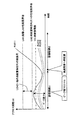
図7,図8は,正常なストレージ階層制御を説明する図である。図7は,ストレージ装置内の記憶装置群内のRAIDグループの負荷状態LOAD,再配置単位のアクセス頻度ARを示している。また,図8は,時間軸に対するアクセス頻度ARと負荷LOADの状態(性能限界値LM)を示している。ここでは,下位階層L2内のRAIDグループRAID21内の再配置単位RU211が注目されているものとする。
[Example of normal storage hierarchy control]
7 and 8 are diagrams for explaining normal storage tier control. FIG. 7 shows the load status LOAD of the RAID group in the storage device group in the storage device and the access frequency AR of the rearrangement unit. FIG. 8 shows the access frequency AR with respect to the time axis and the state of the load LOAD (performance limit value LM). Here, it is assumed that the rearrangement unit RU211 in the RAID group RAID21 in the lower hierarchy L2 is focused.
図8には,下位階層L2の性能限界値LM1と,再配置単位RU211の性能限界値LM2とが示され,LM1-ML2が再配置端子RU211以外の総負荷LOAD1になる。そして,評価期間t1において,再配置単位RU211のアクセス頻度ARのピーク値が10であることが示されている。図7には,評価期間t1で計測した各再配置単位のアクセス頻度ARが記入されている。これによれば,RAIDグループRAID21内の再配置単位RU211〜RU215のアクセス頻度ARは,10,5,7,0,3であり,それ以外の再配置単位RU216-21nの合計アクセス頻度ARは25である。したがって,RAIDグループRAID21の負荷率は,性能限界のアクセス回数が100とすると,50/100=50%となる。この負荷率は過負荷状態ではなく通常負荷状態である。 FIG. 8 shows the performance limit value LM1 of the lower hierarchy L2 and the performance limit value LM2 of the relocation unit RU211. LM1-ML2 is the total load LOAD1 other than the relocation terminal RU211. In the evaluation period t1, the peak value of the access frequency AR of the rearrangement unit RU211 is 10. In FIG. 7, the access frequency AR of each rearrangement unit measured in the evaluation period t1 is entered. According to this, the access frequency AR of the rearrangement units RU211 to RU215 in the RAID group RAID21 is 10, 5, 7, 0, 3, and the total access frequency AR of the other rearrangement units RU216-21n is 25. It is. Therefore, the load factor of the RAID group RAID21 is 50/100 = 50% when the number of accesses at the performance limit is 100. This load factor is not an overload state but a normal load state.
そして,再配置単位RU211のアクセス頻度ARが10であり,図8に示されるとおり,再配置閾値Vth(=8)を超えている。したがって,ストレージ階層制御により,次の評価期間t2において,再配置単位RU211のデータは上位階層L1に再配置される。その結果,図8に示されるとおり,評価期間t2において再配置単位RU211内のデータに対するアクセス頻度ARは大きく増大している。 The access frequency AR of the rearrangement unit RU211 is 10, which exceeds the rearrangement threshold Vth (= 8) as shown in FIG. Therefore, the data of the rearrangement unit RU211 is rearranged in the upper hierarchy L1 in the next evaluation period t2 by the storage hierarchy control. As a result, as shown in FIG. 8, the access frequency AR for the data in the relocation unit RU211 greatly increases during the evaluation period t2.
このように,正常なストレージ階層制御によれば,各RAIDグループは過負荷状態になく,評価期間t1で計測されたアクセス頻度ARが閾値Vthを超えていれば,次の評価期間t2ではより上位の階層に再配置され,より高速アクセスが可能になり,要求されるアクセス要求の増加に応えることができる。 Thus, according to normal storage tier control, each RAID group is not overloaded, and if the access frequency AR measured in the evaluation period t1 exceeds the threshold value Vth, it is higher in the next evaluation period t2. It can be rearranged in the above hierarchy, enabling faster access and responding to the increase in required access requests.
[正常でないストレージ階層制御の例]
図9,図10は,正常でないストレージ階層制御を説明する図である。図9,図10は,前述の図7,図8に対応する図である。
[Example of abnormal storage tier control]
9 and 10 are diagrams for explaining storage tier control that is not normal. 9 and 10 correspond to FIGS. 7 and 8 described above.
図9では,下位の階層L2内のRAIDグループRAID21が過負荷状態になり,各再配置単位RUのアクセス頻度ARが低下していることが示されている。各アクセス頻度ARには,過負荷状態の値と,括弧内の正常負荷状態の値(図7と同じ値)が示されている。すなわち,RAIDグループRAID21内の再配置単位RU211〜RU215のアクセス頻度ARは,5,3,5,0,1と低下し,それ以外の再配置単位RU216-21nの合計アクセス頻度ARは86と急増している。逆に言えば,再配置単位RU216-21nの合計アクセス頻度ARは86と急増したために,再配置単位RU211〜RU215のアクセス頻度ARが低下したともいえる。したがって,RAIDグループRAID21の負荷率は,性能限界のアクセス回数が100とすると,100/100=100%となり,この負荷率は過負荷状態である。 FIG. 9 shows that the RAID group RAID21 in the lower hierarchy L2 is overloaded, and the access frequency AR of each relocation unit RU is decreased. Each access frequency AR includes an overload value and a normal load value in parentheses (the same value as in FIG. 7). That is, the access frequency AR of the relocation units RU211 to RU215 in the RAID group RAID21 decreases to 5, 3, 5, 0, 1, and the total access frequency AR of the other relocation units RU216-21n rapidly increases to 86. doing. Conversely, since the total access frequency AR of the relocation unit RU216-21n has increased rapidly to 86, it can be said that the access frequency AR of the relocation units RU211 to RU215 has decreased. Therefore, the load factor of the RAID group RAID21 is 100/100 = 100%, assuming that the number of accesses at the performance limit is 100. This load factor is overloaded.
特に,再配置単位RU211は,本来要求されているアクセス頻度ARが10であったのに,属するRAIDグループRAID21が過負荷状態になりレスポンス遅延が生じて,実際に実行されたアクセス頻度ARは5に止まっている。このアクセス頻度は,本来サーバなどにより要求されているアクセス頻度とは異なっている。 In particular, although the relocation unit RU211 originally has an access frequency AR of 10 as requested, the RAID group RAID21 to which the relocation unit RU211 belongs is overloaded and a response delay occurs, and the access frequency AR actually executed is 5 It has stopped at. This access frequency is different from the access frequency originally requested by the server or the like.
図10に示されるとおり,評価期間t1において,再配置単位RU211以外の他の再配置単位RUの総負荷LOAD1が増大したため,再配置単位RU211の性能限界値LM2が低下し,再配置単位RU211のアクセス頻度ARはその性能限界値LM2を超えることができない。その結果,計測されたアクセス頻度ARは,ピーク値で5となり,要求されるアクセス頻度よりも少なくなっている。 As shown in FIG. 10, since the total load LOAD1 of the relocation unit RU other than the relocation unit RU211 has increased during the evaluation period t1, the performance limit value LM2 of the relocation unit RU211 decreases, and the relocation unit RU211 The access frequency AR cannot exceed the performance limit value LM2. As a result, the measured access frequency AR is 5 at the peak value, which is less than the required access frequency.
このアクセス頻度AR=5は,再配置閾値Vth=8より少ない。そのため,次の評価期間t2において,再配置単位RU211のデータは上位階層に再配置されず,下位の階層L2内に留まり続ける。これでは,適切なストレージ階層制御を行うことができない。 This access frequency AR = 5 is less than the rearrangement threshold Vth = 8. For this reason, in the next evaluation period t2, the data of the rearrangement unit RU211 is not rearranged in the upper hierarchy and remains in the lower hierarchy L2. This makes it impossible to perform appropriate storage tier control.
[本実施の形態によるストレージ階層制御の例]
図11は,本実施の形態によるストレージ階層制御が適用された場合のアクセス頻度と負荷状態の一例を示す図である。前述の図8,図10に対応する図である。また,図12は,評価期間t2における記憶装置群内のRAIDグループの負荷状態LOADと,再配置単位のアクセス頻度ARの一例を示す図である。図13は,評価期間t3における記憶装置群内のRAIDグループの負荷状態LOADと,再配置単位のアクセス頻度ARの一例を示す図である。
[Example of storage tier control according to this embodiment]
FIG. 11 is a diagram showing an example of the access frequency and the load state when the storage tier control according to this embodiment is applied. It is a figure corresponding to above-mentioned FIG. 8, FIG. FIG. 12 is a diagram illustrating an example of the load state LOAD of the RAID group in the storage device group and the access frequency AR of the relocation unit in the evaluation period t2. FIG. 13 is a diagram illustrating an example of the load state LOAD of the RAID group in the storage device group and the access frequency AR of the rearrangement unit in the evaluation period t3.
図12に示した評価期間t1,t2,t3の順に,本実施の形態によるストレージ階層制御が適用された場合の動作について具体的に説明する。 The operation when the storage tier control according to this embodiment is applied in the order of the evaluation periods t1, t2, and t3 shown in FIG. 12 will be specifically described.
[評価期間t1]
評価期間t1は,正常でないストレージ階層制御で説明した評価期間t2と同じである。すなわち,RAID21にアクセス要求が急増して性能限界を超えて過負荷状態になり,各再配置単位RUのアクセス頻度が低下し,要求されているアクセス頻度よりも低くなっている。
[Evaluation period t1]
The evaluation period t1 is the same as the evaluation period t2 described in the abnormal storage tier control. In other words, the number of access requests for
本実施の形態のストレージ階層制御は,図2のフローチャートに沿って実行される。評価期間t1の後半で,ストレージ階層制御装置20内の監視部21は,監視処理S1を実行する。すなわち,ストレージ装置10内のコントローラ12から,評価期間t1での各再配置単位RUのアクセス頻度ARと,各RAIDグループの負荷率(物理ディスクの使用率)LOADの計測結果を取得して監視する。
The storage tier control of this embodiment is executed according to the flowchart of FIG. In the second half of the evaluation period t1, the
取得したアクセス頻度と負荷率は,図9に示されるのと同じである。すなわち,下位の階層L2内の再配置単位RU211は過負荷状態によりそのアクセス頻度ARが5と低く抑えられて計測され,この再配置単位RU211を有するRAIDグループRAID21が過負荷状態であることが計測される。 The acquired access frequency and load factor are the same as those shown in FIG. That is, the relocation unit RU211 in the lower hierarchy L2 is measured with its access frequency AR being kept low at 5 due to an overload condition, and it is measured that the RAID group RAID21 having this relocation unit RU211 is in an overload condition Is done.
次に,ストレージ階層制御装置20内の評価部22は,評価処理S2を実行し,計測された再配置単位のアクセス頻度ARを評価して,再配置の候補リストを作成する。すなわち,下位の階層L2内の第1の閾値を超えるアクセス頻度が計測された再配置単位RUを,より上位の階層に再配置する候補に指定し,上位の階層L1内の第2の閾値を下回るアクセス頻度が計測された再配置単位RUを,より下位の階層に再配置する候補に指定して,候補リストを作成する。しかし,RAIDグループRAID21内の全ての再配置単位のアクセス頻度が抑制されて計測されているため,再配置単位RU211は再配置候補リストには入らず再配置対象にはならない。
Next, the
そして,ストレージ階層制御装置20内の再配置部23は,再配置処理S3を実行する。再配置部23は,評価部22で作成した再配置候補リストにしたがって,候補の再配置単位内のデータについて再配置を実行する。ただし,評価期間t1での計測結果によっては再配置候補リストには再配置単位RU211などは入っていない。よって,再配置部23は評価期間t1では再配置処理を行わない。
Then, the
次に,ストレージ階層制御装置20内の過負荷制御部24は,過負荷制御処理S4を実行する。すなわち,過負荷制御部24は,過負荷状態のRAIDグループRAID21内に存在する再配置単位RU211-21nのうち,相対的にアクセス頻度ARが高いものをキャッシュ候補としてSSDキャッシュ制御部121に通知する。また,既に,評価期間t1においてキャッシュメモリユニット13内に強制的に保持されていたデータがあれば,強制保持の終了をSSDキャッシュ制御部121に通知する。
Next, the
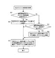
図14は,過負荷制御処理S4のフローチャート図である。過負荷制御部24は,SSDキャッシュ制御部121にSSDキャッシュ132内での強制的な保持の終了を指示する(S11)。この処理の意味については後述する。そして,過負荷制御部24は,評価期間t1において過負荷状態になっていたRAIDグループのテーブル(図16)を作成する(S12)。
FIG. 14 is a flowchart of the overload control process S4. The
図16は,過負荷状態のRAIDグループのテーブルの一例を示す図である。図9に示した評価期間t1では,RAIDグループRAID21が過負荷状態と評価されているので,図16の過負荷状態RAIDグループテーブルには,RAIDグループRAID21の「21」が記載されている。 FIG. 16 is a diagram illustrating an example of an overloaded RAID group table. In the evaluation period t1 shown in FIG. 9, since the RAID group RAID21 is evaluated to be overloaded, “21” of the RAID group RAID21 is described in the overloaded RAID group table of FIG.
次に,過負荷制御部24は,過負荷状態のRAIDグループ毎に,アクセス頻度順に再配置単位を並べたキャッシュ保持候補テーブル(図17)を作成する(S13)。このキャッシュ保持候補テーブルには,少なくとも各RAIDグループの過負荷状態を解消できるだけの再配置単位がリストアップされる。
Next, the
図17は,キャッシュ保持候補テーブルの一例を示す図である。図17には,RAIDグループRAID21の再配置単位RU211,RU213の番号211,213,212,215がリストアップされている。つまり,RAIDグループRAID21は過負荷状態で各再配置単位のアクセス頻度は抑制されてはいるが,その中でもアクセス頻度が高い順に再配置単位がキャッシュ保持候補としてリストアップされる。
FIG. 17 is a diagram illustrating an example of the cache retention candidate table. In FIG. 17, the
図9に示されるとおり,RAIDグループRAID21内のアクセス頻度ARが高い再配置単位RU211,RU213のアクセス頻度AR,5,5,を性能限界100から減算すると90となり,過負荷状態の閾値,例えば92を下回ることになる。したがって,少なくとも再配置単位RU211,213をキャッシュ保持候補としてキャッシュ保持候補テーブルにリストアップしておけば,後述するSSDキャッシュ制御でキャッシュ保持される。
As shown in FIG. 9, subtracting the access frequencies AR, 5, 5, and 5 of the relocation units RU211, RU213 having a high access frequency AR in the RAID group RAID21 from the
次に,過負荷制御部24は,キャッシュ保持候補テーブルにしたがい,キャッシュ保持候補の再配置単位をSSDキャッシュ制御部121に指示する(S14)。この場合,過負荷制御部24は,SSDキャッシュ121内のSSDキャッシュ保持領域を満たすまで,キャッシュ保持候補テーブル内の再配置単位をキャッシュ保持候補として指示する。
Next, the
ここで,SSDキャッシュ121内のSSDキャッシュ保持領域として確保すべき容量について説明する。このSSDキャッシュ保持領域の容量は,少なくとも1つの再配置単位の容量を有することが望ましい。SSDキャッシュ保持領域の容量が,1つの再配置単位の容量と同じ場合は,少なくとも最もアクセス頻度が高かった再配置単位がキャッシュ保持候補としてSSDキャッシュ制御部121に指示される。その結果,後述するSSDキャッシュ制御部による制御で,指定された1つの再配置単位内のデータがアクセスの度にSSDキャッシュ132内に保持される。このように保持されれば,少なくとも1つの再配置単位のデータに対するアクセスを適正に発生させることができ,適正なアクセス頻度の計測を行うことができる。そして,評価期間毎にキャッシュ保持される再配置単位を変更していけば,時間がかかるかもしれないが,やがて要求されるアクセス頻度が高いデータをより上位の階層に再配置することができる。
Here, the capacity to be secured as the SSD cache holding area in the
図15は,SSDキャッシュ制御部の処理を示すフローチャート図である。最初に,SSDキャッシュ制御部121は,ストレージ階層制御装置20内の過負荷制御部24からキャッシュ保持候補の再配置単位の指示を受信する(S21)。ここでの例では,少なくとも再配置単位RU211,RU213がキャッシュ保持候補として指示されるものとする。
FIG. 15 is a flowchart showing processing of the SSD cache control unit. First, the SSD
これに応答して,SSDキャッシュ制御部121は,SSDキャッシュ保持対象テーブル(図18)に,そのキャッシュ保持候補を追加する(S22)。また,SSDキャッシュ制御部121は,過負荷制御部24からキャッシュ保持終了の指示を受信する(S23)。受信した場合は,SSDキャッシュ制御部121は,SSDキャッシュ保持対象テーブルからそのキャッシュ保持終了対象の再配置単位を削除する(S24)。
In response to this, the SSD
図18は,SSDキャッシュ保持対象テーブルの一例を示す図である。ここの例では,SSDキャッシュ保持対象テーブル内には,RAIDグループRAID21内の再配置単位RU211,RU213がリストアップされている。 FIG. 18 is a diagram illustrating an example of the SSD cache holding target table. In this example, the relocation units RU211, RU213 in the RAID group RAID21 are listed in the SSD cache retention target table.
[評価期間t2]
このようにして作成されたSSDキャッシュ保持対象テーブルに基づいて,SSDキャッシュ制御部121は,キャッシュメモリユニット13内のキャッシュメモリ131からあふれて書き込まれたデータのうち,SSDキャッシュ保持対象テーブルで指定されている再配置単位RU211,RU213内のデータについては,SSDキャッシュ保持領域内に強制的に保持する。そして,次の評価期間t2の間は,他のデータの書き込みによりSSDキャッシュ132からあふれることがないように制御する(S25)。
[Evaluation period t2]
Based on the SSD cache retention target table created in this way, the SSD
具体的には,SSDキャッシュ制御部121は,SSDキャッシュ保持対象テーブルにリストアップされている再配置単位RU211,RU213内へのアクセスが発生した場合に,キャッシュメモリ131に書き込み,評価期間t2の間は,少なくともSSDキャッシュ132からあふれて削除されないように制御する。つまり,通常のキャッシュ制御により,アクセスされたデータはキャッシュメモリ131に格納され,そこからあふれたときにSSDキャッシュ132に格納される。しかし,上記の制御により,SSDキャッシュ132からはあふれて削除されない。再配置単位RU211,RU213内へのアクセスが発生しない場合は,そもそもキャッシュ制御の対象にはならない。
Specifically, the SSD
図12に評価期間t2の状態が示されている。すなわち,評価期間t1で作成されたSSDキャッシュ保持対象テーブル(図18)に基づいて,SSDキャッシュ制御部121が,再配置単位RU211,RU213へのアクセスがあった場合に,そのアクセス領域を含む所定領域のデータをSSDキャッシュ132内に強制的に保持する。この所定領域のデータは,キャッシュ制御単位の領域のデータである。
FIG. 12 shows the state during the evaluation period t2. That is, when the SSD
上記のキャッシュ制御は,具体的には,図12に示されるとおり,再配置単位RU211,RU213にアクセスが発生すると,そのデータが一旦はキャッシュメモリ131に格納され,その後通常のキャッシュ制御によりSSDキャッシュ132に格納され保持される。なお,キャッシュの単位は,必ずしも再配置単位ではなく,それより少ないアクセスデータを含むキャッシュ制御単位の領域のデータである。
Specifically, in the above cache control, as shown in FIG. 12, when the relocation units RU211, RU213 are accessed, the data is temporarily stored in the
そして,評価期間t2でも,評価期間t1と同様に,ストレージ階層制御装置20が,図2の監視処理S1と評価処理S2と再配置処理S3と過負荷制御処理S4を実行する。評価期間t2では,再配置単位RU211,213へのアクセス要求は最初の要求を除いてキャッシュメモリユニットで全てキャッシュヒットし応答処理される。したがって,それらのアクセス頻度ARは要求されるアクセス頻度に対応した頻度になる。図12によれば,評価期間t2において,RAIDグループRAID21内の再配置単位RU211,RU213に対するアクセス頻度は最初の1回だけに止まり,その後のアクセス要求はSSDキャッシュ132で処理されて,そこでのアクセス頻度ARはそれぞれ9,6となっている。
In the evaluation period t2, as in the evaluation period t1, the storage
したがって,評価期間t2での再配置単位RU211,213へのアクセス頻度は,それぞれ1+9=10,1+6=7と適切に計測される。すなわち,図11に示されるとおり,評価期間t2において,SSDキャッシュ保持されている再配置単位RU211へのアクセス頻度は10となり,再配置の閾値Vthを超えることになる。 Therefore, the access frequencies to the rearrangement units RU211, 213 in the evaluation period t2 are appropriately measured as 1 + 9 = 10 and 1 + 6 = 7, respectively. That is, as shown in FIG. 11, in the evaluation period t2, the access frequency to the relocation unit RU211 held in the SSD cache is 10, which exceeds the relocation threshold value Vth.
ストレージ階層制御装置20内の監視部21が,評価期間t2での再配置単位毎のアクセス頻度と,RAIDグループ毎の負荷状態の計測結果をコントローラ12から取得して監視する。この計測結果によれば,RAIDグループRAID21はもはや過負荷状態ではないことが判明し,再配置単位RU211のアクセス頻度が再配置の閾値を超えていることが判明する。
The
そして,評価部22が,上記の計測データを評価して,再配置単位RU211を再配置候補にリストアップする。その結果,ストレージ階層制御装置20内の再配置部23が,再配置単位RU211のデータを上位の階層L1内のRAIDグループRAID11内のいずれかの再配置単位内に格納する。この再配置処理により,次の評価期間t3では,再配置単位RU211のデータは上位の階層L1でアクセス処理されるので,サーバが要求する高いアクセス頻度を満たすことができる。
Then, the
さらに,過負荷制御部24は,図14に示した処理を実行する。これにより,評価期間t2でSSDキャッシュ保持されていた再配置単位RU211,RU213の保持状態が解除され(S11),過負荷状態のRAIDグループのテーブル(図16)からRAIDグループRAID21が削除され(S12),SSDキャッシュ保持候補テーブルにもリストアップされない(S13)。したがって,SSDキャッシュ制御部へのSSDキャッシュ保持候補の指示は行われない(S14)。
Further, the
[評価期間t3]
図13に示されるとおり,評価期間t3では,SSDキャッシュ制御部121が,過負荷制御部24からの終了指示に応答して,再配置単位RU211のSSDキャッシュ保持制御を終了し,通常のキャッシュ制御によって,アクセス頻度が下がればSSDキャッシュ132からあふれて削除される。またSSDキャッシュ制御部121は,過負荷制御処理部24から新たなSSDキャッシュ保持候補が指示されないので,評価期間t3ではSSDキャッシュ保持する対象はない。
[Evaluation period t3]
As shown in FIG. 13, in the evaluation period t3, the SSD
そして,下位の階層L2内の再配置単位RU211のデータは,上位の階層L1に再配置されているので,上位の階層L1の高いアクセス速度でアクセス処理されるので,サーバから要求されるアクセス頻度を満たすことができる。そのため,図11に示されるとおり,評価期間t3において,再配置単位RU211内に格納されていたデータのアクセス頻度は急増している。 Since the data of the rearrangement unit RU211 in the lower hierarchy L2 has been rearranged in the upper hierarchy L1, access processing is performed at a higher access speed of the upper hierarchy L1, so the access frequency required from the server Can be met. Therefore, as shown in FIG. 11, the access frequency of the data stored in the rearrangement unit RU211 increases rapidly in the evaluation period t3.
以上の通り,本実施の形態によれば,過負荷状態になっている物理ディスク内の再配置単位のデータを,評価期間の間,通常のSSDキャッシュ制御にかかわらずSSDキャッシュ132内に保持されるようにして,サーバから要求されるアクセス頻度を適正に計測できるようにする。それにより,過負荷状態の物理ディスク内に要求されるアクセス頻度が高い再配置単位のデータが下位の階層L2内に留まり続けることが回避され,アクセス頻度を適正に計測でき,適切にストレージ階層制御を行うことができる。
As described above, according to this embodiment, relocation unit data in an overloaded physical disk is held in the
したがって,閑散期と繁忙期を繰り返すような業務や,長期間停止していた業務が急に再開されるような季節性業務に対して,ストレージ自動階層制御を適用する際に,慣らし運転や手動による再配置などの煩雑な運用を回避することができる。 Therefore, when applying automated storage tier control to operations that repeat periods of low and busy periods, or seasonal operations that have been suspended for a long period of time, the break-in operation or manual operation It is possible to avoid complicated operations such as rearrangement due to.
上記の実施の形態において,キャッシュメモリユニット13は,DRAMのキャッシュメモリ131だけで構成されてもよい。その場合は,SSDキャッシュ制御部の代わって,コントローラ12のキャッシュ制御において,候補に指定された再配置領域RU211のアクセスデータをキャッシュメモリ131内の強制的に保持することで,同様にアクセス頻度を適切に計測し,適切なストレージ階層制御を行う。
In the above embodiment, the
上記の実施の形態において,物理ディスクは,RAID構成でなく,1個のHDDで構成されていてもよい。いずれにしても,物理ディスクの使用率に基づいて,それが過負荷状態か否かが判定される。 In the above embodiment, the physical disk may be configured by one HDD instead of the RAID configuration. In any case, based on the usage rate of the physical disk, it is determined whether or not it is overloaded.
以上の実施の形態をまとめると,以下の付記のとおりである。 The above embodiment is summarized as follows.
(付記1)
第1のアクセス速度を有する第1の記憶装置と,前記第1のアクセス速度より遅い第2のアクセス速度を有する第2の記憶装置と,キャッシュメモリとを有するストレージの制御処理をコンピュータに実行させるストレージ制御プログラムであって,
前記制御処理は,
前記第1及び第2の記憶装置内のデータへのアクセス頻度を監視する監視処理と,
前記第2の記憶領域内の前記アクセス頻度が第1の基準値を超えるデータを前記第1の記憶装置に再配置する再配置処理と,
前記第2の記憶装置が過負荷状態の場合に,前記第2の記憶領域内の少なくとも一部のデータを前記キャッシュメモリに保持する過負荷処理とを有し,
前記一部のデータを前記キャッシュメモリに保持した状態で前記監視処理を実行し,前記一部のデータへのアクセス頻度に基づいて前記再配置処理を実行するストレージ制御プログラム。
(Appendix 1)
Causing a computer to execute control processing of a storage having a first storage device having a first access speed, a second storage device having a second access speed slower than the first access speed, and a cache memory A storage control program,
The control process is:
Monitoring processing for monitoring the access frequency to the data in the first and second storage devices;
A relocation process for relocating data in the second storage area whose access frequency exceeds a first reference value to the first storage device;
An overload process for holding at least a part of the data in the second storage area in the cache memory when the second storage device is in an overload state;
A storage control program that executes the monitoring process in a state where the partial data is held in the cache memory, and executes the relocation process based on an access frequency to the partial data.
(付記2)
付記1において,
さらに,前記第1または第2の記憶装置内のアクセス要求が行われた第1のデータを前記キャッシュメモリに書き込み,第2のデータの前記キャッシュメモリへの書き込みにより前記第1のデータを前記キャッシュメモリから削除するキャッシュ制御処理を有し,
前記監視処理と再配置処理は,評価期間毎に繰り返し実行され,
前記過負荷処理は,前記評価期間の間,前記キャッシュ制御処理にかかわらず前記一部のデータを前記キャッシュメモリに保持するストレージ制御プログラム。
(Appendix 2)
In
Further, the first data requested to be accessed in the first or second storage device is written into the cache memory, and the first data is written into the cache memory by writing the second data into the cache memory. It has a cache control process to delete from memory,
The monitoring process and the rearrangement process are repeatedly executed every evaluation period,
The overload process is a storage control program that holds the partial data in the cache memory during the evaluation period regardless of the cache control process.
(付記3)
付記1において,
前記再配置処理は,前記第1及び第2の記憶装置内の再配置単位内のデータを,前記再配置単位のデータへのアクセス頻度に応じて再配置し,
前記過負荷処理は,アクセス要求が発生した場合に,前記アクセス要求が発生した前記再配置単位内の前記一部のデータを前記キャッシュメモリに保持するストレージ制御プログラム。
(Appendix 3)
In
The rearrangement process rearranges the data in the rearrangement unit in the first and second storage devices according to the frequency of access to the data in the rearrangement unit,
The overload processing is a storage control program for holding the partial data in the relocation unit in which the access request is generated in the cache memory when the access request is generated.
(付記4)
付記3において,
前記監視処理は,前記再配置単位内のデータへのアクセス頻度を,前記キャッシュメモリに保持されている前記一部のデータへのアクセスと前記再配置単位内のデータへのアクセスの合計数に基づいて計測するストレージ制御プログラム。
(Appendix 4)
In
The monitoring processing is based on the access frequency to the data in the relocation unit based on the total number of accesses to the partial data and the data in the relocation unit held in the cache memory. Storage control program to measure.
(付記5)
付記3において,
前記過負荷処理は,前記過負荷状態にある第2の記憶装置内の少なくとも最もアクセス頻度が高い再配置単位に対して,前記アクセス要求が発生した前記一部のデータを前記キャッシュメモリに書込み保持するよう前記ストレージに指示するストレージ制御プログラム。
(Appendix 5)
In
In the overload processing, the partial data in which the access request is generated is written and held in the cache memory for at least the relocation unit having the highest access frequency in the second storage device in the overload state. A storage control program that instructs the storage to do.
(付記6)
付記5において,
前記過負荷処理は,前記過負荷状態にある第2の記憶装置を通常負荷状態にできるようなアクセス頻度が計測された1つのまたは複数の再配置単位に対して,前記キャッシュメモリへの保持を指示するストレージ制御プログラム。
(Appendix 6)
In
In the overload process, one or a plurality of relocation units whose access frequencies are measured so that the second storage device in the overload state can be set in a normal load state are held in the cache memory. The storage control program to indicate.
(付記7)
付記3において,
前記キャッシュメモリ内の前記一部のデータを前記キャッシュ制御処理にかかわらず保持する容量は,少なくとも1つの再配置単位のデータを保持できる容量であるストレージ制御プログラム。
(Appendix 7)
In
A storage control program in which the capacity for holding the partial data in the cache memory regardless of the cache control processing is a capacity capable of holding at least one relocation unit data.
(付記8)
付記1において,
前記第2の記憶装置は,複数のRAIDグループを有し,
前記監視処理は,前記複数のRAIDグループそれぞれの物理ディスクの使用率を監視し,
前記第2の記憶装置が過負荷状態になる場合は,前記使用率が第2の基準値を超える場合を含むストレージ制御プログラム。
(Appendix 8)
In
The second storage device has a plurality of RAID groups,
The monitoring process monitors the usage rate of each physical disk of the plurality of RAID groups,
A storage control program including a case where the usage rate exceeds a second reference value when the second storage device is overloaded.
(付記9)
付記1において,
前記第1及び第2の記憶装置は,複数の論理ボリュームに割り当てられ,
前記監視処理は,前記論理ボリュームへのアクセス処理に基づいて,前記再配置単位のアクセス頻度を計測するストレージ制御プログラム。
(Appendix 9)
In
The first and second storage devices are assigned to a plurality of logical volumes;
The monitoring process is a storage control program for measuring an access frequency of the relocation unit based on an access process to the logical volume.
(付記10)
第1のアクセス速度を有する第1の記憶装置と,前記第1のアクセス速度より遅い第2のアクセス速度を有する第2の記憶装置と,キャッシュメモリとを有するストレージの制御方法であって,
前記第1及び第2の記憶装置内のデータへのアクセス頻度を監視する監視処理工程と,
前記第2の記憶領域内の前記アクセス頻度が第1の基準値を超えるデータを前記第1の記憶装置に再配置する再配置処理工程と,
前記第2の記憶装置が過負荷状態の場合に,前記第2の記憶領域内の少なくとも一部のデータを前記キャッシュメモリに保持する過負荷処理工程とを有し,
前記一部のデータを前記キャッシュメモリに保持した状態で前記監視処理工程を実行し,前記一部のデータへのアクセス頻度に基づいて前記再配置処理工程を実行するストレージ制御方法。
(Appendix 10)
A storage control method comprising: a first storage device having a first access speed; a second storage device having a second access speed slower than the first access speed; and a cache memory,
A monitoring process for monitoring the frequency of access to the data in the first and second storage devices;
A relocation processing step of relocating data in the second storage area in which the access frequency exceeds a first reference value in the first storage device;
An overload processing step of holding at least a part of data in the second storage area in the cache memory when the second storage device is in an overload state;
A storage control method, wherein the monitoring process is executed with the partial data held in the cache memory, and the relocation process is executed based on an access frequency to the partial data.
(付記11)
第1のアクセス速度を有する第1の記憶装置と,前記第1のアクセス速度より遅い第2のアクセス速度を有する第2の記憶装置と,キャッシュメモリとを有するストレージと,
前記ストレージの階層制御を行うストレージ階層制御装置とを有し,
前記ストレージ階層制御装置は,
前記第1及び第2の記憶装置内のデータへのアクセス頻度を監視する監視処理部と,
前記第2の記憶領域内の前記アクセス頻度が第1の基準値を超えるデータを前記第1の記憶装置に再配置する再配置処理部と,
前記第2の記憶装置が過負荷状態の場合に,前記第2の記憶領域内の少なくとも一部のデータを前記キャッシュメモリに保持する過負荷処理部とを有し,
前記一部のデータを前記キャッシュメモリに保持した状態で前記監視処理部が前記監視を実行し,前記一部のデータへのアクセス頻度に基づいて前記再配置処理部が前記再配置を実行するストレージシステム。
(Appendix 11)
A storage device having a first storage device having a first access speed, a second storage device having a second access speed slower than the first access speed, and a cache memory;
A storage tier control device that performs tier control of the storage,
The storage tier control device
A monitoring processor for monitoring the frequency of access to the data in the first and second storage devices;
A relocation processing unit for relocating data in the second storage area in which the access frequency exceeds a first reference value in the first storage device;
An overload processing unit for holding at least a part of the data in the second storage area in the cache memory when the second storage device is in an overload state;
Storage in which the monitoring processing unit executes the monitoring while the partial data is held in the cache memory, and the relocation processing unit executes the relocation based on an access frequency to the partial data system.
(付記12)
付記11において,
前記キャッシュメモリは,第3のアクセス速度を有する第1のキャッシュメモリと,前記第3のアクセス速度より遅い第4のアクセス速度を有するSSDキャッシュとを有するストレージシステム。
(Appendix 12)
In Appendix 11,
The storage system includes a first cache memory having a third access speed and an SSD cache having a fourth access speed that is slower than the third access speed.
(付記13)
第1のアクセス速度を有する第1の記憶装置と,前記第1のアクセス速度より遅い第2のアクセス速度を有する第2の記憶装置と,キャッシュメモリとを有するストレージの階層制御を行うストレージ階層制御装置であって,
前記第1及び第2の記憶装置内のデータへのアクセス頻度を監視する監視処理部と,
前記第2の記憶領域内の前記アクセス頻度が第1の基準値を超えるデータを前記第1の記憶装置に再配置する再配置処理部と,
前記第2の記憶装置が過負荷状態の場合に,前記第2の記憶領域内の少なくとも一部のデータを前記キャッシュメモリに保持する過負荷処理部とを有し,
前記一部のデータを前記キャッシュメモリに保持した状態で前記監視処理部が前記監視を実行し,前記一部のデータへのアクセス頻度に基づいて前記再配置処理部が前記再配置を実行するストレージ階層制御装置。
(Appendix 13)
Storage tier control for performing tier control of a storage having a first storage device having a first access speed, a second storage device having a second access speed slower than the first access speed, and a cache memory A device,
A monitoring processor for monitoring the frequency of access to the data in the first and second storage devices;
A relocation processing unit for relocating data in the second storage area in which the access frequency exceeds a first reference value in the first storage device;
An overload processing unit for holding at least a part of the data in the second storage area in the cache memory when the second storage device is in an overload state;
Storage in which the monitoring processing unit executes the monitoring while the partial data is held in the cache memory, and the relocation processing unit executes the relocation based on an access frequency to the partial data Hierarchical control device.
10:ストレージ装置
12:コントローラ
13:キャッシュメモリユニット(キャッシュメモリ)
14:記憶装置群
RAID:RAIDグループ
RU:再配置単位
20:ストレージ階層制御装置
10: Storage device 12: Controller 13: Cache memory unit (cache memory)
14: Storage device group
RAID: RAID group
RU: Relocation unit 20: Storage hierarchy control device
Claims (11)
前記制御処理は,
前記第1及び第2の記憶装置内の再配置単位のデータへのアクセス頻度を監視する監視処理と,
前記第2の記憶装置内の前記アクセス頻度が第1の基準値を超える前記再配置単位のデータを前記第1の記憶装置に再配置する再配置処理と,
前記第2の記憶装置が過負荷状態の場合に,前記第2の記憶装置内の少なくとも一部のデータが前記キャッシュ制御処理により前記キャッシュメモリに記憶されたら前記監視処理中は前記一部のデータを前記キャッシュメモリに保持し,前記一部のデータへのアクセス要求時に前記キャッシュ制御処理により前記キャッシュメモリ内の前記一部のデータがアクセスされる過負荷処理とを有し,
前記一部のデータを前記キャッシュメモリに保持した状態で前記監視処理を実行し,前記再配置単位のデータへのアクセス頻度に基づいて前記再配置処理を実行するストレージ制御プログラム。 First storage device having a first access speed, said second storage device having a slower second access speed than the first access speed, have a cache memory, the first or second When an access request to data in the storage device is made, if the data at the address of the access request is stored in the cache memory, the data in the cache memory is accessed, and if not stored, the first or second storage Storage control for accessing the access request data in the apparatus and storing the access data in the cache memory and causing the computer to execute a storage control process in which a cache control process is performed to delete the data stored in the past from the cache memory A program,
The control process is:
Monitoring processing for monitoring the frequency of access to relocation unit data in the first and second storage devices;
Relocation processing for relocating data of the relocation unit in which the access frequency in the second storage device exceeds a first reference value to the first storage device;
When at least a part of data in the second storage device is stored in the cache memory by the cache control process when the second storage device is in an overload state, the part of the data during the monitoring process In the cache memory, and an overload process in which the part of the data in the cache memory is accessed by the cache control process when an access request to the part of the data is made ,
A storage control program that executes the monitoring process with the partial data held in the cache memory, and executes the relocation process based on an access frequency to the data of the relocation unit .
前記監視処理と再配置処理は,評価期間毎に繰り返し実行され,
前記過負荷処理は,前記評価期間の間,前記キャッシュ制御処理にかかわらず前記一部のデータを前記キャッシュメモリに保持するストレージ制御プログラム。 In claim 1,
The monitoring process and the rearrangement process are repeatedly executed every evaluation period,
The overload process is a storage control program that holds the partial data in the cache memory during the evaluation period regardless of the cache control process.
前記過負荷処理は,アクセス要求が発生した場合に,前記アクセス要求が発生した前記再配置単位内の前記一部のデータを前記キャッシュメモリに保持するストレージ制御プログラム。 In claim 1,
The overload processing is a storage control program for holding the partial data in the relocation unit in which the access request is generated in the cache memory when the access request is generated.
前記監視処理は,前記再配置単位内のデータへのアクセス頻度を,前記キャッシュメモリに保持されている前記一部のデータへのアクセスと前記再配置単位内のデータへのアクセスの合計数に基づいて計測するストレージ制御プログラム。 In claim 3,
The monitoring processing is based on the access frequency to the data in the relocation unit based on the total number of accesses to the partial data and the data in the relocation unit held in the cache memory. Storage control program to measure.
前記過負荷処理は,前記過負荷状態にある第2の記憶装置内の少なくとも最もアクセス頻度が高い再配置単位に対して,前記アクセス要求が発生した前記一部のデータを前記キャッシュメモリに書込み保持するよう前記ストレージに指示するストレージ制御プログラム。 In claim 3,
In the overload processing, the partial data in which the access request is generated is written and held in the cache memory for at least the relocation unit having the highest access frequency in the second storage device in the overload state. A storage control program that instructs the storage to do.
前記過負荷処理は,前記過負荷状態にある第2の記憶装置を通常負荷状態にできるようなアクセス頻度が計測された1つのまたは複数の再配置単位に対して,前記キャッシュメモリへの保持を指示するストレージ制御プログラム。 In claim 5,
In the overload process, one or a plurality of relocation units whose access frequencies are measured so that the second storage device in the overload state can be set in a normal load state are held in the cache memory. The storage control program to indicate.
前記キャッシュメモリ内の前記一部のデータを前記キャッシュ制御処理にかかわらず保持する容量は,少なくとも1つの再配置単位のデータを保持できる容量であるストレージ制御プログラム。 In claim 3,
A storage control program in which the capacity for holding the partial data in the cache memory regardless of the cache control processing is a capacity capable of holding at least one relocation unit data.
前記第2の記憶装置は,複数のRAIDグループを有し,
前記監視処理は,前記複数のRAIDグループそれぞれの物理ディスクの使用率を監視し,
前記第2の記憶装置が過負荷状態になる場合は,前記使用率が第2の基準値を超える場合を含むストレージ制御プログラム。 In claim 1,
The second storage device has a plurality of RAID groups,
The monitoring process monitors the usage rate of each physical disk of the plurality of RAID groups,
A storage control program including a case where the usage rate exceeds a second reference value when the second storage device is overloaded.
前記第1及び第2の記憶装置内の再配置単位のデータへのアクセス頻度を監視する監視処理工程と,
前記第2の記憶装置内の前記アクセス頻度が第1の基準値を超える前記再配置単位のデータを前記第1の記憶装置に再配置する再配置処理工程と,
前記第2の記憶装置が過負荷状態の場合に,前記第2の記憶装置内の少なくとも一部のデータが前記キャッシュ制御処理により前記キャッシュメモリに記憶されたら前記監視処理工程中は前記一部のデータを前記キャッシュメモリに保持し,前記一部のデータへのアクセス要求時に前記キャッシュ制御処理により前記キャッシュメモリ内の前記一部のデータがアクセスされる過負荷処理工程とを有し,
前記一部のデータを前記キャッシュメモリに保持した状態で前記監視処理工程を実行し,前記再配置単位のデータへのアクセス頻度に基づいて前記再配置処理工程を実行するストレージ制御方法。 First storage device having a first access speed, said second storage device having a slower second access speed than the first access speed, have a cache memory, the first or second When an access request to data in the storage device is made, if the data at the address of the access request is stored in the cache memory, the data in the cache memory is accessed, and if not stored, the first or second storage A storage control method for performing cache control processing for accessing the access request data in the apparatus and storing the access data in the cache memory and deleting the data stored in the past from the cache memory ,
A monitoring process for monitoring the frequency of access to relocation unit data in the first and second storage devices;
A rearrangement processing step of rearranging the data of the rearrangement unit in which the access frequency in the second storage device exceeds a first reference value in the first storage device;
When the second storage device is in an overload state, if at least a part of the data in the second storage device is stored in the cache memory by the cache control process, the part of the data is not displayed during the monitoring process. An overload processing step of holding data in the cache memory and accessing the partial data in the cache memory by the cache control process when an access request to the partial data is made ,
A storage control method that executes the monitoring process step with the partial data held in the cache memory, and executes the relocation process step based on an access frequency to the data of the relocation unit .
前記ストレージの階層制御を行うストレージ階層制御装置とを有し,
前記ストレージ階層制御装置は,
前記第1及び第2の記憶装置内の再配置単位のデータへのアクセス頻度を監視する監視処理部と,
前記第2の記憶装置内の前記アクセス頻度が第1の基準値を超える前記再配置単位のデータを前記第1の記憶装置に再配置する再配置処理部と,
前記第2の記憶装置が過負荷状態の場合に,前記第2の記憶装置内の少なくとも一部のデータが前記キャッシュ制御処理により前記キャッシュメモリに記憶されたら前記監視中は前記一部のデータを前記キャッシュメモリに保持し,前記一部のデータへのアクセス要求時に前記キャッシュ制御処理により前記キャッシュメモリ内の前記一部のデータがアクセスされる過負荷処理部とを有し,
前記一部のデータを前記キャッシュメモリに保持した状態で前記監視処理部が前記監視を実行し,前記再配置単位のデータへのアクセス頻度に基づいて前記再配置処理部が前記再配置を実行するストレージシステム。 First storage device having a first access speed, said second storage device having a slower second access speed than the first access speed, have a cache memory, the first or second When an access request to data in the storage device is made, if the data at the address of the access request is stored in the cache memory, the data in the cache memory is accessed, and if not stored, the first or second storage A storage in which cache control processing is performed to access the access request data in the apparatus and store the access data in the cache memory and to delete data stored in the past from the cache memory ;
A storage tier control device that performs tier control of the storage,
The storage tier control device
A monitoring processing unit for monitoring the access frequency to the data of the rearrangement unit in the first and second storage devices;
A rearrangement processing unit for rearranging the data of the rearrangement unit in which the access frequency in the second storage device exceeds a first reference value in the first storage device;
When the second storage device is in an overload state, if at least a part of data in the second storage device is stored in the cache memory by the cache control process, the part of the data is stored during the monitoring. An overload processing unit that is held in the cache memory and is accessed by the cache control process when the access to the partial data is requested ,
The monitoring processing unit executes the monitoring with the partial data held in the cache memory, and the relocation processing unit executes the relocation based on the frequency of access to the data of the relocation unit. Storage system.
前記第1及び第2の記憶装置内の再配置単位のデータへのアクセス頻度を監視する監視処理部と,
前記第2の記憶装置内の前記アクセス頻度が第1の基準値を超える前記再配置単位のデータを前記第1の記憶装置に再配置する再配置処理部と,
前記第2の記憶装置が過負荷状態の場合に,前記第2の記憶装置内の少なくとも一部のデータが前記キャッシュ制御処理により前記キャッシュメモリに記憶されたら前記監視中は前記一部のデータを前記キャッシュメモリに保持し,前記一部のデータへのアクセス要求時に前記キャッシュ制御処理により前記キャッシュメモリ内の前記一部のデータがアクセスされる過負荷処理部とを有し,
前記一部のデータを前記キャッシュメモリに保持した状態で前記監視処理部が前記監視を実行し,前記再配置単位のデータへのアクセス頻度に基づいて前記再配置処理部が前記再配置を実行するストレージ階層制御装置。 First storage device having a first access speed, said second storage device having a slower second access speed than the first access speed, have a cache memory, the first or second When an access request to data in the storage device is made, if the data at the address of the access request is stored in the cache memory, the data in the cache memory is accessed, and if not stored, the first or second storage A storage tier control apparatus that performs tier control of storage in which cache control processing is performed to access the access request data in the apparatus, store the access data in the cache memory, and delete data stored in the past from the cache memory. There,
A monitoring processing unit for monitoring the access frequency to the data of the rearrangement unit in the first and second storage devices;
A rearrangement processing unit for rearranging the data of the rearrangement unit in which the access frequency in the second storage device exceeds a first reference value in the first storage device;
When the second storage device is in an overload state, if at least a part of data in the second storage device is stored in the cache memory by the cache control process, the part of the data is stored during the monitoring. An overload processing unit that is held in the cache memory and is accessed by the cache control process when the access to the partial data is requested ,
The monitoring processing unit executes the monitoring with the partial data held in the cache memory, and the relocation processing unit executes the relocation based on the frequency of access to the data of the relocation unit. Storage tier controller.
Priority Applications (3)
| Application Number | Priority Date | Filing Date | Title |
|---|---|---|---|
| JP2013068865A JP6146087B2 (en) | 2013-03-28 | 2013-03-28 | Storage control program, storage control method, storage system, and hierarchical control apparatus thereof |
| EP14157294.1A EP2784683B1 (en) | 2013-03-28 | 2014-02-28 | Storage control program, storage control method, storage system and hierarchy control apparatus thereof |
| US14/198,656 US9342456B2 (en) | 2013-03-28 | 2014-03-06 | Storage control program for hierarchy relocation control, storage system with hierarchy relocation control and hierarchy control apparatus thereof |
Applications Claiming Priority (1)
| Application Number | Priority Date | Filing Date | Title |
|---|---|---|---|
| JP2013068865A JP6146087B2 (en) | 2013-03-28 | 2013-03-28 | Storage control program, storage control method, storage system, and hierarchical control apparatus thereof |
Publications (2)
| Publication Number | Publication Date |
|---|---|
| JP2014191749A JP2014191749A (en) | 2014-10-06 |
| JP6146087B2 true JP6146087B2 (en) | 2017-06-14 |
Family
ID=50230902
Family Applications (1)
| Application Number | Title | Priority Date | Filing Date |
|---|---|---|---|
| JP2013068865A Expired - Fee Related JP6146087B2 (en) | 2013-03-28 | 2013-03-28 | Storage control program, storage control method, storage system, and hierarchical control apparatus thereof |
Country Status (3)
| Country | Link |
|---|---|
| US (1) | US9342456B2 (en) |
| EP (1) | EP2784683B1 (en) |
| JP (1) | JP6146087B2 (en) |
Families Citing this family (10)
| Publication number | Priority date | Publication date | Assignee | Title |
|---|---|---|---|---|
| JP6229577B2 (en) * | 2014-04-08 | 2017-11-15 | 富士通株式会社 | Cache storage program, information processing apparatus, and cache storage method |
| JP6451307B2 (en) * | 2014-12-24 | 2019-01-16 | 富士通株式会社 | Storage device and storage device control program |
| US10397362B1 (en) * | 2015-06-24 | 2019-08-27 | Amazon Technologies, Inc. | Combined cache-overflow memory structure |
| JP2017027301A (en) * | 2015-07-21 | 2017-02-02 | 富士通株式会社 | Storage control device, layered storage control program, and layered storage control method |
| US9734073B2 (en) * | 2015-10-30 | 2017-08-15 | Qualcomm Incorporated | System and method for flash read cache with adaptive pre-fetch |
| CN105955672B (en) * | 2016-05-19 | 2019-12-06 | 河南中天亿科电子科技有限公司 | Solid-state storage system and method for flexibly controlling wear leveling |
| WO2018182473A1 (en) * | 2017-03-31 | 2018-10-04 | Telefonaktiebolaget Lm Ericsson (Publ) | Performance manager and method performed thereby for managing the performance of a logical server of a data center |
| JP7102529B2 (en) * | 2018-08-24 | 2022-07-19 | 三菱電機株式会社 | Data collection server, data utilization server, equipment, data distribution system, data collection method and program |
| US11513861B2 (en) * | 2019-08-29 | 2022-11-29 | International Business Machines Corporation | Queue management in solid state memory |
| CN115129228A (en) * | 2021-03-24 | 2022-09-30 | 戴尔产品有限公司 | Data relocation system |
Family Cites Families (16)
| Publication number | Priority date | Publication date | Assignee | Title |
|---|---|---|---|---|
| JPH0519981A (en) * | 1991-07-12 | 1993-01-29 | Kawasaki Steel Corp | Data write normal end judging method for optical disk device |
| JP2784440B2 (en) | 1993-04-14 | 1998-08-06 | インターナショナル・ビジネス・マシーンズ・コーポレイション | Data page transfer control method |
| JPH0877073A (en) | 1994-08-31 | 1996-03-22 | Toshiba Corp | Collective optical disk device |
| US7269608B2 (en) * | 2001-05-30 | 2007-09-11 | Sun Microsystems, Inc. | Apparatus and methods for caching objects using main memory and persistent memory |
| US7761678B1 (en) * | 2004-09-29 | 2010-07-20 | Verisign, Inc. | Method and apparatus for an improved file repository |
| JP5224706B2 (en) * | 2007-03-23 | 2013-07-03 | キヤノン株式会社 | Storage device and storage device control method |
| US8627004B2 (en) * | 2010-01-07 | 2014-01-07 | International Business Machines Corporation | Extent migration for tiered storage architecture |
| US8677093B2 (en) | 2010-04-19 | 2014-03-18 | Hitachi, Ltd. | Method and apparatus to manage tier information |
| US9229816B2 (en) * | 2011-03-14 | 2016-01-05 | Taejin Info Tech Co., Ltd. | Hybrid system architecture for random access memory |
| JP5543668B2 (en) * | 2011-03-25 | 2014-07-09 | 株式会社日立製作所 | Storage system and storage area allocation method |
| US9015525B2 (en) * | 2012-06-19 | 2015-04-21 | Lsi Corporation | Smart active-active high availability DAS systems |
| US9529724B2 (en) * | 2012-07-06 | 2016-12-27 | Seagate Technology Llc | Layered architecture for hybrid controller |
| US9652482B2 (en) * | 2012-12-31 | 2017-05-16 | Teradata Us, Inc. | Data storage management based on indicated storage levels and other criteria for multilevel storage systems |
| US9189422B2 (en) * | 2013-02-07 | 2015-11-17 | Avago Technologies General Ip (Singapore) Pte. Ltd. | Method to throttle rate of data caching for improved I/O performance |
| US9104604B2 (en) * | 2013-02-26 | 2015-08-11 | International Business Machines Corporation | Preventing unrecoverable errors during a disk regeneration in a disk array |
| US9378151B2 (en) * | 2013-08-05 | 2016-06-28 | Avago Technologies General Ip (Singapore) Pte. Ltd. | System and method of hinted cache data removal |
-
2013
- 2013-03-28 JP JP2013068865A patent/JP6146087B2/en not_active Expired - Fee Related
-
2014
- 2014-02-28 EP EP14157294.1A patent/EP2784683B1/en active Active
- 2014-03-06 US US14/198,656 patent/US9342456B2/en active Active
Also Published As
| Publication number | Publication date |
|---|---|
| US9342456B2 (en) | 2016-05-17 |
| JP2014191749A (en) | 2014-10-06 |
| EP2784683B1 (en) | 2019-07-17 |
| EP2784683A1 (en) | 2014-10-01 |
| US20140297940A1 (en) | 2014-10-02 |
Similar Documents
| Publication | Publication Date | Title |
|---|---|---|
| JP6146087B2 (en) | Storage control program, storage control method, storage system, and hierarchical control apparatus thereof | |
| US8775731B2 (en) | Write spike performance enhancement in hybrid storage systems | |
| JP6564082B2 (en) | Dynamic storage tiering in a virtual environment | |
| US8782369B2 (en) | Apparatus to manage efficient data migration between tiers | |
| US9274941B1 (en) | Facilitating data migration between tiers | |
| US9612758B1 (en) | Performing a pre-warm-up procedure via intelligently forecasting as to when a host computer will access certain host data | |
| CN107506314B (en) | Method and apparatus for managing storage system | |
| CN107092442B (en) | Storage system resource allocation method and device | |
| US9792073B2 (en) | Method of LUN management in a solid state disk array | |
| US9619169B1 (en) | Managing data activity information for data migration in data storage systems | |
| WO2021218038A1 (en) | Storage system, memory management method, and management node | |
| US10956069B2 (en) | Positional indexing for a tiered data storage system | |
| WO2015015550A1 (en) | Computer system and control method | |
| JP2020533694A (en) | Dynamic relocation of data using cloud-based ranks | |
| US20150120859A1 (en) | Computer system, and arrangement of data control method | |
| US9330009B1 (en) | Managing data storage | |
| JP2007058637A (en) | Storage system, management computer, and method for transferring data | |
| US11461287B2 (en) | Managing a file system within multiple LUNS while different LUN level policies are applied to the LUNS | |
| JP6160240B2 (en) | Information processing apparatus, information processing system, information processing apparatus control method, and information processing apparatus control program | |
| US20170315924A1 (en) | Dynamically Sizing a Hierarchical Tree Based on Activity | |
| US20180004409A1 (en) | Method and apparatus for managing storage device | |
| US10152242B1 (en) | Host based hints | |
| US20180341423A1 (en) | Storage control device and information processing system | |
| US9201598B2 (en) | Apparatus and method for sharing resources between storage devices | |
| US9547443B2 (en) | Method and apparatus to pin page based on server state |
Legal Events
| Date | Code | Title | Description |
|---|---|---|---|
| A621 | Written request for application examination |
Free format text: JAPANESE INTERMEDIATE CODE: A621 Effective date: 20151204 |
|
| A977 | Report on retrieval |
Free format text: JAPANESE INTERMEDIATE CODE: A971007 Effective date: 20160929 |
|
| A131 | Notification of reasons for refusal |
Free format text: JAPANESE INTERMEDIATE CODE: A131 Effective date: 20161004 |
|
| A521 | Request for written amendment filed |
Free format text: JAPANESE INTERMEDIATE CODE: A523 Effective date: 20161130 |
|
| TRDD | Decision of grant or rejection written | ||
| A01 | Written decision to grant a patent or to grant a registration (utility model) |
Free format text: JAPANESE INTERMEDIATE CODE: A01 Effective date: 20170418 |
|
| A61 | First payment of annual fees (during grant procedure) |
Free format text: JAPANESE INTERMEDIATE CODE: A61 Effective date: 20170501 |
|
| R150 | Certificate of patent or registration of utility model |
Ref document number: 6146087 Country of ref document: JP Free format text: JAPANESE INTERMEDIATE CODE: R150 |
|
| LAPS | Cancellation because of no payment of annual fees |