JP6087604B2 - Medical image processing device - Google Patents
Medical image processing device Download PDFInfo
- Publication number
- JP6087604B2 JP6087604B2 JP2012265233A JP2012265233A JP6087604B2 JP 6087604 B2 JP6087604 B2 JP 6087604B2 JP 2012265233 A JP2012265233 A JP 2012265233A JP 2012265233 A JP2012265233 A JP 2012265233A JP 6087604 B2 JP6087604 B2 JP 6087604B2
- Authority
- JP
- Japan
- Prior art keywords
- blood vessel
- stent graft
- medical image
- stent
- unit
- Prior art date
- Legal status (The legal status is an assumption and is not a legal conclusion. Google has not performed a legal analysis and makes no representation as to the accuracy of the status listed.)
- Active
Links
- 238000012545 processing Methods 0.000 title claims description 76
- 210000004204 blood vessel Anatomy 0.000 claims description 99
- 238000000605 extraction Methods 0.000 claims description 92
- 239000000284 extract Substances 0.000 claims description 48
- 238000004364 calculation method Methods 0.000 claims description 28
- 238000001514 detection method Methods 0.000 claims description 26
- 208000001750 Endoleak Diseases 0.000 claims description 10
- 206010064396 Stent-graft endoleak Diseases 0.000 claims description 10
- 230000008859 change Effects 0.000 claims description 4
- 238000010586 diagram Methods 0.000 description 28
- 238000000034 method Methods 0.000 description 16
- 238000004458 analytical method Methods 0.000 description 10
- 208000007474 aortic aneurysm Diseases 0.000 description 9
- 238000012986 modification Methods 0.000 description 9
- 230000004048 modification Effects 0.000 description 9
- 238000004891 communication Methods 0.000 description 8
- 238000013500 data storage Methods 0.000 description 8
- 238000002591 computed tomography Methods 0.000 description 7
- 238000003780 insertion Methods 0.000 description 7
- 230000037431 insertion Effects 0.000 description 7
- 238000011161 development Methods 0.000 description 6
- 230000008569 process Effects 0.000 description 5
- 210000000709 aorta Anatomy 0.000 description 4
- 238000002595 magnetic resonance imaging Methods 0.000 description 4
- 239000008280 blood Substances 0.000 description 3
- 210000004369 blood Anatomy 0.000 description 3
- 206010002329 Aneurysm Diseases 0.000 description 2
- 239000002473 artificial blood Substances 0.000 description 2
- 238000003745 diagnosis Methods 0.000 description 2
- 238000003384 imaging method Methods 0.000 description 2
- 238000013508 migration Methods 0.000 description 2
- 230000005012 migration Effects 0.000 description 2
- 208000002223 abdominal aortic aneurysm Diseases 0.000 description 1
- 210000001367 artery Anatomy 0.000 description 1
- 230000036772 blood pressure Effects 0.000 description 1
- 208000037265 diseases, disorders, signs and symptoms Diseases 0.000 description 1
- 229940079593 drug Drugs 0.000 description 1
- 239000003814 drug Substances 0.000 description 1
- 238000001839 endoscopy Methods 0.000 description 1
- 230000006870 function Effects 0.000 description 1
- 238000002350 laparotomy Methods 0.000 description 1
- 239000004973 liquid crystal related substance Substances 0.000 description 1
- 239000000463 material Substances 0.000 description 1
- 238000002271 resection Methods 0.000 description 1
- 239000004065 semiconductor Substances 0.000 description 1
- 238000004088 simulation Methods 0.000 description 1
Images


Description
本発明の実施形態は、医用画像処理装置に関する。 Embodiments described herein relate generally to a medical image processing apparatus.
近年、大動脈瘤疾患の治療法として、ステントグラフト内挿術が急速に広まっている。ステントグラフト内挿術は、人工血管(グラフト)がステントの内側に貼り付けられたステントグラフトを、大動脈に形成された大動脈瘤の内側に貼り付けることで大動脈瘤の破裂を防止する治療である。例えば、ステントグラフトは、カテーテルの先端に込められ、脚の付け根の動脈から大動脈瘤の位置まで挿入され、ステントのバネと、血圧によって大動脈瘤が形成された大動脈の内側に貼り付けられる。 In recent years, stent graft insertion has rapidly spread as a treatment method for aortic aneurysm diseases. Stent graft endoscopy is a treatment for preventing the rupture of an aortic aneurysm by attaching a stent graft having an artificial blood vessel (graft) attached to the inside of the stent to the inside of the aortic aneurysm formed in the aorta. For example, the stent graft is inserted into the distal end of the catheter, inserted from the artery at the base of the leg to the position of the aortic aneurysm, and attached to the inside of the aorta where the aortic aneurysm is formed by the spring of the stent and blood pressure.
このようなステントグラフト内挿術は、開腹による大動脈瘤の切除や、人工血管置換術と比較して低侵襲であるが、ステントグラフトが留置された後にステントグラフトの周囲に血液が漏れるエンドリークが発生する場合がある。例えば、エンドリークには、ステントグラフトのマイグレーション(位置移動)によって発生するものや、分枝血管からの逆流によって発生するもの、ステントグラフトの破損部又は接合部で発生するもの、或いは、グラフト素材を介して血液が浸潤することによって発生するものなどが知られている。 This type of stent graft insertion is less invasive than abdominal aortic aneurysm resection or artificial blood vessel replacement. However, when an endoleak that leaks blood around the stent graft occurs after the stent graft is placed. There is. For example, endoleaks may be caused by migration (position movement) of a stent graft, those caused by backflow from a branch vessel, those that occur at a damaged or joined portion of a stent graft, or via a graft material. What is generated when blood infiltrates is known.
中でも、ステントグラフトのマイグレーションによって生じた隙間から血液が漏れるエンドリークは、ステントが血管壁の大きさと合っていなかったりすることで発生し、数ヶ月続くと、大動脈瘤の拡大や破裂をきたす。そのため、患者のフローアップ診断時に瘤径を計測し、瘤径の拡大などを通じてエンドリークが認められた場合に、再度のステントグラフト内挿術や、開腹手術による治療が行われている。しかしながら、上述した従来技術においては、エンドリークが発生する時期を予測することが困難であった。 Among them, an endoleak in which blood leaks from a gap caused by migration of a stent graft occurs when the stent does not match the size of the blood vessel wall, and when it lasts for several months, the aortic aneurysm expands or ruptures. For this reason, the diameter of the aneurysm is measured at the time of the flow-up diagnosis of the patient, and when endoleak is observed through the enlargement of the aneurysm diameter, treatment by re-stenting the stent graft or laparotomy is performed. However, in the above-described prior art, it is difficult to predict when end leaks occur.
本発明が解決しようとする課題は、ステントグラフトのエンドリークの時期を予測することを可能にする医用画像処理装置を提供することである。 The problem to be solved by the present invention is to provide a medical image processing apparatus that makes it possible to predict the time of end leakage of a stent graft.
実施形態の医用画像処理装置は、検出手段と、抽出手段と、表示制御手段とを備える。検出手段は、3次元の医用画像データに含まれる血管とステントグラフトとを検出する機能を有する。抽出手段は、前記3次元の医用画像データにおける座標に基づいて、前記検出手段によって検出された血管とステントグラフトとの接触領域を抽出する。表示制御手段は、前記ステントグラフトの端部と前記抽出手段によって抽出された接触領域との相対的な位置関係を示す表示画像を所定の表示部にて表示させるように制御する。前記抽出手段は、前記血管の長手方向において前記血管の全周囲に渡って前記血管と前記ステントグラフトとが接触している位置のうち、前記ステントグラフトの中央側の位置をエンドリークが発生する境界であるエンドリーク境界位置として抽出する。 The medical image processing apparatus according to the embodiment includes a detection unit, an extraction unit, and a display control unit. Detection means has a function of detecting a blood vessel and the stent graft contained in the three-dimensional medical image data. Extraction means, based on the coordinates in the three-dimensional medical image data, extracts the contact area between the detected blood vessel and the stent graft by said detecting means. Display control means controls the display image showing the relative positional relationship between the extracted contact area by the end portion and the extraction means of the stent graft so as to display in a predetermined display unit. The extraction means is a boundary where end leakage occurs at a position on the center side of the stent graft among positions where the blood vessel and the stent graft are in contact with each other over the entire circumference of the blood vessel in the longitudinal direction of the blood vessel. Extracted as end leak boundary position.
(第1の実施形態)
図1は、第1の実施形態に係る医用画像処理装置100の構成の一例を示す図である。図1に示すように、医用画像処理装置100は、入力部110と、表示部120と、通信部130と、記憶部140と、制御部150とを有する。例えば、医用画像処理装置100は、ワークステーションや、任意のパーソナルコンピュータなどであり、図示しない医用画像診断装置や、画像保管装置などとネットワークを介して接続される。医用画像診断装置は、例えば、X線CT(Computed Tomography)装置、MRI(Magnetic Resonance Imaging)装置、X線診断装置などである。また、医用画像診断装置は、3次元の医用画像データ(例えば、大動脈などの血管の3次元画像データなど)を生成可能である。なお、以下、3次元画像データをボリュームデータと記す場合がある。画像保管装置は、医用画像を保管するデータベースである。具体的には、画像保管装置は、医用画像診断装置から送信された3次元の医用画像データを記憶部に格納し、これを保管する。
(First embodiment)
FIG. 1 is a diagram illustrating an example of a configuration of a medical
上述した医用画像処理装置100と、医用画像診断装置と、画像保管装置とは、例えば、病院内に設置された院内LAN(Local Area Network)により、直接的、又は間接的に相互に通信可能な状態となっている。例えば、PACS(Picture Archiving and Communication System)が導入されている場合、各装置は、DICOM(Digital Imaging and Communications in Medicine)規格に則って、医用画像等を相互に送受信する。
The medical
入力部110は、マウス、キーボード、トラックボール等であり、医用画像処理装置100に対する各種操作の入力を操作者から受け付ける。具体的には、入力部110は、ステントグラフトのエンドリークの予測解析を実行する対象となる処理対象の3次元の医用画像データを画像保管装置から取得するための情報の入力などを受け付ける。例えば、入力部110は、大動脈瘤の患者に対してステントグラフト内挿術を施した後に撮影されたCT画像を取得するための入力を受け付ける。
The
表示部120は、立体表示モニタとしての液晶パネル等であり、各種情報を表示する。具体的には、表示部120は、操作者から各種操作を受け付けるためのGUI(Graphical User Interface)や、後述する制御部150による処理によって生成された表示画像等を表示する。なお、制御部150によって生成される表示画像については、後述する。通信部130は、NIC(Network Interface Card)等であり、他の装置との間で通信を行う。
The
記憶部140は、図1に示すように、画像データ記憶部141と、解析結果記憶部142とを有する。例えば、記憶部140は、ハードディスク、半導体メモリ素子等であり、各種情報を記憶する。画像データ記憶部141は、通信部130を介して画像保管装置から取得した3次元の医用画像データを記憶する。解析結果記憶部142は、後述する制御部150の処理中の画像データや、処理によって生成された表示画像等を記憶する。
As shown in FIG. 1, the
制御部150は、例えば、CPU(Central Processing Unit)やMPU(Micro Processing Unit)等の電子回路、ASIC(Application Specific Integrated Circuit)やFPGA(Field Programmable Gate Array)等の集積回路であり、医用画像処理装置100の全体制御を行なう。
The
また、制御部150は、図1に示すように、例えば、画像データ取得部151と、検出部152と、抽出部153と、算出部154と、表示制御部155とを有する。そして、制御部150は、3次元の医用画像データに対して各種処理を実行することで、ステントグラフトのエンドリークの予測解析を実行する。
Further, as illustrated in FIG. 1, the
画像データ取得部151は、通信部130を介して、図示しない画像保管装置から3次元の医用画像データを取得して、画像データ記憶部141に格納する。例えば、画像データ取得部151は、入力部110を介して操作者から入力された情報に対応する3次元の医用画像データを、通信部130を介して画像保管装置から取得する。例えば、画像データ取得部151は、大動脈瘤の患者に対してステントグラフト内挿術を施した後にX線CT装置やMRI装置などによって収集された大動脈のボリュームデータを取得して、画像データ記憶部141に格納する。
The image
検出部152は、3次元の医用画像データに含まれる血管とステントグラフトとを検出する。具体的には、検出部152は、画像データ記憶部141によって記憶されたボリュームデータを読み出し、読み出したボリュームデータから血管とステントグラフトとを抽出する。より具体的には、検出部152は、ステントグラフトが留置された位置の血管の形状とステントグラフトの形状とを抽出する。換言すると、検出部152は、ボリュームデータにおける血管及びステントグラフトの座標情報を抽出する。例えば、検出部152は、ボリュームデータのボクセルごとのCT値や、MRI信号強度などを用いた領域拡張法などにより、ボリュームデータに含まれる血管及びステントグラフトの形状を抽出する。なお、上述したボリュームデータからの血管及びステントグラフトの抽出は、ボリュームデータから血管及びステントグラフトを抽出できる方法であればどのような方法が用いられてもよい。
The
抽出部153は、3次元の医用画像データにおける座標に基づいて、検出部152によって検出された血管とステントグラフトとの接触領域を抽出する。具体的には、抽出部153は、血管の芯線に沿って芯線に直交する複数の断面を抽出し、抽出した複数の断面にそれぞれ含まれる血管壁の断面とステントグラフトの断面との接触部分を、血管壁及びステントグラフトの断面それぞれの座標に基づいて抽出し、抽出した接触部分を結合することで接触領域を抽出する。ここで、抽出部153は、血管壁の断面上の点からステントグラフトの断面までの距離、又は、ステントグラフトの断面上の点から血管壁の断面までの距離が、所定の閾値を下回った部分を前記接触部分として抽出する。
The
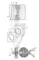
図2は、第1の実施形態に係る抽出部153による断面の抽出処理の一例を模式的に示す図である。例えば、抽出部153は、図2に示すように、検出部152によって検出された血管10の芯線30を抽出して、抽出した芯線30に沿って、芯線30に対して垂直となる複数の断面を抽出する。そして、抽出部153は、図2に示すように、血管10及びステントグラフト20の位置情報(座標情報)に基づいて、抽出した複数の断面における血管壁断面11及びステント断面21を抽出する。なお、血管10の芯線30は、例えば、ベッセルトラッキング法、或いは、血管の内部領域を細線化する方法などにより抽出される。
FIG. 2 is a diagram schematically illustrating an example of a cross-section extraction process by the
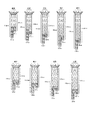
図3は、第1の実施形態に係る抽出部153による接触部分の抽出処理の一例を模式的に示す図である。図3においては、図2の処理後の処理について示す。例えば、抽出部153は、図3の(A)に示すように、抽出した断面におけるステント断面21上の点22を抽出して、血管壁断面11と外接する円の半径を算出する。そして、抽出部153は、算出した円の半径が所定の閾値(≒0)を下回った場合に点22に対してマーキングする。抽出部153は、ステント断面21上のすべての点に対して、血管壁断面11と外接する円の半径の算出、所定の閾値を用いた判定及びマーキング処理を実行する。
FIG. 3 is a diagram schematically illustrating an example of a contact portion extraction process performed by the
すべての点に対して上述した処理を実行すると、抽出部153は、図3の(B)に示すように、隣り合うマーキングされた点を結び接触部分40を抽出する。なお、図2においては、1つの断面のみが示されているが、実際には、抽出部153は、血管壁断面11及びステント断面21が含まれる全ての断面に対して上述した接触部分の抽出処理を実行する。
When the above-described processing is executed for all points, the
図4は、第1の実施形態に係る抽出部153による接触領域の抽出処理の一例を模式的に示す図である。図4においては、図3の処理後の処理について示す。例えば、抽出部153は、図4に示すように、血管壁断面11とステント断面21との接触部分40を抽出すると、断面を積層して円筒モデルを生成する。ここで、抽出部153は、図4の矢印50に示すように、円筒モデルの基準方向を決めて円筒モデルを生成する。すなわち、抽出部153は、ボリュームデータの座標における各断面の向きを揃えて積層した円筒モデルを生成する。これにより、例えば、芯線30に沿って断面を抽出する際の向きのズレを補正することができる。そして、抽出部153は、生成した円筒モデルの側面に示された接触部分40を結合した領域全体を接触領域として抽出する。
FIG. 4 is a diagram schematically illustrating an example of contact area extraction processing by the
さらに、抽出部153は、例えば、血管10の長手方向において血管10の全周囲に渡って血管10とステントグラフト20とが接触している位置のうち、ステントグラフト20の中央側の位置をエンドリークが発生する境界であるエンドリーク境界位置として抽出する。すなわち、抽出部153は、血管10とステントグラフト20との境界であるステント境界位置を抽出する。図5は、第1の実施形態に係る抽出部153によるエンドリーク境界位置の抽出処理の一例を模式的に示す図である。ここで、図5においては、図4に示す円筒モデルの展開図を示す。
Further, for example, the
例えば、抽出部153は、図5に示すように、血管とステントグラフトの接触領域41において、血管の全周囲に渡って接触している位置をエンドリーク境界位置52として抽出する。言い換えると、抽出部153は、ステントグラフトの端部がこの位置より下に移動した場合に、物理的にエンドリークが発生する位置をエンドリーク境界位置52として抽出する。また、抽出部153は、図5に示すように、血管壁断面11とステント断面21との境界であるステント境界位置51を抽出する。なお、図5に示す接触領域41は、図4に示す接触部分40が結合されたものを示す。また、図5における矢印53については後述する。
For example, as illustrated in FIG. 5, the
図1に戻って、算出部154は、血管とステントグラフトとの境界であるステント境界位置とエンドリーク境界位置との間の距離を算出する。具体的には、算出部154は、ステント境界位置とエンドリーク境界位置との最短距離を算出する。例えば、算出部154は、図5に示すように、ステント境界位置51とエンドリーク境界位置52との間の距離である境界距離53を算出する。一例を挙げると、算出部154は、図5に示すように、境界距離53として「2.7cm」を算出する。すなわち、算出部154は、エンドリークが発生するまでのステントグラフトの移動距離を算出する。
Returning to FIG. 1, the
そして、算出部154は、円筒モデルや、円筒モデルの展開図、及び境界距離などの情報を表示画像として解析結果記憶部142に格納する。例えば、算出部154は、図4に示す円筒モデルや、図5に示す展開図などを解析結果記憶部142に格納する。
Then, the
図1に戻って、表示制御部155は、ステントグラフトの端部と抽出部153によって抽出された接触領域との相対的な位置関係を示す表示画像を表示部120にて表示させるように制御する。具体的には、表示制御部155は、ステント境界位置とエンドリーク境界位置との位置関係を示す情報を表示部120にて表示させる。例えば、表示制御部155は、図5に示す円筒モデルの展開図と、境界距離とを示す表示画像を解析結果記憶部142から読み出して、表示部120にて表示させる。このとき、表示制御部155は、図4に示す血管10から円筒モデルまでの過程も同時に表示させることができる。これにより、観察者は、血管とステントグラフトの位置関係及び境界距離を容易にイメージすることができる。そして、観察者は、これらの情報から、エンドリークの発生時期を容易に予測することができる。
Returning to FIG. 1, the
なお、上述した実施形態においては、血管壁断面とステント断面の接触部分を抽出する際に、ステント断面上の点から血管壁断面までの距離に基づいて接触部分を抽出する場合について説明した。しかしながら、実施形態はこれに限定されるものではなく、例えば、血管壁断面上の点からステント断面までの距離に基づいて接触部分を抽出する場合であってもよい。 In the above-described embodiment, the case where the contact portion is extracted based on the distance from the point on the stent cross section to the blood vessel wall cross section when extracting the contact portion between the blood vessel wall cross section and the stent cross section has been described. However, the embodiment is not limited to this. For example, the contact portion may be extracted based on the distance from the point on the blood vessel wall cross section to the stent cross section.
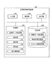
図6は、第1の実施形態に係る医用画像処理装置100による処理の手順を示すフローチャートである。図6に示すように、第1に実施形態に係る医用画像処理装置100においては、まず、画像データ取得部151が、画像データ記憶部141からボリュームデータを取得する(ステップS101)。
FIG. 6 is a flowchart illustrating a processing procedure performed by the medical
そして、検出部152が、画像データ取得部151によって取得されたボリュームデータから血管及びステントグラフトを抽出する(ステップS102)。その後、抽出部153が、検出部152によって抽出された血管とステントグラフトとの接触領域を抽出する(ステップS103)。さらに、抽出部153は、血管、ステントグラフト及び抽出した接触領域の位置情報に基づいて、ステント境界位置及びエンドリーク境界位置を抽出する(ステップS104)。
Then, the
その後、算出部154が、境界距離を算出して(ステップS105)、表示制御部155が、境界距離の情報を含む表示画像を表示部120にて表示させる(ステップS106)。
Thereafter, the
上述したように、第1の実施形態によれば、検出部152は、3次元の医用画像データに含まれる血管とステントグラフトとを検出する。そして、抽出手段は、3次元の医用画像データにおける座標に基づいて、検出部152によって検出された血管とステントグラフトとの接触領域を抽出する。そして、表示制御部155は、ステントグラフトの端部と抽出部153によって抽出された接触領域との相対的な位置関係を示す表示画像を表示部120にて表示させるように制御する。従って、第1の実施形態に係る医用画像処理装置100は、ステントグラフトと血管との接触領域と、ステント端部との位置関係の情報を観察者に対して提供することができ、ステントグラフトのエンドリークの時期を予測することを可能にする。
As described above, according to the first embodiment, the
例えば、観察者は、ステントグラフト内挿術が施術された直後の境界距離を参照して、ステントグラフトが移動した場合に、いつ頃エンドリークが発生するかを予測して、その前に、再度X線CT装置などで撮影を実行して状態を観察することができる。 For example, the observer refers to the boundary distance immediately after the stent graft insertion has been performed, predicts when the end graft will occur when the stent graft moves, and before that, again before the X-ray The state can be observed by performing imaging with a CT apparatus or the like.
また、第1の実施形態によれば、抽出部153は、血管の芯線に沿って芯線に直交する複数の断面を抽出し、抽出した複数の断面にそれぞれ含まれる血管壁の断面とステントグラフトの断面との接触部分を、血管壁及び前記ステントグラフトの断面それぞれの座標に基づいて抽出し、抽出した接触部分を結合することで接触領域を抽出する。従って、第1の実施形態に係る医用画像処理装置100は、ボリュームデータから正確に接触領域を抽出することを可能にする。
Further, according to the first embodiment, the
また、第1の実施形態によれば、抽出部153は、血管壁の断面上の点からステントグラフトの断面までの距離、又は、ステントグラフトの断面上の点から血管壁の断面までの距離が、所定の閾値を下回った部分を接触部分として抽出する。従って、第1の実施形態に係る医用画像処理装置100は、血管壁とステントグラフトとの接触部分を正確に抽出することを可能にする。
Further, according to the first embodiment, the
また、第1の実施形態によれば、抽出部153は、血管の長手方向において血管の全周囲に渡って血管とステントグラフトとが接触している位置のうち、ステントグラフトの中央側の位置をエンドリークが発生する境界であるエンドリーク境界位置として抽出する。従って、第1の実施形態に係る医用画像処理装置100は、エンドリークが発生するか否かを的確に判定することを可能にする。
In addition, according to the first embodiment, the
また、第1の実施形態によれば、算出部154は、血管と前記ステントグラフトとの境界であるステント境界位置と前記エンドリーク境界位置との間の距離を算出する。従って、第1の実施形態に係る医用画像処理装置100は、観察者に対して、エンドリークの発生を予測するための最適な情報を提供することを可能にする。
Further, according to the first embodiment, the
(第2の実施形態)
上述した第1の実施形態においては、1時点(例えば、ステントグラフト留置直後)のボリュームデータを用いてエンドリークを予測する場合について説明した。第2の実施形態では、複数の時点で収集されたボリュームデータを用いてエンドリークを予測する場合について説明する。なお、第2の実施形態に係る医用画像処理装置100においては、第1の実施形態に係る医用画像処理装置と比較して、算出部154による処理内容が異なる。以下、これを中心に説明する。
(Second Embodiment)
In the first embodiment described above, a case has been described in which end leak is predicted using volume data at one point in time (for example, immediately after placement of a stent graft). In the second embodiment, a case where end leak is predicted using volume data collected at a plurality of times will be described. Note that in the medical
第2の実施形態に係る医用画像処理装置100においては、まず、画像データ取得部151が、同一被検体から収集された時相の異なるボリュームデータを取得する。そして、検出部152が、複数のボリュームデータから血管及びステントグラフトをそれぞれ抽出する。その後、抽出部153が、複数のボリュームデータからステント境界位置及びエンドリーク境界位置をそれぞれ抽出する。
In the medical
第2の実施形態に係る算出部154は、抽出部153によって時相の異なる3次元の医用画像データからそれぞれ抽出されたステント境界位置及びエンドリーク位置の間の距離をそれぞれ算出し、算出した距離の変化に基づいて、エンドリークの時期を推定する。
The
図7は、第2の実施形態に係る算出部154による処理の一例を説明するための図である。例えば、算出部154は、図7に示すように、留置直後、1ヶ月後及び3ヶ月後のボリュームデータからそれぞれ抽出されたステント境界位置とエンドリーク境界位置とを用いて、留置直後、1ヶ月後及び3ヶ月後の境界距離をそれぞれ算出する。
FIG. 7 is a diagram for explaining an example of processing by the
そして、算出部154は、ステント境界位置の移動に起因する境界距離の変化に基づいて、エンドリーク時期を予測する。例えば、算出部154は、図7に示すように、横軸に時間、縦軸に境界距離をとったグラフに留置直後、1ヶ月後及び3ヶ月後の境界距離の値をプロットすることで、エンドリーク時期を推定する。そして、算出部154は、図7に示すグラフを表示画像として解析結果記憶部142に格納する。
Then, the
なお、上述した実施形態では、複数の時相のボリュームデータを同時に処理する場合について説明した。しかしながら、実施形態はこれに限定されるものではなく、例えば、X線CT装置によってボリュームデータが収集されるごとに、境界距離を算出して図7に示すグラフを作成してエンドリーク時期を推定する場合であってもよい。また、解析結果記憶部142によって記憶された境界距離を任意のタイミングで読み出し、図7に示すグラフを作成してエンドリーク時期を推定する場合であってもよい。
In the above-described embodiment, a case has been described in which a plurality of time phase volume data are processed simultaneously. However, the embodiment is not limited to this. For example, every time volume data is collected by the X-ray CT apparatus, the boundary distance is calculated and the graph shown in FIG. 7 is created to estimate the end leak time. It may be the case. Moreover, the boundary distance memorize | stored by the analysis result memory |
第2の実施形態に係る表示制御部155は、算出部154によって推定されたエンドリーク時期を含む表示画像を表示部120にて表示させる。例えば、表示制御部155は、解析結果記憶部142によって記憶された図7に示すグラフを読み出して、表示部120に表示させる。
The
図8は、第2の実施形態に係る医用画像処理装置100による処理の手順を示すフローチャートである。図8においては、複数の時相のボリュームデータを同時に処理する場合について示す。図8に示すように、第2に実施形態に係る医用画像処理装置100においては、まず、画像データ取得部151が、画像データ記憶部141から各時相のボリュームデータを取得する(ステップS201)。
FIG. 8 is a flowchart illustrating a processing procedure performed by the medical
そして、検出部152が、画像データ取得部151によって取得された各時相のボリュームデータから血管及びステントグラフトをそれぞれ抽出する(ステップS202)。その後、抽出部153が、検出部152によって抽出された各時相の血管とステントグラフトとの接触領域をそれぞれ抽出する(ステップS203)。さらに、抽出部153は、血管、ステントグラフト及び抽出した接触領域の位置情報に基づいて、ステント境界位置及びエンドリーク境界位置をそれぞれ抽出する(ステップS204)。
Then, the
その後、算出部154が、境界距離をそれぞれ算出して(ステップS205)、各時相の境界距離からエンドリーク時期を推定する(ステップS206)。そして、表示制御部155が、エンドリーク時期を含む表示画像を表示部120にて表示させる(ステップS207)。
Thereafter, the
上述したように、第2の実施形態によれば、抽出部153は、同一被検体から収集された時相の異なるボリュームデータからステント境界位置及びエンドリーク境界位置をそれぞれ抽出する。そして、算出部154は、抽出部153によって時相の異なるボリュームデータからそれぞれ抽出されたステント境界位置及びエンドリーク境界位置の間の距離をそれぞれ算出し、算出した距離の変化に基づいて、エンドリークの時期を推定する。従って、第2の実施形態に係る医用画像処理装置100は、観察者に対してエンドリーク時期を提供することを可能にする。
As described above, according to the second embodiment, the
(第3の実施形態)
上述した実施形態では、ステントグラフト内挿術が施術された後に収集されたボリュームデータを用いて血管とステントグラフトとの接触領域を抽出して境界距離を算出する場合について説明した。第3の実施形態では、ステントグラフトのサイズを用いて仮想的に接触領域の抽出と境界距離の算出を実行する場合について説明する。
(Third embodiment)
In the above-described embodiment, the case where the boundary distance is calculated by extracting the contact area between the blood vessel and the stent graft using the volume data collected after the stent graft insertion is performed has been described. In the third embodiment, a case will be described in which contact area extraction and boundary distance calculation are executed virtually using the size of a stent graft.
図9は、第3の実施形態に係る医用画像処理装置100の構成の一例を示す図である。ここで、第3の実施形態に係る医用画像処理装置100は、第1の実施形態に係る医用画像処理装置と比較して、新たにステント情報記憶部143を有する点と、抽出部153の処理内容が異なる。以下、これらを中心に説明する。
FIG. 9 is a diagram illustrating an example of the configuration of the medical
ステント情報記憶部143は、ステントグラフトの形状に係る種々の情報を記憶する。図10は、第3の実施形態に係るステント情報記憶部143によって記憶される情報を模式的に示す図である。例えば、ステント情報記憶部143は、図10に示すように、種々のタイプのステントグラフトの形状に係る情報を記憶する。一例を挙げると、ステント情報記憶部143は、図10に示すように、ステントの各位置における直径、全長などのステント情報を記憶する。 The stent information storage unit 143 stores various information related to the shape of the stent graft. FIG. 10 is a diagram schematically illustrating information stored in the stent information storage unit 143 according to the third embodiment. For example, the stent information storage unit 143 stores information relating to the shapes of various types of stent grafts as shown in FIG. For example, as shown in FIG. 10, the stent information storage unit 143 stores stent information such as a diameter and a total length at each position of the stent.
第3の実施形態に係る抽出部153は、検出部152によって検出された血管に対してステントグラフトを仮想的に留置した場合に、血管とステントグラフトとの仮想的な接触領域である仮想接触領域を抽出する。具体的には、抽出部153は、観察者によって選択されたステントグラフトの形状の情報をステント情報記憶部143から読み出して、読み出したステントグラフトを検出部152によって抽出された血管に留置した場合の仮想接触領域を抽出する。
The
図11は、第3の実施形態に係る抽出部153による処理の一例を説明するための図である。例えば、抽出部153は、図11に示すように、芯線30の情報を含む血管壁断面11に対して、ステントグラフトの仮想断面23を配置して仮想接触部分42を抽出する。より詳細には、抽出部153は、ステントグラフトの直径の情報から仮想断面23を取得する。そして、抽出部153は、血管壁断面11の芯線30の位置と、ステントグラフトの仮想断面23の中心の位置とを合わせるように、仮想断面23を配置する。
FIG. 11 is a diagram for explaining an example of processing by the
その後、抽出部153は、ステントグラフトの仮想断面23又は血管壁断面11上に点を設定して、血管壁とステントグラフトとの仮想的な接触部分である仮想接触部分42を抽出する。なお、仮想接触部分42の抽出方法は、第1の実施形態と同様であることから詳細な説明は省略する。そして、抽出部153は、全ての断面に対してステントグラフトを仮想的に配置して仮想接触部分42を抽出し、側面に仮想接触領域が示された円筒モデルを生成する。
Thereafter, the
第3の実施形態に係る表示制御部155は、ステントグラフトの端部と抽出部153によって抽出された仮想接触領域との相対的な位置関係を示す表示画像を表示部120にて表示させるように制御する。図12は、第3の実施形態に係る表示制御部155によって表示制御される表示画像の一例を示す図である。
The
例えば、表示制御部155は、図12に示すように、断面の情報と、円筒モデルと、円筒モデルの展開図とが示された表示画像を表示部120にて表示させる。ここで、表示部120にて表示される表示画像においては、図12に示すように、ステント境界位置からエンドリーク境界位置までの距離である境界距離「3.5cm」が示される。すなわち、第3の実施形態に係る算出部154は、抽出部153によって抽出されたステント境界位置及びエンドリーク境界位置から境界位置を算出する。
For example, as shown in FIG. 12, the
図13は、第3の実施形態に係る医用画像処理装置100による処理の手順を示すフローチャートである。図13に示すように、第1に実施形態に係る医用画像処理装置100においては、まず、画像データ取得部151が、画像データ記憶部141からボリュームデータを取得する(ステップS301)。
FIG. 13 is a flowchart illustrating a processing procedure performed by the medical
そして、検出部152が、画像データ取得部151によって取得されたボリュームデータから血管を抽出する(ステップS302)。その後、抽出部153が、ステントグラフトの形状が選択されたか否かを判定する(ステップS303)。ここで、ステントグラフトの形状が選択された場合には(ステップS303 Yes)、抽出部153は、検出部152によって抽出された血管と選択されたステントグラフトの形状の情報とから仮想接触領域を抽出する(ステップS304)。
Then, the
さらに、抽出部153は、血管、選択されたステントグラフト及び抽出した仮想接触領域の位置情報に基づいて、ステント境界位置及びエンドリーク境界位置を抽出する(ステップS305)。その後、算出部154が、境界距離を算出して(ステップS306)、表示制御部155が、境界距離の情報を含む表示画像を表示部120にて表示させる(ステップS307)。
Further, the
そして、抽出部153は、ステントグラフトの形状が変更されたか否かを判定する(ステップS308)。ここで、ステントグラフトの形状が変更された場合には(ステップS308 Yes)、抽出部153は、ステップS304に戻って、変更されたステントグラフトの形状及び血管の情報から仮想接触領域を抽出する。一方、ステントグラフトの形状が変更されなかった場合には(ステップS308 No)、医用画像処理装置100は処理を終了する。なお、ステップS303において、ステントグラフトの形状が選択されるまで、医用画像処理装置100は待機状態である(ステップS303 No)。
Then, the
上述したように、第3の実施形態によれば、抽出部153は、検出部152によって検出された血管に対してステントグラフトを仮想的に留置した場合に、血管とステントグラフトとの仮想的な接触領域である仮想接触領域を抽出する。そして、表示制御部155は、ステントグラフトの端部と抽出部153によって抽出された仮想接触領域との相対的な位置関係を示す表示画像を表示部120にて表示させるように制御する。従って、第3の実施形態に係る医用画像処理装置100は、ステントグラフト内挿術の施術前に、種々の形状のステントグラフトによるシミュレーションを実行することができ、ユーザが症例に最適なステント形状を事前に決定することを可能にする。
As described above, according to the third embodiment, when the stent graft is virtually placed on the blood vessel detected by the
(第4の実施形態)
さて、これまで第1、第2及び第3の実施形態について説明したが、上述した第1、第2及び第3の実施形態以外にも、種々の異なる形態にて実施されてよいものである。
(Fourth embodiment)
The first, second and third embodiments have been described so far, but may be implemented in various different forms other than the first, second and third embodiments described above. .
上述した第1、第2及び第3の実施形態では、ステントグラフトの1つの位置を対象とする場合について説明した。しかしながら、実施形態はこれに限定されるものではなく、例えば、ステントグラフトの複数の位置を対象とする場合であってもよい。 In the first, second, and third embodiments described above, the case where one position of the stent graft is targeted has been described. However, the embodiment is not limited to this, and may be, for example, a case where a plurality of positions of the stent graft are targeted.
図14は、第4の実施形態に係る第1の変形例を説明するための図である。例えば、第4の実施形態に係る医用画像処理装置100は、図14に示すように、複数パーツで構成されるステントグラフトの上端、下端及び接合部分における境界距離をそれぞれ算出して、表示部120に表示することができる。これにより、第4の実施形態に係る医用画像処理装置100は、パーツごとに解析して評価することを可能にする。
FIG. 14 is a diagram for explaining a first modification according to the fourth embodiment. For example, as illustrated in FIG. 14, the medical
また、上述した第1及び第3の実施形態では、エンドリーク時期を予測するための情報として、境界距離を表示する場合について説明した。しかしながら、実施形態はこれに限定されるものではなく、例えば、エンドリーク時期を予測するための情報として接触領域の幅を表示する場合であってもよい。 In the first and third embodiments described above, the case where the boundary distance is displayed as the information for predicting the end leak time has been described. However, the embodiment is not limited to this. For example, the width of the contact area may be displayed as information for predicting the end leak time.
図15は、第4の実施形態に係る第2の変形例を説明するための図である。例えば、第4の実施形態に係る医用画像処理装置100は、図15に示すように、円筒モデルの展開図において、接触領域の上境界曲線54と下境界曲線55との最短距離である接触領域幅56を算出して、表示部120に表示することが可能である。かかる場合、抽出部153が、上境界曲線54と下境界曲線55とを抽出する。そして、算出部154が、接触領域幅を算出する。
FIG. 15 is a diagram for explaining a second modification example according to the fourth embodiment. For example, as illustrated in FIG. 15, the medical
これにより、第4の実施形態に係る医用画像処理装置100は、ユーザが接触領域幅の値をもとに種々の判断を下すことを可能にする。例えば、ユーザは、接触領域幅の値をもとに次の経過観察の日程を決定することができる。すなわち、ユーザは接触領域幅の値が「0」になる前に次の経過観察を実行するように決定することができる。
Thereby, the medical
また、上述した第1、第2及び第3の実施形態では、円筒モデルの展開図において接触領域のみを表示する場合について説明した。しかしながら、実施形態はこれに限定されるものではなく、例えば、血管壁とステントグラフトとの距離が所定の値未満となる領域をさらに表示する場合であってもよい。 In the first, second, and third embodiments described above, the case where only the contact area is displayed in the development view of the cylindrical model has been described. However, the embodiment is not limited to this, and for example, a region where the distance between the blood vessel wall and the stent graft is less than a predetermined value may be displayed.
図16は、第4の実施形態に係る第3の変形例を説明するための図である。例えば、第4の実施形態に係る医用画像処理装置100は、図16に示すように、血管壁とステントとの距離が「≒0」となる接触領域と、血管壁とステントとの距離が「<0.5cm」となる領域とを異なる色で示した展開図を表示部120にて表示することも可能である。これにより、第4の実施形態に係る医用画像処理装置100は、ステントグラフトの血管壁への接触状態をより詳細に提供することを可能にする。
FIG. 16 is a diagram for explaining a third modification according to the fourth embodiment. For example, as illustrated in FIG. 16, the medical
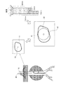
また、上述した第1、第2及び第3の実施形態では、表示画像として円筒モデルや展開図を用いる場合について説明した。しかしながら、実施形態はこれに限定されるものではなく、例えば、接触領域を画像上に重畳させて表示する場合であってもよい。 In the first, second, and third embodiments described above, the case where a cylindrical model or a developed view is used as the display image has been described. However, the embodiment is not limited to this, and may be a case where, for example, the contact area is displayed superimposed on the image.
図17は、第4の実施形態に係る第4の変形例を説明するための図である。例えば、第4の実施形態に係る医用画像処理装置100は、図17に示すように、Curved MPR画像や、Stretched MPR画像上に接触領域を重畳させた画像を表示部120にて表示させることが可能である。かかる場合には、ボリュームデータにおける接触領域の座標に基づいて、画像上に接触領域が重畳される。
FIG. 17 is a diagram for explaining a fourth modification example according to the fourth embodiment. For example, as illustrated in FIG. 17, the medical
また、上述した第1、第2及び第3の実施形態では、血管壁断面とステント断面との距離に基づいて接触部分を抽出し、抽出した接触部分を円筒モデル上で結合することにより、接触領域を抽出する場合について説明した。しかしながら、実施形態はこれに限定されるものではなく、例えば、ボリュームデータにおける血管壁の座標とステントグラフトの座標とを用いて接触領域を抽出する場合であってもよい。 In the first, second, and third embodiments described above, the contact portion is extracted based on the distance between the blood vessel wall cross section and the stent cross section, and the extracted contact portions are combined on the cylindrical model, thereby making contact. The case of extracting an area has been described. However, the embodiment is not limited to this. For example, the contact area may be extracted using the coordinates of the blood vessel wall and the coordinates of the stent graft in the volume data.
例えば、抽出部153は、ステントグラフトが留置された位置の血管の円周上に45度ずつずらした8点をプロットし、さらに血管の長手方向に10点をプロットする。そして、抽出部153は、各点における血管壁の座標及びステントグラフトの座標を抽出する。そして、抽出部153は、抽出した各点における座標間の距離を算出して、算出した距離が所定の閾値(例えば、≒0)を下回っていた場合に、血管壁とステントグラフトとが接触していると判定する。
For example, the
抽出部153は、全ての点において、上述した判定を行い、血管壁とステントグラフトとの接触点を抽出する。そして、抽出部153は、4つの接触点に囲まれた領域を接触領域として抽出する。なお、接触領域として判定する基準はユーザによって任意に設定することができる。例えば、周囲4点のうち、3点が接触点である領域を接触領域として抽出する場合であってもよい。また、例えば、周囲4点のうち3点が接触点、1点が「座標間の距離<0.5cm」である領域を接触領域として抽出する場合であってもよい。
The
以上述べた少なくともひとつの実施形態の医用画像処理装置によれば、ステントグラフトのエンドリークの時期を予測することが可能となる。 According to the medical image processing apparatus of at least one embodiment described above, it is possible to predict the end leak time of the stent graft.
本発明のいくつかの実施形態を説明したが、これらの実施形態は、例として提示したものであり、発明の範囲を限定することは意図していない。これら実施形態は、その他の様々な形態で実施されることが可能であり、発明の要旨を逸脱しない範囲で、種々の省略、置き換え、変更を行うことができる。これら実施形態やその変形は、発明の範囲や要旨に含まれると同様に、特許請求の範囲に記載された発明とその均等の範囲に含まれるものである。 Although several embodiments of the present invention have been described, these embodiments are presented by way of example and are not intended to limit the scope of the invention. These embodiments can be implemented in various other forms, and various omissions, replacements, and changes can be made without departing from the spirit of the invention. These embodiments and their modifications are included in the scope and gist of the invention, and are also included in the invention described in the claims and the equivalents thereof.
100 医用画像処理装置
150 制御部
151 画像データ取得部
152 検出部
153 抽出部
154 算出部
155 表示制御部
DESCRIPTION OF
Claims (6)
前記3次元の医用画像データにおける座標に基づいて、前記検出手段によって検出された血管とステントグラフトとの接触領域を抽出する抽出手段と、
前記ステントグラフトの端部と前記抽出手段によって抽出された接触領域との相対的な位置関係を示す表示画像を所定の表示部にて表示させるように制御する表示制御手段と、
を備え、
前記抽出手段は、前記血管の長手方向において前記血管の全周囲に渡って前記血管と前記ステントグラフトとが接触している位置のうち、前記ステントグラフトの中央側の位置をエンドリークが発生する境界であるエンドリーク境界位置として抽出することを特徴とする医用画像処理装置。 Detection means having a function of detecting blood vessels and stent grafts included in the three-dimensional medical image data;
Extraction means for extracting a contact area between the blood vessel and the stent graft detected by the detection means based on the coordinates in the three-dimensional medical image data;
Display control means for controlling the display image indicating the relative positional relationship between the end portion of the stent graft and the contact area extracted by the extraction means to be displayed on a predetermined display section;
Equipped with a,
The extraction means is a boundary where end leakage occurs at a position on the center side of the stent graft among positions where the blood vessel and the stent graft are in contact with each other over the entire circumference of the blood vessel in the longitudinal direction of the blood vessel. A medical image processing apparatus characterized by extracting as an end leak boundary position .
前記算出手段は、前記抽出手段によって時相の異なる3次元の医用画像データからそれぞれ抽出された前記ステント境界位置及び前記エンドリーク境界位置の間の距離をそれぞれ算出し、算出した距離の変化に基づいて、エンドリークの時期を推定することを特徴とする請求項4に記載の医用画像処理装置。 The extraction means extracts the stent boundary position and the endoleak boundary position from three-dimensional medical image data having different time phases collected from the same subject,
The calculation unit calculates a distance between the stent boundary position and the endoleak boundary position respectively extracted from three-dimensional medical image data having different time phases by the extraction unit, and based on the calculated change in distance. The medical image processing apparatus according to claim 4 , wherein an end leak time is estimated.
前記表示制御手段は、前記仮想的に留置したステントグラフトの端部と前記抽出手段によって抽出された仮想接触領域との相対的な位置関係を示す表示画像を所定の表示部にて表示させるように制御することを特徴とする請求項1に記載の医用画像処理装置。 The extraction unit extracts a virtual contact region that is a virtual contact region between the blood vessel and the virtually placed stent graft when the stent graft is virtually placed on the blood vessel detected by the detection unit. And
The display control unit is configured to display a display image indicating a relative positional relationship between the end portion of the virtually placed stent graft and the virtual contact region extracted by the extraction unit on a predetermined display unit. The medical image processing apparatus according to claim 1, wherein:
Priority Applications (1)
| Application Number | Priority Date | Filing Date | Title |
|---|---|---|---|
| JP2012265233A JP6087604B2 (en) | 2012-12-04 | 2012-12-04 | Medical image processing device |
Applications Claiming Priority (1)
| Application Number | Priority Date | Filing Date | Title |
|---|---|---|---|
| JP2012265233A JP6087604B2 (en) | 2012-12-04 | 2012-12-04 | Medical image processing device |
Publications (2)
| Publication Number | Publication Date |
|---|---|
| JP2014108313A JP2014108313A (en) | 2014-06-12 |
| JP6087604B2 true JP6087604B2 (en) | 2017-03-01 |
Family
ID=51029296
Family Applications (1)
| Application Number | Title | Priority Date | Filing Date |
|---|---|---|---|
| JP2012265233A Active JP6087604B2 (en) | 2012-12-04 | 2012-12-04 | Medical image processing device |
Country Status (1)
| Country | Link |
|---|---|
| JP (1) | JP6087604B2 (en) |
Families Citing this family (2)
| Publication number | Priority date | Publication date | Assignee | Title |
|---|---|---|---|---|
| JP7262923B2 (en) * | 2017-12-27 | 2023-04-24 | キヤノンメディカルシステムズ株式会社 | MEDICAL IMAGE PROCESSING APPARATUS, CONTROL METHOD THEREOF, AND PROGRAM |
| JP7286380B2 (en) | 2019-04-01 | 2023-06-05 | 国立大学法人 東京大学 | MEDICAL IMAGE PROCESSING APPARATUS AND MEDICAL IMAGE PROCESSING PROGRAM |
Family Cites Families (4)
| Publication number | Priority date | Publication date | Assignee | Title |
|---|---|---|---|---|
| US6702847B2 (en) * | 2001-06-29 | 2004-03-09 | Scimed Life Systems, Inc. | Endoluminal device with indicator member for remote detection of endoleaks and/or changes in device morphology |
| JP5358841B2 (en) * | 2008-03-10 | 2013-12-04 | 学校法人東海大学 | Stent shape optimization simulator |
| EP2344020B1 (en) * | 2008-10-14 | 2020-05-20 | Lightlab Imaging, Inc. | Stent strut detection and related measurement and display using optical coherence tomography |
| JP2011045449A (en) * | 2009-08-25 | 2011-03-10 | Toshiba Corp | Image processor and image diagnostic apparatus |
-
2012
- 2012-12-04 JP JP2012265233A patent/JP6087604B2/en active Active
Also Published As
| Publication number | Publication date |
|---|---|
| JP2014108313A (en) | 2014-06-12 |
Similar Documents
| Publication | Publication Date | Title |
|---|---|---|
| US20180345581A1 (en) | Living body tissue three-dimensional model and production method therefor | |
| US9098899B2 (en) | Determining the specific orientation of an object | |
| ES2901139T3 (en) | Blood vessel image processing equipment, blood vessel image processing program, and blood vessel image processing method | |
| Kaladji et al. | Prediction of deformations during endovascular aortic aneurysm repair using finite element simulation | |
| JP2018520816A (en) | Devices and methods for anatomical mapping of prosthetic implants | |
| JP6434171B2 (en) | Image alignment | |
| US20110306868A1 (en) | Device and method for medical image processing | |
| US11723721B2 (en) | Apparatus and method for manufacturing surgical guide, and surgical guide | |
| US20160300017A1 (en) | Method and apparatus for providing surgery-related anatomical information | |
| WO2013156546A2 (en) | Endoprosthesis leakage analysis | |
| JP6087604B2 (en) | Medical image processing device | |
| Macía et al. | Standard and fenestrated endograft sizing in EVAR planning: description and validation of a semi-automated 3D software | |
| Kobayashi et al. | Development of an image-based modeling system to investigate evolutional geometric changes of a stent graft in an abdominal aortic aneurysm | |
| JP5364334B2 (en) | Medical image processing device | |
| US9642535B2 (en) | Medical image processing apparatus and medical image processing method | |
| Wilson et al. | A novel approach to calculating small intestine length based on magnetic resonance enterography | |
| CN111317566A (en) | Planning support for interventional procedures | |
| JP5923067B2 (en) | Diagnosis support apparatus, diagnosis support method, and diagnosis support program | |
| RU2595805C2 (en) | Vessel annotator | |
| US11335017B2 (en) | Registration facility, method for registering, corresponding computer program and computer-readable storage medium | |
| JP2006042969A (en) | Medical image displaying device | |
| JP6262251B2 (en) | Spatial dimension determination device for determining a spatial dimension of a target element in an object | |
| JP5957409B2 (en) | Region extraction apparatus and method, and program | |
| KR20160012644A (en) | Method and apparatus for controlling key point matching of medical images | |
| US20210030474A1 (en) | Simulation of the deployment of an endoprosthesis in real time |
Legal Events
| Date | Code | Title | Description |
|---|---|---|---|
| A621 | Written request for application examination |
Free format text: JAPANESE INTERMEDIATE CODE: A621 Effective date: 20151027 |
|
| RD01 | Notification of change of attorney |
Free format text: JAPANESE INTERMEDIATE CODE: A7421 Effective date: 20151102 |
|
| A711 | Notification of change in applicant |
Free format text: JAPANESE INTERMEDIATE CODE: A711 Effective date: 20160513 |
|
| A977 | Report on retrieval |
Free format text: JAPANESE INTERMEDIATE CODE: A971007 Effective date: 20160831 |
|
| RD02 | Notification of acceptance of power of attorney |
Free format text: JAPANESE INTERMEDIATE CODE: A7422 Effective date: 20160928 |
|
| A131 | Notification of reasons for refusal |
Free format text: JAPANESE INTERMEDIATE CODE: A131 Effective date: 20161004 |
|
| RD04 | Notification of resignation of power of attorney |
Free format text: JAPANESE INTERMEDIATE CODE: A7424 Effective date: 20161021 |
|
| A521 | Request for written amendment filed |
Free format text: JAPANESE INTERMEDIATE CODE: A523 Effective date: 20161202 |
|
| TRDD | Decision of grant or rejection written | ||
| A01 | Written decision to grant a patent or to grant a registration (utility model) |
Free format text: JAPANESE INTERMEDIATE CODE: A01 Effective date: 20170104 |
|
| A61 | First payment of annual fees (during grant procedure) |
Free format text: JAPANESE INTERMEDIATE CODE: A61 Effective date: 20170202 |
|
| R150 | Certificate of patent or registration of utility model |
Ref document number: 6087604 Country of ref document: JP Free format text: JAPANESE INTERMEDIATE CODE: R150 |
|
| S533 | Written request for registration of change of name |
Free format text: JAPANESE INTERMEDIATE CODE: R313533 |
|
| R350 | Written notification of registration of transfer |
Free format text: JAPANESE INTERMEDIATE CODE: R350 |