JP6087352B2 - High spatial resolution optical coherence tomography rotating catheter - Google Patents
High spatial resolution optical coherence tomography rotating catheter Download PDFInfo
- Publication number
- JP6087352B2 JP6087352B2 JP2014521702A JP2014521702A JP6087352B2 JP 6087352 B2 JP6087352 B2 JP 6087352B2 JP 2014521702 A JP2014521702 A JP 2014521702A JP 2014521702 A JP2014521702 A JP 2014521702A JP 6087352 B2 JP6087352 B2 JP 6087352B2
- Authority
- JP
- Japan
- Prior art keywords
- light reflecting
- distal end
- tubular member
- bundle
- optical fiber
- Prior art date
- Legal status (The legal status is an assumption and is not a legal conclusion. Google has not performed a legal analysis and makes no representation as to the accuracy of the status listed.)
- Expired - Fee Related
Links
Images


Classifications
-
- A—HUMAN NECESSITIES
- A61—MEDICAL OR VETERINARY SCIENCE; HYGIENE
- A61B—DIAGNOSIS; SURGERY; IDENTIFICATION
- A61B5/00—Measuring for diagnostic purposes; Identification of persons
- A61B5/0059—Measuring for diagnostic purposes; Identification of persons using light, e.g. diagnosis by transillumination, diascopy, fluorescence
- A61B5/0082—Measuring for diagnostic purposes; Identification of persons using light, e.g. diagnosis by transillumination, diascopy, fluorescence adapted for particular medical purposes
- A61B5/0084—Measuring for diagnostic purposes; Identification of persons using light, e.g. diagnosis by transillumination, diascopy, fluorescence adapted for particular medical purposes for introduction into the body, e.g. by catheters
-
- A—HUMAN NECESSITIES
- A61—MEDICAL OR VETERINARY SCIENCE; HYGIENE
- A61B—DIAGNOSIS; SURGERY; IDENTIFICATION
- A61B1/00—Instruments for performing medical examinations of the interior of cavities or tubes of the body by visual or photographical inspection, e.g. endoscopes; Illuminating arrangements therefor
- A61B1/00163—Optical arrangements
- A61B1/00165—Optical arrangements with light-conductive means, e.g. fibre optics
- A61B1/00167—Details of optical fibre bundles, e.g. shape or fibre distribution
-
- A—HUMAN NECESSITIES
- A61—MEDICAL OR VETERINARY SCIENCE; HYGIENE
- A61B—DIAGNOSIS; SURGERY; IDENTIFICATION
- A61B5/00—Measuring for diagnostic purposes; Identification of persons
- A61B5/0059—Measuring for diagnostic purposes; Identification of persons using light, e.g. diagnosis by transillumination, diascopy, fluorescence
- A61B5/0062—Arrangements for scanning
- A61B5/0066—Optical coherence imaging
-
- A—HUMAN NECESSITIES
- A61—MEDICAL OR VETERINARY SCIENCE; HYGIENE
- A61B—DIAGNOSIS; SURGERY; IDENTIFICATION
- A61B5/00—Measuring for diagnostic purposes; Identification of persons
- A61B5/68—Arrangements of detecting, measuring or recording means, e.g. sensors, in relation to patient
- A61B5/6846—Arrangements of detecting, measuring or recording means, e.g. sensors, in relation to patient specially adapted to be brought in contact with an internal body part, i.e. invasive
- A61B5/6847—Arrangements of detecting, measuring or recording means, e.g. sensors, in relation to patient specially adapted to be brought in contact with an internal body part, i.e. invasive mounted on an invasive device
- A61B5/6852—Catheters
-
- Y—GENERAL TAGGING OF NEW TECHNOLOGICAL DEVELOPMENTS; GENERAL TAGGING OF CROSS-SECTIONAL TECHNOLOGIES SPANNING OVER SEVERAL SECTIONS OF THE IPC; TECHNICAL SUBJECTS COVERED BY FORMER USPC CROSS-REFERENCE ART COLLECTIONS [XRACs] AND DIGESTS
- Y10—TECHNICAL SUBJECTS COVERED BY FORMER USPC
- Y10T—TECHNICAL SUBJECTS COVERED BY FORMER US CLASSIFICATION
- Y10T29/00—Metal working
- Y10T29/49—Method of mechanical manufacture
- Y10T29/49826—Assembling or joining
Landscapes
- Health & Medical Sciences (AREA)
- Life Sciences & Earth Sciences (AREA)
- Physics & Mathematics (AREA)
- Surgery (AREA)
- Engineering & Computer Science (AREA)
- Animal Behavior & Ethology (AREA)
- Biomedical Technology (AREA)
- Heart & Thoracic Surgery (AREA)
- Medical Informatics (AREA)
- Molecular Biology (AREA)
- Biophysics (AREA)
- Pathology (AREA)
- General Health & Medical Sciences (AREA)
- Public Health (AREA)
- Veterinary Medicine (AREA)
- Optics & Photonics (AREA)
- Nuclear Medicine, Radiotherapy & Molecular Imaging (AREA)
- Radiology & Medical Imaging (AREA)
- Investigating Or Analysing Materials By Optical Means (AREA)
- Endoscopes (AREA)
Description
発明の背景
[0001]本発明は、概して走査型イメージング装置に関し、より具体的には、光干渉断層撮影法などで用いる高空間分解能回転カテーテルに関する。
Background of the Invention
[0001] The present invention relates generally to scanning imaging devices, and more specifically to high spatial resolution rotating catheters used in optical coherence tomography and the like.
[0002]試料に反射した光が基準ビームと干渉すると、干渉信号の周波数から光が反射された深さが分かる。この技法がイメージングに用いられており、光干渉断層撮影法(OCT)として知られる。OCTは、光散乱媒質(例えば生物組織)内部の超高品質マイクロメータ分解能三次元画像の取得を可能にする光信号取得及び処理方法である。OCT並びに他の干渉計型イメージング及びレンジングシステムでは、また他のイメージングモダリティ又は治療用光源の照射にも、走査型イメージングプローブが用いられる。例えば、全体として参照により本明細書に援用される米国特許第6,891,984号を参照のこと。 [0002] When the light reflected by the sample interferes with the reference beam, the depth at which the light is reflected is known from the frequency of the interference signal. This technique is used for imaging and is known as optical coherence tomography (OCT). OCT is an optical signal acquisition and processing method that enables acquisition of ultra-high quality micrometer resolution three-dimensional images inside a light scattering medium (eg, biological tissue). In OCT and other interferometric imaging and ranging systems, scanning imaging probes are also used to illuminate other imaging modalities or therapeutic light sources. See, for example, US Pat. No. 6,891,984, which is incorporated herein by reference in its entirety.
[0003]OCTイメージング用の典型的なファイバ回転プローブは、ファイバGRIN(Gradient-Index:屈折率分布型)レンズとマイクロプリズムとを備える。マイクロプリズムを使用する欠点は、出射面が曲面状である点である。この曲面が円柱レンズとして作用し、レーザビーム品質が低下する。焦点は、円形というよりむしろ楕円形である。この問題は、ファイバの曲面を研磨して平面にすれば解決するが、しかし機械加工が極めて難題となり得る。ファイバGRINレンズに取り付けられるファイバサイズのマイクロプリズム(例えば、直径約0.125mm)は大量生産に適さないため、高額な機械加工費もさらなる課題である。また、研磨されたマイクロプリズムが完全な内部反射を達成するには、研磨された面を保護するための一種のエアバッグを形成するクリアなチュービングが必要である。別の欠点は、円柱レンズ効果に起因する光学収差のバランスをとるため、プリズムとカテーテルの内側シースとの間の空間を占める流体が必要な点である。例えば、米国特許出願公開第2011/0137124号を参照のこと。そのため、カテーテルの固定部品の遠位端を開放しなければならず、塵埃に汚染され易くなる。 [0003] A typical fiber rotating probe for OCT imaging comprises a fiber GRIN (Gradient-Index) lens and a microprism. The drawback of using microprisms is that the exit surface is curved. This curved surface acts as a cylindrical lens, and the laser beam quality is degraded. The focus is elliptical rather than circular. This problem can be solved by polishing the curved surface of the fiber to a flat surface, but machining can be extremely difficult. A fiber-sized microprism (for example, a diameter of about 0.125 mm) that is attached to the fiber GRIN lens is not suitable for mass production, so expensive machining costs are a further issue. Also, in order for the polished microprism to achieve complete internal reflection, clear tubing that forms a type of airbag to protect the polished surface is required. Another drawback is that a fluid occupying the space between the prism and the inner sheath of the catheter is required to balance the optical aberrations due to the cylindrical lens effect. See, for example, US Patent Application Publication No. 2011/0137124. Therefore, the distal end of the fixed part of the catheter has to be opened, and it becomes easy to be contaminated with dust.
[0004]或いは、ファイバGRINレンズとマイクロミラーとを使用したOCTイメージング用のファイバ回転プローブもまた、一般的な設計である。マイクロプリズムの代わりにマイクロミラーを使用する一つの利点は、円柱レンズ効果がないことである。しかしながら、小型のマイクロミラーは市販されておらず、各マイクロミラーを研磨及び被覆して高反射面を提供するための加工費が極めて高いため、高額な加工費は依然として課題である。現在、マイクロミラーは直径約0.5mmである。これまで、直径が最大約0.25mmのマイクロミラーの作製が成功したことはない。 [0004] Alternatively, fiber rotating probes for OCT imaging using fiber GRIN lenses and micromirrors are also common designs. One advantage of using micromirrors instead of microprisms is that there is no cylindrical lens effect. However, since the small micromirrors are not commercially available and the processing costs for polishing and coating each micromirror to provide a highly reflective surface are very high, high processing costs remain a challenge. Currently, micromirrors are about 0.5 mm in diameter. So far, the production of micromirrors with a maximum diameter of about 0.25 mm has never been successful.
発明の概要
[0005]本発明の例示的実施形態は、光干渉断層撮影法などで用いる高空間分解能回転カテーテルのための装置及び方法を提供する。回転カテーテルは、固定部品に対して回転する回転部品を有する。回転部品の遠位端には、ファイバプローブが配置される光学先端がある。ファイバプローブは、GRINレンズから離間された角度付きマイクロミラーを備える。マイクロミラーは、典型的には約35°〜45°の角度の傾斜面を有し、GRINレンズからの長手方向の光を回転部品の長手方向軸から外側へと横方向又は半径方向に反射する。回転部品が回転すると、この反射光ビームが周方向に回転する。マイクロミラーの使用により、光学収差が最小限となる(理論的には収差がなくなる)。結果として、光学収差のバランスをとるための流体が不要となり、従って固定部品の遠位端を封止できるため、血液がファイバプローブの光学窓を塞ぐことを防ぎ、塵埃による血液の汚染を防ぐことができる。さらに、本発明は、複数のマイクロミラーを、より大きい有効横寸法を提供するバンドルとして製造するプロセスを用いる。バンドルは、研磨及び被覆される長手部材を少なくとも5本有する。バンドルは、好ましくは数十本の長手部材を有し、より好ましくは100本を超える長手部材を有する。この製造プロセスにより、直径が最大で約0.25mmの、一定の角度で傾斜した高反射率の光反射面を有するマイクロミラーを作製することが可能となる。
Summary of the Invention
[0005] Exemplary embodiments of the present invention provide an apparatus and method for a high spatial resolution rotating catheter for use in optical coherence tomography and the like. The rotating catheter has a rotating part that rotates relative to a stationary part. At the distal end of the rotating part is an optical tip on which the fiber probe is placed. The fiber probe comprises an angled micromirror spaced from the GRIN lens. The micromirror typically has an inclined surface with an angle of about 35 ° to 45 ° and reflects the longitudinal light from the GRIN lens laterally or radially outward from the longitudinal axis of the rotating component. . When the rotating component rotates, the reflected light beam rotates in the circumferential direction. The use of micromirrors minimizes optical aberrations (theoretically no aberrations). As a result, no fluid is needed to balance the optical aberrations, and therefore the distal end of the fixed part can be sealed, preventing blood from blocking the fiber probe's optical window and preventing contamination of the blood by dust. Can do. Furthermore, the present invention uses a process of manufacturing a plurality of micromirrors as a bundle that provides a larger effective lateral dimension. The bundle has at least five longitudinal members that are polished and coated. The bundle preferably has several tens of longitudinal members, more preferably more than 100 longitudinal members. This manufacturing process makes it possible to produce a micromirror having a high-reflectance light reflecting surface inclined at a constant angle and having a diameter of about 0.25 mm at the maximum.
[0006]本発明のある態様において、光干渉断層撮影(OCT)回転カテーテルは、カテーテル本体と;カテーテル本体に配置されるチューブ状部材であって、チューブ状部材が近位端と遠位端との間に延在する中空内部を有し、遠位端と近位端との間に長手方向軸が長手方向に延在し、チューブ状部材が長手方向軸の周りに回転自在である、チューブ状部材と;チューブ状部材の中空内部に沿って延在する光ファイバであって、チューブ状部材の遠位端の近傍位置に光ファイバ遠位端を有することにより光ファイバ遠位端を通ってチューブ状部材の遠位端に向かう光を誘導する光ファイバと;チューブ状部材の中空内部に光ファイバ遠位端より遠位に配置された、且つチューブ状部材と共に長手方向軸の周りに回転するように構成された光反射部材であって、光反射部材が光反射面を備え、光反射面は、光ファイバ遠位端から離間されてそれに対面しており、且つ光ファイバからの光を長手方向軸に対して所定の角度で半径方向に反射するように傾斜していて、この反射光は、光反射部材が長手方向軸の周りに回転することによって周方向に回転する、光反射部材とを含む。光反射部材は直径が最大で約0.25mmであり、光反射面は、研磨され、且つ光反射フィルムで被覆される。 [0006] In one aspect of the invention, an optical coherence tomography (OCT) rotating catheter includes a catheter body; a tubular member disposed on the catheter body, the tubular member having a proximal end and a distal end. A tube having a hollow interior extending therebetween, the longitudinal axis extending longitudinally between the distal and proximal ends, and the tubular member being rotatable about the longitudinal axis An optical fiber extending along the hollow interior of the tubular member, and having an optical fiber distal end at a location proximate to the distal end of the tubular member, through the optical fiber distal end An optical fiber for directing light toward the distal end of the tubular member; disposed in the hollow interior of the tubular member distal to the distal end of the optical fiber and rotated about the longitudinal axis with the tubular member Light reflection configured as The light reflecting member includes a light reflecting surface, the light reflecting surface is spaced apart from the optical fiber distal end and faces the optical fiber, and the light from the optical fiber has a predetermined axis with respect to the longitudinal axis. The reflected light includes a light reflecting member that is inclined to reflect at an angle in a radial direction and that rotates in a circumferential direction as the light reflecting member rotates about a longitudinal axis. The light reflecting member has a maximum diameter of about 0.25 mm, and the light reflecting surface is polished and covered with a light reflecting film.
[0007]一部の実施形態では、光反射部材は、金属材料、繊維材料、及びガラス材料からなる群から選択される材料で作製される。好ましい一実施形態において、材料はステンレス鋼である。光反射フィルムは、アルミニウム、銀、金、及び誘電体被覆材料からなる群から選択される材料を含む。光反射部材及び光ファイバ遠位端は、チューブ状部材と共に長手方向軸の周りに回転するようにチューブ状部材に取り付けられ;及びチューブ状部材はカテーテル本体に対して回転自在であり、カテーテル本体はチューブ状部材の遠位端より遠位にある遠位端を有し、及びカテーテル本体の遠位端は封止される。チューブ状部材及びカテーテルは少なくとも光反射部材の近傍領域で光学的に透明であり、光反射面からの反射光がそこを通り抜けることが可能である。 [0007] In some embodiments, the light reflecting member is made of a material selected from the group consisting of a metallic material, a fiber material, and a glass material. In a preferred embodiment, the material is stainless steel. The light reflecting film includes a material selected from the group consisting of aluminum, silver, gold, and a dielectric coating material. The light reflecting member and the optical fiber distal end are attached to the tubular member for rotation about the longitudinal axis with the tubular member; and the tubular member is rotatable relative to the catheter body, The distal end of the tubular member is distal to the distal end, and the distal end of the catheter body is sealed. The tubular member and the catheter are optically transparent at least in the vicinity of the light reflecting member, and the reflected light from the light reflecting surface can pass therethrough.
[0008]具体的な実施形態において、OCT回転カテーテルは、光ファイバの遠位端に結合された第1の端部を有し且つ第2の端部を有するビームエキスパンダであって、光ファイバのファイバコアから出射する光ビームを第1の端部から第2の端部に通過させ、第1の端部から拡大して第2の端部でより大きいビームサイズにすることが可能なビームエキスパンダをさらに備える。屈折率分布型ファイバレンズがビームエキスパンダの第2の端部に結合され、ビームエキスパンダから光ビームを受け取り、その光ビームを集束させる。屈折率分布型ファイバレンズは光反射部材より近位にあり、光反射面から離間される。光ファイバは単一モードファイバであり、ビームエキスパンダはコア無しファイバ又はステップインデックス型多モードファイバを含む。屈折率分布型ファイバレンズはガラスクラッド又は空気に取り囲まれたコアを有し、このコアは、屈折率分布型ファイバレンズの軸からの半径方向距離に応じて屈折率がクラッドに向かって半径方向外側に低下するように変化し、及び屈折率分布型ファイバレンズのコアは、ビームエキスパンダの外径以上の直径を有する。屈折率分布型ファイバレンズは、屈折率分布型ファイバレンズの軸からの半径方向距離に応じて屈折率が半径方向外側に低下するように変化し、及び屈折率分布型ファイバレンズは、ビームエキスパンダの外径以上の直径を有する。 [0008] In a specific embodiment, the OCT rotating catheter is a beam expander having a first end coupled to the distal end of the optical fiber and having a second end, the optical fiber comprising: A beam capable of passing a light beam emitted from the fiber core from the first end to the second end and expanding from the first end to a larger beam size at the second end An expander is further provided. A graded index fiber lens is coupled to the second end of the beam expander to receive the light beam from the beam expander and focus the light beam. The gradient index fiber lens is proximal to the light reflecting member and is spaced from the light reflecting surface. The optical fiber is a single mode fiber and the beam expander includes a coreless fiber or a step index type multimode fiber. The gradient index fiber lens has a core surrounded by a glass clad or air, and this core has a refractive index radially outward toward the cladding depending on the radial distance from the axis of the gradient index fiber lens. And the core of the gradient index fiber lens has a diameter greater than or equal to the outer diameter of the beam expander. The gradient index fiber lens changes such that the refractive index decreases radially outward according to the radial distance from the axis of the gradient index fiber lens, and the gradient index fiber lens is a beam expander. It has a diameter equal to or greater than the outer diameter.
[0009]一部の実施形態では、固定シャフトチューブ状部材は、少なくとも光反射部材の近傍領域で光学的に透明であり、光反射面からの反射光がそこを通り抜けることが可能である。チューブ状部材はカテーテル本体に対して回転自在であり、チューブ状部材の外表面とカテーテル本体の内表面との間に約0.25mm未満の間隙が提供される。 [0009] In some embodiments, the fixed shaft tubular member is optically transparent at least in the vicinity of the light reflecting member, allowing reflected light from the light reflecting surface to pass therethrough. The tubular member is rotatable with respect to the catheter body, and a gap of less than about 0.25 mm is provided between the outer surface of the tubular member and the inner surface of the catheter body.
[0010]本発明の別の態様は、光干渉断層撮影(OCT)回転カテーテルの形成方法に関する。この方法は、カテーテル本体にチューブ状部材を置くステップであって、チューブ状部材が近位端と遠位端との間に延在する中空内部を有し、遠位端と近位端との間に長手方向軸が長手方向に延在し、チューブ状部材が長手方向軸の周りに回転自在である、ステップと;チューブ状部材の中空内部に沿って延在する光ファイバであって、チューブ状部材の遠位端の近傍位置に光ファイバ遠位端を有することにより光ファイバ遠位端を通ってチューブ状部材の遠位端に向かう光を誘導する光ファイバを提供するステップと;直径が最大で約0.25mmの光反射部材を形成するステップと;チューブ状部材と共に長手方向軸の周りに回転するように構成された光反射部材を、チューブ状部材の中空内部に光ファイバ遠位端より遠位に位置決めするステップであって、光反射部材が光反射面を備え、光反射面は、光ファイバ遠位端から離間されてそれに対面しており、且つ光ファイバからの光を長手方向軸に対して所定の角度で半径方向に反射するように傾斜していて、この反射光は、光反射部材が長手方向軸の周りに回転することによって周方向に回転する、ステップとを含む。光反射部材を形成するステップは、バンドルの一端に露出した面を有する少なくとも5本の長手部材のバンドルを形成するステップと、これらの長手部材;バンドルの一端における長手部材の露出した面をまとめて研磨するステップと;長手部材の研磨した面を光反射フィルムで被覆するステップと;バンドルを分離することにより、被覆された面を光反射面として有する光反射部材として各長手部材を提供するステップとを含む。 [0010] Another aspect of the invention relates to a method of forming an optical coherence tomography (OCT) rotating catheter. The method includes placing a tubular member on a catheter body, the tubular member having a hollow interior extending between a proximal end and a distal end, and having a distal end and a proximal end. An optical fiber extending along a hollow interior of the tubular member, with a longitudinal axis extending longitudinally therebetween and the tubular member being rotatable about the longitudinal axis; Providing an optical fiber for directing light through the optical fiber distal end toward the distal end of the tubular member by having the optical fiber distal end at a location proximate to the distal end of the tubular member; Forming a light reflecting member having a maximum of about 0.25 mm; a light reflecting member configured to rotate about a longitudinal axis with the tubular member; and a distal end of the optical fiber in the hollow interior of the tubular member Position more distally A light reflecting member having a light reflecting surface, the light reflecting surface being spaced apart from and facing the optical fiber distal end, and light from the optical fiber at a predetermined axis relative to the longitudinal axis; The reflected light includes a step of rotating in a circumferential direction by rotating the light reflecting member about a longitudinal axis. The step of forming the light reflecting member includes the step of forming a bundle of at least five longitudinal members having a surface exposed at one end of the bundle and the exposed members of the longitudinal member at one end of the bundle. Polishing; coating the polished surface of the longitudinal member with a light reflecting film; separating each bundle to provide each longitudinal member as a light reflecting member having the coated surface as the light reflecting surface; including.
[0011]一部の実施形態では、この方法は、光反射部材及び光ファイバ遠位端を、カテーテル本体に対して長手方向軸の周りにチューブ状部材と共に回転するようにチューブ状部材に取り付けるステップと、チューブ状部材の遠位端より遠位にあるカテーテル本体の遠位端を封止するステップとをさらに含む。 [0011] In some embodiments, the method includes attaching the light reflecting member and the optical fiber distal end to the tubular member for rotation with the tubular member about a longitudinal axis relative to the catheter body. And sealing the distal end of the catheter body distal to the distal end of the tubular member.
[0012]この発明の別の態様は、光反射面を有する光反射部材を提供する方法に関する。この方法は、バンドルの一端に露出した面を有する少なくとも5本の長手部材のバンドルを形成するステップと、これらの長手部材;バンドルの一端における長手部材の露出した面をまとめて研磨するステップと;長手部材の研磨した面を光反射フィルムで被覆するステップと;バンドルを分離することにより、被覆された面を光反射面として有する光反射部材として各長手部材を提供するステップとを含む。 [0012] Another aspect of the invention relates to a method for providing a light reflecting member having a light reflecting surface. The method includes forming a bundle of at least five longitudinal members having an exposed surface at one end of the bundle; and the longitudinal members; polishing the exposed surface of the longitudinal member at one end of the bundle together; Coating the polished surface of the longitudinal member with a light reflecting film; and separating each bundle to provide each longitudinal member as a light reflecting member having the coated surface as the light reflecting surface.
[0013]一部の実施形態では、長手部材は、各々、直径が最大で約0.25mmである。バンドルは少なくとも100本の長手部材を有する。 [0013] In some embodiments, the elongate members are each up to about 0.25 mm in diameter. The bundle has at least 100 longitudinal members.
[0014]以下の具体的な実施形態の詳細な説明に鑑みて、本発明のこれらの及び他の特徴及び利点が当業者に明らかとなるであろう。 [0014] These and other features and advantages of the present invention will be apparent to those skilled in the art in view of the following detailed description of specific embodiments.
発明の詳細な説明
[0029]以下の発明の詳細な説明では、本開示の一部をなす添付の図面が参照され、それらの図面において、本発明を実施し得る例示的実施形態が、限定ではなく、例示として示される。図面では、類似した符号がいくつかの図にわたり実質的に同様の構成要素を示す。さらに、この詳細な説明は、以下に記載するとおり、且つ図面に例示するとおり、様々な例示的実施形態を提供するものの、本発明は本明細書に記載及び例示される実施形態に限定されるものではなく、当業者に公知であろうとおり、又は当業者に公知となるであろうとおり、他の実施形態に拡張され得ることに留意しなければならない。本明細書において「一実施形態」、「この実施形態」、又は「これらの実施形態」と言及するのは、その実施形態に関連して記載される特定の特徴、構造、又は特性が本発明の少なくとも一つの実施形態に包含されることを意味し、本明細書の各所にこれらの語句が出現するからといって、必ずしも全てが同じ実施形態を指すわけではない。加えて、以下の詳細な説明では、本発明の十分な理解を提供するため、数多くの具体的な詳細が示される。しかしながら、当業者には、本発明の実施にこれらの具体的な詳細が全て必要なわけではないことは明らかであろう。他の状況では、本発明が不必要に曖昧となることがないように、周知されている構造、材料、回路、プロセス及びインタフェースについては詳細には記載しておらず、及び/又はブロック図の形式で示すこともある。
Detailed Description of the Invention
[0029] In the following detailed description of the invention, reference is made to the accompanying drawings that form a part hereof, and in which are shown by way of illustration, not limitation, exemplary embodiments in which the invention may be practiced. It is. In the drawings, like numerals indicate substantially similar components throughout the several views. Moreover, while this detailed description provides various exemplary embodiments as described below and illustrated in the drawings, the present invention is limited to the embodiments described and illustrated herein. It should be noted that other embodiments may be extended as would be known to those skilled in the art or known to those skilled in the art. References herein to "one embodiment", "this embodiment", or "these embodiments" refer to specific features, structures, or characteristics described in connection with that embodiment. These terms are not necessarily meant to all refer to the same embodiment, even if they appear anywhere in the specification. In addition, in the following detailed description, numerous specific details are set forth in order to provide a thorough understanding of the present invention. However, it will be apparent to one skilled in the art that not all of these specific details are required to practice the present invention. In other situations, well-known structures, materials, circuits, processes, and interfaces have not been described in detail and / or in the block diagram so as not to unnecessarily obscure the present invention. It may be indicated in a format.
[0030]以下の説明では、相対的な向き及び位置の用語、例えば水平、垂直、左、右、上及び下といった用語が用いられる。これらの用語は、二次元配置における、その配置の所与の向きに対する相対的な方向及び位置を指すことは理解されるであろう。配置の異なる向きについては、同じ物体又は操作が、異なる相対的な向き及び位置の用語を用いて記載され得る。 [0030] In the following description, terms of relative orientation and position are used, such as horizontal, vertical, left, right, top and bottom. It will be understood that these terms refer to the direction and position of a two-dimensional arrangement relative to a given orientation of the arrangement. For different orientations of the arrangement, the same object or operation may be described using different relative orientation and position terms.
[0031]本発明の例示的実施形態は、以下にさらに詳細に記載するとおり、光干渉断層撮影法などで用いる高空間分解能回転カテーテルのための装置及び方法を提供する。 [0031] Exemplary embodiments of the present invention provide devices and methods for high spatial resolution rotating catheters for use in optical coherence tomography and the like, as described in further detail below.
[0032]1.回転カテーテル組立体
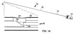
[0033]図1Aは、本発明の実施形態に係る回転カテーテルの回転部品の概略図である。回転部品10は、ファイバコネクタ12に結合された近位端を有する。回転部品10の近位部分は、好ましくはニチノールなどの直線状の可撓性材料で作製されるチュービング14である。回転部品10の遠位部分はトルクコイル16である。近位チュービング14はファイバコネクタ12及びトルクコイル16に接着されるか、レーザ溶接されるか、又は他の方法で固着され得る。回転部品10の遠位端には光学先端18があり、そこにファイバプローブ20が配置される。ファイバプローブ20は、GRINレンズ24から離間された角度付きマイクロミラー22を備える。以下にさらに詳細に記載するとおり、ファイバコネクタ12から延在する光ファイバによって出射される光ビームはGRINレンズ24を用いて集束され、ここで光ファイバの端末とGRINレンズ24との間のビームエキスパンダの助けにより、GRINレンズ単独の焦点距離(例えば、約1.8〜2.0mmの焦点距離)と比べて実質的に長い焦点距離が達成される。マイクロミラー22は、典型的には約35°〜45°の角度の傾斜面を有し、GRINレンズ24からの長手方向の光を回転部品10の長手方向軸から外側へと横方向又は半径方向に反射する。回転部品10が回転すると、この反射光ビームが周方向に回転する。図1Aに示される具体的な実施形態では、光学先端18は、光学窓を提供するクリアなチュービング部分34を備えたステンレス鋼回転チュービング32を有する。この光学窓は光学的に透明であり、マイクロミラー22に反射した光ビームがそこを通り抜けて標的組織に至り、マイクロミラー22を経て単一モードファイバに戻ることを可能にする。
[0032] 1. Rotating catheter assembly
[0033] FIG. 1A is a schematic view of a rotating component of a rotating catheter according to an embodiment of the present invention. The rotating
[0034]図1Bは、図1Aの回転カテーテルの回転部品10の別の概略図である。ファイバコネクタ12は回転コネクタハウジング38の中に装着される。回転ハウジング38は、長手方向軸の周りに回転する回転部品10の一構成要素である。
[0034] FIG. 1B is another schematic view of the
[0035]図1Cは、本発明の実施形態に係る回転カテーテルの固定部品の概略図である。固定シャフト40は、固定コネクタハウジング42と、大直径の近位チュービング44と、長い遠位チュービング46とを備える。遠位チュービング46は、好ましくは光学的に透明であるため光がそこを通り抜けることができ、FEP(フッ化エチレンプロピレン)などで作製され得る。回転コネクタハウジング38が固定コネクタハウジング42の内側にあり、回転部品の近位チュービング14が固定部品の近位チュービング44の内側にあり、且つトルクコイル16が透明な遠位チュービング46の内側にあるようにして、回転部品10が固定部品40の内側に装着される。概して、回転部品10と固定部品40との対応する構成要素間に小さい間隙(例えば約0.25mm未満)が提供され、これにより回転部品10が固定部品40に対して長手方向軸の周りに回転することが可能となる。固定部品40の遠位端48は、回転部品10の光学先端18の近傍に位置して、且つそれより遠位にあり、好ましくは封止されることで、血液がクリアなチュービング部分34の光学窓を塞ぐことを防ぎ、塵埃による血液の汚染を防ぐ。固定部品40の封止された遠位端48と回転部品10の遠位先端18との間には、約25mm以下の間隙がある。
[0035] FIG. 1C is a schematic view of a fixed part of a rotating catheter according to an embodiment of the present invention.
[0036]図1Dは、回転カテーテルのファイバコネクタ組立体の斜視図である。上述のとおり、回転部品10が固定部品40の内側に挿入される。回転コネクタハウジング38が固定コネクタハウジング42の内側にある。回転コネクタハウジング38はファイバコネクタ12に取り付けられ、これらは共に回転する。回転コネクタハウジング38と固定コネクタハウジング42との間には、小さい隙間がある。
[0036] FIG. 1D is a perspective view of a fiber connector assembly of a rotating catheter. As described above, the rotating
[0037]図2Aは、本発明の実施形態に係る回転カテーテルの構成要素としてのファイバプローブの概略立面図である。図2Bは、図2Aのファイバプローブの部分断面図である。図1Aに関連して上記に考察したとおり、ファイバプローブ20は回転部品10の光学先端18に配置される。ファイバコネクタ12から延在する光ファイバ50によって出射される光ビームはGRINレンズ24を用いて集束され、ここで光ファイバ50の端末とGRINレンズ24と間のビームエキスパンダ54の助けにより、マイクロミラー22に向かう実質的な焦点距離が達成される。一般に、GRINレンズ24は、GRINレンズ24の軸からの半径方向距離に応じて屈折率が半径方向外側に低下するように変化し、及びビームエキスパンダ54の外径以上の直径を有する。図示される実施形態では、GRINレンズ24はガラスクラッド又は空気に取り囲まれたコアを有し、このコアは、GRINレンズ24の軸からの半径方向距離に応じて屈折率がクラッドに向かって半径方向外側に低下するように変化する。GRINレンズ24のコアは、ビームエキスパンダ54の外径以上の直径を有する。ビームエキスパンダ54は、光ファイバ50の遠位端に結合される第1の端部を有し且つ第2の端部を有して、光ファイバ50のファイバコアから出射される光ビームを第1の端部から第2の端部に通過させ、第1の端部から拡大して第2の端部でより大きいビームサイズにすることが可能である。具体的な実施形態において、ビームエキスパンダ54はコア無しファイバ又はステップインデックス型多モードファイバ(SI−MMF)を含む。図2Bでは、マイクロミラー22は35°〜45°の傾斜面を有し、GRINレンズ24からの長手方向の光を回転部品10の長手方向軸から外側へと横方向又は半径方向に反射する。回転部品10が回転すると、この反射光ビームが周方向に回転する。光学先端18は、好ましくは丸い遠位端60を有して回転摩擦を低減する。ファイバプローブ20の作製及び構成についてのさらなる詳細は、以下に記載する。
[0037] FIG. 2A is a schematic elevation view of a fiber probe as a component of a rotating catheter according to an embodiment of the present invention. 2B is a partial cross-sectional view of the fiber probe of FIG. 2A. As discussed above in connection with FIG. 1A, the
[0038]光ファイバ50は、接着剤56、レーザ溶接などによってトルクコイル16の遠位端部分に取り付けられる。1つ以上の開口又は窓58を用いて接着剤56が塗布される。ファイバプローブ20の構成要素(マイクロミラー22及びGRINレンズ24)は、接着剤62などによってステンレス鋼チュービング32に取り付けられる。1つ以上の開口又は窓64を用いて接着剤62が塗布される。マイクロミラー22に反射した光ビームを出射させるため、一つの光学窓66が提供される。回転チュービング32は、具体的な実施形態において約5mmの長さを有し、他の何らかの金属又はファイバプローブ20の構成要素を支持するのに十分に強力な材料で作製され得る。マイクロミラー22に反射した光ビームが通り抜けることのできるクリアなチュービング部分34を提供する一つの方法は、全ての開口又は窓58、64、66にわたって薄いクリアな熱収縮チュービングの部分片を使用することである。
[0038] The
[0039]2.マイクロミラー
[0040]図3Aは、図2Aのファイバプローブの構成要素としての角度付きマイクロミラーの立面図である。マイクロミラー22は光反射部材であり、金属材料、繊維材料、又はガラス材料などの様々な材料で作製することができる。好ましい一実施形態において、材料はステンレス鋼である。傾斜した光反射面は研磨されて光反射フィルムで被覆され、光反射フィルムは、好ましくは高反射性である。例としては、アルミニウム、銀、及び金が挙げられる。可能な代替的反射性被覆としては、フッ化マグネシウム、フッ化カルシウム、酸化アルミニウム、二酸化ケイ素、及び二酸化チタンなどの誘電体被覆が挙げられる。マイクロミラー22は、典型的には平均長さが約0.5〜1mm及び直径が約0.1〜0.2mmである。この平均長さは、長手方向軸に沿った長さである;光反射面が傾斜しているため、実際の長さは長手方向軸から半径方向に変化する。マイクロミラー22の長手方向寸法は横寸法より実質的に大きい(例えば、約2.5〜10の比)。
[0039] 2. Micro mirror
[0040] FIG. 3A is an elevation view of an angled micromirror as a component of the fiber probe of FIG. 2A. The
[0041]図3Bは、本発明の実施形態に係る製造プロセスにおいて研磨され、且つ高反射率フィルムで被覆されたマイクロミラーのバンドルの立面図である。マイクロミラー22は小型であり(直径約0.25mm未満、典型的には直径約0.1〜0.2mm)、且つ長手方向寸法と比べて横寸法が小さいため、個々のマイクロミラーを研磨及び被覆して製造することは困難である。この発明の態様に係る解決法は、複数のマイクロミラーを、より大きい有効横寸法を提供するバンドルとして製造することである。バンドルが、研磨及び被覆される長手部材又は円筒形部材を少なくとも5本有することが、決定的に重要である。バンドルは、好ましくは数十本の長手部材を有し、より好ましくは100本を超える長手部材を有する。長手部材は、典型的には長さ約25mmであり、バンドル端部の研磨及び被覆が完了した後、加工されたバンドル端部で約0.5〜1mmの平均長さに切断される。
[0041] FIG. 3B is an elevation view of a bundle of micromirrors polished in a manufacturing process and coated with a high reflectivity film according to an embodiment of the present invention. Since the
[0042]図4は、本発明の実施形態に係るマイクロミラーの製造プロセスを示すフロー図の例である。ステップ402では、少なくとも5本の長手部材のバンドルが形成される。バンドルの一端に露出した面を有する長手部材。長手部材の例としては、ステンレス鋼線、ガラスロッド、及びポリイミド繊維が挙げられる。バンドルを形成するため、熱収縮チュービングなどを用いて長手部材をくるむことができる。加えて、長手部材を一時的に互いに接着又はその他固着してもよく、互いに動かないようにすることで、マイクロミラーに適切な角度をなす反射面を作り出す効果的な研磨及び被覆を確実にしてもよい。ステップ404は、バンドルの一端における長手部材の露出した面をまとめて研磨する。この研磨は、長手部材の各々に角度がついた共通の面が生じるように、バンドルの長手方向軸に対して所定の角度で行われる。研磨は固体のサンドペーパー及び/又は液体の磨き剤で実施し得る。具体的な実施形態では、研磨は初めに約40μm〜約1μmの範囲の種々の粒度の固体のサンドペーパーで行われ、続いて約0.1μm以下の粒度の液体の磨き剤で行われる。ステップ406では、長手部材の研磨された面が光反射フィルムで被覆される。ステップ408では、バンドルが分離されて、研磨及び被覆された端部で所望の長さに切断され、これにより、被覆された面を光反射面として有する光反射部材として、切断された各長手部材が提供される。
[0042] FIG. 4 is an example of a flow diagram illustrating a manufacturing process of a micromirror according to an embodiment of the present invention. In
[0043]本発明者らは、130本のステンレス鋼線のバンドルを使用してこの方法を利用し、研磨及び被覆によりマイクロミラーを作製した。マイクロミラーの直径は約0.1〜0.2mmであり、平均長さは約0.5〜1mmである。130本の長手部材のバンドルについて、バンドル直径は約3〜4mmである。バンドルあたりの長手部材の本数は、数百本又は数千本まで増加させることができる。10,000本のワイヤのバンドルでは、全体のバンドルサイズは直径約25mmである。この技法は効果的であり、マイクロミラーの作製費を劇的に削減する。銀被覆マイクロミラーの反射率は、130本のマイクロミラーのバンドルについて1310nm波長域で約96%であり、ラウンドトリップの0.35dBの損失に対応する。この反射率は、金被覆で約98〜99%に改善することができる。マイクロミラーあたりの製造費は従来の方法と比べて実質的に低下する。このコストの低さから、この製造プロセスは商業的に妥当である。OCT回転プローブの作製にこの銀被覆ステンレス鋼マイクロミラーを用いることにより、光学収差、特に円柱レンズ効果が最小限に抑えられているため、空間分解能が向上した、極めて良好なイメージングが実現する。 [0043] We utilized this method using a bundle of 130 stainless steel wires to make micromirrors by polishing and coating. The diameter of the micromirror is about 0.1 to 0.2 mm, and the average length is about 0.5 to 1 mm. For a bundle of 130 longitudinal members, the bundle diameter is about 3-4 mm. The number of longitudinal members per bundle can be increased to hundreds or thousands. For a bundle of 10,000 wires, the overall bundle size is about 25 mm in diameter. This technique is effective and dramatically reduces the cost of making micromirrors. The reflectivity of the silver-coated micromirror is about 96% in the 1310 nm wavelength range for a bundle of 130 micromirrors, corresponding to a round trip loss of 0.35 dB. This reflectivity can be improved to about 98-99% with a gold coating. The manufacturing cost per micromirror is substantially reduced compared to the conventional method. Because of this low cost, this manufacturing process is commercially reasonable. By using this silver-coated stainless steel micromirror for the production of an OCT rotating probe, optical aberrations, particularly the cylindrical lens effect, are minimized, so that extremely good imaging with improved spatial resolution is realized.
[0044]OCT回転カテーテル用のOCT回転プローブ20の組み立てにおいて、ファイバGRINレンズ24及びマイクロミラー22は、それらを回転チュービング32内に組み立てることができるほど十分に小さいサイズである。OCT回転カテーテルはフラッシュ又は潤滑剤を用いる必要がなく、従って塵埃が患者の血流中に出てくることがないため、安全性が確保される。回転プローブ20は患者の血流から隔離されているため、再利用可能であり得る。回転プローブ20の別の特徴は、以下に記載するとおり、GRINレンズ24及びビームエキスパンダ54が光ファイバ50と共に長焦点距離を作り出すように構成されることである。
[0044] In assembling the
[0045]3.屈折率分布型(GRIN)レンズ
[0046]図5は、GRINファイバに沿った光線伝播の光学概略図を示し、周期的ビーム集束が示される。図6は、GRINファイバに沿って伝播する光線の光学概略図を示し、回折を無視できる場合、4分の1又は4分の3周期長でビームがコリメートされて平行ビームになり得ることが示される。入射ビームが点サイズである場合、長さ

が、ビームをコリメートするのに理論上最良のGRINレンズの長さである(式中、k=0,1,2,...である。ΛはGRINファイバの周期である)。実際の入射ビームは点源ではなく有意なビーム直径を有するため、ファイバGRINレンズに用いる実際の長さは4分の1周期より短くなる。周期(Λ)は入射角に関係するため、kが大きいと集束性能が著しく低下することは、注記に値する。入射ビームのサイズがGRINファイバの直径に近い場合、シミュレーション及び実験から、用いるGRINファイバの長さは4分の1周期長(k=0)より大幅に短くなることが示されている。
[0045] 3. Gradient index (GRIN) lens
[0046] FIG. 5 shows an optical schematic of ray propagation along a GRIN fiber, showing periodic beam focusing. FIG. 6 shows an optical schematic of a ray propagating along a GRIN fiber and shows that if diffraction is negligible, the beam can be collimated into a collimated beam with a quarter or three quarter period length. It is. Length if the incident beam is point size
Is the theoretically best GRIN lens length for collimating the beam (where k = 0, 1, 2,..., Λ is the period of the GRIN fiber). Since the actual incident beam is not a point source and has a significant beam diameter, the actual length used for the fiber GRIN lens is less than a quarter period. Since the period (Λ) is related to the angle of incidence, it is worth noting that the focusing performance decreases significantly when k is large. When the size of the incident beam is close to the diameter of the GRIN fiber, simulations and experiments show that the length of the GRIN fiber used is significantly shorter than the quarter period length (k = 0).
[0047]GRINファイバの屈折率プロファイルは、通常、以下のように表される
[0048]式中、a、n1,grin及びn2,grin は、それぞれファイバの半径、コア及びクラッドの屈折率である。0≦ρ≦aが光跡の半径となる。パラメータΔは、以下のように表される
[0049]式中、NAgrinはGRINファイバの開口数である。GRINファイバのコアに光がθ0の角度で入射するとき、この光は最大半径で曲がり(θ=0)、光差は以下のように表される
[0050]一般に、軸位置(z)に対して角度θで入射する光の半径は、以下のように表すことができる
[0051]式中、−θ0≦θ≦θ0は入射角の範囲を示す。明らかに、式(4)は、GRINファイバが入射ビームを周期的に集束させ得ることを示している。この周期は、以下のように表される
[0052]周期は入射角に関係するため、GRINファイバの長さが以下のLmax
より長い場合、平均化(−θ0≦θ≦θ0)により自己集束効果は消失する
[0052] Since the period is related to the angle of incidence, the length of the following GRIN fiber L max
When longer, the self-focusing effect disappears by averaging (−θ 0 ≦ θ ≦ θ 0 ).
[0053]DGRIN=100μm、θ0=8°、NAgrin=0.29、n1,grin=1.47の典型的なパラメータでは、式(6)からLmax は約160mmとなる。入射角に対するガウスプロファイル出力分布を考えると、現実の最大長さはこの値より僅かに長い。 [0053] With typical parameters of D GRIN = 100 μm, θ 0 = 8 °, NA grin = 0.29, n 1, grin = 1.47, L max is about 160 mm from equation (6). Considering the Gaussian profile output distribution with respect to the incident angle, the actual maximum length is slightly longer than this value.
[0054]以下のとき
最大半径が式(4)から以下のとおり求められる
The maximum radius is obtained from equation (4) as follows:
[0055]式(7)は、式(3)により与えられる値と一致する。ファイバ直径Dcoreを考えると、且つステップインデックス型単一モードファイバである単一モードファイバのファイバコアから出射される光ビームの反射方程式を、式(7)と併せて用いると、このとき最大直径Dmax=2ρmax+Dcoreは、以下のとおり求められる
[0056]式中、DgrinはGRINファイバコア直径である。単一モードファイバのファイバコアから出射される光ビームの反射方程式を、式(8)と併せて用いると、ビームエキスパンダの無いGRINレンズの焦点距離は、以下のとおり求められる
[0057]図7は、単一モードファイバにスプライシングされたGRINファイバの焦点距離、及びGRINファイバと単一モードファイバとの間にスプライシングされたビームエキスパンダを有するファイバGRINレンズの焦点距離の実験結果を示す表である。NA=0.09、NAgrin=0.29、n1,grin=1.487、Dgrin=100μmのパラメータのファイバについて、単一モードファイバがファイバGRINレンズにスプライシングされる場合の最大ビーム直径は、約40μmである。焦点距離は式(9)から0.38mmと求められ、これは、実験で最も長い焦点距離が常に約0.35mmである理由を説明するものである。実験はまた、僅かに大きいNAの単一モードファイバについて焦点距離が僅かに長いことも示しており、これは式(9)と一致する。長焦点距離を得るための効果的な方法は、単一モードファイバとGRINファイバとの間に自由空間としてビームエキスパンダ(例えば、NCF又はSI−MMF)の小さい部分片をスプライシングしてビーム直径を拡大することである。 [0057] FIG. 7 shows experimental results of the focal length of a GRIN fiber spliced into a single mode fiber and the focal length of a fiber GRIN lens with a beam expander spliced between the GRIN fiber and the single mode fiber. It is a table | surface which shows. For a fiber with parameters NA = 0.09, NA grin = 0.29, n 1, grin = 1.487, D grin = 100 μm, the maximum beam diameter when a single mode fiber is spliced into a fiber GRIN lens is , About 40 μm. The focal length is determined to be 0.38 mm from equation (9), which explains why the longest focal length in the experiment is always about 0.35 mm. The experiment also shows that the focal length is slightly longer for a slightly larger NA single mode fiber, which is consistent with equation (9). An effective way to obtain a long focal length is to splice a small piece of a beam expander (eg NCF or SI-MMF) as free space between the single mode fiber and the GRIN fiber to reduce the beam diameter. It is to expand.
[0058]図8は、光ファイバ装置の一例の概略図であり、ここで光ファイバの端部に配置されるコア無しファイバ及びGRINレンズの寸法は、一定の長焦点距離を達成するように選択される。図9は、光ファイバ装置の別の例の概略図であり、ここで光ファイバの端部に配置されるコア無しファイバ及びGRINレンズの寸法は、異なる長焦点距離を達成するように選択される。図9は0.1mmコア及び0.14mm外径クラッドを有するファイバGRINレンズを示すが、ファイバGRINレンズは、例えば0.125mm外径コア及びクラッド無しを含め、他の構成及び寸法を有し得ることに留意されたい。図9の構成では、コア無しファイバの長さLNCFは0.65mmであり、GRINファイバの長さは0.17mmである。これにより、1.76mmに等しい長焦点距離の実験結果がもたらされる。図8の構成では、コア無しファイバの長さは0.65mmではなく、0.3mmであり、一方、GRINファイバの長さは0.17mmではなく、0.26mmである。図8の構成で計測される焦点距離は0.62mmであり、これは図9の構成の焦点距離1.76mmより短く、なぜなら図8のより短いコア無しファイバのビーム直径がより小さいためである。コア無しファイバの長さ及びGRINファイバ及びコア無しファイバの直径が二倍になれば、理論上の焦点距離は4倍増加し、数ミリメートルの長さとなり得る。大きい寸法のファイバには、通常のものでなく、特別に設計された融着接続機を用いる必要があり得る。SMF、NCF、及びGRINレンズのさらなる詳細は、全体として参照により本明細書に援用される2010年7月2日に出願された米国特許出願第12/829,787号に見出すことができる。 [0058] FIG. 8 is a schematic diagram of an example of an optical fiber device, where the dimensions of the coreless fiber and GRIN lens placed at the end of the optical fiber are selected to achieve a constant long focal length Is done. FIG. 9 is a schematic diagram of another example of an optical fiber device, where the dimensions of the coreless fiber and GRIN lens placed at the end of the optical fiber are selected to achieve different long focal lengths. . Although FIG. 9 shows a fiber GRIN lens having a 0.1 mm core and a 0.14 mm outer diameter cladding, the fiber GRIN lens may have other configurations and dimensions including, for example, a 0.125 mm outer diameter core and no cladding. Please note that. In the configuration of FIG. 9, the length L NCF of the coreless fiber is 0.65 mm, and the length of the GRIN fiber is 0.17 mm. This results in a long focal length experimental result equal to 1.76 mm. In the configuration of FIG. 8, the length of the coreless fiber is 0.3 mm instead of 0.65 mm, while the length of the GRIN fiber is 0.26 mm instead of 0.17 mm. The focal length measured with the configuration of FIG. 8 is 0.62 mm, which is shorter than the focal length of 1.76 mm of the configuration of FIG. 9, because the beam diameter of the shorter coreless fiber of FIG. 8 is smaller. . If the length of the coreless fiber and the diameter of the GRIN fiber and the coreless fiber are doubled, the theoretical focal length can be increased by a factor of 4 and can be several millimeters long. For larger sized fibers, it may be necessary to use a specially designed fusion splicer rather than the usual one. Further details of SMF, NCF, and GRIN lenses can be found in US patent application Ser. No. 12 / 829,787, filed Jul. 2, 2010, which is incorporated herein by reference in its entirety.
[0059]本記載においては、本発明の十分な理解を提供するための説明を目的として、数多くの詳細が示される。しかしながら、当業者には、本発明を実施するためにこれらの具体的な詳細の全てが必要なわけではないことは明らかであろう。加えて、本明細書には具体的な実施形態が例示及び記載されているが、当業者は、開示される具体的な実施形態に代えて、同じ目的を達成するように計算された任意の構成を用い得ることを理解する。この開示は、本発明のあらゆる適応又は変形を網羅することが意図され、以下の特許請求の範囲において用いられる用語が、本明細書に開示される具体的な実施形態に本発明を限定するものと解釈されてはならないことが理解されるべきである。むしろ本発明の範囲は、完全に、特許請求の範囲の権利範囲にある均等物の全範囲と共に、クレーム解釈の確立された原則に従い解釈されるべき以下の特許請求の範囲によって定められるべきである。 [0059] In this description, numerous details are set forth for purposes of explanation in order to provide a thorough understanding of the present invention. However, it will be apparent to one skilled in the art that not all of these specific details are required in order to practice the present invention. In addition, although specific embodiments are illustrated and described herein, those skilled in the art will recognize that any alternative calculated to accomplish the same purpose may be substituted for the disclosed specific embodiments. Understand that configurations can be used. This disclosure is intended to cover any adaptations or variations of the present invention, and the terms used in the following claims are intended to limit the invention to the specific embodiments disclosed herein. It should be understood that it should not be interpreted. Rather, the scope of the present invention should be determined entirely by the following claims, which are to be construed in accordance with established principles of claim interpretation, along with the full scope of equivalents to which such claims are entitled. .
Claims (11)
前記カテーテル本体に配置されるチューブ状部材(10)であって、前記チューブ状部材が近位端と遠位端(18)との間に延在する中空内部を有し、前記遠位端と前記近位端との間に長手方向軸が長手方向に延在し、前記チューブ状部材が前記長手方向軸の周りに回転自在である、チューブ状部材と;
前記チューブ状部材(10)の前記中空内部に沿って延在する光ファイバ(20)であって、前記チューブ状部材の前記遠位端の近傍位置に光ファイバ遠位端を有することにより前記光ファイバ遠位端を通って前記チューブ状部材の前記遠位端に向かう光を誘導する光ファイバと;
前記チューブ状部材の前記中空内部に前記光ファイバ遠位端より遠位に配置された、且つ前記チューブ状部材(10)と共に前記長手方向軸の周りに回転するように構成された光反射部材(22)であって、前記光反射部材が光反射面を備え、前記光反射面は、前記光ファイバ遠位端から離間されてそれに対面しており、且つ前記光ファイバ(20)からの光を前記長手方向軸に対して所定の角度で半径方向に反射するように傾斜していて、前記反射光は、前記光反射部材が前記長手方向軸の周りに回転することによって周方向に回転する、光反射部材と;
を含む光干渉断層撮影(OCT)回転カテーテルにおいて、
前記光反射部材は直径が最大で約0.25mmであり、前記光反射面は、研磨され、且つ光反射フィルムで被覆される、OCT回転カテーテル。 A catheter body (40);
A tubular member (10) disposed in the catheter body, the tubular member having a hollow interior extending between a proximal end and a distal end (18); A tubular member having a longitudinal axis extending longitudinally between the proximal end and the tubular member rotatable about the longitudinal axis;
An optical fiber (20) extending along the hollow interior of the tubular member (10), the optical fiber distal end being located near the distal end of the tubular member so that the light An optical fiber for directing light through the fiber distal end toward the distal end of the tubular member;
A light reflecting member (disposed within the hollow interior of the tubular member distal to the optical fiber distal end) and configured to rotate about the longitudinal axis with the tubular member (10); 22) the light reflecting member includes a light reflecting surface, the light reflecting surface being spaced apart from the optical fiber distal end and facing the light reflecting surface, and the light from the optical fiber (20). Inclined to reflect in the radial direction at a predetermined angle with respect to the longitudinal axis, and the reflected light rotates in the circumferential direction as the light reflecting member rotates around the longitudinal axis. A light reflecting member;
In an optical coherence tomography (OCT) rotating catheter comprising:
The OCT rotating catheter, wherein the light reflecting member has a maximum diameter of about 0.25 mm, and the light reflecting surface is polished and coated with a light reflecting film.
前記光反射フィルムが、アルミニウム、銀、金、及び誘電体被覆材料からなる群から選択される材料を含む、請求項1に記載のOCT回転カテーテル。 The light reflecting member (22) is made of a material selected from the group consisting of a metal material, a fiber material, and a glass material; and the light reflecting film is made of aluminum, silver, gold, and a dielectric coating material. The OCT rotating catheter of claim 1 comprising a material selected from the group.
前記チューブ状部材(10)が前記カテーテル本体(40)に対して回転自在であり、前記カテーテル本体が前記チューブ状部材(10)の前記遠位端(18)より遠位にある遠位端(48)を有し、及び前記カテーテル本体の前記遠位端が封止される、請求項1に記載のOCT回転カテーテル。 A distal end of the light reflecting member (22) and the optical fiber (20) is attached to the tubular member for rotation about the longitudinal axis with the tubular member (10); A member (10) is rotatable relative to the catheter body (40), the catheter body having a distal end (48) distal to the distal end (18) of the tubular member (10). The OCT rotating catheter of claim 1 having and having the distal end of the catheter body sealed.
前記チューブ状部材の前記中空内部に沿って延在する光ファイバ(20)であって、前記チューブ状部材の前記遠位端の近傍位置に光ファイバ遠位端を有することにより前記光ファイバ遠位端を通って前記チューブ状部材の前記遠位端に向かう光を誘導する光ファイバを提供するステップと;
直径が最大で約0.25mmの光反射部材(22)を形成するステップと;
前記長手方向軸の周りに前記チューブ状部材(10)と共に回転するように構成された前記光反射部材(22)を、前記チューブ状部材の前記中空内部に前記光ファイバ遠位端より遠位に位置決めするステップであって、前記光反射部材が光反射面を備え、前記光反射面は、前記光ファイバ遠位端から離間されてそれに対面しており、且つ前記光ファイバ(20)からの光を前記長手方向軸に対して所定の角度で半径方向に反射するように傾斜していて、前記反射光は、前記光反射部材が前記長手方向軸の周りに回転することによって周方向に回転する、ステップと
を含む光干渉断層撮影(OCT)回転カテーテルの形成方法において、
前記光反射部材を形成するステップが、バンドルの一端に露出した面を有する少なくとも5本の長手部材のバンドルを形成するステップと;前記バンドルの前記一端における前記長手部材の前記露出した面をまとめて研磨するステップと;前記長手部材の前記研磨した面を光反射フィルムで被覆するステップと;前記バンドルを分離することにより、前記被覆された面を光反射面として有する光反射部材として各長手部材を提供するステップとを含む、方法。 Placing a tubular member (10) on a catheter body (40), the tubular member having a hollow interior extending between a proximal end and a distal end (18), the distal A longitudinal axis extending longitudinally between an end and the proximal end, the tubular member being rotatable about the longitudinal axis;
An optical fiber (20) extending along the hollow interior of the tubular member, the distal end of the optical fiber having a distal end near the distal end of the tubular member. Providing an optical fiber that directs light through an end toward the distal end of the tubular member;
Forming a light reflecting member (22) having a maximum diameter of about 0.25 mm;
The light reflecting member (22) configured to rotate with the tubular member (10) about the longitudinal axis is disposed in the hollow interior of the tubular member distal to the distal end of the optical fiber. Positioning, wherein the light reflecting member comprises a light reflecting surface, the light reflecting surface being spaced apart from and facing the optical fiber distal end, and light from the optical fiber (20) Is inclined so as to reflect in the radial direction at a predetermined angle with respect to the longitudinal axis, and the reflected light rotates in the circumferential direction as the light reflecting member rotates around the longitudinal axis. A method of forming an optical coherence tomography (OCT) rotating catheter comprising:
Forming the light reflecting member includes forming a bundle of at least five longitudinal members having an exposed surface at one end of the bundle ; and collectively exposing the exposed surfaces of the longitudinal member at the one end of the bundle ; A step of polishing; a step of coating the polished surface of the longitudinal member with a light reflecting film; and separating each bundle by separating the bundle as a light reflecting member having the coated surface as a light reflecting surface. Providing a method.
前記チューブ状部材(10)の前記遠位端(18)より遠位にある前記カテーテル本体の遠位端(48)を封止するステップと
をさらに含む、請求項5に記載の方法。 The tubular shape such that the distal end of the light reflecting member (22) and the optical fiber (20) rotate with the tubular member (10) about the longitudinal axis relative to the catheter body (40). Attaching to the member;
Sealing the distal end (48) of the catheter body distal to the distal end (18) of the tubular member (10).
前記バンドルの前記一端における前記長手部材の前記露出した面が、前記バンドルの長手方向軸に対して所定の角度でまとめて研磨される、請求項5に記載の方法。 The bundle has at least 100 longitudinal members; and the exposed surface of the longitudinal member at the one end of the bundle is polished together at a predetermined angle with respect to the longitudinal axis of the bundle. Item 6. The method according to Item 5.
バンドルの一端に露出した面を有する少なくとも5本の長手部材のバンドルを形成するステップと;
前記バンドルの前記一端における前記長手部材の前記露出した面をまとめて研磨するステップと;
前記長手部材の前記研磨した面を光反射フィルムで被覆するステップと;
前記バンドルを分離し、前記研磨及び前記被覆された端部で所望の長さに切断することにより、前記被覆された面を光反射面として有する光反射部材として各長手部材を提供するステップと
を含む方法。 A method of providing a light reflecting member having a light reflecting surface,
Forming a bundle of at least five longitudinal members having an exposed surface at one end of the bundle;
Polishing the exposed surfaces of the longitudinal members at the one end of the bundle together;
Coating the polished surface of the longitudinal member with a light reflective film;
Separating each bundle and providing each longitudinal member as a light reflecting member having the coated surface as a light reflecting surface by separating the bundle and cutting to a desired length at the coated end. Including methods.
Applications Claiming Priority (3)
| Application Number | Priority Date | Filing Date | Title |
|---|---|---|---|
| US13/184,655 | 2011-07-18 | ||
| US13/184,655 US9131850B2 (en) | 2011-07-18 | 2011-07-18 | High spatial resolution optical coherence tomography rotation catheter |
| PCT/US2012/047017 WO2013012841A1 (en) | 2011-07-18 | 2012-07-17 | High spatial resolution optical coherence tomography rotation catheter |
Publications (3)
| Publication Number | Publication Date |
|---|---|
| JP2014520655A JP2014520655A (en) | 2014-08-25 |
| JP2014520655A5 JP2014520655A5 (en) | 2015-07-09 |
| JP6087352B2 true JP6087352B2 (en) | 2017-03-01 |
Family
ID=47556233
Family Applications (1)
| Application Number | Title | Priority Date | Filing Date |
|---|---|---|---|
| JP2014521702A Expired - Fee Related JP6087352B2 (en) | 2011-07-18 | 2012-07-17 | High spatial resolution optical coherence tomography rotating catheter |
Country Status (4)
| Country | Link |
|---|---|
| US (1) | US9131850B2 (en) |
| EP (1) | EP2734114B1 (en) |
| JP (1) | JP6087352B2 (en) |
| WO (1) | WO2013012841A1 (en) |
Families Citing this family (17)
| Publication number | Priority date | Publication date | Assignee | Title |
|---|---|---|---|---|
| WO2014088885A1 (en) * | 2012-12-04 | 2014-06-12 | Ninepoint Medical, Inc. | Low cost extended depth of field optical probes |
| US20150025369A1 (en) * | 2013-07-17 | 2015-01-22 | Corning Incorporated | Housing for the oct probe, oct probe assembly, and a method of making such assembly |
| JP2015097569A (en) * | 2013-11-18 | 2015-05-28 | 住友電気工業株式会社 | Optical probe for optical interference tomographic imaging, and manufacturing method thereof |
| WO2015117241A1 (en) | 2014-02-05 | 2015-08-13 | British Columbia Cancer Agency Branch | Systems for optical imaging of biological tissues |
| EP3753502B1 (en) | 2014-02-06 | 2022-11-09 | Nipro Corporation | Catheter having cutter with torque shaft |
| JP6354324B2 (en) * | 2014-05-20 | 2018-07-11 | ニプロ株式会社 | catheter |
| CN107949311B (en) | 2015-04-16 | 2021-04-16 | Gentuity有限责任公司 | Low-light level probe for neurology |
| CN104825121B (en) * | 2015-05-08 | 2017-04-26 | 南京微创医学科技股份有限公司 | Endoscopic OCT (Optical Coherence Tomography) miniature probe, OCT imaging system and use method |
| WO2016182164A1 (en) * | 2015-05-12 | 2016-11-17 | 한국과학기술원 | Apparatus and method for high-speed scanning of coronary artery blood vessel |
| JP6981967B2 (en) | 2015-08-31 | 2021-12-17 | ジェンテュイティ・リミテッド・ライアビリティ・カンパニーGentuity, LLC | Imaging system including imaging probe and delivery device |
| US10022046B2 (en) * | 2015-09-02 | 2018-07-17 | Synaptive Medical (Barbados) Inc. | Multi-channel optical coherence tomography probe for use in a medical procedure |
| CN105615819A (en) * | 2016-01-13 | 2016-06-01 | 苏州佳像视讯科技有限公司 | Miniature endoscope camera device |
| WO2018009529A1 (en) | 2016-07-05 | 2018-01-11 | The General Hospital Corporation | Systems and methods for an actively controlled optical imaging device |
| US10041163B1 (en) | 2017-02-03 | 2018-08-07 | Ge-Hitachi Nuclear Energy Americas Llc | Plasma spray coating for sealing a defect area in a workpiece |
| CN107515446B (en) * | 2017-09-14 | 2024-04-26 | 浙江大学 | Method for expanding focal depth based on optical fiber type pupil filter and probe |
| US11684242B2 (en) | 2017-11-28 | 2023-06-27 | Gentuity, Llc | Imaging system |
| WO2021113375A1 (en) * | 2019-12-03 | 2021-06-10 | Boston Scientific Scimed, Inc. | Medical system comprising a medical imaging device with a light source and means to move a sensor based on the detection of light by the sensor |
Family Cites Families (25)
| Publication number | Priority date | Publication date | Assignee | Title |
|---|---|---|---|---|
| US3414837A (en) * | 1963-12-18 | 1968-12-03 | American Optical Corp | Plural fiber optic laser construction |
| JPS5590257A (en) * | 1978-12-27 | 1980-07-08 | Casio Comput Co Ltd | Method of polishing end face of bar of very small diameter |
| JPS6029414Y2 (en) * | 1982-02-04 | 1985-09-05 | 富士通株式会社 | Optical fiber processing jig |
| US4710216A (en) * | 1982-04-19 | 1987-12-01 | Fuji Photo Optical Co., Ltd. | Method of making flexible optical fiber bundle |
| US4693035A (en) * | 1985-10-30 | 1987-09-15 | Buehler Ltd. | Multiple optical fiber polishing apparatus |
| US4859289A (en) * | 1986-05-26 | 1989-08-22 | Sumitomo Electric Industries, Ltd. | Process for producing a metal wire useful as rubber product reinforcement |
| JP3485329B2 (en) * | 1992-02-07 | 2004-01-13 | 株式会社町田製作所 | Laser light generator |
| US5421334A (en) * | 1993-10-06 | 1995-06-06 | Cardiovascular Imaging Systems, Inc. | Pre-filled imaging catheter |
| DE69633411T2 (en) * | 1995-10-13 | 2005-10-20 | Transvascular, Inc., Menlo Park | METHOD AND DEVICE FOR PREVENTING ARTERIAL ATTRACTIONS AND / OR FOR CARRYING OUT OTHER TRANSVASCULAR INTERVENTIONS |
| US5953477A (en) * | 1995-11-20 | 1999-09-14 | Visionex, Inc. | Method and apparatus for improved fiber optic light management |
| US5830145A (en) * | 1996-09-20 | 1998-11-03 | Cardiovascular Imaging Systems, Inc. | Enhanced accuracy of three-dimensional intraluminal ultrasound (ILUS) image reconstruction |
| US6615072B1 (en) * | 1999-02-04 | 2003-09-02 | Olympus Optical Co., Ltd. | Optical imaging device |
| US6393187B1 (en) * | 2000-08-03 | 2002-05-21 | Lucent Technologies | Optical fiber arrays with reduced return loss and methods for making same |
| US6542665B2 (en) * | 2001-02-17 | 2003-04-01 | Lucent Technologies Inc. | GRIN fiber lenses |
| US6891984B2 (en) * | 2002-07-25 | 2005-05-10 | Lightlab Imaging, Llc | Scanning miniature optical probes with optical distortion correction and rotational control |
| WO2004034523A2 (en) * | 2002-10-04 | 2004-04-22 | Spectra Systems Corporation | Monolithic, side-pumped, passively q-switched solid-state laser |
| US8983582B2 (en) | 2004-12-20 | 2015-03-17 | Advanced Cardiovascular Systems, Inc. | Methods and apparatuses for positioning within an internal channel |
| JP3802043B1 (en) * | 2005-06-06 | 2006-07-26 | 朝日インテック株式会社 | Baking mold and guide wire manufacturing method using the baking mold |
| WO2006133030A2 (en) * | 2005-06-06 | 2006-12-14 | Board Of Regents | Oct using spectrally resolved bandwidth |
| JP5226528B2 (en) * | 2005-11-21 | 2013-07-03 | マイクロビジョン,インク. | Display having an image guiding substrate |
| US20080073592A1 (en) * | 2006-07-21 | 2008-03-27 | Panning Eric M | Reflective optical illumination collector |
| JP4461216B2 (en) * | 2007-03-02 | 2010-05-12 | 並木精密宝石株式会社 | Motor and endoscope probe equipped with the motor |
| WO2009009802A1 (en) * | 2007-07-12 | 2009-01-15 | Volcano Corporation | Oct-ivus catheter for concurrent luminal imaging |
| WO2009009799A1 (en) | 2007-07-12 | 2009-01-15 | Volcano Corporation | Catheter for in vivo imaging |
| US9125562B2 (en) | 2009-07-01 | 2015-09-08 | Avinger, Inc. | Catheter-based off-axis optical coherence tomography imaging system |
-
2011
- 2011-07-18 US US13/184,655 patent/US9131850B2/en active Active
-
2012
- 2012-07-17 EP EP12814783.2A patent/EP2734114B1/en not_active Not-in-force
- 2012-07-17 JP JP2014521702A patent/JP6087352B2/en not_active Expired - Fee Related
- 2012-07-17 WO PCT/US2012/047017 patent/WO2013012841A1/en active Application Filing
Also Published As
| Publication number | Publication date |
|---|---|
| US20130023760A1 (en) | 2013-01-24 |
| WO2013012841A1 (en) | 2013-01-24 |
| EP2734114A4 (en) | 2015-05-06 |
| EP2734114A1 (en) | 2014-05-28 |
| US9131850B2 (en) | 2015-09-15 |
| JP2014520655A (en) | 2014-08-25 |
| EP2734114B1 (en) | 2018-05-16 |
Similar Documents
| Publication | Publication Date | Title |
|---|---|---|
| JP6087352B2 (en) | High spatial resolution optical coherence tomography rotating catheter | |
| JP7202341B2 (en) | Optical coherence tomography system | |
| JP4997112B2 (en) | Apparatus for transmitting at least one electromagnetic radiation and method of manufacturing the same | |
| JP4932993B2 (en) | Single mode fiber optic coupling system | |
| US10234676B1 (en) | Optical probes with reflecting components for astigmatism correction | |
| US20110137124A1 (en) | Optical imaging catheter for aberration balancing | |
| US10426326B2 (en) | Fiber optic correction of astigmatism | |
| JP2016532489A (en) | OCT probe and multifocal OCT optical probe component for use therewith | |
| EP2278915A1 (en) | Optical imaging catheter for aberration balancing | |
| US9591961B2 (en) | Rotating catheter probe using a light-drive apparatus | |
| US10606064B2 (en) | Optical probes with astigmatism correction | |
| US20180177404A1 (en) | Gradient Index Lens Assembly-Based Imaging Apparatus, Systems and Methods | |
| US10791923B2 (en) | Ball lens for optical probe and methods therefor | |
| WO2016167205A1 (en) | Optical probe |
Legal Events
| Date | Code | Title | Description |
|---|---|---|---|
| A521 | Written amendment |
Free format text: JAPANESE INTERMEDIATE CODE: A523 Effective date: 20150520 |
|
| A621 | Written request for application examination |
Free format text: JAPANESE INTERMEDIATE CODE: A621 Effective date: 20150520 |
|
| A977 | Report on retrieval |
Free format text: JAPANESE INTERMEDIATE CODE: A971007 Effective date: 20160418 |
|
| A131 | Notification of reasons for refusal |
Free format text: JAPANESE INTERMEDIATE CODE: A131 Effective date: 20160601 |
|
| A521 | Written amendment |
Free format text: JAPANESE INTERMEDIATE CODE: A523 Effective date: 20160817 |
|
| TRDD | Decision of grant or rejection written | ||
| A01 | Written decision to grant a patent or to grant a registration (utility model) |
Free format text: JAPANESE INTERMEDIATE CODE: A01 Effective date: 20170117 |
|
| A61 | First payment of annual fees (during grant procedure) |
Free format text: JAPANESE INTERMEDIATE CODE: A61 Effective date: 20170201 |
|
| R150 | Certificate of patent or registration of utility model |
Ref document number: 6087352 Country of ref document: JP Free format text: JAPANESE INTERMEDIATE CODE: R150 |
|
| LAPS | Cancellation because of no payment of annual fees |