EP2734114B1 - High spatial resolution optical coherence tomography rotation catheter - Google Patents
High spatial resolution optical coherence tomography rotation catheter Download PDFInfo
- Publication number
- EP2734114B1 EP2734114B1 EP12814783.2A EP12814783A EP2734114B1 EP 2734114 B1 EP2734114 B1 EP 2734114B1 EP 12814783 A EP12814783 A EP 12814783A EP 2734114 B1 EP2734114 B1 EP 2734114B1
- Authority
- EP
- European Patent Office
- Prior art keywords
- fiber
- grin
- bundle
- light reflecting
- longitudinal members
- Prior art date
- Legal status (The legal status is an assumption and is not a legal conclusion. Google has not performed a legal analysis and makes no representation as to the accuracy of the status listed.)
- Not-in-force
Links
Images

Classifications
-
- A—HUMAN NECESSITIES
- A61—MEDICAL OR VETERINARY SCIENCE; HYGIENE
- A61B—DIAGNOSIS; SURGERY; IDENTIFICATION
- A61B5/00—Measuring for diagnostic purposes; Identification of persons
- A61B5/0059—Measuring for diagnostic purposes; Identification of persons using light, e.g. diagnosis by transillumination, diascopy, fluorescence
- A61B5/0082—Measuring for diagnostic purposes; Identification of persons using light, e.g. diagnosis by transillumination, diascopy, fluorescence adapted for particular medical purposes
- A61B5/0084—Measuring for diagnostic purposes; Identification of persons using light, e.g. diagnosis by transillumination, diascopy, fluorescence adapted for particular medical purposes for introduction into the body, e.g. by catheters
-
- A—HUMAN NECESSITIES
- A61—MEDICAL OR VETERINARY SCIENCE; HYGIENE
- A61B—DIAGNOSIS; SURGERY; IDENTIFICATION
- A61B1/00—Instruments for performing medical examinations of the interior of cavities or tubes of the body by visual or photographical inspection, e.g. endoscopes; Illuminating arrangements therefor
- A61B1/00163—Optical arrangements
- A61B1/00165—Optical arrangements with light-conductive means, e.g. fibre optics
- A61B1/00167—Details of optical fibre bundles, e.g. shape or fibre distribution
-
- A—HUMAN NECESSITIES
- A61—MEDICAL OR VETERINARY SCIENCE; HYGIENE
- A61B—DIAGNOSIS; SURGERY; IDENTIFICATION
- A61B5/00—Measuring for diagnostic purposes; Identification of persons
- A61B5/0059—Measuring for diagnostic purposes; Identification of persons using light, e.g. diagnosis by transillumination, diascopy, fluorescence
- A61B5/0062—Arrangements for scanning
- A61B5/0066—Optical coherence imaging
-
- A—HUMAN NECESSITIES
- A61—MEDICAL OR VETERINARY SCIENCE; HYGIENE
- A61B—DIAGNOSIS; SURGERY; IDENTIFICATION
- A61B5/00—Measuring for diagnostic purposes; Identification of persons
- A61B5/68—Arrangements of detecting, measuring or recording means, e.g. sensors, in relation to patient
- A61B5/6846—Arrangements of detecting, measuring or recording means, e.g. sensors, in relation to patient specially adapted to be brought in contact with an internal body part, i.e. invasive
- A61B5/6847—Arrangements of detecting, measuring or recording means, e.g. sensors, in relation to patient specially adapted to be brought in contact with an internal body part, i.e. invasive mounted on an invasive device
- A61B5/6852—Catheters
-
- Y—GENERAL TAGGING OF NEW TECHNOLOGICAL DEVELOPMENTS; GENERAL TAGGING OF CROSS-SECTIONAL TECHNOLOGIES SPANNING OVER SEVERAL SECTIONS OF THE IPC; TECHNICAL SUBJECTS COVERED BY FORMER USPC CROSS-REFERENCE ART COLLECTIONS [XRACs] AND DIGESTS
- Y10—TECHNICAL SUBJECTS COVERED BY FORMER USPC
- Y10T—TECHNICAL SUBJECTS COVERED BY FORMER US CLASSIFICATION
- Y10T29/00—Metal working
- Y10T29/49—Method of mechanical manufacture
- Y10T29/49826—Assembling or joining
Definitions
- the present invention relates generally to scanning imaging devices and, more specifically, to a high spatial resolution rotation catheter for use in optical coherence tomography or the like.
- OCT Optical Coherence Tomography
- Scanning imaging probes are used in OCT and other interferometric imaging and ranging systems, as well as for delivery of other imaging modalities or therapeutic optical sources. See, e.g., U.S. Patent No. 6,891,984 .
- Application US 2004/066805 discloses a method of producing multiple reflective elements from a silica substrate, as well as coating and polishing. It fails to disclose forming a bundle of separated elements.
- Application EP 1 731 241 discloses forming a bundle of separate elements to form guidewires. It does not disclose coating the elements with aluminum, silver or gold films.
- Typical fiber rotation probes for OCT imaging include fiber GRIN (Gradient-Index) lenses and micro-prisms.
- the disadvantage of using a micro-prism is that the emitting surface is curved. This curved surface acts as a cylinder lens that degrades the laser beam quality. The focal spot is in an elliptical shape rather than a circular shape. Polishing the curved surface of the fiber into a flat surface would solve this problem, but the mechanical processing could be very difficult. The high cost of the mechanical processing is another issue, since the fiber size micro-prisms (e.g., about 0.125 mm in diameter) that are attached to the fiber GRIN lenses are not suitable for mass production.
- the fiber size micro-prisms e.g., about 0.125 mm in diameter
- the polished micro-prisms also require a clear tubing to form a kind of air bag to protect the polished surface in order to achieve a full internal reflection.
- Another disadvantage is the need for a fluid occupying the space between the prism and the inner sheath of the catheter in order to balance optical aberrations due to cylindrical lens effect. See, e.g., U.S. Patent Application Publication No. 2011/0137124 . As such, the distal end of the stationary part of the catheter must be open, making it vulnerable to dust contamination.
- fiber rotation probes for OCT imaging using fiber GRIN lenses and micro-mirrors are also a popular design.
- One benefit of using a micro-mirror instead of a micro-prism is that there is no cylinder lens effect.
- the high cost of processing remains an issue, however, since the small size micro-mirrors are not commercially available and the processing cost for polishing and coating each micro-mirror to provide a highly reflective surface is very high.
- micro-mirrors are about 0.5 mm in diameter.
- micro-mirrors having a diameter of at most about 0.25 mm have not been made successfully.
- Examples of the present disclosure provide apparatuses and methods for a high spatial resolution rotation catheter for use in optical coherence tomography or the like.
- the rotation catheter has a rotary part which rotates with respect to a stationary part. At the distal end of the rotary part is an optical tip where a fiber probe is disposed.
- the fiber probe includes an angled micro-mirror spaced from a GRIN lens.
- the micro-mirror has an inclined surface at an angle of typically about 35°-45° to reflect the light from the GRIN lens in the longitudinal direction to a lateral or radial direction outwardly from the longitudinal axis of the rotary part.
- the rotation of the rotary part rotates the reflected light beam in the circumferential direction.
- the use of the micro-mirror minimizes optical aberration (no aberration theoretically). As a result, no fluid is required to balance optical aberrations and thus the distal end of the stationary part can be sealed to prevent blood from blocking the optical window of the fiber probe and prevent any dust from contaminating the blood.
- the invention employs a process to manufacture a plurality of micro-mirrors in a bundle that provides a larger effective lateral dimension.
- the bundle has at least five longitudinal members to be polished and coated.
- the bundle preferably has tens of longitudinal members and more preferably has over 100 longitudinal members. This manufacturing process makes it possible to make a micro-mirror having a diameter of at most about 0.25 mm and an inclined light reflecting surface at a constant angle with high reflectivity.
- an optical coherence tomography (OCT) rotation catheter comprises: a catheter body; a tubular member disposed in the catheter body, the tubular member having a hollow interior extending between a proximal end and a distal end, a longitudinal axis extending in a longitudinal direction between the distal end and the proximal end, the tubular member being rotatable around the longitudinal axis; an optical fiber extending along the hollow interior of the tubular member and having an optical fiber distal end at a location near the distal end of the tubular member to direct light through the optical fiber distal end toward the distal end of the tubular member; and a light reflecting member which is disposed in the hollow interior of the tubular member and distal of the optical fiber distal end and which is configured to rotate around the longitudinal axis with the tubular member, the light reflecting member including a light reflecting surface which is spaced from and faces the optical fiber distal end and which is inclined to reflect the light from the optical fiber in a
- the light reflecting member is made of a material selected from the group consisting of metallic materials, fiber materials, and glass materials. In one preferred embodiment, the material is stainless steel.
- the light reflecting film comprises a material selected from the group consisting of aluminum, silver, gold, and dielectric coating materials.
- the light reflecting member and the optical fiber distal end are attached to the tubular member to rotate with the tubular member around the longitudinal axis; and the tubular member is rotatable with respect to the catheter body, the catheter body has a distal end which is distal of the distal end of the tubular member, and the distal end of the catheter body is sealed.
- the tubular member and the catheter are optically transparent at least in a region near the light reflecting member to allow the reflected light from the light reflecting surface to pass therethrough.
- the OCT rotation catheter further includes a beam expander having a first end coupled to the distal end of the optical fiber and having a second end, the beam expander permitting a light beam emitting from a fiber core of the optical fiber to pass from the first end to the second end and to expand from the first end to a larger beam size at the second end.
- a gradient-index fiber lens is coupled to the second end of the beam expander to receive the light beam from the beam expander and focus the light beam.
- the gradient-index fiber lens is proximal of the light reflecting member and spaced from the light reflecting surface.
- the optical fiber is a single mode fiber, and the beam expander comprises a no core fiber or a step-index multimode fiber.
- the gradient-index fiber lens has a core surrounded by a glass cladding or air, the core having a refractive index that varies with a radial distance from an axis of the gradient-index fiber lens, decreasing radially outwardly toward the cladding, and the core of the gradient-index fiber lens has a diameter which is not smaller than an outer diameter of the beam expander.
- the gradient-index fiber lens has a refractive index that varies with a radial distance from an axis of the gradient-index fiber lens, decreasing radially outwardly, and the gradient-index fiber lens has a diameter which is not smaller than an outer diameter of the beam expander.
- the stationary shaft tubular member is optically transparent at least in a region near the light reflecting member to allow the reflected light from the light reflecting surface to pass therethrough.
- the tubular member is rotatable with respect to the catheter body, and a clearance of less than about 0.25 mm is provided between the outer surface of the tubular member and the inner surface of the catheter body.
- Another aspect of the invention is directed to a method of forming an optical coherence tomography (OCT) rotation catheter.
- the method comprises: placing a tubular member in a catheter body, the tubular member having a hollow interior extending between a proximal end and a distal end, a longitudinal axis extending in a longitudinal direction between the distal end and the proximal end, the tubular member being rotatable around the longitudinal axis; providing an optical fiber extending along the hollow interior of the tubular member and having an optical fiber distal end at a location near the distal end of the tubular member to direct light through the optical fiber distal end toward the distal end of the tubular member; forming a light reflecting member which has a diameter of at most about 0.25 mm; and positioning the light reflecting member in the hollow interior of the tubular member and distal of the optical fiber distal end and which is configured to rotate around the longitudinal axis with the tubular member, the light reflecting member including a light reflecting surface which is spaced from and faces
- Forming the light reflecting member comprises forming a bundle of at least five longitudinal members having surfaces exposed at an end of the bundle, the longitudinal members; polishing collectively the exposed surfaces of the longitudinal members at the end of the bundle; coating the polished surfaces of the longitudinal members with a light reflecting film; and separating the bundle to provide each longitudinal member as a light reflecting member having the coated surface as a light reflecting surface.
- the method further comprises attaching the light reflecting member and the optical fiber distal end to the tubular member to rotate with the tubular member around the longitudinal axis with respect to the catheter body, and sealing a distal end of the catheter body which is distal of the distal end of the tubular member.
- Another aspect of this invention is directed to a method of providing a light reflecting member having a light reflecting surface.
- the method comprises: forming a bundle of at least five longitudinal members having surfaces exposed at an end of the bundle, the longitudinal members; polishing collectively the exposed surfaces of the longitudinal members at the end of the bundle; coating the polished surfaces of the longitudinal members with a light reflecting film; and separating the bundle to provide each longitudinal member as a light reflecting member having the coated surface as a light reflecting surface.
- the longitudinal members each have a diameter of at most about 0.25 mm.
- the bundle has at least 100 longitudinal members.
- relative orientation and placement terminology such as the terms horizontal, vertical, left, right, top and bottom, is used. It will be appreciated that these terms refer to relative directions and placement in a two dimensional layout with respect to a given orientation of the layout. For a different orientation of the layout, different relative orientation and placement terms may be used to describe the same objects or operations.
- Examples as will be described in greater detail below, provide apparatuses and methods for a high spatial resolution rotation catheter for use in optical coherence tomography or the like.
- FIG. 1A is a schematic view of the rotary part of a rotation catheter according to an example of the present invention.
- the rotary part 10 has a proximal end coupled to a fiber connector 12.
- the proximal portion of the rotary part 10 is a tubing 14 that is preferably made of straight and flexible material such as Nitinol or the like.
- the distal portion of the rotary part 10 is a torque coil 16.
- the proximal tubing 14 may be glued, laser welded, or otherwise affixed to the fiber connector 12 and the torque coil 16.
- At the distal end of the rotary part 10 is an optical tip 18 where a fiber probe 20 is disposed.
- the fiber probe 20 includes an angled micro-mirror 22 spaced from a GRIN lens 24.
- the GRIN lens 24 is used to focus a light beam emitted by an optical fiber extending from the fiber connector 12, with the help of a beam expander between the terminal end of the optical fiber and the GRIN lens 24, to achieve a substantially longer focal length than that of a GRIN lens alone (e.g., a focal length of about 1.8-2.0 mm).
- the micro-mirror 22 has an inclined surface at an angle of typically about 35°-45° to reflect the light from the GRIN lens 24 in the longitudinal direction to a lateral or radial direction outwardly from the longitudinal axis of the rotary part 10. The rotation of the rotary part 10 rotates the reflected light beam in the circumferential direction. In the specific example shown in FIG.
- the optical tip 18 has a stainless steel rotary tubing 32 with a clear tubing portion 34 to provide an optical window that is optically transparent and allows the light beam reflected from the micro-mirror 22 to pass therethrough to a target tissue and back to single mode fiber via the micro-mirror 22.
- FIG. 1B is another schematic view of the rotary part 10 of the rotation catheter of FIG. 1A .
- the fiber connector 12 is mounted into a rotary connector housing 38.
- the rotary housing 38 is a component of the rotary part 10 that rotates around the longitudinal axis.
- FIG. 1C is a schematic view of a stationary part of the rotation catheter according to an example of the present invention.
- the stationary shaft 40 includes a stationary connector housing 42, a large diameter proximal tubing 44, and a long distal tubing 46.
- the distal tubing 46 is preferably optically transparent to allow light to pass therethrough, and may be made of FEP (fluorinated ethylene propylene) or the like.
- the rotary part 10 is mounted inside the stationary part 40, with the rotary connector housing 38 inside the stationary connector housing 42, the rotary part proximal tubing 14 inside the stationary part proximal tubing 44, and the torque coil 16 inside the transparent distal tubing 46.
- small clearance (e.g., less than about 0.25 mm) is provided between the corresponding components of the rotary part 10 and the stationary part 40 to allow the rotary part 10 to rotate around the longitudinal axis with respect to the stationary part 40.
- a distal end 48 of the stationary part 40 is located near and is distal of the optical tip 18 of the rotary part 10, and is preferably sealed to prevent blood from blocking the optical window of the clear tubing portion 34 and prevent any dust from contaminating the blood.
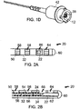
- FIG. 1D is a perspective view of a fiber connector assembly of the rotation catheter.
- the rotary part 10 is inserted inside the stationary part 40, as mentioned above.
- the rotary connector housing 38 is inside the stationary connector housing 42.
- the rotary connector housing 38 is attached to the fiber connector 12 and they rotate together. There is a small gap between the rotary connector housing 38 and the stationary connector housing 42.
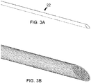
- FIG. 2A is a schematic elevational view of a fiber probe as a component of the rotation catheter according to an example of the invention.
- FIG. 2B is a partial cross-sectional view of the fiber probe of FIG. 2A .
- the fiber probe 20 is disposed at the optical tip 18 of the rotary part 10.
- the GRIN lens 24 is used to focus a light beam emitted by an optical fiber 50 extending from the fiber connector 12, with the help of a beam expander 54 between the terminal end of the optical fiber 50 and the GRIN lens 24, to achieve a substantial focal length toward the micro-mirror 22.
- the GRIN lens 24 has a refractive index that varies with a radial distance from an axis of the GRIN lens 24, decreasing radially outwardly, and has a diameter which is not smaller than an outer diameter of the beam expander 54.
- the GRIN lens 24 has a core surrounded by a glass cladding or air, and the core has a refractive index that varies with a radial distance from an axis of the GRIN lens 24, decreasing radially outwardly toward the cladding.
- the core of the GRIN lens 24 has a diameter which is not smaller than an outer diameter of the beam expander 54.
- the beam expander 54 has a first end coupled to the distal end of the optical fiber 50 and has a second end, and it permits a light beam emitting from a fiber core of the optical fiber 50 to pass from the first end to the second end and to expand from the first end to a larger beam size at the second end.
- the beam expander 54 comprises a no core fiber or a step-index multimode fiber (SI-MMF).
- SI-MMF step-index multimode fiber
- the micro-mirror 22 has a 35°-45° inclined surface to reflect the light from the GRIN lens 24 in the longitudinal direction to a lateral or radial direction outwardly from the longitudinal axis of the rotary part 10.
- the rotation of the rotary part 10 rotates the reflected light beam in the circumferential direction.
- the optical tip 18 preferably has a rounded distal end 60 to reduce rotary friction. Additional details of making and configuring the fiber probe 20 are described below.
- the optical fiber 50 is attached to the distal end portion of the torque coil 16 by adhesive 56, laser welding, or the like.
- One or more openings or windows 58 are used to apply the adhesive 56.
- the components of the fiber probe 20 are attached to the stainless steel tubing 32 by adhesive 62 or the like.
- One or more openings or windows 64 are used to apply the adhesive 62.
- One optical window 66 is provided for emitting the light beam reflected by the micro-mirror 22.
- the rotary tubing 32 has a length of about 5 mm in a specific example and may be made of some other metal or material that is sufficiently strong to support the components of the fiber probe 20.
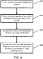
- FIG. 3A is an elevational view of an angled micro-mirror as a component of the fiber probe of FIG. 2A .
- the micro-mirror 22 is a light reflecting member which can be made of a variety of materials such as a metallic material, a fiber material, or a glass material. In one preferred embodiment, the material is stainless steel.
- the inclined light reflecting surface is polished and coated with a light reflecting film, which is preferably highly reflective. Examples include aluminum, silver, and gold. Possible alternative reflective coatings include dielectric coatings such as magnesium fluoride, calcium fluoride, aluminum oxide, silicon dioxide, and titanium dioxide.
- the micro-mirror 22 typically has an average length of about 0.5-1 mm and a diameter of about 0.1-0.2 mm.
- the average length is the length along the longitudinal axis; the actual length varies in the radial direction from the longitudinal axis because the light reflecting surface is inclined.
- the longitudinal dimension of the micro-mirror 22 is substantially larger than the lateral dimension (e.g., a ratio of about 2.5-10).
- FIG. 3B is an elevational view of a bundle of micro-mirrors which are polished and coated with a high reflectivity film in a manufacturing process according to an embodiment of the invention. Due to the small size of a micro-mirror 22 (less than about 0.25 mm in diameter and typically about 0.1-0.2 mm in diameter) and the small lateral dimension with respect to the longitudinal dimension, it is difficult to manufacture an individual micro-mirror by polishing and coating.
- the solution according to an aspect of this invention is to manufacture a plurality of micro-mirrors in a bundle that provides a larger effective lateral dimension. It is critical that a bundle has at least five longitudinal or cylindrical members to be polished and coated.
- the bundle preferably has tens of longitudinal members and more preferably has over 100 longitudinal members.
- the longitudinal members are typically about 25 mm in length and are cut to an average length of about 0.5-1 mm at the processed bundle end after the polishing and coating at the bundle end are completed.
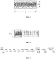
- FIG. 4 is an example of a flow diagram illustrating a process of manufacturing micro-mirrors according to an example of the invention.
- a bundle of at least five longitudinal members is formed.
- the longitudinal members having surfaces exposed at an end of the bundle.
- longitudinal members include stainless steel wires, glass rods, and polyimide fibers.
- the longitudinal members can be wrapped using a heat shrink tubing or the like.
- the longitudinal members may be temporarily glued or otherwise affixed together to prevent relative movement to ensure effective polishing and coating to produce proper angled reflective surfaces on the micro-mirrors.
- Step 404 polishes collectively the exposed surfaces of the longitudinal members at the end of the bundle.
- the polishing is done at an angle to the longitudinal axis of the bundle to create a common angled surface on each of the longitudinal members.
- the polishing may be performed with solid sand papers and/or liquid polish.
- the polishing is done initially with solid sand papers of different sizes ranging from about 40 ⁇ m to about 1 ⁇ m, followed by liquid polish with particle size of about 0.1 ⁇ m or smaller.
- the polished surfaces of the longitudinal members are coated with a light reflecting film.
- the bundle is separated and cut to the desired length at the polished and coated end to provide each cut longitudinal member as a light reflecting member having the coated surface as a light reflecting surface.
- the inventors have utilize the method using a bundle of 130 stainless steel wires to make micro-mirrors by polishing and coating.
- the diameter of a micro-mirror is about 0.1-0.2 mm and the average length is about 0.5-1 mm.
- the bundle diameter is about 3-4 mm for a bundle of 130 longitudinal members.
- the number of longitudinal members per bundle can be increased to a few hundreds or thousands.
- the overall bundle size is about 25 mm in diameter. This technique is effective and dramatically reduces the cost of making the micro-mirrors.
- the reflectivity of the silver-coated micro-mirrors is about 96% at 1310 nm wavelength band for the bundle of 130 micro-mirrors, corresponding to 0.35 dB loss for a round-trip. This reflectivity can be improved to about 98-99% with gold coating.
- the manufacturing cost per micro-mirror is substantially lower than conventional methods. The manufacturing process is commercially viable due to the low cost.
- the silver-coated stainless steel micro-mirrors are used to fabricate OCT rotary probes to achieve very good imaging with improved spatial resolution because the optical aberration, especially the cylinder lens effect, has been minimized.
- the fiber GRIN lens 24 and the micro-mirror 22 are sufficiently small in size so that they can be assembled within the rotary tubing 32.
- the OCT rotation catheter does not require the use of flush or lubricant, so that no dust comes out into the blood stream of the patient, thereby ensuring safety.
- the rotary probe 20 may be re-useable since it is isolated from the blood stream of the patient.
- Another feature of the rotary probe 20 is that the GRIN lens 24 and beam expander 54 are configured with the optical fiber 50 to produce a long focal length, as described below.
- FIG. 5 illustrates an optical schematic of light rays propagation along a GRIN fiber, showing periodical beam focusing.
- a , n 1, grin and n 2, grin are the radius of the fiber, and indexes of core and cladding, respectively.
- 0 ⁇ ⁇ ⁇ a represents the radius of light trace.
- Eq. (7) agrees with the value given by Eq. (3).
- the focal length of GRIN lenses without the beam expander is obtained as f ⁇ 1 ⁇ 1 e 2 2 1 2.44 ⁇ NA n 0 2 ⁇ D grin + D core 2
- FIG. 7 is a table showing experimental results of the focal length for a GRIN fiber spliced onto a single mode fiber and the focal length for a fiber GRIN lens having a beam expander spliced between the GRIN fiber and a single mode fiber.
- the maximum beam diameter is about 40 ⁇ m when a single mode fiber is spliced onto a fiber GRIN lens.
- the focal length is obtained from Eq. (9) as 0.38 mm, which explains why the longest focal length is always around 0.35 mm in experiments.
- the focal length is slightly longer for a single mode fiber with slightly larger NA, which agrees with Eq. (9).
- the effective way is to expand the beam diameter by splicing a short piece of beam expander (e.g., NCF or SI-MMF) between the single mode fiber and the GRIN fiber as a free space.
- a short piece of beam expander e.g., NCF or SI-MMF
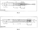
- FIG. 8 is a schematic illustration of an example of a fiberoptic device in which the dimensions of a no core fiber and a GRIN lens that are placed at the end of an optical fiber are selected to achieve a certain long focal length.
- FIG. 9 is a schematic illustration of another example of a fiberoptic device in which the dimensions of a no core fiber and a GRIN lens that are placed at the end of an optical fiber are selected to achieve a different long focal length. Note that while FIG. 9 shows a fiber GRIN lens having 0.1 mm core and 0.14 mm OD cladding, the fiber GRIN lens may have other configurations and dimensions including, for example, a 0.125 mm OD core and no cladding. In the configuration of FIG.
- the length of the no core fiber, L NCF is 0.65 mm and the length of the GRIN fiber is 0.17 mm. This produces the experimental result of a long focal length equal to 1.76 mm.
- the length of the no core fiber is 0.3 mm instead of 0.65 mm, while the length of the GRIN fiber is 0.26 mm instead of 0.17 mm.
- the measured focal length for the configuration of FIG. 8 is 0.62 mm, which is smaller than the focal length of 1.76 mm for the configuration of FIG. 9 because the beam diameter is smaller for the shorter no core fiber in FIG. 8 .
Landscapes
- Health & Medical Sciences (AREA)
- Life Sciences & Earth Sciences (AREA)
- Physics & Mathematics (AREA)
- Surgery (AREA)
- Engineering & Computer Science (AREA)
- Animal Behavior & Ethology (AREA)
- Biomedical Technology (AREA)
- Heart & Thoracic Surgery (AREA)
- Medical Informatics (AREA)
- Molecular Biology (AREA)
- Biophysics (AREA)
- Pathology (AREA)
- General Health & Medical Sciences (AREA)
- Public Health (AREA)
- Veterinary Medicine (AREA)
- Optics & Photonics (AREA)
- Nuclear Medicine, Radiotherapy & Molecular Imaging (AREA)
- Radiology & Medical Imaging (AREA)
- Investigating Or Analysing Materials By Optical Means (AREA)
- Endoscopes (AREA)
Description
- The present invention relates generally to scanning imaging devices and, more specifically, to a high spatial resolution rotation catheter for use in optical coherence tomography or the like.
- When light reflected from samples interferes with a reference beam, the frequencies of the interfering signals reveal the depth where the light is reflected. This technique has been used in imaging, known as Optical Coherence Tomography (OCT). OCT is an optical signal acquisition and processing method allowing extremely high-quality, micrometer-resolution, three-dimensional images from within optical scattering media (e.g., biological tissue) to be obtained. Scanning imaging probes are used in OCT and other interferometric imaging and ranging systems, as well as for delivery of other imaging modalities or therapeutic optical sources. See, e.g.,
U.S. Patent No. 6,891,984 . ApplicationUS 2004/066805 discloses a method of producing multiple reflective elements from a silica substrate, as well as coating and polishing. It fails to disclose forming a bundle of separated elements. - Document "Fabrication of Integrated Vertical Mirror Surfaces and Transparent Window for Packaging MEMS Devices", to Rahul Agarwal, et al. (2007), similarly also discloses producing multiple reflective elements, with steps of coating and polishing, while failing to disclose formind a bundle of elements.
-
- Typical fiber rotation probes for OCT imaging include fiber GRIN (Gradient-Index) lenses and micro-prisms. The disadvantage of using a micro-prism is that the emitting surface is curved. This curved surface acts as a cylinder lens that degrades the laser beam quality. The focal spot is in an elliptical shape rather than a circular shape. Polishing the curved surface of the fiber into a flat surface would solve this problem, but the mechanical processing could be very difficult. The high cost of the mechanical processing is another issue, since the fiber size micro-prisms (e.g., about 0.125 mm in diameter) that are attached to the fiber GRIN lenses are not suitable for mass production. The polished micro-prisms also require a clear tubing to form a kind of air bag to protect the polished surface in order to achieve a full internal reflection. Another disadvantage is the need for a fluid occupying the space between the prism and the inner sheath of the catheter in order to balance optical aberrations due to cylindrical lens effect. See, e.g.,
U.S. Patent Application Publication No. 2011/0137124 . As such, the distal end of the stationary part of the catheter must be open, making it vulnerable to dust contamination. - Alternatively, fiber rotation probes for OCT imaging using fiber GRIN lenses and micro-mirrors are also a popular design. One benefit of using a micro-mirror instead of a micro-prism is that there is no cylinder lens effect. The high cost of processing remains an issue, however, since the small size micro-mirrors are not commercially available and the processing cost for polishing and coating each micro-mirror to provide a highly reflective surface is very high. Currently, micro-mirrors are about 0.5 mm in diameter. Heretofore, micro-mirrors having a diameter of at most about 0.25 mm have not been made successfully.
- Examples of the present disclosure provide apparatuses and methods for a high spatial resolution rotation catheter for use in optical coherence tomography or the like. The rotation catheter has a rotary part which rotates with respect to a stationary part. At the distal end of the rotary part is an optical tip where a fiber probe is disposed. The fiber probe includes an angled micro-mirror spaced from a GRIN lens. The micro-mirror has an inclined surface at an angle of typically about 35°-45° to reflect the light from the GRIN lens in the longitudinal direction to a lateral or radial direction outwardly from the longitudinal axis of the rotary part. The rotation of the rotary part rotates the reflected light beam in the circumferential direction. The use of the micro-mirror minimizes optical aberration (no aberration theoretically). As a result, no fluid is required to balance optical aberrations and thus the distal end of the stationary part can be sealed to prevent blood from blocking the optical window of the fiber probe and prevent any dust from contaminating the blood. Furthermore, the invention employs a process to manufacture a plurality of micro-mirrors in a bundle that provides a larger effective lateral dimension. The bundle has at least five longitudinal members to be polished and coated. The bundle preferably has tens of longitudinal members and more preferably has over 100 longitudinal members. This manufacturing process makes it possible to make a micro-mirror having a diameter of at most about 0.25 mm and an inclined light reflecting surface at a constant angle with high reflectivity.
- In accordance with an aspect of the present invention, an optical coherence tomography (OCT) rotation catheter comprises: a catheter body; a tubular member disposed in the catheter body, the tubular member having a hollow interior extending between a proximal end and a distal end, a longitudinal axis extending in a longitudinal direction between the distal end and the proximal end, the tubular member being rotatable around the longitudinal axis; an optical fiber extending along the hollow interior of the tubular member and having an optical fiber distal end at a location near the distal end of the tubular member to direct light through the optical fiber distal end toward the distal end of the tubular member; and a light reflecting member which is disposed in the hollow interior of the tubular member and distal of the optical fiber distal end and which is configured to rotate around the longitudinal axis with the tubular member, the light reflecting member including a light reflecting surface which is spaced from and faces the optical fiber distal end and which is inclined to reflect the light from the optical fiber in a radial direction at an angle with respect to the longitudinal axis, the reflected light rotating in a circumferential direction due to rotation of the light reflecting member around the longitudinal axis. The light reflecting member has a diameter of at most about 0.25 mm, and the light reflecting surface is polished and coated with a light reflecting film.
- In some examples, the light reflecting member is made of a material selected from the group consisting of metallic materials, fiber materials, and glass materials. In one preferred embodiment, the material is stainless steel. The light reflecting film comprises a material selected from the group consisting of aluminum, silver, gold, and dielectric coating materials. The light reflecting member and the optical fiber distal end are attached to the tubular member to rotate with the tubular member around the longitudinal axis; and the tubular member is rotatable with respect to the catheter body, the catheter body has a distal end which is distal of the distal end of the tubular member, and the distal end of the catheter body is sealed. The tubular member and the catheter are optically transparent at least in a region near the light reflecting member to allow the reflected light from the light reflecting surface to pass therethrough.
- In specific examples, the OCT rotation catheter further includes a beam expander having a first end coupled to the distal end of the optical fiber and having a second end, the beam expander permitting a light beam emitting from a fiber core of the optical fiber to pass from the first end to the second end and to expand from the first end to a larger beam size at the second end. A gradient-index fiber lens is coupled to the second end of the beam expander to receive the light beam from the beam expander and focus the light beam. The gradient-index fiber lens is proximal of the light reflecting member and spaced from the light reflecting surface. The optical fiber is a single mode fiber, and the beam expander comprises a no core fiber or a step-index multimode fiber. The gradient-index fiber lens has a core surrounded by a glass cladding or air, the core having a refractive index that varies with a radial distance from an axis of the gradient-index fiber lens, decreasing radially outwardly toward the cladding, and the core of the gradient-index fiber lens has a diameter which is not smaller than an outer diameter of the beam expander. The gradient-index fiber lens has a refractive index that varies with a radial distance from an axis of the gradient-index fiber lens, decreasing radially outwardly, and the gradient-index fiber lens has a diameter which is not smaller than an outer diameter of the beam expander.
- In some examples, the stationary shaft tubular member is optically transparent at least in a region near the light reflecting member to allow the reflected light from the light reflecting surface to pass therethrough. The tubular member is rotatable with respect to the catheter body, and a clearance of less than about 0.25 mm is provided between the outer surface of the tubular member and the inner surface of the catheter body.
- Another aspect of the invention is directed to a method of forming an optical coherence tomography (OCT) rotation catheter. The method comprises: placing a tubular member in a catheter body, the tubular member having a hollow interior extending between a proximal end and a distal end, a longitudinal axis extending in a longitudinal direction between the distal end and the proximal end, the tubular member being rotatable around the longitudinal axis; providing an optical fiber extending along the hollow interior of the tubular member and having an optical fiber distal end at a location near the distal end of the tubular member to direct light through the optical fiber distal end toward the distal end of the tubular member; forming a light reflecting member which has a diameter of at most about 0.25 mm; and positioning the light reflecting member in the hollow interior of the tubular member and distal of the optical fiber distal end and which is configured to rotate around the longitudinal axis with the tubular member, the light reflecting member including a light reflecting surface which is spaced from and faces the optical fiber distal end and which is inclined to reflect the light from the optical fiber in a radial direction at an angle with respect to the longitudinal axis, the reflected light rotating in a circumferential direction due to rotation of the light reflecting member around the longitudinal axis. Forming the light reflecting member comprises forming a bundle of at least five longitudinal members having surfaces exposed at an end of the bundle, the longitudinal members; polishing collectively the exposed surfaces of the longitudinal members at the end of the bundle; coating the polished surfaces of the longitudinal members with a light reflecting film; and separating the bundle to provide each longitudinal member as a light reflecting member having the coated surface as a light reflecting surface.
- In some examples, the method further comprises attaching the light reflecting member and the optical fiber distal end to the tubular member to rotate with the tubular member around the longitudinal axis with respect to the catheter body, and sealing a distal end of the catheter body which is distal of the distal end of the tubular member.
- Another aspect of this invention is directed to a method of providing a light reflecting member having a light reflecting surface. The method comprises: forming a bundle of at least five longitudinal members having surfaces exposed at an end of the bundle, the longitudinal members; polishing collectively the exposed surfaces of the longitudinal members at the end of the bundle; coating the polished surfaces of the longitudinal members with a light reflecting film; and separating the bundle to provide each longitudinal member as a light reflecting member having the coated surface as a light reflecting surface.
- In some embodiments, the longitudinal members each have a diameter of at most about 0.25 mm. The bundle has at least 100 longitudinal members.
- These and other features and advantages of the present invention will become apparent to those of ordinary skill in the art in view of the following detailed description of the specific examples.
-
-
FIG. 1A is a schematic view of the rotary part of a rotation catheter according to an example of the present invention. -
FIG. 1B is another schematic view of the rotary part of the rotation catheter ofFIG. 1A . -
FIG. 1C is a schematic view of a stationary part of the rotation catheter according to an example of the present invention. -
FIG. 1D is a perspective view of a fiber connector assembly of the rotation catheter. -
FIG. 2A is a schematic elevational view of a fiber probe as a component of the rotation catheter according to an example of the invention. -
FIG. 2B is a partial cross-sectional view of the fiber probe ofFIG. 2A . -
FIG. 3A is an elevational view of an angled micro-mirror as a component of the fiber probe ofFIG. 2A . -
FIG. 3B is an elevational view of a bundle of micro-mirrors which are polished and coated with a high reflectivity film in a manufacturing process according to an embodiment of the invention. -
FIG. 4 is an example of a flow diagram illustrating a process of manufacturing micro-mirrors according to an example of the invention. -
FIG. 5 illustrates an optical schematic of light rays propagation along a GRIN fiber, showing periodical beam focusing. -
FIG. 6 illustrates an optical schematic of light rays propagating along a GRIN fiber, showing that a quarter period length could collimate a beam into a parallel beam if the diffraction could be ignored. -
FIG. 7 is a table showing experimental results of the focal length for a GRIN fiber spliced onto a single mode fiber and the focal length for a fiber GRIN lens having a no core fiber as a beam expander spliced between the GRIN fiber and a single mode fiber. -
FIG. 8 is a schematic illustration of an example of a fiberoptic device in which the dimensions of a no core fiber as a beam expander and a GRIN lens that are placed at the end of an optical fiber are selected to achieve a certain long focal length. -
FIG. 9 is a schematic illustration of another example of a fiberoptic device in which the dimensions of a no core fiber as beam expander and a GRIN lens that are placed at the end of an optical fiber are selected to achieve a different long focal length. - In the following detailed description of the invention, reference is made to the accompanying drawings which form a part of the disclosure, and in which are shown by way of illustration, examples by which the invention may be practiced. The invention is defined in the claims.
- In the following description, relative orientation and placement terminology, such as the terms horizontal, vertical, left, right, top and bottom, is used. It will be appreciated that these terms refer to relative directions and placement in a two dimensional layout with respect to a given orientation of the layout. For a different orientation of the layout, different relative orientation and placement terms may be used to describe the same objects or operations.
- Examples, as will be described in greater detail below, provide apparatuses and methods for a high spatial resolution rotation catheter for use in optical coherence tomography or the like.
-
FIG. 1A is a schematic view of the rotary part of a rotation catheter according to an example of the present invention. Therotary part 10 has a proximal end coupled to afiber connector 12. The proximal portion of therotary part 10 is atubing 14 that is preferably made of straight and flexible material such as Nitinol or the like. The distal portion of therotary part 10 is atorque coil 16. Theproximal tubing 14 may be glued, laser welded, or otherwise affixed to thefiber connector 12 and thetorque coil 16. At the distal end of therotary part 10 is anoptical tip 18 where afiber probe 20 is disposed. Thefiber probe 20 includes anangled micro-mirror 22 spaced from aGRIN lens 24. As described in greater detail below, theGRIN lens 24 is used to focus a light beam emitted by an optical fiber extending from thefiber connector 12, with the help of a beam expander between the terminal end of the optical fiber and theGRIN lens 24, to achieve a substantially longer focal length than that of a GRIN lens alone (e.g., a focal length of about 1.8-2.0 mm). The micro-mirror 22 has an inclined surface at an angle of typically about 35°-45° to reflect the light from theGRIN lens 24 in the longitudinal direction to a lateral or radial direction outwardly from the longitudinal axis of therotary part 10. The rotation of therotary part 10 rotates the reflected light beam in the circumferential direction. In the specific example shown inFIG. 1A , theoptical tip 18 has a stainlesssteel rotary tubing 32 with aclear tubing portion 34 to provide an optical window that is optically transparent and allows the light beam reflected from the micro-mirror 22 to pass therethrough to a target tissue and back to single mode fiber via the micro-mirror 22. -
FIG. 1B is another schematic view of therotary part 10 of the rotation catheter ofFIG. 1A . Thefiber connector 12 is mounted into arotary connector housing 38. Therotary housing 38 is a component of therotary part 10 that rotates around the longitudinal axis. -
FIG. 1C is a schematic view of a stationary part of the rotation catheter according to an example of the present invention. Thestationary shaft 40 includes astationary connector housing 42, a large diameter proximal tubing 44, and a longdistal tubing 46. Thedistal tubing 46 is preferably optically transparent to allow light to pass therethrough, and may be made of FEP (fluorinated ethylene propylene) or the like. Therotary part 10 is mounted inside thestationary part 40, with therotary connector housing 38 inside thestationary connector housing 42, the rotary partproximal tubing 14 inside the stationary part proximal tubing 44, and thetorque coil 16 inside the transparentdistal tubing 46. Generally, small clearance (e.g., less than about 0.25 mm) is provided between the corresponding components of therotary part 10 and thestationary part 40 to allow therotary part 10 to rotate around the longitudinal axis with respect to thestationary part 40. Adistal end 48 of thestationary part 40 is located near and is distal of theoptical tip 18 of therotary part 10, and is preferably sealed to prevent blood from blocking the optical window of theclear tubing portion 34 and prevent any dust from contaminating the blood. There is about 25 mm clearance or less between the sealeddistal end 48 of thestationary part 40 and thedistal tip 18 of therotary part 10. -
FIG. 1D is a perspective view of a fiber connector assembly of the rotation catheter. Therotary part 10 is inserted inside thestationary part 40, as mentioned above. Therotary connector housing 38 is inside thestationary connector housing 42. Therotary connector housing 38 is attached to thefiber connector 12 and they rotate together. There is a small gap between therotary connector housing 38 and thestationary connector housing 42. -
FIG. 2A is a schematic elevational view of a fiber probe as a component of the rotation catheter according to an example of the invention.FIG. 2B is a partial cross-sectional view of the fiber probe ofFIG. 2A . As discussed above in connection withFIG. 1A , thefiber probe 20 is disposed at theoptical tip 18 of therotary part 10. TheGRIN lens 24 is used to focus a light beam emitted by anoptical fiber 50 extending from thefiber connector 12, with the help of abeam expander 54 between the terminal end of theoptical fiber 50 and theGRIN lens 24, to achieve a substantial focal length toward the micro-mirror 22. In general, theGRIN lens 24 has a refractive index that varies with a radial distance from an axis of theGRIN lens 24, decreasing radially outwardly, and has a diameter which is not smaller than an outer diameter of thebeam expander 54. In the example shown, theGRIN lens 24 has a core surrounded by a glass cladding or air, and the core has a refractive index that varies with a radial distance from an axis of theGRIN lens 24, decreasing radially outwardly toward the cladding. The core of theGRIN lens 24 has a diameter which is not smaller than an outer diameter of thebeam expander 54. Thebeam expander 54 has a first end coupled to the distal end of theoptical fiber 50 and has a second end, and it permits a light beam emitting from a fiber core of theoptical fiber 50 to pass from the first end to the second end and to expand from the first end to a larger beam size at the second end. In specific examples, thebeam expander 54 comprises a no core fiber or a step-index multimode fiber (SI-MMF). InFIG. 2B , the micro-mirror 22 has a 35°-45° inclined surface to reflect the light from theGRIN lens 24 in the longitudinal direction to a lateral or radial direction outwardly from the longitudinal axis of therotary part 10. The rotation of therotary part 10 rotates the reflected light beam in the circumferential direction. Theoptical tip 18 preferably has a roundeddistal end 60 to reduce rotary friction. Additional details of making and configuring thefiber probe 20 are described below. - The
optical fiber 50 is attached to the distal end portion of thetorque coil 16 by adhesive 56, laser welding, or the like. One or more openings orwindows 58 are used to apply the adhesive 56. The components of the fiber probe 20 (micro-mirror 22 and GRIN lens 24) are attached to thestainless steel tubing 32 by adhesive 62 or the like. One or more openings orwindows 64 are used to apply the adhesive 62. Oneoptical window 66 is provided for emitting the light beam reflected by the micro-mirror 22. Therotary tubing 32 has a length of about 5 mm in a specific example and may be made of some other metal or material that is sufficiently strong to support the components of thefiber probe 20. To provide theclear tubing portion 34 to allow the light beam reflected from the micro-mirror 22 to pass therethrough, one way is to use a piece of thin clear heat shrink tubing over all openings orwindows -
FIG. 3A is an elevational view of an angled micro-mirror as a component of the fiber probe ofFIG. 2A . The micro-mirror 22 is a light reflecting member which can be made of a variety of materials such as a metallic material, a fiber material, or a glass material. In one preferred embodiment, the material is stainless steel. The inclined light reflecting surface is polished and coated with a light reflecting film, which is preferably highly reflective. Examples include aluminum, silver, and gold. Possible alternative reflective coatings include dielectric coatings such as magnesium fluoride, calcium fluoride, aluminum oxide, silicon dioxide, and titanium dioxide. The micro-mirror 22 typically has an average length of about 0.5-1 mm and a diameter of about 0.1-0.2 mm. The average length is the length along the longitudinal axis; the actual length varies in the radial direction from the longitudinal axis because the light reflecting surface is inclined. The longitudinal dimension of the micro-mirror 22 is substantially larger than the lateral dimension (e.g., a ratio of about 2.5-10). -
FIG. 3B is an elevational view of a bundle of micro-mirrors which are polished and coated with a high reflectivity film in a manufacturing process according to an embodiment of the invention. Due to the small size of a micro-mirror 22 (less than about 0.25 mm in diameter and typically about 0.1-0.2 mm in diameter) and the small lateral dimension with respect to the longitudinal dimension, it is difficult to manufacture an individual micro-mirror by polishing and coating. The solution according to an aspect of this invention is to manufacture a plurality of micro-mirrors in a bundle that provides a larger effective lateral dimension. It is critical that a bundle has at least five longitudinal or cylindrical members to be polished and coated. The bundle preferably has tens of longitudinal members and more preferably has over 100 longitudinal members. The longitudinal members are typically about 25 mm in length and are cut to an average length of about 0.5-1 mm at the processed bundle end after the polishing and coating at the bundle end are completed. -
FIG. 4 is an example of a flow diagram illustrating a process of manufacturing micro-mirrors according to an example of the invention. Instep 402, a bundle of at least five longitudinal members is formed. The longitudinal members having surfaces exposed at an end of the bundle. Examples of longitudinal members include stainless steel wires, glass rods, and polyimide fibers. To form the bundle, the longitudinal members can be wrapped using a heat shrink tubing or the like. In addition, the longitudinal members may be temporarily glued or otherwise affixed together to prevent relative movement to ensure effective polishing and coating to produce proper angled reflective surfaces on the micro-mirrors. Step 404 polishes collectively the exposed surfaces of the longitudinal members at the end of the bundle. The polishing is done at an angle to the longitudinal axis of the bundle to create a common angled surface on each of the longitudinal members. The polishing may be performed with solid sand papers and/or liquid polish. In specific examples, the polishing is done initially with solid sand papers of different sizes ranging from about 40 µm to about 1 µm, followed by liquid polish with particle size of about 0.1 µm or smaller. Instep 406, the polished surfaces of the longitudinal members are coated with a light reflecting film. Instep 408, the bundle is separated and cut to the desired length at the polished and coated end to provide each cut longitudinal member as a light reflecting member having the coated surface as a light reflecting surface. - The inventors have utilize the method using a bundle of 130 stainless steel wires to make micro-mirrors by polishing and coating. The diameter of a micro-mirror is about 0.1-0.2 mm and the average length is about 0.5-1 mm. The bundle diameter is about 3-4 mm for a bundle of 130 longitudinal members. The number of longitudinal members per bundle can be increased to a few hundreds or thousands. For a bundle of 10,000 wires, the overall bundle size is about 25 mm in diameter. This technique is effective and dramatically reduces the cost of making the micro-mirrors. The reflectivity of the silver-coated micro-mirrors is about 96% at 1310 nm wavelength band for the bundle of 130 micro-mirrors, corresponding to 0.35 dB loss for a round-trip. This reflectivity can be improved to about 98-99% with gold coating. The manufacturing cost per micro-mirror is substantially lower than conventional methods. The manufacturing process is commercially viable due to the low cost. The silver-coated stainless steel micro-mirrors are used to fabricate OCT rotary probes to achieve very good imaging with improved spatial resolution because the optical aberration, especially the cylinder lens effect, has been minimized.
- In assembling the
OCT rotary probe 20 for the OCT rotation catheter, thefiber GRIN lens 24 and the micro-mirror 22 are sufficiently small in size so that they can be assembled within therotary tubing 32. The OCT rotation catheter does not require the use of flush or lubricant, so that no dust comes out into the blood stream of the patient, thereby ensuring safety. Therotary probe 20 may be re-useable since it is isolated from the blood stream of the patient. Another feature of therotary probe 20 is that theGRIN lens 24 andbeam expander 54 are configured with theoptical fiber 50 to produce a long focal length, as described below. -
FIG. 5 illustrates an optical schematic of light rays propagation along a GRIN fiber, showing periodical beam focusing.FIG. 6 illustrates an optical schematic of light rays propagating along a GRIN fiber, showing that a quarter or three quarters period length can collimate a beam into a parallel beam if the diffraction can be ignored. If the incident beam is a point size, the
- The index profile of a GRIN fiber is usually expressed as

where a, n 1,grin and n 2,grin are the radius of the fiber, and indexes of core and cladding, respectively. 0 ≤ ρ ≤ a represents the radius of light trace. The parameter Δ is expressed as
where NAgrin is the numerical aperture of the GRIN fiber. When a light is incident into the core of the GRIN fiber at an angle of θ 0, this light will turn its direction (θ = 0) at the maximum radius and light equation is expressed as
- In general, the radius of the light incident at an angle of θ with respect to the axial position (z) can be expressed as

where, - θ 0 ≤ θ ≤ θ 0 describes the range of the incident angle. Clearly, Eq. (4) shows that the GRIN fiber can periodically focus the incident beam. The period is expressed as
- Since the period is related to the incident angle, the self focusing effect will wash out by averaging (- θ 0 ≤ θ ≤ θ 0) when the length of GRIN fiber is longer than L max as

- For typical parameters of DGRIN = 100 µm, θ 0=8°, NAgrin = 0.29, n 1,grin =1.47, Eq. (6) gives L max ∼ 160 mm. Considering a Gaussian profile power distribution with respect to the incident angle, the real maximum length is slightly longer than this value.
- When


- Eq. (7) agrees with the value given by Eq. (3). Considering the fiber diameter Dcore , and utilizing reflection equations for a light beam emitting from the fiber core of a single mode fiber, which is a step-index single mode fiber, in conjunction with Eq. (7), the maximum diameter D max = 2ρ max+Dcore is then obtained as

where Dgrin is the GRIN fiber core diameter. Utilizing the reflection equations for a light beam emitting from the fiber core of a single mode fiber in conjunction with Eq. (8), the focal length of GRIN lenses without the beam expander is obtained as
-
FIG. 7 is a table showing experimental results of the focal length for a GRIN fiber spliced onto a single mode fiber and the focal length for a fiber GRIN lens having a beam expander spliced between the GRIN fiber and a single mode fiber. For the fibers with parameters of NA = 0.09, NAgrin = 0.29, n 1,grin =1.487, Dgrin = 100µm, the maximum beam diameter is about 40 µm when a single mode fiber is spliced onto a fiber GRIN lens. The focal length is obtained from Eq. (9) as 0.38 mm, which explains why the longest focal length is always around 0.35 mm in experiments. Experiments also show that the focal length is slightly longer for a single mode fiber with slightly larger NA, which agrees with Eq. (9). In order to obtain a long focal length, the effective way is to expand the beam diameter by splicing a short piece of beam expander (e.g., NCF or SI-MMF) between the single mode fiber and the GRIN fiber as a free space. -
FIG. 8 is a schematic illustration of an example of a fiberoptic device in which the dimensions of a no core fiber and a GRIN lens that are placed at the end of an optical fiber are selected to achieve a certain long focal length.FIG. 9 is a schematic illustration of another example of a fiberoptic device in which the dimensions of a no core fiber and a GRIN lens that are placed at the end of an optical fiber are selected to achieve a different long focal length. Note that whileFIG. 9 shows a fiber GRIN lens having 0.1 mm core and 0.14 mm OD cladding, the fiber GRIN lens may have other configurations and dimensions including, for example, a 0.125 mm OD core and no cladding. In the configuration ofFIG. 9 , the length of the no core fiber, LNCF, is 0.65 mm and the length of the GRIN fiber is 0.17 mm. This produces the experimental result of a long focal length equal to 1.76 mm. In the configuration ofFIG. 8 , the length of the no core fiber is 0.3 mm instead of 0.65 mm, while the length of the GRIN fiber is 0.26 mm instead of 0.17 mm. The measured focal length for the configuration ofFIG. 8 is 0.62 mm, which is smaller than the focal length of 1.76 mm for the configuration ofFIG. 9 because the beam diameter is smaller for the shorter no core fiber inFIG. 8 . When the length of the no core fiber and the diameters of the GRIN fiber and the no core fiber are doubled, the theoretical focal length would be increased by four times, which could be a few millimeters long. For large dimension fibers, a special designed fusion splicer rather than the regular one may have to be used. Additional details of the SMF, NCF, and GRIN lens can be found inU.S. Patent Application No. 12/829,787, filed July 2, 2010
Claims (5)
- A method of providing a light reflecting member having a light reflecting surface, the method comprising:forming a bundle of at least five longitudinal members having surfaces exposed at an end of the bundle, the forming comprising affixing together the longitudinal members to prevent relative movement;polishing collectively the exposed surfaces of the longitudinal members at the end of the bundle;coating the polished surfaces of the longitudinal members with a light reflecting film; andseparating the bundle to provide each longitudinal member as a light reflecting member having the coated surface as a light reflecting surface;wherein the longitudinal members are made of metal, characterised in that:
the light reflecting film comprises a material selected from the group consisting of aluminum, silver, and gold. - The method of claim 1,
wherein the longitudinal members each have a diameter of at most about 0.25 mm. - The method of claim 1,
wherein the bundle has at least 100 longitudinal members. - The method of claim 1,
wherein the exposed surfaces of the longitudinal members at the end of the bundle are collectively polished at an angle to a longitudinal axis of the bundle and form inclined exposed surfaces. - The method of claim 1,
wherein the longitudinal members are made of stainless steel.
Applications Claiming Priority (2)
| Application Number | Priority Date | Filing Date | Title |
|---|---|---|---|
| US13/184,655 US9131850B2 (en) | 2011-07-18 | 2011-07-18 | High spatial resolution optical coherence tomography rotation catheter |
| PCT/US2012/047017 WO2013012841A1 (en) | 2011-07-18 | 2012-07-17 | High spatial resolution optical coherence tomography rotation catheter |
Publications (3)
| Publication Number | Publication Date |
|---|---|
| EP2734114A1 EP2734114A1 (en) | 2014-05-28 |
| EP2734114A4 EP2734114A4 (en) | 2015-05-06 |
| EP2734114B1 true EP2734114B1 (en) | 2018-05-16 |
Family
ID=47556233
Family Applications (1)
| Application Number | Title | Priority Date | Filing Date |
|---|---|---|---|
| EP12814783.2A Not-in-force EP2734114B1 (en) | 2011-07-18 | 2012-07-17 | High spatial resolution optical coherence tomography rotation catheter |
Country Status (4)
| Country | Link |
|---|---|
| US (1) | US9131850B2 (en) |
| EP (1) | EP2734114B1 (en) |
| JP (1) | JP6087352B2 (en) |
| WO (1) | WO2013012841A1 (en) |
Families Citing this family (17)
| Publication number | Priority date | Publication date | Assignee | Title |
|---|---|---|---|---|
| WO2014088885A1 (en) * | 2012-12-04 | 2014-06-12 | Ninepoint Medical, Inc. | Low cost extended depth of field optical probes |
| US20150025369A1 (en) * | 2013-07-17 | 2015-01-22 | Corning Incorporated | Housing for the oct probe, oct probe assembly, and a method of making such assembly |
| JP2015097569A (en) * | 2013-11-18 | 2015-05-28 | 住友電気工業株式会社 | Optical probe for optical interference tomographic imaging, and manufacturing method thereof |
| WO2015117241A1 (en) | 2014-02-05 | 2015-08-13 | British Columbia Cancer Agency Branch | Systems for optical imaging of biological tissues |
| EP3753502B1 (en) | 2014-02-06 | 2022-11-09 | Nipro Corporation | Catheter having cutter with torque shaft |
| JP6354324B2 (en) * | 2014-05-20 | 2018-07-11 | ニプロ株式会社 | catheter |
| CN107949311B (en) | 2015-04-16 | 2021-04-16 | Gentuity有限责任公司 | Low-light level probe for neurology |
| CN104825121B (en) * | 2015-05-08 | 2017-04-26 | 南京微创医学科技股份有限公司 | Endoscopic OCT (Optical Coherence Tomography) miniature probe, OCT imaging system and use method |
| WO2016182164A1 (en) * | 2015-05-12 | 2016-11-17 | 한국과학기술원 | Apparatus and method for high-speed scanning of coronary artery blood vessel |
| JP6981967B2 (en) | 2015-08-31 | 2021-12-17 | ジェンテュイティ・リミテッド・ライアビリティ・カンパニーGentuity, LLC | Imaging system including imaging probe and delivery device |
| US10022046B2 (en) * | 2015-09-02 | 2018-07-17 | Synaptive Medical (Barbados) Inc. | Multi-channel optical coherence tomography probe for use in a medical procedure |
| CN105615819A (en) * | 2016-01-13 | 2016-06-01 | 苏州佳像视讯科技有限公司 | Miniature endoscope camera device |
| WO2018009529A1 (en) | 2016-07-05 | 2018-01-11 | The General Hospital Corporation | Systems and methods for an actively controlled optical imaging device |
| US10041163B1 (en) | 2017-02-03 | 2018-08-07 | Ge-Hitachi Nuclear Energy Americas Llc | Plasma spray coating for sealing a defect area in a workpiece |
| CN107515446B (en) * | 2017-09-14 | 2024-04-26 | 浙江大学 | Method for expanding focal depth based on optical fiber type pupil filter and probe |
| US11684242B2 (en) | 2017-11-28 | 2023-06-27 | Gentuity, Llc | Imaging system |
| WO2021113375A1 (en) * | 2019-12-03 | 2021-06-10 | Boston Scientific Scimed, Inc. | Medical system comprising a medical imaging device with a light source and means to move a sensor based on the detection of light by the sensor |
Citations (1)
| Publication number | Priority date | Publication date | Assignee | Title |
|---|---|---|---|---|
| EP1731241A1 (en) * | 2005-06-06 | 2006-12-13 | Asahi Intecc Co., Ltd. | A heat mold device and a method of making a guide wire by using the same heat mold |
Family Cites Families (24)
| Publication number | Priority date | Publication date | Assignee | Title |
|---|---|---|---|---|
| US3414837A (en) * | 1963-12-18 | 1968-12-03 | American Optical Corp | Plural fiber optic laser construction |
| JPS5590257A (en) * | 1978-12-27 | 1980-07-08 | Casio Comput Co Ltd | Method of polishing end face of bar of very small diameter |
| JPS6029414Y2 (en) * | 1982-02-04 | 1985-09-05 | 富士通株式会社 | Optical fiber processing jig |
| US4710216A (en) * | 1982-04-19 | 1987-12-01 | Fuji Photo Optical Co., Ltd. | Method of making flexible optical fiber bundle |
| US4693035A (en) * | 1985-10-30 | 1987-09-15 | Buehler Ltd. | Multiple optical fiber polishing apparatus |
| US4859289A (en) * | 1986-05-26 | 1989-08-22 | Sumitomo Electric Industries, Ltd. | Process for producing a metal wire useful as rubber product reinforcement |
| JP3485329B2 (en) * | 1992-02-07 | 2004-01-13 | 株式会社町田製作所 | Laser light generator |
| US5421334A (en) * | 1993-10-06 | 1995-06-06 | Cardiovascular Imaging Systems, Inc. | Pre-filled imaging catheter |
| DE69633411T2 (en) * | 1995-10-13 | 2005-10-20 | Transvascular, Inc., Menlo Park | METHOD AND DEVICE FOR PREVENTING ARTERIAL ATTRACTIONS AND / OR FOR CARRYING OUT OTHER TRANSVASCULAR INTERVENTIONS |
| US5953477A (en) * | 1995-11-20 | 1999-09-14 | Visionex, Inc. | Method and apparatus for improved fiber optic light management |
| US5830145A (en) * | 1996-09-20 | 1998-11-03 | Cardiovascular Imaging Systems, Inc. | Enhanced accuracy of three-dimensional intraluminal ultrasound (ILUS) image reconstruction |
| US6615072B1 (en) * | 1999-02-04 | 2003-09-02 | Olympus Optical Co., Ltd. | Optical imaging device |
| US6393187B1 (en) * | 2000-08-03 | 2002-05-21 | Lucent Technologies | Optical fiber arrays with reduced return loss and methods for making same |
| US6542665B2 (en) * | 2001-02-17 | 2003-04-01 | Lucent Technologies Inc. | GRIN fiber lenses |
| US6891984B2 (en) * | 2002-07-25 | 2005-05-10 | Lightlab Imaging, Llc | Scanning miniature optical probes with optical distortion correction and rotational control |
| WO2004034523A2 (en) * | 2002-10-04 | 2004-04-22 | Spectra Systems Corporation | Monolithic, side-pumped, passively q-switched solid-state laser |
| US8983582B2 (en) | 2004-12-20 | 2015-03-17 | Advanced Cardiovascular Systems, Inc. | Methods and apparatuses for positioning within an internal channel |
| WO2006133030A2 (en) * | 2005-06-06 | 2006-12-14 | Board Of Regents | Oct using spectrally resolved bandwidth |
| JP5226528B2 (en) * | 2005-11-21 | 2013-07-03 | マイクロビジョン,インク. | Display having an image guiding substrate |
| US20080073592A1 (en) * | 2006-07-21 | 2008-03-27 | Panning Eric M | Reflective optical illumination collector |
| JP4461216B2 (en) * | 2007-03-02 | 2010-05-12 | 並木精密宝石株式会社 | Motor and endoscope probe equipped with the motor |
| WO2009009802A1 (en) * | 2007-07-12 | 2009-01-15 | Volcano Corporation | Oct-ivus catheter for concurrent luminal imaging |
| WO2009009799A1 (en) | 2007-07-12 | 2009-01-15 | Volcano Corporation | Catheter for in vivo imaging |
| US9125562B2 (en) | 2009-07-01 | 2015-09-08 | Avinger, Inc. | Catheter-based off-axis optical coherence tomography imaging system |
-
2011
- 2011-07-18 US US13/184,655 patent/US9131850B2/en active Active
-
2012
- 2012-07-17 EP EP12814783.2A patent/EP2734114B1/en not_active Not-in-force
- 2012-07-17 JP JP2014521702A patent/JP6087352B2/en not_active Expired - Fee Related
- 2012-07-17 WO PCT/US2012/047017 patent/WO2013012841A1/en active Application Filing
Patent Citations (1)
| Publication number | Priority date | Publication date | Assignee | Title |
|---|---|---|---|---|
| EP1731241A1 (en) * | 2005-06-06 | 2006-12-13 | Asahi Intecc Co., Ltd. | A heat mold device and a method of making a guide wire by using the same heat mold |
Non-Patent Citations (1)
| Title |
|---|
| RAHUL AGARWAL ET AL: "Fabrication of Integrated Vertical Mirror Surfaces and Transparent Window for Packaging MEMS Devices", JOURNAL OF MICROELECTROMECHANICAL SYSTEMS, IEEE SERVICE CENTER, US, vol. 16, no. 1, 1 February 2007 (2007-02-01), pages 122 - 129, XP011165330, ISSN: 1057-7157, DOI: 10.1109/JMEMS.2006.886010 * |
Also Published As
| Publication number | Publication date |
|---|---|
| US20130023760A1 (en) | 2013-01-24 |
| JP6087352B2 (en) | 2017-03-01 |
| WO2013012841A1 (en) | 2013-01-24 |
| EP2734114A4 (en) | 2015-05-06 |
| EP2734114A1 (en) | 2014-05-28 |
| US9131850B2 (en) | 2015-09-15 |
| JP2014520655A (en) | 2014-08-25 |
Similar Documents
| Publication | Publication Date | Title |
|---|---|---|
| EP2734114B1 (en) | High spatial resolution optical coherence tomography rotation catheter | |
| JP7202341B2 (en) | Optical coherence tomography system | |
| US20200116941A1 (en) | Grin lens and methods of making the same | |
| JP4997112B2 (en) | Apparatus for transmitting at least one electromagnetic radiation and method of manufacturing the same | |
| JP4659137B1 (en) | Side emission device and manufacturing method thereof | |
| EP2972535B1 (en) | Optical fiber beam directing systems and apparatuses | |
| US10426326B2 (en) | Fiber optic correction of astigmatism | |
| US10234676B1 (en) | Optical probes with reflecting components for astigmatism correction | |
| JP2002540465A (en) | Single mode fiber optic coupling system | |
| JP5187915B2 (en) | Method for manufacturing side emission device | |
| JP7116111B2 (en) | Optical probe and its assembly | |
| US20180177404A1 (en) | Gradient Index Lens Assembly-Based Imaging Apparatus, Systems and Methods | |
| EP2706388A1 (en) | Optical probe | |
| EP2963467B1 (en) | Lateral light emitting device | |
| WO2016167204A1 (en) | Optical probe |
Legal Events
| Date | Code | Title | Description |
|---|---|---|---|
| PUAI | Public reference made under article 153(3) epc to a published international application that has entered the european phase |
Free format text: ORIGINAL CODE: 0009012 |
|
| 17P | Request for examination filed |
Effective date: 20140210 |
|
| AK | Designated contracting states |
Kind code of ref document: A1 Designated state(s): AL AT BE BG CH CY CZ DE DK EE ES FI FR GB GR HR HU IE IS IT LI LT LU LV MC MK MT NL NO PL PT RO RS SE SI SK SM TR |
|
| DAX | Request for extension of the european patent (deleted) | ||
| RIC1 | Information provided on ipc code assigned before grant |
Ipc: A61B 6/00 20060101AFI20141215BHEP Ipc: A61B 5/00 20060101ALI20141215BHEP Ipc: A61B 1/00 20060101ALI20141215BHEP |
|
| RA4 | Supplementary search report drawn up and despatched (corrected) |
Effective date: 20150409 |
|
| RIC1 | Information provided on ipc code assigned before grant |
Ipc: A61B 1/00 20060101ALI20150401BHEP Ipc: A61B 5/00 20060101ALI20150401BHEP Ipc: A61B 6/00 20060101AFI20150401BHEP |
|
| 17Q | First examination report despatched |
Effective date: 20161130 |
|
| GRAP | Despatch of communication of intention to grant a patent |
Free format text: ORIGINAL CODE: EPIDOSNIGR1 |
|
| INTG | Intention to grant announced |
Effective date: 20171121 |
|
| GRAS | Grant fee paid |
Free format text: ORIGINAL CODE: EPIDOSNIGR3 |
|
| GRAA | (expected) grant |
Free format text: ORIGINAL CODE: 0009210 |
|
| AK | Designated contracting states |
Kind code of ref document: B1 Designated state(s): AL AT BE BG CH CY CZ DE DK EE ES FI FR GB GR HR HU IE IS IT LI LT LU LV MC MK MT NL NO PL PT RO RS SE SI SK SM TR |
|
| REG | Reference to a national code |
Ref country code: GB Ref legal event code: FG4D |
|
| REG | Reference to a national code |
Ref country code: CH Ref legal event code: EP |
|
| REG | Reference to a national code |
Ref country code: IE Ref legal event code: FG4D |
|
| REG | Reference to a national code |
Ref country code: DE Ref legal event code: R096 Ref document number: 602012046451 Country of ref document: DE |
|
| REG | Reference to a national code |
Ref country code: AT Ref legal event code: REF Ref document number: 998812 Country of ref document: AT Kind code of ref document: T Effective date: 20180615 |
|
| REG | Reference to a national code |
Ref country code: NL Ref legal event code: MP Effective date: 20180516 |
|
| REG | Reference to a national code |
Ref country code: LT Ref legal event code: MG4D |
|
| PG25 | Lapsed in a contracting state [announced via postgrant information from national office to epo] |
Ref country code: BG Free format text: LAPSE BECAUSE OF FAILURE TO SUBMIT A TRANSLATION OF THE DESCRIPTION OR TO PAY THE FEE WITHIN THE PRESCRIBED TIME-LIMIT Effective date: 20180816 Ref country code: LT Free format text: LAPSE BECAUSE OF FAILURE TO SUBMIT A TRANSLATION OF THE DESCRIPTION OR TO PAY THE FEE WITHIN THE PRESCRIBED TIME-LIMIT Effective date: 20180516 Ref country code: FI Free format text: LAPSE BECAUSE OF FAILURE TO SUBMIT A TRANSLATION OF THE DESCRIPTION OR TO PAY THE FEE WITHIN THE PRESCRIBED TIME-LIMIT Effective date: 20180516 Ref country code: NO Free format text: LAPSE BECAUSE OF FAILURE TO SUBMIT A TRANSLATION OF THE DESCRIPTION OR TO PAY THE FEE WITHIN THE PRESCRIBED TIME-LIMIT Effective date: 20180816 Ref country code: SE Free format text: LAPSE BECAUSE OF FAILURE TO SUBMIT A TRANSLATION OF THE DESCRIPTION OR TO PAY THE FEE WITHIN THE PRESCRIBED TIME-LIMIT Effective date: 20180516 Ref country code: ES Free format text: LAPSE BECAUSE OF FAILURE TO SUBMIT A TRANSLATION OF THE DESCRIPTION OR TO PAY THE FEE WITHIN THE PRESCRIBED TIME-LIMIT Effective date: 20180516 |
|
| PGFP | Annual fee paid to national office [announced via postgrant information from national office to epo] |
Ref country code: DE Payment date: 20180618 Year of fee payment: 7 |
|
| PG25 | Lapsed in a contracting state [announced via postgrant information from national office to epo] |
Ref country code: GR Free format text: LAPSE BECAUSE OF FAILURE TO SUBMIT A TRANSLATION OF THE DESCRIPTION OR TO PAY THE FEE WITHIN THE PRESCRIBED TIME-LIMIT Effective date: 20180817 Ref country code: HR Free format text: LAPSE BECAUSE OF FAILURE TO SUBMIT A TRANSLATION OF THE DESCRIPTION OR TO PAY THE FEE WITHIN THE PRESCRIBED TIME-LIMIT Effective date: 20180516 Ref country code: LV Free format text: LAPSE BECAUSE OF FAILURE TO SUBMIT A TRANSLATION OF THE DESCRIPTION OR TO PAY THE FEE WITHIN THE PRESCRIBED TIME-LIMIT Effective date: 20180516 Ref country code: NL Free format text: LAPSE BECAUSE OF FAILURE TO SUBMIT A TRANSLATION OF THE DESCRIPTION OR TO PAY THE FEE WITHIN THE PRESCRIBED TIME-LIMIT Effective date: 20180516 Ref country code: RS Free format text: LAPSE BECAUSE OF FAILURE TO SUBMIT A TRANSLATION OF THE DESCRIPTION OR TO PAY THE FEE WITHIN THE PRESCRIBED TIME-LIMIT Effective date: 20180516 |
|
| REG | Reference to a national code |
Ref country code: AT Ref legal event code: MK05 Ref document number: 998812 Country of ref document: AT Kind code of ref document: T Effective date: 20180516 |
|
| PG25 | Lapsed in a contracting state [announced via postgrant information from national office to epo] |
Ref country code: RO Free format text: LAPSE BECAUSE OF FAILURE TO SUBMIT A TRANSLATION OF THE DESCRIPTION OR TO PAY THE FEE WITHIN THE PRESCRIBED TIME-LIMIT Effective date: 20180516 Ref country code: SK Free format text: LAPSE BECAUSE OF FAILURE TO SUBMIT A TRANSLATION OF THE DESCRIPTION OR TO PAY THE FEE WITHIN THE PRESCRIBED TIME-LIMIT Effective date: 20180516 Ref country code: CZ Free format text: LAPSE BECAUSE OF FAILURE TO SUBMIT A TRANSLATION OF THE DESCRIPTION OR TO PAY THE FEE WITHIN THE PRESCRIBED TIME-LIMIT Effective date: 20180516 Ref country code: AT Free format text: LAPSE BECAUSE OF FAILURE TO SUBMIT A TRANSLATION OF THE DESCRIPTION OR TO PAY THE FEE WITHIN THE PRESCRIBED TIME-LIMIT Effective date: 20180516 Ref country code: DK Free format text: LAPSE BECAUSE OF FAILURE TO SUBMIT A TRANSLATION OF THE DESCRIPTION OR TO PAY THE FEE WITHIN THE PRESCRIBED TIME-LIMIT Effective date: 20180516 Ref country code: PL Free format text: LAPSE BECAUSE OF FAILURE TO SUBMIT A TRANSLATION OF THE DESCRIPTION OR TO PAY THE FEE WITHIN THE PRESCRIBED TIME-LIMIT Effective date: 20180516 Ref country code: EE Free format text: LAPSE BECAUSE OF FAILURE TO SUBMIT A TRANSLATION OF THE DESCRIPTION OR TO PAY THE FEE WITHIN THE PRESCRIBED TIME-LIMIT Effective date: 20180516 |
|
| REG | Reference to a national code |
Ref country code: DE Ref legal event code: R097 Ref document number: 602012046451 Country of ref document: DE |
|
| PG25 | Lapsed in a contracting state [announced via postgrant information from national office to epo] |
Ref country code: IT Free format text: LAPSE BECAUSE OF FAILURE TO SUBMIT A TRANSLATION OF THE DESCRIPTION OR TO PAY THE FEE WITHIN THE PRESCRIBED TIME-LIMIT Effective date: 20180516 Ref country code: SM Free format text: LAPSE BECAUSE OF FAILURE TO SUBMIT A TRANSLATION OF THE DESCRIPTION OR TO PAY THE FEE WITHIN THE PRESCRIBED TIME-LIMIT Effective date: 20180516 |
|
| REG | Reference to a national code |
Ref country code: CH Ref legal event code: PL |
|
| PLBE | No opposition filed within time limit |
Free format text: ORIGINAL CODE: 0009261 |
|
| STAA | Information on the status of an ep patent application or granted ep patent |
Free format text: STATUS: NO OPPOSITION FILED WITHIN TIME LIMIT |
|
| PG25 | Lapsed in a contracting state [announced via postgrant information from national office to epo] |
Ref country code: MC Free format text: LAPSE BECAUSE OF FAILURE TO SUBMIT A TRANSLATION OF THE DESCRIPTION OR TO PAY THE FEE WITHIN THE PRESCRIBED TIME-LIMIT Effective date: 20180516 Ref country code: LU Free format text: LAPSE BECAUSE OF NON-PAYMENT OF DUE FEES Effective date: 20180717 |
|
| REG | Reference to a national code |
Ref country code: BE Ref legal event code: MM Effective date: 20180731 |
|
| REG | Reference to a national code |
Ref country code: IE Ref legal event code: MM4A |
|
| 26N | No opposition filed |
Effective date: 20190219 |
|
| PG25 | Lapsed in a contracting state [announced via postgrant information from national office to epo] |
Ref country code: CH Free format text: LAPSE BECAUSE OF NON-PAYMENT OF DUE FEES Effective date: 20180731 Ref country code: LI Free format text: LAPSE BECAUSE OF NON-PAYMENT OF DUE FEES Effective date: 20180731 Ref country code: FR Free format text: LAPSE BECAUSE OF NON-PAYMENT OF DUE FEES Effective date: 20180731 Ref country code: IE Free format text: LAPSE BECAUSE OF NON-PAYMENT OF DUE FEES Effective date: 20180717 |
|
| PG25 | Lapsed in a contracting state [announced via postgrant information from national office to epo] |
Ref country code: BE Free format text: LAPSE BECAUSE OF NON-PAYMENT OF DUE FEES Effective date: 20180731 Ref country code: SI Free format text: LAPSE BECAUSE OF FAILURE TO SUBMIT A TRANSLATION OF THE DESCRIPTION OR TO PAY THE FEE WITHIN THE PRESCRIBED TIME-LIMIT Effective date: 20180516 |
|
| PGFP | Annual fee paid to national office [announced via postgrant information from national office to epo] |
Ref country code: GB Payment date: 20190626 Year of fee payment: 8 |
|
| PG25 | Lapsed in a contracting state [announced via postgrant information from national office to epo] |
Ref country code: AL Free format text: LAPSE BECAUSE OF FAILURE TO SUBMIT A TRANSLATION OF THE DESCRIPTION OR TO PAY THE FEE WITHIN THE PRESCRIBED TIME-LIMIT Effective date: 20180516 |
|
| PG25 | Lapsed in a contracting state [announced via postgrant information from national office to epo] |
Ref country code: MT Free format text: LAPSE BECAUSE OF NON-PAYMENT OF DUE FEES Effective date: 20180717 |
|
| REG | Reference to a national code |
Ref country code: DE Ref legal event code: R119 Ref document number: 602012046451 Country of ref document: DE |
|
| PG25 | Lapsed in a contracting state [announced via postgrant information from national office to epo] |
Ref country code: TR Free format text: LAPSE BECAUSE OF FAILURE TO SUBMIT A TRANSLATION OF THE DESCRIPTION OR TO PAY THE FEE WITHIN THE PRESCRIBED TIME-LIMIT Effective date: 20180516 |
|
| PG25 | Lapsed in a contracting state [announced via postgrant information from national office to epo] |
Ref country code: DE Free format text: LAPSE BECAUSE OF NON-PAYMENT OF DUE FEES Effective date: 20200201 |
|
| PG25 | Lapsed in a contracting state [announced via postgrant information from national office to epo] |
Ref country code: HU Free format text: LAPSE BECAUSE OF FAILURE TO SUBMIT A TRANSLATION OF THE DESCRIPTION OR TO PAY THE FEE WITHIN THE PRESCRIBED TIME-LIMIT; INVALID AB INITIO Effective date: 20120717 Ref country code: PT Free format text: LAPSE BECAUSE OF FAILURE TO SUBMIT A TRANSLATION OF THE DESCRIPTION OR TO PAY THE FEE WITHIN THE PRESCRIBED TIME-LIMIT Effective date: 20180516 |
|
| PG25 | Lapsed in a contracting state [announced via postgrant information from national office to epo] |
Ref country code: MK Free format text: LAPSE BECAUSE OF NON-PAYMENT OF DUE FEES Effective date: 20180516 Ref country code: CY Free format text: LAPSE BECAUSE OF FAILURE TO SUBMIT A TRANSLATION OF THE DESCRIPTION OR TO PAY THE FEE WITHIN THE PRESCRIBED TIME-LIMIT Effective date: 20180516 |
|
| PG25 | Lapsed in a contracting state [announced via postgrant information from national office to epo] |
Ref country code: IS Free format text: LAPSE BECAUSE OF FAILURE TO SUBMIT A TRANSLATION OF THE DESCRIPTION OR TO PAY THE FEE WITHIN THE PRESCRIBED TIME-LIMIT Effective date: 20180916 |
|
| GBPC | Gb: european patent ceased through non-payment of renewal fee |
Effective date: 20200717 |
|
| PG25 | Lapsed in a contracting state [announced via postgrant information from national office to epo] |
Ref country code: GB Free format text: LAPSE BECAUSE OF NON-PAYMENT OF DUE FEES Effective date: 20200717 |
|
| P01 | Opt-out of the competence of the unified patent court (upc) registered |
Effective date: 20230623 |