JP5974009B2 - Improved ultrasonic cleaning method and apparatus - Google Patents
Improved ultrasonic cleaning method and apparatus Download PDFInfo
- Publication number
- JP5974009B2 JP5974009B2 JP2013529756A JP2013529756A JP5974009B2 JP 5974009 B2 JP5974009 B2 JP 5974009B2 JP 2013529756 A JP2013529756 A JP 2013529756A JP 2013529756 A JP2013529756 A JP 2013529756A JP 5974009 B2 JP5974009 B2 JP 5974009B2
- Authority
- JP
- Japan
- Prior art keywords
- article
- ultrasonic
- fluid
- megasonic energy
- processing
- Prior art date
- Legal status (The legal status is an assumption and is not a legal conclusion. Google has not performed a legal analysis and makes no representation as to the accuracy of the status listed.)
- Active
Links
Images


Classifications
-
- B—PERFORMING OPERATIONS; TRANSPORTING
- B08—CLEANING
- B08B—CLEANING IN GENERAL; PREVENTION OF FOULING IN GENERAL
- B08B3/00—Cleaning by methods involving the use or presence of liquid or steam
- B08B3/04—Cleaning involving contact with liquid
- B08B3/10—Cleaning involving contact with liquid with additional treatment of the liquid or of the object being cleaned, e.g. by heat, by electricity or by vibration
- B08B3/12—Cleaning involving contact with liquid with additional treatment of the liquid or of the object being cleaned, e.g. by heat, by electricity or by vibration by sonic or ultrasonic vibrations
-
- H—ELECTRICITY
- H01—ELECTRIC ELEMENTS
- H01L—SEMICONDUCTOR DEVICES NOT COVERED BY CLASS H10
- H01L21/00—Processes or apparatus adapted for the manufacture or treatment of semiconductor or solid state devices or of parts thereof
- H01L21/02—Manufacture or treatment of semiconductor devices or of parts thereof
- H01L21/02041—Cleaning
- H01L21/02043—Cleaning before device manufacture, i.e. Begin-Of-Line process
- H01L21/02052—Wet cleaning only
-
- H—ELECTRICITY
- H01—ELECTRIC ELEMENTS
- H01L—SEMICONDUCTOR DEVICES NOT COVERED BY CLASS H10
- H01L21/00—Processes or apparatus adapted for the manufacture or treatment of semiconductor or solid state devices or of parts thereof
- H01L21/67—Apparatus specially adapted for handling semiconductor or electric solid state devices during manufacture or treatment thereof; Apparatus specially adapted for handling wafers during manufacture or treatment of semiconductor or electric solid state devices or components ; Apparatus not specifically provided for elsewhere
- H01L21/67005—Apparatus not specifically provided for elsewhere
- H01L21/67011—Apparatus for manufacture or treatment
- H01L21/67017—Apparatus for fluid treatment
- H01L21/67028—Apparatus for fluid treatment for cleaning followed by drying, rinsing, stripping, blasting or the like
- H01L21/6704—Apparatus for fluid treatment for cleaning followed by drying, rinsing, stripping, blasting or the like for wet cleaning or washing
- H01L21/67057—Apparatus for fluid treatment for cleaning followed by drying, rinsing, stripping, blasting or the like for wet cleaning or washing with the semiconductor substrates being dipped in baths or vessels
Landscapes
- Engineering & Computer Science (AREA)
- Physics & Mathematics (AREA)
- Condensed Matter Physics & Semiconductors (AREA)
- General Physics & Mathematics (AREA)
- Manufacturing & Machinery (AREA)
- Computer Hardware Design (AREA)
- Microelectronics & Electronic Packaging (AREA)
- Power Engineering (AREA)
- Cleaning Or Drying Semiconductors (AREA)
- Cleaning By Liquid Or Steam (AREA)
- Crystals, And After-Treatments Of Crystals (AREA)
Description
本発明は、基板表面の超音波洗浄(メガソニック洗浄を含む)の分野に関する。 The present invention relates to the field of ultrasonic cleaning (including megasonic cleaning) of a substrate surface.
半導体基板由来の粒子状汚染物質の除去は、超音波洗浄によって達成できる。超音波の周波数がほぼ1,000kHz(1MHz)以上の場合、しばしば、「メガソニック」と呼ばれる。 Removal of particulate contaminants derived from the semiconductor substrate can be achieved by ultrasonic cleaning. When the frequency of ultrasonic waves is approximately 1,000 kHz (1 MHz) or higher, it is often called “megasonic”.
任意の液体−表面の界面に近接する音響的に活性化された気泡が、(a)表面からの粒子状汚染物質の除去を引き起こしうる表面のせん断応力、(b)電気化学蒸着処理、エッチング、リンス、および、混合に有効な拡散律速反応の促進を引き起こしうるマイクロストリーミング、ならびに、(c)酸化処理およびエッチングなどの化学反応に影響を及ぼす表面付近の活性成分(フリーラジカル、オゾンおよび、プラズマなど)の局所的なリッチ化を引き起こす。 Acoustically activated bubbles proximate to any liquid-surface interface can cause (a) surface shear stress that can cause removal of particulate contaminants from the surface, (b) electrochemical deposition, etching, Microstreaming that can cause rinsing and promotion of diffusion-limited reactions effective for mixing, and (c) active components near the surface that affect chemical reactions such as oxidation and etching (free radicals, ozone, plasma, etc.) ) Cause local enrichment.
しかしながら、従来の超音波およびメガソニック洗浄方法は、ナノ粒子状汚染物質の除去中に基板への損害を最小化し、洗浄パターン(すなわち、不均一な除去)を回避することに関しては、十分に満足できるものではない。 However, conventional ultrasonic and megasonic cleaning methods are fully satisfactory with respect to minimizing damage to the substrate during nanoparticulate contaminant removal and avoiding cleaning patterns (ie, non-uniform removal). It is not possible.
したがって、最小限の基板への損傷で効果的に処理または洗浄を行う処理および洗浄技術が求められている。 Accordingly, there is a need for processing and cleaning techniques that effectively perform processing or cleaning with minimal damage to the substrate.
よって、本発明の課題は、従来技術の欠点を少なくとも部分的に克服する物品処理方法および装置を提供することである。 Accordingly, it is an object of the present invention to provide an article processing method and apparatus that at least partially overcomes the disadvantages of the prior art.
本発明は、一実施形態において、物品を処理するための装置に関し、その装置は、物品を保持するためのホルダと、超音波エネルギまたはメガソニックエネルギを物品に供給するための共振器と、好ましくは物品が処理される圧力よりも高い少なくとも約1バールの圧力で気体が溶解された処理流体を生成するための生成器と、処理流体を物品に供給するための流体供給器と、を備えており、処理流体は、圧力が下げられた時に処理流体内にガス分散を引き起こすガス含有流体である。これらの分散された気泡は、サイズ分布および内容物(気体、蒸気、化学物質)が調整されうる。 The present invention, in one embodiment, relates to an apparatus for processing an article, the apparatus comprising a holder for holding the article, a resonator for supplying ultrasonic or megasonic energy to the article, and preferably Comprises a generator for generating a gas-dissolved processing fluid at a pressure of at least about 1 bar higher than the pressure at which the article is processed, and a fluid supply for supplying the processing fluid to the article. The processing fluid is a gas-containing fluid that causes gas dispersion within the processing fluid when the pressure is lowered. These dispersed bubbles can be adjusted for size distribution and contents (gas, vapor, chemical).
共振器は、さらに、液体に干渉パターンを導入するよう構成されており、その結果、圧力振幅最小および圧力振動最大の明確な領域が、固体−液体界面に生成される。ガス分散処理流体の生成に併せて、多くの気泡が固体−液体界面に存在し活性を有しているため、処理時間が改善し、洗浄の均一性の最適化が可能になる。 The resonator is further configured to introduce an interference pattern in the liquid so that a distinct region with a minimum pressure amplitude and a maximum pressure oscillation is created at the solid-liquid interface. Along with the generation of the gas dispersion processing fluid, many bubbles exist at the solid-liquid interface and are active, so that the processing time is improved and the uniformity of cleaning can be optimized.
上述の概要および以下の詳細な説明は両方とも説明のための例示であって、請求されている本発明のさらなる説明を提供するよう意図されたものであり、添付の特許請求の範囲によって提供される保護範囲を限定するものではないことを理解されたい。 Both the foregoing summary and the following detailed description are exemplary for purposes of illustration, and are intended to provide further explanation of the claimed invention, as provided by the appended claims. It should be understood that the scope of protection is not limited.
本発明をさらに理解できるように、図面が添付されている。図面は、本発明の実施形態を図示しており、明細書の記載と共に、本発明の実施形態の原理をより完全に説明するよう機能する。 The drawings are included to provide a further understanding of the invention. The drawings illustrate embodiments of the invention, and together with the description serve to explain more fully the principles of the embodiments of the invention.
音場に対する液体中の気泡の動的反応は、通例、体積振動および並進運動を含む。任意の開始位置を仮定すると、音場内の気泡が、圧力振幅最大または圧力振幅最小の位置のいずれかに向かって移動するのを観察できる。比較的弱い音場では、共振未満で駆動された気泡(印加された超音波場の駆動周波数が気泡の基本共振周波数(Minnaertの式によって計算される)未満であることを意味する)が、圧力振幅最大の位置に向かい、共振以上で駆動された気泡が、圧力振幅最小の位置に向かう。 The dynamic response of bubbles in a liquid to a sound field typically includes volume vibration and translational motion. Assuming an arbitrary starting position, it can be observed that bubbles in the sound field move towards either the position of maximum pressure amplitude or the position of minimum pressure amplitude. In a relatively weak sound field, a bubble driven below resonance (meaning that the drive frequency of the applied ultrasonic field is less than the fundamental resonance frequency of the bubble (calculated by the Minnaert equation)) The bubble that is driven above resonance reaches the position where the pressure amplitude is minimum, and the bubble that is driven above resonance reaches the position where the pressure amplitude is minimum.
通常の条件下では、気泡は、駆動された位置にとどまる。基礎となるメカニズムは、Bjerknes(1906)が最初に発見して記載した一次Bjerknes力に基づく。より高い強度の音場において、共振サイズ未満の気泡に対する一次Bjerknes力の逆転が観察されることがあり、これらの気泡は、Doinikov(2001)によって示されたように圧力振幅最小位置の周辺で往復しうる。したがって、液体中および固体−液体界面に圧力最小および圧力最大の領域を明確に作れば、気泡が(一時的に)集合する領域または気泡が移動する領域を作り出すことができる。 Under normal conditions, the bubble remains in the driven position. The underlying mechanism is based on the primary Bjerknes force first discovered and described by Bjerknes (1906). In higher intensity sound fields, a reversal of the primary Bjerknes force for bubbles below the resonance size may be observed, and these bubbles reciprocate around the position of minimum pressure amplitude as shown by Doinikov (2001). Yes. Therefore, if the minimum pressure and maximum pressure regions are clearly created in the liquid and at the solid-liquid interface, it is possible to create a region in which bubbles (temporarily) gather or a region in which bubbles move.
さらに、これらの気泡の一部は、体積振動に加えて、表面モードまたは表面の不安定性さえも示す。これらの不安定性は、増大して最終的に気泡を破壊する場合がある。気泡の崩壊に加えて、気泡の体積は、他の気泡との合体、整流拡散、または、溶解の影響を連続的に受ける。これらの作用の閾値は、通例、周波数専用の相図(frequency dedicated phase diagram)に示され、その相図は、表面不安定性、並進運動安定性、整流拡散、および、溶解のパラメトリック領域を示す。さらに、平坦な剛壁の存在が、気泡の並進動力学に影響する。気泡および壁の間の相互作用によって、気泡は、通例、壁に向かって移動する。 In addition, some of these bubbles exhibit surface modes or even surface instabilities in addition to volume vibration. These instabilities may increase and eventually destroy the bubbles. In addition to bubble collapse, the bubble volume is continuously affected by coalescence with other bubbles, rectified diffusion, or dissolution. These action thresholds are typically shown in a frequency-dedicated phase diagram, which shows surface instability, translational stability, rectifying diffusion, and parametric regions of dissolution. Furthermore, the presence of a flat rigid wall affects the translational dynamics of the bubbles. Due to the interaction between the bubble and the wall, the bubble typically moves towards the wall.
半導体ウエハ洗浄における音響キャビテーションの核生成では、しばしば、核生成の開始を達成するために、液体の適切な前処理および音圧の上昇が必要である。さらに、この核生成では、核生成密度が限られるため、サイズ分布に関連して、ごく一部のみが洗浄活性を有することになる。通例、音圧の上昇は、気泡振動をより激しいレジーム(過渡的キャビテーション)に駆動するため、通常は損傷を引き起こす。したがって、超音波洗浄処理は、微視的効果(気泡活動の結果)ではなく核生成に対して調整されることが多く、これは、基板上に存在する損傷を受けやすい構造などへの任意の構造的損傷を避けるために必要である。 Acoustic cavitation nucleation in semiconductor wafer cleaning often requires proper pretreatment of the liquid and increased sound pressure to achieve the onset of nucleation. Furthermore, in this nucleation, since the nucleation density is limited, only a part has a cleaning activity in relation to the size distribution. Typically, an increase in sound pressure usually causes damage because it drives bubble oscillation to a more intense regime (transient cavitation). Therefore, the ultrasonic cleaning process is often tuned for nucleation rather than microscopic effects (results of bubble activity), which can be any arbitrary, such as sensitive structures present on the substrate. Required to avoid structural damage.
設計されたサウンドスケープに暴露される液体への気泡注入によって、洗浄特性を高めた気泡を提供することができる。これらの気泡は、サイズ分布および内容物(気体、蒸気、化学物質)が調整されうる。液体に干渉パターンを導入するために、構造化された共振器が提供されており、その結果、圧力振幅最小および圧力振動最大の明確な領域が、固体−液体界面に生成される。さらに、固体−液体界面上に圧力振幅最大および最小の領域を生成することは、共振器および基板の間の距離には依存しない。特定の気泡の注入に併せて、多くの気泡が固体−液体界面に存在し活性を有しているため、処理時間が改善し、均一性の最適化が可能になる。これらの気泡の導入は、気泡発生の閾値未満で動作することを可能にするため、印加電力に関して動作ウィンドウ(operating window)を大幅に拡大させ、ひいては、粒子除去効率(PRE)損傷ウィンドウ(従来技術では、常に、高い程度の粒子除去がかなりの基板損傷に結び付く)も拡大させる。 Bubble injection into the liquid exposed to the designed soundscape can provide bubbles with enhanced cleaning properties. These bubbles can be adjusted in size distribution and contents (gas, vapor, chemical). In order to introduce an interference pattern in the liquid, a structured resonator is provided, so that a distinct region with a minimum pressure amplitude and a maximum pressure oscillation is created at the solid-liquid interface. Furthermore, creating the maximum and minimum regions of pressure amplitude on the solid-liquid interface is independent of the distance between the resonator and the substrate. Along with the injection of specific bubbles, many bubbles are present at the solid-liquid interface and have activity, so that the processing time is improved and the uniformity can be optimized. The introduction of these bubbles makes it possible to operate below the bubble generation threshold, thus greatly expanding the operating window with respect to the applied power and thus the particle removal efficiency (PRE) damage window (prior art). Then, it also increases (so that a high degree of particle removal leads to considerable substrate damage).
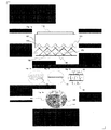
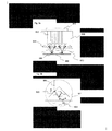
図1aに示すように、圧電性結晶(110)が、構造化された固体要素(100)上に接着されている。それらが組み合わさって共振器を形成する。この共振器は、共振周波数で電気的に駆動され、共振周波数は、共振器の構造共振の1つに対応しており、通例、10KHzから10MHzの間にある。固体要素は、共振器が基板(130)に近接して配置されると共にギャップが液体(170)で満たされた時に、特定の音響干渉パターン(120)を生成するよう構成される。かかる構造の典型的な例は、一連の三角溝(140)であり、各三角形の底辺および高さの典型的な寸法は、500マイクロメートルから10cmの間である。基板と共振器との間のギャップは、通例、約100ミクロンから約10mmであり、0.2mmから10mmが好ましく、0.2mmから3mmがより好ましい。 As shown in FIG. 1a, a piezoelectric crystal (110) is bonded onto a structured solid element (100). They combine to form a resonator. This resonator is electrically driven at a resonant frequency, which corresponds to one of the structural resonances of the resonator and is typically between 10 KHz and 10 MHz. The solid element is configured to generate a specific acoustic interference pattern (120) when the resonator is placed in proximity to the substrate (130) and the gap is filled with liquid (170). A typical example of such a structure is a series of triangular grooves (140), with typical dimensions of the base and height of each triangle being between 500 micrometers and 10 cm. The gap between the substrate and the resonator is typically about 100 microns to about 10 mm, preferably 0.2 mm to 10 mm, and more preferably 0.2 mm to 3 mm.
結果として得られる音響干渉パターン(120)は、液体内と、基板(130)の固体−液体界面とに、圧力振幅最大および最小の交互領域を形成する。かかる圧力最大領域(150)と、メカニズムの進行を、図1b〜図1dに示す。気泡(101)が、生成された音場に注入されると、そのサイズに応じて、圧力振幅最大領域および最小領域に振り分けられる。比較的弱い音場では、共振未満で駆動された気泡(印加された超音波場の駆動周波数が気泡の基本共振周波数(Minnaertの式によって計算される)未満であることを意味する)が、圧力振幅最大領域(102)に向かって移動する。気泡は、通例、圧力振幅最小領域(103)に向かって移動し始める臨界サイズ(Minnaertの式によって与えられる)に達するまで、圧力最大領域内で合体によって成長する。 The resulting acoustic interference pattern (120) forms alternating regions of maximum and minimum pressure amplitude within the liquid and at the solid-liquid interface of the substrate (130). Such a maximum pressure region (150) and the progression of the mechanism are shown in FIGS. When the bubbles (101) are injected into the generated sound field, they are distributed to the maximum pressure amplitude region and the minimum region according to the size. In a relatively weak sound field, a bubble driven below resonance (meaning that the drive frequency of the applied ultrasonic field is less than the fundamental resonance frequency of the bubble (calculated by the Minnaert equation)) It moves toward the maximum amplitude region (102). Bubbles typically grow by coalescence in the maximum pressure region until reaching a critical size (given by the Minnaert equation) that begins to move toward the minimum pressure amplitude region (103).
さらに、10-3バールから103バールの範囲の音圧で動作すると、(選択された動作周波数と共に)気泡活動を管理することが可能になることがわかった。なお、気泡活動は、気泡が、大量の気泡の崩壊にもつながる表面モード、表面不安定性、体積振動を引き起こすことを可能にするため、音響流、せん断応力を引き起こし、もしくは、1または複数の気体成分で液体−固体界面をリッチ化しうる。かかる活動の一例が図1eに示されており、印加された音場内で活性を有する気泡(104)が、干渉パターン内で移動し、軌道(105)をたどることで、せん断応力の局所的発生により基板から粒子状汚染物質(106)を除去しうる。 Furthermore, it has been found that operating with sound pressures in the range of 10 −3 bar to 10 3 bar makes it possible to manage bubble activity (along with the selected operating frequency). It should be noted that bubble activity causes acoustic flow, shear stress, or one or more gases to allow bubbles to cause surface modes, surface instabilities, and volume oscillations that also lead to the collapse of large quantities of bubbles. Components can enrich the liquid-solid interface. An example of such activity is shown in FIG. 1e, where bubbles (104) that are active in the applied sound field move within the interference pattern and follow the trajectory (105), resulting in local generation of shear stress. Can remove particulate contaminants (106) from the substrate.
本発明による装置は、好ましい実施形態において、半導体ウエハを処理するための枚葉式ウエハウェット処理ステーションである。 The apparatus according to the invention is, in a preferred embodiment, a single wafer wet processing station for processing semiconductor wafers.
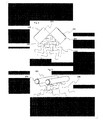
液体内および液体−固体界面に近接場干渉パターンを作り出すことは、気泡の配置および活性化で中心的な役割を果たす。かかる干渉パターンを作り出す別の方法が図2に示されており、その方法は、2つの独立した共振器の組み合わせに基づいている。第1の共振器は、固体要素(210)上に接着された圧電性結晶(230)からなり、同様に固体要素(200)上に接着された圧電性結晶(220)からなる第2の共振器に隣接して、1から45度の間の選択された角度で配置される。各共振器は、選択された動作周波数で液体に音波を放出し、放出された音波は再結合して、圧力振幅最小領域および最大領域(250)を備えた特定の干渉パターン(240)を生成する。 Creating near-field interference patterns within the liquid and at the liquid-solid interface plays a central role in bubble placement and activation. Another way of creating such an interference pattern is shown in FIG. 2, which is based on a combination of two independent resonators. The first resonator consists of a piezoelectric crystal (230) bonded onto the solid element (210), and also a second resonance consisting of a piezoelectric crystal (220) bonded onto the solid element (200). Adjacent to the vessel is placed at a selected angle between 1 and 45 degrees. Each resonator emits sound waves into the liquid at a selected operating frequency, and the emitted sound waves recombine to generate a specific interference pattern (240) with a pressure amplitude minimum region and a maximum region (250). To do.
変形例が図3に示されており、変形例では、圧電性結晶(310)によって駆動される2つのロッド(300)が互いに隣り合って配置されており、各ロッドの放出音波(330)が再結合して、特有の干渉パターンを形成する。 A modification is shown in FIG. 3, in which two rods (300) driven by a piezoelectric crystal (310) are arranged next to each other, and the emitted sound wave (330) of each rod is Recombine to form a unique interference pattern.
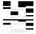
液体内の気泡のその場での不均一核生成に加えて、液体内に直接気泡を注入することが特に有益であり、それにより、キャビテーション閾値(通例、1バール未満)未満の音圧で動作することが可能になる。さらに、気泡のサイズ分布および気泡の内容物を、対象とする用途向けに、より容易に調整できる。音場へのかかる直接的な気泡注入の例を図4a〜図4cおよび図5に示す。 In addition to in situ heterogeneous nucleation of bubbles in the liquid, it is particularly beneficial to inject the bubbles directly into the liquid, thereby operating at sound pressures below the cavitation threshold (typically less than 1 bar) It becomes possible to do. Furthermore, the bubble size distribution and bubble contents can be more easily adjusted for the intended application. Examples of such direct bubble injection into the sound field are shown in FIGS. 4a-4c and FIG.
図4aは、圧電性結晶(410)が取り付けられ、一連の三角溝(440)を有する構造化された固体要素(400)の一例である。気泡注入装置(480)が、溝に隣接して配置される。気泡を含む流れ(F)が、最大および最小圧力振幅の領域に平行に、あるいは、最大60度の角度で、注入されることが好ましい。気泡流が移動して影響を与えうる典型的な長さ(L)は、最大5cmである。この例において、基板(w)が共振器の下で回転(R)し、共振器は、基板全体を処理するために平行移動(T)しうる。 FIG. 4a is an example of a structured solid element (400) with a piezoelectric crystal (410) attached and having a series of triangular grooves (440). A bubble injection device (480) is positioned adjacent to the groove. It is preferred that the bubble-containing flow (F) is injected parallel to the region of maximum and minimum pressure amplitude, or at an angle of up to 60 degrees. A typical length (L) that the bubble stream can move and affect is a maximum of 5 cm. In this example, the substrate (w) rotates (R) under the resonator, and the resonator can translate (T) to process the entire substrate.
図4bは、図4aの気泡マシン(480)の構造例を示す。この右前斜視図では、本体ハウジング(420)が示されており、1つの流入口(430)が設けられている。この流入口(430)は、約1mmから約20mmまでの内径を有し、外部の媒体供給ユニットに接続されており、図4cに示すように、加圧されたガス化媒体を気泡マシンの内部チャンバ(441)に供給する。注入口(450)、(421)が、傾斜した表面上に配置されている。5つの注入口が図示されているが、100mm2あたり約1から約30個まで様々な数の注入口が設けられてよく、100mm2あたり約16個が好ましい。注入口(450)は、約50μmから約500μmまでの直径を有するが、100から350μmの間が好ましく、内部チャンバ(441)と、気泡マシンが浸漬される周囲媒体(460)との間で媒体の圧力降下を引き起こすよう設計される。この周囲媒体(460)は、供給される媒体とは異なりうる。圧力降下は、供給された媒体に溶解した気体が脱気し始める範囲で選択されうる。脱気の結果として、多くの小さい気泡が生成され、周囲媒体(460)に注入される。 FIG. 4b shows an example structure of the bubble machine (480) of FIG. 4a. In the right front perspective view, the main body housing (420) is shown, and one inflow port (430) is provided. This inlet (430) has an inner diameter of about 1 mm to about 20 mm and is connected to an external media supply unit, allowing the pressurized gasification media to pass through the interior of the bubble machine as shown in FIG. 4c. Supply to chamber (441). Inlets (450), (421) are disposed on the inclined surface. Although five inlets are shown, various numbers of inlets from about 1 to about 30 per 100 mm 2 may be provided, with about 16 per 100 mm 2 being preferred. The inlet (450) has a diameter of about 50 μm to about 500 μm, preferably between 100 and 350 μm, and is a medium between the internal chamber (441) and the surrounding medium (460) in which the bubble machine is immersed. Designed to cause a pressure drop of. This ambient medium (460) may be different from the supplied medium. The pressure drop can be selected as long as the gas dissolved in the supplied medium begins to degas. As a result of degassing, many small bubbles are generated and injected into the surrounding medium (460).
本体ハウジング(420)、(401)の浸漬深さは、注入口(450)、(421)が周囲媒体(460)に浸漬されるように選択され、タンク内に浸漬するために約0.5mmから約350mmの間、または、2つの平行板の間に浸漬するために約0.3mmから約10mmの間に設定されることが好ましい。あるいは、本体ハウジング(420)、(401)は、周囲媒体(460)の中に完全に浸漬されてもよい。 The immersion depth of the body housings (420), (401) is selected so that the inlets (450), (421) are immersed in the surrounding medium (460) and about 0.5 mm for immersion in the tank. Preferably between about 0.3 mm and about 10 mm for immersion between two parallel plates. Alternatively, the body housing (420), (401) may be completely immersed in the surrounding medium (460).
別の設計が図5に示されており、その設計では、構造化された固体要素(500)が、一連の三角溝(540)および内蔵型気泡注入装置(580)を有する。処理液流入口(502)および処理液流出口(503)により、基板(W)が共振器の上または下で直線的に(M)または移動する間に、基板(W)の濡れおよび脱濡れが可能になる。気泡注入装置(580)は、内蔵型である点を除けば、装置(480)について述べた通りであってよい。 Another design is shown in FIG. 5, in which the structured solid element (500) has a series of triangular grooves (540) and a self-contained bubble injector (580). The processing liquid inlet (502) and the processing liquid outlet (503) allow the substrate (W) to wet and dewet while the substrate (W) moves (M) or moves linearly above or below the resonator. Is possible. The bubble injection device (580) may be as described for device (480), except that it is self-contained.
図6は、圧電性結晶(610)に結合された固体要素(600)の別の構造を示す。三角溝は、曲面(640)に置き換えられており、その曲面は、形状に応じて、液体内および固体−液体界面に干渉パターンを生成する。 FIG. 6 shows another structure of a solid element (600) bonded to a piezoelectric crystal (610). The triangular groove is replaced by a curved surface (640), and the curved surface generates an interference pattern in the liquid and in the solid-liquid interface depending on the shape.
さらに、図7および図8に示すように、平坦な共振器が必要な場合、幾何学的構造が、圧電性結晶(710および810)に結合された固体要素(700および800)内の共振器の内部空間(構造化された空間)に一体化されてもよい。かかる空間の断面形状は、円形開口部(720)から、楕円形構造、三角形構造(820)まで様々であってよい。これらの空間は、発射された音波の方向を変えるように特定の音響インピーダンスを有する液体で満たされてよい。 Further, as shown in FIGS. 7 and 8, when a flat resonator is required, the resonator is a resonator in a solid element (700 and 800) whose geometry is coupled to a piezoelectric crystal (710 and 810). May be integrated into the internal space (structured space). The cross-sectional shape of such a space may vary from a circular opening (720) to an elliptical structure or a triangular structure (820). These spaces may be filled with a liquid having a specific acoustic impedance to change the direction of the emitted sound wave.
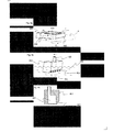
音波の経路の一例が、図9aに図示されており、さらに詳細に図9bに示されている。電気的に駆動された圧電性結晶(910)が、固体要素(900)内に音波(930)を発射する。異なる音響インピーダンスを有する領域(920)を音波が通る時、各界面で部分的に反射(R)され、部分的に透過(T)される。空間(920)内に存在する流体(921)の音響インピーダンスに応じて、入射波の屈折角度は、スネルの法則および透過係数によって計算できる。音波のこの部分の軌道(904)は、最終的に共振器および基板(960)の間の液体(970)内に入り、特有の干渉パターン(950)の生成を可能にする。 An example of a sound wave path is illustrated in FIG. 9a and in more detail in FIG. 9b. An electrically driven piezoelectric crystal (910) launches sound waves (930) into the solid element (900). When sound waves pass through regions (920) having different acoustic impedances, they are partially reflected (R) and partially transmitted (T) at each interface. Depending on the acoustic impedance of the fluid (921) present in the space (920), the refraction angle of the incident wave can be calculated by Snell's law and transmission coefficient. The trajectory (904) of this portion of the acoustic wave eventually enters the liquid (970) between the resonator and the substrate (960), allowing the generation of a unique interference pattern (950).
図10は、圧電性結晶1010および固体要素(1000)の組み合わせで構成され、結合液(1070)内に配置された共振器を示す。この結合液は、音響透過性の薄膜(1060)によって処理液(1090)から隔てられている。特定の干渉パターン(1050)が、両方の液体空間(結合空間および処理空間)内に確立されうる。基板(1030)を透過する音波を反射または吸収するために、基板(1030)の背面に、さらなる固体境界(1080)が配置されてよい。
FIG. 10 shows a resonator composed of a combination of a
本発明によると、蒸着およびエッチング速度の向上、選択性の向上、および、リンス効率の向上が可能である。本明細書に開示した原理に従って構築された本発明の実施形態は、基板の近くに短寿命の酸化種を生成してその濃度を高くすることができる。これは、従来技術とは対照的であり、従来技術では、通例、表面での気泡の活動が制限されている(面積あたり活性のある気泡の量が少ない)ため処理時間が長く不均一性の問題が生じ、そして、洗浄に関するプロセスウィンドウが小さい、具体的には、損傷を引き起こすウィンドウに対して洗浄ウィンドウが小さい。本発明は、さらに、距離の最適化(ウエハ−変換器)のための従来技術、および、キャビテーション開始閾値を超えるために必要な高電力での動作のための従来技術の必要性を低減する。 According to the present invention, it is possible to improve deposition and etching rates, improve selectivity, and improve rinsing efficiency. Embodiments of the present invention constructed in accordance with the principles disclosed herein can produce short-lived oxidized species near the substrate to increase its concentration. This is in contrast to the prior art, where the bubble activity on the surface is typically limited (the amount of active bubbles per area is small) and the processing time is long and non-uniform. Problems arise and the process window for cleaning is small, specifically the cleaning window is small relative to the window causing damage. The present invention further reduces the need for prior art for distance optimization (wafer-transducer) and prior art for operation at the high power required to exceed the cavitation start threshold.
本明細書に示された上述の説明および具体的な実施形態は、単に本発明およびその原理の例示であり、本発明の精神および範囲から逸脱することなく当業者によって変形および追加が容易になさうるため、本発明は添付の特許請求の範囲によってのみ限定されることを理解されたい。
本発明は、たとえば、以下のような態様で実現することもできる。
適用例1:
物品の表面を流体で処理するための装置であって、
物品を所定の向きに配置するよう構成されたホルダと、
前記物品に隣接する流体媒体を振動させるために配置された超音波またはメガソニックエネルギ源と、
前記液体に予め溶解された気体が気泡の形態で溶液から出てくるように、処理流体の圧力を低下させた後に前記超音波またはメガソニックエネルギ源の近くに前記処理流体を放出するよう構成された処理流体生成器と、を備え、
前記超音波またはメガソニックエネルギ源は、前記処理流体および前記物品の界面に圧力振幅最小および最大の領域を含む前記処理流体の干渉パターンを生成するよう構成されている、装置。
適用例2:
適用例1の装置であって、
前記処理流体生成器は、
流入口を設けられた本体ハウジングと、
前記本体に設けられた複数の注入口または注入スリットと、
前記流入口に結合された外部の液体媒体供給ユニットと、を備える、装置。
適用例3:
適用例1の装置であって、
前記超音波またはメガソニックエネルギ源は、約0.1mmから約10mmの幅wを有するギャップが形成されるように、前記物品が占めるべき空間に隣接して配置された共振器を備える、装置。
適用例4:
適用例1の装置であって、
前記超音波またはメガソニックエネルギ源は、前記超音波またはメガソニックエネルギを方向付けて前記干渉パターンを生成する一連の三角溝を有する共振器を備える、装置。
適用例5:
適用例1の装置であって、
前記超音波またはメガソニックエネルギ源は、モノリシックの本体上に取り付けられた複数の圧電素子を有すると共に、前記ホルダに載置された物品に対して斜めに向くように配置された共振器を備える、装置。
適用例6:
適用例1の装置であって、
前記超音波またはメガソニックエネルギ源は、前記処理流体とインピーダンスの異なる液体を含む少なくとも1つの内部空間を有する共振器を備える、装置。
適用例7:
適用例1の装置であって、
前記装置は、半導体ウエハを処理するための枚葉式ウエハウェット処理ステーションである、装置。
適用例8:
物品の表面を流体で処理するための装置であって、
所定の向きに前記物品を配置するよう構成されたホルダと、
前記物品に隣接する流体媒体を振動させるために配置された超音波またはメガソニックエネルギ源と、
前記超音波またはメガソニックエネルギ源の近くに、処理液体中に分散した気泡を含む処理流体を放出するように構成された処理流体生成器と、を備え、
前記気泡は1バール未満の音圧で生成され、
前記超音波またはメガソニックエネルギ源は、前記処理流体および前記物品の界面に圧力振幅最小および最大の領域を含む前記処理流体の干渉パターンを生成するよう構成されている、装置。
適用例9:
適用例8の装置であって、
前記超音波またはメガソニックエネルギ源は、前記超音波またはメガソニックエネルギを方向付けて前記干渉パターンを生成する一連の三角溝を有する共振器を備える、装置。
適用例10:
適用例8の装置であって、
前記超音波またはメガソニックエネルギ源は、モノリシックの本体上に取り付けられた複数の圧電素子を有すると共に、前記ホルダに載置された物品に対して斜めに向くように配置された共振器を備える、装置。
適用例11:
適用例8の装置であって、
前記装置は、半導体ウエハを処理するための枚葉式ウエハウェット処理ステーションである、装置。
適用例12:
物品の表面を流体で処理するための方法であって、
処理装置で処理される物品を所定の向きに配置する工程と、
前記物品に隣接する流体媒体を振動させるために超音波またはメガソニックエネルギを供給する工程と、
処理液体中に分散した気泡を含む処理流体を前記物品の表面の近くに供給する工程であって、前記気泡は1バール未満の音圧で生成される、工程と、を備え、
前記超音波またはメガソニックエネルギは、前記処理流体および前記物品の界面に圧力振幅最小および最大の領域を含む前記処理流体の干渉パターンを生成するように供給される、方法。
適用例13:
適用例12の方法であって、
前記処理装置は、半導体ウエハを処理するための枚葉式ウエハウェット処理ステーションである、方法。
適用例14:
適用例12の方法であって、
前記超音波またはメガソニックエネルギは、処理される前記物品の表面に対して斜めになった一連の傾斜面を有する共振器によって供給され、前記共振器の前記傾斜面は、前記共振器によって生成された音波を互いに干渉させる、方法。
The foregoing description and specific embodiments presented herein are merely illustrative of the invention and its principles and may be easily modified and added by those skilled in the art without departing from the spirit and scope of the invention. Therefore, it should be understood that the invention is limited only by the accompanying claims.
The present invention can also be realized in the following manner, for example.
Application example 1:
An apparatus for treating a surface of an article with a fluid,
A holder configured to place the article in a predetermined orientation;
An ultrasonic or megasonic energy source arranged to vibrate a fluid medium adjacent to the article;
Configured to release the processing fluid in proximity to the ultrasonic or megasonic energy source after reducing the pressure of the processing fluid such that gas pre-dissolved in the liquid emerges from the solution in the form of bubbles. A treatment fluid generator,
The apparatus wherein the ultrasonic or megasonic energy source is configured to generate an interference pattern of the processing fluid that includes minimum and maximum regions of pressure amplitude at the interface of the processing fluid and the article.
Application example 2:
It is an apparatus of application example 1,
The processing fluid generator includes:
A body housing provided with an inlet,
A plurality of injection ports or injection slits provided in the main body;
An external liquid medium supply unit coupled to the inlet.
Application example 3:
It is an apparatus of application example 1,
The ultrasonic or megasonic energy source comprises a resonator disposed adjacent to a space to be occupied by the article such that a gap having a width w of about 0.1 mm to about 10 mm is formed.
Application example 4:
It is an apparatus of application example 1,
The apparatus, wherein the ultrasonic or megasonic energy source comprises a resonator having a series of triangular grooves that direct the ultrasonic or megasonic energy to generate the interference pattern.
Application example 5:
It is an apparatus of application example 1,
The ultrasonic or megasonic energy source includes a plurality of piezoelectric elements mounted on a monolithic main body, and includes a resonator disposed so as to be inclined with respect to an article placed on the holder. apparatus.
Application example 6:
It is an apparatus of application example 1,
The ultrasonic or megasonic energy source comprises a resonator having at least one internal space containing a liquid having a different impedance from the processing fluid.
Application example 7:
It is an apparatus of application example 1,
The apparatus is a single wafer wet processing station for processing semiconductor wafers.
Application Example 8:
An apparatus for treating a surface of an article with a fluid,
A holder configured to place the article in a predetermined orientation;
An ultrasonic or megasonic energy source arranged to vibrate a fluid medium adjacent to the article;
A treatment fluid generator configured to emit a treatment fluid containing bubbles dispersed in a treatment liquid proximate to the ultrasonic or megasonic energy source;
The bubbles are generated with a sound pressure of less than 1 bar,
The apparatus wherein the ultrasonic or megasonic energy source is configured to generate an interference pattern of the processing fluid that includes minimum and maximum regions of pressure amplitude at the interface of the processing fluid and the article.
Application example 9:
It is a device of application example 8,
The apparatus, wherein the ultrasonic or megasonic energy source comprises a resonator having a series of triangular grooves that direct the ultrasonic or megasonic energy to generate the interference pattern.
Application Example 10:
It is a device of application example 8,
The ultrasonic or megasonic energy source includes a plurality of piezoelectric elements mounted on a monolithic main body, and includes a resonator disposed so as to be inclined with respect to an article placed on the holder. apparatus.
Application Example 11:
It is a device of application example 8,
The apparatus is a single wafer wet processing station for processing semiconductor wafers.
Application Example 12:
A method for treating a surface of an article with a fluid comprising:
Arranging an article to be processed by the processing apparatus in a predetermined direction;
Supplying ultrasonic or megasonic energy to vibrate a fluid medium adjacent to the article;
Providing a treatment fluid comprising bubbles dispersed in a treatment liquid near the surface of the article, wherein the bubbles are generated with an acoustic pressure of less than 1 bar, and
The method wherein the ultrasonic or megasonic energy is provided to generate an interference pattern of the processing fluid that includes pressure amplitude minimum and maximum regions at the interface of the processing fluid and the article.
Application Example 13:
It is the method of application example 12,
The method, wherein the processing apparatus is a single wafer wet processing station for processing semiconductor wafers.
Application Example 14:
It is the method of application example 12,
The ultrasonic or megasonic energy is supplied by a resonator having a series of inclined surfaces that are inclined relative to the surface of the article to be processed, the inclined surfaces of the resonator being generated by the resonator. A method of causing sound waves to interfere with each other.
Claims (12)
物品を所定の向きに配置するよう構成されたホルダと、
前記物品に隣接する流体媒体を振動させるために配置された超音波またはメガソニックエネルギ源と、
前記流体としての液体に予め溶解された気体が気泡の形態で溶液から出てくるように、処理流体の圧力を低下させた後に前記超音波またはメガソニックエネルギ源の近くに前記処理流体を放出するよう構成された処理流体生成器と、を備え、
前記超音波またはメガソニックエネルギ源は、前記処理流体および前記物品の界面に圧力振幅最小および最大の領域を含む前記処理流体の干渉パターンを生成するよう構成されており、
前記処理流体生成器は、さらに、前記圧力振幅最小および最大の領域に平行に、または最大60度の角度で、前記処理流体を注入するように構成されており、
前記超音波またはメガソニックエネルギ源は、約0.1mmから約10mmの幅wを有するギャップが形成されるように、前記物品が占めるべき空間に隣接して配置された共振器を備え、
前記処理流体生成器は、
流入口を設けられた本体ハウジングと、
前記本体ハウジングに設けられた複数の注入口であって、それぞれ50μmから500μmの直径を有し、前記本体ハウジング内のチャンバ内の流体媒体と、前記本体ハウジングが浸漬される周囲の流体媒体と、の間において、前記圧力の低下を生じさせるように設計された、複数の注入口と、
前記流入口に結合された外部の液体媒体供給ユニットと、を備える、装置。 An apparatus for treating a surface of an article with a fluid,
A holder configured to place the article in a predetermined orientation;
An ultrasonic or megasonic energy source arranged to vibrate a fluid medium adjacent to the article;
Release the processing fluid near the ultrasonic or megasonic energy source after reducing the pressure of the processing fluid so that the gas pre-dissolved in the liquid as the fluid emerges from the solution in the form of bubbles And a processing fluid generator configured to
The ultrasonic or megasonic energy source is configured to generate an interference pattern of the processing fluid that includes minimum and maximum regions of pressure amplitude at the interface of the processing fluid and the article;
The processing fluid generator is further configured to inject the processing fluid parallel to the pressure amplitude minimum and maximum regions or at an angle of up to 60 degrees;
The ultrasonic or megasonic energy source comprises a resonator disposed adjacent to a space to be occupied by the article such that a gap having a width w of about 0.1 mm to about 10 mm is formed ;
The processing fluid generator includes:
A body housing provided with an inlet,
A plurality of inlets provided in the body housing , each having a diameter of 50 μm to 500 μm, a fluid medium in a chamber in the body housing, and a surrounding fluid medium in which the body housing is immersed; A plurality of inlets designed to cause the pressure drop between
An external liquid medium supply unit coupled to the inlet.
前記超音波またはメガソニックエネルギ源は、前記超音波またはメガソニックエネルギを方向付けて前記干渉パターンを生成する一連の三角溝を有する共振器を備える、装置。 The apparatus of claim 1, comprising:
The apparatus, wherein the ultrasonic or megasonic energy source comprises a resonator having a series of triangular grooves that direct the ultrasonic or megasonic energy to generate the interference pattern.
前記超音波またはメガソニックエネルギ源は、モノリシックの本体上に取り付けられた複数の圧電素子を有すると共に、前記ホルダに載置された物品に対して斜めに向くように配置された共振器を備える、装置。 The apparatus of claim 1, comprising:
The ultrasonic or megasonic energy source includes a plurality of piezoelectric elements mounted on a monolithic main body, and includes a resonator disposed so as to be inclined with respect to an article placed on the holder. apparatus.
前記超音波またはメガソニックエネルギ源は、前記処理流体とインピーダンスの異なる液体を含む少なくとも1つの内部空間を有する共振器を備える、装置。 The apparatus of claim 1, comprising:
The ultrasonic or megasonic energy source comprises a resonator having at least one internal space containing a liquid having a different impedance from the processing fluid.
前記装置は、半導体ウエハを処理するための枚葉式ウエハウェット処理ステーションである、装置。 The apparatus of claim 1, comprising:
The apparatus is a single wafer wet processing station for processing semiconductor wafers.
所定の向きに前記物品を配置するよう構成されたホルダと、
前記物品に隣接する流体媒体を振動させるために配置された超音波またはメガソニックエネルギ源と、
前記超音波またはメガソニックエネルギ源の近くに、処理液体中に分散した気泡を含む処理流体を放出するように構成された処理流体生成器と、を備え、
前記気泡は1バール未満の音圧で生成され、
前記超音波またはメガソニックエネルギ源は、前記処理流体および前記物品の界面に圧力振幅最小および最大の領域を含む前記処理流体の干渉パターンを生成するよう構成されており、
前記処理流体生成器は、さらに、前記圧力振幅最小および最大の領域に平行に、または最大60度の角度で、前記処理流体を注入するように構成されており、
前記超音波またはメガソニックエネルギ源は、約0.1mmから約10mmの幅wを有するギャップが形成されるように、前記物品が占めるべき空間に隣接して配置された共振器を備え、
前記処理流体生成器は、
流入口を設けられた本体ハウジングと、
前記本体ハウジングに設けられた複数の注入口であって、それぞれ50μmから500μmの直径を有し、前記液体に予め溶解された気体が気泡の形態で流体媒体から出てくるように、前記本体ハウジング内のチャンバ内の流体媒体と、前記本体ハウジングが浸漬される周囲の流体媒体と、の間において、圧力の低下を生じさせるように設計された、複数の注入口と、
前記流入口に結合された外部の液体媒体供給ユニットと、を備える、装置。 An apparatus for treating a surface of an article with a fluid,
A holder configured to place the article in a predetermined orientation;
An ultrasonic or megasonic energy source arranged to vibrate a fluid medium adjacent to the article;
A treatment fluid generator configured to emit a treatment fluid containing bubbles dispersed in a treatment liquid proximate to the ultrasonic or megasonic energy source;
The bubbles are generated with a sound pressure of less than 1 bar,
The ultrasonic or megasonic energy source is configured to generate an interference pattern of the processing fluid that includes minimum and maximum regions of pressure amplitude at the interface of the processing fluid and the article;
The processing fluid generator is further configured to inject the processing fluid parallel to the pressure amplitude minimum and maximum regions or at an angle of up to 60 degrees;
The ultrasonic or megasonic energy source comprises a resonator disposed adjacent to a space to be occupied by the article such that a gap having a width w of about 0.1 mm to about 10 mm is formed ;
The processing fluid generator includes:
A body housing provided with an inlet,
A plurality of inlets provided in the main body housing , each having a diameter of 50 μm to 500 μm, so that the gas previously dissolved in the liquid comes out of the fluid medium in the form of bubbles. A plurality of inlets designed to cause a drop in pressure between the fluid medium in the inner chamber and the surrounding fluid medium in which the body housing is immersed ;
An external liquid medium supply unit coupled to the inlet.
前記超音波またはメガソニックエネルギ源は、前記超音波またはメガソニックエネルギを方向付けて前記干渉パターンを生成する一連の三角溝を有する共振器を備える、装置。 The apparatus according to claim 6, comprising:
The apparatus, wherein the ultrasonic or megasonic energy source comprises a resonator having a series of triangular grooves that direct the ultrasonic or megasonic energy to generate the interference pattern.
前記超音波またはメガソニックエネルギ源は、モノリシックの本体上に取り付けられた複数の圧電素子を有すると共に、前記ホルダに載置された物品に対して斜めに向くように配置された共振器を備える、装置。 The apparatus according to claim 6, comprising:
The ultrasonic or megasonic energy source includes a plurality of piezoelectric elements mounted on a monolithic main body, and includes a resonator disposed so as to be inclined with respect to an article placed on the holder. apparatus.
前記装置は、半導体ウエハを処理するための枚葉式ウエハウェット処理ステーションである、装置。 The apparatus according to claim 6, comprising:
The apparatus is a single wafer wet processing station for processing semiconductor wafers.
処理装置で処理される物品を所定の向きに配置する工程と、
前記物品に隣接する流体媒体を振動させるために超音波またはメガソニックエネルギを供給する工程と、
処理液体中に分散した気泡を含む処理流体を前記物品の表面の近くに供給する工程であって、前記気泡は1バール未満の音圧で生成される、工程と、を備え、
前記超音波またはメガソニックエネルギは、前記処理流体および前記物品の界面に圧力振幅最小および最大の領域を含む前記処理流体の干渉パターンを生成するように供給され、
前記超音波またはメガソニックエネルギ源は、約0.1mmから約10mmの幅wを有するギャップが形成されるように、前記物品が占めるべき空間に隣接して配置された共振器を備え、
前記処理流体を前記物品の表面の近くに供給する工程は、
流入口を設けられた本体ハウジングと、
前記本体ハウジングに設けられた複数の注入口であって、それぞれ50μmから500μmの直径を有する複数の注入口と、
前記流入口に結合された外部の液体媒体供給ユニットと、を備える処理流体生成器において、
前記液体に予め溶解された気体が気泡の形態で流体媒体から出てくるように、前記本体ハウジング内のチャンバ内の流体媒体と、前記本体ハウジングが浸漬される周囲の流体媒体と、の間において、圧力の低下を生じさせる工程を含む、方法。 A method for treating a surface of an article with a fluid comprising:
Arranging an article to be processed by the processing apparatus in a predetermined direction;
Supplying ultrasonic or megasonic energy to vibrate a fluid medium adjacent to the article;
Providing a treatment fluid comprising bubbles dispersed in a treatment liquid near the surface of the article, wherein the bubbles are generated with an acoustic pressure of less than 1 bar, and
The ultrasonic or megasonic energy is provided to generate an interference pattern of the processing fluid comprising pressure amplitude minimum and maximum regions at the interface of the processing fluid and the article;
The ultrasonic or megasonic energy source comprises a resonator disposed adjacent to a space to be occupied by the article such that a gap having a width w of about 0.1 mm to about 10 mm is formed ;
Supplying the processing fluid near the surface of the article comprises:
A body housing provided with an inlet,
A plurality of inlets provided in the main body housing , each having a diameter of 50 μm to 500 μm ;
A processing fluid generator comprising: an external liquid medium supply unit coupled to the inlet ;
Between the fluid medium in the chamber in the body housing and the surrounding fluid medium in which the body housing is immersed, so that the gas pre-dissolved in the liquid emerges from the fluid medium in the form of bubbles. Producing a drop in pressure .
前記処理装置は、半導体ウエハを処理するための枚葉式ウエハウェット処理ステーションである、方法。 The method of claim 10, comprising:
The method, wherein the processing apparatus is a single wafer wet processing station for processing semiconductor wafers.
前記超音波またはメガソニックエネルギは、処理される前記物品の表面に対して斜めになった一連の傾斜面を有する共振器によって供給され、前記共振器の前記傾斜面は、前記共振器によって生成された音波を互いに干渉させる、方法。 The method of claim 10, comprising:
The ultrasonic or megasonic energy is supplied by a resonator having a series of inclined surfaces that are inclined relative to the surface of the article to be processed, the inclined surfaces of the resonator being generated by the resonator. A method of causing sound waves to interfere with each other.
Applications Claiming Priority (3)
| Application Number | Priority Date | Filing Date | Title |
|---|---|---|---|
| US12/889,975 | 2010-09-24 | ||
| US12/889,975 US9662686B2 (en) | 2010-09-24 | 2010-09-24 | Ultrasonic cleaning method and apparatus |
| PCT/IB2011/054195 WO2012038933A2 (en) | 2010-09-24 | 2011-09-23 | Improved ultrasonic cleaning method and apparatus |
Publications (3)
| Publication Number | Publication Date |
|---|---|
| JP2013543653A JP2013543653A (en) | 2013-12-05 |
| JP2013543653A5 JP2013543653A5 (en) | 2014-11-13 |
| JP5974009B2 true JP5974009B2 (en) | 2016-08-23 |
Family
ID=45869372
Family Applications (1)
| Application Number | Title | Priority Date | Filing Date |
|---|---|---|---|
| JP2013529756A Active JP5974009B2 (en) | 2010-09-24 | 2011-09-23 | Improved ultrasonic cleaning method and apparatus |
Country Status (7)
| Country | Link |
|---|---|
| US (1) | US9662686B2 (en) |
| JP (1) | JP5974009B2 (en) |
| KR (1) | KR20130107287A (en) |
| CN (1) | CN103118810B (en) |
| SG (1) | SG188535A1 (en) |
| TW (1) | TWI473668B (en) |
| WO (1) | WO2012038933A2 (en) |
Families Citing this family (9)
| Publication number | Priority date | Publication date | Assignee | Title |
|---|---|---|---|---|
| US10391526B2 (en) | 2013-12-12 | 2019-08-27 | Lam Research Corporation | Electrostatic chuck cleaning fixture |
| TWI698291B (en) * | 2016-11-02 | 2020-07-11 | 大陸商盛美半導體設備(上海)股份有限公司 | Substrate cleaning method and cleaning device |
| JP6554128B2 (en) | 2017-02-28 | 2019-07-31 | 株式会社Subaru | Manufacturing method of fiber reinforced composite material |
| JP6418357B1 (en) * | 2017-05-26 | 2018-11-07 | 住友電気工業株式会社 | GaAs substrate and manufacturing method thereof |
| CN107570482A (en) * | 2017-07-06 | 2018-01-12 | 天津大学 | The removal device and method of the non-specific adsorption thing at interface |
| JP6715226B2 (en) | 2017-10-25 | 2020-07-01 | 株式会社Subaru | Composite material forming jig and composite material forming method |
| CN110560425B (en) * | 2019-09-20 | 2021-01-29 | 深圳先进技术研究院 | Ultrasonic cleaning device, cleaning method and application thereof |
| US20220184670A1 (en) * | 2020-12-16 | 2022-06-16 | The Boeing Company | Flexible cavitation apparatus |
| CN116581067B (en) * | 2023-07-12 | 2023-09-22 | 北京东方金荣超声电器有限公司 | Control method of megasonic system based on wet processing of device |
Family Cites Families (17)
| Publication number | Priority date | Publication date | Assignee | Title |
|---|---|---|---|---|
| US5625249A (en) | 1994-07-20 | 1997-04-29 | Submicron Systems, Inc. | Megasonic cleaning system |
| JP3511441B2 (en) | 1996-11-29 | 2004-03-29 | 忠弘 大見 | Liquid-saving liquid supply nozzle, wet processing apparatus, and wet processing method used for wet processing including cleaning, etching, development, and peeling |
| US6290778B1 (en) | 1998-08-12 | 2001-09-18 | Hudson Technologies, Inc. | Method and apparatus for sonic cleaning of heat exchangers |
| JP4608748B2 (en) * | 1999-08-05 | 2011-01-12 | 東京エレクトロン株式会社 | Cleaning device, cleaning system and cleaning method |
| US6729339B1 (en) * | 2002-06-28 | 2004-05-04 | Lam Research Corporation | Method and apparatus for cooling a resonator of a megasonic transducer |
| US7240679B2 (en) | 2002-09-30 | 2007-07-10 | Lam Research Corporation | System for substrate processing with meniscus, vacuum, IPA vapor, drying manifold |
| WO2004112093A2 (en) | 2003-06-06 | 2004-12-23 | P.C.T. Systems, Inc. | Method and apparatus to process substrates with megasonic energy |
| CN1822905A (en) | 2003-06-06 | 2006-08-23 | P.C.T.系统公司 | Method and apparatus to process substrates with megasonic energy |
| WO2006001293A1 (en) | 2004-06-29 | 2006-01-05 | Kagoshima Supersonic Technical Laboratory Co., Ltd. | Ultrasonic cleaning method and apparatus |
| US7392814B2 (en) | 2004-12-24 | 2008-07-01 | Dainippon Screen Mfg. Co., Ltd. | Substrate processing apparatus and method |
| TWI259110B (en) | 2005-09-22 | 2006-08-01 | Delta Electronics Inc | Ultrasonic cleaning system and method |
| JP4652959B2 (en) * | 2005-11-30 | 2011-03-16 | 芝浦メカトロニクス株式会社 | Substrate processing equipment |
| KR100710803B1 (en) * | 2006-01-23 | 2007-04-23 | 삼성전자주식회사 | Apparatus for cleaning substrates |
| JP2008021672A (en) * | 2006-07-10 | 2008-01-31 | Sony Corp | Ultrasonic cleaning method and cleaning device using gas supersaturation solution |
| WO2008008921A2 (en) * | 2006-07-12 | 2008-01-17 | Akrion Technologies, Inc. | Tranducer assembly incorporating a transmitter having through holes, and method of cleaning |
| KR100931856B1 (en) | 2007-08-24 | 2009-12-15 | 세메스 주식회사 | Substrate Cleaning Apparatus and Substrate Cleaning Method |
| JP2009178440A (en) | 2008-01-31 | 2009-08-13 | Sammy Corp | Presentation display device and game machine |
-
2010
- 2010-09-24 US US12/889,975 patent/US9662686B2/en active Active
-
2011
- 2011-09-22 TW TW100134216A patent/TWI473668B/en active
- 2011-09-23 SG SG2013018825A patent/SG188535A1/en unknown
- 2011-09-23 KR KR1020137007408A patent/KR20130107287A/en not_active Application Discontinuation
- 2011-09-23 CN CN201180045874.3A patent/CN103118810B/en active Active
- 2011-09-23 JP JP2013529756A patent/JP5974009B2/en active Active
- 2011-09-23 WO PCT/IB2011/054195 patent/WO2012038933A2/en active Application Filing
Also Published As
| Publication number | Publication date |
|---|---|
| WO2012038933A2 (en) | 2012-03-29 |
| TWI473668B (en) | 2015-02-21 |
| CN103118810A (en) | 2013-05-22 |
| JP2013543653A (en) | 2013-12-05 |
| US20120073596A1 (en) | 2012-03-29 |
| KR20130107287A (en) | 2013-10-01 |
| CN103118810B (en) | 2015-07-01 |
| TW201223652A (en) | 2012-06-16 |
| US9662686B2 (en) | 2017-05-30 |
| SG188535A1 (en) | 2013-05-31 |
| WO2012038933A3 (en) | 2012-07-12 |
Similar Documents
| Publication | Publication Date | Title |
|---|---|---|
| JP5974009B2 (en) | Improved ultrasonic cleaning method and apparatus | |
| JP5836973B2 (en) | Improved ultrasonic cleaning method and apparatus | |
| JP2007311756A (en) | Ultrasonic cleaner and ultrasonic cleaning method | |
| JP2011115793A (en) | Method and apparatus for washing surface | |
| JP2007250726A (en) | Cleaning method, device and program of substrate, and recording medium | |
| JP2011077144A (en) | Substrate processing apparatus and method of processing substrate | |
| US8486199B2 (en) | Ultrasonic cleaning method and apparatus | |
| TWI358761B (en) | ||
| JP2008188563A (en) | Ultrasonic cleaning method | |
| JP5015717B2 (en) | Substrate cleaning device | |
| JP4533406B2 (en) | Ultrasonic cleaning apparatus and ultrasonic cleaning method | |
| JP2020014989A (en) | Degassed fine bubble liquid generating device, degassed fine bubble liquid generating method, ultrasonic treatment device and ultrasonic treatment method | |
| JP2005158913A (en) | Ultrasonic nozzle and substrate treatment apparatus | |
| JP4957277B2 (en) | Cleaning device and cleaning method | |
| JP2005169278A (en) | Ultrasonic washing nozzle and ultrasonic washing apparatus | |
| JP2010238744A (en) | Ultrasonic cleaning unit, and ultrasonic cleaning device | |
| Suzuki et al. | Novel ultrasonic cleaning equipment using waveguide mode | |
| JP5592734B2 (en) | Ultrasonic cleaning apparatus and ultrasonic cleaning method | |
| KR20100054458A (en) | Supersonic nozzle and wafer cleaning apparatus compring the same | |
| US20130319472A1 (en) | Method and apparatus for processing wafer-shaped articles | |
| JP2005085978A (en) | Single-wafer type cleaning method and cleaning device | |
| JP6043084B2 (en) | Semiconductor substrate cleaning method and cleaning apparatus | |
| JP5169264B2 (en) | Cleaning device | |
| JPH01304089A (en) | Ultrasonic washing apparatus | |
| JP2006095458A (en) | Single wafer processing cleaning method and single wafer processing cleaning apparatus |
Legal Events
| Date | Code | Title | Description |
|---|---|---|---|
| A521 | Request for written amendment filed |
Free format text: JAPANESE INTERMEDIATE CODE: A523 Effective date: 20140922 |
|
| A621 | Written request for application examination |
Free format text: JAPANESE INTERMEDIATE CODE: A621 Effective date: 20140922 |
|
| A131 | Notification of reasons for refusal |
Free format text: JAPANESE INTERMEDIATE CODE: A131 Effective date: 20151020 |
|
| A977 | Report on retrieval |
Free format text: JAPANESE INTERMEDIATE CODE: A971007 Effective date: 20151021 |
|
| A521 | Request for written amendment filed |
Free format text: JAPANESE INTERMEDIATE CODE: A523 Effective date: 20160119 |
|
| TRDD | Decision of grant or rejection written | ||
| A01 | Written decision to grant a patent or to grant a registration (utility model) |
Free format text: JAPANESE INTERMEDIATE CODE: A01 Effective date: 20160628 |
|
| A61 | First payment of annual fees (during grant procedure) |
Free format text: JAPANESE INTERMEDIATE CODE: A61 Effective date: 20160715 |
|
| R150 | Certificate of patent or registration of utility model |
Ref document number: 5974009 Country of ref document: JP Free format text: JAPANESE INTERMEDIATE CODE: R150 |
|
| R250 | Receipt of annual fees |
Free format text: JAPANESE INTERMEDIATE CODE: R250 |
|
| R250 | Receipt of annual fees |
Free format text: JAPANESE INTERMEDIATE CODE: R250 |
|
| R250 | Receipt of annual fees |
Free format text: JAPANESE INTERMEDIATE CODE: R250 |
|
| R250 | Receipt of annual fees |
Free format text: JAPANESE INTERMEDIATE CODE: R250 |
|
| R250 | Receipt of annual fees |
Free format text: JAPANESE INTERMEDIATE CODE: R250 |