JP5663674B2 - Spine implant, pretreatment instrument and method of use - Google Patents
Spine implant, pretreatment instrument and method of use Download PDFInfo
- Publication number
- JP5663674B2 JP5663674B2 JP2013557844A JP2013557844A JP5663674B2 JP 5663674 B2 JP5663674 B2 JP 5663674B2 JP 2013557844 A JP2013557844 A JP 2013557844A JP 2013557844 A JP2013557844 A JP 2013557844A JP 5663674 B2 JP5663674 B2 JP 5663674B2
- Authority
- JP
- Japan
- Prior art keywords
- intervertebral
- elements
- implant
- disc implant
- central region
- Prior art date
- Legal status (The legal status is an assumption and is not a legal conclusion. Google has not performed a legal analysis and makes no representation as to the accuracy of the status listed.)
- Expired - Fee Related
Links
Images


Classifications
-
- A—HUMAN NECESSITIES
- A61—MEDICAL OR VETERINARY SCIENCE; HYGIENE
- A61F—FILTERS IMPLANTABLE INTO BLOOD VESSELS; PROSTHESES; DEVICES PROVIDING PATENCY TO, OR PREVENTING COLLAPSING OF, TUBULAR STRUCTURES OF THE BODY, e.g. STENTS; ORTHOPAEDIC, NURSING OR CONTRACEPTIVE DEVICES; FOMENTATION; TREATMENT OR PROTECTION OF EYES OR EARS; BANDAGES, DRESSINGS OR ABSORBENT PADS; FIRST-AID KITS
- A61F2/00—Filters implantable into blood vessels; Prostheses, i.e. artificial substitutes or replacements for parts of the body; Appliances for connecting them with the body; Devices providing patency to, or preventing collapsing of, tubular structures of the body, e.g. stents
- A61F2/02—Prostheses implantable into the body
- A61F2/30—Joints
- A61F2/44—Joints for the spine, e.g. vertebrae, spinal discs
- A61F2/4455—Joints for the spine, e.g. vertebrae, spinal discs for the fusion of spinal bodies, e.g. intervertebral fusion of adjacent spinal bodies, e.g. fusion cages
- A61F2/4465—Joints for the spine, e.g. vertebrae, spinal discs for the fusion of spinal bodies, e.g. intervertebral fusion of adjacent spinal bodies, e.g. fusion cages having a circular or kidney shaped cross-section substantially perpendicular to the axis of the spine
-
- A—HUMAN NECESSITIES
- A61—MEDICAL OR VETERINARY SCIENCE; HYGIENE
- A61B—DIAGNOSIS; SURGERY; IDENTIFICATION
- A61B17/00—Surgical instruments, devices or methods, e.g. tourniquets
- A61B17/16—Bone cutting, breaking or removal means other than saws, e.g. Osteoclasts; Drills or chisels for bones; Trepans
- A61B17/1662—Bone cutting, breaking or removal means other than saws, e.g. Osteoclasts; Drills or chisels for bones; Trepans for particular parts of the body
- A61B17/1671—Bone cutting, breaking or removal means other than saws, e.g. Osteoclasts; Drills or chisels for bones; Trepans for particular parts of the body for the spine
-
- A—HUMAN NECESSITIES
- A61—MEDICAL OR VETERINARY SCIENCE; HYGIENE
- A61F—FILTERS IMPLANTABLE INTO BLOOD VESSELS; PROSTHESES; DEVICES PROVIDING PATENCY TO, OR PREVENTING COLLAPSING OF, TUBULAR STRUCTURES OF THE BODY, e.g. STENTS; ORTHOPAEDIC, NURSING OR CONTRACEPTIVE DEVICES; FOMENTATION; TREATMENT OR PROTECTION OF EYES OR EARS; BANDAGES, DRESSINGS OR ABSORBENT PADS; FIRST-AID KITS
- A61F2/00—Filters implantable into blood vessels; Prostheses, i.e. artificial substitutes or replacements for parts of the body; Appliances for connecting them with the body; Devices providing patency to, or preventing collapsing of, tubular structures of the body, e.g. stents
- A61F2/02—Prostheses implantable into the body
- A61F2/30—Joints
- A61F2/44—Joints for the spine, e.g. vertebrae, spinal discs
- A61F2/442—Intervertebral or spinal discs, e.g. resilient
- A61F2/4425—Intervertebral or spinal discs, e.g. resilient made of articulated components
-
- A—HUMAN NECESSITIES
- A61—MEDICAL OR VETERINARY SCIENCE; HYGIENE
- A61F—FILTERS IMPLANTABLE INTO BLOOD VESSELS; PROSTHESES; DEVICES PROVIDING PATENCY TO, OR PREVENTING COLLAPSING OF, TUBULAR STRUCTURES OF THE BODY, e.g. STENTS; ORTHOPAEDIC, NURSING OR CONTRACEPTIVE DEVICES; FOMENTATION; TREATMENT OR PROTECTION OF EYES OR EARS; BANDAGES, DRESSINGS OR ABSORBENT PADS; FIRST-AID KITS
- A61F2/00—Filters implantable into blood vessels; Prostheses, i.e. artificial substitutes or replacements for parts of the body; Appliances for connecting them with the body; Devices providing patency to, or preventing collapsing of, tubular structures of the body, e.g. stents
- A61F2/02—Prostheses implantable into the body
- A61F2/30—Joints
- A61F2/46—Special tools or methods for implanting or extracting artificial joints, accessories, bone grafts or substitutes, or particular adaptations therefor
- A61F2/4684—Trial or dummy prostheses
-
- H—ELECTRICITY
- H04—ELECTRIC COMMUNICATION TECHNIQUE
- H04N—PICTORIAL COMMUNICATION, e.g. TELEVISION
- H04N7/00—Television systems
- H04N7/01—Conversion of standards, e.g. involving analogue television standards or digital television standards processed at pixel level
- H04N7/0135—Conversion of standards, e.g. involving analogue television standards or digital television standards processed at pixel level involving interpolation processes
- H04N7/014—Conversion of standards, e.g. involving analogue television standards or digital television standards processed at pixel level involving interpolation processes involving the use of motion vectors
-
- H—ELECTRICITY
- H04—ELECTRIC COMMUNICATION TECHNIQUE
- H04N—PICTORIAL COMMUNICATION, e.g. TELEVISION
- H04N7/00—Television systems
- H04N7/01—Conversion of standards, e.g. involving analogue television standards or digital television standards processed at pixel level
- H04N7/0135—Conversion of standards, e.g. involving analogue television standards or digital television standards processed at pixel level involving interpolation processes
- H04N7/0145—Conversion of standards, e.g. involving analogue television standards or digital television standards processed at pixel level involving interpolation processes the interpolation being class adaptive, i.e. it uses the information of class which is determined for a pixel based upon certain characteristics of the neighbouring pixels
-
- A—HUMAN NECESSITIES
- A61—MEDICAL OR VETERINARY SCIENCE; HYGIENE
- A61F—FILTERS IMPLANTABLE INTO BLOOD VESSELS; PROSTHESES; DEVICES PROVIDING PATENCY TO, OR PREVENTING COLLAPSING OF, TUBULAR STRUCTURES OF THE BODY, e.g. STENTS; ORTHOPAEDIC, NURSING OR CONTRACEPTIVE DEVICES; FOMENTATION; TREATMENT OR PROTECTION OF EYES OR EARS; BANDAGES, DRESSINGS OR ABSORBENT PADS; FIRST-AID KITS
- A61F2/00—Filters implantable into blood vessels; Prostheses, i.e. artificial substitutes or replacements for parts of the body; Appliances for connecting them with the body; Devices providing patency to, or preventing collapsing of, tubular structures of the body, e.g. stents
- A61F2/02—Prostheses implantable into the body
- A61F2/30—Joints
- A61F2/30721—Accessories
- A61F2/30744—End caps, e.g. for closing an endoprosthetic cavity
-
- A—HUMAN NECESSITIES
- A61—MEDICAL OR VETERINARY SCIENCE; HYGIENE
- A61F—FILTERS IMPLANTABLE INTO BLOOD VESSELS; PROSTHESES; DEVICES PROVIDING PATENCY TO, OR PREVENTING COLLAPSING OF, TUBULAR STRUCTURES OF THE BODY, e.g. STENTS; ORTHOPAEDIC, NURSING OR CONTRACEPTIVE DEVICES; FOMENTATION; TREATMENT OR PROTECTION OF EYES OR EARS; BANDAGES, DRESSINGS OR ABSORBENT PADS; FIRST-AID KITS
- A61F2/00—Filters implantable into blood vessels; Prostheses, i.e. artificial substitutes or replacements for parts of the body; Appliances for connecting them with the body; Devices providing patency to, or preventing collapsing of, tubular structures of the body, e.g. stents
- A61F2/02—Prostheses implantable into the body
- A61F2/28—Bones
- A61F2002/2835—Bone graft implants for filling a bony defect or an endoprosthesis cavity, e.g. by synthetic material or biological material
-
- A—HUMAN NECESSITIES
- A61—MEDICAL OR VETERINARY SCIENCE; HYGIENE
- A61F—FILTERS IMPLANTABLE INTO BLOOD VESSELS; PROSTHESES; DEVICES PROVIDING PATENCY TO, OR PREVENTING COLLAPSING OF, TUBULAR STRUCTURES OF THE BODY, e.g. STENTS; ORTHOPAEDIC, NURSING OR CONTRACEPTIVE DEVICES; FOMENTATION; TREATMENT OR PROTECTION OF EYES OR EARS; BANDAGES, DRESSINGS OR ABSORBENT PADS; FIRST-AID KITS
- A61F2/00—Filters implantable into blood vessels; Prostheses, i.e. artificial substitutes or replacements for parts of the body; Appliances for connecting them with the body; Devices providing patency to, or preventing collapsing of, tubular structures of the body, e.g. stents
- A61F2/02—Prostheses implantable into the body
- A61F2/30—Joints
- A61F2002/30001—Additional features of subject-matter classified in A61F2/28, A61F2/30 and subgroups thereof
- A61F2002/30003—Material related properties of the prosthesis or of a coating on the prosthesis
- A61F2002/30004—Material related properties of the prosthesis or of a coating on the prosthesis the prosthesis being made from materials having different values of a given property at different locations within the same prosthesis
- A61F2002/30011—Material related properties of the prosthesis or of a coating on the prosthesis the prosthesis being made from materials having different values of a given property at different locations within the same prosthesis differing in porosity
-
- A—HUMAN NECESSITIES
- A61—MEDICAL OR VETERINARY SCIENCE; HYGIENE
- A61F—FILTERS IMPLANTABLE INTO BLOOD VESSELS; PROSTHESES; DEVICES PROVIDING PATENCY TO, OR PREVENTING COLLAPSING OF, TUBULAR STRUCTURES OF THE BODY, e.g. STENTS; ORTHOPAEDIC, NURSING OR CONTRACEPTIVE DEVICES; FOMENTATION; TREATMENT OR PROTECTION OF EYES OR EARS; BANDAGES, DRESSINGS OR ABSORBENT PADS; FIRST-AID KITS
- A61F2/00—Filters implantable into blood vessels; Prostheses, i.e. artificial substitutes or replacements for parts of the body; Appliances for connecting them with the body; Devices providing patency to, or preventing collapsing of, tubular structures of the body, e.g. stents
- A61F2/02—Prostheses implantable into the body
- A61F2/30—Joints
- A61F2002/30001—Additional features of subject-matter classified in A61F2/28, A61F2/30 and subgroups thereof
- A61F2002/30003—Material related properties of the prosthesis or of a coating on the prosthesis
- A61F2002/3006—Properties of materials and coating materials
- A61F2002/30062—(bio)absorbable, biodegradable, bioerodable, (bio)resorbable, resorptive
-
- A—HUMAN NECESSITIES
- A61—MEDICAL OR VETERINARY SCIENCE; HYGIENE
- A61F—FILTERS IMPLANTABLE INTO BLOOD VESSELS; PROSTHESES; DEVICES PROVIDING PATENCY TO, OR PREVENTING COLLAPSING OF, TUBULAR STRUCTURES OF THE BODY, e.g. STENTS; ORTHOPAEDIC, NURSING OR CONTRACEPTIVE DEVICES; FOMENTATION; TREATMENT OR PROTECTION OF EYES OR EARS; BANDAGES, DRESSINGS OR ABSORBENT PADS; FIRST-AID KITS
- A61F2/00—Filters implantable into blood vessels; Prostheses, i.e. artificial substitutes or replacements for parts of the body; Appliances for connecting them with the body; Devices providing patency to, or preventing collapsing of, tubular structures of the body, e.g. stents
- A61F2/02—Prostheses implantable into the body
- A61F2/30—Joints
- A61F2002/30001—Additional features of subject-matter classified in A61F2/28, A61F2/30 and subgroups thereof
- A61F2002/30003—Material related properties of the prosthesis or of a coating on the prosthesis
- A61F2002/3006—Properties of materials and coating materials
- A61F2002/30092—Properties of materials and coating materials using shape memory or superelastic materials, e.g. nitinol
-
- A—HUMAN NECESSITIES
- A61—MEDICAL OR VETERINARY SCIENCE; HYGIENE
- A61F—FILTERS IMPLANTABLE INTO BLOOD VESSELS; PROSTHESES; DEVICES PROVIDING PATENCY TO, OR PREVENTING COLLAPSING OF, TUBULAR STRUCTURES OF THE BODY, e.g. STENTS; ORTHOPAEDIC, NURSING OR CONTRACEPTIVE DEVICES; FOMENTATION; TREATMENT OR PROTECTION OF EYES OR EARS; BANDAGES, DRESSINGS OR ABSORBENT PADS; FIRST-AID KITS
- A61F2/00—Filters implantable into blood vessels; Prostheses, i.e. artificial substitutes or replacements for parts of the body; Appliances for connecting them with the body; Devices providing patency to, or preventing collapsing of, tubular structures of the body, e.g. stents
- A61F2/02—Prostheses implantable into the body
- A61F2/30—Joints
- A61F2002/30001—Additional features of subject-matter classified in A61F2/28, A61F2/30 and subgroups thereof
- A61F2002/30316—The prosthesis having different structural features at different locations within the same prosthesis; Connections between prosthetic parts; Special structural features of bone or joint prostheses not otherwise provided for
- A61F2002/30329—Connections or couplings between prosthetic parts, e.g. between modular parts; Connecting elements
- A61F2002/30331—Connections or couplings between prosthetic parts, e.g. between modular parts; Connecting elements made by longitudinally pushing a protrusion into a complementarily-shaped recess, e.g. held by friction fit
- A61F2002/30354—Cylindrically-shaped protrusion and recess, e.g. cylinder of circular basis
-
- A—HUMAN NECESSITIES
- A61—MEDICAL OR VETERINARY SCIENCE; HYGIENE
- A61F—FILTERS IMPLANTABLE INTO BLOOD VESSELS; PROSTHESES; DEVICES PROVIDING PATENCY TO, OR PREVENTING COLLAPSING OF, TUBULAR STRUCTURES OF THE BODY, e.g. STENTS; ORTHOPAEDIC, NURSING OR CONTRACEPTIVE DEVICES; FOMENTATION; TREATMENT OR PROTECTION OF EYES OR EARS; BANDAGES, DRESSINGS OR ABSORBENT PADS; FIRST-AID KITS
- A61F2/00—Filters implantable into blood vessels; Prostheses, i.e. artificial substitutes or replacements for parts of the body; Appliances for connecting them with the body; Devices providing patency to, or preventing collapsing of, tubular structures of the body, e.g. stents
- A61F2/02—Prostheses implantable into the body
- A61F2/30—Joints
- A61F2002/30001—Additional features of subject-matter classified in A61F2/28, A61F2/30 and subgroups thereof
- A61F2002/30316—The prosthesis having different structural features at different locations within the same prosthesis; Connections between prosthetic parts; Special structural features of bone or joint prostheses not otherwise provided for
- A61F2002/30329—Connections or couplings between prosthetic parts, e.g. between modular parts; Connecting elements
- A61F2002/30383—Connections or couplings between prosthetic parts, e.g. between modular parts; Connecting elements made by laterally inserting a protrusion, e.g. a rib into a complementarily-shaped groove
- A61F2002/3039—Connections or couplings between prosthetic parts, e.g. between modular parts; Connecting elements made by laterally inserting a protrusion, e.g. a rib into a complementarily-shaped groove with possibility of relative movement of the rib within the groove
- A61F2002/30392—Rotation
- A61F2002/30393—Rotation with additional means for limiting said rotation
-
- A—HUMAN NECESSITIES
- A61—MEDICAL OR VETERINARY SCIENCE; HYGIENE
- A61F—FILTERS IMPLANTABLE INTO BLOOD VESSELS; PROSTHESES; DEVICES PROVIDING PATENCY TO, OR PREVENTING COLLAPSING OF, TUBULAR STRUCTURES OF THE BODY, e.g. STENTS; ORTHOPAEDIC, NURSING OR CONTRACEPTIVE DEVICES; FOMENTATION; TREATMENT OR PROTECTION OF EYES OR EARS; BANDAGES, DRESSINGS OR ABSORBENT PADS; FIRST-AID KITS
- A61F2/00—Filters implantable into blood vessels; Prostheses, i.e. artificial substitutes or replacements for parts of the body; Appliances for connecting them with the body; Devices providing patency to, or preventing collapsing of, tubular structures of the body, e.g. stents
- A61F2/02—Prostheses implantable into the body
- A61F2/30—Joints
- A61F2002/30001—Additional features of subject-matter classified in A61F2/28, A61F2/30 and subgroups thereof
- A61F2002/30316—The prosthesis having different structural features at different locations within the same prosthesis; Connections between prosthetic parts; Special structural features of bone or joint prostheses not otherwise provided for
- A61F2002/30329—Connections or couplings between prosthetic parts, e.g. between modular parts; Connecting elements
- A61F2002/30428—Connections or couplings between prosthetic parts, e.g. between modular parts; Connecting elements made by inserting a protrusion into a slot
-
- A—HUMAN NECESSITIES
- A61—MEDICAL OR VETERINARY SCIENCE; HYGIENE
- A61F—FILTERS IMPLANTABLE INTO BLOOD VESSELS; PROSTHESES; DEVICES PROVIDING PATENCY TO, OR PREVENTING COLLAPSING OF, TUBULAR STRUCTURES OF THE BODY, e.g. STENTS; ORTHOPAEDIC, NURSING OR CONTRACEPTIVE DEVICES; FOMENTATION; TREATMENT OR PROTECTION OF EYES OR EARS; BANDAGES, DRESSINGS OR ABSORBENT PADS; FIRST-AID KITS
- A61F2/00—Filters implantable into blood vessels; Prostheses, i.e. artificial substitutes or replacements for parts of the body; Appliances for connecting them with the body; Devices providing patency to, or preventing collapsing of, tubular structures of the body, e.g. stents
- A61F2/02—Prostheses implantable into the body
- A61F2/30—Joints
- A61F2002/30001—Additional features of subject-matter classified in A61F2/28, A61F2/30 and subgroups thereof
- A61F2002/30316—The prosthesis having different structural features at different locations within the same prosthesis; Connections between prosthetic parts; Special structural features of bone or joint prostheses not otherwise provided for
- A61F2002/30329—Connections or couplings between prosthetic parts, e.g. between modular parts; Connecting elements
- A61F2002/30476—Connections or couplings between prosthetic parts, e.g. between modular parts; Connecting elements locked by an additional locking mechanism
- A61F2002/30515—Connections or couplings between prosthetic parts, e.g. between modular parts; Connecting elements locked by an additional locking mechanism using a locking wedge or block
-
- A—HUMAN NECESSITIES
- A61—MEDICAL OR VETERINARY SCIENCE; HYGIENE
- A61F—FILTERS IMPLANTABLE INTO BLOOD VESSELS; PROSTHESES; DEVICES PROVIDING PATENCY TO, OR PREVENTING COLLAPSING OF, TUBULAR STRUCTURES OF THE BODY, e.g. STENTS; ORTHOPAEDIC, NURSING OR CONTRACEPTIVE DEVICES; FOMENTATION; TREATMENT OR PROTECTION OF EYES OR EARS; BANDAGES, DRESSINGS OR ABSORBENT PADS; FIRST-AID KITS
- A61F2/00—Filters implantable into blood vessels; Prostheses, i.e. artificial substitutes or replacements for parts of the body; Appliances for connecting them with the body; Devices providing patency to, or preventing collapsing of, tubular structures of the body, e.g. stents
- A61F2/02—Prostheses implantable into the body
- A61F2/30—Joints
- A61F2002/30001—Additional features of subject-matter classified in A61F2/28, A61F2/30 and subgroups thereof
- A61F2002/30316—The prosthesis having different structural features at different locations within the same prosthesis; Connections between prosthetic parts; Special structural features of bone or joint prostheses not otherwise provided for
- A61F2002/30535—Special structural features of bone or joint prostheses not otherwise provided for
- A61F2002/30593—Special structural features of bone or joint prostheses not otherwise provided for hollow
-
- A—HUMAN NECESSITIES
- A61—MEDICAL OR VETERINARY SCIENCE; HYGIENE
- A61F—FILTERS IMPLANTABLE INTO BLOOD VESSELS; PROSTHESES; DEVICES PROVIDING PATENCY TO, OR PREVENTING COLLAPSING OF, TUBULAR STRUCTURES OF THE BODY, e.g. STENTS; ORTHOPAEDIC, NURSING OR CONTRACEPTIVE DEVICES; FOMENTATION; TREATMENT OR PROTECTION OF EYES OR EARS; BANDAGES, DRESSINGS OR ABSORBENT PADS; FIRST-AID KITS
- A61F2/00—Filters implantable into blood vessels; Prostheses, i.e. artificial substitutes or replacements for parts of the body; Appliances for connecting them with the body; Devices providing patency to, or preventing collapsing of, tubular structures of the body, e.g. stents
- A61F2/02—Prostheses implantable into the body
- A61F2/30—Joints
- A61F2002/30001—Additional features of subject-matter classified in A61F2/28, A61F2/30 and subgroups thereof
- A61F2002/30316—The prosthesis having different structural features at different locations within the same prosthesis; Connections between prosthetic parts; Special structural features of bone or joint prostheses not otherwise provided for
- A61F2002/30535—Special structural features of bone or joint prostheses not otherwise provided for
- A61F2002/30594—Special structural features of bone or joint prostheses not otherwise provided for slotted, e.g. radial or meridian slot ending in a polar aperture, non-polar slots, horizontal or arcuate slots
-
- A—HUMAN NECESSITIES
- A61—MEDICAL OR VETERINARY SCIENCE; HYGIENE
- A61F—FILTERS IMPLANTABLE INTO BLOOD VESSELS; PROSTHESES; DEVICES PROVIDING PATENCY TO, OR PREVENTING COLLAPSING OF, TUBULAR STRUCTURES OF THE BODY, e.g. STENTS; ORTHOPAEDIC, NURSING OR CONTRACEPTIVE DEVICES; FOMENTATION; TREATMENT OR PROTECTION OF EYES OR EARS; BANDAGES, DRESSINGS OR ABSORBENT PADS; FIRST-AID KITS
- A61F2/00—Filters implantable into blood vessels; Prostheses, i.e. artificial substitutes or replacements for parts of the body; Appliances for connecting them with the body; Devices providing patency to, or preventing collapsing of, tubular structures of the body, e.g. stents
- A61F2/02—Prostheses implantable into the body
- A61F2/30—Joints
- A61F2002/30001—Additional features of subject-matter classified in A61F2/28, A61F2/30 and subgroups thereof
- A61F2002/30316—The prosthesis having different structural features at different locations within the same prosthesis; Connections between prosthetic parts; Special structural features of bone or joint prostheses not otherwise provided for
- A61F2002/30535—Special structural features of bone or joint prostheses not otherwise provided for
- A61F2002/30604—Special structural features of bone or joint prostheses not otherwise provided for modular
- A61F2002/30616—Sets comprising a plurality of prosthetic parts of different sizes or orientations
-
- A—HUMAN NECESSITIES
- A61—MEDICAL OR VETERINARY SCIENCE; HYGIENE
- A61F—FILTERS IMPLANTABLE INTO BLOOD VESSELS; PROSTHESES; DEVICES PROVIDING PATENCY TO, OR PREVENTING COLLAPSING OF, TUBULAR STRUCTURES OF THE BODY, e.g. STENTS; ORTHOPAEDIC, NURSING OR CONTRACEPTIVE DEVICES; FOMENTATION; TREATMENT OR PROTECTION OF EYES OR EARS; BANDAGES, DRESSINGS OR ABSORBENT PADS; FIRST-AID KITS
- A61F2/00—Filters implantable into blood vessels; Prostheses, i.e. artificial substitutes or replacements for parts of the body; Appliances for connecting them with the body; Devices providing patency to, or preventing collapsing of, tubular structures of the body, e.g. stents
- A61F2/02—Prostheses implantable into the body
- A61F2/30—Joints
- A61F2002/30001—Additional features of subject-matter classified in A61F2/28, A61F2/30 and subgroups thereof
- A61F2002/30621—Features concerning the anatomical functioning or articulation of the prosthetic joint
- A61F2002/30649—Ball-and-socket joints
- A61F2002/3065—Details of the ball-shaped head
- A61F2002/30652—Special cut-outs, e.g. flat or grooved cut-outs
-
- A—HUMAN NECESSITIES
- A61—MEDICAL OR VETERINARY SCIENCE; HYGIENE
- A61F—FILTERS IMPLANTABLE INTO BLOOD VESSELS; PROSTHESES; DEVICES PROVIDING PATENCY TO, OR PREVENTING COLLAPSING OF, TUBULAR STRUCTURES OF THE BODY, e.g. STENTS; ORTHOPAEDIC, NURSING OR CONTRACEPTIVE DEVICES; FOMENTATION; TREATMENT OR PROTECTION OF EYES OR EARS; BANDAGES, DRESSINGS OR ABSORBENT PADS; FIRST-AID KITS
- A61F2/00—Filters implantable into blood vessels; Prostheses, i.e. artificial substitutes or replacements for parts of the body; Appliances for connecting them with the body; Devices providing patency to, or preventing collapsing of, tubular structures of the body, e.g. stents
- A61F2/02—Prostheses implantable into the body
- A61F2/30—Joints
- A61F2/30767—Special external or bone-contacting surface, e.g. coating for improving bone ingrowth
- A61F2/30771—Special external or bone-contacting surface, e.g. coating for improving bone ingrowth applied in original prostheses, e.g. holes or grooves
- A61F2002/30772—Apertures or holes, e.g. of circular cross section
- A61F2002/30784—Plurality of holes
- A61F2002/30785—Plurality of holes parallel
-
- A—HUMAN NECESSITIES
- A61—MEDICAL OR VETERINARY SCIENCE; HYGIENE
- A61F—FILTERS IMPLANTABLE INTO BLOOD VESSELS; PROSTHESES; DEVICES PROVIDING PATENCY TO, OR PREVENTING COLLAPSING OF, TUBULAR STRUCTURES OF THE BODY, e.g. STENTS; ORTHOPAEDIC, NURSING OR CONTRACEPTIVE DEVICES; FOMENTATION; TREATMENT OR PROTECTION OF EYES OR EARS; BANDAGES, DRESSINGS OR ABSORBENT PADS; FIRST-AID KITS
- A61F2/00—Filters implantable into blood vessels; Prostheses, i.e. artificial substitutes or replacements for parts of the body; Appliances for connecting them with the body; Devices providing patency to, or preventing collapsing of, tubular structures of the body, e.g. stents
- A61F2/02—Prostheses implantable into the body
- A61F2/30—Joints
- A61F2/30767—Special external or bone-contacting surface, e.g. coating for improving bone ingrowth
- A61F2/30771—Special external or bone-contacting surface, e.g. coating for improving bone ingrowth applied in original prostheses, e.g. holes or grooves
- A61F2002/30841—Sharp anchoring protrusions for impaction into the bone, e.g. sharp pins, spikes
- A61F2002/30843—Pyramidally-shaped
-
- A—HUMAN NECESSITIES
- A61—MEDICAL OR VETERINARY SCIENCE; HYGIENE
- A61F—FILTERS IMPLANTABLE INTO BLOOD VESSELS; PROSTHESES; DEVICES PROVIDING PATENCY TO, OR PREVENTING COLLAPSING OF, TUBULAR STRUCTURES OF THE BODY, e.g. STENTS; ORTHOPAEDIC, NURSING OR CONTRACEPTIVE DEVICES; FOMENTATION; TREATMENT OR PROTECTION OF EYES OR EARS; BANDAGES, DRESSINGS OR ABSORBENT PADS; FIRST-AID KITS
- A61F2/00—Filters implantable into blood vessels; Prostheses, i.e. artificial substitutes or replacements for parts of the body; Appliances for connecting them with the body; Devices providing patency to, or preventing collapsing of, tubular structures of the body, e.g. stents
- A61F2/02—Prostheses implantable into the body
- A61F2/30—Joints
- A61F2/30767—Special external or bone-contacting surface, e.g. coating for improving bone ingrowth
- A61F2/30771—Special external or bone-contacting surface, e.g. coating for improving bone ingrowth applied in original prostheses, e.g. holes or grooves
- A61F2002/30878—Special external or bone-contacting surface, e.g. coating for improving bone ingrowth applied in original prostheses, e.g. holes or grooves with non-sharp protrusions, for instance contacting the bone for anchoring, e.g. keels, pegs, pins, posts, shanks, stems, struts
-
- A—HUMAN NECESSITIES
- A61—MEDICAL OR VETERINARY SCIENCE; HYGIENE
- A61F—FILTERS IMPLANTABLE INTO BLOOD VESSELS; PROSTHESES; DEVICES PROVIDING PATENCY TO, OR PREVENTING COLLAPSING OF, TUBULAR STRUCTURES OF THE BODY, e.g. STENTS; ORTHOPAEDIC, NURSING OR CONTRACEPTIVE DEVICES; FOMENTATION; TREATMENT OR PROTECTION OF EYES OR EARS; BANDAGES, DRESSINGS OR ABSORBENT PADS; FIRST-AID KITS
- A61F2310/00—Prostheses classified in A61F2/28 or A61F2/30 - A61F2/44 being constructed from or coated with a particular material
- A61F2310/00005—The prosthesis being constructed from a particular material
- A61F2310/00011—Metals or alloys
- A61F2310/00017—Iron- or Fe-based alloys, e.g. stainless steel
-
- A—HUMAN NECESSITIES
- A61—MEDICAL OR VETERINARY SCIENCE; HYGIENE
- A61F—FILTERS IMPLANTABLE INTO BLOOD VESSELS; PROSTHESES; DEVICES PROVIDING PATENCY TO, OR PREVENTING COLLAPSING OF, TUBULAR STRUCTURES OF THE BODY, e.g. STENTS; ORTHOPAEDIC, NURSING OR CONTRACEPTIVE DEVICES; FOMENTATION; TREATMENT OR PROTECTION OF EYES OR EARS; BANDAGES, DRESSINGS OR ABSORBENT PADS; FIRST-AID KITS
- A61F2310/00—Prostheses classified in A61F2/28 or A61F2/30 - A61F2/44 being constructed from or coated with a particular material
- A61F2310/00005—The prosthesis being constructed from a particular material
- A61F2310/00011—Metals or alloys
- A61F2310/00023—Titanium or titanium-based alloys, e.g. Ti-Ni alloys
-
- A—HUMAN NECESSITIES
- A61—MEDICAL OR VETERINARY SCIENCE; HYGIENE
- A61F—FILTERS IMPLANTABLE INTO BLOOD VESSELS; PROSTHESES; DEVICES PROVIDING PATENCY TO, OR PREVENTING COLLAPSING OF, TUBULAR STRUCTURES OF THE BODY, e.g. STENTS; ORTHOPAEDIC, NURSING OR CONTRACEPTIVE DEVICES; FOMENTATION; TREATMENT OR PROTECTION OF EYES OR EARS; BANDAGES, DRESSINGS OR ABSORBENT PADS; FIRST-AID KITS
- A61F2310/00—Prostheses classified in A61F2/28 or A61F2/30 - A61F2/44 being constructed from or coated with a particular material
- A61F2310/00005—The prosthesis being constructed from a particular material
- A61F2310/00011—Metals or alloys
- A61F2310/00029—Cobalt-based alloys, e.g. Co-Cr alloys or Vitallium
-
- A—HUMAN NECESSITIES
- A61—MEDICAL OR VETERINARY SCIENCE; HYGIENE
- A61F—FILTERS IMPLANTABLE INTO BLOOD VESSELS; PROSTHESES; DEVICES PROVIDING PATENCY TO, OR PREVENTING COLLAPSING OF, TUBULAR STRUCTURES OF THE BODY, e.g. STENTS; ORTHOPAEDIC, NURSING OR CONTRACEPTIVE DEVICES; FOMENTATION; TREATMENT OR PROTECTION OF EYES OR EARS; BANDAGES, DRESSINGS OR ABSORBENT PADS; FIRST-AID KITS
- A61F2310/00—Prostheses classified in A61F2/28 or A61F2/30 - A61F2/44 being constructed from or coated with a particular material
- A61F2310/00005—The prosthesis being constructed from a particular material
- A61F2310/00011—Metals or alloys
- A61F2310/00035—Other metals or alloys
- A61F2310/00089—Zirconium or Zr-based alloys
-
- A—HUMAN NECESSITIES
- A61—MEDICAL OR VETERINARY SCIENCE; HYGIENE
- A61F—FILTERS IMPLANTABLE INTO BLOOD VESSELS; PROSTHESES; DEVICES PROVIDING PATENCY TO, OR PREVENTING COLLAPSING OF, TUBULAR STRUCTURES OF THE BODY, e.g. STENTS; ORTHOPAEDIC, NURSING OR CONTRACEPTIVE DEVICES; FOMENTATION; TREATMENT OR PROTECTION OF EYES OR EARS; BANDAGES, DRESSINGS OR ABSORBENT PADS; FIRST-AID KITS
- A61F2310/00—Prostheses classified in A61F2/28 or A61F2/30 - A61F2/44 being constructed from or coated with a particular material
- A61F2310/00005—The prosthesis being constructed from a particular material
- A61F2310/00011—Metals or alloys
- A61F2310/00035—Other metals or alloys
- A61F2310/00095—Niobium or Nb-based alloys
-
- A—HUMAN NECESSITIES
- A61—MEDICAL OR VETERINARY SCIENCE; HYGIENE
- A61F—FILTERS IMPLANTABLE INTO BLOOD VESSELS; PROSTHESES; DEVICES PROVIDING PATENCY TO, OR PREVENTING COLLAPSING OF, TUBULAR STRUCTURES OF THE BODY, e.g. STENTS; ORTHOPAEDIC, NURSING OR CONTRACEPTIVE DEVICES; FOMENTATION; TREATMENT OR PROTECTION OF EYES OR EARS; BANDAGES, DRESSINGS OR ABSORBENT PADS; FIRST-AID KITS
- A61F2310/00—Prostheses classified in A61F2/28 or A61F2/30 - A61F2/44 being constructed from or coated with a particular material
- A61F2310/00005—The prosthesis being constructed from a particular material
- A61F2310/00011—Metals or alloys
- A61F2310/00035—Other metals or alloys
- A61F2310/00131—Tantalum or Ta-based alloys
-
- A—HUMAN NECESSITIES
- A61—MEDICAL OR VETERINARY SCIENCE; HYGIENE
- A61F—FILTERS IMPLANTABLE INTO BLOOD VESSELS; PROSTHESES; DEVICES PROVIDING PATENCY TO, OR PREVENTING COLLAPSING OF, TUBULAR STRUCTURES OF THE BODY, e.g. STENTS; ORTHOPAEDIC, NURSING OR CONTRACEPTIVE DEVICES; FOMENTATION; TREATMENT OR PROTECTION OF EYES OR EARS; BANDAGES, DRESSINGS OR ABSORBENT PADS; FIRST-AID KITS
- A61F2310/00—Prostheses classified in A61F2/28 or A61F2/30 - A61F2/44 being constructed from or coated with a particular material
- A61F2310/00005—The prosthesis being constructed from a particular material
- A61F2310/00011—Metals or alloys
- A61F2310/00035—Other metals or alloys
- A61F2310/00149—Platinum or Pt-based alloys
-
- A—HUMAN NECESSITIES
- A61—MEDICAL OR VETERINARY SCIENCE; HYGIENE
- A61F—FILTERS IMPLANTABLE INTO BLOOD VESSELS; PROSTHESES; DEVICES PROVIDING PATENCY TO, OR PREVENTING COLLAPSING OF, TUBULAR STRUCTURES OF THE BODY, e.g. STENTS; ORTHOPAEDIC, NURSING OR CONTRACEPTIVE DEVICES; FOMENTATION; TREATMENT OR PROTECTION OF EYES OR EARS; BANDAGES, DRESSINGS OR ABSORBENT PADS; FIRST-AID KITS
- A61F2310/00—Prostheses classified in A61F2/28 or A61F2/30 - A61F2/44 being constructed from or coated with a particular material
- A61F2310/00005—The prosthesis being constructed from a particular material
- A61F2310/00179—Ceramics or ceramic-like structures
- A61F2310/00185—Ceramics or ceramic-like structures based on metal oxides
- A61F2310/00203—Ceramics or ceramic-like structures based on metal oxides containing alumina or aluminium oxide
-
- A—HUMAN NECESSITIES
- A61—MEDICAL OR VETERINARY SCIENCE; HYGIENE
- A61F—FILTERS IMPLANTABLE INTO BLOOD VESSELS; PROSTHESES; DEVICES PROVIDING PATENCY TO, OR PREVENTING COLLAPSING OF, TUBULAR STRUCTURES OF THE BODY, e.g. STENTS; ORTHOPAEDIC, NURSING OR CONTRACEPTIVE DEVICES; FOMENTATION; TREATMENT OR PROTECTION OF EYES OR EARS; BANDAGES, DRESSINGS OR ABSORBENT PADS; FIRST-AID KITS
- A61F2310/00—Prostheses classified in A61F2/28 or A61F2/30 - A61F2/44 being constructed from or coated with a particular material
- A61F2310/00005—The prosthesis being constructed from a particular material
- A61F2310/00179—Ceramics or ceramic-like structures
- A61F2310/00293—Ceramics or ceramic-like structures containing a phosphorus-containing compound, e.g. apatite
-
- A—HUMAN NECESSITIES
- A61—MEDICAL OR VETERINARY SCIENCE; HYGIENE
- A61F—FILTERS IMPLANTABLE INTO BLOOD VESSELS; PROSTHESES; DEVICES PROVIDING PATENCY TO, OR PREVENTING COLLAPSING OF, TUBULAR STRUCTURES OF THE BODY, e.g. STENTS; ORTHOPAEDIC, NURSING OR CONTRACEPTIVE DEVICES; FOMENTATION; TREATMENT OR PROTECTION OF EYES OR EARS; BANDAGES, DRESSINGS OR ABSORBENT PADS; FIRST-AID KITS
- A61F2310/00—Prostheses classified in A61F2/28 or A61F2/30 - A61F2/44 being constructed from or coated with a particular material
- A61F2310/00005—The prosthesis being constructed from a particular material
- A61F2310/00179—Ceramics or ceramic-like structures
- A61F2310/00299—Ceramics or ceramic-like structures based on metal nitrides
- A61F2310/00317—Ceramics or ceramic-like structures based on metal nitrides containing silicon nitride
-
- A—HUMAN NECESSITIES
- A61—MEDICAL OR VETERINARY SCIENCE; HYGIENE
- A61F—FILTERS IMPLANTABLE INTO BLOOD VESSELS; PROSTHESES; DEVICES PROVIDING PATENCY TO, OR PREVENTING COLLAPSING OF, TUBULAR STRUCTURES OF THE BODY, e.g. STENTS; ORTHOPAEDIC, NURSING OR CONTRACEPTIVE DEVICES; FOMENTATION; TREATMENT OR PROTECTION OF EYES OR EARS; BANDAGES, DRESSINGS OR ABSORBENT PADS; FIRST-AID KITS
- A61F2310/00—Prostheses classified in A61F2/28 or A61F2/30 - A61F2/44 being constructed from or coated with a particular material
- A61F2310/00005—The prosthesis being constructed from a particular material
- A61F2310/00359—Bone or bony tissue
-
- A—HUMAN NECESSITIES
- A61—MEDICAL OR VETERINARY SCIENCE; HYGIENE
- A61F—FILTERS IMPLANTABLE INTO BLOOD VESSELS; PROSTHESES; DEVICES PROVIDING PATENCY TO, OR PREVENTING COLLAPSING OF, TUBULAR STRUCTURES OF THE BODY, e.g. STENTS; ORTHOPAEDIC, NURSING OR CONTRACEPTIVE DEVICES; FOMENTATION; TREATMENT OR PROTECTION OF EYES OR EARS; BANDAGES, DRESSINGS OR ABSORBENT PADS; FIRST-AID KITS
- A61F2310/00—Prostheses classified in A61F2/28 or A61F2/30 - A61F2/44 being constructed from or coated with a particular material
- A61F2310/00389—The prosthesis being coated or covered with a particular material
- A61F2310/00592—Coating or prosthesis-covering structure made of ceramics or of ceramic-like compounds
- A61F2310/00796—Coating or prosthesis-covering structure made of a phosphorus-containing compound, e.g. hydroxy(l)apatite
-
- A—HUMAN NECESSITIES
- A61—MEDICAL OR VETERINARY SCIENCE; HYGIENE
- A61F—FILTERS IMPLANTABLE INTO BLOOD VESSELS; PROSTHESES; DEVICES PROVIDING PATENCY TO, OR PREVENTING COLLAPSING OF, TUBULAR STRUCTURES OF THE BODY, e.g. STENTS; ORTHOPAEDIC, NURSING OR CONTRACEPTIVE DEVICES; FOMENTATION; TREATMENT OR PROTECTION OF EYES OR EARS; BANDAGES, DRESSINGS OR ABSORBENT PADS; FIRST-AID KITS
- A61F2310/00—Prostheses classified in A61F2/28 or A61F2/30 - A61F2/44 being constructed from or coated with a particular material
- A61F2310/00389—The prosthesis being coated or covered with a particular material
- A61F2310/00958—Coating or prosthesis-covering structure made of bone or of bony tissue
-
- A—HUMAN NECESSITIES
- A61—MEDICAL OR VETERINARY SCIENCE; HYGIENE
- A61F—FILTERS IMPLANTABLE INTO BLOOD VESSELS; PROSTHESES; DEVICES PROVIDING PATENCY TO, OR PREVENTING COLLAPSING OF, TUBULAR STRUCTURES OF THE BODY, e.g. STENTS; ORTHOPAEDIC, NURSING OR CONTRACEPTIVE DEVICES; FOMENTATION; TREATMENT OR PROTECTION OF EYES OR EARS; BANDAGES, DRESSINGS OR ABSORBENT PADS; FIRST-AID KITS
- A61F2310/00—Prostheses classified in A61F2/28 or A61F2/30 - A61F2/44 being constructed from or coated with a particular material
- A61F2310/00389—The prosthesis being coated or covered with a particular material
- A61F2310/0097—Coating or prosthesis-covering structure made of pharmaceutical products, e.g. antibiotics
-
- A—HUMAN NECESSITIES
- A61—MEDICAL OR VETERINARY SCIENCE; HYGIENE
- A61F—FILTERS IMPLANTABLE INTO BLOOD VESSELS; PROSTHESES; DEVICES PROVIDING PATENCY TO, OR PREVENTING COLLAPSING OF, TUBULAR STRUCTURES OF THE BODY, e.g. STENTS; ORTHOPAEDIC, NURSING OR CONTRACEPTIVE DEVICES; FOMENTATION; TREATMENT OR PROTECTION OF EYES OR EARS; BANDAGES, DRESSINGS OR ABSORBENT PADS; FIRST-AID KITS
- A61F2310/00—Prostheses classified in A61F2/28 or A61F2/30 - A61F2/44 being constructed from or coated with a particular material
- A61F2310/00389—The prosthesis being coated or covered with a particular material
- A61F2310/00976—Coating or prosthesis-covering structure made of proteins or of polypeptides, e.g. of bone morphogenic proteins BMP or of transforming growth factors TGF
Landscapes
- Health & Medical Sciences (AREA)
- Engineering & Computer Science (AREA)
- Biomedical Technology (AREA)
- Orthopedic Medicine & Surgery (AREA)
- Life Sciences & Earth Sciences (AREA)
- Neurology (AREA)
- Transplantation (AREA)
- General Health & Medical Sciences (AREA)
- Heart & Thoracic Surgery (AREA)
- Oral & Maxillofacial Surgery (AREA)
- Animal Behavior & Ethology (AREA)
- Public Health (AREA)
- Veterinary Medicine (AREA)
- Vascular Medicine (AREA)
- Cardiology (AREA)
- Surgery (AREA)
- Signal Processing (AREA)
- Multimedia (AREA)
- Physical Education & Sports Medicine (AREA)
- Dentistry (AREA)
- Nuclear Medicine, Radiotherapy & Molecular Imaging (AREA)
- Medical Informatics (AREA)
- Molecular Biology (AREA)
- Prostheses (AREA)
- Surgical Instruments (AREA)
Description
関連出願の相互参照
本願は、“Spinal Implant,Instrument for Preparation and Method of Use”と題し、2011年3月11日に米国特許商標庁に出願され、出願番号第61/451,840を付与された本願と同時係属中の仮特許出願の優先権を主張する。上記仮特許出願の全文を参照によって本願に援用する。
CROSS REFERENCE TO RELATED APPLICATIONS This application is entitled “Spinal Implant, Instrument for Preparation and Method of Use” and was filed with the United States Patent and Trademark Office on March 11, 2011 and assigned application number 61 / 451,840. Claims priority of provisional patent applications pending concurrently with this application. The entire text of the above provisional patent application is incorporated herein by reference.
本願は、椎間板インプラントの分野、即ち脊柱全体に適用可能な椎間板インプラントに関する。開示されている椎間板インプラントの例示的実施形態は、有利な点として、最終的に、解剖学的に適正な位置における椎体との癒合及び脊椎(例えば、頸椎、胸椎及び/又は腰椎領域)の安定化を提供する。より詳しくは、本願は、相互に関して可動的に連結され、時間が経過すると骨新生(bone in−growth)が可能になるようになされた第一と第二の椎間要素を提供することによって、先行技術のインプラントの欠点に対処し、これを克服する椎間板インプラントに関する。それゆえ、開示されている椎間板インプラントでは、埋植時及び患者の離床後は第一と第二の椎間要素間の相対的運動が可能であり、その結果、インプラントは、埋植後の当初期間中に患者ごとの固有であり一意の脊椎バランスに基づいて所望の位置を確保できるが、その後、第一と第二の椎間要素が相互に関して固定される(即ち、癒合する)。本願はまた、椎間板インプラントを所望の解剖学的位置に設置するための有利な器具及び関連する方法も提供する。 The present application relates to the field of intervertebral disc implants, ie intervertebral disc implants applicable to the entire spine. The exemplary embodiments of the disclosed intervertebral disc implants advantageously have the advantage of ultimately merging with the vertebral body and vertebrae (eg, cervical, thoracic and / or lumbar regions) in an anatomically correct location. Provides stabilization. More particularly, the present application provides a first and second intervertebral element that are movably coupled with respect to each other and are adapted to allow bone in-growth over time, It relates to an intervertebral disc implant that addresses and overcomes the shortcomings of prior art implants. Therefore, the disclosed intervertebral disc implant allows relative movement between the first and second intervertebral elements during implantation and after the patient leaves the bed, so that the implant is While the desired position can be ensured based on the patient's unique and unique spinal balance during the period, the first and second intervertebral elements are then fixed relative to each other (ie, fused). The present application also provides advantageous instruments and associated methods for placing a disc implant at a desired anatomical location.
下肢痛を伴う、又は伴わない背部痛は、成人人口の主要な問題である。痛みの原因は多岐にわたり、場合によっては、このような痛みの軽減に手術が必要となりうる。腰痛は、脊椎の腰椎領域における脊椎動物の体及び/又は椎間板のずれが原因かもしれない。脊椎のL4〜L5とL5〜S1領域が特に弱い。保存的治療では効果の見られない激痛のある患者にとっては、固定術が現時点で実行可能な選択肢と考えられている。脊椎固定術(1つの椎骨を別の椎骨に固定する)はしばしば、痛みのある可動部分の運動を減少させるために行われ、その結果、その部分に伴う痛みが軽減する。この異常な、痛みを伴う運動の現象は、椎間板関連組織(例えば、椎間板起因の疼痛及び/又は変性円板疾患)、椎骨の異常なすべりや動き(例えば、脊椎すべり症及び/又は脊椎分離症)、或いはその他の変性脊椎疾患、例えば、これに限定されないが、椎間関節変性等によって引き起こされることがある。これに加えて、脊椎固定術は、脊椎が過剰に不安定性となるあらゆる状態、例えば特定の骨折、感染、腫瘍及び/又は脊椎変形(側弯症等)にも適応とされる場合がある。 Back pain with or without lower limb pain is a major problem in the adult population. There are many causes of pain, and in some cases, surgery may be required to reduce such pain. Low back pain may be due to vertebrate body and / or disc displacement in the lumbar region of the spine. The L4-L5 and L5-S1 regions of the spine are particularly weak. For patients with severe pain who do not benefit from conservative treatment, fusion is now considered a viable option. Spinal fusion (fixing one vertebra to another) is often performed to reduce the movement of painful moving parts, resulting in less pain associated with that part. This abnormal, painful movement phenomenon may be caused by disc-related tissue (eg, disc-related pain and / or degenerative disc disease), abnormal vertebral sliding or movement (eg, spondylolisthesis and / or spondylolysis) ), Or other degenerative spinal diseases such as, but not limited to, facet joint degeneration. In addition, spinal fusion may be indicated for any condition in which the spine becomes excessively unstable, such as certain fractures, infections, tumors and / or spinal deformities (such as scoliosis).
椎体間手術は、患者の前側又は背側の何れからも施行でき、例として挙げられる手技は「後方進入腰椎椎体間固定術」(posterior lumbar interbody fusion:PLIF)、「経椎間孔椎体間固定術」(transforaminal lumbar interbody fusion:TLIF)、「側方進入腰椎椎体間固定術」(lateral lumbar interbody fusion:XLIF)、「前方進入椎体間固定術」(anterior interbody fusion:AIF)、「前方進入腰椎椎体間固定術」(anterior lumbar interbody fusion:ALIF)、「前方進入頸椎切除固定術」(anterior cervical discectomy and fusion:ACDF)と呼ばれる。上記の固定術は全体として、一般に「全周性固定術」と呼ばれる。上記の全周性固定術の各々においては一般に、隣接する2つの椎体間から椎間板を除去し、例えば骨等の構造物を2つの椎体間に挿入する。従来の後側方脊椎固定(posterolateral spine fusion:PLF)術中、一般に移植片が脊椎の後側方部分に配置される。後方手術はこれまでに、容認可能な臨床的結果を生むことが証明されており、前柱支持体の追加により更に術後成績が改善するとされている。しかしながら、後方進入式の外科手技は残念ながら、もっぱら前方進入式の手技と比較して、回復までにより長い期間を要する。 Interbody surgery can be performed from either the anterior or posterior side of the patient, and examples include procedures such as “posterior lumbar interbody fusion (PLIF)”, “transvertebral foramen vertebrae” Interbody fusion (TLIF), lateral lumbar interbody fusion (XLIF), anterior interbody fusion (anterior body IF) , "Anterior approach lumbar interbody fusion (ALIF)", "anterior approach cervical spine resection and fusion" ectomy and fusion: ACDF) to be called. The above fusion is generally referred to as “circumferential fusion”. In each of the above-mentioned circumferential fixations, the intervertebral disc is generally removed from between two adjacent vertebral bodies, and a structure such as a bone is inserted between the two vertebral bodies. During a conventional posterior lateral spine fusion (PLF) procedure, the implant is typically placed in the posterior lateral portion of the spine. Posterior surgery has so far been proven to produce acceptable clinical results, and the addition of an anterior support further improves postoperative results. However, posterior approach surgical procedures unfortunately require a longer period of recovery than exclusively forward approach procedures.
一般に、椎間板インプラントの位置は手術中に決定される。その位置は、外科医が用いる固定方法等の要素及び/又は使用インプラントの設計によって影響を受ける。癒合には、しばしば数カ月(例えば3〜6カ月)を要する骨成長の発生までの期間、安定化させることが必要であるため、その位置は癒合を実現するのに重要である。位置が正しくないと、手術によって偽関節(骨癒合不全)が残る可能性があり、又は隣接椎間板にかかるストレスにより二次的影響が表れることさえありうる。後に手術が必要となった場合、その手術が前の手術によって複雑となる。 In general, the position of the disc implant is determined during surgery. Its position is influenced by factors such as the fixation method used by the surgeon and / or the design of the implant used. Because fusion requires stabilization during the period of bone growth that often takes several months (e.g., 3-6 months), its location is important for achieving the fusion. If not in the correct position, the surgery can leave a false joint (osseous fusion failure) or even a secondary effect can appear due to stress on the adjacent disc. If surgery is needed later, it is complicated by the previous surgery.
3種類の一般的な「全体人工椎間板置換術」(total disc replacement:TDR)用インプラントが知られている。第一のTDR用インプラントは、非制約型の設計として特徴付けてもよく、このような設計にはいくつかの利点があるように思われ、それは非制約型の設計のほうが生理学的運動の回転瞬間軸(instantaneous axis of rotation:IAR)を提供できる可能性が高く、それゆえ、生体内でより広い運動範囲を示すからである。こうした非制約型の設計では制約がないことから、屈伸時の極限点における椎間関節又は関節包靭帯への過剰な負荷を防止できる。更に、IARが可動的であるため、非制約型の設計のほうがインプラント埋入時の小さなエラーによる影響を受けにくいかもしれず、その一例にCharite全体人工椎間板置換がある。第二のTDR用インプラントは、制約型の設計として特徴付けてもよく、制約型の装置は後方要素をせん断負荷から保護する点で有利であり、その一例にFLEXICOREインプラント(Stryker Spine,Allendale,NJ)がある。日常生活での活動中には、かなり大きい脊椎せん断負荷がかかる。第三のグループのTDR用インプラントは、半制約的インプラントとして特徴付けともよく、PRODISCインプラント(Synthes Spine,West Chester,PA)等の市販の商品が含まれる。 Three general types of implants for “total disc replacement” (TDR) are known. The first TDR implant may be characterized as an unconstrained design, and it appears that such a design has several advantages, which is the rotation of the physiological movement of the unconstrained design. This is because there is a high possibility that an instantaneous axis of rotation (IAR) can be provided, and thus a wider range of motion is exhibited in the living body. Since there is no restriction in such an unconstrained design, it is possible to prevent an excessive load on the facet joint or joint capsule ligament at the extreme point during bending and stretching. Furthermore, because the IAR is mobile, an unconstrained design may be less susceptible to minor errors during implant placement, an example being Charite total artificial disc replacement. The second TDR implant may be characterized as a constrained design, which is advantageous in that the constrained device protects the posterior element from shear loading, an example of which is the FLEXICORE implant (Strike Spine, Allendale, NJ). ) During activities in daily life, a fairly large spinal shear load is applied. A third group of TDR implants may be characterized as semi-constrained implants and include commercial products such as PRODISC implants (Synthes Spine, West Chester, PA).
特許文献には、背部痛及び/又は下肢痛及び/又は脊椎不安定性に関する問題に対処するための努力が記載されている。それゆえ、例えばRalphらの米国特許出願公開第2006/0235529号明細書(以下、「Ralphの‘529号公開特許」という)は、骨癒合を起こさないように明白に設計された椎間板インプラントに関する。Ralphのインプラントの特徴は、相互に関して可動的に連結される、対向する第一と第二のプレートである。Ralphの‘529号公開特許の例示的実施形態には「スパイダスプリング」が含まれ、これは「正常な人の椎間板の軸方向への生体力学的パフォーマンスを模倣する長いサイクル寿命(long cycle life to mimic the axial biomechenical performance of the normal human intervertebral disc)」を呈する。[Ralphの‘529号公開特許、段落0030]Ralphのインプラントの外面は凸状メッシュと多孔質リングを含み、これらは解剖学的にインプラントを固定する、即ち「補綴物を椎間腔内に永久的に固定する(permanently securing the prosthesis within the invertebral space)」ように骨新生を助長する。[Ralphの‘529号公開特許、段落0019]それゆえ、Ralphの‘529号公開特許は、第一のプレートを第一の椎体に関して固定するための骨新生と第二のプレートを第二の椎体に関して固定するための骨新生を予想しながら、第一と第二のプレート間の相対的運動を持続させている。Ralphの‘529号公開特許はそれゆえ、明らかに、第一と第二のプレート間の骨新生が確実に回避されるように設計されている。Ralphの‘529号公開特許には、Ralphらによれば骨癒合が患者にとって好ましくなく、かつ有害であるため、従来の固定ケージの技術は劣っていると明示されている。 The patent literature describes efforts to address problems related to back pain and / or leg pain and / or spinal instability. Thus, for example, Ralph et al., US Patent Application Publication No. 2006/0235529 (hereinafter “Ralph's' 529 Published Patent”) relates to an intervertebral disc implant that is explicitly designed to prevent bone fusion. Ralph's implant features two opposing first and second plates that are movably connected with respect to each other. An exemplary embodiment of the Ralph '529 published patent includes a “spider spring”, which is “a long cycle life to mimic the axial biomechanical performance of a normal human intervertebral disc. mimic the axial biometric of the normal human intervertebral disc). [Ralph '529 published patent, paragraph 0030] The outer surface of the Ralph implant includes a convex mesh and a porous ring that anatomically secures the implant, ie, “permanently prosthesis in the intervertebral space. To promote osteogenesis in such a way that it is permanently fixed the procedure with the inverse space. [Ralph '529 published patent, paragraph 0019] Therefore, Ralph' 529 published patent uses osteogenesis and a second plate to fix the first plate relative to the first vertebral body. The relative movement between the first and second plates is sustained while anticipating bone formation for fixation with respect to the vertebral body. The Ralph '529 publication is therefore clearly designed to ensure that bone formation between the first and second plates is avoided. The Ralph '529 publication states that conventional fixation cage techniques are inferior because, according to Ralph et al., Bone fusion is undesirable and harmful to the patient.
Wagnerらの米国特許第6,641,614号明細書(以下、「Wagnerの‘614号特許」という)は、1対の係合プレートと、それらの間に配置された整合装置を含む固定装置を提供する。整合装置は、係合プレート間の高さを調節するように適合されており、その結果、特定の患者に合わせて固定器具をカスタム化できる。注目すべき点として、Wagnerの固定装置の高さは概して、前端と後端で異なるように適合されている。Wagnerの‘614号特許の整合装置は必然的に、係合プレート間の「調節された」相対的位置に到達したか否かの外科医の判断に依存することになる。外科医は、このような判断を下す際、専用の機器を使って調節装置をコントロールする必要がある。それゆえ、Wagnerの固定装置により実現される「調節可能性」は、よくても、その患者にとって有利であるかもしれない、又は有利ではないかもしれない係合プレート間の「調節された」高さに到達させることにおける外科医の臨床経験次第である。実際、手術時における個々の根拠に基づいて正しい脊椎位置を高い精度で選択する方法は、現時点ではない。 U.S. Pat. No. 6,641,614 to Wagner et al. (Hereinafter “Wagner '614 patent”) includes a pair of engagement plates and an alignment device disposed therebetween. I will provide a. The alignment device is adapted to adjust the height between the engagement plates so that the fixation device can be customized for a particular patient. It should be noted that the height of the Wagner fixation device is generally adapted to be different at the front and rear ends. The alignment device of the Wagner '614 patent will necessarily rely on the surgeon's judgment of whether or not the “adjusted” relative position between the engagement plates has been reached. When making such a judgment, the surgeon needs to control the adjusting device using a dedicated device. Therefore, the “adjustability” achieved by Wagner's fixation device is, at best, an “adjusted” height between engagement plates that may or may not be advantageous to the patient. It depends on the surgeon's clinical experience in getting to the point. In fact, there is currently no method for selecting a correct spine position with high accuracy based on individual grounds at the time of surgery.
従来の固定装置の場合と同様に、Wagnerの‘614号特許の係合プレートは、「係合プレートの内部への骨の成長を可能にする複数の開口部(a plurality of openings to allow bone growth to occur through the engaging plates)」、例えば総面積が係合プレートの総面積の約60%〜80%を占める開口部を含む。[Wagnerの‘614号特許第2コラム37〜42行]Wagnerの固定装置は、埋植され、高さ調節が行われると、隣接椎骨に関して所定の位置に固定される。それゆえ、Ralphの‘529号公開特許の椎間板インプラントとは異なり、Wagnerの固定器具は「健常な生来の椎間板の機能を模倣する(to mimic the functionality of a healthy natural invertebral disc)」ようにはなされておらず、及び/又は意図されていない。[Ralphの‘529号公開特許、段落0118]
それゆえ、Ralphの‘529号公開特許とWagnerの‘614号特許に示されているように、特許文献の教示は概して2つの異なるカテゴリに分類される。即ち、Ralphの‘529号公開特許により代表される、埋植後に対向するプレート間の相対的運動が確実に維持されるように設計される第一のカテゴリと、Wagnerの‘614号特許により代表される、埋植後に隣接椎骨間を迅速に癒合させるように設計される第二のカテゴリである。
As with conventional fixation devices, the engagement plate of Wagner's' 614 patent is “a plurality of openings to allow bone growth that allows bone to grow inside the engagement plate. to occlude through the energizing plates), for example, including openings that occupy about 60% to 80% of the total area of the engagement plate. [Wagner '614 Patent No. 2, Column 37-42] The Wagner fixation device is fixed in place with respect to adjacent vertebrae when implanted and height adjusted. Thus, unlike Ralph's' 529 published disc implant, Wagner's fixation device appears to be “to mimic the functionality of a health invertive disc”. Not and / or not intended. [Ralph '529 published patent, paragraph 0118]
Therefore, the teachings of patent literature generally fall into two different categories, as shown in Ralph's '529 publication and Wagner's' 614 patent. That is, a first category, represented by Ralph '529 published patent, which is designed to ensure that the relative motion between opposing plates is maintained after implantation, and represented by Wagner' 614 patent. A second category designed to quickly fuse between adjacent vertebrae after implantation.
このような背景から、脊椎固定の革新的な方法がChristensenの米国特許第8,007,536号明細書に開示されており、これは連結手段を介して柔軟に接続された2つの椎間要素を含む椎間板インプラントを開示している。手術後、2つの椎間要素の相対的可動性は時間とともに低下し、これはインプラントの周囲、特に骨性統合領域の中で起こる骨新生によってこれらの要素の相互に関する可動性が徐々に低下するからである。骨新生の発生時から、インプラントの要素の相対的可動性は要素の相対的固定へと変わる。脊椎インプラントの固定は、有利な点として、患者の運動と患者の脊椎内の荷重の影響を受ける位置で起こり、その結果、患者にとってより受け入れられやすい。Christensenの‘536号特許の内容全体を参照によって本願に援用する。 Against this background, an innovative method of spinal fixation is disclosed in Christensen US Pat. No. 8,007,536, which includes two intervertebral elements flexibly connected via a coupling means. An intervertebral disc implant is disclosed. After surgery, the relative mobility of the two intervertebral elements decreases with time, which is a progressive decrease in the mobility of these elements relative to each other due to bone formation around the implant, particularly in the osseointegrated region Because. From the time of osteogenesis, the relative mobility of the implant elements changes to the relative fixation of the elements. Fixation of the spinal implant advantageously occurs at a location that is affected by patient motion and loads within the patient's spine, and as a result is more acceptable to the patient. The entire contents of the Christensen '536 patent are incorporated herein by reference.
本発明の目的は、脊椎領域、例えば頸椎、胸椎及び/又は腰椎を、患者の運動及び患者の脊椎内の荷重により影響を受ける位置で固定できるようにする点で、従前のChristensenの研究を更に改良することである。これに加えて、本願は、例えば協働的な特徴物を通じて、所望の方向/位置へのインプラントの埋植を可能にし/助長する器具とインプラントを提供する。上記及びその他のニーズは、本明細書で開示される脊椎インプラントによって満たされる。 The object of the present invention is to further enhance previous Christensen's work in that it allows the spinal region, such as the cervical, thoracic and / or lumbar vertebrae, to be fixed in a location affected by patient motion and loads within the patient's spine. It is to improve. In addition, the present application provides instruments and implants that enable / help implants in a desired direction / position, for example through collaborative features. These and other needs are met by the spinal implants disclosed herein.
本願は、脊椎手術に使用される椎間板インプラントと、前記椎間板インプラントが使用される脊椎手術の方法を提供する。開示されている椎間板インプラントは、例えば脊椎の頸椎、胸椎及び/又は腰椎領域等、臨床的に幅広く利用できる。開示されている椎間板インプラントは一般に、対向する1対の要素を含み、これらは当初は相互に関して自由に移動できるが、時間の経過により相互に関して固定される。それゆえ、対向する要素は埋植後当初は相対的運動を示し、それが時間の経過に伴い骨新生によって失われ、最終的には対向する椎間要素が相互に関して固定され、即ち癒合する。 The present application provides an intervertebral disc implant used for spinal surgery and a spinal surgical method using the intervertebral disc implant. The disclosed disc implants can be widely used clinically, such as the cervical vertebrae, thoracic vertebrae and / or lumbar regions of the spine. The disclosed disc implants generally include a pair of opposing elements that are initially free to move with respect to each other but are fixed with respect to each other over time. Thus, the opposing elements initially show relative movement after implantation, which is lost by osteogenesis over time, and eventually the opposing intervertebral elements are fixed or fused together.
本願の椎間板インプラントは、最適ではない位置へのインプラントの癒合/固定に起因するかもしれない先行技術による外科手技の不成功につながる問題に対処するものと確信される。先行技術のインプラントが最適ではない位置に設置されるのは、癒合/固定位置が手術中に決定されるという事実による可能性があり、手術中の背中の位置は、立っている/負荷がかかっている、又は座っている時間が大半を占める、患者の起きている時間帯の位置とは異なる。 The present disc implant is believed to address problems leading to unsuccessful prior art surgical procedures that may result from implant fusion / fixation in a non-optimal position. The placement of prior art implants in sub-optimal positions may be due to the fact that the fusion / fixation position is determined during surgery, and the back position during surgery is standing / loaded It is different from the position of the patient's waking hours when they are sitting or sitting mostly.
開示されている椎間板インプラントは、有利な点として椎間板インプラントの要素が埋植後のある期間にわたって相対的に移動できるようにすることにより、先行技術の外科用インプラントの上記のような制限を克服する。より詳しくは、開示されている椎間板インプラントは、埋植手術後のある期間にわたって相互に移動できるように連結される対向要素を含むが、このような対向要素は、埋植後、ある期間が経過すると、要素を所望の相対的位置に固定するのに寄与する骨成長に基づいて、相互に関して固定された位置をとる。注目すべき点として、対向要素の最終的な固定位置は、埋植中に外科医が決定するのではなく、その患者に関連する解剖学的要素と埋植後に患者が経験する脊椎の動きによって一意的に決定される。対向要素間の埋植後の可動期間により、有利な点として、骨新生による最終的な固定が、患者の固有の負荷/運動によって影響を受ける位置で起こり、その結果、確実に固定位置がより患者の自然な位置に近付き、軽快、脊椎安定性の向上及び/又は背部痛及び/又は下肢痛の軽減と隣接椎間板疾患の低減の可能性が高まる。 The disclosed disc implant advantageously overcomes the above limitations of prior art surgical implants by allowing the elements of the disc implant to move relatively over a period of time after implantation. . More particularly, the disclosed intervertebral disc implants include opposing elements that are coupled so as to be movable relative to each other over a period of time after the implantation procedure, but such opposing elements have a period of time after implantation. It then assumes a fixed position relative to each other based on bone growth that contributes to fixing the elements in the desired relative position. It should be noted that the final fixed position of the opposing element is not determined by the surgeon during implantation, but is uniquely determined by the anatomical elements associated with the patient and the spine movement experienced by the patient after implantation. To be determined. Due to the post-implantation period of movement between the opposing elements, the advantage is that the final fixation due to osteogenesis occurs at a location that is affected by the patient's inherent load / motion, thus ensuring a more secure fixation position. Approaching the patient's natural location increases the potential for relief, improved spinal stability and / or reduced back and / or lower limb pain and reduced adjacent disc disease.
それゆえ、本願は、脊椎運動領域(例えば、頸椎、胸椎及び/又は腰椎)の調整可能な椎体間固定を提供するインプラントのほか、人工椎間板用インプラント、インプラントの隣接骨の前処置用器具、及びインプラント上の関連する特徴物及びこの器具とインプラントの使用方法に関する。 Thus, the present application provides an implant for providing an adjustable interbody fusion in a spinal motion region (e.g., cervical vertebrae, thoracic vertebrae and / or lumbar vertebrae), as well as an artificial disc implant, a device for pretreatment of adjacent bone of the implant, And related features on the implant and methods of using the device and implant.
本願の目的は、術後の特定の運動を可能にして、患者が、解剖学、筋力及びより一般的には姿勢と脊椎のバランスにより、脊椎固定のための適当な位置を決定できるようにすることである。本願の装置及び関連する方法は、運動を可能にする一方で、有利な点として、運動に特定の制限を加え、また他の特定の運動に対する抵抗力も提供する。 The purpose of this application is to allow specific post-surgical movements so that the patient can determine the appropriate position for spinal fixation by anatomy, muscle strength and more generally posture and spine balance That is. While the apparatus and related methods of the present application allow for movement, they advantageously provide certain limitations to the movement and also provide resistance to other specific movements.
本願の他の目的は、骨材料をインプラントに接続又はその他の方法で結合させる手段を含め、骨癒合(fusion mass)を最大にする方法として、脊椎インプラントに、その埋植に関連して。有意な量の骨移植片、骨代用材及び/又は骨移植エクステンダを前方から設置できるような全体的形状によって特徴付けられる脊椎インプラントを提供することである。 Other objects of the present application relate to spinal implants and their implantation as a method of maximizing fusion mass, including means for connecting or otherwise bonding bone material to the implant. It is to provide a spinal implant characterized by an overall shape such that a significant amount of bone graft, bone substitute and / or bone graft extender can be placed from the front.
本願の別の目的は、屈曲/伸展、側屈、軸回転における制約のない(又は実質的に制約のない)運動を可能にする能力を有する2部品型人工椎間板のための関節面形状を提供することである。しかしながら、開示されている椎間板は、このような制約のない/実質的に制約のない運動を可能にしながらも、他の特定の運動に対しては特定の制限を提供し、及び/又は他の特定の運動に対する抵抗力を提供する。 Another object of the present application is to provide an articulating surface shape for a two-part artificial disc having the ability to allow unconstrained (or substantially unconstrained) movement in flexion / extension, lateral bending, and axial rotation. It is to be. However, the disclosed intervertebral discs provide certain limitations for other specific movements while allowing such unconstrained / substantially unconstrained movements and / or other Provides resistance to specific movements.
本願のまた別の目的は、インプラントの所望の位置に隣接する骨に窩洞を形成する器具、窩洞内に適合するインプラントの特徴物、及びその器具とインプラントの使用方法を説明することである。具体的には、本願は、有利な点として、インプラントと骨の間の相対的運動、特に骨に関するインプラントの前方運動に対する抵抗を提供する。 Yet another object of the present application is to describe an instrument for forming a cavity in the bone adjacent to the desired location of the implant, the features of the implant that fit within the cavity, and a method of using the instrument and the implant. In particular, the present application advantageously provides resistance to the relative movement between the implant and the bone, particularly the forward movement of the implant relative to the bone.
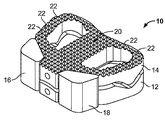
本願の例示的実施形態において、本願の椎間板インプラントは、固定インプラント装置又は人工椎間板装置として機能してもよい。開示されているインプラントは一般に、第一の内面と第一の外面を画定する第一の椎間要素と、第二の内面と第二の外面を画定する第二の椎間要素を含む。それぞれの椎間要素の第一の内面と第二の内面は通常、関節面形状を画定する構造的特徴物を含む。関節面形状は、第一と第二の椎間要素間の相対的運動を許容でき、例えば、このような関節面形状は、少なくとも部分的に、内外側及び前後側形状が同じでないことによって特徴付けられる。第一と第二の椎間要素の内外側及び前後側形状の少なくとも一方は、少なくとも1つの方向には実質的に同じであってもよい。これに加えて、第一と第二の椎間要素は、軸回転と前後運動に抵抗するが、これを阻止しない、1つ又は複数の特徴物を含んでいてもよい。 In an exemplary embodiment of the present application, the present disc implant may function as a fixed implant device or an artificial disc device. The disclosed implants generally include a first intervertebral element that defines a first inner surface and a first outer surface, and a second intervertebral element that defines a second inner surface and a second outer surface. The first and second inner surfaces of each intervertebral element typically include structural features that define an articular surface shape. The articular surface shape can allow relative movement between the first and second intervertebral elements, for example, such an articular surface shape is characterized by at least partially inconsistent inner and outer and front and rear shapes Attached. At least one of the medial and lateral and anteroposterior shapes of the first and second intervertebral elements may be substantially the same in at least one direction. In addition, the first and second intervertebral elements may include one or more features that resist, but do not prevent, axial rotation and back and forth movement.
開示されているインプラントの第一と第二の椎間要素はまた、側屈を制限する1つ又は複数の構造的特徴物も含んでいてよい。 The first and second intervertebral elements of the disclosed implant may also include one or more structural features that limit lateral bending.
第一と第二の椎間要素のうちの少なくとも一方と関連付けられる、少なくとも1つの固定ブロックが提供されてもよい。固定ブロックは、第一及び/又は第二の椎間要素に関して取り付けられてもよい。固定ブロックは一般に、第一と第二の椎間要素の前方に位置付けられる。これに加えて、固定ブロックは一般に、本体と、第一と第二の椎間要素のうちの一方に形成された穴に関して取り付けられるようになされたコネクターステムと、を含む。 At least one fixation block associated with at least one of the first and second intervertebral elements may be provided. The fixation block may be attached with respect to the first and / or second intervertebral element. The fixation block is generally positioned in front of the first and second intervertebral elements. In addition, the fixation block typically includes a body and a connector stem adapted to be attached with respect to a hole formed in one of the first and second intervertebral elements.
本願による例示的な椎間板インプラントは、第一と第二の椎間要素を含み、その各々が中央領域と、中央領域に関して第一の方向へと横に延びる第一のウィングと、中央領域に関して第二の方向へと横に延びる第二のウィングと、を画定する。第一の椎間要素の中央領域と第二の椎間要素の中央領域は一般に、接触関係に設置されるようになされており、このような中央領域の接触係合は、少なくとも部分的に、その関節面形状を確立する。 An exemplary disc implant according to the present application includes first and second intervertebral elements, each of which has a central region, a first wing extending transversely in a first direction with respect to the central region, and a first with respect to the central region. A second wing extending laterally in two directions. The central region of the first intervertebral element and the central region of the second intervertebral element are generally adapted to be placed in contact relationship, and the contact engagement of such central region is at least in part, Establish its joint surface shape.
第一と第二の椎間要素のそれぞれのウィングに、協働構造が通常、画定される。協働構造は、有利な点として、第一と第二の椎間要素間の相対的運動を許容できる。本願の例示的埋植では、協働構造は直立突起と溝を含む。協働的な直立突起と溝の各々が通常、前方ギャップ、後方ギャップ、遠位ギャップを画定する。 A cooperating structure is typically defined in each wing of the first and second intervertebral elements. The cooperating structure can advantageously allow relative movement between the first and second intervertebral elements. In the exemplary implant of the present application, the cooperating structure includes upstanding protrusions and grooves. Each of the cooperating upright projections and grooves typically defines an anterior gap, a posterior gap, and a distal gap.
第一と第二の椎間要素のウィングは、骨新生を許容する開口部を画定してもよい。それゆえ、第一と第二の椎間要素は、当初の埋植時には相互に関して可動的に連結されてもよく、埋植後、ある期間が経過した後に相互に関して固定され、又は癒合してもよい。固定又は癒合は一般に、例えば第一と第二の椎間要素に、及び/又は第一と第二の椎間要素の前方に形成された開口部を通じた骨新生によって実現する。これに加えて、第一及び/又は第二の椎間要素の外面は、隣接する解剖学的構造に関する固定を促進する表面特徴物、例えば棘状突起、錐体要素、コーティング及びこれらの組合せを含んでいてもよい。第一と第二の椎間要素はまた、その縁辺に沿って、前方に面する複数の開口部を含んでいてもよく、このような複数の開口部は、(i)固定ブロックの取付と、(ii)その臨床的設置のための器具との相互連結のうちの少なくとも一方を許容するように機能する。 The wings of the first and second intervertebral elements may define an opening that allows osteogenesis. Therefore, the first and second intervertebral elements may be movably connected with respect to each other at the time of initial implantation, and may be fixed or fused with respect to each other after a period of time after implantation. Good. Fixation or fusion is generally accomplished, for example, by osteogenesis through an opening formed in the first and second intervertebral elements and / or in front of the first and second intervertebral elements. In addition, the outer surfaces of the first and / or second intervertebral elements may include surface features that facilitate fixation with respect to adjacent anatomical structures, such as spinous processes, cone elements, coatings, and combinations thereof. May be included. The first and second intervertebral elements may also include a plurality of front-facing openings along their edges, such that the plurality of openings includes: (i) attachment of the fixation block; Ii) function to allow at least one of the interconnections with the instrument for its clinical installation.
第一と第二の椎間要素は一般に、埋植後に自動的に位置変更可能な回転中心を画定するように、可動的に連結される。例示的実施形態において、2つの椎間要素間の接触点又は接触領域は、前後方向と内外方向の両方及び、要素の曲率によれば上下方向へのシフトを含む区域又は領域内で自動的に位置変更可能であってもよい。また、当然のことながら、接触点/領域の移動と2つの椎間要素の相対的位置と向きによって、2つの構成要素の回転中心もまた、三次元的に(前後、内外、上下に)移動する。 The first and second intervertebral elements are generally movably coupled to define a center of rotation that can be automatically repositioned after implantation. In an exemplary embodiment, the contact point or contact area between two intervertebral elements is automatically within an area or region that includes both anterior and posterior and inward and outward directions and up and down shifts according to the curvature of the elements. The position may be changeable. Of course, depending on the movement of the contact point / region and the relative position and orientation of the two intervertebral elements, the center of rotation of the two components also moves three-dimensionally (back and forth, inside and outside, up and down). To do.
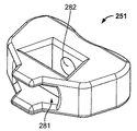
本願は更に、(i)シャフトと、(ii)シャフトに設置される操作具と、(iii)操作具がその中に設置される空洞を画定する試行用インプラントと、を含む手術器具を提供する。試行用インプラントは一般に、椎間腔に適合するような構成と寸法である。これに加えて、操作具は通常、2つの隣接する骨構造に窩洞を形成するようになされている。操作具はまた一般に、少なくとも2つの位置間で移動されるようになされており、このような位置のうちの少なくとも一方では、操作具の少なくとも一部が試行用インプラントから外側に延びる。試行用インプラントは、その第一と第二の面に開口部が画定されていてもよく、操作具は、少なくとも部分的に、第一と第二の開口部を通って延びる動作位置へと移動するようになされていてもよい。突起がシャフトの遠位端に画定されてもよく、これと協働する穴が、突起を受けるために試行用インプラントに画定されてもよい。 The present application further provides a surgical instrument comprising: (i) a shaft; (ii) a manipulator installed on the shaft; and (iii) a trial implant defining a cavity in which the manipulator is installed. . Trial implants are generally configured and dimensioned to fit into the intervertebral space. In addition to this, the operating tool is usually adapted to form a cavity in two adjacent bone structures. The manipulator is also generally adapted to be moved between at least two positions, at least one of the manipulators extending outward from the trial implant in at least one of such positions. The trial implant may have openings defined in the first and second sides thereof, and the manipulator is moved at least partially into an operating position extending through the first and second openings. You may be made to do. A protrusion may be defined at the distal end of the shaft, and a hole cooperating therewith may be defined in the trial implant to receive the protrusion.
本願は更に、インプラントの前方運動を防止するために、骨構造内に画定される窩洞と協働する隆起特徴物を画定する脊椎インプラントを提供する。 The present application further provides a spinal implant that defines raised features that cooperate with a cavity defined in the bone structure to prevent anterior movement of the implant.
本願と関連する例示的な方法において、この方法は、
椎間腔に手術器具の動作部を設置するステップであって、この手術器具が長いシャフトと少なくとも1つの骨切削要素を含むようなステップと、
骨切削器具のシャフトを回転させて、骨の終板に窩洞を形成するように少なくとも1つの骨切削要素を作動させるステップと、
手術器具の動作部を椎間腔から取り外すステップと、
少なくとも1つの骨切削要素により形成された窩洞と嵌合する隆起特徴物を有するインプラントを挿入するステップと、
を含む。
In an exemplary method associated with this application, the method comprises:
Placing a working portion of a surgical instrument in an intervertebral space, the surgical instrument including a long shaft and at least one bone cutting element;
Rotating the shaft of the bone cutting instrument to actuate at least one bone cutting element to form a cavity in the end plate of the bone;
Removing the operating part of the surgical instrument from the intervertebral space;
Inserting an implant having a raised feature that mates with a cavity formed by at least one bone cutting element;
including.
これに加えて、開示されている方法は、(i)手術器具の動作部を、少なくとも1つの骨切削要素が閉鎖又は保護位置にある状態で椎間腔の中に設置するステップと、(ii)椎間腔内で、少なくとも1つの骨切削要素を閉鎖又は保護位置から開放又は動作位置に移動させるステップと、を含んでいてもよい。骨切削器具の骨切削要素は、椎間腔内で、試行用インプラントの両面において動作するようになされていてもよい。椎骨終板から採取された骨材料を回収し、生検等の分析目的のため、及び/又は骨移植手術を容易にするために使用できる。本願の例示的実施形態において、採取された骨、例えばインプラント挿入のための所望の窩洞を形成する際に生成された骨切削片を捕集し、保持するための器具及び/又は器具付属品が提供されてもよい。 In addition, the disclosed method comprises the steps of (i) placing a working portion of a surgical instrument in an intervertebral space with at least one bone cutting element in a closed or protected position; ) Moving at least one bone cutting element from a closed or protected position to an open or operating position within the intervertebral space. The bone cutting element of the bone cutting instrument may be adapted to operate on both sides of the trial implant within the intervertebral space. Bone material collected from the vertebral endplate can be collected and used for analytical purposes such as biopsy and / or to facilitate bone grafting procedures. In an exemplary embodiment of the present application, there is an instrument and / or instrument accessory for collecting and retaining harvested bone, eg, bone cuttings generated in forming a desired cavity for implant insertion. May be provided.
開示されている椎間板インプラントのその他の特徴、機能、利点は、特に添付の図面に関連付けて読んだ場合に以下の説明から明らかとなるであろう。 Other features, functions, and advantages of the disclosed disc implants will become apparent from the following description, particularly when read in conjunction with the accompanying drawings.
当業者による本願の椎間板インプラントの作製と使用を支援するために、以下のような添付の図面を参照する。 To assist those skilled in the art in making and using the present disc implants, reference is made to the accompanying drawings as follows.
本願は、脊椎治療、例えば頸椎、胸椎及び/又は腰椎治療に使用される椎間板インプラントに関する。開示されている椎間板インプラントは、有利な点として、脊椎を安定化させ、関連する脊椎の問題に対処することができる。開示されている椎間板インプラントは、隣接椎体との癒合を刺激し、開示されている椎間板インプラントの設計と動作に基づき、時間の経過に伴って椎間板インプラントが生理学的位置に固定されるのを助長する。それゆえ、本願の例示的実施形態において、椎間板インプラントは、腰椎、胸椎及び/又は頸椎領域に挿入するために使用できる。 The present application relates to an intervertebral disc implant for use in spinal therapy, eg, cervical, thoracic and / or lumbar spinal therapy. The disclosed disc implants can advantageously stabilize the spine and address related spinal problems. The disclosed disc implant stimulates fusion with adjacent vertebral bodies and helps to secure the disc implant in a physiological position over time based on the design and operation of the disclosed disc implant To do. Therefore, in the exemplary embodiment of the present application, the intervertebral disc implant can be used for insertion into the lumbar, thoracic and / or cervical regions.
1.椎間板インプラント
本願による例示的な椎間板インプラントは、椎体間に臨床的に挿入されるようになされている。インプラントは一般に2つの要素を含み、これらが一体に連結されて椎間板インプラントを形成する。インプラントの、立位の個人に設置された状態で見た場合の上面と下面は、第一と第二の外側癒合面と呼ばれる。2の要素の対向面は内部連結面と呼ばれ、有利な点として、開示されている脊椎インプラントの当初埋植時に要素を相互に関して可動的に連結するように機能する特徴物/協働機構を含む。それゆえ、連結手段/機構は、第一と第二の椎間要素を相互に関して接続し、及び/又は整合させる機能を果たす。椎間要素の連結は、即ち、骨新生に基づいて第一と第二の椎間要素が相互に関して固定される前に、前記第一と第二の椎間要素の相互に関する運動を調整する。それゆえ、前記2つの椎間要素の連結により、要素が相互に関して固定的に位置づけることはない。本願によれば、前記要素が連結されても、一般に要素は相互に関して少なくとも1つの方向にわずかに移動できる。
1. Intervertebral disc implant An exemplary intervertebral disc implant according to the present application is adapted for clinical insertion between vertebral bodies. An implant generally includes two elements that are joined together to form a disc implant. The top and bottom surfaces of the implant as viewed in a standing individual are called the first and second outer healing surfaces. The opposing surfaces of the two elements are referred to as internal connection surfaces, and advantageously include features / cooperative mechanisms that function to movably connect the elements relative to each other upon initial implantation of the disclosed spinal implant. Including. Thus, the connecting means / mechanism serves to connect and / or align the first and second intervertebral elements with respect to each other. The connection of the intervertebral elements adjusts the movement of the first and second intervertebral elements relative to each other, i.e., before the first and second intervertebral elements are fixed relative to each other based on bone formation. Therefore, the connection of the two intervertebral elements does not place the elements fixed relative to each other. According to the present application, even if the elements are connected, generally the elements can move slightly in at least one direction relative to each other.
有利な点として、第三の要素を本明細書に記載されている第一と第二の要素間に設置してもよい。それゆえ、例えば非金属の構成要素を第一と第二の要素間に設置して、その接触領域間に設置されるようにしてもよい。非金属の構成要素はポリマー材料、例えばポリエチレン、ポリエーテルケトンケトン(polyether ketone ketone:PEKK)、及び/又はポリエーテルエーテルケトン(polyether ether ketone:PEEK)から作製してもよい。非金属の構成要素は、シート、比較的薄いブロック又は表面処理の形態をとることができ、有利な点として、金属−金属接触を防止するように機能し、その結果、金属疲労の可能性を低減させる。実際、開示されているポリマー材料のシート及び/又はブロックは、in situで第一と第二の要素間に挿入された時に楔様の構造として機能してもよい。例示的実施形態において、開示されているポリマー材料は、開示されている椎間要素の第一及び/又は第二の要素の「雄」部分に設置し、及び/又は塗布してもよい。 Advantageously, a third element may be placed between the first and second elements described herein. Thus, for example, a non-metallic component may be installed between the first and second elements and installed between the contact areas. Non-metallic components may be made from polymeric materials such as polyethylene, polyether ketone ketone (PEKK), and / or polyether ether ketone (PEEK). Non-metallic components can take the form of sheets, relatively thin blocks or surface treatments, and advantageously function to prevent metal-to-metal contact, thereby reducing the possibility of metal fatigue. Reduce. Indeed, the disclosed sheets and / or blocks of polymeric material may function as a wedge-like structure when inserted between the first and second elements in situ. In an exemplary embodiment, the disclosed polymeric material may be placed and / or applied to the “male” portion of the first and / or second element of the disclosed intervertebral element.
第一と第二の椎間要素の各々は挿入後、開示されている脊椎インプラントと隣接椎体との癒合が得られる/実現するまで、適当な手段、例えば1つ又は複数の有棘延長部によって隣接椎体に安定化させてもよい。それゆえ、インプラントと近隣/隣接骨との癒合/固定は、開示されている脊椎インプラントと従来の脊椎インプラントのどちらについても、椎間板インプラントの外面で起こる。 Each of the first and second intervertebral elements is inserted into a suitable means, such as one or more barbed extensions, until insertion / achievement of the disclosed spinal implant and adjacent vertebral body is achieved. To stabilize adjacent vertebral bodies. Therefore, the fusion / fixation of the implant with the adjacent / adjacent bone occurs on the outer surface of the disc implant for both the disclosed spinal implant and the conventional spinal implant.
本願の解釈において、「固定されたインプラント」とは、前記インプラントの椎間要素が相互に関して移動できないインプラントを表し、又は指し、即ち、第一と第二の椎間要素は、第一と第二の椎間要素間に存在する当初の可動的連結を無効にするような骨新生に基づいて、相互に関して実質的に固定される。これに対して、インプラントと隣接錐体との癒合は、椎間板インプラントの外面で起こる。 In the interpretation of this application, a “fixed implant” refers to or refers to an implant in which the intervertebral elements of the implant cannot move relative to each other, ie, the first and second intervertebral elements are first and second Are substantially fixed with respect to each other on the basis of osteogenesis that negates the initial movable connection between the intervertebral elements. In contrast, the fusion between the implant and the adjacent cone occurs on the outer surface of the disc implant.
本明細書中で後述するように、開示されている脊椎インプラントは、有利な点として、開示されている椎間板インプラントの構造的設計と動作に基づいて臨床的に実現される、第一と第二の椎間要素の相互に関する可動性という一時的な性質から恩恵を受ける。それゆえ、開示されているインプラントの第一と第二の椎間要素は、埋植後の最初の期間、例えば挿入後少なくとも1日は相対的に運動可能なままであり、その後、このような最初の期間が経過した後は、第一と第二の椎間要素は相互に関して実質的に固定され、その結果、開示されている脊椎インプラントは、挿入後、例えば12〜18カ月未満で固定されたインプラントへと変化する。 As will be described later herein, the disclosed spinal implants are advantageously implemented first and second based on the structural design and operation of the disclosed disc implants. Benefit from the temporary nature of intervertebral inter-element mobility. Therefore, the first and second intervertebral elements of the disclosed implant remain relatively moveable for an initial period after implantation, for example at least one day after insertion, after which After the first period has elapsed, the first and second intervertebral elements are substantially fixed with respect to each other so that the disclosed spinal implant is fixed, for example, in less than 12-18 months after insertion. Change to a new implant.
それゆえ、本願の例示的な椎間板インプラントは、第一の外側癒合面と第一の内側連結面を有する第一の椎間要素と、第二の外側癒合面と第二の内側連結面を有する第二の椎間要素と、第一と第二の椎間要素を相互に関して可動的に接続する連結手段/機構と、を含む。これに加えて、各椎間要素は一般に、時間の経過によって第一と第二の要素の相互に関する固定を可能にし/助長する骨性統合領域を含み、インプラントの第一と第二の要素は、挿入後、少なくとも1日は相対的に運動可能なままであり、インプラントは、臨床的に挿入/埋植された後12〜18カ月未満で固定されたインプラントに変化する。 Thus, the exemplary disc implant of the present application has a first intervertebral element having a first outer healing surface and a first inner coupling surface, and a second outer healing surface and a second inner coupling surface. A second intervertebral element and a coupling means / mechanism for movably connecting the first and second intervertebral elements with respect to each other. In addition, each intervertebral element generally includes a bone integration region that allows / facilitates the fixation of the first and second elements relative to each other over time, the first and second elements of the implant being Once inserted, the implant remains relatively moveable for at least one day and the implant changes to a fixed implant in less than 12-18 months after being clinically inserted / implanted.
添付の図面を参照しながら、本願の椎間板インプラントを以下により詳しく説明する。しかしながら、このような実施例を扱う前に、本願では、本明細書で開示する有利な椎間板インプラントに関連する形状、連結手段/機構、大きさ、材料、コーティング、コーティング剤、骨性統合領域/開口部、切開部/周方向差し込み領域、一時的可動性、治療方法について概説する。 The intervertebral disc implant of the present application will be described in more detail below with reference to the accompanying drawings. However, prior to dealing with such an embodiment, the present application will consider the shape, connection means / mechanism, size, material, coating, coating agent, osseous integration region / Outline of the opening, incision / circumferential insertion area, temporary mobility, and treatment method.
a.形状
本発明による椎間板インプラントは、一時的な安定化を可能にし、癒合と骨新生による長期的固定を刺激するどのような形状であってもよい。
a. Shape An intervertebral disc implant according to the present invention may be of any shape that allows temporary stabilization and stimulates long-term fixation by fusion and osteogenesis.
椎間板インプラントの形状は、上から見た場合に、丸形、円形、楕円形、扁円形又はソラマメ形の形状を有していてもよい。椎間板インプラントは、後方進入又は前方進入型の手術に使用するように設計されてもよいが、好ましくは、前方進入術用に設計され、その方が、術後の回復期間が短縮される可能性があるからである。或いは、開示されているインプラントは、経椎間孔腰椎椎体間固定又は側方進入腰椎椎体間固定用として設計されてもよい。 The shape of the intervertebral implant may have a round, circular, elliptical, oblate or broad bean shape when viewed from above. Intervertebral disc implants may be designed for use in posterior or anterior approach surgery, but are preferably designed for anterior approach, which may reduce the post-operative recovery period Because there is. Alternatively, the disclosed implants may be designed for transforaminal lumbar interbody fusion or lateral entry lumbar interbody fusion.
b.連結手段/機構
第一と第二の椎間要素の連結手段/機構は、例えば、埋植後の当初期間中に第一と第二の椎間要素が相互に関して若干移動できるようにするべきである。連結手段/機構は好ましくは、第一と第二の椎間要素の内側連結面に位置付けられる。椎間要素の内側連結面により形成される領域/空間は、インプラントの連結領域と呼んでもよい。椎間板インプラントの一時的可動性が得られるようにするために、第一と第二の椎間要素を連結しても、剛性のインプラントを形成しない。前述のように、非金属の構成要素、例えばポリマーシート、ブロック及び/又は表面処理を連結手段/機構間に設置してもよく、その結果、それらの間の金属−金属接触が制限される。本願で提出される図面に示されているように、内面の例示的な連結は、第一と第二の要素が少なくとも1つの方向に相互に関して移動する幾分かの余地を残す。
b. Connecting means / mechanism The connecting means / mechanism of the first and second intervertebral elements should, for example, allow the first and second intervertebral elements to move slightly relative to each other during the initial period after implantation. is there. The coupling means / mechanism is preferably located on the inner coupling surface of the first and second intervertebral elements. The area / space formed by the inner connecting surface of the intervertebral element may be referred to as the connecting area of the implant. Connecting the first and second intervertebral elements does not form a rigid implant in order to provide temporary mobility of the disc implant. As mentioned above, non-metallic components, such as polymer sheets, blocks and / or surface treatments may be placed between the coupling means / mechanisms, thereby limiting the metal-metal contact between them. As shown in the drawings filed in this application, the exemplary connection of the inner surface leaves some room for the first and second elements to move relative to each other in at least one direction.
c.大きさ
椎間板インプラントの円周は椎体の円周より小さくてもよい。具体的には、開示されている椎間板インプラントの形状は、椎体の基部がその前部においてインプラントに関して突出するように画定されてもよい。例えば、椎体は、インプラントに関して少なくとも0.2mm突出してもよく、また随意選択により、インプラントの縁辺を0.4mm又は0.6mmだけ超えてもよい。本願の他の例示的実施形態において、インプラントの外縁から椎体の縁辺までの距離は、この距離が5mm以上のオーダとなるように画定される。
c. Size The circumference of the intervertebral disc implant may be smaller than the circumference of the vertebral body. Specifically, the shape of the disclosed disc implant may be defined such that the base of the vertebral body protrudes with respect to the implant at its anterior portion. For example, the vertebral body may protrude at least 0.2 mm with respect to the implant and optionally exceed the margin of the implant by 0.4 mm or 0.6 mm. In another exemplary embodiment of the present application, the distance from the outer edge of the implant to the edge of the vertebral body is defined such that this distance is on the order of 5 mm or more.
このような寸法構成は、有利な点として、椎間板インプラントの側面における、又はこれに沿った骨新生の刺激を提供し、及び/又は可能にする可能性があり、椎間要素が隣接椎体に関して固定された後、骨組織は開示されている椎間要素の外縁において、又はこれに沿って結合する可能性があり、その結果、椎間要素は、埋植後ある期間で相互に関して更に固定される。 Such sizing may advantageously provide and / or enable osteogenic stimulation at or along the side of the disc implant, such that the intervertebral element is relative to the adjacent vertebral body. After being fixed, the bone tissue may join at or along the outer edge of the disclosed intervertebral element, so that the intervertebral elements are further fixed with respect to each other at some time after implantation. The
d.材料
本発明による椎間板インプラントは、埋植に適したどのような材料でも作製できる。それゆえ、開示されているインプラントは、セラミック、ポリマー、骨、金属の群から選択される1つ又は複数の材料で構成できるが、これらに限定されない。金属、ポリマー、セラミックが好ましい。材料は、インプラントへと加工する前及び/又は後に、ガラス状、ゴム状、半結晶、結晶の状態であってもよい。
d. Materials Intervertebral disc implants according to the present invention can be made of any material suitable for implantation. Thus, the disclosed implant can be composed of, but is not limited to, one or more materials selected from the group of ceramic, polymer, bone, metal. Metals, polymers and ceramics are preferred. The material may be in a glassy, rubbery, semi-crystalline, or crystalline state before and / or after processing into an implant.
本願の例示的実施形態において、開示されている脊椎インプラントは、ステンレス鋼、コバルトクロム、チタン(Ti)、チタン合金、例えばNiTiの形状記憶合金、タンタル(Ta)、ニオビウム(Nb)、ジルコニウム(Zr)、プラチナ(Pt)の群から選択された金属又は金属合金で構成できるが、これらに限定されない。好ましい金属と金属合金はチタン、タンタル、チタン合金、コバルトクロム及びその合金である。本願により使用される例示的なコバルトクロム材料は、CoCrMo合金を含む。本願により使用される例示的なチタン合金は、Ti6AI4Vを含む。本願により使用される例示的なステンレス鋼材料には、オーストナイト系ステンレス鋼、特に316及び316L型、Niフリーステンレス鋼が含まれる。 In exemplary embodiments of the present application, the disclosed spinal implants include stainless steel, cobalt chromium, titanium (Ti), titanium alloys such as NiTi shape memory alloys, tantalum (Ta), niobium (Nb), zirconium (Zr). ), A metal or metal alloy selected from the group of platinum (Pt), but is not limited thereto. Preferred metals and metal alloys are titanium, tantalum, titanium alloys, cobalt chrome and alloys thereof. Exemplary cobalt chromium materials used in accordance with the present application include CoCrMo alloys. An exemplary titanium alloy used by the present application includes Ti6AI4V. Exemplary stainless steel materials used in accordance with the present application include austenitic stainless steel, particularly types 316 and 316L, Ni-free stainless steel.
遷移金属等の金属を使って、本願の椎間板インプラントを作製してもよい。例えば、耐食性材料であるタンタル(Ta)を使用してもよい。実際、タンタルは本願によるインプラントの作製に有益でありえ、これは、それが一般に体液の作用による影響を受けず、刺激性を与えないからである。チタンは2つ目の耐食性遷移金属であり、高い硬度を有し、生理的に不活性であり、その結果、本願によるその有益性が高まる。チタンとタンタルは、比類のない骨性統合能力を有する。更に、これらの金属から作製される椎間板インプラントの解剖学的位置は、従来の撮像方法によって容易に分析できる。 The disc implant of the present application may be made using a metal such as a transition metal. For example, tantalum (Ta), which is a corrosion resistant material, may be used. In fact, tantalum can be beneficial in making implants according to the present application because it is generally unaffected by the action of body fluids and does not irritate. Titanium is the second corrosion-resistant transition metal, has high hardness and is physiologically inert, which increases its benefit according to the present application. Titanium and tantalum have unmatched bone integration capabilities. Furthermore, the anatomical position of disc implants made from these metals can be easily analyzed by conventional imaging methods.
本願により使用される例示的なセラミック材料は、生体不活性セラミック(アルミニウム(Al2O3)、部分安定化ジルコニア(ZrO2)、窒化珪素(Si3N4)、生体活性セラミック(水酸燐灰石(Ca10(PD4)6(OH)2)、バイオガラス)及び吸収性セラミック(例えば、燐酸三カルシウム、Ca3(PO4)2)を含むが、これらに限定されない。燐灰石とは燐酸塩鉱物の群を指し、一般に水酸燐灰石、フッ素燐灰石、塩素燐灰石と呼ばれ、これらは結晶格子内のそれぞれOH−、F−、又はCl−イオンの濃度が高いためにこのように名付けられる。水酸燐灰石は歯のエナメル質の主成分と骨材料の大きな割合を占める成分である。水酸燐灰石は、天然発生の形態の燐酸カルシウムであり、化学式はCa5(PO4)3(OH)であるが、一般には、結晶単位格子が2つの分子を含むことを示すためにCa10(PO4)6(OH)2と表記される。水酸燐灰石は、受容者によって受け入れられやすく、骨新生の実質的な刺激となる。 Exemplary ceramic materials used by the present application are bioinert ceramics (aluminum (Al 2 O 3 ), partially stabilized zirconia (ZrO 2 ), silicon nitride (Si 3 N 4 ), bioactive ceramics (hydroxyapatite hydroxide) (Ca 10 (PD 4 ) 6 (OH) 2 ), bioglass) and absorbent ceramics (eg, tricalcium phosphate, Ca 3 (PO 4 ) 2 ), including but not limited to apatite. Refers to a group of minerals, commonly referred to as hydroxyapatite, fluorapatite, and chlorapatite, which are so named because of the high concentration of OH-, F-, or Cl- ions in the crystal lattice, respectively. Apatite is a major component of dental enamel and bone material, and hydroxyapatite is a naturally occurring form of calcium phosphate that has the chemical formula Ca 5 but (PO 4) is 3 (OH), generally denoted as Ca 10 (PO 4) 6 ( OH) 2 in order to indicate that the crystal unit cell comprises two molecules. Hydroxyapatite Is readily accepted by the recipient and is a substantial stimulus for bone formation.
燐酸カルシウムセラミックのほとんどが結晶質である。結晶が高温で熱処理され、焼結されて、バイオセラミック材料が生成される。化学的には、これらは水酸燐灰石、燐酸三カルシウム、又はこれら2つの混合物である。これらは一般に粉末、粒状、又は多孔質、又は無孔質ブロックとして供給される。 Most of the calcium phosphate ceramics are crystalline. The crystals are heat treated at high temperatures and sintered to produce a bioceramic material. Chemically, these are apatite hydroxide, tricalcium phosphate, or a mixture of the two. They are generally supplied as powders, granules, or porous or nonporous blocks.
燐酸三カルシウムは水酸燐灰石より多孔質であり、10〜20倍の速度で生分解される。焼結温度もまた、完成品の挙動に影響を与える。燐酸三カルシウムは、製造条件に応じて、数カ月以内に完全に吸収されるか、数年かかって生体吸収される。体内で、これは部分的に、より生分解に時間がかかる水酸燐灰石に変換される。本願の例示的実施形態では、吸収性セラミック粒や吸収性燐酸三カルシウム(TCP)セラミック粒等の人工骨材料が使用される。 Tricalcium phosphate is more porous than hydroxyapatite and biodegrades 10-20 times faster. Sintering temperature also affects the behavior of the finished product. Depending on the production conditions, tricalcium phosphate is either completely absorbed within a few months or bioabsorbed over several years. In the body, this is partly converted to hydroxyapatite, which is more biodegradable. In exemplary embodiments of the present application, artificial bone materials such as resorbable ceramic grains and resorbable tricalcium phosphate (TCP) ceramic grains are used.
開示されている脊椎インプラントは更に、全体的又は部分的に、ガラスと熱分解カーボンで作製されてもよく、これは骨癒合刺激の点で効率が高い。 The disclosed spinal implants may also be made, in whole or in part, of glass and pyrolytic carbon, which is highly efficient in terms of bone healing stimuli.
本願による脊椎インプラントの作製に全体的又は部分的に使用される例示的なポリマーは、ポリラクチド(PLA)、ポリグリコリド(PGA)、ポリアンヒドリド、ポリオルトエステル、ポリ(D,L−乳酸)、ポリ(ラクチド−コ−グリコリド)(PLGA)、ポリ−D,L−乳酸−ポリ(エチレングリコール)、ポリ燐酸塩、ポリ(2−ヒドロキシエチルメタクリレート)、ポリ(N−ビニルピロリドン)、ポリ(メチルメタクリレート)、ポリ(ビニルアルコール)、ポリ(アクリル酸)、ポリアクリルアミド、ポリ(エチレン−コ−ビニルアセテート)、ポリ(メタクリル酸)、超高分子量ポリエチレン(ultra high molecular weight polyethylene:UHMWPE)、ポリエーテルエーテルケトン(PEEK)、ポリエーテルケトンケトン(PEKK)の群から選択されるが、これらに限定されない。本願による好ましいポリマーは、PEEKとPEKKを含む。例示的実施形態によれば、ポリマー要素(例えば、シート、ブロック及び/又は表面処理)は、本願による対向金属面間に配置されてもよい。 Exemplary polymers used in whole or in part to make spinal implants according to the present application are polylactide (PLA), polyglycolide (PGA), polyanhydride, polyorthoester, poly (D, L-lactic acid), poly (Lactide-co-glycolide) (PLGA), poly-D, L-lactic acid-poly (ethylene glycol), polyphosphate, poly (2-hydroxyethyl methacrylate), poly (N-vinylpyrrolidone), poly (methyl methacrylate) ), Poly (vinyl alcohol), poly (acrylic acid), polyacrylamide, poly (ethylene-co-vinyl acetate), poly (methacrylic acid), ultra high molecular weight polyethylene (UHMWPE), polyether ether Ketone (PEEK), is selected from the group of polyetherketoneketone (PEKK), but are not limited to. Preferred polymers according to the present application include PEEK and PEKK. According to exemplary embodiments, polymer elements (eg, sheets, blocks and / or surface treatments) may be disposed between opposing metal surfaces according to the present application.
本願による脊椎インプラントの作製に全体的又は部分的に使用される例示的な骨は、異種移植片、同種移植片、自家移植片の群から選択されてもよい。本願による好ましい骨は、異種移植片と同種移植片を含む。 Exemplary bones used in whole or in part to make spinal implants according to the present application may be selected from the group of xenografts, allografts, autografts. Preferred bone according to the present application includes xenografts and allografts.
開示されているインプラントは、1つ又は複数の適当な材料から作製してもよい。それゆえ、例示的実施形態において、開示されている脊椎インプラントは上記の材料の少なくとも1つからなる。別の実施形態において、開示されているインプラントは、少なくとも2種類の異なる材料からなる。いずれの材料も、インプラント全体の総量の1〜90パーセント等を構成してもよい。それゆえ、1つの材料はインプラント全体の総量の1〜10%、10〜20%、20〜30%、30〜40%、40〜50%、50〜60%、60〜70%、70〜80%又は80〜90%を占めてもよい。インプラントの要素は、金属の中心コアと、これを取り囲む1層の吸収性セラミック材料を含んでいてもよい。別の実施形態において、開示されているインプラントは、少なくとも3種類の異なる材料からなる。 The disclosed implants may be made from one or more suitable materials. Thus, in an exemplary embodiment, the disclosed spinal implant is comprised of at least one of the above materials. In another embodiment, the disclosed implant consists of at least two different materials. Any material may constitute 1 to 90 percent of the total amount of the entire implant, and the like. Therefore, one material is 1-10%, 10-20%, 20-30%, 30-40%, 40-50%, 50-60%, 60-70%, 70-80 of the total amount of the whole implant. % Or 80-90%. The elements of the implant may include a metal central core and a layer of absorbent ceramic material surrounding it. In another embodiment, the disclosed implant consists of at least three different materials.
椎間板インプラントの材料の弾性は好ましくは、骨の弾性と同等のオーダである。これに加えて、1つ又は複数の要素又は要素の一部を特定の材料の被覆層で覆うことによって、機能を最適化してもよい。 The elasticity of the material of the disc implant is preferably on the same order as the elasticity of the bone. In addition, the function may be optimized by covering one or more elements or parts of the elements with a covering layer of a specific material.
e.コーティング
インプラントのコーティングは、インプラントを埋植時及び埋植後の期間中に血液等の体液から保護するために行うことができる。コーティングは或いは、又はこれに加えて、適当な組成物を含めることによって、インプラントの近辺の骨成長を制御するために使用してもよい。
e. Coating Implant coating can be done to protect the implant from body fluids such as blood during and after implantation. The coating may alternatively or additionally be used to control bone growth in the vicinity of the implant by including a suitable composition.
例示的実施形態において、開示されているインプラントが被覆されるのは、外側癒合面、内側連結面又は要素の開口部の内面、又は各面もしくは面のあらゆる組合せの中のいずれの部分であってもよい。好ましい実施形態においては、開口部の内面が被覆される。 In an exemplary embodiment, the disclosed implant is coated on any portion of the outer healing surface, the inner connecting surface or the inner surface of the element opening, or any combination of each surface or surface. Also good. In a preferred embodiment, the inner surface of the opening is coated.
コーティングは一般に、少なくとも1層のコーティング材料を含む。コーティング材料は、どのような適当な材料から選択されてもよい。それゆえ、コーティングは、本明細書において後述するように、骨誘導及び/又は骨形成剤を含んでいてもよい。コーティングはまた、適当なポリマー材料、例えば、第一と第二の椎間要素の金属−金属接触を最小限にする材料の形態であってもよい。コーティングは更に、1つ又は複数の抗生剤を含んでいてもよい。 The coating generally comprises at least one layer of coating material. The coating material may be selected from any suitable material. Therefore, the coating may include an osteoinductive and / or osteogenic agent, as described later herein. The coating may also be in the form of a suitable polymeric material, such as a material that minimizes metal-metal contact of the first and second intervertebral elements. The coating may further comprise one or more antibiotics.
「被覆される」とは、コーティング材料が被覆面の外側にしかないかもしれないことも意味する。コーティングの厚さは一般に、コーティングの所望の機能と特性に基づいて選択され、厚さは1mm未満、0.5mm未満、又は0.25mm未満であってもよい。コーティングの厚さはまた、開示されているインプラントの表面に沿って、例えばインプラントの異なる表面地点において異なっていてもよい。開示されている椎間板インプラントのコーティングは、どのような適当なコーティング方法によって施されてもよく、例えば要素をコーティング材料の溶液に所定の時間だけ浸漬させる方法がある。コーティング材料はまた、インプラントに吹き付けてもよく、そのほか、前記コーティングを刷毛塗りによって塗布することもできる。 “Coated” also means that the coating material may only be outside the coated surface. The thickness of the coating is generally selected based on the desired function and properties of the coating, and the thickness may be less than 1 mm, less than 0.5 mm, or less than 0.25 mm. The thickness of the coating may also vary along the surface of the disclosed implant, for example at different surface points of the implant. The disclosed disc implant coating may be applied by any suitable coating method, for example by immersing the element in a solution of the coating material for a predetermined time. The coating material may also be sprayed onto the implant, or else the coating can be applied by brushing.
f.コーティング材料
本願の例示的実施形態において、1つ又は複数の保護コーティングを開示されている脊椎インプラントに設けてもよく、このような保護コーティングの材料は、ポリラクチド(PLA)、ポリグリコリド(PGA)、ポリアンヒドリド、ポリオルトエステル、ポリ(D,L−乳酸)、ポリ(ラクチド−コ−グリコリド)(PLGA)、ポリ−D,L−乳酸−ポリエチレングリコール、ポリ燐酸塩、ポリ(ラクチド−コ−グリコリド)とゼラチンスポンジの合成材料、ポリ(2−ヒドロキシエチルメタクリレート)、ポリ(N−ビニルピロリドン)、エチレンビニルアセテート(EVA)、ポリ(メチルメタクリレート)、ポリ(ビニルアルコール)、ポリ(アクリル酸)、ポリアクリルアミド、ポリ(エチレン−コ−ビニルアセテート)、ポリ(エチレングリコール)、ポリ(メタクリル酸)、L−PLAとポリカプロラクトン(PCL)のホモポリマー、ポリ(オルトエステル)、ポリ(無水物)、擬似ポリ(アミノ酸)の群から選択されるが、これらに限定されない。開示されているポリマー材料は、有利な点として、本願による第一と第二の椎間要素間の金属−金属接触を制限及び/又は排除することができる。
f. Coating Materials In exemplary embodiments of the present application, one or more protective coatings may be provided on the disclosed spinal implants, such as polylactide (PLA), polyglycolide (PGA), Polyanhydride, polyorthoester, poly (D, L-lactic acid), poly (lactide-co-glycolide) (PLGA), poly-D, L-lactic acid-polyethylene glycol, polyphosphate, poly (lactide-co-glycolide) ) And gelatin sponge synthetic material, poly (2-hydroxyethyl methacrylate), poly (N-vinylpyrrolidone), ethylene vinyl acetate (EVA), poly (methyl methacrylate), poly (vinyl alcohol), poly (acrylic acid), Polyacrylamide, poly (ethylene-co-vinyl Acetate), poly (ethylene glycol), poly (methacrylic acid), L-PLA and polycaprolactone (PCL) homopolymer, poly (orthoester), poly (anhydride), pseudo-poly (amino acid) However, it is not limited to these. The disclosed polymeric material can advantageously limit and / or eliminate metal-metal contact between the first and second intervertebral elements according to the present application.
別の例示的実施形態において、コーティングは、生理活性成分、例えば骨誘導及び/又は骨形成剤(水酸燐灰石及び/又は燐酸三カルシウム等)又は抗生剤を含んでいてもよい。例えば、コーティングに骨誘導及び/又は骨形成剤を含めることによって、早期の骨形成工程、例えば特定の細胞クラスの走化性を誘導でき、その一方で、抗生剤を含めることにより、細菌感染を軽減又は防止できる。 In another exemplary embodiment, the coating may include a bioactive component, such as an osteoinductive and / or osteogenic agent (such as apatite hydroxide and / or tricalcium phosphate) or an antibiotic. For example, the inclusion of osteoinductive and / or osteogenic agents in the coating can induce early osteogenic processes, such as chemotaxis of certain cell classes, while the inclusion of antibiotics can reduce bacterial infection. Can be reduced or prevented.
骨誘導及び/又は骨形成剤は、「成長因子」と呼ぶこともでき、及び/又はそれを含むことができ、一般に、細胞表面の受容体と結合する蛋白であり、主として、細胞移動、細胞増殖及び/又は分化を活発化させる。多くの骨誘導及び/又は骨形成剤は万能であり、様々な細胞種類の細胞分裂を刺激し、その一方で、ある細胞種類に特定のものもある。 Osteoinductive and / or osteogenic agents can also be referred to as and / or can include “growth factors” and are generally proteins that bind to cell surface receptors, mainly cell migration, cell Activate proliferation and / or differentiation. Many osteoinductive and / or osteogenic agents are versatile and stimulate cell division of various cell types, while others are specific to certain cell types.
骨誘導と考えられる物質は一般に、モルフォゲン、例えば骨形成蛋白を含んでいる。モルフォゲンは、未分裂の細胞を表現型的に変換するように刺激することによって、組織と臓器系の発育を開始させる。本願により使用可能な適当な成長因子は、成長及び分裂因子等の組織成長促進物質、例えば血小板由来成長因子(platelet−derived growth factor:PDGF)、形質転換成長因子(transforming growth factor:TGF)、酸性及び塩基性線維芽細胞成長因子(fibroblast growth factor:FGF)、インスリン様成長因子(insulin−like growth factor:IGF)、骨形成蛋白(bone morphogenetic proteins:BMP)及びこれらの組合せ等を含むが、これらに限定されない。 Substances believed to be osteoinductive generally include morphogens such as bone morphogenetic proteins. Morphogens initiate tissue and organ system development by stimulating phenotypic transformation of undivided cells. Suitable growth factors that can be used in accordance with the present application include tissue growth promoters such as growth and division factors such as platelet-derived growth factor (PDGF), transforming growth factor (TGF), acidic And basic fibroblast growth factor (FGF), insulin-like growth factor (IGF), bone morphogenetic protein (BMP), and combinations thereof. It is not limited to.
本願の例示的実施形態において、骨誘導及び/又は骨形成剤は、血小板由来成長因子(platelet−derived growth factor:PDGF)(PDGF−AA,−AB,−BB)、インスリン様成長因子I及びII(IGF−I、IGF−II)、繊維芽成長因子(FGF)(酸性FGF−aFGF、塩基性FGF−bFGF)、形質転換成長因子ベータ(TGF−B)(TGF−B(TGF−B 1、2、3、4、5))、骨誘導及び骨形成蛋白(BMP)(BMP−1、BMP−2、BMP−3、BMP−4、BMP−5、BMP−6、BMP−7、BMP−8、BMP−9、BMP−10、BMP−11、BMP−12)、表皮成長因子(epidermal growth factor:EGF)、セメント質由来成長因子(cementum−derived growth factor:CGF)、上皮小体ホルモン関連蛋白(PTHrP)の骨成長因子の群から選択されてもよい。好ましい成長因子又は骨誘導及び/又は骨形成剤は、骨形成蛋白(BMP−1、BMP−2、BMP−3、BMP−4、BMP−5、BMP−6、BMP−7、BMP−8、BMP−9、BMP−10、BMP−11、BMP−12)及び血小板由来成長因子(PDGF)(PDGF−AA、−AB、−BB)を含む。 In an exemplary embodiment of the present application, the osteoinductive and / or osteogenic agent is a platelet-derived growth factor (PDGF) (PDGF-AA, -AB, -BB), insulin-like growth factor I and II. (IGF-I, IGF-II), fibroblast growth factor (FGF) (acidic FGF-aFGF, basic FGF-bFGF), transforming growth factor beta (TGF-B) (TGF-B (TGF-B1, 2, 3, 4, 5)), bone induction and bone morphogenetic protein (BMP) (BMP-1, BMP-2, BMP-3, BMP-4, BMP-5, BMP-6, BMP-7, BMP- 8, BMP-9, BMP-10, BMP-11, BMP-12), epidermal growth factor (EGF), cement It may be selected from the group of quality-derived growth factor (CGF), parathyroid hormone-related protein (PTHrP) bone growth factor. Preferred growth factors or osteoinductive and / or osteogenic agents are bone morphogenetic proteins (BMP-1, BMP-2, BMP-3, BMP-4, BMP-5, BMP-6, BMP-7, BMP-8, BMP-9, BMP-10, BMP-11, BMP-12) and platelet derived growth factor (PDGF) (PDGF-AA, -AB, -BB).
本願によって使用されるコーティングは、少なくとも1種の骨誘導及び/又は骨形成剤と、随意選択により2種以上のそのような化学物質、例えば2種の化学物資、3種の化学物質、4種の化学物質、5種の化学物質、6種の化学物質、7種の化学物質、8種の化学物質、9種の化学物質、10種の化学物質、又はそれ以上を含んでいてもよい。本願の実施例は、1種、2種又は3種の骨誘導及び/又は骨形成剤を含む。より好ましい実施例は、1種又は2種の骨誘導及び/又は骨形成剤を含む。 The coating used by the present application comprises at least one osteoinductive and / or osteogenic agent and optionally two or more such chemicals, eg two chemicals, three chemicals, four 5 chemical substances, 6 chemical substances, 7 chemical substances, 8 chemical substances, 9 chemical substances, 10 chemical substances, or more. Examples of the present application include one, two or three osteoinductive and / or osteogenic agents. More preferred embodiments include one or two osteoinductive and / or osteogenic agents.
1つ又は複数の層のコーティング材料を開示されているインプラントに形成し、又は塗布してもよい。2層又はそれ以上の層が形成/塗布される実施例では、これらの層の組成は同じでも異なっていてもよく、1層又は複数の層は骨誘導及び/又は骨形成剤又はその他の生体活性成分を含んでいてもよい。 One or more layers of coating material may be formed or applied to the disclosed implants. In embodiments where two or more layers are formed / applied, the composition of these layers may be the same or different, and one or more layers may be osteoinductive and / or osteogenic agents or other living organisms. An active ingredient may be included.
或いは、骨誘導及び/又は骨形成剤は、開示されている椎間板インプラントの要素を形成する材料の1つ又は複数からなっていてもよい。それゆえ、インプラントは、骨誘導及び/又は骨形成剤の1種又は複数を分泌するように設計されてもよく、それによって骨成長の刺激が、椎間板インプラントの要素によって命令され、又はその他の方法で開始/支持される。開示されている椎間板インプラントは好ましくは、骨形成を促進する。 Alternatively, the osteoinductive and / or osteogenic agent may consist of one or more of the materials that form the elements of the disclosed disc implant. Thus, the implant may be designed to secrete one or more of osteoinductive and / or osteogenic agents so that stimulation of bone growth is commanded by elements of the disc implant or other method Initiated / supported by The disclosed disc implant preferably promotes bone formation.
g.骨性統合領域/開口部
開示されている椎間板インプラントの第一と第二の椎間要素は一般に、骨性統合領域を含む、及び/又は画定する。このような領域は一般に、骨成長を刺激し、命令する能力を有する。例えば、椎間要素は、このような椎間要素の外面の、近隣の脊椎要素に関して癒合するための骨成長を刺激するようになされていてもよい。開示されている椎間要素はまた一般に、時間の経過に伴って椎間要素が相互に関して固定されるように、骨新生を更に命令するようになされている。それゆえ、椎間板インプラントの第一と第二の椎間要素の一時的な可動性は、挿入/埋植後のある期間内に、第一と第二の椎間要素の固定に取って代わられる。それゆえ、骨性統合領域を含めることによって、時間の経過による第一と第二の椎間要素の相互に関する固定も可能となり、及び/又は促進される。
g. Bone Integration Zone / Aperture The first and second intervertebral elements of the disclosed disc implant generally include and / or define a bone integration zone. Such areas generally have the ability to stimulate and direct bone growth. For example, the intervertebral elements may be adapted to stimulate bone growth to coalesce with respect to neighboring spinal elements on the outer surface of such intervertebral elements. The disclosed intervertebral elements are also generally adapted to further direct osteogenesis so that the intervertebral elements are fixed relative to each other over time. Therefore, the temporary mobility of the first and second intervertebral elements of the disc implant is replaced by the fixation of the first and second intervertebral elements within a period after insertion / implantation. . Therefore, inclusion of the osseous integration region also allows and / or facilitates the fixation of the first and second intervertebral elements relative to each other over time.
第一と第二の椎間要素の内面と外面は、本願による骨新生を最適化するように設計された骨性統合領域を含み、及び/又は画定してもよい。本明細書において後述するように、骨性統合領域は、全体的又は部分的に、骨新生のための進入点となる、椎間要素の表面の穴及び/又は切開部等の開口部によって画定されてもよい。骨性統合領域はまた、適当な骨誘導及び/又は骨形成剤、及び/又は骨誘導及び/又は骨形成材料も含んでいてよい。椎間要素に形成された開口部に骨誘導及び/又は骨形成剤が含まれる本願の実施例、及び/又はそのような開口部内の骨誘導及び/又は骨形成材料は「充填」開口部と呼ばれる。 The inner and outer surfaces of the first and second intervertebral elements may include and / or define a bone integration region designed to optimize osteogenesis according to the present application. As will be described later in this specification, the osteogenic integrated region is defined, in whole or in part, by openings such as holes and / or incisions in the surface of the intervertebral element that serve as entry points for osteogenesis. May be. The osteogenic integrated region may also include a suitable osteoinductive and / or osteogenic agent, and / or osteoinductive and / or osteogenic material. Embodiments of the present application in which the opening formed in the intervertebral element includes an osteoinductive and / or osteogenic agent, and / or the osteoinductive and / or osteogenic material in such an opening is referred to as a “filled” opening. be called.
本願の例示的実施形態において、開示されている椎間要素は、骨新生に適した1つ又は複数の開口部を含むか、画定し、このような開口部は、(i)骨芽細胞と骨形成原細胞の進入を可能にし、(ii)このような骨芽細胞と骨形成原細胞の生存能力を維持するのに十分な大きさである。開口部は一般に、開示されている椎間要素の中へと進み、又は延び、要素の中への骨新生が可能となる。開口部は、椎間板インプラントの椎間要素の設計/形状に適合するどのような形状又は大きさであってもよい。例えば、開口部は、椎間要素を通って延びるまっすぐな(又は実質的にまっすぐな)通路を構成し、又は画定してもよい。例示的実施形態において、開口部の直径は、通路が椎間要素を通って延びる間に変化してもよく、例えば開放している通路の直径は、要素の内部空間とともに拡大してもよい。 In an exemplary embodiment of the present application, the disclosed intervertebral elements include or define one or more openings suitable for osteogenesis, such openings include (i) osteoblasts and It is large enough to allow the entry of osteogenic cells and (ii) maintain the viability of such osteoblasts and osteogenic cells. The opening generally advances or extends into the disclosed intervertebral element, allowing osteogenesis into the element. The opening may be any shape or size that matches the design / shape of the intervertebral element of the disc implant. For example, the opening may constitute or define a straight (or substantially straight) passage extending through the intervertebral element. In an exemplary embodiment, the diameter of the opening may vary while the passage extends through the intervertebral element, for example, the diameter of the open passage may increase with the interior space of the element.
開口部によって占められる椎間要素の表面積は一般に、時間の経過によって第一と第二の椎間要素が相互に関して固定されるための所望のレベルの骨新生を支持するのに十分である。しかしながら、留意される点として、このような骨新生は一般に、このような開口部を通じた骨成長に限定されず、椎間要素の外縁に沿って、又はその周囲に延びる骨新生によって補完される。本願の例示的実施形態において、開口部は、第一及び/又は第二の椎間要素の表面積の少なくとも5%を占め、別の例示的実施形態では、このような面の少なくとも10%又は少なくとも15%が、十分な骨新生を可能にし、/刺激するためである。別の例示的実施形態において、開口部/穴によって占められる第一及び/又は第二の椎間要素の表面積は、このような表面積の10〜40%、例えばその20〜35%である。開口部と内部空間の容量は、開示されている椎間板インプラントの椎間要素の嵩容量の10〜90%、例えば椎間要素の嵩容量の20〜80%、30〜70%、40〜60%及び/又は30〜60%を構成してもよい。 The surface area of the intervertebral element occupied by the opening is generally sufficient to support the desired level of osteogenesis for the first and second intervertebral elements to be fixed relative to each other over time. However, it should be noted that such osteogenesis is generally not limited to bone growth through such openings, but is complemented by osteogenesis extending along or around the outer edge of the intervertebral element. . In an exemplary embodiment of the present application, the opening occupies at least 5% of the surface area of the first and / or second intervertebral element, and in another exemplary embodiment, at least 10% or at least of such a surface. 15% to allow / stimulate sufficient osteogenesis. In another exemplary embodiment, the surface area of the first and / or second intervertebral element occupied by the opening / hole is 10-40% of such surface area, for example 20-35% thereof. The volume of the opening and interior space is 10-90% of the bulk volume of the intervertebral element of the disclosed disc implant, for example 20-80%, 30-70%, 40-60% of the bulk volume of the intervertebral element And / or 30-60%.
椎間要素の嵩容量について言及する場合、連結領域の容量は含まれず、個々の椎間要素の概算の容量にすぎず、開口部の容量と内部空間の容量があれば、これらを含む。 When referring to the bulk volume of the intervertebral element, the volume of the connecting region is not included, only an approximate volume of the individual intervertebral element, including the volume of the opening and the volume of the interior space, if any.
本願の例示的実施形態において、第一と第二の椎間要素の1つ又は複数の開口部は、椎間要素が連結手段/機構を介して相互に係合された時に、相互に対向し、即ち実質的に整合する。このような開口部を対向するように/整合させて配置することにより、本願の所望の目的を達成するため、例えば椎間板インプラントを各外面において隣接椎体に関して癒合させ、椎間要素の内面によって形成/画定される連結領域内に骨組織が形成された時に、椎間板インプラントの第一と第二の椎間要素が相互に関して固定されるようにするために、両方の椎間要素の中への骨新生を促進するのに最適な条件となる。 In an exemplary embodiment of the present application, the one or more openings in the first and second intervertebral elements are opposed to each other when the intervertebral elements are engaged with each other via a coupling means / mechanism. I.e. substantially matched. By placing such openings in opposition / alignment, for example, an intervertebral disc implant is fused with respect to adjacent vertebral bodies at each outer surface and formed by the inner surface of the intervertebral element. / Bone into both intervertebral elements to ensure that the first and second intervertebral elements of the disc implant are fixed relative to each other when bone tissue is formed in the defined connection area. It is the optimal condition for promoting newborn.
一方又は両方の椎間要素の表面上の小さな開口部は、「細孔」と呼んでもよく、これはインプラントが表面において骨成長を刺激する能力に影響を与える。インプラントの多孔性レベル、細孔の大きさの分布、細孔の形状、細孔の相互接続性は骨成長の程度に大きな影響を与える。骨誘導を促進する第一及び/又は第二の椎間体の外面上の例示的な細孔容積は、150〜500mm3である。これに加えて、一方又は両方の椎間要素の外面は更に、隣接椎体に関する癒合を更に促進するために、粗い、でこぼこ、又はざらざらであってもよい。 Small openings on the surface of one or both intervertebral elements may be referred to as “pores”, which affect the ability of the implant to stimulate bone growth at the surface. The porosity level of the implant, pore size distribution, pore shape, and pore interconnectivity have a significant effect on the extent of bone growth. An exemplary pore volume on the outer surface of the first and / or second intervertebral body that promotes osteoinduction is 150-500 mm 3 . In addition, the outer surface of one or both intervertebral elements may further be rough, bumpy, or rough to further promote fusion with adjacent vertebral bodies.
h.切開部/周方向差し込み領域
上述の開口部の代わりに、又はそれと共に、開示されている椎間要素は、骨新生と、時間の経過による第一と第二の椎間要素の固定を促進するための、様々な形/形状の切開部又は周方向差し込み領域を含み、又は画定してもよい。それゆえ、本願の例示的実施形態においては、椎間要素の、これを通る開口部を切開部/周方向差し込み領域と組み合わせることによって、所望の程度の骨新生を促進/助長してもよい。例えば、開示されている開口部及び切開部/周方向差し込み領域は、細胞が進入し、新たな骨を作るための足場を提供することによって、骨再生を刺激しうる。
h. Incision / circumferential insertion area In lieu of or in conjunction with the opening described above, the disclosed intervertebral elements facilitate bone formation and fixation of the first and second intervertebral elements over time. Various shapes / shapes of incisions or circumferential insertion regions may be included or defined. Thus, in the exemplary embodiment of the present application, the opening through the intervertebral element may be combined with the incision / circumferential insertion region to promote / encourage the desired degree of osteogenesis. For example, the disclosed openings and incision / circumferential insertion regions can stimulate bone regeneration by providing a scaffold for cells to enter and create new bone.
前述のように、開示されている椎間板インプラントの椎間要素は、1種又は複数の異なる材料から作製してもよい。本願の例示的実施形態において、充填物は椎間板インプラントの椎間要素の開口部及び/又は切開部/周方の差し込み領域の中に位置付けてもよく、その結果、充填されたインプラントが得られる。充填物は、骨形成活性及び/又は骨吸収阻害の命令及び/又は刺激に適した材料を含んでいてもよい。例えば、骨又は脱灰骨基質(DBM)の自家及び/又は同種移植片を充填材料として使用してもよい。人工骨材料、例えばセラミック材料もまた使用できる。吸収性材料、例えば吸収性セラミック粒も利用でき、これが適当な期間内での開口部及び/又は切開部/周方の差し込み領域内の骨形成を可能にし、及び/又は助長する。それゆえ、開示されている脊椎インプラントは、吸収性材料、例えば吸収性セラミック粒で充填されてもよく、これは適当なパッケージングによって骨新生のタイミング及び/又は程度に役立ちうる。別の例示的実施形態において、充填物は、コーティングに関して述べたように、骨誘導及び/又は骨形成剤を含んでいてもよい。 As described above, the intervertebral elements of the disclosed disc implants may be made from one or more different materials. In an exemplary embodiment of the present application, the filling may be located within the intervertebral element opening and / or incision / circumferential insertion region of the disc implant, resulting in a filled implant. The filling may comprise materials suitable for ordering and / or stimulating osteogenic activity and / or inhibition of bone resorption. For example, autologous and / or allograft of bone or demineralized bone matrix (DBM) may be used as the filling material. Artificial bone materials such as ceramic materials can also be used. Absorbable materials, such as absorbent ceramic grains, may also be utilized, which allow and / or facilitate bone formation in the opening and / or incision / circumferential insertion area within a reasonable period of time. Thus, the disclosed spinal implants may be filled with a resorbable material, such as resorbable ceramic grains, which can aid in the timing and / or extent of osteogenesis by appropriate packaging. In another exemplary embodiment, the filler may include an osteoinductive and / or osteogenic agent as described with respect to the coating.
i.一時的可動性
本願による椎間板インプラントは、有利な点として、周囲の椎体と椎骨と癒合する。具体的には、第一と第二の椎間要素の外側癒合面は、近隣の骨/椎体との癒合に適している。
i. Temporary mobility Intervertebral disc implants according to the present application advantageously fuse with the surrounding vertebral bodies and vertebrae. Specifically, the outer union surface of the first and second intervertebral elements is suitable for union with neighboring bone / vertebral bodies.
隣接骨/椎体に関する上記の癒合とは別に、開示されている第一と第二の椎間要素の特徴と配置により、有利な点として、埋植後にはこれらの要素は相互に関して一時的に運動可能となる。しかしながら、開示されている椎間板インプラントの要素は、骨再生を刺激するように、即ちインプラントの椎間要素の中へと骨成長を導くように構成される。この骨新生は、時間の経過に伴って第一と第二の椎間要素が相互に関して固定され、その結果、椎間板インプラントの第一と第二の椎間要素の一時的可動性に取って代わる/これを無効にすることにつながる。 Apart from the fusion described above with respect to the adjacent bone / vertebral body, the disclosed features and arrangements of the first and second intervertebral elements have the advantage that after implantation these elements are temporarily It becomes possible to exercise. However, the disclosed disc implant elements are configured to stimulate bone regeneration, that is, to direct bone growth into the implant's intervertebral elements. This osteogenesis is that the first and second intervertebral elements are fixed relative to each other over time, thus replacing the temporary mobility of the first and second intervertebral elements of the disc implant. / This leads to invalidation.
第一と第二の椎間要素の一時的可動性は、有利な点として、生理学的に容認可能な位置での椎間板インプラントの固定によって取って代わられ/無効とされる。このような、開示されているインプラントの生理学的に容認可能な位置は、埋植時点ではなく、挿入/埋植後数日から数週間で実現される。より詳しくは、インプラントの第一と第二の椎間要素の相対的位置は、それらの間の運動可能な連結に基づき、受容者の負荷、姿勢、脊椎運動によって影響を受ける、及び/又はそれに反応する位置に適応される。それゆえ、第一と第二の椎間要素の相互に関する固定は、インプラントの中及び/又はその周囲の骨新生により、埋植後、ある期間かかって起こる。インプラントの挿入/埋植に関連する外科手術中に判断される固定位置を確立するのではなく、開示されているインプラントが自然に、各患者に合わせて固定されることは、非常に有利である。 The temporary mobility of the first and second intervertebral elements is advantageously replaced / defeated by fixation of the disc implant in a physiologically acceptable position. Such a physiologically acceptable position of the disclosed implant is achieved in days to weeks after insertion / implantation, not at the time of implantation. More particularly, the relative position of the first and second intervertebral elements of the implant is influenced by and / or affected by the recipient's load, posture, spinal motion based on the movable connection between them. Adapted to the position to react. Therefore, the fixation of the first and second intervertebral elements relative to each other takes place over a period of time after implantation due to bone formation in and / or around the implant. Rather than establishing a fixed position determined during surgery associated with implant insertion / implantation, it is highly advantageous that the disclosed implants are naturally fixed to each patient. .
本願のある例示的実施形態において、固定されたインプラントの形成につながる、第一と第二の椎間要素の相互に関する固定を引き起こすのは、主として椎間板インプラントの椎間要素の骨性統合領域で起こる骨新生である。 In certain exemplary embodiments of the present application, it is primarily in the osseointegration region of the intervertebral element of the intervertebral disc implant that causes fixation of the first and second intervertebral elements relative to each other, leading to the formation of a fixed implant. Osteogenesis.
本願の例示的実施形態において、椎間板インプラントの第一と第二の椎間要素は、埋植後のある期間、例えば8時間より長時間、16時間より長時間、及び/又は24時間より長時間にわたって相対的に運動可能なままである。別の例示的実施形態において、椎間板インプラントの第一と第二の椎間要素は、埋植後の、少なくとも1日、少なくとも2日、少なくとも3日、及び/又は4又は5日より長期の期間にわたって相対的に運動可能なままである。本願の実施形態において、椎間板インプラントの第一と第二の椎間要素は、挿入後、即ち埋植後1〜90日間、3〜30日間、及び/又は20〜25日間にわたり可動性を保つ。 In exemplary embodiments of the present application, the first and second intervertebral elements of the intervertebral disc implant may have a period of time after implantation, such as longer than 8 hours, longer than 16 hours, and / or longer than 24 hours. Remains relatively movable. In another exemplary embodiment, the first and second intervertebral elements of the intervertebral disc implant have a period of at least 1 day, at least 2 days, at least 3 days, and / or longer than 4 or 5 days after implantation. Remains relatively movable. In embodiments of the present application, the first and second intervertebral elements of the disc implant remain mobile after insertion, i.e., 1-90 days, 3-30 days, and / or 20-25 days after implantation.
本願の別の例示的実施形態において、開示されている椎間板インプラントは、挿入/埋植後18カ月未満、又は12カ月未満、又は8カ月未満、又は6カ月未満で、固定されたインプラントに変化し、この場合、椎間板インプラントの第一と第二の椎間要素の相対的可動性は、相互に関して固定される。例示的実施形態において、開示されている椎間要素は、挿入/埋植後3〜12カ月以内、5〜10カ月以内、及び/又は6〜9カ月以内で相互に関して固定される。 In another exemplary embodiment of the present application, the disclosed disc implant changes to a fixed implant in less than 18 months, or less than 12 months, or less than 8 months, or less than 6 months after insertion / implantation. In this case, the relative mobility of the first and second intervertebral elements of the disc implant is fixed with respect to each other. In exemplary embodiments, the disclosed intervertebral elements are fixed relative to each other within 3-12 months, within 5-10 months, and / or within 6-9 months after insertion / implantation.
開示されている椎間板インプラントの固定は、進行する骨新生に基づく漸進的なプロセスであるため、固定又は可動性の程度を埋植後に評価できる。更に、固定のプロセスは異なる対象物の異なる動力学で発生する。例示的実施例において、開示されている椎間板インプラントは、埋植直後の数週間で少なくとも65%固定され、又は埋植直後の数週間で少なくとも70%固定され、又は埋植直後の数週間で少なくとも75%固定され、又は埋植直後の数週間で少なくとも80%固定され、埋植直後の数週間で少なくとも85%固定されると予想できる。例示的実施形態において、開示されている椎間板インプラントは、埋植後1カ月で少なくとも90%固定され、又は埋植後1カ月で少なくとも92%固定され、埋植後1カ月で少なくとも95%固定される。最終的に、開示されている椎間板インプラントは100%固定される。 Since the disclosed fixation of an intervertebral disc implant is a gradual process based on progressive osteogenesis, the degree of fixation or mobility can be assessed after implantation. Furthermore, the fixation process occurs with different dynamics of different objects. In exemplary embodiments, the disclosed disc implant is at least 65% fixed in the weeks immediately after implantation, or at least 70% fixed in the weeks immediately after implantation, or at least in the weeks immediately after implantation. It can be expected to be 75% fixed or at least 80% fixed in the weeks immediately after implantation and at least 85% fixed in the weeks immediately after implantation. In an exemplary embodiment, the disclosed disc implant is at least 90% fixed at 1 month after implantation, or at least 92% fixed at 1 month after implantation, and at least 95% fixed at 1 month after implantation. The Finally, the disclosed disc implant is 100% fixed.
j.治療方法
脊椎損傷又はその他の疾患による腰痛及び/又は下肢痛を有する患者においては、椎間板インプラントの挿入によって痛みが緩和する可能性がある。本願のある態様は、それを必要とする個人の治療方法に関し、この方法は、椎間板インプラントの挿入を含み、このような椎間板インプラントは、埋植後ある期間中、例えば挿入/埋植後少なくとも1日は相対的に運動可能なままである第一と第二の椎間要素を含み、インプラントは挿入後ある期間、例えば18カ月未満で固定インプラントに変化する。開示されている方法は、前方、側方、後方進入及び/又は経椎間孔固定術により行われてもよい。これに加えて、開示されている方法は、挿入/埋植(又はそれ以前からの)後方安定化手段/器具と組み合わせてもよい。後方安定化は、柔軟(ダイナミック)、半剛性又は剛性インプラント、例えば弓根スクリュー、棘突起間スペーサ又は椎間関節スクリュー又は、当業界で公知であるか、今後開発されるその他の固定/安定化方式の形をとることができる。
j. Treatment Methods In patients with low back pain and / or lower limb pain due to spinal cord injury or other diseases, insertion of an intervertebral disc implant may alleviate the pain. An aspect of the present application relates to a method for treating an individual in need thereof, the method comprising the insertion of a disc implant, wherein such a disc implant is for a period of time after implantation, such as at least one after insertion / implantation. The day includes first and second intervertebral elements that remain relatively moveable, and the implant changes to a fixed implant in a period of time after insertion, eg, less than 18 months. The disclosed method may be performed by anterior, lateral, posterior approach and / or transforaminal fusion. In addition, the disclosed methods may be combined with insertion / implant (or earlier) posterior stabilization means / instruments. Posterior stabilization is a flexible, semi-rigid or rigid implant, such as a pedicle screw, interspinous spacer or intervertebral joint screw, or other fixation / stabilization known in the art or developed in the future Can take the form of a scheme.
第一と第二の椎間要素を同時に、即ち「プリアセンブル」状態で挿入してもよい。或いは、第一と第二の椎間要素は逐次的に挿入してもよく、第一と第二の椎間要素はin situで横並びに組み立て/位置付けられる。第三の要素、例えばポリマーシート又はブロックが第一と第二の椎間要素間に設置される場合、このような中間の第三の要素は、インプラントを脊椎内の所望の位置に解剖学的に設置する前に第一及び/又は第二の椎間要素に関して設置してもよく、又は逐次的に、例えば第一と第二の椎間要素が解剖学的な位置に挿入された後に挿入してもよい。 The first and second intervertebral elements may be inserted simultaneously, ie in a “preassembled” state. Alternatively, the first and second intervertebral elements may be inserted sequentially, and the first and second intervertebral elements are assembled / positioned side by side in situ. If a third element, such as a polymer sheet or block, is placed between the first and second intervertebral elements, such an intermediate third element will place the implant in the desired position within the spine. May be placed with respect to the first and / or second intervertebral elements prior to placement, or sequentially, eg, after the first and second intervertebral elements have been inserted into an anatomical location May be.
2.例示的な椎間板インプラント
本願の例示的実施形態において、開示されている椎間板インプラントは、第一の外側癒合面と内側連結面を有する第一の椎間要素と、第二の外側癒合面と内側連結面を有する第二の椎間要素と、第一と第二の椎間要素を接続する連結手段/機構を含む。各椎間要素は一般に、1つ又は複数の骨性統合領域を含み、これは時間の経過に伴う第一と第二の要素の相互に関する固定を助長する。これに加えて、開示されている椎間板の実施例は、第一及び/又は第二の椎間要素に関して結合されるようになされた1つ又は複数の固定ブロックを含む。本願の椎間板インプラントの第一と第二の椎間要素は一般に、挿入/埋植後少なくとも1日は、相互に関して運動可能、即ち連結手段/機構に関して運動可能なままであり、インプラントは、埋植後ある期間、例えば挿入/埋植後18カ月未満で、固定インプラントに変化する。中間ポリマー要素(又は複数の中間ポリマー要素)を設置して、第一と第二の椎間要素に関連して発生しうる金属−金属接触を減少させ、及び/又は排除してもよい。
2. Exemplary Intervertebral Implants In an exemplary embodiment of the present application, a disclosed intervertebral disc implant includes a first intervertebral element having a first outer healing surface and an inner coupling surface, and a second outer healing surface and an inner coupling. A second intervertebral element having a face and a coupling means / mechanism connecting the first and second intervertebral elements. Each intervertebral element generally includes one or more osseointegrated regions, which facilitate the fixation of the first and second elements relative to each other over time. In addition, the disclosed intervertebral disc embodiments include one or more fixation blocks adapted to be coupled with respect to the first and / or second intervertebral elements. The first and second intervertebral elements of the present disc implant are generally movable relative to each other for at least one day after insertion / implantation, i.e., remain movable relative to the coupling means / mechanism. Sometime later, for example less than 18 months after insertion / implantation, it becomes a fixed implant. An intermediate polymer element (or a plurality of intermediate polymer elements) may be installed to reduce and / or eliminate metal-metal contact that may occur in connection with the first and second intervertebral elements.
図1〜11を参照すると、最初の例示的な椎間板インプラント10(及びその関連する構成要素)が概略的に示されている。それゆえ、まず図1を参照すると、椎間板インプラント10の等角図が示されており、このようなインプラントは、埋植後ある期間が経過すると「固定インプラント」として機能する。椎間板インプラント10は、第一の椎間要素12と第二の椎間要素14を含み、その内面が対向して整合する状態に近接して置かれるように相互に関して連結され、即ち組み立てられる。椎間板インプラント10は更に、第一の固定ブロック16と第二の固定ブロック18を含み、これらは第一と第二の椎間要素12、14に関して取り付けられる。より詳しくは、第一と第二の固定ブロック16、18は、椎間板インプラント10のそれぞれの角領域に位置付けられる。
With reference to FIGS. 1-11, a first exemplary disc implant 10 (and its associated components) is schematically shown. Therefore, referring first to FIG. 1, an isometric view of an
図1では第2の椎間要素14の外面20が見えており、椎間板インプラント10を隣接する解剖学的構造、例えば隣接椎体に関して固定されるのを助長する構造的特徴物及び/又は機能的属性を含んでいる。第一の椎間要素12の外面(図1では見えない)が、本願による第二の椎間要素14の外面20に関して後述するものと同じ、又は異なる表面特徴物、属性及び/又は処理を含んでいてもよいことが明確に想定される。
In FIG. 1, the
それゆえ、例えば外面20(及び/又は第一の椎間要素12の外面)は、第二の椎間要素の外面20を実質的に覆う、概して錐体である複数の構造22を含み、及び/又は画定してもよい。材料に応じて、錐体構造22は、隣接骨と接触するための尖った先端又は丸い先端のいずれを有していてもよい。尖った/丸い先端の組合せを用いて、隣接骨に関する相互作用及び/又は固定が助長されるようにしてもよいことが更に想定される。追加的及び/又は代替的な表面形状を外面20に使用してもよく、例えばプラズマ溶射を施した外面20、均一に、又は不規則的に粗面化された外面20、湾曲した外面20又は平坦な外面20を全体又は部分的に使用してもよい。これらのいずれの場合も、外面20の骨固定挙動は、各種の骨親和性材料、例えば水酸燐灰石、燐酸三カルシウム、及びこれらの混合物を外面20に堆積させることによって増強できる。これに加えて、外面20の固定性能を、適当な建設材料、例えばチタン、チタン合金及び/又はタンタルを選択することによって増進させてもよい。更にまた、外面20に化学物質及び/又はコーティングを塗布して、第二の椎間要素14に隣接する骨の形成を促進してもよい。前述のように、本明細書において第二の椎間要素14の外面20に関して述べた表面特徴物、属性及び/又は処理は、第一の椎間要素12の外面(図1では見えない)にも同様に当てはまる。
Thus, for example, the outer surface 20 (and / or the outer surface of the first intervertebral element 12) includes a plurality of generally
固定を強化するための表面形状に加えて、多数の特徴物を第一及び/又は第二の椎間要素12、14の外面に追加して、固定を増強できる。例えば、米国特許第5,314,477号明細書において開示されているような竜骨又は、米国特許第5,556,431号明細書に開示されているようなねじ(1つ又は複数のねじが構成要素を通じて骨へと通され、その結果、この構成要素を骨に固定した状態に保つ)を、第一及び/又は第二の椎間要素12、14の外面に関して使用してもよく、これも本願の主旨と範囲から逸脱しない。上記の‘477号特許と‘431号特許の中の関連する内容を参照によって本願に援用する。
In addition to the surface shape to enhance fixation, a number of features can be added to the outer surface of the first and / or second
図1の椎間板インプラント10の組立の点で、留意される点として、第一と第二の椎間要素12、14は一般に、相互に関して連結され、所望の解剖学的位置に解剖学的に同時に挿入/埋植される。しかしながら、代替的実施例において、第一と第二の椎間要素12、14は、所望の解剖学的位置に逐次的に挿入され、in situで組み立てられてもよい。その後、固定ブロック16、18は、解剖学的領域に導入され、第一と第二の椎間要素12、14に関して取り付けられてもよく、これについては以下に詳しく説明する。
It should be noted in terms of assembly of the
図1〜8に関して、留意される点として、第一と第二の椎間要素12、14の各々は、それぞれの本体を通って延びる複数の開口部を画定し、このような開口部は、第一と第二の椎体要素12、14の骨性統合領域として機能する。それゆえ、第一の椎間要素12は開口部24、26を画定し、これに対して第二の椎間要素14は開口部28、30を画定する。図1〜5に示される椎間板インプラント10の例示的な開口部24、26、28、30は実質的に不規則な形状であり、これは「耳」型とよばれるような形状を画定するが、本願は図1〜5に示される例示的な開口部の形状によって、又はそれに限定されない。注目すべき点として、第一の椎間要素12に関連する開口部(開口部24、26)は一般に、図1に示されるように第一と第二の椎間要素12、14が組み立てられた時に、第二の椎間要素14に関連する開口部(開口部28、30)と実質的に整合する構成と寸法である。
With respect to FIGS. 1-8, it should be noted that each of the first and second
図1の例示的な実施形態において、第一と第二の椎間要素12、14の各々に関連する開口部は、その対向面の表面積の実質的部分、例えばこのような表面積の50%より大きい部分を包含する。このようにして、第一と第二の椎間要素12、14を相互に関して「固定」するための椎間板インプラント10の中への骨新生が促進される。しかしながら、当然のことながら、本願は、開口部が前述の程度の開口部を構成する実施例によって、又はこれに限定されないと理解されるものである。例えば、開口部が構成するのは、表面積のうちのより小さいパーセンテージ、例えば10%、例えば中間の程度、例えば10%と50%の間のオーダであってもよい。更にまた、開口部は表面積のうちのより大きなパーセンテージ、例えば50%より大きいパーセンテージを構成してもよい。更に留意される点として、骨新生は、表面積に開口部を設けない例示的な実施形態においても実現されうる。例えばこの場合、少なくとも部分的に第一と第二の椎間要素の前方での骨新生を通じて癒合が起こる。
In the exemplary embodiment of FIG. 1, the opening associated with each of the first and second
図2を特に参照すると、椎間板インプラント10の上面図が示されており、これは主として第二の椎間要素12の外面20を示している。図1〜5の各種の図面から容易にわかるように、第一と第二の椎間要素12、14の外側形状は同じ(又は実質的に同じ)であってもよく、それによって、連結され/組み立てられた時に、実質的に均一な外縁/形状が画定される。それゆえ、椎間板インプラント10の第一と第二の椎間要素の組み合わされた/組み立てられた時の形状は、前縁32と後縁34を画定する。前縁32は、説明のために、3つの小領域、即ち中央前縁38を取り囲む前外側縁36aと前外側縁36bに分けてもよい。前外側縁36a、36bに関連する、中央縁辺38に関して凹んだ形状によって、骨材料及び/又はその他の所望の材料を椎間板インプラント10の前方の、骨癒合を助長及び/又は誘導しうる位置に設置することができる。有利な点として固定ブロック16、18の設置/連結を許容するのは、前外側縁36a、36bに隣接するこの陥凹領域であり、これについて以下に詳しく説明する。
With particular reference to FIG. 2, a top view of the
例示的な椎間板インプラント10の連結機構に関して、留意される点として、第一と第二の椎間要素12、14は協働的な内面40、42を画定し、これは椎間板10の埋植後の当初期間中の第一と第二の椎間要素12、14間の相対的運動を助長する。それゆえ、図1〜5の例示的実施形態では、図3において最もよくわかるように、第一の椎間要素12の内面40は、中央領域44と2つのウィング領域46、48を画定する。中央領域44とウィング領域46とが一緒に開口部24を形成し、又はその境界を定め、その一方で中央領域44とウィング領域48が開口部26を形成し、又はその境界を定める。外側のウィング領域46、48にはそれぞれ一組の溝50、52が設けられる。これに加えて、挿通穴54、56、58が第一の椎間要素12の前面60に形成される。挿通穴54、56、58は、椎間板インプラント10を所望の解剖学的位置に臨床的に送達するための設置用具(図示せず)と相互連結しやすくするために使用されてもよい。これに加えて、挿通穴54、56は、それぞれ固定ブロック16、18の取付を許容するように位置付けられる。本願によれば、その他の固定ブロック形状及び/又は設計も想定される。例えば、固定ブロックは、骨新生を助長する表面特徴物及び/又は形状を含んでいてもよい。それゆえ、当業者であれば容易にわかるように、本願は、実質的にどのような設計/形状の固定ブロックでも包含するが、このような固定ブロックが利用可能な前方空間内に設置できる寸法と構成であることが条件となる。
Regarding the coupling mechanism of the
図4は、第二の椎間要素14の内面42の斜視図を示す。第二の椎間要素14の内面42は、中央領域62と2つのウィング領域64、66を画定する。中央領域62とウィング領域64とが一緒に開口部28を形成し、又はその境界を定め、その一方で中央領域62とウィング領域66が開口部30を形成し、又はその境界を定める。1対の直立突起68、70がそれぞれ外側ウィング領域64、66に形成される。これに加えて、挿通穴72、74、76が第二の椎間要素14の前面78に形成される。挿通穴72、74、76は、椎間板インプラント10を所望の解剖学的位置へと臨床的に送達するための設置用具(図示せず)と相互作用しやすくするために使用されてもよい。これに加えて、挿通穴72、74は、それぞれ固定ブロック18、16の取付を許容するように位置付けられる。
FIG. 4 shows a perspective view of the
椎間板インプラント10の第一と第二の椎間要素は、有利な点として、第一の椎間要素12の内面40が第二の椎間要素の内面42と接触係合する状態になった時に、相互に関して可動的に連結される。上記のような接触係合の状態になると、第一の椎間要素12の開口部24は第二の椎間要素14の開口部28と実質的に整合し、第一の椎間要素12の開口部26は第二の椎間要素14の開口部30と実質的に整合する。これに加えて、第二の椎間要素14の直立突起68は第一の椎間要素12の溝50と整合/協働し、第二の椎間要素14の直立突起70は第一の椎間要素12の溝52と整合/協働する。直立突起70と溝52の整合/協働が図8の側面図において概略的に示されている。更にまた、第一の椎間要素12の中央領域44は第二の椎間要素14の中央領域62と接触関係にあり、それらの間に関節領域90が画定される(図6参照)。
The first and second intervertebral elements of the
一般に、関節領域90は、第一と第二の椎間要素12、14間の主要接触部となる。第一の椎間要素12のウィング領域46、48に形成される開口部24、26と第二の椎間要素14のウィング領域64、66に形成される開口部28、30は、骨材料(又はその他の材料)を受けて、それらの中への骨新生を助長しうる。これに加えて、第一と第二の椎間要素12、14のそれぞれのウィング領域間の相互作用/接触は、有利な点として、それらの間の側屈を制限するように機能する。更に、第二の椎間要素14の突起68、70と第一の椎間要素12の溝50、52の間の相互作用はとりわけ、第一又は第二の椎間要素12、14の何れかの相互に関する前後運動に抵抗し、又はこれを限定するほか、第一又は第二の椎間要素12、14の何れかの相互に関する軸回転に抵抗し、又はこれを限定する役割を果たす。本願の例示的実施形態において、椎間板インプラント10は、中央の挿通穴58、76を通る前後平面に関して、即ち関節領域90により画定される平面に沿って対称(又は実質的に対称)である。
In general, the
図6と7は、例示的な椎間板インプラント10の第一と第二の椎間要素12、14の整合済みのアセンブリの断面を示す。図5を特に参照すると、図6と7の断面図が沿っている平面が示されている。それゆえ、図6の断面図は、図5の線B−Bにより画定される平面に沿って切断されており、図7の断面図は図5の線A−Aに沿って切断されている。第一の椎間要素12の中央領域44は概して、内外方向への第一の形状92(図6参照)と前後方向への第二の形状94(図7参照)を持つスイープサーフェス(swept surface)として画定される。一般に、内外方向への第一の形状92が単弧であることが好ましい。また、一般に、前後方向への形状94が少なくとも2つの弧で構成されることも好ましい。このような弧の組合せにより、有利な点として、屈伸時の患者の通常の解剖学的運動が可能となり、その一方で、第一と第二の椎間要素12、14間の接触力が制御される。しかしながら、本願は、図1〜8の例示的な第一の椎間要素12を参照して説明した弧型の実施例によって、又はこれに限定されない。
FIGS. 6 and 7 show a cross-section of the aligned assembly of the first and second
第二の椎間要素の中央領域62もまた、概して、内外方向への第一の形状96(図6参照)と前後方向への第二の形状98(図7参照)を持つスイープサーフェスとして画定される。一般に、第一の形状96が単弧であることが好ましい。また、一般に、第二の形状98が直線からなることも好ましい。しかしながら、第一の椎間要素12と同様に、本願は図1〜8の例示的な第二の椎間要素14に関して説明した弧型の実施例によって、又はこれに限定されない。
The
接触応力を軽減させるために、一般に、嵌合する弧92、96の内外方向への半径は同程度の(ただし、同じではない)数値であることが好ましく、その結果、第一と第二の椎間要素12、14間の接触応力が軽減される。また、第一の椎間要素12の形状が及ぶ範囲は一般に、第二の椎間要素14より大きく、それによって第一の椎間要素12のウィング46、48とそれに接触する第二の椎間要素14のウィング64、66が接触する前に、第二の椎間要素14が第一の椎間要素12に関して回転することが可能となり/助長される。
In order to reduce the contact stress, it is generally preferable that the inward and outward radii of the
図7からわかるように、本願の例示的な第一と第二の椎間要素12、14の前後方向の形状間にも有利な関係がある。内外形状と異なり、前後曲線は概してそれほど密接に合致しない。例えば、第一の椎間要素12の形状94は一般に、第二の椎間要素14の前後形状98と合致する。このような前後形状の合致によって、患者の必要な及び/又は所望の屈伸運動が可能となり、開示されている椎間板インプラントの埋植後の当初期間中の位置調節可能性が向上する。注目すべき点として、第一と第二の椎間要素12、14の中央領域44、62は、整合位置での接触領域100(図7参照)を画定する。
As can be seen from FIG. 7, there is also an advantageous relationship between the longitudinal shapes of the exemplary first and second
椎間板インプラント10に関して例示的な形状を説明したが、その他の各種の形状も想定される。例えば、内外形状92、96は、ラジアス構造の対向面、楕円の対向面、キー溝型の対向面又はその他の概して湾曲した要素を含む形状によって形成/画定されてもよい。同様に、前後形状94、98は、ラジアス構造の対向面、楕円の対向面、キー溝型の対向面又はその他の概して湾曲した要素を含む形状によって形成/画定されてもよい。更に、関節面形状は逆転/反転させてもよいことが想定され、それによって図1〜8の例示的実施形態に関して説明した第一の椎間要素12の、開示された形状的特徴と機能を、その代わりに第二の椎間要素14に関連付けてもよく、またその逆でもよい。それゆえ、形状92、94の形状的特徴/機能を形状96、98の形状的特徴/機能と交換してもよい。しかしながら、留意される点として、本明細書で説明される形状の特徴を逆転させることは、第一と第二の椎間要素12、14の回転中心が、脊椎分節の下側錐体の後方半分にあると考えられている脊椎分節の自然の回転中心からずれる可能性があるため、好ましくないかもしれない。
While exemplary shapes have been described with respect to the
軸回転運動は、埋植後の当初期間中、少なくとも一因として第一と第二の椎間要素12、14の対向する形状92、96の内外半径におけるわずかな不一致に基づいて、第一と第二の椎間要素12、14間で可能となりうる。しかしながら、過剰な軸回転への抵抗が、第一の椎間要素12の溝50、52と第二の椎間要素14の、協働する突起部68、70の相互作用を通じて提供される。図3に示されるように、溝50、52は、有利な点として、実質的にV字形を画定しうる。溝50、52はまた、第一の椎間要素12の外面に概して平行な平坦な底面も画定しうる。それゆえ、V字形の形状は、平坦な底面まで延びる、対向する斜めの壁により形成/画定されてもよい。
The axial rotational movement is based on a slight discrepancy in the inner and outer radii of the opposing
第二の椎間要素14のウィング64、66に関連し、そこから延びる直立突起68、70は概して、その上側部分に丸みのある形状的特徴を画定する。第一と第二の椎間要素12、14の中立的な整合時には、直立突起68、70は概して、第一の椎間要素12に画定される溝50、52の中に適合する。図8に示されるように、突起68、70と溝50、52の間の相互作用により概して、突起と溝の間に前方ギャップ(例えば、前方ギャップ102)、後方ギャップ(例えば、後方ギャップ104)、遠位ギャップ(例えば、遠位ギャップ106)が画定される。軸回転により、インプラント10の一方の側では前方ギャップ102が増大すると後方ギャップ104が縮小し、第二の側では後方ギャップ104が増大して、前方ギャップ102が縮小する。軸回転が続くと、一方の側では前方ギャップが閉じ/なくなり、インプラントの反対側では後方ギャップが閉じる。溝50、52と突起68、70の両方の相対的な形状によって、軸回転が(初期接触を超えて)継続すると、突起68、70が溝50、52の側面に乗り上げる。突起68、70が溝50、52の側面に乗り上げると、組み立てられた状態の第一と第二の椎間要素12、14の高さ、図8の「H」が増大する。「H」が増大すると、椎間腔にまたがる軟組織の張力が増大して、それ以上の軸回転に対抗する抵抗力がかかる。
第一と第二の椎間要素12、14、特に協働する溝50、52と突起68、70の設計は一般に、前方及び後方ギャップ102,104が同等であり、その一方で遠位ギャップ106が前後ギャップ102、104に関して異なるように行われる。注目すべき点として、前方及び後方ギャップ102、104は一般に、第二の椎間要素14の第一の椎間要素12に関する自由な軸回転を制限するように機能する。遠位ギャップ106は一般に、突起68、70がそれに対応する溝50、52と接触することなく、第二の椎間要素14が第一の椎間要素12に関して側屈できるような空隙を提供するように機能する。
The design of the first and second
溝50、52と突起68、70と特に前方ギャップ102と後方ギャップ104は一般に、(i)第一と第二の椎間要素12、14間の自由な相対的前後運動と、(ii)椎間板インプラント10によって示される過剰な前後運動に対する抵抗の量と、を決定する。図8を参照すると、第二の椎間要素14が第一の椎間要素12に関して前方に移動した時、前方ギャップ102が組み立てられた状態の椎間板インプラント10の両側において閉じることがわかる。前方ギャップ102が完全に閉じると、それ以上前方に移動するには、軸回転について前述したように、突起68、70が溝50、52の側面に乗り上げることが必要となり、それによって組み立てられた状態の高さ「H」が増大する。
本願によれば、突起68、70と溝50、52の他の形状も想定される。例えば、溝の斜めの壁に概して平行な平坦な傾斜面を含む突起を使用してもよい。同様に、概して丸い特徴又は、溝の壁に平行な平坦な傾斜面の何れかを有する突起と嵌合する、湾曲した壁を有する溝及び/又は、第一と第二の椎間要素12、14の上面と底面に対して概して垂直な壁を有する溝を使用してもよい。
According to the present application, other shapes of
屈伸と側屈のどちらにおいても、開示されている椎間板インプラント10の関節面形状により、有利な点として、埋植後の当初期間中の実質的に自由な移動が可能となる。当初埋植期間におけるこの自由運動により、第一と第二の椎間要素12、14は、例えば脊椎の軟組織による影響及び/又はこれによりかけられる力に基づいて、確実に所望の相対的方位をとることができる。骨新生を通じて、このような所望の相対的方位は固定されるようになるが、これはこのような骨新生が第一と第二の椎間要素12、14間の相対的運動を当初は抑制し、最終的に阻止するからであり、即ち、それらの間で癒合が確立する。
In both flexion and lateral flexion, the disclosed articular surface shape of the
3.固定ブロック
前述のように、固定ブロック16、18を使って椎間板インプラントの前方の骨癒合を促進してもよい。図9、10、11は、例示的な固定ブロック16の上面図、正面図、斜視図であり、これらは概して、すべての実質的な点において、固定ブロック18に鏡像として対応する。例示的な固定ブロック16は一般に、2つの構造的要素、即ち柱状体110とコネクターステム112を含む。柱状体110は、図10に示されるように、非円形の柱と高さ「L」を画定してもよい。柱状体110の形状は概して、第一と第二の椎間要素12、14の形状と相補的であり、椎間板インプラント10の前外側縁辺36a、36bに隣接する前外側空間を(少なくとも部分的に)埋める(図2参照)。例示的な固定ブロック16の高さ「L」は概して、第一と第二の椎間要素12、14の、組み立てられた状態の高さ「H」と同等の高さである。
3. Fixation Block As previously described, fixation blocks 16, 18 may be used to promote anterior bone fusion of the disc implant. 9, 10 and 11 are top, front and perspective views of an
固定ブロック16に関連するコネクターステム112によって、固定ブロック16と、第一又は第二の椎間要素12又は14の何れかの間の連結/接続が可能となる。例えば、コネクターステム112は、第一の椎間要素12の挿通穴54又は56及び/又は第二の椎間要素14の挿通穴72、74により受けられ、それによって固定ブロックは第一と第二の椎間要素12、14に関して一時的に整合し、固定される。
A
代替的な固定ブロック120が図12に示される。固定ブロック120は非円形の柱状体122によって構成され、これは柱状体122から延びるコネクターステム124の形状を画定する。この代替的な固定ブロック120の形状により、両方の前外側縁辺36a、36bと協働する1つのブロックが提供され、これは前述の2つの固定ブロック16、18と異なる。コネクターステム124は、それぞれ第一又は第二の椎間要素12、14の挿通穴58又は76によって受けられ、これと嵌合するようになされている。ブロックの高さは概して、図10において固定ブロック16に関して示されている高さ「L」と同等であり、組み立てられた状態の椎間板インプラント10の高さ「H」と実質的に合致する。
An alternative fixed
それゆえ、本明細書に記載されているように、固定ブロック16、18、120は、第一又は第二の椎間要素12、14に付着されてもよい。或いは、固定ブロック16、18、120は、コネクターステム112、124の少なくとも一部を第一と第二の椎間要素12、14間に設置することによって、第一と第二の椎間要素12、14に関して取り付けてもよい。これに加えて、開示されている固定ブロック16、18、120にはコネクターステムがなくてもよく、固定しない方法で第一と第二の椎間要素12、14に関して前方に設置することによって、第一と第二の椎間要素12、14に関連付けてもよい。
Therefore, as described herein, the fixation blocks 16, 18, 120 may be attached to the first or second
開示されている固定ブロックの例示的な代替案では、可鍛性の骨移植材料を使用して、このような材料を椎間板インプラントの前方に設置する。可鍛性の骨移植材料は当業界では十分に定着しており、コーティングの項に記載した材料のほか、骨(異種移植片、同種移植片、自家移植片)、骨性生成物(例えば、脱灰骨基質)とポリマー、及びこれらの材料の組合せで構成できる。 In an exemplary alternative to the disclosed fixation block, a malleable bone graft material is used to place such material in front of the disc implant. Malleable bone graft materials are well established in the industry, in addition to the materials described in the coating section, bones (xenografts, allografts, autografts), bone products (e.g. It can be composed of demineralized bone matrix) and polymers, and combinations of these materials.
4.2部品型人工椎間板
図13は、本願による例示的な2部品型人工椎間板による代替的な第一の椎間要素130の斜視図を示す。第一の椎間要素130は、中央領域132と、中央領域132から延びる2つのウィング134、136と、それぞれウィング134、136の周辺に形成された溝138、140と、挿通穴142、144、146と、を含む。図14は、開示されている2部品型人工椎間板の代替的な第二の椎間要素150の斜視図を示す。第二の椎間要素150は、中央領域152と、中間領域152から延びる2つのウィング154、156と、それぞれウィング154、156の周辺の2つの直立突起158、160と、挿通穴162、164、166と、を含む。一般に、第一の椎間要素130の中央領域132は、第二の椎間要素150の中央領域152と係合的に接触し、第一と第二の椎間要素130、150間の主要な接触領域となり、このような係合的行為は、それらの間に関節領域を画定する。1つ又は複数のポリマー要素を第一と第二の椎間要素130、150間に設置して、それらの間の金属−金属接触を減少させ、及び/又は排除してもよい。
4.2 Two-Part Artificial Intervertebral Disc FIG. 13 shows a perspective view of an alternative first
一般に、対向する中央領域132、152間に画定される関節領域は、開示されている2部品型人工椎間板の第一又は第二の椎間要素130、150間の主要な接触部となる。ウィング134、136は、第二の椎間要素150の嵌合形状を介して、側屈を制限する。更に、ウィング134、136は溝138、140を含み、これらは、第二の椎間要素150の突起158、160と共に、第一又は第二の椎間要素130、150の何れかの他方に関する前後運動に抵抗し、又はこれを制限するほか、第一又は第二の椎間要素130、150の何れかの他方に関する軸回転に抵抗し、又はこれを制限する。同様に、ウィング154、156は第一の椎間要素130の嵌合形状を通じて側屈を制限する。更に、ウィング154、156は突起158、160を有し、これは、第一の椎間要素130の溝138、140と共に、第一又は第二の椎間要素130、150の何れかの他方に関する前後運動に抵抗し、又はこれを制限するほか、第一又は第二の椎間要素130、150の何れかの他方に関する軸回転に抵抗し、又はこれを制限する。注目すべき点として、開示されている椎間要素130、150は概して、中央の挿通穴146、166を通る前後平面に関して対称である。
In general, the articular region defined between opposing
第一と第二の椎間要素130、150は、それぞれのウィングに骨新生を助長するための開口部を持たない。しかしながら、それ以外のすべての実質的な点において、第一と第二の椎間要素130、150は前述の第一と第二の椎間要素12、14とまったく同じである。従って、本明細書に記載されているように、第一と第二の椎間要素130、150を組み込んだ2部品型椎間板インプラントの特徴、機能、利点を十分に理解するには、第一と第二の椎間要素12、14の前述の説明を参照されたい。
The first and second
5.骨前処理用器具及び関連するインプラント
よく受け入れられていることとして、椎間腔内でのインプラントの安定性を確保することが重要であり、特に、インプラントが骨に関する前方への運動(いわゆる、前方亜脱臼又は前方移動)に抵抗することが重要である。前述のような粗くした表面は、前方移動の発生を防止する手段である。
5. Bone pretreatment instruments and associated implants It is well accepted that it is important to ensure the stability of the implant within the intervertebral space, in particular the forward movement of the implant with respect to the bone (so-called anterior) It is important to resist subluxation or forward movement). The roughened surface as described above is a means for preventing the occurrence of forward movement.
前方移動の発生を防止する別の方法は、骨に特徴物(雌型)を機械加工し、それと適合するための相手特徴物(雄型)をインプラントに設けることである。図15〜19は、このような「鍵式」の埋植を実現する例示的な器具とインプラントを示す。 Another way to prevent the occurrence of forward movement is to machine the feature (female) in the bone and provide the implant with a mating feature (male) to match it. FIGS. 15-19 illustrate exemplary instruments and implants that provide such “key” implantation.
図15と16は、試行用インプラント251の骨切削器具252とのアセンブリ250を示す。試行用インプラント251により、外科医は椎間腔にアクセスし、特にインプラントのための適当な大きさ(おそらくは設置面積、高さ、前彎ロードシス)を検討することができる。骨切削器具252は、隣接椎体から骨を選択的に除去するために試行用インプラント251とともに使用され、その結果、インプラントを収容するための骨の特徴物(雌型)が作られる。骨切削器具252の切削部253は、試行用インプラント251内に画定されたポケット254の中にある。
FIGS. 15 and 16 show an
図15と16に更に示されるように、骨切削器具251には少なくとも2種類の位置がある。第一の種類の位置では、図15に例示されているように、骨切削部253が試行用インプラント251の上面255と下面256の間にある。この第一の位置により、組み立てられた状態の切削器具253と試行用インプラント251は手術部位へと通過させることができ、その際、血管等の隣接組織に及ぶ危険が低減される(「安全位置」という)。図16には、第二の種類の位置が示されており、骨切削部253は上面255と下面256の両方の外側にある(「切削位置」という)。図のように、骨切削器具253は、試行用インプラント251の中にあるそのシャフト257の周囲で回転させられることによって2種類の位置の間で移動される。骨切削器具は、試行用インプラント251の中にある状態でシャフト257の周囲で完全に回転されると、それによって試行用インプラント251に隣接する骨に窩洞が加工される。
As further shown in FIGS. 15 and 16, there are at least two positions for the
骨切削器具の形状により、図15と16に示される2つの位置がとられる。図17の分解図に示されるように、骨切削器具252は、骨切削部253と、シャフト257と、突起271と、骨切削部の接触面272と273と、を有する。接触面間の距離が試行用インプラント251の上面255と下面256の間の距離(即ち、試行用インプラントの高さ)と同等又はそれより小さい場合、骨切削器具252は1つ又は複数の「安全位置」に回転させることができる。或いは、骨切削器具252が骨を切削できるようにするためには、シャフト257の軸から切歯の頂点274までの距離が試行用インプラント251の高さを超えなければならない。これによって、骨切削器具252は、試行用インプラント251の上面255と下面256に隣接する組織と係合することができる。
Depending on the shape of the bone cutting instrument, the two positions shown in FIGS. 15 and 16 are taken. As shown in the exploded view of FIG. 17, the
例示的実施形態において、骨切削器具252は、試行用インプラント251の上の骨と試行用インプラント251の下の骨の両方に窩洞を同時に形成するが、これは骨切削器具252全体を受ける中央スロット281と穴282(図18参照)及び、穴282と嵌合する骨切削器具252の突起271の位置による。
In the exemplary embodiment,
或いは、試行用インプラント251は、骨切削器具252を受ける2つの穴282を収容でき、穴はどちらも、最も近い面(即ち、上面255と下面256)から同じ距離にある。この代替的実施形態では、骨切削器具252を、1つの穴282の中に組み付け、回転させて、試行用インプラント251の一方の側の骨の窩洞を形成し、その後、第二の穴に組み付け、回転させて、試行用インプラント251の反対の側の骨の窩洞を形成することができる。
Alternatively,
本願の例示的実施形態によれば、例えば開示されている骨切削器具252を使って骨の窩洞を形成することにより生成された骨材料を捕捉して後で使用してもよい。例えば、骨材料は分析目的、例えば生検のため、及び/又は骨成長/骨移植を促進するために使用してもよい。このような骨材料の捕捉に使用する装置は当業界で公知であり、骨の削りくず、骨の切りくず等を捕捉するために骨切削器具252とともに使用してもよい。
In accordance with exemplary embodiments of the present application, bone material generated, for example, by forming a bone cavity using the disclosed
図21を参照すると、本願による別の例示的な骨切削装置400の部分分解図が示されている。骨切削装置400は、上述の試行用インプラント251に構造的に対応する試行用インプラント402を含む。試行用インプラント402には、骨切削器具404が収容され、これは図21では非切削方向で示されている。骨切削器具404は外側に延びるシャフト406を含み、これによって骨切削器具404を切削方向と非切削方向の間で方向転換させやすくなる。ハンドル部材405は、シャフト406と着脱可能に係合するようになされている。ハンドル部材405は、第一と第二のハンドル延長部407a、407bを含み、それによって使用者がこれを扱いやすくなる。
Referring to FIG. 21, a partially exploded view of another exemplary bone cutting device 400 according to the present application is shown. The bone cutting device 400 includes a trial implant 402 that corresponds structurally to the
ハンドル部材405はまた、軸方向溝410を画定する実質的に円筒形延長部408も画定する。スライドピン412は、円筒形延長部408と協働する大きさとされる。スライドピン412は、円筒形延長部408の中にスライドピン412が設置されている時に、溝410の上に乗るような大きさである横方向に延在するボタン414を定める。圧縮ばね416が円筒形延長部408の中に設置されて、スライドピン412の近位端と係合する。圧縮ばね416は、ハンドル部材405に関してスライドピン412を付勢する。 The handle member 405 also defines a substantially cylindrical extension 408 that defines an axial groove 410. The slide pin 412 is sized to cooperate with the cylindrical extension 408. The slide pin 412 defines a laterally extending button 414 that is sized to ride over the groove 410 when the slide pin 412 is installed in the cylindrical extension 408. A compression spring 416 is installed in the cylindrical extension 408 to engage the proximal end of the slide pin 412. The compression spring 416 biases the slide pin 412 with respect to the handle member 405.
使用時には、スライドピン412の遠位端を、それに対応する、骨切削器具404に関連する穴と整合させてもよく、その一方で、円筒形延長部408の遠位端はシャフト406と整合し、実質的にこれを取り囲む。スライドピン412が骨切削器具404と係合すると、骨切削器具404は回転運動ができなくなる。それゆえ、スライドピン412は解除されるまで骨切削器具を非切削方向にロックする。スライドピン412は、それを近位方向に、即ち圧縮ばね416の付勢に対抗して引き戻すことによって、穴切削器具404から外すことができる。このようにして、骨切削器具404は切削方向へと自由に移動できる。 In use, the distal end of slide pin 412 may be aligned with a corresponding hole associated with bone cutting instrument 404, while the distal end of cylindrical extension 408 is aligned with shaft 406. , Substantially surrounding this. When the slide pin 412 engages the bone cutting instrument 404, the bone cutting instrument 404 cannot rotate. Therefore, the slide pin 412 locks the bone cutting instrument in the non-cutting direction until it is released. The slide pin 412 can be removed from the hole cutting instrument 404 by pulling it back proximally, ie against the bias of the compression spring 416. In this way, the bone cutting instrument 404 can move freely in the cutting direction.
図19には本願による椎間板インプラントに関連する例示的な椎間要素291が示されている。開示されている椎間要素は、骨に形成された窩洞と協働するような構成と寸法の、それと合致する特徴部を含む。椎間要素291はそれゆえ、骨切削器具252によって形成された骨窩洞と嵌合する特徴物292を含む。特徴物292は、面293とテーパ付導入部294を有する。面293は、骨切削器具252の後端面275と嵌合するようになされており、椎間要素291によるその隣接骨に関する移動に抵抗する方法となる。テーパ付導入部294により、インプラントを椎間腔に比較的挿入しやすくなる。注目すべき点として、当業者にとって明らかであるように、特徴物292の方向は、開示されているインプラントの側方への設置を許容するように調節されるであろう。
FIG. 19 shows an exemplary
図のように、骨切削器具252の切削面には、インプラントのテーパ付導入部294と合致するようにテーパが付けられている。これらの嵌合する形状のためのその他の形状もまた考えられる。
As shown, the cutting surface of the
6.回転中心
本願のインプラントは、固定装置と人工椎間板のいずれとして使用されるかを問わず、有利な点として、インプラントによって画定される回転軸について、in situ(in situ)可変性を提供する。in situ可変性とは、第一と第二の椎間要素によって画定される回転中心を、これらの椎間要素と周囲の解剖学的構造/特徴との間のin situの相互作用に基づいて、ただし特定の境界内で、様々な位置に画定できるように第一と第二の椎間要素が連結されることを意味する。本願の例示的実施形態において、第一と第二の椎間要素は、すべての方向への、ただし特定の境界内での、相対的運動、即ち全範囲の運動自由度を許容できるように連結される。本願の固定インプラントの実施例では、上述の全範囲の運動自由度は、埋植時及びその後のある期間にわたって存在する。しかしながら、骨新生が進むと、第一と第二の椎間要素が相互に関して自由に移動できる程度が徐々に減少して、最終的に癒合状態に至る。癒合状態となると、第一と第二の椎間要素はそれ以上いずれの方向にも相互に関して移動できなくなり、即ち、第一と第二の椎間要素は相互に関して固定される。本願の代替的な実施例、例えば人工椎間板の実施例において、上記の全方向への、ただし特定の境界内での、運動自由度は、埋植後無限に維持されてもよい。
6). Center of Rotation Regardless of whether the implant of the present application is used as a fixation device or an artificial disc, it advantageously provides in-situ (in situ) variability about the axis of rotation defined by the implant. In situ variability refers to the center of rotation defined by the first and second intervertebral elements based on the in situ interaction between these intervertebral elements and the surrounding anatomy / feature. However, it means that the first and second intervertebral elements are connected so that they can be defined at various positions within a particular boundary. In the exemplary embodiment of the present application, the first and second intervertebral elements are connected to allow relative motion in all directions, but within a specific boundary, ie, full range of motion freedom. Is done. In the fixed implant embodiment of the present application, the full range of freedom of motion described above exists at the time of implantation and for a period thereafter. However, as bone formation progresses, the degree to which the first and second intervertebral elements can move freely with respect to each other gradually decreases, eventually leading to a healing state. Once in the fused state, the first and second intervertebral elements are no longer movable relative to each other in either direction, i.e., the first and second intervertebral elements are fixed relative to each other. In alternative embodiments of the present application, such as an artificial disc embodiment, the degree of freedom of motion in all the above-described but within specific boundaries may be maintained indefinitely after implantation.
図20を参照すると、本願による例示的な椎間要素300が概略的に示されている。容易にわかるように、椎間要素300は第二の椎間要素(図示せず)と協働して本願による完全なインプラントを形成するようになされている。図20は、明瞭さを期して、1つの椎間要素300のみを示している。注目すべき点として、椎間要素300は、構造面において、図3の椎間要素12に対応するため、ここでは椎間要素300のこのような構造的特徴及び関連する機能的動作の詳細な説明は割愛し、特にインプラント10の説明と図1〜8を含め、椎間要素12(及び相補的な椎間要素14)に関する前述の説明を参照されたい。
Referring to FIG. 20, an exemplary
例示的な椎間要素300は、インプラント10の椎間要素12、14(図1〜8参照)に関して説明した方法で、第二の/相補的な椎間要素(図示せず)に関して可動的に連結されるようになされている。それゆえ、インプラント10の例示的な連結機構を、椎間要素300に関して、椎間要素300と第二の/相補的な椎間要素(図示せず)が相互に関する位置を、特定の境界内で、変更できるように利用してもよい。境界は、それらの間の連結の性質によって決まる。それゆえ、境界内で、2つの椎間要素間の相対的運動は、3つの回転(屈折/伸展、側屈、軸回転)のほか、2つの並進運動(前後、内外)において可能である。前後方向への並進運動は、もう一方の方向における変位に基づいて結合される。これらの要素に関連する形状の差により、要素間の相対的運動が制約される。
The exemplary
例えば、図1〜8の例示的な第一と第二の椎間要素12、14に関して、並進的な前後運動は、開示されている突起/溝間の相互作用により制限される。同様の方法で、並進的な左右への移動は、対向する中央領域44、62間の相互作用によって制限される。更にまた、一般的には中央領域44、62に関する搖動/旋回運動の形態をとる相対的な回転運動は、第一と第二の椎間要素間の構造的係合によって制限される。しかしながら、前述の境界内で、第一と第二の椎間要素間の相対的運動は、少なくとも埋植後の当初期間中は可能である。2つの要素が相互に関して移動すると、それらの間の接触点/領域は変化する可能性があり、そのような移動によって、開示されているインプラント、例えばインプラント10の回転中心が第一と第二の椎間要素に関して移動する。
For example, with respect to the exemplary first and second
図20に概略的に示されているように、椎間要素300の、第二の/相補的な椎間要素(図示せず)に関する接触点/領域は、領域325の中で自由に移動する。注目すべき点として、領域325は、椎間要素300上に、又はこれに関して境界線を有する「物理的な」領域ではない。むしろ、図20に概略的に示されている領域325は説明用にすぎない。接触点/領域325の全体的寸法は一般に、開示されているインプラントに関連する連結機構によって画定される。それゆえ、第一と第二の椎間要素間に関する並進及び/又は回転/旋回運動をより大きくすることができる連結機構を組み込むことによって、第一と第二の椎間要素間のより大きな相対的運動が可能となり、その結果、1つ又は複数の方向への接触点/領域325が大きくなる。反対に、より小さな寸法の接触点/領域325を実現するには、例えば第一と第二の椎間要素間に関する並進及び/又は回転/旋回運動を制限する連結機構を組み込むことによって、第一と第二の椎間要素間の相対運動の範囲を更に限定すればよい。
As shown schematically in FIG. 20, the contact point / region of the
埋植後に接触点/領域及び、従って回転中心の自動位置変更が可能なインプラントを提供することにより、本願は開示されているインプラントの臨床的成績を大きく改善する。より詳しくは、例えば特定の患者に関連する負荷及び運動の要因に基づいて、開示されているインプラントの回転中心を自動的に位置変更することにより、インプラントを脊椎の要求によりよく応答させることができ、また開示されているインプラントのin situでの動作に関連する不均衡な力及び/又はせん断力を軽減できる。 By providing an implant that is capable of automatic repositioning of the contact point / area and thus the center of rotation after implantation, the present application greatly improves the clinical performance of the disclosed implant. More specifically, implants can be made more responsive to spinal demands, for example, by automatically repositioning the center of rotation of the disclosed implants based on, for example, load and movement factors associated with a particular patient. Also, unbalanced forces and / or shear forces associated with the in situ operation of the disclosed implant can be reduced.
本願について、その例示的実施形態を参照しながら説明したが、本願はこのような例示的実施例により、又はこれらに限定されない。むしろ、開示されている脊椎インプラントと器具には、当業者にとって明らかであるように、様々な改変、改良及び/又は改善を加えることができ、このような改変、改良、改善は本願の範囲内に明確に包含される。
以下、本発明の実施形態を示す。
(1)第一の内面と第一の外面を画定する第一の椎間要素と、第二の内面と第二の内面を画定する第二の椎間要素とを含む椎間板インプラントにおいて、前記第一の内面と前記第二の内面は、同じではない内外及び前後形状によって少なくとも部分的に特徴付けられる関節面形状を画定する構造的特徴物を含む椎間板インプラント。
(2)前記第一と第二の椎間要素の前記内外及び前後形状のうちの少なくとも一方が、少なくとも1つの方向に実質的に同じである、(1)に記載の椎間板インプラント。
(3)前記第一と第二の椎間要素は、軸回転と前後並進運動に抵抗するが、これを阻止しない1つ又は複数の構造的特徴物を含む、(1)又は(2)に記載の椎間板インプラント。
(4)前記第一と第二の椎間要素が、側屈を制限する1つ又は複数の構造的特徴物を含む、(1)〜(3)の何れか1に記載の椎間板インプラント。
(5)前記第一と第二の椎間要素のうちの少なくとも一方に関連する少なくとも1つの固定ブロックを更に含む、(1)〜(4)の何れか1に記載の椎間板インプラント。
(6)前記少なくとも1つの固定ブロックは前記第一又は第二の椎間要素に関して取り付けられている、(5)に記載の椎間板インプラント。
(7)前記少なくとも1つの固定ブロックは前記第一と第二の椎間要素の前方に設置される、(5)又は(6)に記載の椎間板インプラント。
(8)前記少なくとも1つの固定ブロックは、前記第一と第二の椎間要素のうちの一方に形成された穴に関して取り付けられるように適合されたコネクターステムと本体を含む、(5)〜(7)の何れか1に記載の椎間板インプラント。
(9)前記第一と第二の椎間要素の各々は、中央領域と、前記中央領域に関して第一の方向へと横に延びる第一のウィングと、前記中央領域に関して第二の方向へと横に延びる第二のウィングと、を画定する、(1)〜(8)の何れか1に記載の椎間板インプラント。
(10)前記第一の椎間要素の前記中央領域と前記第二の椎間要素の前記中央領域は接触関係に置かれるよう適合され、このような中央領域の接触係合は、少なくとも部分的に、その関節形状を確立する、(9)に記載の椎間板インプラント。
(11)前記第一と第二の椎間要素のそれぞれの前記ウィングに協働的構造が画定される、(9)又は(10)に記載の椎間板インプラント。
(12)前記協働的構造は前記第一と第二の椎間要素間の相対的運動を許容する、(11)に記載の椎間板インプラント。
(13)前記協働的構造は直立突起と溝を含む、(11)又は(12)に記載の椎間板インプラント。
(14)協働的な直立突起と溝の各々は、前方ギャップ、後方ギャップ、遠位ギャップを画定する、(13)に記載の椎間板インプラント。
(15)前記ウィングは、骨新生を許容する開口部を画定する、(9)に記載の椎間板インプラント。
(16)前記第一と第二の椎間要素は相互に関して可動的に連結され、前記第一と第二の椎間要素は、埋植後ある期間が経過すると、相互に関して固定又は癒合されるようになる、(1)〜(15)の何れか1に記載の椎間板インプラント。
(17)前記第一と第二の椎間要素は、骨新生によって固定又は癒合されるようになる、(16)に記載の椎間板インプラント。
(18)前記骨新生は、少なくとも部分的に、前記第一と第二の椎間要素の前方で起こる、(17)に記載の椎間板インプラント。
(19)前記第一と第二の椎間要素のうちの少なくとも一方の前記外面は、隣接する解剖学的構造に関する固定を促進する表面特徴物を含む、(1)〜(18)の何れか1に記載の椎間板インプラント。
(20)前記表面特徴物は、棘状突起、錐体要素、コーティング及びこれらの組合せからなる群から選択される、(19)に記載の椎間板インプラント。
(21)前記第一と第二の椎間要素はその縁辺に沿って、前方に面する複数の開口部を画定し、このような複数の開口部は、(i)固定ブロックの取付と、(ii)その臨床的設置のための器具との相互連結のうちの少なくとも一方を許容するように機能する、(1)〜(20)の何れか1に記載の椎間板インプラント。
(22)前記椎間板インプラントはin situで固定装置として機能する、(1)〜(21)の何れか1に記載の椎間板インプラント。
(23)前記椎間板インプラントはin situで人工椎間板として機能する、(1)〜(21)の何れか1に記載の椎間板インプラント。
(24)前記第一と第二の椎間要素は、埋植後に自動的に位置変更可能な接触点/領域を画定するように可動的に連結される、(1)〜(23)の何れか1に記載の椎間板インプラント。
(25)前記接触点/領域は、前記前後方向及び前記内外方向の両方に、ある区間/領域内で自動的に位置変更可能である、(24)に記載の椎間板インプラント。
(26)前記第一と第二の椎間要素間に設置されるポリマー部材を更に含む、(1)〜(25)の何れか1に記載の椎間板インプラント。
(27)前記第一と第二の椎体間要素の各々は、少なくとも部分的に金属から作製され、前記ポリマー部材は前記第一と第二の椎間要素間の金属−金属接触を縮小させ、又は排除するために有効である、(26)に記載の椎間板インプラント。
(28)シャフトと、前記シャフトに設置された操作具と、その中に前記操作具が設置される空洞を画定する試行用インプラントとを含む手術器具において、前記試行用インプラントは、椎間腔内に適合するような構成と寸法をとっており、前記操作具は2つの隣接する骨構造に窩洞を形成するように適合されている手術器具。
(29)前記操作具は少なくとも2つの位置間で移動されるように適合されており、前記少なくとも2つの位置のうちの一方において、前記操作具の少なくとも一部が前記試行用インプラントから外側に延びる、(28)に記載の手術器具。
(30)前記試行用インプラントは、その第一と第二の面に開口部を画定し、前記操作具は、少なくとも部分的に前記第一と第二の開口部を通って延びる動作位置に移動するように適合されている、(28)又は(29)に記載の手術器具。
(31)前記シャフトの遠位端に画定された突起と、前記試行用インプラントに画定された、前記突起を受けるための、それと協働する穴と、を更に含む、(28)〜(30)の何れか1に記載の手術器具。
(32)脊椎インプラントにおいて、前記インプラントの前方運動を防止するため、骨構造に画定された窩洞と協働する隆起特徴物を画定する脊椎インプラント。
(33)手術方法において、手術器具の動作部を椎間腔内に設置するステップであって、前記手術器具が長いシャフトと少なくとも1つの骨切削要素を含むようなステップと、骨切削器具の前記シャフトを回転させて、骨の終板に窩洞を形成するように前記少なくとも1つの骨切削要素を作動させるステップと、前記手術器具の前記動作部を前記椎間腔から取り外すステップと、前記少なくとも1つの骨切削要素によって形成された前記窩洞と嵌合する隆起特徴部を有するインプラントを挿入するステップとを含む方法。
(34)前記手術器具の前記動作部を、前記少なくとも1つの骨切削要素が閉鎖又は保護位置にある状態で、前記椎間腔内に設置するステップと、前記椎間腔内で、前記少なくとも1つの骨切削要素を前記閉鎖又は保護位置から開放又は動作位置へと移動させるステップとを更に含む、(33)に記載の方法。
(35)前記骨切削器具の前記骨切削要素は、前記椎間腔内で試行用インプラントの両面に作用するように適合されている、(33)又は(34)に記載の方法。
(36)前記骨の前記終板から除去された骨材料を、後に使用するために回収するステップを更に含む、(33)〜(35)の何れか1に記載の方法。
Although the present application has been described with reference to exemplary embodiments thereof, the present application is not limited to or by such exemplary examples. Rather, the disclosed spinal implants and devices may be subject to various modifications, improvements and / or improvements, as will be apparent to those skilled in the art, and such modifications, improvements and improvements are within the scope of this application. Is clearly included.
Hereinafter, embodiments of the present invention will be described.
(1) A disc implant comprising a first intervertebral element defining a first inner surface and a first outer surface, and a second intervertebral element defining a second inner surface and a second inner surface. An intervertebral disc implant, wherein one inner surface and the second inner surface include structural features that define an articulating surface shape that is at least partially characterized by non-identical internal and external and anteroposterior shapes.
(2) The intervertebral disc implant according to (1), wherein at least one of the inner and outer and front and rear shapes of the first and second intervertebral elements is substantially the same in at least one direction.
(3) The first and second intervertebral elements include one or more structural features that resist, but do not block, axial rotation and back-and-forth translation The intervertebral disc implant as described.
(4) The disc implant according to any one of (1) to (3), wherein the first and second intervertebral elements include one or more structural features that limit lateral flexion.
(5) The intervertebral disc implant according to any one of (1) to (4), further including at least one fixation block associated with at least one of the first and second intervertebral elements.
(6) The disc implant of (5), wherein the at least one fixation block is attached with respect to the first or second intervertebral element.
(7) The intervertebral disk implant according to (5) or (6), wherein the at least one fixation block is placed in front of the first and second intervertebral elements.
(8) the at least one fixation block includes a connector stem and a body adapted to be attached with respect to a hole formed in one of the first and second intervertebral elements; The disc implant according to any one of 7).
(9) Each of the first and second intervertebral elements includes a central region, a first wing extending laterally in a first direction with respect to the central region, and a second direction with respect to the central region. The intervertebral disk implant according to any one of (1) to (8), wherein a second wing extending laterally is defined.
(10) the central region of the first intervertebral element and the central region of the second intervertebral element are adapted to be in contact relationship, and the contact engagement of such central region is at least partially The intervertebral disk implant according to (9), wherein the joint shape is established.
(11) The intervertebral disk implant according to (9) or (10), wherein a cooperative structure is defined in the wing of each of the first and second intervertebral elements.
(12) The intervertebral implant according to (11), wherein the cooperating structure allows relative movement between the first and second intervertebral elements.
(13) The intervertebral disk implant according to (11) or (12), wherein the cooperative structure includes an upright process and a groove.
(14) The intervertebral disc implant according to (13), wherein each of the cooperative upstanding processes and grooves defines an anterior gap, a posterior gap, and a distal gap.
(15) The intervertebral disk implant according to (9), wherein the wing defines an opening that allows bone formation.
(16) The first and second intervertebral elements are movably coupled with respect to each other, and the first and second intervertebral elements are fixed or fused with respect to each other after a period of time after implantation. The intervertebral disk implant according to any one of (1) to (15).
(17) The intervertebral disk implant according to (16), wherein the first and second intervertebral elements are fixed or fused by osteogenesis.
(18) The disc implant of (17), wherein the osteogenesis occurs at least partially in front of the first and second intervertebral elements.
(19) Any of (1)-(18), wherein the outer surface of at least one of the first and second intervertebral elements includes surface features that facilitate fixation with respect to adjacent anatomical structures The intervertebral disc implant according to 1.
(20) The disc implant according to (19), wherein the surface feature is selected from the group consisting of spinous processes, cone elements, coatings, and combinations thereof.
(21) the first and second intervertebral elements define a plurality of openings facing forward along their edges, the plurality of openings comprising: (i) attachment of a fixation block; (Ii) The intervertebral disc implant according to any one of (1) to (20), which functions to allow at least one of interconnections with an instrument for clinical installation.
(22) The intervertebral disc implant according to any one of (1) to (21), wherein the intervertebral disc implant functions as a fixation device in situ.
(23) The intervertebral disc implant according to any one of (1) to (21), wherein the intervertebral disc implant functions in situ as an artificial intervertebral disc.
(24) The first and second intervertebral elements are movably coupled to define contact points / regions that can be automatically repositioned after implantation, any of (1)-(23) The intervertebral disc implant according to claim 1.
(25) The intervertebral disk implant according to (24), wherein the contact point / region can be automatically repositioned within a certain section / region in both the front-rear direction and the inner-outer direction.
(26) The intervertebral disk implant according to any one of (1) to (25), further including a polymer member disposed between the first and second intervertebral elements.
(27) Each of the first and second interbody elements is made at least partially from metal and the polymer member reduces metal-metal contact between the first and second intervertebral elements. Or an intervertebral disc implant according to (26), which is effective for eliminating.
(28) A surgical instrument comprising a shaft, an operation tool installed on the shaft, and a trial implant that defines a cavity in which the operation tool is installed, wherein the trial implant is in the intervertebral space A surgical instrument adapted and adapted to form a cavity in two adjacent bone structures.
(29) The operating tool is adapted to be moved between at least two positions, and at one of the at least two positions, at least a portion of the operating tool extends outward from the trial implant. The surgical instrument according to (28).
(30) The trial implant defines openings in first and second surfaces thereof, and the operating tool is moved to an operating position extending at least partially through the first and second openings. The surgical instrument according to (28) or (29), wherein the surgical instrument is adapted to
(31) further comprising a protrusion defined at the distal end of the shaft and a cooperating hole defined in the trial implant for receiving the protrusion. The surgical instrument according to any one of 1.
(32) A spinal implant that defines a raised feature that cooperates with a cavity defined in the bone structure to prevent anterior movement of the implant.
(33) In the surgical method, installing the operating portion of the surgical instrument in the intervertebral space, wherein the surgical instrument includes a long shaft and at least one bone cutting element; Rotating the shaft to actuate the at least one bone cutting element to form a cavity in the endplate of the bone; removing the working portion of the surgical instrument from the intervertebral space; and the at least one Inserting an implant having a raised feature that mates with the cavity formed by two bone cutting elements.
(34) installing the operating portion of the surgical instrument in the intervertebral space with the at least one bone cutting element in a closed or protected position; and in the intervertebral space, the at least one Moving the two bone cutting elements from the closed or protected position to an open or operative position.
(35) The method of (33) or (34), wherein the bone cutting element of the bone cutting instrument is adapted to act on both sides of a trial implant within the intervertebral space.
(36) The method according to any one of (33) to (35), further including a step of recovering the bone material removed from the end plate of the bone for later use.
Claims (20)
第二の中央領域を含む第二の内面を画定し、且つ第二の外面を画定する第二の椎間要素と、
を含む椎間板インプラントにおいて、
前記第一と第二の椎間要素の第一と第二の内面は、対向して整合する状態に配置されるように適合され、
前記第一と第二の椎間要素の第一と第二の外面は、互いから外方向に向くように配置されるように適合され、且つ患者の脊柱の各椎に隣接して配置されるように構成され、
前記第一の中央領域は、単弧により画定される、前記患者の脊柱に対して内外方向に配置されるように構成された第一の形状、及び(i)該第一の中央領域の前縁から該第一の中央領域の後縁まで延び、且つ(ii)少なくとも2つの弧により画定される、前記患者の脊柱に対して前後方向に配置されるように構成された第二の形状を画定し、且つ、
前記第二の中央領域は、単弧により画定される、前記患者の脊柱に対して内外方向に配置されるように構成された第一の形状、及び(i)該第二の中央領域の前縁から該第二の中央領域の後縁まで延び、且つ(ii)直線により画定される、前記患者の脊柱に対して前後方向に配置されるように構成された第二の形状を画定する、
前記椎間板インプラント。 A first intervertebral element defining a first inner surface including a first central region and defining a first outer surface;
A second intervertebral element defining a second inner surface including a second central region and defining a second outer surface;
In an intervertebral disc implant comprising
The first and second inner surfaces of the first and second intervertebral elements are adapted to be disposed in opposing alignment;
The first and second outer surfaces of the first and second intervertebral elements are adapted to be disposed outwardly from each other and are disposed adjacent to each vertebra of the patient's spinal column. Configured as
The first central region is defined by a single arc and is configured to be positioned inward and outward with respect to the patient's spinal column; and (i) in front of the first central region. A second shape configured to be disposed in a anteroposterior direction relative to the patient's spinal column, extending from the edge to the trailing edge of the first central region and defined by at least two arcs; Define, and
The second central region is defined by a single arc and is configured to be positioned inward and outward with respect to the patient's spinal column; and (i) in front of the second central region. Defining a second shape configured to be disposed in a anteroposterior direction relative to the patient's spinal column, extending from the edge to the trailing edge of the second central region and (ii) defined by a straight line;
The intervertebral disc implant.
(i) 第一の中央領域を含む第一の内面を画定し、且つ第一の外面を画定する第一の椎間要素と、
(ii) 第二の中央領域を含む第二の内面を画定し、且つ第二の外面を画定する第二の椎間要素と、
を含み、
前記第一と第二の椎間要素の第一と第二の内面は、対向して整合する状態に配置されるように適合され、
前記第一と第二の椎間要素の第一と第二の外面は、互いから外方向に向くように配置されるように適合され、且つ前記患者の脊柱の各椎に隣接して配置されるように構成され、
前記第一の中央領域は、単弧により画定される、前記患者の脊柱に対して内外方向に配置されるように構成された第一の形状、及び(i)該第一の中央領域の前縁から該第一の中央領域の後縁まで延び、且つ(ii)少なくとも2つの弧により画定される、前記患者の脊柱に対して前後方向に配置されるように構成された第二の形状を画定し、且つ、
前記第二の中央領域は、単弧により画定される、前記患者の脊柱に対して内外方向に配置されるように構成された第一の形状、及び(i)該第二の中央領域の前縁から該第二の中央領域の後縁まで延び、且つ(ii)直線により画定される、前記患者の脊柱に対して前後方向に配置されるように構成された第二の形状を画定する、
前記椎間板インプラントと、
(b) 前記椎間板インプラントと前記2つの椎のうち少なくとも一方に対する支持を提供する、後方安定化器具と、
の組合せ。 (a) a disc implant adapted to be placed between two vertebrae of a patient's spine,
(i) a first intervertebral element defining a first inner surface including a first central region and defining a first outer surface;
(ii) a second intervertebral element defining a second inner surface including a second central region and defining a second outer surface;
Including
The first and second inner surfaces of the first and second intervertebral elements are adapted to be disposed in opposing alignment;
The first and second outer surfaces of the first and second intervertebral elements are adapted to be positioned outwardly from each other and are positioned adjacent to each vertebra of the patient's spinal column. Configured to
The first central region is defined by a single arc and is configured to be positioned inward and outward with respect to the patient's spinal column; and (i) in front of the first central region. A second shape configured to be disposed in a anteroposterior direction relative to the patient's spinal column, extending from the edge to the trailing edge of the first central region and defined by at least two arcs; Define, and
The second central region is defined by a single arc and is configured to be positioned inward and outward with respect to the patient's spinal column; and (i) in front of the second central region. Defining a second shape configured to be disposed in a anteroposterior direction relative to the patient's spinal column, extending from the edge to the trailing edge of the second central region and (ii) defined by a straight line;
The intervertebral disc implant;
(b) a posterior stabilization device that provides support for at least one of the disc implant and the two vertebrae;
Combination.
Applications Claiming Priority (3)
| Application Number | Priority Date | Filing Date | Title |
|---|---|---|---|
| US201161451840P | 2011-03-11 | 2011-03-11 | |
| US61/451,840 | 2011-03-11 | ||
| PCT/US2012/028158 WO2012125382A1 (en) | 2011-03-11 | 2012-03-08 | Spinal implant, instrument for preparation and method of use |
Publications (3)
| Publication Number | Publication Date |
|---|---|
| JP2014518512A JP2014518512A (en) | 2014-07-31 |
| JP2014518512A5 JP2014518512A5 (en) | 2014-11-20 |
| JP5663674B2 true JP5663674B2 (en) | 2015-02-04 |
Family
ID=46831052
Family Applications (1)
| Application Number | Title | Priority Date | Filing Date |
|---|---|---|---|
| JP2013557844A Expired - Fee Related JP5663674B2 (en) | 2011-03-11 | 2012-03-08 | Spine implant, pretreatment instrument and method of use |
Country Status (7)
| Country | Link |
|---|---|
| US (1) | US8906095B2 (en) |
| EP (1) | EP2608749B1 (en) |
| JP (1) | JP5663674B2 (en) |
| CN (1) | CN103561689B (en) |
| ES (1) | ES2592270T3 (en) |
| RU (1) | RU2550973C2 (en) |
| WO (1) | WO2012125382A1 (en) |
Cited By (1)
| Publication number | Priority date | Publication date | Assignee | Title |
|---|---|---|---|---|
| WO2018143504A1 (en) * | 2017-01-31 | 2018-08-09 | 주식회사 솔고 바이오메디칼 | Cage to be inserted between vertebrae |
Families Citing this family (51)
| Publication number | Priority date | Publication date | Assignee | Title |
|---|---|---|---|---|
| US8287572B2 (en) | 2009-02-11 | 2012-10-16 | Howmedica Osteonics Corp. | Intervertebral implant with integrated fixation |
| US9597200B2 (en) * | 2010-06-25 | 2017-03-21 | Globus Medical, Inc | Expandable fusion device and method of installation thereof |
| US10426632B2 (en) | 2013-03-13 | 2019-10-01 | Life Spine, Inc. | Expandable spinal interbody assembly |
| US11311312B2 (en) | 2013-03-15 | 2022-04-26 | Medtronic, Inc. | Subcutaneous delivery tool |
| FR3010628B1 (en) | 2013-09-18 | 2015-10-16 | Medicrea International | METHOD FOR REALIZING THE IDEAL CURVATURE OF A ROD OF A VERTEBRAL OSTEOSYNTHESIS EQUIPMENT FOR STRENGTHENING THE VERTEBRAL COLUMN OF A PATIENT |
| FR3012030B1 (en) | 2013-10-18 | 2015-12-25 | Medicrea International | METHOD FOR REALIZING THE IDEAL CURVATURE OF A ROD OF A VERTEBRAL OSTEOSYNTHESIS EQUIPMENT FOR STRENGTHENING THE VERTEBRAL COLUMN OF A PATIENT |
| US9364341B2 (en) * | 2014-01-09 | 2016-06-14 | Warsaw Orthopedic, Inc. | Spinal implant system and method |
| US9801735B2 (en) * | 2014-07-23 | 2017-10-31 | Renovis Surgical Technologies, Inc. | Modular surgical tool assembly |
| CN105287059A (en) * | 2014-07-30 | 2016-02-03 | 上海祥尧医疗器械有限公司 | Interbody fusion cage and implantation device thereof |
| CN107205828B (en) | 2014-11-24 | 2020-07-31 | Fbc装置有限公司 | Variable angle bone plate |
| US10603182B2 (en) | 2015-01-14 | 2020-03-31 | Stryker European Holdings I, Llc | Spinal implant with fluid delivery capabilities |
| AU2016200179B2 (en) | 2015-01-14 | 2020-09-17 | Stryker European Operations Holdings Llc | Spinal implant with porous and solid surfaces |
| US9474624B1 (en) * | 2015-04-28 | 2016-10-25 | Aegis Spine, Inc. | Intervertebral fusion cage |
| CA2930123A1 (en) | 2015-05-18 | 2016-11-18 | Stryker European Holdings I, Llc | Partially resorbable implants and methods |
| DE102015110202B3 (en) * | 2015-06-25 | 2016-06-09 | Heraeus Medical Gmbh | Kit for constructing a cage for spinal fusion and method therefor and corresponding cage and its use |
| US10034768B2 (en) * | 2015-09-02 | 2018-07-31 | Globus Medical, Inc. | Implantable systems, devices and related methods |
| EP3370657B1 (en) | 2015-11-04 | 2023-12-27 | Medicrea International | Apparatus for spinal reconstructive surgery and measuring spinal length |
| WO2018109556A1 (en) | 2016-12-12 | 2018-06-21 | Medicrea International | Systems and methods for patient-specific spinal implants |
| AU2018255892A1 (en) | 2017-04-21 | 2019-11-07 | Medicrea International | A system for providing intraoperative tracking to assist spinal surgery |
| US11896494B2 (en) | 2017-07-10 | 2024-02-13 | Life Spine, Inc. | Expandable implant assembly |
| CN107468382A (en) * | 2017-08-23 | 2017-12-15 | 北京爱康宜诚医疗器材有限公司 | Ankle joint fusion cage |
| US10835388B2 (en) | 2017-09-20 | 2020-11-17 | Stryker European Operations Holdings Llc | Spinal implants |
| CN107854197B (en) * | 2017-11-01 | 2023-08-04 | 四川大学华西医院 | Cervical vertebra interbody fusion cage |
| US10918422B2 (en) | 2017-12-01 | 2021-02-16 | Medicrea International | Method and apparatus for inhibiting proximal junctional failure |
| EP3755273A4 (en) | 2018-02-22 | 2021-12-15 | Warsaw Orthopedic, Inc. | Expandable spinal implant system and method of using same |
| US11806250B2 (en) | 2018-02-22 | 2023-11-07 | Warsaw Orthopedic, Inc. | Expandable spinal implant system and method of using same |
| WO2019165152A1 (en) | 2018-02-22 | 2019-08-29 | Warsaw Orthopedic, Inc. | Expandable spinal implant system and method of using same |
| CN110433015A (en) * | 2018-05-02 | 2019-11-12 | 曾昌和 | A kind of osteoporotic vertebral bodies elasticity intervertebral implant devices |
| US11877801B2 (en) | 2019-04-02 | 2024-01-23 | Medicrea International | Systems, methods, and devices for developing patient-specific spinal implants, treatments, operations, and/or procedures |
| US11925417B2 (en) | 2019-04-02 | 2024-03-12 | Medicrea International | Systems, methods, and devices for developing patient-specific spinal implants, treatments, operations, and/or procedures |
| USD955579S1 (en) | 2019-04-26 | 2022-06-21 | Warsaw Orthopedic, Inc. | Surgical implant |
| USD948048S1 (en) | 2019-04-26 | 2022-04-05 | Warsaw Orthopedic, Inc. | Surgical implant |
| US11769251B2 (en) | 2019-12-26 | 2023-09-26 | Medicrea International | Systems and methods for medical image analysis |
| US11857432B2 (en) | 2020-04-13 | 2024-01-02 | Life Spine, Inc. | Expandable implant assembly |
| US11602439B2 (en) | 2020-04-16 | 2023-03-14 | Life Spine, Inc. | Expandable implant assembly |
| US11642226B2 (en) | 2020-05-01 | 2023-05-09 | Ensemble Orthopedics, Inc. | Implantable interpositional orthopedic pain management |
| US11602440B2 (en) | 2020-06-25 | 2023-03-14 | Life Spine, Inc. | Expandable implant assembly |
| CN111888056B (en) * | 2020-08-05 | 2022-05-24 | 四川大学华西医院 | X-shaped cutting-off decompression vertebroplasty intervertebral fusion fixator for vertebral body |
| KR102395813B1 (en) * | 2020-08-11 | 2022-05-11 | 재단법인 오송첨단의료산업진흥재단 | Osteogenesis Polymer Implant For Osteoporosis Therapy |
| US11638653B2 (en) | 2020-11-05 | 2023-05-02 | Warsaw Orthopedic, Inc. | Surgery instruments with a movable handle |
| US11376134B1 (en) | 2020-11-05 | 2022-07-05 | Warsaw Orthopedic, Inc. | Dual expanding spinal implant, system, and method of use |
| US11291554B1 (en) | 2021-05-03 | 2022-04-05 | Medtronic, Inc. | Unibody dual expanding interbody implant |
| US11395743B1 (en) | 2021-05-04 | 2022-07-26 | Warsaw Orthopedic, Inc. | Externally driven expandable interbody and related methods |
| US11285014B1 (en) | 2020-11-05 | 2022-03-29 | Warsaw Orthopedic, Inc. | Expandable inter-body device, system, and method |
| US11833059B2 (en) | 2020-11-05 | 2023-12-05 | Warsaw Orthopedic, Inc. | Expandable inter-body device, expandable plate system, and associated methods |
| US11963881B2 (en) | 2020-11-05 | 2024-04-23 | Warsaw Orthopedic, Inc. | Expandable inter-body device, system, and method |
| US11517363B2 (en) | 2020-11-05 | 2022-12-06 | Warsaw Orthopedic, Inc. | Screw driver and complimentary screws |
| US11517443B2 (en) | 2020-11-05 | 2022-12-06 | Warsaw Orthopedic, Inc. | Dual wedge expandable implant, system and method of use |
| US11612499B2 (en) | 2021-06-24 | 2023-03-28 | Warsaw Orthopedic, Inc. | Expandable interbody implant |
| US11730608B2 (en) | 2021-07-13 | 2023-08-22 | Warsaw Orthopedic, Inc. | Monoblock expandable interbody implant |
| US11850163B2 (en) | 2022-02-01 | 2023-12-26 | Warsaw Orthopedic, Inc. | Interbody implant with adjusting shims |
Family Cites Families (94)
| Publication number | Priority date | Publication date | Assignee | Title |
|---|---|---|---|---|
| CA1283501C (en) * | 1987-02-12 | 1991-04-30 | Thomas P. Hedman | Artificial spinal disc |
| FR2659226B1 (en) | 1990-03-07 | 1992-05-29 | Jbs Sa | PROSTHESIS FOR INTERVERTEBRAL DISCS AND ITS IMPLEMENTATION INSTRUMENTS. |
| GB9125798D0 (en) | 1991-12-04 | 1992-02-05 | Customflex Limited | Improvements in or relating to spinal vertebrae implants |
| US5425773A (en) | 1992-01-06 | 1995-06-20 | Danek Medical, Inc. | Intervertebral disk arthroplasty device |
| DE4208115A1 (en) | 1992-03-13 | 1993-09-16 | Link Waldemar Gmbh Co | DISC ENDOPROTHESIS |
| US5676701A (en) | 1993-01-14 | 1997-10-14 | Smith & Nephew, Inc. | Low wear artificial spinal disc |
| RU2080841C1 (en) * | 1993-06-28 | 1997-06-10 | Частное предприятие "Алекс" | Intervertebral disk endoprosthesis |
| US5895428A (en) | 1996-11-01 | 1999-04-20 | Berry; Don | Load bearing spinal joint implant |
| US6902566B2 (en) * | 1997-01-02 | 2005-06-07 | St. Francis Medical Technologies, Inc. | Spinal implants, insertion instruments, and methods of use |
| US6641614B1 (en) | 1997-05-01 | 2003-11-04 | Spinal Concepts, Inc. | Multi-variable-height fusion device |
| US5893889A (en) | 1997-06-20 | 1999-04-13 | Harrington; Michael | Artificial disc |
| US5888226A (en) * | 1997-11-12 | 1999-03-30 | Rogozinski; Chaim | Intervertebral prosthetic disc |
| US5899941A (en) | 1997-12-09 | 1999-05-04 | Chubu Bearing Kabushiki Kaisha | Artificial intervertebral disk |
| US6231609B1 (en) | 1998-07-09 | 2001-05-15 | Hamid M. Mehdizadeh | Disc replacement prosthesis |
| US6113637A (en) * | 1998-10-22 | 2000-09-05 | Sofamor Danek Holdings, Inc. | Artificial intervertebral joint permitting translational and rotational motion |
| US6039763A (en) * | 1998-10-27 | 2000-03-21 | Disc Replacement Technologies, Inc. | Articulating spinal disc prosthesis |
| US6368350B1 (en) | 1999-03-11 | 2002-04-09 | Sulzer Spine-Tech Inc. | Intervertebral disc prosthesis and method |
| US7331994B2 (en) | 1999-05-17 | 2008-02-19 | Vanderbilt University | Intervertebral disc replacement prosthesis |
| CA2391330C (en) | 1999-07-02 | 2008-11-18 | Spine Solutions Inc. | Intervertebral implant |
| US6575899B1 (en) * | 1999-10-20 | 2003-06-10 | Sdgi Holdings, Inc. | Methods and instruments for endoscopic interbody surgical techniques |
| FR2805733B1 (en) | 2000-03-03 | 2002-06-07 | Scient X | DISC PROSTHESIS FOR CERVICAL VERTEBRUS |
| US7169182B2 (en) | 2001-07-16 | 2007-01-30 | Spinecore, Inc. | Implanting an artificial intervertebral disc |
| US6368351B1 (en) | 2001-03-27 | 2002-04-09 | Bradley J. Glenn | Intervertebral space implant for use in spinal fusion procedures |
| EP1250898A1 (en) | 2001-04-05 | 2002-10-23 | Waldemar Link (GmbH & Co.) | Intervertebral disc prosthesis system |
| FR2824261B1 (en) | 2001-05-04 | 2004-05-28 | Ldr Medical | INTERVERTEBRAL DISC PROSTHESIS AND IMPLEMENTATION METHOD AND TOOLS |
| US7491241B2 (en) * | 2001-07-16 | 2009-02-17 | Spinecore, Inc. | Intervertebral spacer device having recessed notch pairs for manipulation using a surgical tool |
| US7182784B2 (en) | 2001-07-18 | 2007-02-27 | Smith & Nephew, Inc. | Prosthetic devices employing oxidized zirconium and other abrasion resistant surfaces contacting surfaces of cross-linked polyethylene |
| WO2003032801A2 (en) | 2001-10-18 | 2003-04-24 | Third Millennium Engineering Llc | Artificial intervertebral disc having a spider spring force restoring element |
| ATE487444T1 (en) | 2002-03-30 | 2010-11-15 | Infinity Orthopaedics Company | MEDICAL INTERVERTEBRAL DEVICE |
| US20080027548A9 (en) * | 2002-04-12 | 2008-01-31 | Ferree Bret A | Spacerless artificial disc replacements |
| US6706068B2 (en) * | 2002-04-23 | 2004-03-16 | Bret A. Ferree | Artificial disc replacements with natural kinematics |
| US6770095B2 (en) | 2002-06-18 | 2004-08-03 | Depuy Acroned, Inc. | Intervertebral disc |
| DE10242329B4 (en) | 2002-09-12 | 2005-03-17 | Biedermann Motech Gmbh | Disc prosthesis |
| US6994727B2 (en) * | 2002-12-17 | 2006-02-07 | Amedica Corporation | Total disc implant |
| US6908484B2 (en) | 2003-03-06 | 2005-06-21 | Spinecore, Inc. | Cervical disc replacement |
| US6893465B2 (en) | 2003-03-31 | 2005-05-17 | Shi, Tain-Yew | Vividly simulated prosthetic intervertebral disc |
| DE10330698B4 (en) | 2003-07-08 | 2005-05-25 | Aesculap Ag & Co. Kg | Intervertebral implant |
| US7803162B2 (en) | 2003-07-21 | 2010-09-28 | Spine Solutions, Inc. | Instruments and method for inserting an intervertebral implant |
| DE50311697D1 (en) | 2003-07-22 | 2009-08-20 | Synthes Gmbh | INTERMEDIATE IMPLANT WITH CALOTTENIC JOINTS |
| US7621956B2 (en) * | 2003-07-31 | 2009-11-24 | Globus Medical, Inc. | Prosthetic spinal disc replacement |
| US8052723B2 (en) * | 2003-08-05 | 2011-11-08 | Flexuspine Inc. | Dynamic posterior stabilization systems and methods of use |
| DE10339170B4 (en) | 2003-08-22 | 2009-10-15 | Aesculap Ag | Intervertebral implant |
| US7794465B2 (en) * | 2003-09-10 | 2010-09-14 | Warsaw Orthopedic, Inc. | Artificial spinal discs and associated implantation instruments and methods |
| WO2005041816A2 (en) * | 2003-10-20 | 2005-05-12 | Blackstone Medical, Inc. | Vertebral body replacement apparatus and method |
| RU2268686C2 (en) * | 2003-10-24 | 2006-01-27 | Российский научно-исследовательский нейрохирургический институт им. проф. А.Л. Поленова | Endoprosthesis of intervertebral disc |
| EP1532950B1 (en) | 2003-11-18 | 2008-03-26 | Zimmer GmbH | Spinal disc prosthesis |
| US7553320B2 (en) | 2003-12-10 | 2009-06-30 | Warsaw Orthopedic, Inc. | Method and apparatus for replacing the function of facet joints |
| FR2865629B1 (en) | 2004-02-04 | 2007-01-26 | Ldr Medical | INTERVERTEBRAL DISC PROSTHESIS |
| US7214244B2 (en) | 2004-02-19 | 2007-05-08 | Spinecore, Inc. | Artificial intervertebral disc having an articulating joint |
| ES2302541T3 (en) | 2004-03-08 | 2008-07-16 | Impliant Ltd. | VERTEBRAL PROTESIS. |
| FR2870106B1 (en) * | 2004-05-11 | 2007-07-27 | Spine Next Sa | INTERVERTEBRAL IMPLANT |
| DE102004028967B4 (en) | 2004-06-16 | 2006-05-24 | Aesculap Ag & Co. Kg | Intervertebral implant |
| US8172904B2 (en) * | 2004-06-30 | 2012-05-08 | Synergy Disc Replacement, Inc. | Artificial spinal disc |
| RU2401086C2 (en) * | 2004-06-30 | 2010-10-10 | Синерджи Диск Риплейсмент, Инк. | Artificial intervertebral disc |
| US8894709B2 (en) | 2004-06-30 | 2014-11-25 | Synergy Disc Replacement, Inc. | Systems and methods for vertebral disc replacement |
| RU2269324C1 (en) * | 2004-07-01 | 2006-02-10 | Российский научно-исследовательский нейрохирургический институт им. проф. А.Л. Поленова | Intervertebral disk endoprosthesis |
| PL1857079T3 (en) | 2004-09-08 | 2010-01-29 | Synthes Gmbh | Universal intervertebral disc prosthesis |
| US7582115B2 (en) | 2004-09-30 | 2009-09-01 | Helmut Weber | Intervertebral prosthesis |
| WO2006042485A1 (en) | 2004-10-18 | 2006-04-27 | Buettner-Janz Karin | Intervertebral disk endoprosthesis for lumbar and cervical spine, which corresponds to the physiology of movement |
| JP2008517723A (en) * | 2004-10-25 | 2008-05-29 | アルファスパイン インコーポレイテッド | Expandable intervertebral spacer method and device |
| US7887589B2 (en) | 2004-11-23 | 2011-02-15 | Glenn Bradley J | Minimally invasive spinal disc stabilizer and insertion tool |
| NZ556745A (en) | 2005-02-16 | 2010-04-30 | Synthes Gmbh | Intervertebral implant |
| JP2008534162A (en) * | 2005-03-31 | 2008-08-28 | ライフ・スパイン・インコーポレーテッド | Expandable interbody and intrabody devices |
| ATE556676T1 (en) | 2005-04-15 | 2012-05-15 | Eden Spine Europ Sa | DISC PROSTHESIS |
| RU2430703C2 (en) | 2005-05-02 | 2011-10-10 | Кайнетик Спайн Текнолоджиз Инк. | Intervertebral disk endoprosthesis |
| US8323342B2 (en) | 2005-05-17 | 2012-12-04 | Schwab Frank J | Intervertebral implant |
| HK1121665A1 (en) | 2005-07-06 | 2009-04-30 | Franz Jun Copf | Intervertebral disc prosthesis |
| FR2891135B1 (en) | 2005-09-23 | 2008-09-12 | Ldr Medical Sarl | INTERVERTEBRAL DISC PROSTHESIS |
| US8202320B2 (en) | 2005-10-31 | 2012-06-19 | Depuy Spine, Inc. | Intervertebral disc prosthesis |
| US8753399B2 (en) * | 2005-11-28 | 2014-06-17 | Stryker Spine | Dynamic interbody device |
| CA2632322C (en) | 2005-12-08 | 2014-04-08 | Fbcdevice Aps | Disc implant |
| US8016885B2 (en) | 2006-01-23 | 2011-09-13 | Altus Partners, Llc | Cervical motion preservation device |
| US8556973B2 (en) | 2006-02-10 | 2013-10-15 | DePuy Synthes Products, LLC | Intervertebral disc prosthesis having multiple bearing surfaces |
| US8252058B2 (en) | 2006-02-16 | 2012-08-28 | Amedica Corporation | Spinal implant with elliptical articulatory interface |
| US7918889B2 (en) | 2006-02-27 | 2011-04-05 | Warsaw Orthopedic, Inc. | Expandable spinal prosthetic devices and associated methods |
| US8043379B2 (en) * | 2006-04-21 | 2011-10-25 | Depuy Spine, Inc. | Disc prosthesis having remote flexion/extension center of rotation |
| US8303660B1 (en) | 2006-04-22 | 2012-11-06 | Samy Abdou | Inter-vertebral disc prosthesis with variable rotational stop and methods of use |
| US7780676B2 (en) | 2006-07-11 | 2010-08-24 | Ebi, Llc | Intervertebral implantation apparatus |
| ES2339472T3 (en) * | 2006-11-23 | 2010-05-20 | Biedermann Motech Gmbh | EXPANSIBLE INTERVERTEBRAL IMPLANT. |
| FR2908978B1 (en) * | 2006-11-28 | 2012-08-03 | Spineart Sa | PROSTHESES HOLDER AND THEIR APPLICATIONS. |
| GB0623801D0 (en) * | 2006-11-29 | 2007-01-10 | Surgicraft Ltd | Orthopaedic implants and prosthesis |
| US8075596B2 (en) | 2007-01-12 | 2011-12-13 | Warsaw Orthopedic, Inc. | Spinal prosthesis systems |
| US8496707B2 (en) | 2007-01-19 | 2013-07-30 | Pietro Filippo Adamo | Intervertebral disc prosthesis for the cervical spine in the dog |
| US8940022B2 (en) | 2007-01-19 | 2015-01-27 | Flexuspine, Inc. | Artificial functional spinal unit system and method for use |
| US8057547B2 (en) | 2007-06-12 | 2011-11-15 | Kinetic Spine Technologies Inc. | Articulating intervertebral disc prosthesis |
| US20090043391A1 (en) | 2007-08-09 | 2009-02-12 | Spinalmotion, Inc. | Customized Intervertebral Prosthetic Disc with Shock Absorption |
| US20090112325A1 (en) * | 2007-10-30 | 2009-04-30 | Biospine, Llc | Footplate member and a method for use in a vertebral body replacement device |
| FR2926457A1 (en) * | 2008-01-17 | 2009-07-24 | Warsaw Orthopedic Inc | INTERVERTEBRAL CAGE AND VERTEBRAL FUSION DEVICE HAVING THE SAME |
| AU2009205896A1 (en) * | 2008-01-17 | 2009-07-23 | Synthes Gmbh | An expandable intervertebral implant and associated method of manufacturing the same |
| CN102046111A (en) | 2008-06-05 | 2011-05-04 | 斯恩蒂斯有限公司 | Articulating disc implant |
| DE102009011648A1 (en) * | 2009-03-04 | 2010-09-09 | Advanced Medical Technologies Ag | Implant system with support elements |
| US8211178B2 (en) | 2009-06-18 | 2012-07-03 | Warsaw Orthopedic | Intervertebral implant with a pivoting end cap |
| US8480743B2 (en) * | 2011-03-25 | 2013-07-09 | Vicente Vanaclocha Vanaclocha | Universal disc prosthesis |
| US9017410B2 (en) * | 2011-10-26 | 2015-04-28 | Globus Medical, Inc. | Artificial discs |
-
2012
- 2012-03-08 CN CN201280012919.1A patent/CN103561689B/en not_active Expired - Fee Related
- 2012-03-08 JP JP2013557844A patent/JP5663674B2/en not_active Expired - Fee Related
- 2012-03-08 EP EP12756958.0A patent/EP2608749B1/en not_active Not-in-force
- 2012-03-08 RU RU2013145558/14A patent/RU2550973C2/en active
- 2012-03-08 ES ES12756958.0T patent/ES2592270T3/en active Active
- 2012-03-08 WO PCT/US2012/028158 patent/WO2012125382A1/en active Application Filing
-
2013
- 2013-09-11 US US14/023,601 patent/US8906095B2/en active Active
Cited By (1)
| Publication number | Priority date | Publication date | Assignee | Title |
|---|---|---|---|---|
| WO2018143504A1 (en) * | 2017-01-31 | 2018-08-09 | 주식회사 솔고 바이오메디칼 | Cage to be inserted between vertebrae |
Also Published As
| Publication number | Publication date |
|---|---|
| JP2014518512A (en) | 2014-07-31 |
| RU2013145558A (en) | 2015-04-20 |
| EP2608749A1 (en) | 2013-07-03 |
| CN103561689A (en) | 2014-02-05 |
| US8906095B2 (en) | 2014-12-09 |
| EP2608749B1 (en) | 2016-08-10 |
| WO2012125382A1 (en) | 2012-09-20 |
| CN103561689B (en) | 2016-01-20 |
| WO2012125382A4 (en) | 2012-11-15 |
| ES2592270T3 (en) | 2016-11-29 |
| RU2550973C2 (en) | 2015-05-20 |
| EP2608749A4 (en) | 2013-07-03 |
| US20140336652A1 (en) | 2014-11-13 |
Similar Documents
| Publication | Publication Date | Title |
|---|---|---|
| JP5663674B2 (en) | Spine implant, pretreatment instrument and method of use | |
| US20220273459A1 (en) | Method and spacer device for spanning a space formed upon removal of an intervertebral disc | |
| JP4875712B2 (en) | Intervertebral disc implant | |
| US20220280204A1 (en) | Artificial spinal disk prosthesis | |
| US9517143B2 (en) | Adaptable interbody implant and methods of use | |
| CN107205828B (en) | Variable angle bone plate | |
| US8303660B1 (en) | Inter-vertebral disc prosthesis with variable rotational stop and methods of use | |
| US8641769B2 (en) | Plastically deformable inter-osseous device | |
| JP2018175851A (en) | Expanding interbody implant and articulating inserter, and methods of use | |
| US11259938B2 (en) | Stabilized intervertebral spacer | |
| WO2017106389A1 (en) | Stabilized intervertebral spacer |
Legal Events
| Date | Code | Title | Description |
|---|---|---|---|
| RD01 | Notification of change of attorney |
Free format text: JAPANESE INTERMEDIATE CODE: A7426 Effective date: 20140626 |
|
| A521 | Request for written amendment filed |
Free format text: JAPANESE INTERMEDIATE CODE: A821 Effective date: 20140626 |
|
| A521 | Request for written amendment filed |
Free format text: JAPANESE INTERMEDIATE CODE: A523 Effective date: 20140930 |
|
| A621 | Written request for application examination |
Free format text: JAPANESE INTERMEDIATE CODE: A621 Effective date: 20140930 |
|
| A871 | Explanation of circumstances concerning accelerated examination |
Free format text: JAPANESE INTERMEDIATE CODE: A871 Effective date: 20140930 |
|
| A975 | Report on accelerated examination |
Free format text: JAPANESE INTERMEDIATE CODE: A971005 Effective date: 20141023 |
|
| TRDD | Decision of grant or rejection written | ||
| A01 | Written decision to grant a patent or to grant a registration (utility model) |
Free format text: JAPANESE INTERMEDIATE CODE: A01 Effective date: 20141111 |
|
| A61 | First payment of annual fees (during grant procedure) |
Free format text: JAPANESE INTERMEDIATE CODE: A61 Effective date: 20141208 |
|
| R150 | Certificate of patent or registration of utility model |
Ref document number: 5663674 Country of ref document: JP Free format text: JAPANESE INTERMEDIATE CODE: R150 |
|
| R250 | Receipt of annual fees |
Free format text: JAPANESE INTERMEDIATE CODE: R250 |
|
| R250 | Receipt of annual fees |
Free format text: JAPANESE INTERMEDIATE CODE: R250 |
|
| R250 | Receipt of annual fees |
Free format text: JAPANESE INTERMEDIATE CODE: R250 |
|
| R250 | Receipt of annual fees |
Free format text: JAPANESE INTERMEDIATE CODE: R250 |
|
| R250 | Receipt of annual fees |
Free format text: JAPANESE INTERMEDIATE CODE: R250 |
|
| LAPS | Cancellation because of no payment of annual fees |