JP2008517723A - Expandable intervertebral spacer method and device - Google Patents
Expandable intervertebral spacer method and device Download PDFInfo
- Publication number
- JP2008517723A JP2008517723A JP2007539067A JP2007539067A JP2008517723A JP 2008517723 A JP2008517723 A JP 2008517723A JP 2007539067 A JP2007539067 A JP 2007539067A JP 2007539067 A JP2007539067 A JP 2007539067A JP 2008517723 A JP2008517723 A JP 2008517723A
- Authority
- JP
- Japan
- Prior art keywords
- spacer device
- intervertebral spacer
- intervertebral
- expansion member
- plate
- Prior art date
- Legal status (The legal status is an assumption and is not a legal conclusion. Google has not performed a legal analysis and makes no representation as to the accuracy of the status listed.)
- Withdrawn
Links
- 125000006850 spacer group Chemical group 0.000 title claims abstract description 175
- 238000000034 method Methods 0.000 title claims description 20
- 239000007943 implant Substances 0.000 claims description 51
- 239000000463 material Substances 0.000 claims description 20
- 230000009467 reduction Effects 0.000 claims description 10
- 230000007246 mechanism Effects 0.000 claims description 6
- RTAQQCXQSZGOHL-UHFFFAOYSA-N Titanium Chemical compound [Ti] RTAQQCXQSZGOHL-UHFFFAOYSA-N 0.000 claims description 2
- 210000004705 lumbosacral region Anatomy 0.000 claims description 2
- 239000010936 titanium Substances 0.000 claims description 2
- 229910052719 titanium Inorganic materials 0.000 claims description 2
- 230000003416 augmentation Effects 0.000 claims 1
- 238000012856 packing Methods 0.000 claims 1
- 230000002787 reinforcement Effects 0.000 claims 1
- 244000226021 Anacardium occidentale Species 0.000 abstract description 13
- 235000020226 cashew nut Nutrition 0.000 abstract description 13
- 230000004913 activation Effects 0.000 abstract description 2
- 230000004927 fusion Effects 0.000 description 26
- 102100020760 Ferritin heavy chain Human genes 0.000 description 7
- 101001002987 Homo sapiens Ferritin heavy chain Proteins 0.000 description 7
- 210000000988 bone and bone Anatomy 0.000 description 7
- 238000003780 insertion Methods 0.000 description 7
- 230000037431 insertion Effects 0.000 description 7
- 238000002513 implantation Methods 0.000 description 6
- 210000005036 nerve Anatomy 0.000 description 4
- 238000001356 surgical procedure Methods 0.000 description 4
- 230000001537 neural effect Effects 0.000 description 3
- 238000011084 recovery Methods 0.000 description 3
- 230000000717 retained effect Effects 0.000 description 3
- 230000006378 damage Effects 0.000 description 2
- 201000010099 disease Diseases 0.000 description 2
- 208000037265 diseases, disorders, signs and symptoms Diseases 0.000 description 2
- 210000003041 ligament Anatomy 0.000 description 2
- 210000004446 longitudinal ligament Anatomy 0.000 description 2
- 210000001519 tissue Anatomy 0.000 description 2
- 206010003694 Atrophy Diseases 0.000 description 1
- 229920000049 Carbon (fiber) Polymers 0.000 description 1
- 241000196324 Embryophyta Species 0.000 description 1
- 240000008790 Musa x paradisiaca Species 0.000 description 1
- 235000018290 Musa x paradisiaca Nutrition 0.000 description 1
- 208000031481 Pathologic Constriction Diseases 0.000 description 1
- 239000004696 Poly ether ether ketone Substances 0.000 description 1
- 210000000683 abdominal cavity Anatomy 0.000 description 1
- 230000002411 adverse Effects 0.000 description 1
- 208000011775 arteriosclerosis disease Diseases 0.000 description 1
- 230000037444 atrophy Effects 0.000 description 1
- JUPQTSLXMOCDHR-UHFFFAOYSA-N benzene-1,4-diol;bis(4-fluorophenyl)methanone Chemical compound OC1=CC=C(O)C=C1.C1=CC(F)=CC=C1C(=O)C1=CC=C(F)C=C1 JUPQTSLXMOCDHR-UHFFFAOYSA-N 0.000 description 1
- 210000004204 blood vessel Anatomy 0.000 description 1
- 239000004917 carbon fiber Substances 0.000 description 1
- 239000000919 ceramic Substances 0.000 description 1
- 230000007547 defect Effects 0.000 description 1
- 230000010339 dilation Effects 0.000 description 1
- 210000001951 dura mater Anatomy 0.000 description 1
- 230000000694 effects Effects 0.000 description 1
- 230000005489 elastic deformation Effects 0.000 description 1
- 238000005516 engineering process Methods 0.000 description 1
- 230000014759 maintenance of location Effects 0.000 description 1
- 238000004519 manufacturing process Methods 0.000 description 1
- 230000013011 mating Effects 0.000 description 1
- VNWKTOKETHGBQD-UHFFFAOYSA-N methane Chemical compound C VNWKTOKETHGBQD-UHFFFAOYSA-N 0.000 description 1
- 238000012986 modification Methods 0.000 description 1
- 230000004048 modification Effects 0.000 description 1
- 208000015122 neurodegenerative disease Diseases 0.000 description 1
- 230000000399 orthopedic effect Effects 0.000 description 1
- 230000001575 pathological effect Effects 0.000 description 1
- 239000004033 plastic Substances 0.000 description 1
- 229920003023 plastic Polymers 0.000 description 1
- 229920002530 polyetherether ketone Polymers 0.000 description 1
- 230000002980 postoperative effect Effects 0.000 description 1
- 210000004872 soft tissue Anatomy 0.000 description 1
- 229910001220 stainless steel Inorganic materials 0.000 description 1
- 239000010935 stainless steel Substances 0.000 description 1
- 230000036262 stenosis Effects 0.000 description 1
- 208000037804 stenosis Diseases 0.000 description 1
Images


Classifications
-
- A—HUMAN NECESSITIES
- A61—MEDICAL OR VETERINARY SCIENCE; HYGIENE
- A61B—DIAGNOSIS; SURGERY; IDENTIFICATION
- A61B17/00—Surgical instruments, devices or methods, e.g. tourniquets
- A61B17/56—Surgical instruments or methods for treatment of bones or joints; Devices specially adapted therefor
-
- A—HUMAN NECESSITIES
- A61—MEDICAL OR VETERINARY SCIENCE; HYGIENE
- A61F—FILTERS IMPLANTABLE INTO BLOOD VESSELS; PROSTHESES; DEVICES PROVIDING PATENCY TO, OR PREVENTING COLLAPSING OF, TUBULAR STRUCTURES OF THE BODY, e.g. STENTS; ORTHOPAEDIC, NURSING OR CONTRACEPTIVE DEVICES; FOMENTATION; TREATMENT OR PROTECTION OF EYES OR EARS; BANDAGES, DRESSINGS OR ABSORBENT PADS; FIRST-AID KITS
- A61F2/00—Filters implantable into blood vessels; Prostheses, i.e. artificial substitutes or replacements for parts of the body; Appliances for connecting them with the body; Devices providing patency to, or preventing collapsing of, tubular structures of the body, e.g. stents
- A61F2/02—Prostheses implantable into the body
- A61F2/30—Joints
- A61F2/44—Joints for the spine, e.g. vertebrae, spinal discs
- A61F2/4455—Joints for the spine, e.g. vertebrae, spinal discs for the fusion of spinal bodies, e.g. intervertebral fusion of adjacent spinal bodies, e.g. fusion cages
-
- A—HUMAN NECESSITIES
- A61—MEDICAL OR VETERINARY SCIENCE; HYGIENE
- A61F—FILTERS IMPLANTABLE INTO BLOOD VESSELS; PROSTHESES; DEVICES PROVIDING PATENCY TO, OR PREVENTING COLLAPSING OF, TUBULAR STRUCTURES OF THE BODY, e.g. STENTS; ORTHOPAEDIC, NURSING OR CONTRACEPTIVE DEVICES; FOMENTATION; TREATMENT OR PROTECTION OF EYES OR EARS; BANDAGES, DRESSINGS OR ABSORBENT PADS; FIRST-AID KITS
- A61F2/00—Filters implantable into blood vessels; Prostheses, i.e. artificial substitutes or replacements for parts of the body; Appliances for connecting them with the body; Devices providing patency to, or preventing collapsing of, tubular structures of the body, e.g. stents
- A61F2/02—Prostheses implantable into the body
- A61F2/30—Joints
- A61F2/44—Joints for the spine, e.g. vertebrae, spinal discs
- A61F2/4455—Joints for the spine, e.g. vertebrae, spinal discs for the fusion of spinal bodies, e.g. intervertebral fusion of adjacent spinal bodies, e.g. fusion cages
- A61F2/4465—Joints for the spine, e.g. vertebrae, spinal discs for the fusion of spinal bodies, e.g. intervertebral fusion of adjacent spinal bodies, e.g. fusion cages having a circular or kidney shaped cross-section substantially perpendicular to the axis of the spine
-
- A—HUMAN NECESSITIES
- A61—MEDICAL OR VETERINARY SCIENCE; HYGIENE
- A61F—FILTERS IMPLANTABLE INTO BLOOD VESSELS; PROSTHESES; DEVICES PROVIDING PATENCY TO, OR PREVENTING COLLAPSING OF, TUBULAR STRUCTURES OF THE BODY, e.g. STENTS; ORTHOPAEDIC, NURSING OR CONTRACEPTIVE DEVICES; FOMENTATION; TREATMENT OR PROTECTION OF EYES OR EARS; BANDAGES, DRESSINGS OR ABSORBENT PADS; FIRST-AID KITS
- A61F2/00—Filters implantable into blood vessels; Prostheses, i.e. artificial substitutes or replacements for parts of the body; Appliances for connecting them with the body; Devices providing patency to, or preventing collapsing of, tubular structures of the body, e.g. stents
- A61F2/02—Prostheses implantable into the body
- A61F2/30—Joints
- A61F2/44—Joints for the spine, e.g. vertebrae, spinal discs
- A61F2/4455—Joints for the spine, e.g. vertebrae, spinal discs for the fusion of spinal bodies, e.g. intervertebral fusion of adjacent spinal bodies, e.g. fusion cages
- A61F2/447—Joints for the spine, e.g. vertebrae, spinal discs for the fusion of spinal bodies, e.g. intervertebral fusion of adjacent spinal bodies, e.g. fusion cages substantially parallelepipedal, e.g. having a rectangular or trapezoidal cross-section
-
- A—HUMAN NECESSITIES
- A61—MEDICAL OR VETERINARY SCIENCE; HYGIENE
- A61F—FILTERS IMPLANTABLE INTO BLOOD VESSELS; PROSTHESES; DEVICES PROVIDING PATENCY TO, OR PREVENTING COLLAPSING OF, TUBULAR STRUCTURES OF THE BODY, e.g. STENTS; ORTHOPAEDIC, NURSING OR CONTRACEPTIVE DEVICES; FOMENTATION; TREATMENT OR PROTECTION OF EYES OR EARS; BANDAGES, DRESSINGS OR ABSORBENT PADS; FIRST-AID KITS
- A61F2/00—Filters implantable into blood vessels; Prostheses, i.e. artificial substitutes or replacements for parts of the body; Appliances for connecting them with the body; Devices providing patency to, or preventing collapsing of, tubular structures of the body, e.g. stents
- A61F2/02—Prostheses implantable into the body
- A61F2/28—Bones
- A61F2002/2835—Bone graft implants for filling a bony defect or an endoprosthesis cavity, e.g. by synthetic material or biological material
-
- A—HUMAN NECESSITIES
- A61—MEDICAL OR VETERINARY SCIENCE; HYGIENE
- A61F—FILTERS IMPLANTABLE INTO BLOOD VESSELS; PROSTHESES; DEVICES PROVIDING PATENCY TO, OR PREVENTING COLLAPSING OF, TUBULAR STRUCTURES OF THE BODY, e.g. STENTS; ORTHOPAEDIC, NURSING OR CONTRACEPTIVE DEVICES; FOMENTATION; TREATMENT OR PROTECTION OF EYES OR EARS; BANDAGES, DRESSINGS OR ABSORBENT PADS; FIRST-AID KITS
- A61F2/00—Filters implantable into blood vessels; Prostheses, i.e. artificial substitutes or replacements for parts of the body; Appliances for connecting them with the body; Devices providing patency to, or preventing collapsing of, tubular structures of the body, e.g. stents
- A61F2/02—Prostheses implantable into the body
- A61F2/30—Joints
- A61F2002/30001—Additional features of subject-matter classified in A61F2/28, A61F2/30 and subgroups thereof
- A61F2002/30003—Material related properties of the prosthesis or of a coating on the prosthesis
- A61F2002/3006—Properties of materials and coating materials
- A61F2002/30062—(bio)absorbable, biodegradable, bioerodable, (bio)resorbable, resorptive
-
- A—HUMAN NECESSITIES
- A61—MEDICAL OR VETERINARY SCIENCE; HYGIENE
- A61F—FILTERS IMPLANTABLE INTO BLOOD VESSELS; PROSTHESES; DEVICES PROVIDING PATENCY TO, OR PREVENTING COLLAPSING OF, TUBULAR STRUCTURES OF THE BODY, e.g. STENTS; ORTHOPAEDIC, NURSING OR CONTRACEPTIVE DEVICES; FOMENTATION; TREATMENT OR PROTECTION OF EYES OR EARS; BANDAGES, DRESSINGS OR ABSORBENT PADS; FIRST-AID KITS
- A61F2/00—Filters implantable into blood vessels; Prostheses, i.e. artificial substitutes or replacements for parts of the body; Appliances for connecting them with the body; Devices providing patency to, or preventing collapsing of, tubular structures of the body, e.g. stents
- A61F2/02—Prostheses implantable into the body
- A61F2/30—Joints
- A61F2002/30001—Additional features of subject-matter classified in A61F2/28, A61F2/30 and subgroups thereof
- A61F2002/30108—Shapes
- A61F2002/3011—Cross-sections or two-dimensional shapes
- A61F2002/30112—Rounded shapes, e.g. with rounded corners
- A61F2002/30133—Rounded shapes, e.g. with rounded corners kidney-shaped or bean-shaped
-
- A—HUMAN NECESSITIES
- A61—MEDICAL OR VETERINARY SCIENCE; HYGIENE
- A61F—FILTERS IMPLANTABLE INTO BLOOD VESSELS; PROSTHESES; DEVICES PROVIDING PATENCY TO, OR PREVENTING COLLAPSING OF, TUBULAR STRUCTURES OF THE BODY, e.g. STENTS; ORTHOPAEDIC, NURSING OR CONTRACEPTIVE DEVICES; FOMENTATION; TREATMENT OR PROTECTION OF EYES OR EARS; BANDAGES, DRESSINGS OR ABSORBENT PADS; FIRST-AID KITS
- A61F2/00—Filters implantable into blood vessels; Prostheses, i.e. artificial substitutes or replacements for parts of the body; Appliances for connecting them with the body; Devices providing patency to, or preventing collapsing of, tubular structures of the body, e.g. stents
- A61F2/02—Prostheses implantable into the body
- A61F2/30—Joints
- A61F2002/30001—Additional features of subject-matter classified in A61F2/28, A61F2/30 and subgroups thereof
- A61F2002/30316—The prosthesis having different structural features at different locations within the same prosthesis; Connections between prosthetic parts; Special structural features of bone or joint prostheses not otherwise provided for
- A61F2002/30329—Connections or couplings between prosthetic parts, e.g. between modular parts; Connecting elements
- A61F2002/30428—Connections or couplings between prosthetic parts, e.g. between modular parts; Connecting elements made by inserting a protrusion into a slot
-
- A—HUMAN NECESSITIES
- A61—MEDICAL OR VETERINARY SCIENCE; HYGIENE
- A61F—FILTERS IMPLANTABLE INTO BLOOD VESSELS; PROSTHESES; DEVICES PROVIDING PATENCY TO, OR PREVENTING COLLAPSING OF, TUBULAR STRUCTURES OF THE BODY, e.g. STENTS; ORTHOPAEDIC, NURSING OR CONTRACEPTIVE DEVICES; FOMENTATION; TREATMENT OR PROTECTION OF EYES OR EARS; BANDAGES, DRESSINGS OR ABSORBENT PADS; FIRST-AID KITS
- A61F2/00—Filters implantable into blood vessels; Prostheses, i.e. artificial substitutes or replacements for parts of the body; Appliances for connecting them with the body; Devices providing patency to, or preventing collapsing of, tubular structures of the body, e.g. stents
- A61F2/02—Prostheses implantable into the body
- A61F2/30—Joints
- A61F2002/30001—Additional features of subject-matter classified in A61F2/28, A61F2/30 and subgroups thereof
- A61F2002/30316—The prosthesis having different structural features at different locations within the same prosthesis; Connections between prosthetic parts; Special structural features of bone or joint prostheses not otherwise provided for
- A61F2002/30535—Special structural features of bone or joint prostheses not otherwise provided for
- A61F2002/30537—Special structural features of bone or joint prostheses not otherwise provided for adjustable
- A61F2002/3055—Special structural features of bone or joint prostheses not otherwise provided for adjustable for adjusting length
-
- A—HUMAN NECESSITIES
- A61—MEDICAL OR VETERINARY SCIENCE; HYGIENE
- A61F—FILTERS IMPLANTABLE INTO BLOOD VESSELS; PROSTHESES; DEVICES PROVIDING PATENCY TO, OR PREVENTING COLLAPSING OF, TUBULAR STRUCTURES OF THE BODY, e.g. STENTS; ORTHOPAEDIC, NURSING OR CONTRACEPTIVE DEVICES; FOMENTATION; TREATMENT OR PROTECTION OF EYES OR EARS; BANDAGES, DRESSINGS OR ABSORBENT PADS; FIRST-AID KITS
- A61F2/00—Filters implantable into blood vessels; Prostheses, i.e. artificial substitutes or replacements for parts of the body; Appliances for connecting them with the body; Devices providing patency to, or preventing collapsing of, tubular structures of the body, e.g. stents
- A61F2/02—Prostheses implantable into the body
- A61F2/30—Joints
- A61F2002/30001—Additional features of subject-matter classified in A61F2/28, A61F2/30 and subgroups thereof
- A61F2002/30316—The prosthesis having different structural features at different locations within the same prosthesis; Connections between prosthetic parts; Special structural features of bone or joint prostheses not otherwise provided for
- A61F2002/30535—Special structural features of bone or joint prostheses not otherwise provided for
- A61F2002/30565—Special structural features of bone or joint prostheses not otherwise provided for having spring elements
- A61F2002/30571—Leaf springs
-
- A—HUMAN NECESSITIES
- A61—MEDICAL OR VETERINARY SCIENCE; HYGIENE
- A61F—FILTERS IMPLANTABLE INTO BLOOD VESSELS; PROSTHESES; DEVICES PROVIDING PATENCY TO, OR PREVENTING COLLAPSING OF, TUBULAR STRUCTURES OF THE BODY, e.g. STENTS; ORTHOPAEDIC, NURSING OR CONTRACEPTIVE DEVICES; FOMENTATION; TREATMENT OR PROTECTION OF EYES OR EARS; BANDAGES, DRESSINGS OR ABSORBENT PADS; FIRST-AID KITS
- A61F2/00—Filters implantable into blood vessels; Prostheses, i.e. artificial substitutes or replacements for parts of the body; Appliances for connecting them with the body; Devices providing patency to, or preventing collapsing of, tubular structures of the body, e.g. stents
- A61F2/02—Prostheses implantable into the body
- A61F2/30—Joints
- A61F2002/30001—Additional features of subject-matter classified in A61F2/28, A61F2/30 and subgroups thereof
- A61F2002/30316—The prosthesis having different structural features at different locations within the same prosthesis; Connections between prosthetic parts; Special structural features of bone or joint prostheses not otherwise provided for
- A61F2002/30535—Special structural features of bone or joint prostheses not otherwise provided for
- A61F2002/30576—Special structural features of bone or joint prostheses not otherwise provided for with extending fixation tabs
- A61F2002/30578—Special structural features of bone or joint prostheses not otherwise provided for with extending fixation tabs having apertures, e.g. for receiving fixation screws
-
- A—HUMAN NECESSITIES
- A61—MEDICAL OR VETERINARY SCIENCE; HYGIENE
- A61F—FILTERS IMPLANTABLE INTO BLOOD VESSELS; PROSTHESES; DEVICES PROVIDING PATENCY TO, OR PREVENTING COLLAPSING OF, TUBULAR STRUCTURES OF THE BODY, e.g. STENTS; ORTHOPAEDIC, NURSING OR CONTRACEPTIVE DEVICES; FOMENTATION; TREATMENT OR PROTECTION OF EYES OR EARS; BANDAGES, DRESSINGS OR ABSORBENT PADS; FIRST-AID KITS
- A61F2/00—Filters implantable into blood vessels; Prostheses, i.e. artificial substitutes or replacements for parts of the body; Appliances for connecting them with the body; Devices providing patency to, or preventing collapsing of, tubular structures of the body, e.g. stents
- A61F2/02—Prostheses implantable into the body
- A61F2/30—Joints
- A61F2/30767—Special external or bone-contacting surface, e.g. coating for improving bone ingrowth
- A61F2/30771—Special external or bone-contacting surface, e.g. coating for improving bone ingrowth applied in original prostheses, e.g. holes or grooves
- A61F2002/30772—Apertures or holes, e.g. of circular cross section
- A61F2002/30784—Plurality of holes
-
- A—HUMAN NECESSITIES
- A61—MEDICAL OR VETERINARY SCIENCE; HYGIENE
- A61F—FILTERS IMPLANTABLE INTO BLOOD VESSELS; PROSTHESES; DEVICES PROVIDING PATENCY TO, OR PREVENTING COLLAPSING OF, TUBULAR STRUCTURES OF THE BODY, e.g. STENTS; ORTHOPAEDIC, NURSING OR CONTRACEPTIVE DEVICES; FOMENTATION; TREATMENT OR PROTECTION OF EYES OR EARS; BANDAGES, DRESSINGS OR ABSORBENT PADS; FIRST-AID KITS
- A61F2/00—Filters implantable into blood vessels; Prostheses, i.e. artificial substitutes or replacements for parts of the body; Appliances for connecting them with the body; Devices providing patency to, or preventing collapsing of, tubular structures of the body, e.g. stents
- A61F2/02—Prostheses implantable into the body
- A61F2/30—Joints
- A61F2/30767—Special external or bone-contacting surface, e.g. coating for improving bone ingrowth
- A61F2/30771—Special external or bone-contacting surface, e.g. coating for improving bone ingrowth applied in original prostheses, e.g. holes or grooves
- A61F2002/30818—Special external or bone-contacting surface, e.g. coating for improving bone ingrowth applied in original prostheses, e.g. holes or grooves castellated or crenellated
-
- A—HUMAN NECESSITIES
- A61—MEDICAL OR VETERINARY SCIENCE; HYGIENE
- A61F—FILTERS IMPLANTABLE INTO BLOOD VESSELS; PROSTHESES; DEVICES PROVIDING PATENCY TO, OR PREVENTING COLLAPSING OF, TUBULAR STRUCTURES OF THE BODY, e.g. STENTS; ORTHOPAEDIC, NURSING OR CONTRACEPTIVE DEVICES; FOMENTATION; TREATMENT OR PROTECTION OF EYES OR EARS; BANDAGES, DRESSINGS OR ABSORBENT PADS; FIRST-AID KITS
- A61F2/00—Filters implantable into blood vessels; Prostheses, i.e. artificial substitutes or replacements for parts of the body; Appliances for connecting them with the body; Devices providing patency to, or preventing collapsing of, tubular structures of the body, e.g. stents
- A61F2/02—Prostheses implantable into the body
- A61F2/30—Joints
- A61F2/30767—Special external or bone-contacting surface, e.g. coating for improving bone ingrowth
- A61F2/30771—Special external or bone-contacting surface, e.g. coating for improving bone ingrowth applied in original prostheses, e.g. holes or grooves
- A61F2002/30904—Special external or bone-contacting surface, e.g. coating for improving bone ingrowth applied in original prostheses, e.g. holes or grooves serrated profile, i.e. saw-toothed
-
- A—HUMAN NECESSITIES
- A61—MEDICAL OR VETERINARY SCIENCE; HYGIENE
- A61F—FILTERS IMPLANTABLE INTO BLOOD VESSELS; PROSTHESES; DEVICES PROVIDING PATENCY TO, OR PREVENTING COLLAPSING OF, TUBULAR STRUCTURES OF THE BODY, e.g. STENTS; ORTHOPAEDIC, NURSING OR CONTRACEPTIVE DEVICES; FOMENTATION; TREATMENT OR PROTECTION OF EYES OR EARS; BANDAGES, DRESSINGS OR ABSORBENT PADS; FIRST-AID KITS
- A61F2210/00—Particular material properties of prostheses classified in groups A61F2/00 - A61F2/26 or A61F2/82 or A61F9/00 or A61F11/00 or subgroups thereof
- A61F2210/0004—Particular material properties of prostheses classified in groups A61F2/00 - A61F2/26 or A61F2/82 or A61F9/00 or A61F11/00 or subgroups thereof bioabsorbable
-
- A—HUMAN NECESSITIES
- A61—MEDICAL OR VETERINARY SCIENCE; HYGIENE
- A61F—FILTERS IMPLANTABLE INTO BLOOD VESSELS; PROSTHESES; DEVICES PROVIDING PATENCY TO, OR PREVENTING COLLAPSING OF, TUBULAR STRUCTURES OF THE BODY, e.g. STENTS; ORTHOPAEDIC, NURSING OR CONTRACEPTIVE DEVICES; FOMENTATION; TREATMENT OR PROTECTION OF EYES OR EARS; BANDAGES, DRESSINGS OR ABSORBENT PADS; FIRST-AID KITS
- A61F2220/00—Fixations or connections for prostheses classified in groups A61F2/00 - A61F2/26 or A61F2/82 or A61F9/00 or A61F11/00 or subgroups thereof
- A61F2220/0025—Connections or couplings between prosthetic parts, e.g. between modular parts; Connecting elements
-
- A—HUMAN NECESSITIES
- A61—MEDICAL OR VETERINARY SCIENCE; HYGIENE
- A61F—FILTERS IMPLANTABLE INTO BLOOD VESSELS; PROSTHESES; DEVICES PROVIDING PATENCY TO, OR PREVENTING COLLAPSING OF, TUBULAR STRUCTURES OF THE BODY, e.g. STENTS; ORTHOPAEDIC, NURSING OR CONTRACEPTIVE DEVICES; FOMENTATION; TREATMENT OR PROTECTION OF EYES OR EARS; BANDAGES, DRESSINGS OR ABSORBENT PADS; FIRST-AID KITS
- A61F2230/00—Geometry of prostheses classified in groups A61F2/00 - A61F2/26 or A61F2/82 or A61F9/00 or A61F11/00 or subgroups thereof
- A61F2230/0002—Two-dimensional shapes, e.g. cross-sections
- A61F2230/0004—Rounded shapes, e.g. with rounded corners
- A61F2230/0015—Kidney-shaped, e.g. bean-shaped
-
- A—HUMAN NECESSITIES
- A61—MEDICAL OR VETERINARY SCIENCE; HYGIENE
- A61F—FILTERS IMPLANTABLE INTO BLOOD VESSELS; PROSTHESES; DEVICES PROVIDING PATENCY TO, OR PREVENTING COLLAPSING OF, TUBULAR STRUCTURES OF THE BODY, e.g. STENTS; ORTHOPAEDIC, NURSING OR CONTRACEPTIVE DEVICES; FOMENTATION; TREATMENT OR PROTECTION OF EYES OR EARS; BANDAGES, DRESSINGS OR ABSORBENT PADS; FIRST-AID KITS
- A61F2310/00—Prostheses classified in A61F2/28 or A61F2/30 - A61F2/44 being constructed from or coated with a particular material
- A61F2310/00005—The prosthesis being constructed from a particular material
- A61F2310/00011—Metals or alloys
- A61F2310/00017—Iron- or Fe-based alloys, e.g. stainless steel
-
- A—HUMAN NECESSITIES
- A61—MEDICAL OR VETERINARY SCIENCE; HYGIENE
- A61F—FILTERS IMPLANTABLE INTO BLOOD VESSELS; PROSTHESES; DEVICES PROVIDING PATENCY TO, OR PREVENTING COLLAPSING OF, TUBULAR STRUCTURES OF THE BODY, e.g. STENTS; ORTHOPAEDIC, NURSING OR CONTRACEPTIVE DEVICES; FOMENTATION; TREATMENT OR PROTECTION OF EYES OR EARS; BANDAGES, DRESSINGS OR ABSORBENT PADS; FIRST-AID KITS
- A61F2310/00—Prostheses classified in A61F2/28 or A61F2/30 - A61F2/44 being constructed from or coated with a particular material
- A61F2310/00005—The prosthesis being constructed from a particular material
- A61F2310/00011—Metals or alloys
- A61F2310/00023—Titanium or titanium-based alloys, e.g. Ti-Ni alloys
-
- A—HUMAN NECESSITIES
- A61—MEDICAL OR VETERINARY SCIENCE; HYGIENE
- A61F—FILTERS IMPLANTABLE INTO BLOOD VESSELS; PROSTHESES; DEVICES PROVIDING PATENCY TO, OR PREVENTING COLLAPSING OF, TUBULAR STRUCTURES OF THE BODY, e.g. STENTS; ORTHOPAEDIC, NURSING OR CONTRACEPTIVE DEVICES; FOMENTATION; TREATMENT OR PROTECTION OF EYES OR EARS; BANDAGES, DRESSINGS OR ABSORBENT PADS; FIRST-AID KITS
- A61F2310/00—Prostheses classified in A61F2/28 or A61F2/30 - A61F2/44 being constructed from or coated with a particular material
- A61F2310/00005—The prosthesis being constructed from a particular material
- A61F2310/00161—Carbon; Graphite
-
- A—HUMAN NECESSITIES
- A61—MEDICAL OR VETERINARY SCIENCE; HYGIENE
- A61F—FILTERS IMPLANTABLE INTO BLOOD VESSELS; PROSTHESES; DEVICES PROVIDING PATENCY TO, OR PREVENTING COLLAPSING OF, TUBULAR STRUCTURES OF THE BODY, e.g. STENTS; ORTHOPAEDIC, NURSING OR CONTRACEPTIVE DEVICES; FOMENTATION; TREATMENT OR PROTECTION OF EYES OR EARS; BANDAGES, DRESSINGS OR ABSORBENT PADS; FIRST-AID KITS
- A61F2310/00—Prostheses classified in A61F2/28 or A61F2/30 - A61F2/44 being constructed from or coated with a particular material
- A61F2310/00005—The prosthesis being constructed from a particular material
- A61F2310/00179—Ceramics or ceramic-like structures
Landscapes
- Health & Medical Sciences (AREA)
- Biomedical Technology (AREA)
- Engineering & Computer Science (AREA)
- Orthopedic Medicine & Surgery (AREA)
- Neurology (AREA)
- Life Sciences & Earth Sciences (AREA)
- Animal Behavior & Ethology (AREA)
- General Health & Medical Sciences (AREA)
- Heart & Thoracic Surgery (AREA)
- Veterinary Medicine (AREA)
- Public Health (AREA)
- Oral & Maxillofacial Surgery (AREA)
- Cardiology (AREA)
- Transplantation (AREA)
- Vascular Medicine (AREA)
- Surgery (AREA)
- Molecular Biology (AREA)
- Nuclear Medicine, Radiotherapy & Molecular Imaging (AREA)
- Medical Informatics (AREA)
- Prostheses (AREA)
Abstract
椎間の円板高を回復するように設計された、拡張可能椎間スペーサ(IBS)装置。この拡張可能椎間スペーサ装置は、二つのプレートの間に設けられる、一体的、移動可能、拡張部材、またはスプレッダを有する。プレートは、プレートを互いに近位位置に保持する一方で、他方、プレートが、拡張部材の活性化により第1の未拡張位置から第2の拡張位置へと移動することを可能とする、1個以上の接続部材によって接続される。本発明の局面によれば、椎間スペーサ装置は、未拡張または萎縮形態において埋め込み、次に、拡張部材を嵌合することによって十分な高さに拡張させることが可能である。別の実施態様では、椎間スペーサ装置は様々な形態を取ってもよく、例えば、それは、カシューナッツ型、長方形、または環状であってもよい。 An expandable intervertebral spacer (IBS) device designed to restore intervertebral disc height. The expandable intervertebral spacer device has an integral, movable, expansion member, or spreader that is provided between two plates. The plate holds the plates in a proximal position relative to each other while allowing the plate to move from a first unexpanded position to a second expanded position by activation of the expansion member. It connects by the above connection member. According to aspects of the present invention, the intervertebral spacer device can be implanted in an unexpanded or atrophic configuration and then expanded to a sufficient height by fitting the expansion member. In other embodiments, the intervertebral spacer device may take a variety of forms, for example, it may be cashew nut shaped, rectangular, or annular.
Description
本発明は、椎間スペーサ装置を対象とする。さらに具体的には、拡張可能な椎間スペーサ装置であって、各種既存の外科的処置法、例えば、後方腰椎体融合術(PLIF)、経椎間孔腰椎体融合術(TLIF)、前方腰椎体融合術(ALIF)、最小侵襲腰椎体融合術(MILIF)、側方椎体融合術、および斜方椎体融合術等に対して適用が可能な装置を対象とする。 The present invention is directed to an intervertebral spacer device. More specifically, an expandable intervertebral spacer device, including various existing surgical procedures such as posterior lumbar fusion (PLIF), transforaminal lumbar fusion (TLIF), anterior lumbar spine The present invention is intended for devices applicable to body fusion (ALIF), minimally invasive lumbar fusion (MILIF), lateral vertebral fusion, and oblique vertebral fusion.
脊柱の頚椎および腰椎部分は、脊椎の不安定性および変性疾患を治療するために融合されることがよくある。腰椎体融合のために利用可能な方法は多様であり、また、その適用が指示される適応症も多様である。しかしながら、様々な方法および適応症があるにも拘わらず、各方法は、一般に、椎間円板高の回復を標的とする。 The cervical and lumbar portions of the spine are often fused to treat spinal instability and degenerative diseases. There are a variety of methods available for lumbar fusion, and the indications for which the application is directed are also diverse. However, despite the various methods and indications, each method generally targets the restoration of intervertebral disc height.
従来、椎間板高の回復が困難であったのは、外科的手技および、使用される椎間インプラントに起因していた。一つの手技によれば、適正なインプラントサイズを決めるために、手術器具が挿入される。次に、この手術器具が取り出されて、インプラントのための余地を残す。しかしながら、装置が取り出された時、椎間板スペースは潰される。手術器具が取り出された後、インプラントは、椎間板腔内に打撃挿入される。この一連の装置の挿入と取り出し、およびその後に続くインプラントの打撃挿入のために、有害作用の危険度は増す。 Traditionally, it has been difficult to recover the disc height due to the surgical procedure and the intervertebral implant used. According to one procedure, a surgical instrument is inserted to determine the proper implant size. The surgical instrument is then removed leaving room for the implant. However, the disc space is collapsed when the device is removed. After the surgical instrument is removed, the implant is hammered into the disc space. Due to the insertion and removal of this series of devices and the subsequent impact insertion of the implant, the risk of adverse effects increases.
比較的最近、手術器具の進歩および臨床効果増大の実証と共に、最小侵襲的手術法が受け容れられてきている。最小侵襲技術では、創傷における装置の数の減少が処方されるので、円板高の回復を実現するために、拡張可能なインプラントに対する要求がさらに高まっている。 Relatively recently, minimally invasive surgical methods have been accepted with the advancement of surgical instruments and demonstration of increased clinical effectiveness. As minimally invasive techniques prescribe a reduction in the number of devices in the wound, there is an increasing demand for expandable implants to achieve disc height recovery.
高さ回復装置や、インプラントの打撃挿入の省略を可能とするインプラントを創出するために、これまで多くの試みが為されてきた。挿入後にインプラントのサイズの調整を可能とする、様々なインプラントが開発されている。例えば、米国特許出願公報第2005/0021041号(Michelson); 第2005/0010295号(Michelson); 第2004/0162618号(Mujwid et al.); 第2004/0127994号(Kast et al.); 第2004/0059421号(Glenn et al.); 第2003/0195631号(Ferree); 第2003/0130739号(Gerbec et al.); 第2003/0065396号(Michelson); 第2002/0128713号(Ferree); 米国特許第6,852,129号(Gerbec et
al.); 第6,835,206号(Jackson); 第6,821,298号(Jackson); 第6,773,460号(Jackson); 第6,648,917号(Gerbec et al.); 第6,595,998号(Johnson et al.); 第6,562,074号(Gerbec et
al.); 第6,558,424号(Thalgott); 第6,524,341号(Lang et al.); 第6,436,140号(Liu et al.); 第6,419,705号(Erickson); 第6,395,034号(Suddaby); 第6,200,348号(Biedermann et al); 第6,190,414号(Young et al.);
第6,176,882号(Biedermann et al.); 第6,117,174号(Nolan); 第6,102,950号(Vaccaro); 第6,080,193号(Hochshuler et
al.); 第5,980,522号(Koros et al.); 第5,800,547号(Schafer et al.); 第5,702,453号(Rabbe et al.);
第5,554,191号(Lahille et al.); 第5,522,899号(Michelson); 第5,514,180号(Heggeness et al.); 第5,171,278号(Pisharodi); および第4,863,476号(Shepperd)である。なお、引用することによりこれらの全体を本明細書に含める。
Many attempts have been made in the past to create a height recovery device and an implant that allows for the omission of a hammered implant. Various implants have been developed that allow the size of the implant to be adjusted after insertion. For example, U.S. Patent Application Publication No. 2005/0021041 (Michelson); 2005/0010295 (Michelson); 2004/0162618 (Mujwid et al.); 2004/0127994 (Kast et al.); 2004 / 0059421 (Glenn et al.); 2003/0195631 (Ferree); 2003/0130739 (Gerbec et al.); 2003/0065396 (Michelson); 2002/0128713 (Ferree); USA Patent 6,852,129 (Gerbec et
6,835,206 (Jackson); 6,821,298 (Jackson); 6,773,460 (Jackson); 6,648,917 (Gerbec et al.); 6,595,998 (Johnson et al.); 6,562,074 (Gerbec) et
al.); 6,558,424 (Thalgott); 6,524,341 (Lang et al.); 6,436,140 (Liu et al.); 6,419,705 (Erickson); 6,395,034 (Suddaby); 6,200,348 (Biedermann) et al); 6,190,414 (Young et al.);
6,176,882 (Biedermann et al.); 6,117,174 (Nolan); 6,102,950 (Vaccaro); 6,080,193 (Hochshuler et
al.); 5,980,522 (Koros et al.); 5,800,547 (Schafer et al.); 5,702,453 (Rabbe et al.);
5,554,191 (Lahille et al.); 5,522,899 (Michelson); 5,514,180 (Heggeness et al.); 5,171,278 (Pisharodi); and 4,863,476 (Shepperd). All of these are incorporated herein by reference.
結果は、複雑で高価なインプラントの過剰な創出であった。多くは、特別のツールを必要とし、しばしば溝の交差をもたらすネジを含んだり、あるいは、負荷した場合に動かなくなる恐れのあるポップアップ式ラチェット形態を含んでいた。 The result was an excessive creation of complex and expensive implants. Many required special tools, often included screws that resulted in groove intersections, or included pop-up ratchet forms that could become stuck when loaded.
本発明によれば、椎体の間において円板高を回復するように設計された拡張可能な椎間スペーサ(IBS)が提供される。この拡張可能椎間スペーサ装置は、脊椎円板の負荷支持代替物として、ヒト脊柱の隣接する椎体の間に埋め込み設置するのに適応する。この拡張可能な椎間スペーサ装置は、2枚のプレートの間に配される、一体的可動性拡張部材、またはスプレッダを有する。これらのプレートは、1個以上の接続部材によって接続される。接続部材は、プレートを互いに近接位置に保持する一方で、他方では、プレートが、拡張部材の活性化によって、第1の未拡張位置から第2の拡張位置まで動くのを可能とする。本発明の局面によれば、椎間スペーサ装置は、未拡張または拡張形態において埋め込まれ、次に、拡張部材を移動することによって十分な高さまで拡張することが可能である。一つの実施態様では、椎間スペーサ装置は、装置の埋め込み後の融合を助長するため、BMPおよび粉砕骨を受容するための空間が装置の中央に残されるように加工される。別の実施態様では、椎間スペーサ装置は、種々の形状を持ってもよく、例えば、装置は、カシューナッツ形、矩形、または環状であってもよい。 In accordance with the present invention, an expandable intervertebral spacer (IBS) designed to restore disc height between vertebral bodies is provided. This expandable intervertebral spacer device is adapted to be implanted between adjacent vertebral bodies of the human spinal column as a load-bearing alternative to the spinal disc. The expandable intervertebral spacer device has an integral movable expansion member, or spreader, disposed between two plates. These plates are connected by one or more connecting members. The connecting member holds the plates in close proximity to each other while allowing the plate to move from the first unexpanded position to the second expanded position by activation of the expansion member. In accordance with aspects of the present invention, the intervertebral spacer device can be implanted in an unexpanded or expanded configuration and then expanded to a sufficient height by moving the expansion member. In one embodiment, the intervertebral spacer device is engineered to leave a space in the center of the device for receiving BMP and comminuted bone to facilitate post-implant fusion. In other embodiments, the intervertebral spacer device may have a variety of shapes, for example, the device may be cashew nut shaped, rectangular, or annular.
図面では、同じ参照番号は、類似の要素または作用を特定する。図面における要素のサイズおよび相対的位置は、必ずしも実寸の通りに描かれてはいない。例えば、各種要素の形および角度は実寸の通りに描かれてはおらず、これらの要素の内のいくつかは、図面の分り易さを強調するために、任意に拡大され、配置される。 In the drawings, like reference numbers identify similar elements or acts. The sizes and relative positions of elements in the drawings are not necessarily drawn to scale. For example, the shapes and angles of the various elements are not drawn to scale, and some of these elements are arbitrarily enlarged and arranged to emphasize the clarity of the drawing.
これから各種実施態様が、付属の図面を参照しながら論じられる。これらの図面は、ただ典型的実施態様のみを描くものであり、従って、本発明の範囲を限定するものと見なすべきではないことを理解しなければならない。 Various embodiments will now be discussed with reference to the accompanying drawings. It should be understood that these drawings depict only typical embodiments and are therefore not to be considered as limiting the scope of the invention.
下記の説明において、本発明の各種実施態様の徹底的理解を実現するために、いくつかの特定の詳細が記載される。しかしながら、当業者であれば、本発明は、これらの特定の詳細部分の一つ以上を欠いても、あるいは、他の方法、成分、材料を用いても実施することが可能であることを認識されるであろう。他の実施例では、本発明の実施態様に関する、不要で曖昧な説明を避けるために、椎間スペーサ装置および脊柱に関連する既知の構造については詳しく図示も記載もしない。 In the following description, certain specific details are set forth in order to provide a thorough understanding of various embodiments of the present invention. However, one skilled in the art will recognize that the present invention may be practiced without one or more of these specific details, or with other methods, components, and materials. Will be done. In other instances, well-known structures associated with the intervertebral spacer device and the spinal column are not shown or described in detail to avoid unnecessary and ambiguous descriptions of embodiments of the present invention.
文脈が別様であることを要求しない限り、本明細書および特許請求項を通じて、「含む」という用語、およびその変異形、例えば、「(三人称単数が)含む」、および「含む(あるもの)」とは、外延的で、内包的な意味として、すなわち、「含むが、それに限定されない」という意味として理解されなければならない。 Unless the context requires otherwise, throughout this specification and the claims, the term “comprising” and variations thereof, such as “including (in the third person singular)” and “including (some)” "Is to be understood in a protracted and inclusive sense, i.e. as" including but not limited to ".
本明細書を通じて、「一つの実施態様」または「ある実施態様」という言及は、その実施態様に関連して記載される、特定の特質、構造、または特徴が、本発明の少なくとも一つの実施態様に含まれることを意味する。従って、本明細書を通じて様々な場所で挙げられる「一つの実施態様では」または「ある実施態様では」という句は、必ずしも全て同じ実施態様を指すとは限らない。さらに、特定の特質、構造、または特徴は、一つ以上の実施態様において任意の適切なやり方で組み合わされて、さらに別の実施態様を形成してもよい。 Throughout this specification, reference to “an embodiment” or “an embodiment” refers to a particular feature, structure, or characteristic described in connection with that embodiment, that is at least one embodiment of the invention. It is included in. Thus, the phrases “in one embodiment” or “in an embodiment” mentioned in various places throughout this specification are not necessarily all referring to the same embodiment. Furthermore, the particular features, structures, or characteristics may be combined in any suitable manner in one or more embodiments to form still other embodiments.
本明細書において提供される表題は、ただ便宜上だけのものであって、実施態様の範囲または意味を解釈するものではない。 The titles provided herein are for convenience only and do not interpret the scope or meaning of the embodiments.
本説明の局面によれば、高さ拡張手術装置の挿入を要することなく椎間の円板高を回復するために、拡張可能な椎間スペーサ(IBS)が提供される。本発明の一つの実施態様によれば、装置は、萎縮、または未拡張位置の円板腔に挿入され、拡張部材またはスプレッダが作動され、椎間スペーサ装置の高さを増して拡大位置に高める。拡張部材を作動することによって装置の高さを拡大すると、それに対応して、円板腔の高さが拡大されることとなり、これは、円板間に、所望の椎間間隔を回復する。 According to aspects of the present description, an expandable intervertebral spacer (IBS) is provided to restore intervertebral disc height without requiring insertion of a height dilation surgical device. According to one embodiment of the present invention, the device is inserted into the disc space in the atrophied or unexpanded position and the expansion member or spreader is actuated to increase the height of the intervertebral spacer device to the expanded position. . Increasing the height of the device by actuating the expansion member will correspondingly increase the height of the disc space, which restores the desired intervertebral spacing between the discs.
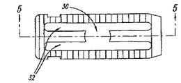
図1乃至図5は、第1平面要素またはプレート11と、第2平面要素またはプレート12間の位置取り用拡張部材またはスプレッダ20を含む、椎間スペーサ装置10を示す。プレート11、12は、1個以上の接続部材14によって接続される。接続部材は、プレート11、12を互いに接近位置に保持すると共に、他方、それらのプレートが側方に移動して拡張し、互いに離れることも可能とする。
FIGS. 1-5 illustrate an
図1および図2は、U型拡張部材20の一つの実施態様である。この拡張部材20は、第1幅を有する末端セクション6、および、この二つの末端セクション6の間に設けられる陥凹セクション8を含む。二つのプレート11、12の間に延びる長手通路は異なる直径を持つ。そのため、通路は、比較的広い中央部分7、および、広い中央部分の両側に設けられるより狭いチャンネル9を持つ。椎間スペーサ装置が未拡張状態にある時、スプレッダ20の第1末端セクション6は、第1および第2プレート11、12の間に設けられるアッセンブリの、対応する広大セクション7の中に保持される。スプレッダ20の陥凹セクション8は、第1および第2プレート11、12の間に形成される狭小チャンネル9の中に配置される。さらに、拡張部材が、椎間スペーサ装置10のプレート11、12の間に部分的に挿入されている時、椎間スペーサは未拡張形態に留まる。従って、拡張部材20は、埋め込み前に、スプレッダ20を表面プレート11、12の間に滑り込ませることによって、椎間スペーサ装置とあらかじめ集合することが可能である。
1 and 2 show one embodiment of the U-shaped
図3、4、および5は、拡張部材20の挿入前における、プレート11、12、および接続部材14の例示の画像を示す。この実施態様の局面によれば、プレート11、12はさらに、椎体(図示せず)の端面に接触するための外表面22を含む。図示のように、プレート11、12の外表面22は、椎体に対して椎間スペーサ装置を一定位置に保持するための嵌合表面を実現するために、複数の、互いに隔てられた長手陥凹、溝、または、鋸歯状辺縁を有する、平らな、不連続表面である。それとは別に、外表面は、実質的に滑らかであってもよい。さらに別の実施態様によれば、椎体に対して椎間スペーサ装置を一定位置に保持するために、従来技術で既知の、別の固定機構を使用することも可能である。
3, 4 and 5 show exemplary images of the
本発明のさらに別の局面によれば、椎間スペーサ装置は、移植ポートとして、または、BMPおよび粉砕骨を受容し、それによって融合を助長できるように、椎間スペーサ装置の中央にスペース30を残すように加工される。
According to yet another aspect of the present invention, the intervertebral spacer device provides a
図6Aおよび図6Bは、拡張部材20、および、非嵌合または萎縮位置において集束された椎間スペース装置10を示す。図7Aおよび図7Bは、嵌合または拡張位置における椎間スペーサ装置を示す。さらに具体的には、拡張部材20がユーザーによって前方に移動されると、末端セクション6がチャンネル9に押し込まれる。該末端セクション6が、チャンネル9の直径よりも大きな幅を持っている場合、拡張メンバー20の末端セクション6は、プレート11、12を引き離し、このように椎間スペーサ装置10のプレートを互いに引き離すことによって該椎間スペーサ装置を拡張する。
6A and 6B show the
図6Bおよび図7Bに示すように、装置は、萎縮全体高H1および拡張全体高H2を持つ。H1からH2への装置高の増加は、拡張部材の挿入によって第1および第2プレートが互いに引き離されたことによる。操作時、萎縮状態の装置が選択された円板空間に打撃挿入され、一旦所定の場所に納められたならば、拡張部材が嵌合され、装置の高さを拡張する。装置は、高さのより低い萎縮形状では、外科医による埋め込みをより容易にし、他方で、円板部位に対する損傷を最小にする。 As shown in FIGS. 6B and 7B, the device has an atrophy overall height H 1 and an expanded overall height H 2 . The increase in device height from H 1 to H 2 is due to the first and second plates being pulled apart from each other by insertion of the expansion member. In operation, once the device in the atrophied state is struck and inserted into the selected disc space and once placed in place, the expansion member is fitted to expand the height of the device. The device is easier to implant by the surgeon at the lower atrophic shape, while minimizing damage to the disc site.
本発明の局面によれば、拡張部材20はさらに、接続部材14の各側面において、椎間スペーサ装置10のスロット32に嵌合する保持タブ16を含む。このタブ16は、拡張部材20を所定の位置に納めるようにガイドしてもよい。それとは別に、タブ16はまた、図7Aおよび図7Bに示すように、椎間スペーサ装置10が拡張位置に置かれ、拡張部材20が嵌合した際、拡張部材20を所定の場所にロックするように働いてもよい。
In accordance with aspects of the present invention, the
経椎間孔腰椎体融合術(TLIF)
ここで図8乃至図10を参照すると、例示の椎間スペーサ装置140が示される。この椎間スペーサ装置140は、病気で冒された、または損傷された脊柱円板の代替となるが、より詳細には、経椎間孔腰椎体融合術(TLIF)において使用される。TLIFは、円板空間に対する後側方アプローチである。通常、対面関節が除去されて、神経孔を介して円板空間への接近が図られる。外科医にとっては比較的高度の技術が要求されるが、このアプローチでは、神経要素の操作を無しで済ませることができるので、術後の神経欠陥の危険度が抑えられる。さらに、軟部組織の多くが無傷で残されるため、この技術は、比較的侵襲性の低いクラスに分類される。
Transvertebral foramen lumbar fusion (TLIF)
With reference now to FIGS. 8-10, an exemplary
通常、この手術アプローチによれば、単一インプラントが設置され、骨移植材料(例えば、自家移植片またはBMP)によって囲まれる。TLIFインプラントは中空である必要はない。なぜなら、椎体の端面プレートの間に融合物質用に十分な空間が利用可能だからである。 Typically, according to this surgical approach, a single implant is placed and surrounded by a bone graft material (eg, autograft or BMP). The TLIF implant need not be hollow. This is because sufficient space is available between the end plates of the vertebral bodies for the fusion material.
TLIF法用の既知の手術プロトコールによれば、インプラントは、円板空間の前面に設置されるので、実質的な融合物質用の空間が得られ、正常な矢状アラインメント(すなわち、脊柱前湾症)の形成が実現される。一つの実施態様によれば、TLIFインプラントはカシューナッツ型またはバナナ型をしており、円板空間への挿入を促進するために先細りの先端を持っていてもよい。表面組織(溝、凹み、粗い表面、棘等)は、神経孔の中をインプラントが移動するのを阻止するような方向性を持つことが考えられる。インプラントの前方または後方の移動は、周囲の靭帯の存在によって阻止されると予想される。術時、TLIF椎間スペーサ装置を埋め込む主要目的は、病的椎骨を固定し、脊柱円板腔を回復し、矢状アラインメントを実証し、かつ、椎体間骨融合のための環境を実現することである。 According to known surgical protocols for the TLIF procedure, the implant is placed in front of the disc space, thus providing a substantial space for fusion material and normal sagittal alignment (ie, prespondylosis). ) Is realized. According to one embodiment, the TLIF implant is cashew-nut or banana-shaped and may have a tapered tip to facilitate insertion into the disc space. It is conceivable that surface tissues (grooves, dents, rough surfaces, spines, etc.) have a directionality that prevents the implant from moving through the nerve holes. It is expected that movement of the implant forward or backward will be prevented by the presence of the surrounding ligament. During surgery, the primary purpose of implanting the TLIF intervertebral spacer device is to fix the pathological vertebra, restore the spinal disc space, demonstrate sagittal alignment, and provide an environment for interbody fusion That is.
インプラントの最終的設置を除いては、斜方手術法はTLIF手術法と近似する。すなわち、斜方手術法は、インプラントを円板空間の中央面に設置する。移植片は、インプラントの前方と後方に設置することが可能である。それとは別に、斜方インプラントは長方形足型を持ってもよい。インプラントは、前湾症を矯正するために、円板空間を横切って傾斜角をもって置かれることになるので、インプラントは、最高辺縁がインプラントのもっとも前方隅に、最短辺縁がインプラントのもっとも後方隅に来るように設置される。 Except for the final placement of the implant, the orthopedic procedure is similar to the TLIF procedure. That is, in the oblique operation method, the implant is placed on the center plane of the disc space. The implant can be placed in front of and behind the implant. Alternatively, the oblique implant may have a rectangular foot shape. The implant will be placed at a tilt angle across the disc space to correct the anterior bay disease, so that the highest edge is at the most anterior corner of the implant and the shortest edge is at the most posterior side of the implant. Installed to come to the corner.
図8乃至図10は、例えば、TLIFアプローチに使用される、カシューナッツ型またはバナナ型の例示インプラントを示す。さらに具体的には、図8は、TLIF手術法に使用される、カシューナッツ型椎間スペーサ装置の、前方等尺平面図を示す。図9は、図8のカシューナッツ型椎間スペーサ装置の、等尺底面図を示す。図10は、図8のカシューナッツ型椎間スペーサ装置の平面図を示す。 FIGS. 8-10 show exemplary implants of the cashew nut type or banana type, for example, used in the TLIF approach. More specifically, FIG. 8 shows an anterior isometric plan view of a cashew nut-type intervertebral spacer device used in TLIF surgery. FIG. 9 shows an isometric bottom view of the cashew nut type intervertebral spacer device of FIG. FIG. 10 shows a plan view of the cashew nut type intervertebral spacer device of FIG.
カシューナッツ型椎間スペーサ装置140は、第1表面プレート114、および、接続部材124によって近傍位置に保持される第2表面プレート115を含む。それとは別に、第1表面プレート114と第2表面プレート115とは、拡張部材116に滑走可能に接続されてもよい。滑走部材116は、プレート114、115の間に挟まれ、その間を移動することが可能である。拡張部材116は、第1未拡張位置と第2拡張位置の間を移動し、そうすることによって椎間スペーサ装置140を、比較的低い全体高さを持つ未拡張位置と、比較的高い全体高さを持つ拡張位置の間を移動させる。図8乃至図10の椎間スペーサ装置140は、未拡張状態にある椎間スペーサ装置、例えば、埋め込み前装置として示される。
The cashew nut-type
この実施態様の局面によれば、拡張部材116は、椎間スペーサ装置140が拡張位置に来るように拡張部材116が嵌合した場合に、拡張部材を、プレート114、115とロック関係に保持するためのタブ122を含む。この実施態様の局面によれば、タブ122は、固定された突起であってもよいし、後退可能な凹みであってもよい。図示の実施態様に示したように、タブ122は、プレートの開口118の中に保持されてもよい。それとは別に、プレートは、タブを軸揃えする、および/または保持するために、溝またはその他のアラインメントガイドを含んでもよい。さらに別の実施態様によれば、プレート114、115は、拡張部材を保持するためのタブを含んでもよい。さらに別の実施態様によれば、拡張部材116は、ラッチ、ピン、キャッチ、または、従来技術で既知のその他の保持機構によって、プレートに対してロック位置に固定されてもよい。
According to aspects of this embodiment, the
図11は、拡張部材を拡張する前の萎縮状態にある椎間スペーサ装置を示す。図12は、図11の椎間スペーサ装置に使用されるダウエルとして構成される拡張部材を示す。図11に示すように、二つのダウエルまたはピン230は椎間スペーサ装置234の中に含まれて、プレートを拡げ、椎間スペーサ装置を拡張する手段となる。図12に示すように、ダウエル230は、太い末端236と、より細い、または陥凹した中央部分238を含む。ダウエルを、未嵌合または非拡張位置に設置した場合、第1肥大末端236は、椎間スペーサ装置の陥凹に留まり、椎間スペーサ装置234が萎縮状態を維持するのを可能とする。
FIG. 11 shows the intervertebral spacer device in an atrophied state prior to expanding the expansion member. FIG. 12 shows an expansion member configured as a dowel used in the intervertebral spacer device of FIG. As shown in FIG. 11, two dowels or
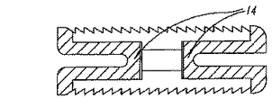
図13は、本発明の原理に従って設けられる、前湾角Lを持つ椎間スペーサ装置の別態様を示す。図13に示すように、椎間スペーサ装置は、第2辺縁に比べて、より高い第1辺縁を持つ。一つの実施態様では、前方辺縁は、後方辺縁よりも高い。従って、椎間スペーサ装置の両平面は互いに離反することになり、これは前湾症の整復を助長する。それとは別に、前湾整復は、テーパー型拡張部材またはクリップと定常厚のプレート、または、テーパー型拡張部材と、一方または両方がテーパー型のプレートとの組み合わせによって実現することが可能である。 FIG. 13 illustrates another embodiment of an intervertebral spacer device having an anterior bay angle L provided in accordance with the principles of the present invention. As shown in FIG. 13, the intervertebral spacer device has a first edge that is higher than the second edge. In one embodiment, the front edge is higher than the rear edge. Thus, both planes of the intervertebral spacer device will be spaced apart from each other, which aids in the reduction of anterior bay disease. Alternatively, the front bay reduction can be achieved by a combination of a taper-type expansion member or clip and a plate of constant thickness, or a taper-type expansion member and one or both taper-type plates.
例えば、図14は、楔型拡張部材442を持つ椎間スペーサ装置の別態様を示す。さらに別の局面によれば、拡張部材は、該拡張部材が嵌合し椎間スペーサが拡張位置に来た場合、後端に比べより高い前端を形成するように、シム、または任意の角度付き拡大手段と同様に、テーパー型を取ってもよい。
For example, FIG. 14 shows another embodiment of an intervertebral spacer device having a wedge-shaped
図15は、椎間スペーサ装置の中心と、椎間スペーサ装置の外縁に沿って整列して第1プレート456と第2プレート458を結合する、接続部材454とに整列する拡張部材452を有する、椎間スペーサ装置の別態様を示す。
FIG. 15 has an
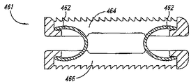
図16は、接続要素として別々のバイアス要素462を有する、椎間スペーサ装置の別態様を示す。この実施態様の局面によれば、第1プレート464および第2プレート466は、バイアス要素462によって、互いに近い位置に、例えば、互いに実質的に平行位置に屈曲性に保持される。このバイアス要素462は、椎間スペーサ装置461の第1プレート464および第2プレート466を相対的位置に維持しながら、他方では、後述するように、拡張部材が椎間スペーサ装置の両プレートの間に挿入された場合、プレートが互いに離れて移動するのを可能とするように、バネ、c型クランプ、クランプ、コイル、クリップ、または、その他の接続要素となっていてもよい。
FIG. 16 illustrates another embodiment of an intervertebral spacer device having a
前方腰椎体融合術
ここで図17乃至図21を参照すると、例示の椎間スペーサ装置540が示される。この椎間スペーサ装置540は、病気で冒された、または損傷された脊柱円板の代替となるが、より詳細には、前方腰椎体融合術において使用される。前方腰椎体融合術(ALIF)は、円板スペースに対する前方アプローチである。腹腔を通して脊柱の前面に達するために、第2の一般外科医が用いられることが多い。前方の血管は移動させられ、前縦靭帯は摘出される。後方の神経要素への接近は実現されない。
Anterior Lumbar Fusion Fusion Referring now to FIGS. 17-21, an exemplary
高齢患者、または血管硬化症を抱える患者ではALIFは比較的危険度が高い。第2の外科医のためのコスト/必要性は障害となる場合がある。それでもなお、円板腔は極端に潰れているが神経狭窄症がほとんど無い場合には、このアプローチは理想的である。 In elderly patients or patients with vascular sclerosis, ALIF is relatively high risk. The cost / need for the second surgeon can be an obstacle. Nevertheless, this approach is ideal when the disc space is extremely crushed but there is little nerve stenosis.
前方アプローチには、典型的には、大型の、単一インプラントが使用される。このインプラントは通常中空であり、かつ、隣接する椎体のサイズと形を持つ。前方および頚椎椎間融合と、腰椎椎間融合については、インプラントまたは椎間スペーサ装置は、使用される椎間スペーサ装置の直径に関して異なる。インプラントは、典型的には、骨移植材料、例えば、自家移植片またはBMPによってパック、または、取り囲まれる。 The anterior approach typically uses a large, single implant. This implant is usually hollow and has the size and shape of the adjacent vertebral bodies. For anterior and cervical intervertebral fusion and lumbar intervertebral fusion, the implant or intervertebral spacer device differs with respect to the diameter of the intervertebral spacer device used. The implant is typically packed or surrounded by a bone graft material, such as an autograft or BMP.
さらに具体的には、図17は、例えば、ALIF、または頚椎処置に使用される、環状椎間スペーサ装置を示す。本発明の別態様によれば、椎間スペーサ装置は、円形、長方形、または円板形であってもよい。椎間スペーサ装置540は、接続部材524によって結合される第1表面プレート514および第2表面プレート515を含む。別態様として、第1表面プレート514および第2表面プレート515は、拡張部材516に直接結合される。拡張部材516は、プレート514、515の間に挟まれ、その間を移動することが可能である。拡張部材は、椎間スペーサ装置を、第1未拡張位置から第2拡張位置へ移動させる。図17乃至図21の、前方または頚椎用椎間スペーサ装置は、例えば、椎間スペーサ装置へ埋め込む前の、未拡張位置にあるところが示される。
More specifically, FIG. 17 shows an annular intervertebral spacer device used, for example, for ALIF or cervical spine procedures. According to another aspect of the present invention, the intervertebral spacer device may be circular, rectangular, or disc-shaped. The
図17、19、20、および21に示すように、椎間スペーサ装置の上縁のタブ517は開口519を含む。この開口は、ネジ、ステープル、ピン等によって、椎間スペーサ装置を椎体に付着させるために使用されてもよい。別態様として、椎間スペーサ装置を椎体に付着させるために、椎間スペーサ装置の中に含まれるフランジ、ループ、またはその他の固定手段を用いてもよい。それとは別に、図18に示すように、装置はタブ517無しの状態で提供されてもよい。
As shown in FIGS. 17, 19, 20, and 21, the
本発明の局面によれば、拡張部材516は、該拡張部材が嵌合して椎間スペーサ装置を拡張位置に設置した場合、拡張部材を、プレート514、515に対してロック関係に維持するためのタブ522を含む。別態様として、プレートは、拡張部材を保持するためのタブを含んでもよい。本発明のさらに別の実施態様によれば、拡張部材は、ラッチ、ピン、キャッチ、または、従来技術で既知のその他の保持機構によって、プレートに対してロック位置に固定することも可能である。
According to aspects of the present invention, the
図21に示すように、拡張部材は516は、第1幅を有する末端セクション526と、二つの末端セクション526の間に設けられる陥凹セクション528とを持つ。二つのプレート514、515の間に延びる長手通路は異なる直径を持つ。そのため、通路は、比較的広い中央部分530、および、広い中央部分の両側に設けられるより狭いチャンネル532を持つ。椎間スペーサ装置が未拡張状態にある時、拡張部材516の第1末端セクション526は、第1および第2プレート514、515の間に設けられるアッセンブリの、対応する広大セクション530の中に保持される。拡張部材516の陥凹セクション528は、第1および第2プレート514、515の間に形成される狭小チャンネル532の中に配置される。さらに、拡張部材が、椎間スペーサ装置のプレートの間に部分的に挿入されている時、椎間スペーサは未拡張形態に留まる。拡張部材を、椎間スペーサ装置のプレート間のある位置まで移動させることは、拡張部材516のより広い末端セクション528がプレート514、515を引き離すように作用し、従って該椎間装置を拡張する。
As shown in FIG. 21, the
さらに図21に示すように、プレート514、515は先細りになって前湾整復を形成する。それとは別に、前湾整復は、テーパー型拡張部材516またはクリップと定常厚のプレート、または、後述するように、テーパー型拡張部材と、一方または両方がテーパー型のプレートとの組み合わせによって実現することが可能である。拡張部材またはクリップは、該拡張部材が嵌合または拡張位置に納まった場合、後端に比べより高い前端を形成し、そのためにプレートの厚みが定常に維持されるように、テーパー型、例えば、楔型、またはその他の角度付き拡大手段と同様の形を取ってもよい。
Further, as shown in FIG. 21, the
側方および後方腰椎体融合術
ここで図22乃至図26を参照すると、例示の椎間スペーサ装置640が示される。この椎間スペーサ装置640は、病気で冒された、または損傷された脊柱円板の代替となるが、より詳細には、後方または側方腰椎体融合術において使用される。後方腰椎体融合術(PLIF)は、円板スペースに対する後方および正中アプローチである。通常、椎弓板部分は取り除かれる。黄色靭帯および後縦靭帯は摘出される。脊髄/硬膜嚢は、円板腔への接近を図るために移動させられる。
Lateral and Posterior Lumbar Fusion Fusion Referring now to FIGS. 22-26, an exemplary
PLIFアプローチは、比較的広く実施され、技術的要求度は比較的低いが、患者にとっては、例えば、TLIF技術よりも危険度が高い。神経要素の操作は、それらの要素に対して損傷を及ぼす可能性がある。従来は、二つのインプラントを、それぞれ正中線の両側に設置する。捻じ込み式インプラントの場合、形は通常円筒形である。打ち込み式インプラントの場合、形は通常直方体である。直方体インプラントは、1よりも大きい高対幅比を持つことによって、硬膜の移動距離を狭めるので、好ましい。 The PLIF approach is relatively widely implemented and has relatively low technical requirements, but it is more dangerous for patients than, for example, TLIF technology. Manipulation of neural elements can cause damage to those elements. Conventionally, two implants are installed on each side of the midline. In the case of screw-type implants, the shape is usually cylindrical. In the case of implantable implants, the shape is usually a cuboid. A rectangular parallelepiped implant is preferred because it has a high to width ratio greater than 1, thereby reducing the distance traveled by the dura mater.
PLIFインプラントは、骨移植材料用の余分のスペースを与えるよう中空となっていることが多い。2個のインプラントを用いることは、骨移植材料の設置のために残される円板腔の量を下げるので、中空インプラント腔によって骨移植のための余分の空間が得られる。インプラントは、通常、脊柱の適正な矢状アラインメントを実現するために、前方から後方に向かうテーパーを持つ。上面および下面は、椎骨の端面とインプラントの嵌合の緊密性を増すために凸型となっていてもよい。表面組織は、インプラントの後方移動を阻止するような形状を持つ。 PLIF implants are often hollow to provide extra space for bone graft material. Using two implants reduces the amount of disc space left for placement of bone graft material, so that the hollow implant cavity provides extra space for bone grafting. Implants typically have an anterior to posterior taper to achieve proper sagittal alignment of the spinal column. The upper and lower surfaces may be convex to increase the tightness of the vertebra end face and implant fit. The surface tissue is shaped to prevent posterior movement of the implant.
アプローチがPLIFアプローチに対して直角となることを除いては、椎体融合における側方アプローチはPLIFに近似する。この場合も、二つのインプラントが使用される。これらのインプラントは、円筒形の捻じ込み式インプラントでも、または、直方体の打ち込み式インプラントであってもよい。二つのプラントは、ほとんどの場合、移植用の空間をほとんど残さずに設置されるので、インプラントは、移植片設置用に中空である必要がある。前湾整復のためには、インプラントは、通常、前側から後ろ側に向かうテーパーを持つ。 The lateral approach in vertebral body fusion approximates PLIF, except that the approach is perpendicular to the PLIF approach. Again, two implants are used. These implants may be cylindrical screw-in implants or rectangular implants. Since the two plants are installed in most cases leaving little space for implantation, the implant needs to be hollow for graft placement. For front bay reduction, the implant usually has a taper from the front side to the back side.
さらに具体的には、図22乃至図26は、側方、斜行、またはPLIF処置において使用される、長方形型椎間スペーサ装置を示す。本発明の別の実施態様によれば、椎間スペーサ装置は、正方形型または多角形型であってもよい。 More specifically, FIGS. 22-26 illustrate a rectangular intervertebral spacer device used in a lateral, skewed, or PLIF procedure. According to another embodiment of the present invention, the intervertebral spacer device may be square or polygonal.
椎間スペーサ装置640は、接続部材624によって結合される第1表面プレート614および第2表面プレート615を含む。別態様として、第1表面プレート614および第2表面プレート615は、拡張部材616に直接滑走自在に結合される。本明細書に記載されるさらに別の実施態様によれば、拡張部材616は、クリップ、バネ、またはクランプのようなバイアス要素であってもよい。図22に示すように、拡張部材616は、プレート614、615の間に挟まれ、その間を移動することが可能である。
図25に示すように、拡張部材616は、第1幅を有する末端セクション626と、二つの末端セクション626の間に設けられる陥凹セクション628とを持つ。二つのプレート614、615の間に延びる長手通路は異なる直径を持つ。そのため、通路は、比較的広い中央部分630、および、広い中央部分の両側に設けられるより狭いチャンネル632を持つ。椎間スペーサ装置が未拡張状態にある時、拡張部材616の第1末端セクション626は、第1および第2プレート614、615の間に設けられるアッセンブリの、対応する広大セクション630の中に保持される。拡張部材616の陥凹セクション628は、第1および第2プレート614、615の間に形成される狭小チャンネル632の中に配置される。さらに、拡張部材が、椎間スペーサ装置のプレートの間に部分的に挿入されている時、椎間スペーサは未拡張形態に留まる。拡張部材を、椎間スペーサ装置のプレート間の完全嵌合位置まで移動させることは、拡張部材616のより広い末端セクション628がプレート614、615を引き離すように作用し、従って該椎間装置を拡張する。このようにして、拡張部材は、第1の未拡張位置と第2の拡張位置の間を移動する。図22乃至図26の、前方または頚椎用椎間スペーサ装置は、例えば、椎間スペーサ装置へ埋め込む前の、未拡張位置にあるところが示される。
As shown in FIG. 25, the
本発明の局面によれば、拡張部材616は、該拡張部材をプレートの間にガイドするための、および/または、該拡張部材がプレート間に完全に挿入された場合、拡張部材を、プレート614、615に対してロック関係に維持するためのタブ622を含む。別態様として、プレートは、拡張部材を保持するためのタブを含んでもよい。本発明のさらに別の実施態様によれば、拡張部材は、ラッチ、ピン、キャッチ、または、従来技術で既知のその他の保持機構によって、プレートに対してロック位置に固定することも可能である。
In accordance with aspects of the present invention, the
図26に示すように、プレート614、615は先細りになって前湾整復を形成する。それとは別に、前湾整復は、テーパー型拡張部材またはクリップと定常な椎間スペーサ装置、または、後述するように、テーパー型拡張部材とテーパー型の椎間スペーサ装置との組み合わせによって実現することが可能である。
As shown in FIG. 26, the
本発明の局面によれば、本発明に従って設けられる椎間スペーサ装置は、様々な材料、例えば、ステンレススチール、炭素線維材料、各種プラスチック、チタン、セラミックス、PEEK、または生体吸収性材料を含む材料によって製造されてもよいが、ただし材料はこれらに限定されない。材料は、非多孔性で、不活性で、生物学的に適合的であってもよい。材料はさらに、剛性で、非屈撓性、負荷担持材料、好ましくは弾性変形を示さない材料を形成するのに十分な特徴を持っていてもよい。 According to an aspect of the present invention, the intervertebral spacer device provided in accordance with the present invention can be made of a variety of materials, such as stainless steel, carbon fiber materials, various plastics, titanium, ceramics, PEEK, or materials including bioabsorbable materials. However, the material is not limited to these. The material may be non-porous, inert and biologically compatible. The material may further have sufficient characteristics to form a rigid, non-flexible, load bearing material, preferably a material that does not exhibit elastic deformation.
椎間スペーサ装置の成分、例えば、本明細書に記載されるプレートおよび拡張部材は、開示の特性を実現するために、加工および/または金型成形されてもよい。椎間スペーサ装置の各成分は、同じ材料で製造されても、あるいは、異なる材料から製造されてもよい。 The components of the intervertebral spacer device, such as the plates and expansion members described herein, may be processed and / or molded to achieve the disclosed characteristics. Each component of the intervertebral spacer device may be manufactured from the same material or from different materials.
本明細書で論じられたように、また、本発明の別態様によれば、椎間スペーサ装置の形態は平行面を有するが、前湾整復のために、様々の方向性を持つ角度付き面を持つように製造することも可能である。本発明の一つの実施態様によれば、椎間スペーサ装置はまた、装置の嵌合は一端のみを拡張し、それによって前湾角を再現できるように構成することも可能である。本発明の別態様によれば、椎間スペーサ装置は、凸型の前方側壁および凹型の後方側壁を持ち、そのために、スペーサ装置を横切る平面に関して凹から凸の輪郭が実現される。一つの局面による椎間スペーサ装置は、経椎間孔腰椎体融合術法を実行可能とするためにカシューナッツ型である。本発明の別態様によれば、椎間スペーサは、正方形、多角形、または長方形型であってもよい。 As discussed herein, and in accordance with another aspect of the present invention, the intervertebral spacer device configuration has parallel surfaces, but angled surfaces with various orientations for anterior bay reduction. It is also possible to manufacture so that it has. According to one embodiment of the present invention, the intervertebral spacer device can also be configured so that the fitting of the device expands only at one end, thereby reproducing the anterior bay angle. According to another aspect of the present invention, the intervertebral spacer device has a convex anterior sidewall and a concave posterior sidewall, so that a concave to convex profile is realized with respect to a plane across the spacer device. An intervertebral spacer device according to one aspect is a cashew nut type to enable transforaminal lumbar fusion techniques. According to another aspect of the present invention, the intervertebral spacer may be square, polygonal, or rectangular.
本明細書に開示される椎間スペーサ装置についてはいくつかの利点が明らかである。椎間スペーサ装置を、萎縮または未拡張状態で挿入することが可能なので、外科医は、傷口を過剰に翻転することなくスペーサ装置を設置することが可能である。一旦所定の場所に設置したならば、スペーサ装置を嵌合すると、それによって椎間スペーサの拡張位置が実現され、椎体に対する衝撃を最小としつつ、脊柱円板腔の完全な回復が達成される。 Several advantages are apparent with the intervertebral spacer device disclosed herein. Because the intervertebral spacer device can be inserted in a deflated or unexpanded state, the surgeon can place the spacer device without excessive overturning of the wound. Once in place, the spacer device is mated, thereby providing an expanded position for the intervertebral spacer and achieving full recovery of the spinal disc space while minimizing impact on the vertebral body. .
例示の実施態様に関する上記説明は、要約書に記載されるものを含めて、網羅的であることを意図するものでも、本発明を、開示された正確な形態に限定することを意図するものでもない。本明細書において例示の目的のために特定の実施態様および例が記載されたが、当業者には認識されるように、本発明の精神および範囲から逸脱することなく、様々な等価的改変を実行することが可能である。本明細書において、本発明に関して与えられた教示は、椎間スペーサ装置には適用されるが、一般的に説明された、例示のカシューナッツ型経椎間孔スペーサ装置には必ずしも適用されない。 The above description of exemplary embodiments, including what is described in the abstract, is intended to be exhaustive or intended to limit the invention to the precise form disclosed. Absent. While specific embodiments and examples have been described herein for purposes of illustration, it will be appreciated by those skilled in the art that various equivalent modifications can be made without departing from the spirit and scope of the invention. It is possible to execute. Although the teachings provided herein with respect to the present invention apply to the intervertebral spacer device, they do not necessarily apply to the generally described exemplary cashew nut-type transvertebral spacer device.
前述の様々な実施態様を組み合わせてさらに別の実施態様を実現することも可能である。本明細書で引用された、および/または、出願データシートに列挙されたその全体である、米国特許、米国特許出願公報、米国特許出願、外国特許、外国特許出願、非特許出版物の全て。本発明の局面は、要すれば、各種特許、出願、および出版物のシステム、材料、および概念を採用し、それによって、本発明のさらに別の実施態様を実現可能とするよう修飾することが可能である。 It is also possible to realize further embodiments by combining the various embodiments described above. All of the US patents, US patent application publications, US patent applications, foreign patents, foreign patent applications, non-patent publications cited herein and / or in their entirety listed in the application data sheet. Aspects of the present invention can be modified to employ various patent, application, and publication systems, materials, and concepts, if desired, thereby enabling further embodiments of the present invention. Is possible.
上に詳述した説明の観点より、上記およびその他の変更を本発明に対し実行することが可能である。一般に、特許請求の範囲において用いられる用語は、本明細書および請求項で開示される特定の実施態様に本発明を限定するものと考えてはならず、請求項に従って動作する全ての椎間スペーサ装置を含むものと思料しなければならない。従って、本発明は、開示によっては限定されず、むしろその範囲は、付随する請求項によって完全に決定されるべきものである。 These and other changes can be made to the invention in light of the above detailed description. In general, the terms used in the claims should not be construed to limit the invention to the specific embodiments disclosed in the specification and the claims, and all intervertebral spacers operating according to the claims You must think of it as including equipment. Accordingly, the invention is not limited by the disclosure, but rather its scope is to be determined entirely by the appended claims.
Claims (21)
前記プレート間に結合し、第1位置から第2位置へ移動が可能であり、第2位置にある場合、前記の第1および第2プレートに対し力を及ぼし、椎間スペーサ装置の高さを増大させる拡張部材と、を含むことを特徴とする椎間スペーサ装置。 An implant body having a first plate coupled to and spaced apart from a second plate;
Coupled between the plates and movable from a first position to a second position, when in the second position, exerts a force on the first and second plates to increase the height of the intervertebral spacer device An intervertebral spacer device comprising: an expanding member for augmentation.
該第1平面要素から隔てられる第2平面要素と、
該第1平面要素を該第2平面要素に結合させ、該第1平面要素を該第2平面要素から隔てて保持する接続要素と、
前記の第1および第2平面要素の間に配置され、平面要素間を移動可能なスペーサ装置と、
を含むことを特徴とする椎間スペーサ装置。 A first planar element;
A second planar element separated from the first planar element;
A connecting element that couples the first planar element to the second planar element and holds the first planar element apart from the second planar element;
A spacer device disposed between the first and second planar elements and movable between the planar elements;
An intervertebral spacer device comprising:
前記第1平面要素の隣接面において該タブに向き合って設けられる相互的受容溝と、をさらに含み、
該タブは、受容溝と嵌合し、前記スペーサ装置を選択位置に保持することを特徴とする請求項10に記載の椎間スペーサ装置。 A tab included on the outer surface of the spacer device;
A reciprocal receiving groove provided facing the tab on an adjacent surface of the first planar element;
11. The intervertebral spacer device of claim 10, wherein the tab engages a receiving groove and holds the spacer device in a selected position.
該第1円板型要素に近接し、該第1円板型要素との間に空間を有する第2円板型要素と、
前記の第1および第2要素の間に挟持されるスペーサ装置と、を含み、
ここで該スペーサ装置は該要素間を移動可能であり、該スペーサ装置は第1側面と第2側面を有し、該第1側面と該第2側面は、前記の第1要素および第2要素に付着する接続機構を有し、接続機構は、前記の第1要素と第2要素を該スペーサ装置に対し滑走可能として保持し、脊柱に埋め込まれた際、前記の第1要素、第2要素、およびスペーサ装置は共同して椎間補強を実現することを特徴とする椎間スペーサ装置。 First disc-shaped element;
A second disk-shaped element proximate to the first disk-shaped element and having a space between the first disk-shaped element;
A spacer device sandwiched between the first and second elements,
Wherein the spacer device is movable between the elements, the spacer device having a first side and a second side, wherein the first side and the second side are the first and second elements. A connection mechanism that attaches to the spacer device, the connection mechanism holding the first element and the second element slidable relative to the spacer device, and the first element and the second element when implanted in the spinal column. The intervertebral spacer device is characterized in that the spacer device jointly realizes intervertebral reinforcement.
脊柱の腰椎領域に拡張可能椎間スペーサ装置を打撃挿入するステップと、
該インプラントを拡張するために一体的スプレッダを嵌合するステップと、を含み、前記スプレッダの嵌合は、該スプレッダを、インプラントの第1および第2要素の間に移動させるステップを含み、該第1および該第2要素が互いに引き離されることを特徴とする椎間スペーサ装置の埋込方法。 A method of implanting an intervertebral spacer device comprising:
Striking and inserting an expandable intervertebral spacer device into the lumbar region of the spine;
Fitting an integral spreader to expand the implant, the fitting of the spreader comprising moving the spreader between first and second elements of the implant; A method of implanting an intervertebral spacer device, wherein the first element and the second element are pulled apart from each other.
Applications Claiming Priority (6)
| Application Number | Priority Date | Filing Date | Title |
|---|---|---|---|
| US62209704P | 2004-10-25 | 2004-10-25 | |
| US68718505P | 2005-06-03 | 2005-06-03 | |
| US68750005P | 2005-06-03 | 2005-06-03 | |
| US68749905P | 2005-06-03 | 2005-06-03 | |
| US68749805P | 2005-06-03 | 2005-06-03 | |
| PCT/US2005/038546 WO2006047587A2 (en) | 2004-10-25 | 2005-10-25 | Expandable intervertebral spacer method and apparatus |
Publications (2)
| Publication Number | Publication Date |
|---|---|
| JP2008517723A true JP2008517723A (en) | 2008-05-29 |
| JP2008517723A5 JP2008517723A5 (en) | 2008-12-25 |
Family
ID=36228417
Family Applications (1)
| Application Number | Title | Priority Date | Filing Date |
|---|---|---|---|
| JP2007539067A Withdrawn JP2008517723A (en) | 2004-10-25 | 2005-10-25 | Expandable intervertebral spacer method and device |
Country Status (8)
| Country | Link |
|---|---|
| US (1) | US20060129244A1 (en) |
| EP (1) | EP1811927A2 (en) |
| JP (1) | JP2008517723A (en) |
| KR (1) | KR20070104337A (en) |
| AU (1) | AU2005299397A1 (en) |
| CA (1) | CA2585450A1 (en) |
| IL (1) | IL182778A0 (en) |
| WO (1) | WO2006047587A2 (en) |
Cited By (4)
| Publication number | Priority date | Publication date | Assignee | Title |
|---|---|---|---|---|
| JP2010518987A (en) * | 2007-02-21 | 2010-06-03 | ベンベニュー メディカル, インコーポレイテッド | Spinal therapy device |
| JP2014518512A (en) * | 2011-03-11 | 2014-07-31 | エフビーシー デバイス エーピーエス | Spine implant, pretreatment instrument and method of use |
| JP2016527056A (en) * | 2013-08-07 | 2016-09-08 | グローバス メディカル インコーポレイティッド | Expandable fixed device and installation method thereof |
| JP2021517014A (en) * | 2018-03-06 | 2021-07-15 | イーアイティー・エマージング・インプラント・テクノロジーズ・ゲーエムベーハーEit Emerging Implant Technologies Gmbh | Angle-adjustable facet cage with integrated ratchet assembly |
Families Citing this family (322)
| Publication number | Priority date | Publication date | Assignee | Title |
|---|---|---|---|---|
| CA2594492A1 (en) | 1999-03-07 | 2000-09-14 | Active Implants Corporation | Method and apparatus for computerized surgery |
| FR2897259B1 (en) | 2006-02-15 | 2008-05-09 | Ldr Medical Soc Par Actions Si | INTERSOMATIC TRANSFORAMINAL CAGE WITH INTERBREBAL FUSION GRAFT AND CAGE IMPLANTATION INSTRUMENT |
| FR2824261B1 (en) | 2001-05-04 | 2004-05-28 | Ldr Medical | INTERVERTEBRAL DISC PROSTHESIS AND IMPLEMENTATION METHOD AND TOOLS |
| FR2827156B1 (en) | 2001-07-13 | 2003-11-14 | Ldr Medical | VERTEBRAL CAGE DEVICE WITH MODULAR FASTENING |
| US6793678B2 (en) | 2002-06-27 | 2004-09-21 | Depuy Acromed, Inc. | Prosthetic intervertebral motion disc having dampening |
| FR2846550B1 (en) | 2002-11-05 | 2006-01-13 | Ldr Medical | INTERVERTEBRAL DISC PROSTHESIS |
| AU2004212942A1 (en) | 2003-02-14 | 2004-09-02 | Depuy Spine, Inc. | In-situ formed intervertebral fusion device |
| US20040267367A1 (en) | 2003-06-30 | 2004-12-30 | Depuy Acromed, Inc | Intervertebral implant with conformable endplate |
| US7753958B2 (en) | 2003-08-05 | 2010-07-13 | Gordon Charles R | Expandable intervertebral implant |
| US7909869B2 (en) | 2003-08-05 | 2011-03-22 | Flexuspine, Inc. | Artificial spinal unit assemblies |
| US8052723B2 (en) | 2003-08-05 | 2011-11-08 | Flexuspine Inc. | Dynamic posterior stabilization systems and methods of use |
| JP4996927B2 (en) | 2004-02-04 | 2012-08-08 | エル・デ・エール・メデイカル | Intervertebral disc prosthesis |
| FR2865629B1 (en) | 2004-02-04 | 2007-01-26 | Ldr Medical | INTERVERTEBRAL DISC PROSTHESIS |
| US8636802B2 (en) | 2004-03-06 | 2014-01-28 | DePuy Synthes Products, LLC | Dynamized interspinal implant |
| FR2869528B1 (en) | 2004-04-28 | 2007-02-02 | Ldr Medical | INTERVERTEBRAL DISC PROSTHESIS |
| WO2006026425A2 (en) | 2004-08-25 | 2006-03-09 | Spine Wave, Inc. | Expandable interbody fusion device |
| WO2006034436A2 (en) | 2004-09-21 | 2006-03-30 | Stout Medical Group, L.P. | Expandable support device and method of use |
| US8597360B2 (en) | 2004-11-03 | 2013-12-03 | Neuropro Technologies, Inc. | Bone fusion device |
| US8172855B2 (en) | 2004-11-24 | 2012-05-08 | Abdou M S | Devices and methods for inter-vertebral orthopedic device placement |
| FR2879436B1 (en) | 2004-12-22 | 2007-03-09 | Ldr Medical | INTERVERTEBRAL DISC PROSTHESIS |
| US7959675B2 (en) * | 2005-04-08 | 2011-06-14 | G&L Consulting, Llc | Spine implant insertion device and method |
| US11903849B2 (en) | 2005-04-12 | 2024-02-20 | Moskowitz Family Llc | Intervertebral implant and tool assembly |
| US7942903B2 (en) | 2005-04-12 | 2011-05-17 | Moskowitz Ahmnon D | Bi-directional fixating transvertebral body screws and posterior cervical and lumbar interarticulating joint calibrated stapling devices for spinal fusion |
| WO2007009107A2 (en) | 2005-07-14 | 2007-01-18 | Stout Medical Group, P.L. | Expandable support device and method of use |
| US8366773B2 (en) * | 2005-08-16 | 2013-02-05 | Benvenue Medical, Inc. | Apparatus and method for treating bone |
| AU2006279558B2 (en) | 2005-08-16 | 2012-05-17 | Izi Medical Products, Llc | Spinal tissue distraction devices |
| WO2008103781A2 (en) | 2007-02-21 | 2008-08-28 | Benvenue Medical, Inc. | Devices for treating the spine |
| FR2891135B1 (en) | 2005-09-23 | 2008-09-12 | Ldr Medical Sarl | INTERVERTEBRAL DISC PROSTHESIS |
| FR2893838B1 (en) | 2005-11-30 | 2008-08-08 | Ldr Medical Soc Par Actions Si | PROSTHESIS OF INTERVERTEBRAL DISC AND INSTRUMENTATION OF INSERTION OF THE PROSTHESIS BETWEEN VERTEBRATES |
| US7887595B1 (en) | 2005-12-05 | 2011-02-15 | Nuvasive, Inc. | Methods and apparatus for spinal fusion |
| US7988695B2 (en) * | 2005-12-21 | 2011-08-02 | Theken Spine, Llc | Articulated delivery instrument |
| US20070162132A1 (en) | 2005-12-23 | 2007-07-12 | Dominique Messerli | Flexible elongated chain implant and method of supporting body tissue with same |
| US8118869B2 (en) | 2006-03-08 | 2012-02-21 | Flexuspine, Inc. | Dynamic interbody device |
| US7976549B2 (en) * | 2006-03-23 | 2011-07-12 | Theken Spine, Llc | Instruments for delivering spinal implants |
| JP5542273B2 (en) | 2006-05-01 | 2014-07-09 | スタウト メディカル グループ,エル.ピー. | Expandable support device and method of use |
| US8034110B2 (en) | 2006-07-31 | 2011-10-11 | Depuy Spine, Inc. | Spinal fusion implant |
| US8114162B1 (en) | 2006-08-09 | 2012-02-14 | Nuvasive, Inc. | Spinal fusion implant and related methods |
| US9526525B2 (en) | 2006-08-22 | 2016-12-27 | Neuropro Technologies, Inc. | Percutaneous system for dynamic spinal stabilization |
| US8506636B2 (en) | 2006-09-08 | 2013-08-13 | Theken Spine, Llc | Offset radius lordosis |
| ES2364681T3 (en) * | 2006-09-20 | 2011-09-12 | Woodwelding Ag | DEVICE FOR IMPLANT IN HUMAN OR ANIMAL FABRIC. |
| USD708747S1 (en) | 2006-09-25 | 2014-07-08 | Nuvasive, Inc. | Spinal fusion implant |
| US8641764B2 (en) * | 2006-10-11 | 2014-02-04 | G&L Consulting, Llc | Spine implant insertion device and method |
| US8105382B2 (en) | 2006-12-07 | 2012-01-31 | Interventional Spine, Inc. | Intervertebral implant |
| US20080140085A1 (en) * | 2006-12-11 | 2008-06-12 | G&L Consulting, Llc | Steerable spine implant insertion device and method |
| US8940022B2 (en) | 2007-01-19 | 2015-01-27 | Flexuspine, Inc. | Artificial functional spinal unit system and method for use |
| ES2968634T3 (en) | 2007-02-06 | 2024-05-13 | Pioneer Surgical Tech Inc | Intervertebral implant devices |
| US8465546B2 (en) | 2007-02-16 | 2013-06-18 | Ldr Medical | Intervertebral disc prosthesis insertion assemblies |
| FR2914180B1 (en) * | 2007-03-28 | 2010-02-12 | David Attia | EXPANSIVE CAGE FOR VERTEBRAL SURGERY. |
| FI122996B (en) * | 2007-05-10 | 2012-09-28 | Teliasonera Ab | Processing of service request |
| US7967867B2 (en) | 2007-05-31 | 2011-06-28 | Spine Wave, Inc. | Expandable interbody fusion device |
| FR2916956B1 (en) | 2007-06-08 | 2012-12-14 | Ldr Medical | INTERSOMATIC CAGE, INTERVERTEBRAL PROSTHESIS, ANCHORING DEVICE AND IMPLANTATION INSTRUMENTATION |
| ES2384688T3 (en) * | 2007-06-12 | 2012-07-11 | Ros Guillen, Francisco | Expansive cage for vertebral surgery of the lumbar interbody fusion type by transforaminal posterior |
| US8900307B2 (en) | 2007-06-26 | 2014-12-02 | DePuy Synthes Products, LLC | Highly lordosed fusion cage |
| US8328818B1 (en) | 2007-08-31 | 2012-12-11 | Globus Medical, Inc. | Devices and methods for treating bone |
| WO2009039430A1 (en) * | 2007-09-19 | 2009-03-26 | Stout Medical Group, L.P. | Implantable support device and method of use |
| US8157844B2 (en) | 2007-10-22 | 2012-04-17 | Flexuspine, Inc. | Dampener system for a posterior stabilization system with a variable length elongated member |
| US8162994B2 (en) | 2007-10-22 | 2012-04-24 | Flexuspine, Inc. | Posterior stabilization system with isolated, dual dampener systems |
| US8523912B2 (en) | 2007-10-22 | 2013-09-03 | Flexuspine, Inc. | Posterior stabilization systems with shared, dual dampener systems |
| US8182514B2 (en) | 2007-10-22 | 2012-05-22 | Flexuspine, Inc. | Dampener system for a posterior stabilization system with a fixed length elongated member |
| US8267965B2 (en) | 2007-10-22 | 2012-09-18 | Flexuspine, Inc. | Spinal stabilization systems with dynamic interbody devices |
| US8187330B2 (en) | 2007-10-22 | 2012-05-29 | Flexuspine, Inc. | Dampener system for a posterior stabilization system with a variable length elongated member |
| AU2009205896A1 (en) | 2008-01-17 | 2009-07-23 | Synthes Gmbh | An expandable intervertebral implant and associated method of manufacturing the same |
| US8267939B2 (en) | 2008-02-28 | 2012-09-18 | Stryker Spine | Tool for implanting expandable intervertebral implant |
| US8585761B2 (en) * | 2008-03-28 | 2013-11-19 | K2M, Inc. | Expandable cage with locking device |
| US8673011B2 (en) * | 2008-03-28 | 2014-03-18 | K2M, Inc. | Expandable cage |
| EP2262449B1 (en) | 2008-04-05 | 2020-03-11 | Synthes GmbH | Expandable intervertebral implant |
| US8110004B2 (en) | 2008-08-21 | 2012-02-07 | The Trustees Of The Stevens Institute Of Technology | Expandable interbody fusion cage with rotational insert |
| US8147554B2 (en) * | 2008-10-13 | 2012-04-03 | Globus Medical, Inc. | Intervertebral spacer |
| US20100211176A1 (en) | 2008-11-12 | 2010-08-19 | Stout Medical Group, L.P. | Fixation device and method |
| US20100204795A1 (en) * | 2008-11-12 | 2010-08-12 | Stout Medical Group, L.P. | Fixation device and method |
| US20100191336A1 (en) * | 2008-11-12 | 2010-07-29 | Stout Medical Group. L.P. | Fixation device and method |
| CN102369332B (en) | 2008-12-31 | 2014-07-02 | 奥马尔·F·希门尼斯 | Flexible joint arrangement incorporating flexure members |
| US8535327B2 (en) | 2009-03-17 | 2013-09-17 | Benvenue Medical, Inc. | Delivery apparatus for use with implantable medical devices |
| US8628577B1 (en) | 2009-03-19 | 2014-01-14 | Ex Technology, Llc | Stable device for intervertebral distraction and fusion |
| US9526620B2 (en) | 2009-03-30 | 2016-12-27 | DePuy Synthes Products, Inc. | Zero profile spinal fusion cage |
| US9351845B1 (en) | 2009-04-16 | 2016-05-31 | Nuvasive, Inc. | Method and apparatus for performing spine surgery |
| US10842642B2 (en) | 2009-04-16 | 2020-11-24 | Nuvasive, Inc. | Methods and apparatus of performing spine surgery |
| US8287597B1 (en) | 2009-04-16 | 2012-10-16 | Nuvasive, Inc. | Method and apparatus for performing spine surgery |
| US8382842B2 (en) * | 2009-05-14 | 2013-02-26 | Stout Medical Group, L.P. | Expandable support device and method of use |
| WO2010148112A1 (en) * | 2009-06-16 | 2010-12-23 | Stout Medical Group, L.P. | Expandable support device and method of use |
| CN105342683B (en) | 2009-07-06 | 2018-02-13 | 斯恩蒂斯有限公司 | Expandable fixation assemblies |
| JP5643305B2 (en) | 2009-07-09 | 2014-12-17 | アール ツリー イノベーションズ エルエルシー | Interbody device with flexibility |
| JP5656997B2 (en) | 2009-07-22 | 2015-01-21 | スパインエックス テック エルエルシーSpinex Tec,Llc | Device for vertebral body distraction and fixation using a coaxial screw gear sleeve mechanism |
| ES2659063T3 (en) | 2009-09-17 | 2018-03-13 | Ldr Holding Corporation | Intervertebral implant incorporating expandable bone fixation members |
| US9078766B2 (en) * | 2012-07-06 | 2015-07-14 | Intel Corporation | Device and method with power efficient location notification function by periodically deactivating signal-based location service during travel until a wake trigger condition is met |
| US11564807B2 (en) | 2009-10-15 | 2023-01-31 | Globus Medical, Inc. | Expandable fusion device and method of installation thereof |
| US8679183B2 (en) | 2010-06-25 | 2014-03-25 | Globus Medical | Expandable fusion device and method of installation thereof |
| US10327917B2 (en) | 2009-10-15 | 2019-06-25 | Globus Medical, Inc. | Expandable fusion device and method of installation thereof |
| US10806596B2 (en) | 2009-10-15 | 2020-10-20 | Globus Medical, Inc. | Expandable fusion device and method installation thereof |
| US9216095B2 (en) | 2009-10-15 | 2015-12-22 | Globus Medical, Inc. | Expandable fusion device and method of installation thereof |
| US10098758B2 (en) | 2009-10-15 | 2018-10-16 | Globus Medical, Inc. | Expandable fusion device and method of installation thereof |
| US8685098B2 (en) | 2010-06-25 | 2014-04-01 | Globus Medical, Inc. | Expandable fusion device and method of installation thereof |
| US8709086B2 (en) | 2009-10-15 | 2014-04-29 | Globus Medical, Inc. | Expandable fusion device and method of installation thereof |
| US8062375B2 (en) | 2009-10-15 | 2011-11-22 | Globus Medical, Inc. | Expandable fusion device and method of installation thereof |
| US11103366B2 (en) | 2009-10-15 | 2021-08-31 | Globus Medical, Inc. | Expandable fusion device and method of installation thereof |
| US9155628B2 (en) | 2009-10-15 | 2015-10-13 | Globus Medical, Inc. | Expandable fusion device and method of installation thereof |
| US11344430B2 (en) | 2009-10-15 | 2022-05-31 | Globus Medical, Inc. | Expandable fusion device and method of installation thereof |
| US8556979B2 (en) | 2009-10-15 | 2013-10-15 | Globus Medical, Inc. | Expandable fusion device and method of installation thereof |
| US9028553B2 (en) | 2009-11-05 | 2015-05-12 | DePuy Synthes Products, Inc. | Self-pivoting spinal implant and associated instrumentation |
| US8764806B2 (en) | 2009-12-07 | 2014-07-01 | Samy Abdou | Devices and methods for minimally invasive spinal stabilization and instrumentation |
| US9168138B2 (en) | 2009-12-09 | 2015-10-27 | DePuy Synthes Products, Inc. | Aspirating implants and method of bony regeneration |
| US9393129B2 (en) | 2009-12-10 | 2016-07-19 | DePuy Synthes Products, Inc. | Bellows-like expandable interbody fusion cage |
| CA3003975A1 (en) | 2009-12-31 | 2011-07-07 | Ldr Medical | Anchoring device, intervertebral implant and implantation instrument |
| US8636746B2 (en) | 2009-12-31 | 2014-01-28 | Spinex Tec, Llc | Methods and apparatus for insertion of vertebral body distraction and fusion devices |
| US8353963B2 (en) | 2010-01-12 | 2013-01-15 | Globus Medical | Expandable spacer and method for use thereof |
| US9381045B2 (en) | 2010-01-13 | 2016-07-05 | Jcbd, Llc | Sacroiliac joint implant and sacroiliac joint instrument for fusing a sacroiliac joint |
| US9757154B2 (en) | 2010-01-13 | 2017-09-12 | Jcbd, Llc | Systems and methods for fusing a sacroiliac joint and anchoring an orthopedic appliance |
| WO2014015309A1 (en) | 2012-07-20 | 2014-01-23 | Jcbd, Llc | Orthopedic anchoring system and methods |
| EP2523633B1 (en) | 2010-01-13 | 2016-12-21 | Jcbd, Llc | Sacroiliac joint fixation fusion system |
| US9421109B2 (en) | 2010-01-13 | 2016-08-23 | Jcbd, Llc | Systems and methods of fusing a sacroiliac joint |
| US9333090B2 (en) * | 2010-01-13 | 2016-05-10 | Jcbd, Llc | Systems for and methods of fusing a sacroiliac joint |
| WO2011097315A1 (en) | 2010-02-02 | 2011-08-11 | Azadeh Farin | Spine surgery device |
| US9913726B2 (en) | 2010-02-24 | 2018-03-13 | Globus Medical, Inc. | Expandable intervertebral spacer and method of posterior insertion thereof |
| CA2793185C (en) | 2010-03-16 | 2019-02-12 | Pinnacle Spine Group, Llc | Intervertebral implants and graft delivery systems and methods |
| US8870880B2 (en) | 2010-04-12 | 2014-10-28 | Globus Medical, Inc. | Angling inserter tool for expandable vertebral implant |
| US9301850B2 (en) | 2010-04-12 | 2016-04-05 | Globus Medical, Inc. | Expandable vertebral implant |
| US8956414B2 (en) | 2010-04-21 | 2015-02-17 | Spinecraft, LLC | Intervertebral body implant, instrument and method |
| US8535380B2 (en) * | 2010-05-13 | 2013-09-17 | Stout Medical Group, L.P. | Fixation device and method |
| US8317866B2 (en) * | 2010-06-02 | 2012-11-27 | Warsaw Orthopedic, Inc. | System and methods for a laterally expanding implant |
| US9402744B2 (en) * | 2010-06-11 | 2016-08-02 | International Spinal Innovations, Llc | Pre-packed corpectomy device to improve fusion |
| US8979860B2 (en) | 2010-06-24 | 2015-03-17 | DePuy Synthes Products. LLC | Enhanced cage insertion device |
| US9592063B2 (en) | 2010-06-24 | 2017-03-14 | DePuy Synthes Products, Inc. | Universal trial for lateral cages |
| US9597200B2 (en) | 2010-06-25 | 2017-03-21 | Globus Medical, Inc | Expandable fusion device and method of installation thereof |
| EP2588034B1 (en) | 2010-06-29 | 2018-01-03 | Synthes GmbH | Distractible intervertebral implant |
| US9241810B1 (en) * | 2010-07-12 | 2016-01-26 | Spinesmith Partners, L.P. | Fusion device and associated methods |
| US8795369B1 (en) | 2010-07-16 | 2014-08-05 | Nuvasive, Inc. | Fracture reduction device and methods |
| US9066814B2 (en) | 2010-08-02 | 2015-06-30 | Ulrich Medical Usa, Inc. | Implant assembly having an angled head |
| WO2012027490A2 (en) | 2010-08-24 | 2012-03-01 | Stout Medical Group, L.P. | Support device and method for use |
| US10869768B2 (en) | 2010-09-03 | 2020-12-22 | Globus Medical Inc. | Expandable fusion device and method of installation thereof |
| US10085849B2 (en) | 2010-09-03 | 2018-10-02 | Globus Medical, Inc. | Expandable fusion device and method of installation thereof |
| US8852279B2 (en) | 2010-09-03 | 2014-10-07 | Globus Medical, Inc. | Expandable fusion device and method of installation thereof |
| US8435298B2 (en) | 2010-09-03 | 2013-05-07 | Globus Medical, Inc. | Expandable fusion device and method of installation thereof |
| US11446162B2 (en) | 2010-09-03 | 2022-09-20 | Globus Medical, Inc. | Expandable fusion device and method of installation thereof |
| US10709573B2 (en) | 2010-09-03 | 2020-07-14 | Globus Medical Inc. | Expandable fusion device and method of installation thereof |
| US10842644B2 (en) | 2010-09-03 | 2020-11-24 | Globus Medical, Inc. | Expandable fusion device and method of installation thereof |
| US8845734B2 (en) | 2010-09-03 | 2014-09-30 | Globus Medical, Inc. | Expandable fusion device and method of installation thereof |
| US9351848B2 (en) | 2010-09-03 | 2016-05-31 | Globus Medical, Inc. | Expandable fusion device and method of installation thereof |
| US10512550B2 (en) | 2010-09-03 | 2019-12-24 | Globus Medical, Inc. | Expandable interspinous process fixation device |
| US8845731B2 (en) | 2010-09-03 | 2014-09-30 | Globus Medical, Inc. | Expandable fusion device and method of installation thereof |
| US8632595B2 (en) | 2010-09-03 | 2014-01-21 | Globus Medical, Inc. | Expandable fusion device and method of installation thereof |
| US10945858B2 (en) | 2010-09-03 | 2021-03-16 | Globus Medical, Inc. | Expandable interspinous process fixation device |
| US9566168B2 (en) | 2010-09-03 | 2017-02-14 | Globus Medical, Inc. | Expandable fusion device and method of installation thereof |
| US10758367B2 (en) | 2010-09-03 | 2020-09-01 | Globus Medical Inc. | Expandable fusion device and method of installation thereof |
| US9907673B2 (en) | 2010-09-03 | 2018-03-06 | Globus Medical, Inc. | Expandable fusion device and method of installation thereof |
| US8491659B2 (en) | 2010-09-03 | 2013-07-23 | Globus Medical, Inc. | Expandable fusion device and method of installation thereof |
| US9474625B2 (en) | 2010-09-03 | 2016-10-25 | Globus Medical, Inc | Expandable fusion device and method of installation thereof |
| US10835387B2 (en) | 2010-09-03 | 2020-11-17 | Globus Medical Inc. | Expandable fusion device and method of installation thereof |
| US10779957B2 (en) | 2010-09-03 | 2020-09-22 | Globus Medical, Inc. | Expandable fusion device and method of installation thereof |
| US8845732B2 (en) | 2010-09-03 | 2014-09-30 | Globus Medical, Inc. | Expandable fusion device and method of installation thereof |
| US9855151B2 (en) | 2010-09-03 | 2018-01-02 | Globus Medical, Inc | Expandable fusion device and method of installation thereof |
| US11793654B2 (en) | 2010-09-03 | 2023-10-24 | Globus Medical, Inc. | Expandable fusion device and method of installation thereof |
| US20120078372A1 (en) | 2010-09-23 | 2012-03-29 | Thomas Gamache | Novel implant inserter having a laterally-extending dovetail engagement feature |
| US9402732B2 (en) | 2010-10-11 | 2016-08-02 | DePuy Synthes Products, Inc. | Expandable interspinous process spacer implant |
| US8876866B2 (en) | 2010-12-13 | 2014-11-04 | Globus Medical, Inc. | Spinous process fusion devices and methods thereof |
| US9084683B2 (en) * | 2011-01-07 | 2015-07-21 | Pbn Spinal Implants, Llc | Spinal implant system and method |
| US8394129B2 (en) | 2011-03-10 | 2013-03-12 | Interventional Spine, Inc. | Method and apparatus for minimally invasive insertion of intervertebral implants |
| US8518087B2 (en) | 2011-03-10 | 2013-08-27 | Interventional Spine, Inc. | Method and apparatus for minimally invasive insertion of intervertebral implants |
| US9700425B1 (en) | 2011-03-20 | 2017-07-11 | Nuvasive, Inc. | Vertebral body replacement and insertion methods |
| EP3485851B1 (en) | 2011-03-22 | 2021-08-25 | DePuy Synthes Products, LLC | Universal trial for lateral cages |
| US8388687B2 (en) | 2011-03-25 | 2013-03-05 | Flexuspine, Inc. | Interbody device insertion systems and methods |
| EP2720628B1 (en) | 2011-06-17 | 2021-08-11 | Jcbd, Llc | Sacroiliac joint implant system |
| US10420654B2 (en) | 2011-08-09 | 2019-09-24 | Neuropro Technologies, Inc. | Bone fusion device, system and method |
| WO2013023096A1 (en) | 2011-08-09 | 2013-02-14 | Neuropro Technologies, Inc. | Bone fusion device, system and method |
| US9358123B2 (en) | 2011-08-09 | 2016-06-07 | Neuropro Spinal Jaxx, Inc. | Bone fusion device, apparatus and method |
| US9320610B2 (en) | 2011-08-16 | 2016-04-26 | Stryker European Holdings I, Llc | Expandable implant |
| US9248028B2 (en) | 2011-09-16 | 2016-02-02 | DePuy Synthes Products, Inc. | Removable, bone-securing cover plate for intervertebral fusion cage |
| US8845728B1 (en) | 2011-09-23 | 2014-09-30 | Samy Abdou | Spinal fixation devices and methods of use |
| US8864833B2 (en) | 2011-09-30 | 2014-10-21 | Globus Medical, Inc. | Expandable fusion device and method of installation thereof |
| US20130103153A1 (en) * | 2011-10-24 | 2013-04-25 | Warsaw Orthopedic, Inc. | Interbody implant system and methods of use |
| US9198765B1 (en) | 2011-10-31 | 2015-12-01 | Nuvasive, Inc. | Expandable spinal fusion implants and related methods |
| US9526627B2 (en) | 2011-11-17 | 2016-12-27 | Exactech, Inc. | Expandable interbody device system and method |
| KR101352820B1 (en) * | 2012-01-11 | 2014-01-17 | 주식회사 디오메디칼 | A lumbar expandable cage |
| US20130226240A1 (en) | 2012-02-22 | 2013-08-29 | Samy Abdou | Spinous process fixation devices and methods of use |
| FR2987256B1 (en) | 2012-02-24 | 2014-08-08 | Ldr Medical | ANCHORING DEVICE FOR INTERVERTEBRAL IMPLANT, INTERVERTEBRAL IMPLANT AND IMPLANTATION INSTRUMENTATION |
| US9226764B2 (en) | 2012-03-06 | 2016-01-05 | DePuy Synthes Products, Inc. | Conformable soft tissue removal instruments |
| US10159583B2 (en) | 2012-04-13 | 2018-12-25 | Neuropro Technologies, Inc. | Bone fusion device |
| US9532883B2 (en) | 2012-04-13 | 2017-01-03 | Neuropro Technologies, Inc. | Bone fusion device |
| US9622876B1 (en) | 2012-04-25 | 2017-04-18 | Theken Spine, Llc | Expandable support device and method of use |
| US8771277B2 (en) | 2012-05-08 | 2014-07-08 | Globus Medical, Inc | Device and a method for implanting a spinous process fixation device |
| EP3281609B1 (en) | 2012-05-29 | 2019-02-27 | NLT Spine Ltd. | Expanding implant |
| ES2667628T3 (en) | 2012-06-29 | 2018-05-11 | DePuy Synthes Products, LLC | Lateral insertion spinal implant |
| EP2877127B1 (en) | 2012-07-26 | 2019-08-21 | Synthes GmbH | Expandable implant |
| WO2014026007A1 (en) * | 2012-08-08 | 2014-02-13 | Robinson James C | Expandable tlif/plif cage assemblies and methods |
| US20160022434A1 (en) | 2012-08-08 | 2016-01-28 | James C. Robinson | Expandable intervertebral cage assemblies |
| US10154914B2 (en) | 2012-08-08 | 2018-12-18 | Spectrum Spine Ip Holdings, Llc | Expandable intervertebral cage assemblies |
| KR102072964B1 (en) | 2012-08-08 | 2020-02-04 | 제임스 씨 로빈슨 | Expandable intervertebral cage assemblies and methods |
| US9198767B2 (en) | 2012-08-28 | 2015-12-01 | Samy Abdou | Devices and methods for spinal stabilization and instrumentation |
| US20140067069A1 (en) | 2012-08-30 | 2014-03-06 | Interventional Spine, Inc. | Artificial disc |
| US9320617B2 (en) | 2012-10-22 | 2016-04-26 | Cogent Spine, LLC | Devices and methods for spinal stabilization and instrumentation |
| US8715351B1 (en) | 2012-11-29 | 2014-05-06 | Spine Wave, Inc. | Expandable interbody fusion device with graft chambers |
| US10299934B2 (en) | 2012-12-11 | 2019-05-28 | Globus Medical, Inc | Expandable vertebral implant |
| US10350081B2 (en) | 2012-12-11 | 2019-07-16 | Globus Medical, Inc. | Expandable vertebral implant |
| US10022245B2 (en) | 2012-12-17 | 2018-07-17 | DePuy Synthes Products, Inc. | Polyaxial articulating instrument |
| US9011493B2 (en) | 2012-12-31 | 2015-04-21 | Globus Medical, Inc. | Spinous process fixation system and methods thereof |
| US9486251B2 (en) | 2012-12-31 | 2016-11-08 | Globus Medical, Inc. | Spinous process fixation system and methods thereof |
| US9198697B2 (en) | 2013-03-13 | 2015-12-01 | Globus Medical, Inc. | Spinous process fixation system and methods thereof |
| US9585765B2 (en) | 2013-02-14 | 2017-03-07 | Globus Medical, Inc | Devices and methods for correcting vertebral misalignment |
| US10105239B2 (en) | 2013-02-14 | 2018-10-23 | Globus Medical, Inc. | Devices and methods for correcting vertebral misalignment |
| US9402738B2 (en) | 2013-02-14 | 2016-08-02 | Globus Medical, Inc. | Devices and methods for correcting vertebral misalignment |
| US9782265B2 (en) | 2013-02-15 | 2017-10-10 | Globus Medical, Inc | Articulating and expandable vertebral implant |
| US9492288B2 (en) | 2013-02-20 | 2016-11-15 | Flexuspine, Inc. | Expandable fusion device for positioning between adjacent vertebral bodies |
| US10117754B2 (en) | 2013-02-25 | 2018-11-06 | Globus Medical, Inc. | Expandable intervertebral implant |
| US9717601B2 (en) | 2013-02-28 | 2017-08-01 | DePuy Synthes Products, Inc. | Expandable intervertebral implant, system, kit and method |
| US9554918B2 (en) | 2013-03-01 | 2017-01-31 | Globus Medical, Inc. | Articulating expandable intervertebral implant |
| US9204972B2 (en) * | 2013-03-01 | 2015-12-08 | Globus Medical, Inc. | Articulating expandable intervertebral implant |
| US9198772B2 (en) | 2013-03-01 | 2015-12-01 | Globus Medical, Inc. | Articulating expandable intervertebral implant |
| US9770343B2 (en) | 2013-03-01 | 2017-09-26 | Globus Medical Inc. | Articulating expandable intervertebral implant |
| US10004607B2 (en) | 2013-03-01 | 2018-06-26 | Globus Medical, Inc. | Articulating expandable intervertebral implant |
| US9522070B2 (en) | 2013-03-07 | 2016-12-20 | Interventional Spine, Inc. | Intervertebral implant |
| US9277928B2 (en) | 2013-03-11 | 2016-03-08 | Interventional Spine, Inc. | Method and apparatus for minimally invasive insertion of intervertebral implants |
| US10342675B2 (en) | 2013-03-11 | 2019-07-09 | Stryker European Holdings I, Llc | Expandable implant |
| US8900312B2 (en) | 2013-03-12 | 2014-12-02 | Spine Wave, Inc. | Expandable interbody fusion device with graft chambers |
| US8828019B1 (en) | 2013-03-13 | 2014-09-09 | Spine Wave, Inc. | Inserter for expanding an expandable interbody fusion device |
| US10085783B2 (en) | 2013-03-14 | 2018-10-02 | Izi Medical Products, Llc | Devices and methods for treating bone tissue |
| US10292832B2 (en) | 2013-03-14 | 2019-05-21 | Ohio State Innovation Foundation | Spinal fixation device |
| US9707096B2 (en) | 2013-03-14 | 2017-07-18 | K2M, Inc. | Spinal fixation device |
| US9993353B2 (en) | 2013-03-14 | 2018-06-12 | DePuy Synthes Products, Inc. | Method and apparatus for minimally invasive insertion of intervertebral implants |
| KR20160010862A (en) | 2013-03-14 | 2016-01-28 | 라에드 엠. 알리, 엠.디., 인크. | Lateral interbody fusion devices, systems and methods |
| WO2014159739A1 (en) * | 2013-03-14 | 2014-10-02 | Pinnacle Spine Group, Llc | Interbody implants and graft delivery systems |
| US9480574B2 (en) | 2013-03-14 | 2016-11-01 | Benvenue Medical, Inc. | Spinal fusion implants and devices and methods for deploying such implants |
| US9572677B2 (en) | 2013-03-15 | 2017-02-21 | Globus Medical, Inc. | Expandable intervertebral implant |
| US9456906B2 (en) | 2013-03-15 | 2016-10-04 | Globus Medical, Inc. | Expandable intervertebral implant |
| US11491024B2 (en) * | 2013-03-15 | 2022-11-08 | Atlas Spine, Inc. | PLIF hinged spacer |
| US9233009B2 (en) | 2013-03-15 | 2016-01-12 | Globus Medical, Inc. | Expandable intervertebral implant |
| US9186258B2 (en) | 2013-03-15 | 2015-11-17 | Globus Medical, Inc. | Expandable intervertebral implant |
| US9826986B2 (en) | 2013-07-30 | 2017-11-28 | Jcbd, Llc | Systems for and methods of preparing a sacroiliac joint for fusion |
| US10245087B2 (en) | 2013-03-15 | 2019-04-02 | Jcbd, Llc | Systems and methods for fusing a sacroiliac joint and anchoring an orthopedic appliance |
| US9034045B2 (en) | 2013-03-15 | 2015-05-19 | Globus Medical, Inc | Expandable intervertebral implant |
| US9717539B2 (en) | 2013-07-30 | 2017-08-01 | Jcbd, Llc | Implants, systems, and methods for fusing a sacroiliac joint |
| WO2014145939A2 (en) * | 2013-03-15 | 2014-09-18 | Spectrum Spine Ip Holdings, Llc | Expandable inter-body fusion devices and methods |
| CA2906531C (en) | 2013-03-15 | 2020-10-06 | Neuropro Technologies, Inc. | Bodiless bone fusion device, apparatus and method |
| US9149367B2 (en) | 2013-03-15 | 2015-10-06 | Globus Medical Inc | Expandable intervertebral implant |
| FR3005569B1 (en) | 2013-05-16 | 2021-09-03 | Ldr Medical | VERTEBRAL IMPLANT, VERTEBRAL IMPLANT FIXATION DEVICE AND IMPLANTATION INSTRUMENTATION |
| WO2015017593A1 (en) | 2013-07-30 | 2015-02-05 | Jcbd, Llc | Systems for and methods of fusing a sacroiliac joint |
| PT3038565T (en) | 2013-08-29 | 2021-07-07 | Spineex Inc | Expandable and adjustable lordosis interbody fusion system |
| US11452614B2 (en) | 2013-08-29 | 2022-09-27 | Adcura, Inc. | Expandable and adjustable lordosis interbody fusion system |
| US9295565B2 (en) * | 2013-10-18 | 2016-03-29 | Spine Wave, Inc. | Method of expanding an intradiscal space and providing an osteoconductive path during expansion |
| FR3016793B1 (en) | 2014-01-30 | 2021-05-07 | Ldr Medical | ANCHORING DEVICE FOR SPINAL IMPLANT, SPINAL IMPLANT AND IMPLANTATION INSTRUMENTATION |
| US9662224B2 (en) | 2014-02-07 | 2017-05-30 | Globus Medical, Inc. | Variable lordosis spacer and related methods of use |
| US9402739B2 (en) | 2014-02-07 | 2016-08-02 | Globus Medical, Inc. | Variable lordosis spacer and related methods of use |
| US9839528B2 (en) | 2014-02-07 | 2017-12-12 | Globus Medical, Inc. | Variable lordosis spacer and related methods of use |
| US11065132B2 (en) | 2014-03-06 | 2021-07-20 | Spine Wave, Inc. | Method of expanding a space between opposing tissue surfaces |
| US9107766B1 (en) | 2014-03-06 | 2015-08-18 | Spine Wave, Inc. | Expandable spinal interbody fusion device and inserter |
| US9439783B2 (en) | 2014-03-06 | 2016-09-13 | Spine Wave, Inc. | Inserter for expanding body tissue |
| US9445921B2 (en) | 2014-03-06 | 2016-09-20 | Spine Wave, Inc. | Device for expanding and supporting body tissue |
| US9265623B2 (en) | 2014-03-06 | 2016-02-23 | Spine Wave, Inc. | Method of expanding a spinal interbody fusion device |
| US9486328B2 (en) | 2014-04-01 | 2016-11-08 | Ex Technology, Llc | Expandable intervertebral cage |
| US8940049B1 (en) | 2014-04-01 | 2015-01-27 | Ex Technology, Llc | Expandable intervertebral cage |
| US9517144B2 (en) | 2014-04-24 | 2016-12-13 | Exactech, Inc. | Limited profile intervertebral implant with incorporated fastening mechanism |
| US10398565B2 (en) | 2014-04-24 | 2019-09-03 | Choice Spine, Llc | Limited profile intervertebral implant with incorporated fastening and locking mechanism |
| FR3020756B1 (en) | 2014-05-06 | 2022-03-11 | Ldr Medical | VERTEBRAL IMPLANT, VERTEBRAL IMPLANT FIXATION DEVICE AND IMPLANT INSTRUMENTATION |
| US9801546B2 (en) | 2014-05-27 | 2017-10-31 | Jcbd, Llc | Systems for and methods of diagnosing and treating a sacroiliac joint disorder |
| US10314605B2 (en) | 2014-07-08 | 2019-06-11 | Benvenue Medical, Inc. | Apparatus and methods for disrupting intervertebral disc tissue |
| US9901459B2 (en) | 2014-12-16 | 2018-02-27 | Globus Medical, Inc. | Expandable fusion devices and methods of installation thereof |
| US10022243B2 (en) | 2015-02-06 | 2018-07-17 | Benvenue Medical, Inc. | Graft material injector system and method |
| US11426290B2 (en) | 2015-03-06 | 2022-08-30 | DePuy Synthes Products, Inc. | Expandable intervertebral implant, system, kit and method |
| US10631997B2 (en) | 2015-05-21 | 2020-04-28 | Globus Medical, Inc. | Device and method for deployment of an anchoring device for intervertebral spinal fusion |
| US10433975B2 (en) | 2015-05-21 | 2019-10-08 | Globus Medical, Inc. | Device and method for deployment of an anchoring device for intervertebral spinal fusion |
| US10765532B2 (en) | 2015-05-21 | 2020-09-08 | Globus Medical, Inc. | Device and method for deployment of an anchoring device for intervertebral spinal fusion |
| US9848996B2 (en) | 2015-06-17 | 2017-12-26 | Globus Medical, Inc. | Variable lordotic interbody spacer |
| US9913727B2 (en) | 2015-07-02 | 2018-03-13 | Medos International Sarl | Expandable implant |
| US10016282B2 (en) | 2015-07-17 | 2018-07-10 | Globus Medical, Inc. | Intervertebral spacer and plate |
| US10034768B2 (en) | 2015-09-02 | 2018-07-31 | Globus Medical, Inc. | Implantable systems, devices and related methods |
| EP3349695B1 (en) | 2015-09-18 | 2020-11-18 | K2M, Inc. | Corpectomy device |
| US10857003B1 (en) | 2015-10-14 | 2020-12-08 | Samy Abdou | Devices and methods for vertebral stabilization |
| US10219914B2 (en) | 2015-11-10 | 2019-03-05 | Globus Medical, Inc. | Stabilized expandable intervertebral spacer |
| US10369004B2 (en) | 2015-12-16 | 2019-08-06 | Globus Medical, Inc. | Expandable intervertebralspacer |
| US10952869B2 (en) * | 2016-05-27 | 2021-03-23 | Mobarn Medical Devices, Llc | Interbody fusion cages |
| US11596523B2 (en) | 2016-06-28 | 2023-03-07 | Eit Emerging Implant Technologies Gmbh | Expandable and angularly adjustable articulating intervertebral cages |
| AU2017287886B2 (en) | 2016-06-28 | 2022-07-28 | Eit Emerging Implant Technologies Gmbh | Expandable, angularly adjustable intervertebral cages |
| US9974662B2 (en) | 2016-06-29 | 2018-05-22 | Globus Medical, Inc. | Expandable fusion device and method of installation thereof |
| US10052215B2 (en) | 2016-06-29 | 2018-08-21 | Globus Medical, Inc. | Expandable fusion device and method of installation thereof |
| US10744000B1 (en) | 2016-10-25 | 2020-08-18 | Samy Abdou | Devices and methods for vertebral bone realignment |
| US10973648B1 (en) | 2016-10-25 | 2021-04-13 | Samy Abdou | Devices and methods for vertebral bone realignment |
| US10537436B2 (en) | 2016-11-01 | 2020-01-21 | DePuy Synthes Products, Inc. | Curved expandable cage |
| US10888433B2 (en) | 2016-12-14 | 2021-01-12 | DePuy Synthes Products, Inc. | Intervertebral implant inserter and related methods |
| US10973657B2 (en) | 2017-01-18 | 2021-04-13 | Neuropro Technologies, Inc. | Bone fusion surgical system and method |
| US10729560B2 (en) | 2017-01-18 | 2020-08-04 | Neuropro Technologies, Inc. | Bone fusion system, device and method including an insertion instrument |
| US10213321B2 (en) | 2017-01-18 | 2019-02-26 | Neuropro Technologies, Inc. | Bone fusion system, device and method including delivery apparatus |
| US10111760B2 (en) | 2017-01-18 | 2018-10-30 | Neuropro Technologies, Inc. | Bone fusion system, device and method including a measuring mechanism |
| US10758286B2 (en) | 2017-03-22 | 2020-09-01 | Benvenue Medical, Inc. | Minimal impact access system to disc space |
| US10398563B2 (en) | 2017-05-08 | 2019-09-03 | Medos International Sarl | Expandable cage |
| US11344424B2 (en) | 2017-06-14 | 2022-05-31 | Medos International Sarl | Expandable intervertebral implant and related methods |
| US10940016B2 (en) | 2017-07-05 | 2021-03-09 | Medos International Sarl | Expandable intervertebral fusion cage |
| US10966843B2 (en) | 2017-07-18 | 2021-04-06 | DePuy Synthes Products, Inc. | Implant inserters and related methods |
| US11045331B2 (en) | 2017-08-14 | 2021-06-29 | DePuy Synthes Products, Inc. | Intervertebral implant inserters and related methods |
| WO2019051260A1 (en) | 2017-09-08 | 2019-03-14 | Pioneer Surgical Technology, Inc. | Intervertebral implants, instruments, and methods |
| US10603055B2 (en) | 2017-09-15 | 2020-03-31 | Jcbd, Llc | Systems for and methods of preparing and fusing a sacroiliac joint |
| USD907771S1 (en) | 2017-10-09 | 2021-01-12 | Pioneer Surgical Technology, Inc. | Intervertebral implant |
| US11583327B2 (en) | 2018-01-29 | 2023-02-21 | Spinal Elements, Inc. | Minimally invasive interbody fusion |
| US11806250B2 (en) | 2018-02-22 | 2023-11-07 | Warsaw Orthopedic, Inc. | Expandable spinal implant system and method of using same |
| WO2019178575A1 (en) | 2018-03-16 | 2019-09-19 | Benvenue Medical, Inc. | Articulated instrumentation and methods of using the same |
| US11179248B2 (en) | 2018-10-02 | 2021-11-23 | Samy Abdou | Devices and methods for spinal implantation |
| US11446156B2 (en) | 2018-10-25 | 2022-09-20 | Medos International Sarl | Expandable intervertebral implant, inserter instrument, and related methods |
| KR102179189B1 (en) * | 2018-11-21 | 2020-11-16 | 인제대학교 산학협력단 | Horizontal expandable Intervertebral fusion implant cage |
| US11234835B2 (en) | 2019-03-05 | 2022-02-01 | Octagon Spine Llc | Transversely expandable minimally invasive intervertebral cage |
| US11497622B2 (en) | 2019-03-05 | 2022-11-15 | Ex Technology, Llc | Transversely expandable minimally invasive intervertebral cage and insertion and extraction device |
| US11446161B2 (en) | 2019-08-15 | 2022-09-20 | Adcura, Inc. | Translating dual axis adjustable interbody fusion spinal system |
| CN114502109A (en) | 2019-08-15 | 2022-05-13 | 阿德科尔股份有限公司 | Bi-axially adjustable spinal system and intervertebral fusion device with fixation |
| US11259933B2 (en) | 2019-09-06 | 2022-03-01 | Globus Medical Inc. | Expandable motion preservation spacer |
| WO2021061662A1 (en) | 2019-09-24 | 2021-04-01 | Spineex, Inc. | Surgical instrument for operating spinal implant system with dual axis adjustability and method of operating same |
| US11191650B2 (en) | 2020-02-03 | 2021-12-07 | Globus Medical Inc. | Expandable fusions devices, instruments, and methods thereof |
| US11426286B2 (en) | 2020-03-06 | 2022-08-30 | Eit Emerging Implant Technologies Gmbh | Expandable intervertebral implant |
| US11298240B2 (en) | 2020-06-16 | 2022-04-12 | Globus Medical, Inc. | Expanding intervertebral implants |
| US11357640B2 (en) | 2020-07-08 | 2022-06-14 | Globus Medical Inc. | Expandable interbody fusions devices |
| US11491020B2 (en) | 2020-07-09 | 2022-11-08 | Globus Medical, Inc. | Articulating and expandable interbody fusions devices |
| US11638653B2 (en) | 2020-11-05 | 2023-05-02 | Warsaw Orthopedic, Inc. | Surgery instruments with a movable handle |
| US11833059B2 (en) | 2020-11-05 | 2023-12-05 | Warsaw Orthopedic, Inc. | Expandable inter-body device, expandable plate system, and associated methods |
| US11395743B1 (en) | 2021-05-04 | 2022-07-26 | Warsaw Orthopedic, Inc. | Externally driven expandable interbody and related methods |
| US11376134B1 (en) | 2020-11-05 | 2022-07-05 | Warsaw Orthopedic, Inc. | Dual expanding spinal implant, system, and method of use |
| US11517363B2 (en) | 2020-11-05 | 2022-12-06 | Warsaw Orthopedic, Inc. | Screw driver and complimentary screws |
| US11291554B1 (en) | 2021-05-03 | 2022-04-05 | Medtronic, Inc. | Unibody dual expanding interbody implant |
| US11963881B2 (en) | 2020-11-05 | 2024-04-23 | Warsaw Orthopedic, Inc. | Expandable inter-body device, system, and method |
| US11517443B2 (en) | 2020-11-05 | 2022-12-06 | Warsaw Orthopedic, Inc. | Dual wedge expandable implant, system and method of use |
| US11285014B1 (en) | 2020-11-05 | 2022-03-29 | Warsaw Orthopedic, Inc. | Expandable inter-body device, system, and method |
| US11850160B2 (en) | 2021-03-26 | 2023-12-26 | Medos International Sarl | Expandable lordotic intervertebral fusion cage |
| US11752009B2 (en) | 2021-04-06 | 2023-09-12 | Medos International Sarl | Expandable intervertebral fusion cage |
| US11612499B2 (en) | 2021-06-24 | 2023-03-28 | Warsaw Orthopedic, Inc. | Expandable interbody implant |
| US11730608B2 (en) | 2021-07-13 | 2023-08-22 | Warsaw Orthopedic, Inc. | Monoblock expandable interbody implant |
| US11896499B2 (en) | 2021-12-02 | 2024-02-13 | Globus Medical, Inc | Expandable fusion device with integrated deployable retention spikes |
| US11850163B2 (en) * | 2022-02-01 | 2023-12-26 | Warsaw Orthopedic, Inc. | Interbody implant with adjusting shims |
| US11883080B1 (en) | 2022-07-13 | 2024-01-30 | Globus Medical, Inc | Reverse dynamization implants |
Family Cites Families (32)
| Publication number | Priority date | Publication date | Assignee | Title |
|---|---|---|---|---|
| GB8620937D0 (en) * | 1986-08-29 | 1986-10-08 | Shepperd J A N | Spinal implant |
| CA1333209C (en) * | 1988-06-28 | 1994-11-29 | Gary Karlin Michelson | Artificial spinal fusion implants |
| US5171278A (en) * | 1991-02-22 | 1992-12-15 | Madhavan Pisharodi | Middle expandable intervertebral disk implants |
| US5514180A (en) * | 1994-01-14 | 1996-05-07 | Heggeness; Michael H. | Prosthetic intervertebral devices |
| FR2715293B1 (en) * | 1994-01-26 | 1996-03-22 | Biomat | Vertebral interbody fusion cage. |
| US5980522A (en) * | 1994-07-22 | 1999-11-09 | Koros; Tibor | Expandable spinal implants |
| DE9413471U1 (en) * | 1994-08-20 | 1995-12-21 | Schaefer Micomed Gmbh | Ventral intervertebral implant |
| US5622699A (en) * | 1995-09-11 | 1997-04-22 | La Jolla Cancer Research Foundation | Method of identifying molecules that home to a selected organ in vivo |
| US6190414B1 (en) * | 1996-10-31 | 2001-02-20 | Surgical Dynamics Inc. | Apparatus for fusion of adjacent bone structures |
| US7306628B2 (en) * | 2002-10-29 | 2007-12-11 | St. Francis Medical Technologies | Interspinous process apparatus and method with a selectably expandable spacer |
| US6045579A (en) * | 1997-05-01 | 2000-04-04 | Spinal Concepts, Inc. | Adjustable height fusion device |
| DE19804765C2 (en) * | 1998-02-06 | 2000-09-28 | Biedermann Motech Gmbh | Placeholder with adjustable axial length |
| DE19807236C2 (en) * | 1998-02-20 | 2000-06-21 | Biedermann Motech Gmbh | Intervertebral implant |
| FR2782632B1 (en) * | 1998-08-28 | 2000-12-29 | Materiel Orthopedique En Abreg | EXPANSIBLE INTERSOMATIC FUSION CAGE |
| US6117174A (en) * | 1998-09-16 | 2000-09-12 | Nolan; Wesley A. | Spinal implant device |
| ES2222608T3 (en) * | 1998-10-15 | 2005-02-01 | Synthes Ag Chur | TELESCOPIC VERTEBRAL PROTESIS. |
| US6102950A (en) * | 1999-01-19 | 2000-08-15 | Vaccaro; Alex | Intervertebral body fusion device |
| US6491724B1 (en) * | 1999-08-13 | 2002-12-10 | Bret Ferree | Spinal fusion cage with lordosis correction |
| US6419705B1 (en) * | 1999-06-23 | 2002-07-16 | Sulzer Spine-Tech Inc. | Expandable fusion device and method |
| US6395034B1 (en) * | 1999-11-24 | 2002-05-28 | Loubert Suddaby | Intervertebral disc prosthesis |
| US6821298B1 (en) * | 2000-04-18 | 2004-11-23 | Roger P. Jackson | Anterior expandable spinal fusion cage system |
| US6773460B2 (en) * | 2000-12-05 | 2004-08-10 | Roger P. Jackson | Anterior variable expandable fusion cage |
| US6595998B2 (en) * | 2001-03-08 | 2003-07-22 | Spinewave, Inc. | Tissue distraction device |
| US6368351B1 (en) * | 2001-03-27 | 2002-04-09 | Bradley J. Glenn | Intervertebral space implant for use in spinal fusion procedures |
| US7128760B2 (en) * | 2001-03-27 | 2006-10-31 | Warsaw Orthopedic, Inc. | Radially expanding interbody spinal fusion implants, instrumentation, and methods of insertion |
| US6558424B2 (en) * | 2001-06-28 | 2003-05-06 | Depuy Acromed | Modular anatomic fusion device |
| US6648917B2 (en) * | 2001-10-17 | 2003-11-18 | Medicinelodge, Inc. | Adjustable bone fusion implant and method |
| US20030195831A1 (en) * | 2002-04-12 | 2003-10-16 | Ibbotson Associates, Inc. | Portfolio generation using resampled efficient frontiers and interval-associated groups |
| DE10248170A1 (en) * | 2002-10-16 | 2004-04-29 | Advanced Medical Technologies Ag | Implant for insertion between vertebras of a spinal column comprises two sides whose outer surfaces at the start of a vertebra spreading process converge towards the free ends of the sides |
| US7094257B2 (en) * | 2003-02-14 | 2006-08-22 | Zimmer Spine, Inc. | Expandable intervertebral implant cage |
| US7753958B2 (en) * | 2003-08-05 | 2010-07-13 | Gordon Charles R | Expandable intervertebral implant |
| US7316714B2 (en) * | 2003-08-05 | 2008-01-08 | Flexuspine, Inc. | Artificial functional spinal unit assemblies |
-
2005
- 2005-10-25 JP JP2007539067A patent/JP2008517723A/en not_active Withdrawn
- 2005-10-25 CA CA002585450A patent/CA2585450A1/en not_active Abandoned
- 2005-10-25 EP EP05813210A patent/EP1811927A2/en not_active Withdrawn
- 2005-10-25 AU AU2005299397A patent/AU2005299397A1/en not_active Abandoned
- 2005-10-25 US US11/260,880 patent/US20060129244A1/en not_active Abandoned
- 2005-10-25 KR KR1020077011817A patent/KR20070104337A/en not_active Application Discontinuation
- 2005-10-25 WO PCT/US2005/038546 patent/WO2006047587A2/en active Application Filing
-
2007
- 2007-04-25 IL IL182778A patent/IL182778A0/en unknown
Cited By (6)
| Publication number | Priority date | Publication date | Assignee | Title |
|---|---|---|---|---|
| JP2010518987A (en) * | 2007-02-21 | 2010-06-03 | ベンベニュー メディカル, インコーポレイテッド | Spinal therapy device |
| JP2014518512A (en) * | 2011-03-11 | 2014-07-31 | エフビーシー デバイス エーピーエス | Spine implant, pretreatment instrument and method of use |
| JP2016527056A (en) * | 2013-08-07 | 2016-09-08 | グローバス メディカル インコーポレイティッド | Expandable fixed device and installation method thereof |
| JP2021517014A (en) * | 2018-03-06 | 2021-07-15 | イーアイティー・エマージング・インプラント・テクノロジーズ・ゲーエムベーハーEit Emerging Implant Technologies Gmbh | Angle-adjustable facet cage with integrated ratchet assembly |
| US11752006B2 (en) | 2018-03-06 | 2023-09-12 | Eit Emerging Implant Technologies Gmbh | Angularly adjustable intervertebral cages with integrated ratchet assembly |
| JP7387619B2 (en) | 2018-03-06 | 2023-11-28 | イーアイティー・エマージング・インプラント・テクノロジーズ・ゲーエムベーハー | Angle adjustable intervertebral cage with integrated ratchet assembly |
Also Published As
| Publication number | Publication date |
|---|---|
| AU2005299397A1 (en) | 2006-05-04 |
| WO2006047587A3 (en) | 2007-02-22 |
| CA2585450A1 (en) | 2006-05-04 |
| IL182778A0 (en) | 2007-08-19 |
| US20060129244A1 (en) | 2006-06-15 |
| EP1811927A2 (en) | 2007-08-01 |
| KR20070104337A (en) | 2007-10-25 |
| WO2006047587A2 (en) | 2006-05-04 |
Similar Documents
| Publication | Publication Date | Title |
|---|---|---|
| JP2008517723A (en) | Expandable intervertebral spacer method and device | |
| US11065129B2 (en) | Expandable intervertebral fusion device | |
| US20210251770A1 (en) | Expandable cage | |
| US9161841B2 (en) | Interbody fusion device and associated methods | |
| US9782271B2 (en) | Expandable intervertebral implant | |
| JP6643364B2 (en) | Interbody fusion device and system for implantation | |
| US7235081B2 (en) | Wedge plate inserter/impactor and related methods for use in implanting an artificial intervertebral disc | |
| US6478801B1 (en) | Insertion tool for use with tapered trial intervertebral distraction spacers | |
| US6554864B2 (en) | Surgical method of treating scoliosis | |
| JP4966964B2 (en) | Inflatable spinal graft | |
| JP5649684B2 (en) | Dynamic plate system | |
| US20110118840A1 (en) | Spinal implant with staples | |
| US20060052780A1 (en) | Wedge plate inserter/impactor and related methods for use in implanting an artificial intervertebral disc | |
| US20080051901A1 (en) | Spinal Prosthesis with Multiple Pillar Anchors | |
| US20050071011A1 (en) | Insertion tool for use with trial intervertebral distraction spacers | |
| EP2508150A1 (en) | Adjustable apparatus for inserting an implant | |
| US20070198092A1 (en) | System for inserting artificial intervertebral discs | |
| CN111031969A (en) | Surgical implant and related methods | |
| US11672673B2 (en) | Coiling implantable prostheses and methods for implanting | |
| US20230293311A1 (en) | Standalone anterior lumber interbody spacer | |
| US11826260B2 (en) | Expandable interbody spacer | |
| US20240000580A1 (en) | Spinal interbody spacer | |
| ZA200704265B (en) | Expandable intervertebral spacer method and apparatus | |
| US20220125596A1 (en) | Expandable interbody spacer |
Legal Events
| Date | Code | Title | Description |
|---|---|---|---|
| A521 | Request for written amendment filed |
Free format text: JAPANESE INTERMEDIATE CODE: A523 Effective date: 20081027 |
|
| A621 | Written request for application examination |
Free format text: JAPANESE INTERMEDIATE CODE: A621 Effective date: 20081027 |
|
| A761 | Written withdrawal of application |
Free format text: JAPANESE INTERMEDIATE CODE: A761 Effective date: 20100125 |