JP5610687B2 - Information processing apparatus, method, and program - Google Patents
Information processing apparatus, method, and program Download PDFInfo
- Publication number
- JP5610687B2 JP5610687B2 JP2008335219A JP2008335219A JP5610687B2 JP 5610687 B2 JP5610687 B2 JP 5610687B2 JP 2008335219 A JP2008335219 A JP 2008335219A JP 2008335219 A JP2008335219 A JP 2008335219A JP 5610687 B2 JP5610687 B2 JP 5610687B2
- Authority
- JP
- Japan
- Prior art keywords
- color
- calibration
- data
- patch
- specifying
- Prior art date
- Legal status (The legal status is an assumption and is not a legal conclusion. Google has not performed a legal analysis and makes no representation as to the accuracy of the status listed.)
- Active
Links
Images


Description
本発明は、プリンタに出力するデータを校正する情報処理装置に関する。 The present invention relates to an information processing apparatus for calibrating data output to a printer.
プリンタ等の印刷装置における校正処理は、通常、出力γ補正処理やカラーマッチングおよび色分解での色変換処理における処理パラメータの更新という形態で行われる。より具体的には、上記各処理はルックアップテーブル(以下、「LUT」ともいう)を用いて行われるのが一般的である。校正処理は、目標とする印刷装置の特性と、校正対象である印刷装置で出力された校正用パッチ画像を測定することによって得られる特性との関係から、そのテーブルデータを更新することによって行われる。以下、目標とする印刷装置の特定を「ターゲット」ともいい、校正対象である印刷装置で出力された校正用パッチ画像を測定することによって得られる特性を「ソース」ともいう。 Calibration processing in a printing apparatus such as a printer is usually performed in the form of output γ correction processing, update of processing parameters in color conversion processing in color matching and color separation, and the like. More specifically, each of the above processes is generally performed using a lookup table (hereinafter also referred to as “LUT”). The calibration process is performed by updating the table data based on the relationship between the characteristics of the target printing apparatus and the characteristics obtained by measuring the calibration patch image output by the printing apparatus that is the calibration target. . Hereinafter, identification of a target printing apparatus is also referred to as a “target”, and characteristics obtained by measuring a calibration patch image output from a printing apparatus that is a calibration target are also referred to as a “source”.
従来の出力装置の校正方法には、予めシステムで設定された校正用パッチ画像データのうち重要色だけを使用して校正を行うことで印刷や測定の時間を短縮する事を特徴としているものがある(特許文献1)。
また、校正を行う機器によって予め用意した複数のパッチ画像データの中から最適なものを動的に選択して校正を行うものがある(特許文献2)。
In addition, there is one that performs calibration by dynamically selecting an optimal one from a plurality of patch image data prepared in advance by a device that performs calibration (Patent Document 2).
しかしながら、前述のような従来の校正方法では予め用意された校正用パッチ画像の近傍の色が使われている印刷データでは精度が保証される。しかしながら、用意されたパッチ画像の中間にあり、補間や近似によって調整された色しか使用していない印刷データでは精度が保証されず、また、これから印刷を行おうとしている印刷対象データに対して最適な校正を行うことができない。 However, in the conventional calibration method as described above, accuracy is guaranteed for print data in which a color in the vicinity of a calibration patch image prepared in advance is used. However, accuracy is not guaranteed for print data that is in the middle of the prepared patch image and uses only colors adjusted by interpolation or approximation, and is optimal for the data to be printed from now on. Cannot be calibrated.
例えば、これからポートレート画像を印刷しようとしている際に、対象の出力装置用に用意された校正用パッチ画像データや肌色を重要色として用意された校正用パッチ画像データを使用したとする。その場合には、そのパッチ画像データ近傍の色が使用されているポートレート画像以外は、補間結果を使用して校正された部分を使用することになり、期待通りの出力が得られないことになる。 For example, when a portrait image is to be printed from now on, it is assumed that calibration patch image data prepared for the target output device or calibration patch image data prepared using skin color as an important color is used. In that case, except for the portrait image in which the color near the patch image data is used, the part calibrated using the interpolation result is used, and the expected output cannot be obtained. Become.
このように、プリンタに代表される出力装置の校正を行う方法には様々なものがあるが、その方法は基本的に出力装置の色再現範囲を満遍なく校正している。しかし、この方法では一定の色再現範囲内における平均的な校正を行うことしかできないため、印刷しようとしている画像において使用していない色の校正精度が高く、使用している色の校正精度が不十分な場合があった。 As described above, there are various methods for calibrating an output device typified by a printer. However, this method basically calibrates the color reproduction range of the output device uniformly. However, since this method can only perform average calibration within a certain color reproduction range, the calibration accuracy of colors that are not used in the image to be printed is high, and the calibration accuracy of the colors that are used is poor. There were enough cases.
そこで、上記の点に鑑み、本発明は、印刷対象データを解析してそのデータ中に含まれる色情報から、印刷対象データに最適な校正用パッチ画像を作成することで印刷対象により特化した校正を簡便に行うことができる情報処理装置を提供することを目的とする。 Therefore, in view of the above points, the present invention specializes in a print target by analyzing the print target data and creating a calibration patch image optimal for the print target data from the color information included in the data. An object of the present invention is to provide an information processing apparatus capable of performing calibration easily.
上記課題を解決するため、本発明に係る情報処理装置は、印刷対象の画像データに含まれる色を解析し、該解析の結果に基づいて、色情報を特定する第1の特定手段と、前記第1の特定手段により特定された色情報に従ってパッチ画像の色を選択し、プリンタでの印刷結果を校正するための校正用パッチデータを生成する生成手段と、前記印刷対象の画像データの色空間を指定する指定手段と、前記校正用パッチデータに含まれる色の前記指定手段により指定された色空間における値から前記校正用パッチデータに含まれる色のデバイスに依存しない色空間における値に変換することにより、前記校正用パッチデータに含まれる色の目標値を特定する第2の特定手段と、前記生成手段により生成された前記校正用パッチデータに基づき前記プリンタで印刷されたパッチ画像の測色結果を取得する取得手段と、前記取得手段により取得された測色結果及び前記第2の特定手段により特定された目標値に基づいて、多次元で前記画像データを校正する校正手段と、を有することを特徴とする。 In order to solve the above problem, an information processing apparatus according to the present invention analyzes a color included in image data to be printed, and based on a result of the analysis, first specifying means for specifying color information; A generating unit that selects a color of the patch image in accordance with the color information specified by the first specifying unit, and generates calibration patch data for calibrating a print result of the printer; and a color space of the image data to be printed converting a designation means for designating, to the value in the color space independent of the color of the devices in the values in the specified color space by the color of the designation unit included in the calibration patch data into the patch data the calibration by a second specifying means for specifying a target value of a color contained in the calibration patch data, the flop based on the calibration patch data generated by the generating means Acquisition means for acquiring a colorimetric result of a patch image printed by a printer, the colorimetric result acquired by the acquisition means and the target value specified by the second specifying means, and And calibration means for calibrating data.
本発明によれば、印刷対象データを解析してそのデータ中に含まれる色情報から、印刷対象データに最適な校正用パッチ画像を作成することで印刷対象により特化した校正を簡便に行うことができる。 According to the present invention, it is possible to easily perform calibration specialized for a print target by analyzing the print target data and creating a calibration patch image optimal for the print target data from the color information included in the data. Can do.
以下に、本発明を実施するための最良の形態について、図面を参照しながら詳しく説明する。なお、同一の構成要素には同一の参照番号を付して、説明を省略する。 The best mode for carrying out the present invention will be described below in detail with reference to the drawings. The same constituent elements are denoted by the same reference numerals, and the description thereof is omitted.
以下説明する本発明に関わる実施形態は、出力装置の校正を行うことのできるプリントシステムで、後述の「最適校正」モードで校正した場合には印刷対象データを解析して校正用パッチ画像データを生成して校正を行う機能を有している。また、本実施形態のプリントシステムでは多次元のLUTによる校正を行うものとする。また、そのLUTの生成方法はカラーマッチングなどで使用される公知の方法によって実行でき、本発明の特徴とするところではないため、ここではその詳細な説明を省略する。 The embodiment relating to the present invention described below is a printing system capable of calibrating an output device. When calibrated in an “optimal calibration” mode, which will be described later, the print target data is analyzed to obtain calibration patch image data. It has a function to generate and calibrate. In the printing system according to the present embodiment, calibration is performed using a multidimensional LUT. The LUT generation method can be executed by a known method used in color matching or the like, and is not a feature of the present invention. Therefore, detailed description thereof is omitted here.
<実施例>
図1に本発明に関わる実施形態におけるプリントシステムの第1の構成を示す。本実施形態のプリントシステムは、基本的にパーソナルコンピュータ(以下、単に「PC」ともいう)101に出力装置としてのプリンタ107、印刷されたパッチ画像の色を測定することができる測色機108が接続されて構成されるものである。
<Example>
FIG. 1 shows a first configuration of a print system according to an embodiment of the present invention. The printing system according to the present embodiment basically includes a personal computer (hereinafter simply referred to as “PC”) 101, a
プリンタ107はUSBに代表されるようなローカル接続インタフェースの他にLANやWANといったネットワーク経由でPC101に接続されていてもよい。PC101は、情報処理装置として以下に示すようにプリンタ107および測色機108の制御に関して種々の処理を行うものである。
The
記憶部105は本実施形態のシステムプログラムやPC101上で作成された印刷対象データを記憶しているハードディスクやフラッシュROMに代表される記憶部(記憶領域)である。CPU103は記憶部105に格納された、後述される校正処理や校正用パッチ画像生成処理のプログラムに従って上記制御のための処理を実行し、作業メモリ104はその処理の際のワークエリアとして用いられる。
The
データ入出力部106はCDやMOに代表される可搬性のある記憶部やLANカードに代表されるようなデータ通信機器で、後述する印刷対象データを入力する際のインタフェースとして使用される。
The data input /
ユーザインタフェースとなる操作部(以下、単に「UI」ともいう)102は、上記処理の実行に関して、オペレータによる入力やオペレータに対する表示に関する処理を行い、キーボードやマウス等の入力機器やディスプレイ等の表示器を含むものである。 An operation unit (hereinafter also simply referred to as “UI”) 102 serving as a user interface performs processing related to input by the operator and display to the operator regarding the execution of the above processing, and input devices such as a keyboard and a mouse, and a display device such as a display. Is included.
このプリントシステムでは、通常、オペレータは種々のソフトウェアによって処理された文書、画像等の印刷対象データを出力させることができる。即ち、PC101におけるプリントソフトウェアにより上記処理された印刷対象データについて所定の画像処理を行い、印刷ジョブデータとしてプリンタ107へ出力し印刷を行わせることができる。
In this printing system, an operator can usually output data to be printed such as documents and images processed by various software. That is, it is possible to perform predetermined image processing on the print target data processed by the print software in the PC 101, and output the print job data to the
さらに本発明に関わる実施形態の特徴として、校正用パッチ画像生成処理をオペレータがUI102を用いて実行し、作成された校正用パッチ画像データを印刷した後に測色機108で測色し、その結果を記憶部105に記録する。
Further, as a feature of the embodiment related to the present invention, the calibration patch image generation processing is executed by the operator using the
図2に本発明に関わる実施形態におけるプリントシステムの第2の構成を示す。第2の構成では、前述のPC101と測色機108の代わりに演算部201と測色機208がプリンタ209内に構成されるものである。測色機208は内蔵専用の測色機に限定するものではなく、市販の測色機をプリンタ209に直接接続するものでも良い。
FIG. 2 shows a second configuration of the print system in the embodiment according to the present invention. In the second configuration, a
演算部201は、情報処理装置として以下に示すようにプリント部207および測色機208の制御に関して種々の処理を行うものである。記憶部205は本実施形態のシステムプログラムや演算部201上で作成された印刷対象データを記憶しているハードディスクやフラッシュROMに代表される記憶部である。
The
CPU203は記憶部205に格納された、後述される校正処理や校正用パッチ画像生成処理のプログラムに従って上記制御のための処理を実行し、作業メモリ204はその処理の際のワークエリアとして用いられる。
The
データ入出力部206はCDやMOに代表される可搬性のある記憶部やLANカードに代表されるようなデータ通信機器で、後述する印刷対象データや校正処理の実行命令を他のホストPC210から受け取る際のインタフェースとして使用される。このとき、印刷対象データを可搬性のある記憶部を介して入力を行い、校正処理や通常印刷実行命令をUI202から指定すればプリンタ209のみで処理は完結するため、ホストPC210は必須ではない。
A data input /
UI202は、上記処理の実行に関して、オペレータによる入力やオペレータに対する表示に関する処理を行い、オペレーションキーやタッチパネルに代表される入力機器や液晶等の表示器を含むものである。
The
このプリントシステムでは、通常、オペレータは、種々のソフトウェアによって処理された文書、画像等の印刷対象データを出力することができる。ホストPC210のプリントソフトウェアにより処理された画像等について所定の画像処理を行い、ホストPC210から印刷データとしてデータ入出力部206を介してプリンタ209に入力し、印刷を行わせることができる。さらに、本発明に関わる実施形態の特徴として、校正用パッチ画像生成処理をオペレータがUI202を用いて実行し、作成された校正用パッチ画像データを印刷した後に測色機208で測色し、その結果を記憶部205に記録する。
In this printing system, an operator can usually output data to be printed such as documents and images processed by various software. Predetermined image processing is performed on the image processed by the print software of the host PC 210, and the print data is input from the host PC 210 to the
図3に本発明に関わる実施形態における校正処理のフローチャートを示す。本実施形態のプリントシステムの印刷モードは大きく分けて「通常校正」と「最適校正」の2種類があり、「通常校正」は予め用意した校正用パッチ画像を印刷して校正を行う一般のプリントシステムでも実行できるモードである。また、「最適校正」は本実施形態の特徴である印刷対象データに最適な校正を行うモードである。以下に第1の構成によるフローチャートについて説明を行うが、基本的な処理フローは第2の構成においても同様であるため、第2の構成における処理フローの説明は省略する。 FIG. 3 shows a flowchart of the calibration process in the embodiment according to the present invention. The printing mode of the printing system of the present embodiment is roughly classified into two types, “normal calibration” and “optimal calibration”. “Normal calibration” is a general print that is calibrated by printing a prepared patch image for calibration. This mode can also be executed by the system. Further, “optimal calibration” is a mode for performing optimal calibration for print target data, which is a feature of the present embodiment. The flowchart according to the first configuration will be described below. However, the basic processing flow is the same as that in the second configuration, and therefore the description of the processing flow in the second configuration is omitted.
ステップS301において、図4に示す後述の校正モード設定画面で校正モードを設定する。これらの設定はUI102によって設定され、記憶部105にその内容が保存される。
In step S301, a calibration mode is set on a calibration mode setting screen described later shown in FIG. These settings are set by the
ステップS302において、ステップS301で設定した印刷モードが「通常校正」か「最適校正」かを判定し、「通常校正」の場合にはステップS307、「最適校正」の場合にはステップS303へ制御を移す。 In step S302, it is determined whether the print mode set in step S301 is “normal calibration” or “optimal calibration”. If “normal calibration”, the control proceeds to step S307, and if “optimal calibration”, the control proceeds to step S303. Move.
ステップS303において、ステップS301で設定した印刷対象データの入力を記憶部105またはデータ入出力部106から行う。
In step S303, the data to be printed set in step S301 is input from the
ステップS304において、印刷対象データにより表現される色の解析を行う。印刷対象データにより表現される色を全て抽出し、該解析結果に基づいて得られた色情報を記憶部105に保存する。更に、各色について印刷領域内にどれぐらいの占有率で使用されているかを計算して統計データを作成し、記憶部105に保存する。このとき印刷対象データがラスタデータならば色情報毎のピクセル数、ベクターデータもしくは文字データならばその印刷範囲に対する面積率を計算して統計データを作成する。
In step S304, the color expressed by the print target data is analyzed. All the colors expressed by the print target data are extracted, and the color information obtained based on the analysis result is stored in the
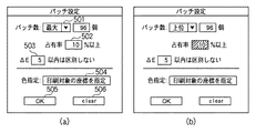
ステップS305において、図5に示す後述のパッチデータ設定画面で校正用パッチ画像データを生成する際の条件を設定する。これらの設定はUI102によって設定され、記憶部105にその内容が保存される。
In step S305, conditions for generating calibration patch image data are set on the patch data setting screen described later shown in FIG. These settings are set by the
ステップS306において、ステップS304で作成された統計データとステップS305で設定されたパッチ生成条件から図7に示す後述の校正用パッチ画像データを生成し、記憶部105にその内容が保存される。このとき動的に生成されたパッチ画像データに対するターゲット値は、ステップS301で設定された印刷対象データの入力色空間からパッチ画像データに使用した値をCIE L*a*b*値に変換して記憶部105にその内容が保存される。
In step S306, calibration patch image data (described later) shown in FIG. 7 is generated from the statistical data created in step S304 and the patch generation conditions set in step S305, and the contents are stored in the
ステップS307において、校正用パッチ画像の印刷が行われる。ステップS301で設定された印刷モードが「通常校正」の場合には予め用意した標準の校正用パッチ画像をそのまま印刷し、「最適校正」の場合にはステップS306で作成した最適校正用のパッチ画像を印刷する。PC101は、生成された校正用パッチデータをプリンタに出力し、プリンタにより校正用パッチを印刷させるよう印刷制御する。
In step S307, a calibration patch image is printed. If the printing mode set in step S301 is “normal calibration”, the standard calibration patch image prepared in advance is printed as it is. If it is “optimal calibration”, the optimal calibration patch image created in step S306 is printed. To print. The
ステップS308において、ステップS307で印刷されたパッチ画像の測色を測色機108で行う。測色した値(測色データ)は記憶部105にその内容が保存される。
In step S308, the
ステップS309において、校正用のLUTの作成を行い、記憶部105にその内容が保存される。ここで作成されたLUTが印刷対象データの印刷を行う際の画像処理中において適用されることで、印刷対象データに最適な校正が行われて印刷される。
In
図4は、本発明に関わる実施形態における校正モード設定画面の例である。この画面はオペレータがUI102によってシステムに印刷処理を指示した際に表示される。401と402は排他的に選択できるようになっており、「通常校正」か「最適校正」かを指定する。
FIG. 4 is an example of a calibration mode setting screen in the embodiment according to the present invention. This screen is displayed when the operator instructs the system to perform print processing through the
403は、印刷対象データの入力元を指定する。入力元は記憶部105又は205、およびデータ入出力部106又は206のどちらでも良い。この設定は図4(b)に示す通り「通常校正」時には無効になる。
404は、印刷対象データの色空間定義を指定する。ここで指定された色空間定義に基づいて印刷対象データの入力信号値をデバイスに依存しない色空間を示すCIE L*a*b*の値に変換する。この設定は403と同様に、図4(b)に示す通り「通常印刷」時には無効になる。
405は、印刷設定を反映させて次の処理に移る時に押されるボタンである。406は印刷を取りやめる際に押されるボタンである。
図5は、本発明に関わる実施形態における校正用パッチ画像生成処理の設定画面の一例である。本実施形態における情報処理装置は、図5に示すようなマンマシンインタフェースによって、校正用パッチの色を指定する。 FIG. 5 is an example of a setting screen for calibration patch image generation processing in the embodiment according to the present invention. The information processing apparatus according to the present embodiment designates the color of the calibration patch using a man-machine interface as shown in FIG.
501と502において生成するパッチの数を指定し、パッチ数の制御には図5(a)および(b)に示す通り「最大」と「上位」の二種類がある。「最大」を指定した場合には、印刷領域内における占有率が高い色を順番にピックアップしていき、ピックアップされた色数が501で指定した数になるか、502で指定した占有率を下回るまでパッチを追加する。「上位」を指定した場合は、占有率の高い色から順に501で指定した個数をピックアップする。このとき、印刷対象データに含まれる色数が指定した個数に満たない場合には指定した色数にならなくてもピックアップを終了する。また、502の設定は図5(b)に示す通り「上位」時には無効になる。 The number of patches generated in 501 and 502 is specified, and there are two types of control of the number of patches, “maximum” and “upper” as shown in FIGS. 5A and 5B. When “Maximum” is specified, colors with a high occupation rate in the print area are picked up in order, and the number of picked up colors becomes the number specified in 501 or less than the occupation rate specified in 502 Add patches until When “upper” is designated, the number designated in 501 is picked up in order from the color with the highest occupation ratio. At this time, if the number of colors included in the print target data is less than the designated number, the pickup is ended even if the designated number of colors is not reached. Also, the setting 502 is invalid when “upper” as shown in FIG.
503はピックアップする際の条件を指定し、占有率の上位から色をピックアップする際に、次の候補がより上位の色と比較してΔEが指定した値以上離れていない場合は、ピックアップ対象から除外されることになる。このときのΔEの算出方法は印刷対象データの値をCIE L*a*b*値に変換した後に、式(1)によって算出される。 503 designates the conditions for picking up, and when picking up the color from the top of the occupation rate, if the next candidate is not more than the designated value compared to the higher order color, it will be removed from the picked up object Will be excluded. The calculation method of ΔE at this time is calculated by the equation (1) after converting the value of the print target data into the CIE L * a * b * value.

504は前述の占有率による自動ピックアップとは別に、オペレータが印刷対象データの座標から直接ピックアップする色を指定するためのボタンである。このボタンを押した際には、後述する図6の画面が開く。
505は上記設定を反映させて次の処理に移る時に押されるボタンである。506は全ての設定を初期値に戻すボタンである。このボタンが押された際には504で指定した色はクリアされる。
Reference numeral 505 denotes a button that is pressed when the above setting is reflected and the process proceeds to the next process.
図6は本発明に関わる実施形態における校正用パッチ画像生成処理の座標によるパッチ色指定画面の例である。 FIG. 6 shows an example of a patch color designation screen based on the coordinates of the calibration patch image generation process in the embodiment according to the present invention.
601は印刷対象データのプレビュー画面である。602は色をピックアップするためのカーソルである。このカーソルをプレビュー画面中の任意の位置に合わせてクリックすると後述する604のリストに座標が追加される。
603は追加された座標を表す印で、後述する604のリストで選択された座標はハイライト表示される。
604は追加された座標を一覧するリストである。追加した順番に番号が振られ、その座標が表示される。
A
605は604で選択した座標を削除するためのボタンである。606は追加を終了して図5のパッチ設定画面に戻るためのボタンである。
図7は本発明に関わる実施形態におけるパッチ画像の例である。図7に示したとおりパッチ画像はパッチとそのパッチ番号で構成されている。パッチの数は図5での設定によって増減する。 FIG. 7 is an example of a patch image in the embodiment according to the present invention. As shown in FIG. 7, the patch image is composed of patches and their patch numbers. The number of patches increases or decreases depending on the setting shown in FIG.
以上のように、本実施形態においては、特定の印刷対象物専用の校正用パッチ画像を動的に作成して印刷する。パッチ画像は印刷物に含まれる色から選択し、そのパッチの入力色情報(CIE L*a*b*やXYZに代表されるの色空間上の座標値)を目標値とする。このパッチ画像を対象のプリンタで印刷し、そのパッチ画像の測定値と目標値をもとに校正を行うことで対象印刷物についての正確な校正を行うことができる。 As described above, in this embodiment, a calibration patch image dedicated to a specific print object is dynamically created and printed. The patch image is selected from the colors included in the printed material, and the input color information of the patch (coordinate values in the color space represented by CIE L * a * b * and XYZ) is used as the target value. By printing this patch image with the target printer and performing calibration based on the measured value and the target value of the patch image, the target printed matter can be accurately calibrated.
本発明には、プログラム(情報処理プログラム)コードの指示に基づき、コンピュータ上で稼働しているオペレーティングシステム(OS)等が実際の処理の一部又は全部を行い、その処理によって前述した実施形態の機能が実現される場合も含まれる。更に、記憶媒体から読み出されたプログラムコードが、コンピュータに挿入された機能拡張カードやコンピュータに接続された機能拡張ユニットに備わるメモリに書込まれた場合についても、本発明は適用される。その場合に、書き込まれたプログラムコードの指示に基づき、その機能拡張カードや機能拡張ユニットに備わるCPU等が実際の処理の一部又は全部を行い、その処理によって前述した実施形態の機能が実現される。 In the present invention, an operating system (OS) or the like running on a computer performs part or all of actual processing based on an instruction of a program (information processing program) code. This includes cases where functions are realized. Furthermore, the present invention is also applied to the case where the program code read from the storage medium is written in a memory provided in a function expansion card inserted into the computer or a function expansion unit connected to the computer. In that case, based on the instruction of the written program code, the CPU or the like provided in the function expansion card or function expansion unit performs part or all of the actual processing, and the functions of the above-described embodiments are realized by the processing. The
101 PC
102 UI
103 CPU
104 作業メモリ
105 記憶部
106 データ入出力部
107 プリンタ
108 測色機
201 演算部
202 UI
203 CPU
204 作業メモリ
205 記憶部
206 データ入出力部
207 プリント部
208 測色機
209 プリンタ
210 ホストPC
101 PC
102 UI
103 CPU
104
203 CPU
204
Claims (5)
前記第1の特定手段により特定された色情報に従ってパッチ画像の色を選択し、プリンタでの印刷結果を校正するための校正用パッチデータを生成する生成手段と、
前記印刷対象の画像データの色空間を指定する指定手段と、
前記校正用パッチデータに含まれる色の前記指定手段により指定された色空間における値から前記校正用パッチデータに含まれる色のデバイスに依存しない色空間における値に変換することにより、前記校正用パッチデータに含まれる色の目標値を特定する第2の特定手段と、
前記生成手段により生成された前記校正用パッチデータに基づき前記プリンタで印刷されたパッチ画像の測色結果を取得する取得手段と、
前記取得手段により取得された測色結果及び前記第2の特定手段により特定された目標値に基づいて、多次元で前記画像データを校正する校正手段と、
を有することを特徴とする情報処理装置。 Analyzing a color included in image data to be printed, and based on a result of the analysis, specifying a color information;
Generating means for selecting a color of the patch image in accordance with the color information specified by the first specifying means, and generating calibration patch data for calibrating the print result of the printer;
Designating means for designating a color space of the image data to be printed;
By converting the color included in the calibration patch data from the value in the color space specified by the specifying unit to the value in the color space independent of the device of the color included in the calibration patch data, the calibration patch A second specifying means for specifying a target value of a color included in the data;
Acquiring means for acquiring a colorimetric result of a patch image printed by the printer based on the calibration patch data generated by the generating means;
Calibration means for calibrating the image data in multi-dimensions based on the colorimetric result obtained by the obtaining means and the target value identified by the second identifying means;
An information processing apparatus comprising:
前記生成手段は、前記占有率に応じた前記校正用パッチデータを生成する、
ことを特徴とする請求項1に記載の情報処理装置。 The first specifying means analyzes an occupation ratio for each color information included in the image data,
The generating means generates the calibration patch data according to the occupation ratio;
The information processing apparatus according to claim 1.
前記第1の特定手段は、前記プレビュー手段により前記表示装置に表示された前記プレビュー画像上でユーザにより指定された位置の色情報を特定する、ことを特徴とする請求項1に記載の情報処理装置。 Preview means for displaying a preview image of the image data on a display device;
2. The information processing according to claim 1, wherein the first specifying unit specifies color information at a position designated by a user on the preview image displayed on the display device by the preview unit. apparatus.
前記第1の特定工程において特定された色情報に従ってパッチ画像の色を選択し、プリンタでの印刷結果を校正するための校正用パッチデータを生成する生成工程と、
前記印刷対象の画像データの色空間を指定する指定工程と、
前記校正用パッチデータに含まれる色の前記指定工程において指定された色空間における値から前記校正用パッチデータに含まれる色のデバイスに依存しない色空間における値に変換することにより、前記校正用パッチデータに含まれる色の目標値を特定する第2の特定工程と、
前記生成工程において生成された前記校正用パッチデータに基づき前記プリンタで印刷されたパッチ画像の測色結果を取得する取得工程と、
前記取得工程において取得された測色結果及び前記第2の特定工程において特定された目標値に基づいて、多次元で前記画像データを校正する校正工程と、
を有することを特徴とする情報処理方法。 Analyzing a color included in image data to be printed, and identifying color information based on a result of the analysis;
A generation step of selecting a color of the patch image in accordance with the color information specified in the first specifying step and generating patch data for calibration for proofreading the printing result by the printer;
A designation step for designating a color space of the image data to be printed;
By converting the color included in the calibration patch data from the value in the color space specified in the specifying step into the value in the color space independent of the device of the color included in the calibration patch data, the calibration patch A second specifying step of specifying a target value of a color included in the data;
An acquisition step of acquiring a color measurement result of a patch image printed by the printer based on the calibration patch data generated in the generation step;
A calibration step for calibrating the image data in multi-dimensions based on the colorimetric result acquired in the acquisition step and the target value specified in the second specification step;
An information processing method characterized by comprising:
Priority Applications (1)
| Application Number | Priority Date | Filing Date | Title |
|---|---|---|---|
| JP2008335219A JP5610687B2 (en) | 2008-12-26 | 2008-12-26 | Information processing apparatus, method, and program |
Applications Claiming Priority (1)
| Application Number | Priority Date | Filing Date | Title |
|---|---|---|---|
| JP2008335219A JP5610687B2 (en) | 2008-12-26 | 2008-12-26 | Information processing apparatus, method, and program |
Publications (3)
| Publication Number | Publication Date |
|---|---|
| JP2010157920A JP2010157920A (en) | 2010-07-15 |
| JP2010157920A5 JP2010157920A5 (en) | 2012-02-16 |
| JP5610687B2 true JP5610687B2 (en) | 2014-10-22 |
Family
ID=42575479
Family Applications (1)
| Application Number | Title | Priority Date | Filing Date |
|---|---|---|---|
| JP2008335219A Active JP5610687B2 (en) | 2008-12-26 | 2008-12-26 | Information processing apparatus, method, and program |
Country Status (1)
| Country | Link |
|---|---|
| JP (1) | JP5610687B2 (en) |
Families Citing this family (4)
| Publication number | Priority date | Publication date | Assignee | Title |
|---|---|---|---|---|
| JP6827704B2 (en) | 2016-03-31 | 2021-02-10 | キヤノン株式会社 | Image forming device and its control method, program |
| JP2022188414A (en) | 2021-06-09 | 2022-12-21 | ブラザー工業株式会社 | Printing device |
| JP2023175403A (en) | 2022-05-30 | 2023-12-12 | ブラザー工業株式会社 | Printer, printing method and printing program |
| JP2024013272A (en) | 2022-07-20 | 2024-02-01 | ブラザー工業株式会社 | Image processing device, control method for image processing device, program, and printing device |
Family Cites Families (3)
| Publication number | Priority date | Publication date | Assignee | Title |
|---|---|---|---|---|
| JP2002118763A (en) * | 2000-10-06 | 2002-04-19 | Ricoh Co Ltd | Color image output method and color image output device |
| JP2005184144A (en) * | 2003-12-16 | 2005-07-07 | Seiko Epson Corp | Color image data correcting method, color image data correcting apparatus, and color correction table generating program |
| JP4873696B2 (en) * | 2006-04-25 | 2012-02-08 | キヤノン株式会社 | Information processing apparatus, method, and program for confirming matching accuracy between printers |
-
2008
- 2008-12-26 JP JP2008335219A patent/JP5610687B2/en active Active
Also Published As
| Publication number | Publication date |
|---|---|
| JP2010157920A (en) | 2010-07-15 |
Similar Documents
| Publication | Publication Date | Title |
|---|---|---|
| JP5153607B2 (en) | Image processing apparatus, image processing method, and image processing program | |
| JP5462756B2 (en) | Color selection support method, color value acquisition method, image processing method, color selection support device, color value acquisition device, image processing device, and program | |
| EP3557857A1 (en) | Color conversion table creation device and method, color conversion device, and program | |
| US7978382B2 (en) | Computer readable medium recording a calibration program, calibration method, and calibration system for detecting patch positions during acquisition of calorimetric values from a patch sheet | |
| JP2002112055A (en) | Color reproduction characteristic display device and color reproduction characteristic display program record medium | |
| US7843605B2 (en) | Color processing apparatus and method thereof | |
| EP2696568A1 (en) | Print color evaluating system and print color evaluating method | |
| US11323579B2 (en) | Image processing apparatus, image processing method, and storage medium | |
| JP5610687B2 (en) | Information processing apparatus, method, and program | |
| JP3990859B2 (en) | Color processing method and apparatus | |
| JP2006094040A (en) | Profile generating device, program, and profile generating method | |
| JP4873696B2 (en) | Information processing apparatus, method, and program for confirming matching accuracy between printers | |
| JP2002112054A (en) | Color reproduction characteristic display device and color reproduction characteristic display program record medium | |
| JP4974030B2 (en) | Image processing apparatus and image processing method | |
| JP2007143077A (en) | Method and apparatus of updating device profile | |
| JP2007205832A (en) | Image data management method for colorimetry, image data management system for colorimetry, and image data management program for colorimetry | |
| JP2008118355A (en) | Image processor and image processing method | |
| JP7321885B2 (en) | Image processing device, image processing method, and program | |
| US20240073350A1 (en) | Information processing apparatus, information processing method, and information processing system | |
| JP2020088709A (en) | Image processing apparatus, image processing method and program | |
| JP7331602B2 (en) | Color conversion table correction device and program | |
| US11523031B2 (en) | Image processing apparatus, control method of image processing apparatus, and storage medium | |
| JP2013222979A (en) | Data processing device, data processing method, and program therefor | |
| JP2006030409A (en) | Device and program for image color display | |
| US8913294B2 (en) | Image processing apparatus and image processing system |
Legal Events
| Date | Code | Title | Description |
|---|---|---|---|
| A521 | Written amendment |
Free format text: JAPANESE INTERMEDIATE CODE: A523 Effective date: 20111221 |
|
| A621 | Written request for application examination |
Free format text: JAPANESE INTERMEDIATE CODE: A621 Effective date: 20111221 |
|
| A977 | Report on retrieval |
Free format text: JAPANESE INTERMEDIATE CODE: A971007 Effective date: 20121030 |
|
| A131 | Notification of reasons for refusal |
Free format text: JAPANESE INTERMEDIATE CODE: A131 Effective date: 20121106 |
|
| A131 | Notification of reasons for refusal |
Free format text: JAPANESE INTERMEDIATE CODE: A131 Effective date: 20130823 |
|
| A521 | Written amendment |
Free format text: JAPANESE INTERMEDIATE CODE: A523 Effective date: 20131022 |
|
| A131 | Notification of reasons for refusal |
Free format text: JAPANESE INTERMEDIATE CODE: A131 Effective date: 20140512 |
|
| A521 | Written amendment |
Free format text: JAPANESE INTERMEDIATE CODE: A523 Effective date: 20140710 |
|
| TRDD | Decision of grant or rejection written | ||
| A01 | Written decision to grant a patent or to grant a registration (utility model) |
Free format text: JAPANESE INTERMEDIATE CODE: A01 Effective date: 20140804 |
|
| A61 | First payment of annual fees (during grant procedure) |
Free format text: JAPANESE INTERMEDIATE CODE: A61 Effective date: 20140902 |
|
| R151 | Written notification of patent or utility model registration |
Ref document number: 5610687 Country of ref document: JP Free format text: JAPANESE INTERMEDIATE CODE: R151 |