JP5580337B2 - Apparatus for creating a reference on a substrate - Google Patents
Apparatus for creating a reference on a substrate Download PDFInfo
- Publication number
- JP5580337B2 JP5580337B2 JP2011544450A JP2011544450A JP5580337B2 JP 5580337 B2 JP5580337 B2 JP 5580337B2 JP 2011544450 A JP2011544450 A JP 2011544450A JP 2011544450 A JP2011544450 A JP 2011544450A JP 5580337 B2 JP5580337 B2 JP 5580337B2
- Authority
- JP
- Japan
- Prior art keywords
- substrate
- reference device
- along
- longitudinal axis
- Prior art date
- Legal status (The legal status is an assumption and is not a legal conclusion. Google has not performed a legal analysis and makes no representation as to the accuracy of the status listed.)
- Expired - Fee Related
Links
Images


Classifications
-
- H—ELECTRICITY
- H05—ELECTRIC TECHNIQUES NOT OTHERWISE PROVIDED FOR
- H05K—PRINTED CIRCUITS; CASINGS OR CONSTRUCTIONAL DETAILS OF ELECTRIC APPARATUS; MANUFACTURE OF ASSEMBLAGES OF ELECTRICAL COMPONENTS
- H05K1/00—Printed circuits
- H05K1/02—Details
- H05K1/0266—Marks, test patterns or identification means
- H05K1/0269—Marks, test patterns or identification means for visual or optical inspection
-
- B—PERFORMING OPERATIONS; TRANSPORTING
- B41—PRINTING; LINING MACHINES; TYPEWRITERS; STAMPS
- B41J—TYPEWRITERS; SELECTIVE PRINTING MECHANISMS, i.e. MECHANISMS PRINTING OTHERWISE THAN FROM A FORME; CORRECTION OF TYPOGRAPHICAL ERRORS
- B41J11/00—Devices or arrangements of selective printing mechanisms, e.g. ink-jet printers or thermal printers, for supporting or handling copy material in sheet or web form
- B41J11/36—Blanking or long feeds; Feeding to a particular line, e.g. by rotation of platen or feed roller
- B41J11/42—Controlling printing material conveyance for accurate alignment of the printing material with the printhead; Print registering
- B41J11/46—Controlling printing material conveyance for accurate alignment of the printing material with the printhead; Print registering by marks or formations on the paper being fed
-
- B—PERFORMING OPERATIONS; TRANSPORTING
- B41—PRINTING; LINING MACHINES; TYPEWRITERS; STAMPS
- B41J—TYPEWRITERS; SELECTIVE PRINTING MECHANISMS, i.e. MECHANISMS PRINTING OTHERWISE THAN FROM A FORME; CORRECTION OF TYPOGRAPHICAL ERRORS
- B41J3/00—Typewriters or selective printing or marking mechanisms characterised by the purpose for which they are constructed
- B41J3/54—Typewriters or selective printing or marking mechanisms characterised by the purpose for which they are constructed with two or more sets of type or printing elements
- B41J3/543—Typewriters or selective printing or marking mechanisms characterised by the purpose for which they are constructed with two or more sets of type or printing elements with multiple inkjet print heads
-
- H—ELECTRICITY
- H05—ELECTRIC TECHNIQUES NOT OTHERWISE PROVIDED FOR
- H05K—PRINTED CIRCUITS; CASINGS OR CONSTRUCTIONAL DETAILS OF ELECTRIC APPARATUS; MANUFACTURE OF ASSEMBLAGES OF ELECTRICAL COMPONENTS
- H05K2201/00—Indexing scheme relating to printed circuits covered by H05K1/00
- H05K2201/09—Shape and layout
- H05K2201/09818—Shape or layout details not covered by a single group of H05K2201/09009 - H05K2201/09809
- H05K2201/09918—Optically detected marks used for aligning tool relative to the PCB, e.g. for mounting of components
-
- H—ELECTRICITY
- H05—ELECTRIC TECHNIQUES NOT OTHERWISE PROVIDED FOR
- H05K—PRINTED CIRCUITS; CASINGS OR CONSTRUCTIONAL DETAILS OF ELECTRIC APPARATUS; MANUFACTURE OF ASSEMBLAGES OF ELECTRICAL COMPONENTS
- H05K2203/00—Indexing scheme relating to apparatus or processes for manufacturing printed circuits covered by H05K3/00
- H05K2203/01—Tools for processing; Objects used during processing
- H05K2203/0104—Tools for processing; Objects used during processing for patterning or coating
- H05K2203/013—Inkjet printing, e.g. for printing insulating material or resist
-
- H—ELECTRICITY
- H05—ELECTRIC TECHNIQUES NOT OTHERWISE PROVIDED FOR
- H05K—PRINTED CIRCUITS; CASINGS OR CONSTRUCTIONAL DETAILS OF ELECTRIC APPARATUS; MANUFACTURE OF ASSEMBLAGES OF ELECTRICAL COMPONENTS
- H05K2203/00—Indexing scheme relating to apparatus or processes for manufacturing printed circuits covered by H05K3/00
- H05K2203/10—Using electric, magnetic and electromagnetic fields; Using laser light
- H05K2203/107—Using laser light
-
- H—ELECTRICITY
- H05—ELECTRIC TECHNIQUES NOT OTHERWISE PROVIDED FOR
- H05K—PRINTED CIRCUITS; CASINGS OR CONSTRUCTIONAL DETAILS OF ELECTRIC APPARATUS; MANUFACTURE OF ASSEMBLAGES OF ELECTRICAL COMPONENTS
- H05K2203/00—Indexing scheme relating to apparatus or processes for manufacturing printed circuits covered by H05K3/00
- H05K2203/15—Position of the PCB during processing
- H05K2203/1545—Continuous processing, i.e. involving rolls moving a band-like or solid carrier along a continuous production path
-
- H—ELECTRICITY
- H05—ELECTRIC TECHNIQUES NOT OTHERWISE PROVIDED FOR
- H05K—PRINTED CIRCUITS; CASINGS OR CONSTRUCTIONAL DETAILS OF ELECTRIC APPARATUS; MANUFACTURE OF ASSEMBLAGES OF ELECTRICAL COMPONENTS
- H05K3/00—Apparatus or processes for manufacturing printed circuits
- H05K3/0073—Masks not provided for in groups H05K3/02 - H05K3/46, e.g. for photomechanical production of patterned surfaces
- H05K3/0082—Masks not provided for in groups H05K3/02 - H05K3/46, e.g. for photomechanical production of patterned surfaces characterised by the exposure method of radiation-sensitive masks
-
- Y—GENERAL TAGGING OF NEW TECHNOLOGICAL DEVELOPMENTS; GENERAL TAGGING OF CROSS-SECTIONAL TECHNOLOGIES SPANNING OVER SEVERAL SECTIONS OF THE IPC; TECHNICAL SUBJECTS COVERED BY FORMER USPC CROSS-REFERENCE ART COLLECTIONS [XRACs] AND DIGESTS
- Y10—TECHNICAL SUBJECTS COVERED BY FORMER USPC
- Y10T—TECHNICAL SUBJECTS COVERED BY FORMER US CLASSIFICATION
- Y10T83/00—Cutting
- Y10T83/02—Other than completely through work thickness
- Y10T83/0333—Scoring
Description
本発明は、基材上に実質的に連続的な部分を有する基準を作製するための手法に関する。基準は基材の位置を決定するために使用することができる。 The present invention relates to a technique for creating a reference having a substantially continuous portion on a substrate. The criteria can be used to determine the position of the substrate.
可撓性の電子的又は光学的構成要素を含む、多くの物品の製造は、細長い基材又はウェブ上に配置又は形成された層間の位置合わせを含む。ウェブ上の材料層の形成は、連続的なプロセス又は複数の工程を含んだステップアンドリピートプロセスで実施することができる。例えば、材料のパターンは、複数の堆積工程を通じて、ウェブ等の細長い基材上の層中に堆積され、層状の電子的又は光学的装置を形成することができる。いくつかの物品は、基材の一方の側又は両側に施される特徴の正確な位置合わせを必要とする。 The manufacture of many articles, including flexible electronic or optical components, involves alignment between layers disposed or formed on an elongated substrate or web. Formation of the material layer on the web can be performed in a continuous process or a step-and-repeat process including multiple steps. For example, the pattern of material can be deposited in a layer on an elongated substrate, such as a web, through a plurality of deposition processes to form a layered electronic or optical device. Some articles require precise alignment of features applied to one or both sides of the substrate.
層間の正確な位置合わせを実現するため、基材が複数の製造工程を通じて移動する際に、横方向(クロスウェブ)の位置決め、及び長手方向(ダウンウェブ)の位置決めが維持されなくてはならない。基材上に形成される層間の位置合わせの維持は、基材が可撓性又は伸縮性である場合に、より複雑となる。いくつかの物品は複数の工程で作製され、工程中に、材料又はプロセスが基材に順に施され、プロセス工程のそれぞれに正確な位置合わせが求められる。 In order to achieve accurate alignment between layers, lateral (crossweb) positioning and longitudinal (downweb) positioning must be maintained as the substrate moves through multiple manufacturing steps. Maintaining alignment between the layers formed on the substrate becomes more complex when the substrate is flexible or stretchable. Some articles are made in multiple steps, during which the material or process is sequentially applied to the substrate, and each process step requires precise alignment.
基準は、様々な製造工程を通じて、基材が移動するとき、その上に形成される物品と共に、基材位置の決定に使用することができる基材の配向特徴である。基材位置の検知を向上させるために、基材の基準から得られる解像度を高めることは望ましい。製造を単純化し、コストを削減し、及び/又は基材位置の検知の解像度を高める、基材上に基準を作製するための向上した方法及びシステムの必要性がある。本発明は、これら及びその他の要求を満たし、先行技術に勝る他の利点を提供する。 A criterion is an orientation characteristic of a substrate that can be used to determine the substrate position along with the articles formed thereon as the substrate moves through various manufacturing processes. In order to improve the detection of the substrate position, it is desirable to increase the resolution obtained from the substrate reference. There is a need for an improved method and system for creating a reference on a substrate that simplifies manufacturing, reduces costs, and / or increases the resolution of substrate position sensing. The present invention fulfills these and other needs and provides other advantages over the prior art.
本発明の実施形態は、基材上に基準を作製するように構成される装置を目的とする。第1の基準デバイスは基材上に1つの基準を作製し、第2の基準デバイスは基材上に別の基準を作製する。第1の基準デバイス及び第2の基準デバイスによって作製された基準はそれぞれ、基材の長手方向軸に対して有限でゼロでない傾斜を備えた少なくとも1つの連続的な部分を有する。 Embodiments of the present invention are directed to an apparatus configured to produce a reference on a substrate. The first reference device creates one reference on the substrate and the second reference device creates another reference on the substrate. Each reference created by the first reference device and the second reference device has at least one continuous portion with a finite and non-zero slope relative to the longitudinal axis of the substrate.
移動機構は、長手方向軸に沿って、基材と第1の基準デバイス及び第2の基準デバイスとの間に相対運動を提供する。第1の基準デバイス及び第2の基準デバイスは連結され、アクチュエータが、横方向軸の構成要素を有する軌道に沿って、第1の基準デバイス及び第2の基準デバイスを共に往復移動させる。軌道に沿った第1の基準デバイス及び第2の基準デバイスの移動中、並びに長手方向軸に沿った相対運動中に、第1の基準デバイスは基材上に1つの基準を作製するために動作し、第2の基準デバイスは基材上に別の基準を作製するために動作する。 The movement mechanism provides relative movement between the substrate and the first reference device and the second reference device along the longitudinal axis. The first reference device and the second reference device are coupled, and an actuator reciprocates the first reference device and the second reference device together along a trajectory having a transverse axis component. During movement of the first reference device and the second reference device along the trajectory, and during relative movement along the longitudinal axis, the first reference device operates to create a reference on the substrate. The second reference device then operates to create another reference on the substrate.
別の実施形態は、基材上に基準を印刷するように構成された装置を含む。装置は、インクを射出して第1の基準を印刷する第1の印字開口を含む。第2の印字開口は、インクを射出して第2の基準を印刷する。移動機構は、基材の長手方向軸に沿って、基材と第1の印字開口及び第2の印字開口との間に相対運動を提供する。アクチュエータは、少なくとも1つの横方向軸の構成要素を有する軌道に沿って、第1の印字開口及び第2の印字開口を共に往復移動させる。軌道に沿った第1の印字開口及び第2の印字開口の移動中、並びに長手方向軸に沿った第1の印字開口及び第2の印字開口と基材との間の相対運動中に、第1の印字開口は、基材上に1つの基準を印刷し、第2の印字開口は、基材上に別の基準を印刷する。 Another embodiment includes an apparatus configured to print a reference on a substrate. The apparatus includes a first print opening that ejects ink to print a first reference. The second printing opening ejects ink to print the second reference. The moving mechanism provides relative movement between the substrate and the first print opening and the second print opening along the longitudinal axis of the substrate. The actuator reciprocates both the first print opening and the second print opening along a track having at least one transverse axis component. During movement of the first and second print openings along the trajectory and during relative movement between the first and second print openings and the substrate along the longitudinal axis, One print opening prints one reference on the substrate and the second print opening prints another reference on the substrate.
更に別の実施形態は、長手方向軸及び横方向軸を有する基材上に基準を作製する方法を目的とする。第1の基準デバイス及び第2の基準デバイスは、横方向軸に沿って構成要素を有する軌道に沿って共に往復移動し、基材並びに第1の基準デバイス及び第2の基準デバイスは、長手方向軸に沿って相対運動をする。第1の基準デバイスは、軌道に沿った移動中、及び長手方向軸に沿った相対運動中に、基材上に1つの基準を作製するために動作する。第2の基準デバイスは、軌道に沿った移動中、及び相対運動中に、基材上に別の基準を作製するために動作する。 Yet another embodiment is directed to a method of creating a reference on a substrate having a longitudinal axis and a transverse axis. The first reference device and the second reference device reciprocate together along a trajectory having components along the transverse axis, and the substrate and the first reference device and the second reference device are longitudinal. Make relative motion along the axis. The first reference device operates to create a reference on the substrate during movement along the trajectory and during relative movement along the longitudinal axis. The second reference device operates to create another reference on the substrate during movement along the trajectory and during relative movement.
上記の本発明の概要は、本発明のそれぞれの実施形態又は全ての実現形態を説明することを意図したものではない。本発明の利点及び効果、並びに本発明に対する更なる理解は、以下に記載する発明を実施するための形態及び特許請求の範囲を添付図面と併せて参照することによって明らかになり、理解するに至るであろう。 The above summary of the present invention is not intended to describe each embodiment or every implementation of the present invention. Advantages and advantages of the present invention, as well as a further understanding of the present invention, will become apparent and understood by referring to the following detailed description and claims in conjunction with the accompanying drawings. Will.
本発明は様々な変更例及び代替形状が可能であるが、その具体例を一例として図面に示すと共に詳細に説明する。ただし、本発明は記載される特定の実施形態に限定されるものではないことを理解されたい。逆に、添付の請求の範囲に記載した発明の範囲を逸脱することなく、あらゆる変更、均等物、及び代替物が含まれることを意図している。 While various modifications and alternative shapes are possible for the present invention, specific examples thereof are shown in the drawings as examples and will be described in detail. However, it should be understood that the invention is not limited to the specific embodiments described. On the contrary, the intention is to cover all modifications, equivalents, and alternatives without departing from the scope of the invention as set forth in the appended claims.
例示した実施形態の以下の説明において、その一部を生成させ、実例として示される添付図面、発明を実施できる種々の実施形態を参照する。本発明の範囲から逸脱することなく、他の実施形態が利用されてもよく、かつ構造的変更が行われてもよいことは理解されるであろう。 In the following description of the illustrated embodiments, reference will be made to various embodiments in which a portion thereof may be generated and shown in the accompanying drawings and in which the invention may be practiced by way of example. It will be understood that other embodiments may be utilized and structural changes may be made without departing from the scope of the invention.
本発明の実施形態は、基材位置の検知の解像度を向上させる、基材上に基準を形成する方法及びシステムを例示する。例えば、本明細書で説明する基準は、ロール・ツー・ロール製造プロセスの間に基材ウェブ上に堆積される、複数の材料の層の間の整合を容易にするために使用され得る。 Embodiments of the present invention illustrate a method and system for forming a reference on a substrate that improves the resolution of substrate position detection. For example, the criteria described herein can be used to facilitate alignment between multiple layers of material deposited on a substrate web during a roll-to-roll manufacturing process.
いくつかの従来の手法では、定規上のマークに類似する一連の別個の基準マークを含む基準は、基材の軸に沿って配置される。これらの別個のマークは次に、軸に沿って基材位置を決定するために使用される。しかしながら、このタイプの基準は、基準マークにおける断続的な位置検出のみを提供することができ、別個の基準マークの間隔中の位置情報を提供しない。本明細書で説明する様々な実施形態によって例示される基準マークは、実質的に連続的な又は区分的に連続的な基準要素、すなわち、実質的に連続的な部分を有する基準を含み、連続的な位置の更新情報及びより正確な基材の位置決めを提供するために使用され得る。 In some conventional approaches, a fiducial that includes a series of separate fiducial marks that are similar to the marks on a ruler is placed along the axis of the substrate. These separate marks are then used to determine the substrate position along the axis. However, this type of fiducial can only provide intermittent position detection at the fiducial mark and does not provide position information during the distance of the separate fiducial marks. Reference marks, exemplified by various embodiments described herein, include substantially continuous or piecewise continuous reference elements, i.e., references that have a substantially continuous portion, and are continuous. Position update information and can be used to provide more accurate substrate positioning.
図1は、本発明の実施形態による、基材100上に基準を作製するための装置のブロック図である。基材100は、任意の好適な材料で作製されてもよく、剛性、又は可撓性であってもよい。基材100の横方向軸101及び長手方向軸102が、参照のために図1に示される。装置は、基材100上に1つの基準111を作製するように構成される第1の基準デバイス110、及び基材100上に別の基準121を作製するように構成される第2の基準装置120を少なくとも含む。第1の基準デバイス110の動作は、第1の基準制御モジュール115によって制御される。第2の基準デバイス120の動作は、第2の基準制御モジュール125によって制御される。基準デバイス110、120は、基材上に基準を作製することができる任意のタイプの装置を含み得る。例えば、基準デバイスは、基準111、121を、インクジェット印刷、レーザー印刷、レーザースクライビング、機械的スクライビング、直接接触印刷、レーザーアブレーション、及び/又は他の技術によって作製することができる。
FIG. 1 is a block diagram of an apparatus for creating a reference on a
第1の基準デバイス110及び第2の基準デバイス120は、連結部材130で連結され、基材100の上方に第1の基準デバイス110及び第2の基準デバイス120を懸吊する等で、基材100の表面に相対的に配置される。アクチュエータ140は、少なくとも横方向軸101の構成要素を有する軌道150に沿って、基材100の表面を横切って基準デバイス110、120を共に往復移動させる。アクチュエータ制御モジュール160は、アナログ及び/又はデジタル回路を含んでもよく、及び/又はアクチュエータ140の動作を制御し、したがって、第1の基準110及び第2の基準120の軌道150に沿った移動を制御する、ハードウェア又はソフトウェアを実装するプロセッサを含んでもよい。基準デバイス110、120の往復移動の周波数は、一定であってもよく、又は一定でなくてもよく、及び/又は別個の工程で行われてもよい。特に有用な1つの実現形態は、第1の基準デバイス110及び第2の基準デバイス120の、長手方向軸に対して実質的に一定の空間周波数で、軌道150に沿った往復移動である。この実現形態で、長手方向軸102に沿って、第1の基準デバイス110及び第2の基準デバイス120に対する基材100の移動が、実質的に、空間的に一定の場合、得られる基準111、121は正弦波形状であり、図1に例示されるように、基材の長手方向軸に対して実質的に一定の空間周波数を有する。基材の速度が実質的に一定の場合、一定の空間周波数を有する基準は、一定周波数の基準センサ信号の生成に使用することができる。
The
基準作製装置は、基材の長手方向軸102に沿って、基材100と第1の基準デバイス110及び第2の基準デバイス120との間に相対運動を提供するように構成される機構170を更に含む。いくつかの実現形態では、相対運動は、第1の基準デバイス110及び第2の基準デバイス120を移動させることで提供されるのに対し、いくつかの実現形態では、相対運動は、基材100を移動させることで提供される。例えば、長手方向に移動する機構170は、移動可能なテーブル又は回転ドラムを備えてもよい。
The reference fabrication apparatus includes a
長手方向に移動する機構170の動作は、制御モジュール180によって制御され、そのモジュールは、電子式であってもよく、アクチュエータ140及び基材100の移動を調整するためにアクチュエータの移動制御モジュール160に連結されてもよい。フィードバックは移動誤差の低減に使用することができる。
The operation of the longitudinally moving
図1の基準作製装置は、基材100上に2つの基準111、121を作製するように構成されるが、必要に応じて追加の基準を作製するために追加の基準デバイスが使用されてもよい。基準はそれぞれ、1つの基準デバイスによって別個に作製される。図1に示される実施例では、第1の基準デバイス110は1つの基準111を作製するために動作し、第2の基準デバイス120は別の基準121を作製するために動作する。基準111、121はそれぞれ、基準111、121の傾斜が長手方向軸に対して有限でゼロでない区域を概して有する。
The reference creation apparatus of FIG. 1 is configured to create two
傾斜した区域を有する基準は、例えば、定規タイプのマークなどの基材に沿って長手方向に走る一連の別個の基準要素より多くの位置情報を提供するので、有利である。別個の基準マークは典型的には、別個のマークのそれぞれにおいてのみ位置情報を提供し、別個の基準マーク間の追加の位置情報を提供しない。したがって、一連の別個の定規タイプのマークである基準の解像度は、マーク間の距離によって制御される。これとは対照的に、連続的で傾斜した区域を有する基準に対して、基準の解像度は別個のマーク間の距離によって制約されない。基準の形状が既知である場合、検出された形状は、連続的な位置情報の提供に使用することができるので、基材位置の検知の解像度を高める。 A reference having an inclined area is advantageous because it provides more positional information than a series of separate reference elements that run longitudinally along a substrate, such as, for example, a ruler type mark. Separate reference marks typically provide position information only in each of the separate marks and do not provide additional position information between separate reference marks. Thus, the resolution of the reference, which is a series of separate ruler type marks, is controlled by the distance between the marks. In contrast, for a reference having a continuous, sloping area, the reference resolution is not constrained by the distance between the separate marks. If the reference shape is known, the detected shape can be used to provide continuous position information, thus increasing the resolution of substrate position detection.
図2のフローチャートは、本発明の実施形態による基準を作製する方法を説明する。第1の基準デバイス及び第2の基準デバイスを、少なくとも1つの横方向軸の構成要素を有する軌道に沿って基材を横切って共に移動する210。基材の長手方向軸に沿って、第1の基準及び第2の基準と基材との間に相対運動を提供する220。第1の基準デバイスを、基材上に1つの基準を作製するために、基材と第1の基準デバイス及び第2の基準デバイスとの間の軌道に沿った移動中、並びに相対運動中に、動作させる230。第2の基準デバイスを、基材上に別の基準を作製するために、基材と第1の基準デバイス及び第2の基準デバイスとの間の軌道に沿った移動中、並びに相対運動中に、動作させる240。第1の基準及び第2の基準はそれぞれ、基準の傾斜が長手方向軸に対して有限でゼロでない区域を有する。
The flowchart of FIG. 2 illustrates a method for creating a reference according to an embodiment of the present invention. A first reference device and a second reference device are moved 210 across the substrate along a trajectory having at least one transverse axis component. A
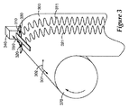
図3は、本発明の実施形態による回転ドラム上に拘束される可撓性ウェブを備える、基材上に基準を作製するための装置の図を例示する。この実施形態では、基材は可撓性で細長いウェブ300である。ウェブ300の横方向軸301及び長手方向軸302の配向が、参照のために示される。ウェブ300はドラム370上に拘束され、例えばロール・ツー・ロールプロセス中のウェブ300上での基準311、321の作製のプロセスを容易にする。第1の基準デバイス310及び第2の基準デバイス320は、連結部材330で連結され、ウェブ300の上方に懸吊される。ドラム370によるウェブ300の回転は、ウェブの長手方向軸302に沿って、基準デバイス310、320とウェブ300との間に相対運動を提供する。アクチュエータ340は、ウェブ300の横方向軸301と実質的に平行である軌道350に沿って、第1の基準デバイス310及び第2の基準デバイス320を共に移動させる。第1の基準デバイス310はウェブ300上に1つの基準311を作製するために動作し、第2の基準デバイス320はウェブ300上に別の基準321を作製するために動作する。
FIG. 3 illustrates an illustration of an apparatus for creating a fiducial on a substrate comprising a flexible web constrained on a rotating drum according to an embodiment of the present invention. In this embodiment, the substrate is a flexible,
ドラム370の回転は、ドラム制御機構(図示せず)によって制御される。アクチュエータ340の動き、及び/又はドラム370の回転は、ドラム回転の速度、及び/又はアクチュエータ動作をプログラムする柔軟性を容易にするように、コンピュータ制御されてもよい。フィードバックは動作、及び/又は回転の制御をサポートするために使用されてもよい。
The rotation of the
いくつかの実施形態では、基準デバイスはインクジェット印字開口を備え、それを通してインクが基材の上に射出されて基準が作製される。図4に例示されるように、基準460、461の作製に使用されるインクジェット開口410、420は、インクジェット開口410、420を共に連結する連結部材として機能するインクジェット印字ヘッド430上に離間して配置されてもよい。第1の開口410は基材上に1つの基準461を作製するために使用され、第2の開口420は基材上に別の基準460を作製するために使用される。第1の開口410及び第2の開口420はそれぞれ、独立して制御されてもよい。一実現形態では、インクジェット開口410、420は、実質的に一定速度でドロップを射出するように制御される。十分な解像度を備えた、得られる基準460、461は滑らかで連続的であり、比較可能なスケールで基準に印刷されるラスタスキャンに比べて著しい改善が見られる。1つ以上の追加の基準は、1つ以上の追加のインクジェット開口をそれぞれ使用して作製することができる。
In some embodiments, the reference device comprises an inkjet print aperture through which ink is ejected onto the substrate to create a reference. As illustrated in FIG. 4, the
正弦波形状等の連続的で周期的な基準が作製される場合、インクジェット印字ヘッド430と基材の横方向軸との間の角度θは、基準間の位相シフトを決定する。例えば、θがゼロで、かつ第1の基準デバイス及び第2の基準デバイスの軌道が基材の横方向軸と実質的に平行である場合、2つの基準は同じ周波数及び位相で作製される。
When a continuous and periodic reference is created, such as a sinusoidal shape, the angle θ between the
いくつかの実施では、位相がずれている周期的な基準を生成することが有利な場合がある。正弦基準及び余弦基準等の、位相がずれている2つの周期的な基準の使用は、冗長情報を提供し、単一の基準よりも高い雑音排除性、精度、及び解像度が得られる。図4は、位相がずれている2つの周期的な基準460、461を生成するために使用することができる構成を例示する。θがゼロでないように、インクジェット印字ヘッド430を傾斜させる。インクジェット開口410、420が実質的に一定速度でインクを射出しているときに、基材の横方向軸と実質的に平行である軌道450に沿ってインクジェット開口410、420が移動することで、位相がずれている周期的な基準460、461を生成する。
In some implementations, it may be advantageous to generate periodic references that are out of phase. The use of two periodic references that are out of phase, such as a sine reference and a cosine reference, provides redundant information and provides higher noise immunity, accuracy, and resolution than a single reference. FIG. 4 illustrates a configuration that can be used to generate two
一実現形態では、第1のインクジェット印字開口410は正弦基準を印刷するために動作し、第2のインクジェット印字開口420は余弦基準を印刷するために動作する。余弦基準を印刷する第2のインクジェット開口420となるθ度の角度は、第1のインクジェット開口410によって印刷される正弦基準から90度ほどシフトした位相であり、次の等式を使用して計算することができる。
In one implementation, the first

式中、Psは、正弦波形状の基準の周期であり、Djは、第1の開口と第2の開口との間の距離である。 In the equation, P s is a reference period of a sinusoidal shape, and D j is a distance between the first opening and the second opening.
基材が可撓性である場合、基準の作製中に基材を拘束することは、基材のひずみによって生じる誤差を低減する。例えば、図3に例示されるように、可撓性ウェブ基材は回転ドラム上に拘束されてもよい。ドラム上に拘束されたウェブは、基準デバイスを、例えば、図4の印字ヘッドのように、ドラムの軸と実質的に平行に配向させることは有利な場合がある。印字ヘッドがロールと実質的に平行でない場合、インクジェットのドロップが移動しなければならない距離は、開口の位置によって変動する。2つのインクジェット開口間の移動距離におけるこの変動は、基準間の位相差を変える。 If the substrate is flexible, constraining the substrate during reference fabrication reduces errors caused by substrate distortion. For example, as illustrated in FIG. 3, the flexible web substrate may be constrained on a rotating drum. It may be advantageous for the web constrained on the drum to orient the reference device substantially parallel to the axis of the drum, such as the printhead of FIG. If the print head is not substantially parallel to the roll, the distance that the inkjet drop must travel varies with the position of the opening. This variation in the travel distance between the two inkjet openings changes the phase difference between the references.
正弦基準及び余弦基準は、最大解像度を得るためにスケーリングされてもよい。例えば、基準の振幅を、横方向位置の誤差に備えていくらかのマージンをもたせて、基材位置決めセンサの画像視界内で基準を最大化するようにできるだけ大きくしてもよい。長手方向のスケーリングは、予測される動作速度に基づいて選択されてよい。正弦基準及び余弦基準のより鋭いピッチ(より高い周波数及びより小さいピークとピークの距離)は、より急な傾斜、及び長手方向のより高い解像度をもたらす。過度に高いピッチは、信号対雑音比を低下させることができ、基材を位置決めるための基準の検出に使用されるセンサの必要なサンプリングレートを上げることもできる。 The sine and cosine criteria may be scaled to obtain maximum resolution. For example, the reference amplitude may be made as large as possible to maximize the reference within the image field of the substrate positioning sensor, with some margin in preparation for lateral position errors. Longitudinal scaling may be selected based on the expected operating speed. Sharper pitches of sine and cosine standards (higher frequency and smaller peak-to-peak distance) result in steeper slopes and higher longitudinal resolution. An excessively high pitch can reduce the signal-to-noise ratio and can also increase the required sampling rate of the sensor used to detect the reference for positioning the substrate.
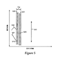
図5は、基材上のインクジェット印刷基準560の別の実施形態を例示する。図5に描かれた実現形態は、2つの印字ヘッド530、531を使用する。第1の開口510及び第2の開口520が基材を横切って共に移動するように、印字ヘッド530、531は連結される。任意の開口が印字ヘッド530、531から選択されてもよい。第1の印字ヘッド530から選択された開口510は、基材上に1つの基準561を印刷し、第2の印字ヘッド531から選択された開口520は別の基準560を印刷する。基準561、560が互いに位相がずれるように、第1の開口510及び第2の開口520は離間して配置されてもよい。基準561と560との間の位相差は、印字開口510と520との間のダウンウェブ距離、Dwによって決定される。
FIG. 5 illustrates another embodiment of an
本明細書で説明する基準は、上記でより詳細に説明されたようにインクジェット印刷を含む、様々なプロセスによって作製されてもよい。図1〜5に関して上述の手法は、他のプロセスで基準を作製するように応用されてもよい。例えば、正弦波形状の位相がシフトした基準を得るために、図4及び5に示す基準デバイス(インクジェット開口)の配向は、直接接触印刷、レーザー印刷、レーザーマーキング、レーザースクライビング、フォトリソグラフィープロセス、アブレーション、機械的スクライビング、及び/又は基準作製可能な他のプロセス等の他のタイプの基準作製プロセスに応用されてもよい。滑らかで周期的な基準を作製するように、基準デバイスが基準の単位面積当たり実質的に一定したエネルギーで動作するように制御されてもよい。基材上に作製される基準のすべては、同じタイプのプロセスによって作製される必要はない。1つ以上の第1の基準は、第1のプロセス、例えば、インクジェット印刷を使用して作製されてもよく、1つ以上の第2の基準は、第2のプロセス、例えば、レーザースクライビングを使用して作製されてもよい。 The criteria described herein may be made by a variety of processes, including ink jet printing as described in more detail above. The techniques described above with respect to FIGS. 1-5 may be applied to create a reference in other processes. For example, to obtain a sinusoidal phase shifted reference, the orientation of the reference device (inkjet aperture) shown in FIGS. 4 and 5 can be direct contact printing, laser printing, laser marking, laser scribing, photolithography process, ablation May be applied to other types of reference fabrication processes, such as mechanical scribing and / or other processes capable of reference fabrication. The reference device may be controlled to operate at a substantially constant energy per unit area of the reference so as to create a smooth and periodic reference. All of the criteria made on the substrate need not be made by the same type of process. The one or more first criteria may be made using a first process, eg, ink jet printing, and the one or more second criteria use a second process, eg, laser scribing. May be produced.
図1〜5の実施例は2つの基準デバイスを使用する様々な構成を例示するが、多数の基準を作製するために、任意の数の基準デバイスが、上述したように連結され、共に移動されてもよい。いくつかの実現形態では、第1の基準デバイス及び第2の基準デバイスに連結されていない追加の基準デバイスを使用して、基材上に1つ以上の追加の基準を形成することが望ましい。例えば、追加の基準は、基材に横方向の位置情報を提供するように、基材又は基材縁部の長手方向軸と実質的に平行である線を含んでもよい。基材を横方向に位置決めるために使用されてもよい方法及びシステムを説明する米国特許第7,296,717号は、参照により本明細書に組み込まれる。 While the example of FIGS. 1-5 illustrates various configurations using two reference devices, any number of reference devices can be joined and moved together as described above to create multiple references. May be. In some implementations, it may be desirable to form one or more additional references on the substrate using additional reference devices that are not coupled to the first reference device and the second reference device. For example, the additional criteria may include a line that is substantially parallel to the longitudinal axis of the substrate or substrate edge so as to provide lateral position information to the substrate. US Pat. No. 7,296,717, which describes a method and system that may be used to laterally position a substrate, is incorporated herein by reference.
図6は、上記で図1に関して例示し説明したように、第1の基準111及び第2の基準121を作製するように構成される装置を例示する。追加の基準デバイス610は、基材100に対して配向され、追加の基準611を作製する。追加の基準デバイス610は、第1の基準デバイス110及び第2の基準デバイス120に連結される必要はない。例えば、追加の基準デバイス610は、横方向軸101に対して実質的に静止していてもよい。追加の基準デバイス610は、上述の基準デバイス、例えば、インクジェット開口、フォトリソグラフィーマスク、レーザープリンター、レーザースクライブ、機械的スクライブ、直接接触ペン、のいずれかを備えてもよい。基材の横方向の位置決め用に、追加の基準611は図6に例示されるように線を含んでもよい。あるいは、追加の基準611は、周期的、非周期的、連続的又は個別等の任意の形状で作製されてもよい。追加の基準611は、第1の基準111及び第2の基準121と同じパス中に作製される必要はなく、第1の基準111及び第2の基準121の作製前又は作製後のいずれかに、異なるパスで作製されてもよい。
FIG. 6 illustrates an apparatus configured to create a
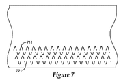
図7及び8は、本明細書で説明するプロセスを使用して作製されてもよい基準を更に例示する。図7及び8に例示するような区分的に連続的な基準は、連続的なマークが基材の一部を切断するような基材に空隙を生成する、アブレーション等の基準方法に、特に有用である。これらの基準の実施例のそれぞれは、基材の長手方向軸に対して有限でゼロでない傾斜を有する実質的に連続的な部分を含む。図7及び8に例示するような区分的に連続的な基準は、軌道に沿って基材を横断する選択された部分の間に基準の作製を中断するように、基準デバイスの動作を制御することによって作製されてもよい。基準711及び721の作製に使用される基準デバイスのそれぞれの動作は、基材上の基準の作製を中断して区分的に連続的なパターンを作成するように、独立して制御されてもよい。図7は、区分的に連続的な正弦基準711及び余弦基準721を例示する。
7 and 8 further illustrate criteria that may be made using the processes described herein. Piecewise continuous criteria such as illustrated in FIGS. 7 and 8 are particularly useful for reference methods such as ablation where continuous marks create voids in the substrate such that a portion of the substrate is cut. It is. Each of these reference embodiments includes a substantially continuous portion having a finite and non-zero slope with respect to the longitudinal axis of the substrate. A piecewise continuous reference as illustrated in FIGS. 7 and 8 controls the operation of the reference device to interrupt the creation of the reference during selected portions that traverse the substrate along the trajectory. May be produced. The operation of each of the reference devices used to create the
図8は、基材を横切って共に移動する連結された第1の基準デバイス及び第2の基準デバイスを使用して作製することができる別の構成を例示する。この実施例では、第1の基準デバイスは、第1の周波数を有する第1の基準811を作製するために、基材を横切るサイクルごとの一部分の間に動作可能であるのに対して、第2の基準デバイスは、基材を横切る5回目ごとのサイクルの間にのみ動作して、第2の周波数を有する第2の基準821を作製する。
FIG. 8 illustrates another configuration that can be made using a coupled first reference device and a second reference device that move together across the substrate. In this example, the first reference device is operable during a portion of every cycle across the substrate to produce a first reference 811 having a first frequency, whereas The second reference device operates only during every fifth cycle across the substrate to create a
いくつかの用途では、基材位置を決定するために、別個の基準及び実質的に連続的な基準の両方を使用することは有利である。図9は、基材に沿った1回のパスで実質的に連続的な基準960、961及び別個の基準970の両方の印刷に使用されてもよい構成を例示する。図9に例示する印字ヘッド930は、図4の構成に類似して、基材の横方向軸に対して角度θ度で傾斜している。連続的な基準961、960の作製に使用されるインクジェット開口910、920は、インクジェット開口910、920を連結する連結部材として機能するインクジェット印字ヘッド930に離間して配置される。第1の開口910は、基材上に1つの基準961を作製するために使用され、第2の開口920は、基材上に別の基準960を作製するために使用される。
In some applications, it is advantageous to use both a separate criterion and a substantially continuous criterion to determine the substrate position. FIG. 9 illustrates a configuration that may be used to print both substantially
第1の開口910及び第2の開口920のそれぞれは、実質的に連続的な基準961、960を生成するようにドロップを射出するように制御される。1つ以上の追加の印字開口975は断続的に動作され、基材上に別個の基準970を印刷する。この実施例では、別個の基準970は、基材に沿って断続的に配置された非常に短時間の正弦波形状セグメントである。別個の基準は、絶対的な位置決定を補助するために使用されてもよく、及び/又は周期的な基準のゼロ交差の識別を起動させるために使用されてもよい。基材位置を決定するための本明細書で説明する様々なタイプの基準の使用に関する追加情報は、所有者共通の2007年1月11日出願の米国特許出願第60/884494号(代理人整理番号62616US002)、及び2008年12月29日出願の同第61/141128号(代理人整理番号65047US002)で更に説明され、それぞれその全体が参照により本明細書に組み込まれる。
Each of the
ウェブ−DUPONT/TEIJIN ST504、幅8インチ(20.3cm)
印字ヘッド−Specta/Dimatix SE−128
アクチュエータ/サーボ−永久磁石リニアモーター、20μm Renishawリニアエンコーダ、Kollmorgen Servostar増幅器
機械−ウェブハンドリング精密機械、ウェブ速度は位置ループによって制御。
Web-DUPONT / TEIJIN ST504, width 8 inches (20.3 cm)
Print head-Specta / Dimatix SE-128
Actuator / Servo-Permanent Magnet Linear Motor, 20 μm Renishaw Linear Encoder, Kollmorgen Servostar Amplifier Machine—Web Handling Precision Machine, Web Speed Controlled by Position Loop.
銀インク−Cabot AG−IJ−G−100−S1、CCI−300
Spectra/Dimatix SE−128印字ヘッドを、機械のダウンウェブ(長軸方向)の方向に垂直に配向したリニアサーボモーターに取り付けた。印字ヘッドとサーボモーターとの間には、Z軸及びθ軸の位置決めが可能な極微操作ステージがあった。
Silver ink-Cabot AG-IJ-G-100-S1, CCI-300
The Spectra / Dimatix SE-128 printhead was attached to a linear servo motor oriented perpendicular to the direction of the machine's downweb (long axis direction). Between the print head and the servo motor, there was a micro operation stage capable of positioning the Z axis and the θ axis.
最初に、新しいウェブ上にガイドラインを、印字ヘッドの単一オリフィスからのCabot製の銀インクを用いて毎分4フィート(毎分1.2メートル)で、印刷した。印刷ステーションからダウンウェブには、面側の接触ができるようにガイドラインを乾かす乾燥ステーションがある。次に、ウェブを機械を通して巻き戻し、印字ヘッドの角度を14.47度に設定し、クロスウェブ(横方向)の位置を5mmずつ増やした。 Initially, guidelines were printed on a new web at 4 feet per minute (1.2 meters per minute) using Cabot silver ink from a single orifice in the printhead. From the printing station to the downweb, there is a drying station that dries the guidelines so that side-side contact is possible. The web was then rewound through the machine, the printhead angle was set to 14.47 degrees, and the crossweb (lateral) position was increased by 5 mm.
精密誘導技術及びあらかじめ堆積されたガイドラインを使用して、印字ヘッドが振動する間、ウェブは機械を通して搬送された。振動の周波数は、ダウンウェブの位置及び正弦波の所望周期に基づいた。周期は、長さ8インチ(20.3cm)のウェブに50サイクル、又は4064μmの周期(Ps)を与えるように設定された。上述の角度は、Dj=508μm*8、Ps=4064を使用して計算した。90度の位相オフセットを提供し、7mmの視野を維持するように、印字ヘッドの2つのオリフィスが選ばれた(ジェット1及びジェット9)。ウェブ速度4fpmで、振動周波数は5Hzであった。 Using precision guidance techniques and pre-deposited guidelines, the web was conveyed through the machine while the printhead vibrated. The frequency of vibration was based on the downweb position and the desired period of the sine wave. The period was set to give 50 cycles or a period (Ps) of 4064 μm to an 8 inch long web. The above angles were calculated using Dj = 508 μm * 8, Ps = 4064. Two orifices in the printhead were chosen (jet 1 and jet 9) to provide a 90 degree phase offset and maintain a 7 mm field of view. The web speed was 4 fpm and the vibration frequency was 5 Hz.
図10は、1秒で0.8インチ(2.0cm)のウェブが機械を通して搬送される、このプロセスによって作製された基準がどのように見えるべきかを示すグラフである。 FIG. 10 is a graph showing how the reference created by this process should appear as a 0.8 inch (2.0 cm) web is transported through the machine in 1 second.
図11は、この方法を使用して5ミル(0.13mm)PET基材上に生成された基準の写真である。パターン生成に使用されたインクは、CABOT製のナノ粒子銀である。 FIG. 11 is a photograph of a reference generated on a 5 mil (0.13 mm) PET substrate using this method. The ink used for pattern generation is nanoparticle silver made by CABOT.
本発明の様々な実施形態の上述の説明を、例証及び説明の目的で提示してきた。それは、包括的であることも、開示されたまさにその形態に本発明を限定することも意図していない。以上の教示を考慮すれば、多くの修正形態及び変形形態が可能である。本発明の範囲は、この詳細な説明によってではなく、むしろ添付の「特許請求の範囲」によって限定されるものとする。 The foregoing descriptions of various embodiments of the present invention have been presented for purposes of illustration and description. It is not intended to be exhaustive or to limit the invention to the precise form disclosed. Many modifications and variations are possible in view of the above teachings. It is intended that the scope of the invention be limited not by this detailed description, but rather by the appended claims.
Claims (1)
前記基材上に、前記長手方向軸に対して有限でゼロでない傾斜を有する少なくとも1つの連続的な部分を含む1つの基準を作製するように構成される第1の基準デバイスと、
前記第1の基準デバイスに機械的に連結され、前記基材上に前記長手方向軸に対して有限でゼロでない傾斜を有する少なくとも1つの連続的な部分を含む別の基準を作製するように構成される第2の基準デバイスと、
前記長手方向軸に沿って、前記基材と前記第1の基準デバイス及び前記第2の基準デバイスとの間に相対運動を提供するように構成される移動機構と、
前記基準を作製するための前記第1の基準デバイス及び前記第2の基準デバイスの動作中、並びに前記基材と前記第1の基準デバイス及び前記第2の基準デバイスとの間の前記相対運動中に、横方向軸の構成要素を有する軌道に沿って、前記第1の基準デバイス及び前記第2の基準デバイスを共に前記基材を横切って往復移動させるように構成されるアクチュエータと、を備え、
前記第1の基準デバイスと前記第2の基準デバイスとが、互いに前記基材の前記横方向軸に対しゼロでない角度を成す位置に配置されている装置。 An apparatus configured to produce a reference on a substrate having a longitudinal axis and a transverse axis,
A first reference device configured to produce a reference on the substrate that includes at least one continuous portion having a finite and non-zero slope with respect to the longitudinal axis;
Configured to create another reference that is mechanically coupled to the first reference device and includes at least one continuous portion on the substrate having a finite non-zero slope with respect to the longitudinal axis. A second reference device,
A movement mechanism configured to provide relative movement between the substrate and the first reference device and the second reference device along the longitudinal axis;
During operation of the first reference device and the second reference device to produce the reference and during the relative movement between the substrate and the first reference device and the second reference device An actuator configured to reciprocate both the first reference device and the second reference device across the substrate along a trajectory having a transverse axis component ; and
The first reference device and said second reference device, that is arranged at a position that forms a non-zero angle relative to said transverse axis of said base material to each other device.
Applications Claiming Priority (3)
| Application Number | Priority Date | Filing Date | Title |
|---|---|---|---|
| US14130808P | 2008-12-30 | 2008-12-30 | |
| US61/141,308 | 2008-12-30 | ||
| PCT/US2009/067273 WO2010077719A2 (en) | 2008-12-30 | 2009-12-09 | Apparatus and method for making fiducials on a substrate |
Publications (3)
| Publication Number | Publication Date |
|---|---|
| JP2012513896A JP2012513896A (en) | 2012-06-21 |
| JP2012513896A5 JP2012513896A5 (en) | 2012-12-13 |
| JP5580337B2 true JP5580337B2 (en) | 2014-08-27 |
Family
ID=42310504
Family Applications (1)
| Application Number | Title | Priority Date | Filing Date |
|---|---|---|---|
| JP2011544450A Expired - Fee Related JP5580337B2 (en) | 2008-12-30 | 2009-12-09 | Apparatus for creating a reference on a substrate |
Country Status (8)
| Country | Link |
|---|---|
| US (1) | US8992104B2 (en) |
| EP (1) | EP2389478B1 (en) |
| JP (1) | JP5580337B2 (en) |
| KR (1) | KR101578259B1 (en) |
| CN (1) | CN102272375B (en) |
| BR (1) | BRPI0918692A2 (en) |
| SG (1) | SG172781A1 (en) |
| WO (1) | WO2010077719A2 (en) |
Families Citing this family (14)
| Publication number | Priority date | Publication date | Assignee | Title |
|---|---|---|---|---|
| WO2010077592A2 (en) | 2008-12-29 | 2010-07-08 | 3M Innovative Properties Company | Phase-locked web position signal using web fiducials |
| US9108435B2 (en) * | 2010-10-05 | 2015-08-18 | Hewlett-Packard Development Company, L.P. | Registering images during two-sided printing |
| BR112014014108A2 (en) | 2011-12-15 | 2017-06-13 | 3M Innovative Properties Co | apparatus for guiding a moving blanket |
| WO2014088939A1 (en) | 2012-12-06 | 2014-06-12 | 3M Innovative Properties Company | Discrete coating of liquid on a liquid-coated substrate and use in forming laminates |
| WO2014088936A1 (en) | 2012-12-06 | 2014-06-12 | 3M Innovative Properties Company | Precision coating of viscous liquids and use in forming laminates |
| US9322093B2 (en) * | 2012-12-20 | 2016-04-26 | 3M Innovative Properties Company | Printing of multiple inks to achieve precision registration during subsequent processing |
| US8931874B1 (en) * | 2013-07-15 | 2015-01-13 | Eastman Kodak Company | Media-tracking system using marking heat source |
| JP6457528B2 (en) | 2013-08-28 | 2019-01-23 | スリーエム イノベイティブ プロパティズ カンパニー | Electronic assembly with fiducial marks for accurate alignment during subsequent processing steps |
| EP3517308B1 (en) | 2014-06-20 | 2022-03-16 | 3M Innovative Properties Company | Printing of multiple inks to achieve precision registration during subsequent processing |
| US20180118982A1 (en) | 2015-05-05 | 2018-05-03 | 3M Innovative Properties Company | Warm melt optically clear adhesives and their use for display assembly |
| US9698093B2 (en) | 2015-08-24 | 2017-07-04 | Nxp Usa,Inc. | Universal BGA substrate |
| DE102016117211A1 (en) | 2016-09-13 | 2018-03-15 | Schmid Rhyner Ag | Method and device for ink-jet application on flat substrates |
| EP3551347B1 (en) | 2016-12-07 | 2024-03-27 | 3M Innovative Properties Company | Methods of passivating adhesives |
| CN108169560A (en) * | 2017-12-21 | 2018-06-15 | 哈尔滨工程大学 | A kind of segmentation Sine-Fitting decomposition method |
Family Cites Families (91)
| Publication number | Priority date | Publication date | Assignee | Title |
|---|---|---|---|---|
| US1898723A (en) | 1930-05-15 | 1933-02-21 | Package Machinery Co | Method and apparatus for registering printed webs of paper |
| US3570735A (en) | 1968-11-18 | 1971-03-16 | Gpe Controls Inc | Method and apparatus of guiding moving webs |
| US3615048A (en) | 1969-04-03 | 1971-10-26 | Martin Automatic Inc | Apparatus for adjusting the lateral position of a continuous moving web |
| US3667031A (en) | 1970-08-18 | 1972-05-30 | Massachusetts Inst Technology | Phase-locked resolver tracking system |
| US4010463A (en) | 1975-04-21 | 1977-03-01 | The United States Of America As Represented By The Secretary Of The Air Force | Phase locked loop resolver to digital converter |
| DD123663A1 (en) | 1975-05-12 | 1977-01-12 | ||
| CA1127259A (en) | 1978-10-19 | 1982-07-06 | Jean Burtin | Method and device for inspecting a moving sheet material for streaklike defects |
| DE2851894A1 (en) | 1978-11-30 | 1980-06-12 | Agfa Gevaert Ag | DEVICE FOR SEPARATING PRE-PERFORATED TAPES, PREFERABLY CONTINUOUS BAGS |
| GB2065871A (en) | 1979-12-17 | 1981-07-01 | Crosfield Electronics Ltd | Web register control |
| DE3006072C2 (en) | 1980-02-19 | 1984-11-29 | Erwin Sick Gmbh Optik-Elektronik, 7808 Waldkirch | Defect detection device for material webs |
| US4945252A (en) * | 1980-07-07 | 1990-07-31 | Automated Packaging Systems, Inc. | Continuous web registration |
| US4401893A (en) | 1981-07-29 | 1983-08-30 | Intec Corporation | Method and apparatus for optically inspecting a moving web of glass |
| JPS5990114A (en) | 1982-11-15 | 1984-05-24 | Toshiba Mach Co Ltd | Positioning device using resolver |
| US4618518A (en) | 1984-08-10 | 1986-10-21 | Amerace Corporation | Retroreflective sheeting and methods for making same |
| US4610739A (en) | 1984-11-02 | 1986-09-09 | Adolph Coors Company | Method and device for providing longitudinal and lateral stretch control in laminated webs |
| JPS62111860A (en) | 1985-11-08 | 1987-05-22 | Matsushita Graphic Commun Syst Inc | Device for detecting position of running sheet |
| JPH0641937B2 (en) | 1985-12-04 | 1994-06-01 | 住友金属工業株式会社 | Clad material edge marking method and apparatus |
| US4697485A (en) | 1986-04-16 | 1987-10-06 | Preco Industries, Inc. | Die press having 3-axis registration system operable during material advancement |
| GB2195179B (en) | 1986-09-11 | 1991-05-15 | Synergy Computer Graphics | Registration system for a moving substrate |
| JPH0237963A (en) | 1988-04-28 | 1990-02-07 | Toshiba Corp | Electrical heating member |
| US4893135A (en) | 1988-09-23 | 1990-01-09 | Eastman Kodak Company | Laser printer with position registration enhancement |
| EP0392085B1 (en) | 1989-04-12 | 1992-04-15 | Landis & Gyr Betriebs AG | Device for measuring the track-deviation of a moving foil web |
| JP2586244B2 (en) | 1991-07-05 | 1997-02-26 | 東洋製罐株式会社 | Metal web position detection method |
| JPH0629661A (en) | 1991-09-12 | 1994-02-04 | Matsushita Electric Ind Co Ltd | Viahole forming methd of thin film multilayered board |
| JPH0629661U (en) | 1992-09-09 | 1994-04-19 | ナショナル住宅産業株式会社 | Coating device |
| US5355154A (en) * | 1992-12-23 | 1994-10-11 | Xerox Corporation | Electronic color printers multiple-pass image self-registration |
| EP0606731B1 (en) | 1992-12-25 | 1997-08-06 | ISHIDA CO., Ltd. | Apparatus for correcting zigzag motion of an elongated travelling web |
| FR2700298B1 (en) * | 1993-01-12 | 1995-03-10 | Sextant Avionique | Method and device for controlling the paper advance in a printer controlled by a processor. |
| US5450116A (en) * | 1993-09-14 | 1995-09-12 | P-M Acquisition Corp. | Apparatus for generating a spreading information tape |
| US7171016B1 (en) | 1993-11-18 | 2007-01-30 | Digimarc Corporation | Method for monitoring internet dissemination of image, video and/or audio files |
| US5448020A (en) | 1993-12-17 | 1995-09-05 | Pendse; Rajendra D. | System and method for forming a controlled impedance flex circuit |
| US5979732A (en) | 1994-11-04 | 1999-11-09 | Roll Systems, Inc. | Method and apparatus for pinless feeding of web to a utilization device |
| US5868074A (en) | 1995-05-08 | 1999-02-09 | Flex Products, Inc. | Laser imageable direct-write printing member |
| US5778724A (en) | 1995-09-07 | 1998-07-14 | Minnesota Mining & Mfg | Method and device for monitoring web bagginess |
| US5760414A (en) | 1995-12-19 | 1998-06-02 | Monarch Marking Systems, Inc. | Web of record members and method of and apparatus for making same and system for detecting indicia |
| KR970062816A (en) | 1996-02-13 | 1997-09-12 | 박병재 | Engine room irradiation device using head lamp |
| US5870203A (en) | 1996-03-15 | 1999-02-09 | Sony Corporation | Adaptive lighting control apparatus for illuminating a variable-speed web for inspection |
| JPH10132612A (en) | 1996-10-28 | 1998-05-22 | Mitsutoyo Corp | Optical displacement detecting device |
| DE19721170A1 (en) | 1997-05-21 | 1998-11-26 | Emtec Magnetics Gmbh | Method and device for producing a film or a layer with a surface structure on both sides |
| DE19754776A1 (en) * | 1997-11-28 | 1999-06-02 | Ralf Dr Paugstadt | Security marking system e.g. to prevent fraud, counterfeiting and pilfering |
| JPH11167165A (en) | 1997-12-03 | 1999-06-22 | Fuji Photo Film Co Ltd | Method for aligning frame detection part of microfilm retrieving device and microfilm for alignment |
| US6087655A (en) | 1998-05-19 | 2000-07-11 | Kobrin; Boris | Fiber grating encoders and methods for fabricating the same |
| US6164201A (en) | 1998-09-11 | 2000-12-26 | Heidelberger Druckmachinen Ag | Method and apparatus for web steering |
| US6056454A (en) * | 1998-10-05 | 2000-05-02 | Gerber Technology, Inc. | Method and apparatus for printing on a continuously moving sheet of work material |
| EP1003078A3 (en) | 1998-11-17 | 2001-11-07 | Corning Incorporated | Replicating a nanoscale pattern |
| US6666075B2 (en) | 1999-02-05 | 2003-12-23 | Xidex Corporation | System and method of multi-dimensional force sensing for scanning probe microscopy |
| US6273313B1 (en) | 1999-06-02 | 2001-08-14 | The Proctor & Gamble Company | Process and apparatus for controlling the registration of converting operations with prints on a web |
| WO2001021414A1 (en) * | 1999-09-20 | 2001-03-29 | Scanvec Garment Systems, Ltd. | Synchronized motion printer with continuous paper movement |
| US6521905B1 (en) | 1999-09-22 | 2003-02-18 | Nexpress Solutions Llc | Method and device for detecting the position of a transparent moving conveyor belt |
| JP4444469B2 (en) | 2000-08-07 | 2010-03-31 | 株式会社ミツトヨ | Optical displacement measuring device |
| US6632575B1 (en) | 2000-08-31 | 2003-10-14 | Micron Technology, Inc. | Precision fiducial |
| CN2447719Y (en) | 2000-10-30 | 2001-09-12 | 中南大学 | Linear displacement transducer |
| EP1235054B1 (en) | 2001-02-20 | 2011-09-21 | Canon Kabushiki Kaisha | Optical displacement detecting apparatus |
| US6668449B2 (en) * | 2001-06-25 | 2003-12-30 | Micron Technology, Inc. | Method of making a semiconductor device having an opening in a solder mask |
| US6505906B1 (en) | 2001-12-28 | 2003-01-14 | Phogenix Imaging, Llc | Method of exercising nozzles of an inkjet printer and article |
| ITTO20011045A1 (en) | 2001-11-02 | 2003-05-02 | Tetra Laval Holdings E Finance | SHEET MATERIAL FOR THE PRODUCTION OF PACKAGES OF FOOD PRODUCTS, AND PACKAGES MADE WITH SUCH MATERIAL. |
| JP2003200385A (en) | 2001-12-28 | 2003-07-15 | Fuji Photo Film Co Ltd | Web processing device |
| US6842602B2 (en) | 2002-03-22 | 2005-01-11 | Ricoh Company, Ltd. | Drive control device and image forming apparatus including the same |
| JP4208483B2 (en) | 2002-05-21 | 2009-01-14 | キヤノン株式会社 | Optical encoder |
| US6999007B2 (en) | 2003-05-15 | 2006-02-14 | Delphi Technologies, Inc. | Linear position sensor |
| US7025498B2 (en) | 2003-05-30 | 2006-04-11 | Asml Holding N.V. | System and method of measuring thermal expansion |
| JP4428948B2 (en) | 2003-06-30 | 2010-03-10 | キヤノン株式会社 | Optical encoder |
| JP4755400B2 (en) | 2003-08-29 | 2011-08-24 | 株式会社リコー | Endless moving member driving device, image forming apparatus, photoreceptor driving device, and endless moving member deterioration warning method |
| US7121496B2 (en) | 2003-10-23 | 2006-10-17 | Hewlett-Packard Development Company, L.P. | Method and system for correcting web deformation during a roll-to-roll process |
| US7296717B2 (en) | 2003-11-21 | 2007-11-20 | 3M Innovative Properties Company | Method and apparatus for controlling a moving web |
| JP4292979B2 (en) | 2003-12-18 | 2009-07-08 | 株式会社村田製作所 | Position recognition method and position recognition apparatus for conveyed object |
| KR100984892B1 (en) | 2004-04-02 | 2010-10-01 | 실버브룩 리서치 피티와이 리미티드 | System for Decoding Coded Data |
| US7623699B2 (en) * | 2004-04-19 | 2009-11-24 | 3M Innovative Properties Company | Apparatus and method for the automated marking of defects on webs of material |
| JP2005337843A (en) | 2004-05-26 | 2005-12-08 | Canon Inc | Optical encoder |
| JP4498024B2 (en) | 2004-06-15 | 2010-07-07 | キヤノン株式会社 | Optical encoder |
| JP2006017615A (en) | 2004-07-02 | 2006-01-19 | Ricoh Co Ltd | Mark detector, rotor drive unit, and image forming apparatus |
| JP4437723B2 (en) | 2004-09-03 | 2010-03-24 | ヤマハ発動機株式会社 | Screen printing device |
| JP2006071551A (en) | 2004-09-03 | 2006-03-16 | Bridgestone Corp | Marking forming device and marking position detector |
| JP2006272883A (en) | 2005-03-30 | 2006-10-12 | Nissha Printing Co Ltd | Apparatus and method of transfer molding |
| US20060093751A1 (en) * | 2004-11-04 | 2006-05-04 | Applied Materials, Inc. | System and methods for inkjet printing for flat panel displays |
| US20060174992A1 (en) | 2005-02-09 | 2006-08-10 | Brost Randolph C | Web stabilization for accurate pattern registration |
| BRPI0608406A2 (en) | 2005-03-09 | 2009-12-29 | 3M Innovative Properties Co | set, apparatus, method for placing pattern on a continuous opaque sheet and pattern roller |
| DE102005021768A1 (en) | 2005-05-11 | 2006-11-16 | Dürkopp Adler AG | Buttonhole sewing machine |
| JP4584766B2 (en) | 2005-05-12 | 2010-11-24 | ヤマハ発動機株式会社 | Squeegee angle control method and screen printing apparatus |
| ATE378574T1 (en) | 2005-07-01 | 2007-11-15 | Texmag Gmbh Vertriebsges | METHOD FOR DETECTING A MARKING ON A RUNNING WEB |
| WO2007027757A2 (en) | 2005-08-30 | 2007-03-08 | Georgia Tech Research Corporation | Direct write nanolithography using heated tip |
| JP2007150258A (en) * | 2005-10-27 | 2007-06-14 | Seiko Epson Corp | Pattern forming method, film structure, electro-optic device, and electronic apparatus |
| US20070138153A1 (en) | 2005-12-20 | 2007-06-21 | Redman Dean E | Wide web laser ablation |
| US20080039718A1 (en) | 2006-08-12 | 2008-02-14 | Philometron | Platform for detection of tissue structure change |
| JP4928206B2 (en) | 2006-09-22 | 2012-05-09 | キヤノン株式会社 | Encoder |
| BRPI0720784A2 (en) * | 2007-01-11 | 2014-01-28 | 3M Innovative Properties Co | LONGITUDINAL BLANK SENSOR |
| KR101493115B1 (en) | 2007-06-19 | 2015-02-12 | 쓰리엠 이노베이티브 프로퍼티즈 컴파니 | Systems and methods for indicating the position of a web |
| CN101688794B (en) | 2007-06-19 | 2012-12-12 | 3M创新有限公司 | Systems and methods for fabricating displacement scales |
| EP2165162A2 (en) | 2007-06-19 | 2010-03-24 | 3M Innovative Properties Company | Total internal reflection displacement scale |
| EP2055490B1 (en) * | 2007-10-31 | 2010-09-01 | Xennia Holland bv | Printing arrangement and method of depositing a substance |
| JP4260870B1 (en) | 2008-03-05 | 2009-04-30 | 太洋電機産業株式会社 | Register mark detection device |
-
2009
- 2009-12-09 SG SG2011046208A patent/SG172781A1/en unknown
- 2009-12-09 BR BRPI0918692A patent/BRPI0918692A2/en not_active IP Right Cessation
- 2009-12-09 CN CN200980153615.5A patent/CN102272375B/en not_active Expired - Fee Related
- 2009-12-09 JP JP2011544450A patent/JP5580337B2/en not_active Expired - Fee Related
- 2009-12-09 WO PCT/US2009/067273 patent/WO2010077719A2/en active Application Filing
- 2009-12-09 US US13/130,610 patent/US8992104B2/en active Active
- 2009-12-09 EP EP09836752.7A patent/EP2389478B1/en not_active Not-in-force
- 2009-12-09 KR KR1020117017595A patent/KR101578259B1/en active IP Right Grant
Also Published As
| Publication number | Publication date |
|---|---|
| EP2389478A4 (en) | 2012-08-08 |
| SG172781A1 (en) | 2011-08-29 |
| CN102272375A (en) | 2011-12-07 |
| EP2389478B1 (en) | 2018-01-24 |
| KR20110112379A (en) | 2011-10-12 |
| EP2389478A2 (en) | 2011-11-30 |
| KR101578259B1 (en) | 2015-12-16 |
| US8992104B2 (en) | 2015-03-31 |
| WO2010077719A3 (en) | 2010-09-16 |
| CN102272375B (en) | 2014-01-08 |
| WO2010077719A2 (en) | 2010-07-08 |
| BRPI0918692A2 (en) | 2015-12-01 |
| US20110247511A1 (en) | 2011-10-13 |
| JP2012513896A (en) | 2012-06-21 |
Similar Documents
| Publication | Publication Date | Title |
|---|---|---|
| JP5580337B2 (en) | Apparatus for creating a reference on a substrate | |
| CN108569041B (en) | Droplet discharge device, droplet discharge method, and computer storage medium | |
| KR101442290B1 (en) | Web longitudinal position sensor | |
| US9099511B2 (en) | Apparatus and method for processing long, continuous flexible substrates | |
| KR20110099055A (en) | Phase-locked web position signal using web fiducials | |
| JP6846238B2 (en) | Droplet ejection device, droplet ejection method, program and computer storage medium | |
| JP6656102B2 (en) | Coating device and coating method | |
| TW200908835A (en) | Method of printing smooth micro-scale features | |
| US11207896B2 (en) | High accuracy printing on a curved surface using fiducial markers and a camera | |
| JP2006258845A (en) | Pattern forming device and head correcting method | |
| JP7442128B2 (en) | Inkjet printing method and inkjet printing device | |
| KR100993345B1 (en) | Inkjet printer and method for printing using the same | |
| JP2006247495A (en) | Fine-pattern drawing method and its apparatus | |
| JP2010069707A (en) | Inkjet recording device and inkjet recording method | |
| KR100901490B1 (en) | Apparatus for forming wiring and manufacturing method of printed circuit board | |
| JP2021058883A (en) | Droplet discharge device | |
| JP2004160686A (en) | Position adjusting method, position adjuster and liquid drop ejecting head | |
| JP2004040603A (en) | Method and device for regulating frequency of piezo-resonator |
Legal Events
| Date | Code | Title | Description |
|---|---|---|---|
| A521 | Written amendment |
Free format text: JAPANESE INTERMEDIATE CODE: A523 Effective date: 20121023 |
|
| A621 | Written request for application examination |
Free format text: JAPANESE INTERMEDIATE CODE: A621 Effective date: 20121023 |
|
| A977 | Report on retrieval |
Free format text: JAPANESE INTERMEDIATE CODE: A971007 Effective date: 20140116 |
|
| A131 | Notification of reasons for refusal |
Free format text: JAPANESE INTERMEDIATE CODE: A131 Effective date: 20140204 |
|
| A521 | Written amendment |
Free format text: JAPANESE INTERMEDIATE CODE: A523 Effective date: 20140502 |
|
| TRDD | Decision of grant or rejection written | ||
| A01 | Written decision to grant a patent or to grant a registration (utility model) |
Free format text: JAPANESE INTERMEDIATE CODE: A01 Effective date: 20140610 |
|
| A61 | First payment of annual fees (during grant procedure) |
Free format text: JAPANESE INTERMEDIATE CODE: A61 Effective date: 20140710 |
|
| R150 | Certificate of patent or registration of utility model |
Ref document number: 5580337 Country of ref document: JP Free format text: JAPANESE INTERMEDIATE CODE: R150 |
|
| R250 | Receipt of annual fees |
Free format text: JAPANESE INTERMEDIATE CODE: R250 |
|
| R250 | Receipt of annual fees |
Free format text: JAPANESE INTERMEDIATE CODE: R250 |
|
| LAPS | Cancellation because of no payment of annual fees |