JP5496830B2 - Radiographic imaging system, radiographic imaging method, and program - Google Patents
Radiographic imaging system, radiographic imaging method, and program Download PDFInfo
- Publication number
- JP5496830B2 JP5496830B2 JP2010192851A JP2010192851A JP5496830B2 JP 5496830 B2 JP5496830 B2 JP 5496830B2 JP 2010192851 A JP2010192851 A JP 2010192851A JP 2010192851 A JP2010192851 A JP 2010192851A JP 5496830 B2 JP5496830 B2 JP 5496830B2
- Authority
- JP
- Japan
- Prior art keywords
- imaging
- radiation
- unit
- image
- length
- Prior art date
- Legal status (The legal status is an assumption and is not a legal conclusion. Google has not performed a legal analysis and makes no representation as to the accuracy of the status listed.)
- Active
Links
- 238000003384 imaging method Methods 0.000 title claims description 230
- 230000005855 radiation Effects 0.000 claims description 205
- 238000001514 detection method Methods 0.000 claims description 15
- 238000000034 method Methods 0.000 claims description 13
- 238000004891 communication Methods 0.000 description 26
- 238000012545 processing Methods 0.000 description 18
- 230000007246 mechanism Effects 0.000 description 15
- 238000006243 chemical reaction Methods 0.000 description 12
- 230000003287 optical effect Effects 0.000 description 12
- 239000003990 capacitor Substances 0.000 description 7
- 238000012423 maintenance Methods 0.000 description 7
- 238000010586 diagram Methods 0.000 description 6
- 230000005540 biological transmission Effects 0.000 description 5
- 239000000463 material Substances 0.000 description 5
- 239000011159 matrix material Substances 0.000 description 5
- OAICVXFJPJFONN-UHFFFAOYSA-N Phosphorus Chemical compound [P] OAICVXFJPJFONN-UHFFFAOYSA-N 0.000 description 4
- 239000000470 constituent Substances 0.000 description 4
- 239000000758 substrate Substances 0.000 description 4
- BUGBHKTXTAQXES-UHFFFAOYSA-N Selenium Chemical compound [Se] BUGBHKTXTAQXES-UHFFFAOYSA-N 0.000 description 3
- 238000003780 insertion Methods 0.000 description 3
- 230000037431 insertion Effects 0.000 description 3
- 229910052711 selenium Inorganic materials 0.000 description 3
- 239000011669 selenium Substances 0.000 description 3
- XQPRBTXUXXVTKB-UHFFFAOYSA-M caesium iodide Chemical compound [I-].[Cs+] XQPRBTXUXXVTKB-UHFFFAOYSA-M 0.000 description 2
- 230000000694 effects Effects 0.000 description 2
- 239000010408 film Substances 0.000 description 2
- QLAFITOLRQQGTE-UHFFFAOYSA-H gadolinium(3+);trisulfate Chemical compound [Gd+3].[Gd+3].[O-]S([O-])(=O)=O.[O-]S([O-])(=O)=O.[O-]S([O-])(=O)=O QLAFITOLRQQGTE-UHFFFAOYSA-H 0.000 description 2
- 230000008569 process Effects 0.000 description 2
- 238000002601 radiography Methods 0.000 description 2
- 238000009825 accumulation Methods 0.000 description 1
- 244000052616 bacterial pathogen Species 0.000 description 1
- 239000008280 blood Substances 0.000 description 1
- 210000004369 blood Anatomy 0.000 description 1
- 210000000988 bone and bone Anatomy 0.000 description 1
- 230000008859 change Effects 0.000 description 1
- 238000004140 cleaning Methods 0.000 description 1
- 230000008878 coupling Effects 0.000 description 1
- 238000010168 coupling process Methods 0.000 description 1
- 238000005859 coupling reaction Methods 0.000 description 1
- 230000005251 gamma ray Effects 0.000 description 1
- 230000001678 irradiating effect Effects 0.000 description 1
- 238000010030 laminating Methods 0.000 description 1
- 210000003141 lower extremity Anatomy 0.000 description 1
- 238000005259 measurement Methods 0.000 description 1
- 238000003825 pressing Methods 0.000 description 1
- 230000004044 response Effects 0.000 description 1
- 230000000717 retained effect Effects 0.000 description 1
- 230000001954 sterilising effect Effects 0.000 description 1
- 239000010409 thin film Substances 0.000 description 1
Images
Landscapes
- Apparatus For Radiation Diagnosis (AREA)
- Image Processing (AREA)
- Image Analysis (AREA)
Description
本発明は、放射線源から射出されて被検者を透過した放射線により示される放射線画像の撮影を行う放射線画像撮影システム、放射線画像撮影方法、及びプログラムに関する。 The present invention relates to a radiation image capturing system, a radiation image capturing method, and a program for capturing a radiation image indicated by radiation emitted from a radiation source and transmitted through a subject.
フイルムやイメージングプレートを格納したカセッテを用いて、放射線画像の撮影を行うシステムが知られている。また、近年、TFT(Thin Film Transistor)アクティブマトリクス基板上に放射線感応層を配置し、放射線を直接デジタルデータに変換できるFPD(Flat Panel Detector)等の放射線検出器が実用化され、FPDを備えたカセッテにより放射線画像を撮影するシステムも知られている。 2. Description of the Related Art A system that captures a radiographic image using a cassette that stores a film or an imaging plate is known. In recent years, radiation detectors such as flat panel detectors (FPDs), which can arrange radiation sensitive layers on TFT (Thin Film Transistor) active matrix substrates and convert radiation directly into digital data, have been put into practical use. A system for taking a radiographic image with a cassette is also known.
ところで、医療用の画像撮影として骨の計測等を目的とした下肢全長撮影や全脊椎撮影を行うにあたっては、被写体の撮影部位が広範囲に及ぶため、全体を把握するためには、長尺撮影を行う必要がある。長尺撮影を行うための技術として、放射線を照射する放射線源と、放射線源から照射され被写体を透過した放射線を検出する放射線画像検出器又は被写体の少なくとも何れか一方を被写体の体軸方向に対してほぼ平行に移動可能とする平行移動機構と、放射線源を放射線画像検出器の移動と連携するように放射線画像検出器に対向する位置に移動させる連携移動機構とを備え、放射線源は、被写体との相対的な位置を異にする複数の位置において放射線画像検出器に対して放射線を照射する装置が知られている。(特許文献1参照。)。 By the way, when taking full-length lower limb photography and whole spine photography for the purpose of bone measurement etc. as medical image photography, since the subject's imaging area covers a wide range, long photography is used to grasp the whole There is a need to do. As a technique for performing long imaging, a radiation source for irradiating radiation, a radiation image detector for detecting radiation irradiated from the radiation source and transmitted through the subject, or at least one of the subject with respect to the body axis direction of the subject A parallel movement mechanism that can move substantially in parallel, and a cooperative movement mechanism that moves the radiation source to a position facing the radiation image detector so as to cooperate with the movement of the radiation image detector. There is known an apparatus that emits radiation to a radiation image detector at a plurality of positions having different relative positions. (See Patent Document 1).
上記特許文献1に開示されている技術は、予め放射線検出器の種類(大きさ)が設定されており、それに応じた移動距離(複数の撮影位置の間隔)ずつカセッテを移動させて長尺撮影するものであるが、使用するカセッテの大きさや向きを被写体等に応じて異ならせる場合には、手動で移動距離を設定することが必要となり、計算と設定の手間がかかる。例えば、正方形でないカセッテを脱着して用いる場合に、撮影枚数を減らして画質・線量面を優先するためにカセッテを縦長の状態で使用する場合と、被写体が横に広いとき(例えば体の大きい人など)に合わせてカセッテを横長の状態で撮影する場合とでは、移動距離が異なるため、移動距離をスムーズに決定して変更できることが好ましい。
In the technique disclosed in
本発明は上記問題点を解決するためになされたものであり、放射線撮影装置を移動させながら異なる複数の撮影位置で複数の放射線画像を撮影して長尺状の放射線画像を撮影する場合に、使用する放射線撮影装置の種類や向きを変更しても、手間をかけずに適切な間隔を隔てた複数の撮影位置で撮影して長尺状の放射線画像を撮影することができる放射線画像撮影システム、放射線画像撮影方法、及びプログラムを提供することを目的とする。 The present invention has been made to solve the above problems, and in the case of taking a long radiographic image by taking a plurality of radiographic images at different imaging positions while moving the radiographic apparatus, Even if the type and orientation of the radiation imaging device to be used are changed, a radiation imaging system capable of capturing a long radiation image by capturing images at a plurality of imaging positions with appropriate intervals without taking time and effort An object of the present invention is to provide a radiographic imaging method and program.
上記目的を達成するために、請求項1に記載の発明の放射線画像撮影システムは、放射線源から照射され被写体を透過した放射線を検出して前記被写体の放射線画像を取得する脱着可能な放射線撮影装置が装着部に装着された状態で該装着部を所定方向に移動させながら異なる複数の撮影位置で複数の放射線画像を撮影して長尺状の放射線画像を得る長尺撮影を行う際、前記装着部に装着された前記放射線撮影装置の撮影領域の前記所定方向の長さを特定する特定手段と、前記特定手段により特定された長さに基づいて、前記複数の撮影位置の間隔を決定する決定手段と、前記決定手段で決定された間隔を隔てた複数の撮影位置の各々で放射線画像が撮影されるように前記装着部を移動する移動手段と、前記装着部の移動可能な範囲を覆うことが可能で、複数の指標が前記所定方向に並べて描画された指標描画カバーと、を備え、前記特定手段は、前記放射線撮影装置が装着された装着部の移動可能な範囲を前記指標描画カバーで覆った状態で仮撮影を行ったときに得られた放射線画像に含まれる指標を示す画像に基づいて、前記長さを特定するものである。
また、上記目的を達成するために、請求項2に記載の発明の放射線画像撮影システムは、放射線源から照射され被写体を透過した放射線を検出して前記被写体の放射線画像を取得する脱着可能な放射線撮影装置が装着部に装着された状態で該装着部を所定方向に移動させながら異なる複数の撮影位置で複数の放射線画像を撮影して長尺状の放射線画像を得る長尺撮影を行う際、前記装着部に装着された前記放射線撮影装置の撮影領域の前記所定方向の長さを特定する特定手段と、前記特定手段により特定された長さに基づいて、前記複数の撮影位置の間隔を決定する決定手段と、前記決定手段で決定された間隔を隔てた複数の撮影位置の各々で放射線画像が撮影されるように前記装着部を移動する移動手段と、を備え、前記装着部は、前記装着された放射線撮影装置の前記装着部に対する向きを検出する検出手段を有し、前記特定手段は、前記装着部に装着する放射線撮影装置の種類を取得する種類取得手段を備え、前記種類取得手段で取得された種類に応じて定まる前記放射線撮影装置の撮影領域の長手方向の寸法及び短手方向の寸法と、前記検出手段により検出された向きとに基づいて、前記放射線撮影装置の撮影領域の前記所定方向の長さを特定し、前記装着部の移動可能範囲を覆うことが可能で、前記放射線撮影装置の種類及び前記装着部に対する向きに応じて定まる長尺の撮影領域、及び該長尺の撮影領域を撮影するための前記複数の撮影位置における各撮影領域の各々が描画された撮影領域描画カバーを更に備えている。
さらに、上記目的を達成するために、請求項3に記載の発明の放射線画像撮影システムは、放射線源から照射され被写体を透過した放射線を検出して前記被写体の放射線画像を取得する脱着可能な放射線撮影装置が装着部に装着された状態で該装着部を所定方向に移動させながら異なる複数の撮影位置で複数の放射線画像を撮影して長尺状の放射線画像を得る長尺撮影を行う際、前記装着部に装着された前記放射線撮影装置の撮影領域の前記所定方向の長さを特定する特定手段と、前記特定手段により特定された長さに基づいて、前記複数の撮影位置の間隔を決定する決定手段と、前記決定手段で決定された間隔を隔てた複数の撮影位置の各々で放射線画像が撮影されるように前記装着部を移動する移動手段と、を備え、前記放射線撮影装置に、自身の前記装着部に対する向きを検出する検出手段を設け、前記特定手段は、前記装着部に装着する放射線撮影装置の種類を取得する種類取得手段を備え、前記種類取得手段で取得された種類に応じて定まる前記放射線撮影装置の撮影領域の長手方向の寸法及び短手方向の寸法と、前記検出手段により検出された向きとに基づいて、前記放射線撮影装置の撮影領域の前記所定方向の長さを特定し、前記装着部の移動可能範囲を覆うことが可能で、前記放射線撮影装置の種類及び前記装着部に対する向きに応じて定まる長尺の撮影領域、及び該長尺の撮影領域を撮影するための前記複数の撮影位置における各撮影領域の各々が描画された撮影領域描画カバーを更に備えている。
To achieve the above object, the radiographic imaging system according to the first aspect of the present invention is a detachable radiographic apparatus that detects a radiation irradiated from a radiation source and transmitted through a subject to acquire a radiographic image of the subject. When performing long imaging to obtain a long radiation image by capturing a plurality of radiographic images at a plurality of different imaging positions while moving the mounting section in a predetermined direction with the mounting section mounted on the mounting section. A specifying unit that specifies a length in the predetermined direction of an imaging region of the radiation imaging apparatus mounted on the unit, and a determination that determines an interval between the plurality of imaging positions based on the length specified by the specifying unit this covering means, moving means for moving the mounting portion so that the radiation image is captured at each of a plurality of shot position spaced the determined distance by the determining means, the movable range of the mounting portion Possible, provided with a plurality of indicators drawn indices drawn cover side by side in the predetermined direction, wherein the specifying means, a movable range of the radiation imaging apparatus is attached mounting portion in the index drawing cover based on the image an indication contained in the obtained radiographic image when the temporary imaging was performed covered state, Ru der which specifies the length.
In order to achieve the above object, the radiographic imaging system according to the second aspect of the present invention is a detachable radiation that acquires radiation images of the subject by detecting radiation that has been irradiated from a radiation source and transmitted through the subject. When performing long imaging to obtain a long radiographic image by capturing a plurality of radiographic images at a plurality of different imaging positions while moving the mounting section in a predetermined direction with the imaging apparatus mounted on the mounting section, The specifying unit that specifies the length in the predetermined direction of the imaging region of the radiation imaging apparatus mounted on the mounting unit, and the interval between the plurality of imaging positions is determined based on the length specified by the specifying unit And a moving unit that moves the mounting unit so that a radiographic image is captured at each of a plurality of imaging positions separated by an interval determined by the determining unit, and the mounting unit includes: Dress Detection means for detecting the orientation of the radiation imaging apparatus to the mounting portion, and the specifying means includes a type acquisition means for acquiring a type of the radiation imaging apparatus to be mounted on the mounting portion, and the type acquisition means Based on the longitudinal dimension and the lateral dimension of the imaging region of the radiation imaging apparatus determined according to the acquired type, and the orientation detected by the detection means, the imaging region of the radiation imaging apparatus It is possible to specify a length in a predetermined direction and cover the movable range of the mounting unit, and to determine a long imaging region determined according to the type of the radiographic apparatus and the orientation with respect to the mounting unit, An imaging region drawing cover on which each of the imaging regions at the plurality of imaging positions for imaging the imaging region is further provided.
Furthermore, in order to achieve the above object, the radiographic imaging system of the invention according to claim 3 is a detachable radiation that acquires radiation image of the subject by detecting radiation irradiated from a radiation source and transmitted through the subject. When performing long imaging to obtain a long radiographic image by capturing a plurality of radiographic images at a plurality of different imaging positions while moving the mounting section in a predetermined direction with the imaging apparatus mounted on the mounting section, The specifying unit that specifies the length in the predetermined direction of the imaging region of the radiation imaging apparatus mounted on the mounting unit, and the interval between the plurality of imaging positions is determined based on the length specified by the specifying unit And a moving unit that moves the mounting unit so that a radiographic image is captured at each of a plurality of imaging positions separated by an interval determined by the determining unit. , Provided with a detecting means for detecting the orientation of the mounting section with respect to the mounting section, the specifying means comprising a type acquiring means for acquiring the type of the radiation imaging apparatus mounted on the mounting section, the type acquired by the type acquiring means The length of the imaging region of the radiation imaging apparatus in the predetermined direction is determined based on the longitudinal dimension and the lateral dimension of the imaging area of the radiation imaging apparatus determined according to the direction and the orientation detected by the detection means. It is possible to cover the movable range of the mounting unit, and to capture a long imaging region determined according to the type of the radiation imaging apparatus and the orientation with respect to the mounting unit, and the long imaging region And a photographing area drawing cover on which each of the photographing areas at the plurality of photographing positions is drawn.
このような構成によれば、放射線撮影装置の撮影領域における装着部の移動方向の長さを特定して複数の撮影位置の間隔を決定するため、長尺撮影に使用する放射線撮影装置の種類や向きを変更しても、手間をかけずに適切な間隔を隔てた複数の撮影位置で撮影して長尺状の放射線画像を撮影することができる。 According to such a configuration, in order to determine the distance between the plurality of imaging positions by specifying the length in the moving direction of the mounting portion in the imaging region of the radiographic apparatus, the type of the radiographic apparatus used for long imaging, Even if the orientation is changed, it is possible to take a long radiographic image by taking images at a plurality of imaging positions at appropriate intervals without taking time and effort.
なお、本発明は、請求項4に記載の発明のように、前記放射線撮影装置に自身の種類を示す情報を予め記憶した記憶手段を設け、前記種類取得手段は、前記装着部に装着された放射線撮影装置の前記記憶手段から前記情報を読み出すことにより前記種類を取得するようにしてもよい。 According to the present invention, as in the invention described in claim 4 , the radiation imaging apparatus is provided with a storage unit that stores information indicating its type in advance, and the type acquisition unit is mounted on the mounting unit. The type may be acquired by reading the information from the storage unit of the radiation imaging apparatus.
また、請求項5に記載の発明のように、前記装着部に装着する放射線撮影装置の種類を設定するための設定手段を更に備え、前記種類取得手段は、前記設定手段で設定された種類を取得して、前記装着部に装着された放射線撮影装置の種類として用いるようにしてもよい。
また、請求項6に記載の発明のように、前記決定手段は、前記特定手段により特定された長さ、又は前記特定手段により特定された長さより短い長さを前記間隔として決定するようにしてもよい。
また、請求項7に記載の発明のように、前記長尺撮影の撮影領域の放射線画像の前記所定方向における長さを指定する指定手段を更に設け、前記決定手段は、前記長尺状の放射線画像の前記所定方向に対する長さが前記指定手段により指定された長さ以上となるように、前記間隔を決定するようにしてもよい。
Further, as in the invention described in claim 5 , the apparatus further includes a setting unit for setting a type of a radiation imaging apparatus to be mounted on the mounting unit, and the type acquisition unit has a type set by the setting unit. You may make it acquire and use as a kind of radiography apparatus with which the said mounting part was mounted | worn.
According to a sixth aspect of the present invention, the determining unit determines, as the interval, a length specified by the specifying unit or a length shorter than a length specified by the specifying unit. Also good.
According to a seventh aspect of the present invention, there is further provided designation means for designating a length in the predetermined direction of the radiographic image of the imaging area for the long imaging, and the determining means is configured to include the elongated radiation. The interval may be determined so that the length of the image in the predetermined direction is not less than the length specified by the specifying means.
また、請求項8の発明の放射線画像撮影方法は、放射線源から照射され被写体を透過した放射線を検出して前記被写体の放射線画像を取得する脱着可能な放射線撮影装置が装着部に装着された状態で該装着部を所定方向に移動させながら異なる複数の撮影位置で複数の放射線画像を撮影して長尺状の放射線画像を得る長尺撮影を行う際、前記放射線撮影装置が装着された装着部の移動可能な範囲を複数の指標が前記所定方向に並べて描画された指標描画カバーで覆った状態で仮撮影を行ったときに得られた放射線画像に含まれる指標を示す画像に基づいて、前記装着部に装着された前記放射線撮影装置の撮影領域の前記所定方向の長さを特定し、前記特定された長さに基づいて、前記複数の撮影位置の間隔を決定し、前記決定された間隔を隔てた複数の撮影位置の各々で放射線画像が撮影されるように前記装着部を移動する。 The radiographic imaging method of the invention of claim 8 is a state in which a detachable radiographic apparatus that detects radiation transmitted from a radiation source through a subject and acquires a radiographic image of the subject is mounted on the mounting portion. When performing long imaging to obtain a long radiation image by capturing a plurality of radiographic images at a plurality of different imaging positions while moving the mounting unit in a predetermined direction, the mounting unit to which the radiation imaging apparatus is mounted Based on an image indicating an index included in a radiographic image obtained when provisional imaging is performed in a state where a plurality of indices are covered with an index drawing cover drawn in a predetermined direction. The length in the predetermined direction of the imaging region of the radiation imaging apparatus attached to the attachment unit is specified, the intervals of the plurality of imaging positions are determined based on the specified length, and the determined intervals Separated Each radiation image of a plurality of photographing positions to move the mounting portion so as to be photographed with.
従って、本発明によれば、請求項1に記載の発明と同様に作用するので、請求項1に記載の発明と同様に、長尺撮影に使用する放射線撮影装置の種類や向きを変更しても、複手間をかけずに適切な間隔を隔てた複数の撮影位置で撮影して長尺状の放射線画像を撮影することができる。
Therefore, according to the present invention, since it operates in the same manner as the invention described in
また、請求項9の発明は、コンピュータを、放射線源から照射され被写体を透過した放射線を検出して前記被写体の放射線画像を取得する脱着可能な放射線撮影装置が装着部に装着された状態で該装着部を所定方向に移動させながら異なる複数の撮影位置で複数の放射線画像を撮影して長尺状の放射線画像を得る長尺撮影を行う際、前記放射線撮影装置が装着された装着部の移動可能な範囲を複数の指標が前記所定方向に並べて描画された指標描画カバーで覆った状態で仮撮影を行ったときに得られた放射線画像に含まれる指標を示す画像に基づいて、前記装着部に装着された前記放射線撮影装置の撮影領域の前記所定方向の長さを特定する特定手段、前記特定手段により特定された長さに基づいて、前記複数の撮影位置の間隔を決定する決定手段、及び前記決定手段で決定された間隔を隔てた複数の撮影位置の各々で放射線画像が撮影されるように前記装着部を移動する移動手段、として機能させるためのプログラムである。 Further, the invention of claim 9 is directed to a computer in a state in which a detachable radiation imaging apparatus that acquires radiation images of a subject by detecting radiation transmitted from a radiation source and transmitted through the subject is mounted on the mounting portion. Movement of the mounting unit on which the radiation imaging apparatus is mounted when performing long imaging to obtain a long radiation image by capturing a plurality of radiographic images at a plurality of different imaging positions while moving the mounting unit in a predetermined direction Based on an image showing an index included in a radiographic image obtained when provisional imaging is performed in a state where a plurality of indices are covered with an index drawing cover in which a plurality of indices are arranged and drawn in the predetermined direction, the mounting unit Specifying means for specifying the length in the predetermined direction of the imaging region of the radiation imaging apparatus mounted on the radiography apparatus, and determining the interval between the plurality of imaging positions based on the length specified by the specifying means It means, and a program for functioning as a moving means, for moving the mounting unit so that the radiographic image is taken at each of a plurality of shot position spaced the determined distance by the determining means.
従って、本発明によれば、コンピュータを請求項1に記載の発明と同様に作用させることができるので、請求項1に記載の発明と同様に、長尺撮影に使用する放射線撮影装置の種類や向きを変更しても、手間をかけずに適切な間隔を隔てた複数の撮影位置で撮影して長尺状の放射線画像を撮影することができる。
Therefore, according to the present invention, since the computer can be operated in the same manner as the invention described in
本発明によれば、放射線撮影装置を移動させながら異なる複数の撮影位置で複数の放射線画像を撮影して長尺状の放射線画像を撮影する場合に、長尺撮影に使用する放射線撮影装置の種類や向きを変更しても、手間をかけずに適切な間隔を隔てた複数の撮影位置で撮影して長尺状の放射線画像を撮影することができる、という効果が得られる。 According to the present invention, when a long radiographic image is captured by capturing a plurality of radiographic images at a plurality of different imaging positions while moving the radiographic apparatus, the type of radiographic apparatus used for long imaging Even if the orientation is changed, it is possible to take an image of a long radiation image by taking images at a plurality of imaging positions at an appropriate interval without taking time and effort.
以下、図面を参照して、本発明を実施するための形態について詳細に説明する。 DESCRIPTION OF EMBODIMENTS Hereinafter, embodiments for carrying out the present invention will be described in detail with reference to the drawings.
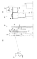
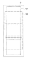
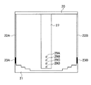
図1は、本実施の形態に係る放射線画像撮影システム(以下、「撮影システム」と称する。)における各装置の配置状態の一例を示す図である。なお、図1(A)には、撮影台45の側面図が示され、図1(B)には撮影台45の正面図が示されている。
FIG. 1 is a diagram illustrating an example of an arrangement state of each device in a radiographic image capturing system (hereinafter referred to as “imaging system”) according to the present embodiment. 1A shows a side view of the photographing stand 45, and FIG. 1B shows a front view of the photographing
撮影システムは、医師や放射線技師等(以下、撮影者)の操作により放射線画像の撮影を行う。撮影システムは、放射線源130(図6も参照。)から曝射条件に従った線量とされた放射線Xを被検者に照射する放射線発生装置34と、被検者の撮影対象部位を透過した放射線Xを吸収して電荷を発生し、発生した電荷量に基づいて放射線画像を示す画像情報を生成する放射線検出器60(図2、図6も参照。)を内蔵する可搬型の放射線撮影装置(以下、電子カセッテ)32と、電子カセッテ32を保持する撮影台45と、電子カセッテ32、放射線発生装置34、撮影台45を制御するコンソール42と、を備えている。
The imaging system captures a radiographic image by an operation of a doctor, a radiographer, or the like (hereinafter referred to as a photographer). The imaging system transmits a
撮影台45は、基台部10を備えている。基台部10には、被写体30の体軸方向(図1では、鉛直方向)に沿ってレールが設けられ、スライド連結部12をスライド(移動)可能に支持する。スライド連結部12にはスライドレール部14が連結されている。従って、基台部10のレールに沿ってスライド連結部12が鉛直方向に移動されることによりスライドレール部14がスライド連結部12と一体的に鉛直方向に移動される(第1のスライド)。
The imaging table 45 includes a
更に、スライドレール部14には鉛直方向に沿ってレールが設けられ、スライド支持部16を鉛直方向に移動可能に保持する。スライド支持部16は、電子カセッテ32を収納可能なカセッテ収納部46を支持する。従って、スライドレール部14に設けられたレールに沿ってスライド支持部16が鉛直方向に移動されることによりカセッテ収納部46がスライド支持部16と一体的に鉛直方向に移動される(第2のスライド)。
Furthermore, a rail is provided on the
本実施の形態において、第1のスライドは、撮影者が手動により行うものであり、被写体30の大きさ(身長)に応じてスライドレール部14の高さを調整するために行われる。第2のスライドは、撮影台45に設けられた不図示のモータにより行われるものであり、長尺状の放射線画像を撮影するときにカセッテ収納部46を移動して複数の撮影位置で撮影を行うために行われる。
In the present embodiment, the first slide is manually performed by the photographer, and is performed to adjust the height of the
カセッテ収納部46は、挿入部46Aを有し、挿入部46Aから電子カセッテ32を保持可能なカセッテ保持部40が(図3に示す上側保持部20を上側にした状態で)挿入される。カセッテ収納部46は挿入部46Aから挿入されたカセッテ保持部40を収納した状態で、前述したように鉛直方向にスライド可能とされる。
The
カセッテ保持部40は、電子カセッテ32を保持可能に構成されている。すなわち、本実施の形態に係る撮影システムは、電子カセッテ32が保持されたカセッテ保持部40がカセッテ収納部46に装着された状態で該カセッテ収納部46を被写体30の体軸方向(本実施の形態では鉛直方向)に移動させながら異なる複数の撮影位置で複数の放射線画像を撮影して長尺状の放射線画像を得る長尺撮影が可能に構成されている。
The
ここで、電子カセッテ32の構成について説明する。図2には、本実施の形態に係る電子カセッテ32の内部構成が示されている。
Here, the configuration of the
同図に示すように、電子カセッテ32は、放射線Xを透過させる材料からなる筐体54を備えており、防水性、密閉性を有する構造とされている。電子カセッテ32は、手術室等で使用されるとき、血液やその他の雑菌が付着するおそれがある。そこで、電子カセッテ32を防水性、密閉性を有する構造として、必要に応じて殺菌洗浄することにより、1つの電子カセッテ32を繰り返し続けて使用することができる。この筐体54の側面には接続端子32Aが設けられている。
As shown in the figure, the
筐体54の内部には、放射線Xが照射される筐体54の照射面56側から、患者による放射線Xの散乱線を除去するグリッド58、患者を透過した放射線Xを検出する放射線検出器60、及び放射線Xのバック散乱線を吸収する鉛板62が順に配設されている。なお、筐体54の照射面56をグリッド58として構成してもよい。
Inside the
また、筐体54の内部の他端側には、マイクロコンピュータを含む電子回路、及び充電可能とされた電源部96を収容するケース31が配置されている。放射線検出器60及び上記電子回路は、ケース31に配置された電源部96から供給される電力によって作動する。ケース31内部に収容された各種回路が放射線Xの照射に伴って損傷することを回避するため、ケース31の照射面56側には鉛板等を配設しておくことが望ましい。
In addition, on the other end side inside the
次に、電子カセッテ32を保持するカセッテ保持部40の構成について説明する。
Next, the configuration of the
図3には、本実施の形態に係るカセッテ保持部40の構成が示されている。
FIG. 3 shows a configuration of the
カセッテ保持部40は、上側保持部20及び下側保持部21を備えている。上側保持部20には、4つのスイッチ24A、24B、24C、24Dが設けられている。以下、各スイッチを区別しないで説明する場合には、末尾のアルファベットA〜Dを省略して説明する。各スイッチ24は、上側保持部20から突出した状態において下方から押し上げられると上側保持部20の内部に押し込まれるように構成されている。スイッチ24は、上側保持部20から突出した状態がOFF状態、上側保持部20の内部に押し込まれた状態がON状態とされる。
The
上側保持部20の両端部には、支持部22A、22Bの一端が接続されている。支持部22Aの他端は、弾性部材23Aの一端に接続され、支持部22Bの他端は、弾性部材23Bの一端に接続されている。弾性部材23A及び弾性部材23Bの各々の他端は下側保持部21の両端部に接続されている。弾性部材23A、23Bは、例えば、ばね等により構成され、鉛直方向に伸縮する。この弾性部材23A、23Bにより、上側保持部20及び下側保持部21の距離が鉛直方向に伸縮可能に構成される。
One end of each of the support portions 22 </ b> A and 22 </ b> B is connected to both end portions of the upper holding
下側保持部21の両端部は、複数の段差を備え、左右対称の階段状に形成されている。これら複数の段差は、複数種類(使用する電子カセッテ32が1種類の場合には、1種類であってもよい)の電子カセッテ32の長手方向及び短手方向の幅の各々に合致するように形成されている。なお、本実施の形態では、電子カセッテ32の種類に応じて、電子カセッテ32の撮影領域の寸法(縦横の寸法)が規定される。
Both end portions of the
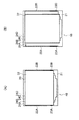
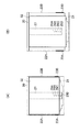
図4(A)は、カセッテ保持部40に対して、長方形の電子カセッテ32(例えば、撮影領域が半切サイズの電子カセッテ32)を横向き(電子カセッテ32の短手方向が電子カセッテ32の移動方向となる向き)に装着した状態を示す図であり、図4(B)は、カセッテ保持部40に対して、該電子カセッテ32を縦向き(電子カセッテ32の長手方向が電子カセッテ32の移動方向となる向き)に装着した状態を示す図である。
FIG. 4A shows a rectangular electronic cassette 32 (for example, an
図4(A)に示すように、電子カセッテ32をカセッテ保持部40に対して横向きに装着すると、4つのスイッチ24A、24B、24C、24Dの全てが上側保持部20の内部に押し込まれ、各々ON状態となる。また、図4(B)に示すように、該電子カセッテ32をカセッテ保持部40に対して縦向きに装着すると、4つのスイッチ24AだけがOFF状態とされ、スイッチ24B、24C、24Dの3つのスイッチが上側保持部20の内部に押し込まれ、各々ON状態となる。
As shown in FIG. 4A, when the
このように、本実施の形態では、カセッテ保持部40に設けられたスイッチ24のON・OFF状態により電子カセッテ32のカセッテ保持部40に対する装着向き(以下、単に装着向きという場合もある)を検出することが可能となっている。各スイッチ24のON・OFFの状態を示す情報(以下、スイッチ情報)は、カセッテ保持部40に設けられた接続端子40A(図6も参照)を介して、コンソール42に送信される。
As described above, in the present embodiment, the mounting direction of the
なお、コンソール42のHDD110等の記憶手段には、電子カセッテ32の種類及び装着向きと4つのスイッチ24のON・OFF状態の情報とが対応付けて記憶されている。コンソール42は、カセッテ保持部40から送信されたスイッチ情報と電子カセッテ32の種類とから、装着向きを特定することができる。
The storage means such as the
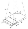
なお、本実施の形態に係るカセッテ収納部46には、着脱可能なカバー18を装着することが可能に構成されている。図1に示すように、カバー18は、カセッテ収納部46に装着された場合に、カセッテ収納部46の上端部から下方に垂れ下がった状態で、カセッテ収納部46の移動可能範囲を覆うことが可能な大きさとされている。
In addition, it is comprised in the
カバー18には、長尺の放射線画像の撮影領域(以下、長尺撮影領域)を、カセッテ保持部40に装着する電子カセッテ32の種類とカセッテ保持部40に対する電子カセッテ32の装着向きとに応じて予め定められたものとする(固定とする)場合の、該長尺撮影領域及び該長尺撮影領域を撮影するための複数の撮影位置における各撮影領域の各々が描画されている。
The
図5に示す例では、撮影領域が半切りサイズの電子カセッテ32をカセッテ保持部40に対して縦向きに装着した場合の長尺撮影領域及び該長尺撮影領域を撮影するための複数の撮影位置における撮影領域の各々が示された画像18Aと、該電子カセッテ32をカセッテ保持部40に対して横向きに装着した場合の長尺撮影領域及び該長尺撮影領域を撮影するための複数の撮影位置における撮影領域の各々が示された画像18Bと、が描画されている。なお、ここでは、隣り合う撮影位置で撮影される撮影領域の各々の一部が重なるように各撮影領域が描画されている。
In the example shown in FIG. 5, a long shooting area and a plurality of shootings for shooting the long shooting area when the
例えば、カセッテ保持部40に装着する電子カセッテ32の種類と装着向きとに応じて長尺撮影領域が一意に定められる場合には、該長尺撮影領域及び各撮影領域の各々が描画されたカバー18を装着して利用することで、撮影者は、該カバー18を参照して、どの電子カセッテ32をどの向きに装着したらよいか等を容易に決定することができる。
For example, when a long shooting area is uniquely determined according to the type and mounting direction of the
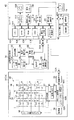
次に、図6を参照して、本実施の形態に係る撮影システムの電気系の要部構成について説明する。 Next, with reference to FIG. 6, the configuration of the main part of the electrical system of the imaging system according to the present embodiment will be described.
同図に示すように、電子カセッテ32に内蔵された放射線検出器60は、TFTアクティブマトリクス基板66上に、放射線Xを吸収し、電荷に変換する光電変換層が積層されて構成されている。光電変換層は例えばセレンを主成分(例えば含有率50%以上)とする非晶質のa−Se(アモルファスセレン)からなり、放射線Xが照射されると、照射された放射線量に応じた電荷量の電荷(電子−正孔の対)を内部で発生することで、照射された放射線Xを電荷へ変換する。なお、放射線検出器60は、アモルファスセレンのような放射線Xを直接的に電荷に変換する放射線-電荷変換材料の代わりに、蛍光体材料と光電変換素子(フォトダイオード)を用いて間接的に電荷に変換してもよい。蛍光体材料としては、ガドリニウム硫酸化物(GOS)やヨウ化セシウム(CsI)がよく知られている。この場合、蛍光体材料によって放射線X−光変換を行い、光電変換素子のフォトダイオードによって光−電荷変換を行う。
As shown in the figure, the
また、TFTアクティブマトリクス基板66上には、光電変換層で発生された電荷を蓄積する蓄積容量68と、蓄積容量68に蓄積された電荷を読み出すためのTFT70を備えた画素部74(図6では個々の画素部74に対応する光電変換層を光電変換部72として模式的に示している。)がマトリクス状に多数個配置されており、電子カセッテ32への放射線Xの照射に伴って光電変換層で発生された電荷は、個々の画素部74の蓄積容量68に蓄積される。これにより、電子カセッテ32に照射された放射線Xに担持されていた画像情報は電荷情報へ変換されて放射線検出器60に保持される。
In addition, on the TFT
また、TFTアクティブマトリクス基板66には、一定方向(行方向)に延設され、個々の画素部74のTFT70をオン・オフさせるための複数本のゲート配線76と、ゲート配線76と直交する方向(列方向)に延設され、オンされたTFT70を介して蓄積容量68から蓄積電荷を読み出すための複数本のデータ配線78が設けられている。個々のゲート配線76はゲート線ドライバ80に接続されており、個々のデータ配線78は信号処理部82に接続されている。個々の画素部74の蓄積容量68に電荷が蓄積されると、個々の画素部74のTFT70は、ゲート線ドライバ80からゲート配線76を介して供給される信号により行単位で順にオンされ、TFT70がオンされた画素部74の蓄積容量68に蓄積されている電荷は、アナログの電気信号としてデータ配線78を伝送されて信号処理部82に入力される。従って、個々の画素部74の蓄積容量68に蓄積されている電荷は行単位で順に読み出される。
The TFT
一方、信号処理部82は、個々のデータ配線78毎に設けられた増幅器及びサンプルホールド回路を備えており、個々のデータ配線78を伝送された電荷信号は増幅器で増幅された後にサンプルホールド回路に保持される。また、サンプルホールド回路の出力側にはマルチプレクサ、A/D(アナログ/デジタル)変換器が順に接続されており、個々のサンプルホールド回路に保持された電荷信号はマルチプレクサに順に(シリアルに)入力され、A/D変換器によってデジタルの画像データへ変換される。
On the other hand, the
信号処理部82には画像メモリ90が接続されており、信号処理部82のA/D変換器から出力された画像データは画像メモリ90に順に記憶される。画像メモリ90は複数フレーム分の画像データを記憶可能な記憶容量を有しており、放射線画像の撮影が行われる毎に、撮影によって得られた画像データが画像メモリ90に順次記憶される。
An
画像メモリ90は電子カセッテ32全体の動作を制御するカセッテ制御部92と接続されている。カセッテ制御部92はマイクロコンピュータを含んで構成されており、CPU(中央処理装置)92A、ROM(Read Only Memory)及びRAM(Random Access Memory)を含むメモリ92B、HDD(ハードディスク・ドライブ)やフラッシュメモリ等からなる不揮発性の記憶部92Cを備えている。記憶部92Cには、自身の種類を示す種類情報が予め記憶されている。また、記憶部92Cには、コンソール42から種類情報の要求を受けた場合に、記憶されている種類情報を通信部95を介してコンソール42に送信するためのプログラムも記憶されている。
The
また、カセッテ制御部92には通信部95が接続されている。通信部95は、接続端子32Aに接続され、接続端子32Aを介してコンソール42との間で各種情報の伝送を制御する。
A
また、電子カセッテ32には電源部96が設けられており、上述した各種回路や各素子(ゲート線ドライバ80、信号処理部82、画像メモリ90、無線通信部94、カセッテ制御部92等)は、電源部96から供給された電力によって作動する。電源部96は、電子カセッテ32の可搬性を損なわないように、前述したバッテリ(二次電池)96Aを内蔵しており、充電されたバッテリ96Aから各種回路や各素子へ電力を供給する。なお、図6では、電源部96と各種回路や各素子を接続する配線の図示を省略している。
The
一方、コンソール42は、サーバ・コンピュータとして構成されており、操作メニューや撮影された放射線画像等を表示するディスプレイ100と、複数のキーを含んで構成され、各種の情報や操作指示が入力される操作パネル102と、を備えている。
On the other hand, the
また、本実施の形態に係るコンソール42は、装置全体の動作を司るCPU104と、制御プログラムを含む各種プログラム等が予め記憶されたROM106と、各種データを一時的に記憶するRAM108と、各種データを記憶して保持するHDD110と、ディスプレイ100への各種情報の表示を制御するディスプレイドライバ112と、操作パネル102に対する操作状態を検出する操作入力検出部114と、を備えている。また、コンソール42は、接続端子42Aに接続され、接続端子42A及び通信ケーブルを介して放射線発生装置34との間で曝射条件等の各種情報の送受信を行う通信インタフェース(I/F)部116と、電子カセッテ32との間で曝射条件や画像データ等の各種情報の送受信を行うカセッテ通信部118と、電子カセッテ32を保持するカセッテ保持部40との間でスイッチ情報の各種情報を受信する保持部通信部122と、を備えている。また、コンソール42は、前述したスライド支持部16をスライドレール部14のレールに沿って移動させるためのモータを駆動するモータドライバ44を制御するモータ制御部120を備えている。
The
CPU104、ROM106、RAM108、HDD110、ディスプレイドライバ112、操作入力検出部114、通信I/F部116、カセッテ通信部118、モータ制御部120、及び保持部通信部122は、システムバスBUSを介して相互に接続されている。従って、CPU104は、ROM106、RAM108、HDD110へのアクセスを行うことができると共に、ディスプレイドライバ112を介したディスプレイ100への各種情報の表示の制御、通信I/F部116を介した放射線発生装置34との各種情報の送受信の制御、及びカセッテ通信部118を介した電子カセッテ32との各種情報の送受信の制御、保持部通信部122を介したカセッテ保持部40との各種情報の送受信の制御、及びモータ制御部120を介したモータドライバ44の制御を各々行うことができる。また、CPU104は、操作入力検出部114を介して操作パネル102に対するユーザの操作状態を把握することができる。
The
放射線発生装置34には、コンソール42と通信を行うための接続端子34Aが設けられている。コンソール42には、放射線発生装置34と通信を行うための接続端子42Aが設けられている。放射線発生装置34の接続端子34Aとコンソール42の接続端子42Aは通信ケーブルによって接続されている。また、放射線発生装置34は、放射線Xを射出する放射線源130と、コンソール42との間で曝射条件等の各種情報を送受信する通信I/F部132と、通信I/F部132を介して受信した曝射条件に基づいて放射線源130を制御する線源制御部134と、を備えている。
The
線源制御部134はマイクロコンピュータによって構成されており、受信した曝射条件や姿勢情報を記憶する。コンソール42から受信する曝射条件には管電圧、管電流、照射期間等の情報が含まれている。線源制御部134は、受信した曝射条件に基づいて放射線源130から放射線Xを照射させる。
The radiation
放射線源130は、X線管球及びコリメータを含んで構成され、該コリメータ近辺には、長尺撮影領域の鉛直方向の範囲(以下、長尺撮影範囲という)特定用のレーザを照射するレーザ光源136が設けられている。レーザ光源136は、赤色或いは緑色等のレーザ光を照射する。レーザ光源136によるレーザ光の照射は、レーザ制御部138により制御される。
The
更にまた、放射線発生装置34は、操作部140及び首振り機構部142を備えている。首振り機構部142は、首振り軸を備え、首振り軸を回転軸として鉛直方向に放射線源130、レーザ光源136の首振りを行う。首振り機構部142により、放射線源130の放射線X及びレーザ光源136のレーザ光の照射位置の変更を可能にする。撮影者は、操作部140を操作することにより、首振り機構部142の首振り動作を操作したり、レーザ制御部138に対するレーザ光源136の点灯・消灯させるための指示を入力したりする。また、操作部140は、ボタン140A(図1も参照。)を備えている。首振り機構部142による首振り動作中に、レーザ光源136を点灯させた状態でボタン140Aを押下することにより、撮影者は長尺撮影範囲を指定することができる。なお、首振り機構部142は、操作部140による操作の他、通信I/F部132を介してコンソール42から受信した指示情報に基づいて動作する。
Furthermore, the
カセッテ保持部40は、接続端子40A、検出部25及び通信部26を備えている。通信部26は、接続端子40Aを介してコンソール42の保持部通信部122に接続される。検出部25は、前述したスイッチ24A、24B、24C、24Dの4つのスイッチと、各スイッチ24のON・OFFの状態をデジタル信号に変換してスイッチ情報を生成する信号処理部とを備えている。信号処理部で変換されたスイッチ情報は、通信部26を介してコンソール42に送信される。
The
次に、本実施の形態に係る撮影システムの作用を説明する。 Next, the operation of the imaging system according to the present embodiment will be described.
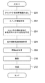
まず、撮影者が電子カセッテ32とコンソール42とを接続すると、コンソール42は、図7に示す処理ルーチンの実行を開始する。この処理ルーチンのプログラムは、ROM106に記憶され、CPU104により実行される。
First, when the photographer connects the
ステップ200では、電子カセッテ32に記憶された種類情報を読み出す。具体的には、電子カセッテ32に対して、種類情報の要求を送信する。電子カセッテ32のカセッテ制御部92は、この種類情報の要求を受信すると、記憶部92Cに予め記憶されている種類情報を読み出して、通信部95を介してコンソール42に送信する。これにより、コンソール42は、電子カセッテ32から電子カセッテ32の種類を示す種類情報を取得する。
In
ステップ202では、電子カセッテ32がカセッテ保持部40にセットされた後、カセッテ保持部40に対してスイッチ情報を要求し、カセッテ保持部40からスイッチ情報を取得する。
In
ステップ204では、電子カセッテ32から取得した種類情報と、カセッテ保持部40から取得したスイッチ情報とに基づいて、電子カセッテ32の装着向きを特定し、更に電子カセッテ32の種類情報と電子カセッテ32の装着向きとに基づいて、電子カセッテ32の撮影領域の鉛直方向の長さを特定する。以下、電子カセッテ32の撮影領域の鉛直方向の長さを特定する方法の一例について具体的に説明する。
In
前述したように、電子カセッテ32の種類により、電子カセッテ32の撮影領域の縦横の寸法が規定される。従って、電子カセッテ32の撮影領域が長方形の場合、撮影領域の長手方向及び短手方向の長さは、電子カセッテ32の種類により判断可能となる。種類情報と撮影領域の長手方向及び短手方向の長さとを対応付けたテーブルは、予めコンソール42のHDD110に記憶されており、電子カセッテ32から取得した種類情報に対応付けて記憶されている撮影領域の長手方向及び短手方向の長さを読み出すことにより、カセッテ保持部40に装着(保持)された電子カセッテ32の撮影領域の寸法を取得する。
As described above, the vertical and horizontal dimensions of the imaging area of the
次に、カセッテ保持部40から受信したスイッチ情報が示す各スイッチ24のON/OFF状態から、カセッテ保持部40に対する電子カセッテ32の装着向きを判断する。図4(A)に示す例では、スイッチ24が全てON状態であるため、横向きであると判断され、図4(B)に示す例では、スイッチ24AのみがOFF状態で、それ以外のスイッチ24B、24C、24DがON状態であるため、縦向きであると判断される。
Next, the mounting orientation of the
電子カセッテ32の装着向きが縦向きを示していた場合には、電子カセッテ32の撮影領域の長手方向の長さを、電子カセッテ32の撮影領域の鉛直方向の長さとして特定する。また、カセッテ保持部40から受信した電子カセッテ32の装着向きの検出結果が、横向きを示していた場合には、電子カセッテ32の撮影領域の短手方向の長さを、電子カセッテ32の撮影領域の鉛直方向の長さとして特定する。なお、電子カセッテ32の撮影領域が正方形である場合には、上記テーブルには、撮影領域の一辺の長さが記憶され、装着向きを判断することなく、上記撮影領域の一辺の長さをそのまま、電子カセッテ32の撮影領域の鉛直方向の長さとして用いる。
When the mounting direction of the
次に、ステップ206において、長尺撮影範囲の上端位置及び下端位置を示す情報(長尺撮影範囲情報)を取得する。以下、具体的に説明する。
Next, in
撮影者は、カセッテ保持部40に電子カセッテ32をセットした後、該カセッテ保持部40を、上側保持部20を上側にした状態でカセッテ収納部46に収納する。更に、撮影者は、放射線発生装置34の操作部140を操作してレーザ光源136のレーザ光の照射を開始する。また、撮影者は、被写体30である患者を撮影台45の前に立たせ、手動でスライド連結部12をスライドさせて、スライドレール部14に設けられたレールの鉛直方向の中心位置の高さ(Z方向とする)を、被写体30の身長に合わせて撮影したい長尺撮影範囲の中心(Z=0とする)まで移動させる。このときのスライド量(移動量)を示す情報は、コンソール42から放射線発生装置34に送信される。首振り機構部142は、この情報に応じて首振り動作を行い、レーザ光の照射位置が、Z=0(スライドレール部14のレールの中心高さ)に合わせられる。
The photographer sets the
続いて、撮影者は、操作部140を操作して首振り機構部142に首振り動作を行わせる。これにより、レーザ光の照射位置が上下する。撮影者は、レーザ光を目視により確認しながら、長尺撮影範囲の上端と下端を指定する。具体的には、レーザ光の照射位置が、所望の長尺撮影範囲の上端の位置及び下端の位置の各々に移動されたときに、操作部140のボタン140Aを押下して指定する。ボタン140Aを押下したときのレーザ光の照射位置を示す情報が長尺撮影範囲情報として、通信I/F部132を介してコンソール42に送信される。
Subsequently, the photographer operates the operation unit 140 to cause the
コンソール42は、放射線発生装置34から長尺撮影範囲情報を受信することにより、長尺撮影範囲情報を取得する。
The
ステップ208では、長尺撮影領域を撮影するための複数の撮影位置の間隔dを決定する。具体的には、オーバーラップ量(隣り合う撮影領域の一部が重なるように撮影する場合の重なり領域の鉛直方向の長さ)が予め定められている場合には、上記特定した電子カセッテ32の撮影領域の鉛直方向の長さからオーバーラップ量を減算した長さを間隔dとして決定する。オーバーラップ量が0でなければ、間隔dは、上記特定した電子カセッテ32の撮影領域の鉛直方向の長さより短くなる。また、オーバーラップ量を0とする場合には、上記特定した電子カセッテ32の撮影領域の鉛直方向の長さをそのまま複数の撮影位置の間隔dとして決定する。なお、撮影位置の数を可変とする場合には、オーバーラップ量をaとし、上記特定した電子カセッテ32の撮影領域の鉛直方向の長さをbとし、上記指定された長尺撮影範囲の長さをcとし、撮影位置の数をxとしたときに、数式「{bx−a(x−1)}≧c」を満たすようにxを求めることができる。
In
また、オーバーラップ量の範囲(上限値及び下限値)が予め定められている場合であって、例えば撮影位置の数が3箇所(撮影枚数が3枚と言い換えても良い)として予め定められている場合には、オーバーラップ量が予め定められた範囲内で、且つ鉛直方向の長さが上記指定された長尺撮影範囲の長さ以上の範囲が撮影されるように、3箇所の撮影位置の間隔dを決定する。 In addition, the overlap amount range (upper limit value and lower limit value) is determined in advance, and for example, the number of shooting positions is determined in advance as three places (the number of shots may be referred to as three). If there is an overlap amount, the three shooting positions are set so that the range in which the overlap amount is within a predetermined range and the length in the vertical direction is longer than the length of the designated long shooting range is shot. The interval d is determined.
例えば、オーバーラップ量をaとし、上記特定した電子カセッテ32の撮影領域の鉛直方向の長さをbとし、上記指定された長尺撮影範囲の長さをcとしたときに、以下の数式「(3b−2a)≧c」を満たすようにする。ここで、オーバーラップ量の範囲が定められており、aはこの範囲内で可変であるため、この範囲内で且つ上記数式を満たすaを求め、bから上記決定したaの値を減算した値を間隔dとして決定する。
For example, when the overlap amount is a, the vertical length of the imaging region of the specified
なお、間隔dの決定方法は、ここで説明した例に限定されず、様々な方法を採用することができる。 Note that the method of determining the interval d is not limited to the example described here, and various methods can be employed.
ステップ210では、決定された間隔dだけ隔てた複数の撮影位置で放射線画像が撮影されるようにカセッテ収納部46(スライド支持部16)を該複数の撮影位置に移動して、該複数の撮影位置の各々で放射線画像が撮影されるように制御する。
In
以下、カセッテ収納部46(スライド支持部16)の移動の一例を説明する。ここでは、図8を参照しながら、3箇所の撮影位置で撮影する場合を例に挙げて説明する。 Hereinafter, an example of the movement of the cassette storage unit 46 (slide support unit 16) will be described. Here, a case where shooting is performed at three shooting positions will be described as an example with reference to FIG.
まず、モータ制御部120によりモータドライバ44を制御して、電子カセッテ32の撮影領域の鉛直方向の中心位置が、z=dの高さになるようにカセッテ収納部46(スライド支持部16)を移動させる。
First, the
この状態で、1枚目の放射線画像を撮影する。具体的には、電子カセッテ32の放射線検出器60で電荷蓄積が開始されるようにコンソール42から電子カセッテ32に対して指示情報を送信すると共に、この撮影位置の撮影領域に向けて放射線源130から放射線Xが照射されるように、コンソール42から放射線発生装置34に対して曝射開始を指示する指示情報(曝射条件や撮影位置を示す情報を含む)を送信する。これに応じて、放射線発生装置34の首振り機構部142は、放射線Xの照射位置を首振り動作により変更し、線源制御部134は、予め指示された曝射条件に応じた放射線Xが照射されるように放射線源130を制御する。なお、不要な部分へのX線照射を避けるため,適宜コリメータでX線照射範囲を調整する。
In this state, the first radiation image is taken. Specifically, instruction information is transmitted from the
放射線検出器60で一定期間蓄積された電荷は、各データ配線78を介して信号処理部82に入力され、信号処理部82でデジタルの画像データに変換されて、画像メモリ90に記憶される。そして、電子カセッテ32のカセッテ制御部92は、画像メモリ90から画像データを読み出してコンソール42に送信する。これにより、コンソール42は、1枚目の放射線画像の画像データを受信することができる。
The charges accumulated for a certain period of time by the
次に、モータ制御部120によりモータドライバ44を制御して、電子カセッテ32の撮影領域の鉛直方向の中心位置が、z=0の高さになるようにカセッテ収納部46(スライド支持部16)を移動させる。
Next, the
この状態で、2枚目の放射線画像を撮影する。撮影方法は、1枚目と同様である。 In this state, a second radiation image is taken. The shooting method is the same as that for the first image.
同様に、電子カセッテ32の撮影領域の鉛直方向の中心位置が、z=−dの高さになるようにカセッテ収納部46(スライド支持部16)を移動させる。
Similarly, the cassette storage section 46 (slide support section 16) is moved so that the vertical center position of the imaging area of the
この状態で、3枚目の放射線画像を撮影する。撮影方法は、1枚目と同様である。 In this state, a third radiographic image is taken. The shooting method is the same as that for the first image.
なお、複数の放射線画像の撮影方法はこれに限定されない。例えば、カセッテ収納部46を下方の撮影位置から上方の撮影位置へ順に移動させて撮影するようにしてもよい。また、最初にカセッテ収納部46を複数の撮影位置の真ん中の撮影位置に移動させて撮影し、その後、その位置から上方の撮影位置に移動して撮影した後、下方の撮影位置に移動して撮影するようにしてもよい。何れの場合であっても、上記複数の撮影位置の間隔が、上記決定した間隔dとなるようにカセッテ収納部46を移動する。
In addition, the imaging | photography method of a some radiographic image is not limited to this. For example, the
ステップ212では、撮影により得られた複数の放射線画像の画像データを連結して合成し、長尺の放射線画像を示す画像データを生成する。なお、オーバーラップ領域については、何れか一方の放射線画像の画像データを用いるようにしてもよいし、2つの放射線画像を合成した画像データを用いるようにしてもよい。生成された長尺の放射線画像を示す画像データは、ディスプレイ100に表示される。
In
なお、電子カセッテ32を交換する場合には、上記処理ルーチンを最初から繰り返す。また、電子カセッテ32のカセッテ保持部40に対する装着向きのみを変更する場合には、上記処理ルーチンのステップ202から繰り返す。また、電子カセッテ32の装着向きはそのままで、長尺撮影範囲を変更して撮影する場合には、ステップ206から繰り返す。
When the
以上詳細に説明したように、本実施の形態によれば、電子カセッテ32を保持したカセッテ保持部40がカセッテ収納部46に装着された状態で該カセッテ収納部46を所定方向(ここでは、被写体30の体軸方向、鉛直方向)に移動させながら異なる複数の撮影位置で複数の放射線画像を撮影して長尺状の放射線画像を得る長尺撮影を行う際、装着された電子カセッテ32の撮影領域の鉛直方向の長さを特定し、該特定された長さに基づいて、複数の撮影位置の間隔を決定し、該決定された間隔を隔てた複数の撮影位置の各々で放射線画像が撮影されるようにカセッテ収納部46を移動するようにしたため、使用する電子カセッテ32の種類や装着向きを変更しても、手間をかけずに適切な移動間隔を決定して長尺状の放射線画像を撮影することができる。従って、1台の装置で、電子カセッテ32を縦向きにしても横向きにしても簡易に長尺撮影ができるので、撮影者は所望の長尺撮影領域に合わせて、電子カセッテ32の種類や装着向きを選択できる。
As described above in detail, according to the present embodiment, the
以上、本発明を実施の形態を用いて説明したが、本発明の技術的範囲は上記実施の形態に記載の範囲には限定されない。発明の要旨を逸脱しない範囲で上記実施の形態に多様な変更又は改良を加えることができ、当該変更又は改良を加えた形態も本発明の技術的範囲に含まれる。 As mentioned above, although this invention was demonstrated using embodiment, the technical scope of this invention is not limited to the range as described in the said embodiment. Various changes or improvements can be added to the above-described embodiment without departing from the gist of the invention, and embodiments to which the changes or improvements are added are also included in the technical scope of the present invention.
また、上記の実施の形態は、クレーム(請求項)にかかる発明を限定するものではなく、また実施の形態の中で説明されている特徴の組み合わせの全てが発明の解決手段に必須であるとは限らない。前述した実施の形態には種々の段階の発明が含まれており、開示される複数の構成要件における適宜の組み合わせにより種々の発明を抽出できる。実施の形態に示される全構成要件から幾つかの構成要件が削除されても、効果が得られる限りにおいて、この幾つかの構成要件が削除された構成が発明として抽出され得る。 The above embodiments do not limit the invention according to the claims (claims), and all the combinations of features described in the embodiments are essential for the solution means of the invention. Is not limited. The embodiments described above include inventions at various stages, and various inventions can be extracted by appropriately combining a plurality of disclosed constituent elements. Even if some constituent requirements are deleted from all the constituent requirements shown in the embodiment, as long as an effect is obtained, a configuration from which these some constituent requirements are deleted can be extracted as an invention.
例えば、上記実施の形態では、カセッテ保持部40に設けられた複数個のスイッチ24で電子カセッテ32の装着向きを検出する例について説明したが、これに限定されず、例えば、カセッテ保持部40に光学式のセンサを複数個配置し、該複数個のセンサの遮蔽状態から電子カセッテ32の装着向きを検出するようにしてもよい。
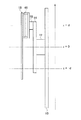
For example, in the above embodiment, the example in which the mounting orientation of the
例えば、カセッテ保持部40を図9に示すように構成することができる。カセッテ保持部40の上側保持部20には、4つのスイッチ24の代わりに、複数個の光学式のセンサ(図では、光学式センサ29A、29B、29C、29Dの4つのセンサ)が配置されたセンサ支持部27が接続されている。
For example, the
図10(A)は、図9に示すカセッテ保持部40に対して、長方形の電子カセッテ32(例えば、撮影領域が半切サイズの電子カセッテ32)を横向きに装着した状態を示す図であり、図10(B)は、図9に示すカセッテ保持部40に対して、該電子カセッテ32を縦向きに装着した状態を示す図である。
FIG. 10A is a diagram showing a state in which a rectangular electronic cassette 32 (for example, an
図10(A)に示すように、電子カセッテ32をカセッテ保持部40に対して横向きに装着すると、光学式センサ29A、29B、29Cの3つが遮蔽された状態となり、光学式センサ29Dが露出した状態となる。また、図10(B)に示すように、該電子カセッテ32をカセッテ保持部40に対して縦向きに装着すると、光学式センサ29A、29B、29C,29Dの4つのセンサ全てが遮蔽された状態となる。
As shown in FIG. 10A, when the
このように、図9に示すカセッテ保持部40は、複数の光学式センサ29の遮蔽状態により電子カセッテ32のカセッテ保持部40に対する装着向きを検出することが可能に構成されている。各光学式センサ29の遮蔽状態を示す情報は、カセッテ保持部40に設けられた接続端子40A(図6も参照)を介して、コンソール42に送信される。
As described above, the
コンソール42のHDD110には、電子カセッテ32の種類及び装着向きと4つの光学式センサ29の遮蔽状態の情報とが対応付けて記憶されている。コンソール42は、カセッテ保持部40から送信された各光学式センサ29の遮蔽状態を示す情報と電子カセッテ32の種類とから、装着向きを判断することができる。
In the
また、上記では、電子カセッテ32の装着向きをカセッテ保持部40にスイッチ24や光学式センサ29により検出する例について説明したが、これに限定されず、例えば、装着向きを検出する検出手段を電子カセッテ32側に設けても良い。例えば、電子カセッテ32に、加速度を検出する加速度センサ、重力を検出する重力センサ、電子カセッテ32の縁がカセッテ保持部40の下側保持部21の何れかの段差に接触したときの圧力を検出する圧力センサ等、何れかを設け、設けたセンサの検出結果をコンソール42が取得するようにしてもよい。コンソール42は、これらセンサの検出結果から装着向きを特定できる。
In the above description, the example in which the mounting orientation of the
また、上記では、電子カセッテ32に記憶された種類情報を読み出すことにより、電子カセッテ32の種類を取得する例について説明したが、これに限定されず、コンソール42のディスプレイに電子カセッテ32の種類を示す情報を設定する設定画面を表示するようにし、撮影者が操作パネル102を操作して該設定画面に電子カセッテ32の種類を示す情報を入力して設定するようにしてもよい。ここで設定された種類情報を、カセッテ保持部40に装着する電子カセッテ32の種類として取得して用いることができる。
In the above description, the example in which the type of the
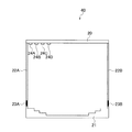
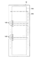
また、上記実施の形態では、電子カセッテ32の種類と装着向きとに応じて、電子カセッテ32の撮影領域の(被写体30の体軸方向の)長さを特定する例について説明したが、これに限定されるものではない。例えば、図5に示すカバー18に代えて、図11に示すように複数の指標(マーカ)18Cを並べて描画したカバー18を用意する。このカバー18をカセッテ収納部46の上端部から下方に垂れ下げた状態で、カセッテ収納部46の移動可能な範囲を覆い、この状態で、放射線画像を仮撮影する。このとき撮影された放射線画像に含まれる指標18Cを示す画像に基づいて、電子カセッテ32の撮影領域の(被写体30の体軸方向の)長さを特定するようにしてもよい。例えば、放射線画像に写りこんだ指標18Cの数などにより特定することができる。
In the above-described embodiment, the example in which the length of the imaging region of the electronic cassette 32 (in the body axis direction of the subject 30) is specified according to the type and mounting direction of the
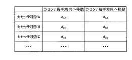
また、上記実施の形態では、長尺撮影範囲を撮影者が指定可能に構成し、該長尺撮影範囲に合わせて複数の撮影位置の間隔dを求める例について説明したが、これに限定されず、例えば、電子カセッテ32の種類及び装着向きに応じて一意に長尺撮影領域が定まるように運用する場合には(すなわち、長尺撮影領域を電子カセッテ32の種類及び装着向きに応じて固定とする)、該長尺撮影領域に合わせて前述のように間隔dを求めるようにしてもよい。また、電子カセッテ32の種類及び装着向きに応じて予め間隔dの固定値を設定しておき、該設定値を読み出して長尺撮影の際の複数の撮影位置の間隔dとして決定してもよい。例えば、図12に示すように、電子カセッテ32の種類(種類A,種類B,種類C・・・)と装着向き(カセッテ長手方向へ移動、カセッテ短手方向へ移動)とに応じて間隔dの値を登録したテーブルを予めコンソール42のHDD110等に記憶しておき、電子カセッテ32の種類と装着向き判明後、該テーブルから該当する間隔dを読み出し、読み出した間隔dを長尺撮影の際の複数の撮影位置の間隔dとして決定する。これによっても、上記と同様の効果が得られる。
In the above-described embodiment, an example has been described in which a photographer can designate a long shooting range and the interval d between a plurality of shooting positions is obtained in accordance with the long shooting range. However, the present invention is not limited to this. For example, when operating so that the long imaging region is uniquely determined according to the type and mounting orientation of the electronic cassette 32 (that is, the long imaging region is fixed according to the type and mounting orientation of the electronic cassette 32). The interval d may be obtained as described above in accordance with the long imaging region. In addition, a fixed value of the interval d may be set in advance according to the type and mounting orientation of the
また、上記実施の形態では、放射線発生装置34に首振り機構部142を設け、首振り動作を行うことにより、放射線源130の放射線X及びレーザ光源136のレーザ光の照射位置を変更するように構成した例について説明したが、これに限定されず、例えば、首振り機構部142の代わりに、放射線源130、レーザ光源136を鉛直方向(図1の鉛直方向)に移動可能に支持する支持移動機構を設け、支持移動機構により、放射線源130、レーザ光源136を鉛直方向に移動させることで、放射線源130の放射線X及びレーザ光源136のレーザ光の照射位置を変更するように構成してもよい。
In the above embodiment, the
また、上記実施形態では、放射線としてX線を用いて説明したが、特にこれに限定されるものではなく、γ線等であってもよい。 Moreover, although the said embodiment demonstrated using X-rays as a radiation, it is not specifically limited to this, A gamma ray etc. may be sufficient.
また、上記実施形態では、立位状態での長尺撮影に電子カセッテ32及び撮影台45を用いたが、臥位状態での長尺撮影に電子カセッテ32及び撮影台45を用いてもよい。この場合には、電子カセッテ32が水平方向に移動するように撮影台45を構成することで、長尺撮影が可能となる。
Moreover, in the said embodiment, although the
また、上記実施の形態では、放射線を直接デジタルデータに変換できる放射線検出器を有する電子カセッテ32を移動して複数の撮影位置で複数の放射線画像を撮影することにより長尺の放射線画像を撮影する例について説明したが、電子カセッテ32に限定されるものではなく、例えば放射線エネルギーを蓄積する輝尽性蛍光体シート(イメージングプレートともいう)やフイルムを格納したカセッテ(CRカセッテ)を移動して複数の撮影位置で複数の放射線画像を撮影することにより長尺の放射線画像を撮影するものであってもよい。
In the above embodiment, a long radiation image is captured by moving the
また、上記実施の形態では、電子カセッテ32とコンソール42との間、放射線発生装置34とコンソール42との間、カセッテ保持部40とコンソール42との間で、無線にて通信を行う場合について説明したが、本発明はこれに限定されるものではなく、例えば、これらの少なくとも1つを有線にて通信を行う形態としてもよい。
Moreover, in the said embodiment, the case where it communicates by radio | wireless between the
その他、上記実施の形態で説明した電子カセッテ32の構成(図2参照。)、撮影システムの構成(図1参照。)は一例であり、本発明の主旨を逸脱しない範囲内において、不要な部分を削除したり、新たな部分を追加したり、接続状態等を変更したりすることができることは言うまでもない。 In addition, the configuration of the electronic cassette 32 (see FIG. 2) and the configuration of the imaging system (see FIG. 1) described in the above embodiment are merely examples, and unnecessary portions are within the scope not departing from the gist of the present invention. Needless to say, can be deleted, a new part can be added, or the connection state can be changed.
また、上記実施の形態で説明した各種プログラムの処理の流れ(図7参照。)も一例であり、本発明の主旨を逸脱しない範囲内において、不要なステップを削除したり、新たなステップを追加したり、処理順序を入れ換えたりすることができることは言うまでもない。 Further, the processing flow of various programs described in the above embodiment (see FIG. 7) is also an example, and unnecessary steps are deleted or new steps are added within the scope of the present invention. Needless to say, the processing order can be changed.
10 基台部
12 スライド連結部
14 スライドレール部
16 スライド支持部
18 カバー
24A〜24D スイッチ
25 検出部
26 通信部
27 センサ支持部
29A〜29D 光学式センサ
32 電子カセッテ
34 放射線発生装置
40 カセッテ保持部
42 コンソール
45 撮影台
46 カセッテ収納部
DESCRIPTION OF
Claims (9)
前記特定手段により特定された長さに基づいて、前記複数の撮影位置の間隔を決定する決定手段と、
前記決定手段で決定された間隔を隔てた複数の撮影位置の各々で放射線画像が撮影されるように前記装着部を移動する移動手段と、
前記装着部の移動可能な範囲を覆うことが可能で、複数の指標が前記所定方向に並べて描画された指標描画カバーと、
を備え、
前記特定手段は、前記放射線撮影装置が装着された装着部の移動可能な範囲を前記指標描画カバーで覆った状態で仮撮影を行ったときに得られた放射線画像に含まれる指標を示す画像に基づいて、前記長さを特定する
放射線画像撮影システム。 A plurality of different radiation imaging apparatuses that detect radiation emitted from a radiation source and pass through the subject and acquire a radiation image of the subject are mounted on the mounting unit while the mounting unit is moved in a predetermined direction. When taking a plurality of radiation images at an imaging position to obtain a long radiation image, the length in the predetermined direction of the imaging region of the radiation imaging apparatus attached to the attachment unit is specified. Specific means,
Determining means for determining intervals between the plurality of shooting positions based on the length specified by the specifying means;
Moving means for moving the mounting portion so that a radiographic image is captured at each of a plurality of imaging positions separated by an interval determined by the determining means;
An index drawing cover that can cover a movable range of the mounting portion, and in which a plurality of indexes are drawn side by side in the predetermined direction;
Equipped with a,
The specifying means is an image showing an index included in a radiographic image obtained when provisional imaging is performed in a state in which a movable range of the mounting unit on which the radiation imaging apparatus is mounted is covered with the index drawing cover. Identify the length based on
Radiation imaging system.
前記特定手段により特定された長さに基づいて、前記複数の撮影位置の間隔を決定する決定手段と、
前記決定手段で決定された間隔を隔てた複数の撮影位置の各々で放射線画像が撮影されるように前記装着部を移動する移動手段と、
を備え、
前記装着部は、前記装着された放射線撮影装置の前記装着部に対する向きを検出する検出手段を有し、
前記特定手段は、前記装着部に装着する放射線撮影装置の種類を取得する種類取得手段を備え、前記種類取得手段で取得された種類に応じて定まる前記放射線撮影装置の撮影領域の長手方向の寸法及び短手方向の寸法と、前記検出手段により検出された向きとに基づいて、前記放射線撮影装置の撮影領域の前記所定方向の長さを特定し、
前記装着部の移動可能範囲を覆うことが可能で、前記放射線撮影装置の種類及び前記装着部に対する向きに応じて定まる長尺の撮影領域、及び該長尺の撮影領域を撮影するための前記複数の撮影位置における各撮影領域の各々が描画された撮影領域描画カバー
を更に備えた
放射線画像撮影システム。 A plurality of different radiation imaging apparatuses that detect radiation emitted from a radiation source and pass through the subject and acquire a radiation image of the subject are mounted on the mounting unit while the mounting unit is moved in a predetermined direction. When taking a plurality of radiation images at an imaging position to obtain a long radiation image, the length in the predetermined direction of the imaging region of the radiation imaging apparatus attached to the attachment unit is specified. Specific means,
Determining means for determining intervals between the plurality of shooting positions based on the length specified by the specifying means;
Moving means for moving the mounting portion so that a radiographic image is captured at each of a plurality of imaging positions separated by an interval determined by the determining means;
Equipped with a,
The mounting unit includes a detecting unit that detects an orientation of the mounted radiographic apparatus with respect to the mounting unit;
The specifying unit includes a type acquiring unit that acquires a type of a radiographic apparatus to be mounted on the mounting unit, and is a dimension in a longitudinal direction of an imaging region of the radiographic apparatus that is determined according to the type acquired by the type acquiring unit. And the length in the predetermined direction of the imaging region of the radiation imaging apparatus based on the dimension in the lateral direction and the direction detected by the detection means,
A long imaging region that can cover the movable range of the mounting unit and is determined according to the type of the radiation imaging apparatus and the orientation with respect to the mounting unit, and the plurality of imaging units for imaging the long imaging region An imaging area drawing cover in which each of the imaging areas at each imaging position is drawn
Further provided
Radiation imaging system.
前記特定手段により特定された長さに基づいて、前記複数の撮影位置の間隔を決定する決定手段と、
前記決定手段で決定された間隔を隔てた複数の撮影位置の各々で放射線画像が撮影されるように前記装着部を移動する移動手段と、
を備え、
前記放射線撮影装置に、自身の前記装着部に対する向きを検出する検出手段を設け、
前記特定手段は、前記装着部に装着する放射線撮影装置の種類を取得する種類取得手段を備え、前記種類取得手段で取得された種類に応じて定まる前記放射線撮影装置の撮影領域の長手方向の寸法及び短手方向の寸法と、前記検出手段により検出された向きとに基づいて、前記放射線撮影装置の撮影領域の前記所定方向の長さを特定し、
前記装着部の移動可能範囲を覆うことが可能で、前記放射線撮影装置の種類及び前記装着部に対する向きに応じて定まる長尺の撮影領域、及び該長尺の撮影領域を撮影するための前記複数の撮影位置における各撮影領域の各々が描画された撮影領域描画カバー
を更に備えた
放射線画像撮影システム。 A plurality of different radiation imaging apparatuses that detect radiation emitted from a radiation source and pass through the subject and acquire a radiation image of the subject are mounted on the mounting unit while the mounting unit is moved in a predetermined direction. When taking a plurality of radiation images at an imaging position to obtain a long radiation image, the length in the predetermined direction of the imaging region of the radiation imaging apparatus attached to the attachment unit is specified. Specific means,
Determining means for determining intervals between the plurality of shooting positions based on the length specified by the specifying means;
Moving means for moving the mounting portion so that a radiographic image is captured at each of a plurality of imaging positions separated by an interval determined by the determining means;
Equipped with a,
The radiation imaging apparatus is provided with detection means for detecting the orientation of the radiation imaging apparatus with respect to the mounting unit
The specifying unit includes a type acquiring unit that acquires a type of a radiographic apparatus to be mounted on the mounting unit, and is a dimension in a longitudinal direction of an imaging region of the radiographic apparatus that is determined according to the type acquired by the type acquiring unit. And the length in the predetermined direction of the imaging region of the radiation imaging apparatus based on the dimension in the lateral direction and the direction detected by the detection means,
A long imaging region that can cover the movable range of the mounting unit and is determined according to the type of the radiation imaging apparatus and the orientation with respect to the mounting unit, and the plurality of imaging units for imaging the long imaging region An imaging area drawing cover in which each of the imaging areas at each imaging position is drawn
Further provided
Radiation imaging system.
前記種類取得手段は、前記装着部に装着された放射線撮影装置の前記記憶手段から前記情報を読み出すことにより前記種類を取得する
請求項2又は請求項3に記載の放射線画像撮影システム。 A storage means for storing in advance information indicating the type of the radiation imaging apparatus is provided,
The kind obtaining means, the radiation image capturing system according to claim 2 or claim 3 acquires the type by reading the information from the storage means of the radiation imaging device mounted to the mounting portion.
前記種類取得手段は、前記設定手段で設定された種類を取得して、前記装着部に装着された放射線撮影装置の種類として用いる
請求項2又は請求項3に記載の放射線画像撮影システム。 A setting unit for setting a type of radiation imaging apparatus to be mounted on the mounting unit;
The kind obtaining means, the radiation image capturing system according to claim 2 or claim 3 wherein to obtain the set type by the setting means, used as a type of radiation imaging device mounted to the mounting portion.
請求項1〜請求項5の何れか1項記載の放射線画像撮影システム。 The radiographic image according to any one of claims 1 to 5, wherein the determining unit determines, as the interval, a length specified by the specifying unit or a length shorter than a length specified by the specifying unit. Shooting system.
前記決定手段は、前記長尺状の放射線画像の前記所定方向に対する長さが前記指定手段により指定された長さ以上となるように、前記間隔を決定する
請求項6記載の放射線画像撮影システム。 Further comprising a designation means for designating a length in the predetermined direction of the radiographic image of the imaging region of the long imaging ,
Said determining means, said long as the length for a given direction of elongated radiation image is greater than or equal to the given length by the specifying means, a radiographic imaging system according to claim 6, wherein determining said distance.
前記特定された長さに基づいて、前記複数の撮影位置の間隔を決定し、
前記決定された間隔を隔てた複数の撮影位置の各々で放射線画像が撮影されるように前記装着部を移動する放射線画像撮影方法。 A plurality of different radiation imaging apparatuses that detect radiation emitted from a radiation source and pass through the subject and acquire a radiation image of the subject are mounted on the mounting unit while the mounting unit is moved in a predetermined direction. When performing long imaging to obtain a long radiation image by capturing a plurality of radiographic images at the imaging position, a plurality of indexes indicate the movable range of the mounting unit on which the radiation imaging apparatus is mounted in the predetermined direction. Based on an image indicating an index included in a radiographic image obtained when provisional imaging is performed in a state of being covered with an index drawing cover drawn side by side, an imaging region of the radiation imaging apparatus mounted on the mounting unit Identify the length in the predetermined direction;
Based on the specified length, determine an interval between the plurality of shooting positions,
A radiographic image capturing method of moving the mounting portion so that a radiographic image is captured at each of a plurality of imaging positions separated by the determined interval.
放射線源から照射され被写体を透過した放射線を検出して前記被写体の放射線画像を取得する脱着可能な放射線撮影装置が装着部に装着された状態で該装着部を所定方向に移動させながら異なる複数の撮影位置で複数の放射線画像を撮影して長尺状の放射線画像を得る長尺撮影を行う際、前記放射線撮影装置が装着された装着部の移動可能な範囲を複数の指標が前記所定方向に並べて描画された指標描画カバーで覆った状態で仮撮影を行ったときに得られた放射線画像に含まれる指標を示す画像に基づいて、前記装着部に装着された前記放射線撮影装置の撮影領域の前記所定方向の長さを特定する特定手段、
前記特定手段により特定された長さに基づいて、前記複数の撮影位置の間隔を決定する決定手段、及び
前記決定手段で決定された間隔を隔てた複数の撮影位置の各々で放射線画像が撮影されるように前記装着部を移動する移動手段、
として機能させるためのプログラム。 Computer
A plurality of different radiation imaging apparatuses that detect radiation emitted from a radiation source and pass through the subject and acquire a radiation image of the subject are mounted on the mounting unit while the mounting unit is moved in a predetermined direction. When performing long imaging to obtain a long radiation image by capturing a plurality of radiographic images at the imaging position, a plurality of indexes indicate the movable range of the mounting unit on which the radiation imaging apparatus is mounted in the predetermined direction. Based on an image indicating an index included in a radiographic image obtained when provisional imaging is performed in a state of being covered with an index drawing cover drawn side by side, an imaging region of the radiation imaging apparatus mounted on the mounting unit A specifying means for specifying a length in the predetermined direction;
Based on the length specified by the specifying means, a determining means for determining an interval between the plurality of imaging positions, and a radiographic image is captured at each of the plurality of imaging positions separated by the interval determined by the determining means. Moving means for moving the mounting portion so that
Program to function as.
Priority Applications (1)
| Application Number | Priority Date | Filing Date | Title |
|---|---|---|---|
| JP2010192851A JP5496830B2 (en) | 2010-08-30 | 2010-08-30 | Radiographic imaging system, radiographic imaging method, and program |
Applications Claiming Priority (1)
| Application Number | Priority Date | Filing Date | Title |
|---|---|---|---|
| JP2010192851A JP5496830B2 (en) | 2010-08-30 | 2010-08-30 | Radiographic imaging system, radiographic imaging method, and program |
Publications (2)
| Publication Number | Publication Date |
|---|---|
| JP2012045332A JP2012045332A (en) | 2012-03-08 |
| JP5496830B2 true JP5496830B2 (en) | 2014-05-21 |
Family
ID=45900901
Family Applications (1)
| Application Number | Title | Priority Date | Filing Date |
|---|---|---|---|
| JP2010192851A Active JP5496830B2 (en) | 2010-08-30 | 2010-08-30 | Radiographic imaging system, radiographic imaging method, and program |
Country Status (1)
| Country | Link |
|---|---|
| JP (1) | JP5496830B2 (en) |
Families Citing this family (2)
| Publication number | Priority date | Publication date | Assignee | Title |
|---|---|---|---|---|
| JP6413534B2 (en) * | 2014-09-17 | 2018-10-31 | コニカミノルタ株式会社 | Radiation imaging system |
| JP6611449B2 (en) * | 2015-03-31 | 2019-11-27 | キヤノン株式会社 | Radiation imaging system and radiation imaging system |
Family Cites Families (10)
| Publication number | Priority date | Publication date | Assignee | Title |
|---|---|---|---|---|
| JPH0623050U (en) * | 1992-02-06 | 1994-03-25 | 株式会社日立メディコ | Cassette tray |
| JPH1031272A (en) * | 1996-07-18 | 1998-02-03 | Konica Corp | X-ray film supplying device and using method therefor |
| JP3721778B2 (en) * | 1998-04-02 | 2005-11-30 | コニカミノルタホールディングス株式会社 | Image reading device |
| JP2005270277A (en) * | 2004-03-24 | 2005-10-06 | Konica Minolta Medical & Graphic Inc | Radiographic imaging apparatus and radiograph generating method |
| JP4572728B2 (en) * | 2005-04-19 | 2010-11-04 | 株式会社島津製作所 | Radiation imaging device |
| US20090076381A1 (en) * | 2005-05-25 | 2009-03-19 | Wataru Motoki | Method of discriminating right or left for breast regions |
| JP2007089873A (en) * | 2005-09-29 | 2007-04-12 | Shimadzu Corp | X-ray fluoroscopic table |
| JP5049836B2 (en) * | 2008-03-27 | 2012-10-17 | 富士フイルム株式会社 | Radiography method |
| JP2010119513A (en) * | 2008-11-18 | 2010-06-03 | Toshiba Corp | Radiographic system |
| JP5314437B2 (en) * | 2009-01-16 | 2013-10-16 | 株式会社日立メディコ | X-ray equipment |
-
2010
- 2010-08-30 JP JP2010192851A patent/JP5496830B2/en active Active
Also Published As
| Publication number | Publication date |
|---|---|
| JP2012045332A (en) | 2012-03-08 |
Similar Documents
| Publication | Publication Date | Title |
|---|---|---|
| JP6122522B2 (en) | Radiation imaging system, operating method thereof, and radiation image detection apparatus | |
| JP5904681B2 (en) | Radiation imaging system and operating method thereof | |
| JP5544383B2 (en) | Radiation image detection apparatus and radiography system | |
| JP5619039B2 (en) | Radiography apparatus and radiation imaging system | |
| JP5587926B2 (en) | Radiation imaging system and control method thereof | |
| JP5460666B2 (en) | Radiation imaging system and long imaging method of radiation imaging system | |
| JP5643131B2 (en) | Radiation imaging system | |
| JP5675537B2 (en) | Radiographic system, automatic exposure control method for radiographic system, and radiographic image detection apparatus | |
| JP5801745B2 (en) | Correction image creating apparatus, radiation image photographing apparatus, photographing apparatus, program, and correction image creating method | |
| WO2014129442A1 (en) | Radiation image processing device and method, and radiation imaging device | |
| JP5797630B2 (en) | Radiation image capturing apparatus, pixel value acquisition method, and program | |
| JP5675682B2 (en) | Radiation image detection apparatus, control method therefor, and radiation imaging system | |
| JP5840947B2 (en) | Radiation image detection apparatus and driving method thereof | |
| JP5595876B2 (en) | Radiography apparatus and radiation imaging system | |
| JP2011188922A (en) | Radiographic image capturing device | |
| WO2014129443A1 (en) | Radiation image analysis device and method, and radiation imaging device | |
| JP2012200455A (en) | Radiographic imaging system and program | |
| JP2014219248A (en) | Radiation image detection device and operation method of the same | |
| JP5792569B2 (en) | Radiation imaging system and long imaging method of radiation imaging system | |
| JP5496830B2 (en) | Radiographic imaging system, radiographic imaging method, and program | |
| JP2011177352A (en) | Radiography system | |
| JP5984294B2 (en) | Radiation imaging system, radiation generation apparatus and method of operating the same | |
| JP5706279B2 (en) | Radiographic system, automatic exposure control method for radiographic system, and radiographic image detection apparatus | |
| JP2014012109A (en) | Radiographic apparatus and radiation image detector | |
| JP5706278B2 (en) | Radiographic system, automatic exposure control method for radiographic system, and radiographic image detection apparatus |
Legal Events
| Date | Code | Title | Description |
|---|---|---|---|
| A621 | Written request for application examination |
Free format text: JAPANESE INTERMEDIATE CODE: A621 Effective date: 20130118 |
|
| A977 | Report on retrieval |
Free format text: JAPANESE INTERMEDIATE CODE: A971007 Effective date: 20131030 |
|
| A131 | Notification of reasons for refusal |
Free format text: JAPANESE INTERMEDIATE CODE: A131 Effective date: 20131112 |
|
| A521 | Request for written amendment filed |
Free format text: JAPANESE INTERMEDIATE CODE: A523 Effective date: 20140108 |
|
| TRDD | Decision of grant or rejection written | ||
| A01 | Written decision to grant a patent or to grant a registration (utility model) |
Free format text: JAPANESE INTERMEDIATE CODE: A01 Effective date: 20140212 |
|
| A61 | First payment of annual fees (during grant procedure) |
Free format text: JAPANESE INTERMEDIATE CODE: A61 Effective date: 20140305 |
|
| R150 | Certificate of patent or registration of utility model |
Ref document number: 5496830 Country of ref document: JP Free format text: JAPANESE INTERMEDIATE CODE: R150 |
|
| R250 | Receipt of annual fees |
Free format text: JAPANESE INTERMEDIATE CODE: R250 |
|
| R250 | Receipt of annual fees |
Free format text: JAPANESE INTERMEDIATE CODE: R250 |
|
| R250 | Receipt of annual fees |
Free format text: JAPANESE INTERMEDIATE CODE: R250 |
|
| R250 | Receipt of annual fees |
Free format text: JAPANESE INTERMEDIATE CODE: R250 |
|
| R250 | Receipt of annual fees |
Free format text: JAPANESE INTERMEDIATE CODE: R250 |
|
| R250 | Receipt of annual fees |
Free format text: JAPANESE INTERMEDIATE CODE: R250 |
|
| R250 | Receipt of annual fees |
Free format text: JAPANESE INTERMEDIATE CODE: R250 |
|
| R250 | Receipt of annual fees |
Free format text: JAPANESE INTERMEDIATE CODE: R250 |