JP5399253B2 - Intra-subject introduction system - Google Patents
Intra-subject introduction system Download PDFInfo
- Publication number
- JP5399253B2 JP5399253B2 JP2009534375A JP2009534375A JP5399253B2 JP 5399253 B2 JP5399253 B2 JP 5399253B2 JP 2009534375 A JP2009534375 A JP 2009534375A JP 2009534375 A JP2009534375 A JP 2009534375A JP 5399253 B2 JP5399253 B2 JP 5399253B2
- Authority
- JP
- Japan
- Prior art keywords
- needle
- capsule endoscope
- magnetic field
- subject introduction
- housing
- Prior art date
- Legal status (The legal status is an assumption and is not a legal conclusion. Google has not performed a legal analysis and makes no representation as to the accuracy of the status listed.)
- Active
Links
- 230000005415 magnetization Effects 0.000 claims description 43
- 230000004044 response Effects 0.000 claims description 30
- 238000001727 in vivo Methods 0.000 claims description 20
- 230000007246 mechanism Effects 0.000 claims description 11
- 238000001514 detection method Methods 0.000 claims description 8
- 230000000007 visual effect Effects 0.000 claims description 3
- 239000002775 capsule Substances 0.000 description 428
- 238000010586 diagram Methods 0.000 description 55
- 210000002784 stomach Anatomy 0.000 description 53
- 239000000126 substance Substances 0.000 description 52
- 230000000968 intestinal effect Effects 0.000 description 48
- 239000000243 solution Substances 0.000 description 46
- 238000002347 injection Methods 0.000 description 39
- 239000007924 injection Substances 0.000 description 39
- 238000000034 method Methods 0.000 description 38
- 230000008569 process Effects 0.000 description 30
- 230000004048 modification Effects 0.000 description 27
- 238000012986 modification Methods 0.000 description 27
- 230000008859 change Effects 0.000 description 20
- 239000003814 drug Substances 0.000 description 18
- 238000003384 imaging method Methods 0.000 description 17
- 229940079593 drug Drugs 0.000 description 16
- 239000007788 liquid Substances 0.000 description 15
- 238000012545 processing Methods 0.000 description 14
- 230000033001 locomotion Effects 0.000 description 11
- 230000005484 gravity Effects 0.000 description 10
- 210000000813 small intestine Anatomy 0.000 description 8
- 210000001519 tissue Anatomy 0.000 description 8
- 230000004907 flux Effects 0.000 description 6
- 239000008155 medical solution Substances 0.000 description 5
- 230000003287 optical effect Effects 0.000 description 5
- 238000009434 installation Methods 0.000 description 4
- 230000003902 lesion Effects 0.000 description 4
- 238000007796 conventional method Methods 0.000 description 3
- 238000004891 communication Methods 0.000 description 2
- 210000001035 gastrointestinal tract Anatomy 0.000 description 2
- 238000003780 insertion Methods 0.000 description 2
- 230000037431 insertion Effects 0.000 description 2
- 210000000056 organ Anatomy 0.000 description 2
- 230000002093 peripheral effect Effects 0.000 description 2
- 210000004876 tela submucosa Anatomy 0.000 description 2
- 208000025865 Ulcer Diseases 0.000 description 1
- 230000005540 biological transmission Effects 0.000 description 1
- 230000000740 bleeding effect Effects 0.000 description 1
- 238000003745 diagnosis Methods 0.000 description 1
- 230000000694 effects Effects 0.000 description 1
- 238000005265 energy consumption Methods 0.000 description 1
- 210000003238 esophagus Anatomy 0.000 description 1
- 210000004877 mucosa Anatomy 0.000 description 1
- 238000001139 pH measurement Methods 0.000 description 1
- 238000005192 partition Methods 0.000 description 1
- 230000002572 peristaltic effect Effects 0.000 description 1
- 230000009467 reduction Effects 0.000 description 1
- 230000001846 repelling effect Effects 0.000 description 1
- 231100000397 ulcer Toxicity 0.000 description 1
- 210000001835 viscera Anatomy 0.000 description 1
Images


Classifications
-
- A—HUMAN NECESSITIES
- A61—MEDICAL OR VETERINARY SCIENCE; HYGIENE
- A61B—DIAGNOSIS; SURGERY; IDENTIFICATION
- A61B1/00—Instruments for performing medical examinations of the interior of cavities or tubes of the body by visual or photographical inspection, e.g. endoscopes; Illuminating arrangements therefor
- A61B1/04—Instruments for performing medical examinations of the interior of cavities or tubes of the body by visual or photographical inspection, e.g. endoscopes; Illuminating arrangements therefor combined with photographic or television appliances
- A61B1/041—Capsule endoscopes for imaging
-
- A—HUMAN NECESSITIES
- A61—MEDICAL OR VETERINARY SCIENCE; HYGIENE
- A61B—DIAGNOSIS; SURGERY; IDENTIFICATION
- A61B1/00—Instruments for performing medical examinations of the interior of cavities or tubes of the body by visual or photographical inspection, e.g. endoscopes; Illuminating arrangements therefor
- A61B1/00064—Constructional details of the endoscope body
- A61B1/00071—Insertion part of the endoscope body
- A61B1/0008—Insertion part of the endoscope body characterised by distal tip features
- A61B1/00087—Tools
-
- A—HUMAN NECESSITIES
- A61—MEDICAL OR VETERINARY SCIENCE; HYGIENE
- A61B—DIAGNOSIS; SURGERY; IDENTIFICATION
- A61B1/00—Instruments for performing medical examinations of the interior of cavities or tubes of the body by visual or photographical inspection, e.g. endoscopes; Illuminating arrangements therefor
- A61B1/00147—Holding or positioning arrangements
- A61B1/00158—Holding or positioning arrangements using magnetic field
-
- A—HUMAN NECESSITIES
- A61—MEDICAL OR VETERINARY SCIENCE; HYGIENE
- A61B—DIAGNOSIS; SURGERY; IDENTIFICATION
- A61B34/00—Computer-aided surgery; Manipulators or robots specially adapted for use in surgery
- A61B34/70—Manipulators specially adapted for use in surgery
- A61B34/73—Manipulators for magnetic surgery
-
- A—HUMAN NECESSITIES
- A61—MEDICAL OR VETERINARY SCIENCE; HYGIENE
- A61B—DIAGNOSIS; SURGERY; IDENTIFICATION
- A61B5/00—Measuring for diagnostic purposes; Identification of persons
- A61B5/06—Devices, other than using radiation, for detecting or locating foreign bodies ; determining position of probes within or on the body of the patient
- A61B5/061—Determining position of a probe within the body employing means separate from the probe, e.g. sensing internal probe position employing impedance electrodes on the surface of the body
-
- A—HUMAN NECESSITIES
- A61—MEDICAL OR VETERINARY SCIENCE; HYGIENE
- A61B—DIAGNOSIS; SURGERY; IDENTIFICATION
- A61B5/00—Measuring for diagnostic purposes; Identification of persons
- A61B5/07—Endoradiosondes
- A61B5/073—Intestinal transmitters
-
- A—HUMAN NECESSITIES
- A61—MEDICAL OR VETERINARY SCIENCE; HYGIENE
- A61B—DIAGNOSIS; SURGERY; IDENTIFICATION
- A61B5/00—Measuring for diagnostic purposes; Identification of persons
- A61B5/48—Other medical applications
- A61B5/4836—Diagnosis combined with treatment in closed-loop systems or methods
- A61B5/4839—Diagnosis combined with treatment in closed-loop systems or methods combined with drug delivery
-
- A—HUMAN NECESSITIES
- A61—MEDICAL OR VETERINARY SCIENCE; HYGIENE
- A61B—DIAGNOSIS; SURGERY; IDENTIFICATION
- A61B1/00—Instruments for performing medical examinations of the interior of cavities or tubes of the body by visual or photographical inspection, e.g. endoscopes; Illuminating arrangements therefor
- A61B1/00002—Operational features of endoscopes
- A61B1/00011—Operational features of endoscopes characterised by signal transmission
- A61B1/00016—Operational features of endoscopes characterised by signal transmission using wireless means
-
- A—HUMAN NECESSITIES
- A61—MEDICAL OR VETERINARY SCIENCE; HYGIENE
- A61B—DIAGNOSIS; SURGERY; IDENTIFICATION
- A61B10/00—Other methods or instruments for diagnosis, e.g. instruments for taking a cell sample, for biopsy, for vaccination diagnosis; Sex determination; Ovulation-period determination; Throat striking implements
- A61B10/02—Instruments for taking cell samples or for biopsy
- A61B10/0233—Pointed or sharp biopsy instruments
-
- A—HUMAN NECESSITIES
- A61—MEDICAL OR VETERINARY SCIENCE; HYGIENE
- A61B—DIAGNOSIS; SURGERY; IDENTIFICATION
- A61B17/00—Surgical instruments, devices or methods, e.g. tourniquets
- A61B17/34—Trocars; Puncturing needles
- A61B17/3478—Endoscopic needles, e.g. for infusion
-
- A—HUMAN NECESSITIES
- A61—MEDICAL OR VETERINARY SCIENCE; HYGIENE
- A61B—DIAGNOSIS; SURGERY; IDENTIFICATION
- A61B34/00—Computer-aided surgery; Manipulators or robots specially adapted for use in surgery
- A61B34/70—Manipulators specially adapted for use in surgery
- A61B34/73—Manipulators for magnetic surgery
- A61B2034/731—Arrangement of the coils or magnets
- A61B2034/732—Arrangement of the coils or magnets arranged around the patient, e.g. in a gantry
-
- A—HUMAN NECESSITIES
- A61—MEDICAL OR VETERINARY SCIENCE; HYGIENE
- A61B—DIAGNOSIS; SURGERY; IDENTIFICATION
- A61B5/00—Measuring for diagnostic purposes; Identification of persons
- A61B5/145—Measuring characteristics of blood in vivo, e.g. gas concentration, pH value; Measuring characteristics of body fluids or tissues, e.g. interstitial fluid, cerebral tissue
- A61B5/1455—Measuring characteristics of blood in vivo, e.g. gas concentration, pH value; Measuring characteristics of body fluids or tissues, e.g. interstitial fluid, cerebral tissue using optical sensors, e.g. spectral photometrical oximeters
Description
この発明は、被検体の内部に導入される被検体内導入装置と、被検体内導入装置の動作を制御する制御装置とを備えた被検体内導入システムに関するものである。 The present invention relates to an intra-subject introduction system including an intra-subject introduction device introduced into a subject and a control device that controls the operation of the intra-subject introduction device.
内視鏡の分野において、飲込み型のカプセル型内視鏡が開発されている。このカプセル型内視鏡は、撮像機能と無線機能とを備え、体腔内の観察のために患者の口から飲込まれた後、人体から自然排出されるまでの間、たとえば食道、胃、小腸などの臓器の内部をその蠕動運動にしたがって移動し、順次撮像する機能を有する。近年、このようなカプセル型内視鏡として、薬液タンクに接続する針と、この針を突出させるアクチュエータとを設け、病変部などへ薬液を注入できるカプセル型内視鏡が提案されている(たとえば、特許文献1参照)。 In the field of endoscopes, swallowable capsule endoscopes have been developed. This capsule endoscope has an imaging function and a wireless function, and after being swallowed from the patient's mouth for observation inside the body cavity, until it is spontaneously discharged from the human body, for example, the esophagus, stomach, small intestine It moves in accordance with the peristaltic movement of the internal organs, and so on, and has a function of sequentially imaging. In recent years, as such capsule endoscopes, there have been proposed capsule endoscopes that are provided with a needle connected to a drug solution tank and an actuator for projecting the needle so that a drug solution can be injected into a lesion or the like (for example, , See Patent Document 1).
ところで、特許文献1に記載のカプセル型内視鏡においては、薬液の注入対象層に針を穿刺する必要がある。しかしながら、特許文献1に記載のカプセル型内視鏡のように、穿刺対象の腸壁に針を単に突出させただけでは、腸壁のたわみや腸壁からの反動によって、うまく針が注入対象層に刺さらない場合が多く、薬液の注入を確実に行なうことができなかった。
By the way, in the capsule endoscope described in
この発明は、上記した従来技術の欠点に鑑みてなされたものであり、針を穿刺対象層に確実に刺すことができる被検体内導入システムを提供することを目的とする。 The present invention has been made in view of the above-described drawbacks of the prior art, and an object thereof is to provide an in-subject introduction system capable of reliably inserting a needle into a puncture target layer.
上述した課題を解決し、目的を達成するために、この発明にかかる被検体内導入システムは、被検体の内部に導入される被検体内導入装置と、前記被検体内導入装置の動作を制御する制御装置とを備えた被検体内導入システムにおいて、前記被検体内導入装置は、前記被検体内導入装置を構成する筐体内に設けられ、磁化方向を有する磁気応答部と、前記筐体の表面に対して突出および収納が可能である針と、を備え、前記制御装置は、前記被検体内に磁界を発生する磁界発生部と、前記被検体内導入装置における磁気応答部の磁化方向、前記被検体内導入装置における針の位置、および前記針の先端方向をもとに、前記磁気応答部の方向を変化させる磁界を前記磁界発生部に発生させて、突出した前記針が穿刺対象層に穿刺できるように前記被検体内導入装置全体の方向を変化させる制御部と、を備えたことを特徴とする。 In order to solve the above-described problems and achieve the object, an intra-subject introduction system according to the present invention controls an intra-subject introduction apparatus introduced into a subject and the operation of the intra-subject introduction apparatus. In the intra-subject introduction system provided with the control device, the intra-subject introduction device is provided in a casing constituting the intra-subject introduction apparatus, and includes a magnetic response unit having a magnetization direction, A needle that can project and house with respect to the surface, and the control device includes a magnetic field generating unit that generates a magnetic field in the subject, and a magnetization direction of a magnetic response unit in the in-subject introduction device, Based on the position of the needle in the in-subject introduction apparatus and the direction of the tip of the needle, a magnetic field that changes the direction of the magnetic response unit is generated in the magnetic field generation unit, and the protruding needle is the puncture target layer Before you can puncture Characterized by comprising a control unit for changing the direction of the entire body-insertable apparatus.
また、この発明にかかる被検体内導入システムは、上記の発明において、前記制御部は、前記磁界発生部が発生する磁界の方向を変化させることで前記磁気応答部の方向を変化させて前記被検体内導入装置全体の方向を変化させることを特徴とする。 In the in-vivo introduction system according to the present invention, in the above invention, the control unit changes the direction of the magnetic response unit by changing the direction of the magnetic field generated by the magnetic field generation unit, thereby changing the direction of the subject. It is characterized in that the direction of the whole in-sample introduction device is changed.
また、この発明にかかる被検体内導入システムは、上記の発明において、前記磁気応答部の磁化方向は、前記筐体の径方向と略平行であることを特徴とする。 In the in-subject introduction system according to the present invention as set forth in the invention described above, the magnetization direction of the magnetic response unit is substantially parallel to the radial direction of the casing.
また、この発明にかかる被検体内導入システムは、上記の発明において、前記制御部は、前記磁界発生部に回転磁界を発生させることで前記磁気応答部を回転させて、前記筐体の長軸を中心軸として前記被検体内導入装置全体を回転させることを特徴とする。 In the in-subject introduction system according to the present invention, in the above invention, the control unit rotates the magnetic response unit by generating a rotating magnetic field in the magnetic field generation unit, so that the long axis of the housing The entire in-subject introduction apparatus is rotated about the center axis.
また、この発明にかかる被検体内導入システムは、上記の発明において、前記筐体の外表面に前記被検体内導入装置を推進させる螺旋構造を備えたことを特徴とする。 The in-subject introduction system according to the present invention is characterized in that, in the above-mentioned invention, a spiral structure for propelling the in-subject introduction apparatus is provided on the outer surface of the casing.
また、この発明にかかる被検体内導入システムは、上記の発明において、前記磁気応答部を前記筐体に対して接続し、前記筐体に対する前記磁気応答部の接続状態を固定状態と可動自在状態とに切り替える接続部材を備えたことを特徴とする。 The in-subject introduction system according to the present invention is the above-described invention, wherein the magnetic response unit is connected to the housing, and the connection state of the magnetic response unit to the housing is fixed and movable. And a connecting member for switching between the two.
また、この発明にかかる被検体内導入システムは、上記の発明において、前記磁気応答部の可動自在状態は、前記筐体に対して相対的に回転自在な状態であることを特徴とする。 The in-subject introduction system according to the present invention is characterized in that, in the above-described invention, the movable state of the magnetic response unit is a relatively rotatable state with respect to the casing.
また、この発明にかかる被検体内導入システムは、上記の発明において、前記筐体に対する相対的な前記磁気応答部の回転によって前記筐体から前記針を突没させる突没機構を備えたことを特徴とする。 The in-subject introduction system according to the present invention may further include a projecting and retracting mechanism for projecting and retracting the needle from the housing by the rotation of the magnetic response unit relative to the housing. Features.
また、この発明にかかる被検体内導入システムは、上記の発明において、前記被検体内導入装置は、前記筐体に対して固定状態の前記磁気応答部の回転に追従して回転することを特徴とする。 In the in-subject introduction system according to the present invention as set forth in the invention described above, the in-subject introduction apparatus rotates following the rotation of the magnetic response unit fixed with respect to the housing. And
また、この発明にかかる被検体内導入システムは、上記の発明において、前記針は、前記針の先端方向が前記磁気応答部の磁化方向と同一面内となるように設けられたことを特徴とする。 The in-subject introduction system according to the present invention is characterized in that, in the above-mentioned invention, the needle is provided so that a tip direction of the needle is in the same plane as a magnetization direction of the magnetic response unit. To do.
また、この発明にかかる被検体内導入システムは、上記の発明において、前記針は、前記突出した針の先端部と前記筐体の長軸とを最短距離で結ぶ直線上において、前記突出した針の先端部と前記筐体の外周部との距離が1mm以上となる長さを有することを特徴とする。 In the in-subject introduction system according to the present invention, in the above invention, the needle is a protruding needle on a straight line connecting the tip of the protruding needle and the long axis of the housing at the shortest distance. The distance between the front end of the housing and the outer peripheral portion of the housing has a length of 1 mm or more.
また、この発明にかかる被検体内導入システムは、上記の発明において、前記針は、前記針の前記筐体側の母線と、前記母線が前記筐体の外周と交わる点における接線とが成す角が45°以下であることを特徴とする。 In the in-subject introduction system according to the present invention as set forth in the invention described above, the needle has an angle formed by a bus bar on the housing side of the needle and a tangent line at a point where the bus bar intersects the outer periphery of the housing. It is 45 degrees or less.
また、この発明にかかる被検体内導入システムは、上記の発明において、前記針は、突出した場合における長さが1.26mm以上であることを特徴とする。 In the in-subject introduction system according to the present invention as set forth in the invention described above, the needle has a length of 1.26 mm or more when projected.
また、この発明にかかる被検体内導入システムは、上記の発明において、前記筐体の外径は、20mm以下であることを特徴とする。 In the in-vivo introduction system according to the present invention as set forth in the invention described above, the outer diameter of the casing is 20 mm or less.
また、この発明にかかる被検体内導入システムは、上記の発明において、前記針の突出した場合における長さ(L)は、前記筐体の外径(2r)との間で、L+21/2(r/2)≧(r2/2+2r+1)1/2の関係を有することを特徴とする。In the in-subject introduction system according to the present invention, the length (L) when the needle protrudes is between L + 2 1/2 and the outer diameter (2r) of the housing. (r / 2) ≧ (r 2/2 + 2r + 1) and having a half relationship.
また、この発明にかかる被検体内導入システムは、上記の発明において、前記制御部は、前記磁界発生部が発生する磁界の強度を変化させることで前記磁気応答部の方向を変化させて前記被検体内導入装置全体の方向を変化させることを特徴とする。 In the in-vivo introduction system according to the present invention, in the above invention, the control unit changes the direction of the magnetic response unit by changing the intensity of the magnetic field generated by the magnetic field generation unit. It is characterized in that the direction of the whole in-sample introduction device is changed.
また、この発明にかかる被検体内導入システムは、上記の発明において、前記磁気応答部の磁化方向は、前記筐体の長軸方向と略平行であることを特徴とする。 In the in-subject introduction system according to the present invention as set forth in the invention described above, the magnetization direction of the magnetic response unit is substantially parallel to the major axis direction of the casing.
また、この発明にかかる被検体内導入システムは、上記の発明において、前記針の先端は、約30°の角度でカットされていることを特徴とする。 In the in-subject introduction system according to the present invention as set forth in the invention described above, the tip of the needle is cut at an angle of about 30 °.
また、この発明にかかる被検体内導入システムは、上記の発明において、前記針は、カット面が前記筐体に対して外側を向くように前記筐体に設けられることを特徴とする。 In the in-subject introduction system according to the present invention as set forth in the invention described above, the needle is provided in the housing such that a cut surface faces outward with respect to the housing.
また、この発明にかかる被検体内導入システムは、上記の発明において、前記被検体内導入装置は、前記被検体の体内画像を取得する画像取得部を備え、前記針は、前記筐体から突出した場合、前記画像取得部の視野内に位置することを特徴とする。 In the in-subject introduction system according to the present invention as set forth in the invention described above, the in-subject introduction apparatus includes an image acquisition unit that acquires an in-vivo image of the subject, and the needle protrudes from the housing. In this case, the image acquisition unit is located within the field of view.
本発明においては、被検体内導入装置は、筐体の表面に対して突出および収納が可能である針とともに磁化方向を有する磁気応答部を備え、制御装置は、被検体内導入装置における磁気応答部の磁化方向、被検体内導入装置における針の位置、および針の先端方向をもとに、磁気応答部の方向を変化させる磁界を磁界発生部に発生させることによって、突出した針が穿刺対象層に穿刺できるように被検体内導入装置全体の方向を変化させるため、穿刺対象層に針を確実に刺すことができる。 In the present invention, the in-subject introduction apparatus includes a magnetic response unit having a magnetization direction together with a needle that can project and be accommodated with respect to the surface of the housing, and the control apparatus includes a magnetic response in the in-subject introduction apparatus. Based on the magnetization direction of the head part, the position of the needle in the in-subject introduction device, and the tip direction of the needle, the magnetic field generating part generates a magnetic field that changes the direction of the magnetic response part. Since the direction of the entire intra-subject introduction apparatus is changed so that the layer can be punctured, the needle can be reliably punctured into the puncture target layer.
1 カプセル導入システム
2 磁界発生部
3 受信部
4 制御部
5 表示部
6 入力部
7 記憶部
8 磁界制御部
9 電力供給部
10,10a,210,210a,210b,210c,310,310a,410,410a,410b,410c,510,510a,510b カプセル型内視鏡
11 アンテナ
12 撮像素子
12a レンズ
12b LED
13 薬液タンク
14 バルブ
15 アクチュエータ
16,116,316 針
17 制御基板
18,218,318,418 永久磁石
19 電池
220 錘
311 筐体
312 突没機構
312a ラック
312b ピニオンギア
313 回転軸
314 軸受け部
315 接続状態切替部
315a 接続部材
315b アクチュエータ
502a,502b 歯車
508 高摩擦部材
509 摩擦低減部材
511 カプセル本体
512 シース
513 回転アクチュエータ
514 患部
516 回転針
518a 回転移動磁石
518b 回転磁石
520 モータ
521 螺旋
522 溝
533 貫通穴DESCRIPTION OF
13
以下、図面を参照して、この発明を実施するための最良の形態(以下、単に「実施の形態」と称する)である無線型のカプセル導入システムについて説明する。なお、本実施の形態により本発明が限定されるものではない。また、図面の記載において、同一部分には同一の符号を付している。 A wireless capsule introduction system that is the best mode for carrying out the present invention (hereinafter simply referred to as “embodiment”) will be described below with reference to the drawings. In addition, this invention is not limited by this Embodiment. In the description of the drawings, the same parts are denoted by the same reference numerals.
(実施の形態1)
まず、実施の形態1について説明する。図1は、実施の形態1にかかるカプセル導入システムの全体構成を示す模式図である。図1に示すように、実施の形態1におけるカプセル導入システム1は、被検体の口から飲み込まれることによって被検体内の体腔内に導入され外部装置と通信するカプセル型のカプセル型内視鏡10と、被検体周囲に設けられ3次元の回転磁界を発生できる磁界発生部2と、カプセル型内視鏡10との間で無線通信を行ないカプセル型内視鏡10が撮像した画像を含む無線信号を受信する受信部3と、カプセル導入システム1の各構成部位を制御する制御部4と、カプセル型内視鏡10によって撮像された画像を表示出力する表示部5と、カプセル導入システム1における各種操作を指示する指示情報を制御部4に入力する入力部6と、カプセル型内視鏡10によって撮像された画像情報などを記憶する記憶部7と、磁界発生部2に関与する磁界を制御する磁界制御部8と、磁界制御部8の制御にしたがった電力を磁界発生部2に供給する電力供給部9とを備える。受信部3は、カプセル型内視鏡10から送信された信号の受信強度をもとに、カプセル型内視鏡10の被検体内の位置および姿勢を検出する。(Embodiment 1)
First, the first embodiment will be described. FIG. 1 is a schematic diagram illustrating an overall configuration of a capsule introduction system according to the first embodiment. As shown in FIG. 1, the
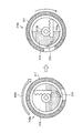
つぎに、図1に示すカプセル型内視鏡10について説明する。図2および図4は、図1に示すカプセル型内視鏡10の内部構造を示す模式図であり、図3は、図2に示すカプセル型内視鏡10の右側面図である。図2に示すように、カプセル型内視鏡10は、受信部3に無線信号を送信するアンテナ11、反射光を集光するレンズ12a、観察視野Fgに光を照射するLED12b、被検体の体腔内を撮像する撮像素子12、被検体内の所定部に注入される薬液を貯蔵する薬液タンク13、図示しない駆動部材の駆動によって薬液タンク13開口を開閉するバルブ14、モータなどを内蔵したアクチュエータ15、薬液タンク13内に貯蔵された薬液を被検体内の所望部位に注入するための針16、アンテナ11が受信した受信部3からの無線信号にしたがってカプセル型内視鏡10の各構成部位を制御する制御回路が構成された制御基板17、永久磁石18、およびカプセル型内視鏡10の各構成部位に電力を供給する電池19を有する。針16は、カプセル型内視鏡10の筐体の表面に対して突出および収納が可能である。そして、永久磁石18の磁化方向は、カプセル型内視鏡10を構成する筐体の長軸方向と略平行となるようにカプセル型内視鏡10内に設けられる。また、図3に示すように、LED12による光が観察視野Fgを照射できるように、カプセル型内視鏡10の撮像素子12側の筐体の先端は、透明部材で構成されている。
Next, the
アクチュエータ15と針16の後端とは接続している。そして、アクチュエータ15は、制御基板17の制御のもと、たとえば図2の左右方向に移動可能である。このため、アクチュエータ15が図2に示す状態から図4の矢印Y10aに示すように図4の右方向に移動した場合、針16は、図4の矢印Y10bに示すように、アクチュエータ15の動作にしたがって右方向に移動し、カプセル型内視鏡10外に突出する。針16がカプセル型内視鏡10外に突出した場合、針16の先端が観察視野Fg内に入るように針16のカプセル型内視鏡10内における設置位置、レンズ12aの設置位置、レンズ12aの集光能力、LED12bの照射範囲などが設定されている。このため、カプセル導入システム1のユーザは、表示部5に表示される撮像素子12によって撮像された画像を確認することによって、針16がカプセル型内視鏡10外に突出したか否かを判断することができるとともに、針の穿刺状態、薬液注入時の状態を確認することができる。
The
また、アクチュエータ15が図4に示す状態から図4の左方向に移動した場合、針16は、アクチュエータ15の動作にしたがって右方向に移動し、カプセル型内視鏡10内に収納されることとなる。このため、アクチュエータ15および制御基板17は、針16に対して突出動作および収納動作を行なわせることができる機能を有する。針16は、図2および図4に示すように、突出した針16の先端方向がカプセル型内視鏡10の長軸方向と略平行となるようにカプセル型内視鏡10内に設けられる。このため、針16は、カプセル型内視鏡10の長軸方向と略平行に突出または収納する。さらに、突出した針16の先端方向と永久磁石18の磁化方向とは、略平行となる。なお、アクチュエータ15は、電池19から供給された電力を用いて動作を行なう。
When the
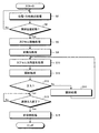
つぎに、図5を参照して、図1に示すカプセル導入システム1における薬液注入処理について説明する。図5は、図1に示すカプセル導入システム1における薬液注入処理を説明する処理手順を示すフローチャートである。
Next, with reference to FIG. 5, the chemical solution injection process in the
まず、図1に示すカプセル導入システム1においては、カプセル型内視鏡10が被検体内に取り込まれカプセル型内視鏡10と受信部3との通信処理が開始する。そして、受信部3は、カプセル型内視鏡10から送信される無線信号を処理して、カプセル型内視鏡10が撮像した画像を含む画像情報を順次制御部4に出力する。表示部5は、制御部4の制御のもと、カプセル型内視鏡10が撮像した画像を順次表示出力する。この場合、受信部3は、カプセル型内視鏡10から送信された無線信号を処理してカプセル型内視鏡10が撮像した画像を出力するとともに、カプセル型内視鏡10から送信された各無線信号の受信強度をもとに、カプセル型内視鏡10の被検体内における位置および方向を検出する位置・方向検出処理を行なう(ステップS2)。この受信部3による位置・方向検出処理の結果は、制御部4に出力され、表示部5は、制御部4の制御のもと、画像を表示するとともに、この表示画像を撮像したときのカプセル型内視鏡10の位置および方向を表示出力する。なお、カプセル型内視鏡10の撮像処理と表示部5の画像表示とは、ほぼリアルタイムで行なわれるとみなしてよいため、カプセル導入システム1のユーザは、表示部5に表示された画像の撮像位置にカプセル型内視鏡10が位置するものとして、診断や薬液注入などを指示することができる。
First, in the
次いで、制御部4は、入力部6から穿刺位置近傍である旨を示す指示情報を受信したか否かを判断する(ステップS4)。カプセル型内視鏡10のユーザは、表示部5に表示された画像、カプセル型内視鏡10の位置、方向を確認することによって、カプセル型内視鏡10が針16の穿刺位置近傍であると判断した場合、入力部6を操作し、穿刺位置近傍である旨を示す指示情報を入力する。制御部4が入力部6から穿刺位置近傍である旨を示す指示情報を受信しないと判断した場合(ステップS4:No)、受信部3は、カプセル型内視鏡10に対する位置・方向検出処理を再度行なう(ステップS2)。
Next, the control unit 4 determines whether or not instruction information indicating that it is near the puncture position is received from the input unit 6 (step S4). The user of the
これに対し、制御部4が入力部6から穿刺位置近傍である旨を示す指示情報を受信したと判断した場合(ステップS4:Yes)、カプセル導入システム1は、入力部6からの指示情報をもとにカプセル型内視鏡10をカプセル型内視鏡10が針16による穿刺直前にとるべき所望姿勢となるようにカプセル型内視鏡10の移動および方向を変更するカプセル移動処理を行なう(ステップS6)。具体的には、ユーザが入力部6を操作し、カプセル型内視鏡10を移動させる位置およびカプセル型内視鏡10の姿勢を指示する指示情報を入力する。入力部6は、カプセル型内視鏡10を移動させる位置およびカプセル型内視鏡10の姿勢を指示する指示情報を制御部4に入力し、磁界制御部8は、制御部4を介して入力された指示情報にしたがって、カプセル型内視鏡10が針16による穿刺直前にとるべき所望姿勢となるようにカプセル型内視鏡10の永久磁石18の位置および方向を変化させる磁界を磁界発生部2に発生させる。この場合、磁界制御部8は、カプセル型内視鏡10における永久磁石18の磁化方向、カプセル型内視鏡10における針16の位置、および針16の先端方向をもとに、カプセル型内視鏡10の永久磁石18の位置および方向を変化させる磁界を磁界発生部2に発生させる。また、磁界制御部8は、カプセル型内視鏡10が位置および方向を変化可能である強度の磁界を磁界発生部2に発生させる。このようにして、制御部4は、針16による穿刺直前にとるべき所望姿勢となるようにカプセル型内視鏡10全体の方向および位置を変化させる。
On the other hand, when it is determined that the control unit 4 has received the instruction information indicating that it is near the puncture position from the input unit 6 (step S4: Yes), the
つぎに、カプセル導入システム1は、カプセル型内視鏡10内の針16を突出させる針突出処理を行なう(ステップS8)。具体的には、ユーザが入力部6を操作し、針突出を指示する指示情報を入力する。入力部6は、針突出を指示する指示情報を制御部4に入力し、受信部3は、制御部4の制御のもと、針突出を指示する無線信号をカプセル型内視鏡10に送信する。そして、カプセル型内視鏡10においては、アンテナ11は、受信部3から送信された針突出を指示する無線信号を受信し、アクチュエータ15は、制御基板17の制御のもとアンテナ11が受信した指示信号にしたがって動作し、針16をカプセル型内視鏡10外に突出させる。
Next, the
そして、カプセル導入システム1は、突出した針16が穿刺対象層に穿刺できるようにカプセル型内視鏡10全体の方向を変化させるカプセル方向変化処理を行なう(ステップS10)。具体的には、ユーザが入力部6を操作し、カプセル型内視鏡10を変化させる方向を指示する指示情報を入力する。入力部6は、カプセル型内視鏡10の変化方向を指示する指示情報を制御部4に入力し、磁界制御部8は、制御部4を介して入力された指示情報にしたがって、カプセル型内視鏡10の永久磁石18の方向を変化させる磁界を磁界発生部2に発生させる。この場合、磁界制御部8は、カプセル型内視鏡10における永久磁石18の磁化方向、カプセル型内視鏡10における針16の位置、および針16の先端方向をもとに、カプセル型内視鏡10の永久磁石18の方向を変化させる磁界を磁界発生部2に発生させる。この結果、永久磁石18の方向変化にともなって、カプセル型内視鏡10全体の方向も変化させることができる。このようにして、カプセル導入システム1は、突出した針16が穿刺対象層に穿刺できるようにカプセル型内視鏡10全体の方向を変化させて、穿刺対象層に針16を穿刺する。
Then, the
次いで、カプセル導入システム1は、カプセル型内視鏡10の薬液タンク13を開栓する開栓処理を行ない(ステップS12)、針16を介して薬液タンク13内の薬液を対象となる領域に注入する。具体的には、ユーザが入力部6を操作し、薬液注入を指示する指示情報を入力する。入力部6は、薬液注入を指示する指示情報を制御部4に入力し、受信部3は、制御部4の制御のもと、バルブ14の開動作を指示する無線信号をカプセル型内視鏡10に送信する。そして、カプセル型内視鏡10においては、受信した無線信号にしたがって、バルブ14を開き、この結果、薬液タンク13内の薬液が針16を介して、対象となる領域に注入される。
Next, the
そして、制御部4は、薬液タンク13内の薬液が注入されているか否かを判断し(ステップS13)、薬液タンク13内の薬液が注入されていないと判断した場合には(ステップS13:No)、カプセル型内視鏡10の薬液タンク13を閉栓する閉栓処理を行なった後に(ステップS14)、ステップS10に戻ってカプセル方向変化処理を行なう。このように、薬液注入対象となる腸壁などに薬液が注入されていない場合には、一度カプセル型内視鏡10の薬液タンク13を開栓してから、改めてカプセル型内視鏡10の方向を変化させる処理を行なうことによって、より確実な注入が可能になる。そして、制御部4は、薬液タンク13内の薬液が注入されていると判断した場合には(ステップS13:Yes)、薬液注入時間などをもとに薬液注入が終了したか否かを判断する(ステップS15)。制御部4は、薬液注入が終了していないと判断した場合(ステップS15:No)、このステップS15を繰り返す。すなわち、制御部4は、薬液の注入が終了したと判断できるまでステップS15の判断処理を繰り返す。制御部4は、薬液注入が終了したと判断した場合(ステップS15:Yes)、バルブ14を閉じて突出した針16をカプセル型内視鏡10内に収納する針収納処理を行なう(ステップS16)。具体的には、受信部3は、バルブ14の閉動作および針収納を指示する無線信号をカプセル型内視鏡10に送信する。そして、カプセル型内視鏡10においては、受信した無線信号にしたがって、バルブ14が閉じられる。次いで、アクチュエータ15は、制御基板17の制御にしたがって動作し、針16をカプセル型内視鏡10内に収納する。このように、カプセル導入システム1においては、薬液の注入処理が行なわれる。
And the control part 4 judges whether the chemical | medical solution in the chemical |
つぎに、図5に示すカプセル方向変化処理について詳細に説明する。図6は、図2〜図4に示すカプセル型内視鏡10に対する方向変化処理を説明する図であり、カプセル型内視鏡10の長軸方向の長さよりも上下方向が広い胃などの空間を例に示す。図6(1)に示すように、磁界発生部2は、胃壁Ws表面と平行である向きの磁界M11をカプセル型内視鏡10に与え、胃壁Ws上のカプセル型内視鏡10を穿刺直前にとるべき所望姿勢とする。
Next, the capsule direction changing process shown in FIG. 5 will be described in detail. FIG. 6 is a diagram for explaining the direction changing process for the
その後、カプセル型内視鏡10においては、図6(1)に示すように針16が突出する。そして、磁界発生部2は、図6(2)の磁界M12に示すように、突出した針16の先端が胃壁Ws側を向くように、カプセル型内視鏡10に与えていた磁界の向きを斜め方向に変化させる。この結果、カプセル型内視鏡10内の永久磁石18の方向は、磁界M12の磁界方向にしたがって胃壁Wsに対し傾斜する方向に変化する。そして、永久磁石18の傾斜にともない、カプセル型内視鏡10全体の方向も傾斜し、カプセル型内視鏡10は胃壁Wsから後端部が持ち上がる状態となる。この場合、カプセル型内視鏡10のほぼ全体の重量が、胃壁Ws側を向いていた針16の先端にかかるため、針16の先端方向に大きな力がかかることになり、針16が胃壁Wsに穿刺される。
Thereafter, in the
次いで、図6(2)の矢印Y11に示すようにカプセル型内視鏡10の長軸と胃壁Ws表面とが平行になるように、傾斜させていた磁界M12の方向を図6(3)の磁界M13に示すように元に戻す。この結果、カプセル型内視鏡10内の永久磁石18の方向は、図6(3)に示すように、胃壁Wsと略平行となるように変化し、この永久磁石18の方向変化にともない、カプセル型内視鏡10の長軸方向が胃壁Wsと略平行となるように、カプセル型内視鏡10の方向が変化する。そして、胃壁Wsに刺さっていた針16も胃壁Wsと略平行となるように方向が変化する。この針16の方向変化によって、図6(3)の矢印Y12に示すように針16で胃壁Wsをすくい上げるような動作が可能となり、より確実に針16を胃壁Wsに刺すことが可能になる。その後、バルブ14が開かれ、薬液タンク13内の薬液が胃壁Ws内に注入される。
Next, the direction of the magnetic field M12 that is inclined so that the long axis of the
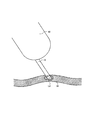
また、図7を参照して、カプセル型内視鏡10の外径と同程度の内径を有する小腸などの狭い空間における場合について説明する。この場合、磁界発生部2は、図6(1)と同様に、図7(1)に示すように、腸壁Wi表面と平行である向きの磁界M14をカプセル型内視鏡10に与え、腸壁Wi上のカプセル型内視鏡10を穿刺直前にとるべき所望姿勢とする。その後、カプセル型内視鏡10においては、針16が突出する。そして、磁界発生部2は、図7(2)の磁界M15に示すように、突出した針の先端が腸壁Wi側を向くように磁界の向きを斜め方向に変化させる。この結果、カプセル型内視鏡10内の永久磁石18の方向は、磁界M15の磁界方向にしたがって傾斜する方向に変化し、カプセル型内視鏡10全体の方向も傾斜する。そして、腸壁Wiに傾斜したカプセル型内視鏡10から張力が与えられ腸壁Wiが伸び広げられるとともに、領域S11のように伸展した腸壁Wiに針16が接触する。この場合、腸壁の弾性力(反力)が傾斜した針16の先端にかかるため、針16の先端方向に大きな力がかかることなり、針16が腸壁Wiに穿刺される。さらに、針16を重力方向に傾けた場合には、カプセル型内視鏡10と腸壁の重量とを針16の先端にかけることができる。
A case in a narrow space such as a small intestine having an inner diameter comparable to the outer diameter of the
次いで、図7(2)の矢印Y15に示すようにカプセル型内視鏡10が腸壁Wi上に平行となるように、傾斜させていた磁界M15の方向を図7(3)の磁界M16のように元に戻す。この結果、カプセル型内視鏡10内の永久磁石18の方向は、図7(3)に示すように、腸壁Wiと略平行となるように変化し、カプセル型内視鏡10の方向が元に戻る。そして、腸壁Wiに刺さっていた針16も腸壁Wiと略平行となるように方向が変化する。この針16の方向変化によって、図7(3)の矢印Y16に示すように針16で腸壁Wiをすくい上げるような動作が可能となり、より確実に針16を腸壁Wiに刺すことが可能になる。その後、バルブ14が開かれ、薬液タンク13内の薬液が腸壁Wi内に注入される。
Next, the direction of the magnetic field M15 that is inclined so that the
このように、実施の形態1においては、永久磁石18に与える磁界の向きを変化させてカプセル型内視鏡10全体の向きを変化させることによって、針16に大きな動きを与えることができるため、針16を穿刺対象層に確実に刺すことができる。また、実施の形態1においては、カプセル型内視鏡10の長軸方向(観察方向)とカプセル型内視鏡10内の永久磁石18の磁化方向とが一致するため、印加する磁界の方向にカプセル型内視鏡10の長軸方向を変化することができることから、発生させた磁界に対してカプセル型内視鏡10の長軸方向を一意に決定することができる。さらに、実施の形態1においては、針16の先端方向と磁化方向とが略平行であるため、印加した磁界の方向に針16を穿刺できることから、穿刺方向を一意に決定することができる。
As described above, in the first embodiment, the
なお、ユーザは、磁界を変化させる方向を、表示部5に表示された被検体内画像を見ながら指示してもよいし、受信部3によるカプセル型内視鏡10の位置・方向検出結果をもとに指示してもよい。ユーザは、被検体画像を見ながらカプセル型内視鏡10の方向を指示する場合には、針16を突出させていない状態で磁界を印加し、実際に発生させる磁界の方向を確認した後に、針16を突出させ磁界印加を指示してもよい。
Note that the user may instruct the direction of changing the magnetic field while viewing the in-vivo image displayed on the
また、胃などの広い空間では、当然ながらカプセル型内視鏡10の鉛直上には空間があり、カプセル型内視鏡10は、胃壁Wsの傾きが小さい(水平に近い)位置に、長軸方向が胃壁Ws表面と略平行となるように胃壁Ws上に安定に存在する。このため、鉛直である方向の磁界を印加した場合には、永久磁石18の磁化方向が鉛直方向となるように永久磁石18が立ち上がり、これにともないカプセル型内視鏡10も立ち上がることが確実であると考えられるため、ユーザは、カプセル型内視鏡10を立ち上げる場合には、単に鉛直である磁界を指示すればよい。
Also, in a wide space such as the stomach, there is naturally a space vertically above the
また、小腸などの狭い空間においては、図7(2)のように傾斜した磁界M15を印加しカプセル型内視鏡10の傾斜による張力を腸壁Wiにかけて腸壁Wiを十分に伸展させた後に、針16を突出してもよい。先に針16を突出させた後にカプセル型内視鏡10を傾斜させた場合には、カプセル型内視鏡10の傾斜の運動量や腸壁Wiのはね返りによって針16がカプセル型内視鏡10内に押し戻される場合も考えられる。このため、カプセル型内視鏡10を傾斜させて腸壁Wiを伸展させた後に針16を突出した場合には、さらに確実に針16を腸壁Wiに刺すことができるものと考えられる。
In a narrow space such as the small intestine, a magnetic field M15 inclined as shown in FIG. 7 (2) is applied, and the tension due to the inclination of the
また、実施の形態1においては、図6(2)および図6(3)または図7(2)および図7(3)に示すように、磁界発生部2によって印加される磁界の方向を変化させることによってカプセル型内視鏡10の方向を変化させた場合を例に説明したが、もちろんこれに限らない。たとえば、磁界制御部8は、カプセル型内視鏡10を傾斜させるために印加していた磁界M12,M15の印加を停止し、発生磁界を0にする。この場合には、傾斜していたカプセル型内視鏡10は、カプセル型内視鏡10自体の重みで胃壁Ws,Wi上に倒れ、この結果、胃壁Ws,Wiに先端が接していた針16がすくい上げられるように動作し、胃壁Ws,Wiに確実に穿刺される。このように、磁界発生部2が発生する磁界の強度を変化させることで永久磁石18の方向を変化させてカプセル型内視鏡10全体の方向を変化させてもよい。
In the first embodiment, the direction of the magnetic field applied by the
また、突出した場合における針16の先端方向と、針16が突出および収納する方向とが異なるように針16を設けて、針16の穿刺時における腸壁などからの反力によってアクチュエータ15が受ける影響を軽減してもよい。
In addition, the
具体的には、図8のカプセル型内視鏡10aに示すように、突出した場合における針16の先端方向がカプセル型内視鏡10aの長軸方向と略平行となるようにする。そして、矢印Y17に示すように、この針16がカプセル型内視鏡10aの長軸方向とは異なる突出方向でカプセル型内視鏡10a外に突出するように設定する。
Specifically, as shown in the
ここで、図6(2)または図7(2)に示す場合と同様に、傾斜した磁界が印加されることによってカプセル型内視鏡10a全体が傾斜した場合、カプセル型内視鏡10aによる張力に反して腸壁から撥ね返った反力P1がカプセル型内視鏡10aに加えられる。この反力P1は、傾斜した磁界方向に反するように、カプセル型内視鏡10aの長軸と平行である向きで撥ね返ってくる。図2〜図4に示すカプセル型内視鏡10においては、カプセル型内視鏡10の長軸方向と略平行に針16が移動するようにアクチュエータ15が設定されているため、図8に示すように針16の収納方向と同じ方向の反力P1が加えられた場合には、この反力P1によって突出していた針16がカプセル型内視鏡10内に押し戻される場合もあった。これに対し、カプセル型内視鏡10aにおいては、たとえば針16の先端方向と同じ方向の反力P1が加えられた場合であっても、針16が突出または収納する方向が反力P1と異なるため、針16の先端方向と針16の突出方向とが同じ場合と比較し、反力P1によって受ける影響が少なく、針16が押し戻されることがない。したがって、針16を適切に穿刺対象層に刺すことができる。
Here, as in the case shown in FIG. 6 (2) or FIG. 7 (2), when the
また、磁界発生部2は、磁界制御部8の制御のもと、図6(2)、図6(3)または図7(2)、図7(3)において針16を胃壁Wsまたは腸壁Wi内に刺すときに、磁界M12,M15の磁束密度を磁界方向に変化させて、磁界方向に磁気引力を生じさせてもよい。この場合、永久磁石18の磁化方向と針16の先端方向とが略平行であり、永久磁石18は磁気引力によって磁界方向に移動する。このため、針16は、磁気引力によって腸壁Wi,Wsに強く押し付けられる力を受け、胃壁Ws内に確実に刺さる。もちろん図9(1)に示すように針16の先端方向と永久磁石18の磁化方向とが厳密に平行でない場合も同様に、磁界発生部2は、磁界制御部8の制御のもと、磁束密度が磁界方向に変化する勾配磁界M17を永久磁石18に与え、矢印Y17aの方向の磁気引力を発生させて、カプセル型内視鏡全体の矢印Y17aの方向への移動によって針16を胃壁Wsに強く押し付けてもよい。図9に示す場合のように針16の先端方向と永久磁石18の磁化方向とが平行でない場合には、永久磁石18の磁化方向と平行な磁気引力が、針16の穿刺方向にかかるようにするためには、図9(2)に示す針16の先端方向と永久磁石18の磁化方向とが成す角の角度θ11が45°以下である必要がある。角度θ11が45°以下である場合には、図9(2)のように矢印Y17a方向の磁気引力が針16の穿刺方向にかかるため、矢印Y17bに示すように、針16は磁気引力によって胃壁Wsに押し付けられ、確実に刺さることができる。さらに、角度θ11が30°以下の場合には磁気引力の80%以上の成分を針16の穿刺方向に与えることができるため、角度θ11を30°以下にすることが望ましい。
In addition, the magnetic
ところで、一般的に、通常の注射針は、深く刺せるように、鋭い角度で2段階にわたってカットすることによって針の先端を鋭くしている。図10に示すように、たとえば針116の先端をまず約12°でカットしてから、図11に示すように、このカット面の斜め方向15°の角度でカットしている。これに対し、カプセル型内視鏡においては、腸壁や胃壁などが穿刺対象層であるため、通常の注射針のように深く刺す必要がない。カプセル型内視鏡においては、所定厚さの穿刺対象層に選択して針を確実に刺すことが要求される。このため、図12および図13に示すように、穿刺対象層に選択的に針16が確実に刺さるように、針16の先端は、通常の注射針の角度よりも大きい約30°の角度でカットされている。
By the way, in general, a normal injection needle is sharpened at the tip of the needle by cutting it at two angles at a sharp angle so that it can be deeply inserted. As shown in FIG. 10, for example, the tip of the
また、通常の注射針のように鋭い角度で2段階にわたってカットした場合、約30°でカットした図13の針16における吐出口面積S16よりも、図11の針116の吐出口面積S116に示すように面積が広い吐出口となる。さらに、図14に示すように、カット面が穿刺対象層の表面にほぼ垂直となるように針116が穿刺対象層である腸壁Wiに刺さった場合、吐出口面積が広いため、吐出口の一部しか穿刺対象層に刺さらない場合があった。この場合、薬液が穿刺対象層に刺さっていない部分から漏れてしまい、薬液を適切に穿刺対象層に注入することができなかった。
In addition, when cut at two angles at a sharp angle like a normal injection needle, the discharge port area S116 of the
このような薬液Ldの注入不良を改善するため、図15に示すように、針16のカット面が穿刺対象層の表面と略平行になるように針16をカプセル型内視鏡の筐体に設ければよい。針16のカット面は、従来の注射針よりも大きな角度でカットされているため、針16は、吐出口面積が穿刺対象層に適切に穿刺できるように設定される上、針16のカット面が穿刺対象層の表面と略平行になるようにカプセル型内視鏡の筐体に設けられていることから、カット面の吐出口すべてが穿刺対象層に刺さることが可能になり、薬液Ldを適切に穿刺対象層内に注入することができる。なお、針16のカット面が穿刺対象層の表面と略平行になるように針16をカプセル型内視鏡の筐体に設けるには、針16のカット面がカプセル型内視鏡10,10aの筐体に対して外側を向くようにすればよい。
In order to improve such poor injection of the drug solution Ld, as shown in FIG. 15, the
(実施の形態2)
つぎに、実施の形態2について説明する。図16は、実施の形態2におけるカプセル型内視鏡の内部構成を示す図である。なお、実施の形態2にかかるカプセル導入システムは、図1と同様の構成を有し、図5に示す処理手順と同様の処理手順を行なうことによって、薬液の注入を行なうことができる。(Embodiment 2)
Next, a second embodiment will be described. FIG. 16 is a diagram illustrating an internal configuration of the capsule endoscope according to the second embodiment. Note that the capsule introduction system according to the second embodiment has the same configuration as that in FIG. 1, and can perform the injection of the chemical solution by performing the same processing procedure as that shown in FIG.
実施の形態2にかかるカプセル導入システムにおいては、図16に示すように、カプセル型内視鏡を構成する筐体の径方向と磁化方向が略平行となる永久磁石218を有するカプセル型内視鏡210を使用する。カプセル型内視鏡210の径方向とカプセル型内視鏡210内の永久磁石218の磁化方向とが一致するため、印加する磁界の方向にカプセル型内視鏡210の径方向を変化させることができる。このため、カプセル型内視鏡210に回転磁界を与えた場合には、回転磁界の回転にしたがってカプセル型内視鏡210も回転することとなる。
In the capsule introduction system according to the second embodiment, as shown in FIG. 16, a capsule endoscope having a
また、針16の先端方向は径方向と略並行であり、針16は、アクチュエータ15の駆動にしたがってカプセル型内視鏡210の径方向に突出または収納する。したがって、永久磁石18の磁化方向と針16の先端方向とは略平行となる。針16の先端方向と磁化方向とが略平行であるため、印加した磁界の方向に針16を穿刺できることから、穿刺方向を一意に決定することができる。なお、針16は、針16の先端方向がカプセル型内視鏡210の筐体の長軸に垂直な平面と略平行に設けられることとなる。
Further, the distal end direction of the
つぎに、カプセル型内視鏡210を使用した場合におけるカプセル方向変化処理について詳細に説明する。たとえば、図17に示すように狭い空間における場合について説明する。この場合、磁界発生部2は、図17(1)に示すように、腸壁Wi内の穿刺対象位置に針位置を合わせるための回転磁界M21aをカプセル型内視鏡210に与え、カプセル型内視鏡210を穿刺直前にとるべき所望姿勢とする。
Next, the capsule direction changing process when the
その後、カプセル型内視鏡210においては、針16が突出する。そして、磁界発生部2は、磁界の向きを斜め方向に変化させた磁界M21bをカプセル型内視鏡210に与える。すなわち、磁界発生部2は、磁界制御部8の制御のもと、突出した針16の先端が穿刺対象層側を向くように、永久磁石18を傾斜させる磁界を発生して、カプセル型内視鏡210全体を傾斜させる。この結果、カプセル型内視鏡210内の永久磁石218の方向は、磁界M21bの磁界方向にしたがって斜めに変化し、図17(2)の矢印Y21に示すように、カプセル型内視鏡210全体の方向も傾斜する。そして、腸壁Wiに傾斜したカプセル型内視鏡210から張力が与えられ腸壁Wiが伸び広げられるとともに、伸展した腸壁Wiに接触していた針16の先端に腸壁の弾性力(反力)がかかるため、針16の先端方向に大きな力がかかることとなり、針16が腸壁Wiに確実に穿刺される。さらに、針16を重力方向に傾けた場合は、カプセル型内視鏡210と腸壁の重力とを針16の先端にかけることができる。なお、実施の形態2においては、針16を突出させた後に磁界M21aの方向を変えるほか、磁界M21aの方向を変えてカプセル型内視鏡210を傾斜した後に針16を突出させてもよい。
Thereafter, in the
したがって、実施の形態2のように永久磁石218の磁化方向と針16の先端方向とをカプセル型内視鏡の径方向に略平行に設けた場合においても、永久磁石218に与える磁界の向きを変化させることによって、カプセル型内視鏡210全体の向きの変化による大きな動きを針16に与えて針16を穿刺対象層に確実に刺すことができる。
Therefore, even when the magnetization direction of the
なお、広い空間においては、図18(1)に示すように、まず、磁界発生部2は、胃壁Wsと平行である磁界M22をカプセル型内視鏡210aに与える。この場合、カプセル型内視鏡210a内の永久磁石218の方向が磁界M22の磁界方向にしたがって変化することにともない、カプセル型内視鏡210aの長軸が胃壁Wsと垂直になるように方向が変化する。すなわち、カプセル型内視鏡210aは、胃壁Ws上に立つような姿勢になる。また、針16の先端は、この磁界M22と同じ方向を向くように突出する。そして、磁界発生部2は、図18(2)に示すように、突出した針16の先端方向と同じ方向の磁界M22ではなく、胃壁Ws方向へ向かう矢印Y22にしたがって方向を徐々に変化させた磁界M23a,M23b,M23cを順次カプセル型内視鏡210aに与える。この結果、永久磁石218が矢印Y22にしたがって方向を変化させ、これにともないカプセル型内視鏡210aも矢印Y22のように針16が突出した側に倒れる。このカプセル型内視鏡210aが倒れることによる運動量によって、針16を穿刺対象層に確実に刺すことが可能になる。
In a wide space, as shown in FIG. 18A, first, the
また、カプセル型内視鏡210aに示すように、カプセル型内視鏡210aを立たせた時に胃壁Ws側にしたい面S(図18(1)においてはカプセル型内視鏡210aの下側の面となる。)を平坦にし、さらに面S側に錘220を設けて、カプセル型内視鏡210aを所望の向きで安定して胃壁Ws上に立たせるようにしてもよい。また、図18のように錘220を新たに設けるほか、カプセル型内視鏡210aを立たせた時に胃壁Ws側にしたい面S側に永久磁石218を設けることによって錘としての機能を持たせてもよい。
Further, as shown in the
また、実施の形態2においては、実施の形態1と同様に、胃壁Ws,Wi内に刺すときに磁気引力を発生させて、この磁気引力を針16に加えて針を刺してもよい。この場合、磁界発生部2は、磁束密度を磁界方向に変化させた磁界をカプセル型内視鏡210に与える。この結果、永久磁石218の磁化方向に磁気引力が生じ、この磁気引力によって、針16を穿刺することができる。
In the second embodiment, similarly to the first embodiment, a magnetic attractive force may be generated when piercing the stomach walls Ws and Wi, and the magnetic attractive force may be applied to the
また、磁界発生部2は、磁束密度を磁界方向に変化させるほか、磁束密度を磁界方向と垂直方向に変化させた勾配磁界をカプセル型内視鏡に与えてもよい。たとえば、図19(1)に示すように、永久磁石218の磁化方向の垂直方向に磁束密度が変化した磁界M24を与えた場合である。この場合、図19(1)の矢印Y24aの方向に磁気引力が生じ、この磁気引力にしたがってカプセル型内視鏡210bも矢印Y24aの方向に移動する。これにともない、カプセル型内視鏡210bから突出していた針16も矢印Y24bの方向に移動する。なお、カプセル型内視鏡210bにおいては、針16をすくい上げるように穿刺するため、針16の先端方向と永久磁石218の磁化方向とを略平行とはしていない。永久磁石18の磁化方向と垂直である磁気引力が針16の穿刺方向にかかるようにするため、図19(2)に示すように、針16の先端方向と永久磁石218の磁化方向とが成す角の角度θ21が45°以上となるように、針16を設けている。角度θ21を45°以上とした場合には、図19(2)に示すように、針16の穿刺方向に矢印Y24aの方向の磁気引力がかかるようになるため、矢印Y24bの方向に針16が胃壁Wsに押し付けられて確実に刺さる。さらに、角度θ21が60°以上の場合には磁気引力の80%以上の成分を針16の穿刺方向に与えることができるため、角度θ21を60°以下にすることが望ましい。
In addition to changing the magnetic flux density in the magnetic field direction, the
また、図8のカプセル型内視鏡10aと同様に、図20(1)のカプセル型内視鏡210cのように、突出した場合における針16の先端方向と、矢印Y25aに示す針16が突出または収納する方向とが異なるように針16を設けてもよい。図20(2)に示すように、カプセル型内視鏡210cが倒れて針16が胃壁Wsに穿刺される場合、カプセル型内視鏡210cには、針16の矢印Y26に示す収納方向とは異なる向きの反力P26が胃壁Wsにかかるため、針16がカプセル型内視鏡210c内に押し戻されることはない。
Similarly to the
さらに、図20(1)に示すように、永久磁石218をカプセル型内視鏡210cの径方向に対し傾くように設けてもよい。この場合、鉛直方向の磁界M25が印加された場合、永久磁石218が磁界M25と同じ方向となるように方向を変化させるため、カプセル型内視鏡210c本体は、胃壁Wsに対して傾斜するように立ち上がることとなる。そして、針16は、カプセル型内視鏡210c本体が胃壁Wsから立ち上がったときに、カプセル型内視鏡210cの胃壁Ws側の傾斜面から突出するように設けられる。これによって、磁界M25が印加された場合には針16の先端が確実に胃壁Wsに向くように位置決めできる。そして、磁界M25の印加が停止された場合、傾いたカプセル型内視鏡210c自体の重みによって、矢印Y25bのようにカプセル型内視鏡210cが針16を下にした状態のまま倒れ、確実に針16を胃壁Wsに刺すことができる。
Further, as shown in FIG. 20A, the
(実施の形態3)
つぎに、実施の形態3について説明する。図21は、実施の形態3におけるカプセル型内視鏡の内部構成を示す図である。また、図22は、図21におけるCC断面図である。なお、実施の形態3にかかるカプセル導入システムは、図1と同様の構成を有し、図5に示す処理手順と同様の処理手順を行なうことによって、薬液の注入を行なうことができる。(Embodiment 3)
Next, a third embodiment will be described. FIG. 21 is a diagram illustrating an internal configuration of the capsule endoscope according to the third embodiment. FIG. 22 is a CC cross-sectional view in FIG. Note that the capsule introduction system according to the third embodiment has the same configuration as that in FIG. 1, and can perform the injection of the chemical solution by performing the same processing procedure as the processing procedure shown in FIG.
実施の形態3にかかるカプセル導入システムにおいては、図21に示すように、カプセル型内視鏡210と同様に、筐体の径方向と磁化方向が略平行となる永久磁石318を有するカプセル型内視鏡310を使用する。
In the capsule introduction system according to the third embodiment, as shown in FIG. 21, in the capsule-type endoscope having the
そして、図21および図22に示すように、アクチュエータ15は、針316の後端と、90°以上135°以下の角度を成すように接続する。このため、アクチュエータ15が図22(2)の矢印Y31のようにカプセル型内視鏡310の外周側に移動した場合、針316は、矢印Y32に示すようにカプセル型内視鏡310の外表面に突出する。したがって、突出した場合における針316の先端方向と針316が突出または収納する方向とが異なるため、カプセル型内視鏡310の矢印Y31方向への移動により腸壁などから反力P31を受けた場合であっても、突出していた針316がカプセル型内視鏡310に押し戻されることはない。
As shown in FIGS. 21 and 22, the
このカプセル型内視鏡310においては、カプセル型内視鏡310の径方向とカプセル型内視鏡310内の永久磁石318の磁化方向とが一致するため、印加する磁界の方向にカプセル型内視鏡310の径方向を変化させることができる。具体的には、図23(1)〜(3)に示す磁界M31〜M33のように管腔を中心とする回転磁界が与えられた場合には、矢印Y33a,Y33b,Y33cのように永久磁石318も回転磁界の回転にしたがってカプセル型内視鏡310の長軸を中心に回転し、これにともない、カプセル型内視鏡310全体も矢印Y33のように回転する。この場合、突出していた針316もカプセル型内視鏡310全体の回転にともなって移動するため、図23(3)に示すように、針316の先端部に引っかかった腸壁Wiが伸展され、カプセル型内視鏡310全体の回転による運動量が針316の先端にかかって針316は腸壁Wi内に確実に刺さる。
In this
または、磁界発生部2は、図24(1)に示すように、管腔に対し斜めの磁界M34を印加してカプセル型内視鏡310本体を傾かせることによって図24(2)のように腸壁Wiを伸展させたうえで、磁界M34と同じ角度を持つとともにカプセル型内視鏡310の外周に沿って回転する回転磁界M35を印加してもよい。この回転磁界M35の回転にしたがって、矢印Y35に示すようにカプセル型内視鏡310も回転するため、カプセル型内視鏡310の外表面に突出した針316は、伸展した腸壁Wiに確実に刺さる。
Alternatively, as shown in FIG. 24 (1), the
このように、実施の形態3のように針316をカプセル型内視鏡310の外表面に突出させる場合も、永久磁石318に与える磁界の向きを変化させることによって、カプセル型内視鏡310全体の向きの変化による大きな動きを針316に与えて針316を穿刺対象層に確実に刺すことができる。
As described above, when the
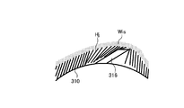
ここで、針316の先端が腸壁などの穿刺対象層の組織に引っかかった後に回転磁界によってカプセル型内視鏡310が回転することによって、針316を確実に穿刺できる。しかしながら、図25(1)に示すように、針の突出長さが短く針116の先端が腸壁Wiなどの穿刺対象層の組織に引っかからなかった場合には、カプセル型内視鏡全体が回転した場合であっても、図25(2)に示すように、針116の先端が腸壁Wiの組織表面で滑って空転してしまい、針116が刺さらない。このため、針316の先端が穿刺対象層の組織に引っかかるように、針316の突出長さや針316の配設位置を設定する必要がある。
Here, after the tip of the
具体的には、図26(1)に示すように、領域S33aにおいて針316の先端に腸壁Wiが引っかかり、矢印Y37に示すようにカプセル型内視鏡310の回転によって腸壁Wiが伸展できるように、図26(2)の領域S33bに示すように、針316の先端とカプセル型内視鏡310の筐体との間に、腸壁Wiの組織が十分に入り込める空間が必要となる。
Specifically, as shown in FIG. 26 (1), the intestinal wall Wi is caught at the tip of the
たとえば、ヒトの小腸を針の穿刺対象層とした場合を例に針316の具体的構造および設置位置条件についてさらに詳細に説明する。図27に示すように、小腸の粘膜層Wisは、内腔に向かって伸びる細長い毛状の絨毛Hjと呼ばれる組織から成り立つ。この絨毛Hjの長さは、1mm程度である。薬液を注入したい粘膜下層は、この絨毛Hjの根元部に当たる。このため、図28に示すように、針316の先端とカプセル型内視鏡310の外周の中心を結ぶ直線L0上で、針316の先端部とカプセル型内視鏡310の筐体との間に1mmを超える空間ができるように針316の構造および設置位置を設定すれば、この空間内に絨毛Hjが入り込み、針316の先端部が目標とする粘膜下層に到達することができる。針316の先端部が粘膜下層に到達している状態でカプセル型内視鏡310全体をカプセル型内視鏡310の長軸を中心に回転させることによって、針316が粘膜下層に穿刺され、薬液の注入が可能になる。
For example, the specific structure and installation position conditions of the
つぎに、針316の先端とカプセル型内視鏡310の外周の中心を結ぶ直線L0上で、針316の先端部とカプセル型内視鏡310の筐体との間に1mmを超える空間ができる針316の突出角度について説明する。この針316の突出角度を、図29に示すように、針316のカプセル型内視鏡310の筐体側である下側の母線と、この母線がカプセル型内視鏡310の筐体外周と交わる点における接線Lsとが成す角度をθとする。カプセル型内視鏡310が長軸を中心として回転した場合、図30に示すように、針316の先端において、上述した接線Lsと略平行な方向に小腸組織からの力Fを受ける。このうち、針316の移動方向と平行である力Fの成分が針316における小腸組織への穿刺力F´となる。針316の突出角度は、上述した母線と接線Lsとが成す角度θであるため、穿刺力F´の大きさは、Fcosθとなる。ここで、角度θが45°以下である場合には、穿刺力F´に垂直である力Fの一方の成分よりも穿刺力F´の方が大きくなるため、カプセル型内視鏡310の回転によって発生する力を効率的に穿刺に使用することができる。したがって、針316の突出角度θは、45°以下であることが望ましい。
Next, a space exceeding 1 mm is formed between the distal end portion of the
次いで、針316の突出長さLの最小値について説明する。図31のように、針316を含むカプセル型内視鏡310の長軸方向に垂直である断面を求め、カプセル型内視鏡310の長軸を原点とし、座標系を当てはめる。カプセル型内視鏡310の外径を2r、針316の先端部に対応する点をTとする。
Next, the minimum value of the protrusion length L of the
図32に示すように、針316の突出角度θおよび針316の突出長さLとした場合、点Tは、(Lcosθ,Lsinθ+r)の座標となる。この場合、針316の先端部とカプセル型内視鏡310筐体との間の長さである針下長さUは、以下の(1)式で表される。
U=((Lcosθ)2+(Lsinθ+r)2)1/2−r (1)As shown in FIG. 32, when the protrusion angle θ of the
U = ((L cos θ) 2 + (L sin θ + r) 2 ) 1/2 −r (1)
針下長さUは、前述したように1mm以上であればよいので、U≧1が成り立つ。このため、(1)式をもとに、以下の(2)式が導かれる。
L2+2rLsinθ−(2r+1)≧0 (2)Since the under needle length U may be 1 mm or more as described above, U ≧ 1 holds. Therefore, the following equation (2) is derived based on the equation (1).
L 2 + 2rLsin θ− (2r + 1) ≧ 0 (2)
図32により、突出長さLが同じ場合には、突出角度θが大きいほど針下長さUも大きくなる。言い換えると、突出角度θが大きいほどU≧1を満たす長さLが短くなる。突出角度θは、45°以下が望ましいため、突出角度θが45°であるときに、突出長さLが最小値となる。ここで、θ=45°を(2)式に代入すると、以下の(3)式が求められる。
L2+21/2rL−(2r+1)≧0 (3)
この(3)式を変形すると、(4)式が得られる。
(L+21/2r/2)2+(r2/2+2r+1)≧0 (4)According to FIG. 32, when the protruding length L is the same, the under needle length U increases as the protruding angle θ increases. In other words, the larger the protrusion angle θ, the shorter the length L that satisfies U ≧ 1. Since the protrusion angle θ is desirably 45 ° or less, the protrusion length L becomes the minimum value when the protrusion angle θ is 45 °. Here, if θ = 45 ° is substituted into the equation (2), the following equation (3) is obtained.
L 2 +2 1/2 rL− (2r + 1) ≧ 0 (3)
When this equation (3) is modified, equation (4) is obtained.
(L + 2 1/2 r / 2 ) 2 + (
この(4)式において、X=L+21/2r/2、P=r2/2+2r+1とすると、以下の(5)式となる。
X2−P=(X+P1/2)(X−P1/2)≧0 (5)
r>0であるため、P>0を導くことができる。In equation (4), when X = L + 2 1/2 r / 2, and P =
X 2 −P = (X + P 1/2 ) (X−P 1/2 ) ≧ 0 (5)
Since r> 0, P> 0 can be derived.
したがって、P1/2>0が成り立つため、(5)式が成り立つXの範囲は、P1/2≦Xである。これに、X=L+21/2r/2、P=r2/2+2r+1を当てはめることによって、以下の(6)式が成り立つ。
L+21/2r/2≧(r2/2+2r+1)1/2 (6)
そして、(6)式より、Lの最小値であるLminは、以下の(7)式のようになる。
Lmin=(r2/2+2r+1)1/2―21/2r/2 (7)
rの値が小さいほどU≧1を満たすLの最小値Lminも小さくなる。Therefore, since P 1/2 > 0 holds, the range of X in which equation (5) holds is P 1/2 ≦ X. Thereto, by fitting the X = L + 2 1/2 r / 2, P =
L + 2 1/2 r / 2 ≧ (
From the equation (6), L min which is the minimum value of L is expressed by the following equation (7).
L min = (r 2/2 + 2r + 1) 1/2 -2 1/2 r / 2 (7)
The smaller the value of r, the smaller the minimum L value L min that satisfies U ≧ 1.
小腸用のカプセル型内視鏡310は、外径が5mm以上であることが一般的であるため、R≧5とすると、rの最小値は、2.5mmとなる。このrの最小値2.5mmを(7)式に当てはめることによって、以下の(8)式のようにLminの値を決定することができる。
L≒1.253〔mm〕 (8)
このように、針316の突出長さLの最小値は、1.253mmとなる。したがって、突出長さLが1.26mmよりも長ければ、針316とカプセル型内視鏡310の筐体との間に絨毛Hjの長さ1mmを超えた高さの空間を形成することができる。Since the
L ≒ 1.253 [mm] (8)
Thus, the minimum value of the protrusion length L of the
なお、カプセル型内視鏡310の最大径は、被検体内への挿入性を考慮すると、20mm以下であることが望ましい。また、カプセル型内視鏡310の筐体の径が小さいほうが、針316と筐体との間に形成される空間の高さが1mmを超えるため、針316の突出長さLを小さくすることができ、この針316の突出および収納を駆動するアクチュエータ15をより小型化することが可能になる。
Note that the maximum diameter of the
(変形例1)
つぎに、本発明にかかるカプセル型内視鏡の変形例1について説明する。上述した実施の形態3にかかるカプセル型内視鏡310では、アクチュエータ15の駆動によって針316を突没していたが、この針316は、永久磁石318の回転によって突没してもよい。図33は、本発明の変形例1にかかるカプセル型内視鏡の一構成例を示す模式図である。図34は、図33に示すカプセル型内視鏡のCC断面図である。なお、図34には、この変形例1にかかるカプセル型内視鏡310aの要部である針316の突没機構部分が図示されている。(Modification 1)
Next, a first modification of the capsule endoscope according to the present invention will be described. In the
図33,34に示すように、この変形例1にかかるカプセル型内視鏡310aは、上述した実施の形態3にかかるカプセル型内視鏡310と同様の構造を有するカプセル型の筐体311の内部に、永久磁石318の回転力によって針316を突没する突没機構312と、突没機構312および永久磁石318を支持する回転軸313と、この回転軸313を回転自在に支持する軸受け部314と、筐体311に対する永久磁石318の接続状態を切り替える接続状態切替部315とを備える。また、針316は、特に図示しないが、チューブ等を介してバルブ14と連通する。その他の構成は実施の形態3と同じであり、同一構成部分には同一符号を付している。
As shown in FIGS. 33 and 34, the
突没機構312は、筐体311に対する相対的な永久磁石318の回転によって筐体311から針316を突没するための機構であり、図33,34に示すように、互いにかみ合うラック312aおよびピニオンギア312bを組み合わせて実現される。ラック312aは、ピニオンギア312bとかみ合う歯を備えた棒状部材である。このラック312aの端部には、上述した実施の形態3の場合と同様に傾斜した状態の針316が固定される。この場合、針316は、その先端方向が永久磁石318の磁化方向と同一面内となるように設けられる。かかるラック312aは、ピニオンギア312bの回転運動を直線運動に変換して、筐体311から針316を突出し、突出状態の針316を筐体311の内部に収納する。ピニオンギア312bは、回転軸313の端部に固定され、ラック312aとかみ合うように配置される。ピニオンギア312bは、回転軸313を介して永久磁石318の回転動作をラック312aに伝える。
The projecting and
回転軸313は、図33に示すように、永久磁石318の略中央部に形成された貫通穴に挿入した状態で永久磁石318に対して固定される。また、回転軸313の一端部には、上述したようにピニオンギア312bが取り付けられ、回転軸313の他端部は、軸受け部314に取り付けられる。軸受け部314は、図33に示すように筐体311の内壁側延出部に配置され、この回転軸313の他端部を回転自在に支持する。
As shown in FIG. 33, the
接続状態切替部315は、筐体311に対する永久磁石318の接続状態を切り替えるためのものであり、可動式の接続部材315aと、この接続部材315aの駆動源であるアクチュエータ315bとを用いて実現される。接続部材315aは、図33に示すように筐体311の内壁側延出部に配置される。接続部材315aは、回転軸313を介して永久磁石318を筐体311に対して接続し、この筐体311に対する永久磁石318の接続状態を固定状態と可動自在状態とに切り替える。具体的には、接続部材315aは、アクチュエータ315bの駆動力をもとに回転軸313に近づく方向に動作して、回転軸313を側方から挟持する(図33参照)。この結果、接続部材315aは、この回転軸313を介して永久磁石318を筐体311に対して固定状態にする。また、接続部材315aは、アクチュエータ315bの駆動力をもとに回転軸313から離間する方向に動作して、この回転軸313の挟持状態を解除する。この結果、接続部材315aは、かかる筐体311に対する永久磁石318の固定状態を解除して、筐体311に対して永久磁石318を可動自在状態にする。アクチュエータ315bは、上述した制御基板17の制御回路によって駆動制御される。
The connection
ここで、かかる筐体311に対する永久磁石318の固定状態とは、永久磁石318が回転軸313を介して相対的に筐体311に固定された状態である。図35は、筐体に対する永久磁石の接続状態が固定状態である場合のカプセル型内視鏡の動作を例示する模式図である。筐体311に対して固定状態の永久磁石318は、図35に示すように、外部から印加された磁界M36に追従して筐体311とともに回転する。カプセル型内視鏡310aは、かかる筐体311に対して固定状態の永久磁石318の回転に追従して、例えば筐体311の周方向に回転する。この場合、永久磁石318は筐体311に対して相対的に回転しないため、ラック312aおよびピニオンギア312bは動作せず、この結果、カプセル型内視鏡310aは、筐体311から針316を突没させない。
Here, the fixed state of the
一方、かかる筐体311に対する永久磁石318の可動自在状態とは、永久磁石318が筐体311に対して相対的に回転自在な状態である。図36は、筐体に対する永久磁石の接続状態が接続部材によって可動自在状態に切り替わった状態を示す模式図である。図37は、筐体に対する永久磁石の接続状態が可動自在状態である場合のカプセル型内視鏡の動作を例示する模式図である。図36,37に示すように、筐体311に対して可動自在状態の永久磁石318は、外部から印加された磁界M36に追従して、筐体311に対して相対的に回転する。この場合、永久磁石318は、回転軸313を介してピニオンギア312bに回転動作を伝える。ピニオンギア312bは、かかる永久磁石318の回転に伴って回転する。ラック312aは、かかるピニオンギア312bの回転動作を直線動作に変換して、図37に示すように筐体311から針316を突出させる。その後、かかる可動自在状態の永久磁石318に対して磁界M36と反対方向の回転磁界が印加された場合、この永久磁石318は、この反対方向の回転磁界に追従して、筐体311に対して相対的に回転する。この場合、永久磁石318は、回転軸313を介してピニオンギア312bに反対方向の回転動作を伝える。ピニオンギア312bは、かかる永久磁石318の回転に伴って反対方向に回転する。ラック312aは、かかるピニオンギア312bの回転動作を直線動作に変換して、突出状態の針316を筐体311に収納する。
On the other hand, the movable state of the
なお、かかる針316の突没動作時において、永久磁石318は筐体311に対して回転自在な状態であるため、カプセル型内視鏡310aは、かかる状態の永久磁石318の回転動作に追従せず、回転しない。
Since the
このように、本発明の変形例1では、筐体に対する永久磁石の接続状態を接続部材によって固定状態と可動自在状態とに切り替えるようにし、筐体に対する永久磁石の接続状態を固定状態にした場合、この固定状態の永久磁石の回転に追従してカプセル型内視鏡が回転し、筐体に対する永久磁石の接続状態を可動自在状態にした場合、筐体に対して相対的な永久磁石の回転に追従して針の突没機構を動作させて、筐体から針を突没するように構成した。このため、外部磁界の印加によってカプセル型内視鏡の磁気誘導と針の突没動作とを選択的に分けて実行することができ、この結果、カプセル内視鏡の磁気誘導および針の突没動作に必要な消費エネルギーを低減することができる。 As described above, in the first modification of the present invention, the connection state of the permanent magnet to the housing is switched between the fixed state and the movable state by the connection member, and the connection state of the permanent magnet to the housing is set to the fixed state. When the capsule endoscope rotates following the rotation of the fixed permanent magnet, and the permanent magnet is connected to the casing in a movable state, the permanent magnet rotates relative to the casing. The needle projecting and retracting mechanism is operated following the above, and the needle is projecting and retracting from the housing. For this reason, the magnetic guidance of the capsule endoscope and the projecting and retracting operation of the needle can be selectively performed by applying an external magnetic field. As a result, the magnetic guidance of the capsule endoscope and the projecting and retracting of the needle are performed. Energy consumption required for operation can be reduced.
なお、この変形例1にかかるカプセル型内視鏡310aは、筐体311の外表面に螺旋構造体を備え、筐体311に対して固定状態の永久磁石318の回転によって推進するように構成してもよい。また、この変形例1における針316の突没機構312は、上述したラック312aおよびピニオンギア312bを組み合わせたものに限らず、カムを用いたものであってもよいし、ベルトおよびプーリを組み合わせたものであってもよいし、クランク機構を用いたものであってもよい。
Note that the
(実施の形態4)
つぎに、実施の形態4について説明する。図38は、実施の形態4におけるカプセル型内視鏡の内部構成を示す図である。実施の形態4にかかるカプセル導入システムは、図1と同様の構成を有し、図5に示す処理手順と同様の処理手順を行なうことによって、薬液の注入を行なうことができる。(Embodiment 4)
Next, a fourth embodiment will be described. FIG. 38 is a diagram illustrating an internal configuration of the capsule endoscope according to the fourth embodiment. The capsule introduction system according to the fourth embodiment has the same configuration as that in FIG. 1, and can perform the injection of the chemical liquid by performing the same processing procedure as the processing procedure shown in FIG.
図38に示すように、実施の形態4にかかるカプセル導入システムにおいては、カプセル型内視鏡10と同様に、筐体の長軸方向と磁化方向が略平行となる永久磁石18を有するカプセル型内視鏡410を使用する。そして、針16の先端方向は径方向と略並行であり、針16は、アクチュエータ15の駆動にしたがってカプセル型内視鏡410の径方向に突出または収納する。したがって、永久磁石18の磁化方向と針16の先端方向とは、ほぼ垂直となる。
As shown in FIG. 38, in the capsule introduction system according to the fourth embodiment, similar to the
さらに、カプセル型内視鏡410の針16の先端方向側に錘220が設けられている。錘220は、カプセル型内視鏡410の長軸から、針16の先端方向側にずれた位置に設けられている。このため、錘220によって、カプセル型内視鏡410の筐体の重心は、カプセル型内視鏡410の筐体の長軸からずれることとなり、カプセル型内視鏡410の筐体の重心は、針16の先端方向側となる。言い換えると、針16の先端方向は、この錘220によってずれたカプセル型内視鏡410の筐体の重心がずれた方向、すなわち、重心における中心軸からのずれ方向に対応した方向となる。
Furthermore, a
つぎに、カプセル型内視鏡410を使用した場合におけるカプセル方向変化処理について詳細に説明する。たとえば、図39に示すように、下方に胃壁Wsがある広い空間における場合について説明する。この場合、磁界発生部2は、図39(1)に示すように、胃壁Wsの表面と並行である方向の磁界M41aをカプセル型内視鏡410に与える。この結果、永久磁石18の方向が磁界M41aにしたがって変化し、これにともないカプセル型内視鏡410の方向も変化する。そして、カプセル型内視鏡410は、カプセル型内視鏡410内の錘220によって、この錘220が下方の胃壁Ws側に向くように位置決めされる。つぎに、磁界発生部2は、図39(2)に示すように、胃壁Wsの上を向く磁界M41bをカプセル型内視鏡410に与え、永久磁石18の方向を変えてカプセル型内視鏡410を立ち上げる。次いで、磁界発生部2は、図39(3)の矢印Y41に示すように、胃壁Wsの上方から胃壁Ws側に方向を変化させた磁界M42a,M42b,M42cをカプセル型内視鏡410に与える。
Next, the capsule direction changing process when the
この結果、矢印Y42に示すように、カプセル型内視鏡410は、与えられていた磁界の方向の変化にしたがって胃壁Ws側に倒れ、倒れるカプセル型内視鏡410全体の重さが針16の先端にかかることによって突出していた針16が胃壁Wsに刺さる。この場合、カプセル型内視鏡410は、錘220が設けられた側を下側にして倒れるため、この錘220が設けられた側に対応して設けられた針16は、胃壁Wsに確実に穿刺することとなる。さらに、錘220を設けてカプセル型内視鏡410の重心を長軸から針の先端方向側へずらすことによって、カプセル型内視鏡410が倒れるときの運動量を大きくすることができるため、針16の穿刺をさらに確実化することができる。
As a result, as shown by the arrow Y42, the
このように、実施の形態4においては、錘220を設けてカプセル型内視鏡410の重心を突出した針16の先端方向側にずらすことによって、穿刺対象層への針16の穿刺をさらに確実化している。
As described above, in the fourth embodiment, by providing the
なお、本実施の形態4においては、図39(3)において、磁界発生部2は、磁界の印加を停止して発生磁界を0にして、カプセル型内視鏡410自体の重みでカプセル型内視鏡410を倒してもよい。この場合も同様に、錘220が設けられた側を下側にして倒れるため、この錘220が設けられた側に対応して設けられた針16は、胃壁Wsに確実に穿刺することとなる。
In the fourth embodiment, in FIG. 39 (3), the magnetic
また、本実施の形態4においては、図40に示すカプセル型内視鏡410aのように、永久磁石18の位置をカプセル型内視鏡410aの先端方向にずらしてもよい。また、図41に示すカプセル型内視鏡410bのように、錘220をカプセル型内視鏡410bの先端方向にずらしてもよく、図42に示すカプセル型内視鏡410cのように、永久磁石418をカプセル型内視鏡410cの先端方向に設けて錘220としての機能を持たせてもよい。このようにカプセル型内視鏡410a,410b,410cの重心を長軸から針の先端方向側にずらすことによって、図39(2),(3)の場合と同様に、立ち上がったカプセル型内視鏡410aをさらに勢いを付けて倒すことができ、針の穿刺をさらに確実化することができる。
In the fourth embodiment, the position of the
(実施の形態5)
つぎに、実施の形態5について説明する。図43は、実施の形態5におけるカプセル型内視鏡の内部構成を示す図であり、図44は、実施の形態5におけるカプセル型内視鏡の右側面図である。なお、実施の形態5にかかるカプセル導入システムは、図1と同様の構成を有し、図5に示す処理手順と同様の処理手順を行なうことによって、薬液の注入を行なうことができる。(Embodiment 5)
Next, a fifth embodiment will be described. FIG. 43 is a diagram showing an internal configuration of the capsule endoscope in the fifth embodiment, and FIG. 44 is a right side view of the capsule endoscope in the fifth embodiment. Note that the capsule introduction system according to the fifth embodiment has the same configuration as that in FIG. 1 and can perform the injection of the chemical solution by performing the same processing procedure as that shown in FIG.
実施の形態5にかかるカプセル導入システムにおいては、図43および図44に示すように、カプセル型内視鏡210と比して、カプセル型内視鏡の筐体の外表面に、このカプセル型内視鏡510を推進させる螺旋521をさらに有するカプセル型内視鏡510を使用する。この螺旋521は、管状になっており、図44に示すように、螺旋521の先端には、針16が突出可能となるように設けられている。
In the capsule introduction system according to the fifth embodiment, as shown in FIG. 43 and FIG. 44, the capsule-type endoscope has an inner surface on the outer surface of the capsule-type endoscope as compared with the capsule-
薬液タンク13とバルブ14とは、螺旋521が形成する管路と螺旋521先端に設けられた針16とに連結している。そして、薬液タンク13とバルブ14とは、モータ520の回転にしたがって、一体となってカプセル型内視鏡510の筐体内を回転する。この場合、バルブ14は、カプセル型内視鏡510の筐体内に設けられた溝522に沿って図43(2)に示す矢印Y51の方向に筐体内を移動する。そして、モータ520の回転により薬液タンク13およびバルブ14が溝522に沿って回転移動することによって、薬液タンク13およびバルブ14と連結した針16も螺旋521内から押し出され、図44(2)の矢印Y52に示すように、螺旋521の先端から突出する。薬液タンク13およびバルブ14が回転可能である位置まで移動した場合、針16も螺旋521から完全に突出する。そして、薬液タンク13およびバルブ14が回転可能である位置まで移動した場合、薬液タンク13と螺旋521の管内の注入口とが接続し、薬液タンク13から螺旋521が構成する管内に薬液が流れ込む。なお、モータ520は、受信部3から送信された無線信号の指示をもとに制御基板17の制御にしたがって、回転を開始または停止する。また、このモータ520は、電池19から供給された電力を用いて回転動作を行なう。
The
カプセル型内視鏡510においては、カプセル型内視鏡510の長軸周りに回転磁界がかかることによってカプセル型内視鏡510が回転する。カプセル型内視鏡510が回転すると螺旋521が体内の消化管壁に合うようになりカプセル型内視鏡510がネジのように軸方向に移動できる。
In the
ここで、実施の形態5においては、磁界制御部8は、針16の突出方向と、螺旋521の推進方向とが一致するように、永久磁石218を回転させる回転磁界を磁界発生部2に発生させて、カプセル型内視鏡510全体を回転させる。
Here, in the fifth embodiment, the magnetic field controller 8 generates a rotating magnetic field that rotates the
具体的には、磁界発生部2は、図45に示すように、矢印Y52に示す針16の突出方向と同じ方向である矢印Y53の方向に螺旋521が推進するように、この矢印Y53の方向に回転する回転磁界M51をカプセル型内視鏡510に与える。この結果、カプセル型内視鏡510が矢印Y53に示すように回転し、螺旋521も矢印Y53の方向に推進する。したがって、螺旋521の矢印Y53の方向への推進にしたがって螺旋521の先端から突出した針16の先端も矢印Y53に示す方向に移動し、針16は、そのままカプセル型内視鏡510の下部にある穿刺対象層(図示せず)に刺さる。針16の先端には、回転磁界M51によって回転するカプセル型内視鏡510全体の重みがかかるため、針16は、このカプセル型内視鏡510全体の重みによる大きな運動量にしたがって穿刺対象層に確実に刺さる。なお、ユーザは、回転磁界M51の印加中におけるカプセル型内視鏡510の回転中にモータ520を回転させて針16を突出させるように入力部6を介して指示してもよい。また、ユーザは、回転磁界M51の印加によってカプセル型内視鏡510が回転し螺旋521の先端が穿刺対象層に接触したときにモータ520を回転させて針16を突出させるように入力部6を介して指示してもよい。
Specifically, as shown in FIG. 45, the magnetic
実施の形態5のように螺旋521の先端に針16を設けた場合においても、磁界制御部8は、針16の突出方向と、螺旋521の推進方向とが一致するように、永久磁石218を回転させる回転磁界を磁界発生部2に発生させることによって、針16に大きな動きを与えて、針16を穿刺対象層に確実に刺すことができる。
Even in the case where the
なお、磁界発生部2は、回転磁界M51を与えてカプセル型内視鏡510を回転させた後に勾配磁界を与えて磁気引力を発生させて、穿刺対象層への針16の穿刺をさらに確実なものとしてもよい。
The
また、実施の形態1〜5においては、カプセル型内視鏡10,210,310,410,510の方向を所望の方向に変化させるために与える磁界について説明したが、この磁界は、針の先端方向および永久磁石の磁化方向と略平行である平面内で方向を変化させた磁界である。すなわち、針の先端方向を所望の方向に変化させるためには、カプセル型内視鏡自体の方向を所望の方向に変化させる必要がある。このため、永久磁石に対して、針の先端方向と永久磁石の磁化方向と略平行である平面内で、針の先端方向を所望の方向に変化可能である方向の磁界を印加する必要がある。したがって、磁界制御部8は、磁界発生部2に対して、針の先端方向および永久磁石の磁化方向と略平行である平面内で方向を変化させた磁界を発生させて、永久磁石の方向を変化させてカプセル型内視鏡全体の方向を変化させる必要がある。
In the first to fifth embodiments, the magnetic field applied to change the direction of the
また、実施の形態1〜5においては、受信部3は、入力部6から入力された指示にしたがって薬液の注入を指示する無線信号を送信する場合について説明したが、これに限らず、受信部3は、自動病変検出機能を備え、出血部や潰瘍部などの病変を検出した場合に自動的に薬液の注入を指示する無線信号を送信してもよい。この場合、制御部4は、受信部3の病変部検出結果をもとに、磁界制御部8に穿刺を行なうための磁界発生を指示するように動作してもよい。
Moreover, in Embodiment 1-5, although the receiving
(変形例2)
つぎに、本発明の変形例2について説明する。上述した実施の形態5では、アクチュエータの回転駆動によって針を突没させていたが、この変形例2では、さらに、撮像部の撮像視野内に針を突出させるようにしている。図46は、本発明の変形例2にかかるカプセル型内視鏡の一構成例を示す模式図である。図46に示すように、この変形例2にかかるカプセル型内視鏡510bは、上述した螺旋521を筐体の外表面に備えておらず、その代わりに、カプセル本体511の光学ドーム部以外を覆うシース512を備える。また、カプセル型内視鏡510bは、上述したモータ520の代わりに、略半輪形状の針16を回転駆動する回転アクチュエータ513を備える。なお、このカプセル本体511は、かかる回転アクチュエータ513の機能以外、上述したカプセル型内視鏡510と同様の機能を備える装置である。その他の構成は実施の形態5と同じであり、同一構成部分には同一符号を付している。(Modification 2)
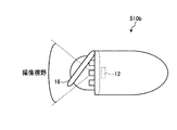
Next, a second modification of the present invention will be described. In
針16は、螺旋形状または略半輪形状の注射針であり、図46に示すようにカプセル本体511の光学ドーム部近傍に配置される。針16は、チューブ等を介してバルブ14と連通し、このバルブ14の開動作によって薬液タンク13と連通する。回転アクチュエータ513は、上述したモータ520と同様に制御基板17の制御回路によって駆動制御され、針16を回転させて突没する。この場合、回転アクチュエータ513は、撮像素子12の撮像視野内に針16を突出させる。なお、かかる回転アクチュエータ513は、図46に示すようにカプセル本体511の筐体外表面に配置されてもよいし、筐体内部に配置されてもよい。
The
シース512は、カプセル型内視鏡510bの筐体の一部分であり、図46に示すようにカプセル本体511に取り付けられ、このカプセル本体511の光学ドーム部以外を覆う。この場合、シース512は、突出前の針16および回転アクチュエータ513を内包する。なお、かかるシース512内の針16は、回転アクチュエータ513の駆動力によって回転しつつ、シース512から突没する。
The
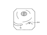
つぎに、この変形例2にかかるカプセル型内視鏡510bの針突没動作について説明する。図47は、この変形例2にかかるカプセル型内視鏡が撮像視野内に針を突出した状態を示す模式図である。図48は、この変形例2にかかるカプセル型内視鏡が撮像する画像の一例を示す模式図である。
Next, a needle projecting and retracting operation of the
被検体内部に導入されたカプセル型内視鏡510bは、被検体の臓器内部を移動しつつ、この被検体の臓器内部の画像である体内画像を順次撮像し、得られた体内画像を外部の受信部3(図1参照)に順次無線送信する。医師または看護師等のユーザは、かかるカプセル型内視鏡510bによって撮像された体内画像を表示部5(図1参照)に表示させて観察しつつ、このカプセル型内視鏡510bが被検体内部における患部等の所望部位に到達したか否かを判断する。
The
ここで、被検体内部のカプセル型内視鏡510bが体内における所望部位に到達した場合、図1に示した制御部4は、入力部6の入力情報に基づいて制御信号を生成し、この生成した制御信号をカプセル型内視鏡510bに無線送信するように受信部3を制御する。カプセル型内視鏡510bは、かかる制御部4からの制御信号に基づいて針16を突出させつつ、体内画像を撮像する。この場合、針16は、図47に示すように、シース512から突出して撮像素子12の撮像視野内に位置する。撮像素子12は、かかる撮像視野内の針16を含む体内画像を撮像する。かかる撮像素子12によって撮像された体内画像には、例えば図48に示すように、体内における所望部位の一例である患部514と突出状態の針16とが含まれる。ユーザは、かかる体内画像を参照することによって、針16と患部514との相対位置関係を容易に視認できる。ユーザは、かかる体内画像をもとに針16と患部514との相対位置関係を確認しつつ、カプセル型内視鏡510bの磁気誘導および針突出動作を操作する。かかるユーザ操作に基づいて、被検体内部のカプセル型内視鏡510bは、患部514近傍に針16を突出した上で磁気誘導され、これによって、確実に患部514に針16を突き刺すことができる。この結果、カプセル型内視鏡510bは、この患部514に薬液を確実に注射することができる。
Here, when the
このように、本発明の変形例2では、カプセル型内視鏡に内蔵した撮像素子の撮像視野内に注射針を突出して、被検体内部における患部等の所望部位と注射針との相対位置関係を捉えた体内画像を撮像するように構成した。このため、体内画像をもとに被検体内部の所望部位と注射針との相対位置関係を容易に視認でき、この体内画像を参照しつつカプセル型内視鏡の磁気誘導および針突出動作を操作することによって、この所望部位に容易に注射針を突き刺すことができる。この結果、体内部位に対する注射針の穿刺後に注射針を必要以上に突出させることなく、確実に所望部位に薬液を注射することができる。また、この所望部位に対する薬液の注射状況を体内画像によって視認できるため、所望部位からの薬液の漏出が発生した場合に即座に薬液放出を停止させることができる。 As described above, in the second modification of the present invention, the injection needle protrudes into the imaging field of the imaging element incorporated in the capsule endoscope, and the relative positional relationship between the desired site such as the affected part in the subject and the injection needle. The camera is configured to capture in-vivo images. Therefore, the relative positional relationship between the desired site inside the subject and the injection needle can be easily recognized based on the in-vivo image, and the magnetic guidance and needle protrusion operation of the capsule endoscope can be operated while referring to this in-vivo image. By doing so, the injection needle can be easily pierced into this desired site. As a result, the medicinal solution can be reliably injected into the desired site without causing the injection needle to protrude more than necessary after the injection needle has been punctured into the body site. Moreover, since the injection state of the chemical solution to the desired site can be visually confirmed by the in-vivo image, the release of the drug solution can be stopped immediately when the leakage of the drug solution from the desired site occurs.
なお、この変形例2にかかるカプセル型内視鏡510bに例示されるような針突出動作は、上述した実施の形態1〜5にかかるカプセル型内視鏡に適用することもできる。すなわち、実施の形態1〜5にかかるカプセル型内視鏡は、撮像素子の撮像視野内に注射針を突出し、この突出した注射針を被写体として含む体内画像を撮像してもよい。この場合も、上述した変形例2にかかるカプセル型内視鏡510bと同様の作用効果を享受することができる。
Note that the needle protrusion operation as exemplified in the
(変形例3)
つぎに、変形例3について説明する。実施の形態1〜5においては、電池19から供給される電力を用いてアクチュエータ15またはモータ520を動作させて針を突出させる場合について説明したが、変形例3においては、筐体内に設けられた二つの永久磁石間における反発力を利用して針を突出する場合について説明する(たとえば、本出願人による特願2007−46013がある。)。この場合、カプセル型内視鏡の筐体内に、磁化方向を含む平面内で相対的に回転可能に設置された第1の永久磁石および第2の永久磁石を設け、第1の永久磁石および第2の永久磁石が互いに反発力を発生する方向に第1の永久磁石および/または第2の永久磁石を相対的に回転させる磁界を与えればよい。(Modification 3)
Next,
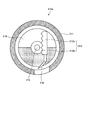
具体的に、図49および図50を参照して説明する。図49(1),(2)は、変形例3にかかるカプセル型内視鏡の軸方向の断面図であり、図49(3)は、図49(2)におけるEE線でカプセル型内視鏡を切断した断面図である。図50は、変形例3にかかるカプセル型内視鏡の所定の各状態において磁界発生部2が印加する磁界強度を示す図である。図49に示すように、変形例3にかかるカプセル型内視鏡510aにおいては、回転可能であり図49(2)の矢印Y51bの方向に移動可能である回転移動磁石518aと、回転可能である回転磁石518bとが相対するように設けられている。回転磁石518bが円滑に回転するように回転磁石518bの接触面上に摩擦低減部材509が設けられている。また、カプセル型内視鏡510aにおいては、回転磁石518b側の仕切りに回転移動磁石518aが接触した場合には、回転が拘束されるように、回転移動磁石518aの回転磁石518b側の表面上には、高摩擦部材508が設けられている。また、カプセル型内視鏡510aは、回転移動磁石518aの回転時に回転移動磁石518aに接続する歯車502aと噛み合って回転針516の回転動作を制御する歯車502bを有する。
Specifically, this will be described with reference to FIGS. 49 and 50. 49 (1) and 49 (2) are cross-sectional views in the axial direction of the capsule endoscope according to the modified example 3, and FIG. 49 (3) is a capsule endoscope along line EE in FIG. 49 (2). It is sectional drawing which cut | disconnected the mirror. FIG. 50 is a diagram showing the magnetic field strength applied by the
まず、図50の曲線l51dに示すように、磁界発生部2は、回転磁石518bよりも体積が大きい回転移動磁石518aが回転可能となる磁界強度G51よりも弱い磁界強度で、カプセル型内視鏡510aの長軸周りに回転磁界を印加する。この場合、図49(1)に示すように、回転移動磁石518aは、高摩擦部材508によって回転が拘束された状態となる。
First, as shown by a curve l51d in FIG. 50, the
薬液タンク13内の薬剤の局注時には、図50の曲線l54dに示すように、磁界発生部2は、回転移動磁石518aがカプセル型内視鏡510a内で回転可能となる磁界強度G51よりも強い磁界強度の磁界M51を印加する。この場合、図49(2)の矢印Y51aに示すように、回転移動磁石518aおよび回転磁石518bが磁界M51にしたがって同じ向きに回転し、反発力H51が発生する。そして、図49(2)の矢印Y51bに示すように、回転移動磁石518aは、この反発力H51によって回転磁石518bから離れるように左方向に移動し、回転移動磁石518aに設けられた歯車502aは歯車502bと噛み合う。また、回転移動磁石518aにおいては、高摩擦部材508による回転の拘束が解除され、回転可能となる。そして、カプセル型内視鏡510aは、磁界強度G51よりも強い磁界強度で回転針516の回転方向に対応した向きの磁界が印加されることによって回転し、これにともない歯車502a,502bもそれぞれ回転する。この結果、図49(3)に示すように、歯車502bの回転によって、回転針516が矢印Y51cに示すように回転し、カプセル型内視鏡510a外に突出する。そして、回転針516が回転停止面に接触すると、カプセル型内視鏡510a本体が回転し、腸管などの周方向に沿って回転針516が穿刺される。さらに、薬液タンク13の貫通穴533と回転針516の図示しない貫通穴が接続するため、薬液タンク13内の薬剤が回転針516を介して所望の領域に注入されることとなる。
At the time of local injection of the drug in the
そして、磁界強度G51よりも強い磁界強度のまま磁界の向きを逆転させることによって、回転針516がカプセル型内視鏡510a内に収納され、さらに、印加された磁界の磁界強度G51よりも弱めることによって、回転移動磁石518aが図49(1)に示すようにカプセル型内視鏡510aに固定されることとなる。このように、筐体内に設けられた二つの永久磁石間における反発力を利用して円滑に針16を突出してもよい。
Then, by reversing the direction of the magnetic field while maintaining a magnetic field strength stronger than the magnetic field strength G51, the
なお、これまで被検体内導入装置として光学的観察を行なうカプセル型内視鏡について説明してきたが、光学的観察に限らず、超音波断層観察やpH計測等を行なうカプセル型医療装置でも構わない。また、カプセル型筐体に細長挿入部を取り付けたひも付きカプセル型医療装置にも適用可能である。 Note that the capsule endoscope that performs optical observation has been described as the intra-subject introduction apparatus so far, but is not limited to optical observation, and may be a capsule medical apparatus that performs ultrasonic tomographic observation, pH measurement, or the like. . Further, the present invention is also applicable to a capsule-type medical device with a string in which an elongated insertion portion is attached to a capsule-type housing.
以上のように、本発明にかかる被検体内導入システムは、被検体内部に導入した被検体内導入装置による体内部位への薬液注射に有用であり、特に、体内部位の穿刺対象層に注射針を確実に刺すことができる被検体内導入システムに適している。 As described above, the in-subject introduction system according to the present invention is useful for injecting a chemical solution into a body part by the in-subject introduction apparatus introduced into the subject, and in particular, an injection needle on the puncture target layer in the body part. This is suitable for an in-subject introduction system that can reliably puncture the body.
Claims (20)
前記被検体内導入装置は、
前記被検体内導入装置を構成する筐体内に設けられ、磁化方向を有する磁気応答部と、
前記筐体の表面に対して突出および収納が可能である針と、
を備え、
前記制御装置は、
前記被検体内に磁界を発生する磁界発生部と、
前記被検体内導入装置の位置及び姿勢を検出する位置姿勢検出部と、
前記位置姿勢検出部によって検出された前記被検体内導入装置における磁気応答部の磁化方向、前記被検体内導入装置における針の位置、および前記針の先端方向をもとに、前記磁気応答部の方向を変化させる磁界を前記磁界発生部に発生させて、突出した前記針が穿刺対象層に穿刺できるように前記被検体内導入装置全体の方向を変化させる制御部と、を備え、
前記制御部は、前記被検体内導入装置に対してまず針を穿刺する直前の第1の姿勢となるように前記磁界発生部から第1の磁界を発生させると共に前記針を突出させ、続いて前記被検体内導入装置全体の方向を前記第1の姿勢から変化させて前記針を穿刺対象層に穿刺させるべく第2の磁界を発生させることを特徴とする被検体内導入システム。 In an intra-subject introduction system comprising an intra-subject introduction device introduced into the subject and a control device that controls the operation of the intra-subject introduction device.
The in-subject introduction device comprises:
A magnetic response unit provided in a casing constituting the in-subject introduction apparatus and having a magnetization direction;
A needle that can project and house with respect to the surface of the housing;
With
The control device includes:
A magnetic field generator for generating a magnetic field in the subject;
A position and orientation detection unit for detecting the position and orientation of the in-subject introduction apparatus;
Based on the magnetization direction of the magnetic response unit in the in-subject introduction device detected by the position and orientation detection unit, the position of the needle in the in-subject introduction device, and the tip direction of the needle, A control unit that generates a magnetic field that changes a direction in the magnetic field generation unit and changes a direction of the entire in-subject introduction device so that the protruding needle can puncture the puncture target layer, and
The control unit generates a first magnetic field from the magnetic field generation unit so as to be in a first posture immediately before puncturing the needle with respect to the in-subject introduction apparatus, and then causes the needle to protrude, An in-subject introduction system, wherein a direction of the whole in-subject introduction apparatus is changed from the first posture to generate a second magnetic field to puncture the puncture target layer .
L+21/2(r/2)≧(r2/2+2r+1)1/2
の関係を有することを特徴とする請求項11に記載の被検体内導入システム。 The length (L) when the needle protrudes is between the outer diameter (2r) of the housing,
L + 2 1/2 (r / 2 ) ≧ (r 2/2 + 2r + 1) 1/2
The intra-subject introduction system according to claim 11, characterized in that:
前記針は、前記筐体から突出した場合、前記画像取得部の視野内に位置することを特徴とする請求項1に記載の被検体内導入システム。 The in-subject introduction apparatus includes an image acquisition unit that acquires an in-vivo image of the subject,
The in-subject introduction system according to claim 1, wherein the needle is positioned in a visual field of the image acquisition unit when protruding from the housing.
Priority Applications (1)
| Application Number | Priority Date | Filing Date | Title |
|---|---|---|---|
| JP2009534375A JP5399253B2 (en) | 2007-09-26 | 2008-09-25 | Intra-subject introduction system |
Applications Claiming Priority (4)
| Application Number | Priority Date | Filing Date | Title |
|---|---|---|---|
| JP2007249970 | 2007-09-26 | ||
| JP2007249970 | 2007-09-26 | ||
| PCT/JP2008/067331 WO2009041525A1 (en) | 2007-09-26 | 2008-09-25 | Introduction-into-subject system |
| JP2009534375A JP5399253B2 (en) | 2007-09-26 | 2008-09-25 | Intra-subject introduction system |
Publications (2)
| Publication Number | Publication Date |
|---|---|
| JPWO2009041525A1 JPWO2009041525A1 (en) | 2011-01-27 |
| JP5399253B2 true JP5399253B2 (en) | 2014-01-29 |
Family
ID=40511407
Family Applications (1)
| Application Number | Title | Priority Date | Filing Date |
|---|---|---|---|
| JP2009534375A Active JP5399253B2 (en) | 2007-09-26 | 2008-09-25 | Intra-subject introduction system |
Country Status (5)
| Country | Link |
|---|---|
| US (1) | US8529433B2 (en) |
| EP (1) | EP2196131A4 (en) |
| JP (1) | JP5399253B2 (en) |
| CN (1) | CN101808567B (en) |
| WO (1) | WO2009041525A1 (en) |
Cited By (1)
| Publication number | Priority date | Publication date | Assignee | Title |
|---|---|---|---|---|
| WO2019022340A1 (en) * | 2017-07-25 | 2019-01-31 | 한양대학교 산학협력단 | Magnetic robot |
Families Citing this family (51)
| Publication number | Priority date | Publication date | Assignee | Title |
|---|---|---|---|---|
| EP2063785A4 (en) | 2006-09-06 | 2011-08-31 | Innurvation Inc | System and method for acoustic information exchange involving an ingestible low power capsule |
| JP5269348B2 (en) * | 2007-05-21 | 2013-08-21 | オリンパス株式会社 | Position detection system and method of operating the position detection system |
| US9521961B2 (en) | 2007-11-26 | 2016-12-20 | C. R. Bard, Inc. | Systems and methods for guiding a medical instrument |
| JP5452500B2 (en) | 2007-11-26 | 2014-03-26 | シー・アール・バード・インコーポレーテッド | Integrated system for intravascular placement of catheters |
| US8781555B2 (en) | 2007-11-26 | 2014-07-15 | C. R. Bard, Inc. | System for placement of a catheter including a signal-generating stylet |
| US9456766B2 (en) | 2007-11-26 | 2016-10-04 | C. R. Bard, Inc. | Apparatus for use with needle insertion guidance system |
| JP5314913B2 (en) * | 2008-04-03 | 2013-10-16 | オリンパスメディカルシステムズ株式会社 | Capsule medical system |
| WO2010005571A2 (en) | 2008-07-09 | 2010-01-14 | Innurvation, Inc. | Displaying image data from a scanner capsule |
| CN102196763B (en) | 2009-01-28 | 2013-08-14 | 奥林巴斯医疗株式会社 | Capsule medical device system |
| US9532724B2 (en) | 2009-06-12 | 2017-01-03 | Bard Access Systems, Inc. | Apparatus and method for catheter navigation using endovascular energy mapping |
| ITFI20090150A1 (en) * | 2009-07-08 | 2011-01-09 | Korea Inst Sci & Tech | IMPLEMENTATION DEVICE FOR ENDOSCOPIC CAPS |
| EP3466438A1 (en) | 2009-08-03 | 2019-04-10 | Incube Labs, Llc | Swallowable capsule and method for stimulating incretin production within the intestinal tract |
| US9179827B2 (en) * | 2009-12-15 | 2015-11-10 | Boston Scientific Scimed, Inc. | Systems and methods for determining the position and orientation of medical devices inserted into a patient |
| US8562589B2 (en) | 2009-12-24 | 2013-10-22 | Rani Therapeutics, Llc | Swallowable drug delivery device and method of delivery |
| WO2011112229A2 (en) * | 2010-03-10 | 2011-09-15 | Incube Labs, Llc | Therapeutic agent preparations for delivery into a lumen of the intestinal tract using a swallowable drug delivery device |
| EP2515992B1 (en) * | 2009-12-24 | 2018-10-10 | Rani Therapeutics, LLC | Swallowable drug delivery device |
| US8647259B2 (en) * | 2010-03-26 | 2014-02-11 | Innurvation, Inc. | Ultrasound scanning capsule endoscope (USCE) |
| EP2624779B1 (en) * | 2010-10-08 | 2018-05-30 | Koninklijke Philips N.V. | Endoscopy-guided deployment of vessel punch |
| US8846040B2 (en) | 2010-12-23 | 2014-09-30 | Rani Therapeutics, Llc | Therapeutic agent preparations comprising etanercept for delivery into a lumen of the intestinal tract using a swallowable drug delivery device |
| US8809269B2 (en) | 2010-12-23 | 2014-08-19 | Rani Therapeutics, Llc | Therapeutic agent preparations comprising insulin for delivery into a lumen of the intestinal tract using a swallowable drug delivery device |
| US9402806B2 (en) | 2010-12-23 | 2016-08-02 | Rani Therapeutics, Llc | Therapeutic agent preparations for delivery into a lumen of the intestinal tract using a swallowable drug delivery device |
| US9149617B2 (en) | 2010-12-23 | 2015-10-06 | Rani Therapeutics, Llc | Device, system and methods for the oral delivery of therapeutic compounds |
| US8809271B2 (en) | 2010-12-23 | 2014-08-19 | Rani Therapeutics, Llc | Therapeutic agent preparations comprising liraglutide for delivery into a lumen of the intestinal tract using a swallowable drug delivery device |
| US9402807B2 (en) | 2010-12-23 | 2016-08-02 | Rani Therapeutics, Llc | Therapeutic agent preparations for delivery into a lumen of the intestinal tract using a swallowable drug delivery device |
| US10639272B2 (en) | 2010-12-23 | 2020-05-05 | Rani Therapeutics, Llc | Methods for delivering etanercept preparations into a lumen of the intestinal tract using a swallowable drug delivery device |
| US9629799B2 (en) | 2010-12-23 | 2017-04-25 | Rani Therapeutics, Llc | Therapeutic agent preparations for delivery into a lumen of the intestinal tract using a swallowable drug delivery device |
| US8734429B2 (en) | 2010-12-23 | 2014-05-27 | Rani Therapeutics, Llc | Device, system and methods for the oral delivery of therapeutic compounds |
| US8764733B2 (en) | 2010-12-23 | 2014-07-01 | Rani Therapeutics, Llc | Therapeutic agent preparations for delivery into a lumen of the intestinal tract using a swallowable drug delivery device |
| US9283179B2 (en) | 2010-12-23 | 2016-03-15 | Rani Therapeutics, Llc | GnRH preparations for delivery into a lumen of the intestinal tract using a swallowable drug delivery device |
| US9259386B2 (en) | 2010-12-23 | 2016-02-16 | Rani Therapeutics, Llc | Therapeutic preparation comprising somatostatin or somatostatin analogoue for delivery into a lumen of the intestinal tract using a swallowable drug delivery device |
| US8969293B2 (en) | 2010-12-23 | 2015-03-03 | Rani Therapeutics, Llc | Therapeutic agent preparations comprising exenatide for delivery into a lumen of the intestinal tract using a swallowable drug delivery device |
| US9415004B2 (en) | 2010-12-23 | 2016-08-16 | Rani Therapeutics, Llc | Therapeutic agent preparations for delivery into a lumen of the intestinal tract using a swallowable drug delivery device |
| US9861683B2 (en) | 2010-12-23 | 2018-01-09 | Rani Therapeutics, Llc | Therapeutic agent preparations for delivery into a lumen of the intestinal tract using a swallowable drug delivery device |
| US8980822B2 (en) | 2010-12-23 | 2015-03-17 | Rani Therapeutics, Llc | Therapeutic agent preparations comprising pramlintide for delivery into a lumen of the intestinal tract using a swallowable drug delivery device |
| US9284367B2 (en) | 2010-12-23 | 2016-03-15 | Rani Therapeutics, Llc | Therapeutic agent preparations for delivery into a lumen of the intestinal tract using a swallowable drug delivery device |
| KR101256408B1 (en) | 2011-08-25 | 2013-04-25 | 전남대학교산학협력단 | A Micro-Robot System And Capsule Endoscope System For Diagnosing Of Tubular Digestive Organ |
| JP6265630B2 (en) * | 2013-06-13 | 2018-01-24 | オリンパス株式会社 | Endoscope apparatus and method for operating endoscope apparatus |
| JP6521707B2 (en) | 2014-07-10 | 2019-05-29 | キヤノン株式会社 | Puncture planning device and puncture system |
| CN106922121B (en) * | 2014-11-20 | 2019-03-01 | 奥林巴斯株式会社 | Capsule endoscope system, capsule endoscope, the wireless communications method of capsule endoscope and program |
| WO2016210325A1 (en) | 2015-06-26 | 2016-12-29 | C.R. Bard, Inc. | Connector interface for ecg-based catheter positioning system |
| WO2018213588A1 (en) | 2017-05-17 | 2018-11-22 | Massachusetts Institute Of Technology | Tissue anchoring articles |
| US11541015B2 (en) | 2017-05-17 | 2023-01-03 | Massachusetts Institute Of Technology | Self-righting systems, methods, and related components |
| WO2018219741A1 (en) * | 2017-05-29 | 2018-12-06 | MAX-PLANCK-Gesellschaft zur Förderung der Wissenschaften e.V. | Magnetically actuated capsule endoscope, magnetic field generating and sensing apparatus and method of actuating a magnetically actuated capsule endoscope |
| KR101979772B1 (en) * | 2017-07-12 | 2019-05-17 | 전남대학교산학협력단 | A capsule endoscope having a front tattooing |
| CN108095806B (en) * | 2017-12-16 | 2023-04-28 | 重庆金山科技(集团)有限公司 | Adsorption puncture fixing device with self-locking function |
| WO2019222570A1 (en) | 2018-05-17 | 2019-11-21 | Massachusetts Institute Of Technology | Systems for electrical stimulation |
| US20210275269A1 (en) * | 2018-07-12 | 2021-09-09 | Bionaut Labs Ltd. | Magnetic propulsion mechanism for magnetic devices |
| EP3852622A1 (en) | 2018-10-16 | 2021-07-28 | Bard Access Systems, Inc. | Safety-equipped connection systems and methods thereof for establishing electrical connections |
| JP2022523121A (en) | 2019-02-01 | 2022-04-21 | マサチューセッツ インスティテュート オブ テクノロジー | Systems and methods for liquid injection |
| US11541216B2 (en) | 2019-11-21 | 2023-01-03 | Massachusetts Institute Of Technology | Methods for manufacturing tissue interfacing components |
| WO2023022966A1 (en) * | 2021-08-16 | 2023-02-23 | Bionaut Labs Ltd. | Tether-free robotic system to perform a remote microsurgery in the central nervous system (cns) |
Citations (4)
| Publication number | Priority date | Publication date | Assignee | Title |
|---|---|---|---|---|
| JP2003275170A (en) * | 2002-03-25 | 2003-09-30 | Olympus Optical Co Ltd | Encapsulated medical device |
| JP2003325438A (en) * | 2002-05-10 | 2003-11-18 | Olympus Optical Co Ltd | Capsule type medical treatment device |
| JP2005124708A (en) * | 2003-10-22 | 2005-05-19 | Olympus Corp | Body inside observing device |
| JP2007151729A (en) * | 2005-12-02 | 2007-06-21 | Olympus Medical Systems Corp | Capsule type medical device, its guidance system and guidance method |
Family Cites Families (18)
| Publication number | Priority date | Publication date | Assignee | Title |
|---|---|---|---|---|
| JPH06114036A (en) * | 1992-10-05 | 1994-04-26 | Olympus Optical Co Ltd | Capsule for medical treatment |
| JP2002000556A (en) * | 2000-06-26 | 2002-01-08 | Nonomura Tomosuke | Endoscope |
| US7946979B2 (en) * | 2002-12-26 | 2011-05-24 | Given Imaging, Ltd. | Immobilizable in vivo sensing device |
| JP2004222998A (en) | 2003-01-23 | 2004-08-12 | Olympus Corp | Ultrasonic diagnostic capsule |
| JP4503930B2 (en) * | 2003-01-30 | 2010-07-14 | オリンパス株式会社 | Medical equipment |
| JP4309684B2 (en) | 2003-03-14 | 2009-08-05 | オリンパス株式会社 | Capsule ultrasound endoscope |
| US20040199054A1 (en) * | 2003-04-03 | 2004-10-07 | Wakefield Glenn Mark | Magnetically propelled capsule endoscopy |
| JP4436631B2 (en) * | 2003-08-04 | 2010-03-24 | オリンパス株式会社 | Capsule endoscope |
| US7623904B2 (en) * | 2003-08-06 | 2009-11-24 | Olympus Corporation | Medical apparatus, medical apparatus guide system, capsule type medical apparatus, and capsule type medical apparatus guide apparatus |
| US20050124875A1 (en) | 2003-10-01 | 2005-06-09 | Olympus Corporation | Vivo observation device |
| JP4589048B2 (en) * | 2004-08-04 | 2010-12-01 | オリンパス株式会社 | Capsule endoscope |
| US20090018396A1 (en) * | 2005-07-08 | 2009-01-15 | Hironobu Takizawa | Indwelling device for encapsulated medical device, in-vivo indwelling device for capsule endoscope, and capsule-indwelling medical device |
| EP1932462A4 (en) | 2005-10-05 | 2013-02-27 | Olympus Medical Systems Corp | Capsule type medical device, its guidance system and guidance method and examinee insertion device |
| JP4358821B2 (en) * | 2005-12-15 | 2009-11-04 | オリンパス株式会社 | Intra-subject introduction device |
| EP2335559A1 (en) * | 2005-12-27 | 2011-06-22 | Olympus Medical Systems Corporation | Encapsulated medical device guidance system |
| CN101351147B (en) * | 2005-12-28 | 2010-12-15 | 奥林巴斯医疗株式会社 | Body-insertable device system and body-insertable device guiding method |
| JP4757021B2 (en) * | 2005-12-28 | 2011-08-24 | オリンパス株式会社 | Position detection system |
| JP5006381B2 (en) * | 2007-02-26 | 2012-08-22 | オリンパスメディカルシステムズ株式会社 | Magnetic actuator, operating method of magnetic actuator, and capsule endoscope using the same |
-
2008
- 2008-09-25 JP JP2009534375A patent/JP5399253B2/en active Active
- 2008-09-25 EP EP08833792A patent/EP2196131A4/en not_active Withdrawn
- 2008-09-25 WO PCT/JP2008/067331 patent/WO2009041525A1/en active Application Filing
- 2008-09-25 CN CN2008801085512A patent/CN101808567B/en not_active Expired - Fee Related
-
2010
- 2010-03-24 US US12/730,325 patent/US8529433B2/en active Active
Patent Citations (4)
| Publication number | Priority date | Publication date | Assignee | Title |
|---|---|---|---|---|
| JP2003275170A (en) * | 2002-03-25 | 2003-09-30 | Olympus Optical Co Ltd | Encapsulated medical device |
| JP2003325438A (en) * | 2002-05-10 | 2003-11-18 | Olympus Optical Co Ltd | Capsule type medical treatment device |
| JP2005124708A (en) * | 2003-10-22 | 2005-05-19 | Olympus Corp | Body inside observing device |
| JP2007151729A (en) * | 2005-12-02 | 2007-06-21 | Olympus Medical Systems Corp | Capsule type medical device, its guidance system and guidance method |
Cited By (2)
| Publication number | Priority date | Publication date | Assignee | Title |
|---|---|---|---|---|
| WO2019022340A1 (en) * | 2017-07-25 | 2019-01-31 | 한양대학교 산학협력단 | Magnetic robot |
| US11642108B2 (en) | 2017-07-25 | 2023-05-09 | Industry-University Cooperation Foundation, Hanyong University | Magnetic robot |
Also Published As
| Publication number | Publication date |
|---|---|
| JPWO2009041525A1 (en) | 2011-01-27 |
| CN101808567A (en) | 2010-08-18 |
| WO2009041525A1 (en) | 2009-04-02 |
| EP2196131A1 (en) | 2010-06-16 |
| EP2196131A4 (en) | 2012-12-05 |
| US20100179381A1 (en) | 2010-07-15 |
| CN101808567B (en) | 2012-09-05 |
| US8529433B2 (en) | 2013-09-10 |
Similar Documents
| Publication | Publication Date | Title |
|---|---|---|
| JP5399253B2 (en) | Intra-subject introduction system | |
| JP4642941B2 (en) | Capsule medical device | |
| JP4137740B2 (en) | Capsule type medical device and capsule type medical device guidance system | |
| JP5314913B2 (en) | Capsule medical system | |
| US8740774B2 (en) | Capsule-type medical apparatus, guidance system and guidance method therefor, and intrasubject insertion apparatus | |
| JP4578740B2 (en) | Capsule medical device | |
| US20070173691A1 (en) | Capsule-type medical device | |
| EP2189100B1 (en) | Medical apparatus | |
| Ciuti et al. | Capsule endoscopy: from current achievements to open challenges | |
| JP4503930B2 (en) | Medical equipment | |
| US6958034B2 (en) | Self propelled device | |
| JP5100336B2 (en) | Capsule medical device | |
| JP4081259B2 (en) | Endoscope apparatus and endoscope detachment method | |
| JP4827540B2 (en) | In-subject insertion device | |
| JP5203050B2 (en) | Capsule medical device | |
| JP4129269B2 (en) | Capsule medical device | |
| JP4642424B2 (en) | In-body medical device | |
| JP2006325874A (en) | Capsule ultrasonic endoscope and capsule ultrasonic endoscope system | |
| Hoang et al. | Intestinal tattooing mechanism integrated with active wireless capsule endoscope | |
| JP2015089402A (en) | Endoscope apparatus | |
| JP4681855B2 (en) | Ultrasound diagnostic medical capsule |
Legal Events
| Date | Code | Title | Description |
|---|---|---|---|
| A621 | Written request for application examination |
Free format text: JAPANESE INTERMEDIATE CODE: A621 Effective date: 20110323 |
|
| A131 | Notification of reasons for refusal |
Free format text: JAPANESE INTERMEDIATE CODE: A131 Effective date: 20130611 |
|
| A521 | Request for written amendment filed |
Free format text: JAPANESE INTERMEDIATE CODE: A523 Effective date: 20130802 |
|
| TRDD | Decision of grant or rejection written | ||
| A01 | Written decision to grant a patent or to grant a registration (utility model) |
Free format text: JAPANESE INTERMEDIATE CODE: A01 Effective date: 20131008 |
|
| A61 | First payment of annual fees (during grant procedure) |
Free format text: JAPANESE INTERMEDIATE CODE: A61 Effective date: 20131023 |
|
| R151 | Written notification of patent or utility model registration |
Ref document number: 5399253 Country of ref document: JP Free format text: JAPANESE INTERMEDIATE CODE: R151 |
|
| S111 | Request for change of ownership or part of ownership |
Free format text: JAPANESE INTERMEDIATE CODE: R313111 |
|
| R350 | Written notification of registration of transfer |
Free format text: JAPANESE INTERMEDIATE CODE: R350 |
|
| S531 | Written request for registration of change of domicile |
Free format text: JAPANESE INTERMEDIATE CODE: R313531 |
|
| R350 | Written notification of registration of transfer |
Free format text: JAPANESE INTERMEDIATE CODE: R350 |
|
| R250 | Receipt of annual fees |
Free format text: JAPANESE INTERMEDIATE CODE: R250 |
|
| R250 | Receipt of annual fees |
Free format text: JAPANESE INTERMEDIATE CODE: R250 |
|
| R250 | Receipt of annual fees |
Free format text: JAPANESE INTERMEDIATE CODE: R250 |
|
| R250 | Receipt of annual fees |
Free format text: JAPANESE INTERMEDIATE CODE: R250 |
|
| R250 | Receipt of annual fees |
Free format text: JAPANESE INTERMEDIATE CODE: R250 |
|
| R250 | Receipt of annual fees |
Free format text: JAPANESE INTERMEDIATE CODE: R250 |