JP5308668B2 - Liquid dispensing device - Google Patents
Liquid dispensing device Download PDFInfo
- Publication number
- JP5308668B2 JP5308668B2 JP2007526610A JP2007526610A JP5308668B2 JP 5308668 B2 JP5308668 B2 JP 5308668B2 JP 2007526610 A JP2007526610 A JP 2007526610A JP 2007526610 A JP2007526610 A JP 2007526610A JP 5308668 B2 JP5308668 B2 JP 5308668B2
- Authority
- JP
- Japan
- Prior art keywords
- liquid
- dispensing
- button
- pump
- hole
- Prior art date
- Legal status (The legal status is an assumption and is not a legal conclusion. Google has not performed a legal analysis and makes no representation as to the accuracy of the status listed.)
- Active
Links
Images


Classifications
-
- B—PERFORMING OPERATIONS; TRANSPORTING
- B65—CONVEYING; PACKING; STORING; HANDLING THIN OR FILAMENTARY MATERIAL
- B65D—CONTAINERS FOR STORAGE OR TRANSPORT OF ARTICLES OR MATERIALS, e.g. BAGS, BARRELS, BOTTLES, BOXES, CANS, CARTONS, CRATES, DRUMS, JARS, TANKS, HOPPERS, FORWARDING CONTAINERS; ACCESSORIES, CLOSURES, OR FITTINGS THEREFOR; PACKAGING ELEMENTS; PACKAGES
- B65D83/00—Containers or packages with special means for dispensing contents
- B65D83/14—Containers or packages with special means for dispensing contents for delivery of liquid or semi-liquid contents by internal gaseous pressure, i.e. aerosol containers comprising propellant for a product delivered by a propellant
- B65D83/16—Containers or packages with special means for dispensing contents for delivery of liquid or semi-liquid contents by internal gaseous pressure, i.e. aerosol containers comprising propellant for a product delivered by a propellant characterised by the actuating means
- B65D83/20—Containers or packages with special means for dispensing contents for delivery of liquid or semi-liquid contents by internal gaseous pressure, i.e. aerosol containers comprising propellant for a product delivered by a propellant characterised by the actuating means operated by manual action, e.g. button-type actuator or actuator caps
- B65D83/205—Actuator caps, or peripheral actuator skirts, attachable to the aerosol container
-
- A—HUMAN NECESSITIES
- A44—HABERDASHERY; JEWELLERY
- A44B—BUTTONS, PINS, BUCKLES, SLIDE FASTENERS, OR THE LIKE
- A44B15/00—Key-rings
- A44B15/005—Fobs
-
- B—PERFORMING OPERATIONS; TRANSPORTING
- B05—SPRAYING OR ATOMISING IN GENERAL; APPLYING FLUENT MATERIALS TO SURFACES, IN GENERAL
- B05B—SPRAYING APPARATUS; ATOMISING APPARATUS; NOZZLES
- B05B11/00—Single-unit hand-held apparatus in which flow of contents is produced by the muscular force of the operator at the moment of use
- B05B11/0005—Components or details
- B05B11/0037—Containers
- B05B11/0038—Inner container disposed in an outer shell or outer casing
-
- B—PERFORMING OPERATIONS; TRANSPORTING
- B05—SPRAYING OR ATOMISING IN GENERAL; APPLYING FLUENT MATERIALS TO SURFACES, IN GENERAL
- B05B—SPRAYING APPARATUS; ATOMISING APPARATUS; NOZZLES
- B05B11/00—Single-unit hand-held apparatus in which flow of contents is produced by the muscular force of the operator at the moment of use
- B05B11/01—Single-unit hand-held apparatus in which flow of contents is produced by the muscular force of the operator at the moment of use characterised by the means producing the flow
- B05B11/10—Pump arrangements for transferring the contents from the container to a pump chamber by a sucking effect and forcing the contents out through the dispensing nozzle
- B05B11/1042—Components or details
- B05B11/1052—Actuation means
-
- A—HUMAN NECESSITIES
- A45—HAND OR TRAVELLING ARTICLES
- A45D—HAIRDRESSING OR SHAVING EQUIPMENT; EQUIPMENT FOR COSMETICS OR COSMETIC TREATMENTS, e.g. FOR MANICURING OR PEDICURING
- A45D2200/00—Details not otherwise provided for in A45D
- A45D2200/05—Details of containers
- A45D2200/054—Means for supplying liquid to the outlet of the container
- A45D2200/057—Spray nozzles; Generating atomised liquid
-
- B—PERFORMING OPERATIONS; TRANSPORTING
- B05—SPRAYING OR ATOMISING IN GENERAL; APPLYING FLUENT MATERIALS TO SURFACES, IN GENERAL
- B05B—SPRAYING APPARATUS; ATOMISING APPARATUS; NOZZLES
- B05B11/00—Single-unit hand-held apparatus in which flow of contents is produced by the muscular force of the operator at the moment of use
- B05B11/0005—Components or details
- B05B11/0037—Containers
Landscapes
- Chemical & Material Sciences (AREA)
- Dispersion Chemistry (AREA)
- Engineering & Computer Science (AREA)
- Mechanical Engineering (AREA)
- Containers And Packaging Bodies Having A Special Means To Remove Contents (AREA)
- Sampling And Sample Adjustment (AREA)
- Closures For Containers (AREA)
- Supports Or Holders For Household Use (AREA)
- Feeding, Discharge, Calcimining, Fusing, And Gas-Generation Devices (AREA)
Abstract
Description
本発明は、携帯型液体分配装置に関する。さらに、本発明は、使用しないときに隠れており、経口ケア製品のような液体を噴霧しようとするときには露出する収容式ノズルを備える分配装置に関する。この液体分配装置は、随意に、キー・ホルダを備えていてもよい。 The present invention relates to a portable liquid dispensing apparatus. Furthermore, the present invention relates to a dispensing device comprising a retractable nozzle that is hidden when not in use and is exposed when a liquid such as an oral care product is to be sprayed. The liquid dispensing device may optionally include a key holder.
携帯型液体分配装置は、消費者にとって望ましい製品である。この装置は、限定するものではないが、口臭消し剤のような経口ケア製品、忌避剤(たとえば、催涙ガス、トウガラシスプレー)、日焼止めローション、解氷剤などの個人用製品を含む種々の噴霧可能な液体を計量分配するのに使用できる。このような装置は、ポケット、財布などに入れて携行できる。 Portable liquid dispensing devices are a desirable product for consumers. This device includes a variety of personal products such as, but not limited to, oral care products such as bad breath deodorants, repellents (eg, tear gas, pepper spray), sunscreen lotions, deicers, etc. Can be used to dispense sprayable liquids. Such a device can be carried in a pocket, wallet or the like.
携帯型液体分配装置は、それがポケットまたは財布内にある間などに液体が早まってまたは偶発的に分配されてしまうと具合が悪いことになる。この問題に対処する1つの方法は、装置のノズル用の錠止機構を設けることである。この錠止機構は、錠止時に、ポンプ組立体(ノズルから液体を放出するのに使用される)との偶発的な接触を防止する。このような方式は望ましくない液体の放出を防ぐことはできるが、消費者にとって錠止機構を操作するのが難しかったり、液体分配装置を使用しないときに錠止装置を掛けるのを忘れたりすることがある。 A portable liquid dispensing device can be uncomfortable if the liquid is dispensed prematurely or accidentally, such as while it is in a pocket or purse. One way to deal with this problem is to provide a locking mechanism for the nozzle of the device. This locking mechanism prevents accidental contact with the pump assembly (used to discharge liquid from the nozzle) during locking. Such a system can prevent unwanted liquid release, but it is difficult for consumers to operate the locking mechanism or forget to lock when not using the liquid dispensing device. There is.
したがって、口臭消し剤のような経口ケア製品、忌避剤(たとえば、催涙ガス、トウガラシスプレー)、日焼止め、解氷剤のような個人用製品などの液体を選択的に噴霧する組立体を備え、偶発的な液体の噴霧を防ぐための容易に掛止可能な機構を備える液体分配装置があれば望ましいであろう。このような装置は、消費者に対する利便性を高めるであろうし、口臭消し剤のような液体製品を、欠陥や偶発的な液体放出なしに容易かつ便利に使用するのを可能にするであろう。 Therefore, it is equipped with an assembly that selectively sprays liquids such as oral care products such as bad breath deodorants, repellents (eg tear gas, pepper sprays), personal products such as sunscreens and deicers It would be desirable to have a liquid dispensing device with an easily latchable mechanism to prevent accidental liquid spraying. Such a device would increase the convenience for the consumer and would allow liquid products such as bad breath removers to be used easily and conveniently without defects or accidental liquid discharge. .
液体分配装置から液体を分配するときに使用者が完全に制御できるように、偶発的な放出から保護した分配組立体を備えた液体分配装置を提供することはさらなる進歩であろう。 It would be a further advancement to provide a liquid dispensing device with a dispensing assembly that is protected from accidental release so that the user has full control when dispensing the liquid from the liquid dispensing device.
また、キーその他の携帯品を保持するための組立体を備えた液体分配装置があれば望ましいであろう。このような装置は、消費者に対する利便性を高めることになろう。 It would also be desirable to have a liquid dispensing device with an assembly for holding keys and other portable items. Such a device would increase convenience for consumers.
添付の図面(ただし、図1から図5Bを除く)は、本発明の実施形態を例示しているものであり、本願の一部をなす特許請求の範囲に包含されそしてそれにより定義されている発明を限定することを意図するものではない。
図1は、液体分配組立体が噴霧可能な液体を給送する使用位置にある、シールドを使用する、液体分配装置の一実施態様の正面図である。
図2は、液体分配組立体が噴霧可能な液体が放出されるのを防ぐ保管(たとえば、非作動)位置にある、オプションのキー・ホルダを備えた、図1に示す実施態様の正面図である。
図3は、図1、2に示す液体分配装置の実施態様の展開図である。
図4は、噴霧可能な液体の放出を防ぐ位置にあるシールドの側面図である。
図5Aは、動作可能なようにシールドと係合するトラックの頂平面図である。
図5Bは、図5Aに示すトラックと動作可能なように係合するランナーを示すシールドの底面図である。
図6Aは、オプションのキー・ホルダを備えた液体分配装置の一例示実施態様の正面図
である。
図6Bは、液体分配組立体が作動位置にあり、保護シールドが噴霧可能な液体の分配を可能にする位置にある、図6Aに示した実施態様の正面図である。
図7は、図6A、6Bに示した実施態様の展開図である。
図8A〜8Cは、液体を分配するためのアクチュエータ組立体の動作を示す、図6A〜7の装置の断面図である。
図9は、一例示実施態様によるディスペンサ装置の斜視図である。
図9Aは、図9に示すディスペンサ装置の展開斜視図である。
図10は、一例示実施態様によるディスペンサ装置のカバーの正面立面図である。
図10Aは、図10に示すカバーの頂平面図である。
図10Bは、図10に示すB−B線に沿ったカバーの断面図である。
図10Cは、図10Aに示すA−A線に沿ったカバーの断面図である。
図11は、一例示実施態様によるディスペンサ装置のボタンの正面斜視図である。
図11Aは、図11に示すボタンの頂平面図である。
図11Bは、図11Aに示すA−A線に沿ったボタンの断面図である。
図11Cは、図11Aに示すB−B線に沿ったボタンの断面図である。
図12は、一例示実施態様によるディスペンサ装置のカラーの正面斜視図である。
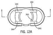
図12Aは、図12に示すカラーの頂平面図である。
図12Bは、図12Aに示すA−A線に沿ったカラーの断面図である。
図13は、第1の位置、すなわち、保管位置を示している、図9に示す装置の中心線に沿った分配装置の断面図である。
図13Aは、第2の位置、すなわち、分配直前位置を示している、図9に示す装置の中心線に沿った分配装置の断面図である。
図13Bは、第3の位置、すなわち、分配位置を示している、図9に示す装置の中心線に沿った分配装置の断面図である。
The accompanying drawings, except for FIGS. 1-5B, illustrate embodiments of the invention and are encompassed by and defined by the claims that form part of this application. It is not intended to limit the invention.
FIG. 1 is a front view of one embodiment of a liquid dispensing device that uses a shield, with the liquid dispensing assembly in a use position to deliver sprayable liquid.
FIG. 2 is a front view of the embodiment shown in FIG. 1 with an optional key holder in a storage (eg, non-actuated) position that prevents the liquid dispensing assembly from releasing sprayable liquid. is there.
FIG. 3 is a development view of the embodiment of the liquid distributor shown in FIGS.
FIG. 4 is a side view of the shield in a position that prevents the discharge of sprayable liquid.
FIG. 5A is a top plan view of a track operatively engaging a shield.
FIG. 5B is a bottom view of the shield showing the runner operatively engaged with the track shown in FIG. 5A.
FIG. 6A is a front view of an exemplary embodiment of a liquid dispensing device with an optional key holder.
6B is a front view of the embodiment shown in FIG. 6A with the liquid dispensing assembly in the activated position and the protective shield in a position that allows dispensing of sprayable liquid.
FIG. 7 is a development view of the embodiment shown in FIGS. 6A and 6B.
8A-8C are cross-sectional views of the apparatus of FIGS. 6A-7 illustrating the operation of the actuator assembly for dispensing liquid.
FIG. 9 is a perspective view of a dispenser device according to one exemplary embodiment.
FIG. 9A is a developed perspective view of the dispenser device shown in FIG. 9.
FIG. 10 is a front elevation view of a cover of a dispenser device according to one exemplary embodiment.
FIG. 10A is a top plan view of the cover shown in FIG. 10.
10B is a cross-sectional view of the cover along the line BB shown in FIG.
FIG. 10C is a cross-sectional view of the cover along the line AA shown in FIG. 10A.
FIG. 11 is a front perspective view of a button of a dispenser device according to one exemplary embodiment.
FIG. 11A is a top plan view of the button shown in FIG. 11.
FIG. 11B is a cross-sectional view of the button along the line AA shown in FIG. 11A.
FIG. 11C is a cross-sectional view of the button along the line BB shown in FIG. 11A.
FIG. 12 is a front perspective view of a collar of a dispenser device according to one exemplary embodiment.
12A is a top plan view of the collar shown in FIG.
12B is a cross-sectional view of the collar taken along line AA shown in FIG. 12A.
FIG. 13 is a cross-sectional view of the dispensing device along the centerline of the device shown in FIG. 9, showing the first position, ie, the storage position.
FIG. 13A is a cross-sectional view of the dispensing device along the centerline of the device shown in FIG. 9, showing the second position, ie the position just before dispensing.
FIG. 13B is a cross-sectional view of the dispensing device along the centerline of the device shown in FIG. 9, showing a third position, the dispensing position.
本発明は、全般的に、液体の迅速かつ容易な分配を可能にし(すなわち、分配モード)、さらに使用していないとき(すなわち、非分配モードまたは保管モード)の液体の偶発的な放出を防ぐ、携帯型液体分配装置に向けたものである。分配モードおよび非分配モードの操作は、使用者が容易に行うことができ、錠止機構を操作するのに困難はない。本装置は、噴霧、噴射、ミスティングなどによって種々の素材を分配するために使用できる。素材としては、経口ケア製品、口臭消し剤、忌避剤(たとえば、催涙ガス、トウガラシスプレー)、日焼止めローションのような個人用製品、局所用軟膏または局所用液体(たとえば、スキンケア用品、ローション剤、局所鎮痛剤、皮膚保護剤、かゆみ止め製剤など)、解氷剤などのような液体がある。本装置は、粉末、気管気管支内吸入粉末などのような他の素材を分配するのにも使用できる。このような装置は、ポケット、財布などに入れて携行できる。 The present invention generally enables quick and easy dispensing of liquid (ie, dispensing mode) and prevents accidental release of liquid when not in use (ie, non-dispensing mode or storage mode). It is directed to a portable liquid dispensing device. The operation in the distribution mode and the non-distribution mode can be easily performed by the user, and there is no difficulty in operating the locking mechanism. The device can be used to dispense various materials by spraying, jetting, misting, and the like. Materials include oral care products, bad breath removers, repellents (eg, tear gas, pepper spray), personal products such as sunscreen lotions, topical ointments or liquids (eg, skin care products, lotions) Liquids such as topical analgesics, skin protectants, anti-itch preparations, and anti-icing agents. The device can also be used to dispense other materials such as powders, tracheobronchial inhalation powders and the like. Such a device can be carried in a pocket, wallet or the like.
図面、特に図1、2を参照して、ここには、上側ハウジング部6および下側ハウジング部8を有するハウジング4を含む携帯型液体分配装置2が示してある。図3に関連して後述するように、液体分配組立体20がハウジング4内に収容されている。
With reference to the drawings, in particular FIGS. 1 and 2, there is shown a portable
トラック14内で移動できる保護シールド12(またはパネル、部材、プラグ、オーバレイ)を含む液体分配防止組立体10が図5A、5Bに示してある。液体分配防止組立体10は、一端に、孔16を有し、この孔は、前述したように液体分配組立体20のノズルにある対応する開口部と整合している。
A liquid dispensing
図5Bに示すように、保護シールド12は、移動可能な一対のランナー13(たとえば、突起、部材、エクステンサなど)を有し、これらのランナーは、トラック14の図5Aに示すように対応する対の細長い溝15内を、図1に示す位置(孔16を露出させる位置)から図2に示す位置(孔16を覆う位置)まで移動できる。図1に示す位置において、液体分配組立体を使用者が作動させたとき、液体が孔16を通して放出され、使用される。保護シールド12が図2に示す位置にあるとき、図4に示すように、保護シールド12の底面が孔16を覆って液体の放出を阻止するので、液体は放出でき得ない。
As shown in FIG. 5B, the
図4を参照して、保護シールド12は、図2に対応する位置で示してある。保護シールド12は、孔16と整合できる突起42の形をした高くなった部分を有する底面40を有する。突起42は、孔16(図4には示さず)を覆って液体の放出を阻止する。保護シールド12が孔16との整合位置から外れると、突起42が動いて孔16との接触から外れ、ポンプ機構を使用者が起動させたときに液体を分配できる。
Referring to FIG. 4, the
図3を参照して、液体分配組立体20は、液体貯蔵容器22と、ノズル25を含むポンプ機構24と、ノズル25から液体貯蔵容器22内に延びている(ような)導管26とを含む。ノズル25は、液体をポンプ機構24から噴霧させることができる開口部28を有する。
Referring to FIG. 3, the liquid distribution assembly 20 includes a
アクチュエータ30を介してポンプ機構24に圧力を付与することによって、液体貯蔵容器22から液体がノズル25内に移動する。アクチュエータ30は、使用者が上側ハウジング部6を下向きに押したときにノズル25と接触するように設置されている。アクチュエータは、圧力を解放してスプリング組立体31または他の適当な装置がアクチュエータ30を初期位置へ押し戻せるようにすることによって、ノズル25との接触から外れるように移動する。ポンプ機構24に付与された圧力で、液体が導管26を通して上昇し、開口部28からハウジング4の孔16を通って外に出る。図3に示すタイプの容器から液体を圧送するための液体分配組立体は公知である。
By applying pressure to the
好ましい実施態様によれば、液体分配組立体20の前部が保護シールド12を備え、この保護シールド12が孔16を覆い(そしてノズル25の開口部28を塞ぐ)位置に移動できる。保護シールドの移動は、対応する溝15内を摺動するランナー13によって容易に行える。ひとたび保護シールド12が孔16を覆ったならば、液体の偶発的な噴霧は防止される。
According to a preferred embodiment, the front of the liquid distribution assembly 20 is provided with a
図1、2を再び参照して、特に図1を参照して、ポンプ機構24の開口部28と一致する孔16が上側ハウジング部6に設けてある。保護シールド12は、孔16を露出させ、そしてそれにより液体をポンプ機構24の開口部28を通し、そして、上側ハウジング部6の孔16を通して噴霧できる、図1に示す第1の位置から移動できる。保護シールド12は、図2に示す第2の位置まで移動して、孔16を塞ぎ、その結果、孔16を通して液体を噴霧することができなくなる。液体分配組立体の使用者は、図2に示す位置に保護シールド12を位置させて液体の噴霧を防止できる。液体の噴霧を望むときには、使用者は、把持面44へ圧力を付与して保護シールドを図1に示す位置まで移動させ、これにより、液体貯蔵容器22から開口部28を通し、そして、孔16を通して液体を噴霧するための連続した流路を得ることができる。図4に示す好ましい実施態様では、保護シールド12は、隆起46を有する把持面44を備えており、保護シールド12と使用者の指とを具合よく接触させることができる。
1 and 2, and particularly referring to FIG. 1, the
液体貯蔵容器22は液体を格納している。容器22は、液体分配装置内に固定してもよいし、所望に応じて下側ハウジング部8から取り外して補充または交換できるようになっていてもよい。
The
またさらに別の実施態様では、液体分配装置は、参照により本願に組み込まれる。米国特許第6,527,434号に開示されているようなクリップ、フックなどの装置を備えていてもよく、この場合、使用者は液体分配装置をベルト、ベルト通し、ズボンのポケット、キー・チェーン、キー・リング、クリップなどに取り付けることができる。図2に示すように、下側ハウジング部8は、ベルト、別のキー・チェーンなどのまわりに固定できるフック19を備えている。こうすれば、使用者は、ポケットまたは財布よりも楽にアクセスできる方法で液体分配装置を携行できる。
In yet another embodiment, the liquid dispensing device is incorporated herein by reference. A device such as a clip, hook or the like as disclosed in US Pat. No. 6,527,434 may be provided, in which case the user may place the liquid dispensing device in a belt, belt loop, pants pocket, key Can be attached to chains, key rings, clips, etc. As shown in FIG. 2, the
液体分配装置は、1つまたはそれ以上のキーまたは他の携帯品を可逆的に取り付けることのできるキー・ホルダを備えていてもよい。特に図2を参照して、キー・ホルダ50は、上側ハウジング部6に設けてあるが、下側ハウジング部8と組み合わせるのも容易である。ここで、キー・ホルダを下側ハウジング部8と組み合わせると共に、液体分配組立体を上側ハウジング部6と組み合わせることができることは了解されたい。
The liquid dispensing device may comprise a key holder to which one or more keys or other portable items can be reversibly attached. With particular reference to FIG. 2, the
キー・ホルダ50は、上側ハウジング部6に設けた開口部52を介して液体分配装置2に着脱自在に取り付ける。キー・ホルダ50は、金属またはプラスチックで作ったリングであってもよいし、軟質プラスチック、布、ゴム状の材料のような可撓性はあるが、しっかりした材料で作ってあってもよい。
The
キー・ホルダ50は、典型的には、図2に示すようにキー56にある開口54にキー・ホルダ50を通すことによって、キーその他の携帯品を保持できる。キー56のためにキー・ホルダ50へアクセスするのはスリット58を介して行うことができ、このスリット58により、キー・ホルダ50上のキー56にアクセスできるようにキー・ホルダ50のそれぞれの部分を可逆的に分離できる(すなわち、キー・ホルダ50は割リングとなっている)。スリット58により分離したキー・ホルダ部分を可逆的に形成できるので、使用者はキー・ホルダをベルト、ベルト通しなどにも取り付けることができる。
The
本発明の別の実施態様によれば、ノズルが適正な位置になるまでノズルからの液体の放出を阻止する、ハウジング内の保護シールドまたは保護構造によって、液体の偶発的な放出の防止が提供される。図6A、6Bを参照して、ここには、上側ハウジング部104と下側ハウジング部106を有する液体分配装置102が示してある。上側ハウジング部104に設けた領域108が設けてあり、この領域は、アクチュエータ組立体130の保護シールド部分110(図7参照)がこの領域108から外れて移動したとき、液体分配装置に収容されている液体を、後に説明するように、そこを通して分配できる孔112を露出する。
According to another embodiment of the present invention, prevention of accidental discharge of liquid is provided by a protective shield or protective structure in the housing that prevents the discharge of liquid from the nozzle until the nozzle is in place. The 6A and 6B, there is shown a
液体分配組立体が、下側ハウジング部106に設けてあり、図1〜5に示す実施態様と関連して説明したものに類似した構成要素を収容している。図7を参照して、液体分配組立体114は、液体貯蔵容器116と、ノズル125を含むポンプ機構124と、ノズル125から液体貯蔵容器122内に延びる導管126とを含む。ノズル125は、開口部128を有し、これにより、液体貯蔵容器122から導管126を通して液体を液体分配装置から噴霧できる。
A liquid distribution assembly is provided in the
液体貯蔵容器122からの液体は、アクチュエータ組立体130を介してポンプ機構124に圧力を加えることによってノズル125内に押し込められる。アクチュエータ組立体130は、使用者が作動面138を下向きに押すことによってノズル125と接触させ、そして、下向きの圧力を解放することによってノズルはアクチュエータ組立体130との接触から外れるように移動し、図8A〜8Cと関連して記載するように、スプリング組立体131がアクチュエータ組立体130をその当初の非分配モード位置に押し戻すことができるように設置されている。
Liquid from the liquid reservoir 122 is forced into the
アクチュエータ組立体130は、貯蔵容器122から液体を給送するようにポンプ機構124を作動させるばかりでなく、液体の偶発的な放出を防ぐ保護シールドともなる。
The
図7に示すように、アクチュエータ組立体130は、ポンプ作動組立体132および保護シールド組立体134を含む。ポンプ作動組立体132は、図6Aに示すように使用者がアクセスできる使用者作動面138を含む上端136を有する。表面138と反対側の底端部140は、参照符号141で示すポンプ機構接触組立体を介してポンプ機構124と可逆的に接触する。
As shown in FIG. 7, the
保護シールド組立体134は、ノズル125にある開口部128および領域108にある開口部112と整合する孔144を有する前面142を有し(図6A、6B参照)、孔144、開口部128および開口部112が整合したとき、液体分配装置は液体分配モードにあり、液体がそこから給送され得る。
The
保護シールド組立体134は、ポンプ作動組立体132に動作可能なように連結してあり、したがって、使用者が作動面138を下向きに押したときにポンプ作動組立体132と一緒に移動する。したがって、液体分配組立体は、アクチュエータ組立体130に圧力を付与、特に表面138に圧力を付与することによって作動し、下向きに移動してポンプ機構124を作動させる。同時に、保護シールド組立体134が、開口部128および領域108の開口部112が液体分配のための開いた経路となるまで動かされる。
The
使用者が表面138から圧力を解放すると、ポンプ作動組立体132および保護シールド組立体134の両方が自動的に液体分配モードから外れるように移動する。これは、図1〜5の実施態様と関連して説明したように、そして、図8A、8Cに示すように、スプリング組立体144によって行われる。図8Aにおいて、ここには、アクチュエータ組立体130が非分配モードで示してあり、このとき、使用者は表面138を押し下げていない。スプリング組立体144が、ポンプ組立体124とポンプ作動組立体132との間に弛緩した状態すなわち非圧縮状態で位置している。使用者が表面138に圧力を付与すると、スプリング組立体144は、図8Bおよび8Cに示すように圧縮され、次いで、ポンプ作動組立体132がポンプ組立体124と接触してそれを作動させ、図8Cに示すように、ノズル125を通して貯蔵容器122から液体を流出させる。使用者が表面138から圧力を解放すると、ポンプ作動組立体132が、スプリング組立体144によって与えられる上向きの力によって、上方へ移動し、ポンプ組立体124との接触から外れる。
When the user releases pressure from the
図1〜5Bの実施態様と同様に、図6A〜6Bの液体分配装置は、特に図6Aに示すようにキー・ホルダを備えていてもよい。キー・ホルダ50は、アクチュエータ組立体130の表面138にアクセスできる開口部150に取り付けてもよいし、参照符号152で示す上側ハウジング部に設けた別の開口部に取り付けてもよい。
Similar to the embodiment of FIGS. 1-5B, the liquid dispensing device of FIGS. 6A-6B may include a key holder, particularly as shown in FIG. 6A. The
図9〜16に、一例示実施態様による装置300が示してある。装置300は、液体、粉末などの素材を噴霧、噴射または分配するのに使用できる。装置300で分配できる液体としては、経口ケア製品、口臭消し剤、忌避剤(たとえば、催涙ガス、トウガラシスプレー)、解氷剤、日焼止めローション剤のような個人用製品、局所用軟膏、皮膚ケア用品、ゲル、ローション剤、局所用鎮痛剤、皮膚保護剤、かゆみ止め製剤などがある。気管気管支内吸入粉末のような粉末も分配できる。説明および例示のために、以下、装置300から分配する素材の例として噴霧液体を使用する。しかしながら、これらの例は限定的なものと解釈するべきではない。この装置300は、ポケットまたは財布に入れることができ、キー・チェーンまたはキー・チェーンの小物飾りとしても使用できる。
9-16, an
図9、9Aに示すように、装置300は、カバー310(これもまたハウジングまたはシュラウドであってもよい)と、液体を噴霧するための分配組立体330とを含む。カバー310は、使用者が分配組立体330を作動させて、たとえば、ボタンを押し下げることによって、装置300内に収容された液体を噴霧できる領域を形成している。カバー310は、液体の偶発的な噴霧を防ぐ保護体ともなる。カバー310は、ボタン上方の保護カバーまたは保護ガードとなり、使用者がその指をカバー310内に置き、分配組立体330を作動させない限り素材が分配されることはないようにしている。このような構成は、財布、ポケットなどに入れているときに装置300をぶつけて液体の偶発的なまたは望まない噴霧が生じるのを防ぐために有利である。
As shown in FIGS. 9 and 9A, the
図9Aを参照して、装置300は、カバー310と分配組立体330とを含む。分配組立体330は、カラー340(これもまたリング、リテーナなどであってもよい)と、ボタン350(これもまたアクチュエータ、トリガなどであってもよい)と、ポンプ380(これもまた噴霧組立体、ディスペンサなどであってもよい)と、容器390(これもまたリザーバ、瓶などであってもよい)とを含む。
With reference to FIG. 9A,
図10〜10Cに示すように、カバー310は、前壁312、後壁314および上部316を含む。カバー310は、分配組立体330の一部をカバー310に嵌合するために開口部分を有する。特に好ましい実施態様によれば、カバー310は、ポリプロピレンのような射出成形プラスチックで構成された単体である。
As shown in FIGS. 10-10C, the
前壁312に孔318が設けてある。特に好ましい実施態様によれば、孔318は細長い楕円形である。特に好ましい実施態様によれば、孔318は、幅ほぼ1/8インチ、長さ3/8インチである。別の実施態様によれば、この孔は、矩形、円形、三角形、ダイヤモンド形など、種々の形状であり得る。
A
上側部分316は、カバー310のアーチ型部材または部分である。この部分316は、カバー310を貫く開口部320を形成している。特に好ましい実施態様によれば、開口部320はほぼ円形である。別の実施態様によれば、開口部は、矩形、円形、三角形、ダイヤモンド形など、種々の形状であり得る。
図10に示すように、一例示実施態様によれば、開口部320の寸法は前壁312付近で小さくなっており、後壁314付近で大きくなっている。特に好ましい実施態様によれば、開口部320は、前壁312付近で直径ほぼ15/16インチであり、後壁314付近で短軸に沿ってほぼ15/16インチ、長軸に沿って1−1/16インチの細長いまたは楕円形の形を有する。開口部320の種々の寸法構成は、以下の説明するように、使用者が分配装置300を手の中で向きを変え、分配装置を正しい方向に向けるときの助けとなる。
As shown in FIG. 10, according to one exemplary embodiment, the size of the
図10B、10Cに示すように、2つの突起322が設けてあり、それぞれ、前壁312、後壁314の一部に沿って延びている。2つの突起324も設けてあり、1つは前壁312に、別の突起は後壁314にある。突起322、324は、カバー310と組立体330とを連結する助けとなる(たとえば、スナップ嵌合)。
As shown in FIGS. 10B and 10C, two
次に図11〜11Cを参照して、ボタン350は、前壁352、後壁354および上側部分356を含む。ボタン350は、ポンプ380の一部を受け入れる開放底を有する。孔358が前壁352に設けてある。上側部分356は、図11Bに示すようなテーパ傾斜面360を含む。一例示実施態様によれば、表面360は、後壁354付近の広い幅から前壁352付近の狭い幅までテーパが付けてある。特に好ましい実施態様によれば、表面360は、後壁354付近のほぼ13/16インチ幅から前壁352付近のほぼ5/8インチ幅までテーパが付けてある。一例示実施態様によれば、表面360は、前壁352付近の高い高さから後壁354付近の低い高さまで傾斜している。特に好ましい実施態様によれば、表面360は、前壁352から後壁354までほぼ1/16〜1/8インチで下向きに傾斜している。特に好ましい実施態様によれば、ボタン350は、ポリプロピレンのような射出成形プラスチックで構成した単体である。一例示実施態様によれば、ボタン350はカバー310内を摺動できる寸法である。
Referring now to FIGS. 11-11C, the
図11B、11Cに示すように、ボタン350は、ポンプ380の一部を受け入れるように円筒壁362で形成した開口部を備えている。壁362にはスリットまたは逃げ364が設けてあり、2つの対向したスプリング・アーム366を形成している。アーム366の端には突起368が設けてある。アーム366は、ポンプ380のヘッド382と係合または協働する。装置300の組み立て時、アーム366は、ヘッド382を受け入れる開口部を拡大するように移動する。ひとたびヘッド382がボタン350の開口部に受け入れられたならば、アーム366はその自然な位置に戻り、そして、ポンプ380は、アーム366のばね力と、ヘッド382の底縁に沿ってヘッド382と係合する突起368とによって部分的に保持される。後述するように、ポンプ380のノズル384は、そこを通して液体を分配できる孔358と整合する。ボタン350は、さらに、ポンプ380との接触点または作動点となる突起370を含む。特に好ましい実施態様によれば、1つまたはそれ以上のスプリング401(図13Aに示す)がボタン350とポンプ380の間に設けてある。
As shown in FIGS. 11B and 11C, the
次に図12〜12Bを参照して、カラー340は前壁341、後壁342および底壁343を含む。壁343には、2つの対向したアーム345を形成するスリットまたは逃げ344が設けてある。アーム345は、ポンプ380のフェルール386と係合または協働する。装置300の組み立て時、アーム345は、フェルール386を受け入れる開口部を拡大するように移動する。ひとたびフェルール386が開口部に受け入れられたならば、アーム345はその自然な位置に戻り、ポンプ380は、フェルール386の庭縁に沿ってフェルール386と係合するアーム345によって所定位置に保持される。カラー340は、さらに、その周縁まわりにかなりの部分に沿って延びる突起346を含む。突起346は、ポンプ380が作動したとき、カバー310に設けた突起322と係合または協働してカラー340の動きに抵抗を与える、すなわち動きを制限する。
12-12B, the
特に好ましい実施態様によれば、カラー340は、ポリプロピレンのような射出成形プラスチックで構成した単体である。一例示実施態様によれば、カラー340はカバー310内に嵌合するような寸法となっている。特に好ましい実施態様によれば、カバー310(ポリプロピレンで作ってある)と容器390(ポリエチレン・テレフタレート(PTE)で作ってある)との接触面をより確実、堅固に連結するためにカラーが設けてある。別の実施態様によれば、このカラーを省略し、カバーのみが容器と協働してもよいし、または、それに取り付けてあってもよい。
According to a particularly preferred embodiment, the
図9Aに戻って、ポンプ380および容器390が所望の液体を噴霧する目的で設けてある。特に好ましい実施態様によれば、ポンプ380は、エムサール社(Emsar Inc.)(コネチカット州,ストラットフォード)が市販するPump No. 27SL Low Profile pumpのようなフラグランス&クリンプポンプ(fragrance & crimp pump)またはファインミストスプレー(fine mist sprayer)である。あるいは、ポンプは、ピストン型ポンプ機構を含んでいてもよい。ポンプは、ヘッド382を押し下げることにより起動し、容器390内に延びるディップ管を通して液体を吸い上げる。液体はノズル384を通して分配される。ポンプ380は、フェルール386を容器390のネック部に圧接するかまたは他の方法で取り付けることによって容器390に連結する。突起324が容器390の上縁まわりに設けたリングと係合または協働してもよい。別の一実施態様によれば、ポンプは、省略してもよいし、または、素材を分配できる加圧キャニスタのような別の液体移送機構に置き換えてもよい。たとえば、容器は、弁が作動したときに容器から素材を放出または分配できるようにエアゾール・キャニスタまたは他の加圧容器であってもよい。
Returning to FIG. 9A, a
装置300の操作が図13〜13Bに示してある。図13は、使用者が作動させていない第1の位置、すなわち、保管位置にある装置300を示している。この位置では、ボタン350の孔358は、ノズル384との整合から外れている(すなわち、孔358がノズル384上方にある)。スプリング401がボタン350とヘッド382との間に分離力を加えている。さらにまた、孔358は孔318と整合してない。
Operation of the
図13Aは、第2の位置、すなわち、部分的に作動した位置にある装置300を示している。使用者は、開口部320に指を挿入し、ボタン350を押し下げる。すると、スプリング401が圧縮され、孔358がノズルと整合する位置に移動する。さらにまた、孔358が孔318の上側部分と整合する。この段階で、ノズル384からボタン350を通り、カバー310を通る液体経路ができる。しかしながら、ポンプが起動していないので、液体は分配されない。図13Bは、第3の位置、すなわち、完全作動位置(または分配位置)にある装置300を示している。使用者は、底部に向かって、すなわち、完全下降ストローク位置に向かってボタン350を押し下げる。この動きがポンプ380を作動させる。液体が容器390から吸い込まれ、ノズル384を通して噴霧される。液体噴霧は、孔358および孔318を通り、使用者の望む目標(たとえば、使用者の口)に向かって移動する。使用者が指の圧力を解放すると、ポンプ380は、ポンプ内に設けたスプリング(図示せず)とスプリング401とによって図13に示す位置に戻る。特に好ましい実施態様によれば、使用者は、図13に示す第1の位置から図13Aに示す第2の位置までほぼ0.1〜0.2インチ、ボタン350を押し下げる。そして、使用者は、図13Aに示す第2の位置から図13Bに示す第3の位置までほぼ0.1〜0.2インチ、ボタン350を押し下げる。
FIG. 13A shows the
別の実施態様によれば、ノズルおよびボタンは、互いに固定できる(すなわち、常に整合している状態にすることができる)。ついで、使用者がカバー孔と整合させる。また別の実施態様によれば、ボタンを省略することができ、むしろ、ノズルをカバーに設けた孔とのみ整合したり、整合から外れたりするように移動させてもよい。 According to another embodiment, the nozzle and button can be secured to each other (ie, can always be aligned). The user then aligns it with the cover hole. According to another embodiment, the button may be omitted, rather the nozzle may be moved so that it only aligns with the hole provided in the cover or deviates from alignment.
上記の構成はいくつかの有利な特徴を与える。まず、ボタン350とヘッド382の間にスプリング401を設けたことによって、使用者は、ポンプ380を作動させることなくボタン350を部分的に作動させたり、押したりすることができる。これは、液体を偶発的に分配することを防ぐのを助けるという点で特に有利である。たとえば、ボタン350とポンプ380との間に或る「遊び」量を与えた場合、装置300は、液体の分配に先立って或る程度の衝撃を受け止めることができるようになる。これとボタン350をガードする、または、保護する助けとなるカバー部316との組み合わせにより、装置300が使用者の意図しない偶発的な液体の分配を行うのをより確実に防ぐことができる。
The above arrangement provides several advantageous features. First, by providing the
さらにまた、装置300は、それを向ける正しい向きまたは方向を決定する際に使用者を助ける構成を提供する。たとえば、開口部320の後部を大きくすると共にボタン350にテーパを与えることで、使用者が装置300を作動させるのにより快適である人間工学的な適合感を得る助けとなる。使用者は、より鋭い縁、そして、ボタン構成による快適な感覚が低いということで、指を誤った方向で開口部320に挿入したときにそのことを知らせる触覚フィードバックを得ることができる。
Furthermore, the
さらにまた、装置300は、取り外し可能なキャップまたは他の保護構造を必要とすることなくノズル384をごみ、ほこりから保護できる。ノズル384(図13に示すような)は、全体的に、孔358や孔318との整合から外れることによって、ごみ、ほこりから保護される。ノズル384は、全体的に、使用者による作動中の短期間を除いて覆われている。解放時に、ノズルは再び覆われる。装置300の構成は、ごみ、ほこり(ポケットまたは財布内にも存在する可能性がある)からの保護を行うと共に、余分な移動可能/取り外し可能な部分を必要とせず、しかも、使用者の使用および操作を容易にする。
Furthermore, the
さらにまた、装置300は、液体、粉末その他の素材を分配するための小さくて便利で使いやすいパッケージを提供するという利点を有する。特に好ましい実施態様によれば、装置300は、長さほぼ2〜5インチ、幅1〜3インチ、厚さ0.5〜1.5インチである。別の特に好ましい実施態様によれば、分配装置は、長さ3.1インチ、幅1.25インチ、厚さ0.675インチである。装置300は、使用者の手に容易に馴染み、操作しやすいが、それでもなお、小さい携帯パッケージである。
Furthermore, the
好ましい実施態様および他の例示実施態様で示したような装置の要素の構造および配置は説明のためだけに図示したものであることに注目することも重要である。本発明のほんの少数の実施態様のみを本明細書で詳しく説明してきたが、当業者が本明細書を検討したならば、記載した主題事項の新規な教示および利点から実質的に逸脱することなく、多くの変更(たとえば、種々の要素の寸法、構造、形状および比率、パラメータ値、取り付け配置、使用素材、色彩、向きなどの変更)が可能であることは容易に明らかとなるであろう。たとえば、一体に形成したものとして示した要素を多数の部品で構成したり、多数の部分として示した要素を一体に形成したり、インタフェースまたは連結部の操作を逆にしたり、あるいは、変更したりしてもよい。したがって、これらすべての変更は、本発明の範囲内に含まれると考えられる。本発明の精神から逸脱することなく、好ましい例示実施態様および他の例示実施態様の設計、動作条件および配置において他の代替、修正、変更、省略を行うことができる。 It is also important to note that the structure and arrangement of the elements of the device as shown in the preferred and other exemplary embodiments are shown for illustration only. Although only a few embodiments of the present invention have been described in detail herein, one of ordinary skill in the art, upon review of the specification, will not substantially depart from the novel teachings and advantages of the described subject matter. It will be readily apparent that many changes are possible (e.g., changes in the dimensions, structure, shape and ratio of various elements, parameter values, mounting arrangements, materials used, colors, orientations, etc.). For example, an element shown as being integrally formed may be composed of a large number of parts, an element indicated as a large number of parts may be integrally formed, the operation of the interface or connecting part may be reversed, or changed. May be. Accordingly, all these modifications are considered to be within the scope of the present invention. Other substitutions, modifications, changes and omissions may be made in the design, operating conditions and arrangement of the preferred and other exemplary embodiments without departing from the spirit of the invention.
Claims (9)
或る量の液体を格納する容器、
容器からポンプノズルを通じて液体を分配させるために容器に対して移動可能なポンプヘッドを有する容器内にあるポンプ組立体、
容器に連結したカバー部材であって、そこに設けられた第1の孔、および使用者の指を挿入する寸法の開口部を有し、該開口部は、分配方向に前記分配装置を向けるためカバー部材の後壁からカバー部材の前壁までカバー部材を貫いて完全に伸びているカバー部材、および
カバー部材の開口部内で休止位置から分配位置へ滑らせることができるボタンであって、ポンプ組立体のポンプヘッドに接触し、ポンプヘッドを移動させて容器から液体を分配し、ポンプノズルと整合するおよび整合から外れるように動くことができる第2の孔を有するボタンであり、ボタンと前記物質分配組立体との間に設けたスプリングを有すること、
を含む、前記の液体分配装置。 A liquid dispensing device for a user, the device comprising:
A container for storing a certain amount of liquid,
A pump assembly within the container having a pump head movable relative to the container for dispensing liquid from the container through the pump nozzle;
A cover member connected to a container, the cover member having a first hole provided therein and an opening dimensioned to insert a user's finger, the opening section directing the dispensing device in a dispensing direction A cover member that extends completely through the cover member from the rear wall of the cover member to the front wall of the cover member, and a button that can be slid from the rest position to the dispensing position within the opening of the cover member, the pump assembly A button having a second hole in contact with the three-dimensional pump head and moving the pump head to dispense liquid from the container and capable of moving in alignment with the pump nozzle and out of alignment, said button and said substance Having a spring provided between the dispensing assembly;
A liquid dispensing apparatus as described above.
容器と流体連絡しているディップ管、
ディップ管と流体連絡しているポンプ機構;および
ポンプ機構と流体連絡しているノズル
を含む、請求項1に記載の装置。 The pump assembly
A dip tube in fluid communication with the container,
The apparatus of claim 1 , comprising: a pump mechanism in fluid communication with the dip tube; and a nozzle in fluid communication with the pump mechanism.
Applications Claiming Priority (5)
| Application Number | Priority Date | Filing Date | Title |
|---|---|---|---|
| US60187604P | 2004-08-16 | 2004-08-16 | |
| US60188304P | 2004-08-16 | 2004-08-16 | |
| US60/601,883 | 2004-08-16 | ||
| US60/601,876 | 2004-08-16 | ||
| PCT/IB2005/002710 WO2006018726A1 (en) | 2004-08-16 | 2005-08-04 | Liquid dispensing device |
Publications (3)
| Publication Number | Publication Date |
|---|---|
| JP2008509860A JP2008509860A (en) | 2008-04-03 |
| JP2008509860A5 JP2008509860A5 (en) | 2008-10-02 |
| JP5308668B2 true JP5308668B2 (en) | 2013-10-09 |
Family
ID=35219350
Family Applications (2)
| Application Number | Title | Priority Date | Filing Date |
|---|---|---|---|
| JP2007526610A Active JP5308668B2 (en) | 2004-08-16 | 2005-08-04 | Liquid dispensing device |
| JP2007526615A Active JP4939416B2 (en) | 2004-08-16 | 2005-08-04 | Liquid supply device |
Family Applications After (1)
| Application Number | Title | Priority Date | Filing Date |
|---|---|---|---|
| JP2007526615A Active JP4939416B2 (en) | 2004-08-16 | 2005-08-04 | Liquid supply device |
Country Status (10)
| Country | Link |
|---|---|
| US (3) | US7651009B2 (en) |
| EP (2) | EP1778407B1 (en) |
| JP (2) | JP5308668B2 (en) |
| AT (2) | ATE489175T1 (en) |
| AU (2) | AU2005273628B2 (en) |
| BR (2) | BRPI0514418B1 (en) |
| CA (2) | CA2569000C (en) |
| DE (2) | DE602005024970D1 (en) |
| MX (2) | MXPA06014027A (en) |
| WO (2) | WO2006018726A1 (en) |
Families Citing this family (30)
| Publication number | Priority date | Publication date | Assignee | Title |
|---|---|---|---|---|
| GB0416801D0 (en) * | 2004-07-28 | 2004-09-01 | Reckitt Benckiser Uk Ltd | Apparatus and method of using the same |
| US7651009B2 (en) * | 2004-08-16 | 2010-01-26 | Warner Lambert Company Llc | Liquid dispensing device |
| BRPI0608613A2 (en) * | 2005-04-06 | 2010-01-19 | Mcneil Ppc Inc | device and method for the packaging and marketing of personal health care products |
| US7690537B2 (en) * | 2005-10-27 | 2010-04-06 | Gojo Industries, Inc. | Portable liquid dispenser |
| CA2644235C (en) * | 2006-03-24 | 2011-05-17 | Colgate-Palmolive Company | Aerosol dispenser |
| US9649513B2 (en) * | 2006-03-24 | 2017-05-16 | Colgate—Palmolive Company | Aerosol dispenser |
| JP4863289B2 (en) * | 2007-03-30 | 2012-01-25 | 株式会社吉野工業所 | Liquid ejector |
| US20080302827A1 (en) * | 2007-06-06 | 2008-12-11 | Gerrish Donald L | Spray dispenser |
| US8123082B2 (en) * | 2008-01-22 | 2012-02-28 | McNeil-AB | Hand-held dispensing device |
| KR200456206Y1 (en) | 2008-11-05 | 2011-10-20 | 조용재 | Outer case for perfume bottle |
| US20120187150A1 (en) * | 2011-01-14 | 2012-07-26 | Mark Glasmann | PSS! Personal Surface Sanitizer |
| USD669792S1 (en) * | 2011-03-10 | 2012-10-30 | R.J. Reynolds Tobacco Company | Spray dispensing container |
| US20130254136A1 (en) * | 2012-03-22 | 2013-09-26 | Gojo Industries, Inc. | Customizable dispensing systems and dispensing systems delivering a dose of fragrance upon actuation |
| US9387976B2 (en) * | 2012-08-09 | 2016-07-12 | S.C. Johnson & Son, Inc. | Carrier assemblies for portable dispensers |
| USD794472S1 (en) * | 2013-10-20 | 2017-08-15 | Beauty Union Global Limited | Refill bottle |
| US9409700B1 (en) | 2013-11-22 | 2016-08-09 | Trent Haling | Nozzle protector assembly |
| USD765908S1 (en) | 2013-12-20 | 2016-09-06 | Retro Brands, Llc | E-liquid dispenser and bottle combination |
| US9745107B2 (en) * | 2013-12-20 | 2017-08-29 | Retro Brands, Llc | E-liquid dispenser |
| US20160081391A1 (en) * | 2013-12-20 | 2016-03-24 | Retro Brands, Llc | E-liquid dispenser |
| US20160221707A1 (en) * | 2015-02-03 | 2016-08-04 | Avail Vapor Llc | Disposable refill ampule |
| US9888816B1 (en) * | 2015-07-08 | 2018-02-13 | Kashif Shaukat | Wearable fluid-dispensing apparatus |
| CA167400S (en) * | 2015-09-11 | 2016-11-30 | Evergreen Land Ltd | Sprayer |
| USD809648S1 (en) * | 2016-05-13 | 2018-02-06 | Liita Holdings Ltd | Inhaler |
| USD783268S1 (en) | 2016-11-18 | 2017-04-11 | Nicole Shelton | Combination key ring and fragrance dispenser |
| USD834304S1 (en) * | 2017-08-04 | 2018-11-27 | Nicole Shelton | Combination key ring and fragrance dispenser |
| USD853632S1 (en) * | 2018-03-16 | 2019-07-09 | Joyetech Europe Holding Gmbh | Electronic cigarette |
| EP3946552B1 (en) * | 2019-04-03 | 2024-04-10 | Suterra, LLC | Puffer device |
| USD918732S1 (en) * | 2019-10-21 | 2021-05-11 | Glaspray Engineering & Manufacturing Co., Ltd. | Cosmetic container |
| GB2601375A (en) * | 2020-11-30 | 2022-06-01 | Daimler Ag | A key device for opening at least one door of a motor vehicle |
| FR3121585A1 (en) * | 2021-04-12 | 2022-10-14 | Frédérique GIANFERMI | Pump Tester, Push Button and Dipstick Kit |
Family Cites Families (82)
| Publication number | Priority date | Publication date | Assignee | Title |
|---|---|---|---|---|
| US211388A (en) * | 1879-01-14 | Improvement in implements for holding hot corn | ||
| US601876A (en) * | 1898-04-05 | School-desk | ||
| US211521A (en) * | 1879-01-21 | Improvement in school-desks | ||
| US211399A (en) * | 1879-01-14 | Improvement in whiffletrees | ||
| US457061A (en) * | 1891-08-04 | Supporting-springjbgc | ||
| US407644A (en) * | 1889-07-23 | Locking rail-joint | ||
| US211386A (en) * | 1879-01-14 | Improvement in spool-holders | ||
| US221406A (en) * | 1879-11-11 | Improvement in apparatus for operating speaking-telephones | ||
| US211409A (en) * | 1879-01-14 | Improvement in time-locks | ||
| US211407A (en) * | 1879-01-14 | Improvement in machines for cutting, drawing | ||
| US3107033A (en) * | 1960-10-27 | 1963-10-15 | Phillip D Sanborn | Aerosol cap and button |
| BE629208A (en) * | 1962-03-08 | |||
| US3610479A (en) * | 1970-03-23 | 1971-10-05 | Risdon Mfg Co | Dispensing cap with tamper-resistant actuator |
| GB1402638A (en) | 1972-06-27 | 1975-08-13 | Allen & Hanburys Ltd | Device for dispensing medicaments from a pressurised dispensing container |
| US3848778A (en) * | 1972-08-14 | 1974-11-19 | P Meshberg | Childproof actuator assembly |
| US3876113A (en) * | 1972-09-21 | 1975-04-08 | Frank A Trotta | Safety cap for aerosol spray cans |
| US3904088A (en) * | 1972-10-18 | 1975-09-09 | Sr Benjamin K Milbourne | Safety closure for an aerosol container |
| FR2270950A1 (en) * | 1974-05-14 | 1975-12-12 | Boutigny Henri | Pocket sized manually-operated perfume sprayer - has slide acting against spray cap when three spray apertures are aligned |
| DE7431161U (en) | 1974-09-16 | 1975-01-02 | Aerosol Gmbh Deutsche | Cap for a spray can |
| US4220263B1 (en) * | 1975-08-29 | 1997-07-22 | Katz W Simon | Combined holder for keys and protective spray |
| FR2391927A2 (en) * | 1975-12-03 | 1978-12-22 | Aerosol Inventions Dev | DISTRIBUTION KIT FOR AEROSOL CONTAINER |
| SE415957B (en) | 1979-02-16 | 1980-11-17 | Draco Ab | Aerosol inhalation device |
| JPS5849685Y2 (en) * | 1979-06-07 | 1983-11-12 | 株式会社吉野工業所 | Case for atomizer for perfume, etc. |
| US4454966A (en) * | 1981-11-27 | 1984-06-19 | Hicks Sonja L | Aerosol dispenser case |
| US4509515A (en) | 1982-02-23 | 1985-04-09 | Fisons Plc | Inhalation device |
| FR2545382B1 (en) | 1983-05-04 | 1986-07-18 | Teleplastics Ind Sa | RECHARGEABLE BAG VAPORIZER |
| FR2554363B1 (en) | 1983-11-04 | 1987-06-26 | Teleplastics Ind Sa | VAPORIZER FOR EAU DE TOILETTE, PERFUMES AND THE LIKE |
| NZ212911A (en) * | 1984-07-31 | 1988-06-30 | Glaxo Group Ltd | Aerosol dispensing device; actuator lever acts when cover in open position |
| JPS61125352A (en) * | 1984-11-24 | 1986-06-13 | 大洋香料株式会社 | Gel like composition |
| JPH0644866Y2 (en) * | 1985-01-21 | 1994-11-16 | 株式会社吉野工業所 | Spray container |
| US4620646A (en) * | 1985-06-28 | 1986-11-04 | S. C. Johnson & Son, Inc. | Pump button and overcap assembly, and method of assembly of the overcap and pump button on a pump dispenser container |
| JPH0342362Y2 (en) * | 1985-10-31 | 1991-09-05 | ||
| JPH0531096Y2 (en) * | 1986-04-30 | 1993-08-10 | ||
| GB8620072D0 (en) * | 1986-08-18 | 1986-10-01 | English Glass Co Ltd | Dispenser |
| JPH0725350Y2 (en) * | 1986-12-09 | 1995-06-07 | 株式会社吉野工業所 | Liquid ejection container |
| JPS63183084A (en) * | 1987-01-26 | 1988-07-28 | 白柳 伊佐雄 | Transportable net for exercise of golf |
| JPS63183084U (en) * | 1987-05-20 | 1988-11-25 | ||
| GB8810898D0 (en) * | 1988-05-09 | 1988-06-15 | Bespak Plc | Improvements in dispensing apparatus |
| US4834083A (en) | 1988-05-12 | 1989-05-30 | Minnesota Mining And Manufacturing Company | Aerosol device |
| CA2245045C (en) * | 1989-06-16 | 2001-02-13 | Yoshino Kogyosho Co., Ltd. | A manually-operated liquid discharge container having a finger knob |
| JP2509174Y2 (en) * | 1989-11-24 | 1996-08-28 | 株式会社吉野工業所 | Manual liquid ejector |
| US5027982A (en) * | 1990-03-29 | 1991-07-02 | S. C. Johnson & Son, Inc. | Aerosol actuator and overcap assembly |
| US5105988A (en) | 1990-06-15 | 1992-04-21 | Calmar Inc. | Protector cap and wiper for dispenser discharge orifice |
| EP0670186B1 (en) | 1990-12-04 | 2000-03-01 | Yoshino Kogyosho Co., Ltd. | Liquid spraying vessel |
| AU649639B2 (en) | 1990-12-04 | 1994-06-02 | Yoshino Kogyosho Co., Ltd. | Liquid spraying vessel |
| US5620113A (en) | 1992-05-22 | 1997-04-15 | Meshberg; Philip | Dispenser and method of its use |
| US5307960A (en) * | 1992-10-14 | 1994-05-03 | Omega Securitie, Inc. | Safety aerosol dispenser |
| DE9216727U1 (en) | 1992-12-09 | 1993-05-13 | Strauch, Otto John, 6654 Kirkel, De | |
| DE9217863U1 (en) | 1992-12-31 | 1993-05-06 | Desitec Gmbh, 4300 Essen, De | |
| FR2702195B1 (en) | 1993-03-04 | 1995-04-21 | Oreal | Operating mechanism for a packaging device comprising a dispensing member actuated by a push button. |
| US5305874A (en) * | 1993-04-07 | 1994-04-26 | Mclaughlin John H | Self-protection chemical dispenser holder |
| US5348193A (en) | 1993-05-28 | 1994-09-20 | Mace Security International, Inc. | Holder for aerosol can |
| GB2294506B (en) | 1994-10-25 | 1998-02-18 | Bespak Plc | Dispensing apparatus |
| US5649645A (en) * | 1995-02-15 | 1997-07-22 | S. C. Johnson & Son, Inc. | Overcap sprayer assembly |
| GB2312379B (en) | 1996-04-25 | 1999-11-17 | Bespak Plc | Improved inhalers |
| USD407644S (en) | 1996-07-15 | 1999-04-06 | Societe de Produits Plastiques, d'Entretien et Chimiques (SOPPEC) | Cap and head of an aerosol can |
| GB2318737B (en) * | 1996-10-30 | 2000-06-14 | Bespak Plc | Improved inhalers |
| FR2758479B1 (en) | 1997-01-20 | 1999-03-26 | Valois | DEVICE FOR DISPENSING A FLUID OR POWDERY PRODUCT AT A PREDETERMINED DISTANCE |
| EP0984805B1 (en) * | 1997-05-23 | 2004-11-10 | PA Knowledge Limited | Inhaler mechanism |
| SE9704184D0 (en) | 1997-11-14 | 1997-11-14 | Astra Ab | Inhalation device |
| SE9801077D0 (en) | 1998-03-27 | 1998-03-27 | Shl Medical Ab | Inhaler |
| US5975377A (en) * | 1998-04-16 | 1999-11-02 | Mcgowens; Helen Marie | Spray deflector cap construction |
| US6164275A (en) | 1999-01-19 | 2000-12-26 | Van Iderstine; Lois | Inhaler carrier |
| FR2789981B1 (en) | 1999-02-19 | 2001-05-04 | Oreal | LOCKABLE DISTRIBUTION HEAD AND DISTRIBUTOR THUS EQUIPPED |
| FR2793779B1 (en) * | 1999-05-17 | 2001-08-03 | Valois Sa | COVER FREIGHT DISPENSER |
| JP2001161545A (en) * | 1999-12-10 | 2001-06-19 | Kozo Yamanobe | Key holder and bottle drink with key holder |
| GB9930602D0 (en) | 1999-12-24 | 2000-02-16 | Glaxo Group Ltd | Inhalation device |
| GB2360218A (en) * | 2000-03-18 | 2001-09-19 | Astrazeneca Uk Ltd | Inhaler |
| GB2360219A (en) | 2000-03-18 | 2001-09-19 | Astrazeneca Uk Ltd | Inhaler |
| GB0021024D0 (en) | 2000-08-29 | 2000-10-11 | Glaxo Group Ltd | Inhalation device |
| JP2002104552A (en) * | 2000-09-29 | 2002-04-10 | Shiseido Co Ltd | Aerosol container |
| USD457061S1 (en) | 2001-03-14 | 2002-05-14 | Peter J. Walters | Dispensing cap for finger pump |
| GB0109717D0 (en) * | 2001-04-20 | 2001-06-13 | Glaxo Group Ltd | Medicament dispenser |
| US6745760B2 (en) | 2001-05-15 | 2004-06-08 | Trudell Medical International | Medicament applicator |
| US6971552B2 (en) * | 2001-08-21 | 2005-12-06 | Dispensing Patents International, Llc | Aerosol dispenser |
| US7537005B2 (en) | 2002-02-22 | 2009-05-26 | Gw Pharma Limited | Dose dispensing system and apparatus |
| GB0226021D0 (en) * | 2002-11-07 | 2002-12-18 | Corporate Intellectual Propert | A container |
| GB0226022D0 (en) | 2002-11-07 | 2002-12-18 | Corporate Intellectual Propert | Device |
| AU2002953482A0 (en) * | 2002-12-20 | 2003-01-09 | Acrux Dds Pty. Ltd. | Dispensing device |
| USD486387S1 (en) * | 2003-04-18 | 2004-02-10 | Jetone S. Lee | Translucent cosmetic container with LED illumination means |
| USD525871S1 (en) * | 2004-08-16 | 2006-08-01 | Warner-Lambert Company, Llc | Spray dispenser |
| US7651009B2 (en) * | 2004-08-16 | 2010-01-26 | Warner Lambert Company Llc | Liquid dispensing device |
-
2005
- 2005-06-02 US US11/143,976 patent/US7651009B2/en active Active
- 2005-06-02 US US11/142,940 patent/US7637394B2/en active Active
- 2005-08-04 AT AT05776077T patent/ATE489175T1/en active
- 2005-08-04 JP JP2007526610A patent/JP5308668B2/en active Active
- 2005-08-04 EP EP05776077A patent/EP1778407B1/en active Active
- 2005-08-04 MX MXPA06014027A patent/MXPA06014027A/en unknown
- 2005-08-04 BR BRPI0514418-3A patent/BRPI0514418B1/en active IP Right Grant
- 2005-08-04 CA CA2569000A patent/CA2569000C/en active Active
- 2005-08-04 DE DE602005024970T patent/DE602005024970D1/en active Active
- 2005-08-04 WO PCT/IB2005/002710 patent/WO2006018726A1/en active Application Filing
- 2005-08-04 DE DE602005015117T patent/DE602005015117D1/en active Active
- 2005-08-04 MX MX2007001874A patent/MX2007001874A/en not_active Application Discontinuation
- 2005-08-04 AT AT05779778T patent/ATE434491T1/en not_active IP Right Cessation
- 2005-08-04 WO PCT/IB2005/002836 patent/WO2006018734A1/en active Application Filing
- 2005-08-04 CA CA2577195A patent/CA2577195C/en active Active
- 2005-08-04 AU AU2005273628A patent/AU2005273628B2/en active Active
- 2005-08-04 JP JP2007526615A patent/JP4939416B2/en active Active
- 2005-08-04 EP EP05779778A patent/EP1778408B1/en active Active
- 2005-08-04 BR BRPI0511721-6A patent/BRPI0511721A/en active IP Right Grant
- 2005-08-04 AU AU2005273620A patent/AU2005273620C1/en active Active
-
2008
- 2008-11-21 US US12/275,972 patent/US8261946B2/en active Active
Also Published As
Similar Documents
| Publication | Publication Date | Title |
|---|---|---|
| JP5308668B2 (en) | Liquid dispensing device | |
| US6398082B2 (en) | Actuator mechanism | |
| US5458263A (en) | Dispenser for aerosol device | |
| US6302302B1 (en) | Lockable dispensing head and dispenser equipped therewith | |
| US8201714B2 (en) | Aerosol sprayer | |
| US9649513B2 (en) | Aerosol dispenser | |
| JP2004307071A (en) | Unit for storing product including cosmetics and dispensing them under pressure | |
| AU2003247673B2 (en) | Pressurized dispensing package and method for using the same | |
| JP2006036335A (en) | Auxiliary operation member and spray device including the same | |
| JP4789643B2 (en) | Residual content discharge device for aerosol container | |
| JP7013229B2 (en) | Discharge members and aerosol products | |
| ZA200609448B (en) | Liquid dispensing device | |
| BRPI0511721B1 (en) | DISTRIBUTION DEVICE FOR LIQUID | |
| JP4883709B2 (en) | Residual content discharge device for aerosol container | |
| JP2002293390A (en) | Aerosol product |
Legal Events
| Date | Code | Title | Description |
|---|---|---|---|
| A621 | Written request for application examination |
Free format text: JAPANESE INTERMEDIATE CODE: A621 Effective date: 20080801 |
|
| A521 | Request for written amendment filed |
Free format text: JAPANESE INTERMEDIATE CODE: A523 Effective date: 20080812 |
|
| A977 | Report on retrieval |
Free format text: JAPANESE INTERMEDIATE CODE: A971007 Effective date: 20110204 |
|
| A131 | Notification of reasons for refusal |
Free format text: JAPANESE INTERMEDIATE CODE: A131 Effective date: 20110215 |
|
| A601 | Written request for extension of time |
Free format text: JAPANESE INTERMEDIATE CODE: A601 Effective date: 20110513 |
|
| A602 | Written permission of extension of time |
Free format text: JAPANESE INTERMEDIATE CODE: A602 Effective date: 20110520 |
|
| A521 | Request for written amendment filed |
Free format text: JAPANESE INTERMEDIATE CODE: A523 Effective date: 20110812 |
|
| A131 | Notification of reasons for refusal |
Free format text: JAPANESE INTERMEDIATE CODE: A131 Effective date: 20120117 |
|
| A601 | Written request for extension of time |
Free format text: JAPANESE INTERMEDIATE CODE: A601 Effective date: 20120417 |
|
| A602 | Written permission of extension of time |
Free format text: JAPANESE INTERMEDIATE CODE: A602 Effective date: 20120424 |
|
| A521 | Request for written amendment filed |
Free format text: JAPANESE INTERMEDIATE CODE: A523 Effective date: 20120516 |
|
| A131 | Notification of reasons for refusal |
Free format text: JAPANESE INTERMEDIATE CODE: A131 Effective date: 20120710 |
|
| A601 | Written request for extension of time |
Free format text: JAPANESE INTERMEDIATE CODE: A601 Effective date: 20121010 |
|
| A602 | Written permission of extension of time |
Free format text: JAPANESE INTERMEDIATE CODE: A602 Effective date: 20121017 |
|
| A131 | Notification of reasons for refusal |
Free format text: JAPANESE INTERMEDIATE CODE: A131 Effective date: 20130205 |
|
| A521 | Request for written amendment filed |
Free format text: JAPANESE INTERMEDIATE CODE: A523 Effective date: 20130430 |
|
| TRDD | Decision of grant or rejection written | ||
| A01 | Written decision to grant a patent or to grant a registration (utility model) |
Free format text: JAPANESE INTERMEDIATE CODE: A01 Effective date: 20130611 |
|
| A61 | First payment of annual fees (during grant procedure) |
Free format text: JAPANESE INTERMEDIATE CODE: A61 Effective date: 20130701 |
|
| R150 | Certificate of patent or registration of utility model |
Ref document number: 5308668 Country of ref document: JP Free format text: JAPANESE INTERMEDIATE CODE: R150 |
|
| R250 | Receipt of annual fees |
Free format text: JAPANESE INTERMEDIATE CODE: R250 |
|
| R250 | Receipt of annual fees |
Free format text: JAPANESE INTERMEDIATE CODE: R250 |
|
| R250 | Receipt of annual fees |
Free format text: JAPANESE INTERMEDIATE CODE: R250 |
|
| R250 | Receipt of annual fees |
Free format text: JAPANESE INTERMEDIATE CODE: R250 |
|
| R250 | Receipt of annual fees |
Free format text: JAPANESE INTERMEDIATE CODE: R250 |
|
| R250 | Receipt of annual fees |
Free format text: JAPANESE INTERMEDIATE CODE: R250 |
|
| R250 | Receipt of annual fees |
Free format text: JAPANESE INTERMEDIATE CODE: R250 |
|
| R250 | Receipt of annual fees |
Free format text: JAPANESE INTERMEDIATE CODE: R250 |