JP5242537B2 - Reagent container and reagent container tube - Google Patents
Reagent container and reagent container tube Download PDFInfo
- Publication number
- JP5242537B2 JP5242537B2 JP2009254880A JP2009254880A JP5242537B2 JP 5242537 B2 JP5242537 B2 JP 5242537B2 JP 2009254880 A JP2009254880 A JP 2009254880A JP 2009254880 A JP2009254880 A JP 2009254880A JP 5242537 B2 JP5242537 B2 JP 5242537B2
- Authority
- JP
- Japan
- Prior art keywords
- reagent container
- tube
- chimney
- reagent
- tubular body
- Prior art date
- Legal status (The legal status is an assumption and is not a legal conclusion. Google has not performed a legal analysis and makes no representation as to the accuracy of the status listed.)
- Active
Links
Images


Classifications
-
- B—PERFORMING OPERATIONS; TRANSPORTING
- B01—PHYSICAL OR CHEMICAL PROCESSES OR APPARATUS IN GENERAL
- B01L—CHEMICAL OR PHYSICAL LABORATORY APPARATUS FOR GENERAL USE
- B01L3/00—Containers or dishes for laboratory use, e.g. laboratory glassware; Droppers
- B01L3/52—Containers specially adapted for storing or dispensing a reagent
- B01L3/523—Containers specially adapted for storing or dispensing a reagent with means for closing or opening
-
- G—PHYSICS
- G01—MEASURING; TESTING
- G01N—INVESTIGATING OR ANALYSING MATERIALS BY DETERMINING THEIR CHEMICAL OR PHYSICAL PROPERTIES
- G01N35/00—Automatic analysis not limited to methods or materials provided for in any single one of groups G01N1/00 - G01N33/00; Handling materials therefor
- G01N35/10—Devices for transferring samples or any liquids to, in, or from, the analysis apparatus, e.g. suction devices, injection devices
- G01N35/1002—Reagent dispensers
-
- B—PERFORMING OPERATIONS; TRANSPORTING
- B01—PHYSICAL OR CHEMICAL PROCESSES OR APPARATUS IN GENERAL
- B01L—CHEMICAL OR PHYSICAL LABORATORY APPARATUS FOR GENERAL USE
- B01L2200/00—Solutions for specific problems relating to chemical or physical laboratory apparatus
- B01L2200/14—Process control and prevention of errors
- B01L2200/142—Preventing evaporation
Landscapes
- Chemical & Material Sciences (AREA)
- Health & Medical Sciences (AREA)
- General Health & Medical Sciences (AREA)
- Life Sciences & Earth Sciences (AREA)
- Analytical Chemistry (AREA)
- Biochemistry (AREA)
- Physics & Mathematics (AREA)
- General Physics & Mathematics (AREA)
- Immunology (AREA)
- Pathology (AREA)
- Medicinal Chemistry (AREA)
- Clinical Laboratory Science (AREA)
- Chemical Kinetics & Catalysis (AREA)
- Automatic Analysis And Handling Materials Therefor (AREA)
- Details Of Rigid Or Semi-Rigid Containers (AREA)
Description
本発明は、自動分析装置で分析する試料を反応させる試薬が入る試薬容器、および試薬容器用管体に関わる。 The present invention relates to a reagent container into which a reagent for reacting a sample to be analyzed by an automatic analyzer and a reagent container tube.
自動分析装置は試薬の入った試薬容器を、あらかじめ装置内に設置して置き、自動分析装置に備える試薬分注ノズルが自動で試薬容器内にアクセスし、試薬容器から吸引した試薬を試料の入る反応容器に分注して反応させ、その反応液を分析して測定をする。 In the automatic analyzer, the reagent container containing the reagent is placed in the apparatus in advance, the reagent dispensing nozzle provided in the automatic analyzer automatically accesses the reagent container, and the reagent sucked from the reagent container enters the sample. The reaction is dispensed into a reaction vessel, and the reaction solution is analyzed and measured.
試薬容器の上部には、試薬分注ノズルがアクセスできるよう、通常、5mm〜30mmくらいの上開口部がある。試薬容器を長期間開封状態で放置した場合、水分の蒸発等の影響により、試薬容器内の試薬が濃縮し、結果として、正しい分析結果が得られないことがある。 The upper part of the reagent container usually has an upper opening of about 5 mm to 30 mm so that the reagent dispensing nozzle can be accessed. If the reagent container is left open for a long period of time, the reagent in the reagent container may be concentrated due to the influence of water evaporation or the like, and as a result, a correct analysis result may not be obtained.
水分蒸発を抑制する手段として最も容易なのは、容器の上開口部を覆うこと、すなわち蓋をすることであり、開栓・閉栓を自動的に行う機構を備えた自動分析装置も存在する。しかし、開栓・閉栓を自動的に行う機構を備えることはコストが余分にかかるだけでなく、開閉栓の作動に所定の時間を必要とするから、高速自動分析処理化への妨げになるなどのデメリットもあり、その開栓・閉栓を自動的に行う機構を備えるのは、これらデメリットを補って余りあるメリットがある場合に限られる。 The simplest means for suppressing water evaporation is to cover the upper opening of the container, that is, to cover it, and there is an automatic analyzer equipped with a mechanism for automatically opening and closing the container. However, it is not only costly to have a mechanism that automatically opens and closes the plug, but it also requires a certain amount of time to open and close the plug, which hinders high-speed automatic analysis processing. There is a disadvantage, and the mechanism that automatically opens and closes the valve is provided only when there is an extra advantage to compensate for these disadvantages.
比較的安価でかつ簡便な手段として、試薬容器の上開口部に管体(チムニー)を挿入し、試薬と外気接触面積を低減することで水分蒸発量を抑制するようにしている。この水分蒸発抑制は以下の特許文献に掲載されている。 As a relatively inexpensive and simple means, a tube (chimney) is inserted into the upper opening of the reagent container to reduce the amount of moisture evaporation by reducing the contact area between the reagent and the outside air. This moisture evaporation suppression is described in the following patent documents.
上記特許文献において、試薬容器に挿入する管体(チムニー)の直径(内部通路断面積)は、長さ方向で一様、または、試薬容器の上部から底部に向けて小さくなるテーパ構造をとっている。 In the above patent document, the diameter (internal passage cross-sectional area) of the tube (chimney) inserted into the reagent container is uniform in the length direction, or has a tapered structure that decreases from the top to the bottom of the reagent container. Yes.
試薬分注ノズルは、試薬容器の上開口部に挿入装着したチムニー内を通りながら試薬液面に到達するまで下降する。試薬吸引後、試薬ノズルは上昇し、所定の位置(反応容器)に移動した後、試薬が吐出される。 The reagent dispensing nozzle descends until it reaches the reagent liquid surface while passing through the chimney inserted and attached to the upper opening of the reagent container. After the reagent is aspirated, the reagent nozzle is raised and moved to a predetermined position (reaction vessel), and then the reagent is discharged.
試薬容器の上開口部から底部に向けて直径(内部通路断面積)が小さくなるテーパ構造のチムニーにおいては、広いチムニー上部では試薬分注ノズルとチムニーが接触しなくとも、狭い下部で接触することが考えられる(図2(1)参照)。 In a chimney with a tapered structure where the diameter (internal passage cross-sectional area) decreases from the top opening to the bottom of the reagent container, the reagent dispensing nozzle and the chimney should be in contact with each other at the narrow bottom, even if the chimney is not in contact with the wide chimney. (See FIG. 2 (1)).
接触した場合、以下の問題が考えられる。一つは、チムニーと試薬分注ノズルのそれぞれの摩耗または機械的変形。一つは、相互のコンタミネーション。それから、下降した試薬分注ノズルを上昇する際に、接触の摩擦等により、チムニーまたは試薬容器ごと持上げてしまうこと。また、これらによる二次的な被害も考えられる。 In case of contact, the following problems are considered. One is wear or mechanical deformation of each of the chimney and reagent dispensing nozzles. One is mutual contamination. Then, when raising the lowered reagent dispensing nozzle, the chimney or the reagent container is lifted by contact friction or the like. In addition, secondary damage from these may be considered.
チムニーが一様径の場合は、通常であれば上記問題発生の可能性が低いが(図2(2)参照)、デッドボリュームを低減させるために、試薬容器を傾けて使用をするシステムであった場合、同様のリスクが考えられる(図2(3)参照)。 When the chimney has a uniform diameter, the possibility of occurrence of the above problem is low (see Fig. 2 (2)), but in order to reduce the dead volume, the system is used by tilting the reagent container. If this happens, the same risk can be considered (see Fig. 2 (3)).
上記問題に対しては、チムニーに耐摩耗性の高い材料を採用する、試薬分注ノズルにおいて、チムニーと接触リスクのある領域を全て洗浄する、チムニーの持上げ防止機構をつける、といった対策が考えられるが、いずれも、コストがかかる。 For the above problems, measures such as using a highly wear-resistant material for the chimney, cleaning all areas at risk of contact with the chimney in the reagent dispensing nozzle, and installing a chimney lifting prevention mechanism are conceivable. However, both are expensive.
本発明は、上記問題に鑑み、水分蒸発量が抑制でき、コストアップのもとになっていた試薬分注ノズルとの接触が生じ難い試薬容器および試薬容器用管体を提供することを目的とする。 In view of the above problems, an object of the present invention is to provide a reagent container and a reagent container tube that can suppress the amount of water evaporation and are unlikely to come into contact with a reagent dispensing nozzle that has been a source of cost increase. To do.
本発明は、上開口部から挿入される管体を備える試薬容器であって、前記管体の内部通路断面積が上端側よりも下端側が大きいことを特徴とする。 The present invention is a reagent container including a tube inserted from an upper opening, wherein the inner passage cross-sectional area of the tube is larger on the lower end side than on the upper end side.
本発明によれば、管体の内部通路断面積を上端側よりも下端側を大きくすることで、コストアップのもとになっていた試薬分注ノズルとの接触が生じ難く、水分蒸発量抑制は従来の管体に比べ遜色のない、試薬容器および試薬容器用管体を提供できる。 According to the present invention, the inner passage cross-sectional area of the tubular body is made larger on the lower end side than on the upper end side, so that contact with the reagent dispensing nozzle, which has been a cost increase, is difficult to occur, and the amount of moisture evaporation is suppressed. Can provide a reagent container and a reagent container tube that are inferior to conventional tube bodies.
本発明の実施例について、図に沿って説明する。 Embodiments of the present invention will be described with reference to the drawings.
まず、図8を引用して自動分析装置の概要から説明する。 First, the outline of the automatic analyzer will be described with reference to FIG.
自動分析装置は、検体を装置にセットするための検体ディスク101,その検体の分注を行うための検体分注装置102,反応容器である反応セル103およびその保持具である反応ディスク104を有する。更に、測定項目に応じた試薬をセットする試薬ディスク105,その試薬の分注を行うための試薬分注機構106,反応セル中に分注された検体と試薬を攪拌するための攪拌機構107,反応液を比色分析する光度計108、分析が終了した反応液の吸引および反応セルの洗浄を行う洗浄機構109、そしてこれらの制御部を備えた構成になっている。
The automatic analyzer includes a
試薬容器は分析項目ごとに異なると制御が困難もしくは不可となるから、制御できるレベルまで容器を統一する必要がある。その統一された試薬容器において、水分蒸発量の抑制が必要ない場合はそのままで、水分蒸発量抑制が必要な場合は、試料容器に後述する管体(以下チムニーと称する)を組み込んだ状態で試薬ディスクにセットするようにすれば、自動分析装置に特別な変更を加えることなく水分蒸発量の抑制ができる。 Reagent containers are difficult or impossible to control if they are different for each analysis item, so it is necessary to unify the containers to a controllable level. In the unified reagent container, if the water evaporation amount is not required to be suppressed, the reagent vessel is left as it is. If the water evaporation amount is required to be suppressed, the reagent container is incorporated with a tube body (hereinafter referred to as chimney) to be described later. If it is set on the disk, the amount of moisture evaporation can be suppressed without any special changes to the automatic analyzer.
水分蒸発量の抑制について説明する。 The suppression of the amount of moisture evaporation will be described.
本発明は、図1(実施例1)に示すように、試薬2の水分蒸発量を抑えるために試薬容器1に挿入されている管体3(チムニー)に分注ノズルが出し入れされる際に接触が生じないように管体(チムニー)を上端側の内部通路断面積よりも下端側の内部通路断面積を大きくして下端側に向かって末広がりにした特徴がある。
In the present invention, as shown in FIG. 1 (Example 1), when the dispensing nozzle is inserted into and removed from the tube 3 (chimney) inserted in the
この下端側の末広がり(本発明)と、先細り(従来例)の構造を水分蒸発量抑制の観点で述べる。 The structure of the lower end side (invention) and the taper (conventional example) will be described from the viewpoint of suppressing water evaporation.
一般に、断面積が均一な試薬容器に液体が入った図3(1)に示す形態においては、次式が成立する。 In general, in the form shown in FIG. 3A in which a liquid is contained in a reagent container having a uniform cross-sectional area, the following equation is established.
P=p2−p1=(wRT/M)・(L/DA) 式1
ここで、
P:平衡蒸気圧差
p1:試薬液面近傍における平衡蒸気圧
p2:容器開口部における平衡蒸気圧
w:単位時間当り水分蒸発量
R:ガス定数
T:温度
M:分子量
L:管長さ
D:拡散係数
A:試薬容器の断面積
簡単化のため、液温と外気温は等しいとし、さらに空気の流量は0とする。
P = p 2 −p 1 = (wRT / M) · (L / DA)
here,
P: Equilibrium vapor pressure difference p 1 : Equilibrium vapor pressure near the reagent liquid surface p 2 : Equilibrium vapor pressure at the opening of the container w: Evaporation amount of water per unit time R: Gas constant T: Temperature M: Molecular weight L: Tube length D: Diffusion coefficient A: Cross-sectional area of reagent container For simplicity, the liquid temperature and the outside air temperature are assumed to be equal, and the air flow rate is assumed to be zero.
式1を変形すると、
w=(PM/RT)・(DA/L) 式2
となるから、単位時間当り水分蒸発量wは容器断面積Aに比例し、管長さLに反比例することが分かる。
When
w = (PM / RT) · (DA / L)
Therefore, it can be seen that the water evaporation amount w per unit time is proportional to the container cross-sectional area A and inversely proportional to the tube length L.
図3(2)に示すような開口を持つ試薬容器においては、試薬容器の本体部と上開口部に分け、本体部の断面積をA1、上開口部の断面積をA2、本体部の試薬液面までの長さをL1、開口部の長さをL2とし、試薬液面近傍、口部下部、口部上部における平衡蒸気圧をそれぞれp1、p2、p3とすると、式3、式4が成り立つ。
In the reagent container having an opening as shown in FIG. 3 (2), divided into the main body portion and the upper opening of the reagent container, the cross-sectional area of the main body portion A 1, the cross-sectional area of the upper opening A 2, the body portion L 1 to a length of the reagent liquid surface of the length of the opening and L 2, the reagent liquid surface near the mouth lower, when the equilibrium vapor pressure at the mouth upper and p 1, p 2, p 3 respectively ,
P1=p2−p1=(wRT/M)・(L1/DA1) 式3
P2=p3−p2=(wRT/M)・(L2/DA2) 式4
式3と式4を足し合わせると
P=P2+P1=p3−p1=(wRT/M)・(1/D)・〔(L2/A2)
+(L1/A1)〕 式5
となる。ここで、p3は外気の蒸気圧、p1はその温度における液の蒸気圧であり、次式6により、単位時間当り水分蒸発量wを求めることができる。
P 1 = p 2 −p 1 = (wRT / M) · (L 1 / DA 1 )
P 2 = p 3 -p 2 = (wRT / M) · (
When
+ (L 1 / A 1 )]
It becomes. Here, p 3 is the vapor pressure of the outside air, p 1 is the vapor pressure of the liquid at that temperature, and the water evaporation amount w per unit time can be obtained from the following equation 6.
w=(PM/RT)・D/〔(L2/A2)+(L1/A1)〕 式6
開口部の断面積A2と等しい管体(チムニー)を挿入することにより、液の外気接触面積がA2と等しくなるから、管体(チムニー)を挿入したときの単位時間当り水分蒸発量をwchimneyとすると、
wchimney=(PM/RT)・(DA2/Lall) 式7
となる。ここで、Lall=L1+L2であり、また、挿入するチムニーの厚みは0と仮定している。
w = (PM / RT) · D / [(L 2 / A 2 ) + (L 1 / A 1 )] Equation 6
By inserting the cross-sectional area A 2 equal pipe openings (chimney), because the outside air contact area of the liquid is equal to A 2, the unit time per water evaporation amount when inserting the pipe (chimney) w chimney ,
w chimney = (PM / RT) · (DA 2 / L all ) Equation 7
It becomes. Here, it is assumed that L all = L 1 + L 2 and the thickness of the chimney to be inserted is zero.
以上から、チムニーを挿入前後で、
wdiff=w−wchimney=(PM/RT)・D・〔1/(L2/A2+L 1/A1)−(A2/Lall)〕 式8
だけの水分蒸発量抑制効果がある。
From the above, before and after inserting the chimney,
w diff = w−w chimney = (PM / RT) · D · [1 / (L 2 / A 2 + L 1 / A 1 ) − (A 2 / L all )]
Only has the effect of suppressing moisture evaporation.
式7から、蒸発量は、液の外気接触面積に比例し、管体(チムニー)上端から試薬液面までの距離に反比例することが分かり、従来の先細り構造の管体(チムニー)は水分蒸発量抑制の観点からは好ましいと言える。 It can be seen from Equation 7 that the evaporation amount is proportional to the outside air contact area of the liquid and inversely proportional to the distance from the upper end of the tube (chimney) to the reagent liquid surface, and the conventional tapered tube (chimney) evaporates moisture. It can be said that it is preferable from the viewpoint of suppressing the amount.
一方、先細り構造は前述の通り、分注ノズルと管体(チムニー)の接触のリスクがあり、その接触の解決するために管体(チムニー)の径を広げた。その場合においても、水分蒸発量抑制効果に大きな影響がないことを以下に示す。 On the other hand, as described above, the tapered structure has a risk of contact between the dispensing nozzle and the pipe body (chimney), and the diameter of the pipe body (chimney) is widened to solve the contact. Even in that case, it will be shown below that there is no significant influence on the moisture evaporation suppression effect.
式8から、A1>>A2であれば、A2の値を大きくしてもwdiffの値は大きく変化しない。一方、A1とA2の値が近い場合、そもそもwdiffの値が小さいから、管体(チムニー)の挿入による水分蒸発量抑制効果はあまり期待できず、別の水分蒸発量抑制手段を適用すべきである。
From
以上のことから、A1>>A2であれば、管体(チムニー)の挿入による水分蒸発量抑制は十分効果があり、末広がり構造であっても大きな問題とならないことが分かる。
式7から、wchimneyが一定であるとすると、
L=CA2=C・d2/4 式9
のように書ける。ここで、Cは比例定数、dは試薬容器の開口部および管体(チムニー)が円であるときの、管体(チムニー)の径である。
From the above, it can be seen that if A 1 >> A 2 , the water evaporation amount suppression by inserting the tubular body (chimney) is sufficiently effective, and even a divergent structure is not a big problem.
From Equation 7, if w chimney is constant,
L = CA 2 = C · d 2/4 Equation 9
It can be written as Here, C is a proportionality constant, and d is the diameter of the tube (chimney) when the opening of the reagent container and the tube (chimney) are circles.
試薬液面と容器口の距離であるLは液を消費するに従い大きくなるが、それに合わせて式9に従い管体(チムニー)径を大きくすれば、水分蒸発量変化率を一定にする効果も期待できる。試薬が多く充填されているときも、少く充填されているときも、水分蒸発量抑制効果を同じにすることができるから、試薬の濃度変化がなく安定使用につながる。 L, which is the distance between the reagent liquid surface and the container opening, increases as the liquid is consumed, but if the tube (chimney) diameter is increased according to Equation 9, the effect of making the rate of change in water evaporation constant is also expected. it can. Since the moisture evaporation amount suppressing effect can be made the same even when the reagent is filled in a large amount and when it is filled in a small amount, there is no change in the concentration of the reagent, leading to stable use.
次に管体(チムニー)を末広がり構造とした場合に生じる問題の解決について説明する。末広がり構造の管体(チムニー)は試薬容器への挿入がし難く、それの解決を図4に示す実施例2について述べる。 Next, the solution of the problem that occurs when the tubular body (chimney) has a divergent structure will be described. A tube (chimney) having a divergent structure is difficult to insert into a reagent container, and a solution to this problem will be described with respect to Example 2 shown in FIG.
図4に示す管体(チムニー)3は、最大外径を試薬容器1の上開口部の内径と同径ないし以下にしたものである。なお、この同径ないし以下とは、管体(チムニー)3が上開口部に挿入でき、かつ管体(チムニー)3の外周と上開口部の内周との間に隙間ができない程度の寸法関係を云う。
The tube (chimney) 3 shown in FIG. 4 has a maximum outer diameter that is the same as or smaller than the inner diameter of the upper opening of the
試薬の分注ノズル外径は通常1mmから3mmくらいの大きさであり、試薬分注機構の累積公差、移動誤差を考慮すると、試薬容器1の上開口部の大きさは5mmから10mm以上の大きさであることが望ましい。よって、元々の試薬容器1の上開口部が例えば30mmと大きい場合は、管体(チムニー)3の最大外径を30mmとし、上開口部側に対応する管体(チムニー)3の内部通路の内径を10mm、最下端側の内径を28mmの寸法にしたものが考えられる。
The outer diameter of the reagent dispensing nozzle is usually about 1 mm to 3 mm, and considering the cumulative tolerance and movement error of the reagent dispensing mechanism, the size of the upper opening of the
なお、図4において、管体(チムニー)3の上部にはフランジ20を設け、管体(チムニー)3が試薬容器1内に落下しないようにしている。管体(チムニー)3内に落下せずに、その位置を保持できる構造であれば、フランジ以外の構造であっても構わない。以下の実施例においても、フランジが落下防止以外の機能を備えている場合を除き、フランジの有無は問わない。
In FIG. 4, a
また、図4の管体(チムニー)3は上端側から下端側に亘って同じ外径のため、上端側では内部通路の内径が小さくなる。上開口部の口径が小さい試薬容器に用いる管体(チムニー)にあっては内部通路の上面側周縁に試薬分注ノズルが接触ないし突き当たる恐れがある。 Moreover, since the tubular body (chimney) 3 in FIG. 4 has the same outer diameter from the upper end side to the lower end side, the inner diameter of the internal passage becomes smaller on the upper end side. In a tubular body (chimney) used for a reagent container having a small diameter of the upper opening, there is a possibility that the reagent dispensing nozzle may contact or hit the upper surface side periphery of the internal passage.
そこで、内部通路の内径を試薬容器の上開口部の口径程度に保ったまま、下端を大きくする末広がり構造とするためには、管体(チムニー)に弾性を持たせ、管体(チムニー)挿入の際に、下端を縮めて入れることが考えられる。 Therefore, in order to create a divergent structure in which the lower end is enlarged while the inner diameter of the internal passage is maintained at the same size as the upper opening of the reagent container, the tube (chimney) is made elastic and the tube (chimney) is inserted. In this case, it is conceivable to shrink the lower end.
例えば、図1に示す管体(チムニー)の形状ではゴム素材で製作することが考えられる。下端を畳み込むように縮めれば試薬容器の上開口部から挿入でき、試薬容器の内部まで入れてからゴム弾性により開いて元の形状に復元させることができる。 For example, in the shape of the tubular body (chimney) shown in FIG. If the lower end is shrunk so as to be folded, it can be inserted from the upper opening of the reagent container, and can be restored to its original shape by being opened by rubber elasticity after being inserted into the reagent container.
なお、素材はゴムだけではなく、合成樹脂(プラスチック)でもよい。特にポリエチレンやポリプロピレンは化学的に安定しているだけでなく、安価に実現でき、管体(チムニー)の材料としては最適である。ただし、ゴムのような大きな弾性および復元性は期待できないから、形状に工夫が必要である。 The material may be not only rubber but also synthetic resin (plastic). In particular, polyethylene and polypropylene are not only chemically stable, but can be realized at low cost, and are optimal as a material for a tubular body (chimney). However, great elasticity and resilience like rubber cannot be expected, so the shape needs to be devised.
図5(実施例3)に示す管体(チムニー)3について説明する。 A tubular body (chimney) 3 shown in FIG. 5 (Example 3) will be described.
図5(1)は、長手方向にスリット4が入った管体(チムニー)3であり、スリットによる弾性変形により押し縮めて下端径を小さくし、この状態で、試薬容器1の上開口部に挿入することができるようになっている(図5(2))。
FIG. 5 (1) shows a tubular body (chimney) 3 having a
スリット4は一つでも複数でも構わないが、スリット4により除かれた表面積はできるだけ小さい方が望ましい。分注で試薬液面が下がり、その試薬液面がスリット4の部分に達したときに、この隙間から大気交換が進行し、水分蒸発量抑制効果が低下してしまうためである。
One or a plurality of
図6(実施例4)は、長手方向に襞(ひだ)5のあるベローズ構造の管体(チムニー)3である。上述したスリット式と同様、襞(ひだ)による弾性変形により押し縮めて下端径を小さくし、試薬容器1の上開口部に挿入できるようになっている。
FIG. 6 (Embodiment 4) shows a tubular body (chimney) 3 having a bellows structure with
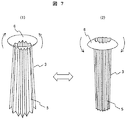
図7(実施例5)はベローズ式の別の形態に係る管体(チムニー)3である。この管体(チムニー)3は全長に亘って襞(ひだ)5が形成され、上端に操作フランジ6を有する。操作フランジ6は、外周側が上向きに反ったり、下向きに反ったりするとともにトグル作動をする。したがって、操作フランジ6は、外周側が上向きに反った状態(図7(1))と、下向きに反った状態(図7(2))に切り替え操作され、いずれかの状態で安定するようになっている。
FIG. 7 (Example 5) shows a tubular body (chimney) 3 according to another bellows type. The tubular body (chimney) 3 has a
そして、操作フランジ6を下向きに反るように下げるとベローズが畳まれ下端径が縮小し、操作フランジ6を上向きに反るように上げるとベローズが開き元に戻るようになっている。 When the operation flange 6 is lowered so as to bend downward, the bellows is folded and the lower end diameter is reduced, and when the operation flange 6 is raised so as to be warped upward, the bellows is opened.
管体(チムニー)3の挿入作業を人手で行うとき、試薬と接触することになる管体(チムニー)3の下端部を手で触れることは、あまり好ましいことではない。手袋をして作業するなどの手法もあるが、操作フランジ6を備えたベローズ式の構造とすることで、接液箇所(下端部を)に直接手を触れずに管体(チムニー)の装着作業を行うことができる。 When the tube body (chimney) 3 is inserted manually, it is not very preferable to touch the lower end portion of the tube body (chimney) 3 to be in contact with the reagent by hand. There are techniques such as working with gloves, but by adopting a bellows type structure with an operation flange 6, the pipe body (chimney) can be attached without touching the wetted part (lower end) directly. Work can be done.
また、管体(チムニー)が末広がり構造になることで、管体(チムニー)の浮上り防止の効果も得られる。 Further, since the tubular body (chimney) has a divergent structure, the effect of preventing the tubular body (chimney) from being lifted can be obtained.
管体(チムニー)の材料をポリエチレンやポリプロピレンのような比重の小さい材料とした場合、特に比重の大きな試薬にて、管体(チムニー)に働く浮力によりこれが浮上ってしまう恐れがあり、その場合、浮上った管体(チムニー)と試薬の分注ノズルが接触する危険性がある。管体(チムニー)の外径が試薬容器の上開口部より大きい末広がり構造であれば、管体(チムニー)が引っかかり、浮上りを防止できる。 If the material of the tube (chimney) is made of a material with a low specific gravity such as polyethylene or polypropylene, it may rise due to the buoyancy acting on the tube (chimney), especially with a reagent with a large specific gravity There is a risk that the tube (chimney) that has floated and the reagent dispensing nozzle come into contact with each other. If the outer diameter of the tube (chimney) is larger than the upper opening of the reagent container, the tube (chimney) is caught and can be prevented from rising.
図9(実施例6)に示す管体(チムニー)3は、下側に下がるにつれて段階的に径大する形状を有する。異径段は3段であるが、2段または4段以上することも可能である。また、弾性変形ができるようにゴム、可撓性の合成樹脂で形成したり、スリットや襞をつけることも可能である。 A tubular body (chimney) 3 shown in FIG. 9 (Example 6) has a shape that gradually increases in diameter as it goes down. The different diameter stages are three stages, but two stages or four stages or more are also possible. Further, it can be formed of rubber or flexible synthetic resin so as to be elastically deformed, or can be provided with slits or wrinkles.
図10(実施例7)、図11(実施例8)、図12(実施例9)は管体(チムニー)3の抜け防止に係るものである。 10 (Embodiment 7), FIG. 11 (Embodiment 8), and FIG. 12 (Embodiment 9) relate to prevention of the tube (chimney) 3 from coming off.
図10(実施例7)の(1)に示される管体(チムニー)3は外周に係合突起60を有する。係合突起60は管体(チムニー)3の中途高さに設けられる。管体(チムニー)3の上端外周には、落下防止をするフランジ20が設けられる。
The tubular body (chimney) 3 shown in (1) of FIG. 10 (Example 7) has an engaging
管体(チムニー)3は図10の(2)に示す試薬容器1の上開口部に挿入される。挿入された管体(チムニー)3は図10の(3)に示すように試薬容器内に装着される。係合突起60が上開口部の内側下端縁に係合して管体(チムニー)3の抜け止めになる。
The tube (chimney) 3 is inserted into the upper opening of the
管体(チムニー)3は係合突起60があるので、試薬容器1の上開口部に強く押し付けて挿入する。管体(チムニー)3が勢い付いて挿入されてもフランジ20でストップされ、試薬容器1内への管体(チムニー)3の落下防止は図られる。
Since the tube body (chimney) 3 has the
図11(実施例8)の(1)に示される管体(チムニー)3は、上端に外筒70を有する。外筒70は内周に雌ねじを有する。図11の(2)に示すように、試薬容器1は上開口部をもつ開口筒部71を有する。容器蓋体72は開口筒部71の蓋である(図11の(3))。
A tubular body (chimney) 3 shown in FIG. 11 (Embodiment 8) (1) has an
開口筒部71は外周に雄ねじを有する。容器蓋体72は開口筒部71の雄ねじに螺合する雌ねじを有する。開口筒部71の雄ねじには、外筒70の雌ねじも螺合する。
The
図11の(4)に示すように、試薬容器1から容器蓋体72を外し、管体(チムニー)3を試薬容器1に取り付ける。そして、管体(チムニー)3の外筒70を開口筒部71にねじ込んで固定する。この固定で管体(チムニー)3は試薬容器1に抜け止めされる。
As shown in FIG. 11 (4), the
図12(実施例9)の(1)に示される管体(チムニー)3は、外周に雄ねじを有する。図12の(2)に示すように、試薬容器1は中央に上開口部をもつ開口筒部80を有する。開口筒部80は、外周に雄ねじ、内周に雌ねじを有する。容器蓋体81は開口筒部80の蓋で、これの内周に開口筒部80の雄ねじに螺合する雌ねじを有する。
The tubular body (chimney) 3 shown in FIG. 12 (Example 9) (1) has a male screw on the outer periphery. As shown in (2) of FIG. 12, the
図12の(3)に示すように、試薬容器1から容器蓋体81を外す。そして、管体(チムニー)3を試薬容器1に取り付ける(図12の(4))、管体(チムニー)3を開口筒部80にねじ込んで固定する。この固定で管体(チムニー)3は試薬容器1に抜け止めされる。
As shown in FIG. 12 (3), the
また、管体(チムニー)3が開口筒部80に取り付けられている上から容器蓋体81を開口筒部80にねじ込むことができるので、容器蓋体81による閉鎖は管体(チムニー)3を外さなくてもでき、取り扱い易い。
In addition, since the
1…試薬容器
2…試薬(液体)
3…管体(チムニー)
4…スリット
5…襞(ひだ)
6…操作フランジ
20…フランジ
101…検体ディスク
102…検体分注装置
103…反応セル
104…反応ディスク
105…試薬ディスク
106…試薬分注装置
107…攪拌機構
108…光度計
109…洗浄機構
1 ...
3 ... Tube (chimney)
4 ...
6 ...
Claims (6)
前記管体の内部通路断面積は上端側よりも下端側が大きく、且つ、前記管体は、弾性体よりなり、前記上開口部から試薬容器内部に挿入される被挿入部分が前記上開口部の内径より大きい外径を有し、この被挿入部分が自身の弾性によりスリット無しで縮み変形して前記上開口部から挿入され、前記試薬容器内部で弾性復元により拡径構造を呈していることを特徴とする試薬容器。 A reagent container comprising a tube inserted from an upper opening,
Internal cross-sectional area of the pipe body rather large, lower side than the upper end, and, the tubular body is made of an elastic body, the insertion portion to be inserted into the reagent container from the upper opening the upper opening The inserted portion has an outer diameter larger than the inner diameter, and is inserted into the upper opening by contracting and deforming without a slit due to its own elasticity, and has an expanded structure by elastic recovery inside the reagent container. A reagent container characterized by
前記管体の内部通路断面積は上端側から下端側に向かって次第に大きくなることを特徴とする試薬容器。 The reagent container according to claim 1, wherein
The reagent container according to claim 1, wherein the cross-sectional area of the internal passage of the tube gradually increases from the upper end side toward the lower end side.
前記管体の内部通路の内径dと、上端側から試薬容器内の試薬液面までの距離Lとの間にL=C・(d2/4)の関係を満たすことを特徴とする試薬容器。
但し、Cは比例定数である。 The reagent container according to claim 1, wherein
Reagent container, wherein the inner diameter d of the internal passage of the tubular body, to satisfy the relationship of L = C · (d 2/ 4) between the distance L from the upper end to the reagent liquid surface in the reagent container .
However, C is a proportionality constant.
前記管体に前記弾性を付ける、長手方向に延在する襞を有することを特徴とする試薬容器。 The reagent container according to claim 1 , wherein
A reagent container having a ridge extending in a longitudinal direction for imparting the elasticity to the tube body.
前記管体の内部通路断面積は上端側よりも下端側が大きく、
前記管体は、前記上開口部の内径より大きい外径を有し、前記管体は、襞が長手方向の全長に亘って形成され、上端に外周側が上向きに反ったり、下向きに反ったりするトグル作動をする操作フランジを備え、
前記操作フランジを下向きに反らして前記管体の下端側が先細りになるように縮め、先細になった下端側の方より前記管体を前記開口部に挿入し、管体が試薬容器の奥まで入ったら前記操作フランジを上向きに反らして管体の下端側が拡がり拡径構造を呈していることを特徴とする試薬容器。 A reagent container comprising a tube inserted from an upper opening,
The internal passage cross-sectional area of the tubular body is larger on the lower end side than the upper end side,
The tubular body has an outer diameter larger than the inner diameter of the upper opening, and the tubular body has a ridge formed over the entire length in the longitudinal direction , and the outer peripheral side warps upward or warps downward at the upper end. It has an operating flange that toggles,
The operation flange is warped downward and is shrunk so that the lower end side of the tube body is tapered, and the tube body is inserted into the opening from the tapered lower end side so that the tube body enters to the back of the reagent container. Then, the operation flange is warped upward, and the lower end side of the tubular body is expanded to exhibit a diameter expansion structure .
前記管体を形成する材料はポリエチレンまたはポリプロピレンであることを特徴とする試薬容器。 A reagent container according to any one of claims 1 to 5 ,
A reagent container characterized in that the material forming the tube is polyethylene or polypropylene.
Priority Applications (1)
| Application Number | Priority Date | Filing Date | Title |
|---|---|---|---|
| JP2009254880A JP5242537B2 (en) | 2009-11-06 | 2009-11-06 | Reagent container and reagent container tube |
Applications Claiming Priority (1)
| Application Number | Priority Date | Filing Date | Title |
|---|---|---|---|
| JP2009254880A JP5242537B2 (en) | 2009-11-06 | 2009-11-06 | Reagent container and reagent container tube |
Publications (2)
| Publication Number | Publication Date |
|---|---|
| JP2011099769A JP2011099769A (en) | 2011-05-19 |
| JP5242537B2 true JP5242537B2 (en) | 2013-07-24 |
Family
ID=44191057
Family Applications (1)
| Application Number | Title | Priority Date | Filing Date |
|---|---|---|---|
| JP2009254880A Active JP5242537B2 (en) | 2009-11-06 | 2009-11-06 | Reagent container and reagent container tube |
Country Status (1)
| Country | Link |
|---|---|
| JP (1) | JP5242537B2 (en) |
Families Citing this family (8)
| Publication number | Priority date | Publication date | Assignee | Title |
|---|---|---|---|---|
| USD978375S1 (en) | 2013-03-13 | 2023-02-14 | Abbott Laboratories | Reagent container |
| US9535082B2 (en) | 2013-03-13 | 2017-01-03 | Abbott Laboratories | Methods and apparatus to agitate a liquid |
| US10058866B2 (en) | 2013-03-13 | 2018-08-28 | Abbott Laboratories | Methods and apparatus to mitigate bubble formation in a liquid |
| USD962471S1 (en) | 2013-03-13 | 2022-08-30 | Abbott Laboratories | Reagent container |
| JP6196089B2 (en) * | 2013-07-24 | 2017-09-13 | シスメックス株式会社 | Reagent container transfer container and analyzer container set |
| WO2017163567A1 (en) * | 2016-03-22 | 2017-09-28 | 富士フイルム株式会社 | Solution discharge device and solution-discharge controlling method |
| CN212881367U (en) * | 2016-12-08 | 2021-04-06 | 反应分析公司 | Sample vial assembly and filter insert |
| CN110392835A (en) * | 2017-03-31 | 2019-10-29 | 积水医疗株式会社 | Reagent container connector |
Family Cites Families (12)
| Publication number | Priority date | Publication date | Assignee | Title |
|---|---|---|---|---|
| JPH01111657A (en) * | 1987-10-14 | 1989-04-28 | Fuji Photo Film Co Ltd | Concentration preventive container |
| JPH075179A (en) * | 1992-05-27 | 1995-01-10 | Hidekazu Sakakibara | Partition for reagent preserving vessel |
| DE19536789A1 (en) * | 1995-10-02 | 1997-04-03 | Boehringer Mannheim Gmbh | Vessel for liquids |
| JP2002019855A (en) * | 2000-07-04 | 2002-01-23 | Olympus Optical Co Ltd | Adapter and container with adapter |
| JP2003329688A (en) * | 2002-05-10 | 2003-11-19 | Fujirebio Inc | Cap, reagent container therewith, and method of preventing evaporation, etc., of reagent using it |
| US7726180B2 (en) * | 2005-03-28 | 2010-06-01 | Kurume University | Float and liquid container using the float, method for preventing malfunction of probe in automatic analyzer, and examination method using automatic analyzer |
| JP2007046998A (en) * | 2005-08-09 | 2007-02-22 | Hitachi High-Technologies Corp | Chemical analyzer, and reagent device for use therein |
| DE102006021404A1 (en) * | 2006-05-08 | 2007-11-15 | Roche Diagnostics Gmbh | Liquid container with removal chimney |
| US20080017577A1 (en) * | 2006-07-21 | 2008-01-24 | Becton, Dickinson And Company | Membrane-based Double-layer Tube for Sample Collections |
| JP3128511U (en) * | 2006-09-01 | 2007-01-18 | 瑛子 林 | Plastic bottle caps |
| JP2008096223A (en) * | 2006-10-10 | 2008-04-24 | Sysmex Corp | Analyzer |
| EP1998180A1 (en) * | 2007-05-31 | 2008-12-03 | F.Hoffmann-La Roche Ag | Fluid container with variable flue |
-
2009
- 2009-11-06 JP JP2009254880A patent/JP5242537B2/en active Active
Also Published As
| Publication number | Publication date |
|---|---|
| JP2011099769A (en) | 2011-05-19 |
Similar Documents
| Publication | Publication Date | Title |
|---|---|---|
| JP5242537B2 (en) | Reagent container and reagent container tube | |
| EP3116824B1 (en) | Vented tap dispenser for liquid | |
| PT2043922E (en) | Spout for ensuring evacuation of a flexible container | |
| JP4669924B2 (en) | Automatic valve assembly for chilled water storage | |
| JP5551646B2 (en) | Refill container | |
| US20100013897A1 (en) | Ink cartridge for inkjet printers | |
| US9975751B2 (en) | Collection funnel | |
| JP2011506218A (en) | Vial cap 187 | |
| JP6454290B2 (en) | Liquid container | |
| KR20160139916A (en) | The container controlling the quantity of its content | |
| KR101454748B1 (en) | The container controlling the quantity of its content | |
| US20220008915A1 (en) | Specimen container and cap | |
| US20220008916A1 (en) | Specimen container and cap | |
| JPH0544596U (en) | Filling device for writing liquid supply device | |
| JP2017049034A (en) | Cap open/close auxiliary device of test container | |
| KR101451601B1 (en) | The container controlling the quantity of its content | |
| WO2017043367A1 (en) | Pipette cap and pipette container provided with same | |
| KR101713048B1 (en) | The container controlling the quantity of its content | |
| US9108191B2 (en) | Device and method for the complete uptake of liquids from vessels | |
| CN219057055U (en) | Pollution-proof closing device for reagent container | |
| KR100836068B1 (en) | Inner cap for vessel for liquid | |
| CN209530920U (en) | A kind of pipette tips box | |
| JPH063815Y2 (en) | Pouring cap | |
| WO2015151253A1 (en) | Packaging container | |
| US20130133132A1 (en) | Container for the Collection of Urine Over a Period of 24 Hours |
Legal Events
| Date | Code | Title | Description |
|---|---|---|---|
| A621 | Written request for application examination |
Free format text: JAPANESE INTERMEDIATE CODE: A621 Effective date: 20120113 |
|
| A977 | Report on retrieval |
Free format text: JAPANESE INTERMEDIATE CODE: A971007 Effective date: 20121130 |
|
| A131 | Notification of reasons for refusal |
Free format text: JAPANESE INTERMEDIATE CODE: A131 Effective date: 20121211 |
|
| A521 | Written amendment |
Free format text: JAPANESE INTERMEDIATE CODE: A523 Effective date: 20130212 |
|
| TRDD | Decision of grant or rejection written | ||
| A01 | Written decision to grant a patent or to grant a registration (utility model) |
Free format text: JAPANESE INTERMEDIATE CODE: A01 Effective date: 20130326 |
|
| A61 | First payment of annual fees (during grant procedure) |
Free format text: JAPANESE INTERMEDIATE CODE: A61 Effective date: 20130403 |
|
| FPAY | Renewal fee payment (event date is renewal date of database) |
Free format text: PAYMENT UNTIL: 20160412 Year of fee payment: 3 |
|
| R150 | Certificate of patent or registration of utility model |
Free format text: JAPANESE INTERMEDIATE CODE: R150 |