JP5236133B2 - Method and apparatus for recording and dynamically configuring performance analysis of medical diagnostic imaging systems - Google Patents
Method and apparatus for recording and dynamically configuring performance analysis of medical diagnostic imaging systems Download PDFInfo
- Publication number
- JP5236133B2 JP5236133B2 JP2000317249A JP2000317249A JP5236133B2 JP 5236133 B2 JP5236133 B2 JP 5236133B2 JP 2000317249 A JP2000317249 A JP 2000317249A JP 2000317249 A JP2000317249 A JP 2000317249A JP 5236133 B2 JP5236133 B2 JP 5236133B2
- Authority
- JP
- Japan
- Prior art keywords
- medical diagnostic
- diagnostic imaging
- performance
- data
- imaging system
- Prior art date
- Legal status (The legal status is an assumption and is not a legal conclusion. Google has not performed a legal analysis and makes no representation as to the accuracy of the status listed.)
- Expired - Lifetime
Links
- 238000002059 diagnostic imaging Methods 0.000 title claims description 74
- 238000004458 analytical method Methods 0.000 title claims description 64
- 238000000034 method Methods 0.000 title claims description 7
- 238000012545 processing Methods 0.000 claims description 27
- 238000005070 sampling Methods 0.000 claims description 13
- 239000000872 buffer Substances 0.000 claims description 5
- 238000013523 data management Methods 0.000 description 6
- 238000010586 diagram Methods 0.000 description 6
- 238000012986 modification Methods 0.000 description 4
- 230000004048 modification Effects 0.000 description 4
- 238000010521 absorption reaction Methods 0.000 description 2
- 238000011961 computed axial tomography Methods 0.000 description 2
- 230000007547 defect Effects 0.000 description 2
- 231100000206 health hazard Toxicity 0.000 description 2
- 230000005855 radiation Effects 0.000 description 2
- 238000003324 Six Sigma (6σ) Methods 0.000 description 1
- 238000004364 calculation method Methods 0.000 description 1
- 238000004891 communication Methods 0.000 description 1
- 239000012141 concentrate Substances 0.000 description 1
- 230000001276 controlling effect Effects 0.000 description 1
- 238000012937 correction Methods 0.000 description 1
- 238000013480 data collection Methods 0.000 description 1
- 230000007423 decrease Effects 0.000 description 1
- 238000001514 detection method Methods 0.000 description 1
- 239000003814 drug Substances 0.000 description 1
- 238000011156 evaluation Methods 0.000 description 1
- 238000003384 imaging method Methods 0.000 description 1
- 238000002955 isolation Methods 0.000 description 1
- 230000007774 longterm Effects 0.000 description 1
- 238000002595 magnetic resonance imaging Methods 0.000 description 1
- 238000004519 manufacturing process Methods 0.000 description 1
- 238000005259 measurement Methods 0.000 description 1
- 238000012544 monitoring process Methods 0.000 description 1
- 230000001105 regulatory effect Effects 0.000 description 1
- 238000011160 research Methods 0.000 description 1
- 238000007619 statistical method Methods 0.000 description 1
- 239000012536 storage buffer Substances 0.000 description 1
- 238000002604 ultrasonography Methods 0.000 description 1
Images


Classifications
-
- G—PHYSICS
- G16—INFORMATION AND COMMUNICATION TECHNOLOGY [ICT] SPECIALLY ADAPTED FOR SPECIFIC APPLICATION FIELDS
- G16H—HEALTHCARE INFORMATICS, i.e. INFORMATION AND COMMUNICATION TECHNOLOGY [ICT] SPECIALLY ADAPTED FOR THE HANDLING OR PROCESSING OF MEDICAL OR HEALTHCARE DATA
- G16H40/00—ICT specially adapted for the management or administration of healthcare resources or facilities; ICT specially adapted for the management or operation of medical equipment or devices
- G16H40/40—ICT specially adapted for the management or administration of healthcare resources or facilities; ICT specially adapted for the management or operation of medical equipment or devices for the management of medical equipment or devices, e.g. scheduling maintenance or upgrades
-
- G—PHYSICS
- G16—INFORMATION AND COMMUNICATION TECHNOLOGY [ICT] SPECIALLY ADAPTED FOR SPECIFIC APPLICATION FIELDS
- G16H—HEALTHCARE INFORMATICS, i.e. INFORMATION AND COMMUNICATION TECHNOLOGY [ICT] SPECIALLY ADAPTED FOR THE HANDLING OR PROCESSING OF MEDICAL OR HEALTHCARE DATA
- G16H30/00—ICT specially adapted for the handling or processing of medical images
- G16H30/20—ICT specially adapted for the handling or processing of medical images for handling medical images, e.g. DICOM, HL7 or PACS
-
- Y—GENERAL TAGGING OF NEW TECHNOLOGICAL DEVELOPMENTS; GENERAL TAGGING OF CROSS-SECTIONAL TECHNOLOGIES SPANNING OVER SEVERAL SECTIONS OF THE IPC; TECHNICAL SUBJECTS COVERED BY FORMER USPC CROSS-REFERENCE ART COLLECTIONS [XRACs] AND DIGESTS
- Y10—TECHNICAL SUBJECTS COVERED BY FORMER USPC
- Y10S—TECHNICAL SUBJECTS COVERED BY FORMER USPC CROSS-REFERENCE ART COLLECTIONS [XRACs] AND DIGESTS
- Y10S128/00—Surgery
- Y10S128/92—Computer assisted medical diagnostics
- Y10S128/922—Computer assisted medical diagnostics including image analysis
Landscapes
- Health & Medical Sciences (AREA)
- Engineering & Computer Science (AREA)
- Medical Informatics (AREA)
- Epidemiology (AREA)
- General Health & Medical Sciences (AREA)
- Primary Health Care (AREA)
- Public Health (AREA)
- Business, Economics & Management (AREA)
- Biomedical Technology (AREA)
- General Business, Economics & Management (AREA)
- Radiology & Medical Imaging (AREA)
- Nuclear Medicine, Radiotherapy & Molecular Imaging (AREA)
- Apparatus For Radiation Diagnosis (AREA)
- Medical Treatment And Welfare Office Work (AREA)
Description
本発明は一般的には、医療診断イメージング・システム・データを記録(ログ)して分析するシステムに関する。より具体的には、本発明は、シックス・シグマ研究用等の医療診断イメージング・システム・データの性能分析を記録し動的に構成するシステムに関する。 The present invention generally relates to a system for recording and analyzing medical diagnostic imaging system data. More specifically, the present invention relates to a system for recording and dynamically configuring performance analysis of medical diagnostic imaging system data, such as for Six Sigma research.
診断イメージングから得られる情報は、医学及び製造業を含めた多くの分野で応用されている。医療診断イメージング・システム、例えば、X線システム、超音波システム、磁気共鳴イメージング(MRI)システム及び計算機式アキシャル断層撮影(CAT)システム等は典型的には、ソースと検出器とを含んでいる。人体等の観察したい目標物がソースと検出器との間に配置される。ソースは媒体を送出し、媒体は目標物を通過して検出器に到達する。媒体がソースから目標物を通過走行するのに伴って、目標物の内部成分が媒体に対して、媒体の遮蔽又は吸収等の現象を通じて媒体のエネルギを様々な程度にまで減少させるといった影響を及ぼし得る。目標物の内部でのX線等の媒体の遮蔽又は吸収により、受け取られるエネルギ・レベルが変化する。検出器は、目標物を通過したエネルギ又は目標物から反射したエネルギを受け取る。検出器において検出されたエネルギに基づいて、目標物の画像が形成される。形成された画像は、目標物を通過したエネルギ又は目標物から反射したエネルギの様々な強度レベルに対応する明るい領域及び暗い領域を含む。 Information obtained from diagnostic imaging has been applied in many fields, including medicine and manufacturing. Medical diagnostic imaging systems, such as x-ray systems, ultrasound systems, magnetic resonance imaging (MRI) systems, computed axial tomography (CAT) systems, and the like, typically include a source and a detector. A target to be observed such as a human body is placed between the source and the detector. The source delivers the medium, which passes through the target and reaches the detector. As the medium travels through the target from the source, the internal components of the target affect the medium, reducing the energy of the medium to various degrees through phenomena such as shielding or absorption of the medium. obtain. Shielding or absorption of media such as x-rays inside the target changes the received energy level. The detector receives energy that has passed through or reflected from the target. An image of the target is formed based on the energy detected at the detector. The formed image includes bright and dark areas corresponding to various intensity levels of energy that has passed through or reflected from the target.
上述の一般的な形式のシステムによって形成される医療診断画像は、多くの目的に用いることができる。例えば、目標物の内部欠陥を検出することができる。加えて、内部の構造又は整列性の変化を決定することもできる。更に、画像は、目標物内部の物体の存在又は非在を示すこともできる。 Medical diagnostic images formed by the general types of systems described above can be used for many purposes. For example, an internal defect of the target can be detected. In addition, changes in internal structure or alignment can also be determined. Furthermore, the image can also indicate the presence or absence of an object inside the target.
医療診断画像を高い信頼性で利用し得るとの保証を支援するために、医療診断イメージング・システムの性能を測定して実証すると有利である。具体的には、医療診断イメージング・システムの画質を測定して実証することが重要である。画質が不十分であると、医療診断画像の信頼性のある分析が妨げられる虞がある。例えば、画像コントラスト品質が低下すると、利用できないような信頼性の低い画像が形成され得る。加えて、実時間イメージング・システムの出現により、明瞭で且つ高品質の画像を形成する重要性が高まっている。画質が不十分であったり又は劣化したりしているような医療診断イメージング・システムは、目標物の明瞭で且つ利用可能な表現を形成するように最較正されねばならない。 It is advantageous to measure and demonstrate the performance of a medical diagnostic imaging system to help ensure that medical diagnostic images can be used reliably. Specifically, it is important to measure and demonstrate the image quality of a medical diagnostic imaging system. Insufficient image quality may interfere with reliable analysis of medical diagnostic images. For example, when the image contrast quality decreases, an unreliable image that cannot be used can be formed. In addition, with the advent of real-time imaging systems, the importance of producing clear and high quality images is increasing. Medical diagnostic imaging systems that have poor or degraded image quality must be recalibrated to form a clear and usable representation of the target.
また、安全性の理由から医療診断イメージング・システムの性能を実証することも重要である。例えば、高レベルのエネルギの照射は、人体に対して何らかの健康危険を伴う場合がある。この健康危険のため、幾つかの医療診断イメージング・システムの利用に対しては政府標準規格が設けられている。例えば、医療診断イメージング・システムによって放出されるX線エネルギのレベルは、放射線量によって測定することができる。医療診断イメージング・システムを定期的に性能評価することにより、目標物を照射する放射線量が規制標準を超えていないことが保証される。 It is also important to demonstrate the performance of medical diagnostic imaging systems for safety reasons. For example, irradiation with a high level of energy may involve some health hazard to the human body. Because of this health hazard, government standards have been established for the use of several medical diagnostic imaging systems. For example, the level of x-ray energy emitted by a medical diagnostic imaging system can be measured by radiation dose. Regular performance evaluation of medical diagnostic imaging systems ensures that the radiation dose to the target does not exceed regulatory standards.
加えて、いずれの性能に更なる修正による改良の余地があるかを決定するために医療診断イメージング・システムの性能を監視することもできる。ネットワーク帯域幅又はディスク速度等のシステム・パラメータが性能仕様に合致していないならば、性能データを用いて医療診断イメージング・システムに対する変更を支援することができる。同様に、問題点又は欠陥を医療診断イメージング・システム内の具体的な構成要素又はサブシステムに分離特定するのに性能データが役立つ。また、駆動電流、電圧及び温度等のパラメータのゆらぎを検出することにより、摩耗を識別すると共に将来のシステム故障を予防するのを支援することもできる。 In addition, the performance of the medical diagnostic imaging system can be monitored to determine which performance can be improved by further modifications. If system parameters such as network bandwidth or disk speed do not meet performance specifications, performance data can be used to assist in changes to the medical diagnostic imaging system. Similarly, performance data is useful for isolating problems or defects into specific components or subsystems within a medical diagnostic imaging system. Also, by detecting fluctuations in parameters such as drive current, voltage and temperature, it is possible to identify wear and assist in preventing future system failures.
従来、医療診断イメージング・システムは、性能分析を行なうのに制限された能力しか提供していない。医療診断イメージング・システム・データを収集する現在のシステムは、データを収集することが望ましいようなありとあらゆる所望のパラメータ変数(例えば、温度、電圧、電流等)によって予めプログラムしておかなければならない。医療診断イメージング・システムについて収集されるデータの量又は形式を変更するためには、技術者が現場でシステムを手動で構成し直すか又はシステムのソフトウェアをプログラムし直さなければならない。例えば、第1の組のパラメータ(例えば、検出器電圧及び電流)を分析すると、第2の組のパラメータに問題が存在している可能性があることが指示されたならば、現場でシステムを手動で構成し直さなければならない。手動での構成のし直し(recofiguration)は、第2の組のパラメータを含めるようにシステムの診断ソフトウェア又はアプリケーション・ソフトウェアを書き直すことを含み得る。 Traditionally, medical diagnostic imaging systems provide limited ability to perform performance analysis. Current systems that collect medical diagnostic imaging system data must be preprogrammed with any and all desired parameter variables (eg, temperature, voltage, current, etc.) for which it is desirable to collect data. In order to change the amount or format of data collected for a medical diagnostic imaging system, a technician must either manually reconfigure the system in the field or reprogram the system software. For example, if analysis of a first set of parameters (eg, detector voltage and current) indicates that a problem may exist with the second set of parameters, the system can be Must be manually reconfigured. Manual reconfiguration may include rewriting the system's diagnostic software or application software to include a second set of parameters.
加えて、従来の医療診断イメージング・システムは、予め設定されたサンプリング速度(例えば、患者毎、1分間毎、1秒間毎等)でデータを収集するように予めプログラムしておかなければならない。パラメータ変数データは、所定のサンプリング速度又は周波数で収集されて記録される。データ収集及び記録のサンプリング速度は、技術者が現場でシステムを手動で構成し直さない限り変更することはできない。例えば、分析用に受け取るデータの量を減少させる又は増大させるためには、システムを現場で手動で調節しなければならない。パラメータ変数のサンプリング速度の手動での調節は、システムの診断ソフトウェアの修正を含み得る。 In addition, conventional medical diagnostic imaging systems must be preprogrammed to collect data at a preset sampling rate (eg, per patient, every minute, every second, etc.). The parameter variable data is collected and recorded at a predetermined sampling rate or frequency. The sampling rate for data collection and recording cannot be changed unless the technician manually reconfigures the system in the field. For example, to reduce or increase the amount of data received for analysis, the system must be manually adjusted in the field. Manual adjustment of the sampling rate of the parameter variable may include modification of the system diagnostic software.
システムを現場で手動で構成し直すことは、医療診断イメージング・システムのエラーの分離特定及び補正を不必要に複雑化する。加えて、技術者が現場で手動で構成し直す必要性から、正確なエラー検出を行なうのに必要な時間、費用及び人員の量が増大する。 Manually reconfiguring the system in the field unnecessarily complicates the isolation and correction of errors in medical diagnostic imaging systems. In addition, the need for technicians to manually reconfigure on-site increases the time, expense, and amount of personnel required to perform accurate error detection.
このように、医療診断イメージング・システムの性能データを自動的に記録し分析することの可能なシステムに対する需要が長らく存在していた。加えて、医療診断システムの様々な量又は形式の性能データを記録し分析するように容易に構成し直すことのできるシステムに対する需要が長らく存在していた。また、医療診断イメージング・システムの選択されたデータ集合の様々な特性を記録し分析することのできるシステムに対する需要が長らく存在していた。本発明の好適実施例は、これらの需要、及び医療診断イメージング・システムを分析する従来のシステムに関連するその他の問題点に対処する。 Thus, there has long been a need for a system that can automatically record and analyze performance data of medical diagnostic imaging systems. In addition, there has long been a need for a system that can be easily reconfigured to record and analyze various amounts or types of performance data for medical diagnostic systems. There also has long been a need for a system that can record and analyze various characteristics of selected data sets of medical diagnostic imaging systems. The preferred embodiment of the present invention addresses these needs and other problems associated with conventional systems for analyzing medical diagnostic imaging systems.
医療診断イメージング・システムの性能データの構成可変の記録及び分析のための方法及びシステムを提供する。医療診断イメージング・システムは、サブシステムに分割することができる。サブシステムは、関連するサブシステムの性能に関する所望の形式のデータを取得するデータ取得モジュールを含んでいる。データ取得モジュールは、医療診断イメージング・システムの動作中に生の性能データ(例えば、温度、電流、電圧等)を取得する。データ取得モジュールは、生の性能データを遠隔で取得することもできる。生の性能データは、所望の形式の性能分析に関連するパラメータを指定した構成(コンフィギュレーション)ファイルに基づいて取得される。新たな構成ファイルを遠隔からダウンロードして、所望の形式の性能分析のための少なくとも1つのパラメータを動的に選択することもできる。構成ファイル内のパラメータは、性能変数及び性能変数のサンプリング速度のうち少なくとも一方を含み得る。 Methods and systems for configurable recording and analysis of performance data of medical diagnostic imaging systems are provided. The medical diagnostic imaging system can be divided into subsystems. The subsystem includes a data acquisition module that acquires the desired type of data regarding the performance of the associated subsystem. The data acquisition module acquires raw performance data (eg, temperature, current, voltage, etc.) during operation of the medical diagnostic imaging system. The data acquisition module can also acquire raw performance data remotely. Raw performance data is obtained based on a configuration file that specifies parameters associated with a desired type of performance analysis. A new configuration file can also be downloaded remotely to dynamically select at least one parameter for the desired type of performance analysis. The parameter in the configuration file may include at least one of a performance variable and a performance variable sampling rate.
処理モジュールが、データ取得モジュールによって取得された生の性能データを処理する。データは、医療診断イメージング・システムの動作中に実時間で処理され得る。処理モジュールは、生の性能データを要約した特性データを生成する。例えば、処理モジュールは、生の性能データに対して傾向統計を計算するか又は統計分析を実行して、特性データを生成することができる。特性データは、最小値、最大値、平均及び標準偏差等のうち少なくとも1つを含み得る。出力モジュールが、医療診断イメージング・システムの性能を識別させる特性データを出力する。出力モジュールは、記憶バッファ、傾向記録、表示器及び中央処理システムのうち少なくとも1つに特性データを出力することができる。 A processing module processes the raw performance data acquired by the data acquisition module. Data can be processed in real time during operation of the medical diagnostic imaging system. The processing module generates characteristic data summarizing the raw performance data. For example, the processing module can calculate trend statistics or perform statistical analysis on the raw performance data to generate characteristic data. The characteristic data may include at least one of a minimum value, a maximum value, an average, a standard deviation, and the like. An output module outputs characteristic data that identifies the performance of the medical diagnostic imaging system. The output module can output the characteristic data to at least one of a storage buffer, a trend record, a display, and a central processing system.
本発明の好適実施例のこれらの特徴及びその他の特徴は、以下の本発明の好適実施例の詳細な説明において議論され明らかとなる。 These and other features of the preferred embodiment of the present invention will be discussed and apparent in the following detailed description of the preferred embodiment of the present invention.
図1は、本発明に従って用いられる医療診断イメージング・システム100の好適実施例を示している。医療診断イメージング・システム100は、複数のサブシステムを含んでいる。説明の目的のためのみとして、医療診断イメージング・システムをX線システムとして記載する。医療診断イメージング・システム100は、X線検出器110、検出器位置調節器115、X線源120、線源位置調節器125、X線発生器130、患者140、患者位置調節器145、配置制御150、画像及び患者データ管理モジュール160、画像表示器165、システム制御器170及び中央処理システム180等のサブシステムを含んでいる。医療診断イメージング・システム100はまた、性能分析モジュール195、パラメータ構成モジュール196、傾向記録データベース197及びファイル記憶媒体198を含んでいる。医療診断イメージング・システム100の各々のサブシステムがデータ取得モジュール190を含み得る。 FIG. 1 illustrates a preferred embodiment of a medical diagnostic imaging system 100 used in accordance with the present invention. The medical diagnostic imaging system 100 includes a plurality of subsystems. For illustrative purposes only, the medical diagnostic imaging system is described as an X-ray system. The medical diagnostic imaging system 100 includes an
各データ取得モジュール190は、医療診断イメージング・システム100の動作中に生の性能データを取得して、この生の性能データを性能分析モジュール195へ供給する。性能分析モジュール195は、医療診断イメージング・システム100の動作中に実時間で生の性能データを処理して、関連するサブシステムの生の性能データを要約した特性データを生成する。性能分析モジュール195はまた、医療診断イメージング・システム100の性能を識別させる特性データを出力する。性能分析モジュール195は、特性データをバッファに記憶することができる。代替的には、性能分析モジュール195は、特性データを傾向記録内に記録することもできるし、又は特性データを表示することもできるし、且つ/又は中央処理システム180へ特性データを送信することもできる。傾向記録は、中央処理装置180又はその他の位置に設けられているデータベース197に記憶することができる。性能分析モジュール195は、生の性能データに基づいて特性データとして傾向統計を計算する。傾向統計の計算は、特性データとして生の性能データの最小値、最大値、平均及び標準偏差等のうち少なくとも1つを算出することを含み得る。 Each
生の性能データは、例えば、電圧、温度、画質、性能、摩耗部品及び利用状況等の様々なパラメータ・クラスに分類され得る。電圧パラメータ・クラスは、1つ又はこれよりも多いデータ取得モジュール190によって様々なサブシステムから得られた1つ又はこれよりも多い電圧値を表わし得る。1つ又はこれよりも多いサブシステムから電圧データを得ることにより、性能分析モジュール195は、システムの全体にわたる電圧のゆらぎを証拠付ける電圧パラメータ・クラスの特性データ集合を形成することができる。利用者は、これらの電圧のゆらぎを分析して、故障を検出したり性能を分析したりすることができる。 Raw performance data can be classified into various parameter classes such as, for example, voltage, temperature, image quality, performance, wear parts and usage. The voltage parameter class may represent one or more voltage values obtained from various subsystems by one or more
温度パラメータは、熱のゆらぎが環境に起因するものであるか又はシステムの利用状況等に起因するものであるか否かを決定するために様々なサブシステム内でクラスとして監視され得る。画質パラメータは、管出力等の画質に関わる生の性能データを提供する。性能パラメータ・クラスは、ネットワーク帯域幅及びディスク速度等の生の性能データを表わす。性能パラメータ・クラスは、システムが所望の速度で稼働していない場合に関心の対象となり得る。性能が不十分である理由には、間欠的な時間中断による場合又は性能仕様を超えている場合等がある。摩耗部品パラメータ・クラスは、部品の機械的摩耗及び電気的摩耗の測定に関わる生の性能データを含んでいる。例としては、部品摩耗に関わる生の性能データは、例えば回転子駆動電流及びフィラメント駆動等からサブシステムの全体にわたって得られる駆動電流に対応し得る。駆動電流を監視することにより、摩耗が機械的摩擦抵抗又は電気抵抗等の過剰な抵抗に起因しているか否かを識別す-ることが可能になる。利用状況パラメータ・クラスは、照射回数又は蓄積線量等のシステムの利用状況を測定するのに用いることができる。利用状況パラメータは、独立した傾向変数を表わしており、システム履歴を保守するのに用いることができる。 The temperature parameter can be monitored as a class within the various subsystems to determine if the thermal fluctuation is due to the environment or due to system usage or the like. The image quality parameter provides raw performance data related to image quality such as tube output. The performance parameter class represents raw performance data such as network bandwidth and disk speed. Performance parameter classes can be of interest when the system is not operating at the desired speed. Reasons for insufficient performance include intermittent time interruptions or exceeding performance specifications. The worn part parameter class contains raw performance data related to the measurement of mechanical and electrical wear of the part. As an example, raw performance data relating to component wear may correspond to drive currents obtained throughout the subsystem from, for example, rotor drive current and filament drive. By monitoring the drive current, it is possible to identify whether the wear is due to excessive resistance such as mechanical frictional resistance or electrical resistance. The usage parameter class can be used to measure the usage status of the system, such as the number of irradiations or accumulated dose. Usage status parameters represent independent trend variables and can be used to maintain system history.
動作中に、性能分析モジュール195は、各々のデータ取得モジュール190に対して、所望の数のパラメータに関する生の性能データを取得するように指令する。性能分析モジュール195は更に、データ取得モジュール190に対して、所定のデータ取得速度で生の性能データを取得するように指令する。具体的なパラメータ及びデータ取得速度を制御することにより、性能分析モジュール195は、記録された生の性能データを要約して傾向分析するための生の性能データの時間的なきめ細かさ及び長期網羅範囲を最適化することができる。 In operation, the
図1は更に、構成ファイル記憶媒体198と連絡しているパラメータ構成モジュール196を示している。パラメータ構成モジュール196は、医療診断イメージング・システム100の性能分析を動的に構成する。上述のように、医療診断イメージング・システム内のサブシステムのうち少なくとも1つのサブシステムが、1つ又はこれよりも多いサブシステムの性能に関連する複数のパラメータに関する生の性能データを取得することが可能なデータ取得モジュール190を含んでいる。パラメータ構成モジュール196は、対応する形式の性能分析に関連して予め定義されているパラメータ構成に基づいて少なくとも1つのパラメータを動的に選択する。対応する形式の性能分析は、利用者によって定義されたものであってもよいし、又は構成ファイル記憶媒体198から自動的に得られたものであってもよい。 FIG. 1 further shows a
より明確に述べると、構成モジュール196は、媒体198又はその他の位置から、所望の形式の性能分析に関連するパラメータを指定したダウンロード可能な構成ファイルを受け取る。構成モジュール196は、所望の形式の性能分析に関連する1組のパラメータを選択する。選択によっては、パラメータ構成モジュール196は、対応する多数の組のパラメータ構成に基づいて多数の組のパラメータを選択してもよく、続いて、関連するデータ取得モジュール190の動作を別個に定義する。 More specifically, the
一旦、パラメータ構成モジュール196がデータ取得モジュール190内で用いられるパラメータを定義したら、上述のようにしてデータ取得モジュール190から性能分析モジュール195へ関連する生の性能データが供給される。 Once the
患者140は、患者位置調節器145を用いて医療診断イメージング・システム100に配置される。1つの例示的なシステムでは、線源位置調節器125を用いてX線源120が患者140の下方に配置される。X線検出器110は、検出器位置調節器115を用いて患者140の上方に配置される。配置制御150が、X線源120とX線検出器110との間での患者140の配置を制御する。X線発生器130がX線を発生し、X線はX線源120から送出されて患者140を通過してX線検出器110に到達する。
画像及び患者データ管理モジュール160は、X線検出器110から画像を受け取る。画像及び患者データ管理モジュール160はまた、医療診断イメージング・システム100のサブシステム110、115、120、125、130、145、150及び170からデータを受け取る。画像及び患者データ管理モジュール160は、画像データ、患者データ及びシステム・データを画像表示器165へ送信する。画像及び患者データ管理モジュール160はまた、画像データ、患者データ及びシステム・データを中央処理システム180へ送信する。中央処理システム180は、システム制御器170に対して、医療診断イメージング・システム100のサブシステム110、115、120、125、130、145及び150のパラメータを調節するように指令することができる。 The image and patient
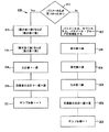
図2は、本発明の好適実施例による医療診断イメージング・システム・データの構成可変の記録及び分析のための流れ図200を示している。ステップ210において、構成ファイルが、媒体198から又は中央処理システム180からパラメータ構成モジュール196へ及び/又は性能分析モジュール195ヘダウンロードされる。ダウンロードされた構成ファイルは、例えば、電圧、温度、タイミング、画質、性能、消耗部品及び利用状況等のパラメータから成る所望の組を含んでいる。1つのパラメータが、パラメータ変数及び該変数のサンプリング速度のうち少なくとも一方を有し得る。 FIG. 2 shows a
ダウンロードされた構成ファイル内のパラメータに基づいて、ステップ212において、性能分析モジュール195及びデータ取得モジュール190は、医療診断イメージング・システム100の1つ又はこれよりも多いサブシステムからの生の性能データの実時間収集を実行する。ステップ214において、性能分析モジュール195内の分析エンジンが生の性能データを分析して特性データを生成する。特性データは、最小値、最大値、平均、相加平均及び標準偏差等を含み得る。ステップ216において、性能分析モジュール195は、特性データをメモリ内の記録ファイルに記憶する。ステップ218において、性能分析モジュール195は、記録ファイル内の関連する特性データを中央処理システム180へ送信する。 Based on the parameters in the downloaded configuration file, in
図3は、医療診断イメージング・システム100の生の性能データを蓄積する好適実施例の流れ図300を示している。ステップ310において、データ取得モジュール190が、選択されたパラメータのデータ値を性能分析モジュール195へ送信する。性能分析モジュール195は、内部データベース197内でパラメータ名を検索する。パラメータ名が見つからない場合には、ステップ322において、性能分析モジュール195は、パラメータ名、データ値が得られた医療診断イメージング・サブシステム名、及びパラメータ・グループ名を用いてデータベース197への新たな項目を初期化する。ステップ324において、性能分析モジュール195はデータ値を最小値として記憶する。ステップ326において、性能分析モジュール195は同じデータ値を最大値として記憶する。ステップ328において、性能分析モジュール195は値の合計を送信されたデータ値に等しく設定する。加えて、ステップ330及びステップ332において、性能分析モジュール195は値の自乗の合計を送信された値の自乗に等しく設定すると共に、サンプル数を1に初期化する。ステップ322〜ステップ332によって、性能分析モジュール195は特定の対応するパラメータについての特性データ集合を初期化している。 FIG. 3 shows a
到来したデータ値に関連するパラメータ名がデータベース197内に見つかった場合には、性能分析モジュール195はデータベース197内の識別されたパラメータの特性データを更新する。ステップ312において、性能分析モジュール195は送信されたデータ値を記憶されている最小値と比較する。対応するパラメータについて記憶されている最小値の方が送信されたデータ値よりも大きい場合には、送信された新たなデータ値を新たな最小値として記憶する。ステップ314において、性能分析モジュール195は送信された新たなデータ値を記憶されている最大値と比較する。記憶されている最大値の方が送信された新たなデータ値よりも小さい場合には、送信されたデータ値を新たな最大値として記憶する。ステップ316において、送信されたデータ値は、記憶されている値の合計に加算される。ステップ318において、性能分析モジュール195は送信されたデータ値を自乗すると共に、該自乗されたデータ値を記憶されている自乗値の合計に加算する。ステップ320において、サンプル数を1だけ増加させる。 If the parameter name associated with the incoming data value is found in the
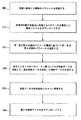
図4は、医療診断イメージング・システム100の特性データの記録の好適実施例の流れ図400を示している。ステップ410において、各々の関連する特性データ毎に、性能分析モジュール195は、記録時刻、パラメータ名、医療診断イメージング・サブシステム名、パラメータ・グループ名、最小値及び最大値等を出力構造に複写する。ステップ412において、性能分析モジュール195は値の合計をサンプル数で除算することにより平均値を算出する。ステップ414において、性能分析モジュール195は、このパラメータ名についてのサンプル数が1よりも大きいか否かを決定する。サンプル数が1よりも大きい場合には、ステップ416において、次の方程式から標準偏差を算出する。 FIG. 4 shows a
標準偏差=SQRT[(自乗値の合計−サンプル数×平均×平均)/
(サンプル数−1)]
サンプル数が1に等しい場合には、ステップ418において、標準偏差を0.0に設定する。ステップ420において、性能分析モジュール195は、平均、標準偏差及びサンプル数を出力構造に複写する。ステップ422において、性能分析モジュール195は、出力構造をデータベース197又は中央処理システム180等に設けられている中央傾向記録に書き込む。ステップ424において、性能分析モジュール195は、値の和、値の自乗の和及びサンプル数等の傾向変数を0に再初期化する。Standard deviation = SQRT [(Square value total−number of samples × average × average) /
(Number of samples-1)]
If the number of samples is equal to 1, in
図5は、医療診断イメージング・システム100の性能分析を動的に構成する代替的な実施例を示している。図5の実施例では、パラメータ構成モジュール196は、医療診断イメージング・システムの性能に関連する複数のパラメータを定義している(ステップ500)。パラメータの例は既に上で述べた。次いで、ステップ510において、システムは、対応する所望の形式の性能分析に関連して定義されたパラメータ構成に基づいてパラメータのうち少なくとも1つを動的に選択する。例えば、ステップ510において、パラメータ構成モジュールは、中央処理システム180から又は構成ファイル記憶媒体198から構成ファイルをダウンロードすることができる。構成ファイルは、所望の形式の性能分析に関連するパラメータを指定している。性能分析の形式は、自動的に選択されてもよいし、利用者によって手動で選択されてもよいし、又はインターネット接続等を介して遠隔で選択されてもよい。ステップ515において、パラメータ構成モジュール196は、第1及び第2の組のパラメータ構成に基づいて第1及び第2の組のパラメータを選択する。パラメータは、性能変数及び該性能変数のサンプリング速度を含み得る。第1及び第2の組のパラメータは、第1及び第2のサブシステム、第1及び第2のパラメータ・クラス、並びに単一のパラメータ・クラスの第1及び第2のサンプリング速度等に対応していてもよい。性能変数の例は既に上で述べた。 FIG. 5 illustrates an alternative embodiment for dynamically configuring the performance analysis of the medical diagnostic imaging system 100. In the example of FIG. 5,
ステップ520において、性能分析モジュール195は、少なくとも1つのパラメータに基づいて生の性能データを分析して、生の性能データを要約した特性データを生成する。分析の例は上で述べられている。ステップ525において、性能分析モジュール195は特性データを中央処理システム180へ送信する。ステップ530において、パラメータ構成モジュール196は新たな構成ファイルをダウンロードして、ステップ510〜ステップ525の処理を繰り返す。 In
本発明の好適実施例は、医療診断イメージング・システムに関わる多くの状況で有用であり得る。例えば、X線システムが低品質の画像を形成しているものと仮定する。先ず、システムは、中央処理システムから構成ファイルをダウンロードして、X線検出器110、検出器位置調節器115、X線源120、線源位置調節器125、X線発生器130、患者位置調節器145、配置制御150及びシステム制御器170から疎らなサンプリング速度でパラメータ変数を検査することができる。初期の1組の生の性能データが、画像及び患者データ管理モジュール160によって収集される。生の性能データを分析した後に、エラーがX線検出器110に位置特定されるとする。そのときには、加速されたサンプリング速度でX線検出器110のパラメータのみを検査する新たな構成ファイルを中央処理システムからダウンロードすることができる。新たな性能データを分析すると、問題点はX線検出器110の電圧に関連して存在していることが数値で示されているとする。そのときには、もう1つの構成によってX線検出器110の電圧パラメータのみに集中して速いサンプリング速度でサンプルを収集して、問題点を正確に突き止めることができる。 The preferred embodiment of the present invention may be useful in many situations involving medical diagnostic imaging systems. For example, assume that the x-ray system is producing a low quality image. First, the system downloads a configuration file from the central processing system,
本発明の特定の構成要素、実施例及び応用について図示すると共に記載したが、特に以上の教示に照らせば当業者は改変を施し得るから、本発明はこれらの構成要素、実施例及び応用に限定されないことが理解されよう。従って、特許請求の範囲はこれらのような改変を網羅していると共に、本発明の要旨及び範囲に含まれるような特徴を組み入れているものとする。 While particular components, embodiments and applications of the present invention have been illustrated and described, the invention is limited to these components, embodiments and applications, particularly as those skilled in the art may make modifications in light of the above teachings. It will be understood that it will not. Accordingly, the claims are intended to cover such modifications as well as incorporate the features as fall within the spirit and scope of the invention.
190 データ取得モジュール
197 傾向記録データベース
198 ファイル記憶媒体190
Claims (2)
前記医療診断イメージング・システム(100)のサブシステムの1つであるパラメータ構成モジュール(196)が、電圧、温度及び、摩耗部品のうちのいずれかの性能変数を含んでいる性能分析に関連するパラメータを指定する構成ファイルを中央処理システム(180)からダウンロードする工程と、
前記医療診断イメージング・システム(100)のサブシステムの1つであるデータ取得モジュール(190)が、前記医療診断イメージング・システム(100)の動作中に前記構成ファイルによって指定されたパラメータに対応した、前記医療診断イメージング・システム(100)の複数のサブシステムの電圧、温度及び、摩耗部品のうちのいずれかの性能変数を含んでいる第1の生の性能データを取得する工程(212)と、
前記医療診断イメージング・システム(100)のサブシステムの1つである性能分析モジュール(195)が、該第1の生の性能データを要約した特性データを生成するように前記医療診断イメージング・システム(100)の動作中に実時間で前記第1の生の性能データを処理する工程(214)と、
前記性能分析モジュール(195)が、前記医療診断イメージング・システム(100)の性能を識別させる前記特性データをバッファに記憶することにより出力する工程(216、218)と、
前記パラメータ構成モジュール(196)が、前記バッファに記憶された前記特性データによって特定されたパラメータを指定する第2の構成ファイルを前記中央処理システムからダウンロードする工程(530)と、
前記データ取得モジュール(190)が、前記医療診断イメージング・システム(100)の動作中に前記第2の構成ファイルによって指定されたパラメータに基づいて前記医療診断イメージング・システム(100)の1つのサブシステムの電圧、温度及び、摩耗部品のうちのいずれかの性能変数を含んでいる第2の生の性能データを前記第1の生の性能データよりも速いサンプリング速度で取得する工程と、
前記性能分析モジュール(195)が、前記第2の生の性能データを要約した第2の特性データを生成するように前記医療診断イメージング・システム(100)の動作中に実時間で前記第2の生の性能データを処理する工程と、
を有する方法。 A method by which a computer records information related to the performance of a medical diagnostic imaging system (100), comprising:
A parameter configuration module (196), one of the subsystems of the medical diagnostic imaging system (100), includes parameters related to performance analysis including performance variables of any of voltage, temperature, and wear parts. Downloading a configuration file designating from the central processing system (180);
A data acquisition module (190), one of the subsystems of the medical diagnostic imaging system (100), corresponding to parameters specified by the configuration file during operation of the medical diagnostic imaging system (100) ; Obtaining (212) first raw performance data including voltage, temperature and performance variables of any of the wear parts of a plurality of subsystems of the medical diagnostic imaging system (100) ;
The medical diagnostic imaging system (195), which is one of the subsystems of the medical diagnostic imaging system (100), generates characteristic data summarizing the first raw performance data. 100) processing the first raw performance data in real time during operation 100);
Outputting (216, 218) the performance analysis module (195) by storing in a buffer the characteristic data that identifies the performance of the medical diagnostic imaging system (100);
The parameter configuration module (196) downloading from the central processing system (530) a second configuration file specifying parameters specified by the characteristic data stored in the buffer ;
The data acquisition module (190) is one subsystem of the medical diagnostic imaging system (100) based on parameters specified by the second configuration file during operation of the medical diagnostic imaging system (100) Obtaining second raw performance data including performance variables of any of the following voltage, temperature and wear parts at a faster sampling rate than the first raw performance data :
The performance analysis module (195) in real time during operation of the medical diagnostic imaging system (100) to generate second characteristic data that summarizes the second raw performance data. Processing raw performance data;
Having a method.
電圧、温度及び、摩耗部品のうちのいずれかの性能変数を含んでいる性能分析に関連するパラメータを指定する構成ファイルを中央処理システム(180)からダウンロードするパラメータ構成モジュール(196)と、
前記医療診断イメージングのサブシステム(110〜180)の動作中に前記構成ファイルによって指定されたパラメータに対応した、前記医療診断イメージング・システム(100)の複数のサブシステムの電圧、温度及び、摩耗部品のうちのいずれかの性能変数を含んでいる第1の生の性能データを動的に取得するデータ取得モジュール(190)と、
前記第1の生の性能データを要約した特性データを生成するように前記サブシステム(110〜180)の動作中に実時間で前記第1の生の性能データを処理する処理モジュール(195)と、
前記医療診断イメージング(100)の性能を識別させる前記特性データをバッファに記憶することにより出力する出力モジュール(197、165、180)とを備え、
前記パラメータ構成モジュール(196)は、前記バッファに記憶された前記特性データによって特定されたパラメータを指定する第2の構成ファイルを前記中央処理システムからダウンロードし、
前記データ取得モジュール(190)は、前記医療診断イメージング・システム(100)の動作中に前記第2の構成ファイルによって指定されたパラメータに基づいて前記医療診断イメージング・システム(100)の1つのサブシステムの電圧、温度及び、摩耗部品のうちのいずれかの性能変数を含んでいる第2の生の性能データを前記第1の生の性能データよりも速いサンプリング速度で取得し、
前記処理モジュール(195)は、前記第2の生の性能データを要約した第2の特性データを生成するように前記医療診断イメージング・システム(100)の動作中に実時間で前記第2の生の性能データを処理する、装置。
An apparatus for recording information related to the performance of a medical diagnostic imaging system (100) by a computer,
A parameter configuration module (196) that downloads from the central processing system (180) a configuration file that specifies parameters related to performance analysis including any of the performance variables of voltage, temperature, and wear parts ;
Corresponding to parameters specified by the configuration file during the operation of the subsystems of the medical diagnostic imaging (110-180), a plurality of subsystems of the voltage of the medical diagnostic imaging system (100), temperature and wear parts A data acquisition module (190) for dynamically acquiring first raw performance data including any of the performance variables ;
Wherein the first raw processing module for processing the first raw performance data in real time during operation of the subsystem to generate characteristic data that summarizes the performance data (110 to 180) and (195) ,
An output module (197, 165, 180) for outputting the characteristic data for identifying the performance of the medical diagnostic imaging (100) by storing the characteristic data in a buffer ;
The parameter configuration module (196) downloads from the central processing system a second configuration file that specifies the parameters specified by the characteristic data stored in the buffer ;
The data acquisition module (190) is a subsystem of the medical diagnostic imaging system (100) based on parameters specified by the second configuration file during operation of the medical diagnostic imaging system (100). Second raw performance data including any of the following performance variables: voltage, temperature and wear parts at a higher sampling rate than the first raw performance data ;
The processing module (195) is configured to generate the second raw performance data in real time during operation of the medical diagnostic imaging system (100) to generate second characteristic data that summarizes the second raw performance data. A device that processes performance data.
Applications Claiming Priority (2)
| Application Number | Priority Date | Filing Date | Title |
|---|---|---|---|
| US09/420924 | 1999-10-19 | ||
| US09/420,924 US6418334B1 (en) | 1999-10-19 | 1999-10-19 | Method and apparatus for logging and dynamically configuring performance analysis of a medical diagnostic imaging system |
Publications (3)
| Publication Number | Publication Date |
|---|---|
| JP2001175762A JP2001175762A (en) | 2001-06-29 |
| JP2001175762A5 JP2001175762A5 (en) | 2007-11-29 |
| JP5236133B2 true JP5236133B2 (en) | 2013-07-17 |
Family
ID=23668408
Family Applications (1)
| Application Number | Title | Priority Date | Filing Date |
|---|---|---|---|
| JP2000317249A Expired - Lifetime JP5236133B2 (en) | 1999-10-19 | 2000-10-18 | Method and apparatus for recording and dynamically configuring performance analysis of medical diagnostic imaging systems |
Country Status (3)
| Country | Link |
|---|---|
| US (1) | US6418334B1 (en) |
| EP (1) | EP1094416A3 (en) |
| JP (1) | JP5236133B2 (en) |
Families Citing this family (61)
| Publication number | Priority date | Publication date | Assignee | Title |
|---|---|---|---|---|
| JP4067220B2 (en) * | 1999-03-25 | 2008-03-26 | 富士フイルム株式会社 | Quality control system for medical diagnostic equipment |
| US7383358B1 (en) * | 1999-12-29 | 2008-06-03 | Ge Medical Technology Services, Inc. | System and method for remote servicing of in-field product |
| US7331925B2 (en) * | 2000-07-21 | 2008-02-19 | Verathon, Inc. | System for remote evaluation of ultrasound information obtained by a programmed application-specific data collection device |
| US8360973B2 (en) * | 2000-11-29 | 2013-01-29 | L'oreal | Process for acquiring scanned image data relating to an external body portion and/or a product applied thereto |
| US6636582B2 (en) * | 2001-11-08 | 2003-10-21 | Ge Medical Systems Global Technology Co., Llc | Multiple energy x-ray imaging techniques |
| US6972565B2 (en) * | 2001-12-27 | 2005-12-06 | Kabushiki Kaisha Toshiba | System, method and apparatus for MRI maintenance and support |
| US7890348B2 (en) * | 2002-05-20 | 2011-02-15 | Ge Medical Systems Global Technology Company, Llc | Text-based generic script processing for dynamic configuration of distributed systems |
| WO2004057515A2 (en) * | 2002-12-19 | 2004-07-08 | Koninklijke Philips Electronics N.V. | Method and apparatus for selecting the operating parameters for a medical imaging system |
| US20040139190A1 (en) * | 2003-01-15 | 2004-07-15 | Kreger Kevin Scott | A private http based system for diagnosis, control and monitoring of an imaging system controller |
| US20050075832A1 (en) * | 2003-09-22 | 2005-04-07 | Ikeguchi Edward F. | System and method for continuous data analysis of an ongoing clinical trial |
| US9123077B2 (en) | 2003-10-07 | 2015-09-01 | Hospira, Inc. | Medication management system |
| US8065161B2 (en) | 2003-11-13 | 2011-11-22 | Hospira, Inc. | System for maintaining drug information and communicating with medication delivery devices |
| EP1855221A3 (en) * | 2003-10-07 | 2008-03-12 | Hospira, Inc. | Method and system for evaluating the performance of medical devices from a medication management unit |
| US7346203B2 (en) * | 2003-11-19 | 2008-03-18 | General Electric Company | Methods and apparatus for processing image data to aid in detecting disease |
| US20060184415A1 (en) * | 2005-02-15 | 2006-08-17 | Cleavenger Darrell S | Business statistical analysis reporting module and method for client application systems |
| US20060293918A1 (en) * | 2005-06-25 | 2006-12-28 | General Electric Company | Systems, methods and apparatus for cost analysis of medical devices |
| JP2010507176A (en) | 2006-10-16 | 2010-03-04 | ホスピラ・インコーポレイテツド | System and method for comparing and utilizing dynamic information and configuration information from multiple device management systems |
| US8517990B2 (en) | 2007-12-18 | 2013-08-27 | Hospira, Inc. | User interface improvements for medical devices |
| JP5184981B2 (en) * | 2008-06-10 | 2013-04-17 | キヤノン株式会社 | X-ray image diagnostic system, image processing apparatus, and image processing method |
| US8271106B2 (en) | 2009-04-17 | 2012-09-18 | Hospira, Inc. | System and method for configuring a rule set for medical event management and responses |
| WO2012063183A2 (en) * | 2010-11-08 | 2012-05-18 | Koninklijke Philips Electronics N.V. | Low latency signaling over digital network |
| JP5204260B2 (en) * | 2011-03-31 | 2013-06-05 | 株式会社東芝 | X-ray equipment |
| CN102810130A (en) * | 2011-05-30 | 2012-12-05 | 上海西门子医疗器械有限公司 | Information processing system and information processing method |
| CA2844807C (en) | 2011-08-19 | 2022-07-26 | Hospira, Inc. | Systems and methods for a graphical interface including a graphical representation of medical data |
| CA2852271A1 (en) | 2011-10-21 | 2013-04-25 | Hospira, Inc. | Medical device update system |
| US10022498B2 (en) | 2011-12-16 | 2018-07-17 | Icu Medical, Inc. | System for monitoring and delivering medication to a patient and method of using the same to minimize the risks associated with automated therapy |
| AU2013239778B2 (en) | 2012-03-30 | 2017-09-28 | Icu Medical, Inc. | Air detection system and method for detecting air in a pump of an infusion system |
| EP2879733B1 (en) | 2012-07-31 | 2019-06-05 | ICU Medical, Inc. | Patient care system for critical medications |
| AU2014225658B2 (en) | 2013-03-06 | 2018-05-31 | Icu Medical, Inc. | Medical device communication method |
| AU2014268355B2 (en) | 2013-05-24 | 2018-06-14 | Icu Medical, Inc. | Multi-sensor infusion system for detecting air or an occlusion in the infusion system |
| ES2838450T3 (en) | 2013-05-29 | 2021-07-02 | Icu Medical Inc | Infusion set that uses one or more sensors and additional information to make an air determination relative to the infusion set |
| EP3003442B1 (en) | 2013-05-29 | 2020-12-30 | ICU Medical, Inc. | Infusion system and method of use which prevents over-saturation of an analog-to-digital converter |
| US20150066531A1 (en) | 2013-08-30 | 2015-03-05 | James D. Jacobson | System and method of monitoring and managing a remote infusion regimen |
| US9662436B2 (en) | 2013-09-20 | 2017-05-30 | Icu Medical, Inc. | Fail-safe drug infusion therapy system |
| US10311972B2 (en) | 2013-11-11 | 2019-06-04 | Icu Medical, Inc. | Medical device system performance index |
| TR201908852T4 (en) | 2013-11-19 | 2019-07-22 | Icu Medical Inc | Infusion pump automation system and method. |
| US10342917B2 (en) | 2014-02-28 | 2019-07-09 | Icu Medical, Inc. | Infusion system and method which utilizes dual wavelength optical air-in-line detection |
| WO2015168427A1 (en) | 2014-04-30 | 2015-11-05 | Hospira, Inc. | Patient care system with conditional alarm forwarding |
| CA2947045C (en) | 2014-05-29 | 2022-10-18 | Hospira, Inc. | Infusion system and pump with configurable closed loop delivery rate catch-up |
| US9724470B2 (en) | 2014-06-16 | 2017-08-08 | Icu Medical, Inc. | System for monitoring and delivering medication to a patient and method of using the same to minimize the risks associated with automated therapy |
| US9539383B2 (en) | 2014-09-15 | 2017-01-10 | Hospira, Inc. | System and method that matches delayed infusion auto-programs with manually entered infusion programs and analyzes differences therein |
| US11344668B2 (en) | 2014-12-19 | 2022-05-31 | Icu Medical, Inc. | Infusion system with concurrent TPN/insulin infusion |
| US10850024B2 (en) | 2015-03-02 | 2020-12-01 | Icu Medical, Inc. | Infusion system, device, and method having advanced infusion features |
| AU2016267761B2 (en) | 2015-05-26 | 2021-02-11 | Icu Medical, Inc. | Infusion pump system and method with multiple drug library editor source capability |
| US20200168324A1 (en) * | 2016-04-04 | 2020-05-28 | Koninklijke Philips N.V. | A medical imaging system management arrangement |
| US11246985B2 (en) | 2016-05-13 | 2022-02-15 | Icu Medical, Inc. | Infusion pump system and method with common line auto flush |
| AU2017277804B2 (en) | 2016-06-10 | 2022-05-26 | Icu Medical, Inc. | Acoustic flow sensor for continuous medication flow measurements and feedback control of infusion |
| AU2017295722B2 (en) | 2016-07-14 | 2022-08-11 | Icu Medical, Inc. | Multi-communication path selection and security system for a medical device |
| US10089055B1 (en) | 2017-12-27 | 2018-10-02 | Icu Medical, Inc. | Synchronized display of screen content on networked devices |
| AU2019306490A1 (en) | 2018-07-17 | 2021-02-04 | Icu Medical, Inc. | Updating infusion pump drug libraries and operational software in a networked environment |
| US10964428B2 (en) | 2018-07-17 | 2021-03-30 | Icu Medical, Inc. | Merging messages into cache and generating user interface using the cache |
| AU2019306492A1 (en) | 2018-07-17 | 2021-02-11 | Icu Medical, Inc. | Systems and methods for facilitating clinical messaging in a network environment |
| US11139058B2 (en) | 2018-07-17 | 2021-10-05 | Icu Medical, Inc. | Reducing file transfer between cloud environment and infusion pumps |
| WO2020023231A1 (en) | 2018-07-26 | 2020-01-30 | Icu Medical, Inc. | Drug library management system |
| US10692595B2 (en) | 2018-07-26 | 2020-06-23 | Icu Medical, Inc. | Drug library dynamic version management |
| US11360872B2 (en) * | 2018-10-18 | 2022-06-14 | Hewlett-Packard Development Company, L.P. | Creating statistical analyses of data for transmission to servers |
| US11278671B2 (en) | 2019-12-04 | 2022-03-22 | Icu Medical, Inc. | Infusion pump with safety sequence keypad |
| US11487651B2 (en) | 2020-07-06 | 2022-11-01 | Fujifilm Medical Systems U.S.A., Inc. | Systems and methods for quantifying the effectiveness of software at displaying a digital record |
| CA3189781A1 (en) | 2020-07-21 | 2022-01-27 | Icu Medical, Inc. | Fluid transfer devices and methods of use |
| US11135360B1 (en) | 2020-12-07 | 2021-10-05 | Icu Medical, Inc. | Concurrent infusion with common line auto flush |
| CN113764091B (en) * | 2021-09-24 | 2024-03-01 | 卫宁健康科技集团股份有限公司 | Medical quality intelligent management platform |
Family Cites Families (11)
| Publication number | Priority date | Publication date | Assignee | Title |
|---|---|---|---|---|
| US5619995A (en) * | 1991-11-12 | 1997-04-15 | Lobodzinski; Suave M. | Motion video transformation system and method |
| US5447153A (en) * | 1993-07-02 | 1995-09-05 | Eastman Kodak Company | Real-time window/leveling on a radiographic workstation |
| US5781442A (en) * | 1995-05-15 | 1998-07-14 | Alaris Medical Systems, Inc. | System and method for collecting data and managing patient care |
| JPH08314766A (en) * | 1995-05-19 | 1996-11-29 | Fuji Xerox Co Ltd | Information processor |
| JPH0999110A (en) * | 1995-10-05 | 1997-04-15 | Mitsubishi Electric Corp | Radiotherapy device and management system of radiotherapy device |
| JP4237256B2 (en) * | 1996-02-29 | 2009-03-11 | シーメンス メディカル ソリューションズ ユーエスエイ インコーポレイテッド | Ultrasonic transducer |
| US5892690A (en) * | 1997-03-10 | 1999-04-06 | Purechoice, Inc. | Environment monitoring system |
| US6101407A (en) * | 1998-02-13 | 2000-08-08 | Eastman Kodak Company | Method and system for remotely viewing and configuring output from a medical imaging device |
| JPH11239165A (en) * | 1998-02-20 | 1999-08-31 | Fuji Photo Film Co Ltd | Medical network system |
| JP2908442B1 (en) * | 1998-06-30 | 1999-06-21 | 四国日本電気ソフトウェア株式会社 | Trace information collection method |
| US6356780B1 (en) * | 1999-12-22 | 2002-03-12 | General Electric Company | Method and apparatus for managing peripheral devices in a medical imaging system |
-
1999
- 1999-10-19 US US09/420,924 patent/US6418334B1/en not_active Expired - Lifetime
-
2000
- 2000-10-11 EP EP00308923A patent/EP1094416A3/en not_active Ceased
- 2000-10-18 JP JP2000317249A patent/JP5236133B2/en not_active Expired - Lifetime
Also Published As
| Publication number | Publication date |
|---|---|
| US6418334B1 (en) | 2002-07-09 |
| EP1094416A3 (en) | 2004-12-01 |
| EP1094416A2 (en) | 2001-04-25 |
| JP2001175762A (en) | 2001-06-29 |
Similar Documents
| Publication | Publication Date | Title |
|---|---|---|
| JP5236133B2 (en) | Method and apparatus for recording and dynamically configuring performance analysis of medical diagnostic imaging systems | |
| US6325540B1 (en) | Method and apparatus for remotely configuring and servicing a field replaceable unit in a medical diagnostic system | |
| JP4832801B2 (en) | Method for determining medical imaging protocol | |
| US8489408B2 (en) | Medical equipment management apparatus which predicts future status of medical equipment | |
| US7127371B2 (en) | Customized medical equipment preventative maintenance method and system | |
| US6574518B1 (en) | Method and apparatus for communicating operational data for a system unit in a medical diagnostic system | |
| US6412980B1 (en) | Method and apparatus for configuring and monitoring a system unit in a medical diagnostic system | |
| US8554902B2 (en) | System and method for remotely maintaining devices | |
| CN101002699A (en) | Automated generation of transfer functions based upon machine data | |
| US7298876B1 (en) | Method and apparatus for quality assurance and quality control in radiological equipment using automatic analysis tools | |
| EP1929940A2 (en) | MRI systems center and MRI system | |
| FR2828602A1 (en) | Wireless communication system for monitoring assets in medical facilities, has programming station enabling user to program interface receiving asset operational data, so as to provide user configurable data to transmitter | |
| US6979124B2 (en) | Image quality vascular uniformity evaluation method and apparatus | |
| US8009052B2 (en) | Method and system for monitoring the power state of an X-ray emitter and/or an X-ray detector | |
| JP2004337611A (en) | Data transmitting system and data transmission observing method in computerized-tomography apparatus or x-ray apparatus which can perform tomography | |
| Goode et al. | Signal and contrast to noise ratio evaluation of fluoroscopic loops for interventional fluoroscope quality control | |
| JP5232366B2 (en) | A method to counteract the effects of physical property variations on image quality performance of digital imaging systems | |
| US20030097229A1 (en) | Process for calibration of a medical-technical device and a medical-technical device | |
| JP4290490B2 (en) | Accuracy control method and apparatus | |
| JP2005205193A (en) | Image quality control system | |
| US7222260B2 (en) | Test system for medical systems | |
| JP2007057543A (en) | System for supporting clinical laboratory test-use analysis device, management apparatus and clinical laboratory test-use analysis device | |
| US20050111620A1 (en) | Method and system for remote operation of a medical imaging system | |
| Chatzoglou et al. | Management and optimisation of the dose in computed tomography via dose tracking software | |
| CN116172543B (en) | Magnetic resonance rapid imaging method and system |
Legal Events
| Date | Code | Title | Description |
|---|---|---|---|
| A521 | Request for written amendment filed |
Free format text: JAPANESE INTERMEDIATE CODE: A523 Effective date: 20071015 |
|
| A621 | Written request for application examination |
Free format text: JAPANESE INTERMEDIATE CODE: A621 Effective date: 20071015 |
|
| A131 | Notification of reasons for refusal |
Free format text: JAPANESE INTERMEDIATE CODE: A131 Effective date: 20100316 |
|
| A521 | Request for written amendment filed |
Free format text: JAPANESE INTERMEDIATE CODE: A523 Effective date: 20100513 |
|
| RD02 | Notification of acceptance of power of attorney |
Free format text: JAPANESE INTERMEDIATE CODE: A7422 Effective date: 20100513 |
|
| RD04 | Notification of resignation of power of attorney |
Free format text: JAPANESE INTERMEDIATE CODE: A7424 Effective date: 20100513 |
|
| A02 | Decision of refusal |
Free format text: JAPANESE INTERMEDIATE CODE: A02 Effective date: 20101005 |
|
| A521 | Request for written amendment filed |
Free format text: JAPANESE INTERMEDIATE CODE: A523 Effective date: 20110204 |
|
| A521 | Request for written amendment filed |
Free format text: JAPANESE INTERMEDIATE CODE: A523 Effective date: 20110218 |
|
| A911 | Transfer to examiner for re-examination before appeal (zenchi) |
Free format text: JAPANESE INTERMEDIATE CODE: A911 Effective date: 20110223 |
|
| A601 | Written request for extension of time |
Free format text: JAPANESE INTERMEDIATE CODE: A601 Effective date: 20120702 |
|
| A602 | Written permission of extension of time |
Free format text: JAPANESE INTERMEDIATE CODE: A602 Effective date: 20120709 |
|
| A61 | First payment of annual fees (during grant procedure) |
Free format text: JAPANESE INTERMEDIATE CODE: A61 Effective date: 20130327 |
|
| R150 | Certificate of patent or registration of utility model |
Ref document number: 5236133 Country of ref document: JP Free format text: JAPANESE INTERMEDIATE CODE: R150 Free format text: JAPANESE INTERMEDIATE CODE: R150 |
|
| FPAY | Renewal fee payment (event date is renewal date of database) |
Free format text: PAYMENT UNTIL: 20160405 Year of fee payment: 3 |
|
| R250 | Receipt of annual fees |
Free format text: JAPANESE INTERMEDIATE CODE: R250 |
|
| R250 | Receipt of annual fees |
Free format text: JAPANESE INTERMEDIATE CODE: R250 |
|
| R250 | Receipt of annual fees |
Free format text: JAPANESE INTERMEDIATE CODE: R250 |
|
| R250 | Receipt of annual fees |
Free format text: JAPANESE INTERMEDIATE CODE: R250 |
|
| R250 | Receipt of annual fees |
Free format text: JAPANESE INTERMEDIATE CODE: R250 |