JP5168002B2 - Vibrator and oscillator - Google Patents
Vibrator and oscillator Download PDFInfo
- Publication number
- JP5168002B2 JP5168002B2 JP2008188663A JP2008188663A JP5168002B2 JP 5168002 B2 JP5168002 B2 JP 5168002B2 JP 2008188663 A JP2008188663 A JP 2008188663A JP 2008188663 A JP2008188663 A JP 2008188663A JP 5168002 B2 JP5168002 B2 JP 5168002B2
- Authority
- JP
- Japan
- Prior art keywords
- film
- base
- elastic arm
- vibrator
- piezoelectric
- Prior art date
- Legal status (The legal status is an assumption and is not a legal conclusion. Google has not performed a legal analysis and makes no representation as to the accuracy of the status listed.)
- Expired - Fee Related
Links
Images


Landscapes
- Oscillators With Electromechanical Resonators (AREA)
- Piezo-Electric Or Mechanical Vibrators, Or Delay Or Filter Circuits (AREA)
Description
本発明は、主に集積回路(IC)のクロック源として用いられる振動子と、この振動子を備える発振器に関する。 The present invention includes a Doko vibration used as the clock source of the main integrated circuit (IC), about an oscillator equipped with the vibration Doko.
特許文献1には、少なくとも2つのアームを有した非圧電材料からなる音叉と、この音叉の少なくとも1つのアームの主面上の中心線より内側及び外側にそれぞれ離間するように設けられた第1、第2の電極と、第1、第2の電極上にそれぞれ設けられた圧電薄膜と、各圧電薄膜上にそれぞれ設けられた第3、第4の電極と、を備え、第3、第4の電極に互いに逆相の交流電圧を印加することにより前記音叉がX方向に共振するように構成された薄膜微小機械式共振子、が開示されている。
In
しかしながら、この共振子では、1本のアーム(腕)に2本の電極が必要となるため、これら電極の幅を狭くするのが難しく、小型化に対応するのが困難になっている。また、片面に成膜し、X方向のみに変位させていることから、大変位させるべく圧電膜を基材に対して厚く付けると、振動がねじれモードを含んでしまい、スプリアスを発生してしまうおそれがある。 However, in this resonator, since two electrodes are required for one arm (arm), it is difficult to narrow the width of these electrodes, and it is difficult to cope with downsizing. Further, since the film is formed on one side and is displaced only in the X direction, if the piezoelectric film is thickly applied to the base material so as to be displaced greatly, the vibration includes a torsion mode and spurious is generated. There is a fear.
そこで、特許文献2には、2カ所の溝により分離された3個の弾性腕を有する振動子と、少なくとも1個の弾性腕に振動を発生させる駆動手段と、振動子が回転したときに弾性腕に生じる前記振動方向と交叉する方向への振動成分を検出する検出手段とが設けられている振動型ジャイロスコープが提案されている。この3脚型の音叉構造によれば、3脚構造とすることで、上下振動を用いる振動モードでもQ値が高められている。また、上下振動を用いることにより、小型化への対応も容易になっている。
ところで、前記特許文献2の音叉構造のように上下振動させるタイプの音叉型振動子では、小型化や高精度化に伴い、より良好な振動モードが得られることが強く望まれている。さらに、この音叉型振動子では、恒弾性金属と圧電材の持つ温度特性により、良好な温度特性を得ることが難しく、温度変化による周波数の変動を抑制することが困難であることから、その改善が望まれている。
また、前記特許文献1の共振子でも、非圧電材料や圧電薄膜の有する温度特性に起因して、温度変化による周波数の変動を抑制することが困難であり、その改善が望まれている。
By the way, in a tuning fork type vibrator that vibrates up and down as in the tuning fork structure of
Further, even in the resonator disclosed in
本発明は前記課題を解決するためになされたもので、より良好な振動モードが得られ、さらには、温度変化による特性変動の少ない振動子を提供することを目的としている。 The present invention has been made to solve the above-mentioned problems, and an object of the present invention is to provide a vibrator capable of obtaining a better vibration mode and having less characteristic fluctuation due to temperature change.
本発明の音叉型振動子は、3以上の奇数本の弾性腕と、前記弾性腕のそれぞれの一端側に連結する基部とを有し、前記弾性腕を、隣り合う弾性腕どうしが互い違いになるようにして該弾性腕の表裏方向に振動させる、音叉型振動子であって、
前記弾性腕は、基材と、該基材の一方の面側に設けられた、下部電極膜と圧電膜と上部電極膜とからなる圧電素子と、を含み、
前記基部から延出する前記弾性腕の、前記基材の長さをAとし、前記圧電膜の、前記基材上での前記基部からの長さをBとし、前記下部電極膜と前記上部電極膜とが対向することで形成される電界領域の、前記基材上での前記基部からの長さをCとすると、以下の式(1)、式(2)
(3/4)A≦B≦A …式(1)
(1/4)A≦C≦(1/2)A …式(2)
を共に満足することを特徴としている。
また、他の態様では、本発明の振動子は、3以上の奇数本の弾性腕と、前記弾性腕のそれぞれの一端を連結する基部と、を有し、前記弾性腕は、隣り合う前記弾性腕同士が互い違いに前記弾性腕の表裏方向に振動する、振動子であって、前記弾性腕は、前記弾性腕の主面に、下部電極膜および上部電極膜の間に圧電膜を配置した圧電素子が設けられ、前記弾性腕の前記一端から他端までの長さをAとし、前記弾性腕上の前記圧電膜の長さをBとし、前記弾性腕上の前記下部電極膜と前記上部電極膜とが平面視で重複する部分の長さをCとすると、以下の式(1)、式(2)
(3/4)A≦B≦A …式(1)
(1/4)A≦C≦(1/2)A …式(2)
を共に満足することを特徴とする。
また、他の態様では、前記弾性腕は、シリコン酸化膜を含むことを特徴とする。
また、他の態様では、前記基部は、前記基部の主面と前記弾性腕の主面とが同一平面にあり、且つ、前記基部の主面側はシリコン酸化膜を含み、前記基部の主面と反対の面側はシリコンを含むことを特徴とする。
また、他の態様では、前記基部は、前記弾性腕の厚みよりも厚いことを特徴とする。
また、他の態様では、前記基部は、前記弾性腕に向かって傾斜する傾斜面を含み、前記基部の主面と該傾斜面との傾斜角が、75°以上90°未満になっていることを特徴とする。
また、他の態様では、前記圧電膜が、ZnO、AlN、チタン酸ジルコン酸鉛、LiNbO 3 およびKNbO 3 の少なくとも1つを含むことを特徴とする。
また、他の態様では、前記圧電膜と前記上部電極膜との間に絶縁膜が設けられていることを特徴とする。
The tuning fork vibrator according to the present invention has an odd number of elastic arms of 3 or more and a base portion connected to one end of each of the elastic arms, and the elastic arms are alternately arranged between adjacent elastic arms. Thus, a tuning fork vibrator that vibrates in the front and back direction of the elastic arm,
The elastic arm includes a base material and a piezoelectric element that is provided on one surface side of the base material and includes a lower electrode film, a piezoelectric film, and an upper electrode film,
The length of the base of the elastic arm extending from the base is A, the length of the piezoelectric film from the base on the base is B, the lower electrode film and the upper electrode Assuming that the length of the electric field region formed by facing the film from the base on the substrate is C, the following equations (1) and (2)
(3/4) A ≦ B ≦ A (1)
(1/4) A ≦ C ≦ (1/2) A (2)
It is characterized by satisfying both.
In another aspect, the vibrator according to the invention includes an odd number of elastic arms of 3 or more and a base portion that connects one end of each of the elastic arms, and the elastic arms are adjacent to the elastic arms. A vibrator in which arms alternately vibrate in the front and back direction of the elastic arm, wherein the elastic arm has a piezoelectric film in which a piezoelectric film is disposed between a lower electrode film and an upper electrode film on a main surface of the elastic arm. An element is provided, the length from the one end to the other end of the elastic arm is A, the length of the piezoelectric film on the elastic arm is B, the lower electrode film and the upper electrode on the elastic arm When the length of the portion where the film overlaps in plan view is C, the following formulas (1) and (2)
(3/4) A ≦ B ≦ A (1)
(1/4) A ≦ C ≦ (1/2) A (2)
It is characterized by satisfying both.
In another aspect, the elastic arm includes a silicon oxide film.
In another aspect, the base has a main surface of the base and a main surface of the elastic arm in the same plane, and the main surface side of the base includes a silicon oxide film, and the main surface of the base The opposite surface side includes silicon.
In another aspect, the base is thicker than the elastic arm.
In another aspect, the base includes an inclined surface inclined toward the elastic arm, and an inclination angle between the main surface of the base and the inclined surface is not less than 75 ° and less than 90 °. It is characterized by.
In another aspect, the piezoelectric film includes at least one of ZnO, AlN, lead zirconate titanate, LiNbO 3 and KNbO 3 .
In another aspect, an insulating film is provided between the piezoelectric film and the upper electrode film.
弾性腕は、基部に連結する根本側だけでなく、その先端側も表裏方向に振動駆動すると、例えば弾性腕にうねりなどが生じて設定された本来の振動モードとは別の振動モードが生じることがある。
そこで、本発明の音叉型振動子によれば、特に前記式(2)を満足させることにより、弾性腕を、基部に連結する根本側のみに電界を与えて振動駆動させ、先端側は根本側の振動に追従させるだけにしたので、弾性腕にうねりなどが生じることが防止される。したがって、設定された本来の振動モードのみが起こるようになり、これによってより良好な振動モードが得られようになる。
また、前記式(1)を満足させることにより、圧電膜によって弾性腕に十分な強度が付与されるとともに、基本的に基部に連結する根本側が直接的に振動するようになり、したがって、より良好な振動モードが得られようになる。
When the elastic arm is driven not only on the base side connected to the base, but also on the front and back sides, the elastic arm will generate a vibration mode that is different from the original vibration mode that is set, for example, by undulation of the elastic arm. There is.
Therefore, according to the tuning fork type vibrator of the present invention, the elastic arm is driven to vibrate by applying an electric field only to the base side connected to the base, particularly by satisfying the above formula (2), and the tip side is the base side. Therefore, it is possible to prevent the elastic arm from being swelled. Accordingly, only the set original vibration mode occurs, and a better vibration mode can be obtained.
In addition, by satisfying the formula (1), the piezoelectric film gives sufficient strength to the elastic arm, and basically the base side connected to the base portion directly vibrates, and therefore, better. Vibration mode can be obtained.
また、前記基材はシリコン酸化膜からなっているのが好ましい。
このようにすれば、各弾性腕がシリコン酸化膜からなる基材と圧電素子とを含んでなることにより、シリコン酸化膜によって圧電素子中の圧電膜等の温度特性が補正され、これによって温度変化による特性変動の少ない振動子となる。また、シリコン酸化膜は膜形成性に優れ、特に良好な厚さ精度が得られるので、この音叉型振動子は加工性も良好なものとなる。
The substrate is preferably made of a silicon oxide film.
In this way, each elastic arm includes a substrate made of a silicon oxide film and a piezoelectric element, whereby the temperature characteristics of the piezoelectric film and the like in the piezoelectric element are corrected by the silicon oxide film, thereby changing the temperature. It becomes a vibrator with little characteristic fluctuation due to. In addition, since the silicon oxide film is excellent in film forming property and particularly good thickness accuracy can be obtained, this tuning fork type vibrator also has good workability.
また、この音叉型振動子においては、前記基材は前記基部に接して設けられており、前記基部は少なくとも一部がシリコンからなっているのが好ましい。
このようにすれば、シリコン酸化膜からなる基材と、シリコンからなる基部との接合性が良好になり、基部と基材との間に良好な接合強度が得られる。
In the tuning fork vibrator, it is preferable that the base is provided in contact with the base, and at least a part of the base is made of silicon.
If it does in this way, the joining property of the base material which consists of a silicon oxide film, and the base part which consists of silicon | silicone becomes favorable, and favorable joint strength is obtained between a base part and a base material.
また、この音叉型振動子においては、前記基材がシリコンの熱酸化膜からなっているのが好ましい。
このようにすれば、シリコンからなる基部の一部を熱酸化してシリコン酸化膜を形成し、その後エッチング等によってシリコン酸化膜を基材に加工することで、少なくとも一部がシリコンからなる基部と、シリコンの熱酸化膜からなる基材とを容易に形成することができる。
In the tuning fork vibrator, it is preferable that the substrate is made of a silicon thermal oxide film.
In this way, a part of the base made of silicon is thermally oxidized to form a silicon oxide film, and then the silicon oxide film is processed into a substrate by etching or the like, so that at least a part of the base made of silicon is formed. A base material made of a thermal oxide film of silicon can be easily formed.
また、この音叉型振動子においては、前記基部はシリコンとシリコン酸化物とからなり、該基部の前記シリコン酸化物に連続して、前記基材が設けられているのが好ましい。
このようにすれば、前記したようにシリコンからなる基部の一部を熱酸化してシリコン酸化膜を形成し、その後エッチング等によってシリコン酸化膜を基材に加工する際、熱酸化膜(シリコン酸化膜)の一部を基部側に残すことで、基部と基材との間の接合強度をより高めることができるとともに、基材の形成もより容易になる。
In the tuning fork vibrator, it is preferable that the base portion is made of silicon and silicon oxide, and the base material is provided continuously to the silicon oxide of the base portion.
In this way, as described above, a part of the base portion made of silicon is thermally oxidized to form a silicon oxide film, and then the silicon oxide film is processed into a base material by etching or the like. By leaving a part of the film on the base side, the bonding strength between the base and the base material can be further increased, and the base material can be formed more easily.
また、前記音叉型振動子においては、前記基部は、前記弾性腕に連結する側の端面が、前記基材に対して傾斜する傾斜面となっており、該傾斜面の傾斜角が、75°以上90°未満になっているのが好ましい。
このように基部に傾斜面を形成すれば、弾性腕を振動させた際に基部からの振動もれが抑えられ、また応力分散が起こることなどにより、Q値が上がることが期待できる。
Further, in the tuning fork vibrator, the base has an inclined surface inclined with respect to the base material at an end surface on the side connected to the elastic arm, and an inclination angle of the inclined surface is 75 °. The angle is preferably less than 90 °.
If the inclined surface is formed in the base as described above, it is expected that the Q value is increased by suppressing the vibration leakage from the base when the elastic arm is vibrated and causing stress dispersion.
また、前記音叉型振動子においては、前記基材が水晶からなっていてもよい。
このようにすれば、水晶によって圧電素子中の圧電膜等の温度特性が補正され、これによって温度変化による周波数の変動の少ない振動子となる。
ここで、基材を水晶で形成する場合、水晶としてXカット板を用いるのが好ましい。Xカット板を用いることにより、小型化に伴う温度特性の低下を抑制し、温度特性を良好にする効果をさらに高めることができる。また、弾性腕や基部のエッチングによる形状加工が容易になる。なお、水晶としてはATカット板やZカット板を用いることもできる。
In the tuning fork vibrator, the base material may be made of quartz.
In this way, the temperature characteristics of the piezoelectric film and the like in the piezoelectric element are corrected by the quartz crystal, and this makes the vibrator with less frequency fluctuation due to temperature change.
Here, when the substrate is formed of quartz, it is preferable to use an X-cut plate as the quartz. By using the X-cut plate, it is possible to further suppress the decrease in temperature characteristics due to downsizing and further improve the effect of improving the temperature characteristics. Further, shape processing by etching of the elastic arm and the base becomes easy. Note that an AT cut plate or a Z cut plate can also be used as the crystal.
また、前記音叉型振動子においては、前記圧電膜が、ZnO、AlN、PZT(Pb[Zr,Ti]O3)、LiNbO3又はKNbO3から選択された、一種又は複数種からなるのが好ましい。
これらの材料は、音叉型振動子の圧電素子に用いられる圧電膜として、所望の特性を満たすものとなる。なお、前記材料の中では、特にZnO、AlNがより良好な特性を有し、好ましい。
In the tuning fork vibrator, the piezoelectric film is preferably composed of one or more kinds selected from ZnO, AlN, PZT (Pb [Zr, Ti] O 3 ), LiNbO 3 or KNbO 3. .
These materials satisfy desired characteristics as a piezoelectric film used for a piezoelectric element of a tuning fork vibrator. Of the above materials, ZnO and AlN are particularly preferable because they have better characteristics.
また、前記音叉型振動子においては、前記圧電膜と前記上部電極膜との間に絶縁膜が設けられているのが好ましい。
このようにすれば、圧電膜がより薄膜化されて圧電膜の一部に貫通孔が生じてしまった場合等においても、下部電極膜と上部電極膜との間をより確実に絶縁することができる。
In the tuning fork vibrator, an insulating film is preferably provided between the piezoelectric film and the upper electrode film.
In this way, even when the piezoelectric film is made thinner and a through hole is formed in a part of the piezoelectric film, the lower electrode film and the upper electrode film can be more reliably insulated. it can.
本発明の発振器は、前記の振動子(音叉型振動子)と、前記振動子に接続されたインバータと、を含むことを特徴としている。
この発振器によれば、より良好な振動モードが得られる振動子(音叉型振動子)を含んでなるので、発振器自体の性能向上が図られたものとなる。
An oscillator according to the present invention includes the vibrator (tuning fork vibrator) and an inverter connected to the vibrator .
According to this oscillator, since the vibrator (tuning fork vibrator) that can obtain a better vibration mode is included, the performance of the oscillator itself is improved.
以下、図面を参照して本発明をより詳しく説明する。
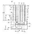
図1〜図3は、本発明の音叉型振動子の第1実施形態を示す図であり、図1は音叉型振動子の平面図、図2は音叉型振動子の側断面図、図3は図1のE−E線矢視断面図である。
Hereinafter, the present invention will be described in more detail with reference to the drawings.
1 to 3 are diagrams showing a first embodiment of a tuning fork vibrator according to the present invention. FIG. 1 is a plan view of the tuning fork vibrator, FIG. 2 is a side sectional view of the tuning fork vibrator, and FIG. FIG. 2 is a cross-sectional view taken along line EE in FIG. 1.
これらの図において符号1は音叉型振動子である。この音叉型振動子1は、3本の弾性腕11、12、13と、これら弾性腕11、12、13のそれぞれの一端側に連結する基部14とを有したもので、弾性腕11、12、13が、隣り合う弾性腕11、12および弾性腕12、13どうしが互い違いになるようにして、該弾性腕11、12、13の表裏方向(上下方向)に振動する、ウォーク型の音叉型振動子である。
In these drawings,
弾性腕11、12、13は、いずれも細長い矩形薄膜状のもので、図1中のZ方向に向く側の面を表面11a、12a、13aとしている。これら弾性腕11、12、13は、その長手方向(図1中のY方向)と直交(交差)する方向(図1中のX方向)に沿って配列されており、図2に示すように前記表面11a(12a、13a)と反対側の裏面11b(12b、13b)側にて、基部14に一体に接続している。
The
基部14は、3本の弾性腕11、12、13のそれぞれの一端側に設けられたもので、本実施形態ではシリコン部分14aと酸化膜部分14bとからなっている。すなわち、底面側の大部分がシリコン部分14aになっており、このシリコン部分14aの上層部分がSiO2からなる酸化膜部分14bになっている。また、酸化膜部分14bは、その上層部分が後述する基材18と同じ層になっており、したがってこの基材18は酸化膜部分14bに連続(接続)したものとなっている。
The
弾性腕11、12、13は、シリコン酸化膜からなる基材18と、該基材18の一方の面側に設けられた圧電素子15、16、17と、を含んで構成されている。
基材18は、本実施形態では温度補正膜としても機能するもので、シリコンの熱酸化膜(シリコン酸化膜)からなるものであり、前記したように基部14の酸化膜部分14bにおける上層部分と同じ層で構成されている。
The
The
この基材18は、弾性腕11、12、13の裏面11b、12b、13b側を構成するものとなっており、したがって前記基部14に接して形成されたものとなっている。また、この基材18は、後述するように基部14を形成するためのシリコンの熱酸化膜によって形成されており、圧電素子15(16、17)の圧電膜の厚さに対応してその厚さが決定され、本実施形態では1.5μm以上2.5μm以下程度の厚さに形成されている。ここで、本実施形態では、この基材18の長さ、すなわち、図2に示すように前記基部14から延出する基材18の長さをAとしている。
The
圧電素子15(16、17)は、基材18及び基部14の一方の面側、すなわち基部14のシリコン部分14aと反対の側に設けられたもので、基材18側から順に下部電極膜15a(16a、17a)、圧電膜15b(16b、17b)、上部電極膜15c(16c、17c)が積層され、形成されたものである。なお、本実施形態においては、図1では図示を省略したが、図2、図3に示すように前記圧電膜15b(16b、17b)と前記上部電極膜15c(16c、17c)との間には、絶縁膜15d(16d、17d)が設けられている。
The piezoelectric element 15 (16, 17) is provided on one surface side of the
下部電極膜15a、16a、17a、および上部電極膜15c、16c、17cは、例えばクロム膜、金膜などの導電体膜からなるもので、厚さ数nm程度に形成されたものである。また、本実施形態では、図1、図2に示すように、下部電極膜15a、16a、17aは前記基材18より僅かに短い長さで形成されているものの、上部電極膜15c、16c、17cは、前記基材18より十分に短い長さで形成されている。したがって、下部電極膜15a、16a、17aと上部電極膜15c、16c、17cとが対向することで形成される電界領域は、基材18の長さに比べて十分に短くなっている。すなわち、前記電界領域の、前記基材18上での前記基部からの長さをCとすると、本実施形態では、前記基材18の長さであるAに対して(1/3)、つまり、C=(1/3)Aとなっている。
The
ここで、本発明においては、この電界領域の長さCの適正な範囲は、以下の式(2)で示される範囲とされる。
(1/4)A≦C≦(1/2)A …式(2)
このような範囲としたのは、電界領域の長さCが基材18の長さ(弾性腕の長さ)Aの(1/4)より短くなると、振動の駆動効率が低下してしまい、十分な振動モードが得られなくなるおそれがあるからである。また、(1/2)より長くなると、弾性腕の先端側まで表裏方向に振動駆動するようになり、設定された本来の振動モードとは別の振動モードが生じるおそれがあるからである。なお、このような範囲においては、特に本実施形態の長さであるC=(1/3)Aとするのが好ましい。
Here, in the present invention, an appropriate range of the length C of the electric field region is a range represented by the following formula (2).
(1/4) A ≦ C ≦ (1/2) A (2)
The reason why such a range is used is that when the length C of the electric field region is shorter than (1/4) of the length of the base material 18 (length of the elastic arm) A, the driving efficiency of vibration is reduced, This is because a sufficient vibration mode may not be obtained. Further, if the length is longer than (1/2), vibration is driven in the front and back directions up to the tip side of the elastic arm, and a vibration mode different from the set original vibration mode may occur. In such a range, it is particularly preferable that C = (1/3) A, which is the length of the present embodiment.
これら電極膜のうち、図1に示すように外側に位置する2つの弾性腕11、13に設けられた各下部電極膜15a、17aと、内側に位置する1つの弾性腕12に設けられた上部電極膜16cとは、後述するように相互に電気的に接続されている。また、外側に位置する2つの弾性腕11、13に設けられた各上部電極膜15c、17cと、内側に位置する1つの弾性腕12に設けられた下部電極膜16aとも、後述するように相互に電気的に接続されている。
Among these electrode films, as shown in FIG. 1, the
圧電膜15b(16b、17b)は、例えばZnO、AlN、PZT(Pb[Zr,Ti]O3)、LiNbO3又はKNbO3から選択された、一種又は複数種の圧電材料からなるもので、本実施形態では、図3に示すように下部電極膜15a(16a、17a)の全体を覆って形成されている。前記圧電材料は、本発明の音叉型振動子の圧電素子に用いられる圧電膜として所望の特性を満たすものとなるので、好適に用いられるが、これら圧電材料の中では、特にZnO、AlNがより良好な温度特性を有し、好ましい。
The
すなわち、薄膜の温度特性に関しては成膜条件によっても特性が変わるが、ZnOの温度特性は約+60ppm/℃であり、AlNの温度特性は約+25ppm/℃である。一方、前記の温度補正膜として機能するシリコン酸化膜(基材18)は、−29ppm/℃〜−40ppm/℃である。したがって、このように負の温度特性を有するシリコン酸化膜(基材18)により、正の温度特性を有する圧電膜15b、16b、17bの温度特性を補正し、これによって音叉振動子1の温度変化による周波数の変動をより少なくすることができる。
That is, the temperature characteristic of the thin film varies depending on the film forming conditions, but the temperature characteristic of ZnO is about +60 ppm / ° C., and the temperature characteristic of AlN is about +25 ppm / ° C. On the other hand, the silicon oxide film (base material 18) functioning as the temperature correction film is −29 ppm / ° C. to −40 ppm / ° C. Accordingly, the temperature characteristics of the
これら圧電膜15b、16b、17bの厚さについては、その温度特性がシリコン酸化膜(基材18)によって補正されることから、前記したようにこの基材18の厚さに対応して決定され、形成されている。具体的には、圧電膜15b、16b、17bをZnOで形成した場合、シリコン酸化膜(SiO2)からなる基材18との膜厚比については、以下の範囲とするのが好ましく、また、AlNで形成した場合、以下の範囲とするのが好ましい。
・圧電膜(ZnO)/基材(SiO2);0.48〜0.67
・圧電膜(AlN)/基材(SiO2);1.16〜1.6
ただし、実際には電極膜なども考慮する必要があるため、以下に示す範囲の膜厚比で圧電膜15b、16b、17b、及び基材18を形成するのが望ましい。
・圧電膜(ZnO)/基材(SiO2);0.4〜1
・圧電膜(AlN)/基材(SiO2);0.7〜1.6
The thicknesses of the
Piezoelectric film (ZnO) / base material (SiO 2 ); 0.48 to 0.67
Piezoelectric film (AlN) / base material (SiO 2 ); 1.16 to 1.6
However, in actuality, since it is necessary to consider an electrode film or the like, it is desirable to form the
Piezoelectric film (ZnO) / base material (SiO 2 ); 0.4-1
Piezoelectric film (AlN) / base material (SiO 2 ); 0.7 to 1.6
また、これら圧電膜15b、16b、17bの長さ、つまり弾性腕11、12、13上での長さは、本実施形態では基材18の長さより僅かに短い長さで形成されている。ここで、圧電膜15b、16b、17bの、前記基材18上での前記基部14からの長さをBとすると、本発明においては、この圧電膜15b、16b、17bの長さBの適正な範囲は、前記基材18の長さであるAに対して、以下の式(1)で示される範囲とされる。
(3/4)A≦B≦A …式(1)
このような範囲としたのは、圧電膜15b、16b、17bによって弾性腕11、12、13に十分な強度を付与するとともに、基本的に基部14に連結する根本側が直接的に振動するようにし、これによってより良好な振動モードを得るためである。
Further, the lengths of the
(3/4) A ≦ B ≦ A (1)
The reason for this range is that the
絶縁膜15d、16d、17dは、圧電膜15b(16b、17b)の全体を覆って設けられたもので、例えばシリコン酸化膜(SiO2)からなっている。これら絶縁膜15d、16d、17dは、圧電膜15b(16d、17d)を保護するとともに、下部電極膜15a(16a、17a)と上部電極膜15c(16c、17c)との短絡を防止する機能を有している。これら絶縁膜15d、16d、17dの膜厚については、短絡防止の観点から50nm以上であるのが好ましく、また、圧電体素子15の特性低下を抑制する観点から500nm以下であるのが好ましい。なお、本発明では、これら絶縁膜15d、16d、17dを省略することもできる。
The insulating
このような構成の圧電素子15、16、17における、各電極膜の接続構造を説明すると、上部電極膜15cと上部電極膜17cとは、図1に示すように接続部21cを介して相互に電気的に接続されている。本実施形態では、これらの上部電極膜15c、17cと接続部21cとは、一体に形成されている。また、下部電極膜16aは、接続部22aおよびプラグ(接続片)23を介して接続部21cと電気的に接続されている。このような構成のもとに、上部電極膜15c、17cと下部電極膜16aとは、電気的に接続されたものとなっている。また、接続部21cには電極パッド24が電気的に接続されており、この電極パッド24を通じて、上部電極膜15c、17cおよび下部電極膜16aに対し、電気信号を供給することができるようになっている。
The connection structure of each electrode film in the
一方、下部電極膜15aと下部電極膜17aとは、接続部21aを介して相互に電気的に接続されている。本実施形態では、これらの下部電極膜15a、17aと接続部21aとは、一体に形成されている。また、上部電極膜16cは、プラグ(接続片)25を介して接続部21aと電気的に接続されている。このような構成のもとに、下部電極膜15a、17aと上部電極膜16cとは、電気的に接続されたものとなっている。また、接続部21aには、電極パッド26が電気的に接続されており、この電極パッド26を通じて、下部電極膜15a、17aおよび上部電極膜16cに対し、電気信号を供給することができるようになっている。なお、前記の接続部21cや接続部22a、電極パッド24、電極パッド25などについては、図2では図示を省略している。
On the other hand, the
基部14は、図2を参照して前述したように、底面側の大部分となるシリコン部分14aと、このシリコン部分14aの上層部分に形成された酸化膜部分14bとからなるものである。酸化膜部分14bは、その上層部分が基材18と同じ層になっており、したがって酸化膜部分14bと基材18とは連続(接続)した同一層となっている。なお、この基部14については、全部がシリコンからなっていてもよく、さらには、シリコン以外の絶縁体、半導電体、導電体のいずれからなっていてもよい。
As described above with reference to FIG. 2, the
また、この基部14は、厚さが100μm〜180μm程度に形成された略直方体状の部位14dと、前記基材18と同じ層からなる基材層14eとからなっている。そして、部位14dにおける、前記弾性腕11、12、13に連結する側の端面14cが、前記基材18および基材層14eに対して傾斜する傾斜面(テーパ面)になっている。この傾斜面(端面14c)は、その傾斜角θが、75°以上90°未満になっている。このような構成によって基部14における部位14dは、弾性腕11、12、13を振動させた際に基部14からの振動もれを抑え、また、応力分散を起こさせるようになっている。よって、本実施形態の音叉型振動子1では、Q値が上がることが期待できる。
Further, the
このような音叉型振動子1を製造するには、まず、図4(a)に示すようにシリコン基板(シリコンウエハ)30を用意する。そして、熱酸化法によってその表面を熱酸化し、図4(b)に示すように熱酸化膜(シリコン酸化膜)31を形成する。
続いて、前記熱酸化膜31上に下部電極層(図示せず)を形成し、さらにこれをエッチングによってパターニングすることにより、図2、図3にしたように下部電極膜15a、16a、17aを形成する。その際、弾性腕11、12、13を形成する前記基材18上では、図2に示したように、該基材18より僅かに短い長さで下部電極膜15a、16a、17aを形成する。
In order to manufacture such a
Subsequently, a lower electrode layer (not shown) is formed on the
次に、下部電極膜15a、16a、17aを覆って圧電層(図示せず)を形成し、さらにこれをエッチングによってパターニングすることにより、図2、図3にしたように下部電極膜15a、16a、17aを覆った状態に圧電膜15b、16b、17bを形成する。その際、これら圧電膜15b、16b、17bについても、前記基材18上では、図2に示したように、前記基材18より僅かに短い長さで圧電膜15b、16b、17bを形成する。
Next, a piezoelectric layer (not shown) is formed so as to cover the
次いで、圧電膜15b、16b、17bを覆って絶縁層(図示せず)を形成し、さらにこれをエッチングによってパターニングすることにより、図2、図3にしたように圧電膜15b、16b、17bを覆った状態に絶縁膜15d、16d、17dを形成する。
Next, an insulating layer (not shown) is formed so as to cover the
次いで、絶縁膜15d、16d、17dを覆って上部電極層(図示せず)を形成し、さらにこれをエッチングによってパターニングすることにより、図2、図3にしたように絶縁膜15d、16d、17d上に上部電極膜15c、16c、17cを形成する。その際、前記基材18上では、図2に示したように該基材18より十分に短い長さ、本実施形態では該基材18の長さであるAに対して(1/3)、つまり、(1/3)Aの長さで上部電極膜15c、16c、17cを形成する。このような長さで上部電極膜15c、16c、17cを形成することにより、下部電極膜15a、16a、17aと上部電極膜15c、16c、17cとが対向することで形成される電界領域の、前記基材18上での前記基部14からの長さCは、上部電極膜15c、16c、17cの基材18上での長さである、(1/3)Aとなる。
Next, an upper electrode layer (not shown) is formed so as to cover the insulating
これにより、図4(c)に示すように熱酸化膜31上に圧電素子15、16、17を形成する。
なお、前記の下部電極層のパターニングや上部電極層のパターニングなどの際に、図1に示した接続部21cや接続部22a、電極パッド24、電極パッド25なども形成しておく。
Thus, the
In the patterning of the lower electrode layer and the upper electrode layer, the
次いで、前記シリコン基板30とその熱酸化膜31の一部をドライエッチングによってパターニングし、図4(d)に示すようにシリコン部分14aと酸化膜部分14bとからなる基部14を形成する。このとき、エッチング条件を適宜に設定することにより、基部14における前記部位14dの一方の端面14cを傾斜面(テーパ面)に形成する。
その後、前記熱酸化膜31の残った部分をドライエッチングによってパターニングすることにより、基材18を形成し、弾性腕11、12、13を形成する。
これにより、図1〜図3に示した音叉型振動子1が得られる。
Next, the
Thereafter, the remaining portion of the
As a result, the
このようにして得られた本実施形態の音叉型振動子1は、前記の電極パッド24および電極パッド26に電気信号を供給することにより、弾性腕11、13と弾性腕12とを互い違いに上下振動、すなわちその表裏方向に振動させることができる。具体的には、各上部電極膜15c、16c、17cと下部電極膜15a、16a、17aとの間に電圧を印加した際に、外側の各圧電体素子15、17にかかる電界の方向と内側の圧電体素子16にかかる電界の方向とが逆向きになる。したがって、音叉型振動子1の斜視図である図5において矢印で示すように、弾性腕11、13の振動方向と弾性腕12の振動方向とが逆向きになり、電界印加により弾性腕11、13と弾性腕12とが互い違いに上下運動を行う。
The
このような音叉型振動子1によれば、3脚(3本)構造としたことにより、上下振動(図5中のZ方向に沿った表裏方向の振動)を用いる振動モードにおいてQ値を高めることができる。
また、C=(1/3)Aとしたことで、(1/4)A≦C≦(1/2)Aとする式(2)を満足させているので、弾性腕11、12、13を、基部14に連結する根本側のみに電界を与えて振動駆動させ、先端側については根本側の振動に追従させることができる。したがって、弾性腕11、12、13にうねりなどが生じるのを防止し、設定された本来の振動モードのみを生じさせることができ、これによってより良好な振動モードを得ることができる。
さらに、(3/4)A≦B≦Aとする式(1)を満足させているので、圧電膜15b、16b、17bによって弾性腕11、12、13に十分な強度を付与するとともに、基本的に基部14に連結する根本側を直接的に振動させるようになり、したがって、より良好な振動モードを得ることができる。
According to the tuning
Further, since C = (1/3) A is satisfied, Expression (2) satisfying (1/4) A ≦ C ≦ (1/2) A is satisfied, so that the
Furthermore, since the expression (1) satisfying (3/4) A ≦ B ≦ A is satisfied, the
また、各弾性腕11、12、13が、負の温度特性を有するシリコン酸化膜からなる基材18を有しているので、圧電素子15、16、17中の正の温度特性を有する圧電膜15b、16b、17bの温度特性を補正することができる。したがって、この音叉型振動子1は温度変化による周波数の変動が少ない優れたものとなる。
さらに、シリコン酸化膜は膜形成性に優れ、特に良好な厚さ精度が得られるので、このシリコン酸化膜によって基材18を形成することにより、音叉型振動子は加工性にも優れたものとなる。特に、シリコン基板の一部を熱酸化し、さらにこれらシリコンやシリコン酸化膜をパターニングすることで基部14や基材18を形成することにより、これら基部14や基材18の形成を容易にすることができるとともに、基部14と基材18との間の接合強度を十分に高めることができる。
Moreover, since each
Furthermore, since the silicon oxide film has excellent film formability and particularly good thickness accuracy can be obtained, the tuning fork vibrator is also excellent in workability by forming the
図6、図7は本発明の音叉型振動子の第2実施形態を示す図であり、図6は音叉型振動子の平面図、図7は音叉型振動子の側断面図である。図6、図7に示した音叉型振動子40が図1、図2に示した前記実施形態と異なるところは、下部電極膜15a、16a、17aと上部電極膜15c、16c、17cとのうち、下部電極膜15a、16a、17aの方を前記基材18より十分に短い長さで形成するのに代えて、上部電極膜15c、16c、17cの方を十分に短い長さに形成した点である。
FIGS. 6 and 7 are views showing a second embodiment of the tuning fork vibrator according to the present invention, FIG. 6 is a plan view of the tuning fork vibrator, and FIG. 7 is a side sectional view of the tuning fork vibrator. The
すなわち、本実施形態では、上部電極膜15c、16c、17cを前記基材18より僅かに短い長さで形成しているものの、下部電極膜15a、16a、17aについては、前記基材18より十分に短い長さに形成している。具体的には、基材18の長さをAとし、該基材18上での前記基部14からの下部電極膜15a、16a、17aの長さをCとすると、このCの長さを、Aの(1/3)、つまり(1/3)Aの長さにしている。
That is, in this embodiment, although the
したがって、下部電極膜15a、16a、17aと上部電極膜15c、16c、17cとが対向することで形成される電界領域は、該電界領域の、前記基材18上での前記基部14からの長さをCとすると、前記第1実施形態と同様に本第2実施形態においても、前記基材18の長さであるAに対して(1/3)、つまり、C=(1/3)Aとなる。
なお、音叉型振動子40の各要素の構成材料、形状、膜厚等の好適な例については、前記第1実施形態と同様であり、ここでは説明を省略する。
Therefore, the electric field region formed by the
Note that suitable examples of the constituent material, shape, film thickness, and the like of each element of the
このような音叉型振動子40にあっても、特にC=(1/3)Aとしたことで、(1/4)A≦C≦(1/2)Aとする式(2)を満足させているので、弾性腕11、12、13を、基部14に連結する根本側のみに電界を与えて振動駆動させ、先端側については根本側の振動に追従させることができる。よって、弾性腕11、12、13にうねりなどが生じるのを防止し、設定された本来の振動モードのみを生じさせることができ、これによってより良好な振動モードを得ることができる。
さらに、(3/4)A≦B≦Aとする式(1)を満足させているので、圧電膜15b、16b、17bによって弾性腕11、12、13に十分な強度を付与するとともに、基本的に基部14に連結する根本側を直接的に振動させるようになり、したがって、より良好な振動モードを得ることができる。
また、各弾性腕11、12、13が、負の温度特性を有するシリコン酸化膜からなる基材18を有しているので、圧電素子15、16、17中の正の温度特性を有する圧電膜15b、16b、17bの温度特性を補正することができる。したがって、この音叉型振動子1は温度変化による周波数の変動が少ない優れたものとなる。
Even in such a tuning
Furthermore, since the expression (1) satisfying (3/4) A ≦ B ≦ A is satisfied, the
Moreover, since each
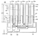
図8、図9は音叉型振動子の第3実施形態を示す図であり、図8は音叉型振動子の平面図、図9は、図8のF−F線矢視線断面図である。図8、図9に示した音叉型振動子100が図1に示した前記実施形態と異なるところは、弾性腕が3本でなく、5本備えた点である。すなわち、この音叉型振動子100は、5本の弾性腕111、112、113、114、115と、これら弾性腕111、112、113、114、115のそれぞれの一端側に連結する基部121とを有したもので、弾性腕111、112、113、114、115が、隣り合う弾性腕どうしが互い違いになるようにして、該弾性腕111、112、113、114、115の表裏方向(上下方向)に振動する、ウォーク型の音叉型振動子である。
8 and 9 are views showing a third embodiment of the tuning fork vibrator, FIG. 8 is a plan view of the tuning fork vibrator, and FIG. 9 is a cross-sectional view taken along line FF in FIG. The
弾性腕111、112、113、114、115は、いずれも細長い矩形薄膜状のもので、その長手方向(図8中のY方向)と直交(交差)する方向(図8中のX方向)に沿って配列されており、図8に示すように基部121に一体に接続している。
これら弾性腕111、112、113、114、115は、前記音叉型振動子1の弾性腕11、12、13と同様に、シリコン酸化膜からなる基材135と、該基材135の一方の面側に設けられた圧電素子116、117、118、119、120と、を含んで構成されている。
Each of the
These
基材135は、前記基材18と同様に、温度補正膜としても機能するもので、シリコンの熱酸化膜(シリコン酸化膜)からなっている。
圧電素子116、117、118、119、120は、図9に示すように基材135の一方の面側、すなわち基部121と反対の側に設けられたもので、基材135側から順に下部電極膜116a、117a、118a、119a、120a、圧電膜116b、117b、118b、119b、120b、上部電極膜116c、117c、118c、119c、120c、が積層され、形成されたものである。なお、本実施形態では、絶縁膜について省略しているが、前記圧電膜116b(117b、118b、119b、120b)と前記上部電極膜116c(117c、118c、119c、120c)との間に、前記実施形態と同様にして絶縁膜を設けてもよい。
The
The
また、圧電素子116、117、118、119、120における、上部電極膜116c、117c、118c、119c、120cは、前記第1実施形態における上部電極膜15c、16c、17cと同様に、基材135の長さをAとし、該基材135上での前記基部121からの上部電極膜116c、117c、118c、119c、120cの長さをCとすると、このCの長さは、Aの(1/3)、つまり(1/3)Aの長さになっている。
The
したがって、下部電極膜116a、117a、118a、119a、120aと上部電極膜116c、117c、118c、119c、120cとが対向することで形成される電界領域は、該電界領域の、前記基材135上での前記基部121からの長さをCとすると、前記第1実施形態と同様に、本第3実施形態においても、前記基材135の長さであるAに対して(1/3)、つまり、C=(1/3)Aとなる。
なお、音叉型振動子100の各要素の構成材料、形状、膜厚等の好適な例については、前記実施形態と同様であり、ここでは説明を省略する。
Therefore, the electric field region formed by the
Note that suitable examples of the constituent material, shape, film thickness, and the like of each element of the
このような音叉型振動子100にあっても、特にC=(1/3)Aとしたことで、(1/4)A≦C≦(1/2)Aとする式(2)を満足させているので、弾性腕111、112、113、114、115を、基部121に連結する根本側のみに電界を与えて振動駆動させ、先端側については根本側の振動に追従させることができる。よって、弾性腕111、112、113、114、115にうねりなどが生じるのを防止し、設定された本来の振動モードのみを生じさせることができ、これによってより良好な振動モードを得ることができる。
さらに、(3/4)A≦B≦Aとする式(1)を満足させているので、圧電膜116b、117b、118b、119b、120bによって弾性腕111、112、113、114、115に十分な強度を付与するとともに、基本的に基部121に連結する根本側を直接的に振動させるようになり、したがって、より良好な振動モードを得ることができる。
Even in such a tuning
Furthermore, since the expression (1) satisfying (3/4) A ≦ B ≦ A is satisfied, the
また、弾性腕を5脚(5本)構造としたことにより、上下振動(表裏方向の振動)を用いる振動モードにおいてQ値を高めることができる。
また、各弾性腕111、112、113、114、115が、負の温度特性を有するシリコン酸化膜からなる基材135を有しているので、圧電素子116、117、118、119、120中の正の温度特性を有する圧電膜116b、117b、118b、119b、120bの温度特性を補正することができる。したがって、この音叉型振動子100も温度変化による周波数の変動が少ない優れたものとなる。
Further, since the elastic arm has a five-leg (five) structure, the Q value can be increased in a vibration mode using vertical vibration (front-back vibration).
Further, since each
なお、本実施形態の弾性腕を5本備えた構造においても、前記第2実施形態の場合と同様に、下部電極膜116a、117a、118a、119a、120aの長さを、例えば基材135の長さAの(1/3)にし、前記式(2)を満足させるように構成してもよい。
Even in the structure having five elastic arms of this embodiment, the length of the
次に、本発明の発振器について説明する。本発明の発振器は、図10に示すように、前記音叉型振動子1(又は音叉型振動子40、100)を含んで構成されたものである。
すなわち、この発振器は、音叉型振動子1と、この音叉型振動子1と並列に接続されたインバータ2と、を含んで構成されている。インバータ2の一方端が前記電極パッド24に接続され、他方端が前記電極パッド26に接続されている。また、図示のように、音叉型振動子1とインバータ2との一方の接続点と接地端との間に接続された容量素子(コンデンサ)3と、音叉型振動子1とインバータ2との他方の接続点と接地端との間に接続された容量素子(コンデンサ)4と、をさらに備えて構成されている。
Next, the oscillator of the present invention will be described. As shown in FIG. 10, the oscillator according to the present invention includes the tuning fork vibrator 1 (or the
That is, the oscillator includes a tuning
このような発振器にあっては、前述したようにより良好な振動モードが得られ、さらに温度変化による周波数の変動の少ない音叉型振動子1を含んでなるので、発振器自体の性能が向上し、さらに温度変化による周波数の変動が少ない優れたものとなる。
In such an oscillator, a better vibration mode can be obtained as described above, and the
なお、本発明は前記実施形態に限定されることなく、本発明の要旨を逸脱しない範囲で種々の変更が可能である。例えば、前記実施形態では、奇数個の弾性腕として3本あるいは5本の例を示したが、弾性腕の本数については、さらに多くの奇数個(7本、9本…)を有するように構成するようにしてもよい。
また、前記実施形態では基材をシリコンの熱酸化で形成したが、例えばCVD法で形成したシリコン酸化膜で基材を形成してもよい。
The present invention is not limited to the above-described embodiment, and various modifications can be made without departing from the gist of the present invention. For example, in the above-described embodiment, three or five examples are shown as the odd number of elastic arms, but the number of elastic arms is configured to have a larger number of odd numbers (7, 9,...). You may make it do.
Moreover, in the said embodiment, although the base material was formed by thermal oxidation of silicon, you may form a base material with the silicon oxide film formed, for example by CVD method.
さらに、前記実施形態では基材をシリコン酸化膜で形成したが、例えば基材や基部を水晶で形成してもよい。その場合にも、水晶によって圧電素子中の圧電膜等の温度特性を補正し、これによって温度変化による特性変動の少ない振動子を形成することができる。なお、基材を水晶で形成する場合、水晶としてXカット板を用いるのが好ましい。Xカット板を用いることにより、小型化に伴う温度特性の低下を抑制し、温度特性を良好にする効果をさらに高めることができる。また、弾性腕や基部のエッチングによる形状加工が容易になる。ただし、水晶としてはATカット板やZカット板を用いることもできる。 Furthermore, in the said embodiment, although the base material was formed with the silicon oxide film, you may form a base material and a base part with a quartz crystal, for example. Even in such a case, it is possible to correct the temperature characteristics of the piezoelectric film or the like in the piezoelectric element by using the quartz crystal, thereby forming a vibrator with less characteristic fluctuation due to temperature change. In addition, when forming a base material with a crystal | crystallization, it is preferable to use an X cut board as a crystal | crystallization. By using the X-cut plate, it is possible to further suppress the decrease in temperature characteristics due to downsizing and further improve the effect of improving the temperature characteristics. Further, shape processing by etching of the elastic arm and the base becomes easy. However, an AT cut plate or a Z cut plate can be used as the crystal.
1、40、100…音叉型振動子、2…インバータ、3、4…容量素子、11、12、13…弾性腕、11a、12a、13a…表面、11b、12b、13b…裏面、14…基部、15、16、17…圧電素子、15a、16a、17a…下部電極膜、15b、16b、17b…圧電膜、15c、16c、17c…上部電極膜、15d、16d、17d…絶縁膜、18…基材、21a、21c、22a…接続部、24、26…電極パッド、111、112、113、114、115…弾性腕、116、117、118、119、120…圧電素子、116a、117a、118a、119a、120a…下部電極膜、116b、117b、118b、119b、120b…圧電膜、116c、117c、118c、119c、120c…上部電極膜、121…基部、135…基材
DESCRIPTION OF
Claims (8)
前記弾性腕は、前記弾性腕の主面に、下部電極膜および上部電極膜の間に圧電膜を配置した圧電素子が設けられ、
前記弾性腕の前記一端から他端までの長さをAとし、前記弾性腕上の前記圧電膜の長さをBとし、前記弾性腕上の前記下部電極膜と前記上部電極膜とが平面視で重複する部分の長さをCとすると、以下の式(1)、式(2)
(3/4)A≦B≦A …式(1)
(1/4)A≦C≦(1/2)A …式(2)
を共に満足することを特徴とする振動子。 3 and the elastic arm of the above odd number, has a base portion for connecting one end of each of said resilient arms, the resilient arms, the resilient arm adjacent to each other vibrate in the front-back direction of the alternately the elastic arm A vibrator,
The elastic arm is provided with a piezoelectric element in which a piezoelectric film is disposed between a lower electrode film and an upper electrode film on a main surface of the elastic arm ,
The length from the one end to the other end of the elastic arm is A, the length of the piezoelectric film on the elastic arm is B, and the lower electrode film and the upper electrode film on the elastic arm are viewed in plan view. If the length of the overlapping part is C, the following formulas (1) and (2)
(3/4) A ≦ B ≦ A (1)
(1/4) A ≦ C ≦ (1/2) A (2)
A vibrator characterized by satisfying both.
且つ、前記基部の主面側はシリコン酸化膜を含み、前記基部の主面と反対の面側はシリコンを含むことを特徴とする請求項2記載の振動子。 In the base, the main surface of the base and the main surface of the elastic arm are in the same plane,
3. The vibrator according to claim 2, wherein a main surface side of the base portion includes a silicon oxide film, and a surface side opposite to the main surface of the base portion includes silicon .
前記振動子に接続されたインバータと、を含むことを特徴とする発振器。And an inverter connected to the vibrator.
Priority Applications (1)
| Application Number | Priority Date | Filing Date | Title |
|---|---|---|---|
| JP2008188663A JP5168002B2 (en) | 2008-07-22 | 2008-07-22 | Vibrator and oscillator |
Applications Claiming Priority (1)
| Application Number | Priority Date | Filing Date | Title |
|---|---|---|---|
| JP2008188663A JP5168002B2 (en) | 2008-07-22 | 2008-07-22 | Vibrator and oscillator |
Publications (3)
| Publication Number | Publication Date |
|---|---|
| JP2010028536A JP2010028536A (en) | 2010-02-04 |
| JP2010028536A5 JP2010028536A5 (en) | 2011-09-01 |
| JP5168002B2 true JP5168002B2 (en) | 2013-03-21 |
Family
ID=41733925
Family Applications (1)
| Application Number | Title | Priority Date | Filing Date |
|---|---|---|---|
| JP2008188663A Expired - Fee Related JP5168002B2 (en) | 2008-07-22 | 2008-07-22 | Vibrator and oscillator |
Country Status (1)
| Country | Link |
|---|---|
| JP (1) | JP5168002B2 (en) |
Cited By (1)
| Publication number | Priority date | Publication date | Assignee | Title |
|---|---|---|---|---|
| US10756670B2 (en) | 2016-12-19 | 2020-08-25 | Seiko Epson Corporation | Resonator, oscillator, electronic apparatus, and vehicle |
Families Citing this family (15)
| Publication number | Priority date | Publication date | Assignee | Title |
|---|---|---|---|---|
| JP2011199453A (en) * | 2010-03-18 | 2011-10-06 | Seiko Epson Corp | Vibrator, and vibrating device |
| JP5552878B2 (en) * | 2010-04-14 | 2014-07-16 | セイコーエプソン株式会社 | Vibrating piece, vibrating device and electronic device |
| JP5533349B2 (en) * | 2010-06-30 | 2014-06-25 | セイコーエプソン株式会社 | Bending vibrator, bending vibrator, oscillator, and electronic device |
| JP5581931B2 (en) * | 2010-09-17 | 2014-09-03 | セイコーエプソン株式会社 | Vibrating piece, manufacturing method of vibrating piece, vibrator, vibrating device, and electronic apparatus |
| JP2012147347A (en) * | 2011-01-14 | 2012-08-02 | Seiko Epson Corp | Vibration piece, vibrator, oscillator and electronic apparatus |
| JP2013062643A (en) * | 2011-09-13 | 2013-04-04 | Seiko Epson Corp | Vibration piece, vibrator, oscillator, and electronic apparatus |
| JP5685962B2 (en) | 2011-02-02 | 2015-03-18 | セイコーエプソン株式会社 | Vibrating piece, vibrator, oscillator and electronic device |
| CN102629861A (en) | 2011-02-02 | 2012-08-08 | 精工爱普生株式会社 | Vibrator element, vibrator, oscillator, and electronic apparatus |
| JP5923862B2 (en) * | 2011-03-18 | 2016-05-25 | セイコーエプソン株式会社 | Vibrating piece, vibrator, oscillator and electronic device |
| JP5942582B2 (en) * | 2012-05-15 | 2016-06-29 | セイコーエプソン株式会社 | Method for manufacturing vibrator |
| JP6094672B2 (en) * | 2013-05-13 | 2017-03-15 | 株式会社村田製作所 | Vibration device |
| JP6482169B2 (en) | 2013-07-19 | 2019-03-13 | セイコーエプソン株式会社 | Vibrating piece, vibrator, oscillator, electronic device and moving object |
| JP6395008B2 (en) | 2014-12-26 | 2018-09-26 | 株式会社村田製作所 | Manufacturing method of resonator |
| JP6836180B2 (en) * | 2017-05-30 | 2021-02-24 | セイコーエプソン株式会社 | MEMS elements, electronics and mobiles |
| JP2017216753A (en) * | 2017-09-15 | 2017-12-07 | セイコーエプソン株式会社 | Vibration piece, vibrator, electronic device, electronic apparatus, and movable body |
Family Cites Families (6)
| Publication number | Priority date | Publication date | Assignee | Title |
|---|---|---|---|---|
| JPS57199312A (en) * | 1981-06-02 | 1982-12-07 | Citizen Watch Co Ltd | Piezoelectric oscillator |
| JPH0783671A (en) * | 1993-07-22 | 1995-03-28 | Yoshiro Tomikawa | Vibration-type gyroscope |
| JPH085382A (en) * | 1994-06-23 | 1996-01-12 | Nippondenso Co Ltd | Angular-velocity sensor |
| JP3322153B2 (en) * | 1997-03-07 | 2002-09-09 | セイコーエプソン株式会社 | Tuning fork type crystal vibrating piece |
| JP3972790B2 (en) * | 2001-11-27 | 2007-09-05 | 松下電器産業株式会社 | Thin film micromechanical resonator and thin film micromechanical resonator gyro |
| JP4404218B2 (en) * | 2006-03-29 | 2010-01-27 | セイコーエプソン株式会社 | Tuning fork vibrator and manufacturing method thereof |
-
2008
- 2008-07-22 JP JP2008188663A patent/JP5168002B2/en not_active Expired - Fee Related
Cited By (1)
| Publication number | Priority date | Publication date | Assignee | Title |
|---|---|---|---|---|
| US10756670B2 (en) | 2016-12-19 | 2020-08-25 | Seiko Epson Corporation | Resonator, oscillator, electronic apparatus, and vehicle |
Also Published As
| Publication number | Publication date |
|---|---|
| JP2010028536A (en) | 2010-02-04 |
Similar Documents
| Publication | Publication Date | Title |
|---|---|---|
| JP5168002B2 (en) | Vibrator and oscillator | |
| JP5067033B2 (en) | Tuning fork type oscillator, oscillator | |
| US8310137B2 (en) | Resonator element and resonator | |
| JP4715652B2 (en) | Piezoelectric vibrating piece | |
| JP5067035B2 (en) | Tuning fork type oscillator, oscillator | |
| JPWO2007088696A1 (en) | Piezoelectric vibration device | |
| JP2010252302A (en) | Bending vibrator piece and oscillator using the same | |
| JP5067034B2 (en) | Tuning fork type oscillator, oscillator | |
| JP5233466B2 (en) | Vibrator, oscillator, and method for producing the vibrator | |
| WO2010047115A1 (en) | Bending vibration piece, bending vibrator, and piezoelectric device | |
| JP5375503B2 (en) | Bending vibration piece | |
| WO2008059781A1 (en) | Electronic component and method for manufacturing the same | |
| JP6719313B2 (en) | Piezoelectric resonator element and piezoelectric vibrator | |
| JP3953017B2 (en) | Piezoelectric vibrator for vibration gyro | |
| US20210343929A1 (en) | Piezoelectric device | |
| JP2009111623A (en) | Piezoelectric vibrating device | |
| US9331668B2 (en) | Vibrator with a beam-shaped portion above a recess in a substrate, and oscillator using same | |
| WO2020136994A1 (en) | Piezoelectric transducer | |
| JP2009100076A (en) | Piezoelectric vibrating reed | |
| JP6232957B2 (en) | Piezoelectric acceleration sensor | |
| JP2010206821A (en) | Piezoelectric vibration piece | |
| WO2019188381A1 (en) | Vibration element | |
| JP6064342B2 (en) | Vibrating piece and electronic equipment | |
| JP7076692B2 (en) | Vibration element and oscillator equipped with it | |
| WO2019188078A1 (en) | Vibration element |
Legal Events
| Date | Code | Title | Description |
|---|---|---|---|
| A521 | Request for written amendment filed |
Free format text: JAPANESE INTERMEDIATE CODE: A523 Effective date: 20110706 |
|
| A621 | Written request for application examination |
Free format text: JAPANESE INTERMEDIATE CODE: A621 Effective date: 20110706 |
|
| A521 | Request for written amendment filed |
Free format text: JAPANESE INTERMEDIATE CODE: A821 Effective date: 20110708 |
|
| RD04 | Notification of resignation of power of attorney |
Free format text: JAPANESE INTERMEDIATE CODE: A7424 Effective date: 20120125 |
|
| A977 | Report on retrieval |
Free format text: JAPANESE INTERMEDIATE CODE: A971007 Effective date: 20121114 |
|
| A01 | Written decision to grant a patent or to grant a registration (utility model) |
Free format text: JAPANESE INTERMEDIATE CODE: A01 Effective date: 20121127 |
|
| A61 | First payment of annual fees (during grant procedure) |
Free format text: JAPANESE INTERMEDIATE CODE: A61 Effective date: 20121210 |
|
| LAPS | Cancellation because of no payment of annual fees |