JP5166074B2 - Semiconductor memory device, control method thereof, and error correction system - Google Patents
Semiconductor memory device, control method thereof, and error correction system Download PDFInfo
- Publication number
- JP5166074B2 JP5166074B2 JP2008051419A JP2008051419A JP5166074B2 JP 5166074 B2 JP5166074 B2 JP 5166074B2 JP 2008051419 A JP2008051419 A JP 2008051419A JP 2008051419 A JP2008051419 A JP 2008051419A JP 5166074 B2 JP5166074 B2 JP 5166074B2
- Authority
- JP
- Japan
- Prior art keywords
- error
- error correction
- data
- code
- correction
- Prior art date
- Legal status (The legal status is an assumption and is not a legal conclusion. Google has not performed a legal analysis and makes no representation as to the accuracy of the status listed.)
- Expired - Fee Related
Links
- 238000012937 correction Methods 0.000 title claims abstract description 399
- 239000004065 semiconductor Substances 0.000 title claims abstract description 38
- 238000000034 method Methods 0.000 title claims abstract description 11
- 238000001514 detection method Methods 0.000 claims description 119
- 230000015654 memory Effects 0.000 claims description 74
- 239000011159 matrix material Substances 0.000 claims description 7
- 239000007787 solid Substances 0.000 abstract description 3
- 238000010586 diagram Methods 0.000 description 30
- 238000012545 processing Methods 0.000 description 11
- 101100539386 Caenorhabditis elegans uda-1 gene Proteins 0.000 description 5
- 238000012546 transfer Methods 0.000 description 5
- 206010009944 Colon cancer Diseases 0.000 description 4
- 238000004519 manufacturing process Methods 0.000 description 4
- 230000006870 function Effects 0.000 description 3
- 238000007667 floating Methods 0.000 description 2
- 239000000758 substrate Substances 0.000 description 2
- 230000005540 biological transmission Effects 0.000 description 1
- 238000004891 communication Methods 0.000 description 1
- 239000000470 constituent Substances 0.000 description 1
- 125000004122 cyclic group Chemical group 0.000 description 1
- 230000002950 deficient Effects 0.000 description 1
- 238000009792 diffusion process Methods 0.000 description 1
- 238000005516 engineering process Methods 0.000 description 1
- 230000005669 field effect Effects 0.000 description 1
- 229910044991 metal oxide Inorganic materials 0.000 description 1
- 150000004706 metal oxides Chemical class 0.000 description 1
Images


Classifications
-
- G—PHYSICS
- G06—COMPUTING; CALCULATING OR COUNTING
- G06F—ELECTRIC DIGITAL DATA PROCESSING
- G06F11/00—Error detection; Error correction; Monitoring
- G06F11/07—Responding to the occurrence of a fault, e.g. fault tolerance
- G06F11/08—Error detection or correction by redundancy in data representation, e.g. by using checking codes
- G06F11/10—Adding special bits or symbols to the coded information, e.g. parity check, casting out 9's or 11's
- G06F11/1008—Adding special bits or symbols to the coded information, e.g. parity check, casting out 9's or 11's in individual solid state devices
- G06F11/1012—Adding special bits or symbols to the coded information, e.g. parity check, casting out 9's or 11's in individual solid state devices using codes or arrangements adapted for a specific type of error
-
- G—PHYSICS
- G06—COMPUTING; CALCULATING OR COUNTING
- G06F—ELECTRIC DIGITAL DATA PROCESSING
- G06F11/00—Error detection; Error correction; Monitoring
- G06F11/07—Responding to the occurrence of a fault, e.g. fault tolerance
- G06F11/08—Error detection or correction by redundancy in data representation, e.g. by using checking codes
- G06F11/10—Adding special bits or symbols to the coded information, e.g. parity check, casting out 9's or 11's
- G06F11/1008—Adding special bits or symbols to the coded information, e.g. parity check, casting out 9's or 11's in individual solid state devices
- G06F11/1072—Adding special bits or symbols to the coded information, e.g. parity check, casting out 9's or 11's in individual solid state devices in multilevel memories
-
- H—ELECTRICITY
- H03—ELECTRONIC CIRCUITRY
- H03M—CODING; DECODING; CODE CONVERSION IN GENERAL
- H03M13/00—Coding, decoding or code conversion, for error detection or error correction; Coding theory basic assumptions; Coding bounds; Error probability evaluation methods; Channel models; Simulation or testing of codes
- H03M13/29—Coding, decoding or code conversion, for error detection or error correction; Coding theory basic assumptions; Coding bounds; Error probability evaluation methods; Channel models; Simulation or testing of codes combining two or more codes or code structures, e.g. product codes, generalised product codes, concatenated codes, inner and outer codes
- H03M13/2906—Coding, decoding or code conversion, for error detection or error correction; Coding theory basic assumptions; Coding bounds; Error probability evaluation methods; Channel models; Simulation or testing of codes combining two or more codes or code structures, e.g. product codes, generalised product codes, concatenated codes, inner and outer codes using block codes
-
- G—PHYSICS
- G06—COMPUTING; CALCULATING OR COUNTING
- G06F—ELECTRIC DIGITAL DATA PROCESSING
- G06F11/00—Error detection; Error correction; Monitoring
- G06F11/07—Responding to the occurrence of a fault, e.g. fault tolerance
- G06F11/08—Error detection or correction by redundancy in data representation, e.g. by using checking codes
- G06F11/10—Adding special bits or symbols to the coded information, e.g. parity check, casting out 9's or 11's
- G06F11/1008—Adding special bits or symbols to the coded information, e.g. parity check, casting out 9's or 11's in individual solid state devices
- G06F11/1044—Adding special bits or symbols to the coded information, e.g. parity check, casting out 9's or 11's in individual solid state devices with specific ECC/EDC distribution
-
- G—PHYSICS
- G11—INFORMATION STORAGE
- G11C—STATIC STORES
- G11C16/00—Erasable programmable read-only memories
- G11C16/02—Erasable programmable read-only memories electrically programmable
- G11C16/04—Erasable programmable read-only memories electrically programmable using variable threshold transistors, e.g. FAMOS
- G11C16/0483—Erasable programmable read-only memories electrically programmable using variable threshold transistors, e.g. FAMOS comprising cells having several storage transistors connected in series
-
- G—PHYSICS
- G11—INFORMATION STORAGE
- G11C—STATIC STORES
- G11C29/00—Checking stores for correct operation ; Subsequent repair; Testing stores during standby or offline operation
- G11C29/04—Detection or location of defective memory elements, e.g. cell constructio details, timing of test signals
- G11C2029/0411—Online error correction
Abstract
Description
本発明は、半導体記憶装置、その制御方法、および誤り訂正システムに関し、詳細には、不揮発に情報を記憶する半導体メモリの誤りを訂正する誤り訂正回路を備えた半導体記憶装置、その制御方法、および誤り訂正システムに関する。 The present invention relates to a semiconductor memory device, a control method thereof, and an error correction system, and more specifically, a semiconductor memory device including an error correction circuit for correcting an error of a semiconductor memory that stores information in a nonvolatile manner, a control method thereof, and It relates to an error correction system.
近年、保持された電荷量に応じて情報を記憶するフラッシュメモリなどの半導体素子が広く知られている。また、電荷量の閾値を複数設定することにより2ビット以上の情報を記憶する多値メモリ技術も開発されている。 In recent years, semiconductor devices such as flash memories that store information in accordance with the amount of charge held are widely known. In addition, a multi-level memory technology for storing information of 2 bits or more by setting a plurality of charge amount thresholds has been developed.
このような半導体メモリ素子では、時間経過の増大とともに電荷が放電されていくため、閾値を超えて電荷が放電されると情報の読み出し時に誤りが発生する。特に、多値型のメモリ素子では一般に閾値の間隔が狭いため、誤りが発生する可能性が高くなる。 In such a semiconductor memory device, since charges are discharged as time elapses, an error occurs when information is read if the charges are discharged beyond the threshold. In particular, in a multi-level memory element, since the threshold interval is generally narrow, there is a high possibility that an error will occur.
上記のような半導体メモリ素子を用いた記憶装置では、誤った情報を正しく復元するための誤り訂正機構が設けられていることがある(例えば、特許文献1参照)。 In a storage device using the semiconductor memory element as described above, an error correction mechanism for correctly restoring erroneous information may be provided (for example, see Patent Document 1).
一般に、複数のビットからなるデータに、情報の記録から時間が経過したこと等を理由
として誤りが多く含まれている場合でも誤りを訂正するには、高い誤り訂正能力を有する
訂正機構が必要である。高い誤り訂正能力を有する訂正機構は、回路規模が大きく、消費
電力が大きく、処理に時間を要する。通常、情報の記憶から長時間が経過した後でも正し
い情報を復元できることを保証しておくために、高い誤り訂正能力を有する訂正機構が設
けられている。そして、情報の記憶からの時間の経過の長短によらずに、一律に、高性能
の誤り訂正機構が適用される。
In general, a correction mechanism with high error correction capability is required to correct errors even when there are many errors in the data consisting of multiple bits due to the fact that time has passed since the recording of information. is there. A correction mechanism having high error correction capability has a large circuit scale, high power consumption, and requires time for processing. Usually, a correction mechanism having a high error correction capability is provided in order to ensure that correct information can be restored even after a long time has elapsed since the information was stored. A high-performance error correction mechanism is applied uniformly regardless of the length of time elapsed since the information was stored.
このため、記憶から短い時間しか経過していない情報を読み出す際にも、このような高
性能の誤り訂正機構が用いられる。すると、それほど多くの誤りが含まれていない情報の
読み出しであるにも係らず、無駄に、高性能の誤り訂正機構が用いられる。このことは、
記憶装置の消費電力が無駄に消費されることにつながる。
For this reason, such a high-performance error correction mechanism is also used when reading information for which only a short time has elapsed since storage. As a result, a high-performance error correction mechanism is uselessly used in spite of reading information that does not include so many errors. This means
The power consumption of the storage device is wasted.
さらに、一般に、誤り訂正能力を高めるには、誤り訂正の対象となる情報を大きくする
ことが求められる。例えば、512バイトのデータに対して誤り訂正符号が生成される代
わりに、複数個の512バイトのデータが連結された例えば4kバイトのデータを1つの
単位として用いて誤り訂正符号が生成される。こうすることにより、誤り訂正能力を高め
ることができる。しかしながら、この手法は、例えば、512バイトのデータを読み出したいにも係らず、4kバイトのデータを読み出さなければならないことにつながる。この
ことによっても、記憶装置は、無駄な電力を消費することを強いられる。
Furthermore, in general, in order to increase the error correction capability, it is required to increase the information to be corrected. For example, instead of generating an error correction code for 512-byte data, an error correction code is generated using, for example, 4 kbytes of data obtained by concatenating a plurality of 512-byte data as one unit. By doing so, the error correction capability can be enhanced. However, this method leads to the fact that, for example, 4 kbytes of data must be read although 512 bytes of data are to be read. This also forces the storage device to consume useless power.
本発明は、誤り訂正能力を損なうことなく消費電力及び回路規模を低減することが可能
な半導体記憶装置、その制御方法、および誤り訂正システムを提供することを目的とする。
An object of the present invention is to provide a semiconductor memory device capable of reducing power consumption and circuit scale without impairing error correction capability, a control method thereof, and an error correction system.
上述した課題を解決し、目的を達成するために、本発明は、複数データで構成されるデータブロックを行列状に複数格納可能な一時記憶手段と、前記データブロック毎にその誤りを検出するための誤り検出符号を生成する誤り検出符号生成手段と、前記データブロックで構成される第1単位データ毎に、その誤りを訂正するための第1誤り訂正符号を生成する第1誤り訂正符号生成手段と、列方向に配列される複数の前記データブロックで構成される第2単位データ毎に、その誤りを訂正するための第2誤り訂正符号を生成する第2誤り訂正符号生成手段と、行方向に配列される複数の前記データブロックで構成される第3単位データ毎に、その誤りを訂正するための第3誤り訂正符号を生成する第3誤り訂正符号生成手段と、前記データブロック、前記生成された誤り検出符号および前記第1〜第3誤り訂正符号を格納可能な不揮発性半導体メモリと、を備えたことを特徴とする。 In order to solve the above-described problems and achieve the object, the present invention provides temporary storage means capable of storing a plurality of data blocks composed of a plurality of data in a matrix, and detecting an error for each data block. Error detection code generation means for generating a first error correction code generation means for generating a first error correction code for correcting the error for each first unit data composed of the data block Second error correction code generation means for generating a second error correction code for correcting the error for each second unit data composed of the plurality of data blocks arranged in the column direction, and the row direction Third error correction code generating means for generating a third error correction code for correcting an error for each third unit data composed of a plurality of the data blocks arranged in a block, and the data block Click, characterized by comprising a nonvolatile semiconductor memory capable of storing the generated error detection code and the first to third error correction code.
また、本発明は、複数データで構成されるデータブロックの複数を行列状に一時記憶手段に格納する工程と、前記データブロック毎にその誤りを検出するための誤り検出符号を生成する誤り検出符号生成工程と、前記データブロックで構成される第1単位データ毎に、その誤りを訂正するための第1誤り訂正符号を生成する第1誤り訂正符号生成工程と、列方向に配列される複数の前記データブロックで構成される第2単位データ毎に、その誤りを訂正するための第2誤り訂正符号を生成する第2誤り訂正符号生成工程と、行方向に配列される複数の前記データブロックで構成される第3単位データ毎に、その誤りを訂正するための第3誤り訂正符号を生成する第3誤り訂正符号生成工程と、前記データブロック、前記生成された誤り検出符号および前記第1〜第3誤り訂正符号を不揮発性半導体メモリに格納する工程と、を含むことを特徴とする。 The present invention also includes a step of storing a plurality of data blocks made up of a plurality of data in a temporary storage means in a matrix, and an error detection code for generating an error detection code for detecting the error for each data block A generation step, a first error correction code generation step for generating a first error correction code for correcting the error for each first unit data configured by the data block, and a plurality of units arranged in the column direction A second error correction code generating step for generating a second error correction code for correcting the error for each second unit data composed of the data block, and a plurality of the data blocks arranged in a row direction. A third error correction code generating step for generating a third error correction code for correcting the error for each configured third unit data; the data block; and the generated error detection code. And characterized in that it comprises a a step of storing the first to third error correction code to the nonvolatile semiconductor memory.
また、本発明は、ホスト装置と、当該ホスト装置の指示に応じて不揮発性メモリに対するデータのリード/ライトを行う半導体記憶装置とで構成される誤り訂正システムにおいて、前記半導体記憶装置は、前記ホスト装置から転送されてくるデータを、複数データで構成されるデータブロックに分割して、行列状に格納する一時記憶手段と、前記データブロック毎にその誤りを検出するための誤り検出符号を生成する誤り検出符号生成手段と、前記データブロックで構成される第1単位データ毎に、その誤りを訂正するための第1誤り訂正符号を生成する第1誤り訂正符号生成手段と、列方向に配列される複数の前記データブロックで構成される第2単位データ毎に、その誤りを訂正するための第2誤り訂正符号を生成する第2誤り訂正符号生成手段と、行方向に配列される複数の前記データブロックで構成される第3単位データ毎に、その誤りを訂正するための第3誤り訂正符号を生成する第3誤り訂正符号生成手段と、前データブロック、前記生成された誤り検出符号および前記第1〜第3誤り訂正符号を格納する不揮発性半導体メモリと、前記データブロック毎に、対応する前記第1誤り訂正符号を用いて第1誤り訂正を行う第1誤り訂正手段と、
前記第1誤り訂正済みのブロックの誤りを、対応する前記誤り検出符号を用いて検出する第1誤り検出手段と、前記第1誤り検出手段で検出された前記第1誤り訂正済みのブロックの誤りを、対応する前記第2訂正符号を用いて誤り訂正する第2誤り訂正手段と、前記第2誤り訂正済みのブロックの誤りを、対応する前記誤り検出符号を用いて検出する第2誤り検出手段と、前記第2誤り訂正済みのデータおよび前記第2誤り検出手段の検出結果をホスト装置に送信する送信手段と、を備え、前記ホスト装置は、前記半導体記憶装置から転送されてくる、前記第2誤り検出手段で検出された前記第2誤り訂正済みのブロックの誤りを、対応する前記第3訂正符号を用いて誤り訂正する第3誤り訂正手段を備えたこと特徴とする。
According to another aspect of the present invention, there is provided an error correction system including a host device and a semiconductor memory device that reads / writes data to / from a non-volatile memory in accordance with an instruction from the host device. Temporary storage means for dividing data transferred from the apparatus into data blocks composed of a plurality of data and storing them in a matrix, and an error detection code for detecting the error for each data block is generated Error detection code generation means, first error correction code generation means for generating a first error correction code for correcting the error for each first unit data composed of the data block, and arrayed in the column direction A second error correction code for generating a second error correction code for correcting the error for each second unit data composed of a plurality of data blocks Generating means, and third error correction code generating means for generating a third error correction code for correcting the error for each third unit data composed of a plurality of the data blocks arranged in the row direction; A non-volatile semiconductor memory storing a previous data block, the generated error detection code and the first to third error correction codes, and a first error using the corresponding first error correction code for each data block First error correction means for performing correction;
A first error detecting means for detecting an error in the first error-corrected block using the corresponding error detection code; and an error in the first error-corrected block detected by the first error detecting means. Second error correction means for correcting an error using the corresponding second correction code, and second error detection means for detecting an error in the second error-corrected block using the corresponding error detection code And transmission means for transmitting the second error corrected data and the detection result of the second error detection means to a host device, wherein the host device is transferred from the semiconductor memory device. And a third error correction means for correcting an error of the second error corrected block detected by the two error detection means using the corresponding third correction code.
本発明によれば、誤り訂正能力を損なうことなく消費電力及び回路規模を低減すること
が可能な半導体記憶装置、その制御方法、および誤り訂正システムを提供することが可能になるという効果を奏する。
According to the present invention, it is possible to provide a semiconductor memory device capable of reducing power consumption and circuit scale without impairing error correction capability, a control method thereof, and an error correction system.
以下に、この発明につき図面を参照しつつ詳細に説明する。なお、この実施の形態によりこの発明が限定されるものではない。また、下記実施の形態における構成要素には、当業者が容易に想定できるものまたは実質的に同一のものが含まれる。 Hereinafter, the present invention will be described in detail with reference to the drawings. Note that the present invention is not limited to the embodiments. In addition, constituent elements in the following embodiments include those that can be easily assumed by those skilled in the art or that are substantially the same.
(実施の形態1)
本発明では、フラッシュメモリ等の不良ビットのあるメモリに誤り訂正符号・復号を適用する際に、誤り訂正能力の異なる3種類の訂正符号化を行なうことにより、消費電力および回路規模を削減することができる。
(Embodiment 1)
In the present invention, when error correction coding / decoding is applied to a memory having defective bits such as a flash memory, power consumption and circuit scale are reduced by performing three types of correction coding with different error correction capabilities. Can do.
[SSDの構成]
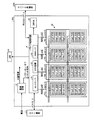
図1は、SSD(Solid State Drive)100の構成例を示すブロック図である。SSD100は、ATAインタフェース(ATA I/F)2などのメモリ接続インタフェースを介してパソコンあるいはCPUコアなどのホスト装置(ホスト)1と接続され、ホスト装置1の外部メモリとして機能する。また、SSD100は、RS232Cインタフェース(RS232C I/F)などの通信インタフェース3を介して、デバッグ用機器200との間でデータを送受信することができる。SSD100は、不揮発性メモリとしてのNANDフラッシュメモリ(以下、NANDメモリと略す)10と、コントローラとしてのドライブ制御回路4と、揮発性メモリとしてのDRAM20と、電源回路5と、状態表示用のLED6などを備えている。
[Configuration of SSD]
FIG. 1 is a block diagram illustrating a configuration example of an SSD (Solid State Drive) 100. The SSD 100 is connected to a host device (host) 1 such as a personal computer or a CPU core via a memory connection interface such as an ATA interface (ATA I / F) 2 and functions as an external memory of the
電源回路5は、ホスト装置1側の電源回路から供給される外部直流電源から複数の異なる内部直流電源電圧を生成し、これら内部直流電源電圧をSSD100内の各回路に供給する。また、電源回路5は、外部電源の立ち上がりまたは立ち下がりを検知し、パワーオンリセット信号またはパワーオフリセット信号を生成して、ドライブ制御回路4に供給する。
The
NANDメモリ10は、この場合、4並列動作を行う4つの並列動作要素10a〜10dを有し、1つの並列動作要素は、2つのNANDメモリパッケージを有する。各NANDメモリパッケージは、積層された複数のNANDメモリチップ(例えば、1チップ=2GB)によって構成されている。図1の場合は、各NANDメモリパッケージは、積層された4枚のNANDメモリチップによって構成されており、NANDメモリ10は64GBの容量を有する。各NANDメモリパッケージが、積層された8枚のNANDメモリチップによって構成されている場合は、NANDメモリ10は128GBの容量を有することになる。
In this case, the
DRAM20は、ホスト装置1とNANDメモリ10間でのデータ転送用キャッシュおよび作業領域用メモリとして機能する。
The
ドライブ制御回路4は、ホスト装置1とNANDメモリ10との間でDRAM20を介してデータ転送制御を行うとともに、SSD100内の各構成要素を制御する。また、ドライブ制御回路4は、状態表示用LED6にステータス表示用信号を供給するとともに、電源回路5からのパワーオン/オフリセット信号を受けて、リセット信号およびクロック信号を自回路内およびSSD100内の各部に供給する機能も有している。
The
各NANDメモリチップは、データ消去の単位であるブロックを複数配列して構成されている。図2は、NANDメモリチップに含まれる1個のブロックの構成例を示す回路図である。各ブロックは、X方向に沿って順に配列された(m+1)個のNANDストリングを備えている(mは、0以上の整数)。(m+1)個のNANDストリングにそれぞれ含まれる選択トランジスタST1は、ドレインがビット線BL0〜BLmに接続され、ゲートが選択ゲート線SGDに共通接続されている。また、選択トランジスタST2は、ソースがソース線SLに共通接続され、ゲートが選択ゲート線SGSに共通接続されている。 Each NAND memory chip is configured by arranging a plurality of blocks which are data erasing units. FIG. 2 is a circuit diagram showing a configuration example of one block included in the NAND memory chip. Each block includes (m + 1) NAND strings arranged in order along the X direction (m is an integer of 0 or more). The select transistors ST1 included in each of (m + 1) NAND strings have drains connected to the bit lines BL0 to BLm and gates commonly connected to the select gate line SGD. In addition, the selection transistor ST2 has a source commonly connected to the source line SL and a gate commonly connected to the selection gate line SGS.
各メモリセルトランジスタMTは、半導体基板上に形成された積層ゲート構造を備えたMOSFET(Metal oxide semiconductor field effect transistor)から構成される。積層ゲート構造は、半導体基板上にゲート絶縁膜を介在して形成された電荷蓄積層(浮遊ゲート電極)、及び電荷蓄積層上にゲート間絶縁膜を介在して形成された制御ゲート電極を含んでいる。メモリセルトランジスタMTは、浮遊ゲート電極に蓄えられる電子の数に応じて閾値電圧が変化し、この閾値電圧の違いに応じてデータを記憶する。メモリセルトランジスタMTは、1ビットを記憶するように構成されていてもよいし、多値(2ビット以上のデータ)を記憶するように構成されていてもよい。 Each memory cell transistor MT is composed of a MOSFET (Metal Oxide Semiconductor Field Effect Transistor) having a stacked gate structure formed on a semiconductor substrate. The stacked gate structure includes a charge storage layer (floating gate electrode) formed on a semiconductor substrate with a gate insulating film interposed therebetween, and a control gate electrode formed on the charge storage layer with an inter-gate insulating film interposed therebetween. It is out. In the memory cell transistor MT, the threshold voltage changes according to the number of electrons stored in the floating gate electrode, and data is stored according to the difference in threshold voltage. The memory cell transistor MT may be configured to store 1 bit, or may be configured to store multiple values (data of 2 bits or more).
各NANDストリングにおいて、(n+1)個のメモリセルトランジスタMTは、選択トランジスタST1のソースと選択トランジスタST2のドレインとの間に、それぞれの電流経路が直列接続されるように配置されている。すなわち、複数のメモリセルトランジスタMTは、隣接するもの同士で拡散領域(ソース領域若しくはドレイン領域)を共有するような形でY方向に直列接続される。 In each NAND string, (n + 1) memory cell transistors MT are arranged such that their current paths are connected in series between the source of the selection transistor ST1 and the drain of the selection transistor ST2. That is, the plurality of memory cell transistors MT are connected in series in the Y direction so that adjacent ones share a diffusion region (source region or drain region).
そして、最もドレイン側に位置するメモリセルトランジスタMTから順に、制御ゲート電極がワード線WL0〜WLnにそれぞれ接続されている。従って、ワード線WL0に接続されたメモリセルトランジスタMTのドレインは選択トランジスタST1のソースに接続され、ワード線WLnに接続されたメモリセルトランジスタMTのソースは選択トランジスタST2のドレインに接続されている。 The control gate electrodes are connected to the word lines WL0 to WLn in order from the memory cell transistor MT located closest to the drain side. Therefore, the drain of the memory cell transistor MT connected to the word line WL0 is connected to the source of the selection transistor ST1, and the source of the memory cell transistor MT connected to the word line WLn is connected to the drain of the selection transistor ST2.
ワード線WL0〜WLnは、ブロック内のNANDストリング間で、メモリセルトランジスタMTの制御ゲート電極を共通に接続している。つまり、ブロック内において同一行にあるメモリセルトランジスタMTの制御ゲート電極は、同一のワード線WLに接続される。この同一のワード線WLに接続される(m+1)個のメモリセルトランジスタMTは1ページとして取り扱われ、このページごとにデータの書き込み及びデータの読み出しが行われる。 The word lines WL0 to WLn connect the control gate electrodes of the memory cell transistors MT in common between the NAND strings in the block. That is, the control gate electrodes of the memory cell transistors MT in the same row in the block are connected to the same word line WL. The (m + 1) memory cell transistors MT connected to the same word line WL are handled as one page, and data writing and data reading are performed for each page.
また、ビット線BL0〜BLmは、ブロック間で、選択トランジスタST1のドレインを共通に接続している。つまり、複数のブロック内において同一列にあるNANDストリングは、同一のビット線BLに接続される。 The bit lines BL0 to BLm connect the drains of the selection transistors ST1 in common between the blocks. That is, NAND strings in the same column in a plurality of blocks are connected to the same bit line BL.
図1に示したように、NANDメモリ10においては、4つの並列動作要素(メモリパッケージ)10a〜10dが各8ビットの4チャネル(4ch)を介してドライブ制御回路4に並列接続されている。4つの並列動作要素10a〜10dを単独動作させるか、並列動作させるか、NANDメモリ10の倍速モードを使用するか否か、という組み合わせにより、下記3種類のアクセスモードが提供される。
(1)8ビットノーマルモード
1chだけ動作させ、8ビット単位で読み書きをするモードである。転送サイズの1単位はページサイズ(4kB)である。
(2)32ビットノーマルモード
4ch並列で動作させ、32ビット単位で読み書きをするモードである。転送サイズの1単位はページサイズ×4(16kB)である。
(3)32ビット倍速モード
4ch並列で動作させ、更に、NANDメモリ10の倍速モードを利用して読み書きをするモードである。転送サイズの1単位はページサイズ×4×2(32kB)である。
As shown in FIG. 1, in the
(1) 8-bit normal mode In this mode, only 1 channel is operated and reading / writing is performed in 8-bit units. One unit of transfer size is a page size (4 kB).
(2) 32-bit normal mode In this mode, 4 channels are operated in parallel, and reading and writing are performed in units of 32 bits. One unit of the transfer size is page size × 4 (16 kB).
(3) 32-bit double speed mode In this mode, 4 channels are operated in parallel, and reading / writing is performed using the double speed mode of the
4ch並列動作する32ビットノーマルモードまたは32ビット倍速モードでは、並列動作する4または8ブロックが、NANDメモリ10としての消去単位となり、並列動作する4または8ページが、NANDメモリ10としての書き込み単位及び読み出し単位となる。
In the 32-bit normal mode or the 32-bit double speed mode that operates in parallel with 4 channels, 4 or 8 blocks that operate in parallel serve as erase units as the
ドライブ制御回路4は、コントローラ41と、ECC(Error correcting code)回路42と、NAND I/F43を備えている。
The
コントローラ41は、ATAインタフェース2を介してホスト装置1との間でデータを送受信すると共に、DRAM20のアクセス制御を行う。
The
NAND I/F43は、NANDメモリ10の各NANDパッケージ10a〜10dとのインタフェース処理を行う。
The NAND I /
ECC回路42は、NANDメモリ10に書き込むデータに対して、誤り検出符号および誤り訂正符号を生成する。また、ECC回路42は、NANDメモリ10から読み出されたデータに対して、誤り検出および誤り訂正を行う。
The
上記構成のSSD100の動作の概略を説明する。ホスト装置1からSSD100に書き込みを要求するデータ(書き込みデータ)が供給されると、コントローラ41は、書き込みデータをDRAM20に一時的に格納する。DRAM20に格納された書き込みデータは、コントローラ41により所定単位毎にECC回路42に供給される。ECC回路42は、書き込みデータに対して、誤り訂正符号及び誤り検出符号を生成する。NAND I/F43は、誤り訂正符号及び誤り検出符号を付加した書き込みデータをNANDメモリ10に書き込む。
An outline of the operation of the
また、SSD100は、ホスト装置1からデータの読み出し要求が入力されると、NAND I/F43は、読み出しを要求されているデータ(読み出しデータ)とこれに付加された誤り訂正符号及び誤り検出符号を読み出して、ECC回路42に供給する。ECC回路42は、読み出しデータの誤りを検出および誤り訂正を行う。誤り訂正後のデータはコントローラ41によりDRAM20に格納された後、ホスト装置1に転送される。
In addition, when a data read request is input from the
[ECC回路]
以下に、ECC回路42の基本的動作手順について説明する。本発明の実施例に係るECC回路42は、NANDメモリ10に書き込むデータに対して、誤り訂正能力の異なる3種類の訂正符号化を行なうことにより、消費電力および回路規模を削減している。第1誤り訂正符号はデータブロックD単位で誤り訂正を行うためのものである。第2誤り訂正符号は、複数のデータブロックDで構成される列単位で誤り訂正を行うためのものである。第3誤り訂正符号は、複数のデータブロックDで構成される行単位で誤り訂正を行うためのものである。誤り訂正能力は、第1誤り訂正符号<第2誤り訂正符号<第3誤り訂正符号の順となっている。
[ECC circuit]
Hereinafter, a basic operation procedure of the
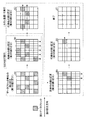
図3は、ECC回路42の誤り訂正原理の概略を説明するための模式図である。同図は、NANDメモリ10から読み出されたデータを示しており、複数データで構成されるデータブロックDが行列(マトリクス)状に配列されている。斜線部分は、誤りデータを含んでいる誤りデータブロックを示している。まず、最初に、データブロックD単位で誤り訂正(第1誤り訂正)を行う(A)。つぎに、誤りが訂正できなかったデータブロックDに対して、列単位での誤り訂正(1回目の第2誤り訂正)を行う(B)。さらに、誤り訂正ができなかったデータブロックDに対して、行単位での誤り訂正(1回目の第3誤り訂正)を行う(C)。再び、誤りが訂正できなかったデータブロックDに対して、列単位での誤り訂正(2回目の第2誤り訂正)を行う(D)。さらに、誤りが訂正できなかったデータブロックDに対して、行単位での誤り訂正(2回目の第3誤り訂正)を行う(E)。これにより、誤りのないデータを復号する(F)。
FIG. 3 is a schematic diagram for explaining the outline of the error correction principle of the
このように、本実施の形態では、まず、データブロック単位での誤り訂正(第1誤り訂正)を行う。ここで、誤り訂正ができなかったデータブロックがある場合には、誤りが無くなるまで、列単位での誤り訂正(第2誤り訂正)と行単位での誤り訂正(第3誤り訂正)を交互に繰り返し実行し、誤りのないデータを復号する。 Thus, in this embodiment, first, error correction (first error correction) is performed in units of data blocks. If there is a data block that could not be corrected, error correction in units of columns (second error correction) and error correction in units of rows (third error correction) are alternately performed until there is no error. Iteratively execute and decode error-free data.
[ECC回路の符号化系の構成]
図4は、ECC回路42の符号化系に関する主要部を示すブロック図である。図5は、ホスト装置10から転送されるデータをDRAM20に格納する場合のフォーマットの一例を示す図である。図6は、NANDメモリ10に転送されるデータのフォーマットの一例を示す図である。
[Configuration of ECC circuit coding system]
FIG. 4 is a block diagram showing a main part related to the encoding system of the
ECC回路42は、図4に示すように、誤り検出符号生成部50−1〜8(誤り検出符号生成手段)と、第1ECC生成部51−1〜8(第1誤り訂正符号生成手段)と、第2ECC生成部52(第2誤り訂正符号生成手段)と、第3ECC生成部53−1〜8(第3誤り訂正符号生成手段)とを備えている。
As shown in FIG. 4, the
誤り検出符号生成部50−1〜8(誤り検出符号生成手段)は、書き込みデータのデータブロックD毎にその誤りを検出するための誤り検出符号を生成する。データブロックDのサイズは、例えば512バイトである。 Error detection code generation units 50-1 to 50-8 (error detection code generation means) generate an error detection code for detecting the error for each data block D of the write data. The size of the data block D is, for example, 512 bytes.
誤り検出符号としては、CRC(Cyclic redundancy checksum)32、CRC16等を用いることができる。本実施の形態では、CRC32を使用し、CRC32(以下、「CRC」と表記する)のサイズを4バイトとしている。誤り検出符号生成部50−1〜8は一般に知られたものを用いることができ、詳細な説明はここでは省略する。 As the error detection code, CRC (Cyclic redundancy checksum) 32, CRC16, or the like can be used. In the present embodiment, CRC 32 is used, and the size of CRC 32 (hereinafter referred to as “CRC”) is 4 bytes. As the error detection code generation units 50-1 to 50-8, generally known ones can be used, and detailed description thereof is omitted here.
第1ECC生成部51−1〜8(第1の誤り訂正符号生成手段)は、データブロックDとその誤り検出符号で構成される第1単位データ毎に、その誤りを訂正するための第1誤り訂正符号を生成する。 The first ECC generation units 51-1 to 5-8 (first error correction code generation means) perform a first error for correcting the error for each first unit data composed of the data block D and its error detection code. A correction code is generated.
第1の誤り訂正符号としては、1ビットあるいは複数ビットの誤りを訂正できる誤り訂正符号を用いることができ、例えば、ハミング符号(Hamming code)やBCH符号(Bose−chaudhuri hocquenghem code)等を用いることができる。本実施の形態では、第1誤り訂正符号としてハミング符号を使用し、ハミング符号のサイズを4バイトとしている。第1ECC生成部51−1〜8は一般に知られたものを用いることができ、詳細な説明はここでは省略する。 As the first error correction code, an error correction code that can correct an error of 1 bit or a plurality of bits can be used. For example, a Hamming code or a BCH code may be used. Can do. In this embodiment, a Hamming code is used as the first error correction code, and the size of the Hamming code is 4 bytes. As the first ECC generation units 51-1 to 51-8, generally known ones can be used, and detailed description thereof is omitted here.
第2ECC生成部52(第2誤り訂正符号生成手段)は、列方向に配列される複数の第1単位データで構成される第2単位データUDa毎に、第2誤り訂正符号を生成する。第2誤り訂正符号を生成する単位となる書き込みデータの数は、達成することが望まれる誤り訂正能力及び採用される誤り訂正符号に応じて決定される。 The second ECC generation unit 52 (second error correction code generation means) generates a second error correction code for each second unit data UDa composed of a plurality of first unit data arranged in the column direction. The number of write data as a unit for generating the second error correction code is determined according to the error correction capability desired to be achieved and the error correction code employed.
第2誤り訂正符号としては、第1誤り訂正符号に比して誤り訂正能力が高いものが用いられ、複数ビットの誤りを訂正できる誤り訂正符号が用いられる。具体的には、BCH符号やLDPC符号(Low density parity check code)等を用いることができる。本実施の形態では、列方向の8個の第1単位データで構成される第2単位データUDa毎にBCH符号を生成し、BCH符号のサイズを24バイトとしている。第2ECC生成部52は一般に知られたものを用いることができ、詳細な説明はここでは省略する。
As the second error correction code, one having higher error correction capability than that of the first error correction code is used, and an error correction code capable of correcting a multi-bit error is used. Specifically, a BCH code, an LDPC code (Low density parity check code), or the like can be used. In the present embodiment, a BCH code is generated for each second unit data UDa composed of eight first unit data in the column direction, and the size of the BCH code is 24 bytes. The second
第3ECC生成部53−1〜8(第3の誤り訂正符号生成手段)は、行方向に配列された複数のデータブロックDで構成される第3単位データUDb毎に、その誤りを訂正するための第3誤訂正符号を生成する。第3誤り訂正符号を生成する単位となるデータブロックDの数は、達成することが望まれる誤り訂正能力及び採用される誤り訂正符号に応じて決定される。 The third ECC generators 53-1 to 5-8 (third error correction code generator) correct the error for each of the third unit data UDb composed of a plurality of data blocks D arranged in the row direction. The third error correction code is generated. The number of data blocks D as a unit for generating the third error correction code is determined according to the error correction capability desired to be achieved and the error correction code employed.
第3誤り訂正符号としては、例えば、複数ビット単位で誤り訂正を行う第2誤り訂正符号を用いた誤り訂正よりも高い能力の誤り訂正を可能とするものが用いられる。具体的には、第3の誤り訂正符号としては、RS符号(Reed−solomon code)等を用いることができる。本実施の形態では、1024個の第1単位データDからなる第3単位データUDbごとに、RS符号を生成し、RS符号のサイズをデータブロックDと同じ512バイトとしている。そして、第3ECC生成部53−1〜53−8は、1個の第3単位データUDbに対して、例えば4個のRS符号を生成する。従って、1個の第3単位データUDbを構成する1024個のデータブロックDのうち4個の書き込みデータの誤りを訂正することができる。第3ECC生成部53は一般に知られたものを用いることができ、詳細な説明はここでは省略する。 As the third error correction code, for example, a code that enables error correction with higher capability than error correction using a second error correction code that performs error correction in units of a plurality of bits is used. Specifically, an RS code (Reed-solomon code) or the like can be used as the third error correction code. In the present embodiment, an RS code is generated for each third unit data UDb including 1024 first unit data D, and the size of the RS code is set to 512 bytes, which is the same as that of the data block D. Then, the third ECC generation units 53-1 to 53-8 generate, for example, four RS codes for one third unit data UDb. Accordingly, it is possible to correct errors in four write data among 1024 data blocks D constituting one third unit data UDb. The third ECC generation unit 53 can use a generally known one, and a detailed description thereof is omitted here.
コントローラ41は、書き込みデータD(1,1)〜D(8,1024)をホスト装置1から受信すると、図5に示すように、DRAM20に、第1ECC生成部51の処理単位である8個のデータブロックD(1,p)〜D(8,p)を列方向に順次格納し、第3ECC生成部53の処理単位である1024個の第1単位データD(q,1)〜D(q,1024)を格納するとともに、列単位で順次、ECC回路42に転送する。pは1〜1024のうちの任意の数、qは1〜8のうちの任意の数である。
When the
誤り検出符号生成部50は、列方向に配列された8個のデータブロックD(1,p)〜D(8,p)に対応して、8個の誤り検出符号生成部50−1〜50−8を備えている。8個の誤り検出符号生成部50−1〜50−8は、8個のデータブロックD(1,p)〜D(8,p)に対して、8個のCRC32を生成する。この8個のCRC32はそれぞれ、これらに対応する8個のデータブロックD(1,p)〜D(8,p)の誤りを検出するために用いられる。この8個のCRC32は、第1ECC生成部51−1〜51−8および第2ECC生成部52に出力される。なお、誤り検出符号生成部50−1〜50−8はそれぞれ、列方向に配列された8個のRS(1,r)〜RS(8,r)に対しても、CRC32を生成する。rは、1〜4のうちの任意の数である。
The error detection code generation unit 50 corresponds to the eight data blocks D (1, p) to D (8, p) arranged in the column direction, and the eight error detection code generation units 50-1 to 50-50. -8. The eight error detection code generation units 50-1 to 50-8 generate eight CRCs 32 for the eight data blocks D (1, p) to D (8, p). Each of the eight CRCs 32 is used to detect errors in the eight data blocks D (1, p) to D (8, p) corresponding thereto. The eight CRCs 32 are output to the first ECC generators 51-1 to 51-8 and the
第1ECC生成部51は、列方向に配列される8個のデータブロックD(1,p)〜D(8,p)に対応して、8個の第1ECC生成部51−1〜51−8を備えている。8個の第1ECC生成部51−1〜51−8は、それぞれ、第1単位データ毎、すなわち、8個のデータブロックD(1,p)〜D(8,p)および8個のCRC(1,p)〜CRC(8,p)から、それぞれハミング符号を生成する。この8個のハミング符号はそれぞれ、これらに対応する8個の単位データD(1,p)〜D(8,p)第1誤り訂正に用いられる。この8個のハミング符号は、第2ECC生成部52に出力される。なお、第1ECC生成部51−1〜51−8はそれぞれ、列方向に配列された8個のRS(1,r)〜RS(8,r)および対応するCRC32に対してもそれぞれハミング符号を生成する。rは、1〜4のうちの任意の数である。
The first
第2ECC生成部52は、列方向に配置された8個の第1単位データ、すなわち、データブロックD(1,p)〜D(8,p)と、これらに対応する8個のCRC(1,p)〜CRC(8,p)とで構成される第2単位データUDa毎に、1個のBCH符号を生成する。このBCH符号は第2単位データUDa内(ECC1(1,p)〜ECC1(8,p)を除く)の誤りを訂正するために用いられる。本実施形態では、第2単位データUDaとBCH符号とからなるデータのサイズ、1ページ(NANDメモリ10の最小アクセス単位)分のサイズに対応する。
The second
第3ECC生成部53は、行方向に配列された1024個のデータブロックD(q,1)〜D(q,1024)からなる第3単位データUDb毎に、1個のRS符号を生成する。第3のECC生成部53は、DRAM20に格納される書き込みデータの行に対応する8個の第3ECC生成部53−1〜53−8を備えている。第3ECC生成部53−1は、第3単位データUDbを格納するバッファを備えている。データD(1,1)〜D(1,1024)からなる第3単位データUDb1に対して、4個のRS(1,1)〜RS(1,4)を生成する。2〜8行にそれぞれ対応する第3ECC生成部53−2〜53−8についても同様である。
The third ECC generation unit 53 generates one RS code for each third unit data UDb including 1024 data blocks D (q, 1) to D (q, 1024) arranged in the row direction. The third ECC generation unit 53 includes eight third ECC generation units 53-1 to 53-8 corresponding to the write data rows stored in the
データブロックD、CRC、ハミング符号、BCH符号、及びRS符号は、図6に示したページ毎に、NAND IF43からNANDメモリ12に転送される。NANDメモリ10は、これらのデータを、ページ順に格納する。例えば、1つのメモリブロックBLKが1028ページで構成されている場合、図6に示したデータは、NANDメモリ10内の1つのメモリブロックBLKに格納される(8ビットノーマルモードの場合)。なお、32ビットモード(32ビットノーマルモード、32ビット倍速モード)の場合には、各Chのメモリチップに並列に書き込まれる。
The data block D, CRC, Hamming code, BCH code, and RS code are transferred from the NAND IF 43 to the NAND memory 12 for each page shown in FIG. The
[ECC回路の符号化系のデータ書き込み動作]
次に、データ書き込み動作におけるECC回路42の誤り検出符号生成動作及び誤り
訂正符号生成動作について、図4〜図9を参照して説明する。
[Data writing operation of encoding system of ECC circuit]
Next, the error detection code generation operation and the error correction code generation operation of the
まず、図5において、コントローラ41は、DRAM20に、NANDメモリ10への書き込み対象となるデータを、8個のデータブロックD(1,q)〜D(8,1)毎に、順次、列方向に書き込んで、データブロックD(1,1)〜D(8,1024)を格納すると共に、DRAM20に格納したデータを列単位で順次、データブロックD(1,q)〜D(8,1)を、誤り検出符号生成部50−1〜8、第1ECC生成部51−1〜8、第2ECC生成部52、第3ECC生成部53−1〜8に出力する。
First, in FIG. 5, the
続いて、図7に示すように、誤り検出符号生成部50−1〜50−8は、転送されてくる8個のデータブロックD(1,1)〜D(8,1)に対して、8個の誤り検出符号CRC(1,1)〜CRC(8,1)を生成する。そして、第1ECC生成部51−1〜51−8は、それぞれ、8個の書き込みデータD(1,1)〜D(8,1)および8個のCRC(1,1)〜CRC(8,1)から、それぞれハミング符号ECC1(1,1)〜ECC1(8,1)を生成する。 Subsequently, as illustrated in FIG. 7, the error detection code generation units 50-1 to 50-8 perform the eight data blocks D (1, 1) to D (8, 1) transferred. Eight error detection codes CRC (1, 1) to CRC (8, 1) are generated. The first ECC generators 51-1 to 51-8 respectively include eight write data D (1,1) to D (8,1) and eight CRC (1,1) to CRC (8, From 1), Hamming codes ECC1 (1, 1) to ECC1 (8, 1) are generated.
続いて、図8に示すように、8個のデータブロックD(1,1)〜D(8,1)および対応する8個の誤り検出符号CRC(1,1)〜CRC(8,1)で構成される第2単位データUDa1は、第2ECC生成部52に出力される。第2のECC生成部52は、第2単位データUDa1を用いて、この第2単位データUDa1の誤りを訂正するためのBCH符号ECC2を生成する。このBCH符号ECC2が、第2単位データUDa1の後ろに繋げられて、ページ1(Page1)が構成される。このページ1は、NANDメモリ10に格納される。
Subsequently, as shown in FIG. 8, eight data blocks D (1,1) to D (8,1) and corresponding eight error detection codes CRC (1,1) to CRC (8,1). The second unit data UDa1 configured by is output to the second
ページ2〜ページ1024についても、上記同様の生成動作により、図6に示すデータ
が生成される。そして、ページ2〜ページ1024は、NANDメモリ10に格納される。
For
さらに、図9に示すように、第3ECC生成部53−1〜53−8は、列単位で順次、転送される第1単位データD(1,q)〜D(8,q)をそれぞれバッファに格納し、第3単位データUDb1、UDb2、・・・UDb8を用いて、4個のRS(p,1)〜R
S(p,4)をそれぞれ生成する。具体的には、第3ECC生成部53−1は、第3単位データUDb1を用いて、4個のRS(1,1)〜RS(1,4)を生成する。第3ECC生成部53−2〜53−8によるRS生成動作についても、RS生成部53−1と同様である。本実施形態では、第3ECC生成部53−1〜53−8は、訂正符号生成動作を並行して行っている。このように、第3ECC生成部53−1〜53−8を並行して動作させることによって、処理時間を短縮させることができる。
Further, as shown in FIG. 9, the third ECC generators 53-1 to 53-8 buffer the first unit data D (1, q) to D (8, q), which are sequentially transferred in units of columns, respectively. And using the third unit data UDb1, UDb2,... UDb8, four RS (p, 1) to R
S (p, 4) is generated respectively. Specifically, the third ECC generation unit 53-1 generates four RS (1, 1) to RS (1, 4) using the third unit data UDb1. The RS generation operation by the third ECC generation units 53-2 to 53-8 is the same as that of the RS generation unit 53-1. In the present embodiment, the third ECC generators 53-1 to 53-8 perform correction code generation operations in parallel. In this way, the processing time can be shortened by operating the third ECC generation units 53-1 to 53-8 in parallel.
RS符号を用いた場合、通常は、4個の冗長符号を用いて2個の誤り位置情報と2個の誤り訂正情報を得るため、2個の誤りの訂正が可能である。しかし、本実施形態では、データブロックDの誤り位置を特性するために、別途CRCを用いている。従って、本実施形態では、4個の冗長符号を用いて4個の誤りを訂正することが可能となる。すなわち、1024個のデータブロックD(1,1)〜D(1,1024)のうち4個の誤りを訂正することが可能となる。 When an RS code is used, normally, two error position information and two error correction information are obtained using four redundant codes, so that two errors can be corrected. However, in this embodiment, in order to characterize the error position of the data block D, a separate CRC is used. Therefore, in this embodiment, it is possible to correct four errors using four redundant codes. That is, it is possible to correct four errors out of 1024 data blocks D (1,1) to D (1,1024).
続いて、誤り符号生成部50−1〜50−8はデータブロックDの場合と同様に、RS(1,1)〜RS(8,4)毎に、CRC(1,1025)〜(8,1028)をそれぞれ生成する。また、第1ECC符号生成部51−1〜51−8は、RS(1,1)〜RS(8,4)および対応するCRC(1,1025)〜(8,1028)毎に、ハミング符号(1,1025)〜(8,1028)を生成する。さらに、第2ECC訂正部52は、
RS(1,1)〜RS(8,4)および対応するCRC(1,1025)〜(8,1028)に対して、BCH符号ECC2を生成し、このBCH符号ECC2が、これらの後ろに繋げられて、ページ1025が構成される。このページ1025は、NANDメモリ10に転送されて格納される。ページ1026〜ページ1028についても、上記同様の生成動作により、図6に示すデータが生成される。そして、ページ1026〜ページ1028は、NANDメモリ10に転送されて格納される。
[ECC回路の復号系回路の構成]
Subsequently, similarly to the case of the data block D, the error code generation units 50-1 to 50-8 perform CRC (1, 1025) to (8, 8) for each RS (1, 1) to RS (8, 4). 1028) respectively. Further, the first ECC code generation units 51-1 to 51-8 perform a Hamming code (RS) for each of RS (1,1) to RS (8,4) and corresponding CRC (1,1025) to (8,1028). 1,1025) to (8,1028) are generated. Further, the second
For RS (1, 1) to RS (8, 4) and corresponding CRC (1, 1025) to (8, 1028), a BCH code ECC2 is generated, and this BCH code ECC2 is connected to the back of these. Thus, the
[Configuration of ECC Circuit Decoding System]
図10は、ECC回路42の復号系に関する主要部を示すブロック図である。図11〜図19は、ECC回路42のデータ読み出しを説明するための図である。ECC回路42は、図10に示すように、誤り検出部60と、第1ECC訂正部61−1〜61−8と、第2ECC訂正部62と、第3ECC訂正部63−1〜61−8とを備えている。同図において、説明の簡単のため、コントローラ41およびNAND I/F43の図示を省略している。
FIG. 10 is a block diagram showing a main part related to the decoding system of the
SSD100は、ホスト装置1からデータの読み出し要求が入力されると、NAND I/F43により、NANDメモリ10内の1つのメモリブロックBLKに格納されたブロックデータ(図6に示すデータ)が読み出され(8ビットノーマルモードの場合)、コントローラ41によりDRAM20に格納される。DRAM20は、図6に示すブロックデータを格納する。なお、32ビットモード(32ビットノーマルモード、32ビット倍速モード)の場合には、各Chのメモリチップから並列に読み出される。
When a data read request is input from the
第1ECC訂正部61は、列方向に配列された8個のデータブロックD(1,p)〜D(8,p)および対応するCRC(1,p)〜CRC(8,p)に対して、すなわち、行数に対応して、8個の第1ECC訂正部61−1〜61−8を備えている。 The first ECC correction unit 61 applies the eight data blocks D (1, p) to D (8, p) and the corresponding CRC (1, p) to CRC (8, p) arranged in the column direction. In other words, eight first ECC correction units 61-1 to 61-8 are provided corresponding to the number of rows.
第1ECC訂正部61−1〜61−8は、列方向に配列された8個のデータブロックD(1,p)〜D(8,p)およびCRC(1,p)〜CRC(8,p)に対して、ハミング符号ECC1(1,p)〜ECC1(8,p)を用いてそれぞれ第1誤り訂正を行い、DRAM20の格納されたデータのうち、第1の誤り訂正済データDC1−1〜DC1−8に対応するデータを更新する。同様に、RS(1,1)〜RS(8,4)および対応するCRC(1,1025)〜(8,1028)に対しても第1誤り訂正を行う。第1ECC訂正部61−1〜61−8は一般に知られたものを用いることができ、詳細な説明はここでは省略する。
The first ECC correction units 61-1 to 61-8 include eight data blocks D (1, p) to D (8, p) and CRC (1, p) to CRC (8, p) arranged in the column direction. ), The first error correction is performed using the Hamming codes ECC1 (1, p) to ECC1 (8, p), respectively, and the first error corrected data DC1-1 among the data stored in the
誤り検出部60は、列方向に配列された8個のデータブロックD(1,p)〜D(8,p)およびそのCRC(1,p)〜CRC(8,p)に対応して、すなわち、行数に対応して、8個の誤り検出部60−1〜60−8を備えている。 The error detection unit 60 corresponds to the eight data blocks D (1, p) to D (8, p) and the CRC (1, p) to CRC (8, p) arranged in the column direction, That is, eight error detection units 60-1 to 60-8 are provided corresponding to the number of rows.
誤り検出部60−1〜60−8は、それぞれ、8個のデータブロックD(1,p)〜D(8,p)に対して生成された8個のCRC(1,p)〜CRC(8,p)を用いて、第1単位データD(1,p)〜D(8,p)内の誤りを検出する。誤り検出部60−1〜60−8は一般に知られたものを用いることができ、詳細な説明はここでは省略する。 The error detection units 60-1 to 60-8 respectively generate eight CRC (1, p) to CRC (CRC) generated for the eight data blocks D (1, p) to D (8, p). 8, p) is used to detect errors in the first unit data D (1, p) to D (8, p). As the error detection units 60-1 to 60-8, generally known ones can be used, and detailed description thereof is omitted here.
第2ECC訂正部62は、ページごとに生成されたBCH符号ECC2を用いて、8個の第1単位データD(1,p)〜D(8,p)と対応する8個のCRC(1,p)〜CRC(8,p)とで構成される第2単位データ内の第2誤り訂正を行い、DRAM20の格納されたデータのうち、第2の誤り訂正済データDC2に対応するデータを更新する。ページ1025〜1024についても同様に第2誤り訂正が行われる。
The second
第3ECC訂正部63は、列方向に配列された8個の第1単位データD(1,p)〜D(8,p)に対応して、8個の第3ECC訂正部63−1〜63−8を備えている。第3ECC訂正部63−1は、4個のRS(1,1)〜RS(1,4)を用いて、行方向に配列された1024個の読み出しデータD(1,1)〜D(1,1024)からなる第3単位データUDb1内の第3誤り訂正を行う。同様に、第3ECC訂正部63−2〜63−8は、第3単位データUDb1〜UDb8内の第3誤り訂正を行う。第3ECC訂正部63−1〜63−8は一般に知られたものを用いることができ、詳細な説明はここでは省略する。
The third ECC correction unit 63 corresponds to the eight first ECC correction units 63-1 to 63-63 corresponding to the eight first unit data D (1, p) to D (8, p) arranged in the column direction. -8. The third ECC correction unit 63-1
本実施形態では、4個のリードソロモン符号RS(1,1)〜RS(1,4)が全て誤り訂正に用いられる。従って、第3ECC訂正部63−1は、1024個の読み出しデータD(1,1)〜D(1,1024)のうち4個の読み出しデータを復元することができる。2〜8行にそれぞれ対応する第3ECC訂正部63−2〜63−8についても同様である。第3ECC訂正部63−1〜63−8により訂正された第3誤り訂正済データDC3は、DRAM20に転送され、DRAM20に格納されたデータのうち、第3誤り訂正済データDC3に対応するデータが更新される。
In this embodiment, all four Reed-Solomon codes RS (1, 1) to RS (1, 4) are used for error correction. Therefore, the third ECC correction unit 63-1 can restore four read data out of the 1024 read data D (1,1) to D (1,1024). The same applies to the third ECC correction units 63-2 to 63-8 corresponding to 2 to 8 rows, respectively. The third error corrected data DC3 corrected by the third ECC correction units 63-1 to 63-8 is transferred to the
第1ECC訂正部61−1〜61−8、第2ECC訂正部62、および第3ECC訂正部63−1〜61−8により訂正されたデータブロックD(1,1)〜D(8,1024)のデータは、コントローラ41によりホスト装置に転送される。
Of the data blocks D (1,1) to D (8,1024) corrected by the first ECC correction units 61-1 to 61-8, the second
[ECC回路の復号系のデータ読み出し動作]
次に、データ読み出し動作におけるECC回路42の誤り検出動作及び誤り訂正動作
について、図11〜図19を参照して説明する。
[Data read operation of decoding system of ECC circuit]
Next, the error detection operation and error correction operation of the
誤り訂正動作に先立って、NANDメモリ10内の1個のメモリブロックBLKに格納されたブロックデータ(図6に示すデータ)が、DRAM20に転送される(8ビットノーマルモードの場合)。DRAM20は、図6に示すブロックデータを格納する。
Prior to the error correction operation, block data (data shown in FIG. 6) stored in one memory block BLK in the
第1ECC訂正部61−1〜61−8には、ページ1〜ページ1028のデータがページ単位(BCH符号ECC2を除く)で、順次転送され、各ページのそれぞれのデータブロックD(1,1)〜D(8,1024)およびそのCRC(1,1)〜CRC(8,1024、RS(1,1)〜RS(8,4)およびそのCRC(1,1025)〜CRC(8,1028)に対して、ハミング符号ECC1(1,1)〜ECC1(8,1028)を用いてそれぞれ第1誤り訂正を行い、第1誤り訂正済みデータDC1−1〜8をDRAM20に格納する。
Data of
続いて、誤り検出部60−1〜60−8による誤り検出動作が行われる。すなわち、誤り検出部60−1〜60−8にはそれぞれ、各ページのそれぞれの第1誤り訂正済みの第1単位データD(1,1)〜D(8,1024)とそのCRC(1,1)〜CRC(8,1024)、および第1の誤り訂正済みのRS(1,1)〜RS(8,4)とそのCRC(1,1025)〜CRC(8,1028)がDRAM20から転送される。
Subsequently, an error detection operation is performed by the error detection units 60-1 to 60-8. That is, each of the error detection units 60-1 to 60-8 includes the first error corrected first unit data D (1,1) to D (8,1024) and its CRC (1, 1) to CRC (8,1024), and the first error corrected RS (1,1) to RS (8,4) and its CRC (1,1025) to CRC (8,1028) are transferred from the
誤り検出部60−1〜60−8は、それぞれ、ページ単位で、第1誤り訂正後のデータブロックD(1,1)〜D(8,1024)および第1誤り訂正後のRS(1,1)〜RS(8,4)内の誤りを、それぞれCRC(1,1)〜CRC(8,1028)を用いて検出する。そして、誤り検出部60−1〜60−8はそれぞれ、誤り検出の結果、どの読み出しデータブロックDおよびRS符号RSに誤りが存在するかを示す第1誤り情報S1〜S8をページ単位で生成する。この第1誤り情報S1〜S8はそれぞれ、第2ECC訂正部62に転送される。なお、誤り検出部60−1〜60−8で誤りが存在すると分かったデータブロックDは、第1誤り訂正済みデータDC1-1〜8ではなく、訂正前のデータブロックDを第2ECC訂正部62に転送する。これは、誤り検出部60−1〜60−8で誤りが見つかったデータブロックDは,訂正不可能であった、つまり第1ECC訂正部61−1〜61−8での訂正能力を超えた誤りが含まれていることを意味し、第1ECC訂正部61−1〜61−8での誤り訂正は、結果としてさらなる誤りを付加することになるからである。従って、さらに誤りを付加したデータよりも、訂正前のデータのほうが誤りが少ないので、訂正前のデータを第2ECC訂正部62に送る。RS(1,1)〜RS(8,4)に関しても同様である。
The error detection units 60-1 to 60-8 are, in page units, data blocks D (1, 1) to D (8, 1024) after the first error correction and RS (1, 1, after the first error correction, respectively. Errors in 1) to RS (8, 4) are detected using CRC (1, 1) to CRC (8, 1028), respectively. Then, each of the error detection units 60-1 to 60-8 generates, in page units, first error information S1 to S8 indicating which read data block D and RS code RS have an error as a result of error detection. . Each of the first error information S1 to S8 is transferred to the second
図11は、第1誤り訂正後の誤り検出を説明するための図であり、図12は、第1誤り情報S1〜S8の一例を示す図である。図11および図12において、第1誤り訂正後の誤り検出で誤りがない第1単位データについては、第1誤り情報S=0、第1誤り訂正後の誤り検出で誤りを検出した第1単位データについては、第1誤り情報S=1とする。図11および図12に示す例では、第1単位データ1,4,5に誤りがあることを示している。この誤りがある第1単位データが第2誤り訂正の対象となる。
FIG. 11 is a diagram for explaining error detection after the first error correction, and FIG. 12 is a diagram illustrating an example of the first error information S1 to S8. In FIG. 11 and FIG. 12, for the first unit data having no error in the error detection after the first error correction, the first error information S = 0, the first unit in which the error is detected by the error detection after the first error correction For data, the first error information S = 1. In the examples shown in FIGS. 11 and 12, it is indicated that the
第2ECC訂正部62には、ページ単位で、第1誤り訂正後の第2単位データUDa1〜UDa1028および第1誤り情報S1〜S8が転送される。第2ECC訂正部62は、第2単位データUDaに含まれるBHC符号ECC2を使用し、第1誤り情報S1〜S8を参照して、第2誤り訂正の対象となる第1単位データに対して第2誤り訂正を行う。第2ECC訂正部62により訂正された第2誤り訂正済データDC2は、DRAM20に転送され、DRAM20に格納されたデータのうち、第2誤り訂正済データDC2に対応するデータを更新する。
Second unit data UDa1 to UDa1028 and first error information S1 to S8 after the first error correction are transferred to the second
続いて、誤り検出部60−1〜60−8による誤り検出動作が行われる。すなわち、誤り検出部60−1〜60−8には、ページ単位で、それぞれ、各ページのそれぞれの第2誤り訂正済みのデータブロックD(1,1)〜D(8,1024)とそのCRC(1,1)〜CRC(8,1024)、および第2誤り訂正済みのRS(1,1)〜RS(8,4)とそのCRC(1,1025)〜CRC(8,1028)がDRAM20から転送される。
Subsequently, an error detection operation is performed by the error detection units 60-1 to 60-8. That is, each of the error detection units 60-1 to 60-8 includes, in page units, the second error-corrected data blocks D (1,1) to D (8,1024) of each page and their CRCs. (1,1) to CRC (8,1024), the second error corrected RS (1,1) to RS (8,4) and its CRC (1,1025) to CRC (8,1028) are
誤り検出部60−1〜60−8は、それぞれ、第2誤り訂正後のデータブロックD(1,1)〜D(8,1024)および第2誤り訂正後のRS(1,1)〜RS(8,4)内の誤りを、それぞれCRC(1,1)〜CRC(8,1028)を用いて検出する。そして、誤り検出部60−1〜60−8はそれぞれ、誤り検出の結果、どの第1単位データおよびRS符号RSに誤りが存在するかを示す第2誤り情報S1〜S8をページ単位で生成する。この第2誤り情報S1〜S8はそれぞれ、第3ECC訂正部63−1〜63−8に送られる。なお、第1誤り訂正の場合と同様に、誤り検出部60−1〜60−8で誤りが存在すると分かったデータブロックDは、第2誤り訂正済みデータDC2ではなく、訂正前のデータブロックDを第3ECC訂正部63−1〜63−8に転送する。これは、誤り検出部60−1〜60−8で誤りが見つかったデータブロックDは、訂正不可能であった、すなわち第2ECC訂正部62−1〜62−8での訂正能力を超えた誤りが含まれていることを意味し、第2ECC訂正部62−1〜62−8での誤り訂正は、結果としてさらなる誤りを付加していることになるからである。したがって、さらに誤りを付加したデータよりも、訂正前のデータのほうが誤りが少ないので、訂正前のデータを第3ECC訂正部63−1〜63−8に送る。RS(1,1)〜RS(8,4)についても同様である。本実施形態では、誤り検出部60−1〜60−8は、誤り検出動作を並行して行っている。このように、誤り検出部60−1〜60−8を並行して動作させることによって、処理時間を短縮させることができる。 The error detection units 60-1 to 60-8 respectively receive the second error-corrected data blocks D (1,1) to D (8,1024) and the second error-corrected RS (1,1) to RS. Errors in (8, 4) are detected using CRC (1, 1) to CRC (8, 1028), respectively. Then, each of the error detection units 60-1 to 60-8 generates, as a result of error detection, second error information S1 to S8 indicating which first unit data and the RS code RS have an error in units of pages. . The second error information S1 to S8 are sent to the third ECC correction units 63-1 to 63-8, respectively. As in the case of the first error correction, the data block D that the error detection units 60-1 to 60-8 have found to have an error is not the second error-corrected data DC2 but the data block D before correction. Are transferred to the third ECC correction units 63-1 to 63-8. This is because the data block D in which an error was found in the error detection units 60-1 to 60-8 could not be corrected, that is, the error exceeded the correction capability of the second ECC correction units 62-1 to 62-8. This is because the error correction in the second ECC correction units 62-1 to 62-8 adds a further error as a result. Accordingly, since the data before the correction has fewer errors than the data to which the error is added, the data before the correction is sent to the third ECC correction units 63-1 to 63-8. The same applies to RS (1, 1) to RS (8, 4). In the present embodiment, the error detection units 60-1 to 60-8 perform error detection operations in parallel. Thus, the processing time can be shortened by operating the error detection units 60-1 to 60-8 in parallel.
図13は、第2誤り訂正後の誤り検出を説明するための図であり、図14は、第2誤り訂正後の第2誤り情報S1〜S8の一例を示す図である。図13および図14において、第2誤り訂正後の誤り検出で誤りがない第1単位データについては、第2誤り情報S=0、第2の誤り訂正後の誤り検出で誤りを検出したブロックについては、第2誤り情報S=1とする。図13および図14に示す例では、第1単位データ5に誤りがあることを示している。この誤りがある第1単位データが第3誤り訂正の対象となる。
FIG. 13 is a diagram for explaining error detection after the second error correction, and FIG. 14 is a diagram illustrating an example of the second error information S1 to S8 after the second error correction. In FIG. 13 and FIG. 14, for the first unit data having no error in error detection after the second error correction, the second error information S = 0, and the block in which an error is detected in the error detection after the second error correction Is second error information S = 1. In the examples shown in FIGS. 13 and 14, it is indicated that there is an error in the
図15は、第2ECC訂正部62による1回目の誤り訂正後のブロックデータの一例を示す図である。斜線は、第2ECC訂正部62による1回目の誤り訂正によっても訂正不能であるため、誤り検出部60−1〜60−8により誤りが検出されたデータを示している。
FIG. 15 is a diagram illustrating an example of block data after the first error correction by the second
なお、第2ECC訂正部62による1回目の誤り訂正の結果、全ての読み出しデータに誤りが存在しない場合は、誤り訂正動作はここで終了する。すなわち、後述する第3ECC訂正部63による誤り訂正は行われない。例えば、第3ECC訂正部63は電源回路5からの電源供給の停止、或いはクロック回路(図示せず)からのクロック信号の供給の停止等によって、誤り訂正動作を停止する。これにより、誤りが少ない場合のデータ読み出し時間を短縮することができる。また、第3ECC訂正部63による誤り訂正動作が行われないため、消費電力を低減することができる。
If there is no error in all the read data as a result of the first error correction by the second
続いて、第3ECC訂正部63による1回目の誤り訂正動作が行われる。すなわち、行方向に配列された1024個のデータブロックD(1,1)〜D(1,1024)からなる第3単位データUDb1と、これらに対応して生成された4個のRS(1,1)〜RS(1,4)とが、DRAM20から第3ECC訂正部63−1に送られる。第3ECC訂正部63−1は、RS(1,1)〜RS(1,4)を用いて、データブロックD(1,1)〜D(1,1024)内の誤りを訂正する。2〜8行にそれぞれ対応する第3ECC訂正部63−2〜63−8についても同様である。
Subsequently, the first error correction operation by the third ECC correction unit 63 is performed. That is, the third unit data UDb1 composed of 1024 data blocks D (1,1) to D (1,1024) arranged in the row direction, and four RSs (1,1, 1) to RS (1, 4) are sent from the
本実施形態では、第3ECC訂正部63−1〜63−8は、訂正動作を並行して行っている。このように、第3ECC訂正部63−1〜63−8を並行して動作させることによって、処理時間を短縮させることができる。第3ECC訂正部63−1〜63−8により訂正された第3誤り訂正済データDC3は、DRAM20に送られる。DRAM20は、格納されたデータのうち、第3の誤り訂正済データDC3に対応するデータを更新する。
In the present embodiment, the third ECC correction units 63-1 to 63-8 perform correction operations in parallel. Thus, the processing time can be shortened by operating the third ECC correction units 63-1 to 63-8 in parallel. The third error corrected data DC3 corrected by the third ECC correction units 63-1 to 63-8 is sent to the
図16は、第3ECC訂正部63による1回目の第3の誤り訂正後のブロックデータの一例を示す図である。図16に示すように、読み出しデータD(1,2)及び(1,6)内の誤りが、第3ECC訂正部63−1により訂正されている。また、読み出しデータD(8,1)及び(8,1022)内の誤りが、第3ECC訂正部63−8により訂正されている。 FIG. 16 is a diagram illustrating an example of block data after the first third error correction by the third ECC correction unit 63. As shown in FIG. 16, the errors in the read data D (1, 2) and (1, 6) are corrected by the third ECC correction unit 63-1. In addition, errors in the read data D (8, 1) and (8, 1022) are corrected by the third ECC correction unit 63-8.
なお、前述したように、第3ECC訂正部63による誤り訂正に先立って、誤り検出部60を用いて誤りが存在する読み出しデータの位置を特定している。よって、第3ECC訂正部63は、誤りが検出された読み出しデータのみに対して誤り訂正を行えばよい。これにより、第3ECC訂正部63による訂正時間を短縮することができ、また消費電力を低減することができる。 As described above, prior to error correction by the third ECC correction unit 63, the error detection unit 60 is used to specify the position of read data in which an error exists. Therefore, the third ECC correction unit 63 may perform error correction only on read data in which an error is detected. Thereby, the correction time by the 3rd ECC correction | amendment part 63 can be shortened, and power consumption can be reduced.
続いて、ページ1〜ページ1028に対して、第2ECC訂正部62による2回目の第2の誤り訂正が行われる。この第2の誤り訂正動作は、前述した第2ECC訂正部62による1回目の誤り訂正と同じである。図17は、第2ECC訂正部62による2回目の第2の誤り訂正後のブロックデータの一例を示す図である。図17に示すように、読み出しデータD(2,1)、(3,2)、及び(2,1022)内の誤りが、第2ECC訂正部62により訂正されている。
Subsequently, a second second error correction by the second
続いて、誤り検出部60−1〜60−8は、全てのデータブロックD及びRS符号の誤りを検出する。この検出動作は、前述した誤り検出部60−1〜60−8による1回目の誤り検出動作と同じである。続いて、第3単位データUDb1〜UDb8に対してそれぞれ、第3ECC訂正部63−1〜63−8による2回目の第3誤り訂正が行われる。この第3誤り訂正動作は、前述した第3ECC訂正部63−1〜63−8による1回目の誤り訂正と同じである。 Subsequently, the error detection units 60-1 to 60-8 detect errors in all the data blocks D and RS codes. This detection operation is the same as the first error detection operation by the error detection units 60-1 to 60-8 described above. Subsequently, second third error correction is performed on the third unit data UDb1 to UDb8 by the third ECC correction units 63-1 to 63-8, respectively. This third error correction operation is the same as the first error correction by the third ECC correction units 63-1 to 63-8.
図18は、第3ECC訂正部63による2回目の第3誤り訂正後のブロックデータの一例を示す図である。図18に示すように、データブロックD(2,5)内の誤りが、第3ECC訂正部63−2により訂正されている。また、データブロックD(3,4)、(3,7)、及び(3,1023)内の誤りが、第3ECC訂正部63−3により訂正されている。これにより、データブロックD(1,1)〜D(8,1024)の誤りが全て訂正されたことになる。 FIG. 18 is a diagram illustrating an example of block data after the second third error correction by the third ECC correction unit 63. As shown in FIG. 18, the error in the data block D (2, 5) is corrected by the third ECC correction unit 63-2. Further, errors in the data blocks D (3, 4), (3, 7), and (3, 1023) are corrected by the third ECC correction unit 63-3. As a result, all the errors in the data blocks D (1, 1) to D (8, 1024) are corrected.
その後、誤りが全て訂正されたデータブロックD(1,1)〜D(8,1024)がDRAM20からホスト装置1に出力される。
Thereafter, the data blocks D (1, 1) to D (8, 1024) in which all errors are corrected are output from the
図19は、NANDメモリ10にデータを書き込んでからの経過時間と、必要訂正能力との関係を示す図である。図19に示すように、経過時間が長くなると、NANDメモリ10に書き込まれたデータのうち誤りの数が増加する。そこで、誤りの数の増加に合わせて誤り訂正能力を変化させる。そして、過剰または不十分な誤り訂正能力が使用されないように、第1誤り訂正部61〜第3誤り訂正部63の誤り訂正能力が決定される。具体的には、経過時間が短い間は、第1誤り訂正部61のみによって誤り訂正ができるとともに、経過時間が所定時間(誤り数が急激に増加する時間)を過ぎた後は第1の誤り訂正部61、第2誤り訂正部62、及び第3誤り訂正部63によって誤りが訂正できるように、第1誤り訂正部61〜第3誤り訂正部63の誤り訂正能力が決定される。
FIG. 19 is a diagram showing the relationship between the elapsed time since data was written to the
以上説明したように、本実施形態によれば、まず、読み出しデータに対して、第1誤り訂正符号(ハミング符号)を用いて第1誤り訂正し、この第1誤り訂正結果を、第2誤り訂正符号(BHC符号)を用いてさらに第2誤り訂正し、さらに、第2誤り訂正結果を、第3誤り訂正符号(RS符号)を用いて第3誤り訂正することができる。従って、第1誤り訂正符号〜第3誤り訂正符号の訂正能力を低くした場合でも、所望の訂正能力を確保することができ、また、回路規模を低減することができる。 As described above, according to the present embodiment, first, the first error correction is performed on the read data using the first error correction code (hamming code), and the first error correction result is converted to the second error correction result. The second error correction can be further performed using the correction code (BHC code), and the second error correction result can be further corrected using the third error correction code (RS code). Therefore, even when the correction capabilities of the first error correction code to the third error correction code are lowered, the desired correction capability can be ensured and the circuit scale can be reduced.
また、小程度の誤り訂正能力を持つ第1誤り訂正符号(ハミング符号)と、中程度の誤り訂正能力を持つ第2誤り訂正符号(BCH符号)と、高程度の誤り訂正能力を持つ第3誤り訂正符号(RS符号)を3重にかけることにより、高程度の誤り訂正の復号化の頻度をきわめて減らすことができ、この結果、ハードウェアを持たなくても、ソフトウェアで十分処理できるようになり、回路規模が削減できる。 In addition, a first error correction code (Hamming code) having a small error correction capability, a second error correction code (BCH code) having a medium error correction capability, and a third error correction capability having a high error correction capability. By multiplying the error correction code (RS code) in triple, the frequency of decoding of a high degree of error correction can be greatly reduced, and as a result, sufficient processing can be performed by software without having hardware. Thus, the circuit scale can be reduced.
また、第1ECC訂正部61による第1誤り訂正の結果、全ての読み出しデータに誤り
が存在しない場合は、第2ECC訂正部62および第3ECC訂正部63による誤り訂正は行われない。これにより、誤りが少ない場合のデータ読み出し時間を短縮することができる。すなわち、誤りが少ない場合のデータ読み出し時間を短縮と、誤りが多い場合の高い訂正能力との両立が可能となる。さらに、第2ECC訂正部62および第3ECC訂正部63の動作を停止することにより、消費電力を低減することができる。
If there is no error in all read data as a result of the first error correction by the first ECC correction unit 61, the error correction by the second
また、第2誤り訂正符号(BCH符号)を用いて列方向のデータの誤りを訂正し、一方、
第3誤り訂正符号(RS符号)を用いて行方向のデータの誤りを訂正している。よって、NAND型フラッシュメモリ1のメモリブロック内の全ページに跨る誤り訂正が可能となる。さらに、記憶されるデータの位置に起因して誤り発生確率が大きく異なるような半導体メモリに対しては、誤り発生確率が大きい領域を何度も誤り訂正することができるため、本実施形態は特に有効である。
In addition, an error in the data in the column direction is corrected using the second error correction code (BCH code),
An error in the data in the row direction is corrected using a third error correction code (RS code). Therefore, error correction over all pages in the memory block of the
また、誤り検出部60を用いて誤りが存在するデータの位置を特定できるため、第2ECC訂正部62および第3誤り訂正部63は、誤りが検出された読み出しデータの誤り訂正を行えばよい。これにより、第2ECC訂正部62および第3誤り訂正部63による処理時間を短縮することができる。
In addition, since the position of data in which an error exists can be specified using the error detection unit 60, the second
また、誤り検出符号(CRC)により誤りが存在するデータの位置が検出できるため、第3誤り訂正部33は、誤り検出を行う必要がない。これにより、全てのRS符号(本実施形態では、4個のRS符号)を誤り訂正に使用することができる。 Further, since the position of data in which an error exists can be detected by an error detection code (CRC), the third error correction unit 33 does not need to perform error detection. Thereby, all RS codes (in this embodiment, four RS codes) can be used for error correction.
(実施の形態2)
図20〜図22を参照して、実施の形態2にかかるSSDについて説明する。実施の形態2では、第1および第2誤り訂正をSSD100で行い、高い誤り訂正能力を有する第3誤り訂正をSSD100ではなく、ホスト装置1で行う構成としたものである。第1および第2誤り訂正で殆どの誤りが訂正でき、また、第3誤り訂正は使用頻度が極めて低く、かつ処理時間が長くかかるため、SSD100の負荷を軽減したものである。
(Embodiment 2)
The SSD according to the second embodiment will be described with reference to FIGS. In the second embodiment, the first and second error corrections are performed by the
図20は、実施の形態2の誤り訂正原理を説明するための模式図である。図21は、実施の形態2にかかるSSD100およびホスト装置100の構成を示す図である。実施の形態2では、図20において、第1誤り訂正(A)および第2誤り訂正(B)をSSD100で行い、第3誤り訂正(C)以降の処理をホスト装置1で行う。
FIG. 20 is a schematic diagram for explaining the error correction principle of the second embodiment. FIG. 21 is a diagram illustrating configurations of the
図21に示すように、ホスト装置1は、CRCを用いて各データブロックDの誤りを検出する誤り検出部101と、BCH符号(第2誤り訂正符号)を用いて第2誤り訂正を行う第2ECC部102と、RS符号(第3誤り訂正符号)を用いて第3誤り訂正を行う第3ECC部103とを備えている。誤り検出部101、第2ECC部102、および第3ECC部103は、ホスト装置1のCPUがソフトウェアを実行することにより実現することができる。
As shown in FIG. 21, the
SSD100は、第2誤り訂正後のデータ{ブロックD(1,1)〜D(8,1024)とそのCRC(1,1)〜CRC(8,1024)、およびRS(1,1)〜RS(8,4)とそのCRC(1,1025)〜CRC(8,1028),ECC1)、および第2誤り情報をホスト装置1に転送する。
The
ホスト装置1は、SSDから受信した第2誤り訂正後のデータに対して、第2誤り訂正情報を使用して、第3の誤り訂正を行い、その結果を、CRCで確認し、誤りが検出された場合は、再度、第2の誤り訂正を行って、誤りがなくなるまで、第2と第3の誤り訂正を交互に繰り返し行う(上記図15〜図19の処理を行う)。
The
図22は、実施の形態2にかかるECC回路42の復号系に関する主要部を示すブロック図である。図22に示すように、実施の形態2にかかるECC回路42の復号系では、第3ECC復号部を実装する必要がなくなるので、回路規模を小規模にすることが可能となる。
FIG. 22 is a block diagram of a main part related to the decoding system of the
実施の形態2によれば、第3誤り訂正をホスト装置1で行うこととしたので、SSD100で第3誤り訂正を行う必要がなくなり、SSD100の負荷および回路規模を低減することが可能となる。
According to the second embodiment, since the third error correction is performed by the
なお、上記実施の形態では、本発明をNANDメモリを有するSSDに適用するようにしたが、NOR型などの他のフラッシュEEPROMを有するSSDに本発明を適用するようにしてもよい。 In the above embodiment, the present invention is applied to an SSD having a NAND memory. However, the present invention may be applied to an SSD having another flash EEPROM such as a NOR type.
100 SSD
1 ホスト装置
2 ATAインタフェース(ATA I/F)
3 ホスト装置(ホスト)
4 ドライブ制御回路
5 電源回路
6 LED
10 NANDメモリ
20 DRAM
41 コントローラ
42 ECC回路
43 NAND I/F
50 誤り検出符号生成部
51 第1ECC生成部
52 第2ECC生成部
53 第3ECC生成部
60 誤り検出部
61 第1ECC訂正部
62 第2ECC訂正部
63 第3ECC訂正部
101 誤り検出部
102 第2ECC部
103 第3ECC部
100 SSD
1
3 Host device (host)
4 Drive
10
41
DESCRIPTION OF SYMBOLS 50 Error detection code production |
Claims (13)
前記データブロック毎にその誤りを検出するための誤り検出符号を生成する誤り検出符号生成手段と、
前記データブロックで構成される第1単位データ毎に、その誤りを訂正するための第1誤り訂正符号を生成する第1誤り訂正符号生成手段と、
列方向に配列される複数の前記データブロックで構成される第2単位データ毎に、その誤りを訂正するための第2誤り訂正符号を生成する第2誤り訂正符号生成手段と、
行方向に配列される複数の前記データブロックで構成される第3単位データ毎に、その誤りを訂正するための第3誤り訂正符号を生成する第3誤り訂正符号生成手段と、
前記データブロック、前記生成された誤り検出符号および前記第1〜第3誤り訂正符号を格納可能な不揮発性半導体メモリと、
を備えたことを特徴とする半導体記憶装置。 Temporary storage means capable of storing a plurality of data blocks composed of a plurality of data in a matrix,
Error detection code generating means for generating an error detection code for detecting the error for each data block;
First error correction code generation means for generating a first error correction code for correcting an error for each first unit data composed of the data block;
Second error correction code generation means for generating a second error correction code for correcting the error for each second unit data composed of a plurality of the data blocks arranged in the column direction;
Third error correction code generation means for generating a third error correction code for correcting the error for each third unit data composed of a plurality of the data blocks arranged in a row direction;
A nonvolatile semiconductor memory capable of storing the data block, the generated error detection code and the first to third error correction codes;
A semiconductor memory device comprising:
前記第1誤り訂正済みのブロックの誤りを、対応する前記誤り検出符号を用いて検出する第1誤り検出手段と、
前記第1誤り検出手段で検出された前記第1誤り訂正済みのブロックの誤りを、対応する前記第2訂正符号を用いて誤り訂正する第2誤り訂正手段と、
前記第2誤り訂正済みのブロックの誤りを、対応する前記誤り検出符号を用いて検出する第2誤り検出手段と、
前記第2誤り検出手段で検出された前記第2誤り訂正済みのブロックの誤りを、対応する前記第3訂正符号を用いて誤り訂正する第3誤り訂正手段と、
を備えたことを特徴とする請求項1に記載の半導体記憶装置。 First error correction means for performing first error correction using the corresponding first error correction code for each data block;
First error detection means for detecting an error in the first error-corrected block using the corresponding error detection code;
Second error correction means for correcting an error of the first error-corrected block detected by the first error detection means using the corresponding second correction code;
Second error detection means for detecting an error in the second error-corrected block using the corresponding error detection code;
Third error correction means for correcting an error of the second error corrected block detected by the second error detection means using the corresponding third correction code;
The semiconductor memory device according to claim 1, further comprising:
前記第2誤り訂正手段は、前記第1誤り情報に基づいて、第2誤り訂正を行い、
前記第2誤り検出手段は、誤りが検出されたデータブロックを特定する第2誤り情報を生成し、
前記第3誤り訂正手段は、前記第2誤り情報に基づいて、第3誤り訂正を行うことを特徴とする請求項2に記載の半導体記憶装置。 The first error detecting means generates first error information for specifying a data block in which an error is detected;
The second error correction means performs a second error correction based on the first error information,
The second error detecting means generates second error information for specifying a data block in which an error is detected;
The semiconductor memory device according to claim 2, wherein the third error correction unit performs third error correction based on the second error information.
前記データブロック毎にその誤りを検出するための誤り検出符号を生成する誤り検出符号生成工程と、
前記データブロックで構成される第1単位データ毎に、その誤りを訂正するための第1誤り訂正符号を生成する第1誤り訂正符号生成工程と、
列方向に配列される複数の前記データブロックで構成される第2単位データ毎に、その誤りを訂正するための第2誤り訂正符号を生成する第2誤り訂正符号生成工程と、
行方向に配列される複数の前記データブロックで構成される第3単位データ毎に、その誤りを訂正するための第3誤り訂正符号を生成する第3誤り訂正符号生成工程と、
前データブロック、前記生成された誤り検出符号および前記第1〜第3誤り訂正符号を不揮発性半導体メモリに格納する工程と、
を含むことを特徴とする半導体記憶装置の制御方法。 Storing a plurality of data blocks composed of a plurality of data in a temporary storage means in a matrix;
An error detection code generation step for generating an error detection code for detecting the error for each data block;
A first error correction code generation step for generating a first error correction code for correcting the error for each first unit data composed of the data block;
A second error correction code generating step for generating a second error correction code for correcting the error for each second unit data composed of a plurality of the data blocks arranged in a column direction;
A third error correction code generating step for generating a third error correction code for correcting the error for each third unit data composed of a plurality of the data blocks arranged in the row direction;
Storing the previous data block, the generated error detection code and the first to third error correction codes in a nonvolatile semiconductor memory;
A method for controlling a semiconductor memory device, comprising:
前記第1誤り訂正済みのブロックの誤りを、対応する前記誤り検出符号を用いて検出する第1誤り検出工程と、
前記第1誤り検出工程で検出された前記第1誤り訂正済みのブロックの誤りを、対応する前記第2訂正符号を用いて誤り訂正する第2誤り訂正工程と、
前記第2誤り訂正済みのブロックの誤りを、対応する前記誤り検出符号を用いて検出する第2誤り検出工程と、
前記第2誤り検出手段で検出された前記第2誤り訂正済みのブロックの誤りを、対応する前記第3訂正符号を用いて誤り訂正する第3誤り訂正工程と、
を備えたことを特徴とする請求項11に記載の半導体記憶装置の制御方法。 A first error correction step for performing a first error correction using the corresponding first error correction code for each data block;
A first error detection step of detecting an error in the first error-corrected block using the corresponding error detection code;
A second error correction step of correcting an error of the first error-corrected block detected in the first error detection step using the corresponding second correction code;
A second error detection step of detecting an error in the second error-corrected block using the corresponding error detection code;
A third error correction step of correcting an error of the second error corrected block detected by the second error detection means using the corresponding third correction code;
The method of controlling a semiconductor memory device according to claim 11 , comprising:
前記半導体記憶装置は、
前記ホスト装置から転送されてくるデータを、複数データで構成されるデータブロックに分割して、行列状に格納する一時記憶手段と、
前記データブロック毎にその誤りを検出するための誤り検出符号を生成する誤り検出符号生成手段と、
前記データブロックで構成される第1単位データ毎に、その誤りを訂正するための第1誤り訂正符号を生成する第1誤り訂正符号生成手段と、
列方向に配列される複数の前記データブロックで構成される第2単位データ毎に、その誤りを訂正するための第2誤り訂正符号を生成する第2誤り訂正符号生成手段と、
行方向に配列される複数の前記データブロックで構成される第3単位データ毎に、その誤りを訂正するための第3誤り訂正符号を生成する第3誤り訂正符号生成手段と、
前データブロック、前記生成された誤り検出符号および前記第1〜第3誤り訂正符号を格納する不揮発性半導体メモリと、
前記データブロック毎に、対応する前記第1誤り訂正符号を用いて第1誤り訂正を行う第1誤り訂正手段と、
前記第1誤り訂正済みのブロックの誤りを、対応する前記誤り検出符号を用いて検出する第1誤り検出手段と、
前記第1誤り検出手段で検出された前記第1誤り訂正済みのブロックの誤りを、対応する前記第2訂正符号を用いて誤り訂正する第2誤り訂正手段と、
前記第2誤り訂正済みのブロックの誤りを、対応する前記誤り検出符号を用いて検出する第2誤り検出手段と、
前記第2誤り訂正済みのデータおよび前記第2誤り検出手段の検出結果をホスト装置に送信する送信手段と、
を備え、
前記ホスト装置は、
前記半導体記憶装置から転送されてくる、前記第2誤り検出手段で検出された前記第2誤り訂正済みのブロックの誤りを、対応する前記第3訂正符号を用いて誤り訂正する第3誤り訂正手段を備えたこと特徴とする誤り訂正システム。 In an error correction system including a host device and a semiconductor memory device that reads / writes data to / from a nonvolatile memory according to an instruction from the host device,
The semiconductor memory device
Temporary storage means for dividing the data transferred from the host device into data blocks composed of a plurality of data and storing them in a matrix;
Error detection code generating means for generating an error detection code for detecting the error for each data block;
First error correction code generation means for generating a first error correction code for correcting an error for each first unit data composed of the data block;
Second error correction code generation means for generating a second error correction code for correcting the error for each second unit data composed of a plurality of the data blocks arranged in the column direction;
Third error correction code generation means for generating a third error correction code for correcting the error for each third unit data composed of a plurality of the data blocks arranged in a row direction;
A non-volatile semiconductor memory storing a previous data block, the generated error detection code and the first to third error correction codes;
First error correction means for performing first error correction using the corresponding first error correction code for each data block;
First error detection means for detecting an error in the first error-corrected block using the corresponding error detection code;
Second error correction means for correcting an error of the first error-corrected block detected by the first error detection means using the corresponding second correction code;
Second error detection means for detecting an error in the second error-corrected block using the corresponding error detection code;
Transmitting means for transmitting the second error corrected data and the detection result of the second error detecting means to a host device;
With
The host device is
Third error correction means for correcting an error in the second error corrected block detected by the second error detection means transferred from the semiconductor memory device using the corresponding third correction code An error correction system characterized by comprising:
Priority Applications (9)
| Application Number | Priority Date | Filing Date | Title |
|---|---|---|---|
| JP2008051419A JP5166074B2 (en) | 2008-02-29 | 2008-02-29 | Semiconductor memory device, control method thereof, and error correction system |
| CN200880126996.3A CN101946239A (en) | 2008-02-29 | 2008-09-19 | Semiconductor storage device, method of controlling the same, and error correction system |
| PCT/JP2008/067585 WO2009107267A1 (en) | 2008-02-29 | 2008-09-19 | Semiconductor storage device, method of controlling the same, and error correction system |
| KR1020107018696A KR101203235B1 (en) | 2008-02-29 | 2008-09-19 | Semiconductor storage device, method of controlling the same, and error correction system |
| US12/867,068 US8086933B2 (en) | 2008-02-29 | 2008-09-19 | Semiconductor storage device, method of controlling the same, and error correction system |
| EP08872770A EP2248028A4 (en) | 2008-02-29 | 2008-09-19 | Semiconductor storage device, method of controlling the same, and error correction system |
| US13/334,438 US8381066B2 (en) | 2008-02-29 | 2011-12-22 | Semiconductor storage device, method of controlling the same, and error correction system |
| US13/743,727 US8499216B2 (en) | 2008-02-29 | 2013-01-17 | Semiconductor storage device, method of controlling the same, and error correction system |
| US13/939,335 US8751896B2 (en) | 2008-02-29 | 2013-07-11 | Semiconductor storage device, method of controlling the same, and error correction system |
Applications Claiming Priority (1)
| Application Number | Priority Date | Filing Date | Title |
|---|---|---|---|
| JP2008051419A JP5166074B2 (en) | 2008-02-29 | 2008-02-29 | Semiconductor memory device, control method thereof, and error correction system |
Publications (2)
| Publication Number | Publication Date |
|---|---|
| JP2009211209A JP2009211209A (en) | 2009-09-17 |
| JP5166074B2 true JP5166074B2 (en) | 2013-03-21 |
Family
ID=41015677
Family Applications (1)
| Application Number | Title | Priority Date | Filing Date |
|---|---|---|---|
| JP2008051419A Expired - Fee Related JP5166074B2 (en) | 2008-02-29 | 2008-02-29 | Semiconductor memory device, control method thereof, and error correction system |
Country Status (6)
| Country | Link |
|---|---|
| US (4) | US8086933B2 (en) |
| EP (1) | EP2248028A4 (en) |
| JP (1) | JP5166074B2 (en) |
| KR (1) | KR101203235B1 (en) |
| CN (1) | CN101946239A (en) |
| WO (1) | WO2009107267A1 (en) |
Cited By (1)
| Publication number | Priority date | Publication date | Assignee | Title |
|---|---|---|---|---|
| US9711240B2 (en) | 2015-01-08 | 2017-07-18 | Kabushiki Kaisha Toshiba | Memory system |
Families Citing this family (76)
| Publication number | Priority date | Publication date | Assignee | Title |
|---|---|---|---|---|
| US7574272B2 (en) * | 2000-10-13 | 2009-08-11 | Eric Paul Gibbs | System and method for data transfer optimization in a portable audio device |
| JP4564520B2 (en) | 2007-08-31 | 2010-10-20 | 株式会社東芝 | Semiconductor memory device and control method thereof |
| JP4672743B2 (en) | 2008-03-01 | 2011-04-20 | 株式会社東芝 | Error correction apparatus and error correction method |
| CN102034552A (en) * | 2009-09-25 | 2011-04-27 | 威刚科技(苏州)有限公司 | Memory device and data processing method applied by same |
| WO2011073940A1 (en) * | 2009-12-17 | 2011-06-23 | International Business Machines Corporation | Data management in solid state storage systems |
| US8631304B2 (en) | 2010-01-28 | 2014-01-14 | Sandisk Il Ltd. | Overlapping error correction operations |
| US8365041B2 (en) * | 2010-03-17 | 2013-01-29 | Sandisk Enterprise Ip Llc | MLC self-raid flash data protection scheme |
| JP5017407B2 (en) | 2010-03-24 | 2012-09-05 | 株式会社東芝 | Semiconductor memory device |
| JP4772909B1 (en) * | 2010-03-30 | 2011-09-14 | 株式会社東芝 | Information processing apparatus and information processing method |
| US8572457B2 (en) * | 2010-05-28 | 2013-10-29 | Seagate Technology Llc | Outer code protection for solid state memory devices |
| JP5361826B2 (en) * | 2010-08-09 | 2013-12-04 | 株式会社東芝 | Recording unit and faulty chip identification method |
| JP5651457B2 (en) | 2010-12-15 | 2015-01-14 | 株式会社東芝 | Semiconductor memory device |
| JP2012137994A (en) | 2010-12-27 | 2012-07-19 | Toshiba Corp | Memory system and controlling method thereof |
| KR101826137B1 (en) * | 2011-03-24 | 2018-03-22 | 삼성전자주식회사 | Memory controller, devices having the same, and operating method thereof |
| US8589761B2 (en) * | 2011-05-31 | 2013-11-19 | Micron Technology, Inc. | Apparatus and methods for providing data integrity |
| CN102231284A (en) * | 2011-06-02 | 2011-11-02 | 孙飞 | Method for reducing power consumption of flash memory chip data writing operation |
| JP2011210277A (en) * | 2011-06-20 | 2011-10-20 | Toshiba Corp | Information processing apparatus and information processing method |
| US8832524B2 (en) | 2011-09-22 | 2014-09-09 | Violin Memory, Inc. | System and method for correcting errors in data using a compound code |
| KR101320684B1 (en) * | 2011-11-18 | 2013-10-18 | 한국과학기술원 | Encoding, decoding, and multi-stage decoding circuits and methods for concatenated bch code, error correct circuit of flash memory device using the same, and flash memory device using the same |
| US8645789B2 (en) | 2011-12-22 | 2014-02-04 | Sandisk Technologies Inc. | Multi-phase ECC encoding using algebraic codes |
| US8719677B2 (en) * | 2011-12-22 | 2014-05-06 | Sandisk Technologies Inc. | Using ECC encoding to verify an ECC decode operation |
| US8996950B2 (en) | 2012-02-23 | 2015-03-31 | Sandisk Technologies Inc. | Erasure correction using single error detection parity |
| JP5768022B2 (en) | 2012-03-19 | 2015-08-26 | 株式会社東芝 | Memory controller, storage device, error correction device, and error correction method |
| JP2013205853A (en) * | 2012-03-27 | 2013-10-07 | Nec Corp | Flash memory disk device, data storage control method and program in flash memory disk device |
| US9230683B2 (en) | 2012-04-25 | 2016-01-05 | Semiconductor Energy Laboratory Co., Ltd. | Semiconductor device and driving method thereof |
| TW201346922A (en) | 2012-05-14 | 2013-11-16 | Toshiba Kk | Memory controller, storage device and error correction method |
| US9215726B1 (en) | 2012-07-24 | 2015-12-15 | Spectranet, Inc. | Low latency wireless messaging |
| US8954817B2 (en) | 2012-07-31 | 2015-02-10 | Kabushiki Kaisha Toshiba | Storage apparatus and controller |
| JP2014035673A (en) * | 2012-08-09 | 2014-02-24 | Renesas Electronics Corp | Semiconductor memory device and method |
| US9312885B2 (en) * | 2012-08-15 | 2016-04-12 | Kabushiki Kaisha Toshiba | Nonvolatile semiconductor memory system error correction capability of which is improved |
| TWI477104B (en) * | 2012-09-13 | 2015-03-11 | Mstar Semiconductor Inc | Apparatus and method for correcting error |
| CN103716119B (en) * | 2012-09-29 | 2016-12-28 | 晨星软件研发(深圳)有限公司 | Error correcting device and error correcting method |
| JP6052294B2 (en) * | 2012-10-19 | 2016-12-27 | 富士通株式会社 | Recording / reproducing apparatus, error correction method, and control apparatus |
| CN103839594A (en) * | 2012-11-27 | 2014-06-04 | 建兴电子科技股份有限公司 | Solid-state storage device and combining encoding and decoding method thereof |
| US9230684B2 (en) | 2012-12-19 | 2016-01-05 | Kabushiki Kaisha Toshiba | Memory controller, storage device, and memory control method |
| EP3425507B1 (en) * | 2012-12-21 | 2020-04-08 | Hewlett Packard Enterprise Development L.P. | Memory module having error correction logic |
| TWI527040B (en) | 2013-05-13 | 2016-03-21 | 群聯電子股份有限公司 | Data writing method, memory storage device and memory controller |
| TWI497280B (en) * | 2013-07-08 | 2015-08-21 | Phison Electronics Corp | Data protecting method, memory storage device and memory controller |
| US9424131B2 (en) * | 2013-09-19 | 2016-08-23 | Avago Technologies General Ip (Singapore) Pte. Ltd. | Spatially decoupled redundancy schemes for a solid state drive (SSD) |
| JP5733766B2 (en) * | 2013-11-07 | 2015-06-10 | 国立大学法人 東京大学 | Data input / output control device and semiconductor memory device system |
| KR101550762B1 (en) | 2013-11-29 | 2015-09-08 | 한국과학기술원 | Concatenated error correction device |
| KR102094878B1 (en) * | 2014-02-10 | 2020-03-30 | 에스케이하이닉스 주식회사 | Semiconductor Memory Apparatus and Operating Method Thereof |
| US9520901B2 (en) | 2014-03-06 | 2016-12-13 | Kabushiki Kaisha Toshiba | Memory controller, memory system, and memory control method |
| TWI556254B (en) | 2014-10-14 | 2016-11-01 | 慧榮科技股份有限公司 | Data storage device and data accessing method thereof |
| CN107430558B (en) * | 2015-03-09 | 2020-12-01 | 东芝存储器株式会社 | Semiconductor memory device with a plurality of memory cells |
| JP6605839B2 (en) * | 2015-05-08 | 2019-11-13 | 株式会社東芝 | Decoding device, decoding method and program |
| US10063263B2 (en) * | 2015-05-20 | 2018-08-28 | International Business Machines Corporation | Extended error correction coding data storage |
| CN106970852A (en) * | 2016-01-14 | 2017-07-21 | 钰创科技股份有限公司 | Flash memory fault control circuit and its method |
| US10025662B2 (en) | 2016-04-27 | 2018-07-17 | Silicon Motion Inc. | Flash memory apparatus and storage management method for flash memory |
| CN112463433B (en) * | 2016-04-27 | 2024-03-29 | 慧荣科技股份有限公司 | Method for accessing flash memory module, and related flash memory controller and memory device |
| US10110255B2 (en) * | 2016-04-27 | 2018-10-23 | Silicon Motion Inc. | Method for accessing flash memory module and associated flash memory controller and memory device |
| TWI672703B (en) * | 2016-04-27 | 2019-09-21 | 慧榮科技股份有限公司 | Method, flash memory controller, memory device for accessing flash memory |
| CN111679787B (en) | 2016-04-27 | 2023-07-18 | 慧荣科技股份有限公司 | Flash memory device, flash memory controller and flash memory storage management method |
| US10019314B2 (en) | 2016-04-27 | 2018-07-10 | Silicon Motion Inc. | Flash memory apparatus and storage management method for flash memory |
| US9910772B2 (en) | 2016-04-27 | 2018-03-06 | Silicon Motion Inc. | Flash memory apparatus and storage management method for flash memory |
| CN112214348B (en) * | 2016-04-27 | 2023-08-29 | 慧荣科技股份有限公司 | Method for accessing flash memory module, and related flash memory controller and memory device |
| CN107391296B (en) | 2016-04-27 | 2020-11-06 | 慧荣科技股份有限公司 | Method for accessing flash memory module and related flash memory controller and memory device |
| US10289487B2 (en) | 2016-04-27 | 2019-05-14 | Silicon Motion Inc. | Method for accessing flash memory module and associated flash memory controller and memory device |
| CN107391026B (en) | 2016-04-27 | 2020-06-02 | 慧荣科技股份有限公司 | Flash memory device and flash memory management method |
| CN106502590A (en) * | 2016-10-24 | 2017-03-15 | 郑州云海信息技术有限公司 | A kind of solid-state hard disk SSD storage system and method |
| KR20180052154A (en) * | 2016-11-09 | 2018-05-18 | 에스케이하이닉스 주식회사 | Memory system |
| KR20180078426A (en) * | 2016-12-29 | 2018-07-10 | 에스케이하이닉스 주식회사 | Method for error corerction code of data storage device |
| KR102333140B1 (en) | 2017-08-18 | 2021-12-02 | 에스케이하이닉스 주식회사 | Data storage device and operating method thereof |
| US10831596B2 (en) * | 2018-01-22 | 2020-11-10 | Micron Technology, Inc. | Enhanced error correcting code capability using variable logical to physical associations of a data block |
| US10521296B2 (en) | 2018-02-20 | 2019-12-31 | Micron Technology, Inc. | Performing an additional decoding operation on an identified set of bits of a data block |
| US10748462B2 (en) * | 2018-05-29 | 2020-08-18 | Shenzhen China Star Optoelectronics Technology Co., Ltd. | Hardware controller of NAND device, control method and liquid crystal display |
| US11953988B2 (en) * | 2019-05-23 | 2024-04-09 | Micron Technology, Inc. | Error correction memory device with fast data access |
| US11537464B2 (en) | 2019-06-14 | 2022-12-27 | Micron Technology, Inc. | Host-based error correction |
| US11023317B2 (en) | 2019-07-12 | 2021-06-01 | Micron Technology, Inc. | Read recovery control circuitry |
| US11428104B2 (en) | 2019-07-29 | 2022-08-30 | Pratt & Whitney Canada Corp. | Partition arrangement for gas turbine engine and method |
| JP2021033530A (en) * | 2019-08-21 | 2021-03-01 | キオクシア株式会社 | Memory system |
| KR20210147686A (en) * | 2020-05-29 | 2021-12-07 | 에스케이하이닉스 주식회사 | Error correction circuit and method for error correctoin encoding |
| US11656937B2 (en) * | 2020-08-25 | 2023-05-23 | Micron Technology, Inc. | Techniques for error detection and correction in a memory system |
| CN117079686A (en) * | 2020-09-18 | 2023-11-17 | 长鑫存储技术有限公司 | Memory device |
| EP4227944A1 (en) | 2020-09-18 | 2023-08-16 | Changxin Memory Technologies, Inc. | Memory |
| CN115329399B (en) * | 2022-10-13 | 2023-01-31 | 江苏华存电子科技有限公司 | NAND-based vertical and horizontal RAID4 data protection management method and system |
Family Cites Families (25)
| Publication number | Priority date | Publication date | Assignee | Title |
|---|---|---|---|---|
| JPS61264599A (en) * | 1985-05-16 | 1986-11-22 | Fujitsu Ltd | Semiconductor memory device |
| JP2696212B2 (en) * | 1987-05-06 | 1998-01-14 | セイコーエプソン株式会社 | Error correction device |
| US5432800A (en) * | 1991-10-29 | 1995-07-11 | Hitachi, Ltd. | Methods and apparatuses for transmission and reception of information signals |
| JPH0675799A (en) * | 1992-08-28 | 1994-03-18 | Matsushita Electric Ind Co Ltd | Memory access device and memory device |
| US5357527A (en) * | 1992-12-31 | 1994-10-18 | Trimble Navigation Limited | Validation of RAM-resident software programs |
| JPH06236632A (en) * | 1993-02-09 | 1994-08-23 | Matsushita Electric Ind Co Ltd | Optical disk and optical disk reproducing device |
| JPH0816488A (en) * | 1994-06-29 | 1996-01-19 | Nec Corp | Electronic disk device |
| JP3190853B2 (en) * | 1997-05-23 | 2001-07-23 | エヌイーシーマイクロシステム株式会社 | Error correction processing method and apparatus |
| JPH11143787A (en) * | 1997-11-06 | 1999-05-28 | Hitachi Ltd | Recording and reproducing device |
| US6052815A (en) * | 1997-11-14 | 2000-04-18 | Cirrus Logic, Inc. | ECC system for generating a CRC syndrome over randomized data in a computer storage device |
| US6453427B2 (en) * | 1998-12-31 | 2002-09-17 | Intel Corporation | Method and apparatus for handling data errors in a computer system |
| JP3920558B2 (en) * | 2000-11-08 | 2007-05-30 | 株式会社東芝 | Data processing method and apparatus, recording medium, and reproduction method and apparatus |
| JP4299558B2 (en) * | 2003-03-17 | 2009-07-22 | 株式会社ルネサステクノロジ | Information storage device and information processing system |
| US7206987B2 (en) * | 2003-04-30 | 2007-04-17 | Hewlett-Packard Development Company, L.P. | Error detection and correction in a layered, 3-dimensional storage architecture |
| JP2006146976A (en) * | 2004-11-16 | 2006-06-08 | Sony Corp | Recording/reproducing system, error correction device, and recording/reproducing method |
| JP2006295510A (en) * | 2005-04-08 | 2006-10-26 | Mitsubishi Electric Corp | Fec-frame coding equipment, efc multiplexer, fec demultiplexer, and optical communications device |
| US20060256615A1 (en) * | 2005-05-10 | 2006-11-16 | Larson Thane M | Horizontal and vertical error correction coding (ECC) system and method |
| JP4413840B2 (en) | 2005-09-20 | 2010-02-10 | 株式会社東芝 | Storage medium playback apparatus, storage medium playback method, and storage medium playback program |
| US8291295B2 (en) * | 2005-09-26 | 2012-10-16 | Sandisk Il Ltd. | NAND flash memory controller exporting a NAND interface |
| JP4071789B2 (en) * | 2005-09-26 | 2008-04-02 | 株式会社東芝 | Memory address generation apparatus and method |
| KR100845529B1 (en) * | 2007-01-03 | 2008-07-10 | 삼성전자주식회사 | Ecc controller for use in flash memory device and memory system including the same |
| JP2008300020A (en) * | 2007-06-04 | 2008-12-11 | Toshiba Corp | Reproducing device |
| JP4538034B2 (en) * | 2007-09-26 | 2010-09-08 | 株式会社東芝 | Semiconductor memory device and control method thereof |
| JP2009181439A (en) * | 2008-01-31 | 2009-08-13 | Toshiba Corp | Memory system |
| JP4672743B2 (en) | 2008-03-01 | 2011-04-20 | 株式会社東芝 | Error correction apparatus and error correction method |
-
2008
- 2008-02-29 JP JP2008051419A patent/JP5166074B2/en not_active Expired - Fee Related
- 2008-09-19 CN CN200880126996.3A patent/CN101946239A/en active Pending
- 2008-09-19 EP EP08872770A patent/EP2248028A4/en not_active Withdrawn
- 2008-09-19 KR KR1020107018696A patent/KR101203235B1/en not_active IP Right Cessation
- 2008-09-19 US US12/867,068 patent/US8086933B2/en not_active Expired - Fee Related
- 2008-09-19 WO PCT/JP2008/067585 patent/WO2009107267A1/en active Application Filing
-
2011
- 2011-12-22 US US13/334,438 patent/US8381066B2/en not_active Expired - Fee Related
-
2013
- 2013-01-17 US US13/743,727 patent/US8499216B2/en not_active Expired - Fee Related
- 2013-07-11 US US13/939,335 patent/US8751896B2/en not_active Expired - Fee Related
Cited By (2)
| Publication number | Priority date | Publication date | Assignee | Title |
|---|---|---|---|---|
| US9711240B2 (en) | 2015-01-08 | 2017-07-18 | Kabushiki Kaisha Toshiba | Memory system |
| US10347353B2 (en) | 2015-01-08 | 2019-07-09 | Toshiba Memory Corporation | Memory system |
Also Published As
| Publication number | Publication date |
|---|---|
| EP2248028A1 (en) | 2010-11-10 |
| US8381066B2 (en) | 2013-02-19 |
| WO2009107267A1 (en) | 2009-09-03 |
| CN101946239A (en) | 2011-01-12 |
| KR101203235B1 (en) | 2012-11-20 |
| JP2009211209A (en) | 2009-09-17 |
| US8086933B2 (en) | 2011-12-27 |
| US20130297984A1 (en) | 2013-11-07 |
| US8499216B2 (en) | 2013-07-30 |
| US20100313099A1 (en) | 2010-12-09 |
| EP2248028A4 (en) | 2012-03-28 |
| US8751896B2 (en) | 2014-06-10 |
| KR20100113135A (en) | 2010-10-20 |
| US20130132795A1 (en) | 2013-05-23 |
| US20120166908A1 (en) | 2012-06-28 |
Similar Documents
| Publication | Publication Date | Title |
|---|---|---|
| JP5166074B2 (en) | Semiconductor memory device, control method thereof, and error correction system | |
| JP4538034B2 (en) | Semiconductor memory device and control method thereof | |
| KR100842680B1 (en) | Ecc controller for use in flash memory device and memory system including the same | |
| EP2186004B1 (en) | Semiconductor memory device and method of controlling the same | |
| KR101730510B1 (en) | Non-regular parity distribution detection via metadata tag | |
| KR101575248B1 (en) | Memory controller and memory system including the same | |
| JP5017407B2 (en) | Semiconductor memory device | |
| CN110347530B (en) | Data storage device and method of operating the same | |
| US10725863B2 (en) | Memory system and method for operating the same | |
| JP2015018451A (en) | Memory controller, storage device, and memory control method | |
| US9003264B1 (en) | Systems, methods, and devices for multi-dimensional flash RAID data protection | |
| JP2012137994A (en) | Memory system and controlling method thereof | |
| US10985780B2 (en) | Error correction circuit, and memory controller having the error correction circuit and memory system having the memory controller | |
| US8347183B2 (en) | Flash memory device using ECC algorithm and method of operating the same | |
| JP2009301194A (en) | System for controlling semiconductor memory device | |
| US20220083261A1 (en) | Memory system, semiconductor storage device, and method for reading out data | |
| US10256843B2 (en) | Systems, methods, and devices for encoding and decoding data using multi-layer integrated interleaved codes | |
| KR20210015087A (en) | Error correction circuit, memory controller having the error correction circuit, and memory system having the memory controller | |
| JP2010128697A (en) | Memory system |
Legal Events
| Date | Code | Title | Description |
|---|---|---|---|
| A621 | Written request for application examination |
Free format text: JAPANESE INTERMEDIATE CODE: A621 Effective date: 20100218 |
|
| A131 | Notification of reasons for refusal |
Free format text: JAPANESE INTERMEDIATE CODE: A131 Effective date: 20120529 |
|
| A521 | Request for written amendment filed |
Free format text: JAPANESE INTERMEDIATE CODE: A523 Effective date: 20120726 |
|
| TRDD | Decision of grant or rejection written | ||
| A01 | Written decision to grant a patent or to grant a registration (utility model) |
Free format text: JAPANESE INTERMEDIATE CODE: A01 Effective date: 20121127 |
|
| A61 | First payment of annual fees (during grant procedure) |
Free format text: JAPANESE INTERMEDIATE CODE: A61 Effective date: 20121220 |
|
| FPAY | Renewal fee payment (event date is renewal date of database) |
Free format text: PAYMENT UNTIL: 20151228 Year of fee payment: 3 |
|
| FPAY | Renewal fee payment (event date is renewal date of database) |
Free format text: PAYMENT UNTIL: 20151228 Year of fee payment: 3 |
|
| LAPS | Cancellation because of no payment of annual fees |