JP5153036B2 - Multilevel encoding method and multilevel decoding method in communication system, multilevel encoding apparatus in communication system, and apparatus for storing software of multilevel encoding method in communication system - Google Patents
Multilevel encoding method and multilevel decoding method in communication system, multilevel encoding apparatus in communication system, and apparatus for storing software of multilevel encoding method in communication system Download PDFInfo
- Publication number
- JP5153036B2 JP5153036B2 JP2001106868A JP2001106868A JP5153036B2 JP 5153036 B2 JP5153036 B2 JP 5153036B2 JP 2001106868 A JP2001106868 A JP 2001106868A JP 2001106868 A JP2001106868 A JP 2001106868A JP 5153036 B2 JP5153036 B2 JP 5153036B2
- Authority
- JP
- Japan
- Prior art keywords
- levels
- level
- code
- information bits
- bits
- Prior art date
- Legal status (The legal status is an assumption and is not a legal conclusion. Google has not performed a legal analysis and makes no representation as to the accuracy of the status listed.)
- Expired - Fee Related
Links
Images


Classifications
-
- H—ELECTRICITY
- H04—ELECTRIC COMMUNICATION TECHNIQUE
- H04L—TRANSMISSION OF DIGITAL INFORMATION, e.g. TELEGRAPHIC COMMUNICATION
- H04L1/00—Arrangements for detecting or preventing errors in the information received
- H04L1/004—Arrangements for detecting or preventing errors in the information received by using forward error control
- H04L1/0056—Systems characterized by the type of code used
- H04L1/0057—Block codes
- H04L1/0058—Block-coded modulation
-
- H—ELECTRICITY
- H04—ELECTRIC COMMUNICATION TECHNIQUE
- H04L—TRANSMISSION OF DIGITAL INFORMATION, e.g. TELEGRAPHIC COMMUNICATION
- H04L1/00—Arrangements for detecting or preventing errors in the information received
- H04L1/004—Arrangements for detecting or preventing errors in the information received by using forward error control
- H04L1/0041—Arrangements at the transmitter end
-
- H—ELECTRICITY
- H04—ELECTRIC COMMUNICATION TECHNIQUE
- H04L—TRANSMISSION OF DIGITAL INFORMATION, e.g. TELEGRAPHIC COMMUNICATION
- H04L1/00—Arrangements for detecting or preventing errors in the information received
- H04L1/004—Arrangements for detecting or preventing errors in the information received by using forward error control
- H04L1/0056—Systems characterized by the type of code used
- H04L1/0064—Concatenated codes
- H04L1/0065—Serial concatenated codes
-
- H—ELECTRICITY
- H04—ELECTRIC COMMUNICATION TECHNIQUE
- H04L—TRANSMISSION OF DIGITAL INFORMATION, e.g. TELEGRAPHIC COMMUNICATION
- H04L1/00—Arrangements for detecting or preventing errors in the information received
- H04L1/004—Arrangements for detecting or preventing errors in the information received by using forward error control
- H04L1/0056—Systems characterized by the type of code used
- H04L1/007—Unequal error protection
Description
【0001】
【発明の属する技術分野】
本発明は、一般的には、通信システムにおける多重レベル符号化方法及び多重レベル復号化方法、並びに通信システムにおける多重レベル符号化装置、並びに通信システムにおける多重レベル符号化方法のソフトウェアを記憶した装置に関し、特に、ディジタルオーディオ放送(DAB)システム及び他の通信システムにおける多重レベル符号化方法等に関する。
【0002】
【従来の技術】
ディジタルオーディオ信号をアナログ振幅変調(AM)のプログラムと一緒にAM帯域において放送するハイブリッド帯域内オンチャネル(IBOC)DABシステムが開発された。このようなシステムはIBOC−AMシステムとも呼ばれている。このようなシステムにおいては、ディジタルオーディオ送信のために割り当てられた電力及び帯域幅はともに極めて制限されている。
【0003】
その結果、これらのシステムは、従来の重畳された符号化技術を用いてもエラー制御のための十分な冗長性を追加することができないのが一般的である。しかしながら、オーディオ復号器においてエラー緩和及びエラー隠蔽のアルゴリズムを用いることによって、復号化されたオーディオの品質を改善できることはよく知られている。
【0004】
このようなエラー緩和及びエラー隠蔽のアルゴリズムを効率的に利用するためには、チャネルの復号化されたビットの流れであるビットストリームの品質を示すエラーフラグが一般的に必要である。このようなエラーフラグは、リードソロモン(RS)符号のようなブロック符号を用いて発生することができる。
【0005】
図1は、従来のIBOC−AMシステム100の送信部の簡単なブロック図を示している。システム100は、オーディオ符号器102、ブロック符号器104、及び変調器106を備えている。オーディオ信号はオーディオ符号器102に供給される。その結果、圧縮されたオーディオビットストリームがRS符号器であるブロック符号器104に供給される。
【0006】
符号器104から出力されたRS符号シンボルは、変調器106において変調シンボル、例えば、直交振幅変調(QAM)信号セットにマップ(写像)される。その結果、変調シンボルは付加的なノイズチャネル108で受信機(図示せず)に送信される。
【0007】
図1に示すようなシステムにおいて、RS符号シンボルを直接的にQAMシンボルにマッピングする従来の技術は、通常、変調が2m−QAMである場合のガロア体GF(2m)に基づくRS符号を用いることが必要である。したがって、各mビットシンボルは直接的にmビットQAMシンボルにマップすることができる。しかしながら、このことは適用可能なRS符号の選択を1つに制限し、したがってエラー訂正能力に影響を与えることになる。
【0008】
例えば、32−QAM変調が用いられた場合、完全にマップされたRS符号はGF(25)に基づくことになる。0.8の符号化レートが与えられた場合には、(30,24)のRS符号がマップのために適用される。その結果、5ビットのRS符号シンボルが5ビットのQAMシンボルにマップされる。
【0009】
もっと長いブロック符号はより強力なエラー保護を提供するので、GF(26)に基づく(60,48)のRS符号を用いることが望ましい。なぜなら(30,24)のRS符号と同じように多いランダムエラーを2回訂正することができるからである。しかしながら、このことは6ビットのRS符号シンボルと5ビットのQAMシンボルとの間に不整合が生じることになる。
【0010】
このような不整合の問題を解決するための技術として、多重レベル符号化がよく知られている。RS符号又は他のブロック符号をデータビットに適用し、結果として図1に示すような符号シンボルをmビットの変調シンボルにマッピングする代わるものとして、多重レベル符号化は合体符号化の変調技術であり、与えられるmビットの変調シンボルの各ビットに対して、適当なレートの異なる単一の又は重畳された符号を適用する。
【0011】
多重レベル符号化の例として、1997年1月のIEEEの情報理論についての報告書Vol.35,No.1,87〜98頁に記載のG.J.Pottie及びD.P.Taylorによる「分割に基づく多重レベル符号化」、1997年3月のIEEEの情報理論についての報告書Vol.IT−23、No.3、371〜377頁に記載のH.Imai及びS.Hirakawaによる「エラー訂正符号を用いた新しい多重レベル符号化方法」、及び1997年のコンピュータサイエンスVol.1355春季、143〜154頁における暗号方法及び符号化のレクチャーノートであるE.Hunsi及びP.Sweeneyによる「強力にリードソロモン符号化されたMPSK変調」がある。
【0012】
最後の参照文献には、QAM変調の代わりにMアレイ位相シフトキーイング(MPSK)変調と組み合わせた多重レベル符号化に対して、要素符号としてRS符号を用いた技術が記載されている。
【0013】
【発明が解決しようとする課題】
上記列挙された参照文献に記載された多重レベル符号化技術の大きな問題は、これらの技術が、IBOC−AMのDABシステム及び制限された帯域幅の他の通信システムアプリケーションにおいて、最適な性能を実現できないことである。このため、多重レベル符号化技術の改善が要望されている。
【0014】
【課題を解決するための手段】
本発明は、通信システムにおける多重レベル符号化について改善された技術を提供する。
本発明によれば、一連のソース符号化された情報ビットが複数の部分に分割され、各部分が多重レベル符号化の異なるレベルに関連づけられる。指定されたサブセットにおけるレベルに対応する情報ビットの部分は符号化され、一方、指定されないサブセットに対応する情報ビットの部分は符号化されないように、少なくとも1つの符号はレベルの全セットのうち指定されたサブセットにおける各レベルの情報ビットの部分に適用される。
【0015】
与えられたレベルに適用された符号には、例えばリードソロモン(RS)符号のようなブロック符号、重畳符号と連結されたRS符号、又は他の適切な単一若しくは連結された符号がある。情報ビットの符号化された部分及び情報ビットの符号化されない部分はともに、システムにおける送信のための変調シンボルを選択するのに使用される。例えば、本発明の実施形態に示すように、全部でmレベルがあり、mより小さい数のレベルが符号化される場合には、2m変調型の信号セットから変調シンボルが選択される。
【0016】
本発明によれば、最低レベルから最高レベルまでのmレベルが配列され、指定されたレベルのサブセットは少なくとも最低レベルを含んでいる。特に、指定されたサブセットは最低レベルで始まる隣接した一連のimaxを有する。ここでim axは1以上でmより小さい数である。
【0017】
指定されたサブセットの各レベルに対する情報ビットの部分は、そこに適用される少なくとも1つのブロック符号を有する。最低レベルで始まる隣接した一連のimaxに対する情報ビットの部分に適用されるブロック符号が選択され、その結果、隣接した一連のimaxにおいて、最低レベルに関連するブロック符号に対する最低符号レートから最高レベルに関連するブロック符号に対する最高符号レートまで増加する符号レートを持つようになる。
【0018】
本発明によれば、最低レベルj=1,…jmaxの各々は重畳符号と連結したブロック符号を有する。ここでjmaxは1以上でimax以下である。
本発明の多重レベル符号化技術は大きな符号利得を実現し、したがって従来技術に対してビットエラーレート(BER)に関する性能を改善できるという利点がある。さらに、本発明の多重レベル符号化技術は、不等エラー保護や時間ダイバシティを満たすのに使用することができる。さらにまた、ブロック符号を用いることにより、本発明はエラーフラグがソース復調器におけるエラー緩和やエラー隠蔽のために有効になることを保証する。
【0019】
本発明は、例えばオーディオ、会話、ビデオ及びイメージ情報や様々なその組み合わせを含むどのようなタイプのディジタル情報にも適用することができる。さらに、本発明は、AM及びFMのIBOC DABシステム、インターネット並びに衛星放送システムを含む多くの通信システム等において実現することができる。
【0020】
【発明の実施の形態】
この実施形態においては、AM帯域において動作するハイブリッド帯域内オンチャネル(IBOC)通信システム用によく適した通信システムを特に例に採って本発明を説明する。しかしながら本発明は、多重レベル符号化技術を有効に適用できるものであれば、いかなる通信システムアプリケーションにも一般的に適用可能であることは言うまでもない。例えば、FM帯域において動作するハイブリッドIBOCシステム、全ディジタルDABシステム、インターネットに基づく及び衛星に基づく放送システム等においても本発明を適用できる。
【0021】
図2は、本発明の第1の実施形態による通信システム200の送信部の概略ブロック図である。この実施形態では多重レベル符号化を使用し、その中では、与えられたレベルセットのうち指定されたサブセットの各レベルに、異なるRS符号が適用される。図に示すように、通信システムの送信部200は、符号器204、32直交振幅変調(QAM)変調器206、及び追加のノイズチャネル208を備えている。
【0022】
図2の実施形態及び後述する他の実施形態において32QAM変調器を利用しているが、これは単なる例にすぎない。ここに記述された多重レベル符号化技術と結合して使用できるものであれば、いかなるタイプの変調、例えば、2mQAM又はMアレイ位相シフトキーイング(MPSK)変調を用いるものでも一般的に適用可能である。ここで記述された複数の実施形態では2mQAMを伴う具体例を示し、その中では説明を簡便にするためにmの値として5を選択しているが、mの値は特定の値に限定されない。
【0023】
符号器204は連続するビット、通常はソース符号器から受け取るソース符号化ビットを符号化する。さらに詳しくは、この実施形態における符号器204は、その一部であるシリアル/パラレル・コンバータ(図示せず)又は図1のオーディオ符号器102のようなソース符号器に関連する他のものから、m=5の1セットの入力ビットを受け取る。m=5ビットの各々は、本発明のmビット多重レベル符号化技術の特定の符号化レベルに対応する。最低レベルは与えられたmビットセットの最初のビットに対応し、最高レベルは与えられたmビットセットのm番目のビットに対応する。
【0024】
本発明によれば、mビットのうち指定されたサブセットの各々は、最低レベルビットで始まり、符号器要素210iにおいてそこに適用されるRS符号に対応する。ここで、i=1,…,imaxであり、imaxは1以上m未満である。例えば、図2に示す実施形態においては、mは5であり、imaxは3である。この場合には、全部で5個のレベルがあり、そのうち2つのレベルが符号化されないレベルであり、3つのレベルが符号化されたレベルである。
【0025】
他の実施形態においては、mは5であり、imaxは2である。この場合には、全部で5個のレベルがあり、そのうち3つのレベルが符号化されないレベルであり、2つのレベルが符号化されたレベルである。あるいはimaxは4である。この場合には、全部で5個のレベルがあり、そのうち1つのレベルが符号化されないレベルであり、4つのレベルが符号化されたレベルである。
【0026】
さらに他の実施形態において、mは4で16QAM変調が用いられ、imaxは2である。この場合には、全部で4個のレベルがあり、そのうち2つのレベルが符号化されないレベルであり、2つのレベルが符号化されたレベルである。あるいは、m=4の場合の実施形態において、imaxは3である。この場合には、全部で4レベルであり、そのうち1つのレベルが符号化されないレベルであり、3つのレベルが符号化されたレベルである。
【0027】
図1の実施形態において、m=5、imax=3である場合には、第1の符号器要素210−1において、第1のRS符号RS1には最低レベルビットすなわちビット1が供給され、第2の符号器要素210−2において、第2のRS符号RS2には次に高いレベルビットすなわちビット2が供給され、第3の符号器要素210−3において、第3のRS符号RS3にはビット3が供給される。m=5ビットセットの第4及び第5ビットは符号器204において符号化されないままである。
【0028】
32QAM変調器206は符号器204の出力であるm=5を入力として受け取り、32QAM型から選択された5ビット変調シンボルを発生する。その結果、変調シンボルはチャネル208に直接に送信することができる。又は、高域変換、フィルタリング、増幅等のようなよく知られている技術を用いた従来の方法における処理を行った後にチャネル208に送信する。
【0029】
QAM変調器206における入力ビットのQAMシンボルへのマッピングは、1987年2月のIEEE通信マガジンVol.25,No.2,4〜11頁に記載のG.Ungerboekによる「冗長信号セットをもつトレリス符号化変調パートI入門」、及び1987年2月のIEEE通信マガジンVol.25,No.2,12〜21頁に記載のG.Ungerboekによる「冗長信号セットをもつトレリス符号化変調パートII技術の現状」において記載されたセット分割を用いて実現される。これらの内容はともにこの中で参照される。
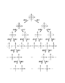
【0030】
図3は、図2のQAM変調器206において実行される32QAM信号セットの極めて詳細な分割例を示している。その図は、与えられた変調シンボル発生間隔ごとに変調器に供給されるm=5の入力ビットの値に基づいて、与えられたシンボル又は型の点が選択される方法を示している。その図形において、5つの入力ビットはd0,d1,d2,d3及びd4の記号で表されている。最低ビットd0は、32QAM点の2つのサブセットの1つを選択するのに用いられ、残りのビットd1,d2,d3及びd4はそれらの親のセットから適当なサブセットを選択するのに用いられる。
【0031】
受信されたQAMシンボルの復号化は次の方法で実行される。最初に、最低レベルが符号RS1に対応するRS復号器を用いて復号され、その結果、訂正されたシーケンスは次に高いレベルの復号化に使用される。その復号化はすべてのレベルの復号が完了するまで連続して繰り返される。
【0032】
図2の実施形態の多くの異なる具体例が可能である。例えば、(60,12)RS符号、(60,50)RS符号及び(60,58)RS符号にそれぞれ対応するRS1符号、RS2符号、及びRS3符号をもつGF(26)のRS符号を用いて実施形態を実現できる。別の例としては、(100,16)RS符号、(100,86)RS符号及び(100,98)RS符号にそれぞれ対応するRS1符号、RS2符号、及びRS3符号をもつGF(28)のRS符号を用いて実施形態を具体化できる。
【0033】
これらの具体例はともに、符号化されない16QAMに関して大きな符号利得を可能にする。さらに詳しくは、10-5のビットエラーレート(BER)において、上記したGF(26)符号は約2.3dBの利得を可能にし、上記したGF(28)符号は約2.5dBの利得を可能にすることがシュミレーションで分かっている。多くの他の具体例も可能であることは言うまでもない。
【0034】
一般には、図2の実施形態における適切な符号レートは次のように選択される。全部でm=5のレベルの場合には、5個のレベルのうち最低レベルは約0.2から0.3までの範囲にほぼ符号レートを持つように形成される。5個のレベルのうち次に高いレベルは約0.8から0.9までの範囲にほぼ符号レートを持つように形成される。5個のレベルのうち次に高いレベルは約0.9よりも大きい範囲に符号レートを持つように形成される。1.0の符号レートは無符号化、例えば、図2の実施形態におけるQAM変調器に直接渡されるレベルに対応する。したがって、約0.9よりも大きい符号レートを持つレベルは符号化されないレベルである。
【0035】
全部でm=4のレベルの実施形態の場合には、4つのレベルのうち最低レベルは約0.2から0.3までの範囲にほぼ符号レートを持つように形成される。4個のレベルのうち次に高い2つのレベルは約0.9及び0.95の範囲にそれぞれ符号レートを持つように形成される。さらに、符号化されないレベルは1.0の符号レートを持ち、同じく約0.9又は0.95より大きい符号レートを持つレベルも符号化されない。
【0036】
図4は、本発明の第2の実施形態による通信システム400の送信部の概略ブロック図である。この実施形態は本発明による多重レベル連結符号化の例であり、その中では、与えられたレベルセットの中の指定されたサブセットの各レベルに異なるRS符号が適用される。また、最低レベルのうち1つ又はそれ以上におけるRS符号は重畳符号と連結される。
【0037】
この場合の実施形態においては、最低レベルにおけるRS符号だけが重畳符号と連結される。図に示す通信システム400の部分は、符号器404、32QAM変調器406、及び付加的なノイズチャネル408を備えている。さらに、m=5の値が説明の都合上選択されているが、他の値でも可能である。
【0038】
符号器404及びQAM変調器406の構成は、図2の実施形態に関連して記載されたものと実質的に同じである。図2の符号器204と同様に、符号器404は3つのRS符号器要素を有し、この実施形態において410−1,410−2及び410−3で示されている。この3つのRS符号要素は、複数のRS符号であるRS1,RS2及びRS3をそれぞれ3つの最低レベルの入力ビットに適用し、2つの最高レベルの入力ビットは符号化されずに変調器406に渡される。
【0039】
しかしながら、符号器404は符号器要素410−1の出力に結合する入力を持つ重畳符号器412をさらに有する。符号器412によって用いられる重畳符号化は最低レベルに対する内部符号に相当する。一方、RS符号RS1は最低レベルに対する外部符号を提供する。このことによってソフト決定のヴィテルビ復号化を内部符号のために使用でき、これにより割り増しの符号利得を実現する。QAM変調器406におけるQAMシンボルへの入力ビットのマッピングもまた、上記したUngerboeckのセット分割を用いて実行される。
【0040】
図4の実施形態においては、連結されたRS符号及び重畳符号は最低レベルに対してだけに用いられたが、このことは単なる一例にすぎずこれに限定するものではない。さらに一般的には、複数の最低レベルj=1,…jmaxの各々は連結されたRS符号及び重畳符号を持つことができる。ここで、jmaxはimax以下、すなわちRS符号を持つレベル数以下である。
【0041】
図4の実施形態についてのいくつかの具体例を次に説明する。第1の例は、重畳符号器412に関してレート1/2の4状態重畳符号を用い、RS1符号、RS2符号及びRS3符号を持つGF(28)のRS符号は、それぞれ(50,16)RS符号、(100,86)RS符号及び(100,98)RS符号に対応している。第2の例は、同じくレート1/2の4状態重畳符号を用いているが、RS1符号、RS2符号及びRS3符号を持つGF(28)のRS符号は、それぞれ(50,28)RS符号、(100,74)RS符号及び(100,98)RS符号に対応している。
【0042】
これら2つの具体例はともに符号化されない16QAMと比較して大きな符号利得を可能にする。さらに詳しくは、10-5のビットエラーレート(BER)において、上記した第1の例ではGF(26)符号は約2.6dBの利得を可能にし、上記した第2の例ではGF(28)符号は約3.4dBの利得を可能にすることがシュミレーションで分かっている。さらに他の多くの具体例も可能であることは言うまでもない。
【0043】
図4の実施形態の他の具体例の1つは、m=5ではあるが最低レベルは2つだけで、連結されたRS符号及び重畳符号を用いた最低レベルである。RS符号はGF(25)で、そのRS1符号及びRS2符号が、それぞれ(15,6)RS符号及び(30,24)RS符号に対応している。この具体例においてはRS3符号は使用されず、対応するレベルは符号化されずに変調器に渡される。この具体例では、16QAMと比較して、10-5のBERにおいて約2.5dBの利得を可能にすることがシュミレーションで分かっている。
【0044】
図4の関連する上記のいくつかの実施形態は、高いレートの符号化、例えば全体的にほぼ0.8程度の符号レートが要求される制限された帯域幅のチャネルについての決定に基づいており、重畳符号は最低レベルのビットだけに適用することが望ましい。しかしながら、前に述べたように、連結されたRS−重畳符号は1つ又はそれ以上の追加のレベルに対しても最低レベルと同様に使用することができる。
【0045】
符号器412における重畳符号の複雑さが増加しても、性能が顕著に改善するものではないことがシュミレーションで分かっている。したがって、アプリケーションにおいては符号の複雑性を最小にすることが望ましく、上記した4状態符号は、さらに大きな状態数、例えば16,64又は256状態を持つ重畳符号よりも好ましい。
【0046】
多重レベルの符号器−変調器の対である図2の204−206及び図4の404−406は、上記の例におけるように符号利得に対して共同で最適化するのと同様に又はそれに代わって、ソース内容に対して共同で最適化できることは注目に値する。
【0047】
図5は、図4の実施形態が不等エラー保護を実現するのに利用できる方法を示している。この図において、ソース符号化されたビットの与えられたフレーム500は、ビットの4つの異なるクラス、すなわちクラスI、クラスII、クラスIII及びクラスIVを有し、それぞれ502−1,502−2,502−3及び502−4で示されている。
【0048】
ビットの異なるクラスは情報の異なるレベルを持っている。すなわち、クラスIビットはフレーム500で重要度が最も高いビットであり、クラスIVビットはフレーム500で重要度が最も小さいビットである。クラスIビットは、符号器要素410−1及び重畳符号器412によって可能となる連結されたRS−重畳符号を用いて符号化される。クラスIIビット及びクラスIIIビットは、それぞれRS符号器要素410−2及び410−3を用いて符号化される。多重レベル符号化処理における最高の2つのレベルであるクラスIVは、符号化されずにQAM変調器406に渡される。
【0049】
符号器要素410−1において使用されるRS1符号は指定されて、クラスIビットがすべての他のレベルのビットよりも大きな量のエラー保護を有するのを保証する。同様に、符号器410−2において使用されるRS2符号は指定されて、クラスIIビットがクラスIIIビットよりも大きな量のエラー保護を有するのを保証し、符号器410−3において使用されるRS3符号は指定されて、クラスIIIビットがクラスIVビットよりも大きな量のエラー保護を有するのを保証する。
【0050】
図5に示した不等エラー保護配列の大きな利点は、各クラスI、II及びIIIが異なる検出能力のエラーフラグを持つことが可能なことであり、これによりソース復号器においてエラー緩和やエラー隠蔽を容易にできる。
【0051】
図6は、ソース符号化フレーム500について不等エラー保護を実行する本発明の他の実施形態を示している。この実施形態においては、符号器要素410−1,410−2及び410−3並びにQAM変調器406を備え、最高のレベルが低いレベルよりも高い信頼性をもつように多重レベル符号が形成される。
【0052】
これは使用される特定の多重レベル符号の特徴であり、符号器要素410−1,410−2及び410−3のそれぞれにおいて使用されるRS1符号、RS2符号及びRS3符号のレートは、この特徴を満足するために固定することができる。
【0053】
したがって、重要度が最も低いビット、すなわちクラスIVビットは2つの最低レベルにマップされ、RS1符号及びRS2符号を用いて処理される。クラスIIIビットはRS3符号を用いて処理される。重要度が最も高いビット、すなわちクラスIビット及びクラスIIビットはそれぞれ巡回冗長検査(CRC)符号器602及び604を用いて符号化される。
【0054】
この配列は、エラーフラグをクラスIビット及びクラスIIビットのために発生して、ソース復号器におけるエラー緩和及びエラー隠蔽のために使用することができる。RS1符号、RS2符号及びRS3符号は、ビットの他のクラスのためにエラーフラグを発生することができる。CRC符号器602及び604の外形が点線で示されているのは、クラスIビット及びクラスIIビットに対してエラーフラグが要求されない場合にはこのような符号器は削除できるからである。
【0055】
図5及び図6に示した配列は単なる例にすぎない。別の構成においては、図5及び図6において点線の外形で示した重畳符号器412は削除することができる。その結果、不等エラー保護は、実質的に図2の実施形態のような連結されていない多重レベル符号化を用いて実現される。
【0056】
さらに、ビットの複数のクラスの特定の数、タイプ及び他の性質は、一般的に特定の符号化アプリケーションに依存して変化することになる。ビットの複数のクラスを多重レベル符号化のレベルにマッピングする技術もまた、各クラスによって要求されるエラー検出の量及びエラー訂正能力に依存することになる。
【0057】
図7は、本発明の多重レベル符号化技術を通信システムにおける時間ダイバシティを実現するために使用する方法を示している。この実施形態においては、1セットのソースフレーム700は、フレーム1,フレーム2,フレーム3,フレーム4及びフレーム5の5個のフレームを含み、それぞれ702−1,702−2,702−3,702−4及び702−5で示されている。
【0058】
時間ダイバシティは、送信チャネルにおいて発生するエラーのバーストの影響を軽減するために望ましいことである。例えば、図5及び図6の実施形態において、エラーのバーストが発生した場合には、受信するフレーム500全体がエラーだらけになってしまう。フレームサイズが大きい場合にはこのようなエラーバーストは問題となり、ソース復号器はエラー緩和又はエラー隠蔽ができなくなる。
【0059】
時間ダイバシティを実現することによって、与えられるエラーバーストの影響が多くのフレームに分散される。図7の場合には、フレーム702−1,702−2,702−3,702−4及び702−5を本発明の多重レベル符号の異なるレベルにマッピングすることによってこのことが遂行される。
【0060】
フレーム702−1はフレーム700の中で最も短く、フレーム702−2がそれに続いて次に長さが短いフレームである。一方、フレーム702−3,702−4及び702−5は長いフレームである。多重レベル符号における異なる符号化レベルは、通常はそれに関係する異なる符号レートを持っているので、各符号化レベルは固定した数の送信シンボルについて異なる情報ビットの量を搬送する。したがって、少ないビットを持つソース符号化されたフレームは低いレベルで送信でき、大きいフレームは高いレベルで送信できる。
【0061】
さらに詳しくは、この実施形態における多重レベル符号は、例えば図4の符号器404及び変調器406に相当する多重レベル連結符号器710を用いて具体化される。最も短いフレーム702−1は最低レベルにマップされ、次に短いフレーム702−2は次に高いレベルにマップされ、それより長いフレーム702−3,702−4及び702−5は次に高いレベルにマップされる。多重レベルの連結された符号器710の動作は、図4に関連して前に述べたものと同じである。他の実施形態においては、図2において示したような多重レベルの連結されない符号器が使用される。
【0062】
図7において説明した方法で時間ダイバシティを実現ことは、異なるソース符号化フレームが送信の前に多重化されるので、追加の遅延を持ち込むことになる。しかしながら、IBOC−AM及びIBOC−FMのようなDABシステムにおいては、この追加の遅延は一般的に問題にならない。
【0063】
本発明の実施形態においては、図5及び図6において説明した不等エラー保護の技術は、図7において説明した時間ダイバシティの技術と合成することが可能である。例えば、図7における1セットのフレーム700のフレーム702の各々は、図5及び図6に示したように、異なる複数のクラスに分割することができる。フレーム702の各々からのクラスIビットは、最大量のエラー保護を実現するレベルに多重化することができる。同様に、フレーム702の各々からのクラスIVビットは、最小量のエラー保護を実現するレベルに多重化することができる。ビットの中間のクラスも同様に、適当なレベルに多重化することができる。
【0064】
前に述べたように、ここに記載された多重レベル符号化の実施形態は、通信システムにおいて共通に使用される付加的な要素を含むことができる。すなわち、インターリーブ及びデインターリーブ、アップコンバータ及びダウンコンバータ、フィルタ処理、増幅等を含むことができる。
【0065】
当業者は、ここに記載された多重レベル符号化技術が与えられた場合、受信した多重レベル符号化シンボルを複合化するための相補的動作を実行する能力の受信機要素の適切な配列を簡単な方法で構成することができる。このような受信機要素の一例を次に述べる。
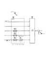
【0066】
図8は、本発明による通信システムの受信部800の一例を示している。受信部800は、図2の通信システム200又は図4の通信システム400において使用することができる。図に示す受信部800は、QAM復調器802、多重レベル復号器804、及びパラレル/シリアル・コンバータ806を備えている。
【0067】
チャネル208又は408から受信した入力QAMシンボルは、QAM復調器802において復調され、その結果、出力は復号器804に供給される。2つの最高レベルに対応するビットはパラレル/シリアル・コンバータ806に直接渡される。3つの最低レベルのビットはRS復号器要素810−1,810−2及び810−3においてそれぞれ処理される。
【0068】
これらの復号器要素810−1,810−2及び810−3は、それぞれ、図2のRS符号器要素210−1,210−2及び210−3又は図4のRS符号器要素410−1,410−2及び410−3において実行された符号化動作に対する相補的な復号化動作を実行する。多重レベル符号器804において、復号器要素810−1の出力は復号器810−2及び810−3にも供給され、復号器要素810−2の出力は復号器810−3にも供給される。
【0069】
多重レベル符号器804の最低レベルは、図4の重畳符号器412の重畳符号を復号するのに使用されるヴィテルビ復号器812をさらに有する。ヴィテルビ復号器812が点線の外形で示されているのは、受信部800が図2の送信部と一緒に使用される場合には、このヴィテルビ復号器812は使用されないからである。
【0070】
図2及び図4〜図8に示した実施形態は、従来のハードウェア処理及びそれに関連するソフトウェア要素を用いて具体化される。このようなハードウェア処理は、最適にプログラムされたマイクロプロセッサ、ディジタル・シグナル・プロセッサ(DSP)、特定用途向け集積回路(ASIC)、又はこれらの一部若しくは組み合わせ、及び他のよく知られたデバイスを備えている。本発明は、上記の1つ又はそれ以上のデバイスに結合されたメモリ内にストアされるソフトウェアの少なくとも一部において具体化することができる。
【0071】
本発明は、IBOC−AM又はIBOC−FMシステムの制限された帯域幅の通信チャネルで送信するために、例えばPAC符号器のようなオーディオ符号器によって発生される圧縮オーディオビットのように、ソース符号化情報ビットの高速レートチャネル符号化に関連する用途に対して、特によく適した多重レベル符号化技術を提供する。
【0072】
本発明の多重レベル符号化技術は、ソース符号化音声情報、イメージ情報又はビデオ情報等の多くの他のタイプに適用できることはもちろんである。さらに、本発明は、実施形態において使用されたRS符号、従来の符号及びCRC符号とは異なる他の符号を用いて具体化することができる。例えば、RS符号はよく知られた他のタイプのブロック符号に置き換えることが可能であり、従来の符号はターボ符号に置き換えることが可能である。
【0073】
さらにまた、本発明は極めて多様な異なるタイプの通信システムアプリケーションに利用することができる。その通信システムには、インターネット及び他のコンピュータネットワークでの通信、並びに、移動体通信マルチメディア、衛星、無線ケーブル、無線ローカルループ、高速無線接続、及び他のタイプの通信が含まれる。
【0074】
本発明はあらゆるタイプの通信チャネルとともに利用することができる。例えば、周波数チャネル、タイムスロット、符号分割多元接続(CDMA)スロット、非同期転送モード(ATM)若しくは他のパケットベースの伝送システムにおける仮想接続とともに利用することができる。
【0075】
特許請求の範囲に記載した発明の構成要件の後に括弧付きの符号がある場合は、構成要件と実施例と対応づけて発明を容易に理解させる為のものであり、特許請求の範囲の解釈に用いるべきのものではない。
【図面の簡単な説明】
【図1】従来の通信システムの送信部の簡単なブロック図。
【図2】本発明の実施形態による通信システムの送信部の簡単なブロック図。
【図3】図2の実施形態のQAM変調において実行される32QAM信号セットの分割を示す図。
【図4】本発明の実施形態における通信システムの送信部の簡単なブロック図。
【図5】本発明の実施形態における通信システムの送信部の簡単なブロック図
【図6】本発明の実施形態における通信システムの送信部の簡単なブロック図
【図7】本発明の実施形態における通信システムの送信部の簡単なブロック図
【図8】図2及び図4の送信部の用途に適した通信システムの受信部の簡単なブロック図。
【符号の説明】
102 オーディオ符号器
104 ブロック符号器
108 チャネル
106 変調器
204,404 符号器
206,406 変調器
208,408 チャネル
210,410 リードソロモン(RS)符号要素
412 重畳符号要素
500,700,702 フレーム
502 クラス
602 巡回冗長検査(CRC)符号要素
710 多重レベル結合符号器
802 復調器
804 復号器
806 パラレル/シリアル・コンバータ
810 リードソロモン(RS)復号要素
812 ヴィテルビ復号器[0001]
BACKGROUND OF THE INVENTION
The present invention generally relates to a multilevel encoding method and multilevel decoding method in a communication system, a multilevel encoding apparatus in a communication system, and an apparatus storing software of a multilevel encoding method in a communication system. In particular, the present invention relates to a multi-level encoding method in a digital audio broadcasting (DAB) system and other communication systems.
[0002]
[Prior art]
A hybrid in-band on-channel (IBOC) DAB system has been developed that broadcasts digital audio signals in the AM band along with analog amplitude modulation (AM) programs. Such a system is also called an IBOC-AM system. In such systems, the power and bandwidth allocated for digital audio transmission are both very limited.
[0003]
As a result, these systems typically cannot add sufficient redundancy for error control using conventional superimposed coding techniques. However, it is well known that the quality of the decoded audio can be improved by using error mitigation and error concealment algorithms in the audio decoder.
[0004]
In order to efficiently use such an error mitigation and error concealment algorithm, an error flag indicating the quality of the bit stream, which is the decoded bit stream of the channel, is generally required. Such an error flag can be generated using a block code such as a Reed-Solomon (RS) code.
[0005]
FIG. 1 shows a simple block diagram of a transmission unit of a conventional IBOC-
[0006]
The RS code symbols output from
[0007]
In the system as shown in FIG. 1, the conventional technique for directly mapping the RS code symbol to the QAM symbol is usually a modulation of 2m-Galois field GF in the case of QAM (2m) Based RS code is necessary. Thus, each m-bit symbol can be directly mapped to an m-bit QAM symbol. However, this limits the selection of applicable RS codes to one and thus affects the error correction capability.
[0008]
For example, when 32-QAM modulation is used, the fully mapped RS code is GF (2Five). Given a coding rate of 0.8, an RS code of (30, 24) is applied for the map. As a result, a 5-bit RS code symbol is mapped to a 5-bit QAM symbol.
[0009]
Longer block codes provide stronger error protection, so GF (26It is desirable to use (60,48) RS codes based on This is because many random errors can be corrected twice in the same manner as the (30, 24) RS code. However, this results in a mismatch between the 6-bit RS code symbol and the 5-bit QAM symbol.
[0010]
Multilevel encoding is well known as a technique for solving such a mismatch problem. As an alternative to applying RS codes or other block codes to data bits and consequently mapping code symbols as shown in FIG. 1 to m-bit modulation symbols, multi-level coding is a modulation technique for coalescing coding. For each bit of a given m-bit modulation symbol, a single or superimposed code with a different appropriate rate is applied.
[0011]
As an example of multilevel coding, a report on IEEE information theory in January 1997, Vol. 35, no. 1, 87-98. J. et al. Pottie and D.C. P. “Multi-level coding based on division” by Taylor, report on IEEE information theory in March 1997, Vol. IT-23, no. 3, 371-377. Imai and S.M. “New multi-level encoding method using error correction code” by Hirakawa, and Computer Science Vol. In the spring of 1355, E.C. is a lecture note on the encryption method and encoding on pages 143-154. Hunsi and P.M. There is “strongly Reed-Solomon encoded MPSK modulation” by Sweeney.
[0012]
The last reference describes a technique using an RS code as an element code for multilevel coding combined with M-array phase shift keying (MPSK) modulation instead of QAM modulation.
[0013]
[Problems to be solved by the invention]
A major problem with the multi-level coding techniques described in the above listed references is that they achieve optimal performance in IBOC-AM DAB systems and other communication system applications with limited bandwidth. It is impossible. For this reason, improvement of the multilevel encoding technique is desired.
[0014]
[Means for Solving the Problems]
The present invention provides an improved technique for multilevel coding in a communication system.
In accordance with the present invention, a series of source-encoded information bits are divided into a plurality of parts, each part being associated with a different level of multilevel encoding. At least one code is specified in the entire set of levels so that the portion of the information bits corresponding to the level in the specified subset is encoded, while the portion of the information bits corresponding to the unspecified subset is not encoded. Applied to the part of each level of information bits in the subset.
[0015]
Codes applied to a given level include block codes such as Reed-Solomon (RS) codes, RS codes concatenated with superposition codes, or other suitable single or concatenated codes. Both the coded portion of the information bits and the uncoded portion of the information bits are used to select modulation symbols for transmission in the system. For example, as shown in the embodiment of the present invention, when there are a total of m levels and a number of levels smaller than m are encoded, 2mA modulation symbol is selected from the modulation type signal set.
[0016]
According to the present invention, m levels from the lowest level to the highest level are arranged, and the specified subset of levels includes at least the lowest level. In particular, the specified subset is a contiguous series of i starting at the lowest level.maxHave Where im axIs a number greater than or equal to 1 and less than m.
[0017]
The portion of the information bits for each level of the designated subset has at least one block code applied thereto. A series of adjacent i starting at the lowest levelmaxThe block code applied to the part of the information bits for is selected, so that a series of adjacent imaxThe code rate increases from the lowest code rate for the block code associated with the lowest level to the highest code rate for the block code associated with the highest level.
[0018]
According to the present invention, the lowest level j = 1,.maxEach has a block code concatenated with the superposition code. Where jmaxIs 1 or more and imaxIt is as follows.
The multi-level coding technique of the present invention has the advantage of achieving a large code gain and thus improving the performance with respect to bit error rate (BER) over the prior art. Furthermore, the multi-level encoding technique of the present invention can be used to meet unequal error protection and time diversity. Furthermore, by using block codes, the present invention ensures that the error flag is valid for error mitigation and error concealment in the source demodulator.
[0019]
The present invention can be applied to any type of digital information including, for example, audio, conversation, video and image information and various combinations thereof. Further, the present invention can be implemented in many communication systems including AM and FM IBOC DAB systems, the Internet, and satellite broadcasting systems.
[0020]
DETAILED DESCRIPTION OF THE INVENTION
In this embodiment, the present invention will be described by taking as an example a communication system well suited for a hybrid in-band on-channel (IBOC) communication system operating in the AM band. However, it goes without saying that the present invention is generally applicable to any communication system application as long as the multilevel coding technique can be effectively applied. For example, the present invention can be applied to a hybrid IBOC system operating in the FM band, an all-digital DAB system, an Internet-based and satellite-based broadcasting system, and the like.
[0021]
FIG. 2 is a schematic block diagram of a transmission unit of the
[0022]
While the embodiment of FIG. 2 and other embodiments described below utilize a 32QAM modulator, this is merely an example. Any type of modulation that can be used in conjunction with the multilevel encoding techniques described herein, eg, 2mEven those using QAM or M-array phase shift keying (MPSK) modulation are generally applicable. In the embodiments described herein, 2mSpecific examples with QAM are shown, in which 5 is selected as the value of m for simplicity of explanation, but the value of m is not limited to a specific value.
[0023]
[0024]
In accordance with the present invention, each designated subset of m bits corresponds to an RS code that begins with the lowest level bit and is applied thereto at encoder element 210i. Where i = 1,..., ImaxAnd imaxIs 1 or more and less than m. For example, in the embodiment shown in FIG. 2, m is 5 and imaxIs 3. In this case, there are a total of five levels, of which two levels are unencoded levels and three levels are encoded levels.
[0025]
In another embodiment, m is 5 and imaxIs 2. In this case, there are a total of five levels, of which three levels are unencoded levels and two levels are encoded levels. Or imaxIs 4. In this case, there are five levels in total, one of which is an unencoded level and four of which are encoded levels.
[0026]
In yet another embodiment, m is 4 and 16QAM modulation is used, and imaxIs 2. In this case, there are a total of four levels, of which two levels are unencoded levels and two levels are encoded levels. Alternatively, in the embodiment where m = 4, imaxIs 3. In this case, there are four levels in total, one of which is a level that is not encoded, and three levels that are encoded.
[0027]
In the embodiment of FIG. 1, m = 5, imax= 3, in the first encoder element 210-1, the first RS code RS1 is supplied with the lowest level bit or
[0028]
The 32QAM modulator 206 receives m = 5, which is the output of the
[0029]
The mapping of input bits to QAM symbols in the
[0030]
FIG. 3 shows a very detailed partitioning example of the 32QAM signal set implemented in the QAM modulator 206 of FIG. The figure shows how a given symbol or type point is selected based on the value of m = 5 input bits supplied to the modulator at every given modulation symbol generation interval. In that figure, the five input bits are d0, D1, D2, DThreeAnd dFourIt is represented by the symbol. Lowest bit d0Is used to select one of the two subsets of 32QAM points and the remaining bits d1, D2, DThreeAnd dFourIs used to select an appropriate subset from their parent set.
[0031]
Decoding of received QAM symbols is performed in the following manner. First, the lowest level is decoded using an RS decoder corresponding to the code RS1, so that the corrected sequence is used for the next higher level decoding. The decoding is repeated continuously until all levels of decoding are complete.
[0032]
Many different implementations of the embodiment of FIG. 2 are possible. For example, GF (2 having RS1, RS2, and RS3 codes corresponding to (60,12) RS code, (60,50) RS code, and (60,58) RS code, respectively.6The embodiment can be realized using the RS code. As another example, GF (2 having RS1 code, RS2 code, and RS3 code respectively corresponding to (100, 16) RS code, (100, 86) RS code, and (100, 98) RS code.8The embodiment can be embodied by using the RS code.
[0033]
Both of these implementations allow a large code gain for unencoded 16QAM. More specifically, 10-FiveAt the bit error rate (BER) of GF (26) Code allows a gain of about 2.3 dB, and the GF (28The simulation shows that the code allows a gain of about 2.5 dB. It goes without saying that many other embodiments are possible.
[0034]
In general, the appropriate code rate in the embodiment of FIG. 2 is selected as follows. In the case of a total of m = 5 levels, the lowest level among the five levels is formed to have a code rate in the range of about 0.2 to 0.3. The next highest level among the five levels is formed to have a code rate in the range of about 0.8 to 0.9. The next higher level among the five levels is formed to have a code rate in a range greater than about 0.9. A code rate of 1.0 corresponds to unencoded, eg, a level passed directly to the QAM modulator in the embodiment of FIG. Therefore, a level having a code rate greater than about 0.9 is an uncoded level.
[0035]
For an embodiment with a total of m = 4 levels, the lowest of the four levels is formed to have a code rate approximately in the range of about 0.2 to 0.3. The next two of the four levels are formed to have code rates in the range of about 0.9 and 0.95, respectively. Furthermore, uncoded levels have a code rate of 1.0, and levels with a code rate that is also greater than about 0.9 or 0.95 are not coded.
[0036]
FIG. 4 is a schematic block diagram of a transmission unit of the
[0037]
In the embodiment in this case, only the RS code at the lowest level is concatenated with the superimposed code. The portion of the
[0038]
The configuration of
[0039]
However,
[0040]
In the embodiment of FIG. 4, the concatenated RS code and superposition code are used only for the lowest level, but this is only an example and is not limited thereto. More generally, a plurality of lowest levels j = 1,.maxEach may have a concatenated RS code and a superposition code. Where jmaxImaxBelow, that is, below the number of levels with RS code.
[0041]
Some specific examples of the embodiment of FIG. 4 will now be described. The first example uses a rate ½ 4-state superposition code for
[0042]
Both these two examples allow a large code gain compared to unencoded 16QAM. More specifically, 10-FiveIn the bit error rate (BER) of GF (26) Code allows a gain of about 2.6 dB, and in the second example above, GF (28The simulation shows that the code allows a gain of about 3.4 dB. Of course, many other embodiments are possible.
[0043]
Another specific example of the embodiment of FIG. 4 is m = 5, but only two lowest levels, which are the lowest levels using concatenated RS codes and superposition codes. RS code is GF (2Five), The RS1 code and the RS2 code correspond to the (15, 6) RS code and the (30, 24) RS code, respectively. In this example, no RS3 code is used and the corresponding level is passed to the modulator without being encoded. In this example, it is 10 compared to 16QAM.-FiveSimulations have shown that a gain of about 2.5 dB is possible at a BER of.
[0044]
Some of the above related embodiments of FIG. 4 are based on a decision for a high bandwidth encoding, for example a limited bandwidth channel where an overall code rate of around 0.8 is required. The superimposition code is preferably applied only to the lowest level bits. However, as previously mentioned, concatenated RS-superimposed codes can be used for one or more additional levels as well as the lowest level.
[0045]
Simulations have shown that the performance does not improve significantly even if the complexity of the superposition code in
[0046]
The multi-level encoder-modulator pair 204-206 in FIG. 2 and 404-406 in FIG. 4 are similar to or alternative to joint optimization for code gain as in the above example. It is worth noting that the source content can be jointly optimized.
[0047]
FIG. 5 illustrates how the embodiment of FIG. 4 can be used to implement unequal error protection. In this figure, a given
[0048]
Different classes of bits have different levels of information. That is, the class I bit has the highest importance in the
[0049]
The RS1 code used in encoder element 410-1 is specified to ensure that class I bits have a greater amount of error protection than all other levels of bits. Similarly, the RS2 code used in encoder 410-2 is specified to ensure that class II bits have a greater amount of error protection than class III bits, and RS3 code used in encoder 410-3. A code is specified to ensure that class III bits have a greater amount of error protection than class IV bits.
[0050]
A significant advantage of the unequal error protection arrangement shown in FIG. 5 is that each class I, II, and III can have error flags with different detection capabilities, which allows error mitigation and error concealment in the source decoder. Can be easily done.
[0051]
FIG. 6 illustrates another embodiment of the present invention that performs unequal error protection for a source encoded
[0052]
This is a feature of the particular multilevel code used, and the rate of the RS1, RS2 and RS3 codes used in each of the encoder elements 410-1, 410-2 and 410-3 is determined by this feature. Can be fixed to be satisfied.
[0053]
Thus, the least significant bits, ie class IV bits, are mapped to the two lowest levels and processed using RS1 and RS2 codes. Class III bits are processed using RS3 codes. The most important bits, ie, class I bits and class II bits, are encoded using cyclic redundancy check (CRC)
[0054]
This arrangement can generate error flags for class I and class II bits and can be used for error mitigation and error concealment in the source decoder. The RS1, RS2 and RS3 codes can generate error flags for other classes of bits. The outlines of the
[0055]
The arrangements shown in FIGS. 5 and 6 are merely examples. In another configuration, the
[0056]
Furthermore, the specific number, type and other properties of the multiple classes of bits will generally vary depending on the particular encoding application. The technique of mapping multiple classes of bits to the level of multi-level coding will also depend on the amount of error detection required by each class and the error correction capability.
[0057]
FIG. 7 illustrates a method of using the multi-level encoding technique of the present invention to achieve time diversity in a communication system. In this embodiment, a set of source frames 700 includes five frames,
[0058]
Time diversity is desirable to reduce the effects of bursts of errors that occur in the transmission channel. For example, in the embodiment of FIGS. 5 and 6, when a burst of errors occurs, the entire received
[0059]
By realizing time diversity, the effect of a given error burst is distributed over many frames. In the case of FIG. 7, this is accomplished by mapping frames 702-1, 702-2, 702-3, 702-4 and 702-5 to different levels of the multilevel code of the present invention.
[0060]
The frame 702-1 is the shortest frame 700, and the frame 702-2 is the next shortest frame. On the other hand, the frames 702-3, 702-4, and 702-5 are long frames. Since different coding levels in a multi-level code usually have different code rates associated with it, each coding level carries a different amount of information bits for a fixed number of transmission symbols. Thus, source encoded frames with fewer bits can be transmitted at a lower level and larger frames can be transmitted at a higher level.
[0061]
More specifically, the multilevel code in this embodiment is implemented using, for example, a multilevel concatenated
[0062]
Implementing time diversity in the manner described in FIG. 7 introduces additional delay because different source encoded frames are multiplexed before transmission. However, in DAB systems such as IBOC-AM and IBOC-FM, this additional delay is generally not a problem.
[0063]
In the embodiment of the present invention, the unequal error protection technique described in FIGS. 5 and 6 can be combined with the time diversity technique described in FIG. For example, each of the frames 702 of the set of frames 700 in FIG. 7 can be divided into different classes as shown in FIGS. Class I bits from each of the frames 702 can be multiplexed to a level that provides the maximum amount of error protection. Similarly, class IV bits from each of the frames 702 can be multiplexed to a level that provides a minimum amount of error protection. The middle class of bits can be multiplexed to the appropriate level as well.
[0064]
As previously mentioned, the multi-level encoding embodiments described herein can include additional elements commonly used in communication systems. That is, interleaving and deinterleaving, up-converter and down-converter, filtering, amplification, etc. can be included.
[0065]
One of ordinary skill in the art can easily simplify the appropriate arrangement of receiver elements with the ability to perform complementary operations to decode received multilevel encoded symbols given the multilevel encoding techniques described herein. Can be configured in various ways. An example of such a receiver element will now be described.
[0066]
FIG. 8 shows an example of the receiving unit 800 of the communication system according to the present invention. The receiving unit 800 can be used in the
[0067]
Input QAM symbols received from
[0068]
These decoder elements 810-1, 810-2 and 810-3 are respectively RS encoder elements 210-1, 210-2 and 210-3 of FIG. 2 or RS encoder elements 410-1, FIG. Perform a decoding operation that is complementary to the encoding operation performed at 410-2 and 410-3. In
[0069]
The lowest level of the
[0070]
The embodiments shown in FIGS. 2 and 4-8 are implemented using conventional hardware processing and associated software elements. Such hardware processing includes optimally programmed microprocessors, digital signal processors (DSPs), application specific integrated circuits (ASICs), or parts or combinations thereof, and other well-known devices. It has. The present invention may be embodied in at least a portion of software stored in memory coupled to one or more of the devices described above.
[0071]
The present invention relates to a source code, such as a compressed audio bit generated by an audio encoder, such as a PAC encoder, for transmission on a limited bandwidth communication channel of an IBOC-AM or IBOC-FM system. A multilevel coding technique is provided that is particularly well suited for applications related to fast rate channel coding of coded information bits.
[0072]
Of course, the multi-level encoding technique of the present invention can be applied to many other types such as source encoded audio information, image information or video information. Furthermore, the present invention can be embodied using other codes different from the RS code, the conventional code, and the CRC code used in the embodiment. For example, RS codes can be replaced with other well-known types of block codes, and conventional codes can be replaced with turbo codes.
[0073]
Furthermore, the present invention can be utilized in a wide variety of different types of communication system applications. Such communication systems include communications over the Internet and other computer networks, as well as mobile communications multimedia, satellite, wireless cables, wireless local loops, high speed wireless connections, and other types of communications.
[0074]
The present invention can be utilized with any type of communication channel. For example, it can be utilized with virtual channels in frequency channels, time slots, code division multiple access (CDMA) slots, asynchronous transfer mode (ATM) or other packet-based transmission systems.
[0075]
If there is a symbol in parentheses after the constituent features of the invention described in the claims, this is to make the invention easy to understand by associating the constituent requirements with the embodiments, and in interpreting the claims. It should not be used.
[Brief description of the drawings]
FIG. 1 is a simple block diagram of a transmission unit of a conventional communication system.
FIG. 2 is a simple block diagram of a transmission unit of a communication system according to an embodiment of the present invention.
FIG. 3 is a diagram illustrating a division of a 32QAM signal set performed in the QAM modulation of the embodiment of FIG. 2;
FIG. 4 is a simple block diagram of a transmission unit of a communication system in an embodiment of the present invention.
FIG. 5 is a simple block diagram of a transmission unit of a communication system in an embodiment of the present invention.
FIG. 6 is a simple block diagram of a transmission unit of a communication system in an embodiment of the present invention.
FIG. 7 is a simple block diagram of a transmission unit of a communication system in an embodiment of the present invention.
8 is a simple block diagram of a receiving unit of a communication system suitable for the use of the transmitting unit of FIGS. 2 and 4. FIG.
[Explanation of symbols]
102 Audio encoder
104 block encoder
108 channels
106 Modulator
204,404 encoder
206,406 Modulator
208,408 channels
210,410 Reed-Solomon (RS) code element
412 Superimposed code element
500,700,702 frames
502 class
602 Cyclic redundancy check (CRC) code element
710 Multilevel Combined Encoder
802 Demodulator
804 decoder
806 Parallel / Serial Converter
810 Reed-Solomon (RS) decoding element
812 Viterbi decoder
Claims (25)
A)一連の情報ビットを複数の異なる部分に分割するステップと、
B)前記情報ビットの各部分を複数のレベルの1つに関連づけるステップと、
C)前記複数のレベルの指定されたサブセットに含まれる1つ又はそれ以上のレベルに対する前記情報ビットの部分は符号化され、前記指定されたサブセットに含まれない1つ又はそれ以上のレベルに対する前記情報ビットの部分は符号化されないように、前記指定されたサブセットに含まれる各レベルの前記情報ビットの部分に少なくとも1つの符号を適用するステップと、
D)システムにおける送信用の変調シンボルを選択するために前記情報ビットの符号化された部分及び前記情報ビットの符号化されない部分の両方をともに利用するステップとを有し、
前記一連の情報ビットは、複数のフレームの情報ビットを含み、前記複数のフレームの各々は異なるクラスのビットを含み、前記異なるクラスのビットの各々は重要度の異なるレベルを有し、
前記一連の情報ビットの各部分は、時間ダイバシティを提供するように前記複数のフレームの各々の少なくとも一部を含み、指定された量のエラー保護が提供されるように異なるクラスのビットを含む
ことを特徴とする多重レベル符号化方法。A multi-level encoding method for multi-level encoding a series of information bits in a communication system, comprising:
A) dividing a series of information bits into a plurality of different parts;
B) associating each portion of the information bit with one of a plurality of levels;
C) The portion of the information bits for one or more levels included in the specified subset of the plurality of levels is encoded and the one for one or more levels not included in the specified subset Applying at least one code to the portion of the information bits of each level included in the designated subset such that the portion of information bits is not encoded;
D) using both the encoded part of the information bits and the unencoded part of the information bits to select modulation symbols for transmission in the system,
The series of information bits includes information bits of a plurality of frames, each of the plurality of frames includes a different class of bits, and each of the different classes of bits has a different level of importance;
Each portion of the series of information bits includes at least a portion of each of the plurality of frames to provide time diversity and includes a different class of bits to provide a specified amount of error protection. A multilevel encoding method characterized by the above.
前記利用するステップは、2m個の変調型の信号セットの中から、前記m個のレベルのそれぞれと関連するセットのmビットを用いて、1つの前記変調シンボルを選択することを特徴とする請求項1記載の多重レベル符号化方法。The plurality of levels has a total of m levels,
The utilizing step selects one modulation symbol from a set of 2 m modulation signals using m bits of a set associated with each of the m levels. The multi-level encoding method according to claim 1.
B)前記多重レベル符号器の出力に接続された入力を有し、システムにおける送信用の変調シンボルを選択するために符号化された前記情報ビットの部分及び符号化されない前記情報ビットの部分の両方をともに利用する変調器と、
を備え、
前記一連の情報ビットは、複数のフレームの情報ビットを含み、前記複数のフレームの各々は異なるクラスのビットを含み、前記異なるクラスのビットの各々は重要度の異なるレベルを有し、
前記一連の情報ビットの各部分は、時間ダイバシティを提供するように前記複数のフレームの各々の少なくとも一部を含み、指定された量のエラー保護が提供されるように異なるクラスのビットを含む
ことを特徴とする通信システムの多重レベル符号化装置。A) receiving a series of information bits divided into a plurality of different parts, each part corresponding to one of a plurality of levels, for one or more levels included in a specified subset of the plurality of levels The information bit portion is encoded and included in the specified subset to prevent the information bit portion for one or more levels not included in the specified subset from being encoded. A multi-level encoder that operates to apply at least one code to the portion of the information bits of each level;
B) both the portion of the information bits encoded and the portion of the information bits not encoded to select a modulation symbol for transmission in the system, having an input connected to the output of the multilevel encoder A modulator that uses both
With
The series of information bits includes information bits of a plurality of frames, each of the plurality of frames includes a different class of bits, and each of the different classes of bits has a different level of importance;
Each portion of the series of information bits includes at least a portion of each of the plurality of frames to provide time diversity and includes a different class of bits to provide a specified amount of error protection. A multi-level encoding apparatus for a communication system characterized by the above.
前記少なくとも1つのコンピュータプログラムは、
A)各部分が複数のレベルの1つに対応する複数の異なる部分に分割された一連の情報ビットにおいて、前記複数のレベルの指定されたサブセットに含まれる1つ又はそれ以上のレベルに対する前記情報ビットの部分は符号化され、前記指定されたサブセットに含まれない1つ又はそれ以上のレベルに対する前記情報ビットの部分は符号化されないようにするために、前記指定されたサブセットに含まれる各レベルの前記情報ビットの部分に少なくとも1つの符号を適用するステップと、
B)システムにおける送信用の変調シンボルを選択するために符号化された前記情報ビットの部分及び符号化されない前記情報ビットの部分の両方をともに利用するステップと
をコンピュータに実行させ、
前記一連の情報ビットは、複数のフレームの情報ビットを含み、前記複数のフレームの各々は異なるクラスのビットを含み、前記異なるクラスのビットの各々は重要度の異なるレベルを有し、
前記一連の情報ビットの各部分は、時間ダイバシティを提供するように前記複数のフレームの各々の少なくとも一部を含み、指定された量のエラー保護が提供されるように異なるクラスのビットを含む
ことを特徴とする前記少なくとも1つのコンピュータプログラムを記録したコンピュータ読込可能な記録媒体。A computer readable recording medium having recorded thereon at least one computer program used for multi-level encoding a series of information bits in a communication system,
The at least one computer program is
A) The information for one or more levels included in a specified subset of the plurality of levels in a series of information bits, each portion divided into a plurality of different portions corresponding to one of the plurality of levels. Each level included in the specified subset is encoded so that the portion of the information bits for one or more levels not included in the specified subset is encoded. Applying at least one code to the portion of the information bits of
B) causing a computer to use both the portion of the information bits encoded and the portion of the information bits that are not encoded to select a modulation symbol for transmission in the system;
The series of information bits includes information bits of a plurality of frames, each of the plurality of frames includes a different class of bits, and each of the different classes of bits has a different level of importance;
Each portion of the series of information bits includes at least a portion of each of the plurality of frames to provide time diversity and includes a different class of bits to provide a specified amount of error protection. A computer-readable recording medium on which the at least one computer program is recorded.
A)各部分が複数のレベルの1つに対応する複数の異なる部分に分割された一連の情報ビットにおいて、前記複数のレベルの指定されたサブセットに含まれる1つ又はそれ以上のレベルに対する前記情報ビットの部分は符号化され、前記指定されたサブセットに含まれない1つ又はそれ以上のレベルに対する前記情報ビットの部分は符号化されないようにするために、前記指定されたサブセットに含まれる各レベルの前記情報ビットの部分に符号を適用して、符号化された前記情報ビットの部分及び符号化されない前記情報ビットの部分の両方をともに利用することにより選択されて送信された変調シンボルを受信し、前記複数のレベルの各々に対応する出力を得るために受信した前記変調シンボルを復調するステップと、
B)対応する前記情報ビットの部分を得るために前記指定されたサブセットにおいて与えられたレベルに関連する出力を復号化するステップと
を有し、
前記一連の情報ビットは、複数のフレームの情報ビットを含み、前記複数のフレームの各々は異なるクラスのビットを含み、前記異なるクラスのビットの各々は重要度の異なるレベルを有し、
前記一連の情報ビットの各部分は、時間ダイバシティを提供するように前記複数のフレームの各々の少なくとも一部を含み、指定された量のエラー保護が提供されるように異なるクラスのビットを含む
ことを特徴とする多重レベル復号化方法。A multilevel decoding method for decoding a series of information bits that are multilevel encoded in a communication system, comprising:
A) The information for one or more levels included in a specified subset of the plurality of levels in a series of information bits, each portion divided into a plurality of different portions corresponding to one of the plurality of levels. Each level included in the specified subset is encoded so that the portion of the information bits for one or more levels not included in the specified subset is encoded. Receiving a modulation symbol selected and transmitted by applying a code to the information bit portion of the information bit and using both the encoded information bit portion and the uncoded information bit portion together. Demodulating the received modulation symbols to obtain an output corresponding to each of the plurality of levels;
B) decoding an output associated with a given level in the designated subset to obtain a corresponding portion of the information bits;
The series of information bits includes information bits of a plurality of frames, each of the plurality of frames includes a different class of bits, and each of the different classes of bits has a different level of importance;
Each portion of the series of information bits includes at least a portion of each of the plurality of frames to provide time diversity and includes a different class of bits to provide a specified amount of error protection. A multilevel decoding method characterized by:
Applications Claiming Priority (4)
| Application Number | Priority Date | Filing Date | Title |
|---|---|---|---|
| US19550600P | 2000-04-06 | 2000-04-06 | |
| US60/195506 | 2000-04-06 | ||
| US09/765,754 US7190732B2 (en) | 2000-04-06 | 2001-01-19 | Multilevel coding with unequal error protection and time diversity for bandwidth efficient transmission |
| US09/765754 | 2001-01-19 |
Publications (2)
| Publication Number | Publication Date |
|---|---|
| JP2001352357A JP2001352357A (en) | 2001-12-21 |
| JP5153036B2 true JP5153036B2 (en) | 2013-02-27 |
Family
ID=26891032
Family Applications (1)
| Application Number | Title | Priority Date | Filing Date |
|---|---|---|---|
| JP2001106868A Expired - Fee Related JP5153036B2 (en) | 2000-04-06 | 2001-04-05 | Multilevel encoding method and multilevel decoding method in communication system, multilevel encoding apparatus in communication system, and apparatus for storing software of multilevel encoding method in communication system |
Country Status (5)
| Country | Link |
|---|---|
| US (1) | US7190732B2 (en) |
| EP (1) | EP1143653B1 (en) |
| JP (1) | JP5153036B2 (en) |
| CA (1) | CA2337657C (en) |
| DE (1) | DE60142659D1 (en) |
Families Citing this family (26)
| Publication number | Priority date | Publication date | Assignee | Title |
|---|---|---|---|---|
| US6757860B2 (en) * | 2000-08-25 | 2004-06-29 | Agere Systems Inc. | Channel error protection implementable across network layers in a communication system |
| TW519663B (en) * | 2001-05-15 | 2003-02-01 | Via Tech Inc | Memory control device and method |
| US7342938B1 (en) * | 2001-08-06 | 2008-03-11 | Rockwell Collins, Inc. | Spectrally efficient approach to protection of key elements in a non-homogenous data stream |
| US20030099196A1 (en) * | 2001-11-23 | 2003-05-29 | Benoist Sebire | Radio bearer service for IMS services |
| US7778242B1 (en) * | 2001-11-27 | 2010-08-17 | Alcatel Lucent | Protecting content of a packet containing speech data using unequal error protection |
| KR20040083511A (en) * | 2002-02-18 | 2004-10-02 | 코닌클리케 필립스 일렉트로닉스 엔.브이. | Coding a data stream with unequal error protection |
| US7043681B2 (en) * | 2002-05-03 | 2006-05-09 | Ibiquity Digital Corporation | Digital audio broadcasting method and apparatus using complementary pattern-mapped convolutional codes |
| US6970519B2 (en) * | 2003-05-29 | 2005-11-29 | Motorola, Inc. | Method and apparatus to enhance audio quality for digitized voice transmitted over a channel employing frequency diversity |
| US7613985B2 (en) * | 2003-10-24 | 2009-11-03 | Ikanos Communications, Inc. | Hierarchical trellis coded modulation |
| US8209579B2 (en) * | 2004-03-31 | 2012-06-26 | Intel Corporation | Generalized multi-threshold decoder for low-density parity check codes |
| CN101091319B (en) * | 2004-12-29 | 2013-01-02 | 英特尔公司 | Multilevel low density parity-check |
| US8015468B2 (en) * | 2004-12-29 | 2011-09-06 | Intel Corporation | Channel estimation and fixed thresholds for multi-threshold decoding of low-density parity check codes |
| US7856584B2 (en) * | 2005-03-30 | 2010-12-21 | Intel Corporation | Unequal error protection apparatus, systems, and methods |
| US7987415B2 (en) * | 2006-02-15 | 2011-07-26 | Samsung Electronics Co., Ltd. | Method and system for application of unequal error protection to uncompressed video for transmission over wireless channels |
| JP4864535B2 (en) * | 2006-05-16 | 2012-02-01 | 三菱電機株式会社 | Transmission / reception apparatus and transmission / reception method |
| US20080049930A1 (en) * | 2006-08-25 | 2008-02-28 | Samsung Electronics Co., Ltd. | Method and apparatus for encrypting data |
| US7686469B2 (en) | 2006-09-30 | 2010-03-30 | Ruud Lighting, Inc. | LED lighting fixture |
| US7827464B2 (en) * | 2006-11-15 | 2010-11-02 | Seagate Technology Llc | Iterative read channel architectures with coded modulation |
| KR101466695B1 (en) * | 2008-04-30 | 2014-12-01 | 삼성전자주식회사 | Encoding and decoding method of multi bit level data |
| CN102694764B (en) * | 2011-08-17 | 2017-03-15 | 国家新闻出版广电总局广播科学研究院 | Digital audio and video signals method of sending and receiving and device in digital audio broadcast system |
| US20140208102A1 (en) * | 2012-04-27 | 2014-07-24 | Evgeniy Ivanovich Pryakhin | Method of protecting digital information |
| US9595352B2 (en) * | 2014-03-17 | 2017-03-14 | Seagate Technology Llc | Manufacturer self-test for solid-state drives |
| EP3051718B1 (en) * | 2015-01-30 | 2019-12-04 | Casio Computer Co., Ltd. | Information transmission system, symbol stream generating apparatus, symbol stream decoding apparatus, symbol stream generating program, symbol stream decoding program, symbol stream generating method and symbol stream decoding method |
| CN108242972B (en) | 2016-12-26 | 2020-12-15 | 华为技术有限公司 | Method and apparatus for non-orthogonal transmission of data |
| JP2022026454A (en) * | 2020-07-31 | 2022-02-10 | 富士通株式会社 | Communication device and communication system |
| US11770211B2 (en) * | 2021-09-14 | 2023-09-26 | At&T Intellectual Property I, L.P. | Changing network error mitigation approaches based on connection conditions |
Family Cites Families (15)
| Publication number | Priority date | Publication date | Assignee | Title |
|---|---|---|---|---|
| JPH0740669B2 (en) * | 1986-04-16 | 1995-05-01 | 株式会社日立製作所 | Maximum likelihood decoder |
| JPS63237628A (en) * | 1987-03-26 | 1988-10-04 | Furukawa Electric Co Ltd:The | System for codeing vehicle multiplex transmission system |
| US5214656A (en) | 1990-12-13 | 1993-05-25 | At&T Bell Laboratories | Multiplexed coded modulation with unequal error protection |
| FR2674709A1 (en) * | 1991-03-29 | 1992-10-02 | Philips Electronique Lab | MULTI-STAGE DECODER. |
| US5416804A (en) | 1991-08-21 | 1995-05-16 | U.S. Philips Corporation | Digital signal decoder using concatenated codes |
| US5305352A (en) * | 1991-10-31 | 1994-04-19 | At&T Bell Laboratories | Coded modulation with unequal error protection |
| JPH05175941A (en) * | 1991-12-20 | 1993-07-13 | Fujitsu Ltd | Variable coding rate transmission system |
| EP0578313B1 (en) * | 1992-07-08 | 1998-12-02 | Laboratoires D'electronique Philips S.A.S. | Concatenated coding for OFDM transmission |
| JP2845705B2 (en) * | 1993-01-14 | 1999-01-13 | 日本電気株式会社 | Multi-level coded modulation communication device |
| US5548615A (en) | 1993-05-03 | 1996-08-20 | At&T Corp. | Methods and apparatus for rotationally invariant multilevel coding |
| US5566193A (en) * | 1994-12-30 | 1996-10-15 | Lucent Technologies Inc. | Method and apparatus for detecting and preventing the communication of bit errors on a high performance serial data link |
| US5671156A (en) * | 1995-03-31 | 1997-09-23 | Lucent Technologies Inc. | Transmission method and system for JPEG images |
| US5841378A (en) * | 1996-10-25 | 1998-11-24 | Motorola, Inc. | System and apparatus for, and method of, interfacing a demodulator and a forward error correction decoder |
| US5970098A (en) * | 1997-05-02 | 1999-10-19 | Globespan Technologies, Inc. | Multilevel encoder |
| US20040043510A1 (en) | 2000-07-14 | 2004-03-04 | Nobuyuki Shigetoh | Particle-labeled protein and immuno-chromatograph using the same |
-
2001
- 2001-01-19 US US09/765,754 patent/US7190732B2/en not_active Expired - Fee Related
- 2001-02-20 CA CA002337657A patent/CA2337657C/en not_active Expired - Fee Related
- 2001-03-26 DE DE60142659T patent/DE60142659D1/en not_active Expired - Lifetime
- 2001-03-26 EP EP01302770A patent/EP1143653B1/en not_active Expired - Lifetime
- 2001-04-05 JP JP2001106868A patent/JP5153036B2/en not_active Expired - Fee Related
Also Published As
| Publication number | Publication date |
|---|---|
| US7190732B2 (en) | 2007-03-13 |
| EP1143653A3 (en) | 2006-09-06 |
| DE60142659D1 (en) | 2010-09-09 |
| EP1143653B1 (en) | 2010-07-28 |
| US20010028684A1 (en) | 2001-10-11 |
| CA2337657A1 (en) | 2001-10-06 |
| JP2001352357A (en) | 2001-12-21 |
| CA2337657C (en) | 2005-01-04 |
| EP1143653A2 (en) | 2001-10-10 |
Similar Documents
| Publication | Publication Date | Title |
|---|---|---|
| JP5153036B2 (en) | Multilevel encoding method and multilevel decoding method in communication system, multilevel encoding apparatus in communication system, and apparatus for storing software of multilevel encoding method in communication system | |
| KR100247373B1 (en) | Means and method of improving multiplexed transmission and reception by coding and modulating divided digital signals | |
| US5966412A (en) | Apparatus and method for processing a Quadrature Amplitude Modulated (QAM) signal | |
| EP1087584B1 (en) | Self-synchronizing convolutional interleaving for multicarrier transmission, particularly for DAB | |
| JP4522255B2 (en) | Digital audio broadcasting system and apparatus using complementary pattern map type convolutional code | |
| KR100324858B1 (en) | It uses connection coding.Method and communication apparatus of level modulation data | |
| US6757860B2 (en) | Channel error protection implementable across network layers in a communication system | |
| US7447981B2 (en) | System correcting random and/or burst errors using RS (Reed-Solomon) code, turbo/LDPC (Low Density Parity Check) code and convolutional interleave | |
| JP3230766B2 (en) | Digital data communication method and apparatus using trellis coded QAM | |
| US7447984B2 (en) | System correcting random and/or burst errors using RS (Reed-Solomon) code, turbo/LDPC (Low Density Parity Check) code and convolutional interleave | |
| AU721048B2 (en) | Iterative demapping | |
| TW435009B (en) | Intermediate rate applications of punctured convolutional codes for 8PSK trellis modulation over satellite channels | |
| US8046668B2 (en) | Method and apparatus for code block segmentation in a mobile communication system | |
| EP1748592A2 (en) | Method and apparatus for efficiently decoding a concatenated burst in a Wireless Broadband Internet (WiBro) system | |
| KR100630143B1 (en) | Method and apparatus for receiving and deshuffling shuffled data in high-rate packet data telecommunication system | |
| US20020186784A1 (en) | Method and apparatus for rearranging codeword sequence in a communication system | |
| TW200816733A (en) | Efficient frame structure for digital satellite communication | |
| US6516441B1 (en) | Device and method for transmitting subframe in mobile communication system | |
| JP3831608B2 (en) | Error detection method and apparatus based on code and control information consistency in communication system | |
| US6874115B1 (en) | Multi-mode decoding for digital audio broadcasting and other applications | |
| Chung et al. | Multilevel RS/convolutional concatenated coded QAM for hybrid IBOC-AM broadcasting | |
| JP3691211B2 (en) | Digital signal transmitter and digital signal receiver | |
| JP2000196470A (en) | Optimum complementary punctured convolution code | |
| Laneman et al. | Reed-Solomon decoding algorithms for digital audio broadcasting in the AM band | |
| Olivieri et al. | Dynamic bit-interleaved turbo-coded modulation for unequal error protection |
Legal Events
| Date | Code | Title | Description |
|---|---|---|---|
| A621 | Written request for application examination |
Free format text: JAPANESE INTERMEDIATE CODE: A621 Effective date: 20080407 |
|
| A977 | Report on retrieval |
Free format text: JAPANESE INTERMEDIATE CODE: A971007 Effective date: 20110228 |
|
| A131 | Notification of reasons for refusal |
Free format text: JAPANESE INTERMEDIATE CODE: A131 Effective date: 20110302 |
|
| A601 | Written request for extension of time |
Free format text: JAPANESE INTERMEDIATE CODE: A601 Effective date: 20110602 |
|
| A602 | Written permission of extension of time |
Free format text: JAPANESE INTERMEDIATE CODE: A602 Effective date: 20110607 |
|
| A521 | Written amendment |
Free format text: JAPANESE INTERMEDIATE CODE: A523 Effective date: 20110901 |
|
| RD02 | Notification of acceptance of power of attorney |
Free format text: JAPANESE INTERMEDIATE CODE: A7422 Effective date: 20110901 |
|
| A131 | Notification of reasons for refusal |
Free format text: JAPANESE INTERMEDIATE CODE: A131 Effective date: 20111026 |
|
| A601 | Written request for extension of time |
Free format text: JAPANESE INTERMEDIATE CODE: A601 Effective date: 20120126 |
|
| A602 | Written permission of extension of time |
Free format text: JAPANESE INTERMEDIATE CODE: A602 Effective date: 20120131 |
|
| A02 | Decision of refusal |
Free format text: JAPANESE INTERMEDIATE CODE: A02 Effective date: 20120521 |
|
| A521 | Written amendment |
Free format text: JAPANESE INTERMEDIATE CODE: A523 Effective date: 20120920 |
|
| A911 | Transfer to examiner for re-examination before appeal (zenchi) |
Free format text: JAPANESE INTERMEDIATE CODE: A911 Effective date: 20121018 |
|
| TRDD | Decision of grant or rejection written | ||
| A01 | Written decision to grant a patent or to grant a registration (utility model) |
Free format text: JAPANESE INTERMEDIATE CODE: A01 Effective date: 20121106 |
|
| A61 | First payment of annual fees (during grant procedure) |
Free format text: JAPANESE INTERMEDIATE CODE: A61 Effective date: 20121204 |
|
| FPAY | Renewal fee payment (event date is renewal date of database) |
Free format text: PAYMENT UNTIL: 20151214 Year of fee payment: 3 |
|
| R150 | Certificate of patent or registration of utility model |
Free format text: JAPANESE INTERMEDIATE CODE: R150 Ref document number: 5153036 Country of ref document: JP Free format text: JAPANESE INTERMEDIATE CODE: R150 |
|
| R250 | Receipt of annual fees |
Free format text: JAPANESE INTERMEDIATE CODE: R250 |
|
| R250 | Receipt of annual fees |
Free format text: JAPANESE INTERMEDIATE CODE: R250 |
|
| R250 | Receipt of annual fees |
Free format text: JAPANESE INTERMEDIATE CODE: R250 |
|
| LAPS | Cancellation because of no payment of annual fees |