JP4864535B2 - Transmission / reception apparatus and transmission / reception method - Google Patents
Transmission / reception apparatus and transmission / reception method Download PDFInfo
- Publication number
- JP4864535B2 JP4864535B2 JP2006136469A JP2006136469A JP4864535B2 JP 4864535 B2 JP4864535 B2 JP 4864535B2 JP 2006136469 A JP2006136469 A JP 2006136469A JP 2006136469 A JP2006136469 A JP 2006136469A JP 4864535 B2 JP4864535 B2 JP 4864535B2
- Authority
- JP
- Japan
- Prior art keywords
- sequence
- bit
- signal
- transmission
- error correction
- Prior art date
- Legal status (The legal status is an assumption and is not a legal conclusion. Google has not performed a legal analysis and makes no representation as to the accuracy of the status listed.)
- Active
Links
Images


Landscapes
- Error Detection And Correction (AREA)
- Digital Transmission Methods That Use Modulated Carrier Waves (AREA)
- Detection And Prevention Of Errors In Transmission (AREA)
- Optical Communication System (AREA)
Description
この発明は、伝送システムにおける送受信装置及び送受信方法に関するものである。特に、誤り訂正符号と変調を組み合わせた符号化変調に関するものである。 The present invention relates to a transmission / reception apparatus and a transmission / reception method in a transmission system. In particular, the present invention relates to coded modulation combining error correction code and modulation.
従来の符号化変調方法として、8PSK(Phase Shift Keying)による変調と、LDPC(Low−Density Parity−Check)符号とを組み合わせたものが提案されている(例えば、非特許文献1(Fig.1)参照)。 As a conventional coding modulation method, a combination of modulation by 8PSK (Phase Shift Keying) and LDPC (Low-Density Parity-Check) code has been proposed (for example, Non-Patent Document 1 (FIG. 1)). reference).
送信情報系列を入力して、LDPC符号により符号化された2元の符号語系列を、3ビットごとに分類し、それらを1変調シンボルとして変調する。複素平面上の同心円に位相がπ/4ずつ異なる8点を送信信号点と定め、それら信号点と3ビットの2元系列とを一対一に対応させる。この2元系列から信号点への変換を信号点マッピングという。 A transmission information sequence is input, and a binary codeword sequence encoded by an LDPC code is classified every 3 bits and modulated as 1 modulation symbol. Eight points whose phases are different by π / 4 in concentric circles on the complex plane are determined as transmission signal points, and these signal points correspond to a 3-bit binary sequence on a one-to-one basis. This conversion from binary series to signal points is called signal point mapping.
受信側では、受信した信号点から、送信情報系列の推定を実施する(例えば、非特許文献1(Fig.2)参照)。この送信情報系列の推定方法は、受信信号点から2元または量子化受信系列へ変換する信号点でのマッピングと、LDPC符号の復号方法であるsum−product復号とを組み合わせた構成となっている。受信信号点からの最近傍信号点もしくは更新値(繰り返し復号の途中段階での復号結果)からの最近傍信号点より、式(10)もしくは式(11)により擬似LLR(Log−Likelihood Ratio)を算出する過程を信号点デマッピングとみなす。すると、Fig.2はsum−product復号と信号点デマッピングとを複数回繰り返して演算する方法となっている。 On the receiving side, the transmission information sequence is estimated from the received signal points (see, for example, Non-Patent Document 1 (FIG. 2)). This transmission information sequence estimation method is a combination of mapping at a signal point for conversion from a received signal point to a binary or quantized received sequence and sum-product decoding, which is a decoding method of an LDPC code. . From the nearest signal point from the received signal point or from the nearest signal point from the updated value (decoding result in the middle of the iterative decoding), pseudo LLR (Log-Likelihood Ratio) is calculated by equation (10) or equation (11). The calculation process is regarded as signal point demapping. Then, FIG. 2 is a method in which sum-product decoding and signal point demapping are repeatedly performed a plurality of times.
しかしながら、上記の非特許文献1では、誤り訂正符号のビットから多値変調の送信信号点への信号点マッピングの具体的方法について特に言及していない。多値変調では個々の送信信号点に割り当てる複数の送信ビットには、ビット誤り率の不均一性があることが知られている。よって、この送信ビット誤り不均一性を考慮せずに信号点マッピングを定めるのは、誤り訂正符号の性能を十分に生かすことができず、非効率的な構成になってしまうという問題点があった。
However, the above
また、上記の従来の符号化変調方法では、位相がπ/4ずつ異なる8PSKによる変調をする必要があり、そのため、復調側では同期検波を実施する必要がある。しかし、光伝送システムにおいては、理論的には同期検波も可能であるが、現状の光デバイス技術では遅延検波による復調しか技術的に確立しておらず、同期検波を実装するのは非常に困難であるという問題点があった。 Further, in the above-described conventional coded modulation method, it is necessary to perform modulation by 8PSK whose phases are different by π / 4. Therefore, it is necessary to perform synchronous detection on the demodulation side. However, in optical transmission systems, synchronous detection is theoretically possible, but with current optical device technology, only demodulation by delay detection has been technically established, and it is very difficult to implement synchronous detection. There was a problem that.
さらに、最近の光伝送システムにおいては、数10Gs/s(Giga symbol per second)という非常に高速なシンボルレートとなっている。そのため、光信号から量子化受信系列へのADC(Analog Digital Converter)において、光信号の1シンボル当り高々数ビット程度の量子化受信系列への変換だけしか行うことができないので、多値変調に対応できないという問題点があった。 Furthermore, in a recent optical transmission system, a very high symbol rate of several tens Gs / s (Giga symbol per second) is obtained. Therefore, in an ADC (Analog Digital Converter) from an optical signal to a quantized reception sequence, only conversion to a quantized reception sequence of about several bits at most per symbol of the optical signal can be performed. There was a problem that it was not possible.
この発明は、上述のような課題を解決するためになされたもので、その目的は、送信ビット誤り不均一性を考慮して、効率のよい信号点マッピングを利用した符号化変調を実現すると共に、非常に高速なシンボルレートの伝送システムにおいて、多値変調と誤り訂正を組み合わせた符号化変調を実現することができる送受信装置及び送受信方法を得るものである。 The present invention has been made to solve the above problems, and an object, in consideration of the transmission bit error inhomogeneity, it is possible to realize the coded modulation using a good signal point mapping efficient A transmission / reception apparatus and transmission / reception method capable of realizing coded modulation combining multi-level modulation and error correction in a very high-speed symbol rate transmission system .
この発明に係る送受信装置は、多値変調と誤り訂正符号を組み合わせた符号化変調を行う送信装置と、多値変調と誤り訂正符号を組み合わせた符号化変調信号を受信する受信装置とからなる送受信装置であって、送信装置は、入力された情報系列を情報系列+ダミー系列へ変換するフレーマと、前記情報系列+ダミー系列うち、情報系列のみを利用して誤り訂正符号の符号化を実施し、符号化に伴い生成したパリティ系列を、ダミー系列の部分に割り当て、前記情報系列と合わせた系列を符号語系列として出力する符号化器と、1シンボルの送信信号に割り当てる複数ビットの各ビットに応じてビット誤り率が不均一であることと、誤り訂正符号の符号語の各ビットに復号後のビット誤り率が不均一であることを条件として、送信信号の信号点と誤り訂正符号のビットとの組み合わせを選択したビット割り当てで、前記符号語系列を信号点系列へ変換するマッパと、前記信号点系列に対して多重化処理を実施して、所定のシンボルレートの信号点系列へ変換する多重化器と備え、受信装置は、並列に接続され、各々が複数の閾値を有し、アナログ形式の受信信号を量子化して、受信信号が2次元の表形式のどのますに落ちたかを示す、ディジタル形式の量子化受信信号系列に変換する複数のAD変換器と、量子化受信信号系列を、2次元の表形式の各ますに予め割り当てられている対数尤度比である量子化受信ビット系列へ変換するデマッパと、量子化受信ビット系列の復号処理を実施して推定情報系列と推定パリティ系列とを合わせた系列を推定符号語系列として出力する復号器と、推定符号語系列についてデフレーム処理を実施し、推定情報系列を出力するデフレーマとを備え符号化変調信号は、信号点と誤り訂正符号のビットとの組み合わせを選択したビット割り当てがなされているものである。 A transmission / reception apparatus according to the present invention includes a transmission apparatus that performs coded modulation that combines multi-level modulation and an error correction code, and a reception apparatus that receives an encoded modulation signal that combines multi-level modulation and an error correction code. The transmission apparatus performs encoding of an error correction code using only a framer for converting an input information sequence into an information sequence + dummy sequence and the information sequence + dummy sequence. A parity sequence generated by encoding is assigned to a dummy sequence portion, and a sequence combined with the information sequence is output as a codeword sequence, and each bit of a plurality of bits allocated to a transmission signal of one symbol Accordingly, the signal of the transmission signal is subject to the condition that the bit error rate is non-uniform and the bit error rate after decoding is non-uniform for each bit of the code word of the error correction code. A mapper that converts the codeword sequence into a signal point sequence with a bit allocation that selects a combination of bits of the error correction code and a bit, and a multiplexing process is performed on the signal point sequence to obtain a predetermined symbol rate. And a multiplexer for converting to a signal point sequence , the receiving device is connected in parallel, each of which has a plurality of thresholds, quantizes the analog format received signal, and the received signal is in a two-dimensional tabular format A plurality of AD converters for converting into a quantized received signal sequence in a digital format indicating whether or not it has dropped, and a log likelihood ratio preliminarily assigned to each truss in a two-dimensional tabular format A demapper for converting to a quantized received bit sequence, and a decoder that performs decoding processing of the quantized received bit sequence and outputs a sequence obtained by combining the estimated information sequence and the estimated parity sequence as an estimated codeword sequence The deframing processing performed on the estimated codeword sequence, coded modulation signal and a de-framer for outputting an estimated information sequence, which bit allocation selected the combination of the bits of the signal point and the error correction code have been made It is.
この発明に係る送信装置は、送信ビット誤り不均一性を考慮して、効率のよい信号点マッピングを利用した符号化変調を実現することができるという効果を奏する。
また、この発明に係る受信装置は、非常に高速なシンボルレートの伝送システムにおいて、多値変調と誤り訂正を組み合わせた符号化変調を実現することができるという効果を奏する。
The transmission apparatus according to the present invention has an effect that it is possible to realize coded modulation using efficient signal point mapping in consideration of transmission bit error non-uniformity.
Also, the receiving apparatus according to the present invention has an effect that it is possible to realize coded modulation combining multi-level modulation and error correction in a transmission system with a very high symbol rate.
実施の形態1.
この発明の実施の形態1に係る光伝送システムについて図1から図8までを参照しながら説明する。図1は、この発明の実施の形態1に係る光伝送システムの構成を示す図である。なお、以降では、各図中、同一符号は同一又は相当部分を示す。
An optical transmission system according to
図1において、図の左側が伝送したいディジタルデータを生成および受領する側(以下、クライアント(client)側と記す)を示す。図の右側が光ファイバなどの光通信路1を示し(以下、ライン(line)側と記す)、この光通信路1を利用してディジタルデータを伝送させるものとする。また、この実施の形態1に係る光伝送システムは、上段に示す送信装置と、下段に示す受信装置とが設けられている。
In FIG. 1, the left side of the figure shows a side (hereinafter referred to as a client side) that generates and receives digital data to be transmitted. The right side of the figure shows an
送信装置は、送信側ターミナル/モニタ回路(Term/Mon)11と、フレーマ(Framer)12と、符号化器(Encoder)13と、マッパ(Mapper)14と、多重化器(MUX:Multiplexer)15と、光変調器(m−bit Optical Modulator)16とが設けられている。
The transmission apparatus includes a transmission side terminal / monitor circuit (Term / Mon) 11, a
また、受信装置は、受光回路(4−bit Optical Receiver:analogue out)21と、AD変換器(n−bit ADC:Analog Digital Converter)22と、多重分離回路(DEMUX:De−Multiplexer)23と、デマッパ(De−mapper)24と、復号器(Decoder)25と、デフレーマ(De−framer)26と、受信側ターミナル/モニタ回路(Term/Mon)27とが設けられている。 In addition, the receiver includes a light receiving circuit (4-bit Optical Receiver: analog out) 21, an AD converter (n-bit ADC: Analog Digital Converter) 22, a demultiplexing circuit (DEMUX: De-Multiplexer) 23, A demapper (De-mapper) 24, a decoder (Decoder) 25, a deframer (De-framer) 26, and a receiving terminal / monitor circuit (Term / Mon) 27 are provided.
なお、図1の矢印において、斜線を伴うものは、実際にはあらかじめ定められた複数の系列を並列に送っていることを示している。その並列数は、誤り訂正符号の符号パラメータや、クライアント側から受けた送信データ(以下、情報系列と記す)のフレームフォーマット、ライン側へ送る送信データ(以下、送信光信号系列と記す)のフレームフォーマット、使用するデバイスの性能などにより制約されるが、所望のビットレートによる伝送が可能であれば様々な構成を採用することが可能である。また、図1では矢印を3本または4本を記しているが、これは例として記した数値を分かりやすく示すためにそのように記しているが、これについても条件によって様々な構成を採用することが可能である。 In the arrows in FIG. 1, those with diagonal lines indicate that a plurality of predetermined sequences are actually sent in parallel. The parallel number includes the code parameter of the error correction code, the frame format of transmission data (hereinafter referred to as an information sequence) received from the client side, and the frame of transmission data (hereinafter referred to as a transmission optical signal sequence) to be transmitted to the line side. Although it is limited by the format, the performance of the device to be used, etc., various configurations can be adopted as long as transmission at a desired bit rate is possible. Further, in FIG. 1, three or four arrows are shown, but this is shown as an example for easy understanding of numerical values, but various configurations are also adopted depending on conditions. It is possible.
この実施の形態1をより分かりやすく説明するため、図1では具体的な数値を一例として記載する。条件としては、4値の多値変調、送信ビットレート90Gb/s、送信シンボルレート30Gs/s以下、冗長度1/3(約33%)とする。斜線一本を含む矢印は、合計で30Gb/s伝送を32並列で実施するものとする。また、斜線二本を含む矢印は、合計で30xnGb/s伝送(具体的にはn=2)を32並列で実施するものとする。
In order to explain the first embodiment more easily, specific numerical values are shown as an example in FIG. The conditions are quaternary multi-level modulation, transmission bit rate 90 Gb / s, transmission symbol rate 30 Gs / s or less, and
つぎに、この実施の形態1に係る光伝送システムの動作について図面を参照しながら説明する。図2は、この発明の実施の形態1で用いる変調方式の一例を示す図である。また、図3は、この発明の実施の形態1で用いる変調方式の別の一例を示す図である。図4は、この発明の実施の形態1に係る光伝送システムの受信装置の詳細構成を示す図である。図5は、この発明の実施の形態1で実施するアナログ/ディジタル変換方法の一例を示す図である。また、図6は、この発明の実施の形態1で実施するアナログ/ディジタル変換方法の別の一例を示す図である。図7は、この発明の実施の形態1で実施するデマッピング方法の一例を詳細に示す図である。図8は、この発明の実施の形態1で実施するマッピング方法の一例を詳細に示す図である。
Next, the operation of the optical transmission system according to the first embodiment will be described with reference to the drawings. FIG. 2 is a diagram showing an example of a modulation method used in the first embodiment of the present invention. FIG. 3 is a diagram showing another example of the modulation scheme used in the first embodiment of the present invention. FIG. 4 is a diagram showing a detailed configuration of the receiver of the optical transmission system according to
光通信で一般的に利用されているITU−T勧告G.709準拠のフレームフォーマットでは、Reed−Solomon符号により符号化されているが、符号化に伴い生成されるパリティビット分だけ送信ビットが増える。このG.709方式でも、その他の従来方式でも、誤り訂正符号により生成されるパリティビットを、通信路のビットレート(bits/second)の高速化を伴うように構成されている。例えば、1波長当り10Gb/sのビットレートの送信データ(情報系列)に対して20%の冗長度の誤り訂正符号により符号化した場合、通信路では、12Gb/sのビットレートで伝送させることになる。なお、ここでは、「冗長度=パリティビット/情報ビット」と定義する。従来方式では、光通信の変調方式を2値強度変調とするのが一般的であるため、通信路のシンボルレート(symbols/second)は12Gs/sとなる。 ITU-T Recommendation G., commonly used in optical communications. In the frame format conforming to 709, encoding is performed by the Reed-Solomon code, but transmission bits increase by the amount of parity bits generated by encoding. This G. In both the 709 system and other conventional systems, the parity bits generated by the error correction code are configured to increase the bit rate (bits / second) of the communication path. For example, when transmission data (information sequence) having a bit rate of 10 Gb / s per wavelength is encoded with an error correction code having a redundancy of 20%, transmission is performed at a bit rate of 12 Gb / s on the communication path. become. Here, it is defined as “redundancy = parity bit / information bit”. In the conventional method, since the modulation method of optical communication is generally binary intensity modulation, the symbol rate (symbols / second) of the communication path is 12 Gs / s.
しかし、例えば1波長当り100Gb/sといった超高速なビットレートによる伝送が求められるような次世代光伝送システムにおいては、従来方式の場合、通信路では120Gb/sのビットレートで伝送させる必要がある。2値強度変調を採用した場合はシンボルレートが120Gs/sとなる。このような高速なシンボルレートは、数年後の半導体デバイスの進展を考慮しても実現性が低く、かなり難しいといえる。 However, in a next-generation optical transmission system that requires transmission at an extremely high bit rate, for example, 100 Gb / s per wavelength, it is necessary to transmit at a bit rate of 120 Gb / s on the communication path in the case of the conventional method. . When binary intensity modulation is employed, the symbol rate is 120 Gs / s. Such a high-speed symbol rate is very difficult even if the progress of semiconductor devices after several years is taken into consideration, and can be said to be quite difficult.
そこで、超高速ビットレートの伝送を実現するため、通信路のシンボルレートを抑える手段を採用する。具体的には、光伝送システムで多値変調を実施する。例えば1波長当り90Gb/s伝送を実現するのに、1送信シンボル当り4ビットの光多値変調を用いる場合を考える。その場合のビットの割り当て方法として、1送信シンボル当り4ビットのうち、1ビットをFEC(Forward Error Correction)パリティに割り当てる方法が考えられる。 Therefore, means for suppressing the symbol rate of the communication path is adopted in order to realize transmission at an extremely high bit rate. Specifically, multilevel modulation is performed in an optical transmission system. For example, consider the case of using 4-bit optical multilevel modulation per transmission symbol in order to realize 90 Gb / s transmission per wavelength. As a bit allocation method in that case, a method of allocating 1 bit to FEC (Forward Error Correction) parity among 4 bits per transmission symbol can be considered.
図1は、上記で説明した方法を図示したものである。図1の上段に示す送信装置において、クライアント側から受け渡された送信データ(情報系列)を送信側ターミナル/モニタ回路11で受け取り、フレーマ12で符号化のためのフレームを作成する。
FIG. 1 illustrates the method described above. In the transmission apparatus shown in the upper part of FIG. 1, transmission data (information series) transferred from the client side is received by the transmission side terminal /
このフレーマ12では、90Gb/sの情報系列を120Gb/sの情報系列+ダミー系列へ変換する。図1では矢印の本数が3本から4本になるが、これは並列伝送の系列数が4/3倍となることを示す。図1では、フレーマ12から出力される一番下の矢印がダミー系列であることを示している。ここで作成されるフレームのことを、以下ではFECフレームと表記する。
The
次に、符号化器13では、入力された情報系列+ダミー系列うち、情報系列のみを利用して(ダミー系列は無視する)誤り訂正符号の符号化を実施する。その符号化に伴い生成したパリティ系列を、ダミー系列の部分に割り当て、情報系列と合わせて符号語系列として出力する。符号化方法としては、例えばLDPC符号による方法が考えられる。符号化パラメータは、情報系列長、符号長、符号化率(符号化率=情報系列長/符号長)、FECフレームサイズ、許容遅延時間、回路規模などの条件に合致するものであれば、様々なものを適用することができる。また、FECフレームサイズ自体が例えば10000ビット以上というような非常に長い条件では、複数の符号化処理を並列に実行することも可能である。例えば、一例としてあげた矢印一本当り並列数32を、符号化器13の並列数として、符号化器32並列実装というものを採用しても良い。このとき、符号化率3/4の誤り訂正符号を用い、一つの符号化器に情報系列を3並列で入力し、符号化の結果として算出されるパリティビットを1系列出力する。このとき、符号長nは、入力クロック数×4となる。
Next, the
次に、マッパ14では、120Gb/sの符号語系列(=情報系列+パリティ系列)を信号点系列へ変換する。この信号点系列とは、変調される信号の位相と振幅を、複素平面で示される信号点配置(コンスタレーション:constellation)のどの点を送信するかという情報を並べたものである。このマッパ処理の実装方法としては、様々なものを適用することができる。あらかじめ定められた並列数で入力される符号語系列から、あらかじめ定められた並列数の信号点系列への変換を、あらかじめ定められた並列数で並列処理するように実装することも可能である。一例としては、マッパを32並列実装するものを採用しても良い。符号化器13から4並列を一単位に入力される符号語32系列を、後ほど説明するビット割り付け方法に従って信号点に変換して出力する動作を32並列で実施する。出力される結果は、信号点を特定させる情報が同期して出力されればよい。例えば、信号点1点当り4ビットに換算したものであれば、その4ビットを種類別に束ねて(矢印1本に対応)4ビット×32系列として出力する。図1の例では、上側2本をMSB(Most Significant Bit)、下側2本をLSB(Least Significant Bit)と分類して出力しても良い。
Next, the
次に、多重化器15では、あらかじめ定められた並列数の信号点系列に対して多重化処理を実施して、30Gs/sの信号点系列へ変換する。一例としては、1信号点当り4ビットの多値変調の場合、そのビットごとに束ねられた系列ごとにそれぞれ多重化処理をする。多重化処理した後の4並列の系列は、それらが送信信号点を示すように同期される。
Next, the
そして、光変調器16は、30Gs/sの信号点系列に従って、30Gs/sの光信号への変調を実施する。変調をした光信号を、ライン側の光通信路1に発信する。
Then, the
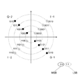
光変調の方法としては、様々な方法が考えられる。この数値例で示した1シンボル当り4ビットを割り当てる光多値変調の場合、例えば図3に示すような変調方法が考えられる。図3は、16APSK(APSK:Amplitude and Phase Shift Keying)の特殊な信号点配置を示している。振幅を4通り、位相をπ/2ずつ異なる4通りで分類する。マッピング方法としては、例えば、1シンボル当り4ビットのうち、MSB側の2ビットを複素平面の象限の分類(I−1、I−2、Q−1、Q−2)、LSB側の2ビットを各象限内でのビット分類にそれぞれ割り当てる方法が考えられる。なお、この例以外の方法も考えられる。 Various methods can be considered as a method of light modulation. In the case of optical multilevel modulation in which 4 bits are assigned per symbol shown in this numerical example, for example, a modulation method as shown in FIG. 3 can be considered. FIG. 3 shows a special signal point arrangement of 16APSK (APSK: Amplitude and Phase Shift Keying). The amplitude is classified into four types and the phase is classified into four types that are different by π / 2. As a mapping method, for example, out of 4 bits per symbol, 2 bits on the MSB side are classified into quadrants in the complex plane (I-1, I-2, Q-1, Q-2), and 2 bits on the LSB side. Can be assigned to each bit classification in each quadrant. A method other than this example is also conceivable.
また、1シンボル当り3ビットを割り当てる光多値変調の別の例としては、例えば図2に示すような変調方法が考えられる。図2は、8APSKの特殊な信号点配置を示している。振幅を2通り、位相をπ/2ずつ異なる4通りで分類する。マッピング方法としては、例えば、1シンボル当り4ビットのうち、MSB側の2ビットを複素平面の象限の分類、LSB側の1ビットを各象限内でのビット分類にそれぞれ割り当てる方法が考えられる。なお、この例以外の方法も考えられる。 Further, as another example of optical multilevel modulation in which 3 bits are assigned per symbol, a modulation method as shown in FIG. 2 can be considered, for example. FIG. 2 shows a special signal point arrangement of 8APSK. The amplitude is classified into two types and the phase is classified into four types that are different by π / 2. As a mapping method, for example, among 4 bits per symbol, 2 bits on the MSB side are assigned to the quadrant classification in the complex plane, and 1 bit on the LSB side is assigned to the bit classification in each quadrant. A method other than this example is also conceivable.
なお、図2や図3のような特殊な信号点配置にしているのは、現状の光デバイス技術では遅延検波による復調しか技術的に確立しておらず、そのため位相の区切りをπ/2とすることが限界であることが理由である。今後、光デバイス技術の進歩により同期検波が可能となれば、位相の区切りをより細かくするような信号点配置を導入することを視野に入れることができる。 Note that the special signal point arrangement as shown in FIG. 2 or FIG. 3 is that the current optical device technology has only technically established demodulation by delay detection, and therefore the phase separation is π / 2. The reason is to do so. In the future, if synchronous detection becomes possible due to advances in optical device technology, it is possible to consider introducing signal point arrangements that make phase separation finer.
つづいて、図1の下段に示す受信装置において、ライン側より受信した30Gs/sの受信信号(受信信号系列)を、受光回路21で受け取り、光信号を電気信号(アナログ形式)へ変換する。
Next, in the receiving apparatus shown in the lower part of FIG. 1, a received signal (received signal series) of 30 Gs / s received from the line side is received by the
次に、AD変換器22及び多重分離回路23では、アナログ形式の電気信号を量子化してディジタル形式に変換し、さらにあらかじめ定められている並列数に多重分離する。
Next, the
以上の処理の流れを図4で詳しく記す。図4は、1シンボルあたり4ビットを割り当てる光多値変調の例を示す。変調方式が異なれば、この構成は変わってくるが、多値変調であればここに記載する原理を導入することは可能である。 The above processing flow will be described in detail with reference to FIG. FIG. 4 shows an example of optical multilevel modulation in which 4 bits are assigned per symbol. If the modulation method is different, this configuration will change, but if it is multilevel modulation, the principle described here can be introduced.
図4において、ライン側より受信した光信号を受光回路21の分波器211で分ける。これにより、I軸側とQ軸側とでそれぞれ別個の識別を実施する。遅延検波器(1−bit delay)212と、O/E変換器213と、増幅器214とにより、光信号を電気信号(アナログ形式)へ変換する。
In FIG. 4, the optical signal received from the line side is divided by the
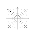
受光回路21の増幅器214より出力されたアナログ形式の電気信号に対し、ADC22により量子化を実施する。この例では、I軸側、Q軸側それぞれに対し、複数のADC22を並列に並べて、軸内のどの点に落ちたかを識別する。例えば、図5に示すような信号点配置の場合、I軸側では、I−1象限を識別するADC22と、I−2象限を識別するADC22とを利用して、受信信号がどの領域に落ちたかを識別する。また、Q軸側では、Q−1象限を識別するADC22と、Q−2象限を識別するADC22とを利用して、受信信号がどの領域に落ちたかを識別する。個々のADC22は、3つもしくは4つの閾値を区別できるものとする。図中の二重線で示したものが閾値である。
The
また、図6に示すような信号点配置の場合も同様に、I軸側では、I−1象限を識別するADC22と、I−2象限を識別するADC22とを利用して、受信信号がどの領域に落ちたかを識別する。また、Q軸側では、Q−1象限を識別するADC22と、Q−2象限を識別するADC22とを利用して、受信信号がどの領域に落ちたかを識別する。個々のADC22は、3つの閾値を区別できるものとする。
Similarly, in the case of the signal point arrangement as shown in FIG. 6, on the I-axis side, the received signal is determined by using the
ここで、ADC22の具体的な動作について、図7を参照しながら説明する。個々のADC22は、入力されたアナログ電気信号が、自らが設定した複数本の閾値のどの間に落ちるか(もしくはその外側か)を判定する。図7の例では、ADC22は2ビットの判定のみができるもので、閾値を3本設定できる。よって、判定としては4通りある。判定領域として、各象限において、I軸を45度時計周り、またはQ軸を45度反時計周りさせた状態で、垂直の方向になった3本の閾値(二重線)で区切られた、左から数えて1本目の閾値の左側の領域である「左端」と、1本目の閾値と2本目の閾値の間の領域である「中央左側」と、2本目の閾値と3本目の閾値の間の領域である「中央右側」と、3本目の閾値の右側の領域である「右端」との4つの領域となる。
Here, a specific operation of the
例えば、図7の×印に示す受信信号を受信した場合を考える。I−1象限のADC22では、受信信号は閾値I−B(1本目の閾値)と閾値I−A(2本目の閾値)の間(「中央左側」)に落ちたと判定する。I−2象限のADC22では、受信信号は左から数えて3本目の閾値の右側の領域である「右端」に落ちたと判定する。同様に、Q−2象限のADC22では、受信信号は閾値Q−C(2本目の閾値)と閾値Q−D(3本目の閾値)の間(「中央右側」)に落ちたと判定する。Q−1象限のADC22では、受信信号は1本目の閾値の左側の領域である「左端」に落ちたと判定する。このようにして、4個のADC22により、受信信号が領域Eに落ちたものとして判定する。
For example, consider a case where a reception signal indicated by a cross in FIG. 7 is received. The
光伝送システムにおいて、1個のADCでは、光信号の1シンボル当り高々数ビット程度の量子化受信系列への変換だけしか行うことができないという問題がある。この実施の形態1では、ADCを複数個並列に並べることにより、光多値変調に対する復調の精度を高くすることができる。図7の例では、図中の点線で示した領域分割(7×7)が可能となる。なお、図7の例では、位相を識別する軸をI軸とQ軸との2軸として、それぞれの軸にADCを2個ずつ配置しているが、ADCを3個以上で並列に配置することも可能であるし、位相を識別する軸を3軸以上することも可能である。 In an optical transmission system, there is a problem that a single ADC can only perform conversion into a quantized reception sequence of about several bits at most per symbol of an optical signal. In the first embodiment, the accuracy of demodulation for optical multilevel modulation can be increased by arranging a plurality of ADCs in parallel. In the example of FIG. 7, the area division (7 × 7) indicated by the dotted line in the figure is possible. In the example of FIG. 7, the axis for identifying the phase is two axes of the I axis and the Q axis, and two ADCs are arranged on each axis, but three or more ADCs are arranged in parallel. It is also possible to have three or more axes for identifying the phase.
複数個のADC22により量子化された受信信号系列を、多重分離回路23によりあらかじめ定められた並列数に並列化する。一例としては、32並列に多重分離する。並列化された量子化受信信号系列を、デマッパ24へ出力する。
The received signal sequence quantized by the plurality of
デマッパ24では、量子化受信信号系列を、量子化受信ビット系列へ変換する。それを誤り訂正符号の復号器25へ出力する。
The
デマッパ24での変換方法は、信号点配置と誤り訂正符号の方式などにより、様々な方式が考えられる。例えば、図7のような信号点配置と、LDPC符号を利用した場合、デマッパの形式として、以下のような方式が考えられる。I軸側、Q軸側それぞれの落ちた領域を示す量子化受信信号系列を、例えばI軸側を行、Q軸側を列とする2次元の表形式のどの「ます」に落ちたかを示すものとみなす。図7の例では、その「ます」を点線で示す。デマッパ24の出力値を、LDPC符号の符号語のそれぞれのビットに対応する対数尤度比(LLR:Log−Likelihood Ratio)とする。このとき、各ますには、1シンボル当り3ビット分のLLRの出力値をあらかじめ割り当てておき、それをメモリに保存しておく。デマッパ24の動作としては、デマッパ24に入力される量子化受信信号系列より、どのますに落ちたかを判断し、そのますに割り当てられたLLRを出力する、というものにする。なお、図5に記載の信号点配置でも、上記の変換方法を実施することができる。
Various conversion methods by the
デマッパ24より出力された、あらかじめ定められた並列数の数値(例えば、32×4並列のLLRの系列)より、復号器25では、誤り訂正符号の復号を実施する。例えば、LDPC符号により符号化された系列に対する復号であれば、sum−product復号、min−sum復号、およびそれらを改良した各種の軟判定繰り返し復号により、復号処理を実施する。なお、符号化器13で複数の符号化処理を並列に実施している場合、復号処理においても、それに応じて複数の処理を並列で実施することが好ましい。例えば、一例としてあげた矢印一本当り並列数32を、復号器25の並列数として、復号器32並列実装というものを採用しても良い。このとき、符号化率3/4の誤り訂正符号を用い、一つの復号器25に受信系列を4並列で入力し、復号の結果として算出される推定符号語系列(=推定情報系列+推定パリティ系列)を4並列で出力する。このとき、符号長nは、入力クロック数×4となる。
Based on a predetermined number of parallel numbers (for example, 32 × 4 parallel LLR sequences) output from the
復号器25で復号処理され、得られた120Gb/sの出力系列(推定符号語系列)を、デフレーマ26でデフレーム処理を実施し、90Gb/sの推定情報系列を出力する。
The output sequence (estimated codeword sequence) of 120 Gb / s obtained by decoding processing by the
デフレーマ26から出力された90Gb/sの推定情報系列を、受信側ターミナル/モニタ回路27が受け取り、誤り状態モニタリングなどを実施後、最終的に処理完了した系列をクライアント側へ90Gb/s速度で受け渡す。
The 90 Gb / s estimated information sequence output from the
ここで、信号点マッピングについて説明する。多値変調では、1シンボルあたり複数ビットを割り当てるが、この割り当てられたビットの種類によって、復調後のビット誤り率が異なるという性質がある。つまり、個々の送信信号点に割り当てる複数の送信ビットには、ビット誤り率の不均一性があるといえる。例えば、図2または図3に示した信号点配置では、MSBとLSBとでビット誤り率が異なる。それぞれのビット誤り率の性質やそれら差異は、信号対雑音比や通信路の雑音モデルなどによって異なる。 Here, the signal point mapping will be described. In multi-level modulation, a plurality of bits are assigned per symbol, and the bit error rate after demodulation differs depending on the type of assigned bits. That is, it can be said that a plurality of transmission bits allocated to individual transmission signal points have non-uniform bit error rates. For example, in the signal point arrangement shown in FIG. 2 or FIG. 3, the bit error rate is different between the MSB and the LSB. The nature of each bit error rate and the difference between them vary depending on the signal-to-noise ratio, the noise model of the communication channel, and the like.
光通信の例では、光信号の強度が強い場合(信号点の原点からの距離が遠い場合)が、それが弱い場合に比べて雑音分散値が大きくなる、という性質がある。また、位相方向の雑音の傾向も通信路状況や検波回路構成によって変動する。以下では説明のため、復調後のMSBのビット誤り率PMが、復調後のLSBのビット誤り率PLに比べて小さい(PM<PL)ものとする。 In the example of optical communication, when the intensity of the optical signal is strong (when the distance from the origin of the signal point is far), there is a property that the noise variance value becomes larger than when it is weak. In addition, the tendency of noise in the phase direction also varies depending on the channel condition and the detection circuit configuration. In the following, for the sake of explanation, it is assumed that the bit error rate P M of the MSB after demodulation is smaller than the bit error rate P L of the LSB after demodulation (P M <P L ).
一方で、誤り訂正符号においても、例えばパリティ検査行列の列重み(列ベクトルの要素で1となる要素数)を不均一にした非正則(irregular)LDPC符号の場合、符号語の各ビットは、それに対応する列重みに応じて、復号後のビット誤り率が異なってくることが知られている。図8左側に記す、符号長nビットの非正則LDPC符号の符号語が、ラベル(説明のための記号)ck1で示す列重みが大きい情報系列(系列長k1)と、ラベルck2で示す列重みが小さい情報系列(系列長k2)と、ラベルcrで示すパリティ系列(系列長r、列重みが情報系列より小さいものとする)とに分類できるとする。このとき、ck1、ck2、cr、それぞれのビット誤り確率pk1、pk2、pr、を比較すると、pk1<pk2<prという関係が成り立つ。 On the other hand, even in the error correction code, for example, in the case of an irregular LDPC code in which the column weight of the parity check matrix (the number of elements that are 1 in the column vector) is nonuniform, each bit of the codeword is: It is known that the bit error rate after decoding varies depending on the corresponding column weight. The code word of the non-regular LDPC code having a code length of n bits shown on the left side of FIG. 8 is indicated by an information sequence (sequence length k1) having a large column weight indicated by a label (description symbol) c k1 and a label c k2 the column weight is small information sequence (sequence length k2), and can be classified into the parity sequence indicated by the label c r (sequence length r, assumed column weight is less than information sequence). In this case, c k1, c k2, c r, each bit error probability p k1, p k2, p r , a comparison of the relationship that p k1 <p k2 <p r holds.
よって、以上のような多値変調における送信ビットの送信ビット誤り率不均一性と、誤り訂正符号の復号後ビット誤り率不均一性とを好適に組み合わせることを、この実施の形態1で実施する。 Therefore, the first embodiment implements a suitable combination of the transmission bit error rate non-uniformity of the transmission bits in the multi-level modulation as described above and the post-decoding bit error rate non-uniformity of the error correction code. .
前述のビット誤り率不均一性を考慮した信号点マッピング方法については、様々な方法が考えられる。一例を図8(最下段から2段目)に記載する。割り付け方法Aとして、一重楕円で示す復号後ビット誤り率の低いビット(ck1およびck2の一部)に復調後ビット誤り率の高いもの(SL)を、二重楕円で示す復号後ビット誤り率の高いビット(ck2の一部およびcr)に復調後ビット誤り率の低いもの(SM)を、というように割り付ける方法である。この方法は、送信ビット誤り率と復号後ビット誤り率とを平均化すること、信号平面における符号化信号点系列間の最小ユークリッド距離の最大化を図るという意図がある。 Various methods can be considered for the signal point mapping method considering the bit error rate non-uniformity described above. An example is shown in FIG. 8 (second row from the bottom). As allocation method A, a bit having a low post-decoding bit error rate (a part of c k1 and c k2 ) indicated by a single ellipse and a bit having a high post-demodulation bit error rate (S L ) are indicated by a double ellipse. In this method, bits having a high error rate (part of c k2 and c r ) are assigned with a low demodulated bit error rate (S M ). This method has the intention of averaging the transmission bit error rate and the decoded bit error rate and maximizing the minimum Euclidean distance between encoded signal point sequences in the signal plane.
また、別の一例を図8(最下段)に記載する。割り付け方法Bとして、二重楕円で示す復号後ビット誤り率の低いビット(ck1およびck2の一部)に復調後ビット誤り率の低いもの(SM)を、一重楕円で示す復号後ビット誤り率の高いビット(ck2の一部およびcr)に復調後ビット誤り率の高いもの(SL)を、というように割り付ける方法である。この方法は、LDPC符号における繰り返し復号において、まずビット誤り率の低いものから訂正し、その結果を繰り返し利用することでビット誤り率の高いものも復号することを図るという意図がある。 Another example is shown in FIG. 8 (bottom row). As the allocation method B, a bit with a low post-decoding bit error rate (a part of c k1 and c k2 ) indicated by a double ellipse (S M ) with a low bit error rate after demodulation is represented by a single oval. This is a method of allocating bits (S L ) having a high bit error rate after demodulation to bits having a high error rate (part of c k2 and c r ). This method has an intention to first correct from a low bit error rate in LDPC code, and to decode a result having a high bit error rate by repeatedly using the result.
上記の例のほかにも、ビット誤り率不均一性を考慮した信号点マッピング方法は、様々な方法が考えられる。それらのうちの最適な方法を決定する方法としては、例えば計算機シミュレーションを実施して、その結果、最も特性の良い組み合わせを選択する、という方法が考えられる。 In addition to the above example, there are various signal point mapping methods that take into account the bit error rate non-uniformity. As a method for determining an optimum method among them, for example, a computer simulation is performed, and as a result, a combination having the best characteristics is selected.
また、別の信号点マッピング方法およびその評価方法として、例えばLDPC符号を用いる場合、LDPC符号の解析方法として知られる密度発展法を用いる方法が考えられる。この密度発展法は、符号長が漸近的に無限大に近づく場合の繰り返し復号の確率密度関数を解析することで、復号誤り率特性を評価する方法である。変調方式(信号点配置)、通信路特性(ビット誤り率不均一性)を特定した条件で、列重みの組み合わせ、ビット割り当て(マッピング)の組み合わせを変動させ、密度発展法により解析し、その組み合わせのうちで最適なものを採用する、という方法も利用できる。 As another signal point mapping method and its evaluation method, for example, when an LDPC code is used, a method using a density evolution method known as an LDPC code analysis method is conceivable. This density evolution method is a method for evaluating the decoding error rate characteristic by analyzing a probability density function of iterative decoding when the code length asymptotically approaches infinity. Under conditions that specify modulation method (signal point arrangement) and channel characteristics (bit error rate non-uniformity), combinations of column weights and bit allocations (mappings) are varied, analyzed by the density evolution method, and the combinations The method of adopting the most suitable among them can also be used.
信号点マッピングの実装(装置化)方法としては、様々な構成を適用することができる。符号化器13とマッパ14との間で伝達されるデータ(誤り訂正符号の符号語の系列)を受け渡す方法としては、各回路間を接続するパスを経由するパイプライン方式で受け渡されるように構成しても良いし、各回路間に前後の回路から参照可能な作業用記憶領域を設ける構成にしてもよい。以上のような構成で系列のビット並び替えを実施した後、あらかじめ定められた信号点配置に基づいて信号点を特定してその結果を出力する。その結果出力の機能は、信号点を特定させるためのビットを同期させて出力させられるようになっていればよく、その実装方法、回路構成は様々な方法を採用することができる。
Various configurations can be applied as a signal point mapping implementation (equipmentization) method. As a method of transferring data (sequence of error correction code codewords) transmitted between the
なお、この実施の形態1は、上記の具体例に記載したパラメータに制約されるものではなく、誤り訂正符号化の方法、フレームフォーマットの長さ、多値変調の多値数、伝送速度など、うまく当てはめられる組み合わせであれば、別の具体例として実現されるものである。 The first embodiment is not limited to the parameters described in the above specific example, and includes an error correction coding method, a frame format length, a multi-level number of multi-level modulation, a transmission rate, etc. A combination that can be applied well is realized as another specific example.
また、この実施の形態1は、光伝送システムに限定されて適用されるものではなく、加入者系有線通信、モバイル無線通信、衛星通信など、様々な種類の伝送システムへ適用ができるものである。 The first embodiment is not limited to the optical transmission system and can be applied to various types of transmission systems such as subscriber wired communication, mobile wireless communication, and satellite communication. .
この実施の形態1では、以上のように、送信ビット誤り不均一性を考慮して、また復号後ビット誤り率不均一性を考慮して、信号点マッピングを選択、利用することができるので、効率の良い、かつビット誤り率特性の良い符号化変調を実行することができる。 In the first embodiment, as described above, signal point mapping can be selected and used in consideration of transmission bit error non-uniformity and post-decoding bit error rate non-uniformity. It is possible to execute coding modulation with high efficiency and good bit error rate characteristics.
また、この実施の形態1では、以上のように、非常に高速なシンボルレートの光伝送システムにおいて、複数のADCを並列に配置して、複数のADCで識別範囲を割り当てることができるので、1シンボル当りの量子化ビット数を増やすことができ、光多値変調と誤り訂正を組み合わせた符号化変調を実行することができる。 In the first embodiment, as described above, in an optical transmission system with a very high symbol rate, a plurality of ADCs can be arranged in parallel and an identification range can be assigned by a plurality of ADCs. The number of quantization bits per symbol can be increased, and coded modulation combining optical multilevel modulation and error correction can be executed.
実施の形態2.
この発明の実施の形態2に係る光伝送システムについて図9及び図10を参照しながら説明する。図9は、この発明の実施の形態2に係る光伝送システムの構成を示す図である。
An optical transmission system according to
図9において、この実施の形態2に係る光伝送システムは、上段に示す送信装置と、下段に示す受信装置とが設けられている。 In FIG. 9, the optical transmission system according to the second embodiment is provided with a transmitting apparatus shown in the upper stage and a receiving apparatus shown in the lower stage.
送信装置は、送信側ターミナル/モニタ回路(Term/Mon)11と、フレーマ(Framer)12と、符号化器(Encoder−1)13A、符号化器(Encoder−2)13B、符号化器(Encoder−3)13Cと、マッパ(Mapper)14と、多重化器(MUX:Multiplexer)15と、光変調器(m−bit Optical Modulator)16とが設けられている。
The transmitting apparatus includes a transmitting terminal / monitor circuit (Term / Mon) 11, a
また、受信装置は、受光回路(m−bit Optical Receiver:analogue out)21と、AD変換器(n−bit ADC:Analog Digital Converter)22と、多重分離回路(DEMUX:De−Multiplexer)23と、デマッパ(De−mapper)24と、復号器(Decoder−1)25A、復号器(Decoder−2)25B、復号器(Decoder−3)25Cと、デフレーマ(De−framer)26と、受信側ターミナル/モニタ回路(Term/Mon)27とが設けられている。 The receiving apparatus includes a light receiving circuit (m-bit Optical Receiver: analog out) 21, an AD converter (n-bit ADC: Analog Digital Converter) 22, a demultiplexing circuit (DEMUX: De-Multiplexer) 23, Demapper (De-mapper) 24, Decoder (Decoder-1) 25A, Decoder (Decoder-2) 25B, Decoder (Decoder-3) 25C, Deframer (De-framer) 26, and receiving terminal / A monitor circuit (Term / Mon) 27 is provided.
つぎに、この実施の形態2に係る光伝送システムの動作について図面を参照しながら説明する。図10は、この発明の実施の形態2で実施するマッピング方法の一例を詳細に示す図である。 Next, the operation of the optical transmission system according to the second embodiment will be described with reference to the drawings. FIG. 10 is a diagram showing in detail an example of the mapping method implemented in the second embodiment of the present invention.
この実施の形態2では、上記の実施の形態1による通信路のシンボルレートを抑える手段において、光多値変調を実施するが、光多値変調における1送信シンボル当りのビット数を拡大する代わりに、各ビットのレートをFECパリティ分だけ上昇させる方法を採用するものである。 In this second embodiment, optical multilevel modulation is performed in the means for suppressing the symbol rate of the communication channel according to the first embodiment, but instead of increasing the number of bits per transmission symbol in optical multilevel modulation. In this method, the rate of each bit is increased by the FEC parity.
図9は、上記の実施の形態1の条件に基づいて記載したものであるが、一部異なる部分がある。情報伝送レートを上記の実施の形態1と同様に例えば90Gb/sとして、情報系列を冗長度平均1/3(約33%)の誤り訂正符号により符号化をしてFECパリティを付加する。符号語系列のトータルのビットレートが120Gb/sになるが、変調後のシンボルレートを40Gs/sとする。つまり、送信符号語のビットレートおよび送信シンボルレートを上昇させることが、上記の実施の形態1とは異なる。 FIG. 9 is described based on the conditions of the first embodiment, but there are some differences. As in the first embodiment, the information transmission rate is set to 90 Gb / s, for example, and the information sequence is encoded with an error correction code having an average redundancy of 1/3 (about 33%) and an FEC parity is added. The total bit rate of the codeword sequence is 120 Gb / s, but the symbol rate after modulation is 40 Gs / s. That is, the bit rate and the transmission symbol rate of the transmission codeword are increased from the first embodiment.
また、この実施の形態2では、誤り訂正符号として複数種類の符号を並列に処理する、マルチレベル符号化の形式を採用する。図9に示す符号化器13A、13B、13Cは、異なる符号で符号化処理することを表している。採用する符号の符号長、符号化率などは、この光伝送システムの条件に合致するものであれば、様々なものを採用することができる。また、FECフレームサイズ自体が例えば10000ビット以上というような非常に長い条件では、複数の符号化処理を並列に実行することも可能である。例えば、一例としてあげた矢印一本当り並列数32を、符号化器13A、13B、13Cの並列数として、符号化器32並列実装というものを採用しても良い。
In the second embodiment, a multilevel encoding format is used in which a plurality of types of codes are processed in parallel as error correction codes.
また、それぞれの符号の誤り訂正能力を不均一にすることも可能である。そのような方法を採用する場合、上記の実施の形態1と同様に、送信ビット誤り率不均一性と、複数種類の誤り訂正符号の訂正能力不均一性を考慮して、信号点マッピングを好適に選択することを実施することが可能となる。 It is also possible to make the error correction capability of each code non-uniform. When such a method is adopted, signal point mapping is suitable in consideration of transmission bit error rate non-uniformity and non-uniformity of correction ability of a plurality of types of error correction codes, as in the first embodiment. It is possible to implement the selection.
マルチレベル符号化、およびそれぞれの符号の誤り訂正能力を不均一にする方法を採用する場合の、信号点マッピングの方法の一例を以下で説明する。 An example of a signal point mapping method in the case of employing multilevel coding and a method of making error correction capability of each code non-uniform will be described below.
図10に基づく多値変調を実施した場合、上記の実施の形態1で説明したとおり、個々の送信信号点に割り当てる複数の送信ビットには、復調後のビット誤り率の不均一性がある。以下では説明のため、復調後のMSBのビット誤り率PMが、復調後のLSBのビット誤り率PLに比べて小さい(PM<PL)ものとする。 When multilevel modulation based on FIG. 10 is performed, as described in the first embodiment, a plurality of transmission bits allocated to individual transmission signal points have non-demodulated bit error rates. In the following, for the sake of explanation, it is assumed that the bit error rate P M of the MSB after demodulation is smaller than the bit error rate P L of the LSB after demodulation (P M <P L ).
一方で、誤り訂正符号においても、マルチレベル符号化およびそれぞれの符号の誤り訂正能力を不均一にする方法の採用により、復号後のビット誤り率が異なる。図10の左側に記載する、符号長nビットの符号化器(Encoder−1)13Aにより符号化された符号語が、ラベルck1で示す情報系列(系列長k1)と、ラベルcr1で示すパリティ系列(系列長r1)とに分類できるとする。同様に、符号長nビットの符号化器(Encoder−2)13Bにより符号化された符号語が、ラベルck2で示す情報系列(系列長k2)と、ラベルcr2で示すパリティ系列(系列長r2、r1>r2)とに分類でき、符号長nビットの符号化器(Encoder−3)13Cにより符号化された符号語が、ラベルck3で示す情報系列(系列長k3)と、ラベルcr3で示すパリティ系列(系列長r3、r2>r3)とに分類できるとする。このとき、ck1、ck2、ck3、cr1、cr2、cr3、それぞれのビット誤り確率pk1、pk2、pk3、pr1、pr2、pr3、を比較すると、pk1<pr1<pk2<pr2<pk3<pr3という関係が成り立つものとする。 On the other hand, error correction codes also have different bit error rates after decoding due to the use of multilevel coding and a method for making the error correction capability of each code non-uniform. Described on the left side of FIG. 10, the code length n bits of an encoder (Encoder-1) code word encoded by 13A is a information sequence indicated by the label c k1 (sequence length k1), indicated by the label c r1 It can be classified into a parity sequence (sequence length r1). Similarly, code length n bits of encoder code words encoded by (Encoder-2) 13B is an information sequence indicated by the label c k2 (sequence length k2), parity sequence (the sequence length indicated by the label c r2 r2, r1> r2), and a code word encoded by an encoder (Encoder-3) 13C having a code length of n bits is an information sequence (sequence length k3) indicated by a label c k3 and a label c It can be classified into the parity sequence indicated by r3 (sequence length r3, r2> r3). At this time, when c k1 , c k2 , c k3 , c r1 , c r2 , c r3 are compared with their respective bit error probabilities p k1 , p k2 , p k3 , p r1 , p r2 , p r3 , p k1 <P r1 <p k2 <p r2 <p k3 <p r3 is assumed to be satisfied.
以上のような多値変調における送信ビットの送信ビット誤り率不均一性と、誤り訂正符号の復号後ビット誤り率不均一性とを好適に組み合わせることを、この実施の形態2では実施する。 In the second embodiment, the transmission bit error rate non-uniformity of the transmission bits in the multi-level modulation as described above and the post-decoding bit error rate non-uniformity of the error correction code are suitably combined.
符号化器13A、13B、13Cにより符号化された、3種類の符号語のビット系列を、復号後ビット誤り率の低いものから順番に並び替える。その並び替えた後のビット系列を用いて、マッパ14により信号点マッピングを実施する。
The bit sequences of the three types of codewords encoded by the
前述のビット誤り率不均一性を考慮した信号点マッピング方法については、上記の実施の形態1と同様に、様々な方法が考えられる。一例を図10に記載する。割り付け方法Aとして、一重楕円で示す復号後ビット誤り率の低いビット(ラベルck1,cr1の辺り)に復調後ビット誤り率の高いもの(SL)を、二重楕円で示す復号後ビット誤り率の高いビット(ラベルck2,cr2,ck3,cr3の辺り)に復調後ビット誤り率の低いもの(SM)を、というような割り付ける方法である。この方法の意図は、上記の実施の形態1と同様である。 As the signal point mapping method considering the bit error rate non-uniformity described above, various methods are conceivable as in the first embodiment. An example is described in FIG. As allocation method A, a bit with a low post-decoding bit error rate (around labels c k1 and c r1 ) indicated by a single ellipse (S L ) with a high post-demodulation bit error rate is represented by a double ellipse. the high error rate bit (labeled c k2, c r2, c k3 , around c r3) to having a low post-demodulation bit error rate (S M), a method for allocating such that. The intention of this method is the same as that of the first embodiment.
また、別の一例として、割り付け方法Bは、割り付け方法Aと逆の順序で、二重楕円で示す復号後ビット誤り率の低いビットに復調後ビット誤り率の低いもの(SM)を、一重楕円で示す復号後ビット誤り率の高いビットに復調後ビット誤り率の高いもの(SL)を、というように割り付ける方法である。この方法の意図は、上記の実施の形態1と同様である。上記の例のほかにも、ビット誤り率不均一性を考慮した信号点マッピング方法は、上記の実施の形態1と同様に様々な方法が考えられる。 As another example, in allocation method B, a bit with a low post-decoding bit error rate (S M ) is assigned to a bit with a low post-decoding bit error rate indicated by a double ellipse in reverse order to allocation method A. In this method, a bit having a high bit error rate after decoding (S L ) is assigned to a bit having a high bit error rate after decoding indicated by an ellipse. The intention of this method is the same as that of the first embodiment. In addition to the above example, various signal point mapping methods considering bit error rate non-uniformity can be considered as in the first embodiment.
この実施の形態2では、以上のように、送信ビット誤り不均一性を考慮して、また複数種類の誤り訂正符号の訂正能力不均一性を考慮して、信号点マッピングを選択、利用することができるので、効率の良い、かつビット誤り率特性の良い符号化変調を実行することができる。また、この実施の形態2の説明では、送信信号に割り当てる複数ビットの各ビットのビット誤り率が不均一であることと、誤り訂正符号の各ビットに復号後のビット誤り率が不均一であることと、誤り訂正符号の種類の違いによって誤り訂正能力が不均一であることという3条件を考慮して、信号点マッピングを選択する方法を説明したが、別の構成として、送信信号に割り当てる複数ビットの各ビットのビット誤り率が不均一であることと、誤り訂正符号の種類の違いによって誤り訂正能力が不均一であることという2条件を考慮して、信号点マッピングを選択、利用することができるので、効率の良い、かつビット誤り率特性の良い符号化変調を実行することができる。 In the second embodiment, as described above, signal point mapping is selected and used in consideration of transmission bit error non-uniformity and in consideration of correction capability non-uniformity of plural types of error correction codes. Therefore, it is possible to execute code modulation with high efficiency and good bit error rate characteristics. In the description of the second embodiment, the bit error rate of each bit of the plurality of bits allocated to the transmission signal is non-uniform and the bit error rate after decoding is non-uniform for each bit of the error correction code. In addition, the method of selecting the signal point mapping has been described in consideration of the three conditions that the error correction capability is nonuniform due to the difference in the type of error correction code. Select and use signal point mapping in consideration of the two conditions that the bit error rate of each bit is non-uniform and the error correction capability is non-uniform due to the difference in the type of error correction code. Therefore, it is possible to execute code modulation with high efficiency and good bit error rate characteristics.
実施の形態3.
この発明の実施の形態3に係る光伝送システムについて図11及び図12を参照しながら説明する。図11は、この発明の実施の形態3に係る光伝送システムの構成を示す図である。
An optical transmission system according to
図11において、この実施の形態3に係る光伝送システムは、上段に示す送信装置と、下段に示す受信装置とが設けられている。 In FIG. 11, the optical transmission system according to the third embodiment is provided with a transmitting apparatus shown in the upper stage and a receiving apparatus shown in the lower stage.
送信装置は、送信側ターミナル/モニタ回路(Term/Mon)11と、フレーマ(Framer)12と、外符号化器(Outer−Encoder)17と、内符号化器(Inner−Encoder)18と、マッパ(Mapper)14と、多重化器(MUX:Multiplexer)15と、光変調器(m−bit Optical Modulator)16とが設けられている。
The transmission apparatus includes a transmission side terminal / monitor circuit (Term / Mon) 11, a
また、受信装置は、受光回路(m−bit Optical Receiver:analogue out)21と、AD変換器(n−bit ADC:Analog Digital Converter)22と、多重分離回路(DEMUX:De−Multiplexer)23と、デマッパ(De−mapper)24と、内復号器(Inner−Decoder)28と、外復号器(Outer−Decoder)29と、デフレーマ(De−framer)26と、受信側ターミナル/モニタ回路(Term/Mon)27とが設けられている。
The receiving apparatus includes a light receiving circuit (m-bit Optical Receiver: analog out) 21, an AD converter (n-bit ADC: Analog Digital Converter) 22, a demultiplexing circuit (DEMUX: De-Multiplexer) 23,
つぎに、この実施の形態3に係る光伝送システムの動作について図面を参照しながら説明する。図12は、この発明の実施の形態1〜3のフレームフォーマットを示す図である。 Next, the operation of the optical transmission system according to the third embodiment will be described with reference to the drawings. FIG. 12 shows a frame format according to the first to third embodiments of the present invention.
上記の実施の形態1又は実施の形態2では、符号化変調もしくはマルチレベル符号化を実施するが、この実施の形態3では、符号化変調もしくはマルチレベル符号化による誤り保護に加えて、その外側から別の誤り訂正符号による誤り保護を実施するものである。 In the first embodiment or the second embodiment, coding modulation or multilevel coding is performed. In the third embodiment, in addition to error protection by coding modulation or multilevel coding, the outside of the coding modulation or multilevel coding is performed. Thus, error protection by another error correction code is performed.
図11は、上記の実施の形態1の条件に基づいて記載したものであるが、一部異なる部分がある。上記の実施の形態1における符号化変復調部分は、図11において、内符号化器18とマッパ14、デマッパ24と内復号器28の部分となる。この実施の形態3では、その外側から外符号化器17により別の符号化を実施する。この符号を外符号と呼ぶ。外符号としては、例えばReed−Solomon符号などのブロック符号を選択する。
FIG. 11 is described based on the conditions of the first embodiment described above, but there are some differences. In FIG. 11, the encoding / modulation part in the first embodiment is the part of the
符号化パラメータとしては、上記の実施の形態1又は実施の形態2と同様に、光伝送システムの送信データフレームフォーマットや光デバイスなどの条件に合致すれば、自由に選択できる。ただし、例えば情報系列のビットレートが90Gb/sとして、誤り訂正符号の冗長度1/3(約33%)という制約条件が課せられていた場合、この実施の形態3で利用する外符号のパリティ系列は、符号化変調で利用する誤り訂正符号(ここでは内符号と呼ぶ)と合わせて冗長度1/3とする必要があることとなる。つまり、上記の実施の形態1又は実施の形態2に比べて、内符号に利用できる冗長度が減ることとなる。そのことを図12に記載する。 As in the first embodiment or the second embodiment, the encoding parameter can be freely selected as long as it matches the conditions such as the transmission data frame format and the optical device of the optical transmission system. However, for example, when the bit rate of the information sequence is 90 Gb / s and the constraint condition that the error correction code redundancy is 1/3 (about 33%) is imposed, the parity of the outer code used in the third embodiment is used. The series needs to have a redundancy of 1/3 together with an error correction code (herein referred to as an inner code) used in coding modulation. That is, the redundancy that can be used for the inner code is reduced as compared with the first embodiment or the second embodiment. This is described in FIG.
図12(a)が上記の実施の形態1又は実施の形態2を、図12(b)がこの実施の形態3のフレームフォーマットを示す。図12(a)は、横方向に6個のLDPC符号により符号化したものとする。図12(b)は、斜め方向に複数個(図を見やすくするために一部を省略する)のRS符号により外符号化し、横方向に6個のLDPC符号により内符号化したものとする。冗長度の総計r/kは同一という条件としている。すると、内符号のLDPC符号の冗長度が、図12(a)に比べて図12(b)の方が少ないことが分かる。よって、内符号の訂正能力も実施の形態3では低下することがわかる。しかし、RS符号などのブロック符号により外側から保護ずることにより、バーストエラーに対する訂正能力を向上することができる。 FIG. 12A shows the frame format of the first embodiment or the second embodiment, and FIG. 12B shows the frame format of the third embodiment. In FIG. 12A, it is assumed that encoding is performed with six LDPC codes in the horizontal direction. In FIG. 12 (b), it is assumed that a plurality of RS codes are omitted in the diagonal direction (a part of which is omitted for the sake of clarity), and an inner code is encoded by six LDPC codes in the horizontal direction. The total redundancy r / k is assumed to be the same. Then, it can be seen that the redundancy of the LDPC code of the inner code is smaller in FIG. 12B than in FIG. Therefore, it can be seen that the correction capability of the inner code is also reduced in the third embodiment. However, the ability to correct burst errors can be improved by protecting from the outside with a block code such as an RS code.
図12(b)のフレームフォーマットを利用する場合、外符号化器17と内符号化器18の間に、図11には図示していないインタリーブ回路を必要とする。また、内復号器28と外復号器29の間に、図11には図示していないデインタリーブ回路を必要とする。インタリーブ回路の実装(装置化)方法としては、様々な構成を適用することができる。外符号化器17と内符号化器18との間で伝達されるデータ(誤り訂正符号の符号語の系列)を受け渡す方法としては、各回路間を接続するパスを経由するパイプライン方式で受け渡されるように構成しても良いし、各回路間に前後の回路から参照可能な作業用記憶領域を設ける構成にしてもよい。デインタリーブ回路の実装(装置化)方法としては、インタリーブ回路で順序変換された系列をもとの順序に並べなおす機能が実現されていれば、インタリーブ回路と同様に様々な構成を適用することができる。また、FECフレームサイズ自体が例えば10000ビット以上というような非常に長い条件では、複数の外符号化処理を並列に実行することも可能である。例えば、外符号化器17の並列数を16として、符号化器16並列実装というものを採用しても良い。
When the frame format of FIG. 12B is used, an interleave circuit (not shown in FIG. 11) is required between the
この実施の形態3では、以上のように、送信ビット誤り不均一性を考慮して、また複数種類の誤り訂正符号の訂正能力不均一性を考慮して、信号点マッピングを選択、利用することができ、かつ外符号により誤り保護を実施するので、効率の良い、かつビット誤り率特性の良い符号化変調を実行することができ、かつバーストエラーに対する訂正能力を向上することができる。また、送信ビット誤り不均一性を考慮して、また外符号の復号後のビット誤り率の不均一性を考慮して、信号点マッピングを選択、利用することができ、かつ外符号により誤り保護を実施するので、効率の良い、かつビット誤り率特性の良い符号化変調を実行することができ、かつバーストエラーに対する訂正能力を向上することができる。 In the third embodiment, as described above, signal point mapping is selected and used in consideration of transmission bit error non-uniformity and in consideration of non-uniformity of correction ability of plural types of error correction codes. In addition, since the error protection is performed by the outer code, it is possible to execute the code modulation with high efficiency and good bit error rate characteristics, and improve the correction capability for the burst error. Also, signal point mapping can be selected and used in consideration of transmission bit error non-uniformity and non-uniformity of bit error rate after decoding of outer code, and error protection by outer code Therefore, it is possible to execute coding modulation with high efficiency and good bit error rate characteristics, and to improve the correction capability for burst errors.
1 光通信路、11 送信側ターミナル/モニタ回路、12 フレーマ、13、13A、13B,13C 符号化器、14 マッパ、15 多重化器、16 光変調器、17 外符号化器、18 内符号化器、21 受光回路、22 AD変換器、23 多重分離回路、24 デマッパ、25、25A、25B、25C 復号器、26 デフレーマ、27 受信側ターミナル/モニタ回路、28 内復号器、29 外復号器、211 分波器、212 遅延検波器、213 O/E変換器、214 増幅器。
DESCRIPTION OF
Claims (2)
前記送信装置は、
入力された情報系列を情報系列+ダミー系列へ変換するフレーマと、
前記情報系列+ダミー系列うち、情報系列のみを利用して誤り訂正符号の符号化を実施し、符号化に伴い生成したパリティ系列を、ダミー系列の部分に割り当て、前記情報系列と合わせた系列を符号語系列として出力する符号化器と、
1シンボルの送信信号に割り当てる複数ビットの各ビットに応じてビット誤り率が不均一であることと、誤り訂正符号の符号語の各ビットに復号後のビット誤り率が不均一であることを条件として、送信信号の信号点と誤り訂正符号のビットとの組み合わせを選択したビット割り当てで、前記符号語系列を信号点系列へ変換するマッパと、
前記信号点系列に対して多重化処理を実施して、所定のシンボルレートの信号点系列へ変換する多重化器と
を備え、
前記受信装置は、
並列に接続され、各々が複数の閾値を有し、アナログ形式の受信信号を量子化して、受信信号が2次元の表形式のどのますに落ちたかを示す、ディジタル形式の量子化受信信号系列に変換する複数のAD変換器と、
前記量子化受信信号系列を、前記2次元の表形式の各ますに予め割り当てられている対数尤度比である量子化受信ビット系列へ変換するデマッパと、
前記量子化受信ビット系列の復号処理を実施して推定情報系列と推定パリティ系列とを合わせた系列を推定符号語系列として出力する復号器と、
前記推定符号語系列についてデフレーム処理を実施し、推定情報系列を出力するデフレーマと
を備え
前記符号化変調信号は、信号点と誤り訂正符号のビットとの組み合わせを選択したビット割り当てがなされていることを特徴とする送受信装置。 A transmission / reception device comprising a transmission device that performs coding modulation that combines multi-level modulation and an error correction code, and a reception device that receives a coded modulation signal that combines multi-level modulation and an error correction code ,
The transmitter is
A framer for converting the input information sequence into an information sequence + dummy sequence;
An error correction code is encoded using only the information sequence out of the information sequence + dummy sequence, a parity sequence generated along with the encoding is assigned to a dummy sequence portion, and a sequence combined with the information sequence is An encoder that outputs a codeword sequence;
The condition is that the bit error rate is non-uniform according to each bit of a plurality of bits assigned to the transmission signal of one symbol, and that the bit error rate after decoding is non-uniform for each bit of the code word of the error correction code As a mapper that converts the codeword sequence into a signal point sequence with bit allocation that selects a combination of a signal point of a transmission signal and a bit of an error correction code;
A multiplexer that performs a multiplexing process on the signal point sequence and converts the signal point sequence into a signal point sequence of a predetermined symbol rate ;
The receiving device is:
A digitally-quantized received signal sequence connected in parallel, each having a plurality of thresholds, quantizing the received signal in analog format and indicating to which of the two-dimensional tabular format the received signal fell A plurality of AD converters for conversion;
A demapper for converting the quantized received signal sequence into a quantized received bit sequence that is a log-likelihood ratio assigned in advance to each of the two-dimensional tabular formats;
A decoder that performs a decoding process on the quantized received bit sequence and outputs a sequence obtained by combining the estimated information sequence and the estimated parity sequence as an estimated codeword sequence;
A deframer that performs deframe processing on the estimated codeword sequence and outputs an estimated information sequence;
With
The transmission / reception apparatus according to claim 1, wherein the coded modulation signal is assigned a bit by selecting a combination of a signal point and a bit of an error correction code .
前記送信方法は、
フレーマによって、入力された情報系列を情報系列+ダミー系列へ変換するステップと、
符号化器によって、前記情報系列+ダミー系列うち、情報系列のみを利用して誤り訂正符号の符号化を実施し、符号化に伴い生成したパリティ系列を、ダミー系列の部分に割り当て、前記情報系列と合わせた系列を符号語系列として出力するステップと、
マッパによって、1シンボルの送信信号に割り当てる複数ビットの各ビットに応じてビット誤り率が不均一であることと、誤り訂正符号の符号語の各ビットに復号後のビット誤り率が不均一であることを条件として、送信信号の信号点と誤り訂正符号のビットとの組み合わせを選択したビット割り当てで、前記符号語系列を信号点系列へ変換するステップと、
多重化器によって、前記信号点系列に対して多重化処理を実施して、所定のシンボルレートの信号点系列へ変換するステップと
を含み、
前記受信方法は、
並列に接続された複数のAD変換器によって、各々が複数の閾値を有し、アナログ形式の受信信号を量子化して、受信信号が2次元の表形式のどのますに落ちたかを示す、ディジタル形式の量子化受信信号系列に変換するステップと、
デマッパによって、前記量子化受信信号系列を、前記2次元の表形式の各ますに予め割り当てられている対数尤度比である量子化受信ビット系列へ変換するステップと、
復号器によって、前記量子化受信ビット系列の復号処理を実施して推定情報系列と推定パリティ系列とを合わせた系列を推定符号語系列として出力するステップと、
デフレーマによって、前記推定符号語系列についてデフレーム処理を実施し、推定情報系列を出力するステップと
を含み、
前記符号化変調信号は、信号点と誤り訂正符号のビットとの組み合わせを選択したビット割り当てがなされていることを特徴とする送受信方法。 A transmission / reception method comprising: a transmission method for performing code modulation combining multilevel modulation and an error correction code; and a reception method for receiving an encoded modulation signal combining multilevel modulation and an error correction code ,
The transmission method is:
Converting an input information sequence into an information sequence + dummy sequence by a framer;
An encoder performs encoding of an error correction code using only the information sequence out of the information sequence + dummy sequence, assigns a parity sequence generated along with the encoding to a dummy sequence portion, and Outputting a sequence combined with a codeword sequence;
The bit error rate is uneven according to each bit of a plurality of bits assigned to the transmission signal of one symbol by the mapper, and the bit error rate after decoding is not uniform for each bit of the code word of the error correction code On the condition that the code word sequence is converted to a signal point sequence by bit allocation that selects a combination of a signal point of a transmission signal and a bit of an error correction code;
Performing a multiplexing process on the signal point sequence by a multiplexer and converting the signal point sequence to a signal point sequence of a predetermined symbol rate , and
The receiving method is:
Digital format with multiple AD converters connected in parallel, each having multiple thresholds, quantizing the received signal in analog format and indicating to which of the two-dimensional tabular format the received signal fell Converting to a quantized received signal sequence of
Transforming the quantized received signal sequence by a demapper into a quantized received bit sequence that is a log likelihood ratio pre-assigned to each of the two-dimensional tabular forms;
Performing a decoding process of the quantized received bit sequence by a decoder and outputting a sequence obtained by combining the estimated information sequence and the estimated parity sequence as an estimated codeword sequence;
Performing deframe processing on the estimated codeword sequence by a deframer and outputting an estimated information sequence;
Including
A transmission / reception method characterized in that the coded modulation signal is assigned a bit by selecting a combination of a signal point and a bit of an error correction code .
Priority Applications (1)
| Application Number | Priority Date | Filing Date | Title |
|---|---|---|---|
| JP2006136469A JP4864535B2 (en) | 2006-05-16 | 2006-05-16 | Transmission / reception apparatus and transmission / reception method |
Applications Claiming Priority (1)
| Application Number | Priority Date | Filing Date | Title |
|---|---|---|---|
| JP2006136469A JP4864535B2 (en) | 2006-05-16 | 2006-05-16 | Transmission / reception apparatus and transmission / reception method |
Publications (3)
| Publication Number | Publication Date |
|---|---|
| JP2007311891A JP2007311891A (en) | 2007-11-29 |
| JP2007311891A5 JP2007311891A5 (en) | 2009-06-18 |
| JP4864535B2 true JP4864535B2 (en) | 2012-02-01 |
Family
ID=38844374
Family Applications (1)
| Application Number | Title | Priority Date | Filing Date |
|---|---|---|---|
| JP2006136469A Active JP4864535B2 (en) | 2006-05-16 | 2006-05-16 | Transmission / reception apparatus and transmission / reception method |
Country Status (1)
| Country | Link |
|---|---|
| JP (1) | JP4864535B2 (en) |
Families Citing this family (6)
| Publication number | Priority date | Publication date | Assignee | Title |
|---|---|---|---|---|
| US8140934B2 (en) * | 2008-03-13 | 2012-03-20 | Nec Laboratories America, Inc. | LDPC-coded multilevel modulation scheme |
| JP5309889B2 (en) * | 2008-10-27 | 2013-10-09 | ソニー株式会社 | Data processing apparatus and method, and program |
| JP5419534B2 (en) * | 2009-05-11 | 2014-02-19 | 三菱電機株式会社 | FEC frame construction apparatus and method |
| JP6763302B2 (en) * | 2014-10-10 | 2020-09-30 | 日本電気株式会社 | Optical transmitters, optical communication systems, and optical communication methods |
| US10693560B2 (en) | 2014-10-10 | 2020-06-23 | Nec Corporation | Optical transmitter, optical communication system, and optical communication method |
| JP6879333B2 (en) * | 2019-05-29 | 2021-06-02 | 沖電気工業株式会社 | Modulation device, demodulation device, modulation method, demodulation method and transmission device |
Family Cites Families (4)
| Publication number | Priority date | Publication date | Assignee | Title |
|---|---|---|---|---|
| US7190732B2 (en) * | 2000-04-06 | 2007-03-13 | Lucent Technologies Inc. | Multilevel coding with unequal error protection and time diversity for bandwidth efficient transmission |
| KR100945603B1 (en) * | 2001-10-15 | 2010-03-04 | 지멘스 악티엔게젤샤프트 | Transmission method |
| KR100744343B1 (en) * | 2003-12-19 | 2007-07-30 | 삼성전자주식회사 | Apparatus for transmitting and receiving coded data by encoder having unequal error probability in mobile communication system and the method therof |
| JP3875693B2 (en) * | 2004-03-24 | 2007-01-31 | 株式会社東芝 | Coded bit mapping method and transmission apparatus using LPC code |
-
2006
- 2006-05-16 JP JP2006136469A patent/JP4864535B2/en active Active
Also Published As
| Publication number | Publication date |
|---|---|
| JP2007311891A (en) | 2007-11-29 |
Similar Documents
| Publication | Publication Date | Title |
|---|---|---|
| US10903937B2 (en) | Apparatus and method for communicating data over an optical channel | |
| US9203433B2 (en) | Error correcting decoding apparatus for decoding low-density parity-check codes | |
| JP4864535B2 (en) | Transmission / reception apparatus and transmission / reception method | |
| JP2019520758A (en) | Forward error correction with variable coding rate | |
| US10382168B2 (en) | Encoder device, decoder device and transmission apparatus | |
| US11522635B2 (en) | Device and method for transmitting data by using multilevel coding, and communication system | |
| KR101865068B1 (en) | Apparatus and method for mapping/demapping signal in a communication system using a low density parity check code | |
| US8325850B2 (en) | System and method for digital communications with unbalanced codebooks | |
| US20230033774A1 (en) | Systems and methods for dual coding concatenation in probabilistic amplitude shaping | |
| WO2023105685A1 (en) | Encoding circuit, decoding circuit, encoding method, decoding method, and computer program | |
| WO2023223402A1 (en) | Decoding circuit, decoding method, and computer program | |
| JP5811212B2 (en) | Error correction decoding device | |
| KR100980090B1 (en) | Method and Apparatus for Re-configurable Convolutional Encoding and Decoding with General-purpose Signal Processor | |
| Bredtmann et al. | Truncated convolutional codes as a new approach of unequal error protection | |
| JP2016029805A (en) | Error correction decoder | |
| JP2012034421A (en) | Error correction decoding device |
Legal Events
| Date | Code | Title | Description |
|---|---|---|---|
| A521 | Request for written amendment filed |
Free format text: JAPANESE INTERMEDIATE CODE: A523 Effective date: 20090423 |
|
| A621 | Written request for application examination |
Free format text: JAPANESE INTERMEDIATE CODE: A621 Effective date: 20090423 |
|
| A977 | Report on retrieval |
Free format text: JAPANESE INTERMEDIATE CODE: A971007 Effective date: 20110519 |
|
| A131 | Notification of reasons for refusal |
Free format text: JAPANESE INTERMEDIATE CODE: A131 Effective date: 20110531 |
|
| A521 | Request for written amendment filed |
Free format text: JAPANESE INTERMEDIATE CODE: A523 Effective date: 20110616 |
|
| A131 | Notification of reasons for refusal |
Free format text: JAPANESE INTERMEDIATE CODE: A131 Effective date: 20110816 |
|
| A521 | Request for written amendment filed |
Free format text: JAPANESE INTERMEDIATE CODE: A523 Effective date: 20111013 |
|
| TRDD | Decision of grant or rejection written | ||
| A01 | Written decision to grant a patent or to grant a registration (utility model) |
Free format text: JAPANESE INTERMEDIATE CODE: A01 Effective date: 20111108 |
|
| A01 | Written decision to grant a patent or to grant a registration (utility model) |
Free format text: JAPANESE INTERMEDIATE CODE: A01 |
|
| A61 | First payment of annual fees (during grant procedure) |
Free format text: JAPANESE INTERMEDIATE CODE: A61 Effective date: 20111109 |
|
| FPAY | Renewal fee payment (event date is renewal date of database) |
Free format text: PAYMENT UNTIL: 20141118 Year of fee payment: 3 |
|
| R150 | Certificate of patent or registration of utility model |
Ref document number: 4864535 Country of ref document: JP Free format text: JAPANESE INTERMEDIATE CODE: R150 Free format text: JAPANESE INTERMEDIATE CODE: R150 |
|
| R250 | Receipt of annual fees |
Free format text: JAPANESE INTERMEDIATE CODE: R250 |
|
| R250 | Receipt of annual fees |
Free format text: JAPANESE INTERMEDIATE CODE: R250 |
|
| R250 | Receipt of annual fees |
Free format text: JAPANESE INTERMEDIATE CODE: R250 |
|
| R250 | Receipt of annual fees |
Free format text: JAPANESE INTERMEDIATE CODE: R250 |
|
| R250 | Receipt of annual fees |
Free format text: JAPANESE INTERMEDIATE CODE: R250 |
|
| R250 | Receipt of annual fees |
Free format text: JAPANESE INTERMEDIATE CODE: R250 |
|
| R250 | Receipt of annual fees |
Free format text: JAPANESE INTERMEDIATE CODE: R250 |
|
| R250 | Receipt of annual fees |
Free format text: JAPANESE INTERMEDIATE CODE: R250 |
|
| R250 | Receipt of annual fees |
Free format text: JAPANESE INTERMEDIATE CODE: R250 |