JP5096676B2 - In-vivo image display device and receiving system - Google Patents
In-vivo image display device and receiving system Download PDFInfo
- Publication number
- JP5096676B2 JP5096676B2 JP2005372670A JP2005372670A JP5096676B2 JP 5096676 B2 JP5096676 B2 JP 5096676B2 JP 2005372670 A JP2005372670 A JP 2005372670A JP 2005372670 A JP2005372670 A JP 2005372670A JP 5096676 B2 JP5096676 B2 JP 5096676B2
- Authority
- JP
- Japan
- Prior art keywords
- image
- display
- vivo
- unit
- displayed
- Prior art date
- Legal status (The legal status is an assumption and is not a legal conclusion. Google has not performed a legal analysis and makes no representation as to the accuracy of the status listed.)
- Expired - Fee Related
Links
Images


Classifications
-
- A—HUMAN NECESSITIES
- A61—MEDICAL OR VETERINARY SCIENCE; HYGIENE
- A61B—DIAGNOSIS; SURGERY; IDENTIFICATION
- A61B5/00—Measuring for diagnostic purposes; Identification of persons
- A61B5/07—Endoradiosondes
- A61B5/073—Intestinal transmitters
-
- A—HUMAN NECESSITIES
- A61—MEDICAL OR VETERINARY SCIENCE; HYGIENE
- A61B—DIAGNOSIS; SURGERY; IDENTIFICATION
- A61B1/00—Instruments for performing medical examinations of the interior of cavities or tubes of the body by visual or photographical inspection, e.g. endoscopes; Illuminating arrangements therefor
- A61B1/00002—Operational features of endoscopes
- A61B1/00004—Operational features of endoscopes characterised by electronic signal processing
- A61B1/00009—Operational features of endoscopes characterised by electronic signal processing of image signals during a use of endoscope
- A61B1/000095—Operational features of endoscopes characterised by electronic signal processing of image signals during a use of endoscope for image enhancement
-
- A—HUMAN NECESSITIES
- A61—MEDICAL OR VETERINARY SCIENCE; HYGIENE
- A61B—DIAGNOSIS; SURGERY; IDENTIFICATION
- A61B1/00—Instruments for performing medical examinations of the interior of cavities or tubes of the body by visual or photographical inspection, e.g. endoscopes; Illuminating arrangements therefor
- A61B1/00002—Operational features of endoscopes
- A61B1/00011—Operational features of endoscopes characterised by signal transmission
- A61B1/00016—Operational features of endoscopes characterised by signal transmission using wireless means
-
- A—HUMAN NECESSITIES
- A61—MEDICAL OR VETERINARY SCIENCE; HYGIENE
- A61B—DIAGNOSIS; SURGERY; IDENTIFICATION
- A61B1/00—Instruments for performing medical examinations of the interior of cavities or tubes of the body by visual or photographical inspection, e.g. endoscopes; Illuminating arrangements therefor
- A61B1/00002—Operational features of endoscopes
- A61B1/00043—Operational features of endoscopes provided with output arrangements
- A61B1/00045—Display arrangement
- A61B1/0005—Display arrangement combining images e.g. side-by-side, superimposed or tiled
-
- A—HUMAN NECESSITIES
- A61—MEDICAL OR VETERINARY SCIENCE; HYGIENE
- A61B—DIAGNOSIS; SURGERY; IDENTIFICATION
- A61B1/00—Instruments for performing medical examinations of the interior of cavities or tubes of the body by visual or photographical inspection, e.g. endoscopes; Illuminating arrangements therefor
- A61B1/00002—Operational features of endoscopes
- A61B1/00059—Operational features of endoscopes provided with identification means for the endoscope
-
- A—HUMAN NECESSITIES
- A61—MEDICAL OR VETERINARY SCIENCE; HYGIENE
- A61B—DIAGNOSIS; SURGERY; IDENTIFICATION
- A61B1/00—Instruments for performing medical examinations of the interior of cavities or tubes of the body by visual or photographical inspection, e.g. endoscopes; Illuminating arrangements therefor
- A61B1/04—Instruments for performing medical examinations of the interior of cavities or tubes of the body by visual or photographical inspection, e.g. endoscopes; Illuminating arrangements therefor combined with photographic or television appliances
- A61B1/041—Capsule endoscopes for imaging
-
- A—HUMAN NECESSITIES
- A61—MEDICAL OR VETERINARY SCIENCE; HYGIENE
- A61B—DIAGNOSIS; SURGERY; IDENTIFICATION
- A61B5/00—Measuring for diagnostic purposes; Identification of persons
- A61B5/72—Signal processing specially adapted for physiological signals or for diagnostic purposes
- A61B5/7232—Signal processing specially adapted for physiological signals or for diagnostic purposes involving compression of the physiological signal, e.g. to extend the signal recording period
Landscapes
- Life Sciences & Earth Sciences (AREA)
- Health & Medical Sciences (AREA)
- Surgery (AREA)
- Engineering & Computer Science (AREA)
- Biophysics (AREA)
- Public Health (AREA)
- Veterinary Medicine (AREA)
- Physics & Mathematics (AREA)
- Pathology (AREA)
- General Health & Medical Sciences (AREA)
- Animal Behavior & Ethology (AREA)
- Biomedical Technology (AREA)
- Heart & Thoracic Surgery (AREA)
- Medical Informatics (AREA)
- Molecular Biology (AREA)
- Radiology & Medical Imaging (AREA)
- Optics & Photonics (AREA)
- Nuclear Medicine, Radiotherapy & Molecular Imaging (AREA)
- Signal Processing (AREA)
- Computer Networks & Wireless Communication (AREA)
- Endoscopes (AREA)
- Measurement Of The Respiration, Hearing Ability, Form, And Blood Characteristics Of Living Organisms (AREA)
Description
本発明は、複数の無線機から送信された生体内導入装置が取得した画像データを受信し、画像データを画像表示部に表示する生体内画像表示装置及び受信システムに関するものである。 The present invention relates to an in-vivo image display device and a receiving system that receive image data acquired by an in-vivo introduction device transmitted from a plurality of wireless devices and display the image data on an image display unit.
近年、内視鏡などの生体内導入装置の分野では、撮像機能と無線通信機能とが装備されたカプセル型内視鏡が登場している。このカプセル型内視鏡は、観察(検査)のために被検体である被検者の口から飲み込まれた後、被検者の生体(人体)から自然排出されるまでの観察期間、たとえば食道、胃、小腸などの臓器の内部(体腔内)をその蠕動運動に伴って移動し、撮像機能を用いて所定の撮像レートで順次撮像する構成を有する。 In recent years, capsule endoscopes equipped with an imaging function and a wireless communication function have appeared in the field of in-vivo introduction devices such as endoscopes. This capsule endoscope is an observation period, for example, the esophagus, after it is swallowed from the subject's mouth for observation (examination) until it is naturally discharged from the subject's living body (human body). In addition, the inside (inside the body cavity) of an organ such as the stomach and the small intestine is moved along with its peristaltic movement, and images are sequentially captured at a predetermined imaging rate using an imaging function.
また、これら臓器内を移動するこの観察期間、カプセル型内視鏡によって体腔内で撮像された画像データは、順次無線通信などの無線通信機能により、被検者の外部に送信され、外部の受信機内に設けられたメモリに蓄積される。被検者がこの無線通信機能とメモリ機能を備えた受信機を携帯することにより、被検者は、カプセル型内視鏡を飲み込んだ後、排出されるまでの観察期間であっても、不自由を被ることなく自由に行動が可能になる(特許文献1参照)。 In addition, during this observation period of moving through these organs, image data captured in the body cavity by the capsule endoscope is sequentially transmitted to the outside of the subject by a wireless communication function such as wireless communication, and is received externally. It is stored in a memory provided in the machine. When the subject carries the receiver with the wireless communication function and the memory function, the subject can swallow the capsule endoscope, and even during the observation period until it is discharged, It is possible to act freely without suffering freedom (see Patent Document 1).
画像データを受信する場合、一般に受信機では、カプセル型内視鏡から送信される画像信号を受信するための複数のアンテナを被検者の外部に分散配置し、受信する受信強度が強い一つのアンテナを選択切替えして、画像信号を受信している。たとえば特許文献1には、被検体の外部に配置された複数のアンテナの受信切替えを行い、各アンテナが受信する電界強度をもとに、画像信号の発信源である被検体内のカプセル型内視鏡の位置を探知する受信機が記載されている。
When receiving image data, the receiver generally distributes a plurality of antennas for receiving image signals transmitted from the capsule endoscope to the outside of the subject, and receives one signal having a strong reception strength. The antenna is selected and switched to receive an image signal. For example, in
このようなカプセル型内視鏡システムでは、カプセル型内視鏡による一連の撮像動作が完了した後に、受信機のメモリに蓄積された画像データをワークステーション等に転送することによって画像の閲覧が事後的に行われるのが一般的である。しかしながら、医師等からは短時間で通過することからすぐに診断可能な食道、胃等の箇所、気になる箇所等に関して撮像画像をリアルタイムに閲覧することに対する要望も高く、カプセル型内視鏡から送信された無線信号に基づきリアルタイムに画像表示を行う簡易型の生体内画像表示装置を付属したシステムも提案されている。 In such a capsule endoscope system, after a series of imaging operations by the capsule endoscope is completed, the image data stored in the memory of the receiver is transferred to a workstation or the like so that the image can be viewed afterwards. It is common to do this automatically. However, doctors etc. are highly demanded to view captured images in real time with respect to esophagus, stomach, etc. that can be diagnosed immediately because they pass in a short time, from capsule endoscopes. A system with a simple in-vivo image display device that displays an image in real time based on a transmitted wireless signal has also been proposed.
従来の生体内画像表示装置は、最も簡単な構成としては、受信機と電気的に接続可能な構成を有するとともに、小型の表示部及び所定の信号処理部を備える。このような構成を有することによって、簡易型生体内画像表示装置は、受信機にて受信処理が施された信号を入力することが可能であり、入力した信号に基づき所定の処理を施した上で小型の表示部にカプセル型内視鏡で撮像された画像を表示する。 The conventional in-vivo image display device has, as its simplest configuration, a configuration that can be electrically connected to a receiver, and includes a small display unit and a predetermined signal processing unit. By having such a configuration, the simplified in-vivo image display device can input a signal subjected to reception processing by the receiver, and after performing predetermined processing based on the input signal. The image captured by the capsule endoscope is displayed on the small display unit.
ところで、飲み込んだカプセル型内視鏡の位置を確認して、カプセル型内視鏡が被検査対象の臓器に到達すると、医師などは観察を行って、観察後は病院の近辺に外出可能とする指示を与える場合がある。このような場合には、カプセル型内視鏡の現時点の位置を認識することが必要となり、通常は生体内画像表示装置で受信された画像を確認することで、医師が被検体内でのカプセル型内視鏡の位置を把握することを可能としていた。また、たとえば同時に複数の患者がカプセル型内視鏡による検査を行うことが考えられ、このような場合には、それぞれのカプセル型内視鏡の位置を医師が把握することが必要となる。 By the way, the position of the swallowed capsule endoscope is confirmed, and when the capsule endoscope reaches the organ to be examined, a doctor or the like observes and can go out to the vicinity of the hospital after observation. May give instructions. In such a case, it is necessary to recognize the current position of the capsule endoscope, and the doctor normally confirms the image received by the in-vivo image display device so that the doctor can confirm the capsule in the subject. It was possible to grasp the position of the mold endoscope. In addition, for example, it is conceivable that a plurality of patients simultaneously perform examinations using a capsule endoscope. In such a case, it is necessary for a doctor to grasp the position of each capsule endoscope.
しかしながら、従来では、1つのカプセル型内視鏡が撮像した画像を1台の生体内画像表示装置で表示しており、このような状況下で複数のカプセル型内視鏡からの画像を認識する場合には、たとえば複数の生体内画像表示装置でカプセル型内視鏡からの画像を表示して認識するか、または1つの簡易画像表示装置をそれぞれの被検体に近づけてカプセル型内視鏡からの画像を1つ1つ別々に表示して認識しており、画像認識の動作が煩雑になるとともに、1台の生体内画像表示装置でリアルタイムに複数のカプセル型内視鏡からの画像を認識することができなかった。 However, conventionally, an image captured by one capsule endoscope is displayed on one in-vivo image display device, and images from a plurality of capsule endoscopes are recognized under such circumstances. In some cases, for example, a plurality of in-vivo image display devices display and recognize images from the capsule endoscope, or one simple image display device is brought close to each subject and the capsule endoscope is used. Each image is displayed and recognized separately, which complicates the image recognition operation and recognizes images from multiple capsule endoscopes in real time with a single in-vivo image display device. I couldn't.
本発明は、上記に鑑みてなされたものであって、複数の生体内導入装置から送信される複数人の生体内画像を1台の生体内画像表示装置で観察することができる生体内画像表示装置及び受信システムを提供することを目的とする。 The present invention has been made in view of the above, and an in-vivo image display capable of observing in-vivo images of a plurality of persons transmitted from a plurality of in-vivo introduction devices with a single in-vivo image display device. An object is to provide an apparatus and a receiving system.
上述した課題を解決し、目的を達成するために、本発明にかかる生体内画像表示装置は、第1の生体内導入装置が被検体内において取得した画像データを表示し得る第1の表示領域と、前記第1の生体内導入装置とは異なる第2の生体内導入装置が被検体内で取得した画像データを表示し得る第2の表示領域とを有する画像表示部を備えることを特徴とする。 In order to solve the above-described problems and achieve the object, the in-vivo image display device according to the present invention includes a first display area in which image data acquired by the first in-vivo introduction device in the subject can be displayed. And a second display region capable of displaying image data acquired in the subject by a second in vivo introduction device different from the first in vivo introduction device, To do.
また、本発明にかかる生体内画像表示装置は、上記発明において、前記画像表示部は、前記第1または第2の生体内導入装置から直接的または間接的に順次受信した前記画像データをリアルタイムに順次表示することができるリアルタイム表示部を有することを特徴とする。 Moreover, in-vivo image display apparatus according to the present invention, in the above invention, the image display section, the image data received directly or indirectly in order from the first or second biological introduction apparatus in real time It is characterized by having a real-time display section that can display sequentially.
また、本発明にかかる生体内画像表示装置は、上記発明において、前記リアルタイム表示部に前記画像データをリアルタイムに順次表示する表示モードと複数の前記画像データをマルチ表示する表示モードとを切り替える表示モード切替部を備えることを特徴とする。In the in-vivo image display device according to the present invention, in the above-described invention, a display mode for switching between a display mode for sequentially displaying the image data in real time on the real-time display unit and a display mode for multi-displaying the plurality of image data. A switching unit is provided.
また、本発明にかかる生体内画像表示装置は、上記発明において、前記画像表示部は、前記第1および第2の表示領域に前記画像データをリアルタイム表示または静止画表示することを特徴とする。In the in-vivo image display device according to the present invention as set forth in the invention described above, the image display unit displays the image data in real time or still image in the first and second display areas.
また、本発明にかかる生体内画像表示装置は、上記発明において、前記第1または第2の生体内導入装置による前記画像データを含む無線信号から被検体に特有のパラメータを検知するパラメータ検知部と、前記パラメータ検知部によって検知されたパラメータに基づき、前記第1の生体内導入装置による画像データを前記第1の表示領域に表示させるとともに前記第2の生体内導入装置による画像データを前記第2の表示領域に表示させる表示処理部と、を備えることを特徴とする。The in-vivo image display device according to the present invention is the above-described invention, wherein the in-vivo image display device detects a parameter specific to a subject from a radio signal including the image data by the first or second in-vivo introduction device. Based on the parameter detected by the parameter detection unit, image data from the first in-vivo introduction device is displayed in the first display area, and image data from the second in-vivo introduction device is displayed in the second And a display processing unit for displaying in the display area.
また、本発明にかかる受信システムは、複数の生体内導入装置が被検体内において取得した画像データを受信および送信する複数の無線機と、前記無線機のうちの第1の無線機から受信した画像データを表示し得る第1の表示領域と、前記第1の無線機とは異なる第2の無線機から受信した画像データを表示し得る第2の表示領域とを有する画像表示部を有する生体内画像表示装置と、を備えることを特徴とする。 The receiving system according to the present invention receives a plurality of wireless devices that receive and transmit image data acquired in a subject by a plurality of in-vivo introduction devices, and a first wireless device among the wireless devices. A raw display having an image display unit having a first display area capable of displaying image data and a second display area capable of displaying image data received from a second wireless device different from the first wireless device. And an in-vivo image display device.
また、本発明にかかる受信システムは、上記発明において、前記生体内画像表示装置にて、前記画像表示部は、前記第1または第2の無線機から直接的または間接的に順次受信した前記画像データをリアルタイムに順次表示することができるリアルタイム表示部を有することを特徴とする。 The receiving system according to the present invention, in the invention, in the in-vivo image display apparatus, the image display unit, the first or second directly or indirectly sequentially received the image from the radio It has a real-time display part which can display data sequentially in real time .
また、本発明にかかる受信システムは、上記発明において、前記生体内画像表示装置は、前記リアルタイム表示部に前記画像データをリアルタイムに順次表示する表示モードと複数の前記画像データをマルチ表示する表示モードとを切り替える表示モード切替部を備えることを特徴とする。In the reception system according to the present invention as set forth in the invention described above, the in-vivo image display device includes a display mode in which the image data is sequentially displayed in real time on the real-time display unit, and a display mode in which a plurality of the image data are displayed in a multi-display mode. And a display mode switching unit for switching between and.
また、本発明にかかる受信システムは、上記発明において、前記画像表示部は、前記第1および第2の表示領域に前記画像データをリアルタイム表示または静止画表示することを特徴とするIn the reception system according to the present invention as set forth in the invention described above, the image display unit displays the image data in real time or still image in the first and second display areas.
また、本発明にかかる受信システムは、上記発明において、前記生体内画像表示装置は、前記第1または第2の無線機から受信した無線信号から被検体に特有のパラメータを検知するパラメータ検知部と、前記パラメータ検知部によって検知されたパラメータに基づき、前記第1の無線機からの画像データを前記第1の表示領域に表示させるとともに前記第2の無線機からの画像データを前記第2の表示領域に表示させる表示処理部と、を備えることを特徴とする。In the reception system according to the present invention as set forth in the invention described above, the in-vivo image display device includes a parameter detection unit that detects a parameter specific to the subject from a radio signal received from the first or second radio. Based on the parameter detected by the parameter detection unit, the image data from the first wireless device is displayed in the first display area, and the image data from the second wireless device is displayed in the second display. And a display processing unit to be displayed in the area.
また、本発明にかかる生体内画像表示装置は、生体内導入装置が被検体内において取得した画像データを表示する表示部と、前記表示部に表示される画像データの表示モードを切り替える表示モード切替部と、を備えることを特徴とする。The in-vivo image display device according to the present invention includes a display unit that displays image data acquired by the in-vivo introduction device in the subject, and a display mode switching that switches a display mode of the image data displayed on the display unit. And a section.
また、本発明にかかる生体内画像表示装置は、上記発明において、前記生体内導入装置が取得した前記画像データのうちから静止画の画像データを選択する静止画選択手段と、前記生体内導入装置が取得した前記画像データと前記静止画選択手段が選択した前記静止画の画像データとを各々別の記憶領域に記憶する記憶部と、を備え、前記表示モード切替部は、前記生体内導入装置から直接的または間接的に順次受信した前記画像データをリアルタイム表示する表示モードと前記静止画の画像データを静止画表示する表示モードとを切り替えることを特徴とする。The in-vivo image display device according to the present invention is the in-vivo image display device according to the above-described invention, wherein the still-image selection unit selects image data of a still image from the image data acquired by the in-vivo introduction device, and the in-vivo introduction device. A storage unit that stores the image data acquired by the image data and the image data of the still image selected by the still image selection unit in different storage areas, and the display mode switching unit includes the in-vivo introduction device. The display mode is for switching between a display mode for displaying the image data sequentially received directly or indirectly from the camera in real time and a display mode for displaying the image data of the still image.
また、本発明にかかる生体内画像表示装置は、上記発明において、前記表示モード切替部は、前記表示部に表示される前記画像データの大きさを切り替えることを特徴とする。In the in-vivo image display device according to the present invention as set forth in the invention described above, the display mode switching unit switches the size of the image data displayed on the display unit.
本発明にかかる生体内画像表示装置及び受信システムは、生体内画像表示装置にて、画像表示部が第1の生体内導入装置が被検体内において取得した画像データを表示し得る第1の表示領域と、前記第1の生体内導入装置とは異なる第2の生体内導入装置が被検体内で取得した画像データを表示し得る第2の表示領域とを有することで、複数の生体内導入装置から送信される複数人の生体内画像を1台の生体内画像表示装置で観察することができ、これにより被検体内における各生体内導入装置の位置を把握することが可能となるという効果を奏する。 The in-vivo image display device and the receiving system according to the present invention are the in-vivo image display device, wherein the image display unit can display the image data acquired in the subject by the first in-vivo introduction device. A plurality of in-vivo introductions by having a region and a second display region in which a second in-vivo introduction device different from the first in-vivo introduction device can display image data acquired in the subject. The in-vivo images of a plurality of persons transmitted from the apparatus can be observed with a single in-vivo image display apparatus, and thereby the position of each in-vivo introduction apparatus in the subject can be grasped. Play.
以下に、本発明にかかる生体内画像表示装置及び受信システムの実施の形態を図1〜図14の図面に基づいて詳細に説明する。なお、本発明は、これらの実施の形態に限定されるものではなく、本発明の要旨を逸脱しない範囲で種々の変更実施の形態が可能である。 Embodiments of an in-vivo image display device and a receiving system according to the present invention will be described below in detail with reference to the drawings of FIGS. The present invention is not limited to these embodiments, and various modifications can be made without departing from the scope of the present invention.
(実施の形態1)
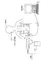
図1は、本発明に係る生体内画像表示装置及び受信システムの好適な実施の形態である無線型被検体内情報取得システムの全体構成を示す模式図である。図1において、無線型被検体内情報取得システムは、被検体1内に導入され、生体内画像(体腔内画像)を撮像して受信システム7に対して画像信号などのデータ送信を行う生体内導入装置としてのカプセル型内視鏡3と、被検体1内に導入されるカプセル型内視鏡3から送信される無線信号の受信処理に用いられる受信システム7とを備える。
(Embodiment 1)
FIG. 1 is a schematic diagram showing an overall configuration of a wireless in-vivo information acquiring system which is a preferred embodiment of an in-vivo image display apparatus and receiving system according to the present invention. In FIG. 1, a wireless in-vivo information acquiring system is introduced into a
カプセル型内視鏡3は、被検体1の口腔を介して被検体1内部に導入され、たとえば内蔵の撮像機構によって取得した体腔内画像データを被検体1の外部に対して無線送信する機能を有する。受信機2は、被検体1の対外表面の適宜位置に分散させて固定的に貼付される複数の受信用アンテナA1〜Anを有したアンテナユニット2aと、複数の受信用アンテナA1〜Anを介して受信される無線信号の処理などを行う受信本体ユニット2bとを備え、これらユニットはコネクタなどを介して着脱可能に接続される。なお、受信用アンテナA1〜Anのそれぞれは、たとえば被検体1が着用可能なジャケットに備え付けられ、被検体1は、このジャケットを着用することによって受信用アンテナA1〜Anを装着するようにしてもよい。また、この場合、受信用アンテナA1〜Anは、ジャケットに対して着脱可能なものであってもよい。
The
また、本実施の形態の無線型被検体内情報取得システムは、受信機2が受信した映像信号に基づいて体腔内画像を表示する表示装置たとえばワークステーション(WS)4と、受信機2とワークステーション4との間でデータの受け渡しを行うための記憶部としての携帯型記録媒体5とを備える。 In addition, the wireless in-vivo information acquiring system according to the present embodiment includes a display device that displays an image in the body cavity based on the video signal received by the receiver 2, for example, a workstation (WS) 4, the receiver 2, and the workpiece. A portable recording medium 5 as a storage unit for transferring data to and from the station 4 is provided.
ワークステーション4は、カプセル型内視鏡3によって撮像された体腔内画像などを表示するためのものであり、携帯型記録媒体5等によって得られるデータに基づいて画像表示を行う。具体的には、ワークステーション4は、CRTディスプレイ、液晶ディスプレイなどによって直接画像を表示する構成としてもよいし、プリンタなどのように、他の媒体に画像を出力する構成としてもよい。
The workstation 4 is for displaying an in-vivo image taken by the
携帯型記録媒体5は、コンパクトフラッシュ(登録商標)メモリなどが用いられ、受信機2の受信本体ユニット2bおよびワークステーション4に対して着脱可能であって、両者に対して挿着された時に情報の出力または記録が可能な構造を有する。この実施の形態では、携帯型記録媒体5は、たとえば検査前には、ワークステーション4の表示装置に挿着されて検査IDなどの識別情報が記憶され、さらに検査の直前には、受信本体ユニット2bに挿着され、この受信本体ユニット2bによって、この識別情報が読み出されて受信本体ユニット2b内に登録される。また、カプセル型内視鏡3が被検体1の体腔内を移動している間は、携帯型記録媒体5は、被検体1に取り付けられた受信本体ユニット2bに挿着されてカプセル型内視鏡3から送信されるデータを記録する。そして、カプセル型内視鏡3が被検体1から排出された後、つまり、被検体1の内部の撮像が終了した後には、受信本体ユニット2bから取り出されてワークステーション4に挿着され、このワークステーション4によって、携帯型記録媒体5に記録されたデータが読み出される構成を有する。たとえば、受信本体ユニット2bとワークステーション4とのデータの受け渡しを、携帯型記録媒体5によって行うことで、被検体1が体腔内の撮影中に自由に動作することが可能となり、また、ワークステーション4との間におけるデータの受け渡し期間の短縮にも寄与している。なお、受信本体ユニット2bとワークステーション4との間のデータの受け渡しは、受信本体ユニット2bに内蔵型の他の記録装置、たとえばハードディスクを用い、ワークステーション4との間におけるデータの受け渡しのために、双方を有線又は無線接続するように構成してもよい。
The portable recording medium 5 uses a compact flash (registered trademark) memory or the like, is detachable from the receiving main unit 2b of the receiver 2 and the workstation 4, and is information when inserted into both. Has a structure capable of outputting or recording. In this embodiment, the portable recording medium 5 is inserted into the display device of the workstation 4 and stored with identification information such as an inspection ID before the inspection, for example. The identification information is read and registered in the reception main unit 2b by the reception main unit 2b. While the
図2は、受信システム7の概略構成の一例を示す概略構成図である。図において、受信システム7は、被検体1に携帯された状態で使用され、受信した無線信号の受信処理を行う受信機2を含む複数の受信機、実施の形態では、たとえば3台の受信機A〜Cと、これら受信機A〜Cと無線によって電気的に接続され、各受信機から出力される無線信号に基づきカプセル型内視鏡3で撮像された画像の表示を行う生体内画像表示装置としてのビュワ6とを備える。これら受信機A〜Cは、図3に示すような同一の構成からなり、たとえば集団検診などで異なる被検体内に導入された異なるカプセル型内視鏡3からの無線信号をそれぞれ受信して、各無線信号の受信処理を行う。すなわち、受信機は、複数のアンテナのうちのたとえば受信強度が最も強いアンテナ21を介してカプセル型内視鏡からの無線信号を受信し、復調部22で復調処理を行い、無線信号に基づいて復調された映像信号を信号処理部23で信号処理(一般的な画像処理の他に、たとえば色強調処理、ホワイトバランスなどを含む)を行って画像データとした後、画像圧縮部24で画像圧縮を行って画像メモリ25に記憶するという通常の構成の他に、本実施の形態にかかる受信機は、画像圧縮部24で圧縮された画像データを変調部26で変調して、無線送信部27から送信用のアンテナ28を介して無線信号として送信するという構成が備えられている。これにより、被検体1は1台の受信機のみを携帯することが可能となる。
FIG. 2 is a schematic configuration diagram illustrating an example of a schematic configuration of the reception system 7. In the figure, a receiving system 7 is used while being carried by a
ビュワ6は、各受信機A〜Cから送信される無線信号を受信し、各無線信号に基づきカプセル型内視鏡で撮像された体腔内画像を画像表示部61に順次表示する。このビュワ6は、操作者が手で把持可能な程度の大きさに形成された可搬型のもので、受信機A〜Cから送信される無線信号を直接的に受信するための機能と、この無線信号に基づく画像を表示する機能を有する。係る機能を実現するために、ビュワ6は、一体に形成されるロッド状の受信用アンテナ31と、画像表示用の小型LCD(液晶表示装置)による画像表示部61を備える。ここで、受信機A〜Cの識別は、各受信機の出力周波数を異なる周波数に設定して、受信側でこの出力周波数から各受信機を特定しても良いし、ワイヤレスLANのような送受信の構成にして、各受信機からの信号に識別用のパラメータを加えて、各受信機を特定しても良い。また、62は、画像選択手段としての画像選択用ボタンで、63は、表示モードを切り替える表示モード切替手段としての切替スイッチである。
The
図4は、実施の形態1にかかるビュワ6の機能構成を示すブロック図である。図において、ビュワ6は、アンテナ31を介して受信した各受信機A〜Cからの無線信号を復調する復調部32と、復調された無線信号に基づく映像信号を伸長する画像伸長部33と、伸長された映像信号の信号処理を行って画像データとして画像メモリ35に記憶させる信号処理部34と、画像データをパラメータと関連付けて順次記憶する画像メモリ35と、画像メモリ35に記憶された画像データの表示処理を行う表示処理部36と、表示処理部36で表示処理された各画像を表示する画像表示部37とを備える。また、ビュワ6は、復調部32で復調された各受信機A〜Cからの無線信号に含まれる所定のパラメータを検知するパラメータ検知部38と、この検知されたパラメータに基づいて、対応する画像を選択するための指示を行う画像選択手段39と、受信機から受信した画像データの表示モードを切り替える表示モード切替手段40とを備え、各画像のいわゆるマルチ画面による複数画像のマルチ表示および順次一画像のいわゆる一画面によるリアルタイム表示を可能にする。
FIG. 4 is a block diagram of a functional configuration of the
パラメータ検知部38は、復調部32で復調された無線信号から、たとえば各患者に特有の識別情報である検査IDや患者IDなどのパラメータを検知している。画像選択手段39は、画像選択用ボタン62を含み、所定の画像を選択するための画像選択用ボタン62が押下されると、パラメータ検知部38によって検知されたパラメータのうちから選択された所定の画像に対応したパラメータを選択する。
The
表示処理部36は、切替スイッチ63の押下によりリアルタイム画面の表示モードに切り替えて、画像選択手段39によって選択されたパラメータに基づき、リアルタイムの画像表示を画像表示部37に行わせる。画像表示部37は、表示処理部36の制御により、初期状態では図2に示すように、受信機Aから受信した画像データを第1の表示領域61b1に表示し、受信機Aとは異なる受信機B,Cから受信した画像データを第2の表示領域61b2,61b3に表示する、マルチ画面の表示を行う。また、画像表示部37は、画像選択が行われると、図5に示すように、選択された画像をリアルタイム表示部としての画像表示領域61aに拡大して順次表示する、一画面のリアルタイム表示を行う。なお、本発明では、画像選択用ボタン63の代わりに、画像表示部37をタッチパネルで形成し、このタッチパネルに表示された所定の画像を触れることによって画像を選択する指示を行うように構成することも可能である。
The
次に、ビュワ6による画像表示の動作を図6のフローチャートを用いて説明する。図において、表示処理部36は、アンテナ31で受信し、画像メモリ35に記憶された各受信機A〜Cからの複数の画像を、マルチ画面で表示する(ステップS101)。この場合には、所定時間内に撮像された各受信機A〜Cからの画像を、図2に示すように、画像表示部37の各表示領域61b1〜61b3に、たとえば静止画像として順次表示させる。表示処理部36では、予め各受信機A〜Cと、各受信機A〜Cが送信するパラメータとを関連付けて記憶しており、パラメータ検知部38で検知された各パラメータによって、各受信機A〜Cと、各受信機A〜Cが送信した画像とを対応付けることが可能となる。
Next, the image display operation by the
次に、表示モード切替手段40の切替スイッチ63が押下されて、画像選択用ボタン63によって受信機A〜Cからの画像のうち、所定の画像が選択されることで、一画面の表示モードの指示があると(ステップS102)、画像選択手段39は、パラメータ検知部38が検知したパラメータのうちから上記所定の画像に対応したパラメータを選択する(ステップS103)。
Next, when the change-
画像選択手段39によってパラメータの選択がなされると、表示処理部36は、この選択されたパラメータに基づく所定の画像を画像メモリ35から選択し(ステップS104)、選択した所定の画像を画像表示部37の画像表示領域61aに一画面でリアルタイム表示させる(ステップS105)。また、次に表示モード切替手段40の切替スイッチ63が押下されると、表示処理部36は、マルチ画面の表示と判断して(ステップS102)、受信した画像をマルチ画面で画像表示部37に表示させる(ステップS101)。なお、この実施の形態では、患者に携帯された受信機からカプセル型内視鏡の無線信号を間接的に受信するように構成したが、ビュワ6は、受信機を介さずにカプセル型内視鏡から直接無線信号を受信するように構成することも可能である。
When the parameter is selected by the image selection means 39, the
このように、この実施の形態では、画像表示部37が第1の受信機Aから受信した第1のカプセル型内視鏡の画像データを表示し得る第1の表示領域61b1と、第1の受信機Aと異なる第2の受信機B,Cから受信した第2のカプセル型内視鏡の画像データを表示し得る第2の表示領域61b2,61b3とを有するので、複数のカプセル型内視鏡から送信される複数人の生体内画像を、受信機A〜Cを介して1台のビュワで受信して観察することができ、これにより被検体内における各カプセル型内視鏡の位置を把握することが可能となる。
Thus, in this embodiment, the first display area 61b1 in which the
また、この実施の形態では、受信機A〜Cから直接受信した画像データを順次受信および順次表示することができる画像表示領域61aをさらに有し、必要に応じて画像の切り替え表示を行うので、たとえばマルチ画面の表示を特定の患者の体腔内画像のリアルタイム表示に切り替えて、拡大してリアルタイムで観察することが可能となり、観察精度が高まりビュワ6の利便性が向上するという効果もある。
Further, in this embodiment, it further has an
(実施の形態2)
図7は、実施の形態2にかかるビュワ6の機能構成を示すブロック図である。図において、ビュワ6が実施の形態1のビュワと異なる点は、アンテナ31で受信した無線信号の受信強度を受信強度検出部41で検出し、最も受信強度の強い無線信号に基づく画像を選択してリアルタイム表示するものである。すなわち、受信強度検出部41は、アンテナ31から受信した各受信機からの無線信号の受信強度を検出するもので、パラメータ検知部38は、受信した無線信号からパラメータを検知するものである。この検出された受信強度とパラメータは、アンテナ31で受信された同一の無線信号に対応しており、一画面の表示モードの際に画像選択手段39は、この検出された受信強度のうちの最も強い受信強度に対応する無線信号のパラメータを選択する。表示処理部36は、マルチ画面の表示モードの際には、アンテナ31で受信され、画像メモリ35に記憶された各受信機A〜Cからの複数の画像を、マルチ画面で画像表示部37に表示させる。また、表示処理部36は、一画面の表示モードの際には、受信した各受信機A〜Cからの画像のうちで受信強度が最も強い画像を、画像表示部37に一画面でリアルタイム表示させる。
(Embodiment 2)
FIG. 7 is a block diagram of a functional configuration of the
この実施の形態では、たとえばリアルタイム表示を行いたい特定の患者にビュワ6を近づけることで、その患者が携帯する受信機から受信強度が最も強い無線信号(または患者の被検体1内のカプセル型内視鏡3からの無線信号)を受信することが可能となり、表示処理部36では、画像選択手段39で選択されたパラメータに基づく画像を、画像表示部37に一画面でリアルタイム表示させることができるようになる。なお、この実施の形態では、実施の形態1に示した画像選択用ボタン63を設けて、画像選択用ボタン63による画像選択と受信強度の検出による画像選択とを併用してもよい。
In this embodiment, for example, by bringing the
このように、この実施の形態では、実施の形態1と同様の効果を奏するとともに、一画面の表示モードの際に特定の患者にビュワ6を近づけるだけで、パラメータの選択がなされ、このパラメータに基づく所定の画像を画像表示部37の画像表示領域61aに一画面で拡大してリアルタイム表示することができるので、さらにビュワ6の利便性が向上できる。
As described above, in this embodiment, the same effect as in the first embodiment is obtained, and the parameter is selected only by bringing the
(実施の形態3)
図8は、実施の形態3にかかるビュワ6の概略構成を示す外観図である。実施の形態1では、表示モードの切替スイッチ63が押されると、画像表示部61の画像表示をマルチ画面による表示と一画面によるリアルタイム表示とを切り替て表示させていたが、この実施の形態では、図8に示すように、マルチ画面と一画面の両方の画像表示を同時に行うものである。すなわち、この実施の形態では、たとえば受信機A〜Iから受信した各画像データを第1および第2の表示領域を含む表示領域61bにマルチ画面で表示させるとともに、受信機A〜Iからの画像データのうち、画像選択用ボタン63で選択された画像データが画像表示領域61aにリアルタイム表示される。
(Embodiment 3)
FIG. 8 is an external view illustrating a schematic configuration of the
図9は、実施の形態3にかかるビュワ6の機能構成を示すブロック図である。図において、このビュワ6では、画像表示部61が2つのLCDからなる表示部37a,37bから構成されている。表示処理部36は、リアルタイムの表示処理とマルチ画面の表示処理を行う。すなわち、この表示処理部36は、たとえば表示部37aに対しては画像選択手段39によって指示された画像を、画像メモリ35から順次取り込んで、一画面に拡大する表示処理を行ってリアルタイムで表示させ、表示部37bに対してはマルチ画面による受信機A〜Iから受信した複数の画像を、画像メモリ35から順次取り込んで、マルチ画面に順次表示させる表示処理を行う。
FIG. 9 is a block diagram of a functional configuration of the
この実施の形態では、複数のカプセル型内視鏡からの画像のマルチ画面でのマルチ表示と、選択された画像の一画面のリアルタイム表示とを同時に行うので、被検体内における各カプセル型内視鏡の位置把握と、リアルタイムでの観察を同時に行うことが可能となるので、さらにビュワ6の利便性を向上できる。
In this embodiment, the multi-display on the multi-screen of the images from the plurality of capsule endoscopes and the real-time display of the single screen of the selected image are simultaneously performed. Since it is possible to simultaneously grasp the position of the mirror and observe in real time, the convenience of the
なお、この実施の形態では、2つのLCDからなる表示部を設けてリアルタイム表示とマルチ表示を行ったが、本発明はこれに限らず、たとえば1つのLCDからなる表示部の表示領域を2分割して、一方の表示領域に一画面のリアルタイム表示を行い、他方の表示領域にマルチ表示を行わせてもよい。 In this embodiment, a display unit composed of two LCDs is provided to perform real-time display and multi-display. However, the present invention is not limited to this. For example, the display area of the display unit composed of one LCD is divided into two. Then, one screen real-time display may be performed in one display area, and multi-display may be performed in the other display area.
(実施の形態4)
図10は、実施の形態4にかかるビュワ6の機能構成を示すブロック図である。図において、このビュワ6が実施の形態3と異なる点は、受信した画像のうちから静止画を選択する静止画選択手段42を設け、静止画の表示とリアルタイム表示を切り替える点である。この静止画選択手段42は、たとえば図示しない静止画選択用ボタンからなり、この静止画選択用ボタンの押下によって所定の画像が選択されたことを示すトリガを発生する。画像メモリ35は、受信機から受信した各画像を記憶する画像用記憶領域と、静止画の画像を記憶する静止画用記憶領域とを有し、このトリガが発生すると、該当する画像を画像用記憶領域とは別の静止画用記憶領域に記憶保持する。表示処理部36では、静止画用記憶領域と画像用記憶領域とから、静止画の画像と受信機から受信した画像を別々に取り込んで、たとえば表示部37aには静止画選択手段42で選択された静止画の画像を表示させ、表示部37bには受信した各画像をマルチ画面に順次表示させる。
(Embodiment 4)
FIG. 10 is a block diagram of a functional configuration of the
なお、この実施の形態では、たとえばリアルタイム表示される所定の画像の中から特定の画像を静止画選択手段42で選択して静止画の画像を表示部37aに表示させ、表示部37bではマルチ表示を順次行わせるように設定してもよいし、またマルチ表示される画像を静止画選択手段42で選択して表示部37bにマルチ画面全体を静止画の画像として表示させ、表示部37aではリアルタイム表示を行わせるように設定してもよい。さらに、マルチ表示されている画像の中から特定の画像を選択してその画像のみを静止画の画像として表示部37aに表示させ、表示部37bではマルチ表示を順次行わせように設定することも可能である。
In this embodiment, for example, a specific image is selected from predetermined images displayed in real time by the still image selection means 42 and the still image is displayed on the
このように、この実施の形態では、実施の形態3と同様の効果を奏するとともに、リアルタイム表示とマルチ表示が行われている画像の中から特定の画像を静止画選択手段42で選択することによって、表示処理部36による静止画の表示処理が可能となるので、さらにビュワ6の利便性を向上できる。
As described above, in this embodiment, the same effect as that of the third embodiment is obtained, and a specific image is selected by the still
(実施の形態5)
図11は、実施の形態5にかかるビュワ6の機能構成を示すブロック図である。図において、このビュワ6が実施の形態3と異なる点は、拡大/縮小の表示モードを指示して切り替えるための表示モード切替手段40を設け、表示部37bに指示された拡大画像または縮小画像を切り替え表示させる点である。この表示モード切替手段40は、たとえば図示しない拡大/縮小切替用ボタンからなり、この拡大/縮小切替用ボタンの拡大の押下によって拡大指示がなされると、表示処理部36では、表示部37aにリアルタイム表示された所定の画像の拡大処理を行ってその拡大画像を表示部37bに表示させる。また、この拡大/縮小切替用ボタンの縮小の押下によって縮小指示がなされると、表示処理部36では、表示部37aに表示された画像の縮小処理を行ってその縮小画像を表示部37bに表示させる。なお、表示部37bに表示される画像は、静止画の画像であってもよいし、表示部37aにリアルタイム表示される画像と同一の拡大/縮小処理されたリアルタイムの画像であってもよい。
(Embodiment 5)
FIG. 11 is a block diagram of a functional configuration of the
このように、この実施の形態では、表示部37aにリアルタイム表示されている画像の拡大/縮小を表示モード切替手段40で指示することによって、表示処理部36による拡大/縮小処理された画像の表示が可能となるので、さらにビュワ6の利便性を向上できる。
As described above, in this embodiment, the display
また、この実施の形態では、たとえば図9に示した画像選択手段39をさらに備えることも可能であり、初期状態では表示部37aに一画面のリアルタイム表示を行うとともに、表示部37bにマルチ画面の表示を行い、画像選択手段39で選択された画像に対して、表示モード切替手段40で拡大/縮小の指示を行えるように設定すれば、さらにビュワ6の利便性を向上できる。
In this embodiment, for example, the image selection means 39 shown in FIG. 9 can be further provided. In the initial state, a real-time display of one screen is performed on the
(実施の形態6)
図12は、受信システムの概略構成の他例を示す概略構成図である。図において、受信システムは、たとえば9台の受信機A〜Iと、これら受信機A〜Iと無線によって電気的に接続され、各受信機A〜Iから出力される無線信号を受信する受信機11と、この受信機11によって受信された無線信号を取り込んで所定の信号処理を行うサーバ12と、サーバ12で信号処理された無線信号を送信する送信機13と、送信機13から送信される無線信号に基づき各カプセル型内視鏡で撮像された画像の表示を行うビュワ6とを備え、受信機11、サーバ12および送信機13は、病院などの院内LANを構築している。また、受信機A〜Iは、図2に示した受信機と同一の構成であり、受信機11および送信機13は、信号中継用の一般的な機器なので、ここでは説明を省略する。
(Embodiment 6)
FIG. 12 is a schematic configuration diagram illustrating another example of the schematic configuration of the reception system. In the figure, a receiving system includes, for example, nine receivers A to I and receivers that are electrically connected to these receivers A to I by radio and receive radio signals output from the receivers A to I. 11, a
サーバ12では、図13のブロック図に示すように、受信機11で復調された無線信号に基づく映像信号を入力部51で取り込み、画像伸長部52で伸長処理を行い、さらに画像処理部53で信号処理を行う。この画像処理部53は、一般的な画像処理や、色強調処理、ホワイトバランスなどの処理を行うとともに、マルチ画像生成部53aによって各受信機A〜Iから受信した個々の画像を、マルチ画面化して1つの画像データ(以下、「マルチ画像」という)として生成し、画像メモリ54に記憶させる。この画像メモリ54に記憶されたマルチ画像を取り込んで画像圧縮部55で画像圧縮を行って、出力部56から送信機13に出力している。サーバ12からのマルチ画像は、送信機13で変調されてビュワ6に送信される。
In the
ビュワ6は、図14のブロック図に示すように、アンテナ31を介して受信した無線信号を、復調部32で復調し、画像伸長部33で伸長処理を行った後に、伸長された映像信号を信号処理部34で信号処理を行って一画面のマルチ画像のデータとして画像メモリ35に記憶させる。さらに、画像メモリ35に記憶されたマルチ画像は、表示処理部36によって取り込まれて表示処理された後、各マルチ画像が画像表示部37で表示される。
As shown in the block diagram of FIG. 14, the
このように、この実施の形態では、たとえば集団検診などで複数の異なるカプセル型内視鏡から送信された画像データを、院内LANを介してビュワ6に送信して、マルチ画面による画像表示を可能とするので、複数のカプセル型内視鏡から送信される複数人の生体内画像を、1台のビュワで受信して観察することができ、これにより被検体内における各カプセル型内視鏡の位置を把握することが可能となる。
As described above, in this embodiment, image data transmitted from a plurality of different capsule endoscopes, for example, in a mass examination, can be transmitted to the
また、この実施の形態では、異なるカプセル型内視鏡から送信された画像データを、サーバ12で取り込んでマルチ画面化して1つの画像データに生成し、その画像データをビュワ6に送信して、マルチ画面による画像表示を可能とするので、各受信機から画像データを別々に受信してマルチ画面化の処理をビュワで行う場合に比べて、ビュワのメモリ量を大幅に削減することができ、受信システムのコスト削減が図られる。
Further, in this embodiment, image data transmitted from different capsule endoscopes is captured by the
なお、本発明では、上記の実施の形態の他に、たとえば検査対象の臓器内にカプセル型内視鏡が移動したことを、受信システムで確認し、ビュワから画像を選択すると、たとえば病院から外出の許可を受信機に送信して患者に認識させるように構成することも可能である。この場合には、患者は、カプセル型内視鏡が排出されるまでの観察期間であっても、不自由を被ることなくさらに自由に行動が可能になる。 In the present invention, in addition to the above embodiment, for example, when the receiving system confirms that the capsule endoscope has moved into the organ to be examined, and selects an image from the viewer, for example, the user goes out of the hospital. It is also possible to send the permission to the receiver so that the patient can recognize it. In this case, the patient can move more freely without suffering inconvenience even during the observation period until the capsule endoscope is discharged.
また、本発明では、静止画、拡大、縮小、マルチ画面化の処理以外に、たとえば画像の色強調、構造強調などの処理を行い、これらの処理を行った画像をビュワの別々の画面に表示させることも可能である。この場合には、画像処理の異なる複数の画像を表示させることが可能となり、観察精度が高まりさらにビュワ6の利便性が向上できる。
In addition, in the present invention, in addition to processing of still images, enlargement, reduction, and multi-screen processing, for example, processing such as image color enhancement and structure enhancement is performed, and images subjected to these processing are displayed on separate screens of the viewer. It is also possible to make it. In this case, it is possible to display a plurality of images with different image processing, and the observation accuracy is improved and the convenience of the
1 被検体
2,A〜I 受信機
2a アンテナユニット
2b 受信本体ユニット
3 カプセル型内視鏡
4 ワークステーション
5 携帯型記録媒体
6 ビュワ
7 受信システム
11 受信機
12 サーバ
13 送信機
21,28,31,A1〜An アンテナ
22,32 復調部
23,34 信号処理部
24,55 画像圧縮部
25,35,54 画像メモリ
26 変調部
27 無線送信部
33,55 画像伸長部
36 表示処理部
37 画像表示部
37a,37b 表示部
38 パラメータ検知部
39 画像選択手段
40 表示モード切替手段
41 受信強度検出部
42 静止画選択手段
51 入力部
52 画像伸長部
53a マルチ画像生成部
56 出力部
61 画像表示部
61a 画像表示領域
61b1 第1の表示領域
61b2,61b3 第2の表示領域
62 切替スイッチ
63 画像選択用ボタン
DESCRIPTION OF
Claims (9)
前記受信部が受信した前記第1の画像情報に対応する第1の画像及び前記第2の画像情報に対応する第2の画像を表示可能な画像表示部と、 An image display unit capable of displaying a first image corresponding to the first image information received by the receiving unit and a second image corresponding to the second image information;
を備えることを特徴とする生体内画像表示装置。An in-vivo image display device comprising:
前記受信部が受信した前記第1または第2の画像情報と前記静止画選択手段が選択した前記画像情報とを各々別の記憶領域に記憶する記憶部と、
前記生体内導入装置から直接的または間接的に前記受信部が識別可能に受信した前記第1または第2の画像情報に対応する前記第1または第2の画像を順次表示する表示モードと、前記静止画選択手段が選択した前記画像情報に対応する画像を静止画表示する表示モードとを切り替える表示モード切替部と、
をさらに備えることを特徴とする請求項1に記載の生体内画像表示装置。 Still image selection means for selecting image information to be displayed as a still image from the first or second image information received by the receiving unit ;
A storage unit for storing said image information said receiver receives the first or second image information and the still picture selecting means selects each separate storage area,
The first or second images sequentially following table Shimesuru display mode corresponding to the previous SL said first or second image information directly or indirectly the receiving unit from the biological introduction apparatus receives distinguishably A display mode switching unit that switches between a display mode for displaying a still image of an image corresponding to the image information selected by the still image selection unit ;
The in- vivo image display device according to claim 1 , further comprising:
前記第1の生体内導入装置が無線送信した前記第1の画像情報を受信し、該第1の画像情報を前記生体内画像表示装置に送信する第1の無線機と、
前記第2の生体内導入装置が無線送信した前記第2の画像情報を受信し、該第2の画像情報を前記生体内画像表示装置に送信する第2の無線機と、
を備えることを特徴とする受信システム。 The in-vivo image display device according to any one of claims 1 to 7,
A first wireless device that receives the first image information wirelessly transmitted by the first in-vivo introduction device and transmits the first image information to the in-vivo image display device;
A second wireless device that receives the second image information wirelessly transmitted by the second in-vivo introduction device and transmits the second image information to the in-vivo image display device;
A receiving system comprising:
前記第2の無線機は、前記第2の画像情報に対応する識別情報を前記生体内画像表示装置に無線送信し、
前記生体内画像表示装置は、前記第1または第2の無線機から受信した識別情報を検知し、
検知した前記識別情報に基づいて、前記第1の画像または前記第2の画像の表示領域を決定することを特徴とする請求項8に記載の受信システム。 The first wireless device wirelessly transmits identification information corresponding to the first image information to the in-vivo image display device;
The second wireless device wirelessly transmits identification information corresponding to the second image information to the in-vivo image display device,
The in-vivo image display apparatus detects the first or second radio or we received identification information,
The receiving system according to claim 8 , wherein a display area of the first image or the second image is determined based on the detected identification information .
Priority Applications (6)
| Application Number | Priority Date | Filing Date | Title |
|---|---|---|---|
| JP2005372670A JP5096676B2 (en) | 2005-12-26 | 2005-12-26 | In-vivo image display device and receiving system |
| AU2006329367A AU2006329367B2 (en) | 2005-12-26 | 2006-12-21 | In vivo image display device and receiving system |
| EP06835090.9A EP1967124B1 (en) | 2005-12-26 | 2006-12-21 | In vivo image display apparatus and receiving system |
| PCT/JP2006/325529 WO2007074712A1 (en) | 2005-12-26 | 2006-12-21 | In vivo image display device and receiving system |
| CN200680049379.9A CN101346094B (en) | 2005-12-26 | 2006-12-21 | In vivo image display system |
| US12/146,222 US8920310B2 (en) | 2005-12-26 | 2008-06-25 | In-vivo image display apparatus and receiving system |
Applications Claiming Priority (1)
| Application Number | Priority Date | Filing Date | Title |
|---|---|---|---|
| JP2005372670A JP5096676B2 (en) | 2005-12-26 | 2005-12-26 | In-vivo image display device and receiving system |
Publications (3)
| Publication Number | Publication Date |
|---|---|
| JP2007167555A JP2007167555A (en) | 2007-07-05 |
| JP2007167555A5 JP2007167555A5 (en) | 2009-01-22 |
| JP5096676B2 true JP5096676B2 (en) | 2012-12-12 |
Family
ID=38217933
Family Applications (1)
| Application Number | Title | Priority Date | Filing Date |
|---|---|---|---|
| JP2005372670A Expired - Fee Related JP5096676B2 (en) | 2005-12-26 | 2005-12-26 | In-vivo image display device and receiving system |
Country Status (6)
| Country | Link |
|---|---|
| US (1) | US8920310B2 (en) |
| EP (1) | EP1967124B1 (en) |
| JP (1) | JP5096676B2 (en) |
| CN (1) | CN101346094B (en) |
| AU (1) | AU2006329367B2 (en) |
| WO (1) | WO2007074712A1 (en) |
Families Citing this family (8)
| Publication number | Priority date | Publication date | Assignee | Title |
|---|---|---|---|---|
| US20080103359A1 (en) * | 2006-10-26 | 2008-05-01 | Tah-Yoong Lin | Capsule-type endoscopic system with real-time image display |
| JP4956287B2 (en) * | 2007-06-06 | 2012-06-20 | オリンパスメディカルシステムズ株式会社 | Capsule endoscope system and program |
| JP5340566B2 (en) * | 2007-07-24 | 2013-11-13 | オリンパスメディカルシステムズ株式会社 | Receiver |
| US8585617B2 (en) * | 2009-12-21 | 2013-11-19 | Nyxoah SA | Diagnosis and prediction of obstructive sleep apnea |
| EP2755385B1 (en) * | 2011-09-09 | 2016-11-02 | Olympus Corporation | Wireless video transmission system and transmission device |
| WO2018008195A1 (en) * | 2016-07-05 | 2018-01-11 | オリンパス株式会社 | Image processing device, image processing system, method for operating image processing device, and program for operating image processing device |
| DE112017005227T5 (en) * | 2016-10-14 | 2019-07-11 | Olympus Corporation | Receiving antenna, receiving antenna unit, receiving system and receiving device |
| CN109480746A (en) * | 2019-01-14 | 2019-03-19 | 深圳市资福医疗技术有限公司 | Intelligent control capsule endoscopic is in alimentary canal different parts working method and device |
Family Cites Families (24)
| Publication number | Priority date | Publication date | Assignee | Title |
|---|---|---|---|---|
| JPS6048011A (en) * | 1983-08-27 | 1985-03-15 | Olympus Optical Co Ltd | Endoscope device |
| JP3461499B2 (en) * | 1991-03-11 | 2003-10-27 | オリンパス光学工業株式会社 | Image processing device |
| IL108352A (en) * | 1994-01-17 | 2000-02-29 | Given Imaging Ltd | In vivo video camera system |
| JP3631265B2 (en) | 1994-04-27 | 2005-03-23 | オリンパス株式会社 | In-vivo observation device |
| CN2303580Y (en) * | 1997-08-14 | 1999-01-13 | 张恒 | Digital medical endoscope monitoring instrument |
| US6853310B2 (en) * | 1999-12-29 | 2005-02-08 | Ge Medical Systems Information Technologies, Inc. | Tri-mode medical telemetry antenna system |
| JP2001353124A (en) * | 2000-04-10 | 2001-12-25 | Olympus Optical Co Ltd | Endoscopic apparatus |
| IL143260A (en) | 2001-05-20 | 2006-09-05 | Given Imaging Ltd | Array system and method for locating an in vivo signal source |
| US6951536B2 (en) * | 2001-07-30 | 2005-10-04 | Olympus Corporation | Capsule-type medical device and medical system |
| JP2003135371A (en) | 2001-10-31 | 2003-05-13 | Olympus Optical Co Ltd | Endoscopic system |
| WO2003069913A1 (en) * | 2002-02-12 | 2003-08-21 | Given Imaging Ltd. | System and method for displaying an image stream |
| JP2003325439A (en) * | 2002-05-15 | 2003-11-18 | Olympus Optical Co Ltd | Capsule type medical treatment device |
| JP2004024340A (en) | 2002-06-21 | 2004-01-29 | Olympus Corp | Endoscope equipment |
| JP2004121613A (en) | 2002-10-03 | 2004-04-22 | Olympus Corp | Medical controlling device |
| JP2004113780A (en) | 2002-09-06 | 2004-04-15 | Pentax Corp | Endoscope and optical tomographic endoscope system |
| JP2004275321A (en) * | 2003-03-14 | 2004-10-07 | Fuji Photo Optical Co Ltd | Electronic endoscope apparatus |
| EP2263513B1 (en) * | 2003-06-24 | 2013-08-07 | Olympus Corporation | Capsule type medical device communication system, capsule type medical device, and biological information reception device |
| JP2005021392A (en) * | 2003-07-02 | 2005-01-27 | Olympus Corp | Endoscope system |
| ATE538445T1 (en) * | 2003-07-02 | 2012-01-15 | Given Imaging Ltd | IMAGING SENSOR ARRAY AND DEVICE FOR USE AND METHOD THEREOF |
| JP4675241B2 (en) * | 2003-12-01 | 2011-04-20 | オリンパス株式会社 | Endoscope system |
| CN1554310A (en) * | 2003-12-24 | 2004-12-15 | 孙志宏 | Intelligent oral administration full digestive tract endoscope |
| JP2005245937A (en) * | 2004-03-08 | 2005-09-15 | Pentax Corp | Clothing with communication function and endoscope system |
| JP4885518B2 (en) * | 2005-11-10 | 2012-02-29 | オリンパス株式会社 | Capsule type endoscope system and capsule type endoscope information processing method |
| JP2008307122A (en) * | 2007-06-12 | 2008-12-25 | Olympus Corp | In vivo information acquisition apparatus |
-
2005
- 2005-12-26 JP JP2005372670A patent/JP5096676B2/en not_active Expired - Fee Related
-
2006
- 2006-12-21 CN CN200680049379.9A patent/CN101346094B/en not_active Expired - Fee Related
- 2006-12-21 WO PCT/JP2006/325529 patent/WO2007074712A1/en active Application Filing
- 2006-12-21 EP EP06835090.9A patent/EP1967124B1/en not_active Expired - Fee Related
- 2006-12-21 AU AU2006329367A patent/AU2006329367B2/en not_active Ceased
-
2008
- 2008-06-25 US US12/146,222 patent/US8920310B2/en not_active Expired - Fee Related
Also Published As
| Publication number | Publication date |
|---|---|
| WO2007074712A1 (en) | 2007-07-05 |
| JP2007167555A (en) | 2007-07-05 |
| US8920310B2 (en) | 2014-12-30 |
| US20080262298A1 (en) | 2008-10-23 |
| EP1967124A4 (en) | 2012-06-20 |
| EP1967124B1 (en) | 2015-01-28 |
| CN101346094B (en) | 2010-11-17 |
| AU2006329367B2 (en) | 2010-04-01 |
| EP1967124A1 (en) | 2008-09-10 |
| CN101346094A (en) | 2009-01-14 |
| AU2006329367A1 (en) | 2007-07-05 |
Similar Documents
| Publication | Publication Date | Title |
|---|---|---|
| JP4823659B2 (en) | In vivo image display device | |
| JP5096676B2 (en) | In-vivo image display device and receiving system | |
| JP4789607B2 (en) | Receiver | |
| JP2007167555A5 (en) | ||
| JP4015666B2 (en) | In-subject information acquisition system | |
| JP4847075B2 (en) | Receiver | |
| US20080103382A1 (en) | Image Display Apparatus | |
| JP4823614B2 (en) | Portable simple image display device and receiving system | |
| US8135371B2 (en) | Receiving apparatus and receiving system | |
| CN212853421U (en) | Capsule endoscope system | |
| JP4734068B2 (en) | Body cavity image observation device | |
| JP4602822B2 (en) | In-subject information acquisition system | |
| JP4827486B2 (en) | Wireless in-vivo information acquisition system | |
| JP2005245596A (en) | Antenna accommodating apparatus and antenna testing system | |
| JP4009610B2 (en) | Receiver | |
| JP2005218703A (en) | Receiving apparatus | |
| JP2005277740A (en) | Receiver | |
| JP2006320649A (en) | Receiving device and receiving system | |
| JP2005319095A (en) | Receiver | |
| JP2005218704A (en) | Receiving apparatus |
Legal Events
| Date | Code | Title | Description |
|---|---|---|---|
| A521 | Request for written amendment filed |
Free format text: JAPANESE INTERMEDIATE CODE: A523 Effective date: 20081203 |
|
| A621 | Written request for application examination |
Free format text: JAPANESE INTERMEDIATE CODE: A621 Effective date: 20081203 |
|
| A131 | Notification of reasons for refusal |
Free format text: JAPANESE INTERMEDIATE CODE: A131 Effective date: 20110802 |
|
| A521 | Request for written amendment filed |
Free format text: JAPANESE INTERMEDIATE CODE: A523 Effective date: 20110930 |
|
| TRDD | Decision of grant or rejection written | ||
| A01 | Written decision to grant a patent or to grant a registration (utility model) |
Free format text: JAPANESE INTERMEDIATE CODE: A01 Effective date: 20120904 |
|
| A01 | Written decision to grant a patent or to grant a registration (utility model) |
Free format text: JAPANESE INTERMEDIATE CODE: A01 |
|
| A61 | First payment of annual fees (during grant procedure) |
Free format text: JAPANESE INTERMEDIATE CODE: A61 Effective date: 20120921 |
|
| R150 | Certificate of patent or registration of utility model |
Free format text: JAPANESE INTERMEDIATE CODE: R150 |
|
| FPAY | Renewal fee payment (event date is renewal date of database) |
Free format text: PAYMENT UNTIL: 20150928 Year of fee payment: 3 |
|
| S111 | Request for change of ownership or part of ownership |
Free format text: JAPANESE INTERMEDIATE CODE: R313115 |
|
| R350 | Written notification of registration of transfer |
Free format text: JAPANESE INTERMEDIATE CODE: R350 |
|
| S531 | Written request for registration of change of domicile |
Free format text: JAPANESE INTERMEDIATE CODE: R313531 |
|
| R350 | Written notification of registration of transfer |
Free format text: JAPANESE INTERMEDIATE CODE: R350 |
|
| LAPS | Cancellation because of no payment of annual fees |