JP4015666B2 - In-subject information acquisition system - Google Patents
In-subject information acquisition system Download PDFInfo
- Publication number
- JP4015666B2 JP4015666B2 JP2005111131A JP2005111131A JP4015666B2 JP 4015666 B2 JP4015666 B2 JP 4015666B2 JP 2005111131 A JP2005111131 A JP 2005111131A JP 2005111131 A JP2005111131 A JP 2005111131A JP 4015666 B2 JP4015666 B2 JP 4015666B2
- Authority
- JP
- Japan
- Prior art keywords
- subject
- information
- receiving
- receiving device
- acquisition system
- Prior art date
- Legal status (The legal status is an assumption and is not a legal conclusion. Google has not performed a legal analysis and makes no representation as to the accuracy of the status listed.)
- Expired - Fee Related
Links
- 239000002775 capsule Substances 0.000 claims description 33
- 238000001514 detection method Methods 0.000 claims description 25
- 238000001727 in vivo Methods 0.000 claims description 15
- 238000003384 imaging method Methods 0.000 claims description 10
- 230000006870 function Effects 0.000 description 15
- 238000010586 diagram Methods 0.000 description 10
- 238000007689 inspection Methods 0.000 description 6
- 238000006243 chemical reaction Methods 0.000 description 5
- 230000005684 electric field Effects 0.000 description 3
- 230000005540 biological transmission Effects 0.000 description 2
- 241000255777 Lepidoptera Species 0.000 description 1
- 239000002131 composite material Substances 0.000 description 1
- 238000003745 diagnosis Methods 0.000 description 1
- 238000001839 endoscopy Methods 0.000 description 1
- 238000009413 insulation Methods 0.000 description 1
- 239000004973 liquid crystal related substance Substances 0.000 description 1
- 230000006386 memory function Effects 0.000 description 1
- 238000012986 modification Methods 0.000 description 1
- 230000004048 modification Effects 0.000 description 1
- 210000000056 organ Anatomy 0.000 description 1
- 230000002572 peristaltic effect Effects 0.000 description 1
- 210000000813 small intestine Anatomy 0.000 description 1
- 210000002784 stomach Anatomy 0.000 description 1
- 230000009747 swallowing Effects 0.000 description 1
- 210000001835 viscera Anatomy 0.000 description 1
Images


Classifications
-
- A—HUMAN NECESSITIES
- A61—MEDICAL OR VETERINARY SCIENCE; HYGIENE
- A61B—DIAGNOSIS; SURGERY; IDENTIFICATION
- A61B1/00—Instruments for performing medical examinations of the interior of cavities or tubes of the body by visual or photographical inspection, e.g. endoscopes; Illuminating arrangements therefor
- A61B1/00002—Operational features of endoscopes
- A61B1/00011—Operational features of endoscopes characterised by signal transmission
- A61B1/00016—Operational features of endoscopes characterised by signal transmission using wireless means
-
- A—HUMAN NECESSITIES
- A61—MEDICAL OR VETERINARY SCIENCE; HYGIENE
- A61B—DIAGNOSIS; SURGERY; IDENTIFICATION
- A61B1/00—Instruments for performing medical examinations of the interior of cavities or tubes of the body by visual or photographical inspection, e.g. endoscopes; Illuminating arrangements therefor
- A61B1/00002—Operational features of endoscopes
- A61B1/00025—Operational features of endoscopes characterised by power management
- A61B1/00036—Means for power saving, e.g. sleeping mode
-
- A—HUMAN NECESSITIES
- A61—MEDICAL OR VETERINARY SCIENCE; HYGIENE
- A61B—DIAGNOSIS; SURGERY; IDENTIFICATION
- A61B1/00—Instruments for performing medical examinations of the interior of cavities or tubes of the body by visual or photographical inspection, e.g. endoscopes; Illuminating arrangements therefor
- A61B1/00002—Operational features of endoscopes
- A61B1/00043—Operational features of endoscopes provided with output arrangements
- A61B1/00045—Display arrangement
-
- A—HUMAN NECESSITIES
- A61—MEDICAL OR VETERINARY SCIENCE; HYGIENE
- A61B—DIAGNOSIS; SURGERY; IDENTIFICATION
- A61B1/00—Instruments for performing medical examinations of the interior of cavities or tubes of the body by visual or photographical inspection, e.g. endoscopes; Illuminating arrangements therefor
- A61B1/04—Instruments for performing medical examinations of the interior of cavities or tubes of the body by visual or photographical inspection, e.g. endoscopes; Illuminating arrangements therefor combined with photographic or television appliances
- A61B1/041—Capsule endoscopes for imaging
-
- A—HUMAN NECESSITIES
- A61—MEDICAL OR VETERINARY SCIENCE; HYGIENE
- A61B—DIAGNOSIS; SURGERY; IDENTIFICATION
- A61B1/00—Instruments for performing medical examinations of the interior of cavities or tubes of the body by visual or photographical inspection, e.g. endoscopes; Illuminating arrangements therefor
- A61B1/00112—Connection or coupling means
- A61B1/00121—Connectors, fasteners and adapters, e.g. on the endoscope handle
- A61B1/00124—Connectors, fasteners and adapters, e.g. on the endoscope handle electrical, e.g. electrical plug-and-socket connection
-
- A—HUMAN NECESSITIES
- A61—MEDICAL OR VETERINARY SCIENCE; HYGIENE
- A61B—DIAGNOSIS; SURGERY; IDENTIFICATION
- A61B2560/00—Constructional details of operational features of apparatus; Accessories for medical measuring apparatus
- A61B2560/02—Operational features
- A61B2560/0204—Operational features of power management
- A61B2560/0209—Operational features of power management adapted for power saving
-
- A—HUMAN NECESSITIES
- A61—MEDICAL OR VETERINARY SCIENCE; HYGIENE
- A61B—DIAGNOSIS; SURGERY; IDENTIFICATION
- A61B5/00—Measuring for diagnostic purposes; Identification of persons
- A61B5/07—Endoradiosondes
- A61B5/073—Intestinal transmitters
Landscapes
- Health & Medical Sciences (AREA)
- Life Sciences & Earth Sciences (AREA)
- Surgery (AREA)
- Engineering & Computer Science (AREA)
- Biomedical Technology (AREA)
- Molecular Biology (AREA)
- Pathology (AREA)
- Radiology & Medical Imaging (AREA)
- Nuclear Medicine, Radiotherapy & Molecular Imaging (AREA)
- Biophysics (AREA)
- Physics & Mathematics (AREA)
- Heart & Thoracic Surgery (AREA)
- Medical Informatics (AREA)
- Optics & Photonics (AREA)
- Animal Behavior & Ethology (AREA)
- General Health & Medical Sciences (AREA)
- Public Health (AREA)
- Veterinary Medicine (AREA)
- Computer Networks & Wireless Communication (AREA)
- Endoscopes (AREA)
- Measurement Of The Respiration, Hearing Ability, Form, And Blood Characteristics Of Living Organisms (AREA)
Description
本発明は、被検体内に導入された被検体内導入装置、たとえば飲み込み型のカプセル型内視鏡から無線送信される映像信号を受信および表示する被検体内情報取得システムに関するものである。 The present invention relates to an in-subject information acquisition system that receives and displays a video signal transmitted wirelessly from an in-subject introduction device introduced into a subject, for example, a swallowable capsule endoscope.
近年、内視鏡の分野では、撮像機能と無線通信機能とが装備されたカプセル型内視鏡が登場している。このカプセル型内視鏡は、観察(検査)のために被検体である被検者の口から飲み込まれた後、被検者の生体から自然排出されるまでの観察期間、たとえば胃、小腸などの臓器の内部(体腔内)をその蠕動運動に伴って移動し、撮像機能を用いて順次撮像する構成を有する。 In recent years, in the field of endoscopes, capsule endoscopes equipped with an imaging function and a wireless communication function have appeared. This capsule endoscope is an observation period after it is swallowed from the subject's mouth, which is a subject for observation (examination), until it is naturally discharged from the subject's body, for example, the stomach, the small intestine, etc. The internal organs (inside the body cavity) move with the peristaltic movement, and images are sequentially captured using the imaging function.
また、これら臓器内を移動するこの観察期間、カプセル型内視鏡によって体腔内で撮像された画像データは、順次無線通信などの無線通信機能により、被検体の外部に送信され、外部の受信装置内に設けられたメモリに蓄積される。被検者がこの無線通信機能とメモリ機能を備えた受信装置を携帯することにより、被検者は、カプセル型内視鏡を飲み込んだ後、排出されるまでの観察期間であっても、不自由を被ることなく自由に行動が可能になる。観察後は、医者もしくは看護士によって、受信装置のメモリに蓄積された画像データに基づいて、体腔内の画像をディスプレイなどの表示手段に表示させて診断を行うことができる。 Also, during this observation period of moving through these organs, image data imaged in the body cavity by the capsule endoscope is sequentially transmitted to the outside of the subject by a wireless communication function such as wireless communication, and an external receiving device It is stored in a memory provided in the inside. When the subject carries the receiving device equipped with the wireless communication function and the memory function, the subject is incapable of performing the observation even during the observation period from swallowing the capsule endoscope until it is discharged. It is possible to act freely without incurring freedom. After the observation, a doctor or a nurse can make a diagnosis by displaying an image in the body cavity on a display means such as a display based on the image data stored in the memory of the receiving device.
一般に、受信装置は、カプセル型内視鏡から送信される映像信号を受信するための複数のアンテナを被検体外部に分散配置し、映像信号の受信誤りが少ない1つのアンテナを選択切り替えして受信するようにしている。なお、特許文献1には、被検体外部に配置された複数のアンテナの受信切り替えを行い、各アンテナが受信する電界強度に基づいて、映像信号の発信源である被検体内のカプセル型内視鏡の位置を探知する受信機が記載されている。
In general, a receiving device distributes and arranges a plurality of antennas for receiving a video signal transmitted from a capsule endoscope outside a subject, and selectively switches and receives one antenna with few video signal reception errors. Like to do. In
しかしながら、この受信装置は、小型のディスプレイを有し、受信した映像信号やカプセル型内視鏡の位置情報を、このディスプレイに表示させるものがあり、この場合には、受信装置自体が大きくて重いものとなり、被検者がこの受信装置を携帯することになると、被検者に大きな負担をかけるという問題があった。さらに、このような受信装置では、ディスプレイの表示、画像処理および位置情報の算出などの制御のために、電力消費が大きくなってしまうという問題もあった。また、受信装置を、ディスプレイを有するワークステーションに接続し、受信装置で得られた映像信号やカプセル型内視鏡の位置情報を、このワークステーションに送信してディスプレイに表示させるものもあるが、この場合には、たとえばカプセル型内視鏡からの受信情報を迅速に見たい時に対応できないという問題があった。また、被検者に受信装置が装着された状態で、ワークステーションに接続すると、被検者に装着されたアンテナと大地が接続されることとなり、絶縁対策が必要となるという問題もあった。 However, this receiving device has a small display, and there is a device that displays the received video signal and the position information of the capsule endoscope on this display. In this case, the receiving device itself is large and heavy. Therefore, when the subject carries the receiving apparatus, there is a problem that a heavy burden is placed on the subject. In addition, such a receiving apparatus has a problem that power consumption increases due to controls such as display on the display, image processing, and calculation of position information. In addition, there is a type in which the receiving device is connected to a workstation having a display, and the video signal obtained by the receiving device and the position information of the capsule endoscope are transmitted to the workstation and displayed on the display. In this case, for example, there is a problem that it is not possible to respond when it is desired to quickly view information received from the capsule endoscope. In addition, when the receiving device is attached to the subject and connected to the workstation, the antenna attached to the subject and the ground are connected, and there is a problem that an insulation measure is required.
本発明は、上記問題に鑑みてなされたものであって、受信装置の小型・軽量化を図るとともに、低消費電力化を図ることができる被検体内情報取得システムを提供することを目的とする。 The present invention has been made in view of the above problems, and an object of the present invention is to provide an in-vivo information acquisition system capable of reducing the size and weight of a receiving apparatus and reducing power consumption. .
また、本発明の他の目的は、迅速、かつリアルタイムにカプセル型内視鏡から取得した被検体内情報などの必要な情報を表示することができる被検体内情報取得システムを提供することにある。 Another object of the present invention is to provide an in-subject information acquisition system capable of displaying necessary information such as in-subject information acquired from a capsule endoscope quickly and in real time. .
上述した課題を解決し、目的を達成するために、本発明にかかる被検体内情報取得システムは、被検体内導入装置から無線送信される被検体内情報を受信する受信装置と、前記被検体内情報を取り込んで表示部に表示する小型表示装置とを有する被検体内情報取得システムにおいて、前記受信装置と前記小型表示装置を通信可能に接続する通信手段を、備え、前記受信装置は、少なくとも前記被検体内情報を前記通信手段を介して、前記小型表示装置に出力し、前記小型表示装置は、前記通信手段による前記受信装置との接続を検知する検知手段と、前記検知手段の検知結果に基づいて、前記表示部の表示を、前記通信手段を介して取り込んだ前記被検体内情報の表示に切り替える切替制御手段と、を備えることを特徴とする。 In order to solve the above-described problems and achieve the object, an in-subject information acquisition system according to the present invention includes a receiving device that receives in-subject information wirelessly transmitted from an in-subject introduction device, and the subject In an in-vivo information acquisition system having a small display device that captures internal information and displays it on a display unit, the in-subject information acquisition system includes a communication unit that connects the receiving device and the small display device so that they can communicate with each other. The in-vivo information is output to the small display device via the communication means, and the small display device detects a connection with the receiving device by the communication means, and a detection result of the detection means Switching control means for switching the display on the display unit to the display of the in-subject information captured via the communication means.
また、請求項2の発明にかかる被検体内情報取得システムは、被検体内導入装置から無線送信される被検体内情報を受信する受信装置と、前記被検体内情報を取り込んで表示部に表示する小型表示装置とを有する被検体内情報取得システムにおいて、前記受信装置と前記小型表示装置を通信可能に接続する通信手段を、備え、前記受信装置は、少なくとも前記被検体内情報を前記通信手段を介して、前記小型表示装置に出力し、前記小型表示装置は、前記通信手段による前記受信装置との接続を検知する検知手段と、前記被検体内導入装置から無線送信される被検体内情報を受信する無線手段と、前記検知手段による検知結果に基づいて、前記無線手段または前記通信手段による受信動作を切り替え制御する切替制御手段と、を備えることを特徴とする。 An in-subject information acquisition system according to a second aspect of the invention includes a receiving device that receives in-subject information wirelessly transmitted from an in-subject introduction device, and the in-subject information is captured and displayed on a display unit. An in-subject information acquisition system having a small display device that includes communication means for communicatively connecting the reception device and the small display device, wherein the reception device includes at least the in-subject information as the communication means. The small display device outputs the information to the small display device, the small display device detects the connection with the receiving device by the communication means, and the in-subject information wirelessly transmitted from the in-subject introduction device And a switching control means for switching and controlling a receiving operation by the wireless means or the communication means based on a detection result by the detecting means. And butterflies.
また、請求項3の発明にかかる被検体内情報取得システムは、上記発明において、前記受信装置は、前記被検体内導入装置からの被検体内情報を受信する受信アンテナと、前記受信アンテナの受信強度を検出する受信強度検出手段と、前記受信強度検出手段で検出された受信強度の情報を、前記被検体内情報に重畳する重畳手段と、をさらに備え、前記小型表示装置は、前記受信強度の情報に基づいて、前記被検体内導入装置の位置を解析する解析手段と、前記表示部に表示される情報を指示する指示手段と、をさらに備え、前記切替制御手段は、前記指示手段の指示に応じて、前記表示部に表示させる情報を切り替えることを特徴とする。 The in-subject information acquisition system according to a third aspect of the present invention is the above-described invention, wherein the receiving device receives the in-subject information from the in-subject introduction device and the reception of the reception antenna. A reception intensity detection means for detecting intensity; and a superimposing means for superimposing information on the reception intensity detected by the reception intensity detection means on the in-subject information, wherein the small display device includes the reception intensity. Analysis means for analyzing the position of the intra-subject introduction apparatus based on the information of the above, and instruction means for instructing information displayed on the display unit, wherein the switching control means includes: According to an instruction, the information to be displayed on the display unit is switched.
また、請求項4の発明にかかる被検体内情報取得システムは、上記発明において、前記被検体内導入装置が送信する被検体内情報は、前記被検体内を撮像した映像信号と、前記被検体内導入装置の位置情報とを少なくとも含み、前記小型表示装置は、前記表示部に表示される情報を指示する指示手段を、さらに備え、前記切替制御手段は、前記指示手段の指示に応じて、前記表示部に表示させる情報を切り替えることを特徴とする。 The in-subject information acquisition system according to a fourth aspect of the present invention is the above-described invention, wherein the in-subject information transmitted by the in-subject introduction apparatus includes a video signal obtained by imaging the inside of the subject, and the subject At least the position information of the introduction device, the small display device further comprises an instruction means for instructing information displayed on the display unit, the switching control means according to an instruction from the instruction means, The information displayed on the display unit is switched.
また、請求項5の発明にかかる被検体内情報取得システムは、上記発明において、前記表示部に表示される情報は、前記映像信号、前記被検体内導入装置に関する情報、前記受信装置に関する情報、前記位置情報、前記被検体の検査に関する情報からなり、前記表示部は、前記切替制御手段の表示切り替えによって、これら情報のうち、少なくとも1つの情報を表示することを特徴とする。
In the in-vivo information acquiring system according to the invention of
本発明にかかる被検体内情報取得システムは、受信装置と小型表示装置を通信手段を介して接続し、検知手段が前記通信手段による前記受信装置と小型表示装置との接続を検知すると、受信装置からの被検体内情報を取り込んで、表示部で表示が可能になるように、切替制御手段が表示の切り替えを行うので、受信装置に表示手段が必要なくなるとともに、回路構成が簡単になり、これによって受信装置の小型・軽量化を図るとともに、低消費電力化を図ることができるという効果を奏する。また、本発明にかかる被検体内情報取得システムは、受信装置に接続された小型表示装置によって被検体内情報などの検査に必要な情報を取り込んで表示部に表示するので、迅速、かつリアルタイムにカプセル型内視鏡から取得した被検体内情報などの必要な情報を小型表示装置の表示部に表示させることができる。 The in-vivo information acquiring system according to the present invention connects a receiving device and a small display device via a communication means, and when the detecting means detects a connection between the receiving device and the small display device by the communication means, the receiving device Since the switching control means switches the display so that the in-subject information from the subject can be captured and displayed on the display unit, the receiving device does not need a display means and the circuit configuration is simplified. As a result, the receiving apparatus can be reduced in size and weight, and the power consumption can be reduced. In addition, the in-subject information acquisition system according to the present invention captures information necessary for examination such as in-subject information by a small display device connected to the receiving device and displays the information on the display unit. Necessary information such as in-subject information acquired from the capsule endoscope can be displayed on the display unit of the small display device.
以下に、本発明にかかる被検体内情報取得システムの実施の形態を図1〜図7の図面に基づいて詳細に説明する。なお、本発明は、これらの実施の形態に限定されるものではなく、本発明の要旨を逸脱しない範囲で種々の変更実施の形態が可能である。 Hereinafter, an embodiment of an in-vivo information acquiring system according to the present invention will be described in detail with reference to the drawings of FIGS. The present invention is not limited to these embodiments, and various modifications can be made without departing from the scope of the present invention.
(実施の形態1)
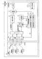
図1は、本発明にかかる被検体内情報取得システムの全体構成を示す模式図である。図1において、無線型被検体内情報取得システムは、無線受信機能を有する受信装置2と、被検体1内に導入され、体腔内画像を撮像して受信装置2に対して映像信号などのデータ送信を行うカプセル型内視鏡(被検体内導入装置)3とを備える。また、無線型被検体内情報取得システムは、受信装置2が受信した映像信号に基づいて体腔内画像を表示する小型表示装置たるビュワー4と、受信装置2と小型表示装置たるビュワー4との間でデータの受け渡しを行うための通信手段としての通信ケーブル5とを備える。受信装置2は、被検体1によって着用される受信ジャケット2aと、受信される無線信号の処理などを行う外部装置2bとを備える。
(Embodiment 1)
FIG. 1 is a schematic diagram showing an overall configuration of an in-vivo information acquiring system according to the present invention. In FIG. 1, a wireless in-vivo information acquiring system includes a receiving device 2 having a wireless receiving function, and a body cavity image that is introduced into the
次に、図2の模式図および図3のブロック図を用いて受信装置の構成について説明する。受信装置2は、カプセル型内視鏡3から無線送信された体腔内の画像データを受信する機能を有する。図2および図3に示すように、受信装置2は、被検体1によって着用可能な形状を有し、受信用アンテナA1〜Anを備えた受信ジャケット2aと、受信ジャケット2aを介して受信された無線信号の処理などを行う外部装置2bとを備える。なお、各受信用アンテナA1〜Anは、直接被検体(人体)1の外表面に貼付して、受信ジャケット2aに備え付けられなくてもよく、また受信ジャケット2aに着脱可能なものでもよい。
Next, the configuration of the receiving apparatus will be described with reference to the schematic diagram of FIG. 2 and the block diagram of FIG. The receiving device 2 has a function of receiving image data in the body cavity that is wirelessly transmitted from the capsule endoscope 3. As shown in FIG. 2 and FIG. 3, the receiving device 2 has a shape that can be worn by the
外部装置2bは、受信された映像信号を、この接続された通信ケーブル5を介して小型表示装置たるビュワー4へ送信している。さらに、この外表面の上面には、受信用アンテナA1〜Anを接続するための接続部CONが設けられている。なお、これら受信用アンテナA1〜Anは、上記接続部CONに接続するコネクタCON1〜CONnを有する。この外部装置2bは、カプセル型内視鏡3から送信された無線信号を2値化して出力する機能を有する。すなわち、外部装置2bは、図3に示すように、各受信用アンテナA1〜Anの接続切り替えを行う切替スイッチSWと、この切替スイッチSWの後段に接続され、切替スイッチSWによって切り替え接続された受信用アンテナA1〜Anからの無線信号を増幅し、復調するチューナー11とを有し、さらにチューナー11の後段には、2値化回路12と、サンプルホールド回路15とが接続される。サンプルホールド回路15の後段には、さらにA/D変換部16が接続される。
The
重畳部13は、重畳手段として2値化回路12で2値化された映像信号に、切替制御部SCからの情報を重畳させ、接続されたインターフェース部14に出力する機能を有する。切替制御部SCは、強度受信アンテナ番号N1および映像受信アンテナ番号N2を有し、これらの番号情報をもとに、切替スイッチSWの切替指示を行うとともに、サンプルホールド回路15、A/D変換部16の処理タイミングを指示する。また、インターフェース部14は、図示しない接続部を介して通信ケーブル5と接続されている。重畳部13は、図示しない内部メモリを有し、外部から入力する検査IDなどの被検者を識別する識別情報をこの内部メモリに登録する。また、重畳部13は、切替制御部SCからの情報を映像信号に重畳させてインターフェース部14に出力している。電力供給部17は、外部装置2bに内蔵された電池からなり、図3に示す電源スイッチ18がオンされることで、上述した各内部機器への電力供給を行う。
The
外部装置2bの切替スイッチSWは、切替制御部SCからの切替指示に基づき、受信用アンテナA1〜Anからの無線信号をチューナー11に出力する。ここで、切替スイッチSWは、受信用アンテナA1〜Anの配置位置にそれぞれ対応して各受信用アンテナA1〜Anを接続するアンテナ切替手段としての接続部CONを有する。
The change-over switch SW of the
さて、図3において、チューナー11は、上述したように、無線信号を増幅し、復調した映像信号S1を2値化回路12に出力するとともに、増幅した無線信号の受信電界強度である受信強度信号S2をサンプルホールド回路15に出力する。2値化回路12によって2値化処理された映像信号は、重畳部13に出力される。サンプルホールド回路15によってサンプルホールドされた受信強度信号は、A/D変換部16によってデジタル信号に変換され、切替制御部SCに取り込まれる。
In FIG. 3, as described above, the
切替制御部SCは、強度受信アンテナ番号N1と映像受信アンテナ番号N2との情報を保持し、強度受信期間には強度受信アンテナ番号N1に対応する受信用アンテナA1〜Anを選択接続するように切替スイッチSWに指示し、映像受信期間には映像受信アンテナ番号N2に対応する受信用アンテナA1〜Anを選択接続するように、切替スイッチSWに指示する信号S5を切替スイッチSWに出力するとともに、サンプルホールド回路15によるサンプルホールドタイミングを指示する信号S3a、A/D変換部16によるA/D変換タイミングを指示する信号S3bを出力する。また、切替制御部SCは、強度受信期間中に取り込んだ強度受信アンテナ番号N1に対応する受信用アンテナA1〜Anの番号の情報と、各受信用アンテナA1〜Anの受信強度の情報を重畳部13に出力する。
The switching control unit SC holds information on the strength receiving antenna number N1 and the video receiving antenna number N2, and switches so as to selectively connect the receiving antennas A1 to An corresponding to the strength receiving antenna number N1 during the strength receiving period. The switch SW is instructed, and during the video reception period, the signal S5 instructing the changeover switch SW is output to the changeover switch SW so as to selectively connect the receiving antennas A1 to An corresponding to the video receiving antenna number N2, and the sample is A signal S3a for instructing sample hold timing by the hold circuit 15 and a signal S3b for instructing A / D conversion timing by the A /
重畳部13は、2値化回路12からの映像信号に、切替制御部SCからの強度受信アンテナ番号N1に対応する受信用アンテナA1〜Anの番号の情報と、各受信用アンテナA1〜Anの受信強度の情報を重畳させてインターフェース部14に出力している。インターフェース部14は、この映像信号を通信ケーブル5を介して小型表示装置たるビュワー4に送信している。なお、本発明にかかる重畳部13は、切替制御部SCからの情報とともに、内部メモリに登録された識別情報を映像信号に重畳させてインターフェース部14に出力することも可能である。
The superimposing
小型表示装置たるビュワー4は、通信ケーブル5を介して受信装置2から取り込んだ情報の表示および解析を行っている。すなわち、小型表示装置たるビュワー4は、図2に示すように、外表面にたとえば表示部としてのLCD41などの液晶ディスプレイを有する。この小型表示装置たるビュワー4は、図4に示すように、受信装置2から送信された信号を取り込んでシリアル/パラレル変換するシリアル/パラレル変換部42を備え、このシリアル/パラレル変換部42から出力された映像信号は、画像処理回路43に出力される。画像処理回路43によって処理された映像データは、切替スイッチ44を介して、LCD41によって表示出力される。なお、小型表示装置たるビュワー4の外表面には、電源スイッチ56が設けられている。また、通信ケーブルは、映像信号を通信するケーブルと、たとえばUSBや232C用のケーブルなどを有する複合ケーブルからなり、各種データの通信が可能となっている。
The viewer 4, which is a small display device, displays and analyzes information received from the receiving device 2 via the
シリアル/パラレル変換部42から出力された強度受信アンテナ番号N1に対応する受信用アンテナA1〜Anの番号の情報と受信強度の情報は、位置情報検出回路45に出力される。位置情報検出回路45は、取り込んだ受信強度の情報に基づいて、最も大きい受信電界強度を受信した受信用アンテナを受信用アンテナとして選択し、この選択された受信用アンテナの番号を位置情報として順次、カプセル位置解析部46に出力する。
The information on the numbers of the receiving antennas A1 to An corresponding to the strength receiving antenna number N1 output from the serial /
カプセル位置解析部46は、この位置情報に基づいて、被検体の体腔内におけるカプセル型内視鏡3の位置を解析して、この解析結果の情報を位置情報の画像化部47に出力する。位置情報の画像化部47は、被検体内地図を作成し、切替スイッチ44を介して、この被検体内地図をLCD41に表示させるとともに、カプセル位置解析部46で解析されたカプセル型内視鏡3の位置を、被検体内地図と合わせて表示させる。
Based on this position information, the capsule
また、小型表示装置たるビュワー4は、通信ケーブル接続検知部48を備えて、通信ケーブル5が受信装置2に接続されたことを検知している。この通信ケーブル接続検知部48は、たとえば図5に示すように、通信ケーブル5の接続部51には、定電圧源VDDと電気的に接続される接点ピン52と、この接点ピン52を付勢させて外部に突出させるスプリング53を設ける。また、この接続部51の接点ピン52に対向する受信装置2のコネクタ21の所定位置には、突起22を設け、コネクタ21が接続部51に取り付けられた時に、この突起22が接点ピン52に当接して、接点ピン52を接続部51内部に押下する。この押下によって、接点ピン52と定電圧源VDD側の電路54および制御部49側の電路55とが接触して、検知信号が制御部49に出力される。また、コネクタ21が接続部51から取り外された時には、この突起22と接点ピン52の当接が解除され、接点ピン52がスプリング53の付勢力によって元の位置に戻るので、接点ピン52と制御部49側の電路55とが非接触となって、検知信号が制御部49に出力されなくなる。
The viewer 4 as a small display device includes a communication cable
制御部49は、LCD41の表示を切り替える切替制御手段としての機能を有する。すなわち、この制御部49は、通信ケーブル接続検知部48からの検知信号が入力すると、切替スイッチ44の切り替え制御を行なって、LCD41の表示を通信ケーブル5を介して取り込んだ情報の表示に切り替えている。また、制御部49には、図2に示した表示部41の表示切替スイッチなどから構成される操作部50が接続されており、制御部49は、この操作部50の表示切替指示に基づいて、切替スイッチ44の切り替え制御を行なって、通信ケーブル5を介して取り込んだ情報の選択および選択した情報のLCD41への表示を行っている。
The
つまり、制御部49は、通信ケーブル5が受信装置2に接続され、通信ケーブル接続検知部48から検知信号が入力すると、たとえば切替スイッチ44の切り替え制御を行なって、画像処理回路43とLCD41を接続させて、LCD44に映像データを表示させる。また、操作部50の表示切替スイッチから表示切替指示が入力すると、制御部49は、この指示に基づいて、たとえば切替スイッチ44の切り替え制御を行なって、位置情報の画像化部47とLCD41を接続させて、LCD44に画像化部47で作成した被検体内地図とこの被検体内地図内にカプセル型内視鏡3の位置とを表示させる。
That is, when the
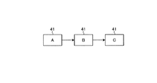
ところで、LCD41に表示させる情報は、映像データやカプセル型内視鏡の位置情報に限らず、たとえば上述した患者ID、患者名、年齢などを示す被検者の識別情報や検査ID、検査時間などの検査に関する情報やカプセルID、カプセルの電池残量などのカプセル型内視鏡に関する情報や受信装置ID、電力供給部17の電池残量、無線信号の受信状態、受信装置の発する警告などの受信装置に関する情報を表示させることも可能である。これらの情報は、映像信号に重畳させて受信装置2から小型表示装置たるビュワー4に送信しても良いし、または小型表示装置たるビュワー4内、たとえば制御部49の図示しない内部メモリに登録させておき、これらの情報を指定することが可能な操作部50の表示切替指示に基づいて、該当する情報を少なくとも1つLCD41に表示させるように設定することも可能である。たとえば、図6に示すように、Aの時のLCD41の画面には、映像データを表示し、操作部50の表示切替指示によりBの時のLCD41の画面には、検査ID、検査時間などの検査に関する情報を表示し、次の操作部50の表示切替指示によりCの時のLCD41の画面には、被検体内地図やカプセル型内視鏡3の位置を表示させることが可能となる。
By the way, the information to be displayed on the
このように、この実施の形態では、小型表示装置たるビュワー4は、カプセル型内視鏡3によって撮像された体腔内画像などを表示するためのものであり、通信ケーブル接続検知部48による接続検知に基づき、制御部49が切替スイッチ44を制御して、LCD41の表示切り替えを行い、通信ケーブル5を介して受信装置2から被検体内情報などの検査に必要な情報を取り込んでLCD41に表示させることができるので、受信装置に表示手段が必要なくなるとともに、回路構成が簡単になり、これによって受信装置の小型・軽量化を図るとともに、低消費電力化を図ることができる。
As described above, in this embodiment, the viewer 4 as a small display device is for displaying an in-vivo image taken by the capsule endoscope 3, and the connection detection by the communication cable
また、この実施の形態では、受信装置2との接続を検知して、小型表示装置たるビュワー4内の切り替え制御によって被検体内情報をLCD41に表示させることができるので、受信装置2に小型表示装置たるビュワー4を接続させるという簡単な操作だけで、迅速、かつリアルタイムにカプセル型内視鏡3から取得した映像データなどの検査に必要な情報を小型表示装置たるビュワー4のLCD41に表示させることができる。
Further, in this embodiment, since the connection with the receiving device 2 is detected and the in-subject information can be displayed on the
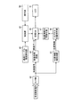
(実施の形態2)
図7は、図1に示した小型表示装置たるビュワーの実施の形態2にかかる構成を示すブロック図である。なお、図4と同様な構成部分に関しては、説明の都合上、同一符号を付記するものとする。
(Embodiment 2)
FIG. 7 is a block diagram showing a configuration according to the second embodiment of the viewer which is the small display device shown in FIG. In addition, about the component similar to FIG. 4, the same code | symbol shall be attached for convenience of description.
この実施の形態では、小型表示装置たるビュワー4が本来携帯している無線機能と、実施の形態1で示した有線による受信機能との切り替えを可能とするものである。すなわち、この実施の形態では、図4に示した構成の他に、受信用アンテナ57からの無線信号を受信する受信回路58と、受信回路58で復調された映像信号を画像処理して映像データを切替スイッチ44に出力する画像処理回路59とを備える。
In this embodiment, it is possible to switch between the wireless function originally carried by the viewer 4 which is a small display device and the wired reception function shown in the first embodiment. That is, in this embodiment, in addition to the configuration shown in FIG. 4, a receiving
小型表示装置たるビュワー4では、通信ケーブル5によって受信装置2と接続される前の状態では、たとえばカプセル型内視鏡3から受信回路58によって直接、映像信号を受信しており、制御部49は、切替スイッチ44の切り替え制御によって、この受信回路58で復調され、かつ画像処理回路59で処理された映像データをLCD41に表示させている。
In the viewer 4 which is a small display device, in a state before being connected to the receiving device 2 by the
ここで、通信ケーブル5が受信装置2に接続され、この接続を通信ケーブル接続検知部48が検知すると、制御部49は、切替スイッチ44を有線による受信機能(画像処理回路43側)に切り替え制御して、受信装置2からの映像データをLCD41に表示させる。この際には、受信回路58で受信した画像データを、たとえば図示しない内部メモリなどに記憶させておいて、その後に操作部50の切り替え指示に基づいて、制御部49が切替スイッチ44を制御して、LCD41に表示させてもよいし、またはLCD41に表示させることなく破棄してもよい。なお、操作部50は、無線による映像データの表示、有線による映像データの表示、位置情報の表示などの表示指示を行うことができる。
Here, when the
このように、この実施の形態では、有線によって取り込んだ映像データの表示と、無線によって取り込んだ映像データの表示とを、通信ケーブル接続検知部48による接続検知に基づき、制御部49が切替スイッチ44を制御して、上記表示切り替えを行い、通信ケーブル5を介して受信装置2から被検体内情報などの検査に必要な情報を取り込んでLCD41に表示させることができるので、実施の形態1と同様、受信装置に表示手段が必要なくなるとともに、回路構成が簡単になり、これによって受信装置の小型・軽量化を図るとともに、低消費電力化を図ることができる。
As described above, in this embodiment, the
また、この実施の形態では、実施の形態1と同様に、小型表示装置たるビュワー4と受信装置2との接続を検知して、小型表示装置たるビュワー4が本来携帯している無線機能と、有線による受信機能との切り替え制御を行なって、受信装置2から検査に必要な情報を取り込んでLCD41に表示させることができるので、迅速、かつリアルタイムにカプセル型内視鏡3から取得した映像データなどの検査に必要な情報を小型表示装置たるビュワー4のLCD41に表示させることができる。
In this embodiment, as in the first embodiment, the connection between the viewer 4 that is a small display device and the receiving device 2 is detected, and the wireless function that the viewer 4 that is the small display device originally carries; Since switching control with a wired reception function can be performed and information necessary for the inspection can be taken from the receiving device 2 and displayed on the
1 被検体
2 受信装置
2a 受信ジャケット
2b 外部装置
3 カプセル型内視鏡
4 ビュワー
5 通信ケーブル
11 チューナー
12 2値化回路
13 重畳部
14 インターフェース部
15 サンプルホールド回路
16 A/D変換部
17 電力供給部
18,56 電源スイッチ
21 コネクタ
22 突起
41 表示部
42 S/P変換部
43,59 画像処理回路
44 切替スイッチ
45 位置情報検出回路
46 カプセル位置解析部
47 画像化部
48 通信ケーブル接続検知部
49 制御部
50 操作部
51,CON 接続部
52 接点ピン
53 スプリング
54,55 電路
57,A1〜An 受信用アンテナ
58 受信回路
CON1〜CONn コネクタ
DESCRIPTION OF
Claims (12)
前記受信装置と前記小型表示装置を通信可能に接続する通信手段を、
備え、前記受信装置は、少なくとも前記被検体内情報を前記通信手段を介して、前記小型表示装置に出力し、
前記小型表示装置は、
前記通信手段による前記受信装置との接続を検知する検知手段と、
前記検知手段の検知結果に基づいて、前記表示部の表示を、前記通信手段を介して取り込んだ前記被検体内情報の表示に切り替える切替制御手段と、
を備えることを特徴とする被検体内情報取得システム。 Inside a subject having a receiving device for receiving in-subject information wirelessly transmitted from an in-subject introducing device to be introduced into the subject, and a small display device for capturing the in-subject information and displaying it on a display unit In the information acquisition system,
A communication means for connecting the receiving device and the small display device in a communicable manner;
The receiving device outputs at least the in-subject information to the small display device via the communication means,
The small display device includes:
Detecting means for detecting connection with the receiving device by the communication means;
Based on the detection result of the detection means, switching control means for switching the display of the display section to display of the in-subject information captured via the communication means;
An in-subject information acquisition system comprising:
前記受信装置と前記小型表示装置を通信可能に接続する通信手段を、
備え、前記受信装置は、少なくとも前記被検体内情報を前記通信手段を介して、前記小型表示装置に出力し、
前記小型表示装置は、
前記通信手段による前記受信装置との接続を検知する検知手段と、
前記被検体内導入装置から無線送信される被検体内情報を受信する無線手段と、
前記検知手段による検知結果に基づいて、前記無線手段または前記通信手段による受信動作を切り替え制御する切替制御手段と、
を備えることを特徴とする被検体内情報取得システム。 Inside a subject having a receiving device for receiving in-subject information wirelessly transmitted from an in-subject introducing device to be introduced into the subject, and a small display device for capturing the in-subject information and displaying it on a display unit In the information acquisition system,
A communication means for connecting the receiving device and the small display device in a communicable manner;
The receiving device outputs at least the in-subject information to the small display device via the communication means,
The small display device includes:
Detecting means for detecting connection with the receiving device by the communication means;
Wireless means for receiving in-subject information wirelessly transmitted from the in-subject introduction apparatus;
A switching control means for switching and controlling a reception operation by the wireless means or the communication means based on a detection result by the detecting means;
An in-subject information acquisition system comprising:
前記受信装置は、
前記被検体内導入装置からの被検体内情報を受信する受信アンテナと、
前記受信アンテナの受信強度を検出する受信強度検出手段と、
前記受信強度検出手段で検出された受信強度の情報を、前記被検体内情報に重畳する重畳手段と、
をさらに備え、
前記小型表示装置は、
前記受信強度の情報に基づいて、前記被検体内導入装置の位置を解析する解析手段と、
前記表示部に表示させる情報を指示する指示手段と、
をさらに備え、
前記切替制御手段は、前記指示手段の指示に応じて、前記表示部に表示させる情報を切り替えることを特徴とする請求項1または2に記載の被検体内情報取得システム。 The in-subject information transmitted by the in-subject introduction apparatus includes at least a video signal obtained by imaging the inside of the subject,
The receiving device is:
A receiving antenna for receiving in-subject information from the in-subject introduction device;
Reception intensity detection means for detecting the reception intensity of the reception antenna;
Superimposing means for superimposing the information on the received intensity detected by the received intensity detecting means on the in-subject information;
Further comprising
The small display device includes:
Analysis means for analyzing the position of the intra-subject introduction device based on the information of the received intensity;
Instruction means for instructing information to be displayed on the display unit;
Further comprising
The in-subject information acquisition system according to claim 1, wherein the switching control unit switches information to be displayed on the display unit in accordance with an instruction from the instruction unit.
前記小型表示装置は、
前記表示部に表示させる情報を指示する指示手段を、
さらに備え、
前記切替制御手段は、前記指示手段の指示に応じて、前記表示部に表示させる情報を切り替えることを特徴とする請求項1または2に記載の被検体内情報取得システム。 The in-subject information transmitted by the in-subject introduction apparatus includes at least a video signal obtained by imaging the inside of the subject and position information of the in-subject introduction apparatus,
The small display device includes:
Instructing means for instructing information to be displayed on the display unit,
In addition,
The in-subject information acquisition system according to claim 1, wherein the switching control unit switches information to be displayed on the display unit in accordance with an instruction from the instruction unit.
前記表示部は、前記切替制御手段の表示切り替えによって、これら情報のうち、少なくとも1つの情報を表示することを特徴とする請求項3または4に記載の被検体内情報取得システム。 Information to be displayed on the display unit includes the video signal, information about the in-subject introduction apparatus, information about the receiving apparatus, position information of the in-subject introduction apparatus, information about examination of the subject , and the subject Including identification information
The in-vivo information acquiring system according to claim 3 or 4, wherein the display unit displays at least one of these pieces of information by display switching of the switching control means.
前記受信装置は、前記表示部に表示させる情報を前記通信ケーブルを介して前記小型表示装置に送信することを特徴とする請求項5に記載の被検体内情報取得システム。 The in-vivo information acquiring system according to claim 5, wherein the receiving device transmits information to be displayed on the display unit to the small display device via the communication cable.
前記切替制御手段は、前記切替スイッチの切り替え制御を行うことを特徴とする請求項5に記載の被検体内情報取得システム。 The in-vivo information acquiring system according to claim 5, wherein the switching control unit performs switching control of the selector switch.
Priority Applications (6)
| Application Number | Priority Date | Filing Date | Title |
|---|---|---|---|
| JP2005111131A JP4015666B2 (en) | 2005-04-07 | 2005-04-07 | In-subject information acquisition system |
| CN2006800090228A CN101146476B (en) | 2005-04-07 | 2006-04-06 | System for acquiring information on inside of subject |
| EP06731287A EP1867280A4 (en) | 2005-04-07 | 2006-04-06 | System for acquiring information on inside of subject |
| PCT/JP2006/307339 WO2006109676A1 (en) | 2005-04-07 | 2006-04-06 | System for acquiring information on inside of subject |
| US11/658,826 US8348832B2 (en) | 2005-04-07 | 2006-04-06 | Intra-subject information acquiring system |
| KR1020077022771A KR100924614B1 (en) | 2005-04-07 | 2006-04-06 | System for acquiring information on inside of subject |
Applications Claiming Priority (1)
| Application Number | Priority Date | Filing Date | Title |
|---|---|---|---|
| JP2005111131A JP4015666B2 (en) | 2005-04-07 | 2005-04-07 | In-subject information acquisition system |
Publications (3)
| Publication Number | Publication Date |
|---|---|
| JP2006288543A JP2006288543A (en) | 2006-10-26 |
| JP2006288543A5 JP2006288543A5 (en) | 2007-04-12 |
| JP4015666B2 true JP4015666B2 (en) | 2007-11-28 |
Family
ID=37086951
Family Applications (1)
| Application Number | Title | Priority Date | Filing Date |
|---|---|---|---|
| JP2005111131A Expired - Fee Related JP4015666B2 (en) | 2005-04-07 | 2005-04-07 | In-subject information acquisition system |
Country Status (6)
| Country | Link |
|---|---|
| US (1) | US8348832B2 (en) |
| EP (1) | EP1867280A4 (en) |
| JP (1) | JP4015666B2 (en) |
| KR (1) | KR100924614B1 (en) |
| CN (1) | CN101146476B (en) |
| WO (1) | WO2006109676A1 (en) |
Families Citing this family (12)
| Publication number | Priority date | Publication date | Assignee | Title |
|---|---|---|---|---|
| JP4602822B2 (en) * | 2005-04-07 | 2010-12-22 | オリンパスメディカルシステムズ株式会社 | In-subject information acquisition system |
| JP4734068B2 (en) * | 2005-09-09 | 2011-07-27 | オリンパスメディカルシステムズ株式会社 | Body cavity image observation device |
| US8038608B2 (en) | 2005-09-09 | 2011-10-18 | Olympus Corporation | Body-cavity image observation apparatus |
| JP5403880B2 (en) * | 2007-06-27 | 2014-01-29 | オリンパスメディカルシステムズ株式会社 | Image information display processing device |
| JP2009112644A (en) * | 2007-11-08 | 2009-05-28 | Olympus Medical Systems Corp | Image processor |
| JP5259174B2 (en) * | 2007-12-25 | 2013-08-07 | オリンパスメディカルシステムズ株式会社 | Transmission / reception system |
| US8406490B2 (en) | 2008-04-30 | 2013-03-26 | Given Imaging Ltd. | System and methods for determination of procedure termination |
| AU2010235197B2 (en) | 2009-03-31 | 2014-10-16 | Covidien Lp | Method of determining body exit of an ingested capsule |
| JP5032646B2 (en) | 2010-11-24 | 2012-09-26 | 株式会社東芝 | IMAGING DEVICE, IMAGING DEVICE OPERATING METHOD, AND ENDOSCOPE DEVICE |
| JP5690447B2 (en) * | 2012-10-15 | 2015-03-25 | オリンパスメディカルシステムズ株式会社 | Information management apparatus and capsule endoscope inspection system |
| JP5961126B2 (en) | 2013-03-04 | 2016-08-02 | 日本光電工業株式会社 | Biological information monitor system |
| WO2020202531A1 (en) * | 2019-04-04 | 2020-10-08 | オリンパス株式会社 | Receiver system |
Family Cites Families (13)
| Publication number | Priority date | Publication date | Assignee | Title |
|---|---|---|---|---|
| US6043839A (en) * | 1997-10-06 | 2000-03-28 | Adair; Edwin L. | Reduced area imaging devices |
| US6402689B1 (en) * | 1998-09-30 | 2002-06-11 | Sicel Technologies, Inc. | Methods, systems, and associated implantable devices for dynamic monitoring of physiological and biological properties of tumors |
| DE10059662B4 (en) * | 1999-12-03 | 2009-04-02 | Hoya Corp. | Electronic endoscope system |
| IL143260A (en) | 2001-05-20 | 2006-09-05 | Given Imaging Ltd | Array system and method for locating an in vivo signal source |
| JP2003125457A (en) * | 2001-10-16 | 2003-04-25 | Toshiba Corp | Radio communication terminal apparatus and method for radio communication |
| JP3756797B2 (en) * | 2001-10-16 | 2006-03-15 | オリンパス株式会社 | Capsule type medical equipment |
| JP3974769B2 (en) * | 2001-11-06 | 2007-09-12 | オリンパス株式会社 | Capsule medical device |
| JP2004167163A (en) | 2002-11-22 | 2004-06-17 | Olympus Corp | Capsule type medical care system |
| KR100743332B1 (en) * | 2003-04-25 | 2007-07-26 | 올림푸스 가부시키가이샤 | Capsule endoscope and capsule endoscope system |
| JP3810381B2 (en) * | 2003-04-25 | 2006-08-16 | オリンパス株式会社 | Image display device, image display method, and image display program |
| JP4402655B2 (en) * | 2003-05-14 | 2010-01-20 | オリンパス株式会社 | Capsule medical device |
| JP4526245B2 (en) | 2003-07-04 | 2010-08-18 | オリンパス株式会社 | Video signal processing device |
| JP4938231B2 (en) * | 2004-10-25 | 2012-05-23 | ルネサスエレクトロニクス株式会社 | Flatness measuring instrument |
-
2005
- 2005-04-07 JP JP2005111131A patent/JP4015666B2/en not_active Expired - Fee Related
-
2006
- 2006-04-06 KR KR1020077022771A patent/KR100924614B1/en not_active IP Right Cessation
- 2006-04-06 EP EP06731287A patent/EP1867280A4/en not_active Withdrawn
- 2006-04-06 US US11/658,826 patent/US8348832B2/en active Active
- 2006-04-06 WO PCT/JP2006/307339 patent/WO2006109676A1/en active Application Filing
- 2006-04-06 CN CN2006800090228A patent/CN101146476B/en not_active Expired - Fee Related
Also Published As
| Publication number | Publication date |
|---|---|
| US20090076320A1 (en) | 2009-03-19 |
| EP1867280A4 (en) | 2010-11-17 |
| CN101146476A (en) | 2008-03-19 |
| CN101146476B (en) | 2010-05-19 |
| EP1867280A1 (en) | 2007-12-19 |
| JP2006288543A (en) | 2006-10-26 |
| KR20070110904A (en) | 2007-11-20 |
| US8348832B2 (en) | 2013-01-08 |
| KR100924614B1 (en) | 2009-11-02 |
| WO2006109676A1 (en) | 2006-10-19 |
Similar Documents
| Publication | Publication Date | Title |
|---|---|---|
| JP4015666B2 (en) | In-subject information acquisition system | |
| JP4847075B2 (en) | Receiver | |
| JP4823659B2 (en) | In vivo image display device | |
| US20070135684A1 (en) | In-vivo information acquiring apparatus | |
| WO2007026890A1 (en) | Portable simplified image display device and receiving system | |
| JP2007068895A (en) | Inspection method of disconnection | |
| EP1967124B1 (en) | In vivo image display apparatus and receiving system | |
| JP2007167555A5 (en) | ||
| WO2006038524A1 (en) | Receiving apparatus and receiving system | |
| JP4610974B2 (en) | Receiver | |
| JP4602822B2 (en) | In-subject information acquisition system | |
| JP4663279B2 (en) | Reception device, medical device, and identification information generation registration method | |
| JP4009612B2 (en) | Receiver | |
| JP4009610B2 (en) | Receiver | |
| JP2005218703A (en) | Receiving apparatus | |
| JP4445806B2 (en) | Receiver | |
| JP2006026299A (en) | Receiving device | |
| JP4547192B2 (en) | Antenna device | |
| JP2005312769A (en) | Receiver and medical apparatus | |
| JP2005218704A (en) | Receiving apparatus | |
| JP2005223427A (en) | Receiver | |
| WO2012073761A1 (en) | Transmitter-receiver device, antenna unit and system to be introduced into subject | |
| JP2006043109A (en) | Receiver and medical device |
Legal Events
| Date | Code | Title | Description |
|---|---|---|---|
| A521 | Request for written amendment filed |
Free format text: JAPANESE INTERMEDIATE CODE: A523 Effective date: 20070226 |
|
| A621 | Written request for application examination |
Free format text: JAPANESE INTERMEDIATE CODE: A621 Effective date: 20070226 |
|
| TRDD | Decision of grant or rejection written | ||
| A01 | Written decision to grant a patent or to grant a registration (utility model) |
Free format text: JAPANESE INTERMEDIATE CODE: A01 Effective date: 20070911 |
|
| A61 | First payment of annual fees (during grant procedure) |
Free format text: JAPANESE INTERMEDIATE CODE: A61 Effective date: 20070913 |
|
| FPAY | Renewal fee payment (event date is renewal date of database) |
Free format text: PAYMENT UNTIL: 20100921 Year of fee payment: 3 |
|
| FPAY | Renewal fee payment (event date is renewal date of database) |
Free format text: PAYMENT UNTIL: 20100921 Year of fee payment: 3 |
|
| FPAY | Renewal fee payment (event date is renewal date of database) |
Free format text: PAYMENT UNTIL: 20110921 Year of fee payment: 4 |
|
| FPAY | Renewal fee payment (event date is renewal date of database) |
Free format text: PAYMENT UNTIL: 20120921 Year of fee payment: 5 |
|
| FPAY | Renewal fee payment (event date is renewal date of database) |
Free format text: PAYMENT UNTIL: 20130921 Year of fee payment: 6 |
|
| S111 | Request for change of ownership or part of ownership |
Free format text: JAPANESE INTERMEDIATE CODE: R313111 |
|
| R350 | Written notification of registration of transfer |
Free format text: JAPANESE INTERMEDIATE CODE: R350 |
|
| S531 | Written request for registration of change of domicile |
Free format text: JAPANESE INTERMEDIATE CODE: R313531 |
|
| R350 | Written notification of registration of transfer |
Free format text: JAPANESE INTERMEDIATE CODE: R350 |
|
| LAPS | Cancellation because of no payment of annual fees |