JP2004024340A - Endoscope equipment - Google Patents
Endoscope equipment Download PDFInfo
- Publication number
- JP2004024340A JP2004024340A JP2002181909A JP2002181909A JP2004024340A JP 2004024340 A JP2004024340 A JP 2004024340A JP 2002181909 A JP2002181909 A JP 2002181909A JP 2002181909 A JP2002181909 A JP 2002181909A JP 2004024340 A JP2004024340 A JP 2004024340A
- Authority
- JP
- Japan
- Prior art keywords
- image
- endoscope
- personal computer
- monitor
- still image
- Prior art date
- Legal status (The legal status is an assumption and is not a legal conclusion. Google has not performed a legal analysis and makes no representation as to the accuracy of the status listed.)
- Pending
Links
Images


Landscapes
- Endoscopes (AREA)
- Closed-Circuit Television Systems (AREA)
- Instruments For Viewing The Inside Of Hollow Bodies (AREA)
Abstract
Description
【0001】
【発明の属する技術分野】
本発明は機械設備の内部等に挿入して内視鏡検査を行う挿入部をケース部内に収納した内視鏡装置に関する。
【0002】
【従来の技術】
近年、医療用分野に限らず工業用分野においても内視鏡が広く採用されるようになった。
従来の内視鏡装置として、図10に示すような内視鏡装置31がある。この内視鏡装置31は、内視鏡装置本体(以下、単に本体部と略記)32と、この本体部32から延出される可撓性の挿入部6と、本体部32に接続され、内視鏡画像を表示する第1モニタ34及び第2モニタ35とから構成される。
【0003】
挿入部6には照明光を伝送するライトガイド11が挿通され、その後端は本体部32に内蔵された光源12に接続され、この光源12に内蔵されたランプにより発光された照明光がライトガイド11の後端面に供給され、挿入部3の先端面に伝送される。
【0004】
そして、ライトガイド11の先端面から前方に拡開して出射され、プラント内部等の検査対象となる被写体を照明する。照明された被写体は挿入部3の先端部の観察窓(撮像窓)に設けた対物レンズ13により、光学像を結ぶ。この結像位置には電荷結合素子(CCD)等の固体撮像素子(以下では撮像素子と略記)14が配置されており、撮像素子14により光電変換される。
【0005】
この撮像素子14は挿入部3内を挿通された信号線15を介して、本体部32に内蔵されたカメラコントロールユニット(以下、CCUと略記)16に接続され、このCCU16は撮像素子14に駆動信号を印加して、光電変換された撮像信号(画像信号)を読み出し、その読み出された撮像信号に対して映像信号(ビデオ信号)を生成する信号処理を行う。
【0006】
このCCU16から出力されるビデオ信号はA/D変換器17に入力され、A/D変換されてデジタルのビデオ信号に変換されて、バスライン18上に入力画像データとして送り出される。
【0007】
このバスライン18には制御を行うCPU19、このCPU19による制御機能のプログラムを格納したROM20、CPU19によるワーク領域等に使用されるRAM21、アナログ信号に変換するD/A変換器22、画像データを記録するメモリカード23、入出力インタフェース(図10中ではIO/IFと略記)24が接続されている。
【0008】
CPU19は、第1の機能として、バスライン18上の入力画像データを読み込んではそのままバスライン18上に出力画像データとして送り出す。
D/A変換器22は、バスライン18上の出力画像データをD/A変換してアナログのビデオ信号を第1モニタ34及び第2モニタ35に出力し、これらのモニタ34、35はこのD/A変換器22から出力されたビデオ信号が入力されることにより、その表示面に撮像素子14で撮像した画像を内視鏡画像として表示する。
【0009】
また、この本体部32には操作ボタン9が設けてあり、操作者が操作ボタン9を操作すると、その操作信号は入出力インタフェース(図10ではIO/IFと略記)24からバスライン18を介してCPU19に読み込まれる。
【0010】
例えば、操作ボタン9における画像記録の操作が行われると、CPU19は第2の機能として、入力画像データをメモリカード23の所定の領域に書き込む。メモリカード23には、画像記録の操作によってその時、観察している画像が次々と記録される。メモリーカード23は本体部32から着脱可能であり、外して保管したり、PC(パソコン)などに接続して画像データを読み出すことができる。
【0011】
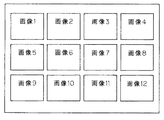
画像再生の操作が行われると、CPU19は第3の機能として、メモリーカード23に記録されている画像データを読み出し、再生する。CPU19はまず、メモリーカード23に記録されている複数の画像データを読み出し、その各々を縮小して全体で1枚の画像(サムネイル画像)を作成する。
CPU19はこれを出力画像データとして送り出す。第1モニタ34及び第2モニタ35には図11に示すようなサムネイル画像(画像1〜画像12)が表示される。
【0012】
続いて、操作ボタン9により画像の選択操作が行われると、CPU19は選択された1枚の画像の画像データをそのまま送り出す。第1モニタ34及び第2モニタ35にはその選択された画像が表示される。
【0013】
上記のようなCPU19の各機能は、あらかじめROM20に記録されているプログラムに従って行われる。またこれらの機能を実行するためのワーク領域としてRAM21が使用される。
また、本体部32には電源26が設けてあり、本体部32内の各部に電力を供給する部分で、バッテリなどから構成されている。
なお、第2モニタ35は以下に説明するように比較的長いケーブル36によりD/A変換器22と接続される。
【0014】
内視鏡は機械設備の内部を検査することがその主な用途である。機械設備としては飛行機のエンジン、化学プラント、発電所のボイラなどがある。これらを検査する場合、検査員は狭い場所、高所など比較的作業のしにくい場所で作業しなければならないことが多い。
【0015】
一方、検査においては検査結果を正確に判断することが重要である。そのため内視鏡検査では、最低限、直接内視鏡を操作する操作員のみが前記のような作業のしにくい場所に居て内視鏡を操作し、検査の状況を判断するのはそこから少し離れた比較的良好な場所において別の人員によって行う場合も多い。
【0016】
このようなやりかたで検査を行うために、内視鏡装置31自体を操作するために操作員が画像を見るために設けている第1モニタ34の他に、少し離れた場所において判断のために別の検査員が見る第2モニタ35を設置している。第2モニタ35は比較的長いケーブル36を用いて本体部32内のD/A変換器22に接続される。D/A変換器22から出力されたビデオ信号はこのケーブル36を介して第2モニタ35にも供給される。
【0017】
【発明が解決しようとする課題】
第2モニタ35に画像を映し出すために、長いケーブル36を設置しなければならない。高所など、ケーブル36の設置作業が非常にやりにくいことがある。検査現場はいろいろな作業員が絶えず行き来することが多く、ケーブル36があると足をひっかけるなど、弊害が多い。
検査現場を移動するたびにケーブル36の設置状態を変えなければならず、非常に面倒である。
【0018】
種々のデメリットをがまんしてケーブル36を設置しても、検査員が見ている第2モニタ35では画像を表示することだけしかできない。検査員が本内視鏡装置31にすでに記録されている画像を読み出すなど、内視鏡を遠隔操作することはできない。これらは検査員から内視鏡の作業員にいちいち要求し、操作してもらわなければならない。
【0019】
なお、特願2001−335036に示す遠隔検査システムでは、内視鏡にPC(「検査PC」と称す)を接続し、一方、第2の装置としてPC(「センターPC」と称す)を設置し、検査PCとセンターPCをLANまたはインターネットで結んでいる。
【0020】
この検査システムによれば、離れた場所にある別のPC(センターPC)において内視鏡画像を見ることはもちろんのこと、内視鏡を操作して画像を記録する、記録されている画像を読み出すなどの遠隔操作ができる。
しかし、この場合には、2つのPCが必要になってしまう。
【0021】
(発明の目的)
本発明は上述した点に鑑みてなされたもので、本体部から離れた場所でモニタ画像を検査する場合にも適用が可能な内視鏡装置を提供することを目的とする。
【課題を解決するための手段】
先端部に撮像素子を有する挿入部と;
前記撮像素子からの出力信号に対する信号処理を行う信号処理装置と、
前記信号処理装置により信号処理された映像信号を記録する画像記録部と、
を有する本体部と;
前記挿入部と本体部とを収納可能とするケース部とからなる内視鏡装置において、
前記映像信号を遠隔地に送信するためのネットワークインタフェースを設けたことにより、ネットワークを介して画像情報を送信できるようにして、本体部から離れた場所でもモニタ画像を見て検査できる。
【0022】
【発明の実施の形態】
以下、図面を参照して本発明の実施の形態を説明する。
(第1の実施の形態)
図1ないし図4は本発明の第1の実施の形態に係り、図1は第1の実施の形態を備えた工業用内視鏡システムの全体構成を示し、図2は内視鏡装置の構成を示し、図3はリモートパソコンの内部構成を示し、図4は変形例における内視鏡装置の主要部の構成を示す。
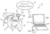
図1に示すように工業用内視鏡システム1は工業用内視鏡装置(以下、単に内視鏡装置と略記)2と、この内視鏡装置2と離れた場所に設置され、この内視鏡装置2とLAN或いはインタネットによるネットワーク(通信回線)4を介して接続される情報通信端末としての、例えばノート型のパーソナルコンピュータ(以下、パソコンと略記)で形成されるリモートパソコン3とから構成される。
【0023】
内視鏡装置2は、例えば箱形状のケース5でその外装が形成され、内視鏡検査を行う場合に機械設備の内部に挿入される挿入部6はこのケース5の内部から引き出され、また使用後は挿入部6はケース5の内部に収納される。
また、このケース5の内部には信号処理手段や画像記録手段を備えた、例えばドラム形状の本体部7が内蔵されている。
【0024】
そして、ケース5の前面に設けたハンドル5aを回転することにより、ケース5の例えば上面に設けた収納口5bから外部に引き出された細長の挿入部6を本体部7の円筒状外周面部分に巻き付けてケース5内部に収納できるようにしている。
【0025】
このケース5の上面には伸縮自在のポールを介して液晶ディスプレイで形成したモニタ8が取り付けてある。
このケースの上面には操作ボタン9が設けてあり、画像記録や画像再生等の操作を行うことができる。
【0026】
また、このケース5の上面には回動により開閉自在の蓋10が取り付けてあり、内視鏡検査を行わない場合には蓋10を閉じてモニタ8や操作ボタン9を覆うことができるようにしている。
【0027】
一方、通信機能と画像表示機能とを備えた情報通信端末としてのリモートパソコン3は、データ入力等を行うキーボード部27、ポインティングデバイスとして各種の指示操作を行うためののマウス28、そして内視鏡画像の表示を行うLCDモニタ部29(単にモニタ部ともいう)を有する。
【0028】
図2は内視鏡装置2の全体構成を示す。
図2に示す内視鏡装置2は図10に示す内視鏡装置31において、基本的には本体部32の内部にネットワークインタフェース(図2ではネットワーク/IFと略記)37を設けた構成にして本体部7を形成しており、このネットワークインタフェース37はその外周のケース5に設けたコネクタ38に接続されている。
【0029】
そして、このコネクタ38にケーブル39を介してLAN或いはインタネットのネットワーク4に接続できるようにしている。
より具体的に内視鏡装置2の構成を説明すると、可撓性を有する細長の挿入部6内には照明光を伝送するライトガイド11が挿通され、本体部7に内蔵された光源12で発生した照明光を伝送し、先端面から出射する。
【0030】
また、挿入部6の先端部には対物レンズ13が配置され、その結像位置にCCDなどからなる撮像素子14が配置され、信号線15を介して本体部7に内蔵したCCU16と接続されている。
【0031】
信号線15により撮像素子14と電気的に接続され、信号処理手段を構成するCCU16内部の駆動回路から駆動信号を撮像素子14に印加することにより、撮像素子14で光電変換された撮像信号が出力される。
この撮像信号はCCU16内部の信号処理回路に入力され、ビデオ信号に変換された後、このビデオ信号はデジタルのビデオ信号に変換するD/A変換器17に入力される。
【0032】
このA/D変換器17は本体部7内部のバスライン18に接続されている。バスライン18にはCPU19、ROM20、RAM21、表示用RAM30、メモリカード23、入出力インタフェース24、ネットワークインタフェース37とが接続されている。入出力インタフェース24には、操作ボタン9が接続されている。
また、表示用RAM30には液晶ディスプレイなどで形成されたモニタ8が接続されている。そして、CPU19は出力画像データをこの表示用RAM30に書き込む。この表示用RAM30に書き込まれた画像データーは常にモニタ8に送り出され、表示される。
【0033】
また、本体部7の電源26にはバッテリが収納されており、本体部7の光源12、CCU16等に駆動電力を供給する。また、ACケーブル40を用いて商用電源で駆動することもでき、ACケーブル40を用いた場合には電源26の内部のバッテリを充電もする。
【0034】
図3はリモートパソコン3の内部構成を示す。
この構成は本実施の形態に特有な構成ではなく、近年広く市販されている一般的なノート型のパソコンの構成である。
【0035】
リモートパソコン3は、全体の制御を行うCPU41がインターナルバス42に接続されている。このインターナルバス42には、CPU41の作業エリア等に利用されるRAM43、USBコネクタ受け44に接続されたUSBインターフェース45、マウス28のコネクタが(コネクタ受けを介して)接続されるマウスインターフェース46が接続されている。
【0036】
また、このインターナルバス42には、キーボード部27、プログラムが格納されたハードディスク(図3ではHDと略記)ドライブ47、フロッピーディスク(フロッピーは登録商標)等のフレキシブルディスク(FDと略記)ドライブ48、CD−ROMドライブ49がそれぞれのインターフェース22a、47a、48a、49aを介して接続されている。また、インターナルバス42には、ネットワークインタフェース51も接続され、このネットワークインタフェース51はケーブル52を介してLAN或いはインタネット等のネットワーク4と接続される。
また、LCDモニタ部29は表示制御を行う表示制御回路50を介してRAM43及びインターナルバス42に接続されている。
CPU41はハードディスクドライブ47に内蔵されたプログラムを最初に読み出してRAM43内の所定の領域に書き出し、以後はそのプログラムによって動作する。
【0037】
本実施の形態では、リモートパソコン3には内視鏡装置2からネットワーク4を介して送信される静止画像のデータを受け、モニタ部29に静止画像を表示する動作を行うプログラムが格納されている。
具体的には、CPU41はネットワークインタフェース51を介して送られてくる画像データをRAM43内の所定の領域に格納する。表示制御回路50はRAM43内に格納された表示用データを繰り返し読み出し、モニタ部29に表示させるための信号に常時変換する。そして、その信号はモニタ部29に送られ、表示されるようになっている。
【0038】
本実施の形態では、ネットワークインタフェース37を設けた内視鏡装置2により、画像情報をネットワーク4側に送信できるようにし、またこのネットワーク4にネットワークインタフェースを備えた情報通信端末としてのリモートパソコン3を第2のモニタとして使用することにより、内視鏡装置2とリモートパソコン3とを直接ケーブルで接続しなくても、内視鏡装置2側で記録した静止画像を送信することによりリモートパソコン3側でその静止画像を観察できるようにしていることが特徴となっている。
【0039】
次に本実施の形態の作用を以下に説明する。具体的には、操作員が内視鏡装置2を操作して機械設備の内部を内視鏡検査し、この場合操作員から離れた場所で検査員がリモートパソコン3で観察する場合で説明する。
図1に示すように、本体部7を内蔵したケース5のコネクタ38をケーブル39を介してネットワーク4に接続し、またリモートパソコン3もケーブル52を介してネットワーク4に接続する。
【0040】
そして、電源スイッチをONにして、それぞれを動作状態に設定し、両者をネットワーク4で通信可能な状態に設定する。操作員は機械設備の内部に挿入部6を挿入して内視鏡検査を行う。この場合、挿入部6の先端部に内蔵した撮像素子14により撮像された画像がモニタ8に表示される。
そして、画像を記録しようとした場合には、操作員が操作ボタン9における画像記録の指示ボタンを操作すると、その操作信号は入出力インタフェース24及びバスライン18を介してCPU19に読み込まれる。
【0041】
この画像記録の指示操作が行われると、CPU19はA/D変換器17を介して入力される画像データを静止画像データとしてメモリーカード23の所定の領域に書き込む。
それとともにCPU19は、今メモリーカード23に書き込んだ静止画像データをネットワークインタフェース37を介してネットワーク4に送出する。
【0042】
一方、内視鏡装置2から離れた場所に設置された第2の機器としてのリモートパソコン3にはネットワークインタフェース51が内蔵されており、ケーブル52を介してネットワーク4に接続されている。
本内視鏡装置2とリモートパソコン3上で互いのアドレスを認識しており、データをやりとりすることができる。
【0043】
内視鏡装置2側のCPU19がネットワーク4に送出した静止画像データはリモートパソコン3によって受信される。
画像記録の操作によって、そのとき観察している画像が次々とメモリーカード23に記録されることは図10の従来例で説明したのと同様である。メモリーカード23に新しい静止画像が記憶されるたびに、それがネットワーク4を介してリモートパソコン3側に伝送される。
【0044】
第2の機器としてのリモートパソコン3では、内部のCPU41はネットワーク4を介して受け取った静止画像データを内部のRAM43に保存しながら、モニタ部29の表示画面に自動的に表示する制御動作を行う。すなわち、新しい静止画像が送られてくると、リモートパソコン3ではそれまで表示していた画像に代えてこの新しい画像をモニタ部29の表示画面に表示する。
また、リモートパソコン3では内部のCPU41はRAM43に保存された静止画像データを内部のハードディスクドライブ47に自動的に記録するように制御する。
【0045】
検査員はリモートパソコン3のモニタ画面を見ている。そして、内視鏡装置2から送られてくる最新の静止画像を見ながら、検査員は判断を下すことができる。
検査員はリモートパソコン3を操作して、ハードディスクドライブ47に記録されている古い画像をモニタ画面に表示させ、再検討することもできる。
【0046】
本実施の形態によれば、内視鏡装置2の設置場所から離れた場所に第2の機器としてのリモートパソコン3を設置し、リモートパソコン3に画像を表示させて検査を行うことができる。
【0047】
また本実施の形態ではLAN或いはインターネットを用いているので内視鏡装置2と第2の機器としてのリモートパソコン3間の距離に制約がない。
また、リモートパソコン3側においては送られてくる静止画像を見るだけではなく、送られた画像の記録や記録された画像の読み出しなどの操作もできる。従って、より詳しい検査もし易い。
【0048】
(変形例)
図4は変形例における内視鏡装置2Bの主要部を示す。この内視鏡装置2Bは、図2の内視鏡装置2において、ネットワークインタフェース37の代わりにワイヤレスネットワークインタフェース(或いはワイヤレスLANインタフェース)55が用いられている。このワイヤレスネットワークインタフェース55にはネットワークインタフェースの他に無線送受信回路を備え、無線送受信回路によりネットワーク4と無線で接続される。
【0049】
なお、このワイヤレスネットワークインタフェース55の外装部分はケース5の上面から少し突出し、この突出する部分の内側には送受信するアンテナが内蔵されている。そして、使用しない場合には蓋10を閉じることにより、雨水等から保護することができるようにしている。
なお、リモートパソコン3側もワイヤレスネットワークカードを用いることにより、無線でネットワーク4と接続される。
【0050】
本変形例は第1の実施の形態の効果の他に、ワイヤレスネットワークインタフェース55にしているので内視鏡装置2Bをケーブルによりネットワーク4に接続することが不要となり、ケーブル接続作業等が不要となり、操作性を向上できる。
【0051】
また、リモートパソコン側もワイヤレスネットワークカードを用いることにより、無線でネットワーク4を介して内視鏡装置2Bと通信することができ、ケーブル接続作業が不要となり、操作性を向上できる。
【0052】
(第2の実施の形態)
次に本発明の第2の実施の形態を図5及び図6を参照して説明する。
検査対象物の状況が時間の経過とともに変化する場合などは、内視鏡装置によってそれを継続的に観察したいことがある。パイプに加わる温度が外力が変化したとき、パイプに異常が生じないかを内視鏡装置によって確認する場合などである。
【0053】
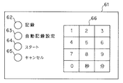
このような継続的観察をリモートパソコン3を用いて行う場合、図2等に示す本体部7側の操作ボタン9を操作員が何度も繰り返して操作するのでは不便であり、このような用途において、本実施の形態では図5に示すような操作ボタン61を用意した。
【0054】
図5に示すようにこの操作ボタン61には、(画像)記録ボタン62、自動記録設定ボタン63、スタートボタン64、キャンセルボタン65、及びテンキー66が設けてある。
そして、自動記録設定ボタン63を操作した場合にはテンキー66を操作して自動記録の時間間隔の設定を行えるようにしている。なお、このテンキー66には、通常の0〜9の数字キーの他に、秒、分のキーも用意されている。
【0055】
操作員は自動記録動作をさせるような場合には、操作員は自動記録設定ボタン63を押すと、CPU19の動作により、自動記録の間隔の設定を促すメッセージがモニタ8に表示される。
【0056】
操作員はテンキー66を用いて自動記録の間隔を設定する。続いてスタートボタン64を押すことにより自動記録動作が開始する。自動記録動作においては、設定した時間間隔ごとにそのときの内視鏡静止画像がメモリーカード23に記録されるとともに、ネットワーク4を介してリモートパソコン3に送信される。リモートパソコン3の動作は第1の実施形態と同様である。
【0057】
このようにして、自動記録動作では操作員が最初に一度操作をすれば、以後一定時間ごとに静止画像がメモリーカード23に記録されるとともに、リモートパソコン3に送られて表示される。検査員は刻々と変わる検査対象物の状況を、何の操作もすることなくリモートパソコン3にて観察できる。
キャンセルボタン65が押されると自動記録動作は中止される。
【0058】
図6はCPU19が自動記録動作を行うためのプログラムのフローチャートを示す。
自動記録設定ボタン63を操作して自動記録が開始すると、ステップS1の記録時間間隔設定の処理を行うことになる。つまり、CPU19は自動記録の間隔の設定を促すメッセージがモニタ8に表示されるように制御し、その表示に従って操作員はテンキー66を操作して記録時間間隔の設定入力を行う。すると、CPU19は記録時間間隔の設定データをRAM21に保存し、ステップS2のスタートボタン64が押されるのを待つ。
【0059】
そして、スタートボタン64が押されると、ステップS3に示すようにCPU19は記録時間間隔の設定データに従って、画像の記録及び記録した画像の送信の制御動作を行う。リモートパソコン3側では送信された画像を第1の実施の形態で説明したように、モニタ部29で表示すると共にハードディスクドライブ47に記録する。
【0060】
次のステップS4ではCPU19はキャンセルボタン65が押されたかの判断を行い、押された場合には、この自動記録の動作を終了し、キャンセルボタン65が押されていない場合には次のステップS5に進み、設定された時間の経過を待って、ステップS3に戻る。
つまり、設定時間間隔で画像の記録及び送信動作を繰り返すことになる。
【0061】
本実施の形態によれば、第1の実施の形態と同様の効果を有する他に、さらに設定された時間間隔で画像の記録及び送信が行え、操作員による操作性を大幅に向上することができる。
【0062】
(第3の実施の形態)
次に本発明の第3の実施の形態を説明する。第1の実施形態においては操作員が操作ボタン9を操作することにより静止画像が記録され、同時にネットワーク4を介してリモートパソコン3に送られて表示された。本実施の形態ではその動作に加えて、検査員がリモートパソコン3を操作することにより同じ動作を行うことができるようにしたものである。
【0063】
内視鏡装置2とリモートパソコン3はネットワーク4上で互いのアドレスを認識しており、データーをやりとりるすことができる。検査員がリモートパソコン3のキーボード部27の特定のキー操作により、CPU41はそのキー操作に対応して内視鏡装置2に宛てて画像送信要求を発信する。
【0064】
この画像送信要求はネットワーク4を介して図2の内視鏡装置2のネットワークインタフェース37に到達する。CPU19はこの画像送信要求が本内視鏡装置2宛てに発行されたことを、アドレス等を参照して認知する。画像送信要求を受け取るとCPU19は静止画像の記録動作を行い、第1の実施の形態と同様にメモリカード23に記録すると共に、その静止画像データをリモートパソコン3にも送信する。従ってリモートパソコン3のモニタ部29にその静止画像が表示されることになる。
【0065】
このように本実施の形態では操作員が動画像の観察下で、静止画像として記録する他に、実質的に検査員も静止画を記録できるようにしているので、例えば検査員が送られてきた静止画像を観察してその静止画像付近の状況をより詳しく調べたいような場合には、操作員に連絡して操作員に操作して貰うこともできるが、自ら画像送信要求(つまり、画像記録指示要求)の操作により、必要な時に静止画像の記録を行うようにすることができる。
【0066】
従って、本実施の形態によれば、第1の実施の形態の効果の他に、検査員側でも自由に画像記録ができるので、より詳しい検査が可能になると共に、特に検査員に対する操作性を向上することができる。
【0067】
(第4の実施の形態)
次に本発明の第4の実施の形態を図7及び図8を参照して説明する。図7は第4の実施の形態の内視鏡装置2Cを備えた内視鏡システム1Cを示す。この内視鏡システム1Cは図1において、内視鏡装置2の代わりに内視鏡装置2Cが採用されている。この内視鏡装置2Cは図2に示す第1の実施の形態の構成において、本体部7内部にさらに動画圧縮回路71を追加した構成になっている。
【0068】
第1の実施の形態と同様にCCU16は撮像素子14を駆動し、画像を読み出し、ビデオ信号を生成する。A/D変換器17はビデオ信号をA/D変換し、バスライン18上に入力画像データとして送り出す。
CPU19は最も基本的な動作としてバスライン18上の入力画像データを読み込んではそのままバスライン18上に出力画像データとして送り出す。
【0069】
表示用RAM30には、バスライン18上の出力画像データが書き込まれて保存される。
モニタ8は本体部7のすぐ近傍に配置され、表示用RAM30に保持されている画像データを入力し、画像として表示する。ここまでは第1の実施の形態と同様である。
本実施の形態ではバスライン18上の出力画像データは動画圧縮回路71にも入力される。
【0070】
動画圧縮回路71は、刻々と変化するバスライン18上の出力画像データを、MPEGなどの圧縮方式で圧縮し、データの大きさを大幅に縮小する回路である。動画圧縮回路71によって圧縮されたデータは静止画像データではなく、例えばNTSC方式の場合には毎秒30フレームからなる動画データーである。
【0071】
毎秒30フレームの画像データを、もし圧縮しなかった場合は、毎秒30枚分の静止画像データを扱うことになる。その場合のデータ量は膨大なものであり、今日の技術を用いても、通常のLAN或いはインターネット上で伝送することはできない場合がある。そのため、動画データーは圧縮することが必要となる。動画圧縮回路71は画像データを数10分の1に圧縮し、この圧縮した動画データーを出力する。
【0072】
第1の実施形態と同様に、内視鏡装置2Cとリモートパソコン2はネットワーク4上で互いのアドレスを認識しており、データーをやりとりすることができる。
本実施の形態においては、操作員が操作ボタン9の操作を行わないときは動画圧縮回路71から出力される動画データーがネットワークインタフェース37に入力され、ネットワーク4を介してリモートパソコン3に送られる。
【0073】
リモートパソコン3はこの動画データを受信し、圧縮されたこの動画データを内蔵のCPU41によってもとの画像データと概略同質になるように解凍する。解凍された画像データはリモートパソコン3のモニタ部29の表示画面の一部に表示される。
【0074】
リモートパソコン3が受信する動画データは毎秒30フレームからなり、内視鏡装置2Cがとらえている画像とほぼ同じ画像がリモートパソコン3のモニタ部29にも表示される。
第1の実施形態と同様に、操作者によって操作ボタン9により画像記録の操作が行われると、CPU19は入力画像データを静止画像データとしてメモリーカード23の所定の領域に書き込む。
【0075】
この画像記録動作の際は、CPU19の指令によってネットワークインタフェース37は動画圧縮回路71から出力されている動画データを入力するのを一時的にやめ、第1の実施の形態と同様にメモリーカード23に書き込まれた静止画像データがネットワークインタフェース37に送られ、ネットワーク4に送出される。
【0076】
リモートパソコン3は、静止画像データを受信した場合は、モニタ部29の画面上の特定の部分にそれを表示する。図8に本実施の形態におけるリモートパソコン3のモニタ部29の表示画面29aの一例を示す。
通常受信している動画データは動画表示領域72に表示され、静止画像データを受信した場合は静止画表示領域73に表示される。この場合、動画表示領域72よりも静止画表示領域73の方が大きく、従って静止画像がより高画質で表示されるようにしている。
【0077】
動画がリモートパソコン3に伝送されて表示されているにもかかわらずこのような静止画の伝送を行う理由は、動画データは一度圧縮されているため、その細部においては十分にもとの画像を再現できないからである。
【0078】
内視鏡装置2Cによる検査においては、キズの有無など、画像の非常に細かい部分を観察できなければならない。これには一度圧縮された動画では画質が不十分であり、もとの画像そのままである(つまり圧縮されていない)静止画がより望ましい画像となる。
【0079】
本実施の形態によれば、普段は内視鏡装置2Cがとらえた画像が動画としてリモートパソコン3のモニタ部29に表示されており、検査対象部分への接近などの様子がよくわかる。そして本格的に検査すべき場面に達したならば画像記録操作を行い、高画質の静止画をリモートパソコン3のモニタ部29上に表示することができる。
【0080】
従って、本実施の形態によれば、普段は第2の機器としてのリモートパソコン3において内視鏡画像を動画で表示しており、大事な検査場面では高画質な静止画を表示できるので、より正確な検査がし易い環境を実現できる。
【0081】
(第5の実施の形態)
次に本発明の第5の実施の形態を図9を参照して説明する。図9は第5の実施の形態を備えた内視鏡システム1Dを示す。
内視鏡検査を行う場合には、画像を記録するだけでなく、その画像についての説明を操作員がしゃべり、その音声を記録しておくと、その画像を参照した場合に非常に有益である。このため、本実施の形態では以下に説明するように音声も記録できるようにしたものである。
【0082】
図9に示す内視鏡システム1Dは例えば図2の内視鏡装置2において、音声インタフェース81を加え、この音声インタフェース81に接続されたマイクコネクタ82には音声入力用のマイクロフォン83を接続できるようにした内視鏡装置2Dとしている。
【0083】
この音声インタフェース81は、マイクロフォン83から(操作員の)音声信号が入力され、CPU19から動作開始の命令が行われた場合には音声データに変換してバスライン18に送り出す。
また、この内視鏡装置2Dでは、図5に示した操作ボタン61において、さらに音声記録の指示(及び終了の指示)を行う音声記録ボタン67を付加した操作ボタン61′を採用している。
【0084】
この音声記録ボタン67以外の部分を操作した場合は、図5で説明したものと同様となる。
例えば図5の(画像)記録ボタン62を操作した場合には、静止画像の記録が行われる。また、その静止画像はリモートパソコン3側に送信され、リモートパソコン3のモニタ画面に最新の静止画像が表示されることになる。
【0085】
本実施の形態では、以下で説明するように音声も記録でき、この場合、記録される静止画像と、例えば時間情報などにより関連付けて音声の記録を行えるようにしている。
【0086】
本実施の形態における操作ボタン61′に設けた音声記録ボタン67を押すと、その操作信号は入出力インタフェース24、バスライン18を介してCPU19に読み込まれる。このCPU19は音声インタフェース81に動作開始を命令し、同時にモニタ8に音声記録中を表す表示を行わせる。
【0087】
その後、CPU19は音声インタフェース81から出力される音声データをバスライン18を介して読み込んでは、それをRAM21上の所定の領域に書き出し続ける。
【0088】
そして、操作員が再び音声記録ボタン67を押すと、CPU19は音声データのRAM21への書き出しを中止する。また、CPU19はモニタ8に表示していた音声記録中を表す表示を消す。
続いてCPU19は、RAM21に一度書き込んだ音声データをメモリカード23の所定の領域に移す。
【0089】
それと共に、CPU19は、今メモリカード23に書き込んだ音声データを、第1の実施の形態で説明したようにLANないしはインタネットによるネットワーク4に送出する。
【0090】
第2の機器としてのリモートパソコン3は、ネットワーク4を介して受け取った音声データを内部のRAM43に保存しながら、このリモートパソコン3に内蔵された図示しない音声出力回路を介してスピーカにより再生する。
つまり、新しい音声データが送られてくると、リモートパソコン3はそれを即座に自動的に再生する。
【0091】
また、リモートパソコン3内部のRAM43に保存された音声データはリモートパソコン3内部のハードディスクドライブ47に自動的に記録される。この場合にも、静止画像の記録と関連付けて音声データを記録するようにしている。
【0092】
検査員は、リモートパソコン3のモニタ画面を見ている。内視鏡装置2D側から送られてくる最深の静止画像を見ながら、そして同じく送られてくる操作員による説明用の音声を聞きながら、検査員は判断を下すことができる。
【0093】
また、検査員は、リモートパソコン3を操作して、ハードディスクドライブ47に記録されている古い画像をモニタ画面に表示させると共に、その説明用の音声を再度聞き直し、再検討することもできる。
【0094】
本実施の形態によれば、音声情報も記録でき、かつリモートパソコン3側にその音声情報を送信するようにしているので、特に検査員は静止画像のみの場合よりも説明等のための音声情報を参考にすることで、より的確な判断等を下すことができる。
【0095】
(第6の実施の形態)
次に本発明の第6の実施の形態を説明する。
本実施の形態は、第4の実施の形態に加えて、第3の実施の形態のように、検査員がリモートパソコン3側から画像送信要求を送信した場合も、本内視鏡装置2Cは静止画記録動作を行い、静止画がリモートパソコン3に送られ、静止画表示領域に表示されるようにしたものである。
【0096】
本実施の形態によれば、第3及び第4の実施の形態を組み合わせた場合の効果が得られる。
【0097】
本発明の内視鏡装置は上述した各実施の形態等の構成の他に、ケース部から取り出して内視鏡検査を行う構造のものでも良い。
より具体的には、挿入部やこの挿入部の後端側に操作部を設け、この操作部からさらにユニバーサルケーブルを延出した内視鏡(或いは内視鏡本体)と、このユニバーサルケーブルの後端に光源やCCUやネットワークインタフェース等を内蔵した例えば箱形状の本体部とを携帯移動に適したケース部に収納したものでも良い。
【0098】
この場合、ケース部の内部には、収納される内視鏡及び本体部の形状に合わせて収納溝を設けたスポンジ部材等の緩衝部材が充填されており、内視鏡は屈曲した状態で収納溝にコンパクトに収納される。
【0099】
そして、内視鏡検査を行う場合にはケース部の蓋を開けて、収納された内視鏡及び本体部をケース部の外部に取り出し、プラント内部などの検査を行うような構造の内視鏡装置でも良い。
なお、上述した各実施の形態等を部分的に組み合わせる等して構成される実施の形態も本発明に属する。
【0100】
[付記]
1.先端部に撮像素子を有する挿入部と;
前記撮像素子からの出力信号に対する信号処理を行う信号処理装置と、
前記信号処理装置により信号処理された映像信号を記録する画像記録部と、
を有する本体部と;
前記挿入部と本体部とを収納可能とすると共に、前記映像信号が入力されることにより、前記撮像素子で撮像した画像を表示する第1のモニタを収納可能とするケース部と;
前記画像記録部で記録される静止画像を表示するための第2のモニタと;
を有する内視鏡システムにおいて、
前記ケース部に設けられ、前記静止画像の映像信号を遠隔地に送信可能とする第1のネットワークインタフェースと;
前記遠隔地に配置可能で、前記第2のモニタを備え、かつ第2のネットワークインタフェースを備えた情報通信端末と;
から構成されることを特徴とする内視鏡システム。
【0101】
2.付記1において、前記情報通信端末はノート型パーソコンで形成される。
3.付記1において、前記第1のネットワークインタフェースはワイヤレスのネットワークインタフェースである。
4.付記1において、前記第2のネットワークインタフェースはワイヤレスのネットワークインタフェースである。
5.付記1において、前記第2のモニタは最新の静止画像を表示する。
【0102】
6.付記1の内視鏡システムにおいて、前記第1のネットワークインタフェースから一定時間ごとに自動的に静止画像を送信する制御手段を有する。
7.付記1において、前記情報通信端末側から要求があったときに静止画像を送信する。
8.付記1において、前記本体部は動画圧縮回路を内蔵し、通常は前記動画圧縮回路で圧縮された動画の映像信号を送信して、静止画像の記録指示操作がされた時には静止画像の映像信号を送信する。
【0103】
9.付記1において、前記本体部は動画圧縮回路を内蔵し、通常は前記動画圧縮回路で圧縮された動画の映像信号を送信して、情報通信端末側からの要求があったときは静止画像の映像信号を送信する。
10.付記1において、前記本体部は音声記録手段を有し、音声記録の指示操作が行われた場合には、音声記録手段は音声情報を記録し、さらに情報通信端末側に送信する。
11.付記10において、前記情報通信端末側は送信された静止画像と音声情報とを関連付けて記録する。
【0104】
12.先端部に撮像素子を有する挿入部と;
前記撮像素子からの出力信号に対する信号処理を行う信号処理装置と、
前記信号処理装置により信号処理された映像信号を記録する画像記録部と、
を有する本体部と;
前記挿入部と本体部とを収納可能とすると共に、前記映像信号が入力されることにより、前記撮像素子で撮像した画像を表示する第1のモニタを収納可能とするケース部と;
前記画像記録部で記録される静止画像を表示するための第2のモニタと;
を有する内視鏡システムにおいて、
前記本体部に設けられ、前記静止画像の映像信号を遠隔地に送信可能とする第1のネットワークインタフェースと;
前記遠隔地に配置可能で、前記第2のモニタを備え、かつ第2のネットワークインタフェースを備えた情報通信端末と;
から構成されることを特徴とする内視鏡システム。
13.付記12において、前記挿入部及び本体部は前記ケース部から取り出し可能である。
【0105】
【発明の効果】
以上説明したように本発明によれば、機械設備の内部等を検査するのに適した内視鏡装置を簡単な構成で実現できる。
【図面の簡単な説明】
【図1】本発明の第1の実施の形態を備えた工業用内視鏡システムの全体構成図。
【図2】内視鏡装置の構成を示すブロック図。
【図3】リモートパソコンの内部構成を示すブロック図。
【図4】変形例における内視鏡装置の主要部の構成を示すブロック図。
【図5】本発明の第2の実施の形態における操作ボタンを示す図。
【図6】静止画像の自動記録を行う動作のフローチャート図。
【図7】本発明の第4の実施の形態を備えた内視鏡システムの構成図。
【図8】リモートパソコン側の表示画面による動画と静止画の表示領域を示す図。
【図9】本発明の第5の実施の形態を備えた内視鏡システムの構成図。
【図10】従来例の内視鏡装置の全体構成を示すブロッック図。
【図11】モニタに表示されるサムネイル画像を示す図。
【符号の説明】
1…内視鏡システム
2…内視鏡装置
6…挿入部
3…リモートパソコン
4…ネットワーク
5…ケース
7…本体
8…モニタ
9…操作ボタン
11…ライトガイド
12…光源
13…対物レンズ
14…撮像素子
16…CCU
17…A/D変換器
18…バスライン
19、41…CPU
20…ROM
21、43…RAM
23…メモリカード
24…入出力インタフェース(IO/IF)
26…電源
27…キーボード部
29…モニタ部
37、51…ネットワークインタフェース
39、52…ケーブル
47…ハードディスクドライブ[0001]
TECHNICAL FIELD OF THE INVENTION
The present invention relates to an endoscope apparatus in which an insertion portion for performing an endoscope inspection by being inserted into mechanical equipment or the like is housed in a case portion.
[0002]
[Prior art]
In recent years, endoscopes have been widely used not only in the medical field but also in the industrial field.
As a conventional endoscope device, there is an
[0003]
A
[0004]
Then, the
[0005]
The
[0006]
The video signal output from the
[0007]
On this
[0008]
As a first function, the
The D / A converter 22 D / A converts the output image data on the
[0009]
The
[0010]
For example, when an image recording operation is performed on the
[0011]
When an image reproducing operation is performed, the
The
[0012]
Subsequently, when an image selection operation is performed by the
[0013]
Each function of the
A
The
[0014]
An endoscope is mainly used for inspecting the inside of mechanical equipment. Mechanical equipment includes airplane engines, chemical plants, and power plant boilers. When inspecting these, inspectors often need to work in relatively difficult places such as narrow places and high places.
[0015]
On the other hand, in inspection, it is important to accurately judge the inspection result. Therefore, in endoscopy, at least, only the operator who directly operates the endoscope is in a place where it is difficult to perform the above operations and operates the endoscope, and it is from there that the judgment of the inspection situation is made. Often, it is performed by another person in a relatively good place slightly away.
[0016]
In order to perform the examination in this manner, in addition to the
[0017]
[Problems to be solved by the invention]
In order to display an image on the
Each time the inspection site is moved, the installation state of the
[0018]
Even if the
[0019]
In the remote inspection system disclosed in Japanese Patent Application No. 2001-335036, a PC (referred to as “inspection PC”) is connected to the endoscope, while a PC (referred to as “center PC”) is installed as a second device. Inspection PC and center PC are connected by LAN or Internet.
[0020]
According to this inspection system, not only can the endoscope image be viewed on another PC (center PC) at a remote place, but also the image can be recorded by operating the endoscope. Remote operation such as reading is possible.
However, in this case, two PCs are required.
[0021]
(Object of the invention)
The present invention has been made in view of the above points, and an object of the present invention is to provide an endoscope apparatus that can be applied to a case where a monitor image is inspected at a location away from a main body.
[Means for Solving the Problems]
An insertion portion having an imaging element at a distal end;
A signal processing device that performs signal processing on an output signal from the image sensor,
An image recording unit that records a video signal signal-processed by the signal processing device,
A body having:
In an endoscope apparatus including a case portion capable of storing the insertion portion and the main body portion,
By providing a network interface for transmitting the video signal to a remote location, image information can be transmitted via a network, so that a monitor image can be viewed and inspected at a location remote from the main body.
[0022]
BEST MODE FOR CARRYING OUT THE INVENTION
Hereinafter, embodiments of the present invention will be described with reference to the drawings.
(First Embodiment)
1 to 4 relate to a first embodiment of the present invention. FIG. 1 shows the overall configuration of an industrial endoscope system having the first embodiment, and FIG. FIG. 3 shows an internal configuration of a remote personal computer, and FIG. 4 shows a configuration of a main part of an endoscope apparatus according to a modification.
As shown in FIG. 1, an industrial endoscope system 1 is installed in an industrial endoscope device (hereinafter simply referred to as an endoscope device) 2, and at a place separated from the
[0023]
The exterior of the
Further, inside the
[0024]
By rotating the handle 5 a provided on the front surface of the
[0025]
A
[0026]
A
[0027]
On the other hand, a remote
[0028]
FIG. 2 shows the entire configuration of the
The
[0029]
The
More specifically, the configuration of the
[0030]
An
[0031]
By applying a drive signal to the
This imaging signal is input to a signal processing circuit inside the
[0032]
The A /
Further, a
[0033]
Further, a battery is housed in the
[0034]
FIG. 3 shows the internal configuration of the remote
This configuration is not a configuration unique to the present embodiment, but is a configuration of a general notebook-type personal computer that is widely commercially available in recent years.
[0035]
In the remote
[0036]
The internal bus 42 includes a
The
The
[0037]
In this embodiment, the remote
Specifically, the
[0038]
In the present embodiment, image information can be transmitted to the
[0039]
Next, the operation of the present embodiment will be described below. Specifically, a case will be described in which the operator operates the
As shown in FIG. 1, the
[0040]
Then, the power switch is turned on to set each of them to an operation state, and both are set to a state where they can communicate with each other through the
Then, when an image is to be recorded, when an operator operates an image recording instruction button in the
[0041]
When this image recording instruction operation is performed, the
At the same time, the
[0042]
On the other hand, a
The
[0043]
Still image data transmitted to the
The images being observed at that time are sequentially recorded on the
[0044]
In the remote
In the remote
[0045]
The inspector is looking at the monitor screen of the remote
The inspector can operate the remote
[0046]
According to the present embodiment, the remote
[0047]
Further, in the present embodiment, since the LAN or the Internet is used, there is no restriction on the distance between the
Further, the remote
[0048]
(Modification)
FIG. 4 shows a main part of an endoscope apparatus 2B according to a modification. In the endoscope apparatus 2B, a wireless network interface (or wireless LAN interface) 55 is used instead of the
[0049]
The exterior part of the
The remote
[0050]
In this modification, in addition to the effects of the first embodiment, since the
[0051]
Also, by using the wireless network card on the remote personal computer side, it is possible to wirelessly communicate with the endoscope apparatus 2B via the
[0052]
(Second embodiment)
Next, a second embodiment of the present invention will be described with reference to FIGS.
When the state of the inspection object changes over time, it may be desired to continuously observe the state with the endoscope apparatus. When the temperature applied to the pipe changes the external force, the endoscope apparatus checks whether or not an abnormality occurs in the pipe.
[0053]
When such continuous observation is performed using the remote
[0054]
As shown in FIG. 5, the
When the automatic
[0055]
When the operator performs an automatic recording operation, when the operator presses the automatic
[0056]
The operator sets an automatic recording interval using the
[0057]
In this manner, in the automatic recording operation, if the operator performs an operation once at the beginning, a still image is recorded on the
When the cancel
[0058]
FIG. 6 shows a flowchart of a program for the
When the automatic recording is started by operating the automatic
[0059]
Then, when the
[0060]
In the next step S4, the
That is, the image recording and transmission operations are repeated at the set time intervals.
[0061]
According to the present embodiment, in addition to having the same effects as those of the first embodiment, images can be recorded and transmitted at a set time interval, and the operability by the operator can be greatly improved. it can.
[0062]
(Third embodiment)
Next, a third embodiment of the present invention will be described. In the first embodiment, the operator operates the
[0063]
The
[0064]
This image transmission request reaches the
[0065]
As described above, in the present embodiment, in addition to recording the still image while the operator observes the moving image, the inspector is also substantially allowed to record the still image. If the operator wants to observe the still image and examine the situation in the vicinity of the still image in more detail, the operator can be contacted and operated by the operator. With the operation of (instruction request), it is possible to record a still image when necessary.
[0066]
Therefore, according to the present embodiment, in addition to the effects of the first embodiment, since the image can be freely recorded even by the inspector, a more detailed inspection can be performed, and in particular, the operability for the inspector can be improved. Can be improved.
[0067]
(Fourth embodiment)
Next, a fourth embodiment of the present invention will be described with reference to FIGS. FIG. 7 shows an endoscope system 1C including an
[0068]
As in the first embodiment, the
As the most basic operation, the
[0069]
Output image data on the
The
In the present embodiment, the output image data on the
[0070]
The moving
[0071]
If image data of 30 frames per second is not compressed, still image data of 30 frames per second will be handled. The amount of data in such a case is enormous, and even with the use of today's technology, it may not be possible to transmit data over a normal LAN or the Internet. Therefore, the moving image data needs to be compressed. The moving
[0072]
As in the first embodiment, the
In the present embodiment, when the operator does not operate the
[0073]
The remote
[0074]
The moving image data received by the remote
As in the first embodiment, when an image recording operation is performed by the operator using the
[0075]
At the time of this image recording operation, the
[0076]
When receiving the still image data, the remote
The moving image data that is normally received is displayed in the moving
[0077]
The reason for transmitting such a still image even though the moving image is transmitted to and displayed on the remote
[0078]
In the inspection by the
[0079]
According to the present embodiment, an image normally captured by the
[0080]
Therefore, according to the present embodiment, the endoscope image is usually displayed as a moving image on the remote
[0081]
(Fifth embodiment)
Next, a fifth embodiment of the present invention will be described with reference to FIG. FIG. 9 shows an
When performing an endoscopy, it is very useful not only to record the image but also to let the operator talk about the image and record its sound when referring to the image. . For this reason, in the present embodiment, audio can be recorded as described below.
[0082]
The
[0083]
The
In addition, the endoscope apparatus 2D employs an operation button 61 'to which a
[0084]
When a portion other than the
For example, when the (image)
[0085]
In the present embodiment, audio can also be recorded as described below. In this case, audio can be recorded in association with a still image to be recorded by, for example, time information or the like.
[0086]
When a
[0087]
After that, the
[0088]
Then, when the operator presses the
Subsequently, the
[0089]
At the same time, the
[0090]
The remote
That is, when new audio data is sent, the remote
[0091]
The audio data stored in the
[0092]
The inspector is looking at the monitor screen of the remote
[0093]
In addition, the inspector can operate the remote
[0094]
According to the present embodiment, since the voice information can be recorded and the voice information is transmitted to the remote
[0095]
(Sixth embodiment)
Next, a sixth embodiment of the present invention will be described.
In the present embodiment, in addition to the fourth embodiment, even when the inspector sends an image transmission request from the remote
[0096]
According to the present embodiment, the effect obtained when the third and fourth embodiments are combined is obtained.
[0097]
The endoscope apparatus of the present invention may have a structure in which the endoscope apparatus is taken out of the case portion and subjected to an endoscope inspection, in addition to the configuration of each of the above-described embodiments and the like.
More specifically, an endoscope (or an endoscope main body) having an insertion portion and an operation portion provided at the rear end side of the insertion portion and further extending a universal cable from the operation portion, For example, a box-shaped main body having a light source, a CCU, a network interface, or the like at the end thereof may be housed in a case suitable for portable movement.
[0098]
In this case, the inside of the case portion is filled with a buffer member such as a sponge member provided with a storage groove according to the shape of the endoscope to be stored and the main body portion, and the endoscope is stored in a bent state. It is stored compactly in the groove.
[0099]
Then, when performing an endoscope inspection, the lid of the case portion is opened, the stored endoscope and the main body portion are taken out of the case portion, and an endoscope having a structure for inspecting the inside of a plant or the like. An apparatus may be used.
Embodiments configured by partially combining the above-described embodiments and the like also belong to the present invention.
[0100]
[Appendix]
1. An insertion portion having an imaging element at a distal end;
A signal processing device that performs signal processing on an output signal from the image sensor,
An image recording unit that records a video signal signal-processed by the signal processing device,
A body having:
A case portion that is capable of housing the insertion portion and the main body portion and that is capable of housing a first monitor that displays an image captured by the image sensor when the video signal is input;
A second monitor for displaying a still image recorded by the image recording unit;
In an endoscope system having
A first network interface provided on the case portion, and capable of transmitting the video signal of the still image to a remote location;
An information communication terminal that can be located at the remote location, includes the second monitor, and includes a second network interface;
An endoscope system comprising:
[0101]
2. In Supplementary Note 1, the information communication terminal is formed of a notebook personal computer.
3. In Supplementary Note 1, the first network interface is a wireless network interface.
4. In Appendix 1, the second network interface is a wireless network interface.
5. In Supplementary Note 1, the second monitor displays the latest still image.
[0102]
6. The endoscope system according to Appendix 1, further comprising control means for automatically transmitting a still image from the first network interface at regular intervals.
7. In Supplementary Note 1, a still image is transmitted when requested by the information communication terminal.
8. In Supplementary Note 1, the main unit incorporates a moving image compression circuit, and normally transmits a moving image video signal compressed by the moving image compression circuit, and outputs a still image video signal when a still image recording instruction operation is performed. Send.
[0103]
9. In Supplementary Note 1, the main unit includes a moving image compression circuit, and normally transmits a video signal of a moving image compressed by the moving image compression circuit. Send a signal.
10. In Supplementary Note 1, the main unit has a voice recording unit. When a voice recording instruction operation is performed, the voice recording unit records voice information and transmits the voice information to the information communication terminal side.
11. In
[0104]
12. An insertion portion having an imaging element at a distal end;
A signal processing device that performs signal processing on an output signal from the image sensor,
An image recording unit that records a video signal signal-processed by the signal processing device,
A body having:
A case portion that is capable of housing the insertion portion and the main body portion and that is capable of housing a first monitor that displays an image captured by the image sensor when the video signal is input;
A second monitor for displaying a still image recorded by the image recording unit;
In an endoscope system having
A first network interface provided in the main body, and capable of transmitting the video signal of the still image to a remote location;
An information communication terminal that can be located at the remote location, includes the second monitor, and includes a second network interface;
An endoscope system comprising:
13. In
[0105]
【The invention's effect】
As described above, according to the present invention, an endoscope apparatus suitable for inspecting the inside of mechanical equipment or the like can be realized with a simple configuration.
[Brief description of the drawings]
FIG. 1 is an overall configuration diagram of an industrial endoscope system including a first embodiment of the present invention.
FIG. 2 is a block diagram showing a configuration of the endoscope apparatus.
FIG. 3 is a block diagram showing an internal configuration of a remote personal computer.
FIG. 4 is a block diagram showing a configuration of a main part of an endoscope device according to a modification.
FIG. 5 is a diagram showing operation buttons according to a second embodiment of the present invention.
FIG. 6 is a flowchart of an operation for automatically recording a still image.
FIG. 7 is a configuration diagram of an endoscope system including a fourth embodiment of the present invention.
FIG. 8 is a diagram showing a display area of a moving image and a still image on the display screen of the remote personal computer.
FIG. 9 is a configuration diagram of an endoscope system including a fifth embodiment of the present invention.
FIG. 10 is a block diagram showing the overall configuration of a conventional endoscope apparatus.
FIG. 11 is a diagram showing thumbnail images displayed on a monitor.
[Explanation of symbols]
1. Endoscope system
2. Endoscope device
6. Insertion part
3. Remote PC
4. Network
5… Case
7 ... body
8 Monitor
9 ... operation buttons
11 ... Light guide
12 ... light source
13. Objective lens
14 ... Imaging element
16 ... CCU
17 ... A / D converter
18. Bus line
19, 41 ... CPU
20 ... ROM
21, 43 ... RAM
23… Memory card
24 ... I / O interface (IO / IF)
26 Power supply
27 ... Keyboard part
29 Monitor part
37, 51: Network interface
39, 52 ... cable
47 ... Hard disk drive
Claims (2)
前記撮像素子からの出力信号に対する信号処理を行う信号処理装置と、
前記信号処理装置により信号処理された映像信号を記録する画像記録部と、
を有する本体部と;
前記挿入部と本体部とを収納可能とするケース部とからなる内視鏡装置において、
前記映像信号を遠隔地に送信するためのネットワークインタフェースを設けたことを特徴とする内視鏡装置。An insertion portion having an imaging element at a distal end;
A signal processing device that performs signal processing on an output signal from the image sensor,
An image recording unit that records a video signal signal-processed by the signal processing device,
A body having:
In an endoscope apparatus including a case portion capable of storing the insertion portion and the main body portion,
An endoscope apparatus comprising a network interface for transmitting the video signal to a remote place.
前記撮像素子からの出力信号に対する信号処理を行う信号処理装置と、
前記信号処理装置により信号処理された映像信号を記録する画像記録部と、
を有する本体部と;
前記挿入部と本体部とを収納可能とするケース部とを有する内視鏡システムにおいて、
前記映像信号を遠隔地に送信するためのネットワークインタフェースを設け、ネットワークを介して遠隔地に配置可能な情報通信端末に前記映像信号を送信可能にしたことを特徴とする内視鏡システム。An insertion portion having an imaging element at a distal end;
A signal processing device that performs signal processing on an output signal from the image sensor,
An image recording unit that records a video signal signal-processed by the signal processing device,
A body having:
In an endoscope system having a case portion capable of storing the insertion portion and the main body portion,
An endoscope system, comprising: a network interface for transmitting the video signal to a remote location, wherein the video signal can be transmitted to an information communication terminal that can be located at a remote location via a network.
Priority Applications (1)
| Application Number | Priority Date | Filing Date | Title |
|---|---|---|---|
| JP2002181909A JP2004024340A (en) | 2002-06-21 | 2002-06-21 | Endoscope equipment |
Applications Claiming Priority (1)
| Application Number | Priority Date | Filing Date | Title |
|---|---|---|---|
| JP2002181909A JP2004024340A (en) | 2002-06-21 | 2002-06-21 | Endoscope equipment |
Publications (2)
| Publication Number | Publication Date |
|---|---|
| JP2004024340A true JP2004024340A (en) | 2004-01-29 |
| JP2004024340A5 JP2004024340A5 (en) | 2005-10-06 |
Family
ID=31178626
Family Applications (1)
| Application Number | Title | Priority Date | Filing Date |
|---|---|---|---|
| JP2002181909A Pending JP2004024340A (en) | 2002-06-21 | 2002-06-21 | Endoscope equipment |
Country Status (1)
| Country | Link |
|---|---|
| JP (1) | JP2004024340A (en) |
Cited By (8)
| Publication number | Priority date | Publication date | Assignee | Title |
|---|---|---|---|---|
| JP2006255109A (en) * | 2005-03-16 | 2006-09-28 | Olympus Corp | Endoscope apparatus |
| JP2008237830A (en) * | 2007-03-29 | 2008-10-09 | Fujinon Corp | Endoscope network system |
| JP2008284037A (en) * | 2007-05-15 | 2008-11-27 | Olympus Corp | Endoscope apparatus |
| JP2008545449A (en) * | 2004-12-28 | 2008-12-18 | パトリック・シー・メルダー | Endoscopic imaging system |
| JP2014036691A (en) * | 2012-08-10 | 2014-02-27 | Hoya Corp | Endoscope apparatus |
| US8920310B2 (en) | 2005-12-26 | 2014-12-30 | Olympus Corporation | In-vivo image display apparatus and receiving system |
| WO2015155487A1 (en) * | 2014-04-11 | 2015-10-15 | Snecma | Method and device for remote endoscopy of an aircraft engine |
| FR3033046A1 (en) * | 2015-02-23 | 2016-08-26 | Snecma | METHOD AND DEVICE FOR CONTROLLING THE STATUS OF A REMOTE AIRCRAFT ENGINE |
-
2002
- 2002-06-21 JP JP2002181909A patent/JP2004024340A/en active Pending
Cited By (12)
| Publication number | Priority date | Publication date | Assignee | Title |
|---|---|---|---|---|
| JP2008545449A (en) * | 2004-12-28 | 2008-12-18 | パトリック・シー・メルダー | Endoscopic imaging system |
| JP4937136B2 (en) * | 2004-12-28 | 2012-05-23 | パトリック・シー・メルダー | Endoscopic imaging system |
| JP2006255109A (en) * | 2005-03-16 | 2006-09-28 | Olympus Corp | Endoscope apparatus |
| US8920310B2 (en) | 2005-12-26 | 2014-12-30 | Olympus Corporation | In-vivo image display apparatus and receiving system |
| JP2008237830A (en) * | 2007-03-29 | 2008-10-09 | Fujinon Corp | Endoscope network system |
| JP2008284037A (en) * | 2007-05-15 | 2008-11-27 | Olympus Corp | Endoscope apparatus |
| JP2014036691A (en) * | 2012-08-10 | 2014-02-27 | Hoya Corp | Endoscope apparatus |
| WO2015155487A1 (en) * | 2014-04-11 | 2015-10-15 | Snecma | Method and device for remote endoscopy of an aircraft engine |
| FR3019898A1 (en) * | 2014-04-11 | 2015-10-16 | Snecma | METHOD AND DEVICE FOR ENDOSCOPY OF A REMOTE AIRCRAFT ENGINE |
| FR3033046A1 (en) * | 2015-02-23 | 2016-08-26 | Snecma | METHOD AND DEVICE FOR CONTROLLING THE STATUS OF A REMOTE AIRCRAFT ENGINE |
| WO2016135402A1 (en) * | 2015-02-23 | 2016-09-01 | Snecma | Method and device for remotely inspecting the state of an aircraft engine |
| US10351263B2 (en) | 2015-02-23 | 2019-07-16 | Safran Aircraft Engines | Method and device for remotely inspecting the state of an aircraft engine |
Similar Documents
| Publication | Publication Date | Title |
|---|---|---|
| US8821379B2 (en) | Industrial endoscope apparatus | |
| US7485115B2 (en) | Remote operation support system and method | |
| JP4402655B2 (en) | Capsule medical device | |
| JPH1132986A (en) | Endoscope system | |
| KR20120008059A (en) | Imaging system | |
| JP4067884B2 (en) | Endoscope device | |
| US20120162401A1 (en) | Imaging system | |
| JP2003135371A (en) | Endoscopic system | |
| US7735131B2 (en) | Endoscope device for measuring an object using an image, by setting login qualifiers according to examination environment | |
| JP2007259329A (en) | Remote control apparatus, system and method | |
| JP2005130962A (en) | Electronic endoscope apparatus | |
| JP2007143648A (en) | In vivo image display device | |
| JPWO2015114901A1 (en) | Medical video recording / playback system and medical video recording / playback device | |
| US20100317924A1 (en) | Digital image data collection apparatus system and method | |
| JP2007081537A (en) | Imaging apparatus | |
| JP4477451B2 (en) | Image display device, image display method, and image display program | |
| JP2004024340A (en) | Endoscope equipment | |
| KR100896773B1 (en) | Capsule endoscope system and method for controlling time-shift thereof | |
| JP2004135968A (en) | Remote controllable endoscope controlling system | |
| JP2005118232A (en) | Surgery support system | |
| JP4814609B2 (en) | Endoscope system and network connection device | |
| JP2006175215A (en) | Endoscope control system | |
| JP2005021392A (en) | Endoscope system | |
| JP2005044004A (en) | Medical image recording device | |
| JP2002290783A (en) | Electronic endoscope device |
Legal Events
| Date | Code | Title | Description |
|---|---|---|---|
| A521 | Written amendment |
Free format text: JAPANESE INTERMEDIATE CODE: A523 Effective date: 20050516 |
|
| A621 | Written request for application examination |
Free format text: JAPANESE INTERMEDIATE CODE: A621 Effective date: 20050516 |
|
| A131 | Notification of reasons for refusal |
Free format text: JAPANESE INTERMEDIATE CODE: A131 Effective date: 20080617 |
|
| A02 | Decision of refusal |
Free format text: JAPANESE INTERMEDIATE CODE: A02 Effective date: 20081014 |