JP5058575B2 - Image processing apparatus, control method therefor, and program - Google Patents
Image processing apparatus, control method therefor, and program Download PDFInfo
- Publication number
- JP5058575B2 JP5058575B2 JP2006335070A JP2006335070A JP5058575B2 JP 5058575 B2 JP5058575 B2 JP 5058575B2 JP 2006335070 A JP2006335070 A JP 2006335070A JP 2006335070 A JP2006335070 A JP 2006335070A JP 5058575 B2 JP5058575 B2 JP 5058575B2
- Authority
- JP
- Japan
- Prior art keywords
- vector
- point
- boundary
- image
- endpoint
- Prior art date
- Legal status (The legal status is an assumption and is not a legal conclusion. Google has not performed a legal analysis and makes no representation as to the accuracy of the status listed.)
- Active
Links
Images


Classifications
-
- G—PHYSICS
- G06—COMPUTING; CALCULATING OR COUNTING
- G06V—IMAGE OR VIDEO RECOGNITION OR UNDERSTANDING
- G06V10/00—Arrangements for image or video recognition or understanding
- G06V10/40—Extraction of image or video features
- G06V10/46—Descriptors for shape, contour or point-related descriptors, e.g. scale invariant feature transform [SIFT] or bags of words [BoW]; Salient regional features
- G06V10/469—Contour-based spatial representations, e.g. vector-coding
Landscapes
- Engineering & Computer Science (AREA)
- Computer Vision & Pattern Recognition (AREA)
- Physics & Mathematics (AREA)
- General Physics & Mathematics (AREA)
- Multimedia (AREA)
- Theoretical Computer Science (AREA)
- Image Processing (AREA)
- Image Analysis (AREA)
Description
本発明は、カラー画像をベクトル化するベクトル処理を実行する画像処理装置及びその制御方法、プログラムに関するものである。 The present invention relates to an image processing apparatus that executes vector processing for vectorizing a color image, a control method therefor, and a program.
従来、画像のベクトル化に関連する技術としては、ワードプロセッサ等で用いられるフォント(文字書体)を対象とした処理技術が広く一般的に知られている。フォント(文字書体)を対象としたベクトル化の技術は、入力としては、予め美しくデザインされた文字のみを対象としている。具体例としては、アナログ的に作成された1文字を512×512や1024×1024ピクセル等の比較的大きなサイズの2値画像としてデジタイズしたものをベースに、輪郭をベクトル化する。ベクトル化されたデータは、基本的には、各種の所望のサイズに拡大してもスムーズな輪郭表現が可能なことから、形状の品質が良いという特徴がある。さらに、各種のサイズの文字を、1つのデータをもとに生成可能であるという特徴があり、簡便さや、データ量の削減効果を有する。 Conventionally, as a technique related to image vectorization, a processing technique for a font (character font) used in a word processor or the like is widely known. The vectorization technique for fonts (character fonts) only targets characters that are beautifully designed in advance as inputs. As a specific example, the contour is vectorized based on a digitized character digitized as a binary image having a relatively large size such as 512 × 512 or 1024 × 1024 pixels. The vectorized data is basically characterized in that the quality of the shape is good because smooth contour expression is possible even if it is enlarged to various desired sizes. Furthermore, it has a feature that characters of various sizes can be generated based on a single data, and has an effect of reducing the amount of data and simplicity.
このため、フォント(文字書体)のみならず、一般的な2値画像に対しても、これらの特徴を生かした効果を狙って、ベクトル処理を施す技術(例えば、特許文献1)が提案されている。 For this reason, not only a font (character typeface) but also a general binary image has been proposed with a technique for performing vector processing (for example, Patent Document 1) with the aim of taking advantage of these characteristics. Yes.
加えて、ベクトル化されたデータは、基本的には座標値を基本とした数値データであり、コンピュータでの編集処理等も容易なため、ラインアート(線画像)にベクトル処理を施す技術(例えば、特許文献2)も提案されている。また、昨今では、フルカラーの部分を含む読み取り画像に対するベクトル化に関する提案もなされてきている(例えば、特許文献3)。 In addition, since the vectorized data is basically numerical data based on coordinate values, and is easy to edit with a computer, a technique for performing vector processing on line art (line images) (for example, Patent Document 2) has also been proposed. Recently, proposals have been made regarding vectorization of a read image including a full-color portion (for example, Patent Document 3).
尚、上記特許文献1の前提となる、2値画像のベクトル化に関しては、本出願人は、特許文献4を提案している。
Note that the present applicant has proposed
この特許文献4において、『注目画素と、その近傍画素の状態により、予め定められた位置を輪郭線を構成する点とし、近傍画素の状態により該輪郭線を構成する点の接続方向を決定する工程とを備える。また、前記輪郭線を構成する点と、該輪郭線を構成する他の点との接続状態を判断する工程と、前記注目画素の位置をラスタ走査順に画像データ上を更新し、注目画素毎に近傍画素の状態に基づいて前記工程を実行する。これにより、輪郭点を抽出する。
In this
以上の構成において、画像データにおける注目画素と、その近傍画素の状態を保持し、この注目画素をラスタ走査順に取り出し、その注目画素とその近傍画素の状態に基づいて、水平方向及び垂直方向の画素間ベクトルを検出する。そして、これら画素間ベクトル同士の接続状態を判別して、この判別された画素間ベクトルの接続状態をもとに、画像データの輪郭を抽出するように動作する。』という手法を提案している。 In the above configuration, the state of the target pixel and its neighboring pixels in the image data is retained, the target pixel is extracted in raster scanning order, and the pixels in the horizontal and vertical directions are extracted based on the state of the target pixel and its neighboring pixels. Detect interval vectors. Then, the connection state of these inter-pixel vectors is determined, and the contour of the image data is extracted based on the determined connection state of the inter-pixel vectors. ”Is proposed.
この手法は、画像の中の全ての輪郭線を1回のラスタ走査順だけで抽出でき、かつ、全画像データを記憶するための画像メモリを必要としないため、メモリの容量を少なくできる効果を有している。また、入力画像の画素の中心位置ではなく、画素の縁単位に輪郭を抽出することによって、1画素幅の細線に対しても有為な幅を有する輪郭線抽出法である。 This method can extract all the contour lines in the image only in one raster scan order, and does not require an image memory for storing all image data, so that the memory capacity can be reduced. Have. In addition, the contour extraction method has a significant width even for a thin line having a width of one pixel by extracting a contour not in the center position of the pixel of the input image but in the edge unit of the pixel.
さらに、出願人は既に特許文献5を提案している。この特許文献5においては、2値画像の輪郭情報を直線のみならず、2次や3次のベジェ曲線近似をすることで、より少ないデータ量で高画質な変倍画像を表現する輪郭情報を関数近似する処理手法と処理装置を開示している。2値画像からアウトラインベクトルを抽出し、そのアウトラインベクトル表現の状態で、特許文献1による手法で滑らかに関数近似されたアウトラインベクトルを用いても、所望の倍率(任意)で変倍された高画質のディジタル2値画像を得ることが可能である。ここで、2値画像からアウトラインベクトルを抽出する方法としては、特許文献4で開示される方法を用いて構成することができる。
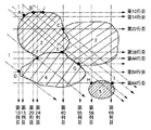
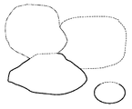
しかしながら、従来より知られるカラー画像のベクトル化方法においては、色空間上で既定される色領域に属する画素からなる領域毎に輪郭形状をベクトル化するのが基本である。そのため、それぞれの領域の輪郭形状をベジェ関数近似や平滑化処理すると、読み取り画像上で隣接する色領域間の輪郭が必ずしも同一の状態の輪郭形状に近似や平滑化がされずに、隙間や重なりが生じてしまうという問題があった。この様子を、図57と図58に示した。図57は、入力画像から色空間上で既定される色領域に属する画素からなる領域毎に輪郭形状を抽出した例を示している。ここで、背景の白地を数えないものとすると、入力画像上では、隣接する(重なる)色領域が3つ存在している。 However, in a conventionally known color image vectorization method, the contour shape is basically vectorized for each region composed of pixels belonging to a color region defined in the color space. Therefore, if the contour shape of each region is subjected to Bezier function approximation or smoothing processing, the contour between adjacent color regions on the scanned image is not necessarily approximated or smoothed to the contour shape in the same state, and gaps or overlaps are obtained. There was a problem that would occur. This is shown in FIG. 57 and FIG. FIG. 57 shows an example in which a contour shape is extracted for each area composed of pixels belonging to a color area defined in the color space from the input image. Here, if the white background is not counted, there are three adjacent (overlapping) color regions on the input image.
図58は、色領域に属する画素からなる領域毎に輪郭形状をベクトル化し、平滑化(関数近似)した場合の例を示しており、各領域間に隙間や重なりが生じてしまっている。 FIG. 58 shows an example in which the contour shape is vectorized and smoothed (function approximation) for each region composed of pixels belonging to the color region, and gaps or overlaps are generated between the regions.
本発明は上記の課題を解決するためになされたものであり、複数の色領域から構成されるカラー画像から、より適切に各色領域をベクトル化することができる画像処理装置及びその制御方法、プログラムを提供することを目的とする。 The present invention has been made to solve the above-described problem, and an image processing apparatus capable of more appropriately vectorizing each color area from a color image composed of a plurality of color areas, a control method therefor, and a program The purpose is to provide.
上記の目的を達成するための本発明による画像処理装置は以下の構成を備える。即ち、 前記画像を構成する各画素の属性情報に基づいて、前記画像を複数の領域に分割する分割手段と、
前記分割手段により分割した各領域の境界線に関する領域境界情報を抽出する抽出手段と、
前記抽出手段により抽出した領域境界情報に基づいて、前記境界線の交点を同定する交点情報生成手段と、
前記交点情報生成手段で同定した交点を端点として、前記境界線における前記端点間の部分毎に、関数近似処理を実行することにより、当該関数近似された端点間毎の境界線を示す端点間ベクトルデータを生成する端点間ベクトル生成手段と、
前記端点間ベクトル生成手段により生成した端点間ベクトルデータを用いて、前記分割手段により分割された各領域を囲む領域別のベクトルデータを生成する領域別ベクトル生成手段と
を備え、
前記端点間ベクトル生成手段で前記関数近似処理により生成される前記端点間ベクトルデータの端点の位置は、前記関数近似処理の実行前の前記端点の位置から変化しない。
In order to achieve the above object, an image processing apparatus according to the present invention comprises the following arrangement. A dividing unit that divides the image into a plurality of regions based on attribute information of each pixel constituting the image;
Extraction means for extracting region boundary information relating to the boundary lines of each region divided by the dividing unit;
Based on the region boundary information extracted by the extraction means, intersection information generating means for identifying the intersection of the boundary lines;
As the end point of intersection identified in the intersection information generating means for each portion between the end points of the boundary line, by performing function approximation processing, endpoint-to-endpoint vector indicating the boundaries of each among the function approximated endpoint Endpoint-to-endpoint vector generating means for generating data;
Using region-to-endpoint vector data generated by the endpoint-to-endpoint vector generating unit, and generating region-specific vector data surrounding each region divided by the dividing unit ,
The position of the end point of the end point vector data generated by the function approximating process by the end point vector generating means does not change from the position of the end point before execution of the function approximating process .
本発明によれば、複数の色領域から構成されるカラー画像から、より適切に各色領域をベクトル化することができる画像処理装置及びその制御方法、プログラムを提供できる。 ADVANTAGE OF THE INVENTION According to this invention, the image processing apparatus which can vectorize each color area more appropriately from the color image comprised from a several color area, its control method, and a program can be provided.
以下、本発明の実施の形態について図面を用いて詳細に説明する。 Hereinafter, embodiments of the present invention will be described in detail with reference to the drawings.
本発明は、画像上で隣接する色領域間の輪郭形状に関数近似や平滑化を施しても、隙間や重なりの発生がなく、良好なベクトル化(ベクトル処理)が可能な技術について提供する。本発明では、カラー画像、とりわけ、ディジタルカメラ等により撮影された自然画像に比べて色数の少ないイラスト画像のベクトル化について提供する。 The present invention provides a technique that allows good vectorization (vector processing) without generating gaps or overlapping even if function approximation or smoothing is applied to the contour shape between adjacent color regions on an image. The present invention provides vectorization of color images, especially illustration images having fewer colors than natural images taken by a digital camera or the like.
尚、各実施形態で説明するベクトルとは、ビットマップ画像データを作成する際に用いられる数式等の描画コマンドで表現されたデータ(ベクトルデータ)を意味するものである。また、ベクタ画像データをビットマップ画像データに変換することを、ラスタ化やラスタライズという。そのため、このビットマップ画像データは、ラスタデータと呼ばれることもある。 The vector described in each embodiment means data (vector data) expressed by a drawing command such as a mathematical formula used when creating bitmap image data. Also, converting vector image data into bitmap image data is called rasterization or rasterization. Therefore, this bitmap image data is sometimes called raster data.
また、以下の説明では、ベクトルデータのことを、単にベクトルと略称する。 In the following description, vector data is simply abbreviated as a vector.
<実施形態1>
図1は本発明の実施形態1の画像処理装置の機能構成を示すブロック図である。
<
FIG. 1 is a block diagram showing a functional configuration of the image processing apparatus according to the first embodiment of the present invention.
同図において、11は、入力としての処理対象画像を獲得するカラー画像獲得部である。12は、カラー画像獲得部11で獲得された画像を、同色領域とみなせる画素の連結としての部分領域に分割する領域同定部である。ここで、同色領域とみなせるとは、画素の特徴量(例えば、色情報(例えば、RGB値))が所定範囲内に含まれるものを、同一の画素の特徴量を有している領域と判定することである。
In the figure,
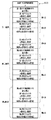
この領域同定部12は、領域分割部121と領域テーブル生成部122を備える。領域分割部121は、色情報に基づき幾何学的に連結した同色領域とみなせる画素の集まりに画像を分割する。また、領域テーブル生成部122は、領域分割部121から得られる各領域とそれら各領域の色情報(属性情報(例えば、RGB値))の対応づけ情報を、例えば、図2に示すテーブル形式(領域テーブル201)で生成する。
The
20は、領域同定部12で同定された各領域間の領域境界を1画素幅の細線で構成した領域境界細線画像を生成する領域境界細線画像生成部である。領域境界細線画像生成部20は、領域境界情報抽出部210、交点情報生成部220及び境界線画像生成部230を備える。
領域境界情報抽出部210は、領域同定部12で同定された各領域間の領域境界となる境界画素とそれらの各境界画素が隔てる領域間を示す領域境界情報を抽出する。また、交点情報生成部220は、領域境界画素を4−連結化した領域境界線の分岐点となる領域境界線の交点を示す交点情報を生成する。換言すれば、互いに異なる領域間の境界において、互いに異なる境界の交点を示す交点情報を生成する。また、境界線画像生成部230は、抽出された領域境界情報と生成された交点情報とから、領域境界細線画像を生成する。
The region boundary
領域境界情報抽出部210は、水平方向境界点抽出部211、水平方向境界点テーブル生成部212、垂直方向境界点抽出部213、垂直方向境界点テーブル生成部214、斜め方向境界点抽出部215及び斜め方向境界点テーブル生成部216を備える。
The region boundary
水平方向境界点抽出部211は、例えば、図3に示すように、領域同定部12により同定された同色領域とみなせる画素の連結としての部分領域で構成される領域同定結果画像を、水平方向に走査したときの各走査線上での領域間の境界となる画素を抽出する。即ち、水平方向における、ある部分領域から他の部分領域への切り替わりになる画素を抽出する。
For example, as illustrated in FIG. 3, the horizontal direction boundary
水平方向境界点テーブル生成部212は、水平方向境界点抽出部211で抽出された水平方向境界点の各点(画素)に関する情報を、図4に示す水平方向境界点テーブル401として生成する。
The horizontal boundary point
垂直方向境界点抽出部213は、例えば、図3に示すように、領域同定部12により同定された同色領域とみなせる画素の連結としての部分領域で構成される領域同定結果画像を、垂直方向に走査したときの各走査線上での領域間の境界となる画素を抽出する。即ち、垂直方向における、ある部分領域から他の部分領域への切り替わりになる画素を抽出する。
For example, as illustrated in FIG. 3, the vertical boundary
垂直方向境界点テーブル生成部214は、垂直方向境界点抽出部213で抽出された垂直方向境界点の各点(画素)に関する情報を、図4に示す垂直方向境界点テーブル402として生成する。
The vertical boundary point
斜め方向境界点抽出部215は、例えば、図3に示すように、領域同定部12により同定された同色領域とみなせる画素の連結としての部分領域で構成される領域同定結果画像を、斜め方向に走査したときの斜め走査線上での領域間の境界となる画素を抽出する。即ち、斜め方向における、ある部分領域から他の部分領域への切り替わりになる画素を抽出する。
For example, as illustrated in FIG. 3, the oblique direction boundary
斜め方向境界点テーブル生成部216は、斜め方向境界点抽出部215で抽出された斜め方向境界点の各点(画素)に関する情報を、図4に示す斜め方向境界点テーブル403として生成する。
The diagonal direction boundary point
交点情報生成部220は、交点同定部221と交点テーブル生成部222を備える。
The intersection
交点同定部221は、図4の水平方向境界点テーブル401、垂直方向境界点テーブル402及び斜め方向境界点テーブル403とから、交点情報を生成する。
The
具体的には、図5に示すように、3つのテーブル401〜403上の少なくとも2つ以上のテーブル上に存在する境界点の内、それが属する2つ以上のテーブル上でそれぞれの隣接する領域番号の組み合わせが完全には一致していない境界点を探索する。即ち、異なる領域番号の組み合わせが存在するような境界点を探索し、それを交点(交点情報)とする。図5の例では、C及びEが交点となる。 Specifically, as shown in FIG. 5, of the boundary points existing on at least two tables on the three tables 401 to 403, each adjacent area on two or more tables to which it belongs. Search for boundary points where the combination of numbers does not completely match. That is, a boundary point where a combination of different area numbers exists is searched for and used as an intersection (intersection point information). In the example of FIG. 5, C and E are intersections.
交点テーブル生成部222は、交点同定部221で同定された交点について、その交点が属するテーブル上の隣接する領域番号の内の少なくともいずれかには表記されている領域番号を全て抜き出す。そして、これにより、その交点の隣接する領域の領域番号の全てを対応する交点とともに管理する、図6に示す交点テーブル601を生成する。
The intersection
境界線画像生成部230は、境界線画像描画部231と境界線画像細線化部232を備える。
The boundary line
境界線画像描画部231は、生成された領域境界情報と生成された交点情報とから、領域境界画素を4−連結化した境界線画像を生成する。また、境界線画像細線化部232は、得られた境界線画像に4−連結の状態を保った細線化を行ない、4−連結の領域境界細線画像を生成する。
The boundary line
例えば、境界線画像細線化部232は、境界線画像描画部231にて生成される領域境界画素を4−連結化した境界線画像(2値画像)を、公知の2値画像細線化手法により、4−連結に細線化された2値画像としての4−連結の領域境界細線画像を出力する。
For example, the boundary line
ここで、公知の2値画像細線化手法としては、Hilditch法がある。これは、例えば、酒井幸市著「ディジタル画像処理の基礎と応用」第2版,ISBN4−7898−3707-6,CQ出版社,2004年2月1日発行,P.51−P.54,等)に記載されている。 Here, as a known binary image thinning method, there is a Holditch method. This is described in, for example, Yukiichi Sakai, “Basics and Applications of Digital Image Processing” 2nd Edition, ISBN 4-7898-3707-6, CQ Publisher, issued February 1, 2004, P.A. 51-P. 54, etc.).
一例として、図7(a)に示される2値画像を境界線画像細線化部232に入力した場合には、境界線画像細線化部232から出力されることになる細線化済画像は、図7(b)となる。
As an example, when the binary image shown in FIG. 7A is input to the boundary line
図1の説明に戻る。 Returning to the description of FIG.
30は、領域境界細線画像生成部20で生成された4−連結の領域境界細線画像を、交点から他の交点までを繋ぐ4−連結の細線毎に、其々の交点を端点とした端点間ベクトルの集まりとしてベクトル化する端点間ベクトル生成部である。
30 is an interval between the end points of each 4-connected thin line that connects the 4-connected region boundary thin-line image generated by the region boundary thin-line
端点間ベクトル生成部30は、端点間ベクトル抽出部310と端点間ベクトル関数近似(平滑)部320を備える。
The endpoint
端点間ベクトル抽出部310は、4−連結の領域境界細線画像を、交点から他の交点までを繋ぐ4−連結の細線毎に、其々の交点をベクトルの端点として、端点間を繋ぐ各細線の画素の中心位置上を通過する線芯ベクトルを端点間ベクトルとして抽出する。
The inter-endpoint
端点間ベクトル関数近似(平滑)部320は、抽出された端点間ベクトルを、端点から端点までの間が、端点部分が端点として保存された形で関数近似する。即ち、端点部分がベジェ曲線のアンカーポイントとなるようにベジェ関数近似し、関数近似(平滑化)済端点間ベクトルを生成する。
The end point vector function approximation (smoothing)
ここで、端点間ベクトル抽出部310は、図8に示すように、端点間毎輪郭(周回)ベクトル抽出部3110と端点間毎線芯(周回)ベクトル生成部3120とを備える。
Here, the inter-endpoint
端点間毎輪郭(周回)ベクトル抽出部3110は、4−連結の状態を保って細線化されている領域境界細線画像を入力する。次に、1回のラスタ走査のみにより、処理対象の細線化済2値画像中の線図形を、それらを構成している端点や交点間をつなぐ独立した線や閉曲線毎のそれぞれに対応したベクトル列の集まり(以降、「端点間毎線素粗輪郭ベクトル」という)として抽出する。そして、その処理結果を出力する。
The contour (circumference)
尚、出力される処理結果には、ベクトル列のそれぞれを構成する各ベクトルが、処理対象の線図形の端点(交点)位置に対応する部分から抽出されたものか否か等を表す情報(以降、「付与情報」ともいう)が含まれる。 The output processing result includes information indicating whether or not each vector constituting each vector string is extracted from a portion corresponding to the end point (intersection) position of the line figure to be processed (hereinafter referred to as the processing result) , Also referred to as “grant information”).
また、端点間毎線芯(周回)ベクトル生成部3120は、端点間毎輪郭(周回)ベクトル抽出部3110より得られる付与情報と端点間毎線素粗輪郭ベクトル(以降、これらを合わせて「端点間毎輪郭(周回)ベクトル」という)を入力する。そして、付与情報を利用して、一画素幅の幅を持った輪郭(周回)ベクトルの各ベクトルの位置をそれぞれ半画素分ずつ相応する方向へ予め定める規則により微調整する。これによって、幅0に線芯化された端点間毎線芯(周回)化済ベクトルを生成する。
Further, the inter-endpoint line-core (circumference)
図7(c)は、図7(b)の画像を入力2値画像とした際の端点間毎輪郭(周回)ベクトル抽出部3110から出力される端点間毎輪郭(周回)ベクトルを輪郭画像として描画して可視化したものである。また、図7(d)は、図7(c)の画像を入力した際の端点間毎線芯(周回)ベクトル生成部3120から出力される端点間毎線芯(周回)化済ベクトルを線画像として描画して可視化したものである。
FIG. 7C shows an end-to-end-point contour (circumference)
また、端点間ベクトル関数近似(平滑)部320は、端点間毎補助ベクトル入り(周回)ベクトル生成部3210、端点間毎補助ベクトル入り(周回)ベクトル平滑化部3220、端点間毎平滑化済ベクトル同定(非周回化)部3230を備える(図8参照)。
In addition, the inter-endpoint vector function approximation (smoothing)
ここで、端点間毎補助ベクトル入り(周回)ベクトル生成部3210は、端点間毎線芯(周回)ベクトル生成部3120より得られる端点間毎線芯(周回)化済ベクトルを入力する。そして、次工程の処理をする端点間毎補助ベクトル入り(周回)ベクトル平滑部3220により平滑化(関数近似)処理される際に、端点部分に相当するベクトルが、他のベクトルと統合されて端点位置が不明にならぬようにするための補助ベクトルを挿入する。つまり、端点部分に相当する部分が端点として保存される(ベジェ曲線のアンカーポイントとなる)ように補助ベクトルを挿入することにより、端点間毎補助ベクトル入り(周回)ベクトルを生成する。
Here, the inter-endpoint auxiliary vector-containing (circumference) vector generation unit 3210 receives the inter-endpoint inter-endpoint line-by-end (circumference) vector generation vector obtained from the end-point-to-endpoint line-by-end (circulation)
加えて、端点間毎補助ベクトル入り(周回)ベクトル生成部3210は、補助ベクトルを挿入された各端点間毎補助ベクトル入り(周回)ベクトルのそれぞれに対し、どのベクトルが端点部にあたるかを明示する始端点・終端点情報をも生成する。 In addition, the inter-endpoint auxiliary vector-containing (circumference) vector generation unit 3210 clearly indicates which vector corresponds to the end-point portion for each inter-endpoint auxiliary vector-containing (circular) vector into which the auxiliary vector is inserted. Start point / end point information is also generated.
図7(e)は、図7(d)の画像を入力した際の端点間毎補助ベクトル入り(周回)ベクトル生成部3210から出力される端点間毎補助ベクトル入り(周回)ベクトルを線画像として描画して可視化したものである。 FIG. 7E shows an inter-endpoint auxiliary vector-containing (circumference) vector output from the end-point auxiliary vector (circumference) vector output from the end-point auxiliary vector when the image of FIG. 7D is input as a line image. It is drawn and visualized.
端点間毎補助ベクトル入り(周回)ベクトル平滑部3220は、端点間毎補助ベクトル入り(周回)ベクトル生成部3210より端点間毎補助ベクトル入り(周回)ベクトルを入力する。次に、各(周回)ベクトル毎に平滑化(関数近似)処理を行うことによって、平滑化された平滑化済端点間毎補助ベクトル入り(周回)ベクトルを生成する。そして、それを、次工程の処理をする端点間毎平滑化済ベクトル同定(非周回化)部3230に出力する。
The inter-endpoint auxiliary vector-containing (circumferential)
端点間毎平滑化済ベクトル同定(非周回化)部3230は、端点間毎補助ベクトル入り(周回)ベクトル平滑部3220より平滑化(関数近似)済端点間毎補助ベクトル入り(周回)ベクトルを入力する。また、端点間毎平滑化済ベクトル同定(非周回化)部3230は、端点間毎補助ベクトル入り(周回)ベクトル生成部3210より始端点・終端点情報を入力する。
A smoothed vector identification (non-circularization) unit between
そして、端点間毎平滑化済ベクトル同定(非周回化)部3230は、各平滑化済の(周回)ベクトル毎にそれぞれ始端点と終端点となるベクトルを同定して、始端点と終端点の間のみの部分の非周回型のベクトル列を生成する。
Then, the smoothed vector identification (non-circularization)
図7(f)は、図7(e)の画像を入力した際の端点間毎平滑化済ベクトル同定(非周回化)部3230から出力される平滑化済ベクトルを線画像として描画して可視化したものである。
FIG. 7F shows the smoothed vector output from the smoothed vector identification (non-circularization)
図1の説明に戻る。 Returning to the description of FIG.
40は、各領域毎にそれを取り囲む平滑化(関数近似)済端点間ベクトル列とその内部色とでなる領域ベクトルに変換する領域別ベクトル生成部である。この処理は、端点間ベクトル生成部30から得る平滑化(関数近似)済端点間ベクトルと、領域境界細線画像生成部20から得る各交点が隣接する領域の領域番号情報と、領域同定部12から得る各領域とそれらの色情報(属性情報)の対応づけ情報を用いて行う。
領域別ベクトル生成部40は、領域境界ベクトル列同定部410と、領域属性付与部420とを備える。
The region-specific
領域境界ベクトル列同定部410は、各領域毎にそれを取り囲む関数近似(平滑化)済端点間ベクトル列を同定する。この処理は、端点間ベクトル生成部30で生成された関数近似(平滑化)済端点間ベクトルと、領域同定部12から得る各領域とそれらの色情報(属性情報)の対応づけ情報を用いて行われる。
The region boundary vector
領域属性付与部420は、各領域を取り囲む平滑化(関数近似)済端点間ベクトル列にその内部の色情報を付与して、各領域毎にそれを取り囲む平滑化(関数近似)済端点間ベクトル列とその色情報からなる領域ベクトルを生成する。この処理は、領域境界ベクトル列同定部410で同定された各領域毎の平滑化(関数近似)済端点間ベクトル列と、領域同定部12から得る各領域とそれらの色情報(属性情報)の対応づけ情報を用いて行う。
The region attribute assigning
次に、図1の画像処理装置のハードウェア構成について、図9を用いて説明する。 Next, the hardware configuration of the image processing apparatus in FIG. 1 will be described with reference to FIG.
図9は本発明の実施形態1の画像処理装置のハードウェア構成を示す図である。 FIG. 9 is a diagram illustrating a hardware configuration of the image processing apparatus according to the first embodiment of the present invention.
同図において、518は、図9に示す各種構成要素を相互に接続するためのバスである。1はスキャナである。2は画像メモリであり、3は画像入出力I/Oである。画像メモリ2は画像入出力I/O3を介して、スキャナ1で読み取られたカラー画像を保持する。図1のカラー画像獲得部11は、このスキャナ1、画像入出力I/O3及び画像メモリ2によって実現される。
In the figure,
また、画像メモリ2は、領域同定部12により生成される同色領域とみなせる画素の連結領域を部分領域として構成される領域同定結果画像を保持する。また、画像メモリ2は、領域境界細線画像生成部20の境界線画像生成部230で生成される境界線画像や、得られた境界線画像に対する、4−連結の状態での細線化によって生成される4−連結の領域境界細線画像を保持する。
In addition, the
このように、画像メモリ2は、領域同定部12や領域境界細線画像生成部20、端点間ベクトル生成部30を構成する一部としても機能する。
As described above, the
4は通信I/Fであり、ネットワーク等を経由して、システムの外部と通信する。519はCPUである。520はRAMで、例えば、ワーキングメモリとして機能する。6はROMであり、後に説明する手順に沿ってCPU519で実行されるプログラムや予め定められるパラメータやデータ等を格納している。
A communication I /
ここで、画像メモリ2と、CPU519やRAM520、ROM6により、図1の領域同定部12、領域境界細線画像生成部20、端点間ベクトル生成部30が構成されるとともに、領域別ベクトル生成部40も実現される。
Here, the
521はハードディスク装置522とのディスクI/O(入出力回路)である。
以下、画像処理装置の動作について、図10を用いて説明する。 Hereinafter, the operation of the image processing apparatus will be described with reference to FIG.
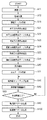
図10は本発明の実施形態1の画像処理装置の動作を示すフローチャートである。 FIG. 10 is a flowchart showing the operation of the image processing apparatus according to the first embodiment of the present invention.
尚、この処理は、例えば、CPU519が、ROM6に記憶されているプログラムを実行することによって、図1に示される各種機能構成によって実現される。
Note that this processing is realized by the various functional configurations shown in FIG. 1 by the
まず、ステップS11で、カラー画像獲得部11が、入力としての処理対象カラー画像を入力する。次に、ステップS12とステップS13は、領域同定部12での処理内容を実行する。即ち、ステップS11で入力した画像を領域分割処理し、領域分割処理結果をRAM520に保存する。
First, in step S11, the color
より具体的には、ステップS12で、領域分割部121が、色情報に基づき幾何学的に連結した同色領域とみなすことができる画素の集まりに画像を分割する。そして、ステップS13で、領域テーブル生成部122が、得られる各領域内の画素の色平均値をもって、その領域の色情報(属性情報)とし、図2に示す領域テーブル201を作成して、RAM520上に保存する。ステップS12の領域分割処理の詳細については後述する。
More specifically, in step S12, the
次に、ステップS21からステップS26は、領域境界情報抽出部210での処理内容を実行する。即ち、ステップS12で同定された各領域間の領域境界となる境界画素とそれらの各境界画素が隔てる領域間を示す領域境界情報を抽出する。
Next, in steps S21 to S26, the processing content in the region boundary
まず、ステップS21で、水平方向境界点抽出部211が、同色領域とみなすことができる画素の連結としての部分領域で構成される領域同定結果画像を、水平方向に走査したときの各走査線上での領域間の境界となる画素を抽出する。即ち、ある領域から他の領域への切り替わりになる水平方向境界点の画素を抽出する。ステップS22で、水平方向境界点テーブル生成部212が、抽出した水平方向境界点の各点に関する座標と隣接する領域番号を用いて、水平方向境界点テーブル401(図4)を生成する。
First, in step S21, the horizontal boundary
ステップS23で、垂直方向境界点抽出部213が、同色領域とみなすことができる画素の連結としての部分領域で構成される領域同定結果画像を、垂直方向に走査したときの各走査線上での領域間の境界となる垂直方向境界点の画素を抽出する。ステップS24で、垂直方向境界点テーブル生成部214が、抽出した垂直方向境界点の各点に関する座標と隣接する領域番号を用いて、垂直方向境界点テーブル402(図4)を生成する。
In step S23, the area on each scanning line when the vertical direction boundary
ステップS25で、斜め方向境界点抽出部215が、同色領域とみなすことができる画素の連結としての部分領域で構成される領域同定結果画像を、斜め方向に走査したときの各走査線上での領域間の境界となる斜め方向境界点の画素を抽出する。ステップS26で、斜め方向境界点テーブル生成部216が、抽出した斜め方向境界点の各点に関する座標と隣接する領域番号を用いて、斜め方向境界点テーブル403(図4)を生成する。
In step S25, the region on each scanning line when the oblique direction boundary
尚、ステップS21、ステップS23とステップS25の境界点抽出処理の詳細については後述する。 The details of the boundary point extraction process in steps S21, S23, and S25 will be described later.
次に、ステップS30とS31は、交点情報生成部220での処理内容を実行する。即ち、領域境界画素を4−連結化した領域境界線の分岐点となる領域境界線の交点の情報を生成する。
Next, steps S30 and S31 execute the processing contents in the intersection
まず、ステップS30で、交点同定部221が、水平方向境界点テーブル401、垂直方向境界点テーブル402及び斜め方向境界点テーブル403とから、交点を抽出する。
First, in step S <b> 30, the
具体的には、3つのテーブル401〜403上で2つ以上のテーブルに存在する境界点の内、各テーブル401〜403それぞれでの隣接する領域番号とから3つ以上の領域番号を持つ境界点を探索して、それを交点とする。 Specifically, among the boundary points existing in two or more tables on the three tables 401 to 403, the boundary points having three or more area numbers from the adjacent area numbers in the respective tables 401 to 403. And make it the intersection.
尚、3つのテーブル上で2つ以上のテーブルに存在する境界点とは、水平境界点かつ垂直方向境界点、水平方向境界点かつ斜め方向境界点、垂直方向境界点かつ斜め方向境界点、あるいは水平方向境界点かつ垂直方向境界点かつ斜め方向境界点のいずれかである。 The boundary points existing in two or more tables on the three tables are a horizontal boundary point and a vertical boundary point, a horizontal boundary point and an oblique boundary point, a vertical boundary point and an oblique boundary point, or Any of a horizontal boundary point, a vertical boundary point, and an oblique boundary point.
ステップS31で、交点テーブル生成部222が、ステップS30で同定された交点に基づいて、交点テーブル601を生成する。
In step S31, the intersection
具体的には、水平方向境界点テーブル401での隣接する領域番号と垂直方向境界点テーブル402での隣接する領域番号と斜め方向境界点テーブル403での隣接する領域番号の少なくともいずれかには表記されている領域番号を全て抜き出す。これにより、その交点の隣接する領域の領域番号の全てとして、図6の交点テーブル601を生成する。 Specifically, at least one of the adjacent area number in the horizontal boundary point table 401, the adjacent area number in the vertical boundary point table 402, and the adjacent area number in the oblique direction boundary point table 403 is described. Extract all the region numbers. As a result, the intersection table 601 in FIG. 6 is generated as all the region numbers of the regions adjacent to the intersection.
尚、ステップS30の交点抽出処理の詳細については後述する。 Details of the intersection extraction process in step S30 will be described later.
ステップ50からステップS80は、境界線画像生成部230と端点間ベクトル生成部30の処理内容を実行する。即ち、ステップS12で生成された領域境界情報とステップS30で獲得した交点情報とから、領域境界細線画像を生成し、各端点間ベクトルを生成する。
From
まず、ステップS50で、境界線画像描画部231を実行する。即ち、領域境界情報から、領域境界画素を4−連結化した境界線ビットマップ画像(境界線画像)を生成する。ステップS60で、境界線画像細線化部232を実行する。即ち、4−連結化した境界線画像から領域境界細線画像を生成する。ステップS70で、端点間ベクトル生成部30を実行する。即ち、領域境界細線画像を、交点と交点の間を繋ぐ境界線画像毎に、順次に端点間ベクトルを生成する。
First, in step S50, the boundary line
ステップS80で、全ての境界線について端点間ベクトル化の処理が終了したか否かを判定する。この処理では、ステップS31で生成された交点テーブル601にあるすべての交点と交点の間を繋ぐ境界線画像の端点間ベクトル生成処理が終了していない場合(ステップS80でNO)、まだ未処理の境界線があると判定する。その場合、ステップS50に戻り、以上の処理を繰り返し実行する。一方、全ての交点と交点の間を繋ぐ境界線画像の端点間ベクトル生成処理が終了している場合(ステップS80でYES)、未処理の境界線がないと判定し、ステップS100へ進む。 In step S80, it is determined whether or not the inter-endpoint vectorization processing has been completed for all boundary lines. In this processing, if the inter-endpoint vector generation processing for the boundary line image connecting all the intersections in the intersection table 601 generated in step S31 is not completed (NO in step S80), the processing is not yet performed. It is determined that there is a boundary line. In that case, the process returns to step S50, and the above processing is repeated. On the other hand, when the inter-endpoint vector generation processing of the boundary line image connecting all the intersections is completed (YES in step S80), it is determined that there is no unprocessed boundary line, and the process proceeds to step S100.
ステップS50の境界線ビットマップ生成処理では、図4の各境界点テーブル401〜403に保持される水平方向境界点、垂直方向境界点、斜め方向境界点を所望とする領域境界毎に、これらテーブルの隣接する領域番号の等しいものを全て順次探し出す。そして、その探し出した境界点を用いて、ビットマップ画像を生成する。 In the boundary line bitmap generation processing in step S50, these tables are provided for each region boundary where horizontal boundary points, vertical boundary points, and oblique boundary points held in the boundary point tables 401 to 403 in FIG. 4 are desired. Are sequentially searched for all the adjacent region numbers having the same number. Then, a bitmap image is generated using the found boundary point.
即ち、後述する処理済チェックがなされていない境界点を、例えば、水平方向境界点テーブル401、垂直方向境界点テーブル402、斜め方向境界点テーブル403の順にサーチする。そして、最初に保持される処理済のチェックがされていない境界点を探して1点を描画する。続いて、その点の隣接する領域番号の組み合わせと同じ領域番号の組み合わせを持つ点を水平方向境界点テーブル401、垂直方向境界点テーブル402、斜め方向境界点テーブル403の全てにわたり、順次に探し出しては描画する。そして、条件に合う境界点を全て、その領域番号の組み合わせで示される領域間を分ける境界線として描画する。 That is, the boundary points that have not been checked as described below are searched in the order of, for example, the horizontal boundary point table 401, the vertical boundary point table 402, and the oblique direction boundary point table 403. Then, a boundary point that is first checked and is not checked for processing is searched and one point is drawn. Subsequently, a point having the same combination of area numbers as the combination of adjacent area numbers of the point is sequentially searched through all of the horizontal boundary point table 401, the vertical boundary point table 402, and the diagonal boundary point table 403. Draw. Then, all boundary points that meet the conditions are drawn as boundary lines that divide the areas indicated by the combination of the area numbers.
尚、境界線として描画された境界点は、既に境界線ビットマップ生成処理が済んだものとして、各境界点テーブル401〜403の境界点の其々に対応する処理済チェックフラグ欄(不図示)にチェックする(フラグセットする)。これにより、処理済であることを明示する。尚、この処理済チェックフラグがチェックされていない境界点が存在しない場合には、全ての境界点がビットマップとして生成済みであることを意味する。 Note that the boundary points drawn as boundary lines have already been subjected to the boundary line bitmap generation processing, and processed check flag fields (not shown) corresponding to the boundary points in the boundary point tables 401 to 403, respectively. Check (set flag). This clearly indicates that it has been processed. If there is no boundary point for which the processed check flag is not checked, it means that all boundary points have been generated as bitmaps.
尚、この処理で描画される境界点のビットマップ画像は、例えば、後述する図50(e)の、ハッチングパターンが付されている画素(1)の部分に示されるような、ある交点間を結ぶ4−連結化した領域となる。しかしながら、必ずしも、一画素幅の線画像となるとは限らず、一部2画素幅以上になる場合がありえる。 Note that the bitmap image of the boundary point drawn by this processing is, for example, between certain intersections as shown in the pixel (1) portion with a hatching pattern in FIG. 4-connected area. However, it is not always a line image with a width of one pixel, and a part of the line image may have a width of 2 pixels or more.
ステップS60の境界線画像細線化処理では、ステップS50で得られる境界線ビットマップ画像(2値画像)を、公知の2値画像細線化手法で、4−連結に細線化された2値画像として出力する。 In the boundary line image thinning process in step S60, the boundary line bitmap image (binary image) obtained in step S50 is converted into a binary image that has been thinned into 4-links by a known binary image thinning method. Output.
次に、ステップS70の端点間ベクトル生成処理について詳述する。 Next, the inter-endpoint vector generation processing in step S70 will be described in detail.
上述したように、ステップS70では、端点間ベクトル生成部30を実行する。即ち、領域境界細線画像を、交点と交点の間を繋ぐ境界線画像毎に、順次に端点間ベクトルを生成する。端点間ベクトル生成部30は、図8に示したように、端点間ベクトル抽出部310と端点間ベクトル関数近似(平滑)部320と備える。さらに、端点間ベクトル抽出部310は、端点間毎輪郭(周回)ベクトル抽出部3110と端点間毎線芯(周回)ベクトル生成部3120とを備える。また、端点間ベクトル関数近似(平滑)部320は、端点間毎補助ベクトル入り(周回)ベクトル生成部3210、端点間毎補助ベクトル入り(周回)ベクトル平滑化部3220、端点間毎平滑化済ベクトル同定(非周回化)部3230を備える。
As described above, in step S70, the endpoint
以下、主として、図11〜図27を用いて端点間毎輪郭(周回)ベクトル抽出部3110での処理内容を説明する。
Hereinafter, the processing contents in the contour (circumference)
実施形態1では、図11に示すように、2値画像における注目画素101と、その近傍の8個の画素の状態を見て処理を進めるもので、注目画素をラスタ走査し、1画素毎にずらしながら画像全体の処理を逐次行う。
In the first embodiment, as shown in FIG. 11, the process proceeds by looking at the state of the
図11において、×は注目画素101を示しており、「0」及び「2」で示された位置は、主走査方向に対し注目画素101と同じ位置にあり、副走査方向のそれぞれ1ラスタ前の画素(0)及び1ラスタ先の画素(2)を示す。「1」及び「3」で示された位置は、注目画素101と同一のラスタ上にあり、それぞれ1画素前の画素(3)及び1画素先の画素(1)を示している。
In FIG. 11, “x” indicates the
更に、「A」及び「B」は、主走査方向に1画素先の位置にあり、それぞれ1ラスタ前及び1ラスタ先の位置にある画素を示し、「C」及び「D」は主走査方向の1画素前の位置にある画素で、それぞれ1ラスタ先及び1ラスタ前の位置にある画素を示している。 Further, “A” and “B” are pixels one pixel ahead in the main scanning direction, respectively, and indicate pixels at one raster before and one raster ahead, respectively, and “C” and “D” are main scanning directions. The pixels at the position one pixel before are shown as the pixels one raster ahead and one raster ahead, respectively.
次に注目画素101及びその近傍の8画素の状態に応じた、それぞれの場合の処理を説明する。
Next, processing in each case according to the state of the pixel of
注目画素101が白画素である場合は、その処理を終了してラスタ走査を1画素分進め、注目画素位置を更新する。
If the
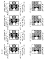
注目画素101が黒画素の場合は、近傍の画素の状態によって、以下の処理を行う。ここで、図12〜図27に各状態における処理内容を示してある。図12〜図27において、斜めのチェッカーパターンで示される○印は黒画素を示し、点線の○印は白画素を示している。「d」は「do no care」、即ち、「d」の表示のある位置の画素は白画素でも黒画素でも構わないことを意味している。
When the pixel of
また、図12〜図27の各画素マトリクスにおいて、●印と○印は、横方向ベクトルの始点及び縦方向ベクトルの終点を示していて、▲印と△印は縦方向ベクトルの始点及び横方向ベクトルの終点を示している。これらのベクトルの始点・終点間の実線矢印は、始点及び終点共に定まった、矢印の向く方向の輪郭ベクトルを示している。一方、点線矢印は、始点もしくは終点のいずれか一方のみが定まった、矢印の向く方向の輪郭ベクトルを示している。これら輪郭ベクトルの始点及び終点を総称して、以降、輪郭点と呼ぶことにする。尚、図12、図17、図22の画素マトリクスパターンの場合は、輪郭ベクトルを抽出しない。 In each pixel matrix of FIGS. 12 to 27, the ● mark and the ○ mark indicate the start point of the horizontal vector and the end point of the vertical vector, and the ▲ mark and Δ mark indicate the start point and the horizontal direction of the vertical vector. Indicates the end point of the vector. A solid line arrow between the start point and the end point of these vectors indicates a contour vector in the direction of the arrow determined for both the start point and the end point. On the other hand, a dotted arrow indicates a contour vector in the direction of the arrow in which only one of the start point and the end point is determined. The start point and end point of these contour vectors are collectively referred to as contour points hereinafter. In the case of the pixel matrix patterns of FIGS. 12, 17, and 22, no contour vector is extracted.
また、●印と▲印は端点部から抽出されるベクトルの始点・終点で、それぞれ端点部から抽出される横方向ベクトルの始点及び縦方向ベクトルの終点、端点部から抽出される縦方向ベクトルの始点及び横方向ベクトルの終点であることを示している。 The ● and ▲ marks are the start and end points of the vector extracted from the end point. The start and end points of the horizontal and vertical vectors extracted from the end point, respectively. It shows the start point and the end point of the horizontal vector.
図12〜図27の画素マトリクスに応じて抽出される輪郭点には、対応付けられる付与情報として、図28の一覧表に示した輪郭点情報のいずれかが付記されている。この輪郭点情報が、各輪郭点情報に付記されて抽出される付与情報となる。 Any of the contour point information shown in the list of FIG. 28 is appended to the contour points extracted according to the pixel matrix of FIGS. This contour point information is added information that is appended to each contour point information and extracted.
図28の一覧表中のNo.01〜16に示される16種の輪郭点情報は、「xxx_yyy_zzz」または「xxx_yyy」なる形で表記されている。いずれも、「xxx」の部分は、対象の輪郭点が終点となるベクトルの向きを示し、「yyy」の部分は、同輪郭点が始点となるベクトルの向きを示している。上向きをUP、下向きをDOWN、右向きをRIGHT、左向きをLEFTと表現する。この場合、例えば、No.01〜03はいずれも、上向きベクトルの始点かつ右向きベクトルの始点になっている輪郭点であることを意味している。 No. in the list of FIG. The 16 types of contour point information shown in 01 to 16 are described in the form of “xxx_yyy_zzz” or “xxx_yyy”. In either case, the part “xxx” indicates the direction of the vector whose target contour point is the end point, and the part “yyy” indicates the direction of the vector whose starting point is the contour point. The upward direction is expressed as UP, the downward direction as DOWN, the right direction as RIGHT, and the left direction as LEFT. In this case, for example, no. Each of 01 to 03 means that the contour point is the starting point of the upward vector and the starting point of the right vector.
尚、「_zzz」の部分は、この付与情報をもつ輪郭点が、端点部から抽出されたものであることを意味していて、図28の端点情報の欄に記載してある。ここで、_TRは、線素の上端部の右側(Top Right)から抽出された端点であることを示している(図29(a)参照)。また、_LTは、線素の左端部の上側(Left Top)から抽出された端点であることを示している(図29(b)参照)。 The part “_zzzz” means that the contour point having the given information is extracted from the end point portion, and is described in the end point information column of FIG. Here, _TR indicates that it is an end point extracted from the right side (Top Right) of the upper end portion of the line element (see FIG. 29A). Moreover, _LT has shown that it is the end point extracted from the upper side (Left Top) of the left end part of a line element (refer FIG.29 (b)).
また、_RBは、線素の右端部の下側(Right Bottom)から抽出された端点であることを示している(図29(c)参照)。また、_BRは、線素の下端部の右側(Bottom Right)から抽出された端点であることを示している(図29(d)参照)。 Further, _RB indicates an end point extracted from the lower side (Right Bottom) of the right end portion of the line element (see FIG. 29C). Further, _BR indicates an end point extracted from the right side (Bottom Right) of the lower end portion of the line element (see FIG. 29D).
また、_LBは、線素の左端部の下側(Left Bottom)から抽出された端点であることを示している(図29(b)参照)。また、_BLは、線素の下端部の左側(Bottom Left)から抽出された端点であることを示している(図29(d)参照)。 Further, _LB indicates an end point extracted from the lower side (Left Bottom) of the left end portion of the line element (see FIG. 29B). Further, _BL indicates an end point extracted from the left side (Bottom Left) of the lower end portion of the line element (see FIG. 29D).
また、_RTは、線素の上端部の右側(Right Top)から抽出された端点であることを示している(図29(c)参照)。_TLは、線素の左端部の上側(Top Left)から抽出された端点であることを示している(図29(a)参照)。 Further, _RT indicates an end point extracted from the right side (Right Top) of the upper end portion of the line element (see FIG. 29C). _TL indicates an end point extracted from the upper left side (Top Left) of the line element (see FIG. 29A).
線素の端点ではない部分(以降、非端点部という)から抽出される輪郭点には、この「_zzz」部のない輪郭点情報が付与され、これらの例を図30(a)〜(d)に示している。 Contour point information without this “_zzzz” portion is given to contour points extracted from portions that are not end points of line elements (hereinafter referred to as non-end point portions), and examples of these are shown in FIGS. ).
但し、注目画素が黒画素の場合で、近傍の画素の状態によって、図12〜図27に各状態における輪郭点とその付与情報を抽出する際の実際の処理では、図28の輪郭点情報は「値」の欄の対応する位置に表記される数値で抽出されるように構成するものとする。 However, in the case where the pixel of interest is a black pixel, the contour point information shown in FIG. It shall be constituted so that it may be extracted by a numerical value written at a corresponding position in the “value” column.
図30において、斜めのチェッカーパターンで示される○印は黒画素を示し、点線の○印は白画を示している。 In FIG. 30, the circles indicated by the oblique checker pattern indicate black pixels, and the dotted circles indicate white images.
これら輪郭ベクトルの始点・終点位置は、主走査方向及び副走査方向共に、画素と画素の中間の位置にあるものとする。また、主走査方向及び副走査方向共に、画素のある位置は正整数で示され、画素位置を2次元の座標で表現をする。 The start point and end point position of these contour vectors are assumed to be in the middle position between pixels in both the main scanning direction and the sub-scanning direction. Further, in both the main scanning direction and the sub-scanning direction, a certain pixel position is indicated by a positive integer, and the pixel position is expressed by two-dimensional coordinates.
但し、ここでは小数の表現を避けるために便宜上、以降の画素位置を偶数のみで表現することにし、始点、終点の位置を奇数の整数で表現することにする。即ち、m画素×n画素の画像は、2m×2nの正の偶数(整数)の座標表現で表わすものとする。このように、主走査方向をx座標、副走査方向をy座標とした2次元座標であらわすとき、これ以降、2値画像は、それぞれがm画素よりなるnラスタで構成されるm×n画素(m,nは正の整数)で表現するものとする。また、第j番目のラスタの第i番目の画素位置を(2i,2j)(i,iは正の整数で、i≦m,j≦n)で表現するものとする。また、主走査方向(x座標)は左から右に向かう方向が正の方向であり、副走査方向(y座標)は上から下に向かう向きが正の方向である。 However, here, for the sake of convenience, in order to avoid the representation of decimal numbers, the subsequent pixel positions are represented by even numbers, and the positions of the start point and end point are represented by odd integers. That is, an image of m pixels × n pixels is represented by a coordinate expression of 2m × 2n positive even number (integer). Thus, when the two-dimensional coordinates are expressed with the x-coordinate in the main scanning direction and the y-coordinate in the sub-scanning direction, the binary image is m × n pixels each composed of n rasters each consisting of m pixels. (M and n are positive integers). Also, the i-th pixel position of the j-th raster is represented by (2i, 2j) (i, i are positive integers, i ≦ m, j ≦ n). The main scanning direction (x coordinate) is a positive direction from left to right, and the sub-scanning direction (y coordinate) is a positive direction from top to bottom.
以下、端点間毎輪郭(周回)ベクトル抽出部3110の一連の動作を、図31A〜図33に従って説明を加える。
Hereinafter, a series of operations of the contour (circumference)
実施形態1は、特許文献4に比し、4−連結に細線化された2値画像を端点、交点を検出しつつ、端点や交点をつなぐ互いに独立した線素や閉曲線の集まりとして、それぞれの線成分に対応する独立したベクトル群を抽出する。加えて、各輪郭点に輪郭点情報をも付与して抽出する点で、その機能は大きく異なる。また、図11〜図27に示したように、処理対象として用いる3×3の画素パターン群も大きく異なる。但し、3×3の9画素で構成される走査窓を用いて、画像をラスタ走査し、逐次3×3の画素パターンとして注目画素とその8近傍の画素の状態を判断しながら、輪郭点を抽出していく点は、特許文献4と共通する。相違点としては、各3×3の画素パターンに応じた輪郭点と輪郭点情報を抽出する点である。
As compared to
図31Aは本発明の実施形態1の端点間輪郭(周回)ベクトル抽出処理全体を示すフローチャートである。 FIG. 31A is a flowchart illustrating the entire contour (circumference) vector extraction process between end points according to the first embodiment of the present invention.
尚、この処理は、画像処理装置のCPU519の制御によって実現される。また、本処理は、特許文献4の図22で示されるフローチャートに準ずるものである。しかしながら、特許文献4では、輪郭点情報の概念はない。そのため、実施形態1では、この輪郭点情報を、抽出した輪郭点に付加された属性情報として考える。また、特許文献4で抽出した輪郭点の接続情報の処理をする際にも、それぞれの輪郭点の輪郭点情報も各輪郭点の情報の一部として付随したものとして一貫して扱うようにする。
This process is realized by the control of the
これは、各輪郭点データのデータ形式の内部にと輪郭点の座標値のみならず、その、輪郭点データをもその一部として取り込んだデータ構造として扱えば、容易に実現できるので、詳述はしない。 This can be easily realized by handling not only the coordinate values of the contour points but also the contour point data as part of the data format of each contour point data. I do not.
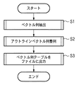
まず、ステップS1で、ベクトル列抽出処理を実行する。これは、2値画像データからベクトル列を各輪郭点に付随させて輪郭点情報込みで抽出する。そして、各ベクトルの始点の座標及びこのベクトルに流入してくる(このベクトルの始点の座標が終点となっている)ベクトル、流出してゆく(このベクトルの終点の座標が始点となっている)ベクトルを、図31B及び図31Cに示すテーブル形式で出力する。 First, in step S1, a vector string extraction process is executed. In this method, a vector sequence is extracted from binary image data with contour point information attached to each contour point. Then, the coordinates of the start point of each vector and the vector that flows into this vector (the coordinate of the start point of this vector is the end point) and flows out (the coordinate of the end point of this vector is the start point) The vectors are output in the table format shown in FIGS. 31B and 31C.
次に、ステップS2で、図31B及び図31Cに示すテーブルから流入及び流出ベクトルの項目番号を辿る。これにより、図32に示すような画像中の総輪郭線数、各輪郭線毎の輪郭線の総点数、輪郭線中の各点のx座標、y座標と各点の輪郭点情報の組み合わせを記憶したベクトル列テーブル3201を作成する。 Next, in step S2, the item numbers of the inflow and outflow vectors are traced from the tables shown in FIGS. 31B and 31C. Thereby, the total number of contour lines in the image as shown in FIG. 32, the total number of contour lines for each contour line, the x coordinate of each point in the contour line, the combination of the y coordinate and the contour point information of each point. A stored vector sequence table 3201 is created.
次に、ステップS3で、ディスクI/O521を介して、このベクトル列テーブル3201の情報をファイル形式で、ハードディスク装置522に記憶して、一連の動作を終了する。つまり、このファイルによって、画像中の領域別のベクトルデータが構成される。
Next, in step S3, the information in the vector sequence table 3201 is stored in the
次に、図31AのステップS1のベクトル列抽出処理の詳細について、図33を用いて説明する。 Next, details of the vector string extraction processing in step S1 of FIG. 31A will be described using FIG.
図33は本発明の実施形態1の図31AのステップS1のベクトル列抽出処理の詳細を示すフローチャートである。 FIG. 33 is a flowchart showing details of the vector string extraction processing in step S1 of FIG. 31A according to the first embodiment of the present invention.
まず、ステップS110で、注目画素が白画素か黒画素かを判定する。白画素の場合(ステップS110でYES)、ステップS130へ進む。一方、黒画素の場合(ステップS110でNO)、ステップS120へ進む。 First, in step S110, it is determined whether the target pixel is a white pixel or a black pixel. If it is a white pixel (YES in step S110), the process proceeds to step S130. On the other hand, in the case of a black pixel (NO in step S110), the process proceeds to step S120.
ステップS120で、注目画素の周囲8画素の状態を見て、その状態に応じた処理を実行する。 In step S120, the state of 8 pixels around the target pixel is observed, and processing corresponding to the state is executed.
ステップS130で、画素位置を更新する。そして、ステップS140で、最終画素の処理が終了したか否かを判定する。終了していない場合(ステップS140でNO)、ステップS110へ戻り、次の注目画素も同様に処理を行う。一方、終了している場合(ステップS140でYES)、元のルーチンにリターンする。 In step S130, the pixel position is updated. In step S140, it is determined whether or not the processing of the last pixel has been completed. If not completed (NO in step S140), the process returns to step S110, and the next target pixel is similarly processed. On the other hand, if it has been completed (YES in step S140), the process returns to the original routine.
ここで、ステップS1のベクトル列抽出処理の具体例として、図12に示す状態(ケース(case)0)を処理する場合を説明する。ここで、注目画素(図12の中心画素)の座標は、(2i,2j)であるとする。 Here, as a specific example of the vector sequence extraction process in step S1, a case where the state (case 0) shown in FIG. 12 is processed will be described. Here, it is assumed that the coordinates of the target pixel (center pixel in FIG. 12) are (2i, 2j).
まず、(2i−1,2j−1)を水平ベクトルの始点として登録する。即ち、図31Bの水平ベクトルカウンタ1230が示す水平ベクトル始点のx座標テーブルの欄(図31Bの1231)に(2i−1)を格納し、同じく水平ベクトル始点y座標テーブルの欄(図31Bの1232)に(2j−1)を格納する。そして、この水平ベクトルに流入してくる元の垂直ベクトルは、図31Cの垂直ベクトルカウンタ1240が、この時点で指している垂直ベクトルの始点座標テーブル内の位置の次の位置に格納されるベクトルである。また、この水平ベクトルが流出していく先の垂直ベクトルは、この時点で垂直ベクトルカウンタ1240が指している垂直ベクトルの始点座標テーブルの位置にある。
First, (2i-1, 2j-1) is registered as the start point of the horizontal vector. That is, (2i-1) is stored in the x-coordinate table column (1231 in Fig. 31B) of the horizontal vector start point indicated by the
即ち、図31Bに示す水平ベクトルの流入ベクトル項目番号の欄において、水平ベクトルカウンタ1230が示す位置(図31Bの例では、1233)に、垂直ベクトルカウンタ1240の値に1加えた値を格納する。また、水平ベクトルの流出ベクトル項目番号の欄には、水平ベクトルカウンタ1230が示す位置(図31Bの例では、1234)に、垂直ベクトルカウンタ1240の値を格納する。
That is, in the column of the inflow vector item number of the horizontal vector shown in FIG. 31B, a value obtained by adding 1 to the value of the
次に、同様に、(2i+1,2j−1)を垂直ベクトルの始点として登録する。この垂直ベクトルに流入する水平ベクトルは、1回目に登録した水平ベクトルであると登録する。また、この垂直ベクトルが流出する水平ベクトルは、水平ベクトルの始点座標テーブルの1回目に登録された水平ベクトルの次の位置に格納される水平ベクトルであると登録する。 Next, similarly, (2i + 1, 2j-1) is registered as the start point of the vertical vector. The horizontal vector flowing into this vertical vector is registered as the horizontal vector registered for the first time. Also, the horizontal vector from which this vertical vector flows out is registered as the horizontal vector stored at the next position of the horizontal vector registered for the first time in the horizontal vector start point coordinate table.
即ち、図31Cを参照して説明すると、欄241には(2i+1)が、欄242には(2i−1)が、更に、欄243には、この時の水平ベクトルカウンタ1230の値が、欄243にはこの時の水平ベクトルカウンタ1230の値に+1した値が格納される。
That is, with reference to FIG. 31C, the column 241 contains (2i + 1), the column 242 contains (2i-1), and the column 243 shows the value of the
次に、水平ベクトルカウンタ1230の内容を+1する。次に、(2i+1,2j+1)を水平ベクトルの始点座標として登録し、この水平ベクトルに流入する垂直ベクトルは、2回目に登録したベクトルであると登録する。また、この水平ベクトルが流出する垂直ベクトルは、2回目に登録された垂直ベクトルの始点座標テーブル内における次の位置に格納される垂直ベクトルであると登録する。
Next, the content of the
次に、垂直ベクトルカウンタ1240の内容を+1する。次に、(2i−1,2j+1)を垂直ベクトルの始点座標として登録し、この垂直ベクトルに流入する水平ベクトルは、3回目に登録された水平ベクトルであると登録する。また、この垂直ベクトルが流出する水平ベクトルは、1回目で登録した水平ベクトルであると登録する。こうして最後に、水平ベクトルカウンタ1230及び垂直ベクトルカウンタ1240を共に+1して処理を終了する。
Next, the content of the
次に、図33のステップS120の処理の詳細について、図34を用いて説明する。 Next, details of the processing in step S120 in FIG. 33 will be described with reference to FIG.
図34は本発明の実施形態1のステップS120の処理の詳細を示すフローチャートである。 FIG. 34 is a flowchart showing details of the process in step S120 according to the first embodiment of the present invention.
ステップS210で、CPU519のレジスタを「0」にクリアする。次に、ステップS22で、図11の「0」で示された位置の画素の状態(以下、f(0)で表現する)が黒画素(以降、「1」で表わす)であるか否かを判定する。つまり、f(0)=1であるか否かを判定する。f(0)=1である場合(ステップS220でYES)、ステップS230へ進み、レジスタの内容に1を加える。一方、f(0)=0、即ち、白画素(以降、「0」で表わす)である場合、ステップS240へ進む。
In step S210, the
次に、ステップS240で、図11の「1」の位置の画素の状態が黒画素であるか否かを判定する。つまり、f(1)=1であるか否かを判定する。f(1)=1である場合(ステップS240でYES)、ステップS250へ進み、レジスタの内容に2を加える。一方、f(1)=0である場合(ステップS240でNO)、ステップS260に進む。 Next, in step S240, it is determined whether or not the state of the pixel at the position “1” in FIG. 11 is a black pixel. That is, it is determined whether f (1) = 1. If f (1) = 1 (YES in step S240), the process proceeds to step S250, and 2 is added to the contents of the register. On the other hand, if f (1) = 0 (NO in step S240), the process proceeds to step S260.
次に、ステップS260で、図11の「2」の位置の画素の状態が黒画素であるか否かを判定する。つまり、f(2)=1であるか否かを判定する。f(2)=1である場合(ステップS260でYES)、ステップS270へ進み、レジスタの内容に4を加える。一方、f(2)=0である場合(ステップS260でNO)、ステップS280に進む。 Next, in step S260, it is determined whether or not the state of the pixel at the position “2” in FIG. 11 is a black pixel. That is, it is determined whether f (2) = 1. If f (2) = 1 (YES in step S260), the process proceeds to step S270, and 4 is added to the contents of the register. On the other hand, if f (2) = 0 (NO in step S260), the process proceeds to step S280.
次に、ステップS280で、図11の「3」の位置の画素の状態が黒画素であるか否かを判定する。つまり、f(3)=1であるか否かを判定する。f(3)=1である場合(ステップS280でYES)、ステップS290へ進み、レジスタの内容に8を加える。一方、f(3)=0である場合(ステップS280でNO)、ステップS300に進む。 Next, in step S280, it is determined whether or not the state of the pixel at position “3” in FIG. 11 is a black pixel. That is, it is determined whether f (3) = 1. If f (3) = 1 (YES in step S280), the flow advances to step S290 to add 8 to the contents of the register. On the other hand, if f (3) = 0 (NO in step S280), the process proceeds to step S300.
ステップS300で、レジスタの保持する値(処理番号)に応じた処理を実行する。 In step S300, processing corresponding to the value (processing number) held in the register is executed.
これにより、レジスタの内容は、図11に示した「0」、「1」、「2」、「3」の画素位置の各画素の状態に応じて、0〜15の値を取り得る。これらは、その値に応じてそれぞれ図12の(ケース(case)0)〜図27(ケース15)に示されている。 Thereby, the contents of the register can take values of 0 to 15 depending on the state of each pixel at the pixel positions “0”, “1”, “2”, and “3” shown in FIG. These are shown in FIG. 12 (Case 0) to FIG. 27 (Case 15) according to the values, respectively.
即ち、ステップS300で、図12〜図27に示されるように定義された輪郭点とその輪郭点情報とをそれぞれのケースに応じて抽出する。 That is, in step S300, the contour points defined as shown in FIGS. 12 to 27 and the contour point information are extracted according to each case.
このように、端点間毎輪郭(周回)ベクトル抽出部3110は、1回のラスタ走査を行なう。これにより、入力される4−連結に細線化された2値画像(線図形)から、それらを構成する端点や交点間をつなぐ独立した線や閉曲線毎に対応するベクトル列の集まり(「端点間毎線素粗輪郭ベクトル」)とその輪郭点情報を抽出し、その処理結果を出力する。
As described above, the contour (circulation)
これらは、例えば、図32に示す形式として出力される。同図における第一輪郭や第二輪郭、第a輪郭といったまとまりとして各線素から抽出されたベクトル列を示し、それらの各輪郭点毎に輪郭点情報が付与された形式となっている。 These are output, for example, in the format shown in FIG. The vector sequence extracted from each line element is shown as a group such as the first contour, the second contour, and the a-th contour in the figure, and the contour point information is given to each contour point.
ここで、図35に線図形の入力例と、これから抽出される端点間毎輪郭(周回)ベクトル、即ち、端点間毎線素粗輪郭ベクトル(太めに表現されたベクトル列)と輪郭点情報を示す。 Here, FIG. 35 shows an input example of a line figure, and a contour (circumference) vector between end points extracted from this, that is, a line element rough contour vector between end points (vector sequence expressed thickly) and contour point information. Show.
次に、端点間毎線芯(周回)ベクトル生成部3120の動作を、図36を用いて説明する。
Next, the operation of the endpoint-to-endpoint core (circumference)
図36は本発明の実施形態1の端点間毎線芯(周回)ベクトル生成部の動作を示すフローチャートである。 FIG. 36 is a flowchart showing the operation of the end-to-endpoint core line (circulation) vector generation unit according to the first embodiment of the present invention.
尚、この処理は、画像処理装置のCPU519の制御によって実現される。
This process is realized by the control of the
まず、ステップS1000で、端点間毎輪郭(周回)ベクトル抽出部3110より端点間毎輪郭(周回)ベクトルを入力する。ここで、端点間毎輪郭(周回)ベクトルは、線図形の端点(交点)位置に対応する部分から抽出されたものか否か等を表す情報(付与情報)を含む、端点や交点間をつなぐ独立した線や閉曲線毎のそれぞれに対応したベクトル列の集まりである。このベクトル列の集まりは、端点間毎線素粗輪郭ベクトルである。
First, in step S1000, an end-to-endpoint contour (circumference)
次に、ステップS1100で、ステップS1000で入力した図32に示す形式の端点間毎輪郭(周回)ベクトル群から、その中に含まれる1つのベクトル列(図32の第k輪郭(1≦k≦a))を当面の処理対象として入力する。ここでは、ステップS1100が実行されるたびに順次昇順に定める。 Next, in step S1100, from the contour (circumference) vector group between end points in the format shown in FIG. 32 input in step S1000, one vector sequence (k-th contour (1 ≦ k ≦ in FIG. 32) included therein is included. a)) is input as the current processing target. Here, every time step S1100 is executed, the order is determined in ascending order.
次に、ステップS1200で、ステップS1100で定めたベクトル列(総点数pとする)の中の1つのベクトルの輪郭点(第q点(1≦q≦p))を当面の処理対象としてm1つのベクトルを入力する。ここでは、ステップS1200が実行されるたびに順次昇順に定める。 Next, in step S1200, m1 items are processed with the contour point (qth point (1 ≦ q ≦ p)) of one vector in the vector sequence (the total number of points p) defined in step S1100 as the current processing target. Enter a vector. Here, the order is determined in ascending order every time step S1200 is executed.
次に、ステップS1300で、ステップS1200で定めた輪郭点の輪郭点情報を参照して、この輪郭点を終点とするベクトルか、もしくは、この輪郭点を始点とするベクトルのいずれかが左向き(LEFT)か否かを判定する。左向きである場合(ステップS1300でYES)、ステップS1400に進む。一方、左向きではない場合(ステップS1300でNO)、ステップS1500に進む。 Next, in step S1300, referring to the contour point information of the contour point determined in step S1200, either the vector having the contour point as the end point or the vector having the contour point as the starting point is directed to the left (LEFT ) Or not. If it is facing left (YES in step S1300), the process proceeds to step S1400. On the other hand, if it is not leftward (NO in step S1300), the process proceeds to step S1500.
ステップS1400で、輪郭点(座標値(x,y)=(2*i,2*j)とする)のy座標値を1減じて(副走査方向に半画素分原点側にずらして)、つまり、y=2*i−1を実行して、ステップS1600に進む。 In step S1400, the y coordinate value of the contour point (coordinate values (x, y) = (2 * i, 2 * j)) is reduced by 1 (shifted to the origin side by half a pixel in the sub-scanning direction), and That is, y = 2 * i−1 is executed, and the process proceeds to step S1600.
ステップS1500で、輪郭点のy座標値を1増やして(副走査方向に半画素分原点とは反対側にずらして)、つまり、y=2*i+1を実行して、ステップS1600に進む。 In step S1500, the y coordinate value of the contour point is incremented by 1 (shifted to the opposite side from the origin by half a pixel in the sub-scanning direction), that is, y = 2 * i + 1 is executed, and the flow proceeds to step S1600.
ステップS1600で、輪郭点の輪郭点情報を参照して、この輪郭点を終点とするベクトルか、もしくは、この輪郭点を始点とするベクトルのいずれかが上向き(UP)か否かを判定する。上向きである場合(ステップS1600でYES)、ステップS1700に進む。一方、上向きでない場合(ステップS1600でNO)、ステップS1800に進む。 In step S1600, referring to the contour point information of the contour point, it is determined whether either the vector having the contour point as the end point or the vector having the contour point as the starting point is upward (UP). If it is upward (YES in step S1600), the process advances to step S1700. On the other hand, if not upward (NO in step S1600), the process advances to step S1800.
ステップS1700で、輪郭点のx座標値を1増やして(主走査方向に半画素分原点とは反対側にずらして)、つまり、x=2*i+1を実行して、ステップS1900に進む。 In step S1700, the x coordinate value of the contour point is increased by 1 (shifted to the opposite side from the origin by half a pixel in the main scanning direction), that is, x = 2 * i + 1 is executed, and the flow proceeds to step S1900.
ステップS1800で、輪郭点のx座標値を1減じて(主走査方向に半画素分原点側にずらして)、つまり、x=2*i−1を実行して、ステップS1900に進む。 In step S1800, the x coordinate value of the contour point is decremented by 1 (shifted to the origin side by a half pixel in the main scanning direction), that is, x = 2 * i−1 is executed, and the flow proceeds to step S1900.
ステップS1900で、ステップS1100で定めたベクトル列内の全ての輪郭点に対する処理が終了したか否かを判定する。終了している場合(ステップS1900でNO)、ステップS2000へ進む。一方、終了していない場合(ステップS1900でYES)、同ベクトル列内の次の輪郭点に、ステップS1300からステップS1900までの処理を施すべくステップS1200にもどる。 In step S1900, it is determined whether or not processing for all contour points in the vector sequence determined in step S1100 has been completed. If completed (NO in step S1900), the process advances to step S2000. On the other hand, if not completed (YES in step S1900), the process returns to step S1200 to perform the processing from step S1300 to step S1900 on the next contour point in the vector sequence.
ステップS2000で、ステップS1000で入力した端点間毎線素粗輪郭ベクトル中の全てのベクトル列の処理が終了したか否かを判定する。終了している場合(ステップS1900でYES)、ステップS2100へ進む。一方、終了していない場合(ステップS1900でNO)、次のベクトル列に対して、ステップS1200からステップS2000までの処理を施すべくステップS1100へ戻る。 In step S2000, it is determined whether or not processing of all vector sequences in the end-to-end line element rough contour vector input in step S1000 has been completed. If completed (YES in step S1900), the process advances to step S2100. On the other hand, if not completed (NO in step S1900), the process returns to step S1100 to perform the processing from step S1200 to step S2000 on the next vector sequence.
ステップS2100で、ステップS1000で入力した端点間毎線素粗輪郭ベクトルに対する処理結果を出力する。 In step S2100, the processing result for the end-to-end line element rough contour vector input in step S1000 is output.
尚、ステップS1300やステップS1600での判定は、上述の図28における「値」欄の数値を輪郭点情報としている。そのため、これらの数値を2進数で表現した際のLSBをbit0、MSBをbit7とすると、ステップ1300ではbit2(図28では「右向(0)左向(1)」欄)を調べて、0なら右向き、1なら左向きと判定することができる。ステップS1600では、bit3(図28では「上向(0)下向(1)」欄)を調べて、0なら上向き、1なら下向きと判定することができる。 Note that the determination in step S1300 or step S1600 uses the numerical value in the “value” column in FIG. 28 as contour point information. Therefore, when these numerical values are expressed in binary, the LSB is bit0, and the MSB is bit7. In step 1300, bit2 ("right (0) leftward (1)" column in FIG. 28) is checked and 0 is obtained. If it is, it can be determined to be rightward and if it is 1, it can be determined to be leftward. In step S1600, bit 3 (in the “upward (0) downward (1)” column in FIG. 28) field is examined, and it can be determined that 0 is upward and 1 is downward.
このようにして、端点間毎輪郭(周回)ベクトル抽出部3110から端点間毎輪郭(周回)ベクトルを入力する。そして、それに含まれる付与情報を利用して、一画素幅の幅を持った輪郭(周回)ベクトルの各ベクトルの位置を、それぞれ半画素分ずつ相応する方向へ予め定める規則により微調整する。これにより、幅0に線芯化された端点間毎線芯(周回)化済ベクトルとする。これらは、端点間毎線芯(周回)化済ベクトルもまた、例えば、図32に示す形式として表現でき、実施形態1では、この形式で出力されるものとする。
In this way, the contour (circumference) vector between end points is input from the contour (circumference)
ここで、上述の図35に、端点間毎線素粗輪郭ベクトル(太めに表現されたベクトル列)と輪郭点情報から幅0に線芯化された端点間毎線芯(周回)化済ベクトル(入力2値画像の画素上の位置に細めに描かれたベクトル列)の例を示す。
Here, in FIG. 35 described above, the inter-endpoint line-core rough contour vector (the vector sequence expressed thickly) and the end-point-to-endpoint line-core (circumference) -completed vector that has been converted to a
次に、端点間毎補助ベクトル入り(周回)ベクトル生成部3210の動作を説明する。 Next, the operation of the inter-endpoint auxiliary vector-containing (circular) vector generation unit 3210 will be described.
端点間毎補助ベクトル入り(周回)ベクトル生成部3210は、次工程である端点間毎補助ベクトル入り(周回)ベクトル平滑部3220により平滑化(関数近似)処理される際に、補助ベクトルを挿入する。具体的には、端点部分に相当するベクトルが、他のベクトルと統合されて端点位置が不明にならぬように、その端点部分に相当する部分が端点として保存される(ベジェ曲線のアンカーポイントとなる)ように補助ベクトルを挿入する。
The inter-endpoint auxiliary vector-containing (circumference) vector generation unit 3210 inserts an auxiliary vector when the next-step inter-endpoint auxiliary vector-containing (circumference)
加えて、次々工程である端点間毎平滑化済ベクトル同定(非周回化)部3230で、端点間毎補助ベクトル入り(周回)ベクトル平滑部3220から得る平滑化(関数近似)済端点間毎補助ベクトル入り(周回)ベクトルから、始端点・終端点情報をも生成する。具体的には、各平滑化済の(周回)ベクトル毎にそれぞれの始端点と終端点となるベクトルを同定して、始端点と終端点の間のみの部分の非周回型のベクトル列を生成するために用いられる、各平滑化済の(周回)ベクトル毎の始端点・終端点情報をも生成する。
In addition, the smoothed (function approximation) end-to-end assistance obtained from the inter-endpoint auxiliary vector-added (circular)
実施形態1では、端点間毎補助ベクトル入り(周回)ベクトル平滑部3220は、特許文献5に開示される方法及び装置で構成されるものとする。このように構成することで、これまでの、必ずしも細線化されていない2値画像の輪郭(アウトライン)ベクトル用の平滑化手段を用いて、太さを意識せずに、細線のみで描かれている線画としてのベクトルの平滑化まで構成することが可能となる。
In the first embodiment, the inter-endpoint auxiliary vector-containing (circular)
特許文献5によれば、ベクトル平滑化(関数近似)の流れは、以下の如きである。まず、粗輪郭データと称して、2値のラスタ画像のデータより抽出された、水平ベクトル、垂直ベクトルが交互に並ぶ構成となる輪郭データを入力とする。そして、粗輪郭上の線分より接線線分を抽出する。抽出された接線線分よりアンカーポイントを抽出し、抽出されたアンカーポイント間の線分により構成されるグループを2次もしくは3次ベジェ曲線、及び直線をあてはめ、あるいは、ベジェ曲線近似を行い、3次もしくは2次のベジェ曲線により置き換える。
According to
ここで、アンカーポイントとして定めた点をもとに、アンカーポイント間にある輪郭点を1つのグループとして関数近似してい方法は、関数近似法としての基本的な手法である。また、アンカーポイントは、その間が、2次もしくは3次ベジェ曲線及び直線のいずれに関数近似されたとしても、アンカーポイント自体の位置(座標値)は、変化しないという特徴をもつ。 Here, based on the points determined as anchor points, the method of function approximation of contour points between anchor points as one group is a basic method as a function approximation method. In addition, the anchor point has a feature that the position (coordinate value) of the anchor point itself does not change regardless of whether it is approximated by a quadratic or cubic Bezier curve or a straight line.
そこで、端点間毎補助ベクトル入り(周回)ベクトル生成部3210では、端点間毎線芯(周回)化済ベクトルの端点のそれぞれを、一方を始端点と他方を終端点とする。また、それらがともにアンカーポイントとなるように始端点と終端点間に補助ベクトル(補助輪郭点)を挿入していく処理をする。 Therefore, the inter-endpoint auxiliary vector-added (circumference) vector generation unit 3210 uses one end point of the inter-endpoint line-by-line (circular) vector as one start point and the other as the end point. Further, an auxiliary vector (auxiliary contour point) is inserted between the start point and the end point so that both become anchor points.
特許文献5によれば、接線線分とするベクトルの抽出条件として、
(1)注目するベクトルの前後のベクトルの向きが互いに逆向きであるもの
(2)抽出済みの主接線線分に隣接し、ベクトルの長さL1がL1≧θ4を満たすもの
(3)ベクトルの長さL2がL2≧θ5を満たすもの
等の条件が開示されている。
According to
(1) The vector direction before and after the vector of interest is opposite to each other (2) The vector is adjacent to the extracted main tangent line segment and the vector length L1 satisfies L1 ≧ θ 4 (3) Vector conditions such as those of the length L2 satisfy L2 ≧ theta 5 is disclosed.
また、アンカーポイントの抽出に関して、抽出された接線線分上に新たな点を抽出し、それをアンカーポイントとする。アンカーポイントは、接線線分の端2つに対しそれぞれ抽出される。よって、1つの接線線分に対し2つのアンカーポイントが抽出されるが、その2つのアンカーポイントが一致した場合には、1つのアンカーポイントのみ抽出されることになる。 Further, regarding the extraction of the anchor point, a new point is extracted on the extracted tangent line segment, and is used as the anchor point. Anchor points are extracted for each of the two ends of the tangent line segment. Therefore, two anchor points are extracted for one tangent line segment, but when the two anchor points match, only one anchor point is extracted.
2つのアンカーポイントが抽出される場合は、アンカーポイントに挟まれた部位は自動的にオブジェクト上の直線となる。接線線分上の1つの端点に対するアンカーポイント抽出方法としては、注目する接線線分であるベクトルに隣接するベクトルが接線線分であれば、この隣接する側の端点をアンカーポイントとする等が開示されている。 When two anchor points are extracted, the part sandwiched between the anchor points automatically becomes a straight line on the object. As an anchor point extraction method for one end point on a tangent line segment, if the vector adjacent to the vector that is the target tangent line segment is a tangent line segment, the end point on the adjacent side is used as the anchor point. Has been.
そこで、端点間毎補助ベクトル入り(周回)ベクトル生成部3210は、点間毎線芯(周回)化済ベクトルの端点のそれぞれを、一方を始端点と他方を終端点とし、かつ、それらがともにアンカーポイントとなるように、補助点を挿入する。 Therefore, the inter-point-to-end auxiliary vector-added (circumference) vector generation unit 3210 sets each of the end points of the inter-point inter-core (circumference) vector as one start point and the other end point, and both Insert auxiliary points to be anchor points.
ここで、図37(a)を用いて、始端点としたい端点P0の直前に挿入する補助輪郭点P-1の挿入方法を説明する。 Here, a method of inserting the auxiliary contour point P −1 to be inserted immediately before the end point P 0 to be set as the start end point will be described with reference to FIG.
補助輪郭点P-1をこれを始点とする補助ベクトルV-1が、始端点としたい端点P0の直後の輪郭点P1を始点とするベクトルV1と逆向きになるように、補助輪郭点P-1を定める。このようにすれば、上述の特許文献5の接線線分の抽出条件の(1)から、ベクトルV0が接線線分となる。
The auxiliary contour point is such that the auxiliary vector V -1 starting from the auxiliary contour point P -1 is opposite to the vector V 1 starting from the contour point P1 immediately after the end point P 0 desired to be the starting end point. Define P -1 . In this way, the vector V 0 becomes the tangent line segment from the tangent line segment extraction condition (1) of
また、補助輪郭点P-1をこれを始点とする補助ベクトルV-1が上述の特許文献5の接線線分の抽出条件の(3)を満たすように十分な長さを持つようにする。このようにすれば、補助ベクトルV-1もまた接線線分となる。つまり、補助ベクトルV-1とベクトルV0とが共に接線線分となる。これにより、上述のアンカーポイント抽出方法の「注目する接線線分であるベクトルに隣接するベクトルが接線線分であれば、この隣接する側の端点をアンカーポイントとする」という条件から、始端点としたい端点P0をアンカーポイントにできる。
Further, the auxiliary vector V -1 starting from the auxiliary contour point P -1 is made to have a sufficient length so as to satisfy the extraction condition (3) of the tangent line segment of the above-mentioned
次に、図37(b)を用いて、終端点としたい端点Pnの直後に挿入する補助輪郭点Pn+1の挿入方法を説明する。 Next, a method for inserting the auxiliary contour point P n + 1 to be inserted immediately after the end point P n desired to be the end point will be described with reference to FIG.
補助輪郭点Pn+1をこれを終点とする補助ベクトルVnが、終端点としたい端点Pnの直前の輪郭点Pn-1を終点とするベクトルVn-2と逆向きになるように、補助輪郭点Pn+1を定める。このようにすれば、上述の特許文献5の接線線分の抽出条件の(1)から、ベクトルVn-1が接線線分となる。また、補助輪郭点Pn+1をこれを終点とする補助ベクトルVnが上述の特許文献5の接線線分の抽出条件の(3)を満たすように十分な長さを持つようにする。
The auxiliary vector V n whose end point is the auxiliary contour point P n + 1 is opposite to the vector V n-2 whose end point is the contour point P n-1 immediately before the end point P n desired to be the end point. Then, an auxiliary contour point P n + 1 is determined. By doing so, the vector V n-1 becomes the tangent line segment from the tangent line segment extraction condition (1) of
このようにすれば、補助ベクトルVnもまた接線線分となる。つまり、補助ベクトルVn-1とベクトルVnとが共に接線線分となる。これにより、上述のアンカーポイント抽出方法の「注目する接線線分であるベクトルに隣接するベクトルが接線線分であれば、この隣接する側の端点をアンカーポイントとする」という条件から、終端点としたい端点Pnをアンカーポイントにできる。 In this way, the auxiliary vector V n is also a tangent line segment. That is, the auxiliary vector V n-1 and the vector V n are both tangent segments. Thus, from the above-described anchor point extraction method, if the vector adjacent to the vector of the tangent line of interest is a tangent line segment, the end point on the adjacent side is used as the anchor point. The desired end point P n can be used as an anchor point.
このように、始端点と終端点がアンカーポイントになるように、それぞれ、始端点の直前への挿入点と終端点の直後への挿入点を定める。その後、これらの挿入点が水平ベクトルと垂直ベクトルの連続で連結され、始端点から終端点までの本来の輪郭点列と終端点の直後から始端点の直前までの挿入点をへて再び始端点につながる一連の輪郭点列を生成する。そして、この一連の輪郭点列の中で、どれが、始端点と終端点であるかを同定するための情報とを加えた始端点・終端点情報を生成する。 In this way, an insertion point immediately before the start point and an insertion point immediately after the end point are determined so that the start point and the end point become anchor points. After that, these insertion points are connected in a sequence of horizontal and vertical vectors, and the original contour point sequence from the start point to the end point and the insertion point from immediately after the end point to immediately before the start point are passed through again. A series of contour point sequences connected to is generated. Then, start point / end point information is generated by adding information for identifying which is the start point and the end point in the series of contour point sequences.
実施形態1では、輪郭点列中の始端点の座標値と終端点の座標値そのものを改めて別途生成することで、始端点・終端点情報とする。 In the first embodiment, the coordinate values of the start point and the end point in the contour point sequence are separately generated and used as the start / end point information.
次に、端点間毎補助ベクトル入り(周回)ベクトル生成部3210の動作について、図38を用いて説明する。 Next, the operation of the auxiliary vector-containing (circular) vector generation unit 3210 between end points will be described with reference to FIG.
図38は本発明の実施形態1の端点間毎補助ベクトル入り(周回)ベクトル生成部の動作を示すフローチャートである。 FIG. 38 is a flowchart illustrating the operation of the end point-to-endpoint auxiliary vector-containing (circular) vector generation unit according to the first embodiment of the present invention.
尚、この処理は、画像処理装置のCPU519の制御によって実現される。
This process is realized by the control of the
まず、ステップS3000で、端点間毎線芯(周回)ベクトル生成部3120から幅0に線芯化された端点間毎線芯(周回)化済ベクトルを入力する。
First, in step S3000, an inter-endpoint line-core (circumference) vector that has been line-aligned to a width of 0 is input from the inter-endpoint line-core (circumference)
次に、ステップS3100で、ステップS3000で入力した図32に示す形式の端点間毎線芯(周回)化済ベクトルから、その中に含まれる1つのベクトル列(図32の第k輪郭(1≦k≦a))を当面の処理対象として順に定める。 Next, in step S3100, one vector sequence (k-th contour (1 ≦ 1 in FIG. 32) is included in the inter-endpoint line-to-line core (circulation) completed vector input in step S3000. k ≦ a)) is determined in order as the current processing target.
次に、ステップS3200で、ステップS3100で定めたベクトル列(総点数pとする)の中の1つのベクトルの輪郭点(第q点(1≦q≦p))として、1つのベクトルを入力する。そして、ステップS3300で、始端点が見つかるまでの間、ステップS3200を実行するたびに、第1点から第p点までを昇順に順次1点ずつ当面の処理対象として定める。 Next, in step S3200, one vector is input as a contour point (qth point (1 ≦ q ≦ p)) of one vector in the vector sequence (the total number of points p) determined in step S3100. . Then, in step S3300, every time step S3200 is executed until the starting point is found, the first to pth points are sequentially set in the ascending order one by one in the ascending order.
次に、ステップS3300で、ステップS3200で定めた輪郭点の輪郭点情報を参照して、この輪郭点が始端点とすべきベクトルであるか否かを判定する。この輪郭点が始端点とすべきベクトルである場合(ステップS3300でYES)、ステップS3600に進む。一方、この輪郭点が始端点とすべきベクトルでない場合(ステップS3300でYES)、ステップS3400に進む。 Next, in step S3300, the contour point information of the contour point determined in step S3200 is referred to, and it is determined whether or not this contour point is a vector that should be the starting point. If this contour point is a vector that should be the starting point (YES in step S3300), the process advances to step S3600. On the other hand, if this contour point is not a vector that should be the starting point (YES in step S3300), the process advances to step S3400.
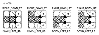
ここで、当該輪郭点が始端点とすべきベクトルであるか否かは、その輪郭点の輪郭点情報を参照して行う。具体的には、図28中のUP_RIGHT_LT(03H)、DOWN_LEFT_RB(0FH)、LEFT_UP_BL(17H)、RIGHT_DOWN_TR(1BH)のいずれかであるか否かをもってその判定を行う。これらは、図28の「値」の数値のbit1とbit0が共に1であるか否かを調べることで実現することもできる。
Here, whether or not the contour point is a vector to be the starting point is determined by referring to the contour point information of the contour point. Specifically, the determination is made based on whether or not any of UP_RIGHT_LT (03H), DOWN_LEFT_RB (0FH), LEFT_UP_BL (17H), and RIGHT_DOWN_TR (1BH) in FIG. These can also be realized by checking whether or not both the
ステップS3400で、ステップS3100で入力した端点間毎線芯(周回)化済ベクトルの中に含まれる1つのベクトル列中の全てのベクトルの処理が終了したか否かを判定する。終了していない場合(ステップS3400でNO)、当該ベクトル列中の次のベクトルに対してステップS3200の判定を施すべくステップS3200へ戻る。一方、終了している場合(ステップS3400でYES)、ステップS3100で入力したベクトル列中には、始端点候補が存在しなかった場合であり、ステップS3500へ進む。 In step S3400, it is determined whether or not processing of all vectors in one vector sequence included in the inter-endpoint line-core (circumference) completed vector input in step S3100 has been completed. If not completed (NO in step S3400), the process returns to step S3200 to make the determination in step S3200 for the next vector in the vector sequence. On the other hand, if completed (YES in step S3400), this means that the starting point candidate does not exist in the vector sequence input in step S3100, and the process advances to step S3500.
ステップS3500で、当該ベクトル列は端点のない閉ループである旨を示す閉ループマーカを該ベクトル列に対して付与した上で、それに加えて、該ベクトル列中の一連の各ベクトルをそのまま出力する。 In step S3500, a closed loop marker indicating that the vector sequence is a closed loop without end points is added to the vector sequence, and in addition, a series of vectors in the vector sequence are output as they are.
この時のデータ形式を、図39(a)に示す。同図において、対象としたベクトル列は第s番目である場合で、そのベクトル列中にはv個のベクトルが含まれている場合の例である。尚、閉ループマーカとしては、端点座標としては、本来ありえない(−1,−1)の座標値を2点分、始端点・終端点情報として付与して出力している。ステップS3500の処理を終了すると、ステップS4200へ進む。 The data format at this time is shown in FIG. In the figure, there is an example in which the target vector sequence is the s-th and v vectors are included in the vector sequence. As a closed loop marker, the coordinates of (-1, -1), which are not possible as end point coordinates, are added and output as start / end point information for two points. When the process of step S3500 ends, the process proceeds to step S4200.
一方、ステップS3600で、輪郭点を始端点として登録し、かつ、その輪郭点を始端点〜終端点間の1ベクトルとして出力して、ステップS3700へ進む。 On the other hand, in step S3600, the contour point is registered as the start point, and the contour point is output as one vector between the start point and the end point, and the flow advances to step S3700.
ステップS3700で、ステップS3200と同様に、ステップS3100で定めたベクトル列(総点数pとする)の中の1つのベクトルの輪郭点(第q点(1≦q≦p))とする。そして、ステップS3800で終端点が見つかるまでの間、ステップS3700を実行するたびにステップS3200で定められた輪郭点以降の点から第p点に向けて昇順に順次1点ずつ当面の処理対象として定め、ステップS3800に進む。 In step S3700, as in step S3200, the contour point of one vector (qth point (1 ≦ q ≦ p)) in the vector sequence (total number of points p) determined in step S3100 is set. Until the end point is found in step S3800, each time step S3700 is executed, the point is determined as an immediate processing target one by one in ascending order from the point after the contour point determined in step S3200 toward the pth point. The process proceeds to step S3800.
次に、ステップS3800で、ステップS3700で定めた輪郭点の輪郭点情報を参照して、この輪郭点が終端点とすべきベクトルであるか否かを判定する。この輪郭点が終端点とすべきベクトルである場合(ステップS3800でYES)、ステップS4000に進む。一方、この輪郭点が終端点とすべきベクトルでない場合(ステップS3800でNO)、ステップS3900に進む。 Next, in step S3800, with reference to the contour point information of the contour point determined in step S3700, it is determined whether or not this contour point is a vector to be the end point. If this contour point is a vector to be the end point (YES in step S3800), the process advances to step S4000. On the other hand, if this contour point is not a vector to be the end point (NO in step S3800), the process advances to step S3900.
ここで、当該輪郭点が終端点とすべきベクトルか否かは、その輪郭点の輪郭点情報を参照して行う。具体的には、、図28中のUP_RIGHT_TL(01H)、DOWN_LEFT_BR(0DH)、LEFT_UP_LB(15H)、RIGHT_DOWN_RT(19H)のいずれかであるか否かをもってその判定を行う。これらは、図28の「値」の数値のbit1とbit0がそれぞれ0と1であるか否かを調べることで実現することもできる。
Here, whether or not the contour point is a vector to be the end point is determined by referring to the contour point information of the contour point. Specifically, the determination is made based on whether or not one of UP_RIGHT_TL (01H), DOWN_LEFT_BR (0DH), LEFT_UP_LB (15H), and RIGHT_DOWN_RT (19H) in FIG. These can also be realized by checking whether or not the
ステップS3900で、輪郭点を始端点〜終端点間の1ベクトルとして出力して、ステップS3700へ戻る。 In step S3900, the contour point is output as one vector from the start point to the end point, and the flow returns to step S3700.
ステップS4000で、輪郭点を終端点として登録し、かつ、その輪郭点を始端点〜終端点間の1ベクトルとして出力して、ステップS4100へ進む。 In step S4000, the contour point is registered as an end point, and the contour point is output as one vector between the start point and the end point, and the flow advances to step S4100.
ステップS4100で、当該ベクトル列の始端点と終端点の両方が定まり、かつ、始端点〜終端点間の一連の各ベクトルも出力された状態となっている。ここでは、終端点〜始端点の間に挿入される一連の補助ベクトルを生成する。尚、ステップS4100の内容の詳細は、図40のフローチャートと図41及び図42を用いて追ってさらに説明を加える。ステップS4100の処理を終了すると、ステップS4200へ進む。 In step S4100, both the starting and ending points of the vector sequence are determined, and a series of vectors between the starting and ending points are also output. Here, a series of auxiliary vectors inserted between the end point and the start end point are generated. Details of step S4100 will be further described later with reference to the flowchart of FIG. 40 and FIGS. 41 and 42. When the process of step S4100 ends, the process proceeds to step S4200.
ステップS4200で、ステップS3000で入力した端点間毎線芯(周回)化済ベクトル中の全てのベクトル列の処理が終了したか否かを判定する。終了している場合(ステップS4200でYES)、ステップS4300へ進む。一方、終了していない場合(ステップS4200でNO)、次のベクトル列に対してステップS3200からステップS4200までの処理を施すべくステップS3100へ戻る。 In step S4200, it is determined whether or not the processing of all vector sequences in the inter-endpoint line-core (circumference) converted vector input in step S3000 has been completed. If completed (YES in step S4200), the process advances to step S4300. On the other hand, if not completed (NO in step S4200), the process returns to step S3100 to perform the processing from step S3200 to step S4200 on the next vector sequence.
ステップS4300で、ステップS3000で入力した端点間毎線芯(周回)化済ベクトルに対する処理結果を出力する。 In step S4300, the processing result for the end-to-endpoint core line (circulation) vector input in step S3000 is output.
図39(b)に、対象としたベクトル列に、始端点・終端点の両方が定まり、かつ、始端点〜終端点間の一連の各ベクトルと終端点〜始端点の間に挿入される一連の補助ベクトルを生成した場合に出力されるそのベクトル列に対する出力例を示す。 In FIG. 39B, both the start point and the end point are determined in the target vector sequence, and a series of vectors between the start point and the end point and a series inserted between the end point and the start point. An output example for the vector sequence output when the auxiliary vector is generated is shown.
同図において、対象としたベクトル列は第u番目である場合で、そのベクトル列中には始端点と終端点自身も含めて始端点〜終端点間の一連の各ベクトルがt個あり、かつ、終端点〜始端点の間に挿入される一連の補助ベクトルがr個ある場合の例である。ここでは、第1点は始端点そのものであり、第t点は終端点そのものとなっている。 In the figure, the target vector sequence is the u-th, and there are t series of vectors between the start point and the end point including the start point and the end point in the vector sequence, and This is an example in the case where there are r series of auxiliary vectors inserted between the terminal point and the starting point. Here, the first point is the start point itself, and the t-th point is the end point itself.
次に、図38のステップS4100の処理の詳細について、図40を用いて説明する。 Next, details of the processing in step S4100 in FIG. 38 will be described with reference to FIG.
図40は本発明の実施形態1のステップS4100の処理の詳細を示すフローチャートである。ここでは、当該ベクトル列の始端点と終端点の両方が定まり、かつ、始端点〜終端点間の一連の各ベクトルも出力された状態となっており、終端点〜始端点の間に挿入される一連の補助ベクトルを生成することが、ステップS4100の処理内容である。 FIG. 40 is a flowchart showing details of the process in step S4100 according to the first embodiment of the present invention. Here, both the starting point and the ending point of the vector sequence are determined, and a series of vectors between the starting point and the ending point are also output and inserted between the ending point and the starting point. It is the processing content of step S4100 to generate a series of auxiliary vectors.
まず、ステップS4110で、図37(a)を用いて説明したように、始端点としたい端点P0の直前に挿入する補助輪郭点P-1の座標値を算出する。即ち、補助輪郭点P-1をこれを始点とする補助ベクトルV-1が、始端点としたい端点P0の直後の輪郭点P1を始点とするベクトルV1と逆向きになるように定める。また、補助輪郭点P-1をこれを始点とする補助ベクトルV-1が、上述の特許文献5の接線線分の抽出条件の(3)を満たすように十分な長さ(例えば、10画素長以上)を持つように補助輪郭点P-1を定める。
First, in step S4110, as described with reference to FIG. 37 (a), and calculates the coordinate values of the auxiliary contour point P -1 to be inserted just before the end point P 0 to be the starting point. That is, the auxiliary vector V −1 starting from the auxiliary contour point P −1 is determined to be opposite to the vector V 1 starting from the contour point P1 immediately after the end point P 0 desired to be the starting end point. In addition, the auxiliary vector V −1 starting from the auxiliary contour point P −1 is sufficiently long (for example, 10 pixels) to satisfy the extraction condition (3) of the tangent line segment of
次に、ステップS4120で、図37(b)を用いて説明したように、終端点としたい端点Pnの直後に挿入する補助輪郭点Pn+1の座標値を算出する。即ち、補助輪郭点Pn+1をこれを終点とする補助ベクトルVnが、終端点としたい端点Pnの直前の輪郭点Pn-1を終点とするベクトルVn-2と逆向きになるように定める。また、補助輪郭点Pn+1をこれを終点とする補助ベクトルVnが、上述の特許文献5の接線線分の抽出条件の(3)を満たすように十分な長さ(例えば、10画素長以上)を持つように補助輪郭点Pn+1を定める。
Next, in step S4120, as described with reference to FIG. 37B, the coordinate value of the auxiliary contour point P n + 1 to be inserted immediately after the end point P n desired to be the end point is calculated. That is, the auxiliary vector V n whose end point is the auxiliary contour point P n + 1 is opposite to the vector V n-2 whose end point is the contour point P n-1 immediately before the end point P n desired to be the end point. Determine to be. Further, the auxiliary vector V n having the auxiliary contour point P n + 1 as an end point has a sufficient length (for example, 10 pixels) so as to satisfy the extraction condition (3) of the tangent line segment of
ステップS4130で、算出した補助輪郭点P-1を始点とする補助ベクトルV-1と、算出した補助輪郭点Pn+1を終点とする補助ベクトルVnが、共に水平ベクトルであるか否かを判定する。あるいは、共に垂直ベクトルであるか否かを判定する。いずれかの条件を満足する場合(ステップS4130でYES)、ステップS4140に進む。一方、いずれかの条件も満足しない場合(ステップS4130でNO)、ステップS4160に進む。 In step S4130, the auxiliary vector V -1 to start the auxiliary contour point P -1 calculated, auxiliary vector V n of the calculated auxiliary contour point P n + 1 to the end point is, whether both horizontal vector Determine. Alternatively, it is determined whether or not both are vertical vectors. If any condition is satisfied (YES in step S4130), the process advances to step S4140. On the other hand, if neither condition is satisfied (NO in step S4130), the process advances to step S4160.
ステップS4140での処理では、V-1とVnが、共に水平ベクトルあるいは共に垂直ベクトルである場合であり、この場合の例を図41に示す。ステップS4140では、終端点としたい端点Pnから2点目の補助輪郭点Pn+2を算出する。具体的には、PnからみてP-1から遠くなる方向に、上述の特許文献5の接線線分の抽出条件の(3)を満たすように十分な長さ(例えば、10画素長以上)を持つように補助輪郭点Pn+2を定める。
In the processing in step S4140, V −1 and V n are both horizontal vectors or both vertical vectors, and an example of this case is shown in FIG. In step S4140, the second auxiliary contour point P n + 2 is calculated from the end point P n to be the end point. Specifically, a length sufficient to satisfy the extraction condition (3) of the tangent line segment of
ステップS4150の処理も、ステップS4140と同様に、V-1とVnが、共に水平ベクトルあるいは共に垂直ベクトルである場合である。ステップS4150では、終端点としたい端点Pnから3点目の補助輪郭点Pn+3を算出する。具体的には、水平ベクトルと垂直ベクトルが交互につながる形式で、Pn+2とP-1を連結する様に、端点Pnの3点後の補助輪郭点である点Pn+3を定める。ここで、補助輪郭点Pn+3は、始端点としたい端点P0の2点前の補助輪郭点でもある。そして、一連の処理を終了すると、図38のフローチャートのステップS4200に戻る。 The processing in step S4150 is also the case where V −1 and V n are both horizontal vectors or both vertical vectors, as in step S4140. In step S4150, the third auxiliary contour point P n + 3 is calculated from the end point P n desired to be the end point. Specifically, in the form of horizontal vectors and vertical vectors connected alternately, so as to connect the P n + 2 and P -1, defines the Pn +3 points is an auxiliary contour points after three end points P n . Here, the auxiliary contour point P n + 3 is also an auxiliary contour point two points before the end point P 0 to be set as the start end point. When the series of processing is completed, the process returns to step S4200 in the flowchart of FIG.
一方、ステップS4160での処理では、V-1とVnの、どちらか一方が水平ベクトル、他方は垂直ベクトルである場合であり、この場合の例を図42に示す。ステップS4160では、終端点としたい端点Pnから2点目の補助輪郭点Pn+2を算出する。具体的には、Pn+1からみてP-1から遠くなる方向に、特許文献5の接線線分の抽出条件の(3)を満たすように十分な長さ(例えば、10画素長以上)を持つように補助輪郭点Pn+2定める。 On the other hand, in the processing in step S4160, one of V −1 and V n is a horizontal vector and the other is a vertical vector. FIG. 42 shows an example of this case. In step S4160, the second auxiliary contour point P n + 2 is calculated from the end point P n desired to be the end point. Specifically, in a direction far from P −1 as viewed from P n + 1, the length is sufficient to satisfy the extraction condition (3) of the tangent line segment of Patent Document 5 (for example, a length of 10 pixels or more). The auxiliary contour point P n + 2 is determined so as to have
ステップS4170の処理も、ステップS4160と同様に、V-1とVnが、どちらか一方が水平ベクトル、他方は垂直ベクトルである場合である。ステップS4170では、終端点としたい端点Pnから3点目の補助輪郭点Pn+3を算出する。具体的には、Pn+2からみてP-1から遠くなる方向に、特許文献5の接線線分の抽出条件の(3)を満たすように十分な長さ(例えば、10画素長以上)を持つように補助輪郭点Pn+3を定める。
Similarly to step S4160, the process of step S4170 is also a case where one of V −1 and V n is a horizontal vector and the other is a vertical vector. In step S4170, the third auxiliary contour point P n + 3 is calculated from the end point P n desired to be the end point. Specifically, a length sufficient to satisfy the extraction condition (3) of the tangent line segment of
ステップS4180の処理も、ステップS4160及びステップS4170と同様に、V-1とVnが、どちらか一方が水平ベクトル、他方は垂直ベクトルである場合である。ステップS4180では、終端点としたい端点Pnから4点目の補助輪郭点Pn+4を算出する。具体的には、水平ベクトルと垂直ベクトルが交互につながる形式で、Pn+3とP-1を連結する様に、終端点としたい端点Pnの4点後の補助輪郭点である点Pn+4を定める。ここで、補助輪郭点Pn+4は、始端点としたい端点P0の2点前の補助輪郭点でもある。そして、一連の処理が終了すると、図38のフローチャートのステップS4200に戻る。 Similar to steps S4160 and S4170, the process of step S4180 is also performed when one of V −1 and V n is a horizontal vector and the other is a vertical vector. In step S4180, the fourth auxiliary contour point P n + 4 is calculated from the end point P n desired to be the end point. Specifically, a point P which is an auxiliary contour point four points after the end point P n desired to be the end point so that P n + 3 and P −1 are connected in a form in which the horizontal vector and the vertical vector are alternately connected. Define n + 4 . Here, the auxiliary contour point P n + 4 is also an auxiliary contour point two points before the end point P 0 to be set as the start end point. When the series of processing ends, the process returns to step S4200 in the flowchart of FIG.
このようにして、端点間毎補助ベクトル入り(周回)ベクトル生成部3210は、端点間毎線芯(周回)ベクトル生成部3210より得られる端点間毎線芯(周回)化済ベクトルを入力する。そして、端点間毎補助ベクトル入り(周回)ベクトル平滑部3220で処理される際に、端点部分に相当するベクトルが、他のベクトルと統合されて端点位置が不明にならぬように補助ベクトルを挿入する。つまり、端点部分に相当する部分が端点として保存される(ベジェ曲線のアンカーポイントとなる)ように補助ベクトルを挿入することにより、端点間毎補助ベクトル入り(周回)ベクトルを生成する。
In this way, the inter-endpoint auxiliary vector-added (circumference) vector generation unit 3210 receives the inter-endpoint inter-endpoint line-by-end (circumference) vector generation vector obtained from the end-point-to-endpoint per-core (circumference) vector generation unit 3210. Then, an auxiliary vector is inserted so that the vector corresponding to the end point portion is integrated with other vectors so that the end point position is not unknown when processing is performed by the
加えて、補助ベクトルを挿入された各端点間毎補助ベクトル入り(周回)ベクトルのそれぞれに対し、どのベクトルが端点部にあたるかを明示する始端点・終端点情報をも生成する。このようにして生成された処理結果は、例えば、図32に示す形式の各輪郭データ部分のそれぞれを図39(a)や図39(b)の各ベクトル列データに置き換えた形として表現でき、実施形態1では、この形式で出力されるものとする。 In addition, start point / end point information that clearly indicates which vector corresponds to the end point portion is generated for each inter-endpoint-containing auxiliary vector (circular) vector into which the auxiliary vector is inserted. The processing result generated in this way can be expressed as, for example, a form in which each contour data portion in the format shown in FIG. 32 is replaced with each vector string data in FIG. 39 (a) and FIG. 39 (b). In the first embodiment, the data is output in this format.
尚、端点間毎補助ベクトル入り(周回)ベクトル平滑部3220は、先述のように、特許文献5に開示される方法及び装置で構成できる。その出力は、端点部分に相当する部分が端点として保存された状態で各(周回)ベクトル毎に平滑化(関数近似)された平滑化(関数近似)済端点間毎補助ベクトル入り(周回)ベクトルとして生成される。そして、次工程の処理をする端点間毎平滑化済ベクトル同定(非周回化)部3230に出力される。この際、端点間毎補助ベクトル入り(周回)ベクトル生成部3210で生成された始端点・終端点情報もそのまま次工程の処理をする端点間毎平滑化済ベクトル同定(非周回化)部3230に出力する。
In addition, the auxiliary | assistant vector containing (circular)
端点間毎平滑化済ベクトル同定(非周回化)部3230は、端点間毎補助ベクトル入り(周回)ベクトル平滑部3220より平滑化(関数近似)済端点間毎補助ベクトル入り(周回)ベクトルを入力する。また、端点間毎補助ベクトル入り(周回)ベクトル生成部3210より始端点・終端点情報を入力する。更に、各平滑化済の(周回)ベクトル列毎に、そのベクトル列内の各ベクトルの座標値を、それぞれ始端点と終端点となる輪郭点の座標値と比較していくことにより同定する。そして、始端点と終端点の間のみの部分の非周回型のベクトル列を生成して端点間毎平滑化済(非周回)ベクトルとする。そして、次工程である領域別ベクトル生成部40に出力する。
A smoothed vector identification (non-circularization) unit between
尚、生成された処理結果は、図32に示す形式に準じた形として表現することができる、但し、各輪郭点はそれまでの輪郭点情報の部分をアンカーポイントであるのか否かの属性情報としての付帯情報をもつ形をとる。ここで、同定された始端点を第1点とし、終端点が同線素ベクトルの最終点として生成することとする。 The generated processing result can be expressed as a form conforming to the format shown in FIG. 32, except that each contour point is attribute information indicating whether or not the contour point information part so far is an anchor point. It takes the form with incidental information as. Here, it is assumed that the identified start point is the first point, and the end point is generated as the final point of the same element vector.
即ち、図32の第一輪郭の部分が、第一線素のデータ部分となっており、第1点が第一線素の始端点で、第b点が第一線素の終端点となっているといった形式である。実施形態1では、このような形式で出力されるものとする。 That is, the portion of the first contour in FIG. 32 is the data portion of the first line element, the first point is the start point of the first line element, and the b-th point is the end point of the first line element. It is a form such as. In the first embodiment, it is assumed that the data is output in such a format.
このようにして、図10のフローチャートにおける、ステップS50からステップS80のループでは、交点と交点の間を繋ぐ境界線画像毎に、順次に端点間ベクトルが生成されていく。そして、全ての境界線について端点間ベクトル化の処理を終了すると、ステップS100において、領域別のベクトルを生成する領域別ベクトル生成処理を実行する。 In this manner, in the loop from step S50 to step S80 in the flowchart of FIG. 10, the inter-endpoint vectors are sequentially generated for each boundary line image connecting the intersections. When the inter-endpoint vectorization processing is completed for all the boundary lines, the region-specific vector generation processing for generating the region-specific vectors is executed in step S100.
即ち、図43に示すような交点と交点の間を繋ぐ境界線が存在するときに、図44の(a)〜(h)に示されるように、1本ずつ、順次に交点と交点の間を繋ぐ境界線画像が生成されては、端点間ベクトルが生成されて行く。 That is, when there is a boundary line connecting the intersections as shown in FIG. 43, as shown in FIGS. 44 (a) to (h), one line at a time between the intersections. When the boundary line image connecting the two is generated, the inter-endpoint vector is generated.
図45は、全ての境界線について端点間ベクトル化の処理を終了したものを、画像として再描画した形で模式的に示したものである。図46は、図45に画像として再描画した形で模式的に示した端点間毎平滑化済(非周回)ベクトルの全てを其々のベクトルの端点部を其々の元になった交点と交点の間を繋ぐ境界線画像の各交点を明示した形で画像として再描画し模式的に示したものである。 FIG. 45 schematically shows an image obtained by redrawing an end point vectorization process for all the boundary lines as an image. FIG. 46 shows all the smoothed (non-circular) vectors between the end points shown schematically in the form redrawn as an image in FIG. 45, and the intersections based on the end points of the respective vectors. The image is redrawn and schematically shown as an image in which each intersection of the boundary line image connecting the intersections is clearly shown.
ステップS30で抽出された交点やステップS50で生成された交点と交点の間を繋ぐ境界線画像の各交点は、ステップS50〜ステップS80の処理を終了しても、端点間毎平滑化済(非周回)ベクトルの各端点としてその位置と位置関係が保たれている。この意味で、ステップS30で抽出された交点は、ステップS50〜ステップS80の処理においては、端点として踏襲されて処理が進められていく。 Each intersection of the boundary line image connecting the intersections extracted at step S30 or the intersections generated at step S50 is smoothed between the end points even after the processing of step S50 to step S80 is finished (non- The position and the positional relationship are maintained as the end points of the (circular) vector. In this sense, the intersection extracted in step S30 is followed as an end point in the processing in steps S50 to S80, and the process proceeds.
ステップS100で、領域別ベクトル生成部40の処理内容(領域別ベクトル生成処理)を実行する。即ち、端点間ベクトル情報と領域分割処理によって得られる各領域の色情報に基づき、各領域にそれを取り囲む関数近似(平滑化)済端点間ベクトル列とその内部色とでなる領域ベクトルに変換する。 In step S100, the processing contents of the region-specific vector generation unit 40 (region-specific vector generation processing) are executed. That is, based on the inter-endpoint vector information and the color information of each area obtained by the area dividing process, the function is converted into an area vector composed of a function-approximate (smoothed) end-point vector sequence surrounding each area and its internal color. .
上述のように、領域別ベクトル生成部40は、領域境界ベクトル列同定部410と領域属性付与部420とで構成することが可能である。
As described above, the region-specific
ここで、ステップS100の領域別ベクトル生成処理の詳細について、図47を用いて説明する。 Details of the region-specific vector generation processing in step S100 will be described with reference to FIG.
図47は本発明の実施形態1の図10のステップS100の領域別ベクトル生成処理の詳細を示すフローチャートである。 FIG. 47 is a flowchart showing details of the region-specific vector generation processing in step S100 of FIG. 10 according to the first embodiment of the present invention.
まず、ステップS1010で、注目領域番号を入力する。即ち、ステップS12で得られた各領域の中のいずれか1つの領域の領域番号を入力する。これは、例えば、ステップS13で、RAM520上に生成された、図2に示す各領域の領域番号とそれら各領域の色情報(属性情報)の領域テーブル201を参照して、各領域の領域番号を入力する。
First, in step S1010, an attention area number is input. That is, the area number of any one of the areas obtained in step S12 is input. For example, the area number of each area is created by referring to the area table 201 of the area numbers and color information (attribute information) of each area shown in FIG. 2 generated on the
次に、ステップS1020で、ステップS1010で入力した領域番号に関連する交点(端点:注目領域関連交点)を、ステップS31で生成した図6の交点テーブル601を参照して入力する。例えば、ステップS1010で入力した領域番号が2の場合は、図6の交点テーブル601中の隣接領域番号欄に領域番号2を含む交点は、C:(22,40)、E:(38,40)、F:(44,24)の3点となる。
Next, in step S1020, an intersection point (end point: attention area-related intersection point) related to the region number input in step S1010 is input with reference to the intersection table 601 of FIG. 6 generated in step S31. For example, when the region number input in step S1010 is 2, the intersection points including the
次に、ステップS1030で、ステップS70で生成した端点間毎補助ベクトル入り(周回)ベクトルの内、ステップS1020で入力した交点を端点とするベクトル(領域境界ベクトル)を同定する。これは、図32に示す形式に準じた形としてのベクトルデータの始端点を表す第1点と終端点を表す最終点との組み合わせが、ステップS1020で抽出した交点の座標値と一致するものを選出することで実現することができる。 Next, in step S1030, a vector (region boundary vector) having the intersection point input in step S1020 as an end point among the auxiliary point-containing (circular) vectors generated in step S70 is identified. This is because the combination of the first point representing the start point and the last point representing the end point of the vector data in a form conforming to the format shown in FIG. 32 matches the coordinate value of the intersection extracted in step S1020. It can be realized by selecting.
図6の交点テーブル601のデータの場合には、図46で表現されたベクトルデータの中で、3本の関数近似(平滑化)済端点間ベクトルが、注目領域及び領域境界ベクトル列として同定される。具体的には、1つ目は、FとCを結ぶベクトル(図43の(1)から得られる関数近似(平滑化)済端点間ベクトル)である。2つ目は、CとEを結ぶベクトル(図43の(2)から得られる関数近似(平滑化)済端点間ベクトル)である。3つ目は、EとFを結ぶベクトル(図43の(3)から得られる関数近似(平滑化)済端点間ベクトル)である。 In the case of the data in the intersection table 601 in FIG. 6, among the vector data represented in FIG. 46, three function approximated (smoothed) end point vectors are identified as the attention area and the area boundary vector sequence. The Specifically, the first is a vector connecting F and C (function approximation (smoothed) inter-endpoint vector obtained from (1) in FIG. 43). The second is a vector connecting C and E (function approximation (smoothed) end-point vector obtained from (2) in FIG. 43). The third is a vector connecting E and F (function approximation (smoothed) end-point vector obtained from (3) in FIG. 43).
次に、ステップS1040で、ステップS1030で同定した注目領域の領域境界ベクトル列に対して、対応する領域の色情報(属性情報)を付与する。この処理は、RAM520上に生成された、図2に示す各領域の領域番号とそれら各領域の色情報(属性情報)の領域テーブル201を参照する。そして、この参照により、ステップS1010で入力した領域番号に相当する領域の色情報(属性情報)を獲得して、その属性情報を注目領域の領域境界ベクトル列に対して付与することで実現される。
Next, in step S1040, color information (attribute information) of the corresponding region is assigned to the region boundary vector sequence of the region of interest identified in step S1030. This process refers to the area table 201 of area numbers and color information (attribute information) of each area shown in FIG. 2 generated on the
次に、ステップS1050で、全ての領域番号に対してステップS1010〜ステップS1040の処理が終了したか否かを判定する。終了していない場合(ステップS1050でNO)、ステップS1010に戻る。一方、終了している場合(ステップS1050でYES)、図10のフローチャートのステップS100の領域別ベクトル生成処理を終了する。 Next, in step S1050, it is determined whether or not the processing in steps S1010 to S1040 has been completed for all region numbers. If not completed (NO in step S1050), the process returns to step S1010. On the other hand, if the processing has been completed (YES in step S1050), the region-specific vector generation processing in step S100 of the flowchart of FIG.
尚、ステップS1050の判定は、例えば、図2の領域テーブル201における全ての領域番号に対する処理を終了したか否か(領域テーブル201の先頭から処理を始め、最後のデータまで処理をすすめたか否か)で判定可能である。 Note that the determination in step S1050 is, for example, whether or not the processing for all region numbers in the region table 201 in FIG. ).
このようにして、実施形態1における、カラー画像、とりわけ、イラスト画像のベクトル化の一連の流れが構成される。 In this way, a series of flow of vectorization of color images, especially illustration images in the first embodiment is configured.
ここで、図48は、ステップS100で得られる、各領域毎にそれを取り囲む関数近似(平滑化)済端点間ベクトル列とその内部色とでなる領域ベクトルを、これらを画像として再生した形で模式的に示したものである。 Here, FIG. 48 shows a region vector made up of a function approximation (smoothed) end-point vector sequence surrounding each region obtained in step S100 and its internal color, reproduced as an image. It is shown schematically.
以下に、上記説明の途中で、後述するとした、領域分割処理、境界点抽出処理、交点抽出処理、交点抽出処理の詳細について説明する。 The details of the area division process, the boundary point extraction process, the intersection point extraction process, and the intersection point extraction process, which will be described later, will be described in the middle of the above description.
●領域分割処理
ステップS12の領域分割処理について、図49を用いて説明する。
Area Division Process The area division process in step S12 will be described with reference to FIG.
図49は本発明の実施形態1のステップS12の領域分割処理の詳細を示すフローチャートである。 FIG. 49 is a flowchart showing details of the area dividing process in step S12 according to the first embodiment of the present invention.
ステップS1201で、処理対象画像に対して、クラスタリング処理を行う。この処理では、まず、ラスタスキャンしたスタートの画素により、最初のクラスタを生成する。そして、次の画素に対して、全てのクラスタ間との乖離度を画素の特徴に基づいて算出する。乖離度が低いほど、画素とクラスタとの特徴が近いと考えられる。つまり、画素とクラスタは、同一とみなせる特徴(色)を持っていると考えられる。 In step S1201, clustering processing is performed on the processing target image. In this process, first, a first cluster is generated from the start pixel subjected to raster scanning. Then, for the next pixel, the degree of divergence from all the clusters is calculated based on the feature of the pixel. It is considered that the characteristics of the pixels and the clusters are closer as the divergence degree is lower. That is, it is considered that the pixel and the cluster have characteristics (colors) that can be regarded as the same.
ここで、ある画素iの特徴とは、その画素の画素値(Ri,Gi,Bi)である。また、あるクラスタcの特徴とは、そのクラスタに属する全ての画素の画素値の平均値(Ri,Gi,Bi)である。乖離度とは、例えば、画素iとクラスタcの特徴値間の色空間上でのユークリッド距離√{(Rc−Ri)2+(Gc−Gi)2+(Bc−Bi)2}である。 Here, the characteristic of a certain pixel i is the pixel value (Ri, Gi, Bi) of that pixel. The feature of a certain cluster c is an average value (Ri, Gi, Bi) of pixel values of all pixels belonging to the cluster. The degree of divergence is, for example, the Euclidean distance √ {(Rc−Ri) 2 + (Gc−Gi) 2 + (Bc−Bi) 2 } between the feature values of the pixel i and the cluster c.
ここでは、乖離度の計算にRGB値を用いるが、これに限定されず、他のカラー空間の情報、あるいは、カラー以外の情報を、画素の特徴量として使うことも可能である。そして、乖離度の値が最小となるクラスタ番号を記録し、この乖離度を事前に設定された閾値と比較する。閾値未満である場合は、対象画素を記録されたクラスタに属させる。閾値以上である場合は、対象画素により新たなクラスタを生成する。この処理は全ての画素の処理が終わるまで繰り返し実行する。 Here, RGB values are used for calculating the degree of divergence, but the present invention is not limited to this. Information on other color spaces or information other than color can also be used as pixel feature values. Then, the cluster number with the smallest divergence value is recorded, and the divergence degree is compared with a preset threshold value. If it is less than the threshold, the target pixel belongs to the recorded cluster. If it is equal to or greater than the threshold, a new cluster is generated with the target pixel. This process is repeated until all pixels have been processed.
次に、ステップS1202で、クラスタリング処理結果に基づき、領域統合処理を行う。この領域処理では、まず、分離したい領域数の目標値を入力する。本発明では、この目標値は、何色くらいに分離するかの目安となる。そして、現在のクラスタの数を計数し、現在のクラスタの数を領域数の目標値と比較する。現在のクラスタ数が目標値以上である場合、クラスタの統合を行う。領域統合処理では、各クラスタ間の乖離度を計算し、その中から一番乖離度の低い2つのクラスタを1つに統合する。領域統合処理は、現在のクラスタ数は目標値未満になるまで繰り返し実行する。 In step S1202, region integration processing is performed based on the clustering processing result. In this area processing, first, a target value for the number of areas to be separated is input. In the present invention, this target value is a measure of how many colors are separated. Then, the number of current clusters is counted, and the current number of clusters is compared with a target value for the number of regions. If the current number of clusters is greater than or equal to the target value, cluster integration is performed. In the area integration process, the divergence degree between the clusters is calculated, and two clusters having the lowest divergence degree are integrated into one. The area integration process is repeatedly executed until the current number of clusters becomes less than the target value.
次に、ステップS1203で、領域統合処理結果に基づき、ノイズ領域判定処理を行う。このノイズ領域判定処理では、まず、領域分割処理結果をラベリングし、そして、各ラベル領域の面積を計算する。ラベル領域の面積は、対象領域内の画素数である。ラベル領域の面積は、ある閾値未難である場合は、この領域をノイズ領域と判定する。 Next, in step S1203, a noise area determination process is performed based on the area integration process result. In this noise area determination process, first, the area division process result is labeled, and the area of each label area is calculated. The area of the label area is the number of pixels in the target area. If the area of the label area is not over a certain threshold, this area is determined as a noise area.
そして、ステップS1204で、このノイズ領域に含まれた各画素毎に、周囲に隣接する領域との乖離度を計算し、処理対象画素を一番乖離度の低い領域に属させるノイズ領域再処理を行う。ノイズ領域判定処理は、全てのラベル領域が処理済になるまで繰り返し実行する。文書画像の領域分離後のグラフィックス領域はより圧縮されて保存されるので、このノイズ領域判定処理とノイズ領域再処理は、圧縮の影響により発生したノイズへの対応策である。 Then, in step S1204, for each pixel included in the noise region, the degree of divergence from a neighboring region is calculated, and noise region reprocessing is performed to make the processing target pixel belong to the region having the lowest degree of divergence. Do. The noise area determination process is repeatedly executed until all label areas have been processed. Since the graphics region after the region separation of the document image is further compressed and stored, the noise region determination processing and the noise region reprocessing are countermeasures against noise generated by the influence of compression.
以上のようにして、カラー画像を同一とみなせる一貫した特徴(乖離度が閾値以上のもの)を有する、画像上で連結している其々の領域の集まりに分割することが可能となる。 As described above, it is possible to divide a color image into a group of regions connected on the image having consistent characteristics (the degree of divergence is equal to or greater than a threshold value) that can be regarded as the same.
●境界点抽出処理
ステップS21の水平方向境界点抽出処理とステップS23の垂直方向境界点抽出処理とステップS25の斜め方向境界点抽出処理について、図3を参照して説明する。
Boundary point extraction process The horizontal boundary point extraction process in step S21, the vertical boundary point extraction process in step S23, and the oblique boundary point extraction process in step S25 will be described with reference to FIG.
まず、領域分割の結果を上下順、水平方向(→)に走査し、水平方向の各走査線上のある領域から他の領域への切り替わりになる画素を水平方向境界点として抽出する。図3では、画像は(背景)領域1、領域2、領域3、領域4、そして、領域5に分割される例が示されている。
First, the result of area division is scanned in the vertical direction and in the horizontal direction (→), and a pixel that switches from one area to another area on each horizontal scanning line is extracted as a horizontal boundary point. FIG. 3 shows an example in which an image is divided into (background)
図3のように、画像の一番上から水平方向の走査により、第10行目のB点で領域番号は1から2に変わるので、Bを水平方向境界点として記録する。同様、下に行く内に、第14行目のAも水平境界点として記録する。第22行目のC、第38行目のE、第44行目のF、第64行目のH、I等も順番に水平方向境界点として記録する。 As shown in FIG. 3, since the region number is changed from 1 to 2 at the point B in the tenth row by scanning in the horizontal direction from the top of the image, B is recorded as a horizontal boundary point. Similarly, while going down, A in the 14th row is recorded as a horizontal boundary point. The C in the 22nd line, the E in the 38th line, the F in the 44th line, the H and I in the 64th line, etc. are recorded in order as horizontal boundary points.
そして、領域分割の結果を左右順、垂直方向(↓)に走査し、垂直方向の各走査線上のある領域から他の領域への切り替わりになる画素を垂直方向境界点として抽出する。 Then, the result of region division is scanned in the left-right order and the vertical direction (↓), and a pixel that switches from one region to another region on each scanning line in the vertical direction is extracted as a vertical boundary point.
図3のように、垂直方向の走査により、第10列目のD、第15列目のA、第20列目のB、第24列目のF、第40列目のE、C、第58列目のH、第66列目のI等も順番に垂直方向境界点として記録する。 As shown in FIG. 3, by scanning in the vertical direction, D in the 10th column, A in the 15th column, B in the 20th column, F in the 24th column, E, C in the 40th column, The 58th column H, the 66th column I, etc. are also recorded in order as vertical boundary points.
そして、領域分割の結果を上下順、斜め方向に走査し、斜め方向の各走査線上のある領域から他の領域への切り替わりになる画素を斜め方向境界点として抽出する。 Then, the result of area division is scanned in an up-down order and an oblique direction, and a pixel that switches from one area to another area on each oblique scanning line is extracted as an oblique boundary point.
図3のように、斜め方向の走査により、第14行目、第15列目のA点で領域番号は1から2に変わるので、A点を斜め方向境界点として記録する。同様に、B、J、C、K、E、G、D、H、I等も斜め方向境界点として記録する。 As shown in FIG. 3, the area number is changed from 1 to 2 at point A in the 14th row and 15th column by scanning in the oblique direction, so that point A is recorded as an oblique boundary point. Similarly, B, J, C, K, E, G, D, H, I, etc. are recorded as diagonal boundary points.
ここでは、説明を簡単にするため、以上の幾つかの境界点のみを例に用いている。図50は、B点とA点の間の境界線を拡大して、この境界線の水平方向と垂直方向と斜め方向境界点の抽出例を示す図である。 Here, in order to simplify the description, only the above-mentioned several boundary points are used as an example. FIG. 50 is a diagram illustrating an example of extracting the boundary points in the horizontal direction, the vertical direction, and the oblique direction of the boundary line by enlarging the boundary line between the points B and A.
図50(a)はAB境界線付近の画素図であり、画素(1)は領域1にある画素で、画素(2)は領域2にある画素である。
FIG. 50A is a pixel diagram in the vicinity of the AB boundary, in which pixel (1) is a pixel in
図50(b)は水平方向境界点抽出処理により、最初に水平方向に領域番号が変わった所、即ち、ハッチングパターンが付されている画素(1)は水平方向境界点として抽出された結果である。 FIG. 50B shows the result of the horizontal boundary point extraction processing where the area number first changed in the horizontal direction, that is, the pixel (1) to which the hatching pattern is attached is extracted as the horizontal boundary point. is there.
図50(c)は垂直方向境界点抽出処理により、ハッチングパターンが付されている画素(1)が垂直方向境界点として抽出された結果である。 FIG. 50C shows the result of extracting the pixel (1) with the hatching pattern as the vertical boundary point by the vertical boundary point extraction process.
図50(d)は斜め方向境界点抽出処理により、ハッチングパターンが付されている画素(1)が斜め方向境界点として抽出された結果である。 FIG. 50D shows the result of extracting the hatched pattern pixel (1) as the diagonal boundary point by the diagonal boundary point extraction process.
図50(e)は水平方向境界点抽出、垂直方向境界点抽出、及び斜め方向境界点抽出処理の少なくともいずれか1つ以上により抽出された境界点が、ハッチングパターンが付されている画素(1)で示されている。即ち、このハッチングパターンが付されている画素(1)は、図50(b)と図50(c)と図50(d)のハッチングパターンが付されている画素(1)を合わせたものとなっている。これらの境界点は、4−連結状態となっている。 FIG. 50E shows a pixel (1) where a boundary point extracted by at least one of horizontal boundary point extraction, vertical boundary point extraction, and diagonal direction boundary point extraction processing is hatched. ). That is, the pixel (1) to which this hatching pattern is attached is a combination of the pixel (1) to which the hatching pattern of FIG. 50 (b), FIG. 50 (c) and FIG. 50 (d) is attached. It has become. These boundary points are in a 4-connected state.
実施形態1における境界線画像の生成を明確にするため、さらに図51を用いて、水平方向境界点抽出処理と垂直方向境界点抽出処理と斜め方向境界点抽出処理の説明を加える。 In order to clarify the generation of the boundary line image in the first embodiment, further explanations of the horizontal boundary point extraction process, the vertical boundary point extraction process, and the oblique boundary point extraction process will be added with reference to FIG.
図51(a)は、下地領域中に四つの矩形領域からなる図の領域分割の結果である。図51(b)は、図51(a)の境界線周囲の画素をあらわすものである。 FIG. 51 (a) shows the result of region division in a diagram including four rectangular regions in the base region. FIG. 51 (b) shows pixels around the boundary line of FIG. 51 (a).
図51(c)は、図51(b)からハッチングパターンが付加された画素を水平方向境界点として抽出した水平境界点抽出処理の結果である。 FIG. 51C shows the result of the horizontal boundary point extraction process in which the pixels to which the hatching pattern is added from FIG. 51B are extracted as the horizontal direction boundary points.
図51(d)は図51(b)からハッチングパターンが付加された画素を垂直方向境界点として抽出した垂直方向境界点の結果である。 FIG. 51D shows the result of the vertical boundary point obtained by extracting the pixel to which the hatching pattern is added from FIG. 51B as the vertical boundary point.
図51(e)は図51(b)からハッチングパターンが付加された画素を斜め方向境界点として抽出した斜め方向境界点の結果である。 FIG. 51 (e) shows the result of the diagonal boundary point extracted from FIG. 51 (b) as the diagonal boundary point.
図51(f)は以上の、水平方向、垂直方向、斜め方向の少なくともいずれか1つ以上の境界点抽出処理により抽出された全ての境界点である。これらの境界点は4−連結である。 FIG. 51 (f) shows all the boundary points extracted by at least one of the boundary point extraction processes in the horizontal direction, the vertical direction, and the oblique direction. These boundary points are 4-connected.
●交点抽出処理
ステップS30の交点抽出処理について、図52を用いて説明する。
Intersection extraction process The intersection extraction process in step S30 will be described with reference to FIG.
図52は本発明の実施形態1のステップS30の交点抽出処理の詳細を示すフローチャートである。 FIG. 52 is a flowchart showing details of the intersection extraction processing in step S30 according to the first embodiment of the present invention.
ステップS301で、ステップS22、ステップS24及びステップS26それぞれで生成された水平方向境界点テーブル401、垂直方向境界点テーブル402及び斜め方向境界点テーブル403を参照する。そして、その3つのテーブル401〜403上で2つ以上のテーブルに存在する境界点の内、テーブル401〜403それぞれでの隣接する領域番号とから3つ以上の領域番号を持つ境界点を探索して、それを交点とする。 In step S301, the horizontal boundary point table 401, the vertical boundary point table 402, and the diagonal boundary point table 403 generated in steps S22, S24, and S26 are referred to. Then, among the boundary points existing in two or more tables on the three tables 401 to 403, a boundary point having three or more area numbers is searched from the adjacent area numbers in each of the tables 401 to 403. And that is the intersection.
尚、3つのテーブル上で2つ以上のテーブルに存在する境界点とは、水平境界点かつ垂直方向境界点、水平方向境界点かつ斜め方向境界点、垂直方向境界点かつ斜め方向境界点、あるいは水平方向境界点かつ垂直方向境界点かつ斜め方向境界点のいずれかである。 The boundary points existing in two or more tables on the three tables are a horizontal boundary point and a vertical boundary point, a horizontal boundary point and an oblique boundary point, a vertical boundary point and an oblique boundary point, or Any of a horizontal boundary point, a vertical boundary point, and an oblique boundary point.
図5では、図3の領域分割の結果から抽出された境界点から構成された図4の水平方向境界点テーブル401、垂直方向境界点テーブル402及び斜め方向境界点テーブル403とから交点を抽出する例が示されている。 In FIG. 5, the intersection is extracted from the horizontal boundary point table 401, the vertical boundary point table 402, and the diagonal boundary point table 403 shown in FIG. 4 that are formed from the boundary points extracted from the region division result shown in FIG. An example is shown.
境界点Cの水平方向の隣接領域番号は2、3で、垂直方向の隣接領域番号は1、2で、斜め方向の隣接領域番号は2、3であるので、C点は2つ以上の境界点テーブルに存在することが分かる。また、C点は3つ以上の隣接領域番号を持っているので、C点を交点として抽出する。 The boundary point C has a horizontal adjacent region number of 2 and 3, a vertical adjacent region number of 1 and 2, and a diagonal adjacent region number of 2 and 3, so point C has two or more boundaries. It can be seen that it exists in the point table. Further, since the point C has three or more adjacent region numbers, the point C is extracted as an intersection.
同様に、E、F、Gも交点である。そのほか、A、B、D、H、I等は水平方向の隣接領域番号と垂直方向の隣接領域番号と斜め方向の隣接領域番号が同じなので、2つの領域の間にあることが分かり、交点ではないと判断する。 Similarly, E, F, and G are intersections. In addition, since A, B, D, H, I, etc. have the same horizontal adjacent area number, vertical adjacent area number, and diagonal adjacent area number, it can be seen that they are between two areas. Judge that there is no.
図53(a)では、図51(a)の領域分割結果からの交点抽出例が示されている。図53(a)は、各方向(水平、垂直及び斜め)の境界点抽出処理それぞれにより抽出された境界点に対する、各方向の境界点テーブル作成処理により生成された各境界点テーブル401〜403である。そして、水平方向境界点テーブル401、垂直方向境界点テーブル402及び斜め方向境界点テーブル403の3つの境界点テーブル上で、少なくとも2つ以上の境界点テーブルにある境界点毎に線種別にマークしたものである。 FIG. 53 (a) shows an example of intersection intersection extraction from the region division result of FIG. 51 (a). FIG. 53A shows the boundary point tables 401 to 403 generated by the boundary point table creation process in each direction for the boundary points extracted by the boundary point extraction process in each direction (horizontal, vertical, and diagonal). is there. Then, on the three boundary point tables of the horizontal boundary point table 401, the vertical boundary point table 402, and the diagonal boundary point table 403, the line type is marked for each boundary point in at least two boundary point tables. Is.
図53(b)は図53(a)でマークされた境界点から、さらに3つ以上の互いに相異なる隣接領域番号を持つ境界点を交点として、これらを交点テーブル601としてまとめて記録した結果である。図53(c)は交点となった点を、矩形のグレーパターンで示したものである。 FIG. 53B shows the result of recording the boundary points having three or more different adjacent region numbers from the boundary points marked in FIG. 53A as intersections and collectively recording them as the intersection table 601. is there. FIG. 53 (c) shows the points at the intersections as rectangular gray patterns.
そして、ステップS302で、すべての領域番号の其々が、ステップS301で抽出された各交点の内のいずれかの交点の隣接領域番号に含まれているかどうかを判定する。全ての領域番号が含まれている場合(ステップS302でYES)、全部の領域に交点が存在していると判定し、この交点抽出処理を終了する。 In step S302, it is determined whether each of all the area numbers is included in the adjacent area number of any intersection among the intersections extracted in step S301. If all region numbers are included (YES in step S302), it is determined that intersections exist in all regions, and this intersection extraction process is terminated.
一方、いずれの交点の隣接領域番号にも含まれない領域番号がある場合(ステップS302でNO)、この領域には隣接領域が複数存在することはなく、ステップS301での処理では交点が見つからなかったと判定する。 On the other hand, when there is an area number that is not included in the adjacent area number of any intersection (NO in step S302), there is no plurality of adjacent areas in this area, and no intersection is found in the process in step S301. It is determined that
図3の例では、ステップS301で抽出された交点C、E、F、Gの隣接領域番号に1〜4の領域番号が含まれているので、領域1〜4の境界点には交点が存在する。しかし、領域番号5を隣接領域番号に含む交点は存在しないので、領域5は、他の領域との境界点に交点がない、独立した領域であると判断する。
In the example of FIG. 3, since the
ステップS303で、ステップS302で判定された交点のない領域に対し、ステップS22、ステップS24及びステップS26で生成された水平方向境界点テーブル401、垂直方向境界点テーブル402及び斜め方向境界点テーブル403を再び参照する。そして、交点のない領域番号を隣接領域番号に持つ境界点を任意に2点取り、この交点のなかった領域の交点にする。 In step S303, the horizontal boundary point table 401, the vertical boundary point table 402, and the diagonal boundary point table 403 generated in step S22, step S24, and step S26 are stored in the region having no intersection determined in step S302. Refer again. Then, two boundary points having an area number having no intersection as an adjacent area number are arbitrarily taken and set as intersections of areas having no intersection.
例えば、図4の水平方向境界点テーブル401、垂直方向境界点テーブル402及び斜め方向境界点テーブル403とから隣接領域番号5を含み、かつ、2つの隣接領域番号を持つ境界点HとIを取り、領域5の交点にする。これらは、HとIの位置に限らず、例えば、図4の水平方向境界点テーブル401、垂直方向境界点テーブル402及び斜め方向境界点テーブル403を各テーブルの先頭からサーチする。そして、最初に見つかる条件を満たす点(即ち、隣接領域番号5を含む境界点)と、同条件を満たすその他の点の中で、最初に見つかった点から最も離れた点等としても良い。
For example, from the horizontal boundary point table 401, the vertical boundary point table 402, and the diagonal boundary point table 403 in FIG. , The intersection of
以上説明したように、実施形態1によれば、画像を領域毎に分割してベクトル化する際には、画素間の特徴によって得られる乖離度に基づいて、画像を分割する。次に、これによって得られる領域に対して、隣接する領域間の境界に関する領域境界情報として、境界の交点を端点とした場合のその端点間を表現するベクトル(端点間ベクトル)の向きを示す輪郭点情報を生成する。 As described above, according to the first embodiment, when an image is divided into regions and vectorized, the image is divided based on the degree of divergence obtained by the feature between pixels. Next, for the region obtained by this, as region boundary information related to the boundary between adjacent regions, an outline indicating the direction of a vector (inter-endpoint vector) expressing the distance between the end points when the intersection of the boundaries is the end point Generate point information.
そして、この輪郭点情報に基づいて、分割された領域の境界を構成する端点間ベクトルを同定する。より具体的には、この輪郭点情報によって、各端点間ベクトルの位置関係を把握した上で、分割された領域の境界を構成する端点間ベクトルを同定する。これにより、領域を表現するベクトルデータを正確かつ適切に生成することが可能となる。つまり、従来技術のように、各領域間に隙間や重なりが生じるようなベクトルデータが生成されることを防止することができる。 Then, based on the contour point information, the inter-endpoint vectors constituting the boundaries of the divided areas are identified. More specifically, based on the contour point information, the positional relationship between the end point vectors is grasped, and the end point vectors constituting the boundaries of the divided areas are identified. This makes it possible to generate vector data representing a region accurately and appropriately. That is, it is possible to prevent generation of vector data that causes gaps or overlaps between the regions as in the conventional technique.
<実施形態2>
実施形態2では、図54に示すように、全ての境界線画像を全て含む細線画像を生成した後に、この画像から、ベクトル抽出時に交点を改めて検出しつつ、一括してベクトル化する構成をとる。この場合の処理を図55を用いて説明する。
<
In the second embodiment, as shown in FIG. 54, after a fine line image including all the boundary line images is generated, an intersection point is detected from this image at the time of vector extraction, and vectorized in a batch. . Processing in this case will be described with reference to FIG.
図55は本発明の実施形態2の画像処理装置の動作を示すフローチャートである。 FIG. 55 is a flowchart showing the operation of the image processing apparatus according to the second embodiment of the present invention.
同図において、実施形態1の図10のフローチャートと異なる部分は、次のようになっている。つまり、図10のステップS70の端点間ベクトル生成処理が、ステップS50〜ステップS80の処理ループ内にあるのに対し、図55では、ステップS50〜ステップS80の処理ループ外のステップS90の端点間ベクトル生成処理として存在する点である。即ち、図54で示すように、全ての境界線画像を全て含む細線画像を生成した後に、この画像から、ベクトル抽出時に交点を改めて検出しつつ、一括してベクトル化する構成をとっている。
In the same figure, the different part from the flowchart of FIG. 10 of
ステップS90の端点間ベクトル生成処理(実施形態1の図10におけるステップS70の端点間ベクトル生成処理と同様な処理)時においても、実施形態1で説明したように、交点部を端点として抽出する。そのため、このように構成しても、実施形態1と同様に、図45や図46に画像として再描画した形で模式的に示したような、端点間毎平滑化済(非周回)ベクトルの集まりとして生成される。 In the inter-endpoint vector generation process in step S90 (the same process as the inter-endpoint vector generation process in step S70 in FIG. 10 of the first embodiment), as described in the first embodiment, the intersection part is extracted as an end point. For this reason, even with this configuration, as in the first embodiment, the smoothed (non-circular) vector between end points as schematically shown in FIG. 45 and FIG. 46 as an image redrawn. Generated as a collection.
即ち、ステップS30で抽出された交点や、ステップS50で生成された交点と交点の間を繋ぐ境界線画像における各交点は、ステップS90の端点間ベクトル生成の処理において、端点間毎平滑化済(非周回)ベクトルの交点として同定される。そして、その交点と交点の間を繋ぐ端点間ベクトル群として一括して生成される。以降のステップS100の処理は、実施形態1の場合と全く同様である。 In other words, the intersection points extracted in step S30 and the intersection points in the boundary line image connecting the intersection points generated in step S50 are smoothed between the end points in the process of generating the end point vectors in step S90 ( Identified as the intersection of non-circular) vectors. And it produces | generates collectively as an end point vector group which connects between the intersections. The subsequent processing in step S100 is exactly the same as in the case of the first embodiment.
以上説明したように、実施形態2によれば、実施形態1で説明した効果に加えて、境界線画像を全て含む細線画像に対して、それを構成する端点間ベクトル群を生成し、それに基づいて、領域別ベクトルを生成することができる。これにより、より効率的に領域別ベクトルを生成することができる。 As described above, according to the second embodiment, in addition to the effects described in the first embodiment, a vector group between end points is generated for the fine line image including all the boundary line images, and based on that. Thus, a region-specific vector can be generated. As a result, the region-specific vectors can be generated more efficiently.
<実施形態3>
実施形態1及び2においては、ともに、入力画像の全ての分割領域をベクトル化することを前提に説明してきたが、本発明はこれに限定されるものではない。即ち、画像処理装置の通信I/F4等を経由して、あるいはポインティングデバイス(不図示)のユーザーインタフェース(以下、UIと記す)を用いて、ベクトル化対象とする分割領域を限定して、その領域のみをベクトル化するように構成してももちろん良い。
<
In both Embodiments 1 and 2, the description has been made on the assumption that all the divided regions of the input image are vectorized, but the present invention is not limited to this. That is, by limiting the divided areas to be vectorized via the communication I /
この場合、図47のフローチャートにおけるステップS1010で、図2の領域テーブル201に記載されている注目領域番号を順番に自動入力するのではなく、通信I/F4やUI等を介して、ユーザの指示に基づき、ベクトル化対象とする分割領域を指定する。そして、この指定された分割領域に限定してベクトル化(領域別ベクトルを生成)するように構成してももちろん良い。例えば、図2〜3のように5つの分割領域がある場合、ユーザが領域2、3、5を指定すると、この指定された領域2,3,5それぞれの領域別ベクトルが生成されることになる。
In this case, in step S1010 in the flowchart in FIG. 47, the attention area number described in the area table 201 in FIG. 2 is not automatically input in order, but the user's instruction is made via the communication I /
この場合の処理を図56を用いて説明する。 Processing in this case will be described with reference to FIG.
図56は本発明の実施形態3の画像処理装置の動作を示すフローチャートである。 FIG. 56 is a flowchart showing the operation of the image processing apparatus according to the third embodiment of the present invention.
図56のフローチャートに示すように、ステップS40で、上述のベクトル化対象とする分割領域を限定するためのベクトル化対象領域情報(注目領域番号)を獲得する。そして、このステップS40以外は、実施形態2の図55のフローチャートと同様である。但し、ステップS50〜ステップS100までの処理は、ステップS40で獲得したベクトル化対象領域情報が示す領域のみを、処理対象として一連の動作をする点が、実施形態3の特徴的な構成である。 As shown in the flowchart of FIG. 56, in step S40, vectorization target area information (attention area number) for limiting the above-described divided areas to be vectorized is acquired. The steps other than step S40 are the same as those in the flowchart of FIG. 55 of the second embodiment. However, the processing from step S50 to step S100 is a characteristic configuration of the third embodiment in that a series of operations are performed on only the region indicated by the vectorization target region information acquired in step S40.
以上説明したように、実施形態3によれば、実施形態1で説明した効果に加えて、画像中の注目領域を処理対象として指定することが可能になるので、その注目領域に対してのみ、その領域の領域ベクトルを生成することができる。これにより、用途や目的に応じて、より効率的に必要とする領域の領域ベクトルを生成することができる。 As described above, according to the third embodiment, in addition to the effects described in the first embodiment, it is possible to designate a region of interest in the image as a processing target. An area vector for the area can be generated. Thereby, the area vector of the area | region required more efficiently according to a use or the objective can be produced | generated.
以上、実施形態例を詳述したが、本発明は、例えば、システム、装置、方法、プログラムもしくは記憶媒体等としての実施態様をとることが可能である。具体的には、複数の機器から構成されるシステムに適用しても良いし、また、1つの機器からなる装置に適用しても良い。 Although the embodiment has been described in detail above, the present invention can take an embodiment as a system, apparatus, method, program, storage medium, or the like. Specifically, the present invention may be applied to a system composed of a plurality of devices, or may be applied to an apparatus composed of one device.
尚、本発明は、前述した実施形態の機能を実現するソフトウェアのプログラム(実施形態では図に示すフローチャートに対応したプログラム)を、システムあるいは装置に直接あるいは遠隔から供給する。そして、そのシステムあるいは装置のコンピュータが該供給されたプログラムコードを読み出して実行することによっても達成される場合を含む。 In the present invention, a software program (in the embodiment, a program corresponding to the flowchart shown in the drawing) that realizes the functions of the above-described embodiments is directly or remotely supplied to a system or apparatus. In addition, this includes a case where the system or the computer of the apparatus is also achieved by reading and executing the supplied program code.
従って、本発明の機能処理をコンピュータで実現するために、該コンピュータにインストールされるプログラムコード自体も本発明を実現するものである。つまり、本発明は、本発明の機能処理を実現するためのコンピュータプログラム自体も含まれる。 Accordingly, since the functions of the present invention are implemented by computer, the program code installed in the computer also implements the present invention. In other words, the present invention includes a computer program itself for realizing the functional processing of the present invention.
その場合、プログラムの機能を有していれば、オブジェクトコード、インタプリタにより実行されるプログラム、OSに供給するスクリプトデータ等の形態であっても良い。 In that case, as long as it has the function of a program, it may be in the form of object code, a program executed by an interpreter, script data supplied to the OS, or the like.
プログラムを供給するための記録媒体としては、例えば、フロッピー(登録商標)ディスク、ハードディスク、光ディスクがある。また、更に、記録媒体としては、光磁気ディスク、MO、CD−ROM、CD−R、CD−RW、磁気テープ、不揮発性のメモリカード、ROM、DVD(DVD−ROM,DVD−R)などがある。 Examples of the recording medium for supplying the program include a floppy (registered trademark) disk, a hard disk, and an optical disk. Further, as a recording medium, magneto-optical disk, MO, CD-ROM, CD-R, CD-RW, magnetic tape, nonvolatile memory card, ROM, DVD (DVD-ROM, DVD-R), etc. is there.
その他、プログラムの供給方法としては、クライアントコンピュータのブラウザを用いてインターネットのホームページに接続する。そして、その接続先のホームページから本発明のコンピュータプログラムそのもの、もしくは圧縮され自動インストール機能を含むファイルをハードディスク等の記録媒体にダウンロードすることによっても供給できる。また、本発明のプログラムを構成するプログラムコードを複数のファイルに分割し、それぞれのファイルを異なるホームページからダウンロードすることによっても実現可能である。つまり、本発明の機能処理をコンピュータで実現するためのプログラムファイルを複数のユーザに対してダウンロードさせるWWWサーバも、本発明に含まれるものである。 As another program supply method, a browser on a client computer is used to connect to an Internet home page. Then, the computer program itself of the present invention or a compressed file including an automatic installation function can be downloaded from a homepage of the connection destination to a recording medium such as a hard disk. It can also be realized by dividing the program code constituting the program of the present invention into a plurality of files and downloading each file from a different homepage. That is, a WWW server that allows a plurality of users to download a program file for realizing the functional processing of the present invention on a computer is also included in the present invention.
また、本発明のプログラムを暗号化してCD−ROM等の記憶媒体に格納してユーザに配布し、所定の条件をクリアしたユーザに対し、インターネットを介してホームページから暗号化を解く鍵情報をダウンロードさせる。そして、その鍵情報を使用することにより暗号化されたプログラムを実行してコンピュータにインストールさせて実現することも可能である。 In addition, the program of the present invention is encrypted, stored in a storage medium such as a CD-ROM, distributed to users, and key information for decryption is downloaded from a homepage via the Internet to users who have cleared predetermined conditions. Let It is also possible to execute the encrypted program by using the key information and install the program on a computer.
また、コンピュータが、読み出したプログラムを実行することによって、前述した実施形態の機能が実現される。また、そのプログラムの指示に基づき、コンピュータ上で稼動しているOSなどが、実際の処理の一部または全部を行ない、その処理によっても前述した実施形態の機能が実現され得る。 Further, the functions of the above-described embodiments are realized by the computer executing the read program. Further, based on the instructions of the program, an OS or the like running on the computer performs part or all of the actual processing, and the functions of the above-described embodiments can be realized by the processing.
さらに、記録媒体から読み出されたプログラムが、コンピュータに挿入された機能拡張ボードやコンピュータに接続された機能拡張ユニットに備わるメモリに書き込まれる。その後、そのプログラムの指示に基づき、その機能拡張ボードや機能拡張ユニットに備わるCPUなどが実際の処理の一部または全部を行ない、その処理によっても前述した実施形態の機能が実現される。 Further, the program read from the recording medium is written in a memory provided in a function expansion board inserted into the computer or a function expansion unit connected to the computer. Thereafter, the CPU of the function expansion board or function expansion unit performs part or all of the actual processing based on the instructions of the program, and the functions of the above-described embodiments are realized by the processing.
1 スキャナ
2 画像メモリ
3 画像入出力I/O
4 通信I/O
6 ROM
518 バス
519 CPU
520 RAM
521 I/O
522 H/D
1
4 Communication I / O
6 ROM
518
520 RAM
521 I / O
522 H / D
Claims (12)
前記画像を構成する各画素の属性情報に基づいて、前記画像を複数の領域に分割する分割手段と、
前記分割手段により分割した各領域の境界線に関する領域境界情報を抽出する抽出手段と、
前記抽出手段により抽出した領域境界情報に基づいて、前記境界線の交点を同定する交点情報生成手段と、
前記交点情報生成手段で同定した交点を端点として、前記境界線における前記端点間の部分毎に、関数近似処理を実行することにより、当該関数近似された端点間毎の境界線を示す端点間ベクトルデータを生成する端点間ベクトル生成手段と、
前記端点間ベクトル生成手段により生成した端点間ベクトルデータを用いて、前記分割手段により分割された各領域を囲む領域別のベクトルデータを生成する領域別ベクトル生成手段と
を備え、
前記端点間ベクトル生成手段で前記関数近似処理により生成される前記端点間ベクトルデータの端点の位置は、前記関数近似処理の実行前の前記端点の位置から変化しない
ことを特徴とする画像処理装置。 An image processing apparatus that executes vector processing for vectorizing an image,
Dividing means for dividing the image into a plurality of regions based on attribute information of each pixel constituting the image;
Extraction means for extracting region boundary information relating to the boundary lines of each region divided by the dividing unit;
Based on the region boundary information extracted by the extraction means, intersection information generating means for identifying the intersection of the boundary lines;
As the end point of intersection identified in the intersection information generating means for each portion between the end points of the boundary line, by performing function approximation processing, endpoint-to-endpoint vector indicating the boundaries of each among the function approximated endpoint Endpoint-to-endpoint vector generating means for generating data;
Using region-to-endpoint vector data generated by the endpoint-to-endpoint vector generating unit, and generating region-specific vector data surrounding each region divided by the dividing unit ,
The image processing apparatus according to claim 1, wherein the position of the end point of the inter-endpoint vector data generated by the function approximation process by the end point vector generation means does not change from the position of the end point before the function approximation process .
前記分割手段により分割した領域の属性情報に基づいて、前記端点間ベクトル生成手段により生成した端点間ベクトルデータから、前記分割手段により分割した各領域について当該各領域を囲む1つ以上の端点間ベクトルデータを同定する同定手段と、
前記同定手段で前記各領域について同定した端点間ベクトルデータに対して、前記各領域に対応する属性情報を付与する付与手段とを備え、
前記同定手段で前記各領域について同定した前記各領域を囲む1つ以上の端点間ベクトルデータと前記付与手段で付与した前記各領域の属性情報からなるベクトルデータを、前記領域別のベクトルデータとして生成する
ことを特徴とする請求項1に記載の画像処理装置。 The region-specific vector generation means includes:
Based on the attribute information of the area divided by the dividing means, one or more end-point vectors surrounding each area for each area divided by the dividing means from the inter-endpoint vector data generated by the inter-endpoint vector generating means An identification means for identifying the data;
An assigning unit for assigning attribute information corresponding to each region to the inter-endpoint vector data identified for each region by the identifying unit;
Generating vector data consisting of one or more end point vector data surrounding each area identified by the identification means and the attribute information of each area given by the giving means as vector data for each area The image processing apparatus according to claim 1, wherein:
ことを特徴とする請求項1又は2に記載の画像処理装置。 The image processing apparatus according to claim 1, wherein the region boundary information is information relating to a pixel located between boundaries between regions where different regions are adjacent to each other.
ことを特徴とする請求項1乃至3のいずれか1項に記載の画像処理装置。 The intersection point information generation unit identifies an intersection point of the boundary line based on the region boundary information extracted by the extraction unit, and generates intersection point information indicating the identified intersection point. The image processing apparatus according to any one of the above.
ことを特徴とする請求項4に記載の画像処理装置。 The area-specific vector generation means generates the area-specific vector data using the intersection information generated by the intersection information generation means and the end-point vector data generated by the end-point vector generation means. The image processing apparatus according to claim 4.
ことを特徴とする請求項1乃至5のいずれか1項に記載の画像処理装置。 The dividing means clusters the pixels in the image based on the degree of feature divergence between the pixels in the image, and divides the image into a plurality of regions based on the cluster obtained by the clustering. The image processing apparatus according to claim 1, wherein:
ことを特徴とする請求項1に記載の画像処理装置。 The inter-endpoint vector generation unit generates the inter-endpoint vector data using an image of a boundary line between end points generated based on the region boundary information extracted by the extraction unit. An image processing apparatus according to 1.
ことを特徴とする請求項1に記載の画像処理装置。 The inter-endpoint vector generation unit generates all boundary line images based on the region boundary information extracted by the extraction unit, and generates the inter-endpoint vector data based on the generated boundary line image and the end points. The image processing apparatus according to claim 1, wherein:
当該指定手段で指定された処理対象領域に対して、前記分割手段と前記抽出手段と前記交点情報生成手段と前記端点間ベクトル生成手段と前記領域別ベクトル生成手段とによる各処理を実行する
ことを特徴とする請求項1に記載の画像処理装置。 Further comprising designation means for designating a processing target area in the image;
Executing the respective processes by the dividing means, the extracting means, the intersection information generating means, the inter-endpoint vector generating means, and the region-specific vector generating means for the processing target area specified by the specifying means. The image processing apparatus according to claim 1, wherein:
前記分割手段は、前記画像の色情報に基づいて、同色と判断した領域毎に分割する
ことを特徴とする請求項1に記載の画像処理装置。 The attribute information of the image is color information of the image,
The image processing apparatus according to claim 1, wherein the dividing unit divides each area determined to have the same color based on color information of the image.
分割手段が、前記画像を構成する各画素の属性情報に基づいて、前記画像を複数の領域に分割する分割工程と、
抽出手段が、前記分割工程により分割した各領域の境界線に関する領域境界情報を抽出する抽出工程と、
交点情報生成手段が、前記抽出工程により抽出した領域境界情報に基づいて、前記境界線の交点を同定する交点情報生成工程と、
端点間ベクトル生成手段が、前記交点情報生成工程で同定した交点を端点として、前記境界線における前記端点間の部分毎に、関数近似処理を実行することにより、当該関数近似された端点間毎の境界線を示す端点間ベクトルデータを生成する端点間ベクトル生成工程と
領域別ベクトル生成手段が、前記端点間ベクトル生成工程により生成した端点間ベクトルデータを用いて、前記分割工程で分割された各領域を囲む領域別のベクトルデータを生成する領域別ベクトル生成工程と
を備え、
前記端点間ベクトル生成工程で前記関数近似処理により生成される前記端点間ベクトルデータの端点の位置は、前記関数近似処理の実行前の前記端点の位置から変化しない
ことを特徴とする画像処理装置の制御方法。 A control method for an image processing apparatus that executes vector processing for vectorizing an image,
A dividing step of dividing the image into a plurality of areas based on attribute information of each pixel constituting the image;
An extraction step in which the extraction means extracts region boundary information related to the boundary line of each region divided by the dividing step;
An intersection information generation step for identifying an intersection of the boundary line based on the region boundary information extracted by the extraction step,
End points between vector generation means, as the end point of intersection identified in the intersection information generating step, for each portion between the end points of the boundary line, by performing function approximation processing, for each among the function approximated endpoint Each of the regions divided in the dividing step using the inter-endpoint vector generating step by which the inter-endpoint vector generating step for generating the inter-endpoint vector data indicating the boundary line and the region-specific vector generating means generated by the inter-endpoint vector generating step the a regional vector generating step of generating a region-specific vector data surrounding,
The position of the end point of the end point vector data generated by the function approximation process in the end point vector generation step does not change from the position of the end point before execution of the function approximation process . Control method.
画像を構成する各画素の属性情報に基づいて、前記画像を複数の領域に分割する分割手段、
前記分割手段により分割した各領域の境界線に関する領域境界情報を抽出する抽出手段、
前記抽出手段により抽出した領域境界情報に基づいて、前記境界線の交点を同定する交点情報生成手段と、
前記交点情報生成手段で同定した交点を端点として、前記境界線における前記端点間の部分毎に、関数近似処理を実行することにより、当該関数近似された端点間毎の境界線を示す端点間ベクトルデータを生成する端点間ベクトル生成手段、
前記端点間ベクトル生成手段により生成した端点間ベクトルデータを用いて、前記分割手段により分割された各領域を囲む領域別のベクトルデータを生成する領域別ベクトル生成手段、
として機能させるためのプログラムであって、
前記端点間ベクトル生成手段で前記関数近似処理により生成される前記端点間ベクトルデータの端点の位置は、前記関数近似処理の実行前の前記端点の位置から変化しない
ことを特徴とするプログラム。 Computer
Division means for dividing the image into a plurality of regions based on attribute information of each pixel constituting the image ;
Extraction means for extracting area boundary information relating to the boundary lines of the areas divided by the dividing means ;
Based on the region boundary information extracted by the extraction means, intersection information generating means for identifying the intersection of the boundary lines;
As the end point of intersection identified in the intersection information generating means for each portion between the end points of the boundary line, by performing function approximation processing, endpoint-to-endpoint vector indicating the boundaries of each among the function approximated endpoint End point vector generation means for generating data ,
An area-specific vector generation means for generating vector data for each area surrounding each area divided by the dividing means, using the inter-endpoint vector data generated by the end-point vector generating means ,
An order of the program to function as,
The position of the end point of the inter-endpoint vector data generated by the function approximation process by the end point vector generation means does not change from the position of the end point before the execution of the function approximation process.
A program characterized by that .
Priority Applications (3)
| Application Number | Priority Date | Filing Date | Title |
|---|---|---|---|
| JP2006335070A JP5058575B2 (en) | 2006-12-12 | 2006-12-12 | Image processing apparatus, control method therefor, and program |
| US11/871,796 US8041122B2 (en) | 2006-12-12 | 2007-10-12 | Image processing apparatus, method for controlling image processing apparatus, and storage medium storing related program |
| CN2007101822126A CN101201903B (en) | 2006-12-12 | 2007-10-12 | Image processing apparatus, method for controlling image processing apparatus |
Applications Claiming Priority (1)
| Application Number | Priority Date | Filing Date | Title |
|---|---|---|---|
| JP2006335070A JP5058575B2 (en) | 2006-12-12 | 2006-12-12 | Image processing apparatus, control method therefor, and program |
Publications (3)
| Publication Number | Publication Date |
|---|---|
| JP2008146496A JP2008146496A (en) | 2008-06-26 |
| JP2008146496A5 JP2008146496A5 (en) | 2010-01-28 |
| JP5058575B2 true JP5058575B2 (en) | 2012-10-24 |
Family
ID=39498112
Family Applications (1)
| Application Number | Title | Priority Date | Filing Date |
|---|---|---|---|
| JP2006335070A Active JP5058575B2 (en) | 2006-12-12 | 2006-12-12 | Image processing apparatus, control method therefor, and program |
Country Status (3)
| Country | Link |
|---|---|
| US (1) | US8041122B2 (en) |
| JP (1) | JP5058575B2 (en) |
| CN (1) | CN101201903B (en) |
Families Citing this family (26)
| Publication number | Priority date | Publication date | Assignee | Title |
|---|---|---|---|---|
| JP4933404B2 (en) | 2007-11-07 | 2012-05-16 | キヤノン株式会社 | Image processing apparatus, image processing method, image processing program, and program recording medium |
| JP4525787B2 (en) * | 2008-04-09 | 2010-08-18 | 富士ゼロックス株式会社 | Image extraction apparatus and image extraction program |
| JP5028337B2 (en) | 2008-05-30 | 2012-09-19 | キヤノン株式会社 | Image processing apparatus, image processing method, program, and storage medium |
| JP5271031B2 (en) * | 2008-08-09 | 2013-08-21 | 株式会社キーエンス | Image data compression method, pattern model positioning method in image processing, image processing apparatus, image processing program, and computer-readable recording medium |
| CN101685544B (en) * | 2008-09-28 | 2011-11-23 | 北大方正集团有限公司 | Method and device of simplifying complicated path |
| JP4414470B1 (en) * | 2008-10-10 | 2010-02-10 | 本田技研工業株式会社 | Generating reference values for vehicle fault diagnosis |
| JP2011013898A (en) | 2009-07-01 | 2011-01-20 | Canon Inc | Image processing apparatus, image processing method, and program |
| JP2011124954A (en) * | 2009-12-14 | 2011-06-23 | Canon Inc | Image processing method and image processing apparatus |
| JP5534867B2 (en) * | 2010-03-02 | 2014-07-02 | キヤノン株式会社 | Raster image generating apparatus, raster image generating method, and program |
| JP2011198246A (en) | 2010-03-23 | 2011-10-06 | Canon Inc | Image processing method, image processing apparatus, program, and program storage medium |
| JP5597096B2 (en) * | 2010-10-18 | 2014-10-01 | キヤノン株式会社 | Image processing apparatus, image processing method, and program |
| CN102541488B (en) * | 2010-12-09 | 2015-02-04 | 深圳华强游戏软件有限公司 | Image processing method and system for realizing seamless alignment of projection screen |
| JP5704454B2 (en) * | 2011-04-28 | 2015-04-22 | スズキ株式会社 | Image processing apparatus and image processing method |
| JP5822664B2 (en) | 2011-11-11 | 2015-11-24 | 株式会社Pfu | Image processing apparatus, straight line detection method, and computer program |
| JP5871571B2 (en) * | 2011-11-11 | 2016-03-01 | 株式会社Pfu | Image processing apparatus, rectangle detection method, and computer program |
| US8605109B1 (en) * | 2011-11-11 | 2013-12-10 | The Mathworks, Inc. | Trend density plot |
| JP5854774B2 (en) | 2011-11-11 | 2016-02-09 | 株式会社Pfu | Image processing apparatus, straight line detection method, and computer program |
| JP5854802B2 (en) * | 2011-12-01 | 2016-02-09 | キヤノン株式会社 | Image processing apparatus, image processing method, and computer program |
| JP6402469B2 (en) * | 2014-04-04 | 2018-10-10 | 富士電機株式会社 | Safety control device and safety control system |
| CN103971374A (en) * | 2014-05-22 | 2014-08-06 | 日立数字安防系统(上海)有限公司 | Evaluation method for image visualization degree detection under multiple brightness conditions |
| JP2016111616A (en) * | 2014-12-09 | 2016-06-20 | キヤノン株式会社 | Information processing device and curve calculation method, and image display device |
| CN106599846B (en) * | 2016-12-15 | 2019-09-13 | 徐州工程学院 | A kind of recognition methods for the traffic mark board being easy to Computer Vision Recognition |
| IT201700024221A1 (en) * | 2017-03-03 | 2018-09-03 | Sisvel Tech S R L | METHODS AND APPARATUSES FOR ENCODING AND DECODING SUPERPIXEL BORDERS |
| CN109213949A (en) * | 2017-06-19 | 2019-01-15 | 北京嘀嘀无限科技发展有限公司 | The method for drafting and device of thermodynamic chart |
| WO2022031232A1 (en) * | 2020-08-04 | 2022-02-10 | Nanyang Technological University | Method and device for point cloud based object recognition |
| JP2022050935A (en) * | 2020-09-18 | 2022-03-31 | 富士フイルムビジネスイノベーション株式会社 | Information processing apparatus and program |
Family Cites Families (11)
| Publication number | Priority date | Publication date | Assignee | Title |
|---|---|---|---|---|
| JP3026592B2 (en) | 1990-10-22 | 2000-03-27 | キヤノン株式会社 | Outline extraction method and apparatus |
| JP3049672B2 (en) | 1991-12-26 | 2000-06-05 | キヤノン株式会社 | Image processing method and apparatus |
| JP2845107B2 (en) | 1993-10-27 | 1999-01-13 | 三菱電機株式会社 | Image processing device |
| KR0159575B1 (en) * | 1994-10-31 | 1999-01-15 | 배순훈 | Discrete processing apparatus between neighbor region in region based coding |
| JP2001351110A (en) * | 2000-06-07 | 2001-12-21 | Nippon Telegr & Teleph Corp <Ntt> | Method and device for dividing shape contour, and storage medium with shape contour dividing program stored thereon |
| JP4527322B2 (en) * | 2001-07-25 | 2010-08-18 | 日本電気株式会社 | Image search device, image search method, and image search program |
| CN1331099C (en) * | 2004-04-23 | 2007-08-08 | 中国科学院自动化研究所 | Content based image recognition method |
| US7873218B2 (en) * | 2004-04-26 | 2011-01-18 | Canon Kabushiki Kaisha | Function approximation processing method and image processing method |
| JP4371911B2 (en) | 2004-05-31 | 2009-11-25 | キヤノン株式会社 | Functionalization processing method and functionalization processing apparatus |
| JP2006107290A (en) * | 2004-10-07 | 2006-04-20 | Canon Inc | Image processor and method thereof |
| US7889938B2 (en) * | 2006-03-31 | 2011-02-15 | Canon Kabushiki Kaisha | Method and apparatus for processing line drawings in images |
-
2006
- 2006-12-12 JP JP2006335070A patent/JP5058575B2/en active Active
-
2007
- 2007-10-12 CN CN2007101822126A patent/CN101201903B/en active Active
- 2007-10-12 US US11/871,796 patent/US8041122B2/en active Active
Also Published As
| Publication number | Publication date |
|---|---|
| JP2008146496A (en) | 2008-06-26 |
| US8041122B2 (en) | 2011-10-18 |
| US20080137961A1 (en) | 2008-06-12 |
| CN101201903B (en) | 2011-01-26 |
| CN101201903A (en) | 2008-06-18 |
Similar Documents
| Publication | Publication Date | Title |
|---|---|---|
| JP5058575B2 (en) | Image processing apparatus, control method therefor, and program | |
| AU2006252025B2 (en) | Recognition of parameterised shapes from document images | |
| KR100383372B1 (en) | Pattern extraction apparatus and method thereof, and a computer-readable storage medium | |
| AU2006252019B2 (en) | Method and Apparatus for Dynamic Connector Analysis | |
| KR101447932B1 (en) | Image processing device and image processing method | |
| JP5854802B2 (en) | Image processing apparatus, image processing method, and computer program | |
| JP2012203458A (en) | Image processor and program | |
| US11386589B2 (en) | Method and device for image generation and colorization | |
| WO2017143973A1 (en) | Text recognition model establishing method and device | |
| JP2005317042A (en) | Image processor | |
| US8150185B2 (en) | Image processing for generating a thin line binary image and extracting vectors | |
| JP5335581B2 (en) | Image processing apparatus, image processing method, and program | |
| JP4928325B2 (en) | Image processing method, image processing apparatus, program, and storage medium | |
| JP2007034613A (en) | Image processing apparatus and method thereof | |
| KR101651842B1 (en) | Method and device for generating layout of electronic document | |
| JP2003046746A (en) | Method and apparatus for processing image | |
| JP5767549B2 (en) | Image processing apparatus, image processing method, and program | |
| JP6503850B2 (en) | Range specification program, range specification method and range specification apparatus | |
| JP2021056796A (en) | Structure recognition system, structure recognition device, structure recognition method, and program | |
| JP3661774B2 (en) | Character string recognition method, character recognition device and program | |
| JP6795770B2 (en) | Information processing device and its processing method and program | |
| JP5824309B2 (en) | Image processing apparatus, image processing method, and program | |
| JP5361315B2 (en) | Information processing apparatus and information processing method | |
| JP2002269574A (en) | Run length based connected component and contour tracking for enhancing performance of circled area extracting algorithm | |
| JP2017091379A (en) | Information processing device, and processing method and program thereof |
Legal Events
| Date | Code | Title | Description |
|---|---|---|---|
| A521 | Request for written amendment filed |
Free format text: JAPANESE INTERMEDIATE CODE: A523 Effective date: 20091209 |
|
| A621 | Written request for application examination |
Free format text: JAPANESE INTERMEDIATE CODE: A621 Effective date: 20091209 |
|
| A977 | Report on retrieval |
Free format text: JAPANESE INTERMEDIATE CODE: A971007 Effective date: 20110627 |
|
| A131 | Notification of reasons for refusal |
Free format text: JAPANESE INTERMEDIATE CODE: A131 Effective date: 20110805 |
|
| A521 | Request for written amendment filed |
Free format text: JAPANESE INTERMEDIATE CODE: A523 Effective date: 20111004 |
|
| A131 | Notification of reasons for refusal |
Free format text: JAPANESE INTERMEDIATE CODE: A131 Effective date: 20120326 |
|
| A521 | Request for written amendment filed |
Free format text: JAPANESE INTERMEDIATE CODE: A523 Effective date: 20120521 |
|
| TRDD | Decision of grant or rejection written | ||
| A01 | Written decision to grant a patent or to grant a registration (utility model) |
Free format text: JAPANESE INTERMEDIATE CODE: A01 Effective date: 20120730 |
|
| A01 | Written decision to grant a patent or to grant a registration (utility model) |
Free format text: JAPANESE INTERMEDIATE CODE: A01 |
|
| A61 | First payment of annual fees (during grant procedure) |
Free format text: JAPANESE INTERMEDIATE CODE: A61 Effective date: 20120801 |
|
| FPAY | Renewal fee payment (event date is renewal date of database) |
Free format text: PAYMENT UNTIL: 20150810 Year of fee payment: 3 |
|
| R151 | Written notification of patent or utility model registration |
Ref document number: 5058575 Country of ref document: JP Free format text: JAPANESE INTERMEDIATE CODE: R151 |
|
| FPAY | Renewal fee payment (event date is renewal date of database) |
Free format text: PAYMENT UNTIL: 20150810 Year of fee payment: 3 |