JP4928325B2 - Image processing method, image processing apparatus, program, and storage medium - Google Patents
Image processing method, image processing apparatus, program, and storage medium Download PDFInfo
- Publication number
- JP4928325B2 JP4928325B2 JP2007085894A JP2007085894A JP4928325B2 JP 4928325 B2 JP4928325 B2 JP 4928325B2 JP 2007085894 A JP2007085894 A JP 2007085894A JP 2007085894 A JP2007085894 A JP 2007085894A JP 4928325 B2 JP4928325 B2 JP 4928325B2
- Authority
- JP
- Japan
- Prior art keywords
- line
- vector
- point
- contour
- points
- Prior art date
- Legal status (The legal status is an assumption and is not a legal conclusion. Google has not performed a legal analysis and makes no representation as to the accuracy of the status listed.)
- Expired - Fee Related
Links
- 238000012545 processing Methods 0.000 title claims description 76
- 238000003672 processing method Methods 0.000 title claims 5
- 239000013598 vector Substances 0.000 claims description 424
- 238000000034 method Methods 0.000 claims description 89
- 238000000605 extraction Methods 0.000 claims description 86
- 230000008569 process Effects 0.000 claims description 69
- 238000009499 grossing Methods 0.000 claims description 19
- 239000011159 matrix material Substances 0.000 claims description 12
- 239000000284 extract Substances 0.000 claims description 5
- 230000006870 function Effects 0.000 description 22
- 238000010586 diagram Methods 0.000 description 10
- 230000015654 memory Effects 0.000 description 6
- 238000003780 insertion Methods 0.000 description 5
- 230000037431 insertion Effects 0.000 description 5
- 230000001174 ascending effect Effects 0.000 description 4
- 238000004891 communication Methods 0.000 description 3
- 238000004590 computer program Methods 0.000 description 3
- 238000004519 manufacturing process Methods 0.000 description 3
- 239000003550 marker Substances 0.000 description 3
- 238000005516 engineering process Methods 0.000 description 2
- 230000008859 change Effects 0.000 description 1
- 239000011248 coating agent Substances 0.000 description 1
- 238000000576 coating method Methods 0.000 description 1
- 238000007796 conventional method Methods 0.000 description 1
- 230000000694 effects Effects 0.000 description 1
- 230000010365 information processing Effects 0.000 description 1
- 238000007689 inspection Methods 0.000 description 1
- 230000010354 integration Effects 0.000 description 1
- 238000012986 modification Methods 0.000 description 1
- 230000004048 modification Effects 0.000 description 1
- 230000003287 optical effect Effects 0.000 description 1
- 238000007639 printing Methods 0.000 description 1
- 230000009467 reduction Effects 0.000 description 1
- 230000001172 regenerating effect Effects 0.000 description 1
- 238000009877 rendering Methods 0.000 description 1
- 238000000926 separation method Methods 0.000 description 1
- 230000000153 supplemental effect Effects 0.000 description 1
- 230000003936 working memory Effects 0.000 description 1
Images


Landscapes
- Image Processing (AREA)
- Image Analysis (AREA)
Description
本発明は、図面や文書画像内などの線図形の画像処理技術に関するものである。 The present invention relates to an image processing technique for line figures in drawings and document images.
近年、ペーパーレス化への要求が高まり、既存の画像データを電子化して再利用することが頻繁に行われるようになってきた。従来、画像データの再利用は、画像データを2値化処理した後にベクトル化技術を用いてベクトルデータに変換し、このベクトルデータをCADソフト等で使用するという形で行われてきている。 In recent years, the demand for paperless has increased, and it has become frequent to digitize and reuse existing image data. Conventionally, image data has been reused by binarizing the image data, converting the image data into vector data using a vectorization technique, and using the vector data with CAD software or the like.
2値画像のベクトル化に関しては、出願人は既に特許文献1を提案している。この特許文献1では、画像データにおける注目画素と、その近傍画素の状態を保持し、この注目画素をラスタ走査順に取り出し、その注目画素とその近傍画素の状態に基づいて、水平方向及び垂直方向の画素間ベクトルを検出している。そして、「これら画素間ベクトル同士の接続状態を判別して、この判別された画素間ベクトルの接続状態をもとに、画像データの輪郭を抽出するように動作する。」という手法を提案している。
Regarding vectorization of binary images, the applicant has already proposed
この特許文献1による手法は、画像の中の全ての輪郭線を1回のラスタ走査順だけで抽出でき、かつ、全画像データを記憶するための画像メモリを必要としないため、メモリの容量を少なくできる効果を有している。
The technique according to
更に、出願人は特許文献2において、特許文献1に開示されるベクトル抽出ルールのモジュール化により効率的な輪郭点抽出が可能であることを開示している。
Furthermore, the applicant discloses in
また、一方で、出願人は特許文献3において、2値画像の輪郭情報を用いて高画質な変倍画像を得る画像処理装置を紹介している。特許文献3は、2値画像からアウトラインベクトルを抽出し、抽出したアウトラインベクトル表現の状態で所望の倍率(任意)で滑らかに変倍されたアウトラインベクトルを作成し、滑らかに変倍されたアウトラインベクトルから2値画像を再生成することによって、任意の倍率で変倍された高画質のデジタル2値画像を得るものである。ここで、2値画像からアウトラインベクトルを抽出する方法の一例として、特許文献1や特許文献2で開示される方法が用いられる。
On the other hand, the applicant has introduced an image processing apparatus in
更に、出願人は既に特許文献4を提案している。特許文献4においては、2値画像の輪郭情報を直線のみならず、2次や3次のベジェ曲線近似をすることで、より少ないデータ量で高画質な変倍画像を表現する輪郭情報を関数近似する処理手法を開示している。
Furthermore, the applicant has already proposed
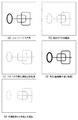
図2(a)〜(d)は、2値画像からアウトラインベクトルを抽出し、抽出したアウトラインベクトル表現を滑らかに関数近似したアウトラインベクトルを用いて所望の倍率で変倍された高画質のデジタル2値画像を得る一連の流れでの各段階でのデータの様子を示す図である。図2(a)は、入力されるラインアート画像の一例を示している。図2(b)は、図2(a)の2値画像から、特許文献1または特許文献2による手法で抽出される輪郭ベクトルデータを輪郭画像として描画して可視化したものである。図2(c)は、同抽出された輪郭ベクトルデータを特許文献3による手法で滑らかに関数近似して得られるアウトラインベクトルを描画して可視化したものである。図2(d)は、同平滑化(関数近似)されたベクトルに囲まれた領域を中塗りして得られる所望の倍率で変倍された高画質のデジタル2値画像の例である。
2 (a) to 2 (d) show high-quality
先述のように、ペーパーレス化への要求が高まりのもと、ビジネス文書においても、既存の画像データを電子化して再利用することが望まれている。原図のもつ各部分の部分的な太さの差や面積等をも、所望とされる変倍率を反映した形で(即ち、原図中での太い部分は変倍後の図中でも相対的に太く、原画中での細い部分では変倍後の図中でも相対的に細く)変倍するような再利用の形態に対しては、上述の特許文献1または特許文献2と特許文献3、若しくは、特許文献1または特許文献2と特許文献4により、オリジナル文書中の2値図形の輪郭(アウトライン)ベクトルを抽出して、2次元形状を任意の拡大縮小率で変倍することで、その実現が可能である。
As described above, with increasing demand for paperless printing, it is desired to digitize and reuse existing image data in business documents. Differences in thickness and area of each part of the original drawing also reflect the desired scaling factor (ie, the thick part in the original drawing is relatively thicker in the figure after scaling). The above-mentioned
しかしながら、例えば、ビジネス文書で既存の画像データを再利用する場合や、CAD/CAMシステム等で再利用する場合などに、図形を構成する1本の線を外部輪郭線と内部輪郭線との2本の輪郭線で表したデータよりも、ある図形を構成する1本の線を、線幅情報(線の太さや、線の面積に関する情報)を持たない単なる1本の線(直線、開曲線、閉曲線など)として扱いたい場合がある。 However, for example, when reusing existing image data in a business document or when reusing it in a CAD / CAM system or the like, one line constituting a figure is divided into two of an outer contour line and an inner contour line. A single line (straight line, open curve) that does not have line width information (information about the thickness of the line or the area of the line), rather than the data represented by the outline of the book. , Closed curve, etc.).
また、もともと太さを意識せずに、細線のみで描かれている線画の再利用の要望も強い。このような細線を再利用する場合、部分的な曲率や長さ等を変更したり、線の集まりの中から一部の線のみを削除したり、別な線を付与したり等の編集操作を行ってから利用することが多い。
上記の特許文献1や特許文献2による方法では、ラスタ走査順に記憶された2値画像から画像中の全ての輪郭線を抽出できる。しかしながら、太さを意識せずに、細線のみで描かれている線画や、ある図形を構成する線を、それぞれ、各線の端点や交点間をつなぐ独立した線や閉曲線の集まりとして抽出することができなかった。一方、上述した従来技術を用いて得られる図2(c)のようなアウトラインベクトルは、図形の線を外側の輪郭線と内側の輪郭線とで表現している。このようなアウトラインベクトルから、端点や交点をつなぐ線で構成される閉図形の集まりを抽出する場合、線図形から抽出される輪郭線のうち、外側輪郭線だけを用いると交点で線を分離することができず、1つの塊になってしまう。また一方、内側の輪郭線のみを用いると、図2(e)に示すように、部分図形間をつなぐ線分や閉図形をはみ出す線分のような部分に対応する輪郭ベクトルが欠落してしまう場合があり、不十分な処理となる。
In the methods according to
本発明は、上述の従来例の問題点に鑑みなされたものであり、細線化された2値画像を構成する線図形から輪郭情報を抽出し、抽出した輪郭情報に基づいて線図形を線芯化する画像処理技術を提供する。つまり、1本の線を、内側輪郭線と外側輪郭線の2本で表すのではなく、線の中心を通る1本の線で表すような画像処理技術を提供する。 The present invention has been made in view of the above-described problems of the conventional example, and extracts contour information from a line figure constituting a thinned binary image, and converts the line figure into a line core based on the extracted outline information. Image processing technology is provided. That is, an image processing technique is provided in which a single line is not represented by two lines of an inner contour line and an outer contour line but by a single line passing through the center of the line.
当該画像処理を行う際は、図形の端点や交点を検出し、それらの端点や交点に基づいて分離される線素あるいは閉曲線ごとに、線情報(ベクトルデータ)を生成する。 When performing the image processing, end points and intersections of the figure are detected, and line information (vector data) is generated for each line element or closed curve separated based on the end points or intersections.
更に、これらの画像処理を行う際、画像を走査する回数が少なく済むようにする。また、線素に分離した後、それぞれの線素に対してそのまま平滑化等の画像処理を行うと、線素の端点(つまり、図形の端点もしくは交点)の位置がずれてしまう場合があるので、ずれないようにする技術も提供する。 Furthermore, when performing these image processes, the number of times of scanning the image is reduced. In addition, if image processing such as smoothing is performed on each line element after separation into line elements, the position of the end points of the line elements (that is, the end points or intersections of the figures) may be shifted. Also provide technology to prevent misalignment.
上記課題を解決するために、本発明の画像処理装置は、
細線化された線図形の端点と交点とに基づいて、前記細線化された線図形の端点と端点の間、または端点と交点の間、または交点と交点の間をつなぐ線素または閉曲線ごとに前記細線化された線図形を分割し、当該分割された線素および閉曲線それぞれの輪郭情報を抽出する抽出手段と、
前記抽出手段で抽出された輪郭情報の位置を半画素単位に調整することにより、線芯化されたベクトルデータを生成する線芯化手段と、
を備えることを特徴とする。
In order to solve the above problems, an image processing apparatus according to the present invention provides:
Based on the endpoints and intersections of the thinned line figure, for each line element or closed curve that connects between the endpoints of the thinned line figure, or between the endpoints and the intersection, or between the intersections Extracting means for dividing the thin line figure and extracting contour information of each of the divided line elements and closed curves;
Adjusting the position of the contour information extracted by the extracting means in units of half pixels, thereby generating line-centered vector data;
It is characterized by providing.
本発明によれば、画像内の線を、中心を通る1本の線で表すことができる。 According to the present invention, a line in an image can be represented by a single line passing through the center.
また、ベクトルデータとして得られるので、再利用が容易になる。 Moreover, since it is obtained as vector data, reuse becomes easy.
さらに、線幅0の線として利用することが可能になる。 Further, it can be used as a line having a line width of zero.
(第1実施形態)
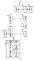
図1は本発明の実施形態に係る画像処理装置の機能ブロック図を示す図である。同図において、細線化済2値画像獲得部200は、2値画像入力部210で得た2値画像を、2値画像細線化部220で細線化する。2値画像入力部210は、スキャナ等の画像入力部211と、スキャン画像の2値化処理を行う2値化部212とで構成される。2値画像細線化部220では、縦横の4方向のいずれかで連結した連結画素(4−連結)に基づいて、2値画像の細線化処理を行うことによって、細線化された2値画像を出力する。即ち、スキャナ等の画像入力部211で光電走査により読み取られた画像データを公知の2値化部212で閾値処理により2値化する。そして、2値画像細線化部220では、例えば、公知の細線化手法であるHilditch法(酒井幸市著"デジタル画像処理の基礎と応用"第2版,ISBN4-7898-3707-6,CQ出版社,2004年2月1日発行,P.51-P.54,等)を用いて、当該得られた2値画像の細線化処理を行う。
(First embodiment)
FIG. 1 is a functional block diagram of an image processing apparatus according to an embodiment of the present invention. In the figure, the thinned binary
図3(a)は、2値画像細線化部220に入力される2値画像の一例を示す図である。図3(b)は、図3(a)を入力2値画像とした際の2値画像細線化部220から出力される細線化済画像を示す図である。 FIG. 3A is a diagram illustrating an example of a binary image input to the binary image thinning unit 220. FIG. 3B is a diagram showing a thinned image output from the binary image thinning unit 220 when FIG. 3A is used as an input binary image.
次に、細線化された2値画像を、端点間毎輪郭(周回)ベクトル抽出部300で処理する。1回のラスタ走査により、処理対象の細線化済2値画像中の線図形を、それらを構成している端点や交点間をつなぐ独立した線や閉曲線毎のそれぞれに対応したベクトル列の集まり(以降、「端点間毎線素粗輪郭ベクトル」と称する)として抽出し、処理結果を出力する。つまり、細線化された2値画像内に含まれる1画素幅の線図形を、図形の端点及び交点に基づいて、線素(直線あるいは開曲線)と閉曲線とに分割し、当該分割された線素または閉曲線ごとに、それらを囲む輪郭ベクトル列を抽出する処理が行われる。
Next, the thinned binary image is processed by the contour (circulation)
尚、出力される処理結果には、ベクトル列のそれぞれを構成する各ベクトルが、処理対象の線図形の端点(または交点)位置に対応する部分から抽出されたものか否か等を表す情報(以降、「付与情報」と称することがある)が含まれる。 The output processing result includes information indicating whether or not each vector constituting each vector string is extracted from a portion corresponding to the end point (or intersection) position of the line figure to be processed ( Hereinafter, it may be referred to as “grant information”).
端点や交点間をつなぐ線素や閉曲線毎に得られたベクトル列(端点間毎線素粗輪郭ベクトル)の集まり(輪郭情報)は、下記のような処理を行うことにより、図形を構成する線について、線幅情報を持たないベクトルデータ(もしくは線幅0のベクトルデータ)を生成する。このようにして生成された線幅情報の無いベクトルデータは、図形を構成する線を1本の線として再利用したい場合や、他のアプリケーションで線幅を変更したい場合などに適している。なお、以下では、付与情報と端点間毎線素粗輪郭ベクトルとを合わせて「端点間毎輪郭(周回)ベクトル」と称する。 A set of vector elements (line element rough contour vectors between end points) (contour information) obtained for each line element or closed curve that connects between end points and intersections is a line that forms the figure by performing the following processing. , Vector data having no line width information (or vector data having a line width of 0) is generated. The vector data without line width information generated in this way is suitable for the case where it is desired to reuse a line constituting a figure as a single line, or for the case where the line width is to be changed in another application. Hereinafter, the given information and the end-to-end-point line element rough contour vector are collectively referred to as “end-to-end-point contour (circulation) vector”.
端点間毎線芯(周回)ベクトル生成部310は、端点間毎輪郭(周回)ベクトル(端点間毎線素粗輪郭ベクトルと付与情報)が入力されると、付与情報を利用して各線素の端点位置を特定し、一画素幅(一画素単位)の線素を囲む輪郭(周回)ベクトルの各ベクトルの位置をそれぞれ半画素分ずつ予め定めた規則に基づいて決まる方向へ微調整することによって、幅0に線芯化された線素の周回ベクトルを表す端点間毎線芯(周回)化済ベクトルを生成する。
When each end-to-endpoint core (circumference)
図3(c)は、図3(b)を入力2値画像とした際の端点間毎輪郭(周回)ベクトル抽出部300から出力される端点間毎輪郭(周回)ベクトルを輪郭画像として描画して可視化した結果を示す図である。なお、図3(c)の上方に記載されている図は、端点間毎輪郭(周回)ベクトルを描画した図の一部を拡大した図であり、図形の交点部分では、交わっている線素の端点が重なっている。図3(d)は、端点間毎線芯(周回)ベクトル生成部310において端点間毎輪郭(周回)ベクトル(図3(c))が入力された場合に生成される端点間毎線芯(周回)化済ベクトルを、線画像として描画して可視化した結果を示す図である。
FIG. 3 (c) draws an end-to-end-point contour (circumference) vector output from the end-to-end-point contour (circumference)
端点間毎補助ベクトル入り(周回)ベクトル生成部320は、端点間毎線芯(周回)ベクトル生成部310から入力される端点間毎線芯(周回)化済ベクトルに対して、端点に相当する部分が端点として保存される(ベジェ曲線のアンカーポイントとなる)ようにするために、補助ベクトルを挿入付加して、端点間毎補助ベクトル入り(周回)ベクトルを生成する。これは、端点間毎補助ベクトル入り(周回)ベクトル平滑部330により平滑化処理(関数近似処理)される際に、端点部分に相当するベクトルが、他のベクトルと統合されて端点位置が不明にならないようにするための処理である。この処理の詳細は後述する。更に、補助ベクトルを挿入された各端点間毎補助ベクトル入り(周回)ベクトルのそれぞれに対し、どのベクトルが端点部にあたるかを明示する始端点・終端点情報を生成する。なお、端点のどちらが始点になるか終点になるかは、予め定めておいた規則に基づいて決定される。
The inter-endpoint auxiliary vector-containing (circumference)
図3(e)は、端点間毎補助ベクトル入り(周回)ベクトル生成部320で生成された端点間毎補助ベクトル入り(周回)ベクトルを線画像として描画して可視化した結果を示す図である。
FIG. 3 (e) is a diagram showing a result of drawing and visualizing an inter-endpoint auxiliary vector-containing (circumference) vector generated by the inter-endpoint auxiliary vector-containing (circumference)
端点間毎補助ベクトル入り(周回)ベクトル平滑部330は、端点間毎補助ベクトル入り(周回)ベクトル生成部320で生成された端点間毎補助ベクトル入り(周回)ベクトルに対して、各(周回)ベクトル毎に平滑化(関数近似)処理を行い、平滑化(関数近似)された平滑化(関数近似)済端点間毎補助ベクトル入り(周回)ベクトルを生成する。
The inter-endpoint auxiliary vector-containing (circumference)
端点間毎平滑化済ベクトル同定(非周回化)部340は、平滑化(関数近似)済端点間毎補助ベクトル入り(周回)ベクトルと、端点間毎補助ベクトル入り(周回)ベクトル生成部320より得られる始端点・終端点情報とが入力されると、各平滑化済の(周回)ベクトル毎にそれぞれ始端点と終端点となるベクトル部分を同定して、始端点と終端点の間を結ぶ非周回型のベクトル列(始端点から終端点へ向かう1方向のベクトル列)を生成する。そして、平滑化済ベクトル出力部350を介して、当該生成された端点間毎平滑化済非周回型ベクトルデータをファイル出力もしくは通信I/F等を介して外部装置に出力する。
The smoothed vector identification (non-circularization) unit 340 between the end points is obtained from the
図3(f)は、図3(e)の端点間毎補助ベクトル入り(周回)ベクトルに対して、平滑化と非周回化とを行うことにより生成される端点間毎平滑化済(非周回)ベクトルを線画像として描画して可視化した結果を示す図である。 FIG. 3 (f) shows a smoothed (non-rounded) interval between end points generated by performing smoothing and non-circularizing on the auxiliary vector (round) between end points in FIG. 3 (e). FIG. 4 is a diagram showing a result of rendering a vector as a line image and visualizing it.
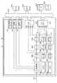
図4は、上述の機能ブロックによる処理を実現する画像処理装置の構成を例示する図である。同図において、518は、画像処理装置のバスを表している。1は図1の2値画像入力部210の画像入力部211を構成するスキャナである。2は画像メモリであり、3は画像入出力I/Oである。画像メモリ2は画像入出力I/O3を介して、スキャナ1で読み取られた2値化前の多値画像を保持したり、2値化された後の2値画像データを保持するものであり、ともに図1の220に示される2値画像細線化部を構成している。5は端点間毎輪郭(周回)ベクトル抽出部であり、図1の端点間毎輪郭(周回)ベクトル抽出部300を構成している。50は入力画像ラスタ走査部であり、画像入出力I/O3を介して信号線500より細線化済2値画像データを順次入力する。513と514は3×3の9画素で構成される走査窓の各画素の状態を入力する入力ポートである。4は、ネットワーク等を経由して、システムの外部と通信する通信I/Fである。519はCPUである。520はRAMで、ワーキングメモリである。6はROMで、後に説明する手順に沿ってCPU519で実行されるプログラムや予め定められるパラメータやデータ等を格納している。これらのCPU519やメモリ520、ROM6により、図1の端点間毎線芯(周回)ベクトル生成部310、端点間毎補助ベクトル入り(周回)ベクトル生成部320、端点間毎補助ベクトル入り(周回)ベクトル平滑部330、端点間毎平滑化済ベクトル同定(非周回化)部340が実現される。521はハードディスク522とのI/O(入出力回路)である。
FIG. 4 is a diagram exemplifying a configuration of an image processing apparatus that realizes the processing based on the above-described functional blocks. In the figure,
以下の説明では、主として、図5、図6、図10〜図25等を用いて端点間毎輪郭(周回)ベクトル抽出部300での処理内容を説明する。
In the following description, processing contents in the contour (circumference)
本実施形態では、図6に示すように、2値画像における注目画素(101)と、その近傍の8個の画素の状態を見て処理を進めるもので、注目画素をラスタ走査し、1画素毎にずらしながら画像全体の処理を逐次実行する。つまり、3x3の画素マトリクス単位で画像をラスタスキャンしながら検査していく。つまり、注目画素の画素値と周囲の画素の画素値とに基づいて検査していくことになる。 In the present embodiment, as shown in FIG. 6, the process proceeds by looking at the state of the target pixel (101) in the binary image and the eight neighboring pixels. The entire image is sequentially processed while shifting each time. That is, the image is inspected while performing raster scanning on a 3 × 3 pixel matrix basis. That is, the inspection is performed based on the pixel value of the target pixel and the pixel values of surrounding pixels.
図6において、×は注目画素101を表しており、「0」及び「2」で示された位置は、主走査方向に対し注目画素101と同じ位置にあり、且つ副走査方向にそれぞれ1ラスタ前の画素(0)及び1ラスタ先の画素(2)を示す。「1」及び「3」で示された位置は、注目画素101から主走査方向にそれぞれ1画素前の画素(3)及び1画素先の画素(1)を示している。更に、「A」及び「B」は、主走査方向に1画素先の位置で且つそれぞれ副走査方向に1ラスタ前及び1ラスタ先の位置にある画素を示す。また、「C」及び「D」は注目画素101から主走査方向に1画素前の位置で且つそれぞれ副走査方向に1ラスタ先及び1ラスタ前の位置にある画素を示す。
図5は、図4における端点間毎輪郭(周回)ベクトル抽出部5の構成例をより詳細に示す図である。同図において、図4と同様に50は入力画像ラスタ走査部であり、画像入出力I/O(3)を介して信号線500より細線化済2値画像データを順次入力する。
In FIG. 6, “x” represents the
FIG. 5 is a diagram showing in more detail an example of the configuration of the end-to-endpoint contour (circulation)
501は信号線500をより入力される画像データをやりとりするための入力制御(インターフエース)回路である。この信号線500よりラスタ走査形式で順次2値画像データが入力されてくる。502はラッチで、501より入力された画像データを、図示しない画素同期クロツクに同期して1画素づつ順次更新しながら保持する。次の画素同期クロツクにて、ラッチ502は次の画素データを入力制御回路501より入力する。この時、既に保持していた画素データは、その画素クロツクに同期してラッチ503にラッチされて、保持される。同様にラッチ503に保持されていた画素データは、次の画素同期クロツクにて、ラッチ504に保持される。
505及び506はそれぞれ1ラスタ分の画素データを保持するFIFO(ファーストイン・ファーストアウト・メモリ)である。FIFO505は、ラッチ504の出力を順次、画素同期クロツクに同期して取り込み、1ラスタ前のデータをラッチ507へ出力する。同様に、FIFO506も、ラッチ509の出力を取り込み、ラッチ510に1ラスタ前の画素データを出力する。ラッチ507、508、509及びラッチ510、511、512は共にラッチ502、503、504と全く同様に動作する。
このようにして、ラッチ502、503、504、507、508、509、510、511及び512に記憶された9個の画素は、図6に示した9(3×3)画素よりなる領域の画素データを記憶していることになる。即ち、これらラッチのデータは、それぞれ図6の"B","2","C","1","×","3","A","0","D"に対応している。
In this manner, the nine pixels stored in the
513と514は3×3の9画素で構成される走査窓の各画素の状態を入力する入力ポートである。513、514は共にCPU519の入力ポートで、入力ポート513は、ラッチ510、502、504、512のデータを、即ち、それぞれ図6における"A"、"B"、"C"、"D"の位置のデータをCPU519に入力する。同様に、入力ポート514はラッチ511、507、503、509、508のデータ、即ち、"0"、"1"、"2"、"3"、"×"の位置のデータとして入力する。
515は主走査方向の画素位置を示す主走査カウンタであり、図示しない副走査同期信号によりリセットされ、画素同期信号によりカウントアツプする。516は副走査方向の画素位置を示す副走査カウンタで、図示しないページ同期信号によりリセットされ、副走査同期信号によりカウントアツプされる。517は入出力制御用の入出力ポートであり、入力制御回路501に対し画素データ入力の実行及び保留を指示する信号、及び入力制御回路501よりCPU519への画素データ更新を知らせる信号等を保持する。521はハードディスク522の入出力制御装置である。入出力制御ポート517、主走査カウンタ515、副走査カウンタ516、入力ポート513、514、メモリ520、ディスクI/O521はバス518を介してCPU519に接続されている。
こうして、CPU519は入出力制御ポート517を介して、画素データの更新を行い、主走査カウンタ515及び副走査カウンタ516を介して、注目画素の画素位置(i,j)を知ることができる。また、入力ポート513及び514を介して、注目画素及びその近傍の8方向の画素の状態を知ることができる。
In this manner, the
注目画素の処理が終了すると、CPU519は入出力制御ポート517を介して9個のラッチに記憶される画素データの更新を指示し、同時に画素データの更新完了の信号をリセットする。入力制御回路501は、この更新の指示を受けると、画素データの更新指示の信号をクリアするとともに、後段のラッチにラッチされる画素データを更新し、この更新が終了すると入出力制御ポート517に、更新完了の信号を出力する。
When the processing of the pixel of interest is completed, the
CPU519は、更新指示の出力後、入出力制御ポート517より更新完了の信号が入力されるのを監視している。この更新完了の信号が入力されると、新たに9個のラッチに記憶された画素データに関する処理を実行し、以下同様の処理を繰り返す。また、入力制御回路501は、画像領域の最終画素を注目画素として処理し終えた際に、入出力制御ポート517に終了信号を出力する。
The
次に注目画素及びその近傍の8画素の状態に応じた、それぞれの場合の処理を説明する。注目画素が白画素である場合は、その処理を終了してラスタ走査を1画素分進め、注目画素位置を更新する。注目画素が黒画素の場合は、近傍の画素の状態によって以下の処理を行なう。 Next, processing in each case according to the state of the target pixel and the eight pixels in the vicinity thereof will be described. If the target pixel is a white pixel, the process is terminated, raster scanning is advanced by one pixel, and the target pixel position is updated. When the target pixel is a black pixel, the following processing is performed depending on the state of the neighboring pixels.
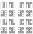
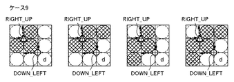
図10〜図25は、近傍画素の状態に応じて抽出される輪郭ベクトルを示す図である。図10〜図25において、内部が斜めのチェッカーパターンで埋められた大き目の○印は黒画素を示し、白画素は大き目の点線の○印で表記してある。「d」は"do no care"、即ち、「d」の表示のある位置の画素は白画素でも黒画素でも構わないことを示している。 10 to 25 are diagrams showing contour vectors extracted according to the state of neighboring pixels. 10 to 25, a large circle with an interior filled with an oblique checker pattern indicates a black pixel, and a white pixel is represented with a large dotted line. “D” indicates “do no care”, that is, a pixel at a position where “d” is displayed may be a white pixel or a black pixel.
また、図10〜図25の各画素マトリクスにおいて、黒丸「●」印、白丸「○」印は、横方向ベクトルの始点、縦方向ベクトルの終点を示している。また、黒三角「▲」印、白三角「△」印は縦方向ベクトルの始点、横方向ベクトルの終点を示している。これらのベクトルの始点・終点間の実線矢印は、始点及び終点共に定まった矢印の向く方向の輪郭ベクトルを表している。一方、点線矢印は、始点もしくは終点のいずれか一方のみが定まった、矢印の向く方向の輪郭ベクトルを表している。これら輪郭ベクトルの始点及び終点を総称して、以降、「輪郭点」と呼ぶことにする。 In each pixel matrix of FIGS. 10 to 25, the black circle “●” mark and the white circle “◯” mark indicate the start point of the horizontal vector and the end point of the vertical vector. The black triangle “▲” mark and the white triangle “Δ” mark indicate the start point of the vertical vector and the end point of the horizontal vector. A solid line arrow between the start point and the end point of these vectors represents a contour vector in the direction of the arrow determined for both the start point and the end point. On the other hand, the dotted arrow represents a contour vector in the direction of the arrow in which only one of the start point and the end point is determined. Hereinafter, the start point and the end point of these contour vectors are collectively referred to as “contour points”.
また、黒丸「●」印と黒三角「▲」印は端点部から抽出されるベクトルの始点・終点で、それぞれ端点部から抽出される横方向ベクトルの始点及び縦方向ベクトルの終点、端点部から抽出される縦方向ベクトルの始点及び横方向ベクトルの終点であることを示している。 Also, the black circle “●” and black triangle “▲” marks are the start and end points of the vector extracted from the end points, respectively, from the start point of the horizontal vector and the end and end points of the vertical vector extracted from the end points, respectively. It shows that it is the start point of the extracted vertical vector and the end point of the horizontal vector.
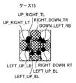
図10〜図25のそれぞれの輪郭点には、対応付けられる付与情報として、図9の一覧表に示した輪郭点情報の何れかが付記されているものとする。この輪郭点情報が、各輪郭点情報に付記されて抽出される付与情報となる。 Each of the contour points in FIGS. 10 to 25 is assumed to be appended with any of the contour point information shown in the list of FIG. 9 as associated information. This contour point information is added information that is appended to each contour point information and extracted.
図9のNo.01〜16に示される16種の輪郭点情報は、「xxx_yyy_zzz」または「xxx_yyy」なる形で表記されており、いずれも、"xxx"の部分は、対象の輪郭点が終点となるベクトルの向きを表し、"yyy"の部分は、同輪郭点が始点となるベクトルの向きを表している。上向きを UP 、下向きを DOWN 、右向きを RIGHT 、左向きを LEFT と表現する。例えば、No.01〜03はいずれも、上向きベクトルの終点かつ右向きベクトルの始点になっている輪郭点であることを意味している。 The 16 types of contour point information shown in No. 01 to No. 16 in FIG. 9 are expressed in the form of “xxx_yyy_zzz” or “xxx_yyy”. The direction of “yyy” represents the direction of the vector starting from the contour point. The upward direction is expressed as UP, the downward direction as DOWN, the right direction as RIGHT, and the left direction as LEFT. For example, Nos. 01 to 03 all mean contour points that are the end point of the upward vector and the start point of the right vector.
尚、「_zzz」の部分は、この付与情報をもつ輪郭点が、端点部から抽出されたものであることを意味していて、図9の端点情報の欄に記載してある。ここで、「_TL」は、線素の上端部の左側(Top Left)から抽出された端点であることを示し(図7(a)参照)、「_LT」は、線素の左端部の上側(Left Top)から抽出された端点であることを示している(図7(b)参照)。「_BR」は、線素の下端部の右側(Bottom Right)から抽出された端点であることを示し(図7(d)参照)、「_RB」は、線素の右端部の下側(Right Bottom)から抽出された端点であることを示している(図7(c)参照)。また、「_LB」は、線素の左端部の下側(Left Bottom)から抽出された端点であることを示し(図7(b)参照)、「_BL」は、線素の下端部の左側(Bottom Left)から抽出された端点であることを示している(図7(d)参照)。「_RT」は、線素の右端部の上側(Right Top)から抽出された端点であることを示し(図7(c)参照)、「_TR」は、線素の上端部の右側(Top Right)から抽出された端点であることを示している(図7(a)参照)。線素の端点ではない部分(以降、「非端点部」と称する)から抽出される輪郭点には、この「_zzz」部のない輪郭点情報が付与され、これらの例を図8(a)〜(d)に示す。但し、注目画素が黒画素の場合で、近傍の画素の状態によって、図10〜図25に各状態における輪郭点とその付与情報を抽出する際の実際の処理においては、上述の図9の輪郭点情報は図9の「値」の欄に対応する値をもって、抽出されるように構成するものとする。 The “_zzzz” portion means that the contour point having the given information is extracted from the end point portion, and is described in the end point information column of FIG. Here, “_TL” indicates an end point extracted from the left side (Top Left) of the upper end portion of the line element (see FIG. 7A), and “_LT” is an upper side of the left end portion of the line element. This indicates that the end point is extracted from (Left Top) (see FIG. 7B). “_BR” indicates an end point extracted from the bottom right side (Bottom Right) of the line element (see FIG. 7 (d)), and “_RB” indicates the lower side of the right end of the line element (Right It is shown that it is the end point extracted from (Bottom) (refer FIG.7 (c)). In addition, “_LB” indicates an end point extracted from the left bottom of the line element (Left Bottom) (see FIG. 7B), and “_BL” indicates the left side of the lower end of the line element. This indicates that the end point is extracted from (Bottom Left) (see FIG. 7D). “_RT” indicates an end point extracted from the upper right side (Right Top) of the line element (see FIG. 7C), and “_TR” indicates the right side (Top Right) of the upper end part of the line element. ) Is the end point extracted from (see FIG. 7A). Contour point information without this “_zzzz” portion is given to contour points extracted from portions that are not end points of line elements (hereinafter referred to as “non-endpoint portions”), and examples of these are shown in FIG. Shown in (d). However, in the case where the pixel of interest is a black pixel, the contour shown in FIG. It is assumed that the point information is extracted with a value corresponding to the “value” field in FIG.
図8において、黒画素は内部が斜めのチェッカーパターンの丸印で示され、白画素は点線の白丸印で表記されている。これら輪郭ベクトルの始点・終点位置は、主走査方向及び副走査方向共に、画素と画素の中間の位置にあるものとする。また、主走査方向及び副走査方向共に、画素のある位置は正整数で示され、画素位置を2次元の座標で表現する。但し、ここでは小数の表現を避けるために便宜上、以降の画素位置を偶数のみで表現することにし、始点、終点の位置を奇数の整数で表現することにする。 In FIG. 8, black pixels are indicated by a checker pattern circle with an interior, and white pixels are indicated by a dotted white circle. The start point and end point position of these contour vectors are assumed to be in the middle position between pixels in both the main scanning direction and the sub-scanning direction. Also, in both the main scanning direction and the sub-scanning direction, a certain pixel position is indicated by a positive integer, and the pixel position is expressed by two-dimensional coordinates. However, here, for the sake of convenience, in order to avoid the representation of decimal numbers, the subsequent pixel positions are represented by even numbers, and the positions of the start point and end point are represented by odd integers.
即ち、主走査方向m画素x副走査方向n画素の画像は、2mx2nの正の偶数(整数)の座標表現で表すものとする。このように、主走査方向をx座標、副走査方向をy座標とした2次元座標であらわすとき、これ以降2値画像は、それぞれがm画素よりなるnラスタで構成されるmxn画素(m、nは正の整数)でなるものとし、第j番目のラスタにおける第i番目の画素位置を(2i,2j)(i,jは正の整数で、i≦m,j≦n)で表現するものとする。また、主走査方向(x座標)は左から右に向かう方向が正の方向であり、副走査方向(y座標)は上から下に向かう向きが正の方向とする。 That is, an image of m pixels in the main scanning direction × n pixels in the sub-scanning direction is represented by 2mx2n positive even (integer) coordinate expression. As described above, when the two-dimensional coordinates are expressed with the x-coordinate in the main scanning direction and the y-coordinate in the sub-scanning direction, the binary image is thereafter expressed in mxn pixels (m, n is a positive integer), and the i-th pixel position in the j-th raster is represented by (2i, 2j) (i, j is a positive integer, i ≦ m, j ≦ n). Shall. The main scanning direction (x coordinate) is a positive direction from left to right, and the sub-scanning direction (y coordinate) is a positive direction from top to bottom.
以下、端点間毎輪郭(周回)ベクトル抽出部300の一連の動作を図26〜図28のフローチャートに従って説明する。
Hereinafter, a series of operations of the contour (circumference)
本実施形態の処理は、4方向の連結画素に基づいて細線化された2値画像において、端点と交点を検出しつつ、端点や交点をつなぐ互いに独立した線素や閉曲線の集まりとして、それぞれの線成分に対応する独立したベクトル群を抽出し、加えて、各輪郭点に輪郭点情報をも付与して抽出できる。したがって、その機能は特許文献1と大きく異なる。
In the binary image thinned based on connected pixels in four directions, the processing according to the present embodiment is performed by detecting the end points and the intersection points, and as a collection of mutually independent line elements and closed curves connecting the end points and the intersection points. Independent vector groups corresponding to line components can be extracted, and in addition, contour point information can be added to each contour point and extracted. Therefore, its function is significantly different from that of
また、図10〜図25に示したように使用する画素マトリクス(3画素×3画素)の画素パターン群も特許文献1と異なる。しかしながら、3画素×3画素の9画素で構成される走査窓を用いて、画像をラスタ走査し、逐次3画素×3画素の画素パターンとして注目画素とその近傍の8画素の状態を判断しながら、輪郭点を抽出していく点で、各3画素×3画素の画素パターンに応じた輪郭点と輪郭点情報の抽出する処理以外の処理は、基本的には特許文献1の開示する抽出動作と同様に構成することができる。
Further, the pixel pattern group of the pixel matrix (3 pixels × 3 pixels) used as shown in FIGS. However, the image is raster-scanned using a scanning window composed of 9 pixels of 3 pixels × 3 pixels, and the state of the pixel of interest and its neighboring 8 pixels are sequentially determined as a pixel pattern of 3 pixels × 3 pixels. In terms of extracting contour points, processes other than the process of extracting contour points and contour point information corresponding to each pixel pattern of 3 pixels × 3 pixels are basically the extraction operation disclosed in
図26は、本実施形態の画像処理装置のCPU519による輪郭抽出処理の全体の流れを示すフローチヤートである。まずステップS1において、2値画像データからベクトル列を各輪郭点に関する輪郭点情報とともに抽出する。そして、各ベクトルの始点の座標及びこのベクトルに流入してくる(このベクトルの始点の座標が終点となっている)ベクトル、流出してゆく(このベクトルの終点の座標が始点となっている)ベクトルを出力する。
FIG. 26 is a flowchart showing the overall flow of contour extraction processing by the
ステップS2において、流入及び流出ベクトルより、図29に示すような画像中の総輪郭線数(線素の総数)、輪郭線毎の輪郭点の総点数、輪郭線中の各点のx座標、y座標と各点の輪郭点情報の組み合わせを記憶したテーブルを作成する。 In step S2, from the inflow and outflow vectors, the total number of contour lines (total number of line elements) in the image as shown in FIG. 29, the total number of contour points for each contour line, the x coordinate of each point in the contour line, A table storing a combination of y coordinates and contour point information of each point is created.
次に、ステップS3に進み、ディスクI/O521を介して、このテーブル情報ファイル形式でハードディスク522に記憶して、一連の動作を終了する。
In step S3, the table information file format is stored in the
図27は図26のステップS1のベクトル列抽出処理を示すフローチヤートである。まずステップS11において、入力ポート514のビツト4(注目画素"X")を見ることにより、注目画素が白画素か黒画素かを判定する。白画素の場合はステップS13へ進み、黒画素の場合はステップS12へ進む。ステップS12では、注目画素の周囲8画素の状態を見て、その状態に応じた適当な処理ルーチンをコールし、輪郭ベクトルを抽出する。
FIG. 27 is a flowchart showing the vector string extraction process in step S1 of FIG. First, in step S11, it is determined whether the target pixel is a white pixel or a black pixel by looking at bit 4 (target pixel “X”) of the
ステップS13では、前述の如く入出力制御ポート517を介して画素位置の更新を指示する。そして、入出力制御ポート517より更新完了の信号を入力するとステップS14に進み、入出力制御ポート517を介して、最終画素の処理が終了したか否かを判断する。終了していなければステップS11へ戻り、次の注目画素も同様に処理を行う。一方、ステップS14で終了していると判断すれば、元のルーチンにリターンする。
In step S13, the pixel position is instructed to be updated via the input /
図28は図27のステップS12に示された周囲画素の状態により実行される処理を示すフローチヤートである。 FIG. 28 is a flowchart showing the processing executed according to the state of surrounding pixels shown in step S12 of FIG.
ステップS21において、CPU519のレジスタを「0」にクリアする。次に、ステップS22に進み、図6の「0」で示された位置の画素の状態(以下、「f(0)」で表現する)が黒画素(以降、「1」で表す)であれば、ステップS23へ進み、白画素(以降、「0」で表す)であればステップS24へ進む。
In step S21, the register of the
ステップS23ではレジスタの内容に1を加える。 In step S23, 1 is added to the contents of the register.
次に、ステップS24に進み、図6の「1」の位置の画素の状態が黒画素であれば(f(1)=1)、ステップS25へ進み、レジスタの内容に2を加える。f(1)=0であればステップS26に進み、同様に図6の「2」の位置の画素が黒画素かどうかを判断する。f(2)=1(黒画素であれば)であればステップS27へ進み、レジスタの内容に4を加える。
次にステップS28に進み、図6の「3」の位置の画素に注目し、f(3)=1ならステップS29へ進み、レジスタの内容に8を加えるが、そうでなければステップS30へ進む。ステップS30では、レジスタの保持する値の処理番号のルーチンをコールする。
Next, the process proceeds to step S24, and if the state of the pixel at the position “1” in FIG. 6 is a black pixel (f (1) = 1), the process proceeds to step S25, and 2 is added to the contents of the register. If f (1) = 0, the process proceeds to step S26, and similarly, it is determined whether or not the pixel at the position “2” in FIG. 6 is a black pixel. If f (2) = 1 (if it is a black pixel), the process proceeds to step S27, and 4 is added to the contents of the register.
Next, the process proceeds to step S28, paying attention to the pixel at the position “3” in FIG. 6. If f (3) = 1, the process proceeds to step S29, and 8 is added to the contents of the register. . In step S30, the routine of the process number of the value held in the register is called.
これにより、レジスタの内容は、図6に示した「0」、「1」、「2」、「3」の画素位置の各画素の状態に応じて、0〜15の値を取り得る。これらは、その値に応じてそれぞれ、図10の(ケース(case)0)、図11の(ケース1)、図12(ケース2)、図13(ケース3)、図14(ケース4)、図15(ケース5)、図16(ケース6)、図17(ケース7)、図18(ケース8)、図19(ケース9)、図20(ケース10)、図21(ケース11)、図22(ケース12)、図23(ケース13)、図24(ケース14)、図25(ケース15)に示されている。 Thereby, the contents of the register can take values of 0 to 15 depending on the state of each pixel at the pixel positions “0”, “1”, “2”, and “3” shown in FIG. These are (case 0), FIG. 11 (case 1), FIG. 12 (case 2), FIG. 13 (case 3), FIG. 14 (case 4), FIG. 15 (Case 5), FIG. 16 (Case 6), FIG. 17 (Case 7), FIG. 18 (Case 8), FIG. 19 (Case 9), FIG. 20 (Case 10), FIG. 22 (case 12), FIG. 23 (case 13), FIG. 24 (case 14), and FIG. 25 (case 15).
図28のステップS30において、図10〜図25に示される様に定義された輪郭点とその輪郭点情報とをそれぞれのケースに応じて抽出する。端点間毎輪郭(周回)ベクトル抽出部300は、1回のラスタ走査のみにより、4方向連結画素に基づいて細線化された2値画像(線図形)から、それらを構成している端点や交点間をつなぐ独立した線や閉曲線毎のそれぞれに対応したベクトル列の集まり(「端点間毎線素粗輪郭ベクトル」)と、その輪郭点情報とを抽出し、その処理結果を出力する。これらは、例えば、図29に示したような形式として出力される。同図における第一輪郭や第二輪郭、第a輪郭といったまとまりとして各線素から抽出されたベクトル列を表し、それらの輪郭点ごとに輪郭点情報が付与された形式となっている。
In step S30 of FIG. 28, the contour points defined as shown in FIGS. 10 to 25 and the contour point information are extracted according to each case. The edge-to-endpoint contour (circular)
図31に線図形の入力例と、これから抽出される端点間毎輪郭(周回)ベクトル、即ち、端点間毎線素粗輪郭ベクトル(細線化された線素を周回するベクトル列)と、輪郭点情報を示す。 FIG. 31 shows an input example of a line figure, a contour (circulation) vector between end points extracted from this, that is, a rough linear vector between end points (vector sequence that circulates a thin line element), and contour points Indicates information.
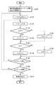
次に、図30に示すフローチャートにより、端点間毎線芯(周回)ベクトル生成部310の動作を説明する。ここでは、輪郭情報を半画素単位に調整して線芯化することになる。同図において、処理を開始すると、ステップS100において、端点間毎輪郭(周回)ベクトル抽出部300より得られた、端点間毎輪郭(周回)ベクトルを入力する。なお、端点間毎輪郭輪郭(周回)ベクトルは、線図形の端点(交点)位置に対応する部分から抽出されたものか否か等を表す情報(付与情報)と、端点や交点間をつなぐ線素(独立した線や閉曲線)毎のそれぞれに対応したベクトル列の集まり(端点間毎線素粗輪郭ベクトル)とで構成されている。
Next, the operation of the end-to-endpoint core line (circulation)
次に、ステップS110では、ステップS100で入力した図29に示したような形式の端点間毎輪郭(周回)ベクトルから、中に含まれる1つのベクトル列(図29の第k輪郭(1≦k≦a))を当面の処理対象としてステップS110が実行されるたびに順次昇順に定める。 Next, in step S110, one vector sequence (kth contour (1 ≦ k in FIG. 29) is included from the contours (circulation) vectors between the end points in the format shown in FIG. 29 inputted in step S100. .Ltoreq.a)) is determined as an ascending order every time step S110 is executed.
ステップS120では、S110で定めたベクトル列(総点数pとする)の中の1つのベクトルの輪郭点(第q点(1≦q≦p))を当面の処理対象としてステップS120が実行されるたびに順次昇順に定める。 In step S120, step S120 is executed with the contour point (qth point (1 ≦ q ≦ p)) of one vector in the vector sequence (the total number of points p) defined in S110 as the current processing target. Each time it is determined in ascending order.
ステップS130では、ステップS120で定めた輪郭点の輪郭点情報を参照して、この輪郭点を終点とするベクトルか、若しくは、この輪郭点を始点とするベクトルのいずれかが左向き(LEFT)か否かを判定し、左向きの場合は、ステップS140に進み、そうではない場合にはステップS150に進む。 In step S130, with reference to the contour point information of the contour point determined in step S120, whether the vector having this contour point as the end point or the vector having this contour point as the start point is leftward (LEFT). If it is leftward, the process proceeds to step S140. If not, the process proceeds to step S150.
ステップS140では輪郭点(座標値を(2i, 2j)とする)のy座標値を1減じて(副走査方向に半画素分原点側にずらして)、ステップS160に進む。 In step S140, the y coordinate value of the contour point (with coordinate values (2i, 2j)) is decremented by 1 (shifted to the origin side by half a pixel in the sub-scanning direction), and the process proceeds to step S160.
ステップS150では、輪郭点のy座標値を1増やして(副走査方向に半画素分原点とは反対側にずらして)、ステップS160に進む。 In step S150, the y coordinate value of the contour point is incremented by 1 (shifted to the opposite side from the origin by half a pixel in the sub-scanning direction), and the process proceeds to step S160.
ステップS160では、輪郭点の輪郭点情報を参照して、この輪郭点を終点とするベクトルか、もしくは、この輪郭点を始点とするベクトルのいずれかが上向きか否かを判定し、上向き(UP)の場合は、ステップS170に進み、そうではない場合にはステップS180に進む。 In step S160, referring to the contour point information of the contour point, it is determined whether either the vector having the contour point as the end point or the vector having the contour point as the starting point is upward, and the upward (UP ), The process proceeds to step S170; otherwise, the process proceeds to step S180.
ステップS170では輪郭点のx座標値を1増やして(主走査方向に半画素分原点とは反対側にずらして)、ステップS190に進む。 In step S170, the x-coordinate value of the contour point is increased by 1 (shifted to the opposite side from the origin by half a pixel in the main scanning direction), and the process proceeds to step S190.
ステップS180では、輪郭点のx座標値を1減じて(主走査方向に半画素分原点側にずらして)、ステップS190に進む。 In step S180, the x coordinate value of the contour point is decremented by 1 (shifted to the origin side by half a pixel in the main scanning direction), and the flow proceeds to step S190.
ステップS190では、ステップS110で定めたベクトル列内の全ての輪郭点の吟味が終わったか否かを判定し、そうであればステップS200へ進み、そうでなければ、同ベクトル列内の次の輪郭点にステップS130からステップS190までの処理を施すべくステップS120に戻る。 In step S190, it is determined whether or not all contour points in the vector sequence determined in step S110 have been examined. If so, the process proceeds to step S200. Otherwise, the next contour in the vector sequence is determined. The process returns to step S120 to perform the processing from step S130 to step S190 on the point.
ステップS200では、ステップS100で入力した端点間毎線素粗輪郭ベクトル中の全てのベクトル列の処理が終了したか否かを判定し、そうであればステップS210へ進み、そうでなければ、先のベクトル列に対してステップS120からステップS200までの処理を施すべくステップS110へ戻る。 In step S200, it is determined whether or not the processing of all vector sequences in the end-to-end line element rough contour vector input in step S100 has been completed. If so, the process proceeds to step S210. Return to step S110 to perform the processing from step S120 to step S200 on the vector sequence.
ステップS210では、ステップS100で入力した端点間毎線素粗輪郭ベクトルに対する処理結果を出力する。 In step S210, the processing result for the end-to-end line element rough contour vector input in step S100 is output.
尚、ステップS130やステップS160での判定は、先の図9における「値」欄の数値を輪郭点情報としているので、これらの数値を2進数で表現した際のLSBをbit0、MSBをbit7とすると、ステップ130ではbit2(図9では「右向(0)左向(1)」欄)を調べて、0なら右向き、1なら左向きと判定することができる。ステップ160ではbit3(図9では「上向(0)下向(1)」欄)を調べて、0なら上向き、1なら下向きと判定することができる。
端点間毎輪郭(周回)ベクトル抽出部300より得られた、端点間毎輪郭(周回)ベクトル(即ち、線図形の端点(交点)位置に対応する部分から抽出されたものか否か等を表す情報(付与情報)と、端点や交点間をつなぐ線素(独立した線や閉曲線)毎のそれぞれに対応したベクトル列の集まり(端点間毎線素粗輪郭ベクトル)とで構成される)を入力し、付与情報を利用して、一画素幅の幅を持った線素の輪郭(周回)ベクトルの各ベクトルの位置をそれぞれ半画素分ずつ相応する方向へ予め定める規則により微調整することによって、幅0に線芯化された端点間毎線芯(周回)化済ベクトルを生成する。なお、端点間毎線芯(周回)化済ベクトルもまた、例えば、図29に示したような形式として表現でき、本実施形態では、この形式で出力されるものとする。
In the determination in step S130 or step S160, the numerical value in the “value” column in FIG. 9 is used as the contour point information. Therefore, when these numerical values are expressed in binary numbers, the LSB is bit0 and the MSB is bit7. Then, in step 130, bit2 ("right (0) leftward (1)" column in FIG. 9) is examined, and if it is 0, it can be determined to be right, and if it is 1, it can be determined to be left. In step 160, bit 3 ("Upward (0) Downward (1)" field in FIG. 9) is examined, and it can be determined that 0 is upward and 1 is downward.
This represents the contour (circumference) vector between end points obtained by the contour (circumference)
図31に、端点間毎線素粗輪郭ベクトル(1画素幅の線素の周囲のベクトル列)と、輪郭点情報から幅0に線芯化された端点間毎線芯(周回)化済ベクトル(線素上に描かれたベクトル列)の例を示す。 FIG. 31 shows an end-to-end line element rough outline vector (a vector string around a line element having a width of 1 pixel) and an end-to-end-point line-to-end line core (around) vector that has been converted to a width of 0 from the outline point information. An example of (a vector sequence drawn on a line element) is shown.
次に、端点間毎補助ベクトル入り(周回)ベクトル生成部320の動作を説明する。端点間毎補助ベクトル入り(周回)ベクトル生成部320は、端点間毎補助ベクトル入り(周回)ベクトル平滑部330により平滑化(関数近似)処理される際に、端点部分に相当するベクトルが、他のベクトルと統合されて端点位置が不明にならぬように、端点部分に相当する部分が端点として保存される(ベジェ曲線のアンカーポイントとなる)ように補助ベクトルを挿入する。加えて、各平滑化済の(周回)ベクトル毎の始端点・終端点情報も生成する。この始端点・終端点情報は、次々工程である端点間毎平滑化済ベクトル同定(非周回化)部340において、平滑化(関数近似)済端点間毎補助ベクトル入り(周回)ベクトルから、各平滑化済の(周回)ベクトル毎にそれぞれの始端点と終端点となるベクトルを同定(判別)して、始端点と終端点の間の非周回型のベクトル列を生成するために用いられる。
Next, the operation of the inter-endpoint auxiliary vector-containing (circular)
本実施形態では、端点間毎補助ベクトル入り(周回)ベクトル平滑部330は、補助ベクトル入りのベクトルデータを平滑化するので、端点を保持した状態で、線芯化されたベクトルの平滑化を行うことができる。
In the present embodiment, the inter-endpoint auxiliary vector-containing (circular)
本実施形態に係る端点間毎補助ベクトル入り(周回)ベクトル平滑部330によれば、ベクトル平滑化(関数近似)の流れは、以下のとおりである。
According to the inter-endpoint auxiliary vector-containing (circular)
まず、粗輪郭データと称して、2値のラスタ画像のデータより抽出された、水平ベクトル、垂直ベクトルが交互に並ぶ構成となる輪郭データを入力とし、粗輪郭上の線分より接線線分を抽出する。 First, the outline data extracted from the binary raster image data and having the configuration in which the horizontal vector and the vertical vector are alternately arranged is input, and the tangent line segment is obtained from the line segment on the coarse outline. Extract.
抽出された接線線分よりアンカーポイントを抽出し、抽出されたアンカーポイント間の線分により構成されるグループを2次もしくは3次ベジェ曲線、及び直線をあてはめ、あるいは、ベジェ曲線近似を行い、3次もしくは2次のベジェ曲線により置き換えていく。 An anchor point is extracted from the extracted tangent line segment, and a group composed of the segment line between the extracted anchor points is applied to a quadratic or cubic Bezier curve and a straight line, or a Bezier curve approximation is performed. Replace with a second or second order Bezier curve.
ここで、アンカーポイントとして定めた点をもとに、アンカーポイント間にある輪郭点を1つのグループとして関数近似していく方法は、関数近似法としての基本的な手法である。また、アンカーポイントは、その間が、2次もしくは3次ベジェ曲線、及び直線のいずれに関数近似されたとしても、アンカーポイント自体の位置(座標値)は、変化しないという特徴をもつ。 Here, based on the points determined as anchor points, a method of function approximation of contour points between anchor points as one group is a basic method as a function approximation method. In addition, the anchor point has a feature that the position (coordinate value) of the anchor point itself does not change even if a function approximation is performed between the anchor point and a quadratic or cubic Bezier curve or a straight line.
本実施形態に係る端点間毎補助ベクトル入り(周回)ベクトル生成部320では、端点間毎線芯(周回)化済ベクトルの端点のそれぞれを、一方を始端点と他方を終端点とし、かつ、それらがともにアンカーポイントとなるように始端点と終端点間に補助ベクトル(補助輪郭点)を挿入していく処理をする。
In the inter-endpoint auxiliary vector-containing (circumference)
接線線分とするベクトルの抽出の条件としては、(1)注目するベクトルの前後のベクトルの向きが互いに逆向きであるもの、(2)抽出済みの主接線線分に隣接し、ベクトルの長さL1がL1≧θ1(パラメータ)を満たすもの、(3)ベクトルの長さL2がL2≧θ2(パラメータ)を満たすもの等が条件となる。ここで、条件に使用されるパラメータθ1〜θ2は、解像度に依存する一定値でもよく、また、アウトラインサイズ等のオブジェクトサイズにより、適応的に変更しても良い。 The conditions for extracting a vector as a tangent segment are as follows: (1) the vector direction before and after the vector of interest is opposite to each other; (2) the length of the vector adjacent to the extracted main tangent segment The length L1 satisfies L1 ≧ θ1 (parameter), (3) the vector length L2 satisfies L2 ≧ θ2 (parameter), and the like. Here, the parameters θ1 to θ2 used for the conditions may be fixed values depending on the resolution, or may be adaptively changed according to the object size such as the outline size.
アンカーポイントの抽出に関して、抽出された接線線分上に新たな点を抽出し、それをアンカーポイントとする。アンカーポイントは接線線分の端2つに対しそれぞれ抽出される。よって、一つの接線線分に対し2つのアンカーポイントが抽出されるが、2つのアンカーポイントが一致した場合には一つのアンカーポイントのみ抽出されることになる。2つのアンカーポイントが抽出される場合は、アンカーポイントに挟まれた部位は自動的にオブジェクト上の直線となる。接線線分上の一つの端点に対するアンカーポイント抽出方法としては、注目する接線線分であるベクトルに隣接するベクトルが接線線分であれば、この隣接する側の端点をアンカーポイントとすることができる。 Regarding the extraction of the anchor point, a new point is extracted on the extracted tangent line segment, and is used as the anchor point. Anchor points are extracted for each of the two ends of the tangent line segment. Therefore, two anchor points are extracted for one tangent line segment, but when the two anchor points match, only one anchor point is extracted. When two anchor points are extracted, the part sandwiched between the anchor points automatically becomes a straight line on the object. As an anchor point extraction method for one end point on a tangent line segment, if the vector adjacent to the vector that is the target tangent line segment is a tangent line segment, the end point on the adjacent side can be used as the anchor point. .
そこで、端点間毎補助ベクトル入り(周回)ベクトル生成部320は、点間毎線芯(周回)化済ベクトルの端点のそれぞれを、一方を始端点とし、他方を終端点とし、かつ、それらがともにアンカーポイントとなるように、補助点を挿入する。
Therefore, the inter-point-to-end auxiliary vector-added (circumference)
図32(a)を用いて、始端点としたい端点P0の直前に挿入する補助輪郭点P-1の挿入方法を説明する。補助輪郭点P-1を始点とする補助ベクトルV-1が、始端点としたい端点P0の直後の輪郭点P1を始点とするベクトルV1と逆向きになるように、補助輪郭点P-1を定める。このようにすれば、接線線分の抽出条件の(1)から、ベクトルV0が接線線分となる。 A method of inserting the auxiliary contour point P −1 to be inserted immediately before the end point P 0 desired to be the start end point will be described with reference to FIG. The auxiliary contour point P is such that the auxiliary vector V -1 starting from the auxiliary contour point P -1 is opposite to the vector V 1 starting from the contour point P 1 immediately after the end point P 0 desired to be the starting end point. Set -1 . In this way, the vector V 0 becomes the tangent line segment from the extraction condition (1) of the tangent line segment.
また、補助輪郭点P-1を始点とする補助ベクトルV-1が上述の接線線分の抽出条件の(3)を満たすように十分な長さを持つようにする。このようにすれば、補助ベクトルV-1もまた接線線分となる。補助ベクトルV-1とベクトルV0とが共に接線線分となることにより、上述のアンカーポイント抽出方法における「注目する接線線分であるベクトルに隣接するベクトルが接線線分であれば、この隣接する側の端点をアンカーポイントとする」という条件から、始端点としたい端点P0をアンカーポイントとすることができる。
次に、図32(b)を用いて、終端点としたい端点Pnの直後に挿入する補助輪郭点Pn+1の挿入方法を説明する。補助輪郭点Pn+1を終点とする補助ベクトルVnが、終端点としたい端点Pnの直前の輪郭点Pn-1を終点とするベクトルVn-2と逆向きになるように、補助輪郭点Pn+1を定める。このようにすれば、上述の抽出条件(1)から、ベクトルVn-1が接線線分となる。また、補助輪郭点Pn+1を終点とする補助ベクトルVnが上述の接線線分の抽出条件(3)を満たすように十分な長さを持つようにする。このようにすれば、補助ベクトルVnもまた接線線分となる。
Further, the auxiliary vector V −1 starting from the auxiliary contour point P −1 is made to have a sufficient length so as to satisfy the above extraction condition (3) of the tangent line segment. In this way, the auxiliary vector V −1 is also a tangent line segment. Since both the auxiliary vector V -1 and the vector V 0 are tangent segments, in the above-described anchor point extraction method, if the vector adjacent to the vector that is the tangent segment of interest is a tangent segment, From the condition that “the end point on the side to be used is an anchor point”, the end point P 0 desired to be the start end point can be set as the anchor point.
Next, a method of inserting the auxiliary contour point P n + 1 to be inserted immediately after the end point P n desired to be the end point will be described with reference to FIG. The auxiliary vector V n whose end point is the auxiliary contour point P n + 1 is opposite to the vector V n-2 whose end point is the contour point P n-1 immediately before the end point P n desired to be the end point. An auxiliary contour point P n + 1 is determined. In this way, the vector V n-1 becomes a tangent line segment from the above extraction condition (1). Further, the auxiliary vector V n having the auxiliary contour point P n + 1 as an end point has a sufficient length so as to satisfy the extraction condition (3) of the tangent line segment. In this way, the auxiliary vector V n is also a tangent line segment.
補助ベクトルVn-1とベクトルVnとが共に接線線分となることにより、上述のアンカーポイント抽出方法における「注目する接線線分であるベクトルに隣接するベクトルが接線線分であれば、この隣接する側の端点をアンカーポイントとする」という条件から、終端点としたい端点Pnをアンカーポイントとすることができる。 Since the auxiliary vector V n-1 and the vector V n are both tangent line segments, in the anchor point extraction method described above, if the vector adjacent to the vector that is the target tangent line segment is a tangent line segment, From the condition that “the end point on the adjacent side is an anchor point”, the end point P n desired to be the end point can be set as the anchor point.
このように、始端点と終端点がアンカーポイントになるように、それぞれ、始端点の直前への挿入点と、終端点の直後への挿入点を定めたのち、これらの挿入点が水平ベクトルと垂直ベクトルの連続で連結される。始端点から終端点までの本来の輪郭点列と、終端点の直後から始端点の直前までの挿入点を経て再び始端点につながる一連の輪郭点列を生成する。更に、この一連の輪郭点列の中で、どれが、始端点と終端点であるかを同定するための情報とを加えた始端点・終端点情報を生成する。本実施形態では、輪郭点列中の始端点の座標値と終端点の座標値そのものを改めて別途生成することで、始端点・終端点情報とする。 In this way, after defining the insertion point immediately before the start point and the insertion point immediately after the end point so that the start point and the end point become anchor points, respectively, these insertion points are defined as horizontal vectors. Concatenated with a series of vertical vectors. An original contour point sequence from the start point to the end point and a series of contour point sequences connected to the start point again through the insertion point immediately after the end point and immediately before the start point are generated. Furthermore, start point / end point information is generated by adding information for identifying which is the start point and the end point in the series of contour point sequences. In this embodiment, the coordinate values of the start point and the end point in the contour point sequence are generated separately to obtain the start point / end point information.
次に、図33に示すフローチャートにより、端点間毎補助ベクトル入り(周回)ベクトル生成部320の動作を説明する。
Next, the operation of the inter-endpoint auxiliary vector-containing (circular)
ステップS300において、端点間毎線芯(周回)ベクトル生成部310より得られた、幅0に線芯化された端点間毎線芯(周回)化済ベクトルを入力する。
In step S300, the inter-endpoint line-core (circumference) vector obtained by the inter-endpoint line-core (circumference)
次に、ステップS310では、ステップS300で入力した図29に示す形式の端点間毎線芯(周回)化済ベクトルから、その中に含まれる1つのベクトル列(図29の第k輪郭(1≦k≦a))を当面の処理対象とする。 Next, in step S310, one vector sequence (kth contour (1 ≦ 1 in FIG. 29) included in the inter-endpoint line-to-line (circumference) completed vector input in step S300 is used. Let k ≦ a)) be the current processing target.
次に、ステップS320では、S310で定めたベクトル列(総点数pとする)の中の1つのベクトルの輪郭点(第q点(1≦q≦p))を処理対象として定め、ステップS330で始端点か否か判断する。ステップS330で始端点が見つけられるまでの間、ステップS320が実行されるたびに第1点から第p点までを昇順に順次1点ずつ処理対象として定める。 Next, in step S320, the contour point (qth point (1 ≦ q ≦ p)) of one vector in the vector sequence (denoted by the total number p) determined in S310 is determined as a processing target, and in step S330. Judge whether it is the start point. Until the starting point is found in step S330, each time step S320 is executed, the first point to the pth point are sequentially set as processing targets one by one in ascending order.
次に、ステップS330では、ステップS320で定めた輪郭点の輪郭点情報を参照して、この輪郭点が始端点とすべきベクトルか否かを判定する。この輪郭点が始端点とすべきベクトルの場合は、ステップS360に進み、そうではない場合にはステップS340に進む。ここで、輪郭点が始端点とすべきベクトルか否かは、その輪郭点の輪郭点情報を参照して、先に説明した図9で表記しているところの「UP_RIGHT_LT(03H)」、「DOWN_LEFT_RB(0FH)」、「LEFT_UP_BL(17H)」、「RIGHT_DOWN_TR(1BH)」のいずれかであるか否かにより判定する。これらは、図9の「値」の数値の bit1 と bit0 が共に「1」であるか否かを調べることで実現することもできる。
Next, in step S330, with reference to the contour point information of the contour point determined in step S320, it is determined whether or not this contour point is a vector to be the starting point. If this contour point is a vector to be the starting end point, the process proceeds to step S360, and if not, the process proceeds to step S340. Here, whether or not the contour point is a vector to be set as the start point is referred to by referring to the contour point information of the contour point, “UP_RIGHT_LT (03H)”, “ Judgment is made based on whether it is one of “DOWN_LEFT_RB (0FH)”, “LEFT_UP_BL (17H)”, or “RIGHT_DOWN_TR (1BH)”. These can also be realized by checking whether or not both the
ステップS340では、ステップS310で入力した端点間毎線芯(周回)化済ベクトルの中に含まれる1つのベクトル列中の全てのベクトルの処理が終了したか否かを判定する。終了していなければ、該当するベクトル列中の次のベクトルに対してステップS330の判定を施すべくステップS320へ戻る。 In step S340, it is determined whether or not the processing of all the vectors in one vector sequence included in the inter-endpoint line-core (circulation) completed vector input in step S310 has been completed. If not completed, the process returns to step S320 to make the determination in step S330 for the next vector in the vector sequence.
一方、ステップS310で入力したベクトル列中に、始端点候補が存在しなかった場合は1ベクトル列の処理が終了したと判定して、ステップS350へ進む。 On the other hand, when the starting point candidate does not exist in the vector sequence input in step S310, it is determined that the processing of one vector sequence is completed, and the process proceeds to step S350.
ステップS350において、ベクトル列は端点のない閉ループである旨を示す閉ループマーカをベクトル列に対して付与した上で、それに加えて、ベクトル列中の一連の各ベクトルをそのまま出力する。 In step S350, a closed loop marker indicating that the vector sequence is a closed loop without end points is added to the vector sequence, and in addition, a series of vectors in the vector sequence are output as they are.
図37(a)は、ステップS350で出力するデータ形式を例示する図である。対象としたベクトル列を第s番目の輪郭とすると、そのベクトル列中にはv個のベクトルが含まれている。 FIG. 37A is a diagram illustrating a data format output in step S350. If the target vector sequence is the sth contour, v vectors are included in the vector sequence.
尚、閉ループマーカとして、端点座標としては本来ありえない(-1,-1)の座標値を2点分の始端点・終端点情報として付与する。 As a closed loop marker, a coordinate value of (-1, -1), which is not possible as an end point coordinate, is given as start / end point information for two points.
ステップS350の処理を終えると、ステップS420へ処理を進める。 When the process of step S350 is completed, the process proceeds to step S420.
一方、ステップS360において、輪郭点を始端点として登録し、かつ、その他の輪郭点とともに出力してステップS370へ処理を進める。 On the other hand, in step S360, the contour point is registered as a starting point, and is output together with other contour points, and the process proceeds to step S370.
ステップS370では、ステップS310で定めたベクトル列(総点数pとする)の中から、前記登録した始端点の次の輪郭点から順に、1つのベクトルの輪郭点(第q点(1≦q≦p))を入力する。そして、ステップS380で終端点が見つけられるまでの間、ステップS370で最初に定められた輪郭点以降の点から第p点に向けて昇順に順次1点ずつ当面の処理対象として定め、ステップS380に処理を進める。 In step S370, one vector contour point (q-th point (1 ≦ q ≦ 1) is sequentially selected from the vector sequence defined in step S310 (the total number of points is p) from the contour point next to the registered start point. p)). Then, until the end point is found in step S380, the points are determined as current processing objects one by one in ascending order from the point after the contour point first determined in step S370 toward the pth point, and in step S380. Proceed with the process.
次に、ステップS380では、先のステップS370で定めた輪郭点の輪郭点情報を参照して、この輪郭点が終端点とすべきベクトルか否かを判定する。この輪郭点が終端点とすべきベクトルの場合は、ステップS400に処理を進め、そうではない場合にはステップS390に処理を進める。 Next, in step S380, it is determined with reference to the contour point information of the contour point determined in the previous step S370 whether or not this contour point is a vector to be the end point. If this contour point is a vector to be the end point, the process proceeds to step S400, and if not, the process proceeds to step S390.
ここで、輪郭点が終端点とすべきベクトルか否かは、その輪郭点の輪郭点情報を参照して、先に説明した図9で表記している「UP_RIGHT_TL(01H)」、「DOWN_LEFT_BR(0DH)」、「LEFT_UP_LB(15H)」、「RIGHT_DOWN_RT(19H)」のいずれかであるか否かをもってその判定を行なう。これらは、図9の「値」の数値の bit1 と bit0 がそれぞれ 「0」 と 「1 」であるか否かを調べることで実現することもできる。
Here, whether or not the contour point is a vector to be the end point is referred to by referring to the contour point information of the contour point, “UP_RIGHT_TL (01H)” and “DOWN_LEFT_BR ( 0DH) ”,“ LEFT_UP_LB (15H) ”, and“ RIGHT_DOWN_RT (19H) ”. These can also be realized by checking whether
ステップS390では、当該処理対象の輪郭点を、始端点〜終端点間を構成するベクトルの1つとして出力してステップS370へ戻る。 In step S390, the contour point to be processed is output as one of vectors constituting the start point to the end point, and the process returns to step S370.
ステップS400では、当該処理対象の輪郭点を終端点として登録し、かつ、ステップS390で出力された輪郭点を始端点〜終端点間を構成するベクトルとして出力してステップS410へ進む。 In step S400, the contour point to be processed is registered as an end point, and the contour point output in step S390 is output as a vector constituting the start point to the end point, and the process proceeds to step S410.
ステップS410では、ベクトル列の始端点と終端点の両方が定まり、かつ、始端点〜終端点間の一連の各ベクトルも出力された状態となっており、ここでは、終端点〜始端点の間に挿入される一連の補助ベクトルを求める。ステップS410の内容は、図34に示すフローチャートと図35及び図36を用いて後に詳細に説明する。ステップS410の処理を終えるとステップS420へ処理を進める。 In step S410, both the starting point and the ending point of the vector sequence are determined, and a series of vectors between the starting point and the ending point are also output. Here, between the ending point and the starting point, Find a series of auxiliary vectors to be inserted into. The contents of step S410 will be described in detail later with reference to the flowchart shown in FIG. 34 and FIGS. 35 and 36. When the process of step S410 is completed, the process proceeds to step S420.
ステップS420では、ステップS300で入力した端点間毎線芯(周回)化済ベクトル中の全てのベクトル列の処理が終了したか否かを判定する。全てが終了していればステップS430へ進み、終了していなければ、次のベクトル列に対してステップS310からステップS410までの処理を施すべくステップS310へ戻る。 In step S420, it is determined whether or not the processing of all vector sequences in the inter-endpoint line-to-core (circumference) input vector input in step S300 has been completed. If all of them have been completed, the process proceeds to step S430. If not, the process returns to step S310 to perform the processing from step S310 to step S410 on the next vector sequence.
ステップS430では、ステップS300で入力した端点間毎線芯(周回)化済ベクトルに対する処理結果を出力する。 In step S430, the processing result for the end-to-endpoint core line (circulation) input vector input in step S300 is output.
図37(b)は、対象としたベクトル列に、始端点・終端点の両方が定まり、且つ、始端点〜終端点間の一連の各ベクトルと、終端点〜始端点の間に挿入される一連の補助ベクトルが求まった場合に出力されるベクトル列に対する出力例を示す図である。同図において、対象としたベクトル列は第u番目とし、そのベクトル列中には始端点と終端点自身も含めて始端点〜終端点間の一連の各ベクトルがt個含まれている。更に、終端点〜始端点の間に挿入される一連の補助ベクトルがr個含まれている。ここで、第1点は、始端点そのものであり、第t点は、終端点そのものとなっている。 In FIG. 37 (b), both the start point and the end point are determined in the target vector sequence, and a series of vectors between the start point and the end point are inserted between the end point and the start point. It is a figure which shows the example of an output with respect to the vector sequence output when a series of auxiliary | assistant vectors are calculated | required. In the same figure, the target vector sequence is the u-th, and the vector sequence includes t series of vectors between the start point and the end point including the start point and the end point itself. Furthermore, r auxiliary series inserted between the end point and the start point are included. Here, the first point is the start point itself, and the t-th point is the end point itself.
次に、図34に示すフローチャートにより、図33に示すフローチャートのステップS410の処理の内容を更に説明する。ここでは、ベクトル列の始端点と終端点の両方が定まり、かつ、始端点〜終端点間の一連の各ベクトルも出力された状態となっている。そして、終端点〜始端点の間に挿入される一連の補助ベクトルを求めるのが本フローチャートの処理内容である。本処理は、図33と同様に、端点間毎補助ベクトル入り(周回)ベクトル生成部320により実行される。
Next, the contents of the process in step S410 of the flowchart shown in FIG. 33 will be further described with reference to the flowchart shown in FIG. Here, both the starting point and the ending point of the vector sequence are determined, and a series of vectors between the starting point and the ending point are also output. The processing content of this flowchart is to obtain a series of auxiliary vectors inserted between the terminal point and the starting point. This process is executed by the
ステップS411では、先に図32(a)を用いて説明したように、始端点としたい端点P0の直前に挿入する補助輪郭点P-1の座標値を求める。即ち、補助輪郭点P-1を始点とする補助ベクトルV-1が、始端点としたい端点P0の直後の輪郭点P1を始点とするベクトルV1と逆向きになるように、かつ、補助輪郭点P-1を始点とする補助ベクトルV-1が上述の接線線分の抽出条件(3)を満たすように十分な長さ(例えば、10画素長以上)を持つように補助輪郭点P-1を定める。 In step S411, as described with reference to FIG. 32 (a) above, determine the coordinate values of the auxiliary contour point P -1 to be inserted just before the end point P 0 to be the starting point. That is, the auxiliary vector V −1 starting from the auxiliary contour point P −1 is opposite to the vector V 1 starting from the contour point P 1 immediately after the end point P 0 desired to be the starting end point, and Auxiliary contour points so that the auxiliary vector V -1 starting from the auxiliary contour point P -1 has a sufficient length (for example, 10 pixels or more) so as to satisfy the extraction condition (3) of the tangent line. Define P -1 .
次に、ステップS412において、先に図32(b)を用いて説明したように、終端点としたい端点Pnの直後に挿入する補助輪郭点Pn+1の座標値を求める。即ち、補助輪郭点Pn+1を終点とする補助ベクトルVnが、終端点としたい端点Pnの直前の輪郭点Pn-1を終点とするベクトルVn-2と逆向きになるように、かつ、補助輪郭点Pn+1を終点とする補助ベクトルVnが上述の接線線分の抽出条件(3)を満たすように十分な長さ(例えば、10画素長以上)を持つように補助輪郭点Pn+1を定める。 Next, in step S412, as described above with reference to FIG. 32 (b), the coordinate value of the auxiliary contour point P n + 1 to be inserted immediately after the end point P n desired to be the end point is obtained. That is, the auxiliary vector V n whose end point is the auxiliary contour point P n + 1 is opposite to the vector V n-2 whose end point is the contour point P n-1 immediately before the end point P n desired to be the end point. In addition, the auxiliary vector V n whose end point is the auxiliary contour point P n + 1 has a sufficient length (for example, a length of 10 pixels or more) so as to satisfy the extraction condition (3) of the tangent line. A supplemental contour point P n + 1 is determined.
ステップS413では、ステップS411で求めた始端点としたい端点P0の直前に挿入する補助輪郭点P-1を始点とする補助ベクトルV-1と、ステップS412で求めた終端点としたい端点Pnの直後に挿入する補助輪郭点Pn+1を終点とする補助ベクトルVnが、共に水平ベクトルとなっているか、あるいは、共に垂直ベクトルとなっているかを判定する。 In step S413, an auxiliary vector V −1 starting from the auxiliary contour point P −1 inserted immediately before the end point P 0 desired to be the start point obtained in step S411 and an end point P n desired to be the end point obtained in step S412 are obtained. It is determined whether the auxiliary vector V n having the auxiliary contour point P n + 1 inserted immediately after the end point is a horizontal vector or a vertical vector.
共に水平ベクトル、あるいは、共に垂直ベクトルの場合は、処理をステップS414に進める。一方、ステップS413の判定で、共に水平ベクトル、あるいは、共に垂直ベクトルでない場合は、処理をステップS416に進める。 If both are horizontal vectors or both are vertical vectors, the process advances to step S414. On the other hand, if it is determined in step S413 that both are not horizontal vectors or both are vertical vectors, the process proceeds to step S416.
V-1とVnが、共に水平ベクトルとなっているか、あるいは、共に垂直ベクトルとなっている場合の例を図35に示す。 FIG. 35 shows an example in which V −1 and V n are both horizontal vectors or both are vertical vectors.
ステップS414では終端点としたい端点Pnの次の次にあたる補助輪郭点Pn+2を、Pn+1からみてP-1から遠くなる方向に、上述の接線線分の抽出条件(3)を満たすように、Pn+2を終点とするベクトルVn+1が十分な長さ(例えば、10画素長以上)を持つように定める。 In step S414, the auxiliary contour point P n + 2 next to the end point P n to be set as the end point is extracted in the direction farther from P −1 as viewed from P n + 1 than the above tangent line segment extraction condition (3). The vector V n + 1 whose end point is P n + 2 is determined to have a sufficient length (for example, 10 pixels or more) so as to satisfy the above.
そして、ステップ415において、水平ベクトルと垂直ベクトルが交互につながるような形式で、Pn+2とP-1を連結する様に、終端点としたい端点Pnの3点後の補助輪郭点(この点は、始端点としたい端点P0の2点前の補助輪郭点でもある)である点Pn+3を定める。このようにして補助輪郭点Pn+1,Pn+2,Pn+3,P-1が定まる。そして、補助点挿入の一連のステップを終え、図33のフローチャートのS420にもどる。 Then, in step 415, auxiliary contour points (3 points after the end point P n desired to be the end point are connected so that P n + 2 and P −1 are connected in such a manner that the horizontal vector and the vertical vector are alternately connected. This point defines a point P n + 3 that is also an auxiliary contour point two points before the end point P 0 to be set as the start point. In this way, auxiliary contour points P n + 1 , P n + 2 , P n + 3 , P −1 are determined. Then, the series of steps for inserting auxiliary points is completed, and the process returns to S420 in the flowchart of FIG.
一方、ステップS416は、V-1とVnの、どちらか一方が水平ベクトルとなっていて、他方は垂直ベクトルとなっている場合の処理であり、この場合の例を図36に示す。 On the other hand, step S416 is processing when one of V -1 and V n is a horizontal vector and the other is a vertical vector. An example of this case is shown in FIG.
ステップS416では終端点としたい端点Pnの次の次にあたる補助輪郭点Pn+2を、Pn+1からみてP-1から遠くなる方向に、接線線分の抽出条件(3)を満たすように、Pn+2を終点とするベクトルVn+1が十分な長さ(例えば、10画素長以上)を持つように定める。 In step S416, the auxiliary contour point P n + 2 next to the end point P n to be set as the end point satisfies the extraction condition (3) of the tangent line segment in the direction far from P −1 when viewed from P n + 1. Thus, the vector V n + 1 whose end point is P n + 2 is determined to have a sufficient length (for example, a length of 10 pixels or more).
ステップS417では、点Pn+3を、Pn+2からみてP-1から遠くなる方向に、上述の接線線分の抽出条件(3)を満たすように、Pn+3を終点とするベクトルVn+2が十分な長さ(例えば、10画素長以上)を持つように定める。 In step S417, the point P n + 3, in a direction away from the P -1 Te P n + 2 viewed from so as to satisfy the extraction condition of the above tangential line (3), and ending the P n + 3 The vector V n + 2 is determined to have a sufficient length (for example, 10 pixels or more).
ステップ418では、水平ベクトルと垂直ベクトルが交互につながるような形式で、Pn+3とP-1を連結する様に、終端点としたい端点Pnの4点後の補助輪郭点(この点は始端点としたい端点P0の2点前の補助輪郭点でもある)である点Pn+4を定める。このようにして補助輪郭点Pn+1,Pn+2,Pn+3,Pn+4,P-1が定まる。そして、補助点挿入の一連のステップを終え、図33のフローチャートのS420にもどる。
In step 418,
端点間毎補助ベクトル入り(周回)ベクトル生成部320は、端点間毎線芯(周回)ベクトル生成部310より得られる上記の端点間毎線芯(周回)化済ベクトルを入力する。そして、次工程の処理をする端点間毎補助ベクトル入り(周回)ベクトル平滑部330により平滑化(関数近似)処理される際に、端点部分に相当するベクトルが、他のベクトルと統合されて端点位置が不明にならないように、端点部分に相当する部分が端点として保存される(ベジェ曲線のアンカーポイントとなる)ように補助ベクトルを挿入することにより、端点間毎補助ベクトル入り(周回)ベクトルを生成する。
The inter-endpoint auxiliary vector-added (circumference)
加えて、補助ベクトルが挿入された各端点間毎補助ベクトル入り(周回)ベクトルのそれぞれに対し、どのベクトルが端点部にあたるかを明示する始端点・終端点情報をも生成する。生成された処理結果は、例えば、図29に示したような形式の各輪郭データ部分のそれぞれを図37(a)や図37(b)の各ベクトル列データに置き換えた形として表現でき、本実施形態では、この形式で出力が可能である。 In addition, start point / end point information that clearly indicates which vector corresponds to the end point portion is generated for each of the end point-to-end auxiliary vector insertion (circulation) vectors into which the auxiliary vector is inserted. The generated processing result can be expressed, for example, as a form in which each contour data portion in the format shown in FIG. 29 is replaced with each vector string data in FIG. 37 (a) or FIG. 37 (b). In the embodiment, output is possible in this format.
尚、端点間毎補助ベクトル入り(周回)ベクトル平滑部330は、各(周回)ベクトル毎に平滑化(関数近似)された平滑化(関数近似)済端点間毎補助ベクトル入り(周回)ベクトルを生成する。そしてその生成結果は、次工程の処理をする端点間毎平滑化済ベクトル同定(非周回化)部340に出力される。この際、端点間毎補助ベクトル入り(周回)ベクトル生成部320で生成された始端点・終端点情報も次工程の処理をする端点間毎平滑化済ベクトル同定(非周回化)部340に出力される。
The inter-endpoint auxiliary vector-containing (circumference)
端点間毎平滑化済ベクトル同定(非周回化)部340は、端点間毎補助ベクトル入り(周回)ベクトル平滑部330より得られる、平滑化(関数近似)済端点間毎補助ベクトル入り(周回)ベクトルと、端点間毎補助ベクトル入り(周回)ベクトル生成部320より得られる始端点・終端点情報とを入力し、各平滑化済の(周回)ベクトル列毎に、そのベクトル列内の各ベクトルの座標値を、それぞれ始端点と終端点となる輪郭点の座標値と比較することにより同定して、始端点と終端点の間のみの部分の平滑化された非周回型のベクトル列を生成して端点間毎平滑化済(非周回)ベクトルとする。
The inter-endpoint smoothed vector identification (non-circulating) unit 340 includes the smoothed (function approximation) inter-endpoint auxiliary vector (round) obtained from the inter-endpoint auxiliary vector (round)
そして、次工程である平滑化済ベクトル出力部350を介して、ファイル出力もしくは通信I/F等を介して外部装置に出力する。 Then, the data is output to an external device via a file output or communication I / F via the smoothed vector output unit 350 which is the next step.
尚、生成された処理結果は、図29に示したような形式に準じた形として表現することができる、但し、各輪郭点はそれまでの輪郭点情報の部分をアンカーポイントであるのか否かの属性情報としての付帯情報をもつ形式が好ましい。 The generated processing result can be expressed as a form conforming to the format shown in FIG. 29, except that each contour point is an anchor point in the contour point information part so far. A format having incidental information as the attribute information is preferable.
(第1実施形態の変形例)
図29、図37(a)、図37(b)に示したデータ形式は、一例にすぎず、本発明の趣旨はこれに限定されるものではない。例えば、端点間毎平滑化済(非周回)ベクトルは、SVG形式のベクトル表現をとって出力することも可能である。また、各ベクトル列中の輪郭点数のみをまとめて、輪郭点数テーブル部と各ベクトル列中の各ベクトルのデータ部とを分離して表現することも可能である。例えば、図29の輪郭線中の総点数の部分のみ第一番目の輪郭から第a番目の輪郭までまとめた部分を作り、その後に、第一番目の輪郭から第a番目の輪郭までの輪郭点データをまとめた部分とするように出力形式を構成してもよい。あるいは、始端点・終端点情報としては、図37(a)に示した閉ループマーカに限るものではなく、例えば、始端点・終端点が存在するベクトル列を区別することが可能なものであればよい。
(Modification of the first embodiment)
The data formats shown in FIGS. 29, 37 (a), and 37 (b) are merely examples, and the gist of the present invention is not limited thereto. For example, a smoothed (non-circular) vector between end points can be output by taking a vector representation in the SVG format. It is also possible to collect only the number of contour points in each vector sequence and separate the contour point number table portion and the data portion of each vector in each vector sequence. For example, only the portion of the total number of points in the contour line of FIG. 29 is created from the first contour to the a-th contour, and then the contour points from the first contour to the a-th contour The output format may be configured so that the data is a combined part. Alternatively, the start / end point information is not limited to the closed loop marker shown in FIG. 37 (a). For example, as long as the vector sequence in which the start / end points exist can be distinguished. Good.
(他の実施形態)
なお、本発明の目的は、前述した実施形態の機能を実現するソフトウェアのプログラムコード(コンピュータプログラム)を記録した記憶媒体を、システムあるいは装置に供給することによっても、達成されることは言うまでもない。また、システムあるいは装置のコンピュータ(またはCPUやMPU)が記憶媒体に格納されたプログラムコードを読出し実行することによっても、達成されることは言うまでもない。このコンピュータプログラムは、上述したフローチャートに記載したステップを情報処理装置に実行させることになる。言い換えると、このコンピュータプログラムは、コンピュータを図1に示した各処理部(処理手段)として機能させるためのプログラムである。
(Other embodiments)
Needless to say, the object of the present invention can also be achieved by supplying a storage medium storing software program codes (computer programs) for realizing the functions of the above-described embodiments to a system or apparatus. Needless to say, this can also be achieved by the computer (or CPU or MPU) of the system or apparatus reading and executing the program code stored in the storage medium. This computer program causes the information processing apparatus to execute the steps described in the above-described flowchart. In other words, this computer program is a program for causing a computer to function as each processing unit (processing means) shown in FIG.
この場合、コンピュータ可読記憶媒体から読出されたプログラムコード自体が前述した実施形態の機能を実現することになり、そのプログラムコードを記憶した記憶媒体は本発明を構成することになる。 In this case, the program code itself read from the computer-readable storage medium realizes the functions of the above-described embodiments, and the storage medium storing the program code constitutes the present invention.
プログラムコードを供給するための記憶媒体としては、例えば、フレキシブルディスク、ハードディスク、光ディスク、光磁気ディスク、CD−ROM、CD−R、不揮発性のメモリカード、ROMなどを用いることができる。 As a storage medium for supplying the program code, for example, a flexible disk, a hard disk, an optical disk, a magneto-optical disk, a CD-ROM, a CD-R, a nonvolatile memory card, a ROM, or the like can be used.
また、コンピュータが読出したプログラムコードを実行することにより、前述した実施形態の機能が実現される。また、プログラムコードの指示に基づき、コンピュータ上で稼働しているOS(オペレーティングシステム)などが実際の処理の一部または全部を行い、その処理によって前述した実施形態が実現される場合も含まれることは言うまでもない。 Further, the functions of the above-described embodiment are realized by executing the program code read by the computer. In addition, an OS (operating system) running on a computer performs part or all of actual processing based on an instruction of a program code, and the above-described embodiment is realized by the processing. Needless to say.
Claims (21)
線芯化手段が、前記抽出工程で抽出された輪郭情報の位置を半画素単位に調整することにより、線芯化されたベクトルデータを生成する線芯化工程と、
を有することを特徴とする画像処理方法。 Based on the end points and intersections of the thinned line figure, the extracting means connects the line elements connecting the end points and the end points of the thin line figures, or between the end points and the intersection points, or between the intersection points and the intersection points. Alternatively, an extraction step of dividing the thin line figure for each closed curve and extracting contour information of each of the divided line elements and closed curves;
A line centering step in which the line centering unit adjusts the position of the contour information extracted in the extraction step in units of half pixels, thereby generating line-centered vector data; and
An image processing method comprising:
線芯化手段が、前記抽出工程で抽出された輪郭情報に基づいて、線芯化されたベクトルデータを生成する線芯化工程と、 A wire linking step, wherein the wire linking means generates line-centered vector data based on the contour information extracted in the extraction step;
を有することを特徴とする画像処理方法。 An image processing method comprising:
線芯化手段が、前記抽出工程で抽出された輪郭情報に基づいて、線芯化されたベクトルデータを生成する線芯化工程と、 A wire linking step, wherein the wire linking means generates line-centered vector data based on the contour information extracted in the extraction step;
補助ベクトル付きデータ生成手段が、前記線図形における端点または交点に関する情報に基づいて、前記線芯化されたベクトルデータの始端点と終端点とを判別し、当該判別された終端点と始端点との間に挿入する補助ベクトルを生成し、当該生成された補助ベクトルが付加された補助ベクトル付きベクトルデータを生成する補助ベクトル付きデータ生成工程と、 An auxiliary vector-added data generating means determines a starting point and a ending point of the line-centered vector data based on information about an end point or an intersection in the line figure, and the determined end point and the starting point Generating an auxiliary vector to be inserted between and generating vector data with an auxiliary vector to which the generated auxiliary vector is added;
を有することを特徴とする画像処理方法。 An image processing method comprising:
抽出手段が、前記細線化工程で得た前記細線化された線図形を、当該細線化された線図形の端点と端点の間、または端点と交点の間、または交点と交点の間をつなぐ線素または閉曲線ごとに分割し、当該分割して得られた前記細線化された線図形の線素および閉曲線それぞれに基づいて、前記細線化された線図形の線素および閉曲線それぞれを囲む輪郭情報を抽出する抽出工程と、 A line connecting the thin line figure obtained in the thinning step between the end points and the end points of the thin line figure, between the end points and the intersection points, or between the intersection points and the intersection points. The contour information surrounding each line element and closed curve of the thinned line figure is divided based on the line element and the closed curve of the thin line figure obtained by dividing each element or closed curve. An extraction process to extract;
線芯化手段が、前記抽出工程で抽出された輪郭情報に基づいて、線芯化されたベクトルデータを生成する線芯化工程と、 A wire linking step, wherein the wire linking means generates line-centered vector data based on the contour information extracted in the extraction step;
を有することを特徴とする画像処理方法。 An image processing method comprising:
前記抽出手段で抽出された輪郭情報の位置を半画素単位に調整することにより、線芯化されたベクトルデータを生成する線芯化手段と、
を備えることを特徴とする画像処理装置。 Based on the endpoints and intersections of the thinned line figure, for each line element or closed curve that connects between the endpoints of the thinned line figure, or between the endpoints and the intersection, or between the intersections Extracting means for dividing the thin line figure and extracting contour information of each of the divided line elements and closed curves;
Adjusting the position of the contour information extracted by the extracting means in units of half pixels, thereby generating line-centered vector data;
An image processing apparatus comprising:
前記平滑化処理により平滑化されたベクトルデータと、前記始端点と前記終端点とに基づいて、平滑化された始端点から終端点へ向かう1方向のベクトルデータを生成する非周回ベクトルデータ生成手段と
を更に有することを特徴とする請求項10に記載の画像処理装置。 Smoothing means for performing a smoothing process on the vector data with auxiliary vectors;
Non-circular vector data generation means for generating vector data in one direction from the smoothed start point to the end point based on the vector data smoothed by the smoothing process and the start point and the end point The image processing apparatus according to claim 10 , further comprising:
前記抽出手段では、前記細線化手段で得た前記細線化された線図形の端点と交点とに基づいて、前記細線化された線図形の端点と端点の間、または端点と交点の間、または交点と交点の間をつなぐ線素または閉曲線ごとに前記細線化された線図形を分割し、当該分割された線素および閉曲線それぞれの輪郭情報を抽出することを特徴とする請求項5乃至12のいずれか1項に記載の画像処理装置。 By further performing thinning processing on the binary image, further comprising thinning means for obtaining the thinned line figure,
In the extracting means, based on the end points and the intersection points of the thin line figure obtained by the thin line means, between the end points and the end points of the thin line figures, or between the end points and the intersection points, or dividing the intersection and the intersection said thinned line drawing line element or for each closed curve connecting between, the claims 5 to 12, characterized in that to extract the split line element and closed curves each contour information The image processing apparatus according to any one of the above.
前記抽出手段で抽出された輪郭情報に基づいて、線芯化されたベクトルデータを生成する線芯化手段と、 Based on the contour information extracted by the extraction unit, a line centering unit that generates line-centered vector data;
を備えることを特徴とする画像処理装置。 An image processing apparatus comprising:
前記抽出手段で抽出された輪郭情報に基づいて、線芯化されたベクトルデータを生成する線芯化手段と、 Based on the contour information extracted by the extraction unit, a line centering unit that generates line-centered vector data;
前記線図形における端点または交点に関する情報に基づいて、前記線芯化されたベクトルデータの始端点と終端点とを判別し、当該判別された終端点と始端点との間に挿入する補助ベクトルを生成し、当該生成された補助ベクトルが付加された補助ベクトル付きベクトルデータを生成する補助ベクトル付きデータ生成手段と、 Based on the information about the end points or intersections in the line figure, the start point and end point of the vector data that has been lined are determined, and an auxiliary vector to be inserted between the determined end point and start point Data generating means with auxiliary vector for generating and generating vector data with auxiliary vector to which the generated auxiliary vector is added;
を備えることを特徴とする画像処理装置。 An image processing apparatus comprising:
前記細線化手段で得た前記細線化された線図形を、当該細線化された線図形の端点と端点の間、または端点と交点の間、または交点と交点の間をつなぐ線素または閉曲線ごとに分割し、当該分割して得られた前記細線化された線図形の線素および閉曲線それぞれに基づいて、前記細線化された線図形の線素および閉曲線それぞれを囲む輪郭情報を抽出する抽出手段と、 For each line element or closed curve connecting the thin line figure obtained by the thinning means, between the end points of the thin line figure, or between the end points and the intersection points, or between the intersection points and the intersection points Extraction means for extracting contour information surrounding each line element and closed curve of the thinned line figure based on each of the line element and closed curve of the thinned line figure obtained by the division When,
前記抽出手段で抽出された輪郭情報に基づいて、線芯化されたベクトルデータを生成する線芯化手段と、 Based on the contour information extracted by the extraction unit, a line centering unit that generates line-centered vector data;
を備えることを特徴とする画像処理装置。 An image processing apparatus comprising:
細線化された線図形の端点と交点とに基づいて、前記細線化された線図形の端点と端点の間、または端点と交点の間、または交点と交点の間をつなぐ線素または閉曲線ごとに前記細線化された線図形を分割し、当該分割された線素および閉曲線それぞれの輪郭情報を抽出する抽出手段、
前記抽出手段で抽出された輪郭情報の位置を半画素単位に調整することにより、線芯化されたベクトルデータを生成する線芯化手段、として機能させるためのプログラム。 Computer
Based on the endpoints and intersections of the thinned line figure, for each line element or closed curve that connects between the endpoints of the thinned line figure, or between the endpoints and the intersection, or between the intersections extraction hand stage divides the thinned line figure, and extracts the divided line element and closed curves each contour information,
Program for operating the position of the contour information extracted by the extraction means by adjusting the half-pixel unit, a line sinker means for generating vector data line sinker as.
細線化された線画像を含む画像を、画素マトリクス単位でラスタ走査し、前記画素マトリクス内の注目画素の値と前記注目画素の周囲の画素値とを、予め定めたパターンのいずれに該当するか判定し、当該判定されたパターンに応じて定められているベクトル列に基づいて、前記細線化された線図形の端点と端点の間、または端点と交点の間、または交点と交点の間をつなぐ線素または閉曲線それぞれの輪郭情報を抽出する抽出手段、 An image including a thin line image is raster-scanned in pixel matrix units, and the value of the pixel of interest in the pixel matrix and the pixel value around the pixel of interest correspond to a predetermined pattern. Determine and connect between the end points of the thin line figure, or between the end points and the cross points, or between the cross points and the cross points based on the vector sequence determined according to the determined pattern Extraction means for extracting contour information of each line element or closed curve;
前記抽出手段で抽出された輪郭情報に基づいて、線芯化されたベクトルデータを生成する線芯化手段、 Based on the contour information extracted by the extraction unit, a line centering unit that generates line-centered vector data;
として機能させるためのプログラム。 Program to function as.
細線化された線図形の端点と交点とに基づいて、前記細線化された線図形の端点と端点の間、または端点と交点の間、または交点と交点の間をつなぐ線素または閉曲線ごとに前記細線化された線図形を分割し、当該分割された線素および閉曲線それぞれの輪郭情報を抽出する抽出手段、 Based on the endpoints and intersections of the thinned line figure, for each line element or closed curve that connects between the endpoints of the thinned line figure, or between the endpoints and the intersection, or between the intersections Extracting means for dividing the thin line figure and extracting contour information of the divided line element and closed curve;
前記抽出手段で抽出された輪郭情報に基づいて、線芯化されたベクトルデータを生成する線芯化手段、 Based on the contour information extracted by the extraction unit, a line centering unit that generates line-centered vector data;
前記線図形における端点または交点に関する情報に基づいて、前記線芯化されたベクトルデータの始端点と終端点とを判別し、当該判別された終端点と始端点との間に挿入する補助ベクトルを生成し、当該生成された補助ベクトルが付加された補助ベクトル付きベクトルデータを生成する補助ベクトル付きデータ生成手段、 Based on the information about the end points or intersections in the line figure, the start point and end point of the vector data that has been lined are determined, and an auxiliary vector to be inserted between the determined end point and start point An auxiliary vector-added data generating means for generating and generating vector data with an auxiliary vector to which the generated auxiliary vector is added,
として機能させるためのプログラム。 Program to function as.
線図形を含む2値画像に対して細線化処理を行うことにより、細線化された線図形を得る細線化手段、 Thinning means for obtaining a thin line figure by performing thinning processing on a binary image including the line figure;
前記細線化手段で得た前記細線化された線図形を、当該細線化された線図形の端点と端点の間、または端点と交点の間、または交点と交点の間をつなぐ線素または閉曲線ごとに分割し、当該分割して得られた前記細線化された線図形の線素および閉曲線それぞれに基づいて、前記細線化された線図形の線素および閉曲線それぞれを囲む輪郭情報を抽出する抽出手段、 For each line element or closed curve connecting the thin line figure obtained by the thinning means, between the end points of the thin line figure, or between the end points and the intersection points, or between the intersection points and the intersection points Extraction means for extracting contour information surrounding each line element and closed curve of the thinned line figure based on each of the line element and closed curve of the thinned line figure obtained by the division ,
前記抽出手段で抽出された輪郭情報に基づいて、線芯化されたベクトルデータを生成する線芯化手段、 Based on the contour information extracted by the extraction unit, a line centering unit that generates line-centered vector data;
として機能させるためのプログラム。 Program to function as.
Priority Applications (1)
| Application Number | Priority Date | Filing Date | Title |
|---|---|---|---|
| JP2007085894A JP4928325B2 (en) | 2006-03-31 | 2007-03-28 | Image processing method, image processing apparatus, program, and storage medium |
Applications Claiming Priority (7)
| Application Number | Priority Date | Filing Date | Title |
|---|---|---|---|
| JP2006100380 | 2006-03-31 | ||
| JP2006100380 | 2006-03-31 | ||
| JP2006100381 | 2006-03-31 | ||
| JP2006100377 | 2006-03-31 | ||
| JP2006100381 | 2006-03-31 | ||
| JP2006100377 | 2006-03-31 | ||
| JP2007085894A JP4928325B2 (en) | 2006-03-31 | 2007-03-28 | Image processing method, image processing apparatus, program, and storage medium |
Publications (3)
| Publication Number | Publication Date |
|---|---|
| JP2007293829A JP2007293829A (en) | 2007-11-08 |
| JP2007293829A5 JP2007293829A5 (en) | 2010-05-20 |
| JP4928325B2 true JP4928325B2 (en) | 2012-05-09 |
Family
ID=38764362
Family Applications (1)
| Application Number | Title | Priority Date | Filing Date |
|---|---|---|---|
| JP2007085894A Expired - Fee Related JP4928325B2 (en) | 2006-03-31 | 2007-03-28 | Image processing method, image processing apparatus, program, and storage medium |
Country Status (1)
| Country | Link |
|---|---|
| JP (1) | JP4928325B2 (en) |
Families Citing this family (4)
| Publication number | Priority date | Publication date | Assignee | Title |
|---|---|---|---|---|
| US8121415B2 (en) * | 2008-10-28 | 2012-02-21 | Quality Vision International, Inc. | Combining feature boundaries |
| JP5600524B2 (en) | 2010-08-27 | 2014-10-01 | キヤノン株式会社 | Image processing apparatus, image processing method, program, and storage medium |
| JP6253440B2 (en) * | 2014-02-18 | 2017-12-27 | 株式会社Screenホールディングス | Vector data processing apparatus, image recording system, vector data processing method and program |
| CN112927288B (en) * | 2019-11-21 | 2024-03-29 | 北京配天技术有限公司 | Image coordinate extraction method, image processing device and storage device |
Family Cites Families (10)
| Publication number | Priority date | Publication date | Assignee | Title |
|---|---|---|---|---|
| JPS615375A (en) * | 1984-06-19 | 1986-01-11 | Fujitsu Ltd | Device for vectoring linear figure |
| JPS6151271A (en) * | 1984-08-18 | 1986-03-13 | Fujitsu Ltd | Broken line approximation system of line pattern |
| JPH0488480A (en) * | 1990-07-25 | 1992-03-23 | Meidensha Corp | Feature point extracting method for graphic segment |
| JP3026592B2 (en) * | 1990-10-22 | 2000-03-27 | キヤノン株式会社 | Outline extraction method and apparatus |
| JP3049672B2 (en) * | 1991-12-26 | 2000-06-05 | キヤノン株式会社 | Image processing method and apparatus |
| JP3668560B2 (en) * | 1995-07-31 | 2005-07-06 | 株式会社日立製作所 | Line figure recognition method and recognition apparatus |
| JP4015245B2 (en) * | 1997-10-31 | 2007-11-28 | ローランドディー.ジー.株式会社 | Method for converting line figure to core |
| JPH11272869A (en) * | 1998-03-20 | 1999-10-08 | Nippon Steel Corp | Method and device for editing raster data |
| JP2001222718A (en) * | 2000-02-08 | 2001-08-17 | Photron Ltd | Image data conversion method, image data conversion system and computer readable storage medium |
| NL1024932C2 (en) * | 2003-12-03 | 2005-06-06 | Prime Vision | Method and device for extracting skeleton data from image data. |
-
2007
- 2007-03-28 JP JP2007085894A patent/JP4928325B2/en not_active Expired - Fee Related
Also Published As
| Publication number | Publication date |
|---|---|
| JP2007293829A (en) | 2007-11-08 |
Similar Documents
| Publication | Publication Date | Title |
|---|---|---|
| JP5058575B2 (en) | Image processing apparatus, control method therefor, and program | |
| US7889938B2 (en) | Method and apparatus for processing line drawings in images | |
| CN105528614B (en) | A kind of recognition methods of the cartoon image space of a whole page and automatic recognition system | |
| JP5854802B2 (en) | Image processing apparatus, image processing method, and computer program | |
| KR101235226B1 (en) | Image processor and image processing method and recording medium | |
| JP2608571B2 (en) | Apparatus and method for vectorizing input scanned image data | |
| JP2007134987A (en) | Watermark information embedding device, watermark information embedding method, and computer program | |
| JP4928325B2 (en) | Image processing method, image processing apparatus, program, and storage medium | |
| JP2000181992A (en) | Color document image recognition device | |
| JP4933404B2 (en) | Image processing apparatus, image processing method, image processing program, and program recording medium | |
| JPH0581424A (en) | Noise eliminating method | |
| JP5335581B2 (en) | Image processing apparatus, image processing method, and program | |
| KR101903617B1 (en) | Method for editing static digital combined images comprising images of multiple objects | |
| JP5137679B2 (en) | Image processing apparatus and image processing method | |
| JP5028174B2 (en) | Image processing apparatus, image processing method, and image processing program | |
| CN105025188A (en) | Image forming apparatus, image processing apparatus, and image processing method | |
| JP2003046746A (en) | Method and apparatus for processing image | |
| JP3253201B2 (en) | Image processing device and image type determination method | |
| JPH06337929A (en) | Method and device for managing drawing | |
| JP5013834B2 (en) | Image processing apparatus, image processing method, program, and storage medium | |
| JP4789065B2 (en) | Image processing apparatus and image processing program | |
| JP2008225653A (en) | Image processing method, image processor, program, and program storage medium | |
| JP5505187B2 (en) | Image processing apparatus and program | |
| JP2890307B2 (en) | Table space separation device | |
| CN113781505A (en) | Chromosome segmentation method, chromosome analyzer, and storage medium |
Legal Events
| Date | Code | Title | Description |
|---|---|---|---|
| A521 | Request for written amendment filed |
Free format text: JAPANESE INTERMEDIATE CODE: A523 Effective date: 20100326 |
|
| A621 | Written request for application examination |
Free format text: JAPANESE INTERMEDIATE CODE: A621 Effective date: 20100326 |
|
| A977 | Report on retrieval |
Free format text: JAPANESE INTERMEDIATE CODE: A971007 Effective date: 20110727 |
|
| A131 | Notification of reasons for refusal |
Free format text: JAPANESE INTERMEDIATE CODE: A131 Effective date: 20110801 |
|
| A521 | Request for written amendment filed |
Free format text: JAPANESE INTERMEDIATE CODE: A523 Effective date: 20110930 |
|
| TRDD | Decision of grant or rejection written | ||
| A01 | Written decision to grant a patent or to grant a registration (utility model) |
Free format text: JAPANESE INTERMEDIATE CODE: A01 Effective date: 20120203 |
|
| A01 | Written decision to grant a patent or to grant a registration (utility model) |
Free format text: JAPANESE INTERMEDIATE CODE: A01 |
|
| A61 | First payment of annual fees (during grant procedure) |
Free format text: JAPANESE INTERMEDIATE CODE: A61 Effective date: 20120210 |
|
| FPAY | Renewal fee payment (event date is renewal date of database) |
Free format text: PAYMENT UNTIL: 20150217 Year of fee payment: 3 |
|
| R151 | Written notification of patent or utility model registration |
Ref document number: 4928325 Country of ref document: JP Free format text: JAPANESE INTERMEDIATE CODE: R151 |
|
| FPAY | Renewal fee payment (event date is renewal date of database) |
Free format text: PAYMENT UNTIL: 20150217 Year of fee payment: 3 |
|
| LAPS | Cancellation because of no payment of annual fees |