CN101201903B - Image processing apparatus, method for controlling image processing apparatus - Google Patents
Image processing apparatus, method for controlling image processing apparatus Download PDFInfo
- Publication number
- CN101201903B CN101201903B CN2007101822126A CN200710182212A CN101201903B CN 101201903 B CN101201903 B CN 101201903B CN 2007101822126 A CN2007101822126 A CN 2007101822126A CN 200710182212 A CN200710182212 A CN 200710182212A CN 101201903 B CN101201903 B CN 101201903B
- Authority
- CN
- China
- Prior art keywords
- point
- vector
- information
- image
- zone
- Prior art date
- Legal status (The legal status is an assumption and is not a legal conclusion. Google has not performed a legal analysis and makes no representation as to the accuracy of the status listed.)
- Active
Links
Images


Classifications
-
- G—PHYSICS
- G06—COMPUTING; CALCULATING OR COUNTING
- G06V—IMAGE OR VIDEO RECOGNITION OR UNDERSTANDING
- G06V10/00—Arrangements for image or video recognition or understanding
- G06V10/40—Extraction of image or video features
- G06V10/46—Descriptors for shape, contour or point-related descriptors, e.g. scale invariant feature transform [SIFT] or bags of words [BoW]; Salient regional features
- G06V10/469—Contour-based spatial representations, e.g. vector-coding
Abstract
An image processing apparatus can generate a vector sequence representing each color region of a color image. The image processing apparatus divides the image into plural regions based on attribute information of the image, and extracts region boundary information relating to a boundary line between different regions. The image processing apparatus generates inter-edge point vector data for each boundary connecting a first edge point to a second edge point corresponding to intersections of boundaries between neighboring regions, based on the extracted region boundary information. The image processing apparatus identifies one or more inter-edge point vector data representing a boundary of each divided region based on the generated inter-edge point vector data, and generates individual region vector data.
Description
Technical field
The present invention relates to a kind of image processing apparatus that is configured to generate the sequence vector of representing coloured image, a kind of method that is used to control image processing apparatus, and a kind of storage medium of storing relevant control program.
Background technology
The Vector Processing technology is generally used for handling image, for example the font of word processor.The font treatment technology comprises the object of the complicated character design of input as Vector Processing.For example, conventional art can become to equal the bianry image of the large-size of 512 * 512 or 1024 * 1024 pixels with simulation character design digitized processing, and generates the sequence vector of representing character outline.Usually, vector data can realize that the smooth contoured of the character of all size represents, and character can be kept excellent in shape.In addition, can generate the character of all size simply and need not mass data by identical vector data.
Therefore, as described in the U.S. Patent number 5878161 (corresponding to Japanese Patent Application Laid-Open 5-174140), Vector Processing not only can be applicable to font but also can be applicable to other bianry images.
Vector data is a for example coordinate figure of numeric data, and it can easily be edited by computing machine.For example, described in Application No. 11/689326, Vector Processing can be applicable to line art (line image).As described in the Japanese Patent Application Laid-Open 7-121699, Vector Processing can be applicable to full-colour image.U.S. Patent number 6404921 (corresponding to Japanese Patent Application Laid-Open 4-157578) has illustrated the Vector Processing that is applied to bianry image.
The state that the methods of explanation comprise based target pixel and adjacent pixels thereof in the U.S. Patent number 6404921 is appointed as the step of the point that constitutes outline line with the precalculated position and is determined to constitute the step of closure of the point of outline line based on the state of adjacent pixels.In addition, this method comprises determines to constitute a point of outline line and the connection status between another point, press the position of the object pixel on the raster scan order update image data, and carry out above-mentioned processing to extract the step of point based on the state of adjacent pixels at each object pixel.
This method comprises that also extracting object pixel by raster scan order keeps object pixel and adjacent pixels thereof the state on view data simultaneously, the state along continuous straight runs of based target pixel and adjacent pixels thereof and vertical direction detect vector between pixel, determine the connection status of vector between these pixels, and extract the step of the profile of view data based on the connection status of vector between the pixel of determining.
Described method can be extracted all outline lines that comprised in the image in the U.S. Patent number 6404921 when finishing once complete raster scanning operation.Video memory does not need to store all images data.Therefore, can use little video memory.The method be characterised in that can be in the unit of the periphery of the pixel of input picture rather than the center of pixel extract outline line.Therefore, the method is effective for the fine rule with a pixel wide.
As described in U.S. Patent Application Publication No. US 2005/0238244 A1 (corresponding to Japanese Patent Application Laid-Open 2005-346137), except straight line, also use the profile information of 2 rank or 3 rank Bezier approximate representation bianry images.The disposal route of the approximation to function of use profile information and the data volume that treating apparatus can reduce to represent high-quality variable power image.
In addition, it is useful extracting profile profile vector vectorial and that described approximations to function in the U.S. Patent number 5878161 are applied to extract according to described method in the U.S. Patent number 6404921 from bianry image.The profile vector of smoothedization that obtains can form the high-quality digital bianry image with hope (arbitrarily) magnification.
But, traditional coloured image Vector Processing depends on the pixel with same color attribute of determining of determining input picture on color space zone (promptly, by the homochromy zone that constitutes with color pixel), and the step that generates the sequence vector of the contour shape that constitutes each homochromy zone of determining.
But if each regional profile is carried out the approximate or smoothing processing of Bessel's function, then gap or overlapping can appear in the border along the zone, handles because the profile of the neighboring region on the input picture is subjected to identical approximate or smoothing.Figure 57 is depicted as the example of the contour images of input picture extraction, and the pixel that has the continuous joint of the same color that limits on the color space according to this example constitutes homochromy zone.If ignore background colour, then on input picture, have three color regions adjacent one another are.
Figure 58 illustrates by the smoothing (approximation to function) of the vector that is applied to constitute each regional contour shape and handles gap between two zones that generate and overlapping.
Summary of the invention
Exemplary embodiment of the present invention relates to a kind of being configured to and generates the image processing apparatus of representing each regional sequence vector from the coloured image that is made of a plurality of color regions.In addition, exemplary embodiment of the present invention provides a kind of method that is used to control this image processing apparatus, with the storage medium of the relevant control program of storage.
According to an aspect of the present invention, image processing apparatus is configured to carry out the processing of the sequence vector that is used to generate representative image.Image processing apparatus comprises and is configured to based on attributes of images information image division be become a plurality of dividing region unit, be configured to extract the extraction unit of the relevant zone boundary information in boundary line between the zone of dividing with this division unit, the intersection point information generation unit of the intersection point of the different boundary in the zone that the zone boundary information Recognition that is configured to extract based on this extraction unit is divided, be configured as connection corresponding to vectorial generation unit between the marginal point of vector data between each border generation marginal point of the marginal point of the intersection point of discerning by this intersection point information generation unit, and be configured to generate the individual region vector generation unit of each regional vector data of being divided by this division unit based on vector data between the marginal point of vectorial generation unit generation between this marginal point.
Exemplary embodiment of the present invention provides a kind of can generate the image processing apparatus of representing each regional sequence vector suitably from the coloured image that is made of a plurality of color regions.In addition, exemplary embodiment of the present invention provides a kind of method and a kind of storage medium of storing relevant control program that is used to control image processing apparatus.
Other features of the present invention and aspect are hereinafter in conjunction with the accompanying drawings to being conspicuous in the detailed description of illustrative embodiments.
Description of drawings
Incorporate into and show exemplary embodiment of the present invention and feature, and explained some principle of the present invention at least with instructions as the accompanying drawing of a part that constitutes instructions.
Fig. 1 is the block diagram that illustrates according to the functional configuration of the image processing apparatus of first exemplary embodiment of the present invention.
Fig. 2 illustrates the example according to the region list of the relation between the indicating area of first exemplary embodiment of the present invention number and the colouring information (attribute information).
The frontier point that Fig. 3 illustrates according to first exemplary embodiment of the present invention extracts processing.
Fig. 4 illustrates the example according to the frontier point table of first exemplary embodiment of the present invention.
Fig. 5 illustrates the boundary line intersection point that is identified according to first exemplary embodiment of the present invention.
Fig. 6 illustrates the example according to the intersection point table of first exemplary embodiment of the present invention.
Fig. 7 A-7F illustrates the sequence vector generation processing that first exemplary embodiment according to the present invention is used to form line image.
Fig. 8 is the block diagram that illustrates according to the functional configuration of vectorial generation unit between the marginal point of first exemplary embodiment of the present invention.
Fig. 9 illustrates the hardware configuration according to the image processing apparatus of first exemplary embodiment of the present invention.
Figure 10 is the process flow diagram that illustrates according to the operation of the image processing apparatus of first exemplary embodiment of the present invention.
Figure 11 is object pixel and the adjacent pixels that illustrates according to first exemplary embodiment of the present invention.
During Figure 12-27 illustrates and extract to handle according to profile (periphery) sequence vector between the marginal point of first exemplary embodiment of the present invention according to the example of the extraction pattern of the point of object pixel and adjacent pixels state and contour point information.
Figure 28 illustrates the table according to the contour point information of first exemplary embodiment of the present invention.
Figure 29 A-29D illustrate according to first exemplary embodiment of the present invention from detected point of marginal point part and the contour point information of distributing to these point.
Figure 30 A-30D illustrate according to first exemplary embodiment of the present invention from the point of non-marginal point extracting section and the contour point information of distributing to these point.
Figure 31 A illustrates according to dot profile (periphery) vector between the edge of first exemplary embodiment of the present invention to extract the process flow diagram of handling.
The sequence vector that Figure 31 B illustrates according to first exemplary embodiment of the present invention extracts the example of handling.
The sequence vector that Figure 31 C illustrates according to first exemplary embodiment of the present invention extracts the example of handling.
Figure 32 illustrates the example of the data layout that peripheral sequence vector and contour point information are used between marginal point according to first exemplary embodiment of the present invention.
Figure 33 illustrates the process flow diagram that extracts the details of handling according to the sequence vector in the step S1 of Figure 31 A of first exemplary embodiment of the present invention.
Figure 34 is the process flow diagram that illustrates according to the details of the processing in the step S120 of Figure 33 of first exemplary embodiment of the present invention.
Figure 35 illustrates according to core (periphery) sequence vector between peripheral sequence vector, contour point information and marginal point between the line element of first exemplary embodiment of the present invention, marginal point.
Figure 36 is the process flow diagram that illustrates according to the operation of core (periphery) sequence vector generation unit between the marginal point of first exemplary embodiment of the present invention.
Figure 37 A and 37B illustrate according to first exemplary embodiment of the present invention just before start edge point and terminating edge point after immediately the insertion auxiliary point.
Figure 38 illustrates the process flow diagram of introducing the operation of (periphery) sequence vector generation unit according to auxiliary vector between the marginal point of first exemplary embodiment of the present invention.
Figure 39 A and 39B illustrate the example of introducing the data layout of smoothing sequence vector between (periphery) sequence vector and marginal point according to auxiliary vector between the marginal point of first exemplary embodiment of the present invention.
Figure 40 is the process flow diagram that illustrates according to the details of the processing in the step S4100 of Figure 38 of first exemplary embodiment of the present invention.
Figure 41 illustrates the auxiliary vector between terminating edge point and the start edge point of being inserted in according to first exemplary embodiment of the present invention.
Figure 42 illustrates the auxiliary vector between terminating edge point and the start edge point of being inserted in according to first exemplary embodiment of the present invention.
Figure 43 illustrates the example according to the boundary line of first exemplary embodiment of the present invention, and every boundary line all connects an intersection point and another intersection point.
Figure 44 A-44H illustrates the sequential process that is used to generate boundary line image according to first exemplary embodiment of the present invention.
Figure 45 illustrates the image that comprises the edge line of being represented by vector between the marginal point of smoothedization according to first exemplary embodiment of the present invention.
Figure 46 illustrate according to first exemplary embodiment of the present invention comprise in Figure 45 shown in boundary line image and the image of corresponding intersection point.
Figure 47 illustrates the process flow diagram that generates the details of handling according to the vector of the individual region in the step S100 of Figure 10 of first exemplary embodiment of the present invention.
Figure 48 illustrates the image that first exemplary embodiment according to the present invention is reproduced from the zone vector that comprises area attribute information.
Figure 49 is the process flow diagram that the details of handling according to the area dividing in the step S12 of Figure 10 of first exemplary embodiment of the present invention is shown.
Figure 50 A-50E illustrates the example according to the boundary line that is extracted of first exemplary embodiment of the present invention.
Figure 51 A-51F illustrates the generation according to the boundary line image of first exemplary embodiment of the present invention.
Figure 52 illustrates the process flow diagram that extracts the details of handling according to the intersection point in the step S30 of Figure 10 of first exemplary embodiment of the present invention.
Figure 53 A-53C illustrates the example according to the intersection point that extracts from the area dividing result of first exemplary embodiment of the present invention.
Figure 54 illustrates the image of representing the fine rule of all boundary lines according to comprising of first exemplary embodiment of the present invention.
Figure 55 is the process flow diagram that illustrates according to the operation of the image processing apparatus of second exemplary embodiment of the present invention.
Figure 56 is the process flow diagram that illustrates according to the operation of the image processing apparatus of the 3rd exemplary embodiment of the present invention.
Figure 57 illustrates the example of process object image.
Figure 58 illustrates the image that comprises defective according to conventional art.
Embodiment
Be illustrative on the illustrative in nature to exemplary embodiment hereinafter, therefore never should think to limit the present invention, its application or use.
In suitable, those of ordinary skill in the art's known procedures, technology, device and system will be as parts that shows the explanation that the present invention can realize.
Should point out that in whole instructions, in a single day label identical in following chart is indicated identical item with letter, therefore an item has been described in a chart, then will no longer be described in chart subsequently.
Detailed description exemplary embodiment with reference to the accompanying drawings hereinafter.
Even exemplary embodiment of the present invention is subjected at a kind of profile of the zone on image that approximation to function is handled or still can sufficiently generate during smoothing processing the zone on the presentation video profile sequence vector and can not generate undesirable gap or overlapping technology.Exemplary embodiment of the present invention is at the Vector Processing that is applied to compare with coloured image instructional images with more a spot of color (for example digital camera etc. catch natural image).
Vectorial representation vector data described in each exemplary embodiment (that is, being used to generate the numerical expression of bitmap image data or the data that rendering order is represented).In addition, be used for becoming the processing of bitmap image data to be called as " rasterisation " the vector-valued image data-switching.Bitmap image data can be called as " raster data ".Vector data can be called " vector " for short.
First exemplary embodiment
Fig. 1 is the block diagram that illustrates according to the functional configuration of the image processing apparatus of first exemplary embodiment of the present invention.In Fig. 1, coloured image acquiring unit 11 obtains process object image (i.e. input).Region identification block 12 becomes regional area with the image division that coloured image acquiring unit 11 obtains.Each regional area is the homochromy zone that is made of interconnective pixel geometrically.If two pixels have the characteristic quantity (being rgb value or other colouring informations) in preset range, can determine that then these pixels constitute homochromy zone.
Refinement zone boundary image generation unit 20 generates has the refinement zone boundary image that width is the fine rule of a pixel, and this fine rule representative is by the zone boundary between the neighboring region of region identification block 12 identifications.Refinement zone boundary image generation unit 20 comprises zone boundary information extraction unit 210, intersection point information generation unit 220 and boundary line image generation unit 230.
Zone boundary information extraction unit 210 is extracted the boundary pixel of the zone boundary between the zone of representing region identification block 12 identifications, and the zone boundary information of indicating the zone of being divided by boundary pixel.
Intersection point information generation unit 220 generates intersection point information, and this intersection point information indication is corresponding to the intersection point in the regional edge boundary line of the take-off point in the regional edge boundary line that is made of the four zone boundary pixels that engage continuously.In other words, intersection point information generation unit 220 generates the intersection point information of the intersection point of indicating the border that differs from one another.Boundary line image generation unit 230 generates the zone boundary image of refinement according to the intersection point information of zone boundary information of extracting and generation.
Zone boundary information extraction unit 210 comprises that horizontal boundary point extraction unit 211, horizontal boundary point table generate unit 212, vertical boundary point extraction unit 213, vertical boundary point table generation unit 214, diagonal line frontier point extraction unit 215 and diagonal line frontier point table and generate unit 216.
For example as shown in Figure 3, when to region identification block 12 identification comprise the regional recognition result image applications horizontal scanning operation of regional area the time (each regional area is made of the pixel of continuous joint and can be counted as homochromy zone), horizontal boundary point extraction unit 211 extracts the pixel of representing the border between the neighboring region on every sweep trace.That is, horizontal boundary point extraction unit 211 is extracted in the pixel that a regional area along continuous straight runs switches to another regional area part.
Horizontal boundary point table generates unit 212 and generates the horizontal boundary point table 401 that illustrates in Fig. 4, and this table comprises the relevant information of each point (pixel) in the horizontal boundary point that extracts with horizontal boundary point extraction unit 211.
For example as shown in Figure 3, when to region identification block 12 identification comprise the regional recognition result image applications vertical scanning operation of regional area the time-each regional area is made of the pixel of continuous joint and can be counted as homochromy zone, vertical boundary point extraction unit 213 extracts the pixel of representing the border between the neighboring region on every sweep trace.That is, vertical boundary point extraction unit 213 is extracted in the pixel that a regional area vertically switches to another regional area part.
Vertical boundary point table generates unit 214 and generates the vertical boundary point table 402 that illustrates in Fig. 4, and this table comprises the relevant information of each point (pixel) in the vertical boundary point that extracts with vertical boundary point extraction unit 213.
For example as shown in Figure 3, when to region identification block 12 identification comprise the regional recognition result image applications diagonal line scan operation of regional area the time-each regional area is made of the pixel of continuous joint and can be counted as homochromy zone, diagonal line frontier point extraction unit 215 extracts the pixel of representing the border between the neighboring region on every sweep trace.That is, diagonal line frontier point extraction unit 215 is extracted in a regional area switches to another regional area part along diagonal pixel.
Diagonal line frontier point table generates unit 216 and generates the diagonal line frontier point table 403 that illustrates in Fig. 4, and this table comprises the relevant information of each point (pixel) in the diagonal line frontier point that extracts with diagonal line frontier point extraction unit 215.
Intersection point information generation unit 220 comprises that intersection point recognition unit 221 and intersection point table generate unit 222.
Intersection point recognition unit 221 generates intersection point information with reference to horizontal boundary point table 401, vertical boundary point table 402 and the diagonal line frontier point table 403 shown in Fig. 4.
More specifically, as shown in Figure 5, detect any such frontier point in the frontier point that intersection point recognition unit 221 is listed on two tables of table among the 401-403 at least, promptly the combination of the neighboring region number that has in a table of this frontier point is incomplete same with the combination of the neighboring region number that has in another table.Intersection point recognition unit 221 is regarded detected frontier point as intersection point (intersection point information).According to the example shown in Fig. 5, intersection point recognition unit 221 is regarded two frontier point C and E as intersection point.
The intersection point table generates the corresponding All Ranges number of choosing in the neighboring region number of listing on the table of unit 222 under detected intersection point with 221 identifications of intersection point recognition unit of intersection point.Then, the intersection point table generates unit 222 and generates intersection point table 601 shown in Figure 6, each intersection point that this intersection point table storage is associated with the area code in all of its neighbor zone.
Boundary line image generation unit 230 comprises boundary line image drawing unit 231 and boundary line image refinement unit 232.
According to the zone boundary information that generates and the intersection point information of generation, boundary line image drawing unit 231 generates the boundary line image that is made of the four zone boundary pixels that engage.The boundary line image of the 232 pairs of acquisitions in boundary line image refinement unit is carried out thinning processing and is kept four continuous engagement states simultaneously, and generate four continuously joints by the zone boundary image of refinement.
For example, what the regional edge boundary line pixels that 232 pairs of boundary line image refinement unit are generated by boundary line image drawing unit 231 constituted four engages boundary line images (bianry image) continuously and carries out approach for binary image thinning and handle, and export four engage continuously by the zone boundary image of refinement as four engage continuously by the bianry image of refinement.
As the method for refinement bianry image, boundary line image refinement unit 232 can use the Hilditch technology, and this technology is for example at Koich Sakai: " fundametals andapplications of digital image processing ", 2
NdEdition, ISBN4-7898-3707-6, CQ Publishing, PP51-54, Feb.1, the technology of 2004 interior explanations.
As example, if the bianry image shown in boundary line image refinement unit 232 input Fig. 7 A, then illustrate in the boundary line image refinement unit 232 output map 7B by the image of refinement.
Return with reference to Fig. 1, between marginal point 30 inputs of vectorial generation unit by refinement zone boundary image generation unit 20 generate four engage continuously by the zone boundary image of refinement, and be every and connect four of an intersection point and another intersection point and engage vectorial set between the marginal point that the fine rules generations are connected intersection point (marginal point) continuously.
310 inputs four of vectorial extraction unit engage continuously between marginal point by the zone boundary image of refinement, and to the every four continuous fine rules that engage that connect an intersection point and another intersection point, the core of the center of passing through each pixel of every fine rule of extraction representative connection marginal point is vectorial as vector between the marginal point of connection intersection point (marginal point).
Vectorial utility function approximate processing between the marginal point of the approximate 320 pairs of extractions in (smoothing) unit of vector function between marginal point, thus the marginal point part can be saved and is marginal point.More specifically, the Bessel's function that the anchor point that marginal point partly can be saved as Bezier is carried out in approximate (smoothing) unit 320 of vector function between marginal point is approximate, and vector between the marginal point of generation minuend approximate (smoothedization).
As shown in Figure 8, vectorial extraction unit 310 comprises profile between marginal point (periphery) sequence vector extraction unit 3110 between marginal point, and core (periphery) sequence vector generation unit 3120 between marginal point.
Profile between marginal point (periphery) sequence vector extraction unit 3110 input keep four continuous engagement states by the zone boundary image of refinement.Next, by only carrying out raster scanning one time, profile between marginal point (periphery) sequence vector extraction unit 3110 extracts set (hereinafter being called as " line element coarse contour sequence vector between marginal point ") corresponding to the sequential vector of independent lines that connects marginal point and intersection point and closed curve from the line chart that is comprised in the bianry image of the process object of refinement.Then, profile (periphery) sequence vector extraction unit 3110 generates result between marginal point.
The result that profile between marginal point (periphery) sequence vector extraction unit 3110 generates comprises " assignment information ", and it indicates whether to go out to constitute from the extracting section corresponding to marginal point (intersection point) position of the line chart of process object each vector of sequence vector.
In addition, core (periphery) sequence vector generation unit 3120 is imported line element coarse contour sequence vector (hereinafter being generically and collectively referred to as " profile between marginal point (periphery) sequence vector ") between assignment information and marginal point from profile between marginal point (periphery) sequence vector extraction unit 3110 between marginal point.Then, core (periphery) sequence vector generation unit 3120 will constitute width that profile (periphery) vectorial each vectorial position meticulous adjusting with a pixel wide equal a half-pix with reference to assignment information along proper orientation according to pre-defined rule between marginal point.Thereby it is core (periphery) sequence vector between 0 marginal point that core between marginal point (periphery) sequence vector generation unit 3120 can generate line width.
Fig. 7 C illustrates the contour images that manifests from profile (periphery) sequence vector between the marginal point of profile (periphery) sequence vector extraction unit 3110 generations between the marginal point of the bianry image of input Fig. 7 B.Fig. 7 D illustrates the line image that manifests from core (periphery) sequence vector between the marginal point of core (periphery) sequence vector generation unit 3120 generations between the edge of image point of input Fig. 7 C.
As shown in Figure 8, approximate (smoothing) unit 320 of vector function comprises that auxiliary vectorial the introducing assists vector to introduce (periphery) sequence vector smoothing unit 3220 between marginal point between (periphery) sequence vector generation unit 3210, marginal point between marginal point, and smoothedization sequence vector is discerned (non-periphery) unit 3230 between marginal point.
Auxiliary vector is introduced (periphery) sequence vector generation unit 3210 from core (periphery) sequence vector between core between marginal point (periphery) sequence vector generation unit 3120 input marginal points between marginal point, and inserts auxiliary vector to prevent the vector and another vectorial combination corresponding to the marginal point part.In other words, this processing can prevent that the position of any marginal point when auxiliary vector between marginal point is introduced 3220 execution smoothings (approximation to function) processing of (periphery) sequence vector smoothing unit from becoming unclear.That is, auxiliary vector is introduced (periphery) sequence vector generation unit 3210 and is inserted auxiliary vector between marginal point, thereby the marginal point part can be saved and is marginal point (being the anchor point of Bezier), and generates between marginal point auxiliary vector and introduce (periphery) sequence vector.
In addition, auxiliary vector introducing (periphery) sequence vector generation unit 3210 generates the initial/endpoint information of indication corresponding to marginal point vector partly for assisting vector introducing (periphery) sequence vector between each marginal point of assisting vector to introduce between marginal point.
Fig. 7 E illustrates from auxiliary vector between the marginal point of auxiliary vector introducing (periphery) sequence vector generation unit 3210 generations between the edge of image point by input Fig. 7 D and introduces the line image that (periphery) sequence vector manifests.
Auxiliary vector is introduced (periphery) sequence vector smoothing unit 3220 from auxiliary vectorial auxiliary vector introducing (periphery) sequence vector between (periphery) sequence vector generation unit 3210 input marginal points of introducing between marginal point between marginal point.Then, auxiliary vector is introduced (periphery) sequence vector smoothing unit 3220 and each (periphery) vector is carried out smoothly (approximation to function) is handled between marginal point, and generates auxiliary vector introducing (periphery) sequence vector between the marginal point of smoothedization.In addition, auxiliary vector is introduced (periphery) sequence vector and is exported to smoothedization sequence vector identification (non-periphery) unit 3230 between marginal point between the marginal point of smoothedization that auxiliary vector introducing (periphery) sequence vector smoothing unit 3220 will generate between marginal point.
(periphery) sequence vector is introduced from auxiliary vector between the marginal point of auxiliary vector introducing (periphery) sequence vector smoothing unit 3220 smoothedization of input (approximation to function) between marginal point in smoothedization sequence vector identification (non-periphery) unit 3230 between marginal point.In addition, the initial/terminating edge dot information of (periphery) sequence vector generation unit 3210 inputs is introduced from auxiliary vector between marginal point in smoothedization sequence vector identification (non-periphery) unit 3230 between marginal point.
Then, between marginal point smoothedization sequence vector identification (non-periphery) unit 3230 be the vector identification of each smoothedization (periphery) as the vector sum of start edge point vector as terminating edge point, and the non-peripheral sequence vector of generation connection start edge point and terminating edge point.
Fig. 7 F illustrates the line chart that manifests from the vector of smoothedization that is generated by smoothedization sequence vector identification (non-periphery) unit 3230 between the edge of image point of input Fig. 7 E.
Return with reference to Fig. 1, individual region vector generation unit 40 each zone is converted to sequence vector between the marginal point that comprises peripheral smoothedization (approximation to function) with and the zone vector of internal color.Individual region vector generation unit 40 makes this processing of information and executing that is mutually related of each zone and its colouring information (attribute information) based on vector between the marginal point of smoothedization (approximation to function) that obtains from vectorial generation unit 30 between marginal point, indication by the area code information of the neighboring region that limits from the intersection point that is obtained by refinement zone boundary image generation unit 20 with from what region identification block 12 obtained.
Individual region vector generation unit 40 comprises zone boundary sequence vector recognition unit 410 and area attribute information distribution unit 420.
Sequence vector recognition unit 410 identifications in zone boundary have been subjected to the sequence vector between each regional marginal point that centers on of approximation to function (smoothing) processing.Vector sum makes this processing of information and executing that is mutually related of each zone and its colouring information (attribute information) from what region identification block 12 obtained between the marginal point of the minuend approximate (smoothing) that zone boundary sequence vector recognition unit 410 generates based on vectorial generation unit between marginal point 30.
Area attribute information distribution unit 420 gives the internal color information distribution around sequence vector between the marginal point of smoothedization (approximation to function) in each zone, and generates sequence vector and colouring information thereof between the marginal point that comprises peripheral smoothedization (approximation to function) for each zone.Area attribute information distribution unit 420 makes this processing of information and executing that is mutually related of each zone and its colouring information (attribute information) based on sequence vector between the marginal point of smoothedization (approximation to function) in each zone of zone boundary sequence vector recognition unit 410 identification with from what region identification block 12 obtained.
The hardware configuration of image processing apparatus shown in Figure 1 hereinafter is described with reference to Fig. 9.
Fig. 9 illustrates the hardware construction according to the image processing apparatus of first exemplary embodiment of the present invention.
The bus 518 of each constituent components shown in image processing apparatus comprises in scanner 1, video memory 2, image I/O (I/O) 3 and the connection layout 9.Image processor 2 storages are via the colouring information of image I/O 3 from scanner 1 input.Coloured image acquiring unit 11 shown in scanner 1, image I/O 3 and video memory 2 can be realized in Fig. 1.
The regional recognition result image that comprises regional area of video memory 2 storage area recognition units 12 identification, each regional area is made of the pixel of continuous joint and can be counted as homochromy zone.The boundary line image that video memory 2 storage is generated by the boundary line image generation unit 230 of refinement zone boundary image generation unit 20 and by the boundary line image that obtains is carried out thinning processing and keeps simultaneously that four continuous engagement states generate four continuously joints by the zone boundary image of refinement.
Like this, video memory 2 is as the part of vectorial generation unit 30 between region identification block 12, refinement zone boundary image generation unit 20 and marginal point.
Communication I/F4 can be via network and external device communication.CPU (central processing unit) (CPU) 519 is associated with random access storage device (RAM) 520 and ROM (read-only memory) (ROM) 6.RAM 520 is as working storage.ROM 6 stored programmes and predetermined parameters and/or data.CPU 519 can carry out the program of ROM 6 stored according to predefined procedure.
Dish I/O (for example input/output circuitry) 521 is provided for hard disk unit 522.
The operation of image processing apparatus hereinafter is described with reference to Figure 10.
Figure 10 is the process flow diagram that illustrates according to the operation of the image processing apparatus of first exemplary embodiment of the present invention.
CPU 519 carries out the program of ROM 6 stored so that the image processing apparatus shown in Fig. 1 is realized the processing of Figure 10.
In step S11,11 inputs of coloured image acquiring unit are as the coloured image of process object.Next, the processing of region identification block 12 execution in step S12 and S13.Region identification block 12 execution areas are divided and are handled (the image input that is about in the step S11 is divided into a plurality of zones), and the result that area dividing is handled is stored in the RAM 520.
More specifically, in step S12, area dividing unit 121 is divided into a plurality of collection of pixels based on colouring information with image.Each collection of pixels is the zone that is made of the same color pixel that connects geometrically.In step S13, region list generation unit 122 obtains the colouring information (attribute information) in each zone that is divided based on the average of the color of pixel that comprises in each zone that is divided.Region list 201 shown in region list generation unit 122 generates in Fig. 2, and region list is stored in the RAM 520 to 201.The details that area dividing in the description of step S12 is handled after a while.
Information extraction unit 210 execution in step S21 in zone boundary are to the processing of S26.Zone boundary information extraction unit 210 is extracted the boundary pixel of the zone boundary between the zone of representing identification in the step S12, and the zone boundary information of indicating the zone of being divided by boundary pixel.
In step S21, when the regional recognition result image that comprises regional area being carried out the horizontal scanning operation, horizontal boundary point extraction unit 211 extracts the pixel of representing the border between the neighboring region on every sweep trace, each regional area is made of the pixel of continuous joint and can be counted as homochromy zone.That is, horizontal boundary point extraction unit 211 is extracted in the pixel that a regional area along continuous straight runs switches to another regional area part.At step S22, horizontal boundary point table generates coordinate figure and the neighboring region number generation horizontal boundary point table 401 (Fig. 4) of unit 212 with reference to the pixel of each representative horizontal boundary point that is extracted.
In step S23, when the regional recognition result image that comprises regional area being carried out the vertical scanning operation, vertical boundary point extraction unit 213 extracts the pixel of representing the border between the neighboring region on every sweep trace, each regional area is made of the pixel of continuous joint and can be counted as homochromy zone.That is, vertical boundary point extraction unit 213 is extracted in the pixel that a regional area vertically switches to another regional area part.At step S24, vertical boundary point table generates coordinate figure and the neighboring region number generation vertical boundary point table 402 (Fig. 4) of unit 214 with reference to the pixel of each representative vertical boundary point that is extracted.
In step S25, when the regional recognition result image that comprises regional area is carried out the diagonal line scan operation, diagonal line frontier point extraction unit 215 extracts the pixel of representing the border between the neighboring region on every sweep trace, each regional area is made of the pixel of continuous joint and can be counted as homochromy zone.That is, diagonal line frontier point extraction unit 215 is extracted in a regional area switches to another regional area part along diagonal pixel.At step S26, diagonal line frontier point table generates coordinate figure and the neighboring region number generation diagonal line frontier point table 403 (Fig. 4) of unit 216 with reference to the pixel of each representative diagonal line frontier point that is extracted.
After a while the frontier point in description of step S21, S23 and the S25 is extracted the details of handling.
The processing of intersection point information generation unit 220 execution in step S30 and S31.Intersection point information generation unit 220 generates the information corresponding to the intersection point in the regional edge boundary line of the take-off point in the regional edge boundary line that is made of four continuous engaging zones boundary pixels.
In step S30, intersection point recognition unit 221 reference level frontier point tables 401, vertical boundary point table 402 and diagonal line frontier point table 403 extract intersection point.
More specifically, detect any frontier point with reference to table 401-403 in the frontier point of listing at least two tables of intersection point recognition unit 221 in table 401-403 with three or more area codes.Intersection point recognition unit 221 is regarded detected frontier point as intersection point (intersection point information).
The frontier points that exist in three tables two or more can be the frontier points of all listing on frontier point, vertical boundary point table 402 and the diagonal line frontier point table of all listing on frontier point, horizontal boundary point table 401 and the diagonal line frontier point table of all listing on horizontal boundary point table 401 and the vertical boundary point table 402 403 403, or in the frontier point of all listing on horizontal boundary point table 401, vertical boundary point table and the diagonal line frontier point table any one.
In step S31, the intersection point table generates unit 222 and generates the intersection point table to 601 based on the intersection point that identifies in the step S30.
More specifically, the intersection point table generates unit 222 and chooses all of its neighbor area code of listing on horizontal boundary point table 401, vertical boundary point table 402 and the diagonal line frontier point table 403.Then, the intersection point table 601 shown in the intersection point table generates in unit 222 generation Fig. 6, this table indication is corresponding to the All Ranges number of the neighboring region of intersection point.
Intersection point with description of step S30 extracts the details of handling after a while.
At first, in step S50, boundary line image drawing unit 231 generates the boundary line bitmap images (being boundary line image) that is made of four continuous engaging zones boundary pixels based on zone boundary information.In step S60, boundary line image refinement unit 232 generates by the zone boundary image of refinement from this four continuous boundary line image that engages.In step S70, vectorial generation unit 30 is from being generated vector between marginal point by the zone boundary image of refinement continuously for the boundary line image that each connects an intersection point and another intersection point between marginal point.
At step S80, determine whether to finish vector generation processing between marginal point at all boundary lines.Herein in the reason, generate and handle (NO in the step S80) if also not do not finish between marginal point vector, then can determine also to exist the boundary line of needs processing at all images of the boundary line of an intersection point of listing on the intersection point table 601 that generates in the Connection Step S31 and another intersection point.In the case, process stream returns step S50 to repeat above-mentioned processing.On the other hand, vector generates processing between marginal point if finished at all images of the boundary line that connects an intersection point and another intersection point, then can determine not exist the boundary line that need handle.The process step S100 that circulates.
The boundary line bitmap of step S50 generates to handle and comprises the frontier point that has identical neighboring region number from horizontal boundary point, vertical boundary point and diagonal line frontier point that frontier point table 401-403 shown in Figure 4 lists at the zone boundary consecutive retrieval of each hope, and generates bitmap images based on detected frontier point.
That is, this processing for example comprises from its processing check mark of horizontal boundary point table 401, vertical boundary point table 402 and the retrieval of diagonal line frontier point table 403 does not also have checked any frontier point.This processing comprises that the processing check mark of drawing it does not also have the first checked frontier point.This processing comprises the frontier point that retrieval has the neighboring region number combination identical with first frontier point from horizontal boundary point table 401, vertical boundary point table 402 and diagonal line frontier point table 403.This processing comprises that all frontier points that will satisfy condition are depicted as the boundary line between two zones discerning by the combination of area code.
This processing is included in each frontier point table 401-403 and goes up the processing check mark field (not shown) of final election (setting mark) corresponding to each frontier point that is drawn into the boundary line (that is, being carried out the frontier point that the boundary line bitmap is handled).If there is no its processing check mark does not have checked frontier point, then can determine to generate the bitmap images that comprises all frontier points.
The bitmap images of the frontier point of drawing in the reason for example is four continuous engaging zones as two intersection points of connection of the pixel with hatching pattern (1) indication shown in Figure 50 E herein.But the line image width is not limited to single pixel wide.Line image partly can have 2 pixel wide.
The boundary line image thinning processing of step S60 comprises that the boundary line bitmap images (bianry image) that step S50 is obtained uses suitable approach for binary image thinning and handle, and export four engage continuously by the bianry image of refinement.
Next, hereinafter vector between the marginal point of description of step S70 is generated processing.
As indicated above, the processing of vectorial generation unit 30 execution in step S70 between marginal point.That is, vectorial generation unit 30 generates vector between marginal point from be each boundary line image that connects an intersection point and another intersection point continuously by the zone boundary image of refinement between marginal point.
As shown in Figure 8, vectorial generation unit 30 comprises between marginal point approximate (smoothing) unit 320 of vector function between vectorial extraction unit 310 and marginal point between marginal point.Vectorial extraction unit 310 comprises core (periphery) sequence vector generation unit 3120 between profile between marginal point (periphery) sequence vector extraction unit 3110 and marginal point between marginal point.Approximate (smoothing) unit 320 of vector function comprises that auxiliary vector is introduced (periphery) sequence vector generation unit 3210 between marginal point between marginal point, and auxiliary vector is introduced smoothedization sequence vector identification (non-periphery) unit 230 between (periphery) sequence vector smoothing unit 3220 and marginal point between marginal point.
The details of the processing of profile (periphery) sequence vector extraction unit 3110 between marginal point hereinafter, is described with reference to Figure 11 to 27.
As shown in figure 11, bianry image comprises object pixel 101 and eight adjacent pixels.First exemplary embodiment is carried out raster scanning by object pixel is moved a pixel successively in entire image.
In Figure 11, " * " represents object pixel 101.Two pixels " 0 " and " 2 " and object pixel 101 are positioned at same position along main scanning direction.Pixel " 0 " is positioned at along sub scanning direction grating place on object pixel 101.Pixel " 2 " is positioned at along the next grating place of sub scanning direction at object pixel 101.Two pixels " 1 " are positioned at identical stop position with " 3 " and object pixel 101.Pixel " 3 " is located on the same light grid line the previous pixel place at object pixel 101.Pixel " 1 " is located on the same light grid line pixel place after object pixel 101.
In addition, two pixels " A " and " B " are positioned at along main scanning direction pixel place after object pixel 101.Pixel " A " is positioned at grating place on the object pixel 101.Pixel " B " is positioned at the next grating place of object pixel 101.Two pixels " C " and " D " are positioned at along the previous pixel place of main scanning direction at object pixel 101.Pixel " D " is positioned at grating place on the object pixel 101.Pixel " C " is positioned at the next grating place of object pixel 101.
Based target pixel 101 and eight exemplary process that adjacent pixels is carried out hereinafter are described.
If object pixel 101 is white pixel, then profile (periphery) sequence vector extraction unit 3110 stops this processing between marginal point, and next bar line is begun raster scanning (target pixel location is upgraded a pixel).
If object pixel 101 is black picture elements, then profile (periphery) sequence vector extraction unit 3110 is carried out following the processing according to the state of adjacent pixels between marginal point.Figure 12 to 27 illustrates the exemplary process content under the various states.In Figure 12 to 27, the mark " o " with diagonal line chequer is represented black picture element, and dashed lines labeled " o " is represented white pixel.The pixel that is positioned at the location of pixels of being indicated by " d " (promptly being indifferent to) is represented white pixel or black picture element.
In each picture element matrix of Figure 12 to 27, mark " ● " representative laterally vector starting point and mark " o " is represented the terminal point of vertical vector.Mark " ▲ " is represented the starting point of vertical vector and the horizontal terminal point of vector of mark " △ " representative.The starting point of link vector and the solid arrow of terminal point are represented its starting point and the profile vector that all is fixed of terminal point.The profile vector that the dotted arrow representative has only one of starting point and terminal point to be fixed.In the present embodiment, the starting point of these profile vectors and terminal point are called as " point ".Pixel matrix pattern in Figure 12,17 and 22 does not comprise the profile vector.
Mark " ● " and " ▲ " representative are from the starting point and the terminal point of the vector of marginal point extracting section.Mark " ● " representative is from the starting point of the horizontal vector of marginal point extracting section and the terminal point of vertical vector.Mark " ▲ " representative is from the starting point of the vertical vector of marginal point extracting section and laterally vectorial terminal point.
Figure 28 illustrates the table of the contour point information of each point that the picture element matrix shown in any one that is assigned to from Figure 12-27 extracts.Contour point information is as assignment information.
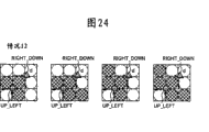
The table of Figure 28 comprises 16 contour point informations that are expressed as " xxx_yyy_zzz " or " xxx_yyy " form altogether.Partly " xxx " indication has the direction of the vector of the terminal point that is limited by point.Partly " yyy " indication has the direction of the vector of the starting point that is limited by point.UP indication upward to, DOWN indicates downward direction, RIGHT indicates to right, LEFT indicates direction left.For example, point No.01 has the upwards starting point and the vectorial starting point of vector to the right to No.03.
Partly " _ zzz " indicates the point with this assignment information from the marginal point extracting section, and is described in the marginal points information field in Figure 28.For example, _ TR indication point is the marginal point (referring to Figure 29 A) that extract on the right side (Top right) from the upper end of line element, and _ LT indication point is the marginal point (referring to Figure 29 B) that extract on the top (Left Top) from the left part of line element.
In addition, _ RB indication point is the marginal point (referring to Figure 29 C) that extracts from the bottom (RightBottom) of the right part of line element, and _ BR indication point is the marginal point (referring to Figure 29 D) that extract on the right side (Bottom Right) from the bottom of line element.
In addition, _ LB indication point is the marginal point (referring to Figure 29 B) that extracts from the bottom (LeftBottom) of the left part of line element, and _ BL indication point is the marginal point (referring to Figure 29 D) that extract in the left side (Bottom Left) from the bottom of line element.
In addition, _ RT indication point is the marginal point (referring to Figure 29 C) that extract on the top (Right Top) from the right part of line element, and _ TL indication point is the marginal point (referring to Figure 29 A) that extract in the left side (Top Left) from the upper end of line element.
Figure 30 A illustrates from the example of the point of non-marginal point part (being the non-marginal portion of line element) extraction to 30D, and the profile information of this point does not comprise " _ zzz " part.
If object pixel is a black picture element, then be used for to carry out with reference to the numerical value that the correspondence position in " numerical value " field of the contour point information shown in Figure 28 is listed from the actual treatment that the various states shown in Figure 12 to 27 extract point and assignment information according to the state of adjacent pixels.
In 30D, have mark " o " the indication black picture element of diagonal line chequer at Figure 30 A, and dashed lines labeled " o " indication white pixel.
The start point/end point position of profile vector is along the equal centre position between two pixels of main scanning direction and sub scanning direction.The two-dimensional coordinate of positive integer is represented along the location of pixels of main scanning direction and sub scanning direction.
Present embodiment uses even number remarked pixel position, and uses odd number to represent the position of starting point and terminal point.In the present embodiment, can use the coordinate expression formula of 2m * 2n positive even numbers (integer) to represent the image that constitutes by m pixel * n pixel.Present embodiment uses to have corresponding to the x coordinate of main scanning direction with corresponding to the two-dimensional coordinate system of the y coordinate of sub scanning direction.Present embodiment is expressed as the matrix of m (pixel) * n (grating) with bianry image, and wherein m and n are positive integers.In addition, (wherein i and j are the positive integers of satisfied " i≤m " and " j≤n " relation for 2i, the 2j) location of pixels of i pixel of j grating of expression.The x coordinate figure increases from left to right along main scanning direction, and the y coordinate increases from top to bottom along sub scanning direction.
Operation with reference to profile (periphery) sequence vector extraction unit 3110 between Figure 31 A to 33 explanation marginal point.
Different with U.S. Patent number 6404921, first exemplary embodiment detect four engage continuously by the marginal point of the bianry image of refinement and/or intersection point, and extract one group of independent vector corresponding as connection marginal point and/or the separate line element of intersection point or the set of closed curve with each line component.In addition, first exemplary embodiment is extracted the contour point information of distributing to each point.In addition, as conspicuous from Figure 11 to 27, first exemplary embodiment is used the process object of 3 * 3 picture element matrix patterns.But, be similar to U.S. Patent number 6404921, first exemplary embodiment is used 3 * 3 scanning windows that are made of 9 pixels that image is carried out raster scanning and is handled, and extracts point successively based on the state of the object pixel that comprises in 3 * 3 picture element matrix patterns and 8 adjacent pixels.First exemplary embodiment extract from each 3 * 3 picture element matrix pattern aspect point and the contour point information different with U.S. Patent number 6404921.
Figure 31 A illustrates according to profile (periphery) vector between the marginal point of first exemplary embodiment of the present invention to extract the process flow diagram of handling, and the CPU 519 of its usable image treating apparatus carries out.According to the vectorial processing of extracting the process flow diagram realization of handling the Figure 22 that are similar to U.S. Patent number 6404921 interior discussion of profile (periphery) between the marginal point of present embodiment.But U.S. Patent number 6404921 does not use contour point information.First exemplary embodiment is regarded contour point information as the attribute information of distributing to each point that is extracted.In addition, the point link information of each point that will extract from U.S. Patent number 6404921 of first exemplary embodiment is regarded the part of the information of each point as.
If the data layout of each contour point data has the coordinate figure that not only comprises point but also the data structure that comprises contour point data, then this processing can easily realize.
At first, in step S1, CPU 519 execute vector sequences are extracted and are handled.CPU 519 is from bianry image and the contour point information extracted vector sequence that is associated with each point.Then, the table of CPU 519 output map 31B and 31C, flows into any vector (being the terminal point identical vector of starting point of vector therewith) of this vector and any vector that flows out this vector (being the starting point identical vector of terminal point of vector therewith) at the coordinate figure of each vectorial starting point of this table indication.
In step S2, the inflow in the table shown in CPU 519 follows in Figure 31 B and the 31C and the item No. of outflow vector.CPU 519 generates the sequence vector table 3201 that illustrates in Figure 32, the combination of the contour point information of the sum of the point on the sum of the outline line that comprises in this sequence vector table indicating image, every the outline line, the x coordinate/y coordinate of each point on the outline line and each point.
In step S3, the file storage of information that CPU 519 will comprise sequence vector table 3201 via dish I/O 521 and stops sequential operation in hard disk unit 522.The vector data of the individual region that comprises in this file composing images.
Figure 33 illustrates the process flow diagram that extracts the details of handling according to the sequence vector in the step S1 of Figure 31 A of first exemplary embodiment of the present invention.
At first, in step S110, CPU 519 determines that object pixel is white pixel or black picture element.If object pixel is white pixel (NO in the step S110), then handles stream and advance to step S130.If object pixel is black picture element (YES in the step S110), then handles stream and advance to step S120.
In step S120, CPU 519 carries out based on the state of eight pixels of surrounding target pixel and handles.Hereinafter further describe the details (step S120) of the state of eight pixels handling the surrounding target pixel with reference to Figure 34.
In step S130, CPU 519 upgrades location of pixels.Then, in step S140, CPU 519 determines whether the processing of last pixel is finished.If (NO in the step S140) also do not finished in the processing to last pixel, then handle stream and return step S110 so that next object pixel is carried out above-mentioned processing.If (YES in the step S140) finished in the processing to last pixel, then handle the step S2 that stream advances to Figure 31 A.
Hereinafter extract the example of handling based on the sequence vector in state (situation 0) the description of step S1 shown in Figure 12.Object pixel (being the center pixel of Figure 12) have coordinate (2i, 2j).
At first, CPU 519 will (2i-1 2j-1) be registered as the starting point of horizontal vector.More specifically, CPU 519 stores (2i-1) in the literary name section 1231 into, the x coordinate figure of the starting point of the horizontal vector of horizontal vector profile 1230 indications in this literary name section index map 31B.Similarly, CPU 519 is stored in (2j-1) in the literary name section 1232 of y coordinate figure of starting point of this horizontal vector of indication.The source vertical vector that flows into this horizontal vector is that the current vertical vector by 1240 indications of the vertical vector counter in Figure 31 C of next-door neighbour is stored in the vector in the starting point coordinate table.The purpose vertical vector that flows out this horizontal vector is positioned at the starting point coordinate table position of current vertical vector by 1240 indications of vertical vector counter.
That is, CPU 519 with 1 and vertical vector counter 1240 in the position 1233 of inflow vector item No. field of the horizontal vector of value sums shown in being stored in Figure 31 B.In addition, CPU519 is stored in the value in the vertical vector counter 1240 position 1234 of the outflow vector item No. field of horizontal vector.
Next, CPU 519 will (2i+1 2j+1) be registered as the starting point of vertical vector.The source horizontal vector that CPU519 will flow into this vertical vector is registered as the horizontal vector that has been registered.The purpose horizontal vector that CPU 519 will flow out this vertical vector is registered as the horizontal vector of first horizontal vector storage in the starting point coordinate table that the next-door neighbour has been registered in horizontal vector.
Promptly, according to the example shown in Figure 31 C, CPU 519 is stored in field 1241 with (2i+1), and (2i-1) is stored in field 1242, currencys in the horizontal vector counter 1230 are stored in field 1243, and with 1 and horizontal vector counter 1230 in the currency sums be stored in field 1244.
Next, CPU 519 increases the content (promptly adding 1) of horizontal vertical vector 1230.Next, CPU 519 will (2i+1 2j+1) be registered as the starting point coordinate of horizontal vector.The source vertical vector that CPU519 will flow into this horizontal vector is registered as the secondary vector that has been registered.The purpose vertical vector that CPU 519 will flow out this horizontal vector is registered as the vertical vector of the next position in the starting point coordinate table that is stored in second vertical vector that has been registered.
Next, CPU 519 increases the value (promptly adding 1) of vertical vector counter 1240.Next, CPU 519 will (2i-1 2j+1) be registered as the starting point coordinate value of vertical vector.The source horizontal vector that CPU 519 will flow into this vertical vector is registered as the 3rd horizontal vector that has been registered.The purpose horizontal vector that CPU 519 will flow out this vertical vector is registered as the 4th horizontal vector that has been registered.Like this, CPU 519 increases the content (promptly adding 1) of horizontal vector counter 1230 and vertical vector counter 1240, and stops this processing.
Figure 34 is the process flow diagram that illustrates according to the details of the processing in the step S120 of Figure 33 of first exemplary embodiment of the present invention.
In step S120, CPU 519 removes register and is " 0 ".Next, in step S220, CPU 519 determines whether the state of the pixel " 0 " (being called as f (0)) in Figure 11 is black picture element (with " 1 " expression).That is, CPU 519 determines whether f (0) equals 1.If f (0) equals 1 (YES in the step S220), then handle stream and advance to step S230, wherein CPU 519 adds 1 with the content of register.If f (0) equals 0,, then handle stream and advance to step S240 if promptly the state of pixel " 0 " is white pixel (NO in the step S220).
In step S240, CPU 519 determines whether the state of the pixel " 1 " in Figure 11 is black picture element.That is, CPU 519 determines whether f (1) equals 1.If f (1) equals 1 (YES in the step S240), then handle stream and advance to step S250, wherein CPU 519 adds 2 with the content of register.If f (1) equals 0 (NO in the step S240), then handle stream and advance to step S260.
In step S260, CPU 519 determines whether the state of the pixel " 2 " in Figure 11 is black picture element.That is, CPU 519 determines whether f (2) equals 1.If f (2) equals 1 (YES in the step S260), then handle stream and advance to step S270, wherein CPU 519 adds 4 with the content of register.If f (2) equals 0 (NO in the step S260), then handle stream and advance to step S280.
In step S280, CPU 519 determines whether the state of the pixel " 3 " in Figure 11 is black picture element.That is, CPU 519 determines whether f (3) equals 1.If f (3) equals 1 (YES in the step S280), then handle stream and advance to step S290, wherein CPU 519 adds 8 with the content of register.If f (3) equals 0 (NO in the step S260), then handle stream and advance to step S300.
In step S300, CPU 519 carries out based on the value that keeps in the register (handle number) and handles.
To shown in Figure 27 (situation 15), according to the state of each pixel " 0 " in Figure 11, " 1 ", " 2 " and " 3 ", the content of register is any one in 0 to 15 as Figure 12 (situation 0).
That is, in step S300, CPU 519 extracts point that limits in Figure 12 to 27 and the contour point information that is associated.
Like this, profile (periphery) sequence vector extraction unit 3110 is carried out once complete raster scanning operation between marginal point.Therefore, profile between marginal point (periphery) sequence vector extraction unit 3110 extracts corresponding to four engaging continuously by set of the sequence vector of the independent line of marginal point that comprises in the bianry image of refinement (line chart) or intersection point or closed curve (" line element coarse contour sequence vector between marginal point ") and the contour point information that is associated of connecting input, and the output result.
Figure 32 illustrates the exemplary process result, and this result comprises from each line element being the set of the sequence vector of first profile, second profile and a profile extraction, and the contour point information that is associated with each point.
Profile (periphery) sequence vector is the exemplary record of line element coarse contour sequence vector (sequence vector that thick line is represented) and contour point information between marginal point between the marginal point that Figure 35 illustrates line chart, extract from line chart.
Figure 36 is the process flow diagram that illustrates according to the exemplary operation of core (periphery) sequence vector generation unit 3120 between the marginal point of first exemplary embodiment of the present invention.The CPU 519 of image processing apparatus realizes this processing.
In step S1000, core between marginal point (periphery) sequence vector generation unit 3120 is from profile (periphery) sequence vector between profile between marginal point (periphery) sequence vector extraction unit 3110 input marginal points.Profile between marginal point (periphery) sequence vector is the set corresponding to the sequence vector of independent lines that connects marginal point and/or intersection point or closed curve, and it comprises that whether the indication vector is from the information (assignment information) corresponding to the extracting section of marginal point (intersection point) position of line chart.The set of sequence vector is " a line element coarse contour sequence vector between marginal point ".
At step S1100, core between marginal point (periphery) sequence vector generation unit 3120 from sequence vector of profile (periphery) sequence vector input between the marginal point of step S1000 (be k profile (1≤k≤a)) in Figure 32 as current process object, this sequence vector has the data layout of Figure 32 shown in interior.Core between marginal point (periphery) sequence vector generation unit 3120 repeating step S1100 are to press ascending order input vector sequence one by one.
At step S1200, vector of core between marginal point (periphery) sequence vector generation unit 31 20 inputs is the sequence vector (sum of determining in the step S1100 of point; The point of a vector p) (q point (1≤q≤p)) as current process object.Core between marginal point (periphery) sequence vector generation unit 3120 repeating step S1200 are to press ascending order input vector one by one.
At step S1300, core between marginal point (periphery) sequence vector generation unit 3120 determines with reference to the contour point information of the point of determining in the step S1200 whether its terminal point vector or its starting point with this point identical vector identical with this point point to a left side.If the direction of vector is LEFT (YES in the step S1300), then handles stream and advance to step S1400.If the direction of vector is not LEFT (NO in the step S1300), then handles stream and advance to step S1500.
In step S1400, core between marginal point (periphery) sequence vector generation unit 3120 subtracts 1 with the y coordinate figure of point.(x y) is that (2*i, in the time of 2*j), core between marginal point (periphery) sequence vector generation unit 3120 calculates y=2*j-1 when coordinate figure.That is, core (periphery) sequence vector generation unit 3120 makes the y coordinate figure of point move the half-pixel width along sub scanning direction towards initial point between marginal point.Then, handle stream and advance to step S1600.
At step S1500, core between marginal point (periphery) sequence vector generation unit 3120 adds 1 with the y coordinate figure of point.That is, core between marginal point (periphery) sequence vector generation unit 3120 calculates y=2*j+1, so that the y coordinate figure of point moves the half-pixel width along sub scanning direction towards the direction opposite with initial point.Then, handle stream and advance to step S1600.
At step S1600, core between marginal point (periphery) sequence vector generation unit 3120 determines with reference to the contour point information of the point of determining in the step S1200 whether its terminal point vector or its starting point with this point identical vector identical with this point point to.If the direction of vector is UP (YES in the step S1600), then handles stream and advance to step S1700.If the direction of vector is not UP (NO in the step S1600), then handles stream and advance to step S1800.
In step S1700, core between marginal point (periphery) sequence vector generation unit 3120 adds 1 with the x coordinate figure of point.That is, core between marginal point (periphery) sequence vector generation unit 3120 calculates x=2*i+1, so that the x coordinate figure of point moves the half-pixel width along main scanning direction towards the direction opposite with initial point.Then, handle stream and advance to step S1900.
At step S1800, core between marginal point (periphery) sequence vector generation unit 3120 subtracts 1 with the x coordinate figure of point.That is, core between marginal point (periphery) sequence vector generation unit 3120 calculates x=2*i-1, so that the x coordinate figure of point moves the half-pixel width along main scanning direction towards initial point.Then, handle stream and advance to step S1900.
In step S1900, core between marginal point (periphery) sequence vector generation unit 3120 determines whether all point in the sequence vector of determining in the step S1100 to have been finished the processing of step S1200 to S1800.If finished processing (YES in the step S1900), advanced to step S2000 at processing stream to all point.If do not finish processing to all point (NO in the step S1900), handle then that stream returns step S1200 so that the next vector in the sequence vector is handled.
In step S2000, core between marginal point (periphery) sequence vector generation unit 3120 determines whether all sequence vectors in the line element coarse contour sequence vector between the marginal point of importing in the step S1000 to have been finished above-mentioned processing.If do not finish processing (YES in the step S2000), then handle stream and advance to step S2100 to all sequence vectors.If do not finish processing to all point (NO in the step S2000), handle then that stream returns step S1100 so that to the processing of next sequence vector execution in step S1200 to S2000.
In step S2100, the result of line element coarse contour sequence vector between the marginal point in core between marginal point (periphery) the sequence vector generation unit 3120 output step S1000.
The numerical value of the Value field of determining to be based on the above-mentioned contour point information that illustrates in Figure 28 in step S1300 or the step S1600 is carried out.Therefore, highest significant position (MSB) is represented in position 7 if the least significant bit (LSB) (LSB) of the numerical value that is represented as binary value is represented in position 0, then core (periphery) sequence vector generation unit 3120 is checked position 2 (being " (0) (1) " the to the right left field Figure 28 in) between marginal point in step S1300, and if 2 be 1 then the direction of vector is LEFT.In step S1600, core between marginal point (periphery) sequence vector generation unit 3120 is checked position 3 (" upwards (0) (1) " the downwards fields in Figure 28), and if position 3 be 0 then the direction of vector is UP.
Like this, core (periphery) sequence vector generation unit 3120 is imported profile (periphery) sequence vector between marginal points from profile between marginal point (periphery) sequence vector extraction unit 3110 between marginal point.Then, core (periphery) sequence vector generation unit 3120 will constitute width that profile (periphery) vectorial each vectorial position meticulous adjusting with a pixel wide equal a half-pix with reference to assignment information along suitable direction according to pre-defined rule between marginal point.Therefore, between marginal point core (periphery) sequence vector generation unit 3120 can to generate line width be core (periphery) sequence vector between 0 marginal point.For example, the data layout shown in core (periphery) sequence vector can use in Figure 32 between the marginal point of generation is represented.Core (periphery) sequence vector between the marginal point of core between marginal point (periphery) sequence vector generation unit 3120 is exportable data layout shown in having in Figure 32.
It is core (periphery) sequence vector (that is, using the sequence vector of the fine rule of the location of pixels that connects the input bianry image) between 0 marginal point that Figure 35 illustrates core coarse contour sequence vector (sequence vector that promptly uses thick line to represent) and line width between marginal point.
Next, the exemplary operation of auxiliary vector introducing (periphery) sequence vector generation unit 3210 between marginal point is described.
Auxiliary vector introducing (periphery) sequence vector generation unit 3210 assists vectorial (periphery) sequence vector smoothing unit 3220 of introducing to carry out the auxiliary vector of smoothing (approximation to function) processing insertion before between marginal point between marginal point.More specifically, auxiliary vector is introduced (periphery) sequence vector generation unit 3210 and is inserted auxiliary vector between marginal point, thereby the marginal point part can be saved and is marginal point (being the anchor point of Bezier).This processing can prevent the vector and another vectorial combination corresponding to the marginal point part, and can prevent that the position of any marginal point when auxiliary vector introducing (periphery) sequence vector smoothing unit 3220 execution smoothings (approximation to function) are handled between marginal point from becoming unclear.
In addition, smoothedization sequence vector identification (non-periphery) unit 3230 is introduced (periphery) sequence vector based on auxiliary vector between the marginal point of smoothedization (approximation to function) of introducing 3220 inputs of (periphery) sequence vector smoothing unit from auxiliary vector between marginal point and is generated initial/terminating edge dot information between marginal point.More specifically, the vector that is used as terminating edge point as the vector sum of start edge point is discerned in smoothedization sequence vector identification (non-periphery) unit 3230 between marginal point from each smoothedization (periphery) vector, and be that each smoothedization (periphery) vector generates initial/terminating edge dot information, this information can be used for generating the non-peripheral sequence vector that only the start edge point is connected to terminating edge point.
In first exemplary embodiment, the configuration of auxiliary vector introducing (periphery) sequence vector smoothing unit 3220 is similar to described configuration in the U.S. Patent Application Publication No. US2005/0238244 A1 between marginal point.This configuration makes for may using the smoothing unit that the vector of whole thinning lines image is carried out smoothing also not by the profile of the bianry image of refinement (profile) vector.
According to U.S. Patent Application Publication No. US 2005/0238244 A1, the outline data (rough outline data) that comprises input and be made of level and the vertical vector from the data extract of scale-of-two raster image that replace is handled in vector smoothing (approximation to function), line segments extraction tangent line line segment from coarse contour, from the tangent line line segment that extracts, extract anchor point, and with the combination of 2 rank or 3 rank Beziers and straight line or carried out 2 approximate rank of Bezier or 3 rank Beziers replacements are connected one group of line segment of the anchor point that extracts.
The method that is used for based on the anchor point of determining one group of point between two anchor points being carried out approximation to function is the basic function approximation method.Even when the point minuend between two anchor points was approximately 2 rank or 3 rank Beziers or straight line, the position of each anchor point (coordinate figure) can not change yet.
Therefore, auxiliary vector is introduced (periphery) sequence vector generation unit 3210 marginal point of core between marginal point (periphery) sequence vector is appointed as start edge point and another marginal point is appointed as the terminating edge point between marginal point, and between start edge point and terminating edge point, insert auxiliary vector (auxiliary point), so that start edge point and terminating edge point all become anchor point.
According to U.S. Patent Application Publication No. US 2005/0238244 A1, represent the extraction conditions of vector of tangent line line segment as follows:
(1) two vectors just settling before object vector and afterwards have reverse direction;
(2) length L 1 of the vector adjacent with the primary tangent line segment that is extracted satisfies relation " L1 〉=θ
4"; And
(3) vector length L2 satisfies relation " L2 〉=θ
5".
In addition, the extraction of anchor point comprises the new point of extraction from the tangent line line segment that extracts, and the point that each extracts is appointed as anchor point.Can be from two anchor points of two edge extractings of tangent line line segment.If two anchor points that extract are mutually the same, then can only extract an anchor point.
If extract two anchor points, then the part between two anchor points is appointed as the straight line on the object automatically.As the method that is used for extracting from a marginal point of tangent line line segment anchor point, if the adjacency vector of object vector (target tangent line line segment) is the tangent line line segment, then the marginal point of adjacency vector is an anchor point.
Therefore, auxiliary vector is introduced (periphery) sequence vector generation unit 3210 marginal point of core between marginal point (periphery) sequence vector is appointed as the start edge point between marginal point, and another marginal point is appointed as the terminating edge point, and insert auxiliary point so that start edge point and terminating edge point all become anchor point.
Figure 37 A illustrates and is used for just will becoming the marginal point P of start edge point
0Insert auxiliary point P before
-1Illustrative methods.
Auxiliary vectorial V
-1Comprise auxiliary point P
-1As starting point.Vector V
1Comprise just at marginal point P
1Point P afterwards
0As starting point.So two vectorial V
-1And V
1Has reverse direction.In other words, three vectorial V that illustrate in Figure 37 A
-1, V
0And V
1Can satisfy the tangent line line segments extraction condition (1) of above-mentioned U.S. Patent Application Publication No. US 2005/0238244 A1.Therefore, vectorial V
0Become the tangent line line segment.
In addition, if from auxiliary point P
-1The auxiliary vectorial V of beginning
-1Length with enough tangent line line segments extraction conditions (3) that satisfies above-mentioned U.S. Patent Application Publication No. US 2005/0238244 A1, then auxiliary vectorial V
-1Also become the tangent line line segment.That is auxiliary vectorial V,
-1With vectorial V
0All become the tangent line line segment.As a result, marginal point P
0(being about to become the point of start edge point) becomes anchor point (that is, if the adjacency vector of object vector (being target tangent line line segment) is the tangent line line segment, then the marginal point of adjacency vector becomes anchor point) according to the condition in the above-mentioned anchor point extraction method.
Figure 37 B illustrates and is used for just will becoming the marginal point P of terminating edge point
nInsert auxiliary point P afterwards
N+1Illustrative methods.
Auxiliary vectorial V
nComprise auxiliary point P
N+1As terminal point.Vector V
N-2Comprise point P
N-1As terminal point.So two vectorial V
nAnd V
N-2Has reverse direction.In other words, three vectorial V that illustrate in Figure 37 B
N-2, V
N-1And V
nCan satisfy the tangent line line segments extraction condition (1) of above-mentioned U.S. Patent Application Publication No. US 2005/0238244 A1.Therefore, vectorial V
N-1Become the tangent line line segment.In addition, if with auxiliary point P
N+1The auxiliary vectorial V that finishes
nLength with enough tangent line line segments extraction conditions (3) that satisfies above-mentioned U.S. Patent Application Publication No. US 2005/0238244 A1, then auxiliary vectorial V
nAlso become the tangent line line segment.
That is auxiliary vectorial V,
nWith vectorial V
N-1All become the tangent line line segment.As a result, marginal point P
n(that is, will become the point of terminating edge point) becomes anchor point (that is, if the adjacency vector of object vector (being target tangent line line segment) is the tangent line line segment, then the marginal point of adjacency vector becomes anchor point) according to the condition in the above-mentioned anchor point extraction method.
Like this, auxiliary vector is introduced (periphery) sequence vector generation unit 3210 and is determined to put up with to be inserted in the point before the start edge point and to put up with and be inserted in terminating edge point point afterwards between marginal point, thereby start edge point and terminating edge point become anchor point.Then, auxiliary vector is introduced (periphery) sequence vector generation unit 3210 and is generated by continuous joint level that connects this insertion point and the point sequence that vertical vector constitutes between marginal point, it comprise the intrinsic point sequence that extends to this terminating edge point from this start edge point with increase newly extend to the part of this terminating edge point via this insertion point from this start edge point.In addition, auxiliary vector is introduced (periphery) sequence vector generation unit 3210 and is generated initial/terminating edge dot information, start edge point and terminating edge point in this information Recognition point sequence between marginal point.
In first exemplary embodiment, initial/terminating edge dot information comprises the coordinate figure of start edge point and the coordinate figure of terminating edge point.
Figure 38 illustrates the process flow diagram of introducing the exemplary operation of (periphery) sequence vector generation unit 3210 according to auxiliary vector between the marginal point of first exemplary embodiment of the present invention.The CPU 519 of image processing apparatus realizes this processing.
At first, at step S3000, to introduce (periphery) sequence vector generation unit 3210 be core (periphery) sequence vector between 0 marginal point from core between marginal point (periphery) sequence vector generation unit 3120 incoming line width to auxiliary vector between marginal point.
At step S3100, a definite successively sequence vector core (periphery) sequence vector is imported between the marginal point of auxiliary vector introducing (periphery) sequence vector generation unit 3210 in step S3000 between marginal point (k point in Figure 32 (1≤k≤a)) be current process object, the data layout shown in this sequence vector has in Figure 32.
At step S3200, to introduce vector of (periphery) sequence vector generation unit 3210 inputs be that (sum of point: the point of a vector p) (q point (1≤q≤p)) is as process object for the sequence vector determined in the step S3100 to auxiliary vector between marginal point.When the processing of step S3200 comprises the processing of each execution in step S3200, pressed ascending order from first o'clock to p and select process object successively, up in step S3300, detecting the start edge point.
At step S3300, auxiliary vectorial (periphery) sequence vector generation unit 3210 of introducing determines with reference to the contour point information of the point of determining in the step S3200 whether point is to become the vector of start edge point between marginal point.If point is the vector (YES in the step S3300) that will become start edge point, then handles stream and advance to step S3600.If point is not the vector (NO in the step S3300) that will become start edge point, handles stream and advance to step S3400.
Step S3300 determines and can carry out with reference to the contour point information of point.More specifically, auxiliary vector is introduced (periphery) sequence vector generation unit 3210 and is determined that whether point are any one among UP_RIGHT_LT (03H), DOWN_LEFT_RB (0FH), LEFT_UP_BL (17H) and the RIGHT_DOWN_TR (1BH) in Figure 28 between marginal point.This processing can be by position 1 in the Value field of checking Figure 28 and position 0 numerical value whether all be 1 to realize.
At step S3400, the processing that auxiliary vector introducing (periphery) sequence vector generation unit 3210 determines whether to finish to institute's directed quantity of a sequence vector in core (periphery) the sequence vector input between the marginal point in the step S3100 between marginal point.If also do not finish processing (NO among the step S3400), then handle stream and return step S3200 with to determining in the next vectorial execution in step S330 in the sequence vector institute's directed quantity of a sequence vector.If finished the processing (YES in the step S3400) to institute's directed quantity of a sequence vector, but then the interior sequence vector input of determining step S3100 does not comprise start edge point candidate.Handle stream and advance to step S3500.
At step S3500, auxiliary vector introducing (periphery) sequence vector generation unit 3210 is that sequence vector distributes a closed loop mark between marginal point.Closed loop mark indication sequence vector is the closed loop that does not comprise marginal point.Auxiliary vector is introduced the directly sequential vector of this sequence vector of output of (periphery) sequence vector generation unit 3210 between marginal point.
Figure 39 A illustrates the data layout of sequence vector, is to comprise the process object of v vector altogether according to s sequence vector of this data layout.Two closed loop marks have the marginal point coordinate of (1 ,-1), and it is assigned to initial/terminating edge dot information, although these coordinate figures do not exist.When the finishing dealing with of step S3500, handle stream and advance to step S4200.
At step S3600, auxiliary vector is introduced (periphery) sequence vector generation unit 3210 point is registered as the start edge point between marginal point, and exports this point as a vector that extends to this terminating edge point from this start edge point.Then, handle stream and advance to step S3700.
At step S3700, be similar to step S3200, to introduce vector of (periphery) sequence vector generation unit 3210 inputs be that (sum of point: the point of a vector p) (q point (1≤q≤p)) is as process object for the sequence vector determined in the step S3100 to auxiliary vector between marginal point.When the processing of step S3700 comprised the processing of each execution in step S3700, the point of determining in the step S3200 was pressed ascending order towards p and is selected process object successively, up to detect the terminating edge point in step S3800.Then, handle stream and advance to step S3800.
At step S3800, auxiliary vectorial (periphery) sequence vector generation unit 3210 of introducing determines with reference to the contour point information of the point of determining in the step S3700 whether point is to become the vector of terminating edge point between marginal point.If point is the vector (YES in the step S3800) that will become terminating edge point, then handles stream and advance to step S4000.If point is not the vector (NO in the step S3800) that will become terminating edge point, handles stream and advance to step S3900.
Step S4000 determines and can carry out with reference to the contour point information of point.More specifically, auxiliary vector is introduced (periphery) sequence vector generation unit 3210 and is determined that whether point are any one among UP_RIGHT_TL (01H), DOWN_LEFT_BR (0DH), LEFT_UP_LB (15H) and the RIGHT_DOWN_RT (19H) in Figure 28 between marginal point.This processing can be 0 and 1 to realize by the numerical value of position 1 in the Value field of checking Figure 28 and position 0.
At step S3900, auxiliary vector is introduced (periphery) sequence vector generation unit 3210 output point as a vector that extends to this terminating edge point from this start edge point between marginal point.Then, handle stream and return step S3700.
At step S4000, auxiliary vector is introduced (periphery) sequence vector generation unit 3210 point is registered as the terminating edge point between marginal point, and exports this point as a vector that extends to this terminating edge point from this start edge point.Then, handle stream and advance to step S4100.
At step S4100,3210 generations of auxiliary vector introducing (periphery) sequence vector generation unit will be by the auxiliary vector of the order of inserting between terminating edge point and start edge point between marginal point, because the start edge point of sequence vector and terminating edge point are determined, and the sequential vector of connection start edge point and terminating edge point is output.Hereinafter with reference to the details of the processing of Figure 40 in the 42 description of step S4100.Finish when the processing of step S4100, then handle stream and advance to step S4200.
At step S4200, auxiliary vector introducing (periphery) sequence vector generation unit 3210 determines whether the processing of all sequence vectors in core (periphery) the sequence vector input between the marginal point in the step S300 are finished between marginal point.If (YES in the step S4200) finished in the processing to all sequence vectors, then handle stream and advance to step S4300.If also do not finish processing to all sequence vectors (NO in the step S4200), then handle stream and return step S3100 and think the processing of next sequence vector execution in step S3200 to S4200.
At step S4300, auxiliary vector is introduced the result of core (periphery) sequence vector between the interior marginal point of (periphery) sequence vector generation unit 3210 output step S3000 between marginal point.
Figure 39 B illustrates when start edge point and the terminating edge point of determining sequence vector (being process object), and except the sequential vector that connects start edge point and terminating edge point, also generate the order to be inserted between this terminating edge point and the start edge point and assist when vectorial, with the output example of the sequence vector that is output.
In Figure 39 B, u sequence vector is process object, it comprises the sequential vector of t altogether that constitutes the sequence vector that connects start edge point (being first point) and terminating edge point (i.e. t point), and will be inserted in the auxiliary vector of r altogether order between terminating edge point and the start edge point.
Figure 40 is the process flow diagram that illustrates according to the details of the processing in the step S4100 of Figure 38 of first exemplary embodiment of the present invention.More specifically, at start edge point and the terminating edge point of determining sequence vector, and under the situation of the sequential vector of output this start edge point of connection and terminating edge point, auxiliary vector introducing (periphery) sequence vector generation unit 3210 generates the order that will be inserted between terminating edge point and the start edge point and assists vector between marginal point.
In step S4110, as reference Figure 37 A explanation, auxiliary vector introducing (periphery) sequence vector generation unit 3210 calculates to put up with and is inserted in marginal point P between marginal point
0Auxiliary point P before
-1Coordinate figure, this marginal point will be the start edge point.That is, auxiliary vector introducing (periphery) sequence vector generation unit 3210 is determined from auxiliary point P between marginal point
-1The auxiliary vectorial V of beginning
-1Direction so that be inserted in marginal point P from putting up with
0Point P afterwards
1The vectorial V of beginning
1Direction opposite.In addition, auxiliary vector is introduced (periphery) sequence vector generation unit 3210 definite auxiliary vectorial V between marginal point
-1Length so that satisfy the tangent line line segments extraction condition (3) of above-mentioned U.S. Patent Application Publication No. US 2005/0238244 A1.For example, auxiliary vectorial V
-1Length setting be the length that is equal to or greater than ten pixels.
At step S4120, as reference Figure 37 B explanation, auxiliary vector introducing (periphery) sequence vector generation unit 3210 calculates to put up with and is inserted in marginal point P between marginal point
nAuxiliary point P afterwards
N+1Coordinate figure, this marginal point will be the terminating edge point.That is, auxiliary vector introducing (periphery) sequence vector generation unit 3210 is determined with auxiliary point P between marginal point
N+1The auxiliary vectorial V that finishes
nDirection so that with point P
N-1The vectorial V that finishes
N-2Direction opposite.In addition, auxiliary vector is introduced (periphery) sequence vector generation unit 3210 definite auxiliary vectorial V between marginal point
nLength so that satisfy the tangent line line segments extraction condition (3) of above-mentioned U.S. Patent Application Publication No. US2005/0238244 A1.For example, auxiliary vectorial V
nLength setting be the length that is equal to or greater than ten pixels.
At step S4130, it is definite from auxiliary point P that auxiliary vector is introduced (periphery) sequence vector generation unit 3210 between marginal point
-1The auxiliary vectorial V of beginning
-1With with auxiliary point P
N+1The auxiliary vectorial V that finishes
nAll be horizontal vector or vertical vector.If auxiliary vectorial V
-1And V
nSatisfy this condition (YES in the step S4130), then handle stream and advance to step S4110.If auxiliary vectorial V
-1And V
nDo not satisfy this condition (NO in the step S4130), then handle stream and advance to step S4160.
Figure 41 is illustrated in the step S4140 (promptly as auxiliary vectorial V relatively
-1And V
nWhen being two horizontal vectors or two vertical vectors) exemplary process carried out.At step S4140, auxiliary vector is introduced 3210 calculating of (periphery) sequence vector generation unit and is followed the first auxiliary point P closely between marginal point
N+1The second auxiliary point P afterwards
N+2More specifically, auxiliary vector introducing (periphery) sequence vector generation unit 3210 is determined from auxiliary point P between marginal point
N+1Beginning and with auxiliary point P
N+2The vectorial V that finishes
N-1, so that satisfy the tangent line line segments extraction condition (3) of above-mentioned U.S. Patent Application Publication No. US 2005/0238244 A1.With the first auxiliary point P
N+1Compare the second auxiliary point P
N+2The position away from auxiliary point P
-1For example, auxiliary vectorial V
N+2Length setting be the length that is equal to or greater than ten pixels.
At step S4150, auxiliary vector is introduced 3210 calculating of (periphery) sequence vector generation unit and is followed the second auxiliary point P closely between marginal point
N+2The 3rd auxiliary point P afterwards
N+3More specifically, auxiliary vector is introduced (periphery) sequence vector generation unit 3210 the definite the 3rd auxiliary point P between marginal point
N+3, so that two auxiliary point P
N+2And P
-1Can be connected with vertical vector with the level that replaces.The 3rd auxiliary point P
N+3, proximate edge point P
0The location, but auxiliary point of midfeather (is P
-1).After the said sequence processing has been finished, handle the interior step S4200 of process flow diagram that stream returns Figure 38.
Figure 42 illustrates in the step S4160 (promptly as auxiliary vectorial V relatively
-1And V
nWhen being the combination of horizontal vector and vertical vector) exemplary process carried out.At step S4160, auxiliary vector is introduced 3210 calculating of (periphery) sequence vector generation unit and is followed the first auxiliary point P closely between marginal point
N+1The second auxiliary point P afterwards
N+2More specifically, auxiliary vector introducing (periphery) sequence vector generation unit 3210 is determined from auxiliary point P between marginal point
N+1Beginning and with auxiliary point P
N+2The vectorial V that finishes
N+1, so that satisfy the tangent line line segments extraction condition (3) of above-mentioned U.S. Patent Application Publication No. US 2005/0238244 A1.With the first auxiliary point P
N+1Compare the second auxiliary point P
N+2The position away from auxiliary point P
-1For example, auxiliary vectorial V
N+1Length setting be the length that is equal to or greater than ten pixels.
At step S4170, auxiliary vector is introduced 3210 calculating of (periphery) sequence vector generation unit and is followed the second auxiliary point P closely between marginal point
N+2The 3rd auxiliary point P afterwards
N+3More specifically, auxiliary vector introducing (periphery) sequence vector generation unit 3210 is determined from auxiliary point P between marginal point
N+2Beginning and with auxiliary point P
N+3The vectorial V that finishes
N+2, so that satisfy the tangent line line segments extraction condition (3) of above-mentioned U.S. Patent Application Publication No. US 2005/0238244 A1.With the second auxiliary point P
N+2Compare the 3rd auxiliary point P
N+3The position away from auxiliary point P
-1For example, auxiliary vectorial V
N+3Length setting be the length that is equal to or greater than ten pixels.
At step S4180, auxiliary vector is introduced 3210 calculating of (periphery) sequence vector generation unit and is followed the 3rd auxiliary point P closely between marginal point
N+3The 4th auxiliary point P afterwards
N+4More specifically, auxiliary vector is introduced (periphery) sequence vector generation unit 3210 the definite the 4th auxiliary point P between marginal point
N+4, so that two auxiliary point P
N+3And P
-1Can be connected with vertical vector with the level that replaces.The 4th auxiliary point P
N+4Proximate edge point P
0The location, but auxiliary point of midfeather (is P
-1).After the said sequence processing has been finished, handle the interior step S4200 of process flow diagram that stream returns Figure 38.
As mentioned above, auxiliary vector is introduced (periphery) sequence vector generation unit 3210 from core (periphery) sequence vector between core between marginal point (periphery) sequence vector generation unit 3210 input marginal points between marginal point.Then, auxiliary vector is introduced (periphery) sequence vector generation unit 3210 and is inserted auxiliary vector between marginal point, to prevent the vector and another vectorial combination corresponding to the marginal point part.In other words, this processing can prevent that the position of any marginal point becomes unclear when auxiliary vector between marginal point is introduced 3220 execution smoothings (approximation to function) processing of (periphery) sequence vector smoothing unit.That is, auxiliary vector introducing (periphery) sequence vector generation unit 3210 inserts auxiliary vector between marginal point, so that the marginal point part can be retained as marginal point (being the anchor point of Bezier), and auxiliary vector is introduced (periphery) sequence vector between the generation marginal point.
In addition, auxiliary vector is introduced (periphery) sequence vector generation unit 3210 and is introduced the initial/terminating edge dot information of (periphery) sequence vector generation indication corresponding to the vector of marginal point part for auxiliary vector between each auxiliary vectorial marginal point of introducing between marginal point.Present embodiment uses the result of the data layout output generation that is similar to Figure 32.In the case, each the outline data part that replaces Figure 32 with the sequence vector data shown in Figure 39 A or Figure 39 B.
As mentioned above, the configuration of auxiliary vector introducing (periphery) sequence vector smoothing unit 3220 is similar to described configuration in U.S. Patent Application Publication No. US 2005/0238244 A1 between marginal point.Auxiliary vector is introduced between the marginal point that (periphery) sequence vector smoothing unit 3220 generates smoothedization (approximation to function) auxiliary vector and is introduced (periphery) sequence vector between marginal point, and it is included in part corresponding to the marginal point part and is saved each (periphery) vector into smoothedization (approximation to function) under the situation of marginal point.
Auxiliary vector is introduced (periphery) sequence vector and is outputed to smoothedization sequence vector identification (non-periphery) unit 3230 between marginal point between the marginal point of smoothedization (approximation to function) that auxiliary vector introducing (periphery) sequence vector smoothing unit 3220 will generate between marginal point.In addition, the auxiliary vectorial initial/terminating edge dot information of (periphery) sequence vector smoothing unit 3220 auxiliary vector between marginal point being introduced 3210 generations of (periphery) sequence vector generation unit of introducing outputs to smoothedization sequence vector identification (non-periphery) unit 3230 between marginal point between marginal point.
(periphery) sequence vector is introduced from auxiliary vector between the marginal point of auxiliary vector introducing (periphery) sequence vector smoothing unit 3220 smoothedization of input (approximation to function) between marginal point in smoothedization sequence vector identification (non-periphery) unit 3230 between marginal point.In addition, the initial/terminating edge dot information of (periphery) sequence vector generation unit 3210 inputs is introduced from auxiliary vector between marginal point in smoothedization sequence vector identification (non-periphery) unit 3230 between marginal point.
Then, smoothedization sequence vector identification (non-periphery) unit 3230 compares each interior vectorial coordinate figure of sequence vector of discerning each smoothedization (approximation to function) between marginal point by the coordinate figure with the point that is used as start edge point and terminating edge point.Smoothedization sequence vector identification (non-periphery) unit 3230 generation connection start edge points and terminating edge point are to form the non-peripheral sequence vector of the sequence vector of smoothedization (non-periphery) between marginal point between marginal point.Smoothedization sequence vector identification (non-periphery) unit 3230 outputs to individual region vector generation unit 40 with the sequence vector of smoothedization between marginal point (non-periphery) between marginal point.
Although whether indicate each point is that the attribute information of anchor point is attached to each point, the result that generates can use with Figure 32 in shown in data layout similar data form represent.In the case, the start edge of identification point is first point.The terminating edge point is last point of same line element vector.
That is, first outline portion of Figure 32 is the data division of first line element.The start edge point that first point is first line element.B point is the terminating edge point of first line element.Present embodiment uses this data layout output result.
Like this, the step S50 in the process flow diagram of Figure 10 can be followed successively by vector between each boundary line image generation marginal point that connects an intersection point and another intersection point to the processing of S80.When generating the finishing dealing with of vector between marginal points for all boundary lines, in step S100, carry out the processing that generates the individual region vector.
That is, as shown in figure 43, if there is the boundary line of any connection intersection point, then present embodiment generates as Figure 44 A successively to vector between the marginal point of an intersection point of the connection shown in the 44H and another intersection point.
Figure 45 illustrates and comprises the image that is subjected to all boundary lines that the vector generation is handled between marginal point.Figure 46 illustrates the original edge point image partly of the sequence vector of smoothedization (non-periphery) between boundary line image shown in comprising in Figure 45 and marginal point.
Even after the processing of S80 had been finished, the intersection point that extracts among the step S30 still remained unchanged with each interior intersection point of the interior boundary line image that is connected intersection point that generates of step S50 at step S50.The position of each intersection point and the relation of the position between the intersection point can be saved and be the position of the marginal point of the sequence vector of smoothedization between marginal point (non-periphery) and position relation.Like this, the intersection point that extracts in the step S30 in the processing of S80 at step S50 can be processed as marginal point always.
At step S100, individual region vector generation unit 40 is carried out the individual region vector and is generated processing.More specifically, vector information and colouring information convert each zone to the zone vector to individual region vector generation unit 40 between each the regional marginal point that obtains based on being handled by area dividing, and this zone vector comprises sequence vector and internal color thereof between the marginal point of peripheral minuend approximate (smoothing).
As mentioned above, zone boundary sequence vector recognition unit 410 and area attribute allocation units 420 constitute individual region vector generation unit 40.
Figure 47 illustrates the process flow diagram that generates the details of handling according to the vector of the individual region among the step S100 of Figure 10 of first exemplary embodiment of the present invention.
At step S1010, zone boundary sequence vector recognition unit 410 input target area numbers.That is any one area code in the zone that in step S12, obtains of zone boundary sequence vector recognition unit 410 input.For example, zone boundary sequence vector recognition unit 410 can be with reference to region list shown in Figure 2 201 each regional area code of input, and this region list is indicated each regional area code and each regional colouring information (attribute information).As mentioned above, RAM 520 is stored in the region list 201 that step S13 generates.
At step S1020, zone boundary sequence vector recognition unit 410 is imported relevant intersection point (that is marginal point: the intersection point relevant with the target area) with reference to intersection point table 601 input of the Fig. 6 that generates in the step S31 with the area code in the step S1010.For example,, then exist in three intersection point C:(22 of inclusion region number 2 in the neighboring region number field of intersection point table 601,40 if the area code input in the step S1010 is 2), E:(38,40) and F:(44,24).
In step S1030, auxiliary vector is introduced and is discerned the sequence vector (zone boundary sequence vector) that marginal point equals the intersection point input in the step S1020 in (periphery) sequence vector between the marginal point that zone boundary sequence vector recognition unit 410 generates from step S70.If vector data has the data layout of the data layout shown in being similar in Figure 32, then the processing in the step S1030 can by last that check first point of represent start edge point and represent terminating edge point whether put with step S1020 in consistent realization of coordinate figure of the intersection point that extracts.
In the vector data that data in the intersection point table 601 of Fig. 6 are represented vector between the marginal point of three minuends approximate (smoothing) is identified as target area and zone boundary sequence vector from Figure 46.Sequence vector is the sequence vector (obtaining from Figure 43 (1)) of tie point F and C between the marginal point of first minuend approximate (smoothing).Sequence vector is the sequence vector (obtaining from Figure 43 (2)) of tie point C and E between the marginal point of second minuend approximate (smoothing).Sequence vector is the sequence vector (obtaining from Figure 43 (3)) of tie point E and F between the marginal point of the 3rd minuend approximate (smoothing).
In step S1040, zone boundary sequence vector recognition unit 410 distributes corresponding field color information (attribute information) for the zone boundary sequence vector of the target area identified in the step S1030.The processing of step S1040 comprises with reference to each the regional area code of indication shown in the figure 2 and the region list 201 of each regional colouring information (attribute information), obtain colouring information (attribute information), and this attribute information is distributed to the zone boundary sequence vector of target area corresponding to the zone of the input of the area code in the step S1010.
In step S1050, zone boundary sequence vector recognition unit 410 determines whether the All Ranges number have been finished the processing of step S1010 to S1040.If also the All Ranges number is not finished processing (NO in the step S1050), then handles stream and return step S1010.If the All Ranges number is finished processing (YES in the step S1050), then the individual region vector of the step S100 in the process flow diagram of zone boundary sequence vector recognition unit 410 termination Figure 10 generates and handles.
For example, determining in the step S1050 comprises whether inspection finishes processing to the All Ranges numbers in the region list 201 of Fig. 2, whether finished promptly that first data in the region list 201 begin and with the processing of last ED.
Like this, first exemplary embodiment can realize being used for generating the sequential processes of the vector of representing coloured image (especially instructional images).
Figure 48 illustrates the image that the zone vector in each zone of sequence vector between the marginal point that comprises peripheral minuend approximate (smoothing) that obtains in the step S100 and internal color thereof reproduces.
Hereinafter will describe area dividing processing, frontier point extraction processing and intersection point in detail and extract processing.
<area dividing is handled 〉
Figure 49 is the process flow diagram that the details of handling according to the area dividing in the step S12 of first exemplary embodiment of the present invention is shown.
At step S1201, the processing of trooping is carried out in area dividing unit 121 on the process object image.The processing of step S1201 comprises from being generated first by the initial pixel of raster scanning troops, and based on the next pixel of the feature calculation of pixel with respect to all deviations of trooping.If deviation is low, then pixel has similar characteristics with trooping.That is, can determine that pixel is identical with trooping.
(Ri, Gi Bi) represent the feature of this pixel to the pixel value of pixel i.(Rc, Gc Bc) represent the feature of this pixel to belong to the average pixel value of all pixels of the c that troops.For example, deviation equals the Euclidean distance on color space between the eigenwert of the eigenwert of pixel i and the c that troops

Although present embodiment uses rgb value in the calculating of deviation, but the information of another color space or with the irrelevant information of the color also characteristic quantity of represent pixel.The processing of step 1201 comprises that registration makes the number of trooping of deviate minimum, and deviate and predetermined threshold are compared.If deviate is less than threshold value, then object pixel belongs to trooping of registration.If deviate is equal to or greater than threshold value, then generate new trooping based on object pixel.Above-mentioned processing repeats, up to the processing of finishing all pixels.
At step S1202, area dividing unit 121 is based on the result execution area integration processing of trooping.Regional Integration is handled and is comprised the desired value of importing the number of representing separated region, to current number count of trooping, and troop number and the desired value that relatively are counted.In the present embodiment, can under the situation of the quantity of the color of considering to be separated, determine desired value.If current quantity of trooping is equal to or greater than desired value, then area dividing unit 121 is integrated and is trooped.Regional Integration is handled and is comprised the deviate of calculating between trooping, and two integration of trooping that will have minimum deviate.Regional Integration is handled and is repeated, and is less than desired value up to current quantity of trooping.
At step S1203, area dividing unit 121 is carried out noise region based on the Regional Integration result and is determined to handle.Noise region determines that processing comprises marked region division result, and calculates the size of each marked region.The quantity of the pixel that the size of marked region equals to comprise in the subject area.If the size of marked region is less than threshold value, then area dividing unit 121 determines that this zone is a noise region.
At step S1204, each pixel in the 121 calculating noise zones, area dividing unit is with respect to the deviation of neighboring region, and the execution noise region is handled again so that the process object pixel belongs to the zone with minimum deflection.Noise region determines that processing repeats, up to all marked regions are finished processing.The graphics field that is obtained by the area dividing of file and picture can be compressed before being stored.Definite processing of above-mentioned noise region and noise region are handled again and can be removed the noise that generates in the compression process effectively.
As mentioned above, area dividing unit 121 can be divided into coloured image a plurality of zones that engage continuously on image.Each zone has identical or consistent feature (deviate with the threshold value of being not less than).
<frontier point extracts to be handled 〉
Hereinafter with reference to Fig. 3 describe that horizontal boundary point in the step S21 extract to be handled in detail, vertical boundary point in the step S23 extract handle and step S25 in the diagonal line frontier point extract processing.
Frontier point extracts to handle and comprises along continuous straight runs (→) scanning area division result, and represents the pixel on two borders between the zone as the horizontal boundary point in extraction on every horizontal scanning line.Fig. 3 illustrates the example images in inclusion region 1 (background), zone 2, zone 3,5 five zones in zone 4 and zone.
As shown in Figure 3, the horizontal scanning operation detection on the 10th row changes into 2 at this some place area code from 1 to some B.Detected some B is registered as the horizontal boundary point.Similar, the horizontal scanning operation detection on the 14th row is to some A, and it is registered as the horizontal boundary point.In addition, the horizontal scanning operation detects a C in succession on the 22nd row, detects an E on the 38th row, detects a F on the 44th row, detects a H and I on the 64th row, and they all are registered as the horizontal boundary point.
Frontier point extracts to handle and comprises that vertically (↓) scanning area is divided the result, and represents the pixel on two borders between the zone as the diagonal line frontier point in extraction on every vertical scan line.
As shown in Figure 3, the vertical scanning operation lists the 10th in succession and detects a D, list the 15th and to detect an A, list the 20th and to detect a B, list the 24th and to detect a F, list the 40th and to detect an E and C, list to detect a H and list the 66th the 58th and detect an I, they all are registered as the vertical boundary point.
In addition, frontier point extracts to handle and comprises along diagonal scanning area division result, and extracts on every diagonal line sweep trace and represent the pixel on two borders between the zone as the horizontal boundary point.
As shown in Figure 3, the diagonal line scan operation lists at the 14th row and the 15th and detects an A, changes into 2 at this some place area code from 1.Detected some A is registered as the diagonal line frontier point.Similarly, the diagonal line scan operation detects a B, J, C, K, E, G, D, H and I in succession, and they all are registered as the diagonal line frontier point.
Hereinafter some frontier points will be described.Figure 50 A illustrates the level of exemplary boundary line along tie point B and A, the extraction of vertical and diagonal line frontier point to 50E.
In Figure 50 A, pixel (1) representative belongs to the pixel in zone 1 and pixel (2) representative belongs to the pixel in zone 2.In Figure 50 B, pixel (1) representative with hatching pattern is extracted the horizontal boundary point that is extracted as the part that changes at first at this place's area code in the processing at horizontal boundary point.
In Figure 50 C, pixel (1) representative with hatching pattern is extracted the vertical boundary point that extracts in the processing at vertical boundary point.In Figure 50 D, pixel (1) representative with hatching pattern is extracted the diagonal line frontier point that extracts in the processing at the diagonal line frontier point.
In Figure 50 E, pixel (1) representative with hatching pattern is extracted at horizontal boundary point, vertical boundary point extracts and the diagonal line frontier point extracts the frontier point that extracts in any one that handle.These frontier points are in four continuous engagement states.
For the boundary line image that is described more specifically according to first exemplary embodiment generates, illustrate in greater detail horizontal boundary point extraction processing, vertical boundary point extraction processing and diagonal line frontier point with reference to Figure 51 A to 51F and extract processing.
Figure 51 A illustrates four rectangular areas as the area dividing result.Figure 51 B illustrates along the pixel of the location, boundary line of Figure 51 A.
Figure 51 C illustrates as horizontal boundary point and extracts the horizontal boundary point (have hatching pattern) of the result of processing from Figure 51 B extraction.
Figure 51 D illustrates as vertical boundary point and extracts the vertical boundary point (have hatching pattern) of the result of processing from Figure 51 B extraction.
Figure 51 E illustrates as the diagonal line frontier point and extracts the diagonal line frontier point (have hatching pattern) of the result of processing from Figure 51 B extraction.
Figure 51 F illustrates from level, vertical and diagonal line frontier point and extracts all frontier points of any one extraction handling.These frontier points are in four continuous engagement states.
<intersection point extracts to be handled 〉
Figure 52 illustrates the process flow diagram that extracts the details of handling according to the intersection point in the step S30 of first exemplary embodiment of the present invention.
At step S301, the diagonal line frontier point table 403 that generates in vertical boundary point table 402 that generates in the horizontal boundary point table 401 that generates in the intersection point recognition unit 221 refer step S22, the step S24 and the step S26.Detect in the frontier point that exists in 221 3 tables 401 of intersection point recognition unit at least two in 403 and have the frontier point of three or more neighboring region numbers as intersection point.
The frontier point that exists at least two in three tables be as the frontier point of horizontal boundary point and vertical boundary point, be used as horizontal boundary point and diagonal line frontier point frontier point, be used as the frontier point of vertical boundary point and diagonal line frontier point and be used as in the frontier point of horizontal boundary point, vertical boundary point and diagonal line frontier point any one.
Fig. 5 illustrates the example of horizontal boundary point table 401, vertical boundary point table 402 and diagonal line frontier point table 403 extraction intersection point from Fig. 4, and each this table all comprises the frontier point that extracts from area dividing result shown in Figure 3.
All there is frontier point C in three frontier point tables.The number of the neighboring region of frontier point C along continuous straight runs is 2 and 3.The number of frontier point C neighboring region vertically is 1 and 2.Frontier point C is 1 and 2 along the number of the neighboring region of diagonal.In other words, frontier point C has three neighboring region numbers, and is extracted as intersection point.
Similarly, E, F and G are intersection points.But remaining some A, B, D, H and I then are not intersection points, because the number of the number of the neighboring region of along continuous straight runs, neighboring region vertically and identical along the number of the neighboring region of diagonal.
Figure 53 A illustrates the example of extracting intersection point from the area dividing result of Figure 51 A.Figure 53 A comprises by being applied to handle the frontier point table 401 of generation to 403 along the frontier point table generation along each direction of the frontier point that extracts in the frontier point extraction processing of all directions (level, vertical and diagonal).Any frontier point that exists at least two tables in horizontal boundary point table 401, vertical boundary point table 402 and the diagonal line frontier point table 403 is all used independent wire tag.
Figure 53 B illustrates the table of detected exemplary intersection point (that is, having the frontier point of three or more neighboring region numbers) in the frontier point of mark from Figure 53 A, intersection point table 601 equivalence of itself and Fig. 6.Figure 53 C illustrates the rectangle ash colored pattern of the intersection point that comprises Figure 53 B.
At step S302, whether comprise the All Ranges number in any one neighboring region number in the intersection point that extracts in the intersection point recognition unit 221 determining step S301.If comprise All Ranges number (YES in the step S302), then intersection point recognition unit 221 determines to exist intersection point in All Ranges, and stops intersection point extraction processing.
If exist any area code not to be comprised in the neighboring region number interior (NO in the step S302) of intersection point, then intersection point recognition unit 221 determines that these zones do not have a plurality of neighboring regions, and does not detect any intersection point in the processing of step S301.
According to the example of Fig. 3, the neighboring region number of intersection point C, E, F and the G that extracts in step S301 comprises area code 1 to 4.The frontier point in zone 1 to 4 comprises intersection point.But, do not have the intersection point of inclusion region number 5 as the neighboring region number.Therefore, intersection point recognition unit 221 determines that zone 5 is an isolated area, because do not have intersection point between zone 5 and another zone.
At step S303, the horizontal boundary point table 401 that generates in the intersection point recognition unit 221 refer step S22, the diagonal line frontier point table 403 that generates in vertical boundary point table 402 that generates in the step S24 and the step S26, and select to comprise two frontier points corresponding to the area code in definite zone that does not have an intersection point in step S302.That is, intersection point recognition unit 221 generates intersection point for determine the zone that does not have intersection point in step S302.
For example, intersection point recognition unit 221 has the frontier point H and the I of two neighboring region numbers of inclusion region 5 with reference to horizontal boundary point table 401 shown in Figure 4, vertical boundary point table 402 and the selection of diagonal line frontier point table 403.Intersection point recognition unit 221 is appointed as regional 5 intersection point with frontier point H and the I that selects.
Selectively, the beginning of each that intersection point recognition unit 221 can be from horizontal boundary point table 401, vertical boundary point table 402 and diagonal line frontier point table 403 shown in Figure 4 is searched for all frontier points.Then, intersection point recognition unit 221 can be selected first frontier point (that is, inclusion region 5 is as the frontier point of neighboring region number) that satisfies condition and other frontier point middle distance first frontier points second frontier point farthest that is satisfying condition.
As mentioned above, first exemplary embodiment is divided into a plurality of zones based on generating the deviation that is obtained by the feature between the pixel in the processing at vector with image.In addition, first exemplary embodiment contour point information that generates the direction of vector between the marginal point that indication connects two intersection points (marginal point on border) as with neighboring region between the relevant zone boundary information in border.
Then, vector between the marginal point on the border in first exemplary embodiment zone that identification representative is divided based on contour point information.More specifically, first exemplary embodiment obtains the relation of the position between the vector between marginal point based on contour point information, and vector between the marginal point on the border in the zone that is divided of identification representative.Therefore, first exemplary embodiment can be accurately and is generated representative suitably less than the vector data that generates gap or overlapping areas between the zone.
<the second exemplary embodiment 〉
Second exemplary embodiment of the present invention generates the fine rule image of the image that comprises all boundary lines shown in Figure 54, detects intersection point based on the image that generates again for vector extracts, and generates Vector Groups jointly.
Figure 55 is the process flow diagram that illustrates according to the operation of the image processing apparatus of second exemplary embodiment of the present invention.
Be that according to the process flow diagram of Figure 55 of second exemplary embodiment and according to the difference of the process flow diagram of Figure 10 of first exemplary embodiment vector generates the processing sequence of handling between marginal point.Figure 10 comprises that being positioned at step S50 generate to handle (step S70) to vector between the marginal point of the cycle of treatment of S80, and Figure 55 comprises and is positioned at vector generation processing (step S90) between the marginal point of step S50 to the cycle of treatment of S80 outside.That is, after the fine rule image that generates Figure 54, detect intersection point based on the image that generates again for vector extracts, and generate Vector Groups jointly.
Vector generate to be handled in (its be similar between marginal point in the step S70 of Figure 10 vector generate handle) between the marginal point in step S90, and as described in first exemplary embodiment, vectorial generation unit 30 extractions are as the intersection point part of marginal point between marginal point.Therefore, be similar to first exemplary embodiment, can be as generating the image of the set of the sequence vector that comprises smoothedization between marginal point (approximation to function) as described in Figure 45 or 46.
That is, each intersection point in the image of the boundary line of the intersection point of the interior extraction of step S30 or the interior connection intersection point that generates of step S50 all is identified as the intersection point of the sequence vector that is smoothedization between marginal point (approximation to function) in the vectorial generation processing between the marginal point of step S90.Then, vectorial generation unit 30 generates Vector Groups between the marginal point that connects intersection points jointly between marginal point.Processing in the step S100 is similar to described processing in first exemplary embodiment.
As mentioned above, in first exemplary embodiment the described effect, second exemplary embodiment also can generate Vector Groups between marginal point based on the fine rule image of the image that comprises all boundary lines, and can generate the individual region vector based on Vector Groups between the marginal point that generates.Therefore, second exemplary embodiment can generate the individual region vector effectively.
The 3rd exemplary embodiment
The 3rd exemplary embodiment of the present invention makes the user to generate processing it is carried out vector via the communication I/F 4 of image processing apparatus or user interface (UI) specified partition of use pointing device (not shown).
In the case, among the step S1010 of the process flow diagram shown in Figure 47, sequence vector recognition unit 410 inputs in zone boundary will be subjected to the subregion of Vector Processing based on user's instruction, this instruction can be imported via communication I/F 4 or UI, and imports the target area number automatically from table 201 shown in Figure 2.Then, zone boundary sequence vector recognition unit 410 only generates vector and handles the subregion that (being that the individual region vector generates processing) is applied to appointment.For example, if the user specifies three zones 2,3 and 5 from five subregions shown in Fig. 2 and 3, then zone boundary sequence vector recognition unit 410 is each the generation individual region vector in the zone 2,3 and 5 of appointment.
Figure 56 is the process flow diagram that illustrates according to the operation of the image processing apparatus of the 3rd exemplary embodiment of the present invention.
The process flow diagram of Figure 56 comprises step S40, and this step is obtained Vector Processing subject area information (target area number) will be subjected to the subregion that above-mentioned vector generates processing with restriction.The processing in step S40, the process flow diagram of Figure 56 is similar to the process flow diagram of Figure 55.That is, the difference of the 3rd exemplary embodiment and above-mentioned first and second exemplary embodiments is, only to by the regional execution in step S50 of the Vector Processing subject area information appointment of obtaining in the step S40 sequential operation to S100.
As mentioned above, except the effect of first exemplary embodiment, the 3rd exemplary embodiment also makes the user process object can be appointed as in the target area in the image.The target area that the 3rd exemplary embodiment can be limited quantity generates the zone vector.The 3rd exemplary embodiment can generate the zone vector of considering the necessary zone of application purpose effectively.
The present invention can show as system, device, method, program or storage medium.The present invention can be applicable to comprise the system of multiple arrangement or can be applicable to isolated system.
In addition, the software program code software program code of the process flow diagram in the above-mentioned exemplary embodiment (that is, corresponding to) that is used to realize the function of above-mentioned exemplary embodiment can be provided for the system or the device that comprise plurality of devices.Computing machine (or CPU or microprocessing unit (MPU)) executable program in system or the device is to handle described equipment to realize the function of above-mentioned exemplary embodiment.
Therefore, the present invention includes the program code that when the function of exemplary embodiment or process can be by computer realization, can install on computers.In the case, the function of program code itself realization example embodiment.If having similar functions, the equivalent of program can use these program equivalents.In addition, the present invention includes the computing machine that program code is offered (or record) medium that has program code stored storage.
In the case, the type of program code can be any one in object code, interpretive routine and the OS script data.Provide the storage medium of program can for example be selected from floppy disk, hard disk, CD, magneto-optic (MO) dish, compact-disc-ROM (CD-ROM), can write down CD (CD-R), can write CD (CD-W), tape, Nonvolatile memory card, ROM and DVD (DVD-ROM, DVD-R).
Be used to provide the method for program to comprise when the website on the Internet allows each user computer program of the present invention or compressed file with program of automatic installation function to be downloaded on other recording mediums of hard disk or user this website of browser access of using client computer.
In addition, the program code that constitutes program of the present invention can be divided into a plurality of files, thereby each file can be downloaded from different websites.That is, the present invention comprises the world wide web (www) server, and this allows a plurality of user's download program files, thereby function of the present invention or process can realize on their computing machine.
When giving the user, be stored in CD-ROM with program encryption of the present invention and with encrypted program or be illustrative methods on the recording medium similarly program distribution of the present invention.Authorized user (promptly satisfying the user of predetermined condition) is allowed to download key information from the webpage of the Internet.The user can use the key information of acquisition that program is deciphered, and program can be installed on their computing machine.When computing machine reads and carry out the program of installation, can realize the function of above-mentioned exemplary embodiment.
In addition, other application software of operating system (OS) or permission on computers can be carried out part or all actual treatment based on program.
In addition, the program code of reading from storage medium can be written in the storer of the expansion board that is equipped with in the computing machine, or is connected in the storer of functional expansion unit of computing machine.In the case, based on programmed instruction, the CPU that is provided with on expansion board or the functional expansion unit can carry out part or all and handle, thereby can realize the function of above-mentioned exemplary embodiment.
Although the present invention has been described, it should be understood that the present invention is not limited to disclosed exemplary embodiment in conjunction with realization example embodiment.The scope of claim hereinafter should be endowed the most wide in range explanation so that cover all modification, equivalent structure and function.
Claims (10)
1. image processing apparatus that is configured to carry out the processing of the sequence vector that is used to generate representative image, this image processing apparatus comprises:
Region identification block is configured to image division be become a plurality of zones and generate each zone that is divided into and its attribute information information that is mutually related that makes based on attributes of images information;
Extraction unit, be configured to extract with zone that this region identification block is divided between the relevant zone boundary information in boundary line;
The intersection point information generation unit, be configured to based on the zone boundary information that this extraction unit extracts discern the zone that is divided into different boundary intersection point and generate the intersection point information of the intersection point that indication discerned;
The boundary line image generation unit is configured to by zone boundary information of extracting based on this extraction unit and the boundary line image that intersection point information generated that this intersection point information generation unit generates are carried out the boundary line image that thinning processing generates refinement;
Vectorial generation unit between marginal point is configured to the boundary line image based on this refinement, generates vector data between marginal point for connecting corresponding to each border by the marginal point of the intersection point of this intersection point information generation unit identification; And
Individual region vector generation unit, vector data generates each regional vector data that this region identification block is divided between the marginal point that is configured to generate based on vectorial generation unit between this marginal point.
2. according to the image processing apparatus of claim 1, wherein individual region vector generation unit comprises:
Recognition unit, this identification cell configuration becomes the attribute information in the zone that is divided into based on this region identification block, vector data between at least one marginal point on each regional border that this region identification block of identification formation is divided into the vector data between the marginal point that vectorial generation unit generates between this marginal point; And
Allocation units are configured to attribute information is distributed to the zone that is made of vector data between the marginal point of this recognition unit identification,
Wherein individual region vector generation unit generates the attribute information of distributing to the zone that is made of vector data between the marginal point of this recognition unit identification and constitutes vector data between the marginal point in the zone that is made of vector data between the marginal point of this recognition unit identification, as the vector data in a zone.
3. according to the image processing apparatus of claim 1, wherein this zone boundary information comprises the relevant information of pixel with the border of the different neighboring regions of representative.
4. according to the image processing apparatus of claim 1, wherein vector data and this region identification block generate between the marginal point that generates based on vectorial generation unit between marginal point of individual region vector generation unit makes each zone that is divided into and its attribute information information that is mutually related, and generates each regional vector data.
5. according to the image processing apparatus of claim 1, wherein this region identification block is carried out the pixel division of trooping based on the deviation of the feature between the pixel in the image in image, and troops to divide based on this and handle trooping of obtaining image division is become a plurality of zones.
6. according to the image processing apparatus of claim 1, the intersection point information that zone boundary information that wherein each boundary line image generation unit extracts based on extraction unit and intersection point information generation unit generate and when generating the boundary line image of the refinement that is connected marginal point, vector data between vectorial generation unit generation marginal point between marginal point.
7. according to the image processing apparatus of claim 1, wherein after the boundary line image generation unit generated the boundary line image of the corresponding refinement of all boundary line images that generates with the intersection point information of zone boundary information of extracting based on extraction unit and the generation of intersection point information generation unit, vectorial generation unit generated vector data between marginal point based on the boundary line image and the marginal point of refinement between marginal point.
8. according to the image processing apparatus of claim 1, also comprise the designating unit that is configured to designated treatment subject area in image.
9. according to the image processing apparatus of claim 1, wherein attributes of images information comprises the colouring information of image, and
Wherein region identification block becomes image division based on the colouring information of image the zone of a plurality of different colours.
10. method that is used to control the image processing apparatus of the processing that is configured to carry out the sequence vector that is used to generate representative image, this method comprises:
Based on attributes of images information image division is become a plurality of zones, make each zone that is divided into and its attribute information information that is mutually related with generation;
Extract with the zone that is divided between the relevant zone boundary information in boundary line;
Discern the intersection point of the different boundary in the zone that is divided into based on the zone boundary information of extracting, and generate the intersection point information of indicating the intersection point of being discerned;
By the boundary line image that generates based on zone boundary information of being extracted and the intersection point information that is generated is carried out thinning processing, generate the boundary line image of refinement;
Based on the boundary line image of this refinement, for each border that connects corresponding to the marginal point of the intersection point that is identified generates vector data between marginal point; And
Generate the vector data in each zone that is divided into based on vector data between the marginal point that generates.
Applications Claiming Priority (3)
| Application Number | Priority Date | Filing Date | Title |
|---|---|---|---|
| JP2006-335070 | 2006-12-12 | ||
| JP2006335070 | 2006-12-12 | ||
| JP2006335070A JP5058575B2 (en) | 2006-12-12 | 2006-12-12 | Image processing apparatus, control method therefor, and program |
Publications (2)
| Publication Number | Publication Date |
|---|---|
| CN101201903A CN101201903A (en) | 2008-06-18 |
| CN101201903B true CN101201903B (en) | 2011-01-26 |
Family
ID=39498112
Family Applications (1)
| Application Number | Title | Priority Date | Filing Date |
|---|---|---|---|
| CN2007101822126A Active CN101201903B (en) | 2006-12-12 | 2007-10-12 | Image processing apparatus, method for controlling image processing apparatus |
Country Status (3)
| Country | Link |
|---|---|
| US (1) | US8041122B2 (en) |
| JP (1) | JP5058575B2 (en) |
| CN (1) | CN101201903B (en) |
Families Citing this family (26)
| Publication number | Priority date | Publication date | Assignee | Title |
|---|---|---|---|---|
| JP4933404B2 (en) | 2007-11-07 | 2012-05-16 | キヤノン株式会社 | Image processing apparatus, image processing method, image processing program, and program recording medium |
| JP4525787B2 (en) * | 2008-04-09 | 2010-08-18 | 富士ゼロックス株式会社 | Image extraction apparatus and image extraction program |
| JP5028337B2 (en) | 2008-05-30 | 2012-09-19 | キヤノン株式会社 | Image processing apparatus, image processing method, program, and storage medium |
| JP5271031B2 (en) * | 2008-08-09 | 2013-08-21 | 株式会社キーエンス | Image data compression method, pattern model positioning method in image processing, image processing apparatus, image processing program, and computer-readable recording medium |
| CN101685544B (en) * | 2008-09-28 | 2011-11-23 | 北大方正集团有限公司 | Method and device of simplifying complicated path |
| JP4414470B1 (en) * | 2008-10-10 | 2010-02-10 | 本田技研工業株式会社 | Generating reference values for vehicle fault diagnosis |
| JP2011013898A (en) | 2009-07-01 | 2011-01-20 | Canon Inc | Image processing apparatus, image processing method, and program |
| JP2011124954A (en) * | 2009-12-14 | 2011-06-23 | Canon Inc | Image processing method and image processing apparatus |
| JP5534867B2 (en) * | 2010-03-02 | 2014-07-02 | キヤノン株式会社 | Raster image generating apparatus, raster image generating method, and program |
| JP2011198246A (en) | 2010-03-23 | 2011-10-06 | Canon Inc | Image processing method, image processing apparatus, program, and program storage medium |
| JP5597096B2 (en) * | 2010-10-18 | 2014-10-01 | キヤノン株式会社 | Image processing apparatus, image processing method, and program |
| CN102541488B (en) * | 2010-12-09 | 2015-02-04 | 深圳华强游戏软件有限公司 | Image processing method and system for realizing seamless alignment of projection screen |
| JP5704454B2 (en) * | 2011-04-28 | 2015-04-22 | スズキ株式会社 | Image processing apparatus and image processing method |
| JP5871571B2 (en) * | 2011-11-11 | 2016-03-01 | 株式会社Pfu | Image processing apparatus, rectangle detection method, and computer program |
| JP5822664B2 (en) | 2011-11-11 | 2015-11-24 | 株式会社Pfu | Image processing apparatus, straight line detection method, and computer program |
| US8605109B1 (en) * | 2011-11-11 | 2013-12-10 | The Mathworks, Inc. | Trend density plot |
| JP5854774B2 (en) | 2011-11-11 | 2016-02-09 | 株式会社Pfu | Image processing apparatus, straight line detection method, and computer program |
| JP5854802B2 (en) * | 2011-12-01 | 2016-02-09 | キヤノン株式会社 | Image processing apparatus, image processing method, and computer program |
| JP6402469B2 (en) * | 2014-04-04 | 2018-10-10 | 富士電機株式会社 | Safety control device and safety control system |
| CN103971374A (en) * | 2014-05-22 | 2014-08-06 | 日立数字安防系统(上海)有限公司 | Evaluation method for image visualization degree detection under multiple brightness conditions |
| JP2016111616A (en) * | 2014-12-09 | 2016-06-20 | キヤノン株式会社 | Information processing device and curve calculation method, and image display device |
| CN106599846B (en) * | 2016-12-15 | 2019-09-13 | 徐州工程学院 | A kind of recognition methods for the traffic mark board being easy to Computer Vision Recognition |
| IT201700024221A1 (en) | 2017-03-03 | 2018-09-03 | Sisvel Tech S R L | METHODS AND APPARATUSES FOR ENCODING AND DECODING SUPERPIXEL BORDERS |
| CN109213949A (en) * | 2017-06-19 | 2019-01-15 | 北京嘀嘀无限科技发展有限公司 | The method for drafting and device of thermodynamic chart |
| WO2022031232A1 (en) * | 2020-08-04 | 2022-02-10 | Nanyang Technological University | Method and device for point cloud based object recognition |
| JP2022050935A (en) * | 2020-09-18 | 2022-03-31 | 富士フイルムビジネスイノベーション株式会社 | Information processing apparatus and program |
Citations (2)
| Publication number | Priority date | Publication date | Assignee | Title |
|---|---|---|---|---|
| CN1691054A (en) * | 2004-04-23 | 2005-11-02 | 中国科学院自动化研究所 | Content based image recognition method |
| EP1280072A3 (en) * | 2001-07-25 | 2006-01-11 | Nec Corporation | Image retrieval apparatus and image retrieving method |
Family Cites Families (9)
| Publication number | Priority date | Publication date | Assignee | Title |
|---|---|---|---|---|
| JP3026592B2 (en) * | 1990-10-22 | 2000-03-27 | キヤノン株式会社 | Outline extraction method and apparatus |
| JP3049672B2 (en) * | 1991-12-26 | 2000-06-05 | キヤノン株式会社 | Image processing method and apparatus |
| JP2845107B2 (en) | 1993-10-27 | 1999-01-13 | 三菱電機株式会社 | Image processing device |
| KR0159575B1 (en) * | 1994-10-31 | 1999-01-15 | 배순훈 | Discrete processing apparatus between neighbor region in region based coding |
| JP2001351110A (en) * | 2000-06-07 | 2001-12-21 | Nippon Telegr & Teleph Corp <Ntt> | Method and device for dividing shape contour, and storage medium with shape contour dividing program stored thereon |
| US7873218B2 (en) * | 2004-04-26 | 2011-01-18 | Canon Kabushiki Kaisha | Function approximation processing method and image processing method |
| JP4371911B2 (en) | 2004-05-31 | 2009-11-25 | キヤノン株式会社 | Functionalization processing method and functionalization processing apparatus |
| JP2006107290A (en) * | 2004-10-07 | 2006-04-20 | Canon Inc | Image processor and method thereof |
| US7889938B2 (en) * | 2006-03-31 | 2011-02-15 | Canon Kabushiki Kaisha | Method and apparatus for processing line drawings in images |
-
2006
- 2006-12-12 JP JP2006335070A patent/JP5058575B2/en active Active
-
2007
- 2007-10-12 CN CN2007101822126A patent/CN101201903B/en active Active
- 2007-10-12 US US11/871,796 patent/US8041122B2/en active Active
Patent Citations (2)
| Publication number | Priority date | Publication date | Assignee | Title |
|---|---|---|---|---|
| EP1280072A3 (en) * | 2001-07-25 | 2006-01-11 | Nec Corporation | Image retrieval apparatus and image retrieving method |
| CN1691054A (en) * | 2004-04-23 | 2005-11-02 | 中国科学院自动化研究所 | Content based image recognition method |
Non-Patent Citations (1)
| Title |
|---|
| JP平1-173971A 1989.07.10 |
Also Published As
| Publication number | Publication date |
|---|---|
| JP2008146496A (en) | 2008-06-26 |
| US8041122B2 (en) | 2011-10-18 |
| US20080137961A1 (en) | 2008-06-12 |
| JP5058575B2 (en) | 2012-10-24 |
| CN101201903A (en) | 2008-06-18 |
Similar Documents
| Publication | Publication Date | Title |
|---|---|---|
| CN101201903B (en) | Image processing apparatus, method for controlling image processing apparatus | |
| US5119439A (en) | Method of and apparatus for extracting image contour data | |
| JP3748172B2 (en) | Image processing device | |
| AU2014201404B2 (en) | Segmentation of an Image Based on Color and Color Differences | |
| JP5854802B2 (en) | Image processing apparatus, image processing method, and computer program | |
| KR101701170B1 (en) | Two-dimensional code, two-dimensional code reader, and program | |
| CN102194123B (en) | Method and device for defining table template | |
| CN106157341A (en) | Generate the method and device of synthesising picture | |
| CN102782703A (en) | Page layout determination of an image undergoing optical character recognition | |
| CN109447086A (en) | A kind of extracting method and device of picture character color | |
| CN103080950A (en) | Two-dimensional code reader and program | |
| KR102104221B1 (en) | Method and device for recognizing digital object unique identifier (DOI) | |
| CN108563559A (en) | A kind of test method of identifying code, device, terminal device and storage medium | |
| CN106203454A (en) | The method and device that certificate format is analyzed | |
| JP4275866B2 (en) | Apparatus and method for extracting character string pattern from color image | |
| CN108734849B (en) | Automatic invoice true-checking method and system | |
| CN100437746C (en) | Character display apparatus, character display method, character display program, and recording medium | |
| CN106998489B (en) | A kind of focus is crossed the border searching method and device | |
| CN109389150A (en) | Image consistency comparison method, device, storage medium and electronic equipment | |
| CN106446889A (en) | Local identification method and local identification device for station logo | |
| JP2007264965A (en) | Digital content creation system, digital content creation program and digital content creation method | |
| US7130492B2 (en) | Image processing apparatus and method, and program | |
| JP4756436B2 (en) | Pattern recognition apparatus, pattern recognition method, and pattern recognition program | |
| KR101189003B1 (en) | Method for converting image file of cartoon contents to image file for mobile | |
| CN110084117A (en) | Document table line detecting method, system based on binary map segmented projection |
Legal Events
| Date | Code | Title | Description |
|---|---|---|---|
| C06 | Publication | ||
| PB01 | Publication | ||
| C10 | Entry into substantive examination | ||
| SE01 | Entry into force of request for substantive examination | ||
| C14 | Grant of patent or utility model | ||
| GR01 | Patent grant |