JP5000646B2 - Mechanical chain tensioner with followable blade spring - Google Patents
Mechanical chain tensioner with followable blade spring Download PDFInfo
- Publication number
- JP5000646B2 JP5000646B2 JP2008519302A JP2008519302A JP5000646B2 JP 5000646 B2 JP5000646 B2 JP 5000646B2 JP 2008519302 A JP2008519302 A JP 2008519302A JP 2008519302 A JP2008519302 A JP 2008519302A JP 5000646 B2 JP5000646 B2 JP 5000646B2
- Authority
- JP
- Japan
- Prior art keywords
- chain
- tensioner
- guide element
- chain guide
- blade spring
- Prior art date
- Legal status (The legal status is an assumption and is not a legal conclusion. Google has not performed a legal analysis and makes no representation as to the accuracy of the status listed.)
- Expired - Fee Related
Links
Images


Classifications
-
- F—MECHANICAL ENGINEERING; LIGHTING; HEATING; WEAPONS; BLASTING
- F16—ENGINEERING ELEMENTS AND UNITS; GENERAL MEASURES FOR PRODUCING AND MAINTAINING EFFECTIVE FUNCTIONING OF MACHINES OR INSTALLATIONS; THERMAL INSULATION IN GENERAL
- F16H—GEARING
- F16H7/00—Gearings for conveying rotary motion by endless flexible members
- F16H7/08—Means for varying tension of belts, ropes, or chains
-
- F—MECHANICAL ENGINEERING; LIGHTING; HEATING; WEAPONS; BLASTING
- F16—ENGINEERING ELEMENTS AND UNITS; GENERAL MEASURES FOR PRODUCING AND MAINTAINING EFFECTIVE FUNCTIONING OF MACHINES OR INSTALLATIONS; THERMAL INSULATION IN GENERAL
- F16H—GEARING
- F16H7/00—Gearings for conveying rotary motion by endless flexible members
- F16H7/18—Means for guiding or supporting belts, ropes, or chains
-
- F—MECHANICAL ENGINEERING; LIGHTING; HEATING; WEAPONS; BLASTING
- F16—ENGINEERING ELEMENTS AND UNITS; GENERAL MEASURES FOR PRODUCING AND MAINTAINING EFFECTIVE FUNCTIONING OF MACHINES OR INSTALLATIONS; THERMAL INSULATION IN GENERAL
- F16H—GEARING
- F16H7/00—Gearings for conveying rotary motion by endless flexible members
- F16H7/08—Means for varying tension of belts, ropes, or chains
- F16H2007/0802—Actuators for final output members
- F16H2007/0804—Leaf springs
-
- F—MECHANICAL ENGINEERING; LIGHTING; HEATING; WEAPONS; BLASTING
- F16—ENGINEERING ELEMENTS AND UNITS; GENERAL MEASURES FOR PRODUCING AND MAINTAINING EFFECTIVE FUNCTIONING OF MACHINES OR INSTALLATIONS; THERMAL INSULATION IN GENERAL
- F16H—GEARING
- F16H7/00—Gearings for conveying rotary motion by endless flexible members
- F16H7/08—Means for varying tension of belts, ropes, or chains
- F16H2007/0863—Finally actuated members, e.g. constructional details thereof
- F16H2007/0872—Sliding members
-
- F—MECHANICAL ENGINEERING; LIGHTING; HEATING; WEAPONS; BLASTING
- F16—ENGINEERING ELEMENTS AND UNITS; GENERAL MEASURES FOR PRODUCING AND MAINTAINING EFFECTIVE FUNCTIONING OF MACHINES OR INSTALLATIONS; THERMAL INSULATION IN GENERAL
- F16H—GEARING
- F16H7/00—Gearings for conveying rotary motion by endless flexible members
- F16H7/08—Means for varying tension of belts, ropes, or chains
- F16H2007/0863—Finally actuated members, e.g. constructional details thereof
- F16H2007/0874—Two or more finally actuated members
Landscapes
- Engineering & Computer Science (AREA)
- General Engineering & Computer Science (AREA)
- Mechanical Engineering (AREA)
- Devices For Conveying Motion By Means Of Endless Flexible Members (AREA)
Description
【0001】
本願は、同時出願された出願(表題「PIVOTING MECHANICAL BLADE TENSIONER WITH COMPLIANT BLADE SPRING」)に関し、この出願の内容は参照によって本願に援用される。また、本願は、2004年11月9日に出願された米国特許出願第10/984,450号明細書(表題「COMPLIANT SNUBBER」)および2004年9月11日に出願された米国特許出願第10/692,182号明細書(表題「Complaint Chain Guide With Blade Spring」)にも関し、この出願の内容は参照によって本願に援用される。
【技術分野】
【0002】
本発明は、テンショナの分野に関し、とくに追従性のブレードスプリングを備えた機械式テンショナに関する。
【背景技術】
【0003】
チェーンが複数のスプロケットの間を走行する際の、動力伝達チェーンまたは類似の動力伝達装置用の制御装置として、液圧テンショナのようなテンショニング装置が用いられる。この装置においては、チェーンが動力を駆動軸から被駆動軸に伝達するので、チェーンの一部は弛緩し、他の部分は緊張する。一般に、歯付きチェーンの場合には、ノイズ、スリップまたは歯の噛み合い不良を防止するために、チェーンにある程度の張力を付与して、それを維持することが重要である。このようなスリップの防止は、内燃機関のチェーン駆動カムシャフトの場合にとくに重要である。その理由は、歯飛びが生じると、カムシャフトのタイミングが変化し、損傷あるいはエンジンの作動不良が引き起こされる恐れがあるからである。
【0004】
しかし、内燃機関の苛酷な環境においては、種々の要因がチェーン張力の変動を生じさせる可能性がある。例えば、温度の幅広い変化やエンジンの種々の部品における熱膨張係数の相違が、チェーン張力を異常に高い値の間または低い値の間で変化させることがあり得る。長期間の使用の間に、動力伝達システムの構成要素の摩耗が、チェーン張力を減少させる可能性がある。さらに、カムシャフトおよびクランクシャフトにより誘起されるねじり振動が、チェーン張力に大きな変動を惹起する。例えばエンジン停止時または始動不良時に生じるエンジンの逆転も、チェーン張力の変動を惹起する可能性がある。これらの理由から、チェーンの緊張側における過度の緊張力を取り除き、チェーンの弛緩側には必要な張力を確保するための機構が必要になる。
【0005】
液圧テンショナは適切なチェーン張力を維持する一般的な方法である。一般に、この機構は、動力伝達システムの弛緩側のチェーンに押し付けられるレバーアームを用いる。このレバーアームは、チェーンを押し付けて、チェーンが弛んだときにチェーンを緊張させなければならず、また、チェーンが緊張したときには非常に強固でなければならない。
【0006】
これを実現するために、先行技術の図1に示すように、液圧テンショナ1は、典型的には、ピストン2としてのロッドまたはシリンダを有し、ピストン2は、テンショナスプリング3によってチェーンの方向に付勢される。ピストン2は、円筒状のハウジング5内に収納され、該ハウジングは、チェーンに面する一端において開口し他端においては閉じている内部空間を有している。ハウジングの内部空間は、リザーバまたは外部液圧源に接続される圧力チャンバ4を有する。圧力チャンバ4は、典型的には、ハウジング5とピストン2との間に形成され、ピストン2がハウジング5内で動くとき、膨張または収縮する。
【0007】
典型的には、圧力チャンバへのおよび圧力チャンバからの流体の流れの調節用としてバルブが用いられる。例えば、流入チェックバルブ6は通常ボールチェックバルブを含んでおり、ピストン2の外向きの動きの結果としてチャンバ内の圧力が低下した場合には、流体を圧力チャンバ4に流入させるようにボールチェックバルブが開く。圧力チャンバ内の圧力が高いときには、流入チェックバルブは閉じて、流体が圧力チャンバから流出するのを防止する。流入チェックバルブ6が閉じることによって、ピストンチャンバの収縮が防止され、したがってピストンの縮退が防止され、いわゆる「逆止」機能が実現される。
【0008】
多くのテンショナはまた、チャンバ内の圧力が高い場合に流体を圧力チャンバから流出させる圧力リリーフ機構を採用しており、これによって、チェーン張力の急激な増大に応答したピストンの縮退を可能にする。いくつかのテンショナでは、圧力リリーフ機構はスプリング付勢されるチェックバルブである。このチェックバルブは圧力がある圧力点を超えると開く。いくつかのテンショナは、流入チェック機能および圧力リリーフ機能の双方の機能を発揮するバルブを用いている。
【0009】
他の機構は、流体が流体チャンバから流出し得る制限流路であって、流体チャンバ内の圧力が高くならない限り流体チャンバから流出する流れの容積が最小であるような制限流路を採用している。制限流路は、例えば、ピストンおよびハウジング穴間の間隙、ピストン突出端におけるベントチューブ、あるいは流体チャンバおよび流体リザーバ間のベント部材を介して与えられる。
【0010】
テンショナアームまたはシューとともに用いられる液圧テンショナは、米国特許第5,967,921号明細書に示されており、この内容は参照によって本願に援用される。液圧チェーンテンショナは通常プランジャを有しており、このプランジャが、チャンバ内にスライド自在に組み込まれ、スプリングによって外向きに付勢されてチェーンに張力を与える。多くの場合、プランジャの端部には、チェーンの緊張を補助するためのレバー、アームまたはシューが用いられる。オイルポンプ等のような外部圧力源からの液圧は、ハウジング内に形成される流路を通ってチャンバ内に流入する。プランジャは、液圧およびスプリング力の合力によってアームに向かって外向きに動く。
【0011】
プランジャが、チェーンから離れる逆方向(内向き)に動く場合に対しては、一般的に、チャンバからの流体の流れを制限するチェックバルブが設けられる。このような方式の場合には、テンショナは、いわゆる逆止機能を実現する。すなわち、プランジャの動作は、一方向(外向き)において容易であるが、逆方向には困難になっている。
【0012】
ブレードテンショナは、負荷変動がスプリングを過度に変位させる程には激しくないチェーンまたはベルトを制御するのに一般に用いられるテンショナである。テンショニング装置において実質的な後方移動または張力の作用しない移動を制限するために、バックラッシュを有するラチェットがテンショナに追加されている。
【0013】
先行技術の図2は、ブレードテンショナの一例を示している。従来のブレードテンショナ110は、湾曲したチェーン摺動面を有する樹脂製のブレードシュー111と、好ましくは金属材料からなる多数のブレードスプリング121とを有している。ブレードスプリング121は、ブレードシュー111のチェーン摺動面とは逆側の面に層状に配設され、ブレードシュー111にスプリング力を加える。スプリング形状の各ブレードスプリング121の端部は、ブレードシュー111の先端部112および基部113にそれぞれ形成される切込み部114および115の中に挿入されている。
【0014】
ブラケット117は、ブレードテンショナ110をエンジンに装着するために設けられる。ブラケット117には孔118および119が設けられ、取付ボルトが孔118、119内に挿入される。スライド面116が、ブレードシュー111の先端部に接触しており、スライド移動を可能にする。スライド面116はブラケット117の先端部に形成されている。ピン120がブレードシュー111の基部113を支持し、ブレードシュー111はいずれの方向にも動くことができる。ピン120はブラケット117に固定されている。
【0015】
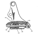
図3は、枢支部204によって連結される一対のアーム202、203を有するチェーンテンショニング装置を示している。スプリング206により付勢されるカムブロック205によって、アーム203がチェーン(図示なし)に緊張力を付与するように、アーム202、203は互いに離れるように付勢される。チェーンの負荷逆転の際にアーム203が破壊するのを防止するために、キャッチディスク209およびロッドが配置され、スプリング付勢のカムブロック205の戻りの動きを防止する。
【0016】
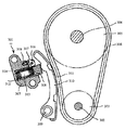
図4は、ラチェット装置を使用するテンショナの例を示している。ラチェットテンショナ301は、プランジャ308を受け入れるための穴312を有するテンショナハウジング307と、軸316によってテンショナハウジング307に枢支されかつラチェットスプリング318によって付勢されるラチェット爪317とを備えている。プランジャ308は、その一方の外側に、ラチェット爪317と係合する歯を有している。プランジャ308は、テンショナレバー310と接触するように、中空部分313内部の流体とプランジャスプリング314とによって穴312から押し出されるように付勢される。テンショナレバー310は、支持軸309上に枢支され、シュー面311を有している。シュー面311は、カムシャフト304およびそのスプロケット305と、クランクシャフト302およびそのスプロケット303との回りに巻き付けられるタイミングチェーン306の弛み側に接触して張力を与える。プランジャ308の穴312に対する出入りの動きは、その歯と、その歯に係合するラチェット爪317とによって制限される。
【0017】
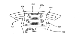
図5は、米国特許第6,599,209号明細書のテンショニング装置を示している。このテンショニング装置421は、テンショナトラック423に連結された開放ハニカム形状の相互連結部424を有する一体型の支持体422を有している。テンショナトラック423は、コイルスプリング25によって弾性的に支持されている。テンショナ421を据え付けるのに、取付孔420が用いられている。先行技術の図6aおよび6bに示す他の実施態様においては、一対のテンショナトラック406が、リブ状の相互連結部407によって連結されて一体に形成されている。相互連結部407は、弾性変形可能であり、折曲部408を有する。テンショナトラック406と支持体(図示せず)との間には、単一の板バネ409または板バネの集合体409aのいずれかが配置される。この米国特許第6,599,209号明細書のテンショニング装置の欠点の1つは、スプリングがテンショナの全面に沿ってではなくテンショナトラックの中心のみにしか緊張力を付与しないという点である。もう1つの欠点は、テンショナが一体品であるために、この組立品においてはスプリングを支持体内部に配置する必要があるという点である。
【発明の開示】
【発明が解決しようとする課題】
【0018】
本発明は、追従性ブレードスプリングを備えた新規な構成の機械式チェーンテンショナを提供しようとしている。
【課題を解決するための手段】
【0019】
本体と、弾性チェーンガイド要素と、少なくとも1つのブレードスプリングと、少なくとも1つのブラケットとを有し、チェーンに張力を付与するためのテンショナである。テンショナの本体は、湾曲形状を有する表面と、表面の長さに沿って長手方向に設けられる溝とを備えている。本体表面上の弾性チェーンガイド要素は、チェーン接触面と、本体の端部の回りに巻き付けられる2つの端部とを有する。チェーンガイド要素は、チェーン接触面が本体から離れて押し出されるように付勢されている。ブレードスプリングは、その端部が溝の拘束手段の中に嵌め込まれる形で溝の中に存在し、チェーンガイドを本体から外向きにかつ本体から離すように押し出す。本体の端部と弾性のチェーンガイドの端部との間には隙間が存在する。
【0020】
別の実施態様においては、チェーンの弛み側スパンおよび張り側スパンに第1および第2のテンショナが存在している。第1のテンショナにおけるブレードスプリングのバネ力は、第2のテンショナのブレードスプリングのバネ力よりも大きくし、または小さくし、あるいはそれに等しくする。
【0021】
さらに別の実施態様においては、第1のテンショナの本体端部と弾性チェーンガイドの端部との間の隙間が、第2のテンショナの本体端部と弾性チェーンガイドの端部との間の隙間よりも大きくなっている。
【発明を実施するための最良の形態】
【0022】
以下、本発明の実施例を添付図面に基づいて説明する。
【0023】
図7〜9は、本発明の第1の実施態様のテンショナを、駆動スプロケットおよび被駆動スプロケット(図示なし)の回りに巻かれる新品のチェーン500とともに示している。テンショナ601は弛み側スパンの外側に配置される。
【0024】
図9および図12を参照すると、ブラケット本体514が、新品のチェーンの走行経路に類似した湾曲形状の面514cを有し、新品のチェーンはチェーンガイド要素512によって制御される。側部515aと、底部515bと、溝515の両端部における凹部ポケット部515cとを備えたカット溝515が、表面514cの長さに沿って長手方向に設けられる。少なくとも1つのブレードスプリング518(図14参照)が、幾分平坦状にされてカット溝515の中に装着される。ブレードスプリング518は、その自由状態においては、長さ方向に湾曲した矩形状部材であり、その組付け状態においては、ブラケット本体514とチェーンガイド要素512との間のカット溝515の中にほとんど湾曲しない状態で嵌め込まれている。溝515の両端部における凹部ポケット部515cは、拘束手段であるとともに、ブレードスプリング518がその自由状態に湾曲しようとする際のブレードスプリング端に対する支持面として機能する。ブレードスプリング518は、ブレードスプリング518がその自由状態に湾曲しようとする際に、チェーンガイド要素512の下面512eに離反力を作用させ、それによって、チェーンガイド要素512を、ブラケット本体514から外向きにかつその本体514から離すようにチェーン500に向かって押し出し、チェーンガイド要素512をチェーン部分と常時接触させる。ブラケット本体514の表面514cは、過大なチェーン力に対抗するチェーンガイド要素512のストッパとして作用する。ブラケット本体514の表面514cの両側にはガイド516aおよび516bが存在し、例えば摩耗したチェーンの場合のようにチェーンガイド要素512が延びた状態において、チェーンガイド要素512を「Z」方向に保持することを補助する。ブラケットガイド516aおよび516bは、ブラケット本体514に固定取り付けするか、あるいはその代わりにブラケット本体514に一体化するのが好ましい。ブラケット本体514の孔513は、ブラケット本体514をエンジンブロックまたは他の表面に強固に固定するためのボルト(図示せず)を受け入れるためのものである。
【0025】
チェーンガイド要素512は、図13に示すように、チェーン摺動面512bとして作用する中央部分によって互いに連結される第1の端部512cおよび第2の端部512dを有している。チェーン摺動面512bは、チェーン500と摺動接触する。チェーンガイド要素512のチェーン摺動面512bに沿ってその両側にガイド512aが設けられ、チェーン500を摺動面512bに沿ってガイドする。チェーンガイド要素512の第1の端部512cおよび第2の端部512dは、下向きにかつ摺動面の中心に向かうように湾曲成形される。チェーンガイド要素512はブラケット本体514よりも大きく、チェーンガイド要素512の湾曲した第1の端部512cおよび第2の端部512dは、ブラケット本体514のそれぞれの第1の端部514aおよび第2の端部514bを受け入れ、チェーンガイド要素512をブラケット本体514に弛やかに固定する。チェーンガイド要素512がチェーン500およびブレードスプリング518に沿うように、チェーンガイド要素512は、所定の温度において半可撓性である材料から作製されるのが好ましい。チェーンガイド要素512の第1および第2の端部512c、512dと、ブラケット本体514の第1および第2の端部514a、514bとの間には、隙間Cが存在している。ブレードスプリング518が、チェーンガイド要素512をブラケット本体514から離すように外向きに押し出すにつれて、チェーンガイド要素512がこれ以上曲げられなくなるまで、ブラケット本体514の端部514a、514bとチェーンガイド要素512の端部512c、512dとの間の隙間Cが小さくなる。
【0026】
図7および図8に示すように、テンショナ601は新品のチェーンの弛み側スパンに配置されている。弛み側スパンはブラケットガイド516a、516bの間に受け入れられ、チェーンガイド要素512のチェーン摺動面512b上を摺動する。テンショナ601のチェーンガイド要素512は所定の温度において半可撓性であるので、ブレードスプリング518が、チェーンガイド要素512をブラケット本体から離すように押し出し、チェーンスパンに張力を付与するとともに、チェーンスパンと常時接触してチェーンスパンと一致する。
【0027】
図9は、チェーンの弛み側スパンに配置される追従型テンショニング装置601の断面図であり、新品のチェーンとともに、チェーンガイド要素512およびブレードスプリング518の配置を示している。図14は、ブラケット本体514のカット溝515内に装着された状態よりもさらに湾曲した自由状態におけるブレードスプリング518を示している。
【0028】
図10は、摩耗したチェーン500aの弛み側スパンに配置されたブレードスプリング518aを有するテンショナ601を示している。図11は、ブレードスプリング518aを含むテンショナの断面図である。摩耗したチェーンの場合のブレードスプリング518aは、新品のチェーンの場合のブレードスプリング518よりも大きく湾曲しあるいは曲げられている。チェーンが摩耗して延びるにつれて、ブレードスプリングは、より大きく曲がり、チェーンガイド要素512を摩耗チェーンに押し付けて接触させる。カット溝515の底部515bとブレードスプリング518aとの間には隙間519が存在する。
【0029】
ブレードスプリング518をその平坦状態から湾曲させようとする強いスプリング力と、チェーンガイド要素512およびブラケット本体514の端部間の弛みまたは隙間とを有することによって、テンショナ601のチェーンガイド要素512は、チェーンが摩耗しているか新品であるかに関係なく、チェーン500と常時接触して、システムの設計寿命のためのチェーン制御を確実なものにする。
【0030】
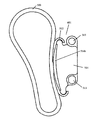
図15は、本発明の第2の実施態様を示している。この実施態様においては、第1のテンショナ601がチェーン500の弛み側スパンに配置され、第2のテンショナ701が張り側スパンに配置される。第1および第2のテンショナは、全く同一であり、第1の実施態様において述べたのと同じ対応要素を有する。その記述を以下に繰り返す。
【0031】
ブラケット本体514は、新品のチェーンの走行経路に類似した緩く湾曲する形状の面514cを有し、新品のチェーンはチェーンガイド要素512によって制御される。側部515aと、底部515bと、溝515の両端部における凹部ポケット部515cとを備えたカット溝515が、面514cの長さに沿って長手方向に設けられる。少なくとも1つのブレードスプリング518(図14参照)が、幾分平坦状にされてカット溝515の中に装着される。ブレードスプリング518は、その自由状態においては、長さ方向に湾曲した矩形状部材であり、その組付け状態においては、ブラケット本体514およびチェーンガイド要素512間のカット溝515の中にほとんど湾曲しない状態で嵌め込まれている。溝515の両端部における凹部ポケット部515cは、拘束手段であるとともに、ブレードスプリング518がその自由状態に湾曲しようとする際のブレードスプリング端に対する支持面として機能する。ブレードスプリング518は、ブレードスプリング518がその自由状態に湾曲しようとする際に、チェーンガイド要素512の下面512eに離反力を作用させ、それによって、チェーンガイド要素512をブラケット本体514からから離すようにブラケット本体514に外向きにチェーン500に向かって押し出し、チェーンガイド要素512をチェーンスパン部分と常時接触させる。ブラケット本体514の514cは、過大なチェーン力に対抗するチェーンガイド要素512のストッパとして作用する。ブラケット本体514の面514cの両側にはガイド516a、516bが存在し、例えば摩耗したチェーンとともに用いられる場合のように、チェーンガイド要素512が延びた状態において、チェーンガイド要素512上のチェーンスパン部分を「Z」方向に保持するのを補助する。ブラケットガイド516a、516bは、ブラケット本体514に固定し、あるいはその代わりにブラケット本体514に一体化するのが望ましい。ブラケット本体514の孔513は、ブラケット本体514をエンジンブロックまたは他の表面に強固に固定するためのボルト(図示なし)を受け入れるためのものである。
【0032】
チェーンガイド要素512は、図13に示しているように、チェーン摺動面512bとして作用する中央部分によって互いに連結される第1の端部512cおよび第2の端部512dを有している。チェーン摺動面512bは、チェーン500と摺動接触する。チェーンガイド要素512のチェーン摺動面512bに沿って摺動面の両側にガイド512aが設けられ、チェーン500を摺動面512bに沿ってガイドする。チェーンガイド要素512の第1の端部512cおよび第2の端部512dは、下向きにかつ摺動面の中心に向かうように湾曲成形されている。チェーンガイド要素512はブラケット本体514よりも大きく、チェーンガイド要素512の湾曲した第1の端部512cおよび第2の端部512dは、ブラケット本体514のそれぞれの第1の端部514aおよび第2の端部514bを受け入れ、チェーンガイド要素512をブラケット本体514に弛やかに固定している。チェーンガイド要素512がチェーン500およびブレードスプリング518に沿うように、チェーンガイド要素512は、所定の温度において半可撓性である材料から作製されていることが望ましい。チェーンガイド要素512の第1および第2端部512c、512dと、ブラケット本体514の第1および第2端部514a、514bとの間には、隙間(クリアランス)Cが存在している。ブレードスプリング518が、チェーンガイド要素512をブラケット本体514から離すように外向きに押し出すにつれて、チェーンガイド要素512がそれ以上曲げられなくなるまで、ブラケット本体514の端部514a、514bとチェーンガイド要素512の端部512c、512dとの間の隙間Cは小さくなる。
【0033】
あるいは、第2の実施態様のように、2つのテンショナ601、701が設けられる場合には、ブレードスプリングのバネ力を異ならせるようにしてもよい。一例として、一方の側(弛み側)においてのみチェーンの弛みを取り去るためには、張り側スパンのチェーンガイド要素512は、通常、ブラケット本体514のストッパ514cに当接している。捩じりや内燃機関の停止時に生じる逆回転による負荷の逆転が生じた場合には、弛み側スパンおよび張り側スパンが逆転して、通常のチェーン回転が再開されたときに歯飛びにつながることになる従動スプロケットへのチェーンの過剰な巻き付きを防止して張り側スパンの弛みを取り去ることによって、張り側スパンのテンショナが反応するだろう。張り側スパンのスプリングが弱いと、チェーンが通常の張り側経路を回復して、チェーンガイド要素512がブラケット本体514に再度当接するときの衝撃を和らげることにもなる。
【0034】
別の例においては、チェーンの双方のスパンの弛みを均等に除去するために、張り側スパンのブレードスプリング518のバネ力を僅かに高くしまたは等しくするが、双方の側のバネ力は、従動スプロケットの逆転の力に打ち勝ちかつ双方のスパンにストッパ514cから離れる緊張力を作用させるように増大させられている。
【0035】
したがって、以上説明した本発明の実施態様は、本発明の原理の適用を単に例示するものに過ぎないことが理解されるべきである。本明細書に例示された実施態様に詳細に言及することは、特許請求の範囲を限定するようには意図されていない。特許請求の範囲そのものが、本発明の本質とみなされる特徴を説明している。
【図面の簡単な説明】
【0036】
【図1】 先行技術の液圧テンショナを示している。
【図2】 先行技術のブレードテンショナを示している。
【図3】 別の先行技術のテンショナを示している。
【図4】 先行技術のラチェット式テンショナを示している。
【図5】 一体型の先行技術のテンショナを示している。
【図6a】 一体型の先行技術のテンショナの他の実施態様を示している。
【図6b】 一体型の先行技術のテンショナの別の実施態様を示している。
【図7】 本発明の第1の実施態様によるチェーンテンショナの斜視図である。
【図8】 前記テンショナの正面図である。
【図9】 新品のチェーン状態における図8のテンショナの断面図である。
【図10】 チェーン摩耗状態における図8のテンショナの正面図である。
【図11】 図10のテンショナの断面図である。
【図12】 固定ブラケット本体の斜視図である。
【図13】 弾性チェーンガイド要素の斜視図である。
【図14】 本発明のテンショナのスプリングの自由状態における斜視図である。
【図15】 本発明の第2の実施態様の正面図である。
【符号の説明】
【0037】
500: チェーン
512: チェーンガイド要素
514: ブラケット本体
518: ブレードスプリング[0001]
This application relates to a co-filed application (title “PIVOTING MECHANICAL BLADE TENSIONER WITH COMPLIANT BLADE SPRING”), the contents of which are hereby incorporated by reference. The present application also includes US patent application Ser. No. 10 / 984,450 filed Nov. 9, 2004 (title “COMPLIANT SNUBBER”) and US Patent Application No. 10 / 692,182 filed Sep. 11, 2004. The content of this application is also incorporated herein by reference with respect to the specification (titled “Complaint Chain Guide With Blade Spring”).
【Technical field】
[0002]
The present invention relates to the field of tensioners, and more particularly to a mechanical tensioner with a compliant blade spring.
[Background]
[0003]
A tensioning device such as a hydraulic tensioner is used as a control device for a power transmission chain or similar power transmission device when the chain travels between a plurality of sprockets. In this apparatus, since the chain transmits power from the drive shaft to the driven shaft, a part of the chain is relaxed and the other part is tensioned. In general, in the case of a toothed chain, it is important to apply a certain amount of tension to the chain to maintain it in order to prevent noise, slip or tooth meshing. Such slip prevention is particularly important in the case of a chain drive camshaft of an internal combustion engine. The reason is that if tooth skip occurs, the timing of the camshaft changes, which may cause damage or engine malfunction.
[0004]
However, in the harsh environment of an internal combustion engine, various factors can cause chain tension fluctuations. For example, wide changes in temperature and differences in thermal expansion coefficients in various parts of the engine can cause chain tension to change between abnormally high or low values. During long-term use, wear of power transmission system components can reduce chain tension. Furthermore, torsional vibrations induced by the camshaft and crankshaft cause large fluctuations in chain tension. An engine reversal that occurs, for example, when the engine is stopped or when it fails to start can also cause chain tension variations. For these reasons, a mechanism for removing excessive tension on the tension side of the chain and securing necessary tension on the relaxation side of the chain is required.
[0005]
Hydraulic tensioners are a common way to maintain proper chain tension. Generally, this mechanism uses a lever arm that is pressed against the chain on the relaxed side of the power transmission system. The lever arm must press the chain and tension the chain when the chain relaxes, and it must be very strong when the chain is tensioned.
[0006]
To achieve this, as shown in FIG. 1 of the prior art, the
[0007]
Typically, valves are used for regulating the flow of fluid to and from the pressure chamber. For example, the inflow check valve 6 usually includes a ball check valve, and when the pressure in the chamber decreases as a result of the outward movement of the piston 2, the ball check valve is caused to flow the fluid into the pressure chamber 4. Opens. When the pressure in the pressure chamber is high, the inflow check valve closes to prevent fluid from exiting the pressure chamber. By closing the inflow check valve 6, the piston chamber is prevented from contracting, and therefore the piston is prevented from contracting, and a so-called “return” function is realized.
[0008]
Many tensioners also employ a pressure relief mechanism that causes fluid to flow out of the pressure chamber when the pressure in the chamber is high, thereby allowing piston degeneration in response to a sudden increase in chain tension. In some tensioners, the pressure relief mechanism is a spring-loaded check valve. This check valve opens when the pressure exceeds a certain pressure point. Some tensioners use valves that perform both an inflow check function and a pressure relief function.
[0009]
Other mechanisms employ a restricted flow path that allows fluid to flow out of the fluid chamber so that the volume of flow out of the fluid chamber is minimal unless the pressure in the fluid chamber increases. Yes. The restricted flow path is provided, for example, via a gap between the piston and the housing hole, a vent tube at the protruding end of the piston, or a vent member between the fluid chamber and the fluid reservoir.
[0010]
A hydraulic tensioner for use with a tensioner arm or shoe is shown in US Pat. No. 5,967,921, the contents of which are hereby incorporated by reference. The hydraulic chain tensioner typically has a plunger that is slidably incorporated into the chamber and is biased outward by a spring to tension the chain. In many cases, a lever, an arm or a shoe is used at the end of the plunger to assist in tensioning the chain. The hydraulic pressure from an external pressure source such as an oil pump flows into the chamber through a flow path formed in the housing. The plunger moves outward toward the arm by the combined force of the hydraulic pressure and the spring force.
[0011]
For the case where the plunger moves in the opposite direction (inward) away from the chain, a check valve is generally provided to restrict fluid flow from the chamber. In such a system, the tensioner implements a so-called check function. That is, the operation of the plunger is easy in one direction (outward), but difficult in the reverse direction.
[0012]
A blade tensioner is a tensioner commonly used to control chains or belts where load fluctuations are not severe enough to displace the springs excessively. A ratchet with backlash has been added to the tensioner to limit substantial backward or tensionless movement in the tensioning device.
[0013]
Prior art FIG. 2 shows an example of a blade tensioner. The
[0014]
The
[0015]
FIG. 3 shows a chain tensioning device having a pair of
[0016]
FIG. 4 shows an example of a tensioner that uses a ratchet device. The
[0017]
FIG. 5 shows the tensioning device of US Pat. No. 6,599,209. The
DISCLOSURE OF THE INVENTION
[Problems to be solved by the invention]
[0018]
The present invention seeks to provide a novel configuration of mechanical chain tensioner with a compliant blade spring.
[Means for Solving the Problems]
[0019]
Main body and bullet Sex A tensioner having a chain guide element, at least one blade spring, and at least one bracket for tensioning the chain. The body of the tensioner Curved A surface having a shape and a groove provided in the longitudinal direction along the length of the surface are provided. Bullets on the surface of the main body Sex The chain guide element has a chain contact surface and two ends that are wrapped around the end of the body. Chain guide element Is The Chain contact surface But Push away from the body Is energized to be . The blade spring is present in the groove with its end fitted into the groove restraining means and pushes the chain guide outward and away from the body. There is a gap between the end of the main body and the end of the elastic chain guide.
[0020]
In another embodiment, first and second tensioners are present on the slack side and tight side spans of the chain. The spring force of the blade spring in the first tensioner is greater than, less than, or equal to the spring force of the blade spring of the second tensioner.
[0021]
In yet another embodiment, the gap between the body end of the first tensioner and the end of the elastic chain guide is a gap between the body end of the second tensioner and the end of the elastic chain guide. Is bigger than.
BEST MODE FOR CARRYING OUT THE INVENTION
[0022]
Embodiments of the present invention will be described below with reference to the accompanying drawings.
[0023]
FIGS. 7-9 show the tensioner of the first embodiment of the present invention with a
[0024]
Referring to FIGS. 9 and 12, the
[0025]
As shown in FIG. 13, the
[0026]
As shown in FIGS. 7 and 8, the
[0027]
FIG. 9 is a cross-sectional view of the follow-up
[0028]
FIG. 10 shows a
[0029]
By having a strong spring force that tends to curve the
[0030]
FIG. 15 shows a second embodiment of the present invention. In this embodiment, the
[0031]
The
[0032]
As shown in FIG. 13, the
[0033]
Alternatively, when two
[0034]
In another example, the tension force of the
[0035]
Accordingly, it is to be understood that the above-described embodiments of the present invention are merely illustrative of the application of the principles of the present invention. Reference in detail to the embodiments illustrated herein is not intended to limit the scope of the claims. The claims themselves describe the features that are considered essential to the invention.
[Brief description of the drawings]
[0036]
FIG. 1 illustrates a prior art hydraulic tensioner.
FIG. 2 shows a prior art blade tensioner.
FIG. 3 illustrates another prior art tensioner.
FIG. 4 illustrates a prior art ratchet tensioner.
FIG. 5 illustrates an integrated prior art tensioner.
FIG. 6a shows another embodiment of an integrated prior art tensioner.
FIG. 6b shows another embodiment of an integrated prior art tensioner.
FIG. 7 is a perspective view of a chain tensioner according to a first embodiment of the present invention.
FIG. 8 is a front view of the tensioner.
9 is a cross-sectional view of the tensioner of FIG. 8 in a new chain state.
FIG. 10 is a front view of the tensioner of FIG. 8 in a chain wear state.
11 is a cross-sectional view of the tensioner of FIG.
FIG. 12 is a perspective view of a fixed bracket body.
FIG. 13 is a perspective view of an elastic chain guide element.
FIG. 14 is a perspective view of a tensioner spring of the present invention in a free state.
FIG. 15 is a front view of a second embodiment of the present invention.
[Explanation of symbols]
[0037]
500: Chain
512: Chain guide element
514: Bracket body
518: Blade spring
Claims (8)
湾曲形状を有する面と、前記面の長さに沿って長手方向に設けられかつその各端部に拘束手段を有する溝とを有する本体と、
前記本体の前記面の上に設けられ、前記本体の端部の回りに巻き付けられる2つの端部およびチェーン接触面を有する弾性チェーンガイド要素と、
前記本体の前記溝の中に設けられかつ端部が前記拘束手段で拘束され、前記弾性チェーンガイド要素を前記本体から離れる外向きに押し出すように付勢する少なくとも1つのブレードスプリングと、
を備えたテンショナ。A tensioner that applies tension to the chain,
A body having a curved surface, and a groove provided in a longitudinal direction along the length of the surface and having a restraining means at each end thereof;
A resilient chain guide element, wherein provided on the surface of the body, to have a two ends wrapped around the ends and chain contact surface of said body,
Wherein and end provided in the groove of the body is restrained by the restraining means, at least one blade spring biasing the resilient chain guide element to push outward away from the body,
Tensioner with
前記チェーンの弛み側スパンに配置された第1テンショナと、
前記チェーンの張り側スパンに配置された第2テンショナとを備え、
前記第1のテンショナが、
湾曲形状を有する面と、前記面の長さに沿って長手方向に設けられかつその各端部に拘束手段を有する溝とを備えた本体と、
前記本体の前記面の上に設けられ、前記本体の端部の回りに巻き付けられる2つの端部およびチェーン接触面を有する弾性チェーンガイド要素と、
前記本体の前記溝の中に設けられかつ端部が前記拘束手段で拘束され、前記弾性チェーンガイド要素を前記本体から離れる外向きに押し出すように付勢する少なくとも1つのブレードスプリングとを備え、
前記第2のテンショナが、
湾曲形状を有する面と、前記面の長さに沿って長手方向に設けられかつその各端部に拘束手段を有する溝とを備えた本体と、
前記本体の前記面の上に設けられ、前記本体の端部の回りに巻き付けられる2つの端部およびチェーン接触面を有する弾性チェーンガイド要素と、
前記本体の前記溝の中に設けられかつ端部が前記拘束手段で拘束され、前記弾性チェーンガイド要素を前記本体から離れる外向きに押し出すように付勢する少なくとも1つのブレードスプリングとを備えている、
ことを特徴とするテンショニングシステム。A tensioning system having a slack side span and a tension side span to impart tension to the chain,
A first tensioner disposed on the slack side span of the chain;
A second tensioner disposed on the tension side span of the chain,
The first tensioner is
A main body comprising a surface having a curved shape, and a groove provided in a longitudinal direction along the length of the surface and having a restraining means at each end thereof;
A resilient chain guide element, wherein provided on the surface of the body, to have a two ends wrapped around the ends and chain contact surface of said body,
At least one blade spring provided in the groove of the main body and having an end portion restrained by the restraining means and biasing the elastic chain guide element to be pushed outward away from the main body;
The second tensioner is
A main body comprising a surface having a curved shape, and a groove provided in a longitudinal direction along the length of the surface and having a restraining means at each end thereof;
A resilient chain guide element, wherein provided on the surface of the body, to have a two ends wrapped around the ends and chain contact surface of said body,
And at least one blade spring provided in the groove of the body and having an end portion restrained by the restraining means and biasing the elastic chain guide element to be pushed outward away from the body. ,
A tensioning system characterized by that.
Applications Claiming Priority (3)
| Application Number | Priority Date | Filing Date | Title |
|---|---|---|---|
| US11/168,769 US7641577B2 (en) | 2005-06-28 | 2005-06-28 | Mechanical chain tensioner with compliant blade spring |
| US11/168,769 | 2005-06-28 | ||
| PCT/US2006/019378 WO2007001674A1 (en) | 2005-06-28 | 2006-05-19 | Mechanical chain tensioner with compliant blade spring |
Publications (2)
| Publication Number | Publication Date |
|---|---|
| JP2008544195A JP2008544195A (en) | 2008-12-04 |
| JP5000646B2 true JP5000646B2 (en) | 2012-08-15 |
Family
ID=36952554
Family Applications (1)
| Application Number | Title | Priority Date | Filing Date |
|---|---|---|---|
| JP2008519302A Expired - Fee Related JP5000646B2 (en) | 2005-06-28 | 2006-05-19 | Mechanical chain tensioner with followable blade spring |
Country Status (6)
| Country | Link |
|---|---|
| US (1) | US7641577B2 (en) |
| JP (1) | JP5000646B2 (en) |
| KR (1) | KR101232104B1 (en) |
| CN (1) | CN101208540B (en) |
| DE (1) | DE112006001473T5 (en) |
| WO (1) | WO2007001674A1 (en) |
Families Citing this family (22)
| Publication number | Priority date | Publication date | Assignee | Title |
|---|---|---|---|---|
| JP2006200577A (en) * | 2005-01-18 | 2006-08-03 | Tsubakimoto Chain Co | Guide for transmission device |
| WO2007095420A1 (en) * | 2006-02-17 | 2007-08-23 | Borgwarner Inc | Force limiting tensioning arm |
| CN101495775B (en) * | 2006-08-11 | 2011-09-07 | 博格华纳公司 | Assembly system and method for a tensioned chain drive system |
| WO2008038359A1 (en) * | 2006-09-28 | 2008-04-03 | Daido Kogyo Co., Ltd. | Chain tensioner |
| US8876642B2 (en) * | 2009-03-23 | 2014-11-04 | Borgwarner Inc. | U-shaped chain guide bracket |
| CN103154571B (en) * | 2010-08-09 | 2016-03-23 | 克劳伊斯传动装置产品有限公司 | There is the blade tensioner of spring retention performance |
| JP5813115B2 (en) * | 2010-08-30 | 2015-11-17 | クロイズ ギア アンド プロダクツインコーポレイテッド | Blade tensioner and bracket for blade tensioners including pocket pivot mechanism |
| DE102010051951A1 (en) | 2010-11-19 | 2012-05-24 | Schaeffler Technologies Gmbh & Co. Kg | tensioning device |
| JP5681562B2 (en) * | 2011-05-19 | 2015-03-11 | 本田技研工業株式会社 | Chain tensioner device |
| DE102012014943A1 (en) * | 2012-07-27 | 2014-01-30 | Iwis Motorsysteme Gmbh & Co. Kg | Clamp or guide rail with extruded Gleitbelagkörper |
| US9206886B2 (en) | 2012-12-09 | 2015-12-08 | Cloyes Gear And Products, Inc. | Chain tensioner |
| JP2015137685A (en) * | 2014-01-21 | 2015-07-30 | 株式会社椿本チエイン | guide shoe |
| DE102015008877A1 (en) * | 2015-07-08 | 2016-08-04 | Iwis Motorsysteme Gmbh & Co. Kg | Modular sliding or tensioning rail |
| JP6420629B2 (en) * | 2014-10-30 | 2018-11-07 | ボーグワーナー インコーポレーテッド | Chain guide and chain tensioner arm |
| DE102015102402A1 (en) * | 2015-02-20 | 2016-08-25 | Jungheinrich Aktiengesellschaft | Hubanordnung a lift truck and pallet truck |
| WO2016144959A1 (en) * | 2015-03-09 | 2016-09-15 | Cloyes Gear And Products, Inc. | Chain tensioner plastic blade with improved structural rigidity at the spring-end reaction surfaces of the blade |
| CN106051075B (en) * | 2016-07-14 | 2020-02-14 | 广东格兰仕微波炉电器制造有限公司 | Damping structure with transmission |
| KR101923657B1 (en) * | 2017-01-12 | 2018-11-30 | 유신정밀공업 주식회사 | Chain Tensioner |
| CN109654183A (en) | 2017-10-12 | 2019-04-19 | 博格华纳公司 | Hydraulic tensioner with adjustable check-valves |
| CN109667898A (en) * | 2017-10-17 | 2019-04-23 | 舍弗勒技术股份两合公司 | Hydranlic tensioner |
| US11796040B2 (en) | 2021-01-22 | 2023-10-24 | Borgwarner Inc. | Method(s) to apply tension to increase drivetrain jump torque capacity |
| US11815180B2 (en) * | 2021-08-24 | 2023-11-14 | Schaeffler Technologies AG & Co. KG | Tensioner with stamped pivot pin |
Family Cites Families (46)
| Publication number | Priority date | Publication date | Assignee | Title |
|---|---|---|---|---|
| US866702A (en) * | 1907-02-21 | 1907-09-24 | William H Weeks | Machine for coating confectionery. |
| US1777527A (en) * | 1926-12-29 | 1930-10-07 | Morse Chain Co | Chain-adjusting device |
| US1988421A (en) * | 1933-09-19 | 1935-01-15 | Baldwin Duckworth Chain Corp | Driving mechanism |
| US2191946A (en) * | 1936-11-30 | 1940-02-27 | Weller John | Tensioning device for transmission chains and the like |
| GB505746A (en) | 1937-10-11 | 1939-05-11 | John Weller | Improvements in tensioning devices for transmission chains and the like |
| US2210276A (en) * | 1938-07-12 | 1940-08-06 | Morse Chain Co | Chain adjuster |
| US2261316A (en) * | 1939-02-17 | 1941-11-04 | Weller John | Tensioning device for transmission chains |
| JPS5719874Y2 (en) * | 1977-06-09 | 1982-04-27 | ||
| US4193314A (en) * | 1978-03-22 | 1980-03-18 | General Motors Corporation | Timing chain snubber |
| US4395251A (en) * | 1980-02-11 | 1983-07-26 | Borg-Warner Limited | Tensioning devices |
| FR2496815B1 (en) | 1980-12-19 | 1985-06-21 | Sedis Transmissions Meca | MECHANICAL TENSION DEVICE FOR A CHAIN OR TRANSMISSION BELT |
| JPS57134055A (en) | 1981-02-10 | 1982-08-19 | Honda Motor Co Ltd | Tensioner device for endless belt |
| JPS60116449U (en) * | 1984-01-18 | 1985-08-06 | エヌオーケー株式会社 | chain tensioner |
| JPS61147928A (en) | 1984-12-21 | 1986-07-05 | Nissan Motor Co Ltd | Edge bending apparatus |
| JPH07117129B2 (en) * | 1986-06-24 | 1995-12-18 | ヤマハ発動機株式会社 | Chain guide for overhead camshaft engine |
| US5180340A (en) * | 1991-10-31 | 1993-01-19 | General Motors Corporation | Guide mechanism for a traveling chain transmission |
| US5286234A (en) * | 1992-07-27 | 1994-02-15 | Cloyes-Iwis Company L.P. | Chain tensioner apparatus |
| DE4224753A1 (en) * | 1992-07-27 | 1994-02-03 | Ebert Siegfried Dipl Ing Oec | Automatic tensioning and damping element for endless chain drives |
| US5266066A (en) * | 1992-08-21 | 1993-11-30 | Borg-Warner Automative, Inc. | Spring blade chain tensioner |
| JP2563958Y2 (en) * | 1993-08-30 | 1998-03-04 | 本田技研工業株式会社 | Chain guide device |
| JPH0981071A (en) | 1995-09-18 | 1997-03-28 | Hitachi Ltd | Plasma display panel |
| DE19536643A1 (en) * | 1995-09-30 | 1997-04-03 | Schaeffler Waelzlager Kg | Clamping device for a control drive |
| US5797818A (en) * | 1996-04-02 | 1998-08-25 | Cloyes Gear And Products, Inc. | Chain tensioner with damping feature |
| US5853341A (en) * | 1997-03-26 | 1998-12-29 | Borg-Warner Automotive, Inc. | Laminated chain tensioner arms or guides |
| EP0892193A1 (en) * | 1997-07-14 | 1999-01-20 | Morse Tec Europe S.p.A. | A device for take-up of tolerance in a chain drive |
| US5967921A (en) * | 1997-10-09 | 1999-10-19 | Borg-Warner Automotive, Inc. | Hydraulic chain tensioner with molded plastic body |
| JP3113224B2 (en) * | 1997-10-14 | 2000-11-27 | 株式会社椿本チエイン | Tensioner guide |
| US6155941A (en) * | 1998-12-15 | 2000-12-05 | Borgwarner Inc. | Hydraulic tensioner having a flexible blade arm |
| DE60041179D1 (en) * | 1999-02-10 | 2009-02-05 | Cloyes Gear & Products Inc | CHAIN TENSIONER IN A CLOSED SPACE |
| JP2000230611A (en) * | 1999-02-15 | 2000-08-22 | Borg Warner Automotive Kk | Blade tensioner |
| JP3286259B2 (en) * | 1999-03-03 | 2002-05-27 | 株式会社椿本チエイン | Chain guide |
| DE19923923B4 (en) * | 1999-05-26 | 2005-08-04 | Ina-Schaeffler Kg | Clamping device for tensioning a traction device |
| US6612952B1 (en) * | 1999-10-28 | 2003-09-02 | Borgwarner Inc. | Blade tensioner having spring blade cantilevered from distal end of arm |
| JP3432197B2 (en) * | 2000-02-02 | 2003-08-04 | 株式会社椿本チエイン | Ratchet type tensioner with backlash |
| US6322469B1 (en) * | 2000-04-21 | 2001-11-27 | Borgwarner Inc. | Dual arm chain tensioner for contacting multiple chain strands |
| US6554728B2 (en) * | 2000-10-05 | 2003-04-29 | Borgwarner, Inc. | Fastenerless chain snubber |
| JP2002120786A (en) | 2000-10-16 | 2002-04-23 | Honda Motor Co Ltd | Chain guide device for motorcycle |
| JP3998576B2 (en) * | 2000-10-17 | 2007-10-31 | クロイズ ギア アンド プロダクツ インコーポレイテッド | Blade type mechanical chain tensioner with external reinforcing ribs |
| AU2002219842A1 (en) * | 2000-11-17 | 2002-05-27 | Cloyes Gear And Products, Inc. | Snap-fit chain guide with locking connector arrangement |
| US6955621B2 (en) * | 2001-04-26 | 2005-10-18 | Borgwarner Inc. | Rotary actuating hydraulic tensioner |
| DE60214075T2 (en) * | 2001-05-17 | 2007-05-31 | Borgwarner Morse Tec Japan K.K., Nabari | Clamping device with leaf spring and chain arrangement |
| JP4065169B2 (en) * | 2002-09-11 | 2008-03-19 | 本田技研工業株式会社 | Chain tensioner device |
| US6849015B2 (en) * | 2003-01-31 | 2005-02-01 | Borgwarner Inc. | Ratcheting pivot arm tensioner with backlash |
| JP4311955B2 (en) | 2003-03-14 | 2009-08-12 | 大同工業株式会社 | Leaf spring type tensioner device |
| US6939259B2 (en) * | 2003-04-25 | 2005-09-06 | Borgwarner Inc. | Two-shot unified chain tensioner arm or guide |
| US7063635B2 (en) * | 2003-10-23 | 2006-06-20 | Borgwarner Inc. | Compliant chain guide with blade spring |
-
2005
- 2005-06-28 US US11/168,769 patent/US7641577B2/en active Active
-
2006
- 2006-05-19 KR KR1020087000108A patent/KR101232104B1/en active IP Right Grant
- 2006-05-19 CN CN2006800231936A patent/CN101208540B/en not_active Expired - Fee Related
- 2006-05-19 WO PCT/US2006/019378 patent/WO2007001674A1/en active Application Filing
- 2006-05-19 JP JP2008519302A patent/JP5000646B2/en not_active Expired - Fee Related
- 2006-05-19 DE DE112006001473T patent/DE112006001473T5/en not_active Withdrawn
Also Published As
| Publication number | Publication date |
|---|---|
| JP2008544195A (en) | 2008-12-04 |
| CN101208540A (en) | 2008-06-25 |
| CN101208540B (en) | 2012-06-13 |
| DE112006001473T5 (en) | 2008-05-15 |
| KR101232104B1 (en) | 2013-02-12 |
| KR20080018935A (en) | 2008-02-28 |
| US20060293136A1 (en) | 2006-12-28 |
| WO2007001674A1 (en) | 2007-01-04 |
| US7641577B2 (en) | 2010-01-05 |
Similar Documents
| Publication | Publication Date | Title |
|---|---|---|
| JP5000646B2 (en) | Mechanical chain tensioner with followable blade spring | |
| JP4968801B2 (en) | Long mechanical tensioner with compliant blade spring | |
| JP4912760B2 (en) | Tensioner | |
| US7628719B2 (en) | Mechanical strap tensioner for multi-strand tensioning | |
| US6358169B1 (en) | Chain tensioner system having a pivoting tensioner arm | |
| EP1984649B1 (en) | Force limiting tensioning arm | |
| US7455606B2 (en) | Mechanical chain tensioner with a rotational ratcheting device | |
| KR101330009B1 (en) | Ratchet mechanism for a chain drive | |
| US20110077114A1 (en) | Anchored mechanical strap tensioner for multi-strand tensioning | |
| JP7488463B2 (en) | Tensioner |
Legal Events
| Date | Code | Title | Description |
|---|---|---|---|
| A621 | Written request for application examination |
Free format text: JAPANESE INTERMEDIATE CODE: A621 Effective date: 20090428 |
|
| A977 | Report on retrieval |
Free format text: JAPANESE INTERMEDIATE CODE: A971007 Effective date: 20111031 |
|
| A131 | Notification of reasons for refusal |
Free format text: JAPANESE INTERMEDIATE CODE: A131 Effective date: 20111111 |
|
| A601 | Written request for extension of time |
Free format text: JAPANESE INTERMEDIATE CODE: A601 Effective date: 20120209 |
|
| A602 | Written permission of extension of time |
Free format text: JAPANESE INTERMEDIATE CODE: A602 Effective date: 20120216 |
|
| A601 | Written request for extension of time |
Free format text: JAPANESE INTERMEDIATE CODE: A601 Effective date: 20120309 |
|
| A602 | Written permission of extension of time |
Free format text: JAPANESE INTERMEDIATE CODE: A602 Effective date: 20120316 |
|
| A521 | Request for written amendment filed |
Free format text: JAPANESE INTERMEDIATE CODE: A523 Effective date: 20120330 |
|
| TRDD | Decision of grant or rejection written | ||
| A01 | Written decision to grant a patent or to grant a registration (utility model) |
Free format text: JAPANESE INTERMEDIATE CODE: A01 Effective date: 20120427 |
|
| A01 | Written decision to grant a patent or to grant a registration (utility model) |
Free format text: JAPANESE INTERMEDIATE CODE: A01 |
|
| A61 | First payment of annual fees (during grant procedure) |
Free format text: JAPANESE INTERMEDIATE CODE: A61 Effective date: 20120516 |
|
| R150 | Certificate of patent or registration of utility model |
Ref document number: 5000646 Country of ref document: JP Free format text: JAPANESE INTERMEDIATE CODE: R150 Free format text: JAPANESE INTERMEDIATE CODE: R150 |
|
| FPAY | Renewal fee payment (event date is renewal date of database) |
Free format text: PAYMENT UNTIL: 20150525 Year of fee payment: 3 |
|
| R250 | Receipt of annual fees |
Free format text: JAPANESE INTERMEDIATE CODE: R250 |
|
| R250 | Receipt of annual fees |
Free format text: JAPANESE INTERMEDIATE CODE: R250 |
|
| R250 | Receipt of annual fees |
Free format text: JAPANESE INTERMEDIATE CODE: R250 |
|
| R250 | Receipt of annual fees |
Free format text: JAPANESE INTERMEDIATE CODE: R250 |
|
| R250 | Receipt of annual fees |
Free format text: JAPANESE INTERMEDIATE CODE: R250 |
|
| R250 | Receipt of annual fees |
Free format text: JAPANESE INTERMEDIATE CODE: R250 |
|
| LAPS | Cancellation because of no payment of annual fees |