JP4857504B2 - Electric stapler staple detection mechanism - Google Patents
Electric stapler staple detection mechanism Download PDFInfo
- Publication number
- JP4857504B2 JP4857504B2 JP2001273328A JP2001273328A JP4857504B2 JP 4857504 B2 JP4857504 B2 JP 4857504B2 JP 2001273328 A JP2001273328 A JP 2001273328A JP 2001273328 A JP2001273328 A JP 2001273328A JP 4857504 B2 JP4857504 B2 JP 4857504B2
- Authority
- JP
- Japan
- Prior art keywords
- staple
- forming plate
- driver
- sensor
- sheet
- Prior art date
- Legal status (The legal status is an assumption and is not a legal conclusion. Google has not performed a legal analysis and makes no representation as to the accuracy of the status listed.)
- Expired - Lifetime
Links
Images


Classifications
-
- B—PERFORMING OPERATIONS; TRANSPORTING
- B27—WORKING OR PRESERVING WOOD OR SIMILAR MATERIAL; NAILING OR STAPLING MACHINES IN GENERAL
- B27F—DOVETAILED WORK; TENONS; SLOTTING MACHINES FOR WOOD OR SIMILAR MATERIAL; NAILING OR STAPLING MACHINES
- B27F7/00—Nailing or stapling; Nailed or stapled work
- B27F7/17—Stapling machines
- B27F7/38—Staple feeding devices
-
- B—PERFORMING OPERATIONS; TRANSPORTING
- B25—HAND TOOLS; PORTABLE POWER-DRIVEN TOOLS; MANIPULATORS
- B25C—HAND-HELD NAILING OR STAPLING TOOLS; MANUALLY OPERATED PORTABLE STAPLING TOOLS
- B25C5/00—Manually operated portable stapling tools; Hand-held power-operated stapling tools; Staple feeding devices therefor
- B25C5/16—Staple-feeding devices, e.g. with feeding means, supports for staples or accessories concerning feeding devices
Description
【0001】
【発明の属する技術分野】
この発明は、電動ステープラのステープル検出機構に関し、更に詳しくは、コピー紙などを綴じ合わせるために、シート状に形成されたステープルシートからステープルを分離してコの字型に成形する際に、成形機構の成形位置にステープルシートが位置しているかどうかを検知するステープル検出機構に関する。
【0002】
【従来の技術】
従来、コピー機械などのスタッカー等には電動ステープラが配置されているものがある。
【0003】
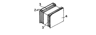
図16は、この電動ステープラ1の概略構成を示したものである。この電動ステープラ1では、真直状の軸片からなるステープル2を多数並列させ、接着剤によりシート状に接着したステープルシート3(図17参照)が用いられる。ステープルシート3は、図16に示すように、積層されてカートリッジ4内に格納される。ステープルシート3は、カートリッジ4からローラ5により一枚ずつステープル2の1本分若しくは2本分を送り出せるようになっている。
【0004】
送り方向の先端部に位置するステープル2は、両端部をコの字型に成形するフォーミングプレート6及び中間部を支持するアンビル7によって、1本ずつコの字型に成型された後、ドライバー8によってコピー紙の束9に差し込まれる。ドライバー8によって、コピー紙9を貫通した脚部はクリンチャー10によって折り曲げられて綴じ合わせが行われる。
【0005】
このカートリッジ4は、筒体形状を有する枠状のマガジン11に取り外し可能に収納されており、マガジン11は前記スタッカーのシャーシに、一例として固定され、クリンチャー10が上下動するようになっている。
【0006】
フォーミングプレート6とドライバー8はマガジン11のステープルシート3の送り方向先端部上方に配置され、駆動機構によって上下動自在とされており、フォーミングプレート6とドライバー8の駆動機構は、モーター及びカム機構を備えている。駆動機構は、コピー紙9が所定枚数クリンチャー10の上方の所定位置に送られると、フォーミングプレート6とドライバー8とを下降させ、クリンチャー10が上方に移動して、マガジン11との間にコピー紙9を挟み付け、ステープル2により綴じ合わせを行うようになっている。
【0007】
電動ステープラ1は、ステープルシート2の先端部がドライバの通路に送られているかどうかを検出するために、ステープルシート3の送り方向先端部のステープル3に接触して検出する接触式の図示しないステープルセンサを備えている。
【0008】
このステープルセンサは、フォーミングプレート6とドライバー8の駆動機構が設置されたドライバー8側であって、カートリッジ4と反対側の位置に配置され、てこ状の揺動運動をするものである。ステープルセンサは、一端をアンビル7側に延ばし、他端をカートリッジ4の反対側に延ばしており、ドライバー8側に揺動するための支点を備えている。
【0009】
ステープルセンサは、フォーミングプレート6とドライバー8が下降する際の軌跡を横断するように、延びてステープルシート2の先端部に接触するようになっており、フォーミングプレート6とドライバー8が下降してくるときに、これらを避けるため、ステープルセンサの揺動支点を駆動機構の上方に配置している。
【0010】
【発明が解決しようとする課題】
ところで、従来の電動ステープラでは、先頭のステープルの打ち出しにより、ステープルシート2がステープル1本分給送されたとき、ステープルシート2の先端に押圧付勢されているステープルセンサ13の当接端も1本分揺動することとなる。
【0011】
しかしながら、当該ステープルセンサ13の当接端はステープルセンサ13の揺動支点から離れているため、その揺動角度が小さい。このため、ステープルセンサ13の他端は対向している図示しないフォトインタラプタの信号を切り替えるために十分な移動距離とならず、誤信号を出力する可能性があった。
【0012】
このため、ステープルセンサ13の支点から他端までの距離を大きくして、当接端と他端とのてこ比を変更させることによって対応する場合、装置全体が大きくなり、コピー機等への装着性も好ましくなかった。
【0013】
更に、フォーミングプレート6若しくはドライバー8の上下動の度にステープルセンサ13が接触することによって、ステープルセンサ13の検出精度のみならずステープルセンサ13自身の耐久性も低下する等の問題があった。
【0014】
本発明にかかる電動ステープラのステープル検出機構は、このような課題に鑑みてなされたものであり、ステープルシートの先端部を検出する機構を小型化すると共に、検出精度を高め、耐久性を向上させることを目的とする。
【0015】
【課題を解決するための手段】
上記課題を解決するため、請求項1の発明は、 カートリッジに格納されて送り出されるステープルシートの給送路の送り方向の先端部上方に、前記ステープルシートのステープルをコの字型に成型するフォーミングプレートと、このフォーミングプレートの前側に位置するとともにコの字型に成型されたステープルをコピー紙に差し込むドライバーとが、前記給送路に直交方向に向けて配置され、前記フォーミングプレートと前記ドライバーとを前記給送路に対して移動させるときに、前記給送路に前記ステープルシートが位置することを検出するための検出素子を有し、この検出素子が前記給送路の上方に且つ前記フォーミングプレートの後方に配置された電動ステープラのステープルシート検出機構において、
前記フォーミングプレートの後側に揺動部材を設け、
この揺動部材の一端が前記フォーミングプレートおよびドライバの下側を通って前記ドライバの前側に位置するとともに前記ステープルシートの先頭のステープルの前面を常時押圧付勢し、該揺動部材の他端が該揺動部材の揺動によって前記検出素子をオンオフさせ、
該揺動部材の揺動支点を、前記フォーミングプレートの後側であって前記給送路側に片寄らせて位置させ、
前記フォーミングプレートと前記ドライバーに、前記揺動部材の揺動を許容する逃げ凹部を設けたことを特徴とする。
【0016】
【発明の実施の形態】
以下、本発明の電動ステープラのステープルシート検出機構の一実施の形態を図面を参照しつつ説明する。
【0017】
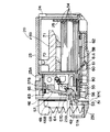
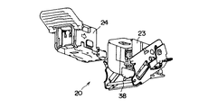
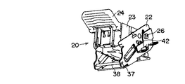
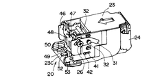
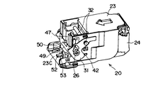
図2は、一実施の形態にかかる電動ステープラの概略構成を示す。図2において20は電動ステープラである。この電動ステープラ20は、コピー機のスタック機構のフレームにボルトにより取り付けられて固定されるアウターケース21と、アウターケース21に上下動可能に支持されるインナーケース22と、インナーケース22に揺動可能に保持されるマガジン23と、マガジン23の内部に装着されるカートリッジケース24と、カートリッジケース24に格納されるカートリッジ25(図1参照)とを備えている。
【0018】
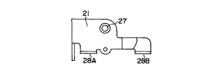
アウターケース21は、インナーケース22を内蔵するために、コの字型の平面形状を有しており、アウターケース21の側板部には、図3及び図9に示すように、ガイドピン26の取付穴27が開口されており、外側に突出する突出片28A、28Bが形成されている。突出片28A、28Bはネジ止め穴を備えている。
【0019】
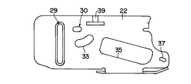
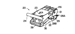
図4は、インナーケース22の側面形状を示している。インナーケース22もアウターケース21と同様にコの字型の平面形状を有する板体からなり、側板部にガイドピン26が挿入されるガイド溝29が形成されている。30はリンク31(図10参照)を揺動させるピン32を案内する穴、33はマガジン23を傾けるとき(図8参照)にピン42の動きを許容する穴、35はカートリッジケース24をマガジン23の奥部に付勢するバネ36(図9参照)を配設する穴、37はバネ36の一端を掛止された固定軸38(図7、8参照)を通す穴である。バネ36に掛止された固定軸38はカートリッジケース24の後端部突出部位34に係合してカートリッジケース24をマガジン23の奥部に付勢する。39は、リンク31の揺動領域を規制するために内側に突出する突起である。
【0020】
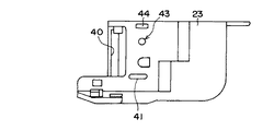
図5は、マガジン23の側面形状を示す。マガジン23はカートリッジケース24を保持するように矩形状の筒状形態を有する。マガジン23の前端部近傍には、ガイド溝29と対応するガイド溝40が形成されており、ガイド溝40にガイドピン26が上下動可能に挿入される。41はカートリッジケース24の送り爪操作用の軸42(図10、11参照)を通す穴、43はピン32を通す穴、44はリンク31の揺動を規制する突起である。
【0021】
マガジン23の前壁部45(図10、11参照)には、フォーミングプレート46の上下動をガイドするガイド溝47が形成されている。又、マガジン23の前端部には、フォーミングプレート46とドライバー48とを案内する通路49が形成されている。通路49の更に前端部側には縦壁部50が形成され、縦壁部50には、カートリッジケース24のカバー51の突起52を通す穴53が形成されている。
【0022】
図6はカートリッジケース24の側面形状を示す。カートリッジケース24は外層ケース24Aとベース24Bとで構成される。外層ケース24Aはカートリッジ25の上部を覆い、カートリッジ25の下部がベース24Bにより支持されるように、底のあいた箱形の形状を有している。
【0023】
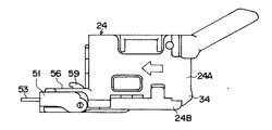
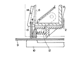
また、図1に示すように、外層ケース24Aとベース24Bとの間であってカバー51側の部分には、ステープルシート54を通すための通路55が形成されている。このカートリッジケース24の通路55を構成する通路形成部56の上部には、ステープルシート54の送り方向前端部に位置するステープルに接触する揺動部材としてのセンサ57が配設されている。
【0024】
なお、給送路としての通路55は、ベース24Bに保持される下部プレート56と上部プレート80との間に形成される。58は下部プレート56上にあって前後にスライドするプレートであり、プレート58の前端部左右側縁部にフック部59(図6参照)が形成され、プレート58の中央部にステープルシート54の送り爪60が保持されている。送り爪60は左右両側に矩形状の突出部を有し、その突出部が保持用の突起61の凹部61Aに保持されている。送り爪60はバネ62によりステープルシート54の送り方向に付勢され、プレート58はフック部59が軸42に押されてステープルシート54の送り方向と逆方向に付勢されている。
【0025】
軸42は、図11に示すように、ピン32がガイドピン26に対して相対的に上昇するときにリンク31が揺動することにより、リンク31に押されてバネ62を圧縮する方向に移動する。これにより、フック部59が後退し、プレート58が後退する。このプレート58の後退により、送り爪60が後方のステープルとステープルとが連結される凹部にかみ合う。そして、図10に示すように、ピン32がガイドピン26側に向けて相対的に下降するときに、リンク31による軸42の押圧が解除される一方、バネ62の弾性力によりプレート58が通路55の出口側に移動し、送り爪60がステープルシート54をステープル1本分前方に送り出す。
【0026】
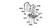
センサ57は、この送り出されるステープルシート54の先端に位置するステープルに接触して、ステープルシート54の有無を検出する。即ち、センサ57の一端部57Aはステープルシート54が送られてくる通路55の出口側の端部に臨んでおり、センサ57の他端部57Bは、透過型のインタラプタ63の間を通過するように延びている。センサ57の揺動支点57Cはインタラプタ63側よりも通路55側に片寄らせた位置に設けられており、センサ57の揺動支点57Cから一端部57Aまでの距離よりも、センサ57の揺動支点57Cから他端部57Bまでの距離が、長くなるようになっている。
【0027】
即ち、ステープルシート54の送り量はステープル1本分程度であるために、センサ57の一端部57Aの揺動時の円弧長は、僅かなものであるが、揺動支点57Cが一端部57A側に変位しており、揺動支点57Cと一端部57Aの長さに対して、揺動支点57Cと他端部57Bの長さが4〜6倍程度の長さをもっている。
【0028】
このため、ステープルシート54の送り量がステープル1本分の距離であっても、センサ57の他端部57Bの揺動時にはステープル4本〜6本分に相当する円弧長を得ることができる。これによって、他端部57Bがインタラプタ63をオンオフさせることに充分な移動量を確保でき、正確にステープルシート54の送りを検出できる。
【0029】
センサ57の一端部57Aは、ステープルシート54の先端部がフォーミングプレート46の真下に位置するときに、そのステープルシート54の先端部に位置するステープルに接触し、センサ57の他端部57Bはインタラプタ63を導通させる。センサ57の一端部57Aは、ステープルシート54の先端部がフォーミングプレート46の真下まで送られないときに、揺動支点57C近傍の突起がマガジン23の前部壁部23Bに当たって揺動が停止し、センサ57の他端部57Bがインタラプタ63を遮光して非導通とさせる。
【0030】
なお、揺動支点57Cは、センサ57の左右両側に突出する軸部57E(図13参照)により形成され、この軸部57Eはマガジン23の左右両側へ基部内面に形成された凹部に保持されている。
【0031】
また、センサ57の中間部の突起57Dには、一端がマガジン23の仕切壁部23Aに支持されたバネ64の他端が取り付けられ、バネ64はセンサ57の一端部57Aをステープルシート54の送り方向と反対側に付勢している。
【0032】
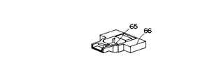
インタラプタ63は、図12、図15に示す基板65の裏面に取り付けられている。基板65はホルダー66に保持されている。基板65にはインタラプタ63以外のその他のセンサスイッチ類も取り付けられている。インタラプタ63及びその他のスイッチ類の出力信号に基づいて、電動ステープラ20の待機状態・動作状態・エラー状態等をコピー機が判断する。
【0033】
センサ57の一端部57Aの真上には、前述の通りフォーミングプレート46とドライバー48とが配設されている。図12は、フォーミングプレート46とドライバー48との組み合わせ状態を示す。フォーミングプレート46は、図13に示すように、下端部中央部にコの字型の成形用の凹部46Aが形成され、上端部両側に逆J字形状の突起46Bが一対形成されている。図12に示すように、この突起46Bの下側にドライバー48が組み付けられる。
【0034】
フォーミングプレート46の下端部はステープルをアンビル56Aと共同してコの字型に成形するものであり、フォーミングプレート46の凹部46Aは、フォーミングプレート46が最もアンビル56A側に接近しても、センサ57の一端部57Aが凹部46A内に位置し得る深さを有している。
【0035】
ドライバー48の下端部は、フォーミングプレート46と同時に下降するときに、コの字型に成形されたステープルをコピー紙の束に貫通させるために、平らに形成されているが、ドライバー48の下端部中央部には、センサ57の一端部57Aを位置させる逃げ凹部48Aが形成されている。ドライバー48の逃げ凹部48Aは、ドライバー48によりステープルをコピー紙の束に打ち込んで、図示しないクリンチャーにより、コピー紙の裏側に突出するステープルの脚部が折り曲げられるときも、センサ57の一端部57Aが位置できる深さを有している。
【0036】
フォーミングプレート46の突起46Bとマガジン23の前側の水平部23Cとの間には、バネ68が装着されており、フォーミングプレート46及びドライバー48とは、バネ68によってマガジン23の水平部23Cから離間する方向に付勢されている。
【0037】
なお、カートリッジケース24の内部に格納されたカートリッジ25は、押付板69の突起70、71により下方に押圧されている。
【0038】
以上述べたように、この実施の形態の電動ステープラ20は、真直状のステープルを並列に並べてシート状に接着してなるステープルシート54を、ステープルに対して直交方向に送る通路55を有し、この通路55のステープルシート54の送り方向のアンビル56A(図13参照)に、ステープルをコの字型に成型するフォーミングプレート46と、コの字型に成型されたステープルを押し出してコピー紙に差し込むためのドライバー48とが配置され、フォーミングプレート46とドライバー48とをステープル54Aを横断するように移動させて、通路55の下方に位置するコピー紙に成型済みステープルを差し込む構成とされている。
【0039】
そして、通路55のアンビル56Aの上方であってフォーミングプレート46が成型前に待機する位置に、一端部57Aがステープルシート54の送り方向先端部のステープルに接触し、他端部57Bがインタラプタ63(検出素子)をオンオフさせるセンサ57(揺動部材)を設けている。
【0040】
更に、このセンサ57の揺動支点57Cを、通路55のステープルシート54側に片寄らせて位置するように設け、フォーミングプレート46とドライバー48にセンサ57の一端部の揺動を許容する凹部46A、48A(開口部)を設けたことを特徴とする。
【0041】
このような、電動ステープラ20のステープルシート検出機構によれば、ステープルシート54を送る通路55の近接部位にセンサ57の揺動支点57Cを設けるので、他端部57B側の揺動時の円弧長が大きくなり、インタラプタ63を明確にオンオフでき、検出精度が向上する。
【0042】
また、フォーミングプレート46とドライバー48にセンサ57の揺動を許容する凹部46A、48Aを形成しているので、センサ57がフォーミングプレート46若しくはドライバー48と接触して摩耗することが防止され、耐久性が向上する。更に、フォーミングプレート46とドライバー48の近傍であって、カートリッジ25側にセンサ57を配設するので、小型化が促進される。
【0043】
【発明の効果】
本発明の電動ステープラのステープルシート検出機構によれば、揺動部材の揺動支点を、ステープルシート当接側であって検出素子から遠い位置に設けるので、他端側の揺動時の回動角度が大きくなり、検出素子を明確にオンオフでき、検出精度が向上する。更に、前記構造により、てこ比を大きくとっても検出機構の小型化が可能となり、同時にステープラの小型化が促進される。
【0044】
また、フォーミングプレートとドライバーに揺動部材の揺動を許容する開口部を形成しているので、揺動部材がフォーミングプレート若しくはドライバーと接触して摩耗することが防止され、耐久性が向上する。
【図面の簡単な説明】
【図1】本発明の実施の形態にかかる電動ステープラのマガジン及びカートリッジケースの断面構成を示す図。
【図2】図1の電動ステープラの側面図。
【図3】図1のアウターケースの側面図。
【図4】図1のインナーケースの側面図。
【図5】図1のマガジンの側面図。
【図6】図1のカートリッジケースの側面図。
【図7】インナーケースを傾けてマガジン内にカートリッジケースを挿入する直前の状態を示す斜視図。
【図8】図7のカートリッジケースをマガジン内に装着した状態を示す斜視図。
【図9】図8の傾いた状態のマガジンをインナーケースにあわせて水平にした状態の斜視図。
【図10】図1のマガジンの上縁部をガイドピンに接近させて、フォーミングプレートとドライバーをステープルシートの通路から離れた待機位置に位置させた状態の電動ステープラの斜視図。
【図11】図1のマガジンの上縁部をガイドピンから遠ざけて、フォーミングプレートとドライバーをステープルシートの通路に位置させた状態の電動ステープラの斜視図。
【図12】フォーミングプレートとドライバー及びリンクの組み合わせ状態を示す電動ステープラの斜視図。
【図13】フォーミングプレートとセンサ及びステープルシートの先端部の位置関係を示す斜視図。
【図14】図13のドライバーの斜視図。
【図15】マガジンの通路上方に配置される基板を取り付けるホルダーの斜視図。
【図16】従来のカートリッジケースの断面図。
【図17】従来からのカートリッジの斜視図。
【図18】従来のカートリッジケースにおいてステープルセンサとステープルの位置関係を示す拡大図。
【符号の説明】
20 電動ステープラ
21 アウターケース
22 インナーケース
23 マガジン
24 カートリッジケース
25 カートリッジ
46 フォーミングプレート
46A 凹部
48 ドライバー
48A 凹部
54 ステープルシート
55 ステープルシートを送る通路
56A アンビル(通路の先端部)
57 センサ
57A センサの一端部
57B センサの他端部
57C 揺動支点
63 インタラプタ[0001]
BACKGROUND OF THE INVENTION
The present invention relates to a staple detection mechanism of an electric stapler, and more particularly, when a staple is separated from a staple sheet formed into a sheet shape and formed into a U-shape for binding copy paper or the like. The present invention relates to a staple detection mechanism that detects whether a staple sheet is positioned at a forming position of the mechanism.
[0002]
[Prior art]
2. Description of the Related Art Conventionally, some stackers such as copy machines are provided with an electric stapler.
[0003]
FIG. 16 shows a schematic configuration of the electric stapler 1. The electric stapler 1 uses a staple sheet 3 (see FIG. 17) in which a large number of
[0004]
The
[0005]
The
[0006]
The forming
[0007]
The electric stapler 1 is a contact-type staple (not shown) that detects by contacting the
[0008]
This staple sensor is disposed on the side of the
[0009]
The staple sensor extends so as to cross the trajectory when the forming
[0010]
[Problems to be solved by the invention]
By the way, in the conventional electric stapler, when the
[0011]
However, since the contact end of the staple sensor 13 is away from the swing fulcrum of the staple sensor 13, the swing angle is small. For this reason, there is a possibility that the other end of the staple sensor 13 does not have a sufficient moving distance for switching a signal of a photo interrupter (not shown) that faces the staple sensor 13 and outputs an error signal.
[0012]
For this reason, when the distance from the fulcrum of the staple sensor 13 to the other end is increased and the lever ratio between the contact end and the other end is changed, the entire apparatus becomes larger and mounted on a copying machine or the like. The properties were also unfavorable.
[0013]
Furthermore, when the forming
[0014]
The staple detection mechanism of the electric stapler according to the present invention has been made in view of such a problem. The mechanism for detecting the leading end portion of the staple sheet is miniaturized, the detection accuracy is improved, and the durability is improved. For the purpose.
[0015]
[Means for Solving the Problems]
In order to solve the above-mentioned problems, the invention according to claim 1 is a forming method in which the staple of the staple sheet is formed in a U-shape above the leading end portion in the feeding direction of the feeding path of the staple sheet stored in the cartridge and sent out. A plate and a driver that is positioned on the front side of the forming plate and that inserts a staple formed in a U-shape into copy paper is disposed in a direction orthogonal to the feeding path, and the forming plate and the driver A detecting element for detecting that the staple sheet is positioned in the feeding path when the sheet is moved with respect to the feeding path, and the detecting element is located above the feeding path and the forming In the staple sheet detection mechanism of the electric stapler arranged behind the plate ,
A swing member is provided on the rear side of the forming plate,
One end of the swing member is positioned on the front side of the driver through the lower side of the forming plate and the driver, and always presses and urges the front surface of the leading staple of the staple sheet, and the other end of the swing member is The detection element is turned on and off by swinging the swing member,
The swing fulcrum of the swing member is positioned behind the forming plate and toward the feeding path ,
The forming plate and the driver are provided with relief recesses that allow the swinging member to swing .
[0016]
DETAILED DESCRIPTION OF THE INVENTION
Hereinafter, an embodiment of a staple sheet detection mechanism of an electric stapler according to the present invention will be described with reference to the drawings.
[0017]
FIG. 2 shows a schematic configuration of the electric stapler according to the embodiment. In FIG. 2, 20 is an electric stapler. The
[0018]
The
[0019]
FIG. 4 shows the side shape of the
[0020]
FIG. 5 shows a side shape of the
[0021]
A
[0022]
FIG. 6 shows the side shape of the
[0023]
As shown in FIG. 1, a
[0024]
The
[0025]
As shown in FIG. 11, the
[0026]
The
[0027]
That is, since the feed amount of the
[0028]
For this reason, even if the feed amount of the
[0029]
One
[0030]
The
[0031]
Further, the other end of the
[0032]
The
[0033]
As described above, the forming
[0034]
The lower end portion of the forming
[0035]
The lower end portion of the
[0036]
A
[0037]
The cartridge 25 stored inside the
[0038]
As described above, the
[0039]
Then, at a position above the
[0040]
Further, a
[0041]
According to the staple sheet detection mechanism of the
[0042]
In addition, since the
[0043]
【Effect of the invention】
According to the staple sheet detection mechanism of the electric stapler of the present invention, the swing support point of the swing member is provided on the staple sheet contact side and at a position far from the detection element. The angle increases, the detection element can be clearly turned on and off, and the detection accuracy is improved. Further, the structure allows the detection mechanism to be downsized even when the lever ratio is large, and at the same time, downsizing of the stapler is promoted.
[0044]
In addition, since the opening for allowing the swinging member to swing is formed in the forming plate and the driver, the swinging member is prevented from coming into contact with the forming plate or the driver, and durability is improved.
[Brief description of the drawings]
FIG. 1 is a diagram showing a cross-sectional configuration of a magazine and a cartridge case of an electric stapler according to an embodiment of the present invention.
FIG. 2 is a side view of the electric stapler of FIG.
3 is a side view of the outer case of FIG. 1. FIG.
4 is a side view of the inner case of FIG. 1. FIG.
FIG. 5 is a side view of the magazine of FIG.
6 is a side view of the cartridge case of FIG. 1. FIG.
FIG. 7 is a perspective view showing a state immediately before an inner case is inclined and a cartridge case is inserted into a magazine.
8 is a perspective view showing a state where the cartridge case of FIG. 7 is mounted in a magazine.
9 is a perspective view of the tilted magazine of FIG. 8 in a horizontal state in accordance with the inner case.
10 is a perspective view of the electric stapler in a state where the upper edge portion of the magazine in FIG. 1 is brought close to the guide pin and the forming plate and the driver are positioned at a standby position away from the path of the staple sheet.
11 is a perspective view of the electric stapler in a state where the upper edge of the magazine in FIG. 1 is moved away from the guide pin and the forming plate and the driver are positioned in the path of the staple sheet.
FIG. 12 is a perspective view of an electric stapler showing a combined state of a forming plate, a driver, and a link.
FIG. 13 is a perspective view showing a positional relationship among a forming plate, a sensor, and a leading end portion of a staple sheet.
14 is a perspective view of the driver of FIG.
FIG. 15 is a perspective view of a holder for attaching a substrate disposed above the passage of the magazine.
FIG. 16 is a cross-sectional view of a conventional cartridge case.
FIG. 17 is a perspective view of a conventional cartridge.
FIG. 18 is an enlarged view showing a positional relationship between a staple sensor and staples in a conventional cartridge case.
[Explanation of symbols]
20
57
Claims (1)
前記フォーミングプレートの後側に揺動部材を設け、
この揺動部材の一端が前記フォーミングプレートおよびドライバの下側を通って前記ドライバの前側に位置するとともに前記ステープルシートの先頭のステープルの前面を常時押圧付勢し、該揺動部材の他端が該揺動部材の揺動によって前記検出素子をオンオフさせ、
該揺動部材の揺動支点を、前記フォーミングプレートの後側であって前記給送路側に片寄らせて位置させ、
前記フォーミングプレートと前記ドライバーに、前記揺動部材の揺動を許容する逃げ凹部を設けたことを特徴とする電動ステープラのステープル検出機構。A forming plate for forming staples of the staple sheet into a U-shape above the leading end portion in the feeding direction of the feeding path of the staple sheet stored and sent out in the cartridge, and located on the front side of the forming plate and A driver that inserts the staple formed into a letter shape into a copy paper is disposed in a direction orthogonal to the feeding path, and when the forming plate and the driver are moved relative to the feeding path, A staple sheet detecting mechanism for an electric stapler having a detecting element for detecting that the staple sheet is positioned in the feeding path, and the detecting element is disposed above the feeding path and behind the forming plate. In
A swing member is provided on the rear side of the forming plate,
One end of the swing member is positioned on the front side of the driver through the lower side of the forming plate and the driver, and always presses and urges the front surface of the leading staple of the staple sheet, and the other end of the swing member is The detection element is turned on and off by swinging the swing member,
The swing fulcrum of the swing member is positioned behind the forming plate and toward the feeding path ,
A staple detection mechanism for an electric stapler, wherein the forming plate and the driver are provided with relief recesses that allow the swinging member to swing .
Priority Applications (8)
| Application Number | Priority Date | Filing Date | Title |
|---|---|---|---|
| JP2001273328A JP4857504B2 (en) | 2001-09-10 | 2001-09-10 | Electric stapler staple detection mechanism |
| TW091120575A TWI223619B (en) | 2001-09-10 | 2002-09-10 | Staple detecting mechanism of electric stapler |
| US10/488,986 US7048165B2 (en) | 2001-09-10 | 2002-09-10 | Staple detecting mechanism of electric stapler |
| PCT/JP2002/009209 WO2003022538A1 (en) | 2001-09-10 | 2002-09-10 | Staple detection mechanism of electric stapler |
| EP02767928A EP1426155B1 (en) | 2001-09-10 | 2002-09-10 | Staple detection mechanism of electric stapler |
| DE60231518T DE60231518D1 (en) | 2001-09-10 | 2002-09-10 | BRACKET MECHANISM FOR ELECTRIC STORAGE |
| KR10-2004-7003412A KR100538364B1 (en) | 2001-09-10 | 2002-09-10 | Staple detection mechanism of electric stapler |
| CNB028175956A CN100372664C (en) | 2001-09-10 | 2002-09-10 | Staple detection mechanism of electric stapler |
Applications Claiming Priority (1)
| Application Number | Priority Date | Filing Date | Title |
|---|---|---|---|
| JP2001273328A JP4857504B2 (en) | 2001-09-10 | 2001-09-10 | Electric stapler staple detection mechanism |
Publications (2)
| Publication Number | Publication Date |
|---|---|
| JP2003080503A JP2003080503A (en) | 2003-03-19 |
| JP4857504B2 true JP4857504B2 (en) | 2012-01-18 |
Family
ID=19098559
Family Applications (1)
| Application Number | Title | Priority Date | Filing Date |
|---|---|---|---|
| JP2001273328A Expired - Lifetime JP4857504B2 (en) | 2001-09-10 | 2001-09-10 | Electric stapler staple detection mechanism |
Country Status (8)
| Country | Link |
|---|---|
| US (1) | US7048165B2 (en) |
| EP (1) | EP1426155B1 (en) |
| JP (1) | JP4857504B2 (en) |
| KR (1) | KR100538364B1 (en) |
| CN (1) | CN100372664C (en) |
| DE (1) | DE60231518D1 (en) |
| TW (1) | TWI223619B (en) |
| WO (1) | WO2003022538A1 (en) |
Families Citing this family (369)
| Publication number | Priority date | Publication date | Assignee | Title |
|---|---|---|---|---|
| JP2003025248A (en) * | 2001-07-10 | 2003-01-29 | Max Co Ltd | Feeding mechanism for sheet staple |
| WO2004033157A1 (en) * | 2002-10-09 | 2004-04-22 | Max Co., Ltd. | Staple case |
| US7748587B2 (en) | 2003-02-07 | 2010-07-06 | Max Kabushiki Kaisha | Staple refill, stapler and cartridge |
| KR101044218B1 (en) * | 2003-02-14 | 2011-06-29 | 막스 가부시키가이샤 | Stapler |
| US20070084897A1 (en) | 2003-05-20 | 2007-04-19 | Shelton Frederick E Iv | Articulating surgical stapling instrument incorporating a two-piece e-beam firing mechanism |
| US9060770B2 (en) | 2003-05-20 | 2015-06-23 | Ethicon Endo-Surgery, Inc. | Robotically-driven surgical instrument with E-beam driver |
| US11896225B2 (en) | 2004-07-28 | 2024-02-13 | Cilag Gmbh International | Staple cartridge comprising a pan |
| US8215531B2 (en) | 2004-07-28 | 2012-07-10 | Ethicon Endo-Surgery, Inc. | Surgical stapling instrument having a medical substance dispenser |
| US9237891B2 (en) | 2005-08-31 | 2016-01-19 | Ethicon Endo-Surgery, Inc. | Robotically-controlled surgical stapling devices that produce formed staples having different lengths |
| US11484312B2 (en) | 2005-08-31 | 2022-11-01 | Cilag Gmbh International | Staple cartridge comprising a staple driver arrangement |
| US11246590B2 (en) | 2005-08-31 | 2022-02-15 | Cilag Gmbh International | Staple cartridge including staple drivers having different unfired heights |
| US10159482B2 (en) | 2005-08-31 | 2018-12-25 | Ethicon Llc | Fastener cartridge assembly comprising a fixed anvil and different staple heights |
| US7669746B2 (en) | 2005-08-31 | 2010-03-02 | Ethicon Endo-Surgery, Inc. | Staple cartridges for forming staples having differing formed staple heights |
| US7934630B2 (en) | 2005-08-31 | 2011-05-03 | Ethicon Endo-Surgery, Inc. | Staple cartridges for forming staples having differing formed staple heights |
| US20070106317A1 (en) | 2005-11-09 | 2007-05-10 | Shelton Frederick E Iv | Hydraulically and electrically actuated articulation joints for surgical instruments |
| US11224427B2 (en) | 2006-01-31 | 2022-01-18 | Cilag Gmbh International | Surgical stapling system including a console and retraction assembly |
| US20120292367A1 (en) | 2006-01-31 | 2012-11-22 | Ethicon Endo-Surgery, Inc. | Robotically-controlled end effector |
| US11278279B2 (en) | 2006-01-31 | 2022-03-22 | Cilag Gmbh International | Surgical instrument assembly |
| US8708213B2 (en) | 2006-01-31 | 2014-04-29 | Ethicon Endo-Surgery, Inc. | Surgical instrument having a feedback system |
| US8820603B2 (en) | 2006-01-31 | 2014-09-02 | Ethicon Endo-Surgery, Inc. | Accessing data stored in a memory of a surgical instrument |
| US20110024477A1 (en) | 2009-02-06 | 2011-02-03 | Hall Steven G | Driven Surgical Stapler Improvements |
| US8186555B2 (en) | 2006-01-31 | 2012-05-29 | Ethicon Endo-Surgery, Inc. | Motor-driven surgical cutting and fastening instrument with mechanical closure system |
| US7845537B2 (en) | 2006-01-31 | 2010-12-07 | Ethicon Endo-Surgery, Inc. | Surgical instrument having recording capabilities |
| US20110290856A1 (en) | 2006-01-31 | 2011-12-01 | Ethicon Endo-Surgery, Inc. | Robotically-controlled surgical instrument with force-feedback capabilities |
| US11793518B2 (en) | 2006-01-31 | 2023-10-24 | Cilag Gmbh International | Powered surgical instruments with firing system lockout arrangements |
| US7753904B2 (en) | 2006-01-31 | 2010-07-13 | Ethicon Endo-Surgery, Inc. | Endoscopic surgical instrument with a handle that can articulate with respect to the shaft |
| US8992422B2 (en) | 2006-03-23 | 2015-03-31 | Ethicon Endo-Surgery, Inc. | Robotically-controlled endoscopic accessory channel |
| JP5013933B2 (en) * | 2006-04-18 | 2012-08-29 | ホリゾン・インターナショナル株式会社 | Wire binding machine |
| US8322455B2 (en) | 2006-06-27 | 2012-12-04 | Ethicon Endo-Surgery, Inc. | Manually driven surgical cutting and fastening instrument |
| US10568652B2 (en) | 2006-09-29 | 2020-02-25 | Ethicon Llc | Surgical staples having attached drivers of different heights and stapling instruments for deploying the same |
| US8652120B2 (en) | 2007-01-10 | 2014-02-18 | Ethicon Endo-Surgery, Inc. | Surgical instrument with wireless communication between control unit and sensor transponders |
| US11291441B2 (en) | 2007-01-10 | 2022-04-05 | Cilag Gmbh International | Surgical instrument with wireless communication between control unit and remote sensor |
| US8684253B2 (en) | 2007-01-10 | 2014-04-01 | Ethicon Endo-Surgery, Inc. | Surgical instrument with wireless communication between a control unit of a robotic system and remote sensor |
| US20080169332A1 (en) | 2007-01-11 | 2008-07-17 | Shelton Frederick E | Surgical stapling device with a curved cutting member |
| US11039836B2 (en) | 2007-01-11 | 2021-06-22 | Cilag Gmbh International | Staple cartridge for use with a surgical stapling instrument |
| US7673782B2 (en) | 2007-03-15 | 2010-03-09 | Ethicon Endo-Surgery, Inc. | Surgical stapling instrument having a releasable buttress material |
| US8931682B2 (en) | 2007-06-04 | 2015-01-13 | Ethicon Endo-Surgery, Inc. | Robotically-controlled shaft based rotary drive systems for surgical instruments |
| US11857181B2 (en) | 2007-06-04 | 2024-01-02 | Cilag Gmbh International | Robotically-controlled shaft based rotary drive systems for surgical instruments |
| US7753245B2 (en) | 2007-06-22 | 2010-07-13 | Ethicon Endo-Surgery, Inc. | Surgical stapling instruments |
| US11849941B2 (en) | 2007-06-29 | 2023-12-26 | Cilag Gmbh International | Staple cartridge having staple cavities extending at a transverse angle relative to a longitudinal cartridge axis |
| JP5410110B2 (en) | 2008-02-14 | 2014-02-05 | エシコン・エンド−サージェリィ・インコーポレイテッド | Surgical cutting / fixing instrument with RF electrode |
| US7819298B2 (en) | 2008-02-14 | 2010-10-26 | Ethicon Endo-Surgery, Inc. | Surgical stapling apparatus with control features operable with one hand |
| US9179912B2 (en) | 2008-02-14 | 2015-11-10 | Ethicon Endo-Surgery, Inc. | Robotically-controlled motorized surgical cutting and fastening instrument |
| US7866527B2 (en) | 2008-02-14 | 2011-01-11 | Ethicon Endo-Surgery, Inc. | Surgical stapling apparatus with interlockable firing system |
| US8758391B2 (en) | 2008-02-14 | 2014-06-24 | Ethicon Endo-Surgery, Inc. | Interchangeable tools for surgical instruments |
| US8573465B2 (en) | 2008-02-14 | 2013-11-05 | Ethicon Endo-Surgery, Inc. | Robotically-controlled surgical end effector system with rotary actuated closure systems |
| US8636736B2 (en) | 2008-02-14 | 2014-01-28 | Ethicon Endo-Surgery, Inc. | Motorized surgical cutting and fastening instrument |
| US9770245B2 (en) | 2008-02-15 | 2017-09-26 | Ethicon Llc | Layer arrangements for surgical staple cartridges |
| US11648005B2 (en) | 2008-09-23 | 2023-05-16 | Cilag Gmbh International | Robotically-controlled motorized surgical instrument with an end effector |
| US9386983B2 (en) | 2008-09-23 | 2016-07-12 | Ethicon Endo-Surgery, Llc | Robotically-controlled motorized surgical instrument |
| US9005230B2 (en) | 2008-09-23 | 2015-04-14 | Ethicon Endo-Surgery, Inc. | Motorized surgical instrument |
| US8210411B2 (en) | 2008-09-23 | 2012-07-03 | Ethicon Endo-Surgery, Inc. | Motor-driven surgical cutting instrument |
| US8608045B2 (en) | 2008-10-10 | 2013-12-17 | Ethicon Endo-Sugery, Inc. | Powered surgical cutting and stapling apparatus with manually retractable firing system |
| US8517239B2 (en) | 2009-02-05 | 2013-08-27 | Ethicon Endo-Surgery, Inc. | Surgical stapling instrument comprising a magnetic element driver |
| JP2012517287A (en) | 2009-02-06 | 2012-08-02 | エシコン・エンド−サージェリィ・インコーポレイテッド | Improvement of driven surgical stapler |
| EP2255935B1 (en) * | 2009-05-28 | 2012-06-20 | Max Co., Ltd. | Electric stapler |
| US8851354B2 (en) | 2009-12-24 | 2014-10-07 | Ethicon Endo-Surgery, Inc. | Surgical cutting instrument that analyzes tissue thickness |
| US8220688B2 (en) | 2009-12-24 | 2012-07-17 | Ethicon Endo-Surgery, Inc. | Motor-driven surgical cutting instrument with electric actuator directional control assembly |
| US8783543B2 (en) | 2010-07-30 | 2014-07-22 | Ethicon Endo-Surgery, Inc. | Tissue acquisition arrangements and methods for surgical stapling devices |
| US9629814B2 (en) | 2010-09-30 | 2017-04-25 | Ethicon Endo-Surgery, Llc | Tissue thickness compensator configured to redistribute compressive forces |
| US11812965B2 (en) | 2010-09-30 | 2023-11-14 | Cilag Gmbh International | Layer of material for a surgical end effector |
| US9566061B2 (en) | 2010-09-30 | 2017-02-14 | Ethicon Endo-Surgery, Llc | Fastener cartridge comprising a releasably attached tissue thickness compensator |
| US10945731B2 (en) | 2010-09-30 | 2021-03-16 | Ethicon Llc | Tissue thickness compensator comprising controlled release and expansion |
| US11298125B2 (en) | 2010-09-30 | 2022-04-12 | Cilag Gmbh International | Tissue stapler having a thickness compensator |
| US11925354B2 (en) | 2010-09-30 | 2024-03-12 | Cilag Gmbh International | Staple cartridge comprising staples positioned within a compressible portion thereof |
| US9113865B2 (en) | 2010-09-30 | 2015-08-25 | Ethicon Endo-Surgery, Inc. | Staple cartridge comprising a layer |
| US9320523B2 (en) | 2012-03-28 | 2016-04-26 | Ethicon Endo-Surgery, Llc | Tissue thickness compensator comprising tissue ingrowth features |
| US9211120B2 (en) | 2011-04-29 | 2015-12-15 | Ethicon Endo-Surgery, Inc. | Tissue thickness compensator comprising a plurality of medicaments |
| US8695866B2 (en) | 2010-10-01 | 2014-04-15 | Ethicon Endo-Surgery, Inc. | Surgical instrument having a power control circuit |
| AU2012250197B2 (en) | 2011-04-29 | 2017-08-10 | Ethicon Endo-Surgery, Inc. | Staple cartridge comprising staples positioned within a compressible portion thereof |
| US11207064B2 (en) | 2011-05-27 | 2021-12-28 | Cilag Gmbh International | Automated end effector component reloading system for use with a robotic system |
| US9072535B2 (en) | 2011-05-27 | 2015-07-07 | Ethicon Endo-Surgery, Inc. | Surgical stapling instruments with rotatable staple deployment arrangements |
| US9220502B2 (en) | 2011-12-28 | 2015-12-29 | Covidien Lp | Staple formation recognition for a surgical device |
| US9044230B2 (en) | 2012-02-13 | 2015-06-02 | Ethicon Endo-Surgery, Inc. | Surgical cutting and fastening instrument with apparatus for determining cartridge and firing motion status |
| RU2639857C2 (en) | 2012-03-28 | 2017-12-22 | Этикон Эндо-Серджери, Инк. | Tissue thickness compensator containing capsule for medium with low pressure |
| MX353040B (en) | 2012-03-28 | 2017-12-18 | Ethicon Endo Surgery Inc | Retainer assembly including a tissue thickness compensator. |
| CN104321024B (en) | 2012-03-28 | 2017-05-24 | 伊西康内外科公司 | Tissue thickness compensator comprising a plurality of layers |
| US9101358B2 (en) | 2012-06-15 | 2015-08-11 | Ethicon Endo-Surgery, Inc. | Articulatable surgical instrument comprising a firing drive |
| US9364230B2 (en) | 2012-06-28 | 2016-06-14 | Ethicon Endo-Surgery, Llc | Surgical stapling instruments with rotary joint assemblies |
| BR112014032776B1 (en) | 2012-06-28 | 2021-09-08 | Ethicon Endo-Surgery, Inc | SURGICAL INSTRUMENT SYSTEM AND SURGICAL KIT FOR USE WITH A SURGICAL INSTRUMENT SYSTEM |
| US9289256B2 (en) | 2012-06-28 | 2016-03-22 | Ethicon Endo-Surgery, Llc | Surgical end effectors having angled tissue-contacting surfaces |
| US9282974B2 (en) | 2012-06-28 | 2016-03-15 | Ethicon Endo-Surgery, Llc | Empty clip cartridge lockout |
| US11197671B2 (en) | 2012-06-28 | 2021-12-14 | Cilag Gmbh International | Stapling assembly comprising a lockout |
| US20140001231A1 (en) | 2012-06-28 | 2014-01-02 | Ethicon Endo-Surgery, Inc. | Firing system lockout arrangements for surgical instruments |
| CN104487005B (en) | 2012-06-28 | 2017-09-08 | 伊西康内外科公司 | Empty squeeze latching member |
| US9700310B2 (en) | 2013-08-23 | 2017-07-11 | Ethicon Llc | Firing member retraction devices for powered surgical instruments |
| RU2669463C2 (en) | 2013-03-01 | 2018-10-11 | Этикон Эндо-Серджери, Инк. | Surgical instrument with soft stop |
| JP6382235B2 (en) | 2013-03-01 | 2018-08-29 | エシコン・エンド−サージェリィ・インコーポレイテッドEthicon Endo−Surgery,Inc. | Articulatable surgical instrument with a conductive path for signal communication |
| US9351726B2 (en) | 2013-03-14 | 2016-05-31 | Ethicon Endo-Surgery, Llc | Articulation control system for articulatable surgical instruments |
| US9629629B2 (en) | 2013-03-14 | 2017-04-25 | Ethicon Endo-Surgey, LLC | Control systems for surgical instruments |
| US10405857B2 (en) | 2013-04-16 | 2019-09-10 | Ethicon Llc | Powered linear surgical stapler |
| BR112015026109B1 (en) | 2013-04-16 | 2022-02-22 | Ethicon Endo-Surgery, Inc | surgical instrument |
| JP6416260B2 (en) | 2013-08-23 | 2018-10-31 | エシコン エルエルシー | Firing member retractor for a powered surgical instrument |
| US9962161B2 (en) | 2014-02-12 | 2018-05-08 | Ethicon Llc | Deliverable surgical instrument |
| BR112016021943B1 (en) | 2014-03-26 | 2022-06-14 | Ethicon Endo-Surgery, Llc | SURGICAL INSTRUMENT FOR USE BY AN OPERATOR IN A SURGICAL PROCEDURE |
| US20150272557A1 (en) | 2014-03-26 | 2015-10-01 | Ethicon Endo-Surgery, Inc. | Modular surgical instrument system |
| US9733663B2 (en) | 2014-03-26 | 2017-08-15 | Ethicon Llc | Power management through segmented circuit and variable voltage protection |
| BR112016023807B1 (en) | 2014-04-16 | 2022-07-12 | Ethicon Endo-Surgery, Llc | CARTRIDGE SET OF FASTENERS FOR USE WITH A SURGICAL INSTRUMENT |
| BR112016023698B1 (en) | 2014-04-16 | 2022-07-26 | Ethicon Endo-Surgery, Llc | FASTENER CARTRIDGE FOR USE WITH A SURGICAL INSTRUMENT |
| US10299792B2 (en) | 2014-04-16 | 2019-05-28 | Ethicon Llc | Fastener cartridge comprising non-uniform fasteners |
| US20150297223A1 (en) | 2014-04-16 | 2015-10-22 | Ethicon Endo-Surgery, Inc. | Fastener cartridges including extensions having different configurations |
| JP6612256B2 (en) | 2014-04-16 | 2019-11-27 | エシコン エルエルシー | Fastener cartridge with non-uniform fastener |
| US11311294B2 (en) | 2014-09-05 | 2022-04-26 | Cilag Gmbh International | Powered medical device including measurement of closure state of jaws |
| BR112017004361B1 (en) | 2014-09-05 | 2023-04-11 | Ethicon Llc | ELECTRONIC SYSTEM FOR A SURGICAL INSTRUMENT |
| US9737301B2 (en) | 2014-09-05 | 2017-08-22 | Ethicon Llc | Monitoring device degradation based on component evaluation |
| US10105142B2 (en) | 2014-09-18 | 2018-10-23 | Ethicon Llc | Surgical stapler with plurality of cutting elements |
| CN107427300B (en) | 2014-09-26 | 2020-12-04 | 伊西康有限责任公司 | Surgical suture buttress and buttress material |
| US11523821B2 (en) | 2014-09-26 | 2022-12-13 | Cilag Gmbh International | Method for creating a flexible staple line |
| US10076325B2 (en) | 2014-10-13 | 2018-09-18 | Ethicon Llc | Surgical stapling apparatus comprising a tissue stop |
| US9924944B2 (en) | 2014-10-16 | 2018-03-27 | Ethicon Llc | Staple cartridge comprising an adjunct material |
| US11141153B2 (en) | 2014-10-29 | 2021-10-12 | Cilag Gmbh International | Staple cartridges comprising driver arrangements |
| US10517594B2 (en) | 2014-10-29 | 2019-12-31 | Ethicon Llc | Cartridge assemblies for surgical staplers |
| US9844376B2 (en) | 2014-11-06 | 2017-12-19 | Ethicon Llc | Staple cartridge comprising a releasable adjunct material |
| US10736636B2 (en) | 2014-12-10 | 2020-08-11 | Ethicon Llc | Articulatable surgical instrument system |
| RU2703684C2 (en) | 2014-12-18 | 2019-10-21 | ЭТИКОН ЭНДО-СЕРДЖЕРИ, ЭлЭлСи | Surgical instrument with anvil which is selectively movable relative to staple cartridge around discrete fixed axis |
| US9844374B2 (en) | 2014-12-18 | 2017-12-19 | Ethicon Llc | Surgical instrument systems comprising an articulatable end effector and means for adjusting the firing stroke of a firing member |
| US9987000B2 (en) | 2014-12-18 | 2018-06-05 | Ethicon Llc | Surgical instrument assembly comprising a flexible articulation system |
| US9844375B2 (en) | 2014-12-18 | 2017-12-19 | Ethicon Llc | Drive arrangements for articulatable surgical instruments |
| US10085748B2 (en) | 2014-12-18 | 2018-10-02 | Ethicon Llc | Locking arrangements for detachable shaft assemblies with articulatable surgical end effectors |
| US9968355B2 (en) | 2014-12-18 | 2018-05-15 | Ethicon Llc | Surgical instruments with articulatable end effectors and improved firing beam support arrangements |
| US11154301B2 (en) | 2015-02-27 | 2021-10-26 | Cilag Gmbh International | Modular stapling assembly |
| US9993248B2 (en) | 2015-03-06 | 2018-06-12 | Ethicon Endo-Surgery, Llc | Smart sensors with local signal processing |
| US10441279B2 (en) | 2015-03-06 | 2019-10-15 | Ethicon Llc | Multiple level thresholds to modify operation of powered surgical instruments |
| JP2020121162A (en) | 2015-03-06 | 2020-08-13 | エシコン エルエルシーEthicon LLC | Time dependent evaluation of sensor data to determine stability element, creep element and viscoelastic element of measurement |
| US10617412B2 (en) | 2015-03-06 | 2020-04-14 | Ethicon Llc | System for detecting the mis-insertion of a staple cartridge into a surgical stapler |
| US10245033B2 (en) | 2015-03-06 | 2019-04-02 | Ethicon Llc | Surgical instrument comprising a lockable battery housing |
| US10687806B2 (en) | 2015-03-06 | 2020-06-23 | Ethicon Llc | Adaptive tissue compression techniques to adjust closure rates for multiple tissue types |
| US10548504B2 (en) | 2015-03-06 | 2020-02-04 | Ethicon Llc | Overlaid multi sensor radio frequency (RF) electrode system to measure tissue compression |
| US9901342B2 (en) | 2015-03-06 | 2018-02-27 | Ethicon Endo-Surgery, Llc | Signal and power communication system positioned on a rotatable shaft |
| US10213201B2 (en) | 2015-03-31 | 2019-02-26 | Ethicon Llc | Stapling end effector configured to compensate for an uneven gap between a first jaw and a second jaw |
| US11058425B2 (en) | 2015-08-17 | 2021-07-13 | Ethicon Llc | Implantable layers for a surgical instrument |
| US10105139B2 (en) | 2015-09-23 | 2018-10-23 | Ethicon Llc | Surgical stapler having downstream current-based motor control |
| US10238386B2 (en) | 2015-09-23 | 2019-03-26 | Ethicon Llc | Surgical stapler having motor control based on an electrical parameter related to a motor current |
| US10299878B2 (en) | 2015-09-25 | 2019-05-28 | Ethicon Llc | Implantable adjunct systems for determining adjunct skew |
| US10980539B2 (en) | 2015-09-30 | 2021-04-20 | Ethicon Llc | Implantable adjunct comprising bonded layers |
| US11890015B2 (en) | 2015-09-30 | 2024-02-06 | Cilag Gmbh International | Compressible adjunct with crossing spacer fibers |
| US10478188B2 (en) | 2015-09-30 | 2019-11-19 | Ethicon Llc | Implantable layer comprising a constricted configuration |
| US10736633B2 (en) | 2015-09-30 | 2020-08-11 | Ethicon Llc | Compressible adjunct with looping members |
| US10292704B2 (en) | 2015-12-30 | 2019-05-21 | Ethicon Llc | Mechanisms for compensating for battery pack failure in powered surgical instruments |
| US10368865B2 (en) | 2015-12-30 | 2019-08-06 | Ethicon Llc | Mechanisms for compensating for drivetrain failure in powered surgical instruments |
| US10265068B2 (en) | 2015-12-30 | 2019-04-23 | Ethicon Llc | Surgical instruments with separable motors and motor control circuits |
| US11213293B2 (en) | 2016-02-09 | 2022-01-04 | Cilag Gmbh International | Articulatable surgical instruments with single articulation link arrangements |
| BR112018016098B1 (en) | 2016-02-09 | 2023-02-23 | Ethicon Llc | SURGICAL INSTRUMENT |
| US11224426B2 (en) | 2016-02-12 | 2022-01-18 | Cilag Gmbh International | Mechanisms for compensating for drivetrain failure in powered surgical instruments |
| US10448948B2 (en) | 2016-02-12 | 2019-10-22 | Ethicon Llc | Mechanisms for compensating for drivetrain failure in powered surgical instruments |
| US10828028B2 (en) | 2016-04-15 | 2020-11-10 | Ethicon Llc | Surgical instrument with multiple program responses during a firing motion |
| US10335145B2 (en) | 2016-04-15 | 2019-07-02 | Ethicon Llc | Modular surgical instrument with configurable operating mode |
| US10426467B2 (en) | 2016-04-15 | 2019-10-01 | Ethicon Llc | Surgical instrument with detection sensors |
| US11179150B2 (en) | 2016-04-15 | 2021-11-23 | Cilag Gmbh International | Systems and methods for controlling a surgical stapling and cutting instrument |
| US10357247B2 (en) | 2016-04-15 | 2019-07-23 | Ethicon Llc | Surgical instrument with multiple program responses during a firing motion |
| US10456137B2 (en) | 2016-04-15 | 2019-10-29 | Ethicon Llc | Staple formation detection mechanisms |
| US11607239B2 (en) | 2016-04-15 | 2023-03-21 | Cilag Gmbh International | Systems and methods for controlling a surgical stapling and cutting instrument |
| US10492783B2 (en) | 2016-04-15 | 2019-12-03 | Ethicon, Llc | Surgical instrument with improved stop/start control during a firing motion |
| US20170296173A1 (en) | 2016-04-18 | 2017-10-19 | Ethicon Endo-Surgery, Llc | Method for operating a surgical instrument |
| US10363037B2 (en) | 2016-04-18 | 2019-07-30 | Ethicon Llc | Surgical instrument system comprising a magnetic lockout |
| US11317917B2 (en) | 2016-04-18 | 2022-05-03 | Cilag Gmbh International | Surgical stapling system comprising a lockable firing assembly |
| US11419606B2 (en) | 2016-12-21 | 2022-08-23 | Cilag Gmbh International | Shaft assembly comprising a clutch configured to adapt the output of a rotary firing member to two different systems |
| US10582928B2 (en) | 2016-12-21 | 2020-03-10 | Ethicon Llc | Articulation lock arrangements for locking an end effector in an articulated position in response to actuation of a jaw closure system |
| US20180168625A1 (en) | 2016-12-21 | 2018-06-21 | Ethicon Endo-Surgery, Llc | Surgical stapling instruments with smart staple cartridges |
| US11134942B2 (en) | 2016-12-21 | 2021-10-05 | Cilag Gmbh International | Surgical stapling instruments and staple-forming anvils |
| US11160551B2 (en) | 2016-12-21 | 2021-11-02 | Cilag Gmbh International | Articulatable surgical stapling instruments |
| US10568624B2 (en) | 2016-12-21 | 2020-02-25 | Ethicon Llc | Surgical instruments with jaws that are pivotable about a fixed axis and include separate and distinct closure and firing systems |
| US10675025B2 (en) | 2016-12-21 | 2020-06-09 | Ethicon Llc | Shaft assembly comprising separately actuatable and retractable systems |
| JP7010956B2 (en) | 2016-12-21 | 2022-01-26 | エシコン エルエルシー | How to staple tissue |
| US10881401B2 (en) | 2016-12-21 | 2021-01-05 | Ethicon Llc | Staple firing member comprising a missing cartridge and/or spent cartridge lockout |
| US10856868B2 (en) | 2016-12-21 | 2020-12-08 | Ethicon Llc | Firing member pin configurations |
| US10667809B2 (en) | 2016-12-21 | 2020-06-02 | Ethicon Llc | Staple cartridge and staple cartridge channel comprising windows defined therein |
| US10893864B2 (en) | 2016-12-21 | 2021-01-19 | Ethicon | Staple cartridges and arrangements of staples and staple cavities therein |
| US10898186B2 (en) | 2016-12-21 | 2021-01-26 | Ethicon Llc | Staple forming pocket arrangements comprising primary sidewalls and pocket sidewalls |
| US10813638B2 (en) | 2016-12-21 | 2020-10-27 | Ethicon Llc | Surgical end effectors with expandable tissue stop arrangements |
| CN110099619B (en) | 2016-12-21 | 2022-07-15 | 爱惜康有限责任公司 | Lockout device for surgical end effector and replaceable tool assembly |
| CN110087565A (en) | 2016-12-21 | 2019-08-02 | 爱惜康有限责任公司 | Surgical stapling system |
| US10537325B2 (en) | 2016-12-21 | 2020-01-21 | Ethicon Llc | Staple forming pocket arrangement to accommodate different types of staples |
| US20180168615A1 (en) | 2016-12-21 | 2018-06-21 | Ethicon Endo-Surgery, Llc | Method of deforming staples from two different types of staple cartridges with the same surgical stapling instrument |
| CN108621626B (en) * | 2017-03-16 | 2019-12-13 | 丰民金属工业股份有限公司 | Electric stapler |
| CN108725013A (en) * | 2017-04-19 | 2018-11-02 | 丰民金属工业股份有限公司 | Electric stapler |
| US10813639B2 (en) | 2017-06-20 | 2020-10-27 | Ethicon Llc | Closed loop feedback control of motor velocity of a surgical stapling and cutting instrument based on system conditions |
| US10980537B2 (en) | 2017-06-20 | 2021-04-20 | Ethicon Llc | Closed loop feedback control of motor velocity of a surgical stapling and cutting instrument based on measured time over a specified number of shaft rotations |
| USD879809S1 (en) | 2017-06-20 | 2020-03-31 | Ethicon Llc | Display panel with changeable graphical user interface |
| US10307170B2 (en) | 2017-06-20 | 2019-06-04 | Ethicon Llc | Method for closed loop control of motor velocity of a surgical stapling and cutting instrument |
| USD879808S1 (en) | 2017-06-20 | 2020-03-31 | Ethicon Llc | Display panel with graphical user interface |
| US10646220B2 (en) | 2017-06-20 | 2020-05-12 | Ethicon Llc | Systems and methods for controlling displacement member velocity for a surgical instrument |
| US10881396B2 (en) | 2017-06-20 | 2021-01-05 | Ethicon Llc | Surgical instrument with variable duration trigger arrangement |
| US10779820B2 (en) | 2017-06-20 | 2020-09-22 | Ethicon Llc | Systems and methods for controlling motor speed according to user input for a surgical instrument |
| US11090046B2 (en) | 2017-06-20 | 2021-08-17 | Cilag Gmbh International | Systems and methods for controlling displacement member motion of a surgical stapling and cutting instrument |
| USD890784S1 (en) | 2017-06-20 | 2020-07-21 | Ethicon Llc | Display panel with changeable graphical user interface |
| US11071554B2 (en) | 2017-06-20 | 2021-07-27 | Cilag Gmbh International | Closed loop feedback control of motor velocity of a surgical stapling and cutting instrument based on magnitude of velocity error measurements |
| US11653914B2 (en) | 2017-06-20 | 2023-05-23 | Cilag Gmbh International | Systems and methods for controlling motor velocity of a surgical stapling and cutting instrument according to articulation angle of end effector |
| US11382638B2 (en) | 2017-06-20 | 2022-07-12 | Cilag Gmbh International | Closed loop feedback control of motor velocity of a surgical stapling and cutting instrument based on measured time over a specified displacement distance |
| US11517325B2 (en) | 2017-06-20 | 2022-12-06 | Cilag Gmbh International | Closed loop feedback control of motor velocity of a surgical stapling and cutting instrument based on measured displacement distance traveled over a specified time interval |
| US10888321B2 (en) | 2017-06-20 | 2021-01-12 | Ethicon Llc | Systems and methods for controlling velocity of a displacement member of a surgical stapling and cutting instrument |
| US10881399B2 (en) | 2017-06-20 | 2021-01-05 | Ethicon Llc | Techniques for adaptive control of motor velocity of a surgical stapling and cutting instrument |
| US10993716B2 (en) | 2017-06-27 | 2021-05-04 | Ethicon Llc | Surgical anvil arrangements |
| US11266405B2 (en) | 2017-06-27 | 2022-03-08 | Cilag Gmbh International | Surgical anvil manufacturing methods |
| US10856869B2 (en) | 2017-06-27 | 2020-12-08 | Ethicon Llc | Surgical anvil arrangements |
| US20180368844A1 (en) | 2017-06-27 | 2018-12-27 | Ethicon Llc | Staple forming pocket arrangements |
| US10772629B2 (en) | 2017-06-27 | 2020-09-15 | Ethicon Llc | Surgical anvil arrangements |
| US11324503B2 (en) | 2017-06-27 | 2022-05-10 | Cilag Gmbh International | Surgical firing member arrangements |
| US10765427B2 (en) | 2017-06-28 | 2020-09-08 | Ethicon Llc | Method for articulating a surgical instrument |
| US10903685B2 (en) | 2017-06-28 | 2021-01-26 | Ethicon Llc | Surgical shaft assemblies with slip ring assemblies forming capacitive channels |
| US11259805B2 (en) | 2017-06-28 | 2022-03-01 | Cilag Gmbh International | Surgical instrument comprising firing member supports |
| US11020114B2 (en) | 2017-06-28 | 2021-06-01 | Cilag Gmbh International | Surgical instruments with articulatable end effector with axially shortened articulation joint configurations |
| US11246592B2 (en) | 2017-06-28 | 2022-02-15 | Cilag Gmbh International | Surgical instrument comprising an articulation system lockable to a frame |
| USD906355S1 (en) | 2017-06-28 | 2020-12-29 | Ethicon Llc | Display screen or portion thereof with a graphical user interface for a surgical instrument |
| US10716614B2 (en) | 2017-06-28 | 2020-07-21 | Ethicon Llc | Surgical shaft assemblies with slip ring assemblies with increased contact pressure |
| EP3420947B1 (en) | 2017-06-28 | 2022-05-25 | Cilag GmbH International | Surgical instrument comprising selectively actuatable rotatable couplers |
| US11058424B2 (en) | 2017-06-28 | 2021-07-13 | Cilag Gmbh International | Surgical instrument comprising an offset articulation joint |
| US11564686B2 (en) | 2017-06-28 | 2023-01-31 | Cilag Gmbh International | Surgical shaft assemblies with flexible interfaces |
| US10932772B2 (en) | 2017-06-29 | 2021-03-02 | Ethicon Llc | Methods for closed loop velocity control for robotic surgical instrument |
| US11007022B2 (en) | 2017-06-29 | 2021-05-18 | Ethicon Llc | Closed loop velocity control techniques based on sensed tissue parameters for robotic surgical instrument |
| US10898183B2 (en) | 2017-06-29 | 2021-01-26 | Ethicon Llc | Robotic surgical instrument with closed loop feedback techniques for advancement of closure member during firing |
| US11471155B2 (en) | 2017-08-03 | 2022-10-18 | Cilag Gmbh International | Surgical system bailout |
| US11944300B2 (en) | 2017-08-03 | 2024-04-02 | Cilag Gmbh International | Method for operating a surgical system bailout |
| US11304695B2 (en) | 2017-08-03 | 2022-04-19 | Cilag Gmbh International | Surgical system shaft interconnection |
| USD907648S1 (en) | 2017-09-29 | 2021-01-12 | Ethicon Llc | Display screen or portion thereof with animated graphical user interface |
| US10743872B2 (en) | 2017-09-29 | 2020-08-18 | Ethicon Llc | System and methods for controlling a display of a surgical instrument |
| USD917500S1 (en) | 2017-09-29 | 2021-04-27 | Ethicon Llc | Display screen or portion thereof with graphical user interface |
| USD907647S1 (en) | 2017-09-29 | 2021-01-12 | Ethicon Llc | Display screen or portion thereof with animated graphical user interface |
| US11399829B2 (en) | 2017-09-29 | 2022-08-02 | Cilag Gmbh International | Systems and methods of initiating a power shutdown mode for a surgical instrument |
| US10765429B2 (en) | 2017-09-29 | 2020-09-08 | Ethicon Llc | Systems and methods for providing alerts according to the operational state of a surgical instrument |
| US11090075B2 (en) | 2017-10-30 | 2021-08-17 | Cilag Gmbh International | Articulation features for surgical end effector |
| US11134944B2 (en) | 2017-10-30 | 2021-10-05 | Cilag Gmbh International | Surgical stapler knife motion controls |
| US10779903B2 (en) | 2017-10-31 | 2020-09-22 | Ethicon Llc | Positive shaft rotation lock activated by jaw closure |
| US10842490B2 (en) | 2017-10-31 | 2020-11-24 | Ethicon Llc | Cartridge body design with force reduction based on firing completion |
| US10779825B2 (en) | 2017-12-15 | 2020-09-22 | Ethicon Llc | Adapters with end effector position sensing and control arrangements for use in connection with electromechanical surgical instruments |
| US11033267B2 (en) | 2017-12-15 | 2021-06-15 | Ethicon Llc | Systems and methods of controlling a clamping member firing rate of a surgical instrument |
| US10828033B2 (en) | 2017-12-15 | 2020-11-10 | Ethicon Llc | Handheld electromechanical surgical instruments with improved motor control arrangements for positioning components of an adapter coupled thereto |
| US10869666B2 (en) | 2017-12-15 | 2020-12-22 | Ethicon Llc | Adapters with control systems for controlling multiple motors of an electromechanical surgical instrument |
| US10743874B2 (en) | 2017-12-15 | 2020-08-18 | Ethicon Llc | Sealed adapters for use with electromechanical surgical instruments |
| US11071543B2 (en) | 2017-12-15 | 2021-07-27 | Cilag Gmbh International | Surgical end effectors with clamping assemblies configured to increase jaw aperture ranges |
| US11197670B2 (en) | 2017-12-15 | 2021-12-14 | Cilag Gmbh International | Surgical end effectors with pivotal jaws configured to touch at their respective distal ends when fully closed |
| US10779826B2 (en) | 2017-12-15 | 2020-09-22 | Ethicon Llc | Methods of operating surgical end effectors |
| US11006955B2 (en) | 2017-12-15 | 2021-05-18 | Ethicon Llc | End effectors with positive jaw opening features for use with adapters for electromechanical surgical instruments |
| US10966718B2 (en) | 2017-12-15 | 2021-04-06 | Ethicon Llc | Dynamic clamping assemblies with improved wear characteristics for use in connection with electromechanical surgical instruments |
| US10743875B2 (en) | 2017-12-15 | 2020-08-18 | Ethicon Llc | Surgical end effectors with jaw stiffener arrangements configured to permit monitoring of firing member |
| US10687813B2 (en) * | 2017-12-15 | 2020-06-23 | Ethicon Llc | Adapters with firing stroke sensing arrangements for use in connection with electromechanical surgical instruments |
| US10835330B2 (en) | 2017-12-19 | 2020-11-17 | Ethicon Llc | Method for determining the position of a rotatable jaw of a surgical instrument attachment assembly |
| US11020112B2 (en) | 2017-12-19 | 2021-06-01 | Ethicon Llc | Surgical tools configured for interchangeable use with different controller interfaces |
| US11045270B2 (en) | 2017-12-19 | 2021-06-29 | Cilag Gmbh International | Robotic attachment comprising exterior drive actuator |
| US10716565B2 (en) | 2017-12-19 | 2020-07-21 | Ethicon Llc | Surgical instruments with dual articulation drivers |
| USD910847S1 (en) | 2017-12-19 | 2021-02-16 | Ethicon Llc | Surgical instrument assembly |
| US10729509B2 (en) | 2017-12-19 | 2020-08-04 | Ethicon Llc | Surgical instrument comprising closure and firing locking mechanism |
| US11076853B2 (en) | 2017-12-21 | 2021-08-03 | Cilag Gmbh International | Systems and methods of displaying a knife position during transection for a surgical instrument |
| US11311290B2 (en) | 2017-12-21 | 2022-04-26 | Cilag Gmbh International | Surgical instrument comprising an end effector dampener |
| US11129680B2 (en) | 2017-12-21 | 2021-09-28 | Cilag Gmbh International | Surgical instrument comprising a projector |
| US11883019B2 (en) | 2017-12-21 | 2024-01-30 | Cilag Gmbh International | Stapling instrument comprising a staple feeding system |
| US11039834B2 (en) | 2018-08-20 | 2021-06-22 | Cilag Gmbh International | Surgical stapler anvils with staple directing protrusions and tissue stability features |
| US11324501B2 (en) | 2018-08-20 | 2022-05-10 | Cilag Gmbh International | Surgical stapling devices with improved closure members |
| USD914878S1 (en) | 2018-08-20 | 2021-03-30 | Ethicon Llc | Surgical instrument anvil |
| US10842492B2 (en) | 2018-08-20 | 2020-11-24 | Ethicon Llc | Powered articulatable surgical instruments with clutching and locking arrangements for linking an articulation drive system to a firing drive system |
| US11083458B2 (en) | 2018-08-20 | 2021-08-10 | Cilag Gmbh International | Powered surgical instruments with clutching arrangements to convert linear drive motions to rotary drive motions |
| US10912559B2 (en) | 2018-08-20 | 2021-02-09 | Ethicon Llc | Reinforced deformable anvil tip for surgical stapler anvil |
| US11291440B2 (en) | 2018-08-20 | 2022-04-05 | Cilag Gmbh International | Method for operating a powered articulatable surgical instrument |
| US10779821B2 (en) | 2018-08-20 | 2020-09-22 | Ethicon Llc | Surgical stapler anvils with tissue stop features configured to avoid tissue pinch |
| US10856870B2 (en) | 2018-08-20 | 2020-12-08 | Ethicon Llc | Switching arrangements for motor powered articulatable surgical instruments |
| US11045192B2 (en) | 2018-08-20 | 2021-06-29 | Cilag Gmbh International | Fabricating techniques for surgical stapler anvils |
| US11207065B2 (en) | 2018-08-20 | 2021-12-28 | Cilag Gmbh International | Method for fabricating surgical stapler anvils |
| US11253256B2 (en) | 2018-08-20 | 2022-02-22 | Cilag Gmbh International | Articulatable motor powered surgical instruments with dedicated articulation motor arrangements |
| US11172929B2 (en) | 2019-03-25 | 2021-11-16 | Cilag Gmbh International | Articulation drive arrangements for surgical systems |
| US11147553B2 (en) | 2019-03-25 | 2021-10-19 | Cilag Gmbh International | Firing drive arrangements for surgical systems |
| US11147551B2 (en) | 2019-03-25 | 2021-10-19 | Cilag Gmbh International | Firing drive arrangements for surgical systems |
| US11696761B2 (en) | 2019-03-25 | 2023-07-11 | Cilag Gmbh International | Firing drive arrangements for surgical systems |
| US11426251B2 (en) | 2019-04-30 | 2022-08-30 | Cilag Gmbh International | Articulation directional lights on a surgical instrument |
| US11903581B2 (en) | 2019-04-30 | 2024-02-20 | Cilag Gmbh International | Methods for stapling tissue using a surgical instrument |
| US11253254B2 (en) | 2019-04-30 | 2022-02-22 | Cilag Gmbh International | Shaft rotation actuator on a surgical instrument |
| US11452528B2 (en) | 2019-04-30 | 2022-09-27 | Cilag Gmbh International | Articulation actuators for a surgical instrument |
| US11432816B2 (en) | 2019-04-30 | 2022-09-06 | Cilag Gmbh International | Articulation pin for a surgical instrument |
| US11648009B2 (en) | 2019-04-30 | 2023-05-16 | Cilag Gmbh International | Rotatable jaw tip for a surgical instrument |
| US11471157B2 (en) | 2019-04-30 | 2022-10-18 | Cilag Gmbh International | Articulation control mapping for a surgical instrument |
| US11350938B2 (en) | 2019-06-28 | 2022-06-07 | Cilag Gmbh International | Surgical instrument comprising an aligned rfid sensor |
| US11224497B2 (en) | 2019-06-28 | 2022-01-18 | Cilag Gmbh International | Surgical systems with multiple RFID tags |
| US11464601B2 (en) | 2019-06-28 | 2022-10-11 | Cilag Gmbh International | Surgical instrument comprising an RFID system for tracking a movable component |
| US11497492B2 (en) | 2019-06-28 | 2022-11-15 | Cilag Gmbh International | Surgical instrument including an articulation lock |
| US11376098B2 (en) | 2019-06-28 | 2022-07-05 | Cilag Gmbh International | Surgical instrument system comprising an RFID system |
| US11523822B2 (en) | 2019-06-28 | 2022-12-13 | Cilag Gmbh International | Battery pack including a circuit interrupter |
| US11627959B2 (en) | 2019-06-28 | 2023-04-18 | Cilag Gmbh International | Surgical instruments including manual and powered system lockouts |
| US11051807B2 (en) | 2019-06-28 | 2021-07-06 | Cilag Gmbh International | Packaging assembly including a particulate trap |
| US11771419B2 (en) | 2019-06-28 | 2023-10-03 | Cilag Gmbh International | Packaging for a replaceable component of a surgical stapling system |
| US11259803B2 (en) | 2019-06-28 | 2022-03-01 | Cilag Gmbh International | Surgical stapling system having an information encryption protocol |
| US11298127B2 (en) | 2019-06-28 | 2022-04-12 | Cilag GmbH Interational | Surgical stapling system having a lockout mechanism for an incompatible cartridge |
| US11219455B2 (en) | 2019-06-28 | 2022-01-11 | Cilag Gmbh International | Surgical instrument including a lockout key |
| US11638587B2 (en) | 2019-06-28 | 2023-05-02 | Cilag Gmbh International | RFID identification systems for surgical instruments |
| US11291451B2 (en) | 2019-06-28 | 2022-04-05 | Cilag Gmbh International | Surgical instrument with battery compatibility verification functionality |
| US11684434B2 (en) | 2019-06-28 | 2023-06-27 | Cilag Gmbh International | Surgical RFID assemblies for instrument operational setting control |
| US11426167B2 (en) | 2019-06-28 | 2022-08-30 | Cilag Gmbh International | Mechanisms for proper anvil attachment surgical stapling head assembly |
| US11246678B2 (en) | 2019-06-28 | 2022-02-15 | Cilag Gmbh International | Surgical stapling system having a frangible RFID tag |
| US11399837B2 (en) | 2019-06-28 | 2022-08-02 | Cilag Gmbh International | Mechanisms for motor control adjustments of a motorized surgical instrument |
| US11553971B2 (en) | 2019-06-28 | 2023-01-17 | Cilag Gmbh International | Surgical RFID assemblies for display and communication |
| US11298132B2 (en) | 2019-06-28 | 2022-04-12 | Cilag GmbH Inlernational | Staple cartridge including a honeycomb extension |
| US11660163B2 (en) | 2019-06-28 | 2023-05-30 | Cilag Gmbh International | Surgical system with RFID tags for updating motor assembly parameters |
| US11478241B2 (en) | 2019-06-28 | 2022-10-25 | Cilag Gmbh International | Staple cartridge including projections |
| US11529139B2 (en) | 2019-12-19 | 2022-12-20 | Cilag Gmbh International | Motor driven surgical instrument |
| US11304696B2 (en) | 2019-12-19 | 2022-04-19 | Cilag Gmbh International | Surgical instrument comprising a powered articulation system |
| US11529137B2 (en) | 2019-12-19 | 2022-12-20 | Cilag Gmbh International | Staple cartridge comprising driver retention members |
| US11576672B2 (en) | 2019-12-19 | 2023-02-14 | Cilag Gmbh International | Surgical instrument comprising a closure system including a closure member and an opening member driven by a drive screw |
| US11291447B2 (en) | 2019-12-19 | 2022-04-05 | Cilag Gmbh International | Stapling instrument comprising independent jaw closing and staple firing systems |
| US11701111B2 (en) | 2019-12-19 | 2023-07-18 | Cilag Gmbh International | Method for operating a surgical stapling instrument |
| US11464512B2 (en) | 2019-12-19 | 2022-10-11 | Cilag Gmbh International | Staple cartridge comprising a curved deck surface |
| US11607219B2 (en) | 2019-12-19 | 2023-03-21 | Cilag Gmbh International | Staple cartridge comprising a detachable tissue cutting knife |
| US11234698B2 (en) | 2019-12-19 | 2022-02-01 | Cilag Gmbh International | Stapling system comprising a clamp lockout and a firing lockout |
| US11504122B2 (en) | 2019-12-19 | 2022-11-22 | Cilag Gmbh International | Surgical instrument comprising a nested firing member |
| US11931033B2 (en) | 2019-12-19 | 2024-03-19 | Cilag Gmbh International | Staple cartridge comprising a latch lockout |
| US11559304B2 (en) | 2019-12-19 | 2023-01-24 | Cilag Gmbh International | Surgical instrument comprising a rapid closure mechanism |
| US11446029B2 (en) | 2019-12-19 | 2022-09-20 | Cilag Gmbh International | Staple cartridge comprising projections extending from a curved deck surface |
| US11844520B2 (en) | 2019-12-19 | 2023-12-19 | Cilag Gmbh International | Staple cartridge comprising driver retention members |
| US11911032B2 (en) | 2019-12-19 | 2024-02-27 | Cilag Gmbh International | Staple cartridge comprising a seating cam |
| USD974560S1 (en) | 2020-06-02 | 2023-01-03 | Cilag Gmbh International | Staple cartridge |
| USD975851S1 (en) | 2020-06-02 | 2023-01-17 | Cilag Gmbh International | Staple cartridge |
| USD966512S1 (en) | 2020-06-02 | 2022-10-11 | Cilag Gmbh International | Staple cartridge |
| USD975850S1 (en) | 2020-06-02 | 2023-01-17 | Cilag Gmbh International | Staple cartridge |
| USD976401S1 (en) | 2020-06-02 | 2023-01-24 | Cilag Gmbh International | Staple cartridge |
| USD975278S1 (en) | 2020-06-02 | 2023-01-10 | Cilag Gmbh International | Staple cartridge |
| USD967421S1 (en) | 2020-06-02 | 2022-10-18 | Cilag Gmbh International | Staple cartridge |
| US11883024B2 (en) | 2020-07-28 | 2024-01-30 | Cilag Gmbh International | Method of operating a surgical instrument |
| US11717289B2 (en) | 2020-10-29 | 2023-08-08 | Cilag Gmbh International | Surgical instrument comprising an indicator which indicates that an articulation drive is actuatable |
| US11534259B2 (en) | 2020-10-29 | 2022-12-27 | Cilag Gmbh International | Surgical instrument comprising an articulation indicator |
| US11844518B2 (en) | 2020-10-29 | 2023-12-19 | Cilag Gmbh International | Method for operating a surgical instrument |
| USD980425S1 (en) | 2020-10-29 | 2023-03-07 | Cilag Gmbh International | Surgical instrument assembly |
| US11779330B2 (en) | 2020-10-29 | 2023-10-10 | Cilag Gmbh International | Surgical instrument comprising a jaw alignment system |
| US11617577B2 (en) | 2020-10-29 | 2023-04-04 | Cilag Gmbh International | Surgical instrument comprising a sensor configured to sense whether an articulation drive of the surgical instrument is actuatable |
| US11452526B2 (en) | 2020-10-29 | 2022-09-27 | Cilag Gmbh International | Surgical instrument comprising a staged voltage regulation start-up system |
| US11931025B2 (en) | 2020-10-29 | 2024-03-19 | Cilag Gmbh International | Surgical instrument comprising a releasable closure drive lock |
| US11896217B2 (en) | 2020-10-29 | 2024-02-13 | Cilag Gmbh International | Surgical instrument comprising an articulation lock |
| USD1013170S1 (en) | 2020-10-29 | 2024-01-30 | Cilag Gmbh International | Surgical instrument assembly |
| US11517390B2 (en) | 2020-10-29 | 2022-12-06 | Cilag Gmbh International | Surgical instrument comprising a limited travel switch |
| US11678882B2 (en) | 2020-12-02 | 2023-06-20 | Cilag Gmbh International | Surgical instruments with interactive features to remedy incidental sled movements |
| US11744581B2 (en) | 2020-12-02 | 2023-09-05 | Cilag Gmbh International | Powered surgical instruments with multi-phase tissue treatment |
| US11737751B2 (en) | 2020-12-02 | 2023-08-29 | Cilag Gmbh International | Devices and methods of managing energy dissipated within sterile barriers of surgical instrument housings |
| US11627960B2 (en) | 2020-12-02 | 2023-04-18 | Cilag Gmbh International | Powered surgical instruments with smart reload with separately attachable exteriorly mounted wiring connections |
| US11653920B2 (en) | 2020-12-02 | 2023-05-23 | Cilag Gmbh International | Powered surgical instruments with communication interfaces through sterile barrier |
| US11890010B2 (en) | 2020-12-02 | 2024-02-06 | Cllag GmbH International | Dual-sided reinforced reload for surgical instruments |
| US11653915B2 (en) | 2020-12-02 | 2023-05-23 | Cilag Gmbh International | Surgical instruments with sled location detection and adjustment features |
| US11944296B2 (en) | 2020-12-02 | 2024-04-02 | Cilag Gmbh International | Powered surgical instruments with external connectors |
| US11849943B2 (en) | 2020-12-02 | 2023-12-26 | Cilag Gmbh International | Surgical instrument with cartridge release mechanisms |
| US11749877B2 (en) | 2021-02-26 | 2023-09-05 | Cilag Gmbh International | Stapling instrument comprising a signal antenna |
| US11950777B2 (en) | 2021-02-26 | 2024-04-09 | Cilag Gmbh International | Staple cartridge comprising an information access control system |
| US11950779B2 (en) | 2021-02-26 | 2024-04-09 | Cilag Gmbh International | Method of powering and communicating with a staple cartridge |
| US11751869B2 (en) | 2021-02-26 | 2023-09-12 | Cilag Gmbh International | Monitoring of multiple sensors over time to detect moving characteristics of tissue |
| US11730473B2 (en) | 2021-02-26 | 2023-08-22 | Cilag Gmbh International | Monitoring of manufacturing life-cycle |
| US11925349B2 (en) | 2021-02-26 | 2024-03-12 | Cilag Gmbh International | Adjustment to transfer parameters to improve available power |
| US11793514B2 (en) | 2021-02-26 | 2023-10-24 | Cilag Gmbh International | Staple cartridge comprising sensor array which may be embedded in cartridge body |
| US11696757B2 (en) | 2021-02-26 | 2023-07-11 | Cilag Gmbh International | Monitoring of internal systems to detect and track cartridge motion status |
| US11812964B2 (en) | 2021-02-26 | 2023-11-14 | Cilag Gmbh International | Staple cartridge comprising a power management circuit |
| US11723657B2 (en) | 2021-02-26 | 2023-08-15 | Cilag Gmbh International | Adjustable communication based on available bandwidth and power capacity |
| US11701113B2 (en) | 2021-02-26 | 2023-07-18 | Cilag Gmbh International | Stapling instrument comprising a separate power antenna and a data transfer antenna |
| US11744583B2 (en) | 2021-02-26 | 2023-09-05 | Cilag Gmbh International | Distal communication array to tune frequency of RF systems |
| US11826042B2 (en) | 2021-03-22 | 2023-11-28 | Cilag Gmbh International | Surgical instrument comprising a firing drive including a selectable leverage mechanism |
| US11806011B2 (en) | 2021-03-22 | 2023-11-07 | Cilag Gmbh International | Stapling instrument comprising tissue compression systems |
| US11723658B2 (en) | 2021-03-22 | 2023-08-15 | Cilag Gmbh International | Staple cartridge comprising a firing lockout |
| US11717291B2 (en) | 2021-03-22 | 2023-08-08 | Cilag Gmbh International | Staple cartridge comprising staples configured to apply different tissue compression |
| US11759202B2 (en) | 2021-03-22 | 2023-09-19 | Cilag Gmbh International | Staple cartridge comprising an implantable layer |
| US11826012B2 (en) | 2021-03-22 | 2023-11-28 | Cilag Gmbh International | Stapling instrument comprising a pulsed motor-driven firing rack |
| US11737749B2 (en) | 2021-03-22 | 2023-08-29 | Cilag Gmbh International | Surgical stapling instrument comprising a retraction system |
| US11849944B2 (en) | 2021-03-24 | 2023-12-26 | Cilag Gmbh International | Drivers for fastener cartridge assemblies having rotary drive screws |
| US11896218B2 (en) | 2021-03-24 | 2024-02-13 | Cilag Gmbh International | Method of using a powered stapling device |
| US11944336B2 (en) | 2021-03-24 | 2024-04-02 | Cilag Gmbh International | Joint arrangements for multi-planar alignment and support of operational drive shafts in articulatable surgical instruments |
| US11896219B2 (en) | 2021-03-24 | 2024-02-13 | Cilag Gmbh International | Mating features between drivers and underside of a cartridge deck |
| US11744603B2 (en) | 2021-03-24 | 2023-09-05 | Cilag Gmbh International | Multi-axis pivot joints for surgical instruments and methods for manufacturing same |
| US11832816B2 (en) | 2021-03-24 | 2023-12-05 | Cilag Gmbh International | Surgical stapling assembly comprising nonplanar staples and planar staples |
| US11903582B2 (en) | 2021-03-24 | 2024-02-20 | Cilag Gmbh International | Leveraging surfaces for cartridge installation |
| US11786239B2 (en) | 2021-03-24 | 2023-10-17 | Cilag Gmbh International | Surgical instrument articulation joint arrangements comprising multiple moving linkage features |
| US11849945B2 (en) | 2021-03-24 | 2023-12-26 | Cilag Gmbh International | Rotary-driven surgical stapling assembly comprising eccentrically driven firing member |
| US11786243B2 (en) | 2021-03-24 | 2023-10-17 | Cilag Gmbh International | Firing members having flexible portions for adapting to a load during a surgical firing stroke |
| US11857183B2 (en) | 2021-03-24 | 2024-01-02 | Cilag Gmbh International | Stapling assembly components having metal substrates and plastic bodies |
| US11793516B2 (en) | 2021-03-24 | 2023-10-24 | Cilag Gmbh International | Surgical staple cartridge comprising longitudinal support beam |
| US11723662B2 (en) | 2021-05-28 | 2023-08-15 | Cilag Gmbh International | Stapling instrument comprising an articulation control display |
| US11957337B2 (en) | 2021-10-18 | 2024-04-16 | Cilag Gmbh International | Surgical stapling assembly with offset ramped drive surfaces |
| US11877745B2 (en) | 2021-10-18 | 2024-01-23 | Cilag Gmbh International | Surgical stapling assembly having longitudinally-repeating staple leg clusters |
| US11937816B2 (en) | 2021-10-28 | 2024-03-26 | Cilag Gmbh International | Electrical lead arrangements for surgical instruments |
Family Cites Families (9)
| Publication number | Priority date | Publication date | Assignee | Title |
|---|---|---|---|---|
| US4623082A (en) * | 1985-05-14 | 1986-11-18 | Max Co. Ltd. | Electronic stapler |
| JPH0761909B2 (en) * | 1989-06-30 | 1995-07-05 | 宇部興産株式会社 | Hydraulic dew-proof filler |
| JPH0333077U (en) * | 1989-08-09 | 1991-04-02 | ||
| US5346114A (en) * | 1990-09-14 | 1994-09-13 | Max Co., Ltd. | Electric stapler with unmovably fixed magazine |
| JP2932438B2 (en) * | 1995-02-28 | 1999-08-09 | マックス株式会社 | Automatic spelling preparation mechanism for electric stapler |
| US6050471A (en) * | 1996-10-23 | 2000-04-18 | Max Co., Ltd. | Electric stapler |
| US6039230A (en) * | 1997-11-19 | 2000-03-21 | Max Co., Ltd. | Roll staple and staple cartridge storing the same |
| JP4350289B2 (en) * | 1999-10-04 | 2009-10-21 | キヤノン株式会社 | Sheet processing apparatus and image forming apparatus |
| US6474633B1 (en) * | 1999-10-04 | 2002-11-05 | Canon Kabushiki Kaisha | Stapler with interchangeable cartridges |
-
2001
- 2001-09-10 JP JP2001273328A patent/JP4857504B2/en not_active Expired - Lifetime
-
2002
- 2002-09-10 WO PCT/JP2002/009209 patent/WO2003022538A1/en active Application Filing
- 2002-09-10 EP EP02767928A patent/EP1426155B1/en not_active Expired - Fee Related
- 2002-09-10 KR KR10-2004-7003412A patent/KR100538364B1/en not_active IP Right Cessation
- 2002-09-10 DE DE60231518T patent/DE60231518D1/en not_active Expired - Lifetime
- 2002-09-10 TW TW091120575A patent/TWI223619B/en active
- 2002-09-10 CN CNB028175956A patent/CN100372664C/en not_active Expired - Fee Related
- 2002-09-10 US US10/488,986 patent/US7048165B2/en not_active Expired - Lifetime
Also Published As
| Publication number | Publication date |
|---|---|
| DE60231518D1 (en) | 2009-04-23 |
| EP1426155A4 (en) | 2007-09-05 |
| CN100372664C (en) | 2008-03-05 |
| US7048165B2 (en) | 2006-05-23 |
| WO2003022538A1 (en) | 2003-03-20 |
| US20040245307A1 (en) | 2004-12-09 |
| TWI223619B (en) | 2004-11-11 |
| CN1553848A (en) | 2004-12-08 |
| KR20040033026A (en) | 2004-04-17 |
| KR100538364B1 (en) | 2005-12-21 |
| EP1426155A1 (en) | 2004-06-09 |
| EP1426155B1 (en) | 2009-03-11 |
| JP2003080503A (en) | 2003-03-19 |
Similar Documents
| Publication | Publication Date | Title |
|---|---|---|
| JP4857504B2 (en) | Electric stapler staple detection mechanism | |
| JP3620351B2 (en) | Electric stapler | |
| EP0475436B1 (en) | Electric stapler with unmovably fixed magazine | |
| US11077579B2 (en) | Staple-refill | |
| JP4419335B2 (en) | Staple cartridge system | |
| EP2311614B1 (en) | Refill case and staple cartridge | |
| JP4277417B2 (en) | Electric stapler | |
| JP4296679B2 (en) | Electric stapler | |
| US6896167B2 (en) | Driver unit and electric stapler | |
| EP2583801B1 (en) | Electric stapler | |
| US20130092578A1 (en) | Refill | |
| US7621434B2 (en) | Clincher device of stapler | |
| US20040232610A1 (en) | Stapling apparatus, sheet finishing apparatus, and image forming apparatus equipped with the sheet finishing apparatuses | |
| US20040245309A1 (en) | Stapler apparatus | |
| JP3975353B2 (en) | Staple detection mechanism | |
| JP4923355B2 (en) | Sheet staple detection mechanism | |
| JP4103700B2 (en) | Staple detection mechanism of electric stapler | |
| US20180117787A1 (en) | Stapler | |
| US10870215B2 (en) | Staple cartridge and stapler | |
| JPH09169006A (en) | Electromotive stapler | |
| JP2005053043A (en) | Staple leg bending mechanism | |
| US20130092579A1 (en) | Refill | |
| JP2005014416A (en) | Staple feeding mechanism of electric stapler | |
| JPH0626985B2 (en) | Automatic paper feeder | |
| JP2007111829A (en) | Electric stapler |
Legal Events
| Date | Code | Title | Description |
|---|---|---|---|
| A621 | Written request for application examination |
Free format text: JAPANESE INTERMEDIATE CODE: A621 Effective date: 20080625 |
|
| A131 | Notification of reasons for refusal |
Free format text: JAPANESE INTERMEDIATE CODE: A131 Effective date: 20110419 |
|
| A521 | Written amendment |
Free format text: JAPANESE INTERMEDIATE CODE: A523 Effective date: 20110610 |
|
| TRDD | Decision of grant or rejection written | ||
| A01 | Written decision to grant a patent or to grant a registration (utility model) |
Free format text: JAPANESE INTERMEDIATE CODE: A01 Effective date: 20111004 |
|
| A01 | Written decision to grant a patent or to grant a registration (utility model) |
Free format text: JAPANESE INTERMEDIATE CODE: A01 |
|
| A61 | First payment of annual fees (during grant procedure) |
Free format text: JAPANESE INTERMEDIATE CODE: A61 Effective date: 20111017 |
|
| R150 | Certificate of patent or registration of utility model |
Ref document number: 4857504 Country of ref document: JP Free format text: JAPANESE INTERMEDIATE CODE: R150 Free format text: JAPANESE INTERMEDIATE CODE: R150 |
|
| FPAY | Renewal fee payment (event date is renewal date of database) |
Free format text: PAYMENT UNTIL: 20141111 Year of fee payment: 3 |
|
| EXPY | Cancellation because of completion of term |