JP3620351B2 - Electric stapler - Google Patents
Electric stapler Download PDFInfo
- Publication number
- JP3620351B2 JP3620351B2 JP19204599A JP19204599A JP3620351B2 JP 3620351 B2 JP3620351 B2 JP 3620351B2 JP 19204599 A JP19204599 A JP 19204599A JP 19204599 A JP19204599 A JP 19204599A JP 3620351 B2 JP3620351 B2 JP 3620351B2
- Authority
- JP
- Japan
- Prior art keywords
- plate
- staple
- guide
- link
- cam
- Prior art date
- Legal status (The legal status is an assumption and is not a legal conclusion. Google has not performed a legal analysis and makes no representation as to the accuracy of the status listed.)
- Expired - Lifetime
Links
Images


Classifications
-
- B—PERFORMING OPERATIONS; TRANSPORTING
- B25—HAND TOOLS; PORTABLE POWER-DRIVEN TOOLS; MANIPULATORS
- B25C—HAND-HELD NAILING OR STAPLING TOOLS; MANUALLY OPERATED PORTABLE STAPLING TOOLS
- B25C5/00—Manually operated portable stapling tools; Hand-held power-operated stapling tools; Staple feeding devices therefor
- B25C5/10—Driving means
- B25C5/15—Driving means operated by electric power
-
- B—PERFORMING OPERATIONS; TRANSPORTING
- B27—WORKING OR PRESERVING WOOD OR SIMILAR MATERIAL; NAILING OR STAPLING MACHINES IN GENERAL
- B27F—DOVETAILED WORK; TENONS; SLOTTING MACHINES FOR WOOD OR SIMILAR MATERIAL; NAILING OR STAPLING MACHINES
- B27F7/00—Nailing or stapling; Nailed or stapled work
- B27F7/17—Stapling machines
- B27F7/30—Driving means
- B27F7/36—Driving means operated by electric power
-
- B—PERFORMING OPERATIONS; TRANSPORTING
- B27—WORKING OR PRESERVING WOOD OR SIMILAR MATERIAL; NAILING OR STAPLING MACHINES IN GENERAL
- B27F—DOVETAILED WORK; TENONS; SLOTTING MACHINES FOR WOOD OR SIMILAR MATERIAL; NAILING OR STAPLING MACHINES
- B27F7/00—Nailing or stapling; Nailed or stapled work
- B27F7/17—Stapling machines
- B27F7/19—Stapling machines with provision for bending the ends of the staples on to the work
Landscapes
- Engineering & Computer Science (AREA)
- Mechanical Engineering (AREA)
- Life Sciences & Earth Sciences (AREA)
- Forests & Forestry (AREA)
- Portable Nailing Machines And Staplers (AREA)
- Dovetailed Work, And Nailing Machines And Stapling Machines For Wood (AREA)
Description
【0001】
【発明の属する技術分野】
この発明は、ステープルを打ち出す打出部に対向して配置されるとともにホッチキス本体に上下動可能に設けられたテーブルを備えた電動ホッチキスに関する。
【0002】
【従来の技術】
従来から、ホッチキス本体の打出部に対向して配置するとともに上下動可能に設けたテーブルと、前記打出部からステープルを打ち出していくドライバとを備えた電動ホッチキスが知られている。
【0003】
かかる電動ホッチキスは、前記テーブルが上昇移動して前記打出部とにより綴りシートを挟持しているとき、ドライバが下降して前記打出部からステープルを打ち出していく。打ち出されたステープルの先端部が綴りシートを貫通し、この先端部が前記テーブルに設けたクリンチャによってクリンチされる。
【0004】
【発明が解決しようとする課題】
ところで、このような電動ホッチキスにあっては、テーブルが上下に平行移動していく構成となっており、このため、初期の姿勢を保ったまま打出部に衝突していく状態となる。このため、その衝撃音が大きいという問題があった。
【0005】
この発明は、上記問題点に鑑みてなされたものであり、その目的は、衝撃音を小さくすることのできる電動ホッチキスを提供することにある。
【0006】
【課題を解決するための手段】
この発明は、上記目的を達成するため、ステープルを打ち出す打出部に対向して配置されるとともにステープラー本体に上下動可能に設けられたテーブルと、このテーブルが移動して前記打出部とにより綴りシートを挟持した際に前記打出部からステープルをその綴りシートに向けて打ち出していくドライバとを備えた電動ステープラーであって、
シートステープルを収納するカートリッジを着脱可能に装着するマガジンと、前記ドライバを駆動してシートステープルを打ち出す打出し機構と、この打出し機構を駆動するモータなどから構成される駆動機構とを前記ステープラー本体に設け、
前記打出部から打ち出されたステープルをクリンチするクリンチャを前記テーブルに設け、
前記テーブルをステープラー本体に軸支するとともにこの軸を中心に回動させることにより、テーブルを上下動させることを特徴とする。
【0007】
以下、この発明に係わる電動ステープラーの実施の形態を図面に基づいて説明する。
【0008】
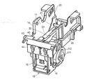
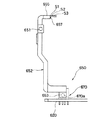
図1において、1は例えば複写機等に取り付けられる電動ステープラーであり、この電動ステープラー1は、ステープラー本体10と、ステープラー本体10内に形成したカートリッジ室11に着脱可能に装着されるカートリッジ700(図33参照)とから構成されている。
【0009】
ステープラー本体10には、上下に往復動するテーブル100と、テーブル100を往復動させるテーブル機構200(図13参照)と、カートリッジ700に設けた打出部50からステープルSaを打ち出していく打出し機構300(図23参照)と、打ち出されたステープルの先端部を折り曲げるクリンチャ機構400(図20参照)と、各機構200,300,400を駆動する駆動機構500(図7参照)と、テーブル100のホーム位置を検知する位置検知機構600(図24参照)と、打出部50にステープルSaがあるか否かを検知する針検知機構650(図25参照)とが設けられている。
【0010】
カートリッジ700には、カートリッジ700内に積層されたシートステープルSTを打出部50へ送り出す送り機構900(図34参照)が設けられている。
【0011】
ステープラー本体10は、図2および図3に示すように、金属製のフレーム12と、このフレーム12の内側に取り付けられたサブフレーム13と、このサブフレーム13に取り付けられた樹脂製のマガジン14とを備えている。
【0012】
サブフレーム13の両側板部15,16には、図4に示すように、上下方向に延びた長孔17,17と、駆動軸用の孔18と、軸孔19等とが設けられている。軸孔19には軸253が貫装されている。
【0013】
マガジン14はカートリッジ室11を形成しており、マガジン14の両側壁20の内側にはカートリッジ700を案内する傾斜ガイド部21がそれぞれ形成されている。また、マガジン14の底部22にはカートリッジ700の送り機構900が入る凹部23が形成されている。
【0014】
また、マガジン14の前壁部44の上部には、綴りシートを挟み込むための平坦状の載置部45が形成されており、この載置部45の内側には凹部46が形成されている。この凹部46には後述するカートリッジ700のフェイスプレートが入り込むようになっている。また、前壁部44と底部22との間には後述するドライバ350およびフェイスプレート351が進入する穴(図示せず)が形成されている。
【0015】
フレーム12の側板部24,25には、前側の下部に傾斜した一対のガイド孔26が形成され、後部の上部には一対の軸27が設けられている。また、側板部24,25間には駆動軸510が回転自在に貫装されている。側板部24にはギアスタッド28が設けられている。
【0016】
また、側板部24には、モータ用の軸孔30と、この軸孔30の近傍位置にネジ孔31と、軸孔30の近傍位置に図5に示すように内側に突出したダボ32,32とが形成されている。側板部24のネジ孔31には図6に示すようにネジN1が通されて駆動モータ40のフレームの前端面40Aに螺合し、駆動モータ40が側板部24に取り付けられている。
【0017】
ダボ32,32は駆動モータ40のフレームの前端面40Aに当接しており、駆動モータ40はネジN1,N1とダボ32,32とにより4点で支持されている。しかも、その4点は駆動モータ40の出力軸41に近い位置にあるため、側板部24の面のうねりの影響を極力避けることができ、駆動モータ40の出力軸41をうねりのない側板部24に対して垂直に保つことができる。この結果、駆動モータ40の出力を後述する中間ギア502に出力ダウンすることなく伝達することができる。
[駆動機構500]
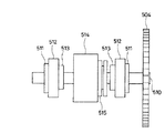
駆動機構500は、図7に示すように、フレーム12の側板部24に取り付けられたモータ40と、このモータ40の駆動軸41に取り付けられたギア501と、ギア501に噛合した中間ギア502,503と、中間ギア503に噛合した駆動ギア504と、この駆動ギア504とともに回転する駆動軸510等とから構成されている。中間ギア502,503はギアスタッド28に回転自在に取り付けられている。
【0018】
駆動軸510は、モータ40の駆動により各ギア501〜504を介して時計方向(図7において)に回動していく。
【0019】
駆動軸510には、図8に示すように、一対のクリンチャカム511,511と、一対のテーブルリンクカム512,512と、テーブルリンクカム512,512に一体的に形成された一対のテーブルリターンカム513,513と、ドライバカム514と、テーブル100のホームポジションを検知するためのポジションカム515とが取り付けられている。
【0020】
駆動軸510はサブフレーム13の両側板部15,16の孔18に回転自在に貫装されており、サブフレーム13内にはドライバカム514とポジションカム515とが配置され、サブフレーム13とフレーム12との間にはクリンチャカム511,511とテーブルリンクカム512,512とテーブルリターンカム513,513とが配置されている。
[テーブル100]
テーブル100は、図9に示すように、平板状のテーブル部101の両端に後方へ延びたアーム部102,102を形成したものである。テーブル部101には、左右方向に延びた開口103が形成されている。各アーム部102は図10および図11に示す第2テーブルリンク210の側板部211,211に取り付けられている。
【0021】
第2テーブルリンク210の前端板212には、図12に示す一対のクリンチャホルダ113,114が相対向してネジN2により取り付けらており、このクリンチャホルダ113,114間であって且つテーブル100の開口103の上方位置にクリンチャ115,116が配設されている。クリンチャホルダ113,114には突起軸117,118が設けられ、この突起軸117,118がクリンチャ115,116の小孔119,120に挿入されていて、クリンチャ115,116が突起軸117,118を中心にして回動自在となっている。
[テーブル機構200]
テーブル機構200は、図13ないし図15に示すように、駆動軸510に設けた一対のテーブルリンクカム512と、一対の第1テーブルリンク201と、第2テーブルリンク210と、一対のテーブルリターンカム513と、一対のテーブルリターンレバー250等とから構成されている。
【0022】
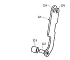
第1テーブルリンク201は、図16に示すように、上下方向に延びるとともにその下部に軸202を設けている。この軸202にはテーブルリンクカム512の周面に当接したローラ203が回転自在に装着されている。また、軸202にはネジN3(図13参照)が取り付けられており、このネジN3の頭Naがフレーム12のガイド孔26に挿入されている(図2参照)。第1テーブルリンク201はそのガイド孔26に沿って上下動可能となっている。第1テーブルリンク201の上部には孔204と係止部205とが形成されており、孔204には軸206(図15参照)が取り付けられている。
【0023】
第2テーブルリンク210は、前端板212の両端から後方に延びた側板部211,211と、この側板部211,211の外側に所定距離離間した位置に形成したアーム板部213,213とを有している(図10参照)。側板部211,211とアーム板部213,213とはその上部が連結部214,214により連結されている。
【0024】
側板部211およびアーム板部213には、後方に行くにしたがって上がっていく紙厚調整用の長孔215A,215Bが相対向して形成され、その長孔215A,215Bの後方に軸孔216が形成されている。また、アーム板部213の後部には係止部217が形成されている。
【0025】
第2テーブルリンク210の側板部211とアーム板部213との間に第1テーブルリンク201の上部が入っており、第1テーブルリンク201の軸206が側板部211およびアーム板部213の長孔215A,215B間に貫装されている。また、第2テーブルリンク210のアーム板部213の軸孔216にはフレーム12に設けた軸27が挿入されており、第2テーブルリンク210が軸27を中心にして回動可能となっている。第2テーブルリンク210の係止部217と第1テーブルリンク201の係止部205との間には紙厚調整バネ220が取り付けられており、この紙厚調整バネ220により第1テーブルリンク201の軸206が図15に示す矢印方向に付勢されている。
【0026】
第1テーブルリンク201は、テーブルリンクカム512の周面にローラ203が当接していることにより、テーブルリンクカム512が回動すると、この回動とともにフレーム12のガイド孔26に沿って図15に示す位置から下方に移動していく。第1テーブルリンク201の下方への移動により第2テーブルリンク210は、図17に示すように、フレーム12の軸27を中心にして反時計回りに回動していく。
【0027】
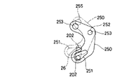
テーブルリターンレバー250は、図18に示すように、ほぼC字形に形成され、その下部に長孔251と、中間部の上には軸孔252とがそれぞれ形成されており、その上部にはローラ255が設けられている。このローラ255はテーブルリターンカム513の周面に当接しており、軸孔252にはサブフレーム13に設けた軸253の端部が挿入されている。また、長孔251には第1テーブルリンク201の軸202が挿入されている。
【0028】
テーブルリターンレバー250は、テーブルリターンカム513が回動すると、図19に示すように、軸253を中心にして実線の位置と鎖線の位置との間を回動するようになっている。そして、図17に示すように、第1テーブルリンク201が下方へ移動した際にテーブルリターンレバー250は図19に示す実線位置に移動し、図15に示すように第1テーブルリンク201が上方位置(初期位置)に移動している際にテーブルリターンレバー250は図19に示す鎖線位置に移動するようになっている。
【0029】
テーブルリターンレバー250が図19に示す実線位置から鎖線位置へ移動すると、テーブルリターンレバー250の長孔251に第1テーブルリンク201の軸202が挿入されており、しかもこの軸202に取り付けたネジN3の頭Naがフレーム12のガイド孔26に挿入されていることにより、軸202はガイド孔26にガイドされて上方に移動する。この移動とともに第1テーブルリンク201は図17に示す位置から図15に示す位置(初期位置)へ移動する。この移動により、第2テーブルリンク210は図17に示す位置から時計方向へ回動して図15に示す位置へ移動する。この移動により、第2テーブルリンク210はテーブル100を図1に示す待機位置(ホームポジション)へ戻す。
【0030】
テーブルリターンレバー250とテーブルリターンカム513等とによって、テーブル100を元の位置(待機位置)へ戻すテーブルリターン機構が構成されている。このテーブルリターン機構により、テーブルリンクカム512の周面にローラ203を常に当接させておくスプリングを設ける必要がない。このため、テーブル100を下方へ移動させるとき、そのスプリングの付勢力に抗してテーブルリンクカム512を回動させずに済むので、モータ40の出力は小さなものでよいことになる。
[クリンチャ機構400]
クリンチャ機構400は、図20に示すように、駆動軸510に設けた一対のクリンチャカム511と、一対の第1クリンチャリンク401と、一対の第2クリンチャリンク410と、クリンチャ115,116等とから構成されている。
【0031】
第1クリンチャリンク401の下部は、フレーム12にスタッド402を介して取り付けた軸403に回動可能に取り付けられている。この第1クリンチャリンク401の側部にはクリンチャカム511の周面に当接する当接部405が形成され、その上部には後方(図20において右方)へ延びるとともに第2クリンチャリンク410のローラ411に当接する当接部406とが形成されている。この第1クリンチャリンク401は、クリンチャカム511により軸403を中心にして反時計方向へ回動していく。
【0032】
第2クリンチャリンク410はほぼC字状に形成され、その上部が第2テーブルリンク210の側板部211に設けた軸412に回動自在に取り付けられている。第2クリンチャリンク410の上部の先端には前方(図20において左方)に突出した突起413が形成され、この突起413がクリンチャ116の凹部116Aに係合している。同様に、他の第2クリンチャリンク410の突起413がクリンチャ115の凹部115Aに係合している。第2クリンチャリンク410の下部にはローラ411が設けられている。
【0033】
第2クリンチャリンク410は、第1クリンチャリンク401の反時計方向への回動により、軸412を中心にして時計方向(図20において)へ回動していく。第2クリンチャリンク410,410の回動により、各クリンチャ115,116はクリンチャホルダ113,114の突起軸117,118を中心にして、図21(A)に示す位置から矢印方向へ回動して図21(B)に示す位置へ移動する。このクリンチャ115,116の回動によってステープルの先端部がクリンチされることになる。
【0034】
クリンチャ115,116は、図示しないバネにより図21(A)に示す矢印方向とは逆方向に付勢されており、クリンチ終了後にはそのバネの付勢力により図21(B)に示す位置から図21(A)に示す位置へ戻る。また、この戻りにより、第2クリンチャリンク410は図20に示す位置へ戻ることになる。
[打出し機構300]
打出し機構300は、図22および図23に示すように、駆動軸510に取り付けられたドライバカム514と、サブフレーム13の軸253に回動自在に取り付けられた一対のドライバリンク301と、このドライバリンク301に取り付けられたドライバ350およびフォーミングプレート351等とから構成されている。
【0035】
ドライバリンク301,301間にはドライバカム514の周面に当接したローラ302が回動自在に設けられている。ドライバリンク301は、ドライバカム514の回転とともに軸253を中心にして回動して、ドライバ350およびフォーミングプレート351をサブフレーム13の長孔17に沿って上下動させる。すなわち、ドライバカム514の1回転によりドライバ350およびフォーミングプレート351は上下に1往復するようになっている。
[位置検知機構600]
位置検知機構600は、図24ないし図26に示すように、駆動軸510に設けられたポジションカム515と、検知アーム601と、この検知アーム601の遮光板602を検知するホトセンサ610等とから構成されている。
【0036】
ポジションカム515には、図27および図28に示すように、ホームポジションを示す凹部604と、この凹部604の対称位置に突部605と、これら凹部604および突部605を縦断した環状溝606とが形成されている。そして、凹部604の深さと突部605の高さとが同一に設定され、環状溝606の深さは凹部604よりも深くなっている。
【0037】
検知アーム610は、サブフレーム13の軸253に回動自在に取り付けられており、ポジションカム515の上方位置まで延びた円弧状の第1アーム部611と、この第1アーム部611の下部からポジションカム515の下方を通って前方(図26において左方)へ延びた第2アーム部612とを有している。第1アーム部611の先端にはポジションカム515の周面に摺接していく突出部613が形成され、この突出部613にはポジションカム515の環状溝606に入り込んだガイド突起614が設けられている。図29に示すように、ガイド突起614の高さHはポジションカム515の凹部604の深さDよりも大きく設定されている。このガイド突起614により、第1アーム部611の突出部613がずれることなくポジションカム515の周面を摺接していくことになる。
【0038】
第2アーム部612にはポジションカム515の周面に摺接していく突出部616が形成されている。この突出部616は、駆動軸510の回転中心に対して第1アーム部612の突出部613と対称となる位置にある。また、第2アーム部612の先端には遮光板602が設けられている。
【0039】
第1アーム部611の突出部613がポジションカム515の凹部604に入ると、第2アーム部612の突出部616がポジションカム515の突部605に乗り上げるようになっている。すなわち、第1アーム部611の突出部613と第2アーム部612の突出部616とで常にポジションカム515を挟持するようになっている。
【0040】
ホトセンサ610は、サブフレーム13に取り付けた基板620に設けられており、発光ダイオード610aと、この発光ダイオード610aが発光する光を受光する受光ダイオード610b等とから構成され、遮光板602が発光ダイオード610aの光を遮光することにより、遮光板602を検知するものである。
【0041】
そして、図26に示すように、第1アーム部611の突出部613がポジションカム515の凹部604に入り込んだとき、すなわち、第2アーム部612の突出部616がポジションカム515の突部605に乗り上げたとき、検知アーム610の遮光板602が発光ダイオード610aの光を遮光するようになっている。これは、テーブル100が図1に示すホームポジションに位置したときである。すなわち、テーブル100が図1に示すホームポジションに位置したとき、検知アーム610の遮光板602が発光ダイオード610aの光を遮光するようにするように設定されている。
[針検知機構650]
針検知機構650は、図30に示すように、サブフレーム13のマガジン14(図1参照)に軸651を中心にして回動可能に設けられたアクチュエータ652と、アクチュエータ652の下部に設けた遮光板653を検知するホトセンサ670等とから構成されている。
【0042】
アクチュエータ652の上端部にはステープルSに接触する接触部655が設けられており、この接触部655には図31に示すように平面状の接触面656が形成され、この接触面656の上部がステープルSに接触するようになっている。この接触面656の下部側には突出部657が形成されている。
【0043】
ホトセンサ670は、発光ダイオード670aと、この発光ダイオード670aが発光する光を受光する受光ダイオード670b等(図25参照)とから構成され、遮光板653が発光ダイオード670aの光を遮光することにより、遮光板653を検知するものである。
【0044】
アクチュエータ652は、後述するカートリッジ700の打出部50の間隙765にステープルS1があるとき、その接触面656がステープルS1に接触して図30に示す位置に位置する。このときには、アクチュエータ652の遮光板653が発光ダイオード670aの光を遮光し、受光ダイオード670bは受光しない。これにより、その間隙765にステープルS1があると制御装置(図示せず)が判断する。
【0045】
その間隙765にステープルS1がないときには、図32に示すように、アクチュエータ652は軸651を中心にして回動し、この回動によりアクチュエータ652の遮光板653が発光ダイオード670aと受光ダイオード670bとの間から外れ、受光ダイオード670bが発光ダイオード670aの光を受光する。この受光により、間隙765にステープルS1がないと制御装置(図示せず)が判断する。
【0046】
また、アクチュエータ652の接触面656に突出部657を設けたので、ドライバ350が上昇してステープルS1を打ち出す際に、ドライバ350が突出部657に接触して接触面656に接触しないことになる。すなわち、ドライバ350が突出部657に接触すると、アクチュエータ652が軸651を中心にして反時計方向(図30において)に回動するので、ドライバ350は接触面656に接触しないことになる。このため、ドライバ350による接触面650の磨耗が防止され、間隙765にステープルS1があってもそのステープルS1を検知しなくなってしまうという誤動作の発生が防止される。また、接触面650の磨耗の防止によりアクチュエータ652の耐久性が向上することになる。
[カートリッジ700]
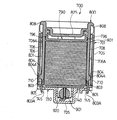
カートリッジ700は、図33ないし図39に示すように、外ケース701と、この外ケース内に上下動可能に設けられた内ケース800と、内ケース800内に上下動可能に設けられたホルダー790等とから構成されている。
[外ケース701]
外ケース701は、図36に示すように後部(右側)と上部とに開口702,703を形成し、前壁部704の下部に前方へ突出した保持部705を設けている。また、外ケース701は一対の側壁706を有し、側壁706の内側面には上下方向に延びたガイド凹部707,708が形成され、側壁706の外側面の下部には、突起709と、ガイド凹部708に対応した位置に凹部710が形成されている。また、前壁部704にはその下端から上方に延びた窓713が形成されている。
【0047】
保持部705の下面にはガイド板720が取り付けられており、また、保持部705には前後方向に移動可能なプッシャ部材750が設けられており、側壁706,706の下部にはガイドホルダ730が取り付けられている。また、保持部705の前面には孔711が設けられている。
【0048】
ガイドホルダ730には、ガイド板740と送り機構900とが設けられている。ガイドホルダ730の前後には上方へ突出したそれぞれ一対の支持板部731,732が設けられており、支持板部731には係合孔733が形成され、支持板部732の内側には係止突起734が設けられている。支持板部731,731の係合孔733,733には外ケース701の側壁706,706の突起709,709が係合され、支持板部732,732の係止突起734,734は側壁706,706の内側面に設けた凹部(図示せず)に係合されていることにより、ガイドホルダ730が外ケース701に取り付けられている。また、ガイドホルダ730には、送り機構900を設けるための収納部735と、収納部735の前後に係止部736,737とが形成されている。
【0049】
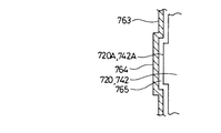
ガイド板740には、後述するシートステープルSTを積層したケース850の底壁部851を受けるホルダ部741と、このホルダ部741の面より一段高くなっているガイド部742とが形成されている。ホルダ部741とガイド部742との段差の高さはケース850の底壁部851の厚さと同じに設定されている。そして、ガイド部742と保持部705のガイド板720とでステープルSを前方へ送る搬送路721が形成され、各ガイド板720,740の先端には突出部720A,740Aが形成されている。
【0050】
このように、外ケース701のガイドホルダ730に設けたガイド板740のガイド部742と、外ケース701の保持部705に取り付けたガイド板720とで搬送路721を形成したものであるから、ホッチキス本体10の構成に拘わらず搬送路721の隙間(高さ)の寸法精度が決定される。このため、その寸法精度の集積公差を小さくすることができ、カートリッジ700側のみでステープルS送りの性能を管理することができる。
【0051】
また、ガイド板740には、ホルダ部741の前側からガイド部742の後端に亘って前後方向に延びた一対のスリット743,743が形成され、ホルダ部741に一対の孔745が形成されている。
【0052】
プッシャ部材750は、前面に傾斜面751を有するとともに後方に突出して保持部705の孔711に挿入された突出部752と、図40に示すように、この突出部752の両側に形成された当接面753とを有している。このプッシャ部材750は図示しないスプリングにより前方に付勢されている。
【0053】
また、外ケース701の側壁706,706にはフェイスプレート部材760のアーム部761,761が枢支され、軸762を中心に矢印方向へ図34に示すように回動可能となっている。フェイスプレート部材760は平板状のフェイスプレート部763を備えており、このフェイスプレート部763には、図41に示すように、前方に突出したフェイス部764が形成されている。このフェイス部764と各ガイド板720,740の突出部720A,740Aとの間にドライバ350が進入してくる間隙765が形成されている。そして、フェイス部763の上部と保持部705の上部との間(打出口)51からステープルSがマガジン14の載置部45(図1参照)に載置された綴りシート(図示せず)に向けて打ち出されていくものであり、フェイス部763と保持部705とで打出部50が構成されている。
【0054】
また、突起804から下の弾性脚部803の部分の内側面803Aは、図39に示すように、側壁801の内側面より外側に位置しており、内側面803A,803A間の距離が側壁801,801の内側面間の距離より大きくなっている。
【0055】
内ケース800の両側壁801は外ケース701の側壁706の内側に当接しており、内ケース800は外ケース700に対して上下方向に摺動移動するようになっている。内ケース800が外ケース701内に完全に挿入されると、図39に示すように、内ケース800の弾性脚部803がガイドホルダ730に設けたガイド板740の孔745に挿入され、弾性脚部803の係止爪805がその孔745に係止するようになっている。また、このとき、弾性脚部803の突起804は、外ケース701の側壁706の凹部710の位置に位置するようになっている。
【0056】
また、両側壁801の前側には上下方向に延びた長孔807が形成され、両側壁801の上部には上方に突出した把手部808が形成されている。
【0057】
内ケース800の後壁810の下端には係止突起811が形成され、天板820の前端には側板801の前端から所定距離離間するとともに下方に延びたV字形の支持板部821が形成され、この支持板部821の下部には後方に突出した突起823が形成されている。この突起823は外ケース701の前壁部704の窓713の下部(図35参照)に入り込んでいる。また、天板820には下方に突出したバネ取付部825が形成されている。
[ホルダ790]
ホルダ790は、四角形状に形成された枠体791と、この枠体791の下部に形成された底板792とを有し、この底板792の中央部に筒壁部793が形成されている。また、枠体791の両側壁部794には、内ケース800の側壁801の長孔807に挿入された突起795と、内ケース800の側壁801に当接した突出部796とが形成されている。ホルダ790は、突起795が側壁801の長孔807に案内されるとともにその突出部796が内ケース800の側壁801に摺接して上下動するようになっている。
【0058】
また、枠体791の前壁部797には係止突起798が形成され、この係止突起798は内ケース800の前面開口800Aから外ケース701の前壁部704の窓713に挿入されている。
【0059】
枠体791の筒壁部793の内側には、図42に示すように、スプリング780の下部が取り付けられており、スプリング780の上部が内ケース800の天板820のバネ取付部825に嵌合している。このスプリング780の付勢力によりホルダ790は下方に付勢されて、内ケース800内に収納されたシートステープルSTを下方に押圧している(図39参照)。
【0060】
積層されたシートステープルSTは、紙製のケース850によって保持されており、ケース850は、前面と上面が開口されているとともに底壁部851と側壁部852と後壁部853とを有している。
[送り機構900]
送り機構900は、図43ないし図46に示すように、前後方向に延びたラチエットプレート901と、送爪910と、バネガイド920と、送りバネ930等とから構成されている。
[ラチエットプレート901]
ラチエットプレート901は、図47および図48に示すように、先端部に前方に行くにしたがって上がっていく傾斜面902と、幅広の中間部903に形成された円形状の孔904と、その中間部903の上端から孔904まで延びた切欠905と、中間部903から後方へ延びた幅の小さいロッド部906とを有している。また、中間部903の後側の下部には側方に突出した受部907が形成されている。
[送爪910]
送爪910は、図49に示すように、先端が尖っている一対の爪部911を備え、爪部911の間には幅広の切欠912と、さらにこの切欠912の中間位置に幅の狭い切欠913が形成されている。そして、切欠913の両側が脚部914,914とされている。また、送爪910の後端に切欠915が形成され、切欠915と切欠913との間が連結部916とされている。この連結部916がラチエットプレート901の孔904に挿入され、送爪910の脚部914,914がラチエットプレート901の孔904から中間部903の上端までを跨って、送爪910がラチエットプレート901に装着されている。
[バネガイド920]
バネガイド920は、図50に示すように、円柱体921に傾斜面922を形成し、その傾斜面922から後部に延びた切欠923を設け、さらに円柱体921の後部に切欠923に連通した孔924を設けたものである。
【0061】
そして、図45に示すように、バネガイド920の孔924にはラチエットプレート901のロッド部906が貫装され、バネガイド920の切欠923にラチエットプレート901の中間部903が入り込んでラチエットプレート901に装着された送爪910がバネガイド920の傾斜面922に当接している。また、ロッド906には送りバネ930が取り付けられている。
【0062】
このバネガイド920は、図35および図39に示すように、ガイドホルダ730の収納部735に収納されているとともにラチエットプレート901の受部907が収納部735の底面735Aに当接している。この受部907によって、ラチエットプレート901およびバネガイド920が前後方向に移動可能に支持されている。また、送りバネ930の一端はガイドホルダ703の係止部737に係止されている。この送りバネ930によりラチエットプレート901およびバネガイド920は前方に付勢されている。ラチエットプレート901の中間部903がガイドホルダ730の係止部736に当接して、ラチエットプレート901およびバネガイド920は図35に示す位置より前方に移動しないように規制されている。
【0063】
送爪910の爪部911は、ガイド板740のスリット743に挿入されていて、ホルダ部741の上面より上に突出するようになっている。
[送り機構900の動作]
積層されたシートステープルSTがガイド板740のホルダ部741に載置されると、図51に示すようにその重みにより送爪910は倒れ込んでガイド板740のスリット743から送爪910の爪部911が引き込む状態となる。送爪910の倒れ込み(沈み込み)は、送爪910がラチエットプレート901の孔904を中心にして反時計方向(図51において)へ回動することにより行われる。この回動の際に、バネガイド920は送りバネ930の付勢力に抗して後方(図51において右方)へ少し移動することになる。
【0064】
そして、ドライバ350およびフォーミングプレート351が上昇していくと、ドライバ350がラチエットプレート901の傾斜面902に当接する。さらに、上昇していくと、その上昇にともなって傾斜面902によりラチエットプレート901およびバネガイド920が図51に示す状態のまま送りバネ930の付勢力に抗して図52に示す位置まで後方へ移動する。
【0065】
ドライバ350によるステープルSの打ち込みが完了して、ドライバ350およびフォーミングプレート351が初期位置へ下降すると、送りバネ930の付勢力によりバネガイド920が送爪910を前方へ押していく。このとき、バネガイド920の傾斜面922により送爪910は図45に示すように起き上がる。そして、送りバネ930の付勢力によりバネガイド920とともにラチエットプレート901が前方へ移動していくと、起き上がった送爪910の爪部911はガイド板740のスリット743から上方へ突出して、シートステープルSTのステープルSとステープルSの間に爪部911の先端部が入り込んでいく。このため、ラチエットプレート901の移動とともに送爪911はシートステープルSTを前方へ送り出していく。
【0066】
上述のように、送りバネ930の付勢力によってバネガイド920が送爪910を押圧していくと、バネガイド920の傾斜面922により送爪910は図45に示すように起き上がり、また、送りバネ930の付勢力によってシートステープルSTが送られていく。このように、1つの送りバネ930によってシートステープルSTの送りと送爪910の起き上がりを行っているので、送爪910を起き上がらせるバネは不要となり、部品点数を削減することができることになる。
【0067】
搬送路721にシートステープルSTがない場合、図45および図51に示す位置までラチエットプレート901が移動し、シートステープルSTの送り出し量が大きくなるようになっている。搬送路721にシートステープルSTがある場合には、図52の位置から前方へ一個のステープルSの幅W(図31参照)だけ移動することになる。
[電動ステープラーの動作]
次に、上記のように構成される電動ステープラー1の動作について説明する。
【0068】
先ず、ケース850に積層されたシートステープルSTを収納したカートリッジ700をホッチキス本体10に予め装着しておく。モータ40が駆動していないときには、テーブル100は図1に示す初期位置(ホームポジション)に位置している。
【0069】
図示しない複写機からの綴り信号によってモータ40が駆動されると、ギア501〜ギア504を介して駆動軸510が時計方向(図7において)に回転していき、駆動軸510とともに各カム511〜515も回転していく。
【0070】
テーブルリンクカム512の回転により、図17に示すように、第1テーブルリンク201が下方へ移動していき、この移動により第2テーブルリンク210は、フレーム12の軸27を中心にして反時計回りに回動していく。テーブル100は、第2テーブルリンク210とともに回動して下降していくことになる。テーブル100が図17に示す位置(下死点)まで下降すると、マガジン14の載置部45とテーブル100との間にある綴りシート(図示せず)をその載置部45とテーブル100とで挟持する。
【0071】
この挟持の際、テーブル100はマガジン14の載置部45に衝突する状態となるが、テーブル100は第2テーブルリンク210の軸27を中心にして回動しながら載置部45に衝突することになる。すなわち、一端が軸27に支えられて他端側が衝突していくので、何も支えられずに衝突していく場合に比較して、その衝突時の衝撃は小さくなる。このため、衝撃が小さいことによりステープルSの送り出しが安定するとともに衝突時の騒音も小さくなる。
【0072】
また、テーブル100は第2テーブルリンク210の軸27を中心にして回動するようにしたものであるから、軸27と第2テーブルリンク210の軸孔216との関係のみでガイド性(安定した動作)が決定され、その軸27と軸孔216との関係の構造も簡単である。さらに、ステープルSの送り出しの安定化と安定した動作により信頼性が向上することになる。
【0073】
一方、ドライバカム514の回転によってドライバリンク301がドライバ350およびフォーミングプレート351を上昇させていき、綴りシートの挟持後には、ドライバ350およびフォーミングプレート351がマガジン14の穴(図示せず)を通ってカートリッジ700の打出部50の間隙765に進入していき、フォーミングプレート351がステープルS3(図31参照)を図54に示すようにコ字状に成形し、ドライバ350がコ字状に成形されているステープルS1を打出部50の打出口51から綴りシートへ打ち出していく。
【0074】
この打出の際、ステープルS1は傾斜面751を跨ってこの傾斜面751に沿って打ち出されていくので、ドライバ350の上昇にともなってプッシャ部材750はスプリングの付勢力に抗して後退していく。このとき、図55に示すようにステープルS1の脚部Saが突出部752の側面752Aに当接していくので、その脚部Saの座屈が防止される。
【0075】
打出が終了してドライバ350が下降すると、この下降にともなってプッシャ部材750はスプリングの付勢力によって前進してくる。この前進により、コ字状に成形されたステープルS3の脚部Sbがプッシャ部材750の当接面753によって前方へ押される。この結果、ステープルSが前方へ送り出されることになる。
【0076】
ドライバ350によるステープルの打出の際、図17に示す矢印方向からテーブル100に力Fが加わることになる。この力Fにより第2テーブルリンク210は軸27を中心に時計方向へ回動しようとするが、第1テーブルリンク201のローラ203はドライバカム514によって押さえられている状態となっているので、第1テーブルリンク201は上方に移動することはできない。この結果第1テーブルリンク201はローラ203を中心にして反時計方向へ回動して、第2テーブルリンク210の時計方向への回動を許容させようとするが、紙厚調整バネ220の付勢力により第1テーブルリンク201の反時計方向への回動は阻止される。
【0077】
すなわち、ドライバ350の打出による力Fがテーブル100に加わってもスプリング220の付勢力によりテーブル100は移動しないことになる。
【0078】
また、テーブル100に力Fが加わった際、図53に示すように、このテーブル100を支えるために軸206にはF1の力が必要であるとすると、F1の分力FXは紙厚調整バネ220が支え、F1の分力FYは駆動軸510等が支えることになる。すなわち、F1をFXとFYに分散させて、FXのみを紙厚調整バネ220で支えるようにしたものであるから、紙厚調整バネ220の付勢力は小さくて済むことになる。
【0079】
なお、長孔215Aの傾斜方向を逆にして、テーブル100に力Fが加わった際に、第1テーブルリンク201を時計方向へ回動するようにした場合には、紙厚調整バネ220は圧縮バネとなる。
【0080】
綴りシートが厚い場合には、テーブル100は下死点まで下降せずに、例えば図56に示す位置に停止することになる。しかし、テーブルリンクカム512の回動により、図57に示すように、第1テーブルリンク201の軸206が第2テーブルリンク210の長孔215A,215Bに、第1テーブルリンク201の軸202がフレーム12のガイド孔26に案内されながら第1テーブルリンク201が下降していく。この第1テーブルリンク201の下降により、テーブルリンクカム512は綴りシートの厚さに拘わらずロックされずに回転していく。
【0081】
また、第1テーブルリンク201は紙厚調整バネ220の付勢力に抗して第2テーブルリンク210の長孔215A,215Bに沿って下降することになるが、紙厚調整バネ220の付勢力が小さくて済むことにより、テーブルリンクカム512は回動力が小さくてもロックされないことになる。
【0082】
ドライバ350およびフォーミングプレート351が上昇してマガジン14の穴を通ってカートリッジ700の打出部50の間隙765へ進入すると、図52に示すように、送り機構900のラチエットプレート901および送爪910等が後方へ移動する。
【0083】
他方、クリンチャカム511の回転により、ステープルS1の打出終了後、第1クリンチャリンク401が反時計方向(図20において)へ回動し、この回動により第2クリンチャリンク410が時計方向へ回動していく。図21に示すように、第2クリンチャリンク410,410の回動により、各クリンチャ115,116が突起軸117,118を中心にして回動する。この回動により、綴りシートを貫通したステープルS1の脚部の先端部を各クリンチャ115,116がクリンチする。
【0084】
このクリンチが終了すると、フォーミングプレート351およびドライバ350が下降していくとともに、第1,第2クリンチャリンク401,410およびクリンチャ115,116が元の位置へ戻る。
【0085】
フォーミングプレート351およびドライバ350が元の位置へ戻ると、送りバネ930の付勢力によりバネガイド920とともにラチエットプレート901および送爪911が前方へ移動していき、シートステープルSTをステープルSの幅W(図31参照)だけ前方へ送り出していく。
【0086】
また、クリンチ終了後には、テーブルリターンカム513の回転によりテーブルリターンレバー250がテーブル100を元の待機位置(ホームポジション)へ戻す。
【0087】
テーブル100が待機位置へ戻ると、駆動軸510とともにポジションカム515は1回転しており、図26に示すように、検知アーム601の第1アーム部611の突出部613がポジションカム515の凹部604に入り込むとともに、第2アーム部612の突出部616がポジションカム515の突部605に乗り上げている。この状態のとき、検知アーム601の遮光板602は発光ダイオード610aの光を遮光する。この遮光により、ポジションセンサ610の受光ダイオード610bがポジション検知信号を出力する。このポジション検知信号により制御回路はテーブル100がホームポジションに戻ったことを判断し、次の綴り動作を行う待機状態となる。
【0088】
ところで、検知アーム601にはポジションカム515の凹部604に対応して突出部616を設け、しかも、第1アーム部611の突出部613と第2アーム部612の突出部616とで常にポジションカム515を挟持するようにしたものであるから、第1アーム部611の突出部613を常にポジションカム515の周面に当接させておくためのバネは不要となり、省スペース化や部品点数の削減を図ることができることになる。また、第1アーム部611の突出部613と第2アーム部612の突出部616とでポジションカム515を挟持するものであるから、ポジションカム515が高速で回転しても、第1アーム部611の突出部613がポジションカム515の周面に常に当接している。このため、その周面から突出部613が離間してしまうことがなく、チャタリングが発生してしまうことがない。
【0089】
先ず、カートリッジ700をホッチキス本体10から取り外す。カートリッジ700の内ケース800内にシートステープルSTが一枚もない場合には、図58に示すように、ホルダ790がスプリング780の付勢力により内ケース800の底部へ移動している。この場合、ホルダ790の突出部796は内ケース800の突起804より下方に位置し、内ケース800の側壁801から外れた状態にある。
【0090】
次に、外ケース701の両側壁706の凹部710を矢印方向へ指によって押圧すると、内ケース800の突起804が外ケース701の側壁706に当接していることにより、内ケース800の弾性脚部803が内側へ弾性変形する。これによって、弾性脚部803の係止爪805がガイド板740の孔745から外れる。そして、内ケース800の把手部808をもって内ケース800を外ケース701に対して上方へスライド移動させる。
【0091】
内ケース800が外ケース701の最上部位置へスライド移動されると、図59に示すように内ケース800の係止突起811が外ケース701の把持部1780に係止され、内ケース800が外ケース701から抜けないようになっている。また、内ケース800のスライド移動の際に、図38に示すように、内ケース800の突起823がホルダ790の係止突起798に係止し、内ケース800とともにホルダ790も上方へ移動していく。
【0092】
このため、内ケース800を図59に示す位置までスライド移動させると、外ケース701の後部の開口702が完全に開放される。また、内ケース800は摩擦力により図59に示す位置に保持される。そして、開口702から積層されたシートステープルSTをケース850ごと外ケース701内に入れる。このとき、内ケース800は図59に示す位置に保持されているので、そのケース850の挿入は簡単に行える。
【0093】
このように、内ケース800を図59に示す位置までスライド移動させると、ホルダ790も上方へ移動していくことにより外ケース701の後部の開口702が完全に開放され、しかも、内ケース800は摩擦力により図59に示す位置に保持されるので、ケース850の交換は容易なものとなる。
【0094】
シートステープルSTを積層したケース850が外ケース701内に挿入されたら、内ケース800を上から押して図39に示す位置まで押し下げる。すると、内ケース800の弾性脚部803がガイド板740の孔745に挿入されて、弾性脚部803の係止爪805がその孔745に係止される。
【0095】
図39に示すように、積層されたシートステープルSTがカートリッジ700の内ケース800内に残っている場合、メンテナンス時にそのカートリッジ700をステープラー本体10から外して、誤って外ケース701の凹部710を押しても、シートステープルSTが内ケース800の両側壁801を押さえている状態となっていることにより弾性脚部803は内側へ弾性変形することができない。このため、弾性脚部803の係止爪805がガイド板740の孔745から外れない。このため、外ケース701の凹部710を押してもスプリング780の付勢力によって内ケース800が上方へスライド移動してしまうことがなく、その開口702から積層されたシートステープルSTがばらまかれてしまうことが防止される。
【0096】
また、搬送路721の途中まで送られてシートステープルSTの一部が内ケース800内に残っている場合、ガイド板740のガイド部742がホルダ部741より高い位置にあることにより、ホルダ790は図61に示す位置に下降し、ホルダ790の突出部796は内ケース800の側壁801に当接するようになっている。このため、外ケース701の凹部710を押しても、ホルダ790の突出部796が内ケース800の側壁801に当接していることにより、内ケース800の弾性脚部803は内側へ弾性変形しない。
【0097】
したがって、弾性脚部803の係止爪804がガイド板740の孔745から外れず、内ケース800を上方へスライド移動させることができない。このため、外ケース701の後部の開口702からシートステープルSTを積層したケース850を挿入することができないことになる。
【0098】
これは、搬送途中のシートステープルSTの一部が内ケース800内に残っていても、内ケース800を上方へスライド移動させることができると、シートステープルSTの一部が内ケース800内に残っていることに気づかずに、外ケース701の後部の開口702からシートステープルSTを積層したケース850を挿入してしまう。すると、残っているシートステープルSTが積層されたシートステープルSTによって搬送路721内へ無理矢理に押し込まれてしまい、搬送路721内でシートステープルが重なったりして、ジャムが発生してしまうことになる。
【0099】
この実施形態によれば、シートステープルSTが内ケース800内に残っている場合、内ケース800を上方へスライド移動させることができないことにより、ジャムの発生の防止を図ることができる。
【0100】
また、カートリッジ700の外ケース701のガイドホルダ730に送り機構900を設けたものであるから、ステープルSの送りに関してカートリッジ700側のみの管理でその送り性能を保障することができ、生産性、信頼性を向上させることができる。ちなみに、ホッチキス本体10に送り機構900を設けると、カートリッジ700と本体10との間の位置関係が影響するため、カートリッジ700と本体10とには精密な寸法精度が要求される。
[第2実施形態]
図62は送り機構1000の第2実施形態を示したものである。この第2実施形態では、バネガイド920の傾斜面922に凹部940を設けたものである。この凹部940により、送爪910は沈み込む際にバネガイド920を送りバネ930の付勢力に抗して後方へ移動させるが、そのときのバネガイド920に働く送爪910からの作用点920Aの位置が図63に示すようにバネガイド920の軸線920Jに近くなる。他方、凹部940がない場合には、その作用点の位置は送爪910の下部910Aとなる。バネガイド920を後方に移動させる力は作用点が軸線920Jに近いほど小さい力で済むことになる。
【0101】
すなわち、作用点の位置が変わることにより、送爪910の沈み荷重が変わることになり、凹部940を設ける位置によって送爪910の沈み荷重を自由に調整することができることになる。また、送りバネ930のバネ荷重をアップした場合、作用点の位置を変えることにより送爪910の沈み荷重を変えずに済むことになる。
【0102】
【発明の効果】
以上説明したように、この発明によれば、ステープラー本体にマガジンと打出し機構と駆動機構とを設け、テーブルにクリンチャを設けたものであるからテーブルの重量は軽いものとなる。しかも、ステープラー本体に軸支するとともにこの軸を中心にテーブルを回動させることによりこのテーブルを上下動させるものであるから、テーブルが綴りシートを挟持する際に打出部に衝突する衝撃が小さくなる。この衝撃が小さいことによりステープルの送り出しが安定するとともに衝突時の騒音も小さくなる。
【0103】
また、テーブルの回動は軸と軸孔との関係のみでガイド性すなわち安定した動作が決定され、その軸と軸孔との関係の構造も簡単である。さらに、ステープルの送り出しの安定化と安定した動作により信頼性が向上する。
【図面の簡単な説明】
【図1】この発明に係わる電動ステープラーを示した斜視図である。
【図2】図1に示す電動ステープラーの一部を省略した斜視図である。
【図3】図1のサブフレームとマガジンを示した斜視図である。
【図4】図1に示すサブフレームを示した斜視図である。
【図5】モータの取り付け状態を示した説明図である。
【図6】ネジとボスとの位置関係を示した説明図である。
【図7】駆動機構の構成を示した説明図である。
【図8】駆動軸に取り付けられた各カムを示した説明図である。
【図9】テーブルを示した斜視図である。
【図10】第2テーブルリンクを示した斜視図である。
【図11】第2テーブルリンクにテーブルを取り付けた状態を示した説明図である。
【図12】クリンチャの組み付けを示す分解斜視図である。
【図13】テーブル機構の構成を示した斜視図である。
【図14】図13のテーブル機構を示した背面図である。
【図15】テーブル機構の構成を示した説明図である。
【図16】第1テーブルリンクを示した斜視図である。
【図17】第1テーブルリンクが回動した状態を示した説明図である。
【図18】テーブルリターンレバーとテーブルリターンカムを示した斜視図である。
【図19】テーブルリターンレバーの動きを示した説明図である。
【図20】クリンチャ機構の構成を示した説明図である。
【図21】(A)クリンチャを示した説明図である。
(B)クリンチャの回動状態を示した説明図である。
【図22】打出機構の構成を示した斜視図である。
【図23】打出機構を示した側断面図である。
【図24】位置検知検知機構と針検知機構の構成を示した斜視図である。
【図25】位置検知検知機構と針検知機構の構成を示した正面図である。
【図26】位置検知機構の構成を示した側面図である。
【図27】ポジションカムを示した縦断面図である。
【図28】ポジションカムを示した横断面図である。
【図29】第1検知アームの突出部とガイド突起を示した説明図である。
【図30】針検知機構の構成を示した説明図である。
【図31】針検知機構のアクチュエータの接触部とステープル等との関係を示した説明図である。
【図32】針検知機構のアクチュエータが回動した状態を示した説明図である。
【図33】カートリッジを示した斜視図である。
【図34】カートリッジを示した側面図である。
【図35】図34のカートリッジの断面図である。
【図36】カートリッジの構成を示した分解斜視図である。
【図37】カートリッジの構成を示した部分断面斜視図である。
【図38】カートリッジの構成を示した縦断面図である。
【図39】カートリッジの構成を示した横断面図である。
【図40】プッシャーとドライバーとの関係を示した斜視図である。
【図41】フェイスプレート部を示した説明図である。
【図42】ホルダが付勢されている状態を示した説明図である。
【図43】送り機構を示した斜視図である。
【図44】図43の正面図である。
【図45】送り機構の構成を示した側面図である。
【図46】送り機構の構成を示した底面図である。
【図47】送り機構の構成を示した分解斜視図である。
【図48】ラチエットプレートを示した側面図である。
【図49】(A)送爪を示した正面図である。
(B)送爪の側面図である。
【図50】(A)バネガイドを示した正面図である。
(B)バネガイドの底面図である。
(C)バネガイドの背面図である。
(D)バネガイドの側面図である。
【図51】送爪が沈み込んだ状態を示した説明図である。
【図52】ラチエットプレートおよび送爪等が後方へ移動した状態を示した説明図である。
【図53】軸に加わる力の分力を示した説明図である。
【図54】ステープルがコ字状に成形された状態を示した説明図である。
【図55】プッシャ部材の動作を示す説明図である。
【図56】綴りシートが厚い場合のテーブルの下降位置とテーブルリンクカム等との関係を示した説明図である。
【図57】綴りシートが厚い場合にテーブルリンクカムがロックしないことを示した説明図である。
【図58】内ケース内にシートステープルがない場合の内ケースとホルダ等との位置関係を示した断面図である。
【図59】シートステープルを積層したケースを外ケースの開口から挿入する状態を示した説明図である。
【図60】シートステープルを積層したケースを外ケース内に装填した状態を示した説明図である。
【図61】搬送路の途中まで送られたシートステープルの一部が内ケース内に残っている場合のホルダの下降位置を示した説明図である。
【図62】第2実施形態の送り機構を示した説明図である。
【図63】送爪に働く作用点を示した説明図である。
【符号の説明】
10 ステープラー本体
12 フレーム
24 側板部
25 側板部
27 軸
100 テーブル
350 ドライバ
S ステープル[0001]
BACKGROUND OF THE INVENTION
The present invention relates to an electric stapler provided with a table that is disposed so as to face a launching unit for ejecting staples and is provided on a stapler body so as to be movable up and down.
[0002]
[Prior art]
2. Description of the Related Art Conventionally, there is known an electric stapler that includes a table that is disposed so as to be opposed to a punching portion of a stapler body and that can be moved up and down, and a driver that drives a staple from the punching portion.
[0003]
In such an electric stapler, when the table is moved upward and the binding sheet is held by the punching unit, the driver descends and drives out staples from the punching unit. The leading end portion of the staple that has been punched out penetrates the spelling sheet, and this leading end portion is clinched by a clincher provided on the table.
[0004]
[Problems to be solved by the invention]
By the way, in such an electric stapler, the table is configured to move up and down in parallel, and therefore, the electric stapler collides with the launching portion while maintaining the initial posture. For this reason, there was a problem that the impact sound was loud.
[0005]
The present invention has been made in view of the above problems, and an object thereof is to provide an electric stapler capable of reducing impact noise.
[0006]
[Means for Solving the Problems]
In order to achieve the above object, the present invention is disposed so as to face the launching portion for launching staples.staplerA table provided on the main body so as to be movable up and down, and a driver that drives the staples from the punching portion toward the spelling sheet when the table moves and the spelling portion clamps the spelling sheet. electricstaplerBecause
The stapler body includes a magazine for detachably mounting a cartridge for storing sheet staples, a driving mechanism for driving the driver to drive the sheet staples, and a motor for driving the driving mechanism. Provided in
A clincher for clinching the staple punched out from the punching portion is provided on the table,
When the table is pivotally supported on the stapler bodyAlsoThe table is moved up and down by rotating around this axis.
[0007]
Hereinafter, the electric motor according to the present invention.staplerEmbodiments will be described with reference to the drawings.
[0008]
In FIG. 1, 1 is an electric motor attached to a copying machine, for example.staplerAnd this electricstapler1 isstaplerA
[0009]
staplerThe
[0010]
The
[0011]
staplerAs shown in FIGS. 2 and 3, the
[0012]
As shown in FIG. 4,
[0013]
The
[0014]
A
[0015]
The
[0016]
Further, the
[0017]
The
[Drive mechanism 500]
As shown in FIG. 7, the
[0018]
The
[0019]
As shown in FIG. 8, the
[0020]
The
[Table 100]
As shown in FIG. 9, the table 100 is formed by forming
[0021]
A pair of
[Table mechanism 200]
As shown in FIGS. 13 to 15, the
[0022]
As shown in FIG. 16, the
[0023]
The
[0024]
The
[0025]
The upper portion of the
[0026]
When the
[0027]
As shown in FIG. 18, the
[0028]
When the
[0029]
When the
[0030]
The
[Clincher mechanism 400]
As shown in FIG. 20, the
[0031]
A lower portion of the
[0032]
The
[0033]
The
[0034]
The
[Punching mechanism 300]
As shown in FIGS. 22 and 23, the
[0035]
A
[Position detection mechanism 600]
As shown in FIGS. 24 to 26, the
[0036]
As shown in FIGS. 27 and 28, the
[0037]
The
[0038]
The
[0039]
When the protruding
[0040]
The
[0041]
26, when the
[Needle detection mechanism 650]
As shown in FIG. 30, the
[0042]
A
[0043]
The
[0044]
When the staple S1 is in the
[0045]
When there is no staple S1 in the
[0046]
Further, since the protruding
[Cartridge 700]
33 to 39, the
[Outer case 701]
As shown in FIG. 36, the
[0047]
A
[0048]
The
[0049]
The
[0050]
In this way, the
[0051]
The
[0052]
The
[0053]
Further, the
[0054]
Further, as shown in FIG. 39, the
[0055]
Both
[0056]
A
[0057]
A locking
[Holder 790]
The
[0058]
Further, a locking
[0059]
As shown in FIG. 42, the lower part of the
[0060]
The stacked sheet staples ST are held by a
[Feeding mechanism 900]
As shown in FIGS. 43 to 46, the
[Ratchet plate 901]
47 and 48, the
[Nail feeding 910]
As shown in FIG. 49, the feeding
[Spring guide 920]
As shown in FIG. 50, the
[0061]
As shown in FIG. 45, a
[0062]
As shown in FIGS. 35 and 39, the
[0063]
The
[Operation of feeding mechanism 900]
When the stacked sheet staple ST is placed on the
[0064]
Then, as the
[0065]
When the driving of the staple S by the
[0066]
As described above, when the
[0067]
When there is no sheet staple ST in the
[electricstaplerOperation]
Next, the electric motor configured as abovestaplerThe operation of No. 1 will be described.
[0068]
First, the
[0069]
When the
[0070]
As the
[0071]
During this clamping, the table 100 collides with the
[0072]
Further, since the table 100 is configured to rotate around the
[0073]
On the other hand, the rotation of the
[0074]
At the time of launch, staple S1IsSince it is driven out along the
[0075]
When the driving is finished after the driving is finished, the
[0076]
When the staple is driven by the
[0077]
In other words, even if the force F generated by the
[0078]
Further, when a force F is applied to the table 100, as shown in FIG. 53, if a force of F1 is required for the
[0079]
When the
[0080]
When the spelling sheet is thick, the table 100 does not descend to the bottom dead center and stops at the position shown in FIG. 56, for example. However, due to the rotation of the
[0081]
Further, the
[0082]
When the
[0083]
On the other hand, the rotation of the
[0084]
When this clinching is finished, the forming plate351And drivers350, The first and second clincher links 401 and 410 and the
[0085]
Forming plate351And drivers350Is returned to the original position, the urging force of the
[0086]
Further, after the clinching is completed, the
[0087]
When the table 100 returns to the standby position, the
[0088]
by the way,The
[0089]
First, the
[0090]
Next, when the
[0091]
When the
[0092]
Therefore, when the
[0093]
As described above, when the
[0094]
When the
[0095]
As shown in FIG. 39, when the stacked sheet staple ST remains in the
[0096]
In addition, when a part of the sheet staple ST remains in the
[0097]
Therefore, the locking
[0098]
This is because even if a part of the sheet staple ST being conveyed remains in the
[0099]
According to this embodimentIfWhen the staples ST remain in the
[0100]
Further, since the
[Second Embodiment]
FIG. 62 shows a second embodiment of the
[0101]
That is, when the position of the action point changes, the sinking load of the feeding
[0102]
【The invention's effect】
As explained above, according to the present invention,Since the stapler body is provided with a magazine, a launching mechanism, and a drive mechanism, and the table is provided with a clincher, the weight of the table is light. Moreover, since the table is pivotally supported by the stapler body and the table is rotated around the axis, the table is moved up and down.When the table holds the spelling sheet, the impact that collides with the launching portion is reduced. Since the impact is small, staple feeding is stabilized and noise at the time of collision is also reduced.
[0103]
Further, the table rotation is determined only by the relationship between the shaft and the shaft hole, so that the guide property, that is, the stable operation is determined, and the structure of the relationship between the shaft and the shaft hole is simple. Further, the reliability is improved by stabilizing the feeding of the staples and the stable operation.
[Brief description of the drawings]
FIG. 1 Electric motor according to the present inventionstaplerIt is the perspective view which showed.
FIG. 2 shows the electric motor shown in FIG.staplerIt is the perspective view which abbreviate | omitted one part.
3 is a perspective view showing a subframe and a magazine in FIG. 1. FIG.
4 is a perspective view showing a subframe shown in FIG. 1. FIG.
FIG. 5 is an explanatory view showing a mounting state of the motor.
FIG. 6 is an explanatory diagram showing a positional relationship between a screw and a boss.
FIG. 7 is an explanatory diagram showing a configuration of a drive mechanism.
FIG. 8 is an explanatory view showing each cam attached to a drive shaft.
FIG. 9 is a perspective view showing a table.
FIG. 10 is a perspective view showing a second table link.
FIG. 11 is an explanatory diagram showing a state in which a table is attached to a second table link.
FIG. 12 is an exploded perspective view showing assembly of the clincher.
FIG. 13 is a perspective view showing a configuration of a table mechanism.
14 is a rear view showing the table mechanism of FIG. 13; FIG.
FIG. 15 is an explanatory diagram showing a configuration of a table mechanism.
FIG. 16 is a perspective view showing a first table link.
FIG. 17 is an explanatory view showing a state in which the first table link is rotated.
FIG. 18 is a perspective view showing a table return lever and a table return cam.
FIG. 19 is an explanatory view showing the movement of the table return lever.
FIG. 20 is an explanatory diagram showing a configuration of a clincher mechanism.
FIG. 21A is an explanatory view showing a clincher.
(B) It is explanatory drawing which showed the rotation state of the clincher.
FIG. 22 is a perspective view showing a configuration of a launching mechanism.
FIG. 23 is a side sectional view showing a launching mechanism.
FIG. 24 is a perspective view showing configurations of a position detection detection mechanism and a needle detection mechanism.
FIG. 25 is a front view showing a configuration of a position detection detection mechanism and a needle detection mechanism.
FIG. 26 is a side view showing the configuration of the position detection mechanism.
FIG. 27 is a longitudinal sectional view showing a position cam.
FIG. 28 is a cross-sectional view showing a position cam.
FIG. 29 is an explanatory view showing a protrusion and a guide protrusion of the first detection arm.
FIG. 30 is an explanatory view showing a configuration of a needle detection mechanism.
FIG. 31 is an explanatory diagram showing a relationship between a contact portion of an actuator of a needle detection mechanism and a staple or the like.
FIG. 32 is an explanatory view showing a state where the actuator of the needle detection mechanism is rotated.
FIG. 33 is a perspective view showing a cartridge.
FIG. 34 is a side view showing the cartridge.
35 is a cross-sectional view of the cartridge of FIG. 34. FIG.
FIG. 36 is an exploded perspective view showing the configuration of the cartridge.
FIG. 37 is a partial cross-sectional perspective view showing the configuration of the cartridge.
FIG. 38 is a longitudinal sectional view showing the configuration of a cartridge.
FIG. 39 is a cross-sectional view showing the configuration of the cartridge.
FIG. 40 is a perspective view showing a relationship between a pusher and a driver.
FIG. 41 is an explanatory view showing a face plate portion.
FIG. 42 is an explanatory view showing a state in which the holder is biased.
FIG. 43 is a perspective view showing a feeding mechanism.
44 is a front view of FIG. 43. FIG.
FIG. 45 is a side view showing the configuration of the feed mechanism.
FIG. 46 is a bottom view showing the configuration of the feed mechanism.
FIG. 47 is an exploded perspective view showing the configuration of the feed mechanism.
FIG. 48 is a side view showing a ratchet plate.
FIG. 49 (A) is a front view showing the feeding claw.
(B) It is a side view of a nail feeder.
50A is a front view showing a spring guide. FIG.
(B) It is a bottom view of a spring guide.
(C) It is a rear view of a spring guide.
(D) It is a side view of a spring guide.
FIG. 51 is an explanatory view showing a state in which the feeding claw is depressed.
FIG. 52 is an explanatory view showing a state in which a latitudinal plate, a feeding claw, and the like have moved rearward.
FIG. 53 is an explanatory diagram showing component forces of force applied to the shaft.
FIG. 54 is an explanatory view showing a state where staples are formed in a U-shape.
FIG. 55 is an explanatory view showing the operation of the pusher member.
FIG. 56 is an explanatory diagram showing the relationship between the lowered position of the table and the table link cam or the like when the spelling sheet is thick.
FIG. 57 is an explanatory diagram showing that the table link cam does not lock when the spelling sheet is thick.
FIG. 58 is a cross-sectional view showing the positional relationship between the inner case and the holder or the like when there is no sheet staple in the inner case.
FIG. 59 is an explanatory view showing a state in which a case in which sheet staples are stacked is inserted from the opening of the outer case.
60 is an explanatory view showing a state in which a case in which sheet staples are stacked is loaded in an outer case. FIG.
FIG. 61 is an explanatory diagram showing the lowered position of the holder when a part of the sheet staple sent halfway along the conveyance path remains in the inner case.
FIG. 62 is an explanatory view showing a feed mechanism of a second embodiment.
FIG. 63 is an explanatory diagram showing an action point acting on the feeding claw.
[Explanation of symbols]
10staplerBody
12 frames
24 Side plate
25 Side plate
27 axes
100 tables
350 driver
S Staple
Claims (1)
シートステープルを収納するカートリッジを着脱可能に装着するマガジンと、前記ドライバを駆動してシートステープルを打ち出す打出し機構と、この打出し機構を駆動するモータなどから構成される駆動機構とを前記ステープラー本体に設け、
前記打出部から打ち出されたステープルをクリンチするクリンチャを前記テーブルに設け、
前記テーブルをステープラー本体に軸支するとともにこの軸を中心に回動させることにより、テーブルを上下動させることを特徴とする電動ステープラー。A staple is disposed opposite the launching unit for ejecting the staples, and is provided on the stapler main body so as to be movable up and down. An electric stapler equipped with a driver that drives toward the spelling sheet,
The stapler body includes a magazine for detachably mounting a cartridge for storing sheet staples, a driving mechanism for driving the driver to drive the sheet staples, and a motor for driving the driving mechanism. Provided in
A clincher for clinching the staple punched out from the punching portion is provided on the table,
By rotating around this axis also when supporting the said table stapler body, the electric stapler, wherein the vertically moving table.
Priority Applications (11)
| Application Number | Priority Date | Filing Date | Title |
|---|---|---|---|
| JP19204599A JP3620351B2 (en) | 1999-07-06 | 1999-07-06 | Electric stapler |
| TW089113288A TW474859B (en) | 1999-07-06 | 2000-07-05 | A motor-driven stapler |
| DE60038266T DE60038266T2 (en) | 1999-07-06 | 2000-07-05 | Motor driven stapler |
| EP00114426A EP1066934B1 (en) | 1999-07-06 | 2000-07-05 | Motor-driven stapler |
| KR1020000038606A KR100626980B1 (en) | 1999-07-06 | 2000-07-06 | Motor-driven stapler |
| US09/611,667 US6705504B1 (en) | 1999-07-06 | 2000-07-06 | Motor-driven stapler |
| CNB031523293A CN1264661C (en) | 1999-07-06 | 2000-07-06 | Motor-driven stapler |
| CNB031523285A CN1234544C (en) | 1999-07-06 | 2000-07-06 | Motor-driven stapler |
| CNB00120405XA CN1163364C (en) | 1999-07-06 | 2000-07-06 | Electric stapler |
| US10/355,016 US20030111506A1 (en) | 1999-07-06 | 2003-01-31 | Motor-driven stapler |
| US10/355,015 US6719181B2 (en) | 1999-07-06 | 2003-01-31 | Motor-driven stapler |
Applications Claiming Priority (1)
| Application Number | Priority Date | Filing Date | Title |
|---|---|---|---|
| JP19204599A JP3620351B2 (en) | 1999-07-06 | 1999-07-06 | Electric stapler |
Related Child Applications (1)
| Application Number | Title | Priority Date | Filing Date |
|---|---|---|---|
| JP2004258521A Division JP4096931B2 (en) | 2004-09-06 | 2004-09-06 | cartridge |
Publications (2)
| Publication Number | Publication Date |
|---|---|
| JP2001018176A JP2001018176A (en) | 2001-01-23 |
| JP3620351B2 true JP3620351B2 (en) | 2005-02-16 |
Family
ID=16284706
Family Applications (1)
| Application Number | Title | Priority Date | Filing Date |
|---|---|---|---|
| JP19204599A Expired - Lifetime JP3620351B2 (en) | 1999-07-06 | 1999-07-06 | Electric stapler |
Country Status (7)
| Country | Link |
|---|---|
| US (3) | US6705504B1 (en) |
| EP (1) | EP1066934B1 (en) |
| JP (1) | JP3620351B2 (en) |
| KR (1) | KR100626980B1 (en) |
| CN (3) | CN1264661C (en) |
| DE (1) | DE60038266T2 (en) |
| TW (1) | TW474859B (en) |
Cited By (1)
| Publication number | Priority date | Publication date | Assignee | Title |
|---|---|---|---|---|
| EP2583801A1 (en) | 2011-10-20 | 2013-04-24 | Max Co., Ltd. | Electric stapler |
Families Citing this family (33)
| Publication number | Priority date | Publication date | Assignee | Title |
|---|---|---|---|---|
| JP2002355804A (en) * | 2001-05-31 | 2002-12-10 | Nisca Corp | Stapling device |
| JP2003025248A (en) * | 2001-07-10 | 2003-01-29 | Max Co Ltd | Feeding mechanism for sheet staple |
| CN1315619C (en) * | 2001-08-09 | 2007-05-16 | 美克司株式会社 | Driver unit and electric stapler |
| JP2003103477A (en) * | 2001-09-28 | 2003-04-08 | Max Co Ltd | Stapler, cartridge using stapler and system combining cartridge and stapler |
| JP4117457B2 (en) | 2002-06-24 | 2008-07-16 | マックス株式会社 | Table lock mechanism in electric stapler |
| JP4078924B2 (en) * | 2002-08-30 | 2008-04-23 | マックス株式会社 | Electric stapler |
| KR101011312B1 (en) * | 2003-02-07 | 2011-02-07 | 막스 가부시키가이샤 | Staple refill, stapler, and cartridge |
| JP4239732B2 (en) * | 2003-07-07 | 2009-03-18 | マックス株式会社 | Electric stapler drive mechanism |
| JP4103724B2 (en) * | 2003-08-11 | 2008-06-18 | マックス株式会社 | Lock mechanism of paper presser table in stapler |
| JP4042154B2 (en) * | 2003-08-29 | 2008-02-06 | マックス株式会社 | cartridge |
| US6981627B2 (en) * | 2004-04-21 | 2006-01-03 | Apex Mfg. Co., Ltd. | Electric stapler having an apparatus to bend staple legs and the apparatus |
| JP4513439B2 (en) * | 2004-07-15 | 2010-07-28 | マックス株式会社 | Stapler movable clincher drive mechanism |
| JP4513484B2 (en) * | 2004-09-29 | 2010-07-28 | マックス株式会社 | Stapler table lock device |
| JP4165891B2 (en) * | 2005-01-12 | 2008-10-15 | 東芝機器株式会社 | Beverage extractor |
| US7334716B2 (en) * | 2005-01-26 | 2008-02-26 | Apex Mfg. Co., Ltd. | Stapler capable of cutting staple legs one after another |
| CN100563939C (en) * | 2005-01-27 | 2009-12-02 | 阿科布兰兹美国有限责任公司 | Stapler with stack height compensation function |
| SE527364C2 (en) * | 2005-04-25 | 2006-02-21 | Isaberg Rapid Ab | Electric stapler, includes trigger and release mechanism for automatically activating and switching off stapler motor |
| US7159749B2 (en) * | 2005-05-31 | 2007-01-09 | Apex Mfg. Co., Ltd. | Stapler capable of cutting staple legs |
| US7124926B1 (en) | 2005-06-09 | 2006-10-24 | Apex Mfg. Co., Ltd. | Stapler capable of cutting staple legs |
| JP2009226909A (en) * | 2008-03-25 | 2009-10-08 | Max Co Ltd | Method of adjusting length of staple leg in motor-driven stapler |
| JP5211830B2 (en) * | 2008-04-25 | 2013-06-12 | マックス株式会社 | Staple feeding mechanism in stapler |
| JP4915443B2 (en) * | 2009-10-19 | 2012-04-11 | マックス株式会社 | Refill case |
| JP5962310B2 (en) | 2011-10-13 | 2016-08-03 | マックス株式会社 | Staple refill |
| JP5954029B2 (en) * | 2011-10-13 | 2016-07-20 | マックス株式会社 | Staple refill |
| JP5954028B2 (en) | 2011-10-13 | 2016-07-20 | マックス株式会社 | Staple refill |
| USD875510S1 (en) * | 2016-10-06 | 2020-02-18 | Eric Dammann | Hanging bracket with slot and hole |
| JP2018069638A (en) * | 2016-10-31 | 2018-05-10 | マックス株式会社 | Stapler |
| JP6870281B2 (en) * | 2016-10-31 | 2021-05-12 | マックス株式会社 | Stapler |
| JP6471270B2 (en) | 2016-12-26 | 2019-02-13 | 三井金属鉱業株式会社 | Hydrogen storage alloy |
| CN108725013A (en) * | 2017-04-19 | 2018-11-02 | 丰民金属工业股份有限公司 | Electric stapler |
| JP7172454B2 (en) * | 2017-11-10 | 2022-11-16 | マックス株式会社 | Refill |
| TWI812809B (en) * | 2018-11-13 | 2023-08-21 | 日商美克司股份有限公司 | Staple removal device |
| JP1645239S (en) * | 2019-03-04 | 2019-11-11 |
Family Cites Families (15)
| Publication number | Priority date | Publication date | Assignee | Title |
|---|---|---|---|---|
| US2770805A (en) * | 1955-02-25 | 1956-11-20 | Elzer Philip | Stapling machines |
| US3075196A (en) * | 1960-06-22 | 1963-01-29 | Theodore M Wright | Wire staple handling apparatus |
| US4720033A (en) * | 1986-05-05 | 1988-01-19 | Swingline Inc. | Motor-operated fastener driving machine with movable anvil |
| US5230457A (en) * | 1987-11-16 | 1993-07-27 | Canon Kabushiki Kaisha | Sheet stapler |
| GB2212433B (en) * | 1987-11-16 | 1992-07-29 | Canon Kk | A sheet stapler |
| US5273199A (en) * | 1990-03-07 | 1993-12-28 | Xerox Corporation | Staple cartridge |
| US5269503A (en) * | 1990-09-29 | 1993-12-14 | Canon Kabushiki Kaisha | Sheet processing apparatus with detachable staple cartridge and cartridge locking means |
| EP0779134B1 (en) * | 1995-12-11 | 2000-04-12 | Max Co., Ltd. | Electric stapler |
| JP3476298B2 (en) * | 1995-12-28 | 2003-12-10 | マックス株式会社 | Electric stapler cartridge |
| DE69727761T2 (en) * | 1996-10-23 | 2004-08-05 | Max Co. Ltd. | Electric stapler |
| JP3508496B2 (en) * | 1996-11-13 | 2004-03-22 | マックス株式会社 | Electric stapler |
| DE69714687D1 (en) * | 1996-11-27 | 2002-09-19 | Max Co Ltd | Holding clamp unit |
| EP0845337B1 (en) * | 1996-11-27 | 2003-04-23 | Max Co., Ltd. | Clipping device |
| US6112939A (en) * | 1996-11-29 | 2000-09-05 | Max Co., Ltd. | Cartridge for housing connected clip body of clip members |
| JP2000159414A (en) * | 1998-11-27 | 2000-06-13 | Canon Inc | Sheet processor and image forming device comprising the same |
-
1999
- 1999-07-06 JP JP19204599A patent/JP3620351B2/en not_active Expired - Lifetime
-
2000
- 2000-07-05 DE DE60038266T patent/DE60038266T2/en not_active Expired - Lifetime
- 2000-07-05 EP EP00114426A patent/EP1066934B1/en not_active Expired - Lifetime
- 2000-07-05 TW TW089113288A patent/TW474859B/en not_active IP Right Cessation
- 2000-07-06 CN CNB031523293A patent/CN1264661C/en not_active Expired - Fee Related
- 2000-07-06 US US09/611,667 patent/US6705504B1/en not_active Expired - Lifetime
- 2000-07-06 CN CNB00120405XA patent/CN1163364C/en not_active Expired - Fee Related
- 2000-07-06 KR KR1020000038606A patent/KR100626980B1/en not_active IP Right Cessation
- 2000-07-06 CN CNB031523285A patent/CN1234544C/en not_active Expired - Fee Related
-
2003
- 2003-01-31 US US10/355,016 patent/US20030111506A1/en not_active Abandoned
- 2003-01-31 US US10/355,015 patent/US6719181B2/en not_active Expired - Lifetime
Cited By (2)
| Publication number | Priority date | Publication date | Assignee | Title |
|---|---|---|---|---|
| EP2583801A1 (en) | 2011-10-20 | 2013-04-24 | Max Co., Ltd. | Electric stapler |
| US9162368B2 (en) | 2011-10-20 | 2015-10-20 | Max Co., Ltd. | Electric stapler |
Also Published As
| Publication number | Publication date |
|---|---|
| DE60038266D1 (en) | 2008-04-24 |
| CN1283553A (en) | 2001-02-14 |
| US6719181B2 (en) | 2004-04-13 |
| DE60038266T2 (en) | 2009-03-12 |
| CN1163364C (en) | 2004-08-25 |
| US20030111504A1 (en) | 2003-06-19 |
| CN1234544C (en) | 2006-01-04 |
| US20030111506A1 (en) | 2003-06-19 |
| JP2001018176A (en) | 2001-01-23 |
| TW474859B (en) | 2002-02-01 |
| CN1264661C (en) | 2006-07-19 |
| CN1519134A (en) | 2004-08-11 |
| KR100626980B1 (en) | 2006-09-22 |
| KR20010049727A (en) | 2001-06-15 |
| EP1066934A3 (en) | 2005-07-27 |
| US6705504B1 (en) | 2004-03-16 |
| EP1066934B1 (en) | 2008-03-12 |
| CN1519135A (en) | 2004-08-11 |
| EP1066934A2 (en) | 2001-01-10 |
Similar Documents
| Publication | Publication Date | Title |
|---|---|---|
| JP3620351B2 (en) | Electric stapler | |
| US7048165B2 (en) | Staple detecting mechanism of electric stapler | |
| US5560529A (en) | Cartridge for electric stapler | |
| KR100709993B1 (en) | Electric stapler | |
| JP4096931B2 (en) | cartridge | |
| JP3476298B2 (en) | Electric stapler cartridge | |
| EP1112825B1 (en) | Cartridge for a motor-operated stapler | |
| JP5211830B2 (en) | Staple feeding mechanism in stapler | |
| JP2019181903A (en) | cartridge | |
| JP3518314B2 (en) | Electric stapler | |
| JP6984681B2 (en) | Driving tool | |
| JP4103710B2 (en) | Electric stapler staple supply mechanism | |
| JP6687095B2 (en) | Driving tool | |
| JP6848238B2 (en) | Driving tool | |
| JP2001191265A (en) | Electrically-driven stapler | |
| JP2005014416A (en) | Staple feeding mechanism of electric stapler | |
| JP2020093386A5 (en) | ||
| JP5776380B2 (en) | Stapler | |
| JP4844082B2 (en) | Electric stapler | |
| JP2001179654A (en) | Electrically-driven stapler | |
| JPH09155764A (en) | Motor-driven stapler | |
| JPH09155762A (en) | Motor-driven stapler | |
| JP2003048176A (en) | Driver unit and electric stapler | |
| JP2001191260A (en) | Electrically-driven stapler | |
| JP2013013953A (en) | Stapler |
Legal Events
| Date | Code | Title | Description |
|---|---|---|---|
| A621 | Written request for application examination |
Free format text: JAPANESE INTERMEDIATE CODE: A621 Effective date: 20040330 |
|
| A131 | Notification of reasons for refusal |
Free format text: JAPANESE INTERMEDIATE CODE: A131 Effective date: 20040706 |
|
| A521 | Request for written amendment filed |
Free format text: JAPANESE INTERMEDIATE CODE: A523 Effective date: 20040906 |
|
| TRDD | Decision of grant or rejection written | ||
| A01 | Written decision to grant a patent or to grant a registration (utility model) |
Free format text: JAPANESE INTERMEDIATE CODE: A01 Effective date: 20041026 |
|
| A61 | First payment of annual fees (during grant procedure) |
Free format text: JAPANESE INTERMEDIATE CODE: A61 Effective date: 20041108 |
|
| R150 | Certificate of patent or registration of utility model |
Free format text: JAPANESE INTERMEDIATE CODE: R150 Ref document number: 3620351 Country of ref document: JP Free format text: JAPANESE INTERMEDIATE CODE: R150 |
|
| FPAY | Renewal fee payment (event date is renewal date of database) |
Free format text: PAYMENT UNTIL: 20071126 Year of fee payment: 3 |
|
| FPAY | Renewal fee payment (event date is renewal date of database) |
Free format text: PAYMENT UNTIL: 20081126 Year of fee payment: 4 |
|
| FPAY | Renewal fee payment (event date is renewal date of database) |
Free format text: PAYMENT UNTIL: 20081126 Year of fee payment: 4 |
|
| FPAY | Renewal fee payment (event date is renewal date of database) |
Free format text: PAYMENT UNTIL: 20091126 Year of fee payment: 5 |
|
| FPAY | Renewal fee payment (event date is renewal date of database) |
Free format text: PAYMENT UNTIL: 20101126 Year of fee payment: 6 |
|
| FPAY | Renewal fee payment (event date is renewal date of database) |
Free format text: PAYMENT UNTIL: 20101126 Year of fee payment: 6 |
|
| FPAY | Renewal fee payment (event date is renewal date of database) |
Free format text: PAYMENT UNTIL: 20111126 Year of fee payment: 7 |
|
| FPAY | Renewal fee payment (event date is renewal date of database) |
Free format text: PAYMENT UNTIL: 20121126 Year of fee payment: 8 |
|
| FPAY | Renewal fee payment (event date is renewal date of database) |
Free format text: PAYMENT UNTIL: 20131126 Year of fee payment: 9 |
|
| EXPY | Cancellation because of completion of term |